Embed Size (px)
Citation preview
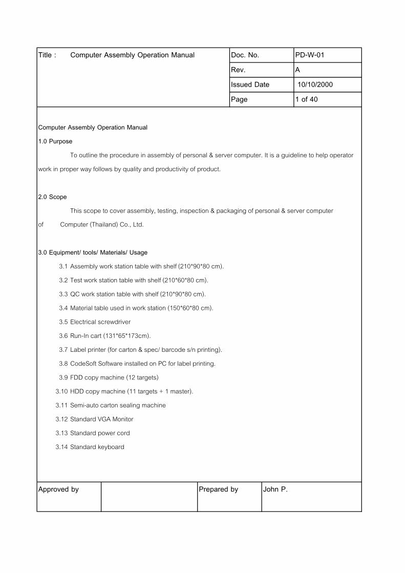
Title : Computer Assembly Operation Manual Doc. No. PD-W-01
Rev. A
Issued Date 10/10/2000
Page 1 of 40
Computer Assembly Operation Manual
1.0 Purpose
To outline the procedure in assembly of personal & server computer. It is a guideline to help operator
work in proper way follows by quality and productivity of product.
2.0 Scope
This scope to cover assembly, testing, inspection & packaging of personal & server computer
of Acer Computer (Thailand) Co., Ltd.
3.0 Equipment/ tools/ Materials/ Usage
3.1 Assembly work station table with shelf (210*90*80 cm).
3.2 Test work station table with shelf (210*60*80 cm).
3.3 QC work station table with shelf (210*90*80 cm).
3.4 Material table used in work station (150*60*80 cm).
3.5 Electrical screwdriver
3.6 Run-In cart (131*65*173cm).
3.7 Label printer (for carton & spec/ barcode s/n printing).
3.8 CodeSoft Software installed on PC for label printing.
3.9 FDD copy machine (12 targets)
3.10 HDD copy machine (11 targets + 1 master).
3.11 Semi-auto carton sealing machine
3.12 Standard VGA Monitor
3.13 Standard power cord
3.14 Standard keyboard
Approved by Prepared by John P.
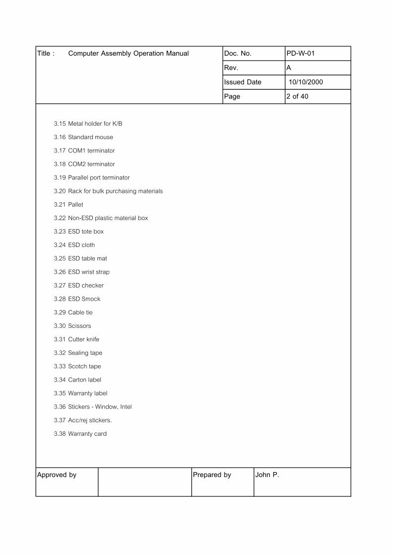
Title : Computer Assembly Operation Manual Doc. No. PD-W-01
Rev. A
Issued Date 10/10/2000
Page 2 of 40
3.15 Metal holder for K/B
3.16 Standard mouse
3.17 COM1 terminator
3.18 COM2 terminator
3.19 Parallel port terminator
3.20 Rack for bulk purchasing materials
3.21 Pallet
3.22 Non-ESD plastic material box
3.23 ESD tote box
3.24 ESD cloth
3.25 ESD table mat
3.26 ESD wrist strap
3.27 ESD checker
3.28 ESD Smock
3.29 Cable tie
3.30 Scissors
3.31 Cutter knife
3.32 Sealing tape
3.33 Scotch tape
3.34 Carton label
3.35 Warranty label
3.36 Stickers - Window, Intel
3.37 Acc/rej stickers.
3.38 Warranty card
Approved by Prepared by John P.
Title : Computer Assembly Operation Manual Doc. No. PD-W-01
Rev. A
Issued Date 10/10/2000
Page 3 of 40
3.39 Assembly record forms
3.40 Cleaning cloths
3.41 Cleaning Detergent
3.42 3.5" Diskette
3.43 Speakers
3.44 Multimeter
3.45 Screwdriver
3.46 Pliers
3.47 screws
3.48 Marker pen
Approved by Prepared by John P.
Title : Computer Assembly Operation Manual Doc. No. PD-W-01
Rev. A
Issued Date 10/10/2000
Page 4 of 40
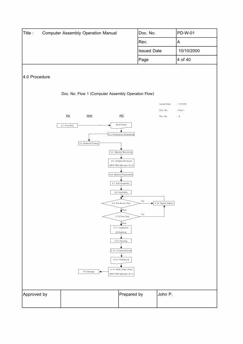
4.0 Procedure
Doc. No. Flow 1 (Computer Assembly Operation Flow)
Approved by Prepared by John P.
Issued Date : 10/10/00
Doc. No. : Flow 1
PA W/H PD Rev. No. : A
Fail
Pass
Fail
Pass
4.1 Pr int W/O
4.3 Material Picking
4.5 Component Issue
MFG-PRO Maintain 16.10
4.6 Mater ial Preparation
4.8 Assembly
4.9 Pre Run-In Test
4.10 Final Test
4.11 Inspection
& Cleaning
4.12 Packing
4.13 Finished Goods
4.16 Repair Station
4.7 Sub-Assembly
F/G Storage
4.2 Production Schedul ing
Work Order
4.4 Mater ial Receiving
4.15 Work Order Close
MFG-PRO Maintain 16.11
4.14 F/G Record

Title : Computer Assembly Operation Manual Doc. No. PD-W-01
Rev. A
Issued Date 10/10/2000
Page 5 of 40
4.1 Print W/O
4.1.1 PA prints work order out at production printer names PRODPRN1 (a work order has 3 copies).
4.1.2 Assistant Production Manager to review work order and ensure the w/o correct.
Sample of work order print out
woworl.p v01.01 16.6 Work Order Release/ Print Date : 12/6/2000
Page : 1 Acer Computer Co., Ltd. Time : 8:42:32
WORK ORDER PICKLIST
Work Order : 30001698 Issue Date : 12/4/2000
ID : 40037804 Release Date : 12/4/2000
Item Number : AT.39J01.020XT Rev : Work Order Due Date: 12/7/2000
Power Sx C700, 64M, 20G, 52X, 56K (Askey), W98 P-L :
Remarks : Sales/Job : BTS
Qty Order : 30.0 Deliver To :
Item Number Site Bin No. Req-Qty UM Loc Issued Receiver
_ _ _ _ _ _ _ _ _ _ _ _ _ _ _ _ _ _ _ _ _ _ _ _ _ _ _ _ _ _ _ _ _ _ _ _ _ _ _ _ _ _ _ _ _ _ _ _ _ _ _ _ _ _ _ _ _ _ _ _
01.ICLON.70C 1000 30 PC 1220 ( 0 )
CPU C700 (128KB) FC-PGA
40.00060.081 1000 30 PC 1220 ( 0 )
LABEL Celeron Intel (Housing)
Approved by Prepared by John P.
Title : Computer Assembly Operation Manual Doc. No. PD-W-01
Rev. A
Issued Date 10/10/2000
Page 6 of 40
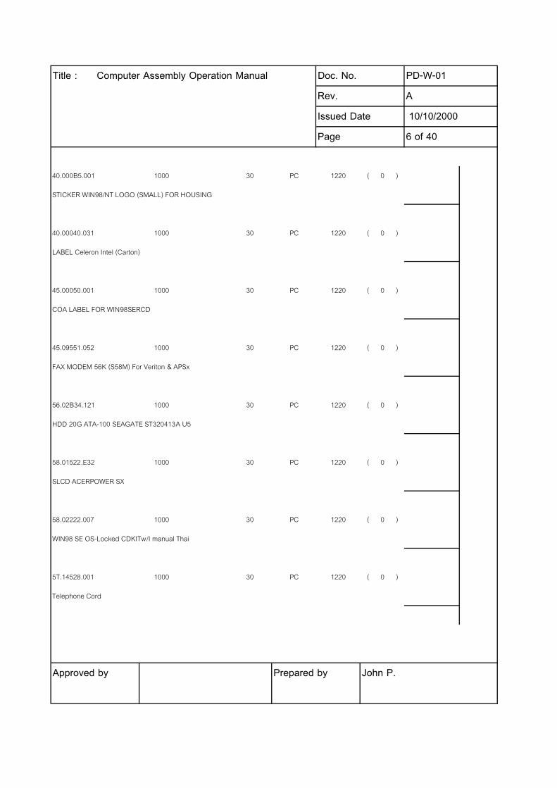
40.000B5.001 1000 30 PC 1220 ( 0 )
STICKER WIN98/NT LOGO (SMALL) FOR HOUSING
40.00040.031 1000 30 PC 1220 ( 0 )
LABEL Celeron Intel (Carton)
45.00050.001 1000 30 PC 1220 ( 0 )
COA LABEL FOR WIN98SERCD
45.09551.052 1000 30 PC 1220 ( 0 )
FAX MODEM 56K (S58M) For Veriton & APSx
56.02B34.121 1000 30 PC 1220 ( 0 )
HDD 20G ATA-100 SEAGATE ST320413A U5
58.01522.E32 1000 30 PC 1220 ( 0 )
SLCD ACERPOWER SX
58.02222.007 1000 30 PC 1220 ( 0 )
WIN98 SE OS-Locked CDKITw/I manual Thai
5T.14528.001 1000 30 PC 1220 ( 0 )
Telephone Cord
Approved by Prepared by John P.

Title : Computer Assembly Operation Manual Doc. No. PD-W-01
Rev. A
Issued Date 10/10/2000
Page 7 of 40
5T.14528.001 1000 30 PC 1220 ( 0 )
Telephone Cord
5T.14529.001 1000 60 PC 1220 ( 0 )
CORD FOR DESKTOP 110V
5T.49067.001 1000 30 PC 1220 ( 0 )
WARRANTY CARD ACERPUT IN ALL BOX
5T.85227.001 1000 30 PC 1220 ( 0 )
CABLE 40 PIN FOR HDD
71.63350.114 1000 30 PC 1220 ( 0 )
MEM 64MB PC 133 INFINEONAPACER
90.00028.632 1000 30 PC 1220 ( 0 )
HSINK SOCKET370/SOCKET7w/oTDM 3PIN FOR APSx, VT
90.35G26.001 1000 30 PC 1220 ( 0 )
MOUSE Logitech 2 botton/wheel 48A Ind.pack
91.39D37.207 1000 30 PC 1220 ( 0 )
CD-ROM 52 AOPEN, Acer color Ind.pack CD-952E/TKU
Approved by Prepared by John P.
Title : Computer Assembly Operation Manual Doc. No. PD-W-01
Rev. A
Issued Date 10/10/2000
Page 8 of 40
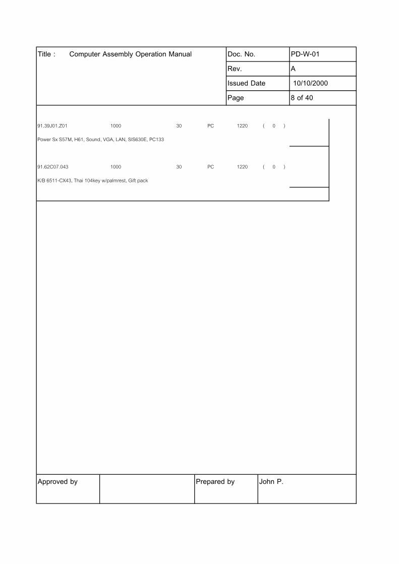
91.39J01.Z01 1000 30 PC 1220 ( 0 )
Power Sx S57M, H61, Sound, VGA, LAN, SIS630E, PC133
91.62C07.043 1000 30 PC 1220 ( 0 )
K/B 6511-CX43, Thai 104key w/palmrest, Gift pack
Approved by Prepared by John P.

Title : Computer Assembly Operation Manual Doc. No. PD-W-01
Rev. A
Issued Date 10/10/2000
Page 9 of 40
4.2 Production Schedule
4.2.1 Assistant Production Manager to review work order for priority and then schedule for production.
4.2.2 Assistant Production Manager gives work order to sub-assy staff to record work order number, quantity,
model, date, time on white board (see attached Doc. No. PD-F-01). Then give work order to warehouse staffs for
picking materials.
Doc. No. PD-F-01 (Work Order Tracking and Status Update)
Approved by Prepared by John P.
Issue date : 10/10/00
Doc. No. : PD-F-01
Rev. : A
Doc. No. PD-F-01 Work Order Tracking and Status Update
Item Date Time W/O Customer Model Qty Mat'l Pick Sub-Assy Assy Pre- Run-In Final Test QC Ins Pack F/G Remark
1
2
3
4
5
6
7
8
9
10
11
12
13
14
15
16
17
18
19
20
Title : Computer Assembly Operation Manual Doc. No. PD-W-01
Rev. A
Issued Date 10/10/2000
Page 10 of 40
4.3 Material Picking
4.3.1 Warehouse staffs to pick materials as work order states and deliver materials to production line
and put at material preparation area.
4.4 Material Receiving
4.4.1 Sub-assy staff to check materials as work order states, count quantity, inspect component item
number. Make sure to have no materials damage before signing work order material receipt.
4.4.2 Sub-assy staff keeps the 2nd copy of work order for production & QC staffs reference, gives the
1st copy of work order to warehouse staff for reference and return the original work order to Assistant
Production Manager for component issue (MFG-Pro Maintain 16.10).
4.5 Component Issue (MFG-Pro Maintain 16.10)
4.5.1 Assistant Production Manager to perform MFG-PRO.
4.5.2 Put the user ID & Password then enter.
4.5.3 MFG-Pro system shows the main Mann as below.
Approved by Prepared by John P.

Title : Computer Assembly Operation Manual Doc. No. PD-W-01
Rev. A
Issued Date 10/10/2000
Page 11 of 40
Main Menu 12/04/00
DISTRIBUTION MANUFACTURING FINANCIAL
1. Items/Sites 13. Product Structures 25. General Ledger
2. Addresses/Taxes 14 26. Multiple Currency
3. Inventory Control 15 27. Accounts Receivable
4. Physical Inventory 16. Work Orders 28. Accounts Payable
5. Purchasing 17 29
6 18 30
7. Sales Orders/Invoice 19 31
8. Configured Products 20 32
9. Sales Analysis 21. New Sales Forecast 33
10 22 34
11 23 35
12 24. Key Component 36. Manager Functions
4.5.4 Put 16.10 (MFG-Pro Maintain for work order component issue) then enter.
wowois.p h 16.10 Work Order Component Issue 12/04/00
Work Order: ID: T#: Effdate: 12/04/00
Item Number: Status: Issue Alloc: no
Issue Picked: yes
Approved by Prepared by John P.
Title : Computer Assembly Operation Manual Doc. No. PD-W-01
Rev. A
Issued Date 10/10/2000
Page 12 of 40
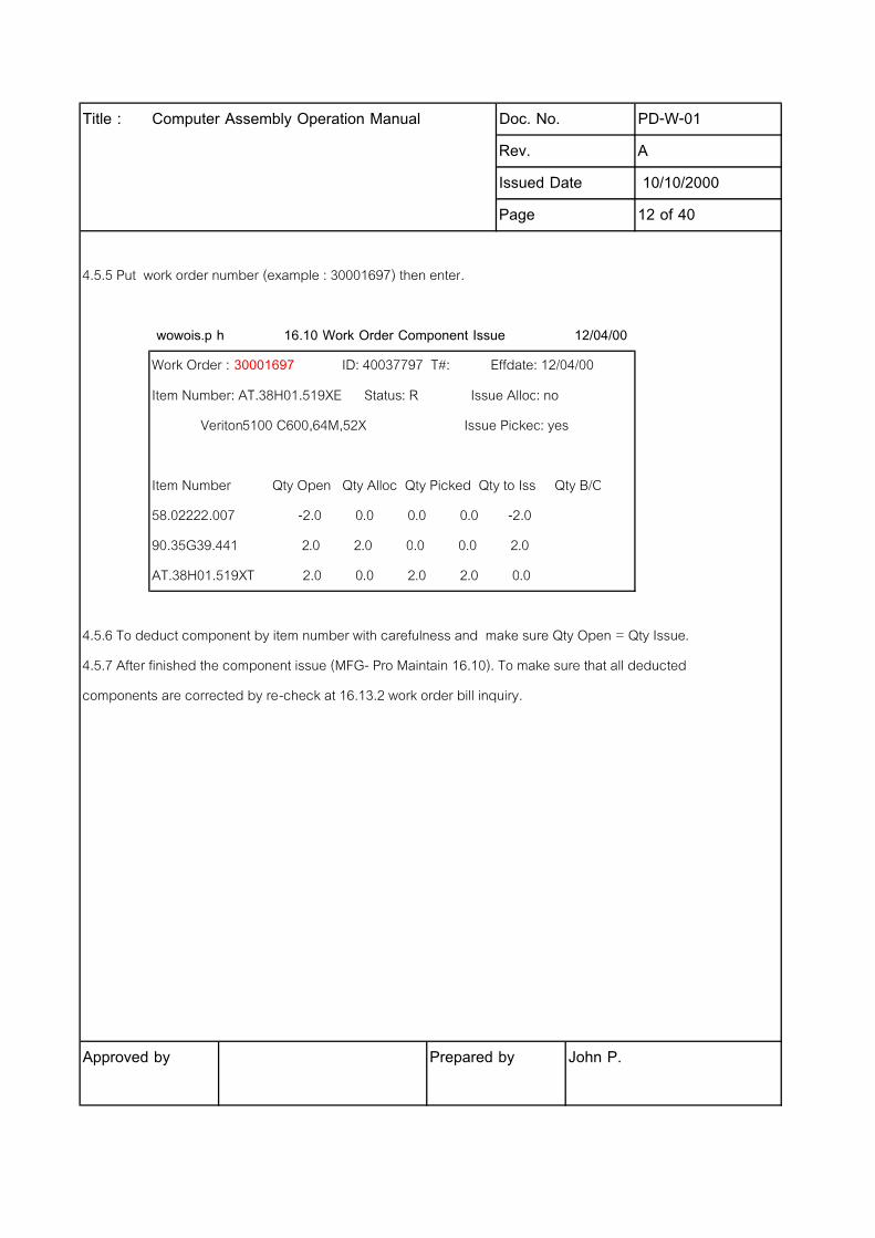
4.5.5 Put work order number (example : 30001697) then enter.
wowois.p h 16.10 Work Order Component Issue 12/04/00
Work Order : 30001697 ID: 40037797 T#: Effdate: 12/04/00
Item Number: AT.38H01.519XE Status: R Issue Alloc: no
Veriton5100 C600,64M,52X Issue Picked: yes
Item Number Qty Open Qty Alloc Qty Picked Qty to Iss Qty B/O
58.02222.007 -2.0 0.0 0.0 0.0 -2.0
90.35G39.441 2.0 2.0 0.0 0.0 2.0
AT.38H01.519XT 2.0 0.0 2.0 2.0 0.0
4.5.6 To deduct component by item number with carefulness and make sure Qty Open = Qty Issue.
4.5.7 After finished the component issue (MFG- Pro Maintain 16.10). To make sure that all deducted
components are corrected by re-check at 16.13.2 work order bill inquiry.
Approved by Prepared by John P.

Title : Computer Assembly Operation Manual Doc. No. PD-W-01
Rev. A
Issued Date 10/10/2000
Page 13 of 40
4.5.8 Put work order number (example : 30001678) then enter.
wowaiq.p V2.00I 16.13.2 Work Order Bill Inquiry 12/04/00
Work Order ID Component Item Output
30001678 terminal
Work Order ID Component Item Loc Qty Req Qty Allo Qty Pick Qty Iss
-------------- ---------- --------------------- ----- ------ ------- ------- -----
30001678 40037512 01.COPRM.86B 1220 20 0 0 20
30001678 40037512 40.00060.111 1220 20 0 0 20
30001678 40037512 45.00040.061 1220 20 0 0 20
30001678 40037512 45.00050.121 1220 20 0 0 20
30001678 40037512 53.30K04.001 1220 20 0 0 20
30001678 40037512 54.09551.052 1220 20 0 0 20
30001678 40037512 56.02B34.121 1220 20 0 0 20
30001678 40037512 58.02254.005 1220 20 0 0 20
30001678 40037512 5T.14528.001 1220 20 0 0 20
30001678 40037512 5T.14529.001 1220 40 0 0 40
30001678 40037512 5T.49067.001 1220 20 0 0 20
30001678 40037512 71.63350.364 1220 20 0 0 20
4.5.9 To check and make sure Qty Required = Qty Issued before exit from MFG-Pro.
Approved by Prepared by John P.
Title : Computer Assembly Operation Manual Doc. No. PD-W-01
Rev. A
Issued Date 10/10/2000
Page 14 of 40
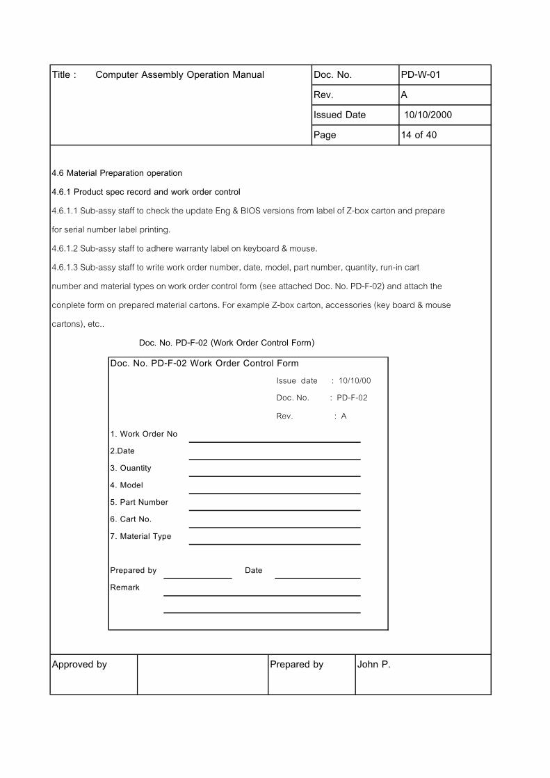
4.6 Material Preparation operation
4.6.1 Product spec record and work order control
4.6.1.1 Sub-assy staff to check the update Eng & BIOS versions from label of Z-box carton and prepare
for serial number label printing.
4.6.1.2 Sub-assy staff to adhere warranty label on keyboard & mouse.
4.6.1.3 Sub-assy staff to write work order number, date, model, part number, quantity, run-in cart
number and material types on work order control form (see attached Doc. No. PD-F-02) and attach the
conplete form on prepared material cartons. For example Z-box carton, accessories (key board & mouse
cartons), etc..
Doc. No. PD-F-02 (Work Order Control Form)
Approved by Prepared by John P.
Doc. No. PD-F-02 Work Order Control Form
Issue date : 10/10/00
Doc. No. : PD-F-02
Rev. : A
1. Work Order No
2.Date
3. Ouantity
4. Model
5. Part Number
6. Cart No.
7. Material Type
Prepared by Date
Remark
Title : Computer Assembly Operation Manual Doc. No. PD-W-01
Rev. A
Issued Date 10/10/2000
Page 15 of 40
4.6.2 Z-Box
4.6.2.1 Unpack carton and take Z-Box to put on run-in cart . Care should be taken not to put Z-Box
too close to each other to avoid scratching.
4.6.2.2 Replace the plastic bag and system end cap into the system box.
4.6.2.3 Remove all the accessories from the system box and prepare them ready for packing.
4.7 Sub assembly
4.7.1 Label Preparation
4.7.1.1 Turn on the printer and align printer label.
4.7.1.2 Open a file related to the product name & p/n as w/o states.
4.7.1.3 Check the file of the said part number against the work order.
4.7.1.4 Record details (Product name, Product number, Spec., Eng version, BIOS version
Serial number, Work order number, date in S/N label printing control form (see attached Doc. No. PD-F-03).
4.7.1.5 Fill up the necessary information (Product name, Product number, Spec., Eng version, BIOS
version, Serial no., w/o no., Warranty , Mfg. date) and assign an unused sequential serial number.
Then process printing product serial number label. After finished printing, to check and
ensure there is no errors, duplicate and complete details then save the latest file.
Approved by Prepared by John P.

Title : Computer Assembly Operation Manual Doc. No. PD-W-01
Rev. A
Issued Date 10/10/2000
Page 16 of 40
Doc. No. PD-F-03 (Serial Number Label Printing Control Form)
4.7.2 Warranty label sticking
4.7.2.1 Pick all components as required per work order. Re-check correctness of components.
4.7.2.2 Mark by ticking on the warranty label the year and month when the said component is
being used for assembly.
4.7.2.3 Adhere warranty label to prepared CD-ROM, HDD, CPU with converter (slot form factor), Memory,
Add on Card and make sure warranty labels do not cause short circuit of components.
4.7.2.4 Prepare warranty label for assembly operation to adhere on components inside Z-box such as
PS, M/B, FDD, CPU without converter (socket form factor).
Approved by Prepared by John P.
Issued date : 10/10/00
Doc. No. : PD-F-03
Rev. : A
Doc. No. PD-F-03 Serial Number Label Printing Control Form
Item Date W/O Product Product Number Specification Eng. BIOS S/N Number Qty Checked by/
Name Version Version Date
1
2
3
4
5
6
7
8
9
10
11
12
13
14
15
16
17
18
19
20
Title : Computer Assembly Operation Manual Doc. No. PD-W-01
Rev. A
Issued Date 10/10/2000
Page 17 of 40
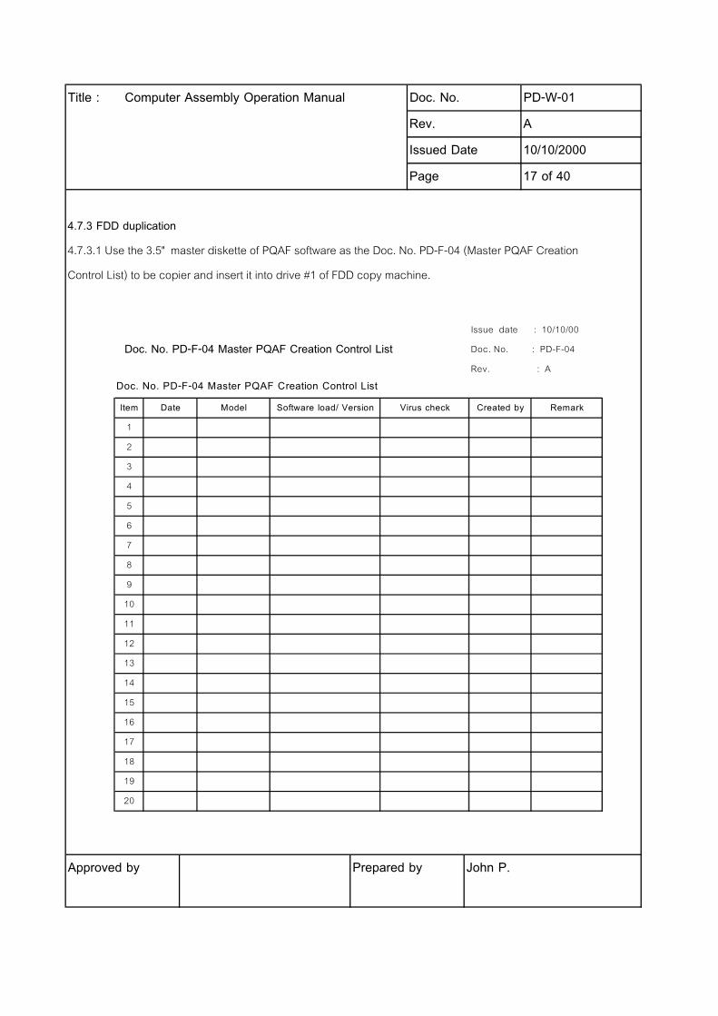
4.7.3 FDD duplication
4.7.3.1 Use the 3.5" master diskette of PQAF software as the Doc. No. PD-F-04 (Master PQAF Creation
Control List) to be copier and insert it into drive #1 of FDD copy machine.
Doc. No. PD-F-04 Master PQAF Creation Control List
Approved by Prepared by John P.
Issue date : 10/10/00
Doc. No. : PD-F-04
Rev. : A
Doc. No. PD-F-04 Master PQAF Creation Control List
Item Date Model Software load/ Version Virus check Created by Remark
1
2
3
4
5
6
7
8
9
10
11
12
13
14
15
16
17
18
19
20
Title : Computer Assembly Operation Manual Doc. No. PD-W-01
Rev. A
Issued Date 10/10/2000
Page 18 of 40
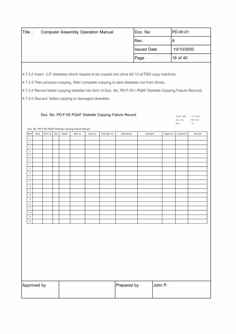
4.7.3.2 Insert 3.5" diskettes which require to be copied into drive #2-12 of FDD copy machine.
4.7.3.3 Then process copying. After complete copying to take diskettes out from drives.
4.7.3.4 Record failed copying diskette into form of Doc. No. PD-F-05 ( PQAF Diskette Copying Failure Record).
4.7.3.5 Discard failed copying or damaged diskettes.
Doc. No. PD-F-05 PQAF Diskette Copying Failure Record
Approved by Prepared by John P.
Issue date : 10/10/00
Doc. No. : PD-F-05
Rev. : A
Doc. No. PD-F-05 PQAF Diskette Copying Failure Record
Item Date W/O no. Qty Model Item no. Disk s/n Disk Item no. Description symptom Target No. Copied by Remark
1
2
3
4
5
6
7
8
9
10
11
12
13
14
15
16
17
18
19
20
Title : Computer Assembly Operation Manual Doc. No. PD-W-01
Rev. A
Issued Date 10/10/2000
Page 19 of 40
4.7.4 HDD duplication
4.7.4.1 Master HDD Creation
4.7.4.1.1 Assemble a master set of computer as work order specifications state.
4.7.4.1.2 Connect power cord, mouse, keyboard and monitor to computer.
4.7.4.1.3 Use the original master HDD connects to IDE2 of M/B.
4.7.4.1.4 Insert 3.5" diskette with Ghost software into A drive.
4.7.4.1.5 Turn on power and check BIOS version versus work order states. If BIOS does not match,
to do afflash by using aflash software with 3.5" diskette insert into drive A. After finished
Aflash then to setup BIOS again and update date, month, year after that save it.
4.7.4.1.6 Machine is automatically started and go to DOS (drive A) then run program Ghost.
4.7.4.1.7 Go to Local ---> Disk ---> From Image ---> File Name Local Image From
4.7.4.1.7.1 A : Local Drive
4.7.4.1.7.2 C : Local Drive
4.7.4.1.7.3 D : Local Drive
4.7.4.1.8 Select Local Drive C or D if has drive D.
4.7.4.1.9 Select file from current master HDD list to conform as work order item number states,
to select 1 then click OK.
Approved by Prepared by John P.
Title : Computer Assembly Operation Manual Doc. No. PD-W-01
Rev. A
Issued Date 10/10/2000
Page 20 of 40
4.7.4.1.10 Select required drive to be copied then click OK.
4.7.4.1.11 Process with disk load, select yes answer then enter.
4.7.4.1.12 When finished HDD creation to turn off power then take off original master HDD
and Ghost 3.5" disk.
4.7.4.1.13 If work order states to have CD-ROM, Connect IDE2 to CD-ROM.
4.7.4.1.14 Turn on power and go to Windows to detect new hardware.
4.7.4.1.15 If the new hardware is detected, to load driver for new hardware which can search from
C:\ Acer\ Driver or D:\ driver of SLCD. Notify to TSD & PM if the driver is not available.
4.7.4.1.16 When finished driver installation to check at \Ghost Panal\ System\ Device Manager
to make sure that new hardware is completely installed the driver.
4.7.4.1.17 If new hardware is not completely installed the driver. It will present question mark (?).
4.7.4.1.18 To install driver with hardware with question mark (?). Go to remove then refresh.
4.7.4.1.19 Windows to detect new hardware again. To complete driver installation by
repeating item 4.7.4.1.15 again.
4.7.4.1.20 When complete driver installation to use start menu to shutdown computer.
Avoid to shutdown at OEM Reset Reminder by answer NO.
4.7.4.1.21 All master HDD after creation must adhere with the name of master and the date of creation,
see the attached Doc. No. PD-F-06 (Master HDD Creation Tracking Form).
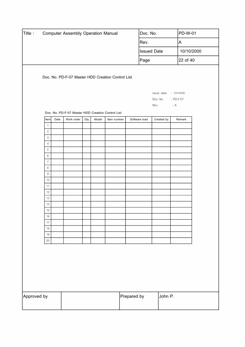
4.7.4.1.22 All master HDD created must be written on the control lists with all the software that were loaded.
see the attached Doc. No. PD-F-07 (Master HDD Creation Control List).
4.7.4.1.23 Give the new created master HDD to sub-assy staff for HDD copying.
Approved by Prepared by John P.

Title : Computer Assembly Operation Manual Doc. No. PD-W-01
Rev. A
Issued Date 10/10/2000
Page 21 of 40
Doc. No. PD-F-06 Master HDD Creation Tracking Form
Approved by Prepared by John P.
Doc. No. PD-F-06 Issue date : 10/10/00
Master HDD Creation Tracking Form Doc. No. : PD-F-06
Rev. : A
Work order :
Quantity
Model :
Item number :
Software load :
Created by :
Date :
Title : Computer Assembly Operation Manual Doc. No. PD-W-01
Rev. A
Issued Date 10/10/2000
Page 22 of 40
Doc. No. PD-F-07 Master HDD Creation Control List
Approved by Prepared by John P.
Issue date : 10/10/00
Doc. No. : PD-F-07
Rev. : A
Doc. No. PD-F-07 Master HDD Creation Control List
Item Date Work order Qty Model Item number Software load Created by Remark
1
2
3
4
5
6
7
8
9
10
11
12
13
14
15
16
17
18
19
20
Title : Computer Assembly Operation Manual Doc. No. PD-W-01
Rev. A
Issued Date 10/10/2000
Page 23 of 40
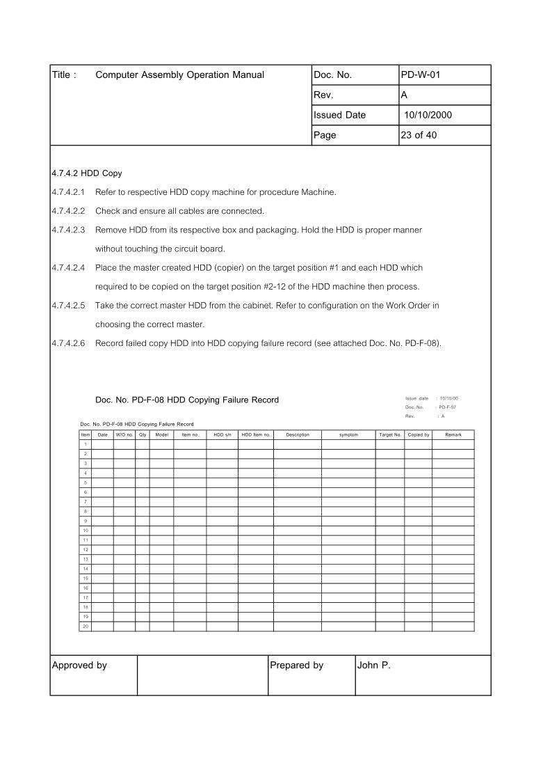
4.7.4.2 HDD Copy
4.7.4.2.1 Refer to respective HDD copy machine for procedure Machine.
4.7.4.2.2 Check and ensure all cables are connected.
4.7.4.2.3 Remove HDD from its respective box and packaging. Hold the HDD is proper manner
without touching the circuit board.
4.7.4.2.4 Place the master created HDD (copier) on the target position #1 and each HDD which
required to be copied on the target position #2-12 of the HDD machine then process.
4.7.4.2.5 Take the correct master HDD from the cabinet. Refer to configuration on the Work Order in
choosing the correct master.
4.7.4.2.6 Record failed copy HDD into HDD copying failure record (see attached Doc. No. PD-F-08).
Doc. No. PD-F-08 HDD Copying Failure Record
Approved by Prepared by John P.
Issue date : 10/10/00
Doc. No. : PD-F-07
Rev. : A
Doc. No. PD-F-08 HDD Copying Failure Record
Item Date W/O no. Qty Model Item no. HDD s/n HDD Item no. Description symptom Target No. Copied by Remark
1
2
3
4
5
6
7
8
9
10
11
12
13
14
15
16
17
18
19
20
Title : Computer Assembly Operation Manual Doc. No. PD-W-01
Rev. A
Issued Date 10/10/2000
Page 24 of 40
4.7.5 Work order control preparation
4.7.5.1 Sub-assy staff to write work order number, date, model, item number, quantity, run-in cart
number and material types on work order control form (see attached Doc. No. PD-F-02) and attach on the
prepared components such as HDD, CPU, memory, add on cards, CD-ROM etc.
4.8 Assembly operation
4.8.1 Prepare materials which provided by material preparation and sub-assy.
4.8.2 Unscrew and open the casing.
4.8.3 Adhere Product Spec label and Serial Number label at rear of machine.
4.8.4 Install the CD-ROM drive and tighten the screws, ensure the cables are properly connected. Tie
the cables nicely with cable tie and cut the excess of cable tie using scissors.
Approved by Prepared by John P.
Title : Computer Assembly Operation Manual Doc. No. PD-W-01
Rev. A
Issued Date 10/10/2000
Page 25 of 40
4.8.5 Remove FDD cable and take off FDD drive, adhere warranty label & s/n on FDD drive. Also
adhere s/n label on HDD, CD-ROM, PS, M/B and warranty label on PS, M/B, then re-install FDD drive back to
frame, install HDD to frame and tighten the screws both sides. To ensure relevant HDD cables are
properly connected. Tie the cables nicely to wire cable tie. Cut the excess of cable tie using scissors.
4.8.6 Install the CPU and attach heatsink on CPU then adhere warranty label on CPU heatsink. Ensure
all wires are properly connected and not touching the fans of the heatsink.
4.8.7 Install the memory. Ensure memory are properly installed. Installer should be able to hear the
"clicking" sound if memory is proper sit into its slot.
4.8.8 Unscrew and remove the bracket of each relevant slot for add on card.
4.8.9 Install the add on cards and tighten the screw.
4.8.10 Install other components such as Lan Card etc as required. Ensure all screws are properly
secured, all cables and wires are properly connected and nicely tied by cable tie and nicely trimmed.
4.8.11Close the casing and tighten the respective screws.
4.8.12 Put the rest labels on top of case and stick by clear plastic tape.
4.8.13 Insert the prepared PQAF diskette into FDD drive then perform pre run-in test.
Approved by Prepared by John P.
Title : Computer Assembly Operation Manual Doc. No. PD-W-01
Rev. A
Issued Date 10/10/2000
Page 26 of 40
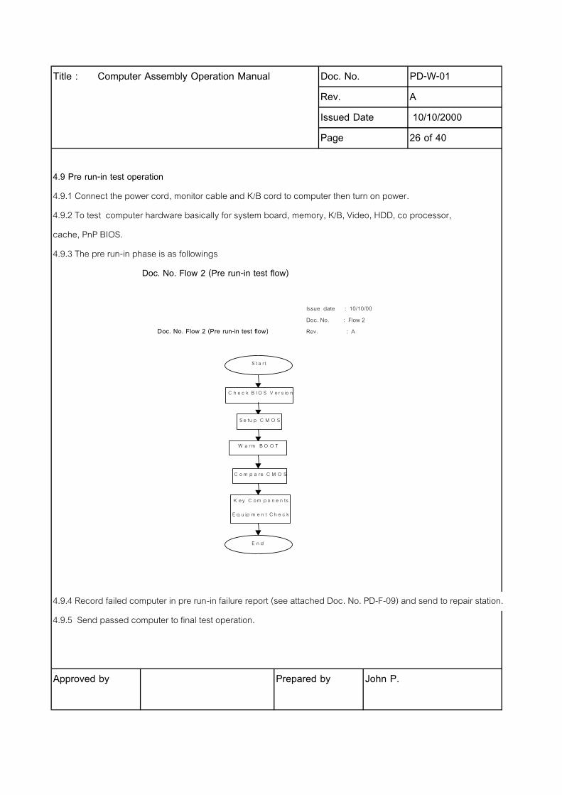
4.9 Pre run-in test operation
4.9.1 Connect the power cord, monitor cable and K/B cord to computer then turn on power.
4.9.2 To test computer hardware basically for system board, memory, K/B, Video, HDD, co processor,
cache, PnP BIOS.
4.9.3 The pre run-in phase is as followings
Doc. No. Flow 2 (Pre run-in test flow)
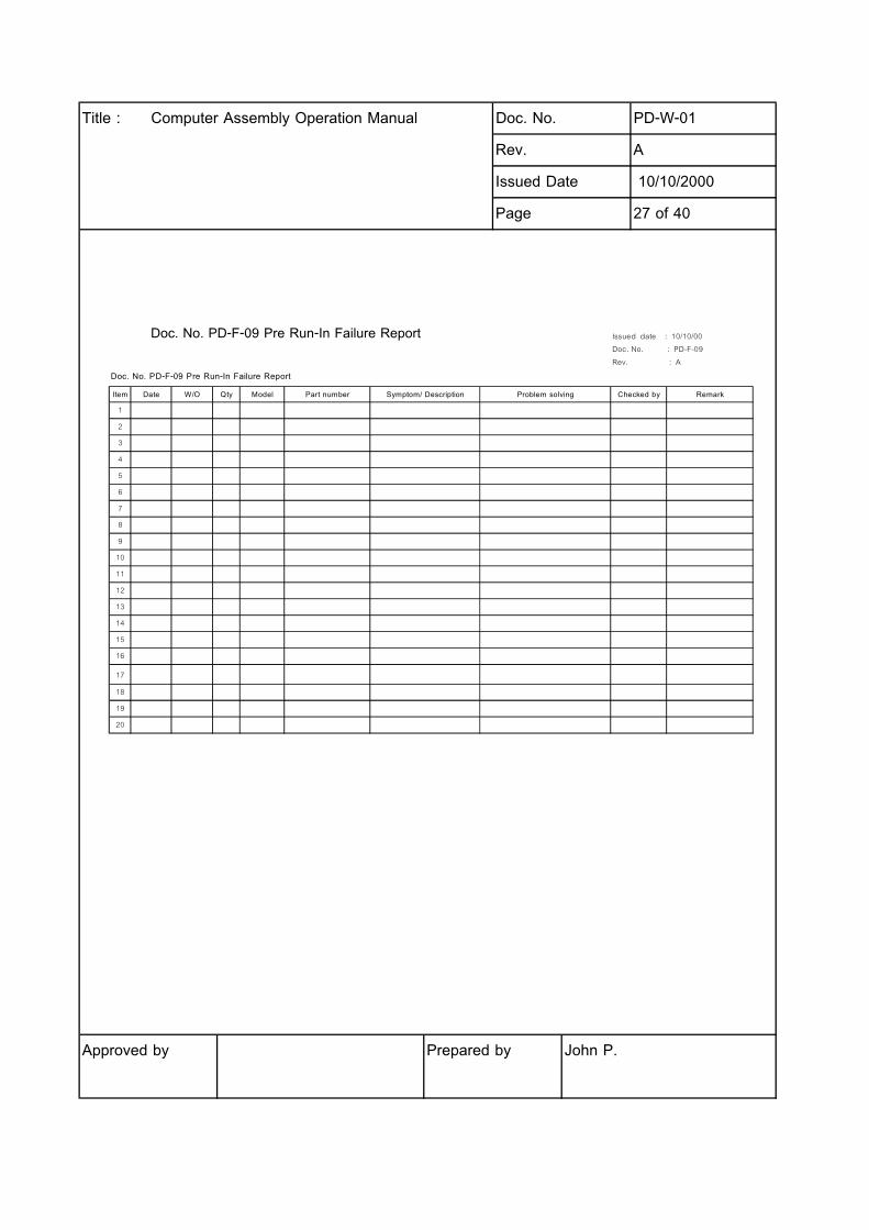
4.9.4 Record failed computer in pre run-in failure report (see attached Doc. No. PD-F-09) and send to repair station.
4.9.5 Send passed computer to final test operation.
Approved by Prepared by John P.
Issue date : 10/10/00
Doc. No. : Flow 2
Doc. No. Flow 2 (Pre run-in test flow) Rev. : A
S t a r t
C h e c k B I O S V e r s io n
S e tu p C M O S
W a rm B O O T
C o m p a re C M O S
K e y C o m p o n e n ts
E q u ip m e n t C h e c k
E n d
Title : Computer Assembly Operation Manual Doc. No. PD-W-01
Rev. A
Issued Date 10/10/2000
Page 27 of 40
Doc. No. PD-F-09 Pre Run-In Failure Report
Approved by Prepared by John P.
Issued date : 10/10/00
Doc. No. : PD-F-09
Rev. : A
Doc. No. PD-F-09 Pre Run-In Failure Report
Item Date W/O Qty Model Part number Symptom/ Description Problem solving Checked by Remark
1
2
3
4
5
6
7
8
9
10
11
12
13
14
15
16
17
18
19
20

Title : Computer Assembly Operation Manual Doc. No. PD-W-01
Rev. A
Issued Date 10/10/2000
Page 28 of 40
4.10 Final test operation
4.10.1 Move computer from run-in cart and place it on workstation.
4.10.2 Use K/B & mouse to conform its model.
4.10.3 Connect the power cord, monitor cable, K/B & mouse cords to computer then turn on power.
4.10.4 Check/ update BIOS to conform as spec states.
4.10.5 Connect loop back to test serial port & parallel port.
4.10.6 Computer system check by PQAF (Product Quality Assurance Program for Factory) to ease
troubleshooting of PC system.
4.10.7 Proceed to do the DMI registration with system serial number.
4.10.8 Turn off computer power and remove PQAF diskette.
4.10.9 Turn on computer and check windows operating, CD-ROM sound, check noise and
abnormalities.
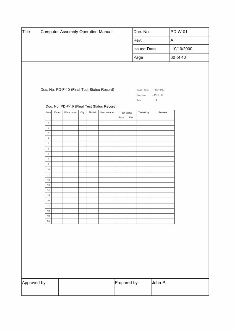
4.10.10 Record final test result in final test test status record (see attached Doc. No. PD-F-10).
4.10.11 If computer failed test, record failure mode/ symptom & description in the final test failure report
(see attached Doc. No. PD-F-11) and adhere test failed sticker at the top of computer then
send to repair station.
4.10.12 Computer passed test is identified by test passed sticker at the rear of computer.
4.10.13 Turn off computer power, remove power cord, monitor cable, K/B & mouse cords.
4.10.14 Put on run-in cart and move to cleaning & inspection operation.
Approved by Prepared by John P.
Title : Computer Assembly Operation Manual Doc. No. PD-W-01
Rev. A
Issued Date 10/10/2000
Page 29 of 40
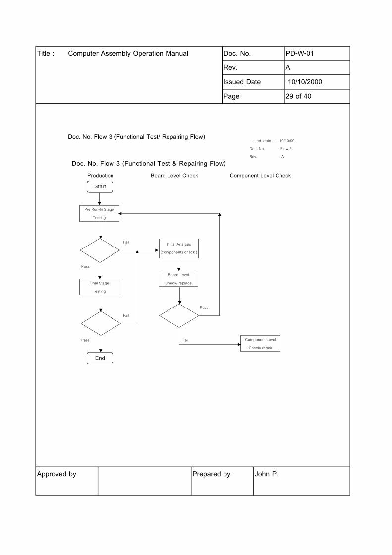
Doc. No. Flow 3 (Functional Test/ Repairing Flow)
Approved by Prepared by John P.
Issued date : 10/10/00
Doc. No. : Flow 3
Rev. : A
Doc. No. Flow 3 (Functional Test & Repairing Flow)
Production Board Level Check Component Level Check
Fail
Pass
Pass
Fail
Pass Fail
Pre Run-In Stage
Testing
Initial Analysis
(components check )
Start
Board Level
Check/ replaceFinal Stage
Testing
End
Component Level
Check/ repair
Title : Computer Assembly Operation Manual Doc. No. PD-W-01
Rev. A
Issued Date 10/10/2000
Page 30 of 40
Doc. No. PD-F-10 (Final Test Status Record)
Approved by Prepared by John P.
Issue date : 10/10/00
Doc. No. : PD-F-10
Rev. : A
Doc. No. PD-F-10 (Final Test Status Record)
Item Date Work order Qty Model Item number Tested by Remark
Pass Fail
1
2
3
4
5
6
7
8
9
10
11
12
13
14
15
16
17
18
19
20
Test status
Title : Computer Assembly Operation Manual Doc. No. PD-W-01
Rev. A
Issued Date 10/10/2000
Page 31 of 40
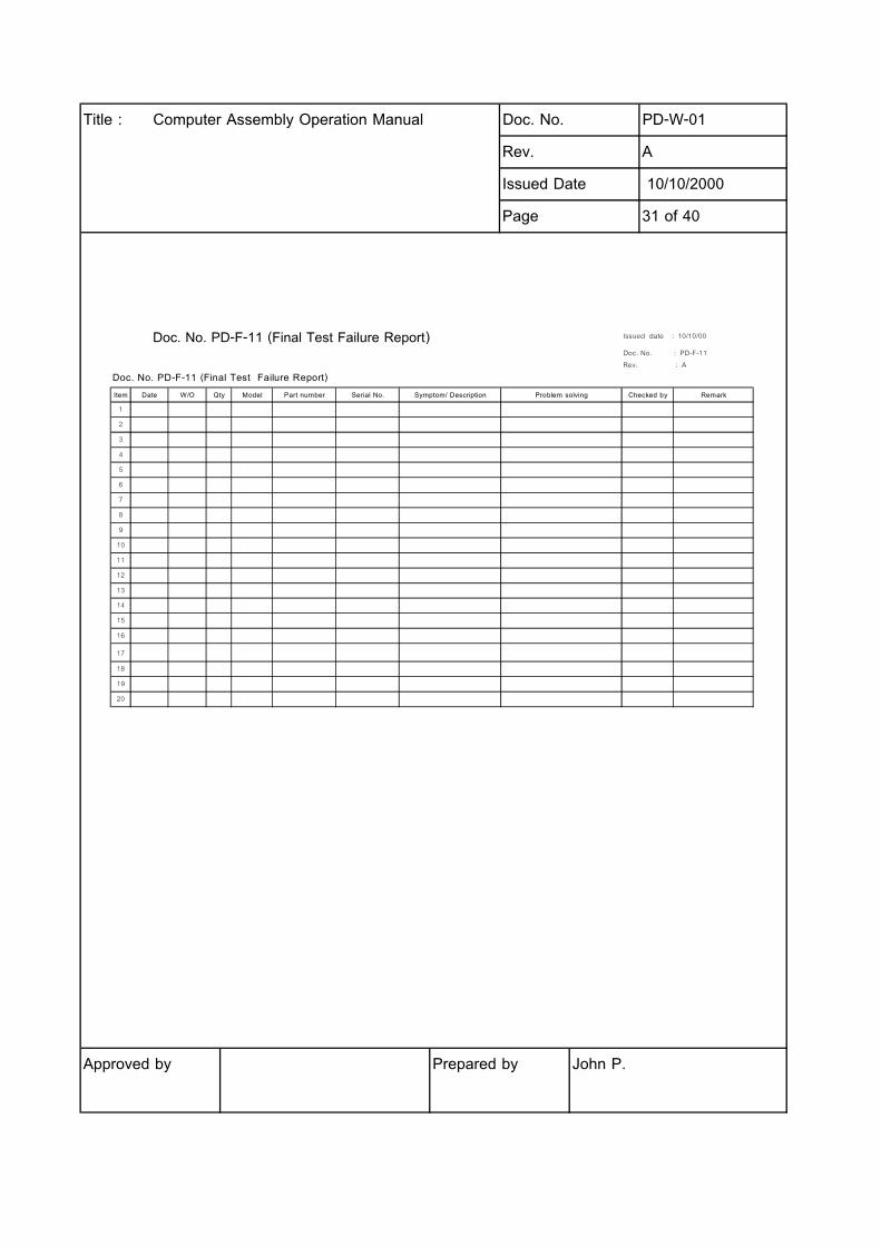
Doc. No. PD-F-11 (Final Test Failure Report)
Approved by Prepared by John P.
Issued date : 10/10/00
Doc. No. : PD-F-11
Rev. : A
Doc. No. PD-F-11 (Final Test Failure Report)
Item Date W/O Qty Model Part number Serial No. Symptom/ Description Problem solving Checked by Remark
1
2
3
4
5
6
7
8
9
10
11
12
13
14
15
16
17
18
19
20
Title : Computer Assembly Operation Manual Doc. No. PD-W-01
Rev. A
Issued Date 10/10/2000
Page 32 of 40
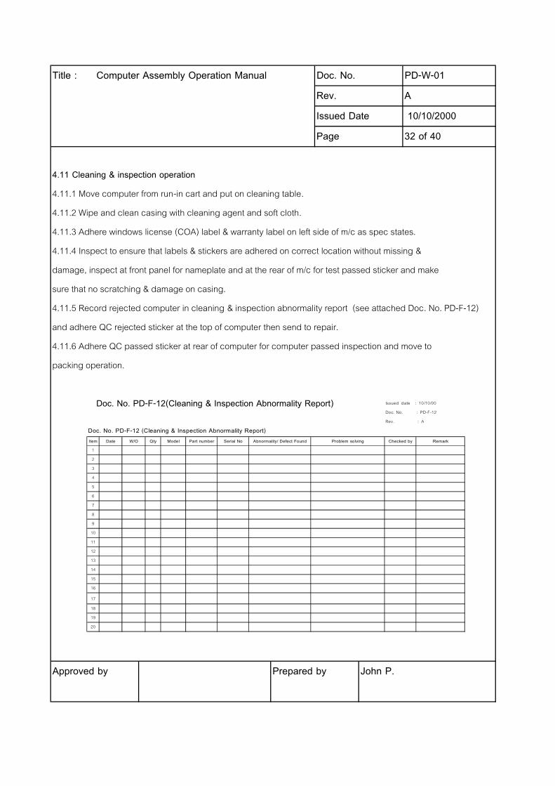
4.11 Cleaning & inspection operation
4.11.1 Move computer from run-in cart and put on cleaning table.
4.11.2 Wipe and clean casing with cleaning agent and soft cloth.
4.11.3 Adhere windows license (COA) label & warranty label on left side of m/c as spec states.
4.11.4 Inspect to ensure that labels & stickers are adhered on correct location without missing &
damage, inspect at front panel for nameplate and at the rear of m/c for test passed sticker and make
sure that no scratching & damage on casing.
4.11.5 Record rejected computer in cleaning & inspection abnormality report (see attached Doc. No. PD-F-12)
and adhere QC rejected sticker at the top of computer then send to repair.
4.11.6 Adhere QC passed sticker at rear of computer for computer passed inspection and move to
packing operation.
Doc. No. PD-F-12(Cleaning & Inspection Abnormality Report)
Approved by Prepared by John P.
Issued date : 10/10/00
Doc. No. : PD-F-12
Rev. : A
Doc. No. PD-F-12 (Cleaning & Inspection Abnormality Report)
Item Date W/O Qty Model Part number Serial No Abnormality/ Defect Found Problem solving Checked by Remark
1
2
3
4
5
6
7
8
9
10
11
12
13
14
15
16
17
18
19
20
Title : Computer Assembly Operation Manual Doc. No. PD-W-01
Rev. A
Issued Date 10/10/2000
Page 33 of 40
4.12 Packing operation
4.12.1 Before packing, to prepare cartons of computer, accessories and re-check for quantity of
accessories.
4.12.2 Put the computer into the plastic bag. Fold the bag nicely and tape it with scotch tape.
4.12.3 Insert the end cap to the computer and put the computer into the system box.
4.12.4 Put accessories such as keyboard, power cord, mouse, warranty card, and a set plastic
bag of " telephone cord, mouse pad , manual, windows manual and SLCD " into the system
box as work order states.
4.12.5 Seal the carton using auto taping machine.
4.12.6 Adhere Product Serial Number label on both sides of carton and also stick the CPU label
such as Pentium III/Celeron label on carton refers to CPU type states in work order.
4.13 Finished goods
4.13.1 When completed packing to take finished goods to put on pallet then deliver finished goods to
put at finished goods area.
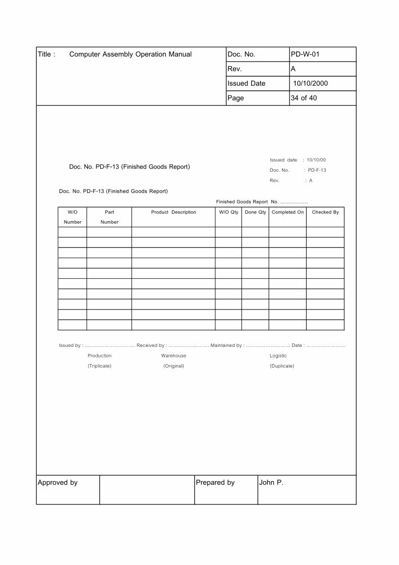
4.14 Finished goods record
4.14.1 When completed w/o, QC staff to record details such as work order number, part number,
product description, work order quantity, done quantity, complete date & checked by into finished
goods report (see attached Doc. No. PD-F-13).
4.14.2 Bring the finished goods report to request for signature from production, warehouse and
logistics for their acknowledgement.
4.14.3 After complete signature on finished goods report then give original copy to warehouse staff,
duplicate copy to logistics staff and triplicate to production staff.
Approved by Prepared by John P.
Title : Computer Assembly Operation Manual Doc. No. PD-W-01
Rev. A
Issued Date 10/10/2000
Page 34 of 40
Doc. No. PD-F-13 (Finished Goods Report)
Approved by Prepared by John P.
Issued date : 10/10/00
Doc. No. : PD-F-13
Rev. : A
Doc. No. PD-F-13 (Finished Goods Report)
Finished Goods Report No. CCCCC..
W/O Part Product Description W/O Qty Done Qty Completed On Checked By
Number Number
Issued by : PPPPPPPPPP. Received by : PPPPPPPP. Maintained by : PPPPPPPPP Date : PPPPPPPP
Production Warehouse Logistic
(Triplicate) (Original) (Duplicate)
Title : Computer Assembly Operation Manual Doc. No. PD-W-01
Rev. A
Issued Date 10/10/2000
Page 35 of 40
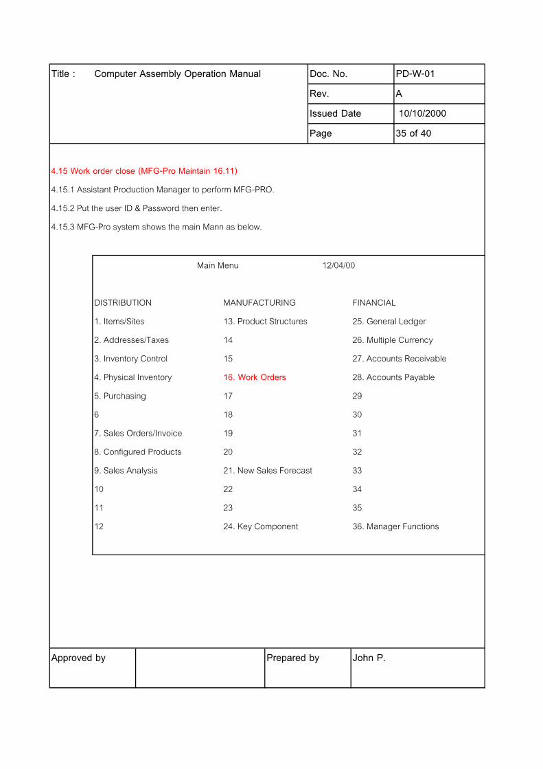
4.15 Work order close (MFG-Pro Maintain 16.11)
4.15.1 Assistant Production Manager to perform MFG-PRO.
4.15.2 Put the user ID & Password then enter.
4.15.3 MFG-Pro system shows the main Mann as below.
Main Menu 12/04/00
DISTRIBUTION MANUFACTURING FINANCIAL
1. Items/Sites 13. Product Structures 25. General Ledger
2. Addresses/Taxes 14 26. Multiple Currency
3. Inventory Control 15 27. Accounts Receivable
4. Physical Inventory 16. Work Orders 28. Accounts Payable
5. Purchasing 17 29
6 18 30
7. Sales Orders/Invoice 19 31
8. Configured Products 20 32
9. Sales Analysis 21. New Sales Forecast 33
10 22 34
11 23 35
12 24. Key Component 36. Manager Functions
Approved by Prepared by John P.

Title : Computer Assembly Operation Manual Doc. No. PD-W-01
Rev. A
Issued Date 10/10/2000
Page 36 of 40
4.15.4 Put 16.11 (MFG-Pro Maintain for work order close) then enter.
woworc.p g 16.11 Work Order Receipt 12/15/00
Work Order: ID: Status:
Remarks:
Item Number: L/S: UM:
Description: Auto Lot Numbers:
Open Qty:
Quantity: Site:
UM: Location:
Conversion: Lot/Serial:
Reject Qty: Ref:
UM: Multi Entry:
Conversion: Total Units:
Ticket#:
Effective:
Close:
Approved by Prepared by John P.
Title : Computer Assembly Operation Manual Doc. No. PD-W-01
Rev. A
Issued Date 10/10/2000
Page 37 of 40
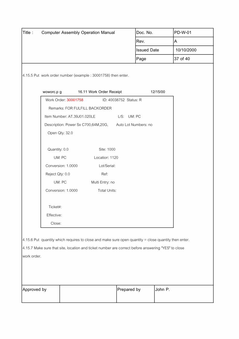
4.15.5 Put work order number (example : 30001758) then enter.
woworc.p g 16.11 Work Order Receipt 12/15/00
Work Order: 30001758 ID: 40038752 Status: R
Remarks: FOR FULFILL BACKORDER
Item Number: AT.39J01.020LE L/S: UM: PC
Description: Power Sx C700,64M,20G, Auto Lot Numbers: no
Open Qty: 32.0
Quantity: 0.0 Site: 1000
UM: PC Location: 1120
Conversion: 1.0000 Lot/Serial:
Reject Qty: 0.0 Ref:
UM: PC Multi Entry: no
Conversion: 1.0000 Total Units:
Ticket#:
Effective:
Close:
4.15.6 Put quantity which requires to close and make sure open quantity = close quantity then enter.
4.15.7 Make sure that site, location and ticket number are correct before answering "YES" to close
work order.
Approved by Prepared by John P.
Title : Computer Assembly Operation Manual Doc. No. PD-W-01
Rev. A
Issued Date 10/10/2000
Page 38 of 40
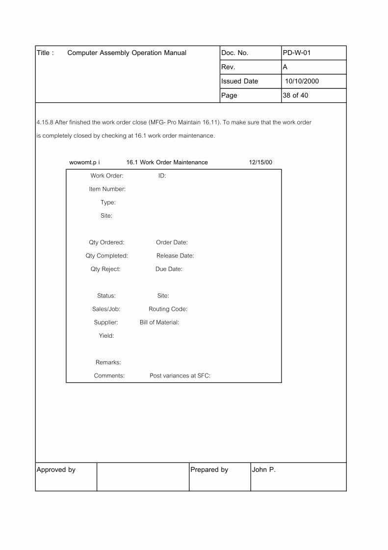
4.15.8 After finished the work order close (MFG- Pro Maintain 16.11). To make sure that the work order
is completely closed by checking at 16.1 work order maintenance.
wowomt.p i 16.1 Work Order Maintenance 12/15/00
Work Order: ID:
Item Number:
Type:
Site:
Qty Ordered: Order Date:
Qty Completed: Release Date:
Qty Reject: Due Date:
Status: Site:
Sales/Job: Routing Code:
Supplier: Bill of Material:
Yield:
Remarks:
Comments: Post variances at SFC:
Approved by Prepared by John P.
Title : Computer Assembly Operation Manual Doc. No. PD-W-01
Rev. A
Issued Date 10/10/2000
Page 39 of 40
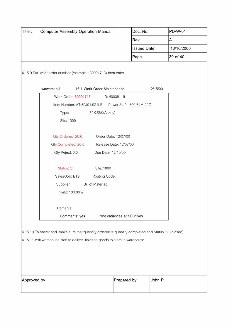
4.15.9 Put work order number (example : 30001713) then enter.
wowomt.p i 16.1 Work Order Maintenance 12/15/00
Work Order: 30001713 ID: 40038119
Item Number: AT.39J01.021LE Power Sx PIII800,64M,20G
Type: 52X,56K(Askey)
Site: 1000
Qty Ordered: 20.0 Order Date: 12/07/00
Qty Completed: 20.0 Release Date: 12/07/00
Qty Reject: 0.0 Due Date: 12/10/00
Status: C Site: 1000
Sales/Job: BTS Routing Code:
Supplier: Bill of Material:
Yield: 100.00%
Remarks:
Comments: yes Post variances at SFC: yes
4.15.10 To check and make sure that quantity ordered = quantity completed and Status : C (closed).
4.15.11 Ask warehouse staff to deliver finished goods to store in warehouse.
Approved by Prepared by John P.
Title : Computer Assembly Operation Manual Doc. No. PD-W-01
Rev. A
Issued Date 10/10/2000
Page 40 of 40
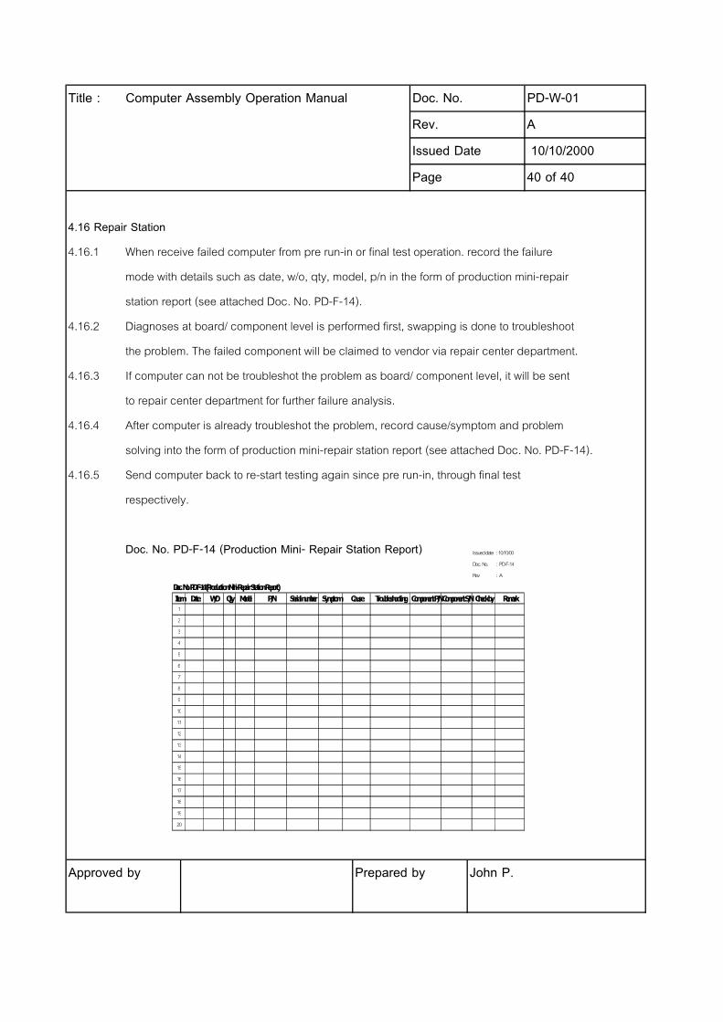
4.16 Repair Station
4.16.1 When receive failed computer from pre run-in or final test operation. record the failure
mode with details such as date, w/o, qty, model, p/n in the form of production mini-repair
station report (see attached Doc. No. PD-F-14).
4.16.2 Diagnoses at board/ component level is performed first, swapping is done to troubleshoot
the problem. The failed component will be claimed to vendor via repair center department.
4.16.3 If computer can not be troubleshot the problem as board/ component level, it will be sent
to repair center department for further failure analysis.
4.16.4 After computer is already troubleshot the problem, record cause/symptom and problem
solving into the form of production mini-repair station report (see attached Doc. No. PD-F-14).
4.16.5 Send computer back to re-start testing again since pre run-in, through final test
respectively.
Doc. No. PD-F-14 (Production Mini- Repair Station Report)
Approved by Prepared by John P.
Issued date : 10/10/00
Doc. No. : PD-F-14
Rev. : A
Doc. No. PD-F-14 (Production Mini-Repair Station Report)
Item Date W/O Qty Model P/N Serial number Symptom Cause Troubleshooting Component P/NComponent S/NCheck by Remark
1
2
3
4
5
6
7
8
9
10
11
12
13
14
15
16
17
18
19
20