Embed Size (px)
Citation preview
http://repository.osakafu-u.ac.jp/dspace/
Title Particle Movement In a Vertically Oscillating Liquid
Author(s) Tojo, Kakuji; Nishimura, Kiyohiko; Iwanaka, Hitoshi; Miyanami, Kei
Editor(s)
CitationBulletin of University of Osaka Prefecture. Series A, Engineering and nat
ural sciences. 1981, 30(1), p.41-53
Issue Date 1981-10-31
URL http://hdl.handle.net/10466/8345
Rights
41
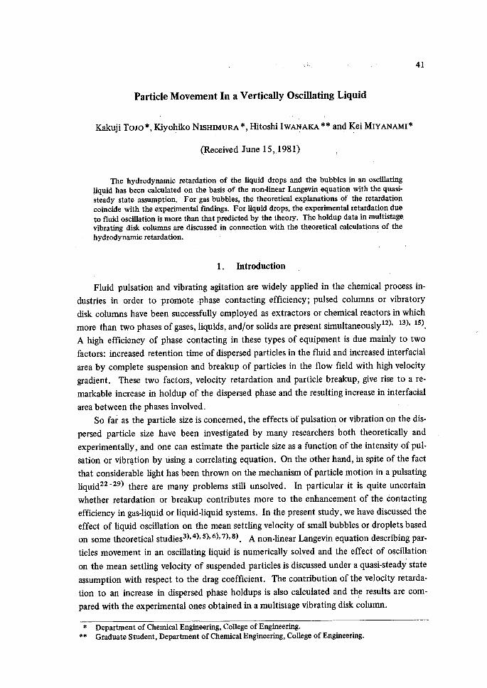
Particle Movement In a Vertically Oscillating Liquid
Kakaji ToJo *, Kiyohiko NisHiMuRA ", Hitoshi IwANAKA "" and Kei MiyANAMi"
(Received June 15, 1981)
The hydrodynamic retardation of the liquid drops and the bubbles in an oscillatingliquid has been calculated on the basis of the non-1inear Langgvin,equation with the quasi-
Ste'ady state assumption.'' For gas bubbles, the theoretical explanations of ' the retardation
coincide with the experimentai findings. For liquid drops, the experimental retardation due
to fluid oscillation is more than that predicted by the thgory. , The holdup data in multistage,
vibrating disk columms ,are discussed in connection with the theoretical calculations of the
hydrodynamic retardation.
1. lntroduction
Fluid pulsation and vibrating agitation are widely applied in the chemical process in-
dnstries in order to promote phase contacting efficiency;・ pulsed columns or vibratory
disk columns have been successfu11y employed as extractors or chemical reactors in which
more than two phases ofgases, liquids, and/or solids are present simultaneouslyi2), i3), i5).
A high efficiency of phase contacting in these types of equipment is due mainly to two
factors: increased retention time of dispersed particles in the fluid and increased interfacial
area by complete suspension and breakup of particles in the flow field with high velocity
gradient. These two factors, velocity retardation and particle breakup, give rise to a re-
markable increase in holdup of the dispersed phase and the resulting increase in interfacial
area between the phases involved.
So fat as the particle size is concerned, the effects ofpulsation or vibration on the dis-
persed particle size have been investigated by many researchers both theoretically and
experimentally, and one can estimate the particle size as a function of the intensity of pul-
sation or vibrqtion by using a correlating equation. On the other hand, in spite of the fact
that considerable light has been thrown on the mechanism of particle motion in a pulsating
liquid22-29) there are many problems still unsolved. In particular it is quite uncertain
whether retardation or breakup contributes more to the enhancement of the Contacting
efficiency in gas-liquid or liquid-liquid systems. In the present study, we have discussed the
effect of liquid oscillation on the mean settling velocity of smal1 bubbles or droplets based
on some theoretical studies3)'4)'5)'6)'7)'8). A non-linear Langevin equation describing par-
ticles movement in an oscillating liquid is numerically solved and the eflfbct of oscillation
on the mean settling velocity of suspended particles is discussed under a quasi-steady state
assumption with respect to the drag coefficient. The contribution ofthe velocity retarda-
tion to an increase in dispersed phase holdups is also calculated and th,t results are com-
pared with the experimental ones obtained in a multistage vibrating disk column.
* Department of Chemical Engineering, College of Engineering.
"" Graduate Student, Department of Chemical Engineering, College gf Engineering.
42 Kakoji TOJO, Kiyohiko NISHIMURA, Hitoshi IWANAKA and Kei MIYANAMI
2. Theory
The general differential equation for a spherical particle travelling in a straight line
through a viscous liquid at low Reynolds number was given by Basseti)' 2).
.(ddtu)=(.-.・)g-xm・ Z:+18dl !iua+9dM' g. (1)
・ j: F' (t - T) 1 V-;-dT
where m = mass of the particle, m' = mass of the liquid displaced by the particle, u =
velocity of the particle, x = coefficient of virtual mass, d = diameter of the particle, p =
density of the liquid, pt = viscosity of the liquid and F' = duldt. The first term in the right
hand Side of Eq. (1) is the gravitational force acting on the particle. The second term is the
resistance of a fluid to the accelerated motion of the particle. It is equivalent to an added
mass of the particle by the factor x of the mass of the liquid displaced. The third term is
the viscous resistance given by Stokes' law. The last term, called the Basset term, accounts
fbr the effect of the deviation in liquid flow pattern from steady state. If the particle is
situated in a liquid moving at the velocity of v, the equation ofmotion ofthe particle can
be obtained by replacing u in the right hand side of Eq. (1) by (u-v) as follows:
du dv (m +m'x) dt = (m -m')g+(1 + x) m' dt + 3ndu (u -v)
+-;-d2 vriibii S,` dV(St=iir$Ld ldt dt' (2)
The virtual mass coeflficient x for sinusoidally oscillating liquid equals to 1/2 at low Rey-
nolds number (Re < 1). The Basset theoretical treatment is limited to the particle motion
in a laminar flow field. In a turbulent flow field, on the other hand, very little is known
about the interaction between particle motion and turbulent agitation in the surrounding
fluid.
If the Stokes viscous term 3rrcijz (u-v) in Eq. (2) can be replaced by the equivalent
steady state expression for higher Reynolds number, Eq. (2) is rewritten as follows :
du dv vr (m +m'x) Tt =(m -m')g+(1 +x) m' -aTt + -g- CDd2p lu-vl",
sgn(u-v)+-;d2VliZEIS,tdVttt d"ldtdtt (3)
where n=1 for Re <1 andn=2 forRe > 1.
The velocity of a sinusoidally oscillating fluid is given by
v=2TAf cos (2 7fr). (4)For the case that a spherical particle rises through an oscillating liquid where a turbulent
flow field is fu11y deveioped, the virtual mass coefficent is assumed by
In the present study, the fundamental equation Eq. (3) is solved numerically by using a
tt
Particle Mbvement in a Vizrtically Oscillating Liquid 43
quasi-steady state approach, i.e., when the Basset term is zero and the drag coefficient can
be calculated from the instantaneous Reynolds nurnber (d i u - v I plpt).
The validity of the quasi-steady state assumption (QSSA) is supported by Shih et al.9),
and Keulegan et al.iO) who dealt with drag to oscillating flat plates, and found that the
coefficient of drag decreases with the period of oscillation, from a larger initial value to a
steady state one, they also found that when the period parameter, defined by
fer = umax 71W
is larger than about 10, the drag coefficient is almost independent of the period of oscilla-
tion. Here u..x, T and Ml are the maxlmum velocity of the plate, period of oscillation and
width of the plate, respectively. Therefore, it can be assumed that the developed flow is
established in an operational range of ,Per > 1O. If the plate width is taken as the particle
diameter d, the condition for developed flow is as follows:
"mm`zxi T.2'[A{l(ILf) >lo or : >l.sg (6)
In most cases of the present study, the value ofAld exceeds 2.0 and it seems reasonable to
assume the quasi-steady state approach.
Neglecting the transient component of the drag (the last term in Eq. (3)), we evaluate
the viscous term in Eq. (3) by the following relation:
(viscous term) =g CD d2p(u-v)2 sgn (u-v) (7)
where
241Re (10'` <Re<2.o)
CID= 18.5/71eO'6 (2.0<Re<500) (8) o.44 (s oo <Re <2× loS)for the solid particle in the fluid, and
5× 10'` Re+OA (400 <ReS700)
s.2 × 104 Re + o.17 (7oo <Re $ looo)
cb= ' ' (9) (looo <Re g 4ooo) 2.5 logio Re-6.5
2.55 (4000 <Re)for the gas bubble. Equation (8) is applied as an approximation to the liquid-liquid system
forRe < 1000 and the gas-liquid system forRe < 400ii).
3. Experimental
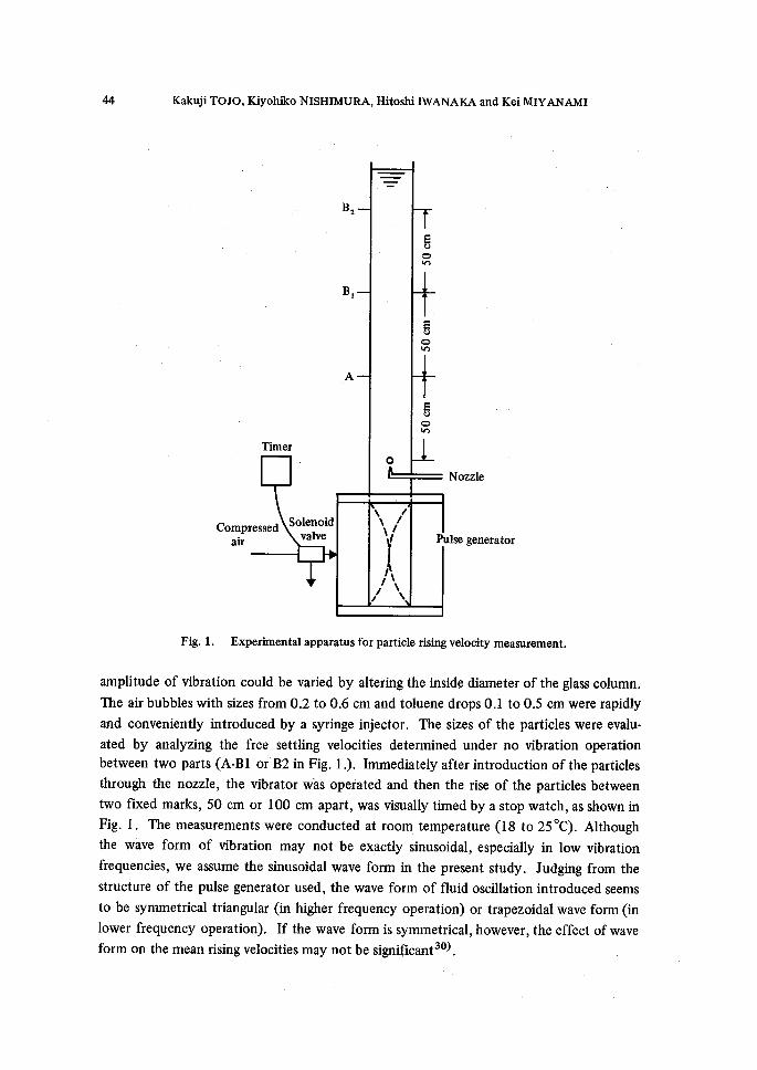
Experimental apparatus for measuring the mean settling velocity in an oscillating fluid
is shown in Fig. 1. Pyrex glass columns (5.0' cm, 2.8 cm and 2.5 cm I.D.) were used. The
fluid oscruation was introduced by using a compressed-air-triggered pulse generator. The
vibration was operated at frequencies from O to 3.5 Hz with amplitude up to 4.7 cm. The
" Kakoji TOJO, Kiyohiko NISHIMURA, Hitoshi IWANAKA and Kei MIYANAM!
Compressed air
gs
B,
B,ATimer
=-
o
g$gmo
N
Solenoidressedvalve
hls
Xlt
N/,11Nx
Nozzle
Pulse generator
Fig. 1. Experimental apparatus for particle rising velocity measurernent.
amplitude of vibration could be varied by altering the inside diameter of the glass column.
The air bubbles with sizes from O.2 to O.6 cm and toluene drops O.1 to O.5 crn were rapidly
and conveniently introduced by a syringe iajector. The sizes of the particles were evalu-
ated by analyzing the free settling velocities determined under no vibration operation
between two parts (A-Bl or B2 in Fig. 1 .). Immediately after introduction of the particles
through the nozzle, the vibrator w'as operated and then the rise of the particles between
two fixed marks, 50 cm or 1OO cm apart, was visually timed by a stop watch, as shown in
Fig. 1. The measurements were conducted at room, temperature (18 to 250C). Although
the wave form of vibration may not be exactly sinusoidal, especially in low vibration
frequencies, we assume the sinusoidal wave form in the present study. Judging from the
structure of the pulse generator used, the wave form of fluid oscillation introduced seems
to be symmetrical triangular (in higher frequency operation) or trapezoidal wave form (in
lower frequency operation). If the wave form is symmetrical, however, the effect of wave
form on the mean rising velocitiesmay not be significant30).
Pbrticle Mbvement in a Vlertically Oscillating Liquid 45
4. Results and Discussion
The trajectory and the mean rising velocity of a particle suspended in an oscillating
liquid were numerically calculated by using a digital computer. The Runge-Kutta-Gill
method was employed to solve Eq. (3) subject to the drag coefficient of Eqs. (8) or (9).
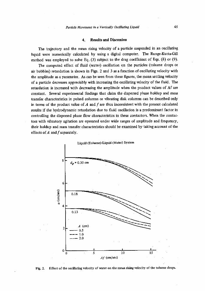
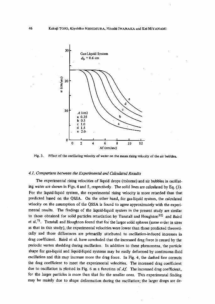
The computed effect of fiuid (water) oscillation on the particles (toluene drops or
air bubbles) retardation is shown in Figs. 2 and 3 as a function ofoscillating velocity with
the amplitude as a parameter. As can be seen from these figures, the paean settling velocity
of a particle decreases appreciably with increasing the oscillating velocity of the fluid. The
retardation is increased with decreasing the amplitude when the product values of Af are
constant. Several experimental findings that claim the dispersed phase holdup and mass
transfer characteristics in pulsed columns or vibrating disk columns can be described only
in terms of the product value ofA and f are thus inconsistent with the present calculated
results if the hydrodynamic retardation due to fluid oscillation is a predominant factor in
controlling the dispersed phase fiow characteristics in these contactors. When the contac-
tors with vibratory agitation are operated under wide ranges of amplitude and frequency,
their holdup and mass transfer characteristics should be examined by taking account of the
effects ofA andfseparately.
eq-g
g
8
6
4
2
o
Liquid (Toluene)-Liquid (Water) System
.
ctp = O.30 (rm a"".N.
'a= .-..
ls$:tstrNh)c"
NISItll:'s
NlllSNN
N
O.18
O.13
,"i --p -
A (cm)O.5
1.0
2.0
ts tsr ::-x
r5 )N "× NN':;lXN s
"$Eg-;r".xx.:×..NzlilN}-.NtNx'NNN
'"' -b
o 5 10 15
Af (cm/sec)
Fig. 2. Effect of the oscMating ・velocity of water on the mean rising velocity of the toluene drops.
46 Kakoji TOJO, Kiyoh'iko NISHIMURA, Hitoshi IWANAKA and Kei MIYANAMI
30
T$ 20xee"
10
o
Gas-Liquid System
db = O.6 (rm
A (cm)a O.25b O.5 ,
c 1.0d 1.5e 2.0-
・b
a
c
d
'e
O2 4 6 8 10 12 Af (cm/sec)
Fig. 3. Effect of the oscMating velocity of water on the mean rising velocity of the air bubbles.
4.1. Cbmparison between the Ebeperimental and thlculatedResults
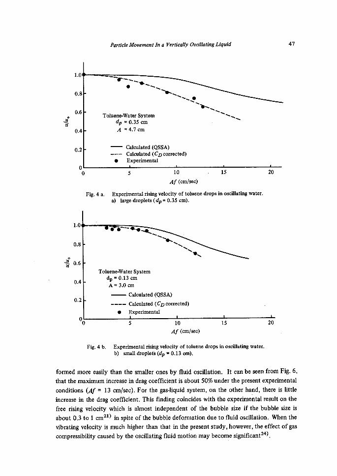
The experimental rising velocities of liquid drops (toluene) and air bubbles in oscillat-
ing water are shown in Figs. 4 and 5, respectively. The solid lines are calculated by Eq. (3).
For the liquid-liquid system, the experimental rising velocity is more retarded than that
predicted based on the QSSA. On the other hand, for gas-liquid system, the calculated
velocity on the assumption of the QSSA is fbund to agree approximately with the experi-
mental results. The findings of the liquid-liquid system in the present study are similar
to those obtained for solid particles retardation by Tunstall and Houghton22) and Baird
et al.7). Tunstall and Houghton fbund that fbr the larger solid spheres (same order in sizes
as that in this study), the experirnental velocities were lower than those predicted theoreti-
cally and those differences are primarilly attributed to oscillation-induced increases in
drag coeEficient. Baird et al. have concluded that the increased drag force is caused by the
periodic vortex shedding during oscillation. In addition to these phenomena, the particle
shape for gas-liquid and liquid-liquid systems may be easily deformed by continuous fluid
oscillation and this may increase more the drag force. In Fig. 4, the dashed line corrects
the drag coefficient to irieet the experimental velocities. The increased drag coeflficient
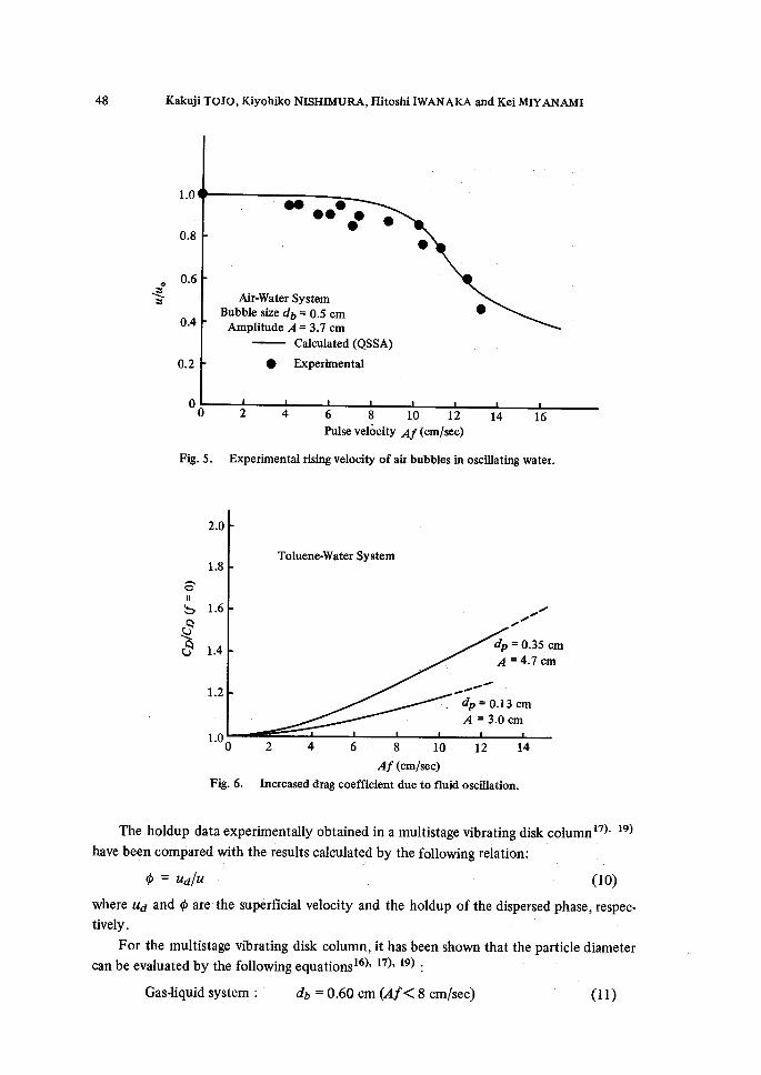
due to oscillation is plotted in Fig. 6 as a function of24r The increased drag coefficient,
for the larger particles is more than that for the smaller ones. This experimental finding
may be mainly due to shape deforrnation during the oscillation; the larger drops are de-
furticle Mbvement in a Vertically OsctllatingLiquid 47
eR"
1.0
O.8
O.6
O.4
O.2
o
--r-"NN e sx
Toluene-Water System db = O.35 cm
A =4.7 cm
--e-p-
e
N. N...NNxo NN
Calculated (QSSA)
Calculated (CD corrected)
Experimental
)NNNNNNN
o
Fig. 4 a.
5 10 , 15 Af (cm/sec)
Experimental rising velocity of toluene drops in oscillating water.
a) large droplets (di,= O.35 cm).
20
1.0
O.8
eg o.6
O.4
O.2
o
e e'-'b"t.q.
Toluene-Water System
dp = O.13 cm
A nt 3.0 cm
NNNe・・NNNN
Calculated (QSSA)
-・----・ Calculated (CID corrected)
e Experimental
-N
o 5 10
Af (cm/sec)
15 20
Fig. 4 b. Experimental rising velocity of toluene drops in oscMating water.
b) small droplefs (db = O.13 cm).
formed more easily than the smaller ones by fluid oscMation. It can be seen from Fig・ 6,
that the maximum increase in drag coefficient is about 50% under the present experimental
conditions (Af = 13 cmlsec). For the gas-liquid system, on the other hand, there is little
increase in the drag coefficient. This finding coincides with the experimental result on the
free rising velocity which is almost independent of the bubble size if the bubble size is
about O.3 to 1 cm2i) in spite of the bubble deformation due to fiuid oscillation. When the
vibrating velocity is much higlier than that in the present study, however, the effect ofgas
compressibility caused by the oscillating fluid motion may become significant24).
48 Kakilji TOJO, Kiyohiko NISHIMURA, Hitoshi IWANAKA and Kei MIYANAMI
1.0
O.8
O.6 eQ"
O.4
O.2
oo
eee e e
Air-Water SystemBubble size db = O.5 cm
Amplitude A = 3.7 cm
e Expe;imental
e
Calculated (QSSA)
e
e
Fig 5.
2 4 6 8 10 12 14 16 Pulse velocity Af(cmlsec) .
Experimental rising velocity of air'bubbles in oscMating water.
811
b
2.0
1.8
1.6g i.4
12
1.0
Toluene.Water System
/ / d2, = O.35 cm
A = 4.7 cm
-t'' .--. `lp = O.13 cm
A = 3.0 em
o
Fig. 6.
2 4 6・ 8 10 12 14 Af (cmlsec)Inereased drag coefficient due to fluid oscillation.
The holdup data expertmentally obtained in a multistage vibrating dis.k columni7), i9)
have been compared with the results calculated by the following relation:
where ud and ¢ are the superficial velocity and the holdup ofthe dispersed phase, respec-
' For the multistage vibrating disk column, it has been shown that the particle diameter
can be evaluated by the fo11owing equationsi6), i7), i9) ':
Gas-liquid system: db =O.60 cm (t4f<8 cm/sec) (1 1)
thrticle Mbvement in a Yiertically OscillatingLiquid 49
for the small vibrating disk column (di '-'- 5 cm), and
db = O.1 1 (ddldi)-i'2 mie"O・32 (2o < we < 4oo)
' ' 'fbr the large vibrating disk column (di = 17.2 cm).
Liquid-liquid systerr? :
dpldd = O.18 Mie'O'6 (vsie <o.e32BoO・834)
Bo = cGll A p glo = 2.46 (be > op32 BoO・834)
where
In order to estimate
disk column, the- by using smal1 styrene balls suspended in the column as a tracer
typical flow patterns.
alternately above and under the
ing disk column is substantially two dimensional
the emphasis
(12)
(13)
(14)
Jtie = dd (2 TAf)2 plo
dd = diameter of the vibrating disk,
p = density of the continuous phase ,
Ap = density difference between particle and fluid,
o = interfacial tension.
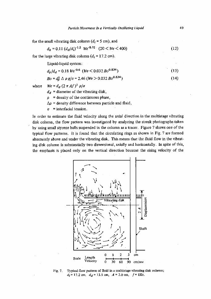
the fluid velocity along the axial direction in the multistage vibrating
flow pattern was investigated by analyzing the streak photographs taken
. Figute 7 shows' one of the
It is found that the circulating rings as shown in Fig.7 are formed
vibrating disk. This means that the fluid flow in the vibrat-
, axially and horizontally. In spite of this,
is placed only on the vertical direction because the rising velocity of the
.---.-xt!7Ne/Vg,.."llsilLN>-
=
l;:Ediii't"'llgil;ii"t'..,L.-.--'i-'Vinrasigdisk
fiirs311/ili2]-d--txe--'--X
(sl/s/ii./g・//.-・.l).xl,,).} :
=gs'e'a"Shaft
scale Length Velocity
l-・ny--・---+-ny--
O 30 60 90
cm
cm/sec
Fig. 7. Typical fiow pattern of fluid in a multistage vibrating disk column;
di = 17.2 cm, dd = 13.5 cm, A = 2.0 cm, f= IHz.
50 Kakilji TOJO, Kiyohiko NISHIMURA, Hitoshi IWANAKA and Kei MIYANAMI
particles is examined in the present study. The average values of amplitude and frequency
of flowing liquids are found to be dependent on the stage height, dh, the disk amplitude,
A and the disk frequency,f. Under the present operating conditons where the diameter
ratio between the disk and the column inside is O.6 to O.7, the average amplitude qf and
frequency ] e of the oscillating fiuid may be approximately given by the fo11owing relation:
dy = adh (cm)
G = 25 (Alclyr)f (1/sec)
where the value of coethcient a is O.35 for the small column of di -・- 5 cm and O.18 for the
large column of di = 17.2 cm respectively. The liquid flow pattern in the vibrating disk
column wi11 be shown in more detail elsewhere by the authors20).
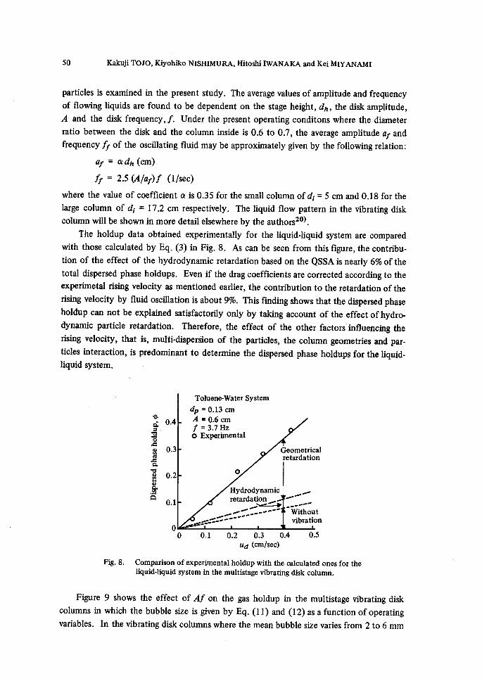
The holdup data obtained experimentally for the liquid-liquid system are compared
with those calculated by Eq. (3) in Fig. 8. As can be seen from this figure, the contribu-
tion of the effect of the hydrodynamic retardation based on the QSSA is nearly 6% of the
total dispersed phase holdups. Even if the drag coefficients are corrected according to the
experimetal rising velocity as mentioned earlier, the contribution to the retardation ofthe
rising velocity by fluid oscMation is about 9%. This finding shows that the dispersed phase
holdup can not be explained satisfactorily only by taking account of the effect ofhydro-
dynamic panicle retardation. Therefore, the effect of the other factors'influencing the
rising velocity, that is, multi-disperSion of the particles, the column geometries and par-
ticles interaction, is predominant to determine the dispersed phase holdups for the liquid-
liquid system.
scl O.4s.o
$ O.3.ce
za
v8 O.2o"
gh"
O.1
o
Toluene-Water System
db = O.13 cm
A = O.6 cmf = 3.7 Hzo Experimental
o
Geometricalretardation
Hydrodynamic retardation t7.t=t)v "f'-""-'"ts "t-'.....
-t'--d----. Without vibration
O O.1 O.2 O.3 O.4 O.5 ud (cm/sec)
Fig. 8. Comparison of experimental holdup with the calculated ones for the
liquid-liquid system in the multistage vibrating disk column.
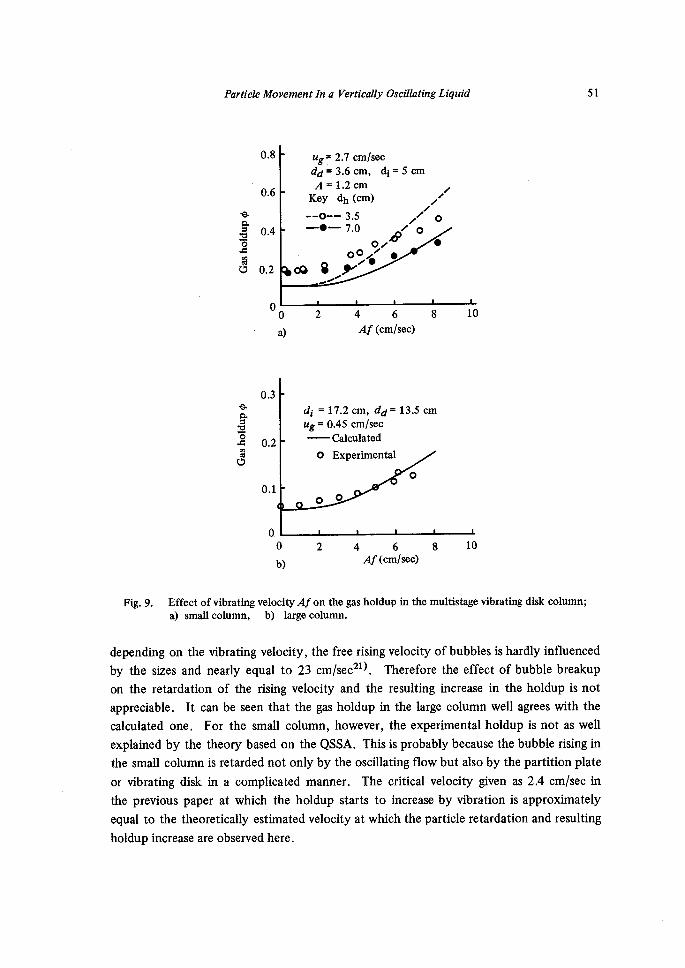
Figure 9 shows the effect of Af on the gas holdup in the multistage vibrating disk
columns in which the bubble size is given by Eq. (11) and (12) as a function of operating
variables. In the vibrating disk columns where the mean bubble size varies from 2 to 6 mm
POrticle Mbvement in a vaertically Oscillating Liquid 51
sasrzosree
O.8
O.6
O.4
O.2
o
ug= 2.7 cm/sec
dd= 3.6 cm, di =5 cm A = 1.2 crrn i Key dh (cm) / z ・--o-- 3.5 / o -ee 7'O o-s- O e
.g pOk-. -t--
o
a)
2
Af (cmlsec)
8 10
sasEo"reo
O.3
O.2
O.1
o.
di -- 17.2 cm, dd=
ug = O.45 cm/sec
Calculated
O Experimental
oo
13.5 cm
o
o
b)
2 Af (cm/sec)
10
Fig. 9. Effect ofvibrating velocity Af on the gas holdup in the multistage vibrating disk column;
a) smallcolumn, b) 1argecolumn.
depending on the vibrating velocity, the free rising velocity ofbubbles is hardly influenced
by the sizes and nearly equal to 23 cm/sec2i). Therefore the effect of bubble breakup
on the retardation of the rising velocity and the resulting increase in the holdup is not
appreciable. It can be seen that the gas holdup in the large column well agrees with the
calculated one. For the smal1 column, however, the experimental holdup is not as well
explained by the theory based on the QSSA. This is probably because the bubble rising in
the small column is retarded not only by the oscillating flow but also by the partition plate
or vibrating disk in a complicated manner. The critical velocity given as 2.4 cm/sec in
the previous paper at which the holdup starts to increase by vibration is approximately
equal to the theoretically estimated velocity at which the particle retardation and resulting
holdup increase are observed here.
52 Kakoji TOJO, KiyQhiko NISHIMURA, Hitoshi IWANAKA and Kei MIYANAMI
5. Conclusion
The particle settling velocity in an oscillating liquid has been calculated by numerically
integration of the non4inear Langevin equation with the assumption of the quasi-steady
state approach to elucidate the particle movement in a multistage vibrating disk column.
[[he findings obtained are as follows:
The extent of retardation of particle movement in the oscillating water is a function of
the amplitude A and the frequencyt Generally the higher the frequency, the more the
retardation occurs while the vibrating velocity A'f is kept to be constant. For a liquid-
liquid system, the rising velocity of the particle is decreased more than that calculated
based on the quasi-steady state assumption. This phenomenon is mainly attributed to the
drop shape defbrmation during oscillation and the resultant increase in drag force. The
effect of hydrodynamic retardation on the dispersed phase holdup increase for the liquid-
liquid system is less than 10% of the total holdups in the present study and the effect of
column internals, drops interaction and particle size dispersion on the dispersed phase
behavior in the column is found to be more significant. For gas-liquid system, the rising
velocity is approximately explained by the calculated hydrodynamic reterdation based on
the QSSA. By employing these findings, the gas holdup in a multistage vibrating disk
column is satisfactorily evaluated.
A=dy =Bo =CD =dd =dh =di =db =dp ='
d=f=ij =
g=m=m' =Per =
Re =
t=T=u=
Nomenclature
amplitude of oscillation or vibration, cm
amplitude of fluid oscillation in the MVDC, cm
modified Bond number, -
drag coefficient, -
diameter of vibrating disk, cm
height of the stage of the MVDC, cm
inside diameter of the column cm 'mean bubble diameter, cm
mean droplet diameter, cm
mean particle diameter, cm
frequency of oscillation or vibration,,Hz
frequency of fluid oscillation in the MVDC, Hz
gravitational constant, cm/sec2
mass of particle travelled through liquid medium, g
mass of continuous liquid displaced by particle, g
Period number, -
Reynolds number, -
trme sec ,period of oscillation, sec
velocity of the particle, cmlsec
Ptxrticle Mbvement in a Vertically Osclllating Liquld 53
uo =Ud =Ug =Umax
v=we =
pt =
p=Ap =
o=¢=X=
velocity of the particle without fiuid oscillation, cm/sec
superficial velocity of the dispersed liquid phase, cmlsec
superficial velocity of the gas phase, cm/sec
= maximum velocity of the vibrating plate, cm/sec
velocity of the oscillating fiuid, cm/sec
Weber number, dd (2 TAf)2 p/o
viscosity of the liquid, g cm/sec
density of the liquid, g/cm3
density difference, g/cm3
interfacial tension. glsec2
dispersed phase holdup, -
virtual mass coefficient, -
Referenoes
1)
2)
3)
4)
5)
6)
7)
8)
9)'10)
11)
12)
13)
14)
15)
16)
17)
18)
19)
20)
21)
22)
23)
24)
25)
26)
27)
28)
29)
30)
A. B. Basset, "A treatise on Hydrodynamics", XXII, Dover Reprint (1961).
H. Lamb, "Hydrodynamics", 6th edition, XI, Cambridge Univ. Press (1932).
C. M. Tchen, Ph. D. Thesis, Delft (1947), cited from ref. 4.
J. O. Hinze, "Turbulence", p.352, McGraw-HM, New York (1959).
G. Houghton, Proc. Roy. Soc., A272, 33 (1963).
W. B. Krantz, J. F. Carley and A. M. AL Taweel, Ind. Eng. Chem. Fundarn., 12, 391M. H. I. Baird, M. G. Senior and R. J. Thomson, Chem. Eng. Sci., 22, 551 (1967).
O. Molerus, Chem. Ing. Tech., 36,336 (1964).
C. C. Shih and H. J. Buchanan, J. Fluid Mech., 48, 229 (1971).
G. H. Keulegan and C. H. Carpenter, J. Roy. Bur. Standard, LX #5 , 423 (1958).
J. H. Perry and C. C. Chilton, Chem. Engrs' Handbook, 5th edition, pp.5-63 (1973).
T. Miyauchi and H. Ohya, AIChE J., 11, 395 (1965).
L. D. Smoot and A. L. Babb, Ind. Eng. Chem. Fundam., 1, 93 (1962).K. Tojo, K. Miyanami and T. Yano, J. Chem. Eng. Japan, 8, 122 (1975).
M. H. I. Baird and J. H. Garstang, Chem. Eng. ScL, 27, 823 (1972).
K. Miyanami, K. Tojo, T. Yano, K. Miyaji and I. Minami, Chem. Eng. Sci., 30, 1415 (1975).
K. Tctjo, K. Miyanami and T. Yano, J. Chem. Eng. Japan, 7, 126 (1974).
K. Tojo, K. Miyanami and T. Yano, to be submitted.
K. Miyanami, K. Tojo, I. Minarni and T. Yano, Chem. Eng. Sci., 33, 601 (1978).
K. TQjo, K. Miyanami, T. Nozue and T. Yano, to be submitted.
H. Kubota et aL, Kagaku Kougaku (Japan), 31, 1074 (1967).
E. B. Tunstall and G. Houghton, Chem. Eng. Sci., 23, 1067 (1968).
G. Houghton, Chem. Eng. Sci., 23, 287 (1968).
A. Marmour and E. Rubin, Can. J. Chem. Eng., 54, 509 (1976).
R. A. Herringe, Chem. Eng. J., 11, 89 (1976).
P. R. Schoneborn, Int. J. Multiphase Flow, 2, 307 (1975).
A. M. Al Toweel and J. F. Carley, Chem. Eng. Prog. Symp. Seri, 67 (116), 114 (1971).
E. Rubin, Can. J. Chem. Eng., 46, 145 (1968).
J. Molinier et al., Chem. Eng. Sci., 26, 1401 (1971).
K. Tojo and K. Miyanami, to be submitted.
(1973).