Embed Size (px)
Citation preview

1
TIN KNOCKER
S & DRIVE PLUS
INSTRUCTIONS & PARTS DIAGRAM
TAAG MACHINERY CO. (Master Distributor)
1257-B Activity Dr. Vista, CA 92081
Tel: (800) 640-0746 Fax: (760) 727-9948 Website: www.tinknocker.com * Email: [email protected]
01102007 mod 1
2
TIN KNOCKER
SAFETY RULES S & DRIVE PLUS
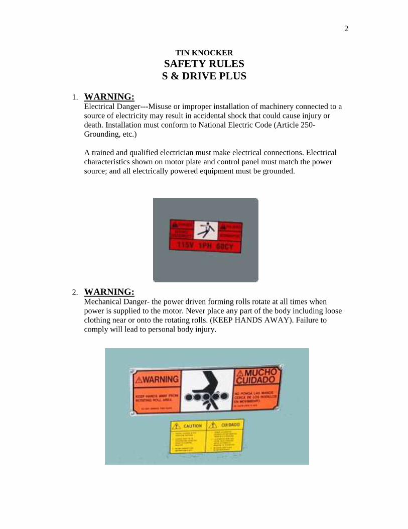
1. WARNING:
Electrical Danger---Misuse or improper installation of machinery connected to a source of electricity may result in accidental shock that could cause injury or death. Installation must conform to National Electric Code (Article 250-Grounding, etc.) A trained and qualified electrician must make electrical connections. Electrical characteristics shown on motor plate and control panel must match the power source; and all electrically powered equipment must be grounded.
2. WARNING: Mechanical Danger- the power driven forming rolls rotate at all times when power is supplied to the motor. Never place any part of the body including loose clothing near or onto the rotating rolls. (KEEP HANDS AWAY). Failure to comply will lead to personal body injury.

3
3. Never clean forming rolls while rolls are rotating—turn power off to clean rolls. 4. Machine to be operated by authorized personnel who have been trained by their
supervisor with the working and safety features of the machine, and by reading and understanding the Operator’s Manual.
5. Do not operate S & DRIVE PLUS without reading operator’s Manual and without proper supervisory instructions.
6. Perform all installation and set-up operations before applying power for electrical start-up.
7. Never operate machine with any guard removed; i.e., all required guarding to be installed and effective. Do not override the safety features of the equipment. Do not remove, paint over, alter, or deface any machine-mounted warning and instruction plates and signs.
8. Never leave machine running unattended. When not in use, turn off electrical power.
9. Never adjust machine with power on. Avoid accidental start-up. 10. Do not use machine if servicing is required. 11. Safety glasses and protective tools are recommended.
WARRANTY All new machines are sold with a one-year limited warranty, on factory defective parts. The warranty is limited to the original user. TAAG Machinery Co. at its option, will repair, replace or refund the purchase price of any part, tool or machine that fails during the warranty period. TAAG Machinery Co. will pay normal shipping charges for replacement parts. After 90 days from date of purchase, all express or overnight delivery charges are the responsibility of the customer. Purchaser must deliver to TAAG Machinery Co., at the address below, any written claim, with proof of original purchase. Replacement parts will be invoiced to purchaser and credit issued when the failed part is delivered to TAAG Machinery Co.. Removal, reinstallation or replacement parts shall be at purchasers’ / user’s expense. Failure due to improper use of the machine voids the warranty. NOTE: 1. This machine has been tested and adjusted prior to shipment, but can and often does require readjustment due to vibration and bouncing during transport. Following the procedures described within can easily do readjustment. These are procedures with which you, as a user, should be familiar, as you will use them repeatedly over the life use of the machine. If you have difficulty in performing these procedures, we are here to support you. Call us at: (800) 640-0746. 2. Opening rolls (for Philipsburg Lock) are consumable items and not subject to warranty.
TAAG MACHINERY CO. (Master Distributor)
1257-B Activity Dr. Vista, CA 92081
Tel: (800) 640-0746 Fax: (760) 727-9948 Website: www.tinknocker.com * Email: [email protected]

4
S & DRIVE PLUS Instructions
ELECTRICALS: 5 HP 230/460 volts three phase motor and controls, standard machine wired for 220 volt unless otherwise indicated. MACHINE SPECIFICATIONS:
“S” CLEAT
Capacity: 22 gauge galvanize or lighter Stock Width: 3-5/8” + 000-1/32 DRIVE CLEAT Capacity: 22 gauge galvanize or lighter Stock Width: 2-1/8” + 000-1/32
OPERATION: Start machine and place properly sheared material between gauge bars and feed material into the rolls. Check end results and make changes accordingly.
S & DRIVE PLUS Instructions / Trouble Shooting
ADJUSTMENTS:
Should the machine labor under load, the hold down studs is set too tight. To readjust, tighten the four studs that pass through the machine plates and then loosen approximately one-quarter turn (90’). Should machine continue to labor, loosen the two studs on the lead end of the machine to three-eights (135’), or one-half turn (180”) loose. Upward bow can be adjusted by lowering the exit adjusting screw located on the exit adjustment gauge assembly. Downward bow can be compensated by adjusting the hold down studs located at the exit end of the machine. Side bow is caused by an unbalanced stud adjustment.

5
LUBRICATION / MAINTAINCE: Lubrication fittings for the high-speed shafts are located under the stand auxiliary side panel. The high-speed bearings should be lubricated after every eight hours of operation (recommended lubricant-Standard Oil Viscous #3, or equivalent.)
Roll stations #4 and #5 are supplied with polished angle surface to eliminate friction and allow the material to flow smoothly during the forming sequence. The rolls should be lubricated periodically with an application of #20 or #30 SAE lubricating oil to insure a smooth sliding surface.
NOTE: If machine is to be used or stored out-of-doors, an oil or grease film will prevent rusting of surfaces. INSTRUCTIONS FOR AUXILIARY ROLLS: Machine auxiliary shafts are designed to accommodate various auxiliary roll sets listed below. To install these rolls, proceed as follows:
1. Remove machine cover. 2. Remove tabletop side plate, on side of machine that rolls are to be mounted. 3. If auxiliary rolls are now on machine, remove retaining bolts and washers.
Remove all parts not pertaining to the set to be used. 4. Place keys on shafts. 5. Select the first pair of rolls, which are marked “T-1” and “B-1” and place
them on the shafts at the entrance of the machine (Feed Side). Place the “T-1” roll on the upper shafts and “B-1” on the lower. Repeat procedure with roll stations #2, #3, and #4, etc. until all rolls have been mounted. All rolls marked “T” should be mounted on the top shafts and “B” rolls on the bottom shafts in numerical order. NUMBER SIDE OF ROLLS MUST FACE OUTWARD.
6. After rolls are installed, fasten rolls with retaining cap screws and washers. 7. Mount entrance and exit gauge bars to stand, using slotted holes provided in
stand table top and set entrance gauge by placing a straight edge along the outer edge of the auxiliary rolls; measure the required amounts in from this straight edge to the extreme ends of the entrance gauge bar. See schedule below for various auxiliary sets.

6
Auxiliary Roll Gauge Settings: A. 5/16” Auxiliary Pittsburgh (20 gauge and lighter) uses approximately 1” material.
Gauge Setting……………………………………………………………….1/11/19” to 1-3/4” A slight taper in gauge setting may be required, adjust gauge setting as needed.
NOTE: To install auxiliary opening roll holder, remove rolls from the #6 roll station and bolts that straddle the bottom 6 roll shafts (See Sketches #4 and #5). Place opening roll holder and slide on machine and fasten with the two ½- 13 x 2” Hex Head Cap Screws Provided.
B. Drive Cleat Auxiliary (20 gauge and lighter) uses 2-1/8” material. Gauge Setting………………………………………………2-1/8”
C. Combination 3-in-1 rolls (capacity 22 gauge and lighter), uses approx. 1-3/4” On “T” section, 1-1/8” on standing seam and ½” on right angle flange. Gauge Setting- 3-in-1 Gauge Bar: Top Step – “T” Section………………………………………2-1/16” Middle Step – Standing Seam…………………………………1-1/2” Bottom Step – Right Angle Flange……………………………15/16”
NOTE: When the first setting is made, the other two will automatically be correct. Placing material to the proper gauge step can make the other two shapes. The exit angle iron gauge has an adjustable bar that can be lowered to exert pressure on the material as it emerges from the rolls; thereby, straightening the finished section. See Sketch #3. NOTE: WHEN ADJUSTING THE EXIT GAUGE FROM THE 3-IN-1 COMBINATION, BE SURE TO SET IT TO THE “T” SECTION OR DAMAGE WILL RESULT BY MATERIAL INTERFERENCE WITH THE GAUGE BAR.
D. Female Button Punch Snap lock (20 to 24 gauge galvanize or optional 24 to 28 gauge) uses approx. 1-5/16” of material. Gauge Setting: 2-5/16” closest to forming rolls, 2-11/32” furthest from forming rolls. Taper may be increased or decreased as required for most satisfactory results.
Upward bow can be adjusted by rising or lowering the straightener roll located between stations 8 & 9.

7
NOTE: To install slide between stations 2 and 3, remove existing idler gear bolt and replace with longer bolt furnished with roll set.
E. Male Button Punch Snap lock (20 to 24 gauge galvanize or 24 to 28 gauge) uses approx. 7/16” of material. Gauge Setting……………………………………………………………15/16”
NOTES: 1. The S & Drive Plus is sold, standard, with S & Drive rolls and S Cleat slitter attachment. Empty shafts, opposite the Drive cleat rolls are available to accommodate the above (optional) auxiliary rolls. These shafts can also accommodate other (profile) rolls from Lock Former. 2. Remove existing bolts between Top 4 and 5 rolls and Top 5 and 6 rolls and replace with idler bracket and bolts provided with roll set. See Sketch #6 and #6A.

8
9
10
S” AND DRIVE CLEAT CUTTER ATTACHMENTS
Maximum Capacity of Unit: 22 Ga. Galv. (.0350” Material) Minimum Length of Cleat to be cut: 9” minimum
“S” AND DRIVE CLEAT CUTTER ATTACHMENT Operation Instructions
1. Check settings and make sure all mounting bolts are tight. 2. Start machine and place the material against the entrance gauge bar of the slitting attachment and feed the stock into the slitting rolls. The slit material will automatically deflect downward to the forming roll while the piece in the operator’s hand will deflect upward to clear the machine. The slitter will cut straight as long as the material, which has not gone thru the slitting rolls, is held against the entrance gauge bar. NOTE: WHEN RUNNING LONG SHEETS IT IS ADVISABLE THAT THE SHEET BE SUPPORTED AT APPROXIMATELY THE SAME HEIGHT AS THE SLITTING ATTACHEMENT ENTRANCE TABLE. ADJUSTMENT The slitter is properly adjusted and tested before shipment. Should the gauge accidentally become misaligned, refer to installation instructions paragraph 2. If the cleat runs out, or if material distribution is not correct, check the mounting of the attachment making sure the unit is mounted parallel to the machine side plates and settings are correct. When the slitting rolls need resharpening remove the bottom roll and grind it on the O.D. to remove any nicks and presents a clear sharp edge. The top roll has two cutting edges, when the resharpened lower roll is reinstalled, merely reverse the side of the roll presenting a new cutting edge. When ordering parts for this unit, please SPECIFY the SERIAL NUMBER of the machine. CAUTION: Machine will jam if pieces less than 9” are used. In case of jam-up, remove sheet deflector and remove material from unit.

11
3. Set slitting attachment on entrance table so that the spur gear of the attachment meshes with the gear of the No. 1 forming roll. Refer to Drawing No. 4 for set-up. Alternate Set-Up Procedure: Place Straight edge across the back of the slitter attachment casting and measure 7/32” from straight edge to machine plate. Take measurements at least 12” apart to insure slitter attachment is parallel to machine plate: Note: Entrance gauge bar is factory set and should not need adjustment. Setting is given for reference only. 3. Replace machine cover.

12

13
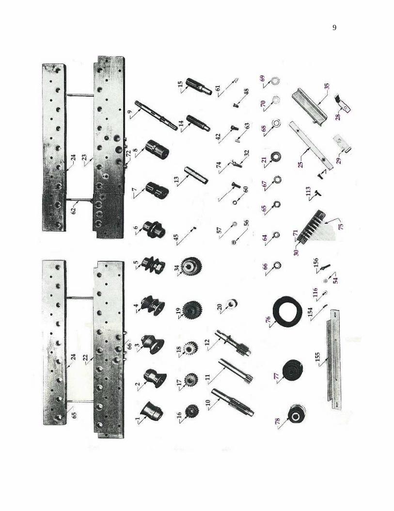
S & Drive Plus Parts List
Find No. part number Description PER
UNIT
1 MSDP11141 T-B1 2
2 MSDP11142 T-B2 2
3 MSDP11143 T-B3 2
4 MSDP11144 T-B4 2
5 MSDP11145 T-B5 2
6 MSDP11146 T-B6 2
7 MSDP11147 T-B7 2
8 MSDP11148 T-B8, T-B9 4
9 MSDP13128 Roll Shaft 18
10 MSDP13302 1st Drive Shaft 1
11 MSDP13304 2nd Drive Shaft 1
12 MSDP13406 3rd Drive Shaft 1
13 MSDP13505 Plain Spacer 13
14 MSDP13605 Idler Spacer 7
15 MSDP13657 Main Idler Spacer 1
16 MSDP14160 Drive Gear 18
17 MSDP14161 Idler Gear (takes 1-66090) 7
18 MSDP14162 Main Idler Gear (takes 2-66100) 1
19 MSDP14301 Drive Gear 1
20 MSDP14640 Collar 1
21 MSDP14661 Thrust Collar 2
22 MSDP20143 Btm. Frt. Plt. 1
23 MSDP20144 Btm. Plt. 1
24 MSDP20262 Upr. Bk. Plt. 2
25 MSDP21303 Ent. Ga. Bar 2
26 MSDP25676 Jack Base 2
27 MSDP29469 Motor Base 2
28 MSDP31907 Sheet Slide Gear 1
29 MSDP31908 Sheet Slide Roll 1
30 MSDP32902 Lube Conn Holder 1
31 MSDP37000 Grease Fitting Shim 2
32 MSDP42001 Lube Bolt 1
33 MSDP51084 Cover 1
34 MSDP51900 Fiber Gear Assy 1
35 MSDP53304 Exit Ga. Assy. 1
36 MSDP58509 Stand Complete 1

14
37 MSDP60052 5/16-18x1 Hex C.S. 1
38 MSDP60097 3/8-16x1-3/4 Hex C.S. 4
39 MSDP60166 1/2-13x3-1/2 Hex C.S. 2
40 MSDP60228 1/2-13x1-3/4 Hex C.S. 42
41 MSDP60402 3/8-16 1 SHCS 2
42 MSDP60450 1/2-13 1 SHCS 1
43 MSDP60575 10-24-3/8 RHMS 4
44 MSDP60593 10-32x7/16 F.H. Screw 2
45 MSDP60680 3/8-16 3/8 SSS 2
46 MSDP60875 3/8-16x1 CB 6
47 MSDP60877 3/8-16 1-3/4 CB 4
48 MSDP60954 1/2-13 1 FHSCS 4
49 MSDP61040 10 24 HN 4
50 MSDP61101 5/16-18 HN Hvy. SF 1
51 MSDP61120 3/8-16 HN Hvy. SF 6
52 MSDP61122 3/8-16 HN Fin. 4
53 MSDP61160 1/2-13 HN Hvy. SF 6
54 MSDP61300 3/8-16 Jam Nut SF 4
55 MSDP62026 3/8x.052 Washers 4
56 MSDP62340 3/8 Blvl Washer 48
57 MSDP62029 3/8-1/16 Washer 18
58 MSDP62360 3/16 Lockwashers 3
59 MSDP62363 3/8 Lockwashers 12
60 MSDP62364 1/2 Lockwashers 43
61 MSDP62402 15 wdrd Key 39
62 MSDP62551 3/8-16 6-1/2 Stud 4
63 MSDP62633 3/8-1 Dwl 4
64 MSDP66090 B1416 Torr Brg. 7
65 MSDP66100 B1612 Torr Brg. 38
66 MSDP66111 HJ162412 Torr Brg. 6
67 MSDP66320 NTA 1625 Torr Brg. 2
68 MSDP66321 1-3/32 washer HT 2
69 MSDP66422 TT1503 2 Thrust Brg. 7
70 MSDP66425 TT1709 1 Thrust Brg. 42
71 MSDP66600 886L Fem Couplg. 7
72 MSDP66610 888L Half Union 7
73 MSDP66640 1610 Grs. Fitting 7
74 MSDP66650 Angle Body 1
75 MSDP66700 Tubing 121
76 MSDP70052 5L 480 Belt 2
77 MSDP70421 2 BK 32 1 Shv. 1

15
78 MSDP70442 2 BK 45 1-1/8 Shv. 1
79 MSDP80080 5 HP 3 60 1800 184 1
80 MSDP80103 Mtr. Control 1
81 MSDP80423 BX Cable 12 3 58 1
82 MSDP80483 BX Conn. 3/8 1
83 MSDP80601 Rg. Fng. Terminal 3
84 MSDP80928 Back Enclosure 1
85 MSDP82254 Heater Element 2
86 MSDP11711 Bottom Slitting Roll 1
87 MSDP11712 Top Slitting Roll 1
88 MSDP13105 Bottom Roll Shaft 1
89 MSDP13106 Top Roll Shaft 1
90 MSDP14150 Drive Gear 2
91 MSDP14171 Idler Gear 2
92 MSDP14226 Clutch, Gear 1
93 MSDP19326 Idler Stud 2
94 MSDP21304 Entrance Gauge 1
95 MSDP30902 Washer 1
96 MSDP34700 Defl. Guard 1
97 MSDP35322 Cover Plate 1
98 MSDP35902 Wear Plate 1
99 MSDP35979 Template 1
100 MSDP39950 Thrust Washer 1
101 MSDP40250 Main Housing 1
102 MSDP44021 Thrust Washer 1
103 MSDP56574 Deflector 1
104 MSDP56575 Entrance Table 1
105 MSDP60045 5/16-18 x 1/2 HHCS 2
106 MSDP60090 3/8-16x3/4 Hex Cap Screw 4
107 MSDP60093 3/8-16x1 Hex HD Cap Screw 1
108 MSDP60102 3/8-16x5" Lg. Hex. Capscrew 2
109 MSDP60498 5/16-18x3/8 SHCS 1
110 MSDP60571 8-32x3/4" RHMS 2
111 MSDP60576 10-24x1/2" Lg. Rd. Hd. Mach. Screw 4
112 MSDP60795 4x3/16 Drive Scr. 2
113 MSDP60876 3/8-16x1-1/4 CB 3
114 MSDP60877 3/8-16x1-3/4" Lg. Carriage Bolt 2
115 MSDP61020 8-32 Hex Nut 2
116 MSDP61120 3/8-16 Hex. Nut 2
117 MSDP62002 3/16x.049 Wsr. 2
118 MSDP62029 3/8 ID Plain Washer 2

16
119 MSDP62301 "C" Washer 2
120 MSDP62360 3/16 Lockwashers 4
121 MSDP62363 3/8 Lockwashers 5
122 MSDP62420 3/16 Sq. Key
123 MSDP62424 3/16 Sq. Key 1/2 1
124 MSDP62502 Retaining Ring 3
125 MSDP66080 Bearing 2
126 MSDP66100 Bearing 4
127 MSDP66421 Thrust Washer 2
128 MSDP66422 Thrust Washer 4
129 MSDP66425 Thrust Washer 1
130 MSDP66430 TT150-2 Brg. 1
131 MSDP66500 Clutch 1
132 MSDP71154 1" Collar 1
133 MSDP42401 Special Key 2
134 MSDP66110 Clutch Bearing (RCB 162117) 1
135 MSDP99001 Set of Pitts Rolls Kit
136 MSDP99002 Set of 3 in 1 Rolls Kit
137 MSDP99003 Set of Male Button Lock Rolls (20 - 24 gauge) Kit
138 MSDP99004 Set of Female Button Lock Rolls (20 - 24 gauge) Kit
139 MSDP99005 Set of Male Button Lock Rolls (24 - 28 gauge) Kit
140 MSDP99006 Set of Female Button Lock Rolls (24 - 28 gauge) Kit
141 MSDP99007 Cabinet / complete with hood and guides
142 MSDP99008 Hood for cabinet
143 MSDP99009 Switch 30 AmpLGMCCB single phase
144 MSDP99010 Cover Plate single phase
145 MSDP99011 Switch 30 Amp mounting box single phase
146 MSDP99012 Switch 30 Amp mounting box Link single phase
147 MSDP99013 Switch 15 AmpLGMCCB 3 phase
148 MSDP99014 Cover Plate 3 phase
149 MSDP99015 Switch 15 Amp mounting box 3 phase
150 MSDP99016 Switch 15 Amp mounting box Link 3 phase
151 MSDP99017 Complete Slitter including hardware
152 MSDP99018 7.5 Hp 1 phase motor granger part number 5K677
153 MSDP99019 Two Groove Sheave for 71/2 hp motor granger part number 5k677
154 MSDP99020 3/8 Stove Bolts 4
155 MSDP99021 Motor Mounts 2
156 MSDP99022 3/8 Stove Bolts 4
157 MSDP99023 S&DP Drive cleat roll Kit 1
158 MSDP99024 S&DP Drive cleat Entrance Guide 1
159 MSDP99025 S&DP Drive cleat Exit Guide 1

17
160 MSDP99026 S&DP Drive cleat Defector 1
161 MSDP99027 T-1 Drive Cleat Roll 1
162 MSDP99028 T-2 Drive Cleat Roll 1
163 MSDP99029 T-3 Drive Cleat Roll 1
164 MSDP99030 T-4 Drive Cleat Roll 1
165 MSDP99031 T-5 Drive Cleat Roll 1
166 MSDP99032 T-6 Drive Cleat Roll 1
167 MSDP99033 T-7 Drive Cleat Roll 1
168 MSDP99034 T-8 Drive Cleat Roll 1
169 MSDP99035 T-9 Drive Cleat Roll 1
170 MSDP99036 B-1 Drive Cleat Roll 1
171 MSDP99037 B-2 Drive Cleat Roll 1
172 MSDP99038 B-3 Drive Cleat Roll 1
173 MSDP99039 B-4 Drive Cleat Roll 1
174 MSDP99040 B-5 Drive Cleat Roll 1
175 MSDP99041 B-6 Drive Cleat Roll 1
176 MSDP99042 B-7 Drive Cleat Roll 1
177 MSDP99043 B-8 Drive Cleat Roll 1
178 MSDP99044 B-9 Drive Cleat Roll 1
179 MSDP99045 S&DP Drive cleat Defector bolts 4
180 MSDP99046 S&DP Drive cleat Defector lock washers 4
181 MSDP99047 Moonwasher 18
182 MSDP99048 Bolts (roll retaining) 18
183 MSDP99049 Flat washer (roll retaining) 18
184 MSDP99050 Carriage Bolt for (Entrance / Exit Guide) 4
185 MSDP99051 Lockwasher for (Carriage Bolt) 4
186 MSDP99052 Nut for (Carriage Bolt) 4
187 MSDP99053 Key 18