Embed Size (px)
Citation preview
TKT-2431 SoC DesignLec 12 – On-chip communication
Erno Salminen
Department of Computer SystemsTampere University of Technology
Fall 2012
Erno Salminen - Dec. 2012
#2/52
Copyright notice Part of the slides adapted from slide set
by Timo D. Hämäläinen Managing On-Chip Chip Communications, SoC Symposium, Tampere
19.11.2003
Part of the figures and tables from L. Benini, G. De Micheli, Networks on chips: a new SoC
paradigm, Computer, Vol. 35, Iss. 1, Jan. 2002, pp. 70 -78. V. Lahtinen, Design and Analysis of Interconnection
Architectures for On-Chip Digital Systems, PhD Thesis, Tampere University of Technology, Department of Information Technology, June 2004. http://www.tkt.cs.tut.fi/research/daci/pub_open/lahtinen_thesis.pdf
Wolf, W.; Jerraya, A.A.; Martin, G.; , "Multiprocessor System-on-Chip (MPSoC) Technology," Computer-Aided Design of Integrated Circuits and Systems, IEEE Transactions on, vol.27, no.10, pp.1701-1713, Oct. 2008
Erno Salminen - Dec. 2012
#3/52
ContentsProblem statementPhysical limitationsNetwork-on-chip (NoC)
Extra stuff for the examSee also: E. Salminen, A. Kulmala, T.D. Hämäläinen, "Survey of Network-on-chip Proposals", white
paper, OCP-IP, [online]: http://www.ocpip.org/socket/whitepapers/OCP-IP_Survey_of_NoC_Proposals_White_Paper_April_2008.pdf, April 9, 2008, 13 pages.
E. Salminen, "On Design and Comparison of On-Chip Networks", PhD Thesis, Tampere University of Technology, Publication 872, 2010, 230 pages. Available: http://dspace.cc.tut.fi/dpub/handle/123456789/6543
Erno Salminen - Dec. 2012
#4/52
At first
Make sure that simple things work before even trying more complex ones
Erno Salminen - Dec. 2012
#5/52
SoC
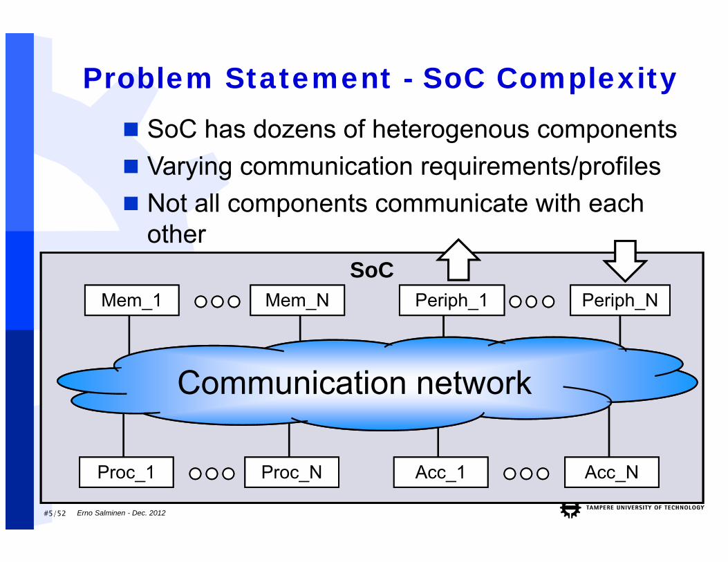
Problem Statement - SoC Complexity
Communication network
SoC has dozens of heterogenous components Varying communication requirements/profiles Not all components communicate with each
other
Mem_1 Mem_N
Proc_1 Proc_N Acc_1 Acc_N
Periph_1 Periph_N
Erno Salminen - Dec. 2012
#6/52
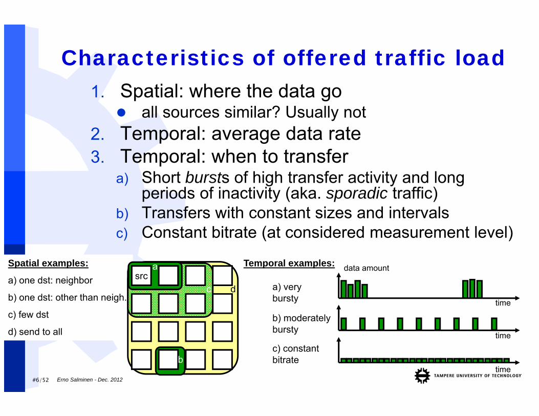
Spatial examples:
a) one dst: neighbor
b) one dst: other than neigh.
c) few dst
d) send to all
b
Characteristics of offered traffic load1. Spatial: where the data go
all sources similar? Usually not2. Temporal: average data rate3. Temporal: when to transfer
a) Short bursts of high transfer activity and long periods of inactivity (aka. sporadic traffic)
b) Transfers with constant sizes and intervalsc) Constant bitrate (at considered measurement level)
time
a) very bursty
time
b) moderately bursty
data amountsrc
Temporal examples:
b
a
c d
time
c) constant bitrate
Erno Salminen - Dec. 2012
#7/52
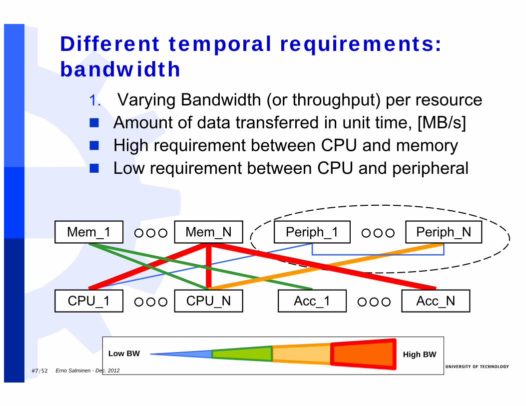
Different temporal requirements: bandwidth
1. Varying Bandwidth (or throughput) per resource Amount of data transferred in unit time, [MB/s] High requirement between CPU and memory Low requirement between CPU and peripheral
Mem_1 Mem_N Periph_1 Periph_N
CPU_1 Acc_NCPU_N Acc_1
High BWLow BW
Erno Salminen - Dec. 2012
#8/52
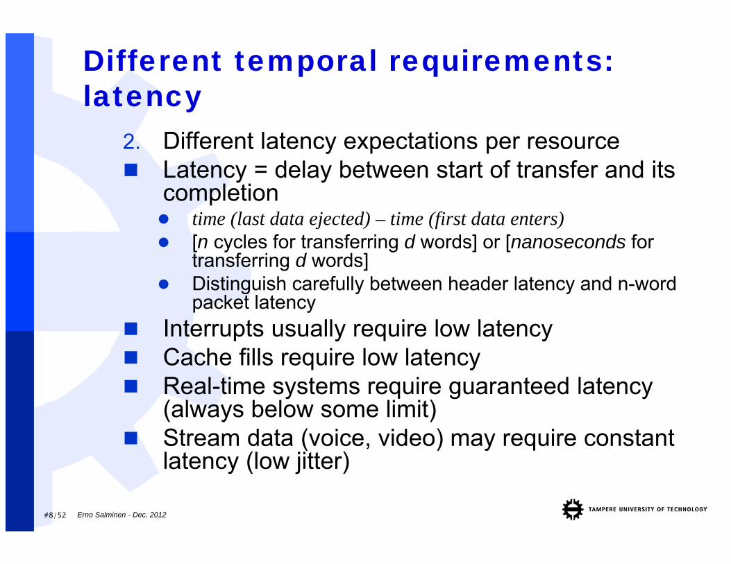
Different temporal requirements: latency
2. Different latency expectations per resource Latency = delay between start of transfer and its
completion time (last data ejected) – time (first data enters) [n cycles for transferring d words] or [nanoseconds for
transferring d words] Distinguish carefully between header latency and n-word
packet latency Interrupts usually require low latency Cache fills require low latency Real-time systems require guaranteed latency
(always below some limit) Stream data (voice, video) may require constant
latency (low jitter)
Erno Salminen - Dec. 2012
#9/52
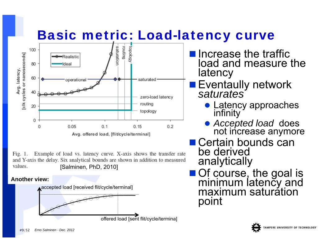
Basic metric: Load-latency curve Increase the traffic
load and measure the latency
Eventaully networksaturates Latency approaches
infinity Accepted load does
not increase anymoreCertain bounds can
be derivedanalytically
Of course, the goal is minimum latency and maximum saturationpoint
[Salminen, PhD, 2010]
accepted load [received flit/cycle/terminal]Another view:
offered load [sent flit/cycle/termina]
Erno Salminen - Dec. 2012
#10/52
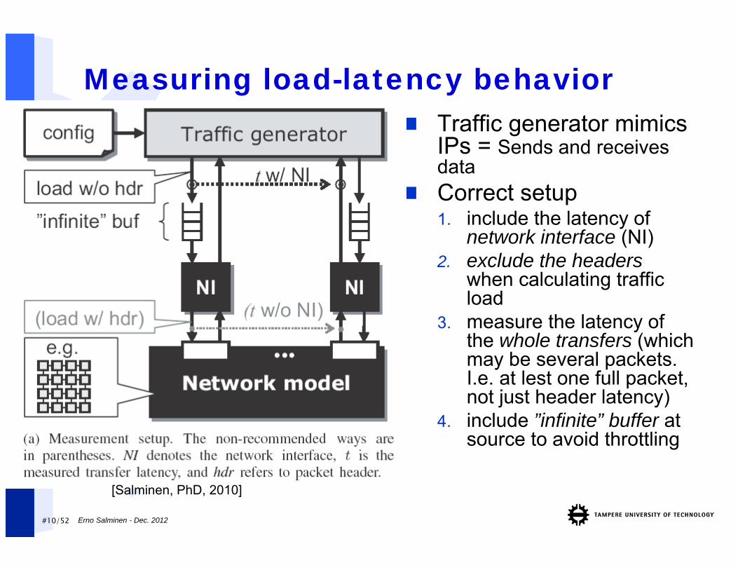
Measuring load-latency behavior Traffic generator mimics
IPs = Sends and receivesdata
Correct setup1. include the latency of
network interface (NI)2. exclude the headers
when calculating trafficload
3. measure the latency of the whole transfers (whichmay be several packets. I.e. at lest one full packet, not just header latency)
4. include ”infinite” buffer at source to avoid throttling
[Salminen, PhD, 2010]
Erno Salminen - Dec. 2012
Physical limitations of interconnects
Erno Salminen - Dec. 2012
#12/52
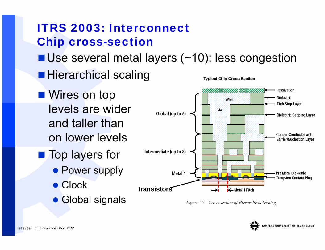
ITRS 2003: InterconnectChip cross-section
transistors
Wires on top levels are wider and taller than on lower levels
Top layers for Power supply Clock Global signals
Use several metal layers (~10): less congestionHierarchical scaling
Erno Salminen - Dec. 2012
#13/52
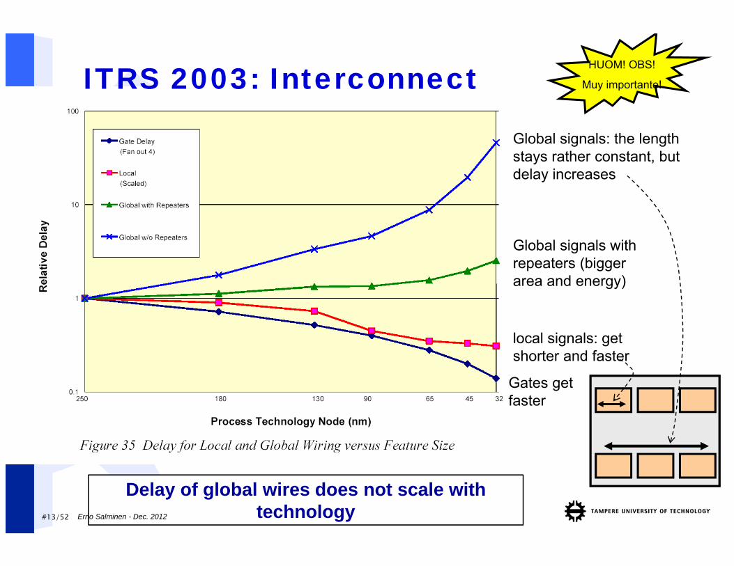
ITRS 2003: Interconnect
Delay of global wires does not scale with technology
Gates getfaster
local signals: getshorter and faster
Global signals with repeaters (biggerarea and energy)
Global signals: the lengthstays rather constant, butdelay increases
HUOM! OBS!
Muy importante!
Erno Salminen - Dec. 2012
#14/52
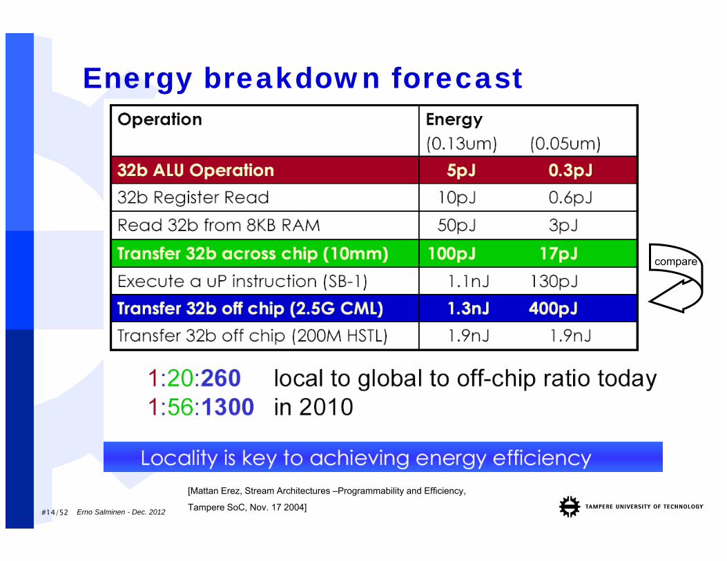
Energy breakdown forecast
[Mattan Erez, Stream Architectures –Programmability and Efficiency,
Tampere SoC, Nov. 17 2004]
compare
Erno Salminen - Dec. 2012
#15/52
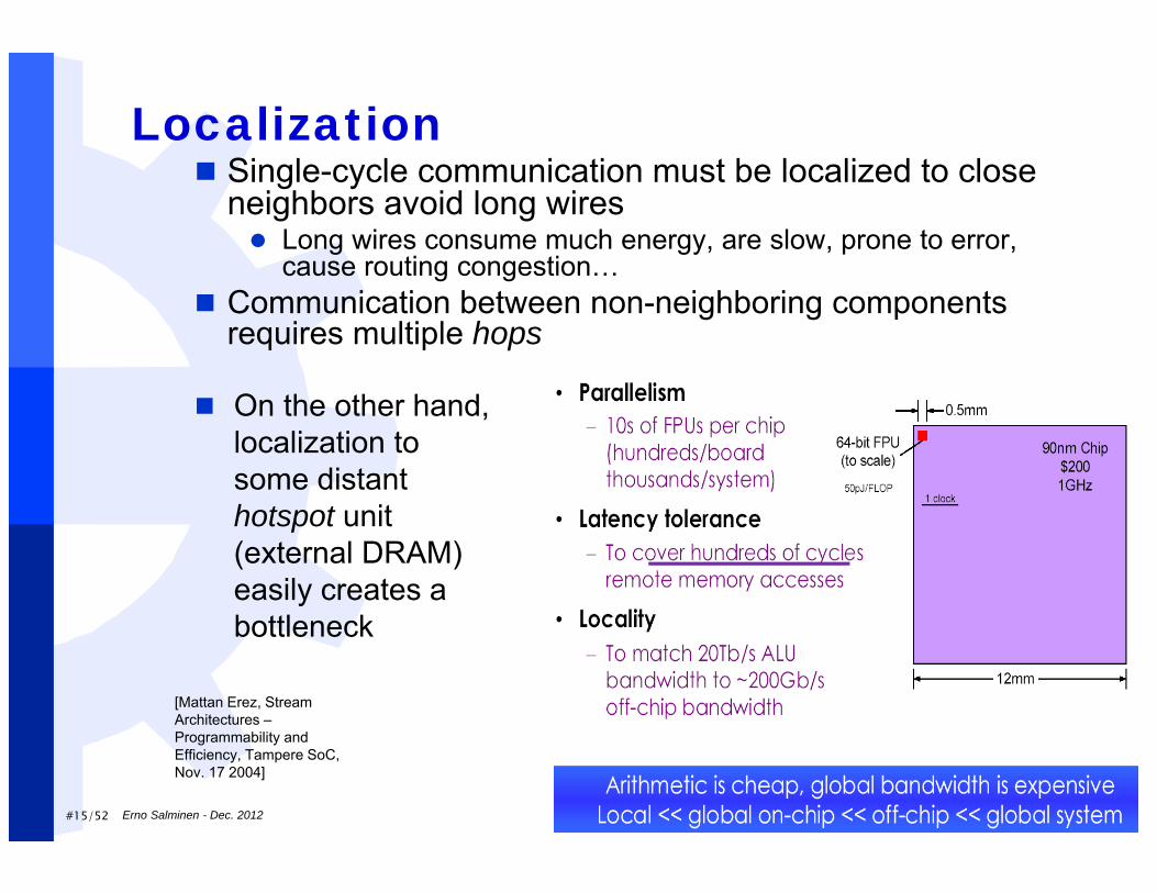
Localization
[Mattan Erez, Stream Architectures –Programmability and Efficiency, Tampere SoC, Nov. 17 2004]
Single-cycle communication must be localized to close neighbors avoid long wires Long wires consume much energy, are slow, prone to error,
cause routing congestion… Communication between non-neighboring components
requires multiple hops
On the other hand, localization to some distant hotspot unit (external DRAM) easily creates a bottleneck
Erno Salminen - Dec. 2012
#16/52
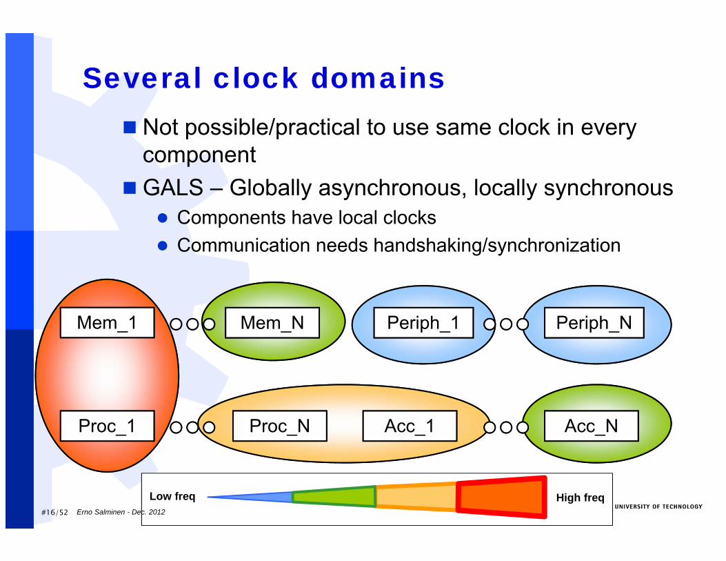
Several clock domains Not possible/practical to use same clock in every
componentGALS – Globally asynchronous, locally synchronous
Components have local clocks Communication needs handshaking/synchronization
Mem_1 Mem_N
Proc_1 Proc_N
Periph_1 Periph_N
Acc_1 Acc_N
High freqLow freqErno Salminen - Dec. 2012
#17/52
Reliability problems ”Synchronization failures between clock
domains will be rare but unavoidable” - BeniniElectrical noise due to crosstalk,
electromagentic interference, radiation...Data errors or upsets, soft errorsData transfers become unreliable and
nondeterministicDesign needs both deterministic and
stochastic models
Erno Salminen - Dec. 2012
#18/52
Achieving reliability Today, designers use physical techniques to
overcome reliability problems Wire sizing Length optimization Repeater insertion Shielding Data coding Bunch of others...Huge design effort required
In (near) future, 100% reliability on physical level cannot be afforded anymore
Reliability muts be increased with additional HW or SW layers Error detecting/correcting codes Retransmissions
Request/acknowledge and time-out counters
Erno Salminen - Dec. 2012
#19/52
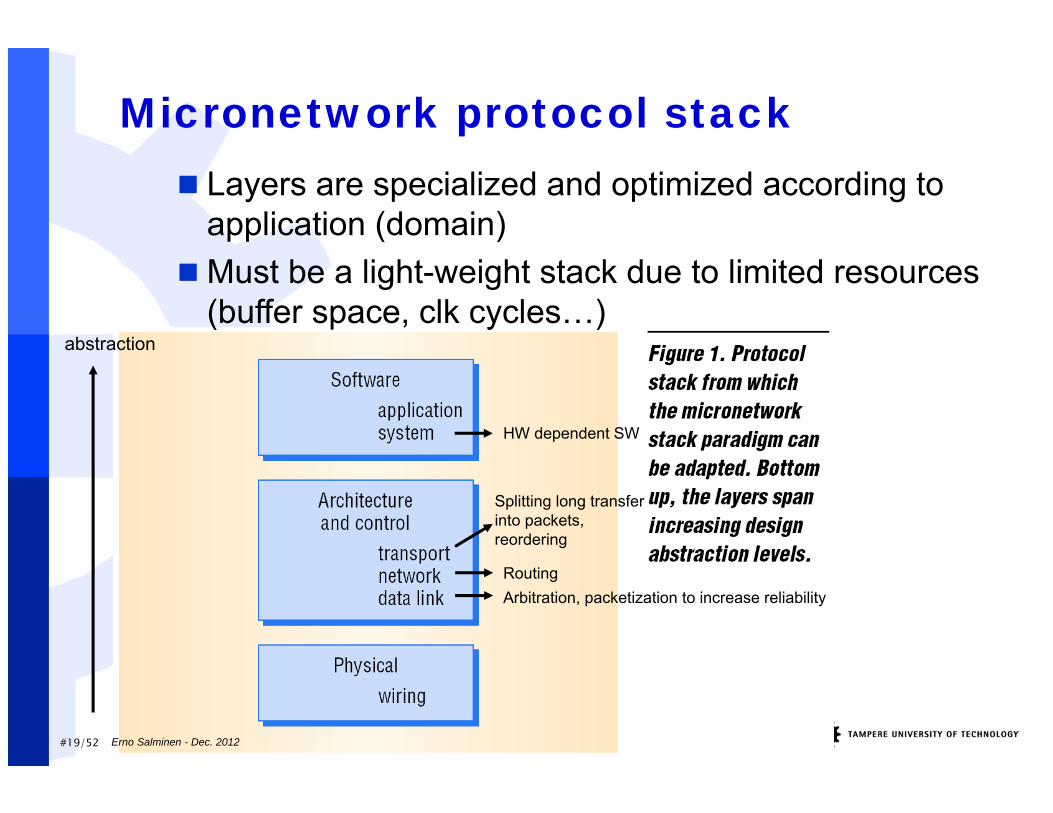
Micronetwork protocol stack Layers are specialized and optimized according to
application (domain)Must be a light-weight stack due to limited resources
(buffer space, clk cycles…)abstraction
Arbitration, packetization to increase reliabilityRouting
Splitting long transfer into packets, reordering
HW dependent SW
Erno Salminen - Dec. 2012
Network-on-chip (NoC)
Erno Salminen - Dec. 2012
#21/52
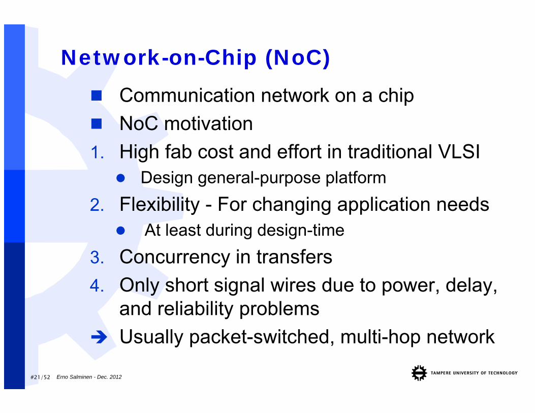
Network-on-Chip (NoC) Communication network on a chip NoC motivation1. High fab cost and effort in traditional VLSI Design general-purpose platform
2. Flexibility - For changing application needs At least during design-time
3. Concurrency in transfers4. Only short signal wires due to power, delay,
and reliability problems Usually packet-switched, multi-hop network
Erno Salminen - Dec. 2012
#22/52
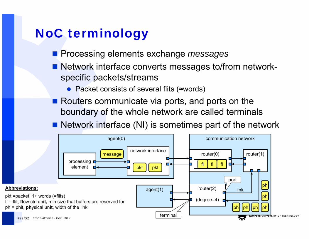
Abbreviations:pkt =packet, 1+ words (=flits)fl = flit, flow ctrl unit, min size that buffers are reserved forph = phit, physical unit, width of the link
agent(0)
processing element
NoC terminology
communication network
network interfacerouter(0) router(1)
router(2)
(degree=4)
agent(1) link
message
pktpkt
ph
fl fl fl
ph
port
ph
ph
ph
ph
terminal
Processing elements exchange messages Network interface converts messages to/from network-
specific packets/streams Packet consists of several flits (≈words)
Routers communicate via ports, and ports on the boundary of the whole network are called terminals
Network interface (NI) is sometimes part of the network
Erno Salminen - Dec. 2012
#23/52
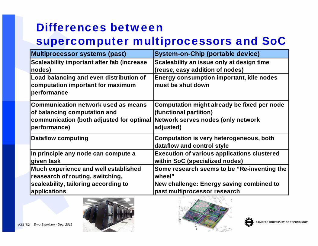
Differences betweensupercomputer multiprocessors and SoC
Multiprocessor systems (past) System-on-Chip (portable device)Scaleability important after fab (increase nodes)
Scaleability an issue only at design time (reuse, easy addition of nodes)
Load balancing and even distribution of computation important for maximum performance
Energy consumption important, idle nodes must be shut down
Communication network used as means of balancing computation and communication (both adjusted for optimal performance)
Computation might already be fixed per node (functional partition) Network serves nodes (only network adjusted)
Dataflow computing Computation is very heterogeneous, both dataflow and control style
In principle any node can compute a given task
Execution of various applications clustered within SoC (specialized nodes)Some research seems to be ”Re-inventing the wheel” New challenge: Energy saving combined to past multiprocessor research
Much experience and well established reasearch of routing, switching, scaleability, tailoring according to applications
Erno Salminen - Dec. 2012
#24/52
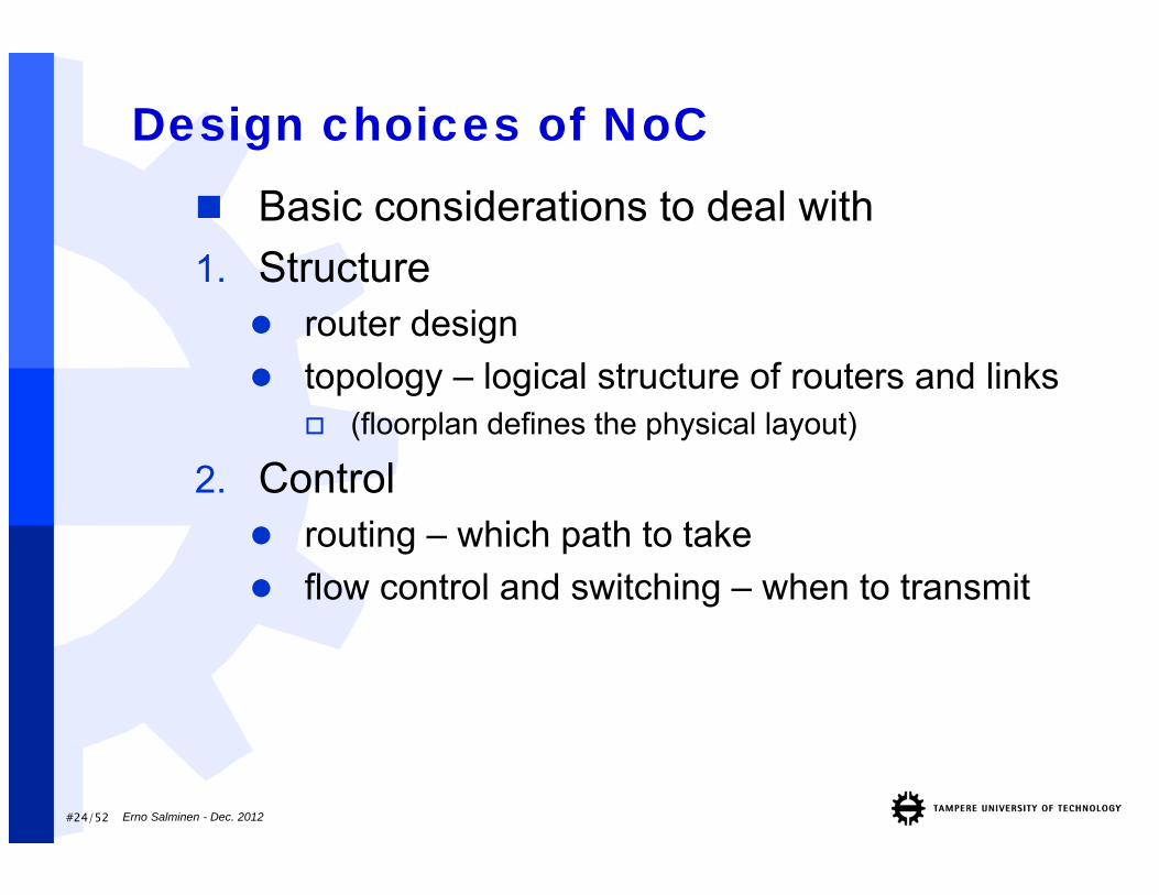
Design choices of NoC Basic considerations to deal with1. Structure router design topology – logical structure of routers and links
(floorplan defines the physical layout)
2. Control routing – which path to take flow control and switching – when to transmit
Erno Salminen - Dec. 2012
#25/52
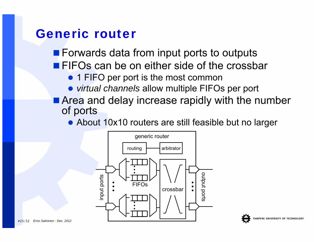
Generic router
generic router
......
inpu
t por
tsoutput ports...
routing arbitrator
FIFOscrossbar
...
Forwards data from input ports to outputsFIFOs can be on either side of the crossbar
1 FIFO per port is the most common virtual channels allow multiple FIFOs per port
Area and delay increase rapidly with the number of ports About 10x10 routers are still feasible but no larger
Erno Salminen - Dec. 2012
#26/52
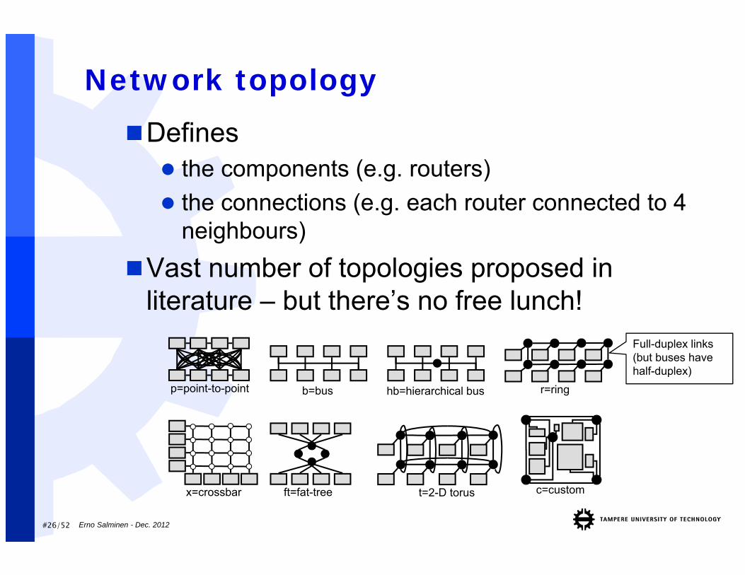
Network topologyDefines the components (e.g. routers) the connections (e.g. each router connected to 4
neighbours)Vast number of topologies proposed in
literature – but there’s no free lunch!
b=bus hb=hierarchical bus
ft=fat-treex=crossbar
r=ring
c=custom
p=point-to-point
t=2-D torus
Full-duplex links (but buses have half-duplex)
Erno Salminen - Dec. 2012
#27/52
Network topology (2)Can be modeled with graphs
node = router (usually includes a processing unit) edge = data stream
Number of nodes denoted with NAverage path length L
Avg num of edges between all nodes in graph Small L desired for small latency
Average degree <k> Avg. num of edges in each switch Large <k> may decrease L but router implementation
gets more complex also 3D topologies look cool on paper but are rather hard
to implement on 2D silicon…
Erno Salminen - Dec. 2012
#28/52
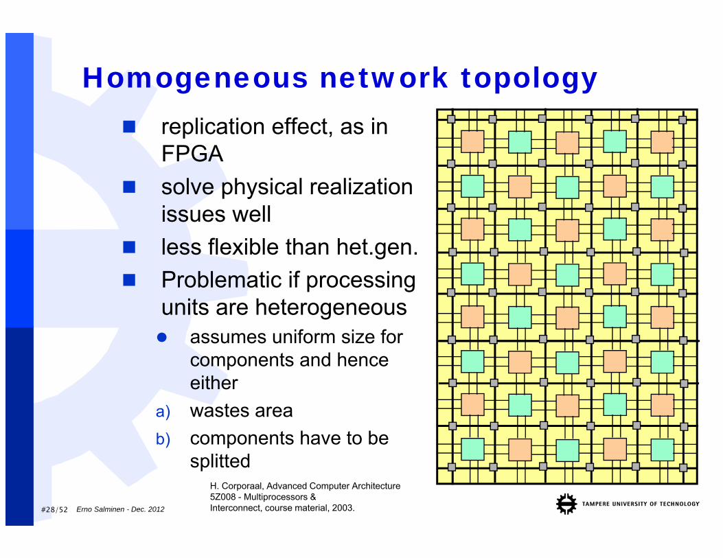
Homogeneous network topology replication effect, as in
FPGA solve physical realization
issues well less flexible than het.gen. Problematic if processing
units are heterogeneous assumes uniform size for
components and hence either
a) wastes area b) components have to be
splittedH. Corporaal, Advanced Computer Architecture5Z008 - Multiprocessors &Interconnect, course material, 2003.Erno Salminen - Dec. 2012
#29/52
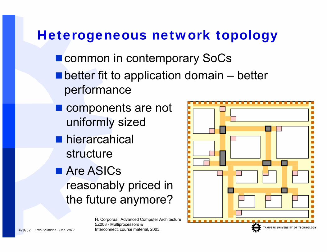
Heterogeneous network topologycommon in contemporary SoCsbetter fit to application domain – better
performance components are not
uniformly sized hierarcahical
structure Are ASICs
reasonably priced in the future anymore?
H. Corporaal, Advanced Computer Architecture5Z008 - Multiprocessors &Interconnect, course material, 2003.Erno Salminen - Dec. 2012
#30/52
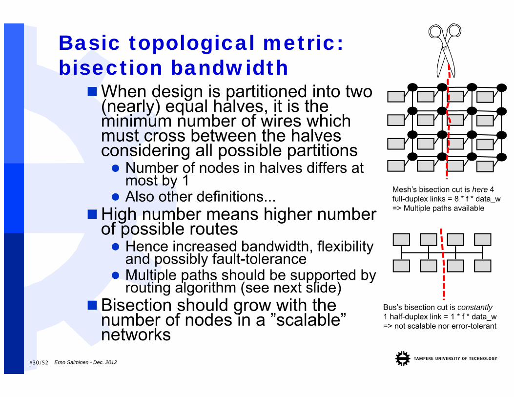
Basic topological metric: bisection bandwidthWhen design is partitioned into two
(nearly) equal halves, it is the minimum number of wires which must cross between the halves considering all possible partitions Number of nodes in halves differs at
most by 1 Also other definitions...
High number means higher numberof possible routes Hence increased bandwidth, flexibility
and possibly fault-tolerance Multiple paths should be supported by
routing algorithm (see next slide)Bisection should grow with the
number of nodes in a ”scalable” networks
Bus’s bisection cut is constantly1 half-duplex link = 1 * f * data_w=> not scalable nor error-tolerant
Mesh’s bisection cut is here 4 full-duplex links = 8 * f * data_w=> Multiple paths available
Erno Salminen - Dec. 2012
#31/52
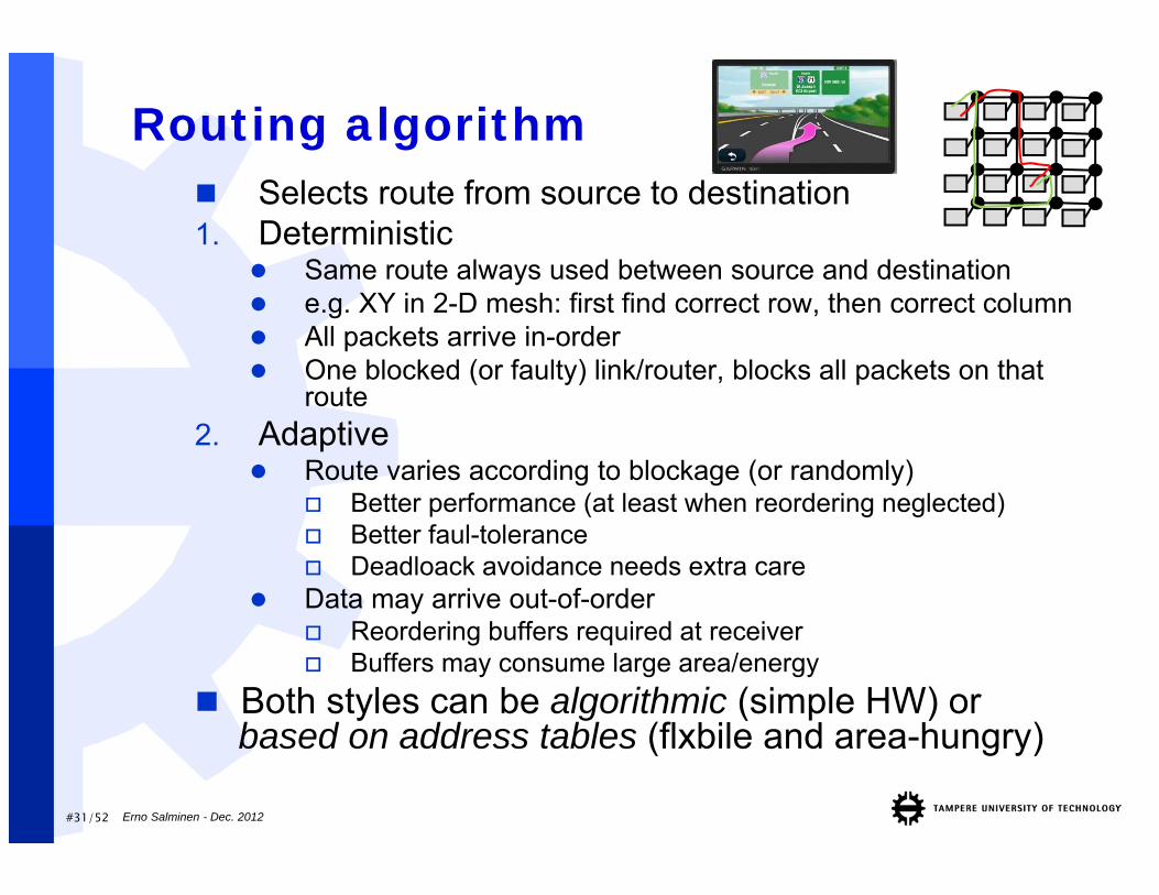
Routing algorithm Selects route from source to destination1. Deterministic
Same route always used between source and destination e.g. XY in 2-D mesh: first find correct row, then correct column All packets arrive in-order One blocked (or faulty) link/router, blocks all packets on that
route2. Adaptive
Route varies according to blockage (or randomly) Better performance (at least when reordering neglected) Better faul-tolerance Deadloack avoidance needs extra care
Data may arrive out-of-order Reordering buffers required at receiver Buffers may consume large area/energy
Both styles can be algorithmic (simple HW) orbased on address tables (flxbile and area-hungry)
Erno Salminen - Dec. 2012
#32/52
SwitchingSelects when data moves forward and how
it is buffered1. Circuit-switching:
A path is formed (reserved) from source to destination before transfers, as in old-time telephones
Guaranteed latency and bandwidth for transfers, no buffering needed
Non-determistic path setup delay2. Store-and-forward (packet) switching
Data forwarded when the router receives a whole packet
Whole packet buffered Increases area and latency Packets contend for the resources and latency varies
in all packet-switched schemes
Erno Salminen - Dec. 2012
#33/52
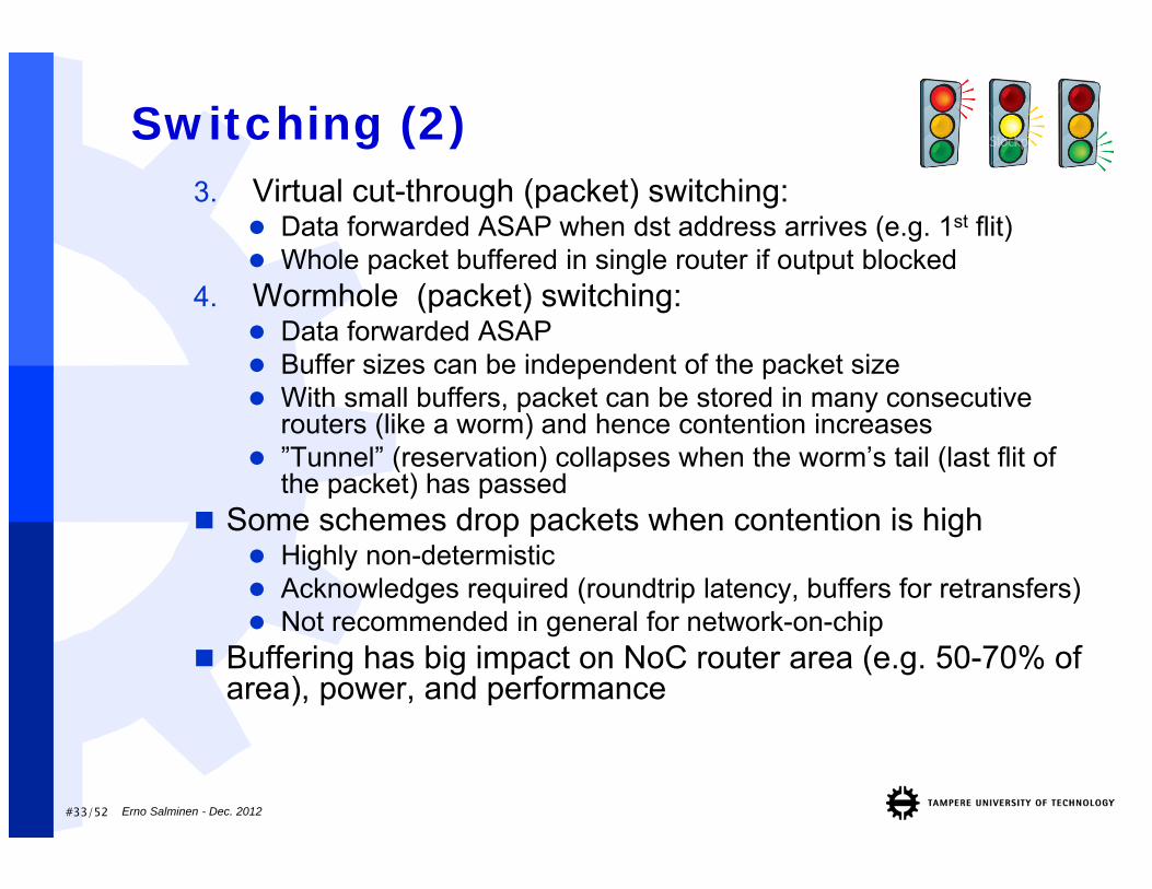
Switching (2)3. Virtual cut-through (packet) switching:
Data forwarded ASAP when dst address arrives (e.g. 1st flit) Whole packet buffered in single router if output blocked
4. Wormhole (packet) switching: Data forwarded ASAP Buffer sizes can be independent of the packet size With small buffers, packet can be stored in many consecutive
routers (like a worm) and hence contention increases ”Tunnel” (reservation) collapses when the worm’s tail (last flit of
the packet) has passed Some schemes drop packets when contention is high
Highly non-determistic Acknowledges required (roundtrip latency, buffers for retransfers) Not recommended in general for network-on-chip
Buffering has big impact on NoC router area (e.g. 50-70% of area), power, and performance
Erno Salminen - Dec. 2012
#34/52
Switching examples
Erno Salminen - Dec. 2012
src
dst
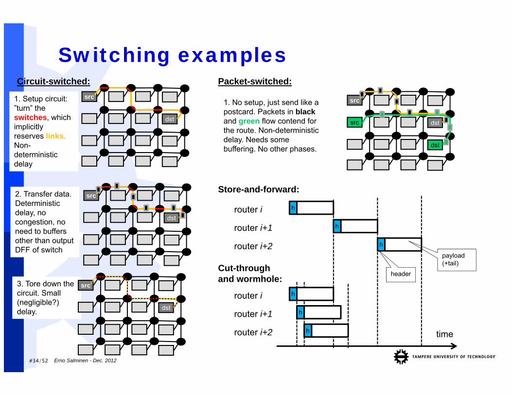
Circuit-switched:
1. Setup circuit: ”turn” the switches, which implicitly reserves links. Non-deterministic delay
2. Transfer data. Deterministic delay, no congestion, no need to buffers other than output DFF of switch
src
dst
3. Tore down the circuit. Small (negligible?) delay.
src
src
dst
dst
1. No setup, just send like a postcard. Packets in blackand green flow contend for the route. Non-deterministic delay. Needs some buffering. No other phases.
Packet-switched:
hrouter i
router i+1
router i+2
h
h
Store-and-forward:
h
h
h
Cut-through and wormhole:
time
router i
router i+1
router i+2
header
payload (+tail)
src
dst
#35/52
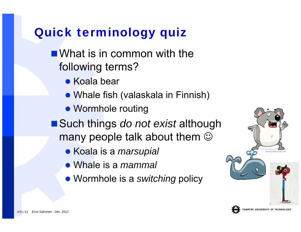
Quick terminology quizWhat is in common with the
following terms? Koala bear Whale fish (valaskala in Finnish) Wormhole routing
Such things do not exist although many people talk about them Koala is a marsupial Whale is a mammal Wormhole is a switching policy
Erno Salminen - Dec. 2012
Example topologies
Erno Salminen - Dec. 2012
#37/52
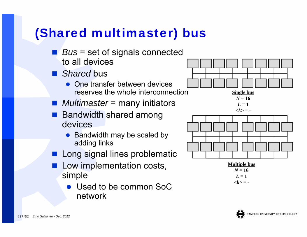
(Shared multimaster) bus Bus = set of signals connected
to all devices Shared bus
One transfer between devices reserves the whole interconnection
Multimaster = many initiators Bandwidth shared among
devices Bandwidth may be scaled by
adding links Long signal lines problematic Low implementation costs,
simple Used to be common SoC
network
Single busN = 16L = 1
<k> = -
Multiple busN = 16L = 1
<k> = -
Erno Salminen - Dec. 2012
#38/52
Bus arbitration / addr decoding Arbitration decides which master can use the
shared resource (e.g. bus or memory) Single-master system does not need arbitration E.g. priority, round-robin, TDMA Two-level : e.g. TDMA + priority May be pipelined with previous transfer
Decoding is needed to determine the target Central / Distributed schemes Address and Data are broadcast to every node Decoder select which read the data or respond
Erno Salminen - Dec. 2012
#39/52
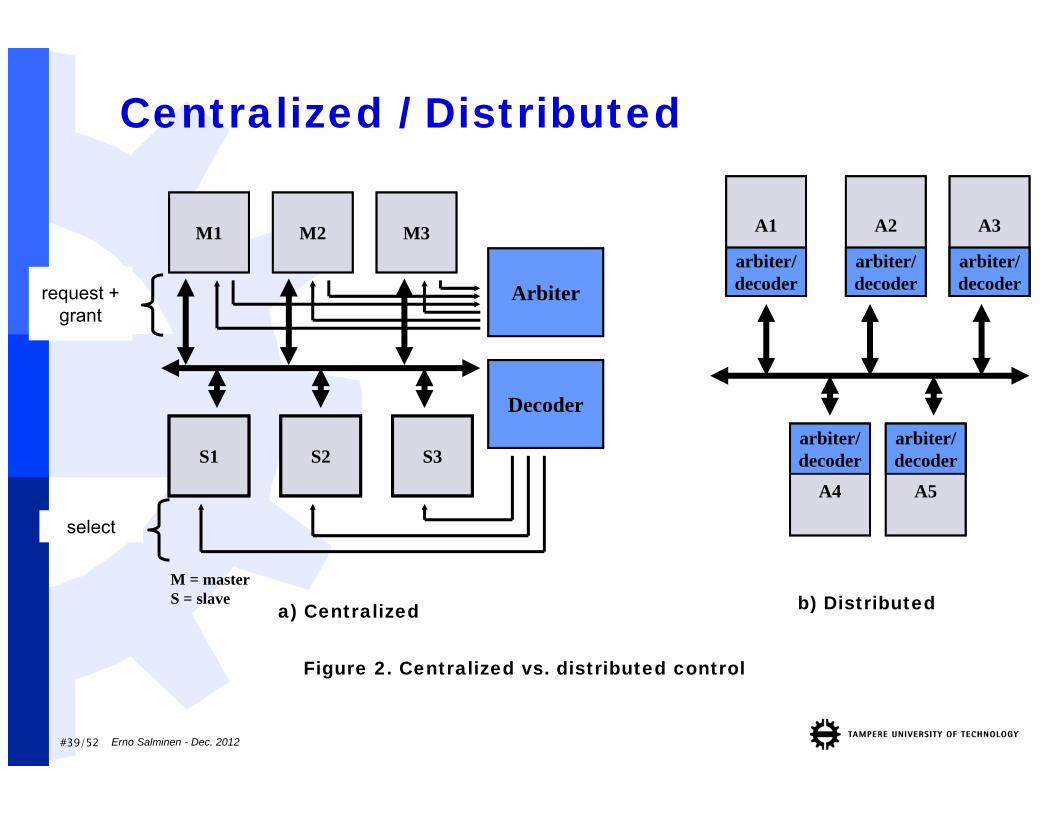
Centralized / Distributed
M = masterS = slave
Arbiter
M1 M2 M3
S1 S2 S3
Decoder
a) Centralized
A2
arbiter/decoder
A3
arbiter/decoder
A1
arbiter/decoder
A4
arbiter/decoder
A5
arbiter/decoder
b) Distributed
Figure 2. Centralized vs. distributed control
request + grant
select
Erno Salminen - Dec. 2012
#40/52
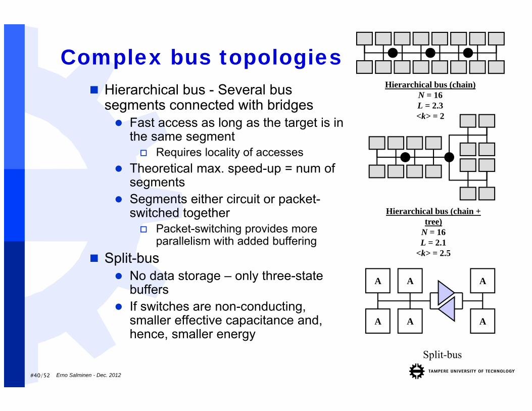
Complex bus topologies Hierarchical bus - Several bus
segments connected with bridges Fast access as long as the target is in
the same segment Requires locality of accesses
Theoretical max. speed-up = num of segments
Segments either circuit or packet-switched together Packet-switching provides more
parallelism with added buffering Split-bus
No data storage – only three-state buffers
If switches are non-conducting, smaller effective capacitance and, hence, smaller energy
Split-bus
A A
A A
A
A
Hierarchical bus (chain + tree)
N = 16L = 2.1
<k> = 2.5
Hierarchical bus (chain)N = 16L = 2.3<k> = 2
Erno Salminen - Dec. 2012
#41/52
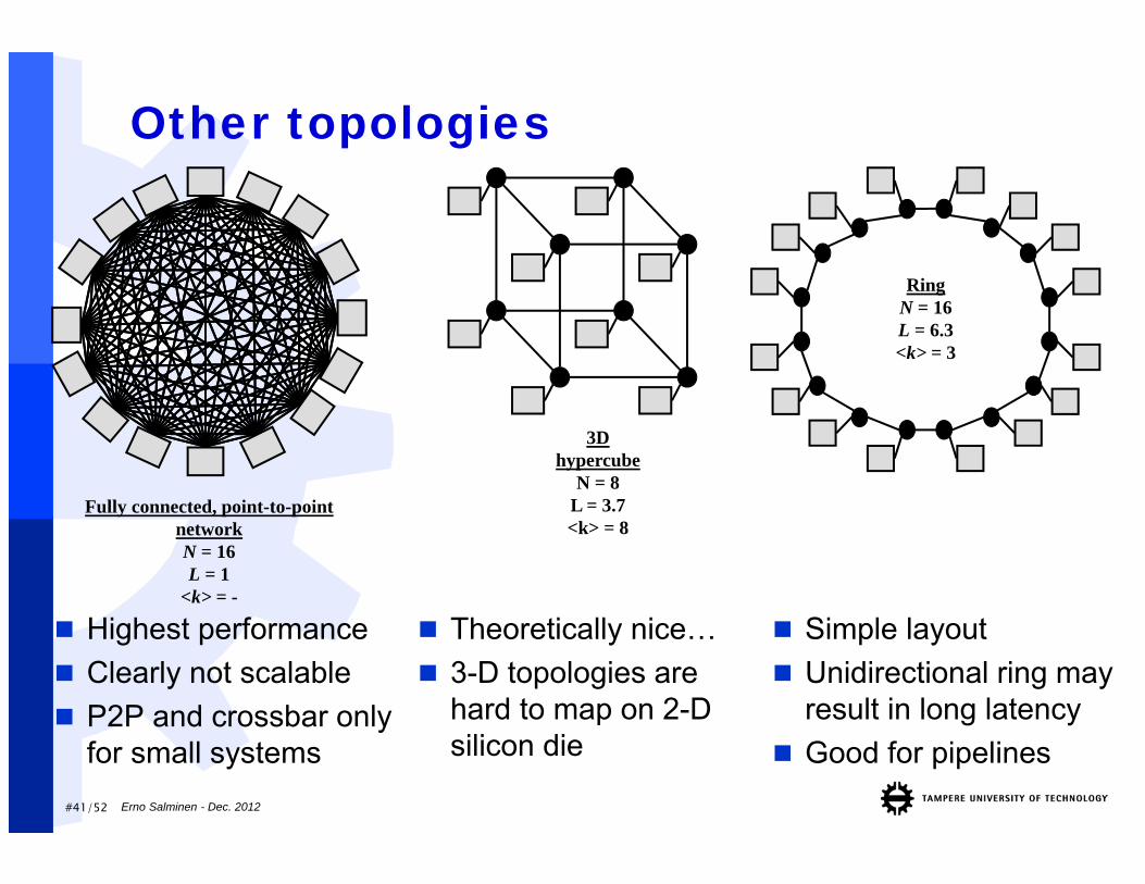
Other topologies
RingN = 16L = 6.3<k> = 3
Fully connected, point-to-point networkN = 16L = 1
<k> = -
3D hypercube
N = 8L = 3.7<k> = 8
Highest performance Clearly not scalable P2P and crossbar only
for small systems
Theoretically nice… 3-D topologies are
hard to map on 2-D silicon die
Simple layout Unidirectional ring may
result in long latency Good for pipelines
Erno Salminen - Dec. 2012
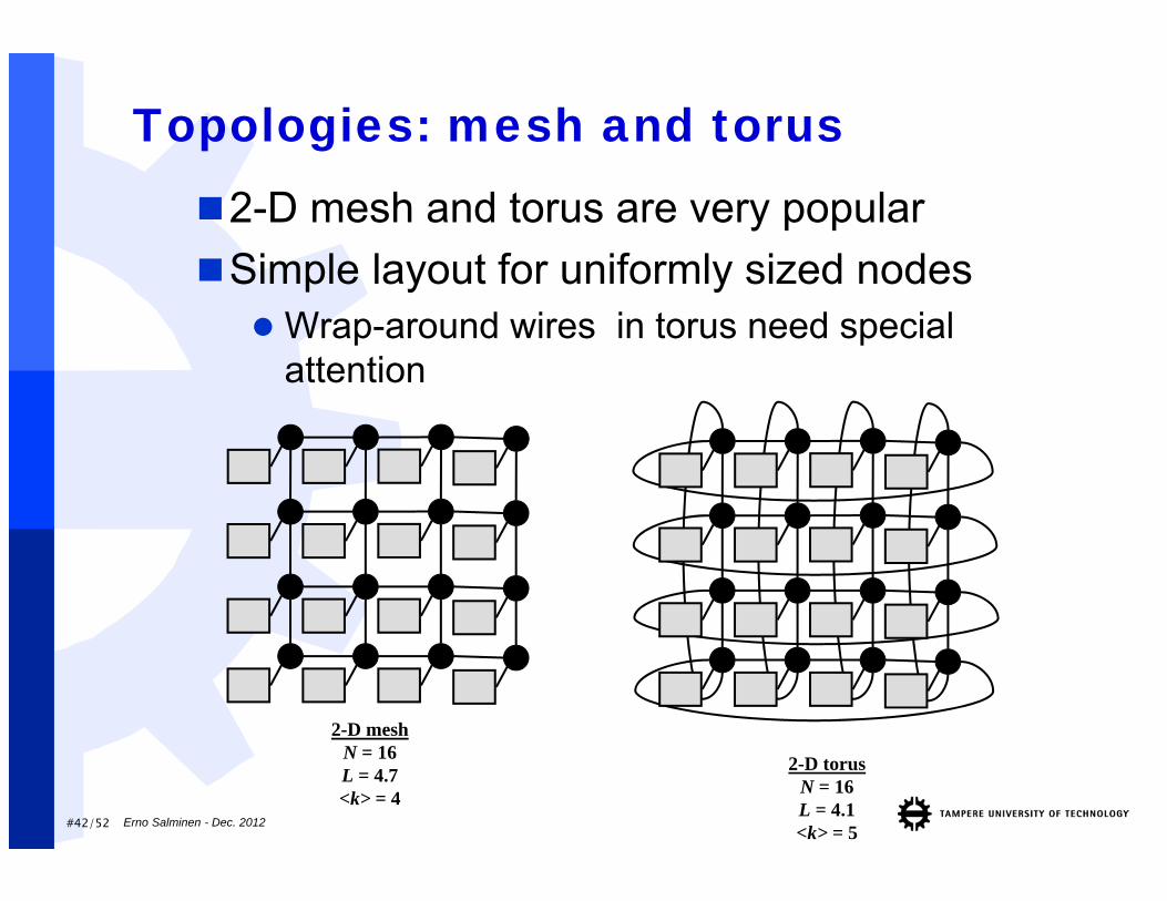
#42/52
Topologies: mesh and torus2-D mesh and torus are very popularSimple layout for uniformly sized nodes Wrap-around wires in torus need special
attention
2-D meshN = 16L = 4.7<k> = 4
2-D torusN = 16L = 4.1<k> = 5
Erno Salminen - Dec. 2012
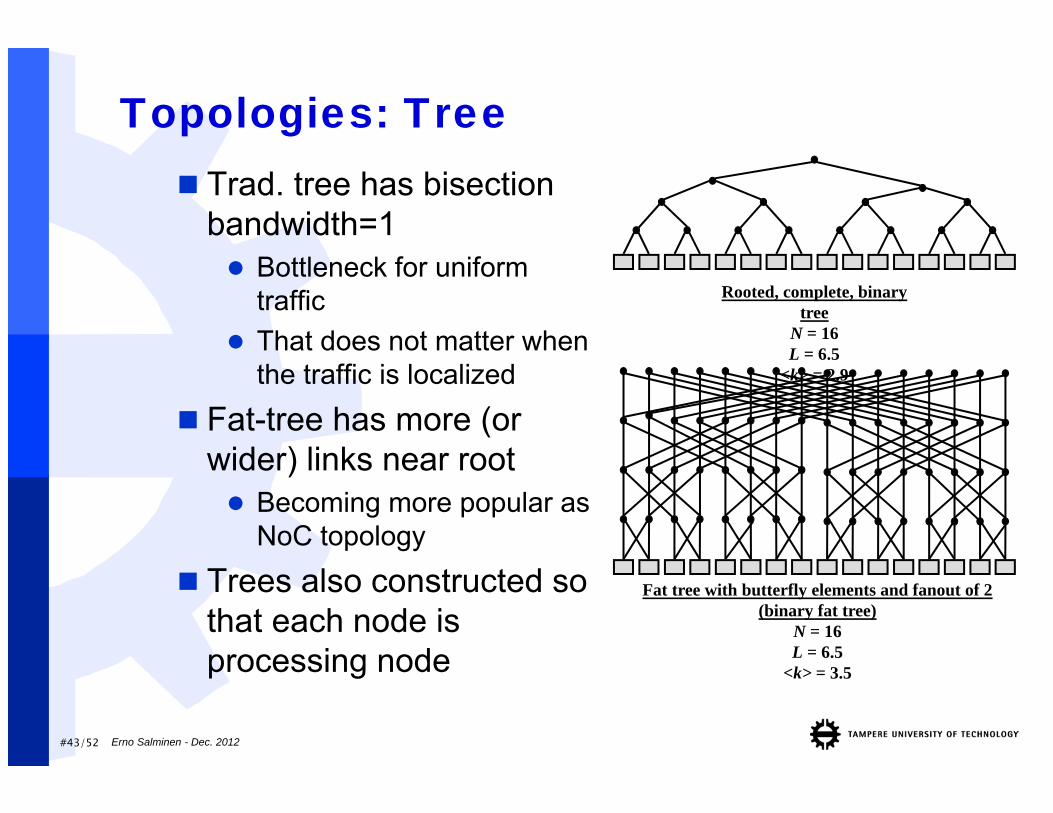
#43/52
Topologies: Tree Trad. tree has bisection
bandwidth=1 Bottleneck for uniform
traffic That does not matter when
the traffic is localized
Fat-tree has more (or wider) links near root Becoming more popular as
NoC topology
Trees also constructed so that each node is processing node
Rooted, complete, binary tree
N = 16L = 6.5
<k> = 2.9
Fat tree with butterfly elements and fanout of 2 (binary fat tree)
N = 16L = 6.5
<k> = 3.5
Erno Salminen - Dec. 2012
#44/52
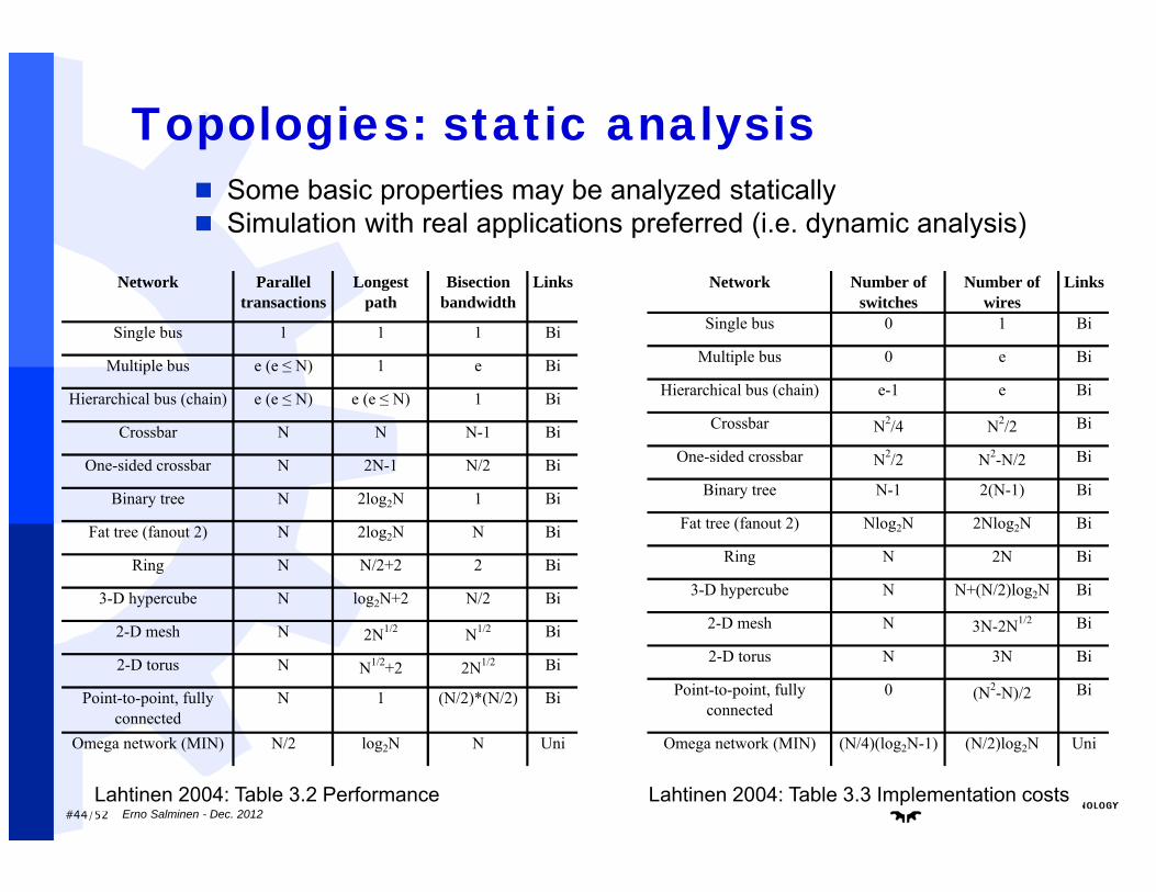
Topologies: static analysis Some basic properties may be analyzed statically Simulation with real applications preferred (i.e. dynamic analysis)
Network Number of switches
Number of wires
Links
Single bus 0 1 Bi
Multiple bus 0 e Bi
Hierarchical bus (chain) e-1 e Bi
Crossbar N2/4 N2/2 Bi
One-sided crossbar N2/2 N2-N/2 Bi
Binary tree N-1 2(N-1) Bi
Fat tree (fanout 2) Nlog2N 2Nlog2N Bi
Ring N 2N Bi
3-D hypercube N N+(N/2)log2N Bi
2-D mesh N 3N-2N1/2 Bi
2-D torus N 3N Bi
Point-to-point, fully connected
0 (N2-N)/2 Bi
Omega network (MIN) (N/4)(log2N-1) (N/2)log2N Uni
Network Parallel transactions
Longest path
Bisection bandwidth
Links
Single bus 1 1 1 Bi
Multiple bus e (e ≤ N) 1 e Bi
Hierarchical bus (chain) e (e ≤ N) e (e ≤ N) 1 Bi
Crossbar N N N-1 Bi
One-sided crossbar N 2N-1 N/2 Bi
Binary tree N 2log2N 1 Bi
Fat tree (fanout 2) N 2log2N N Bi
Ring N N/2+2 2 Bi
3-D hypercube N log2N+2 N/2 Bi
2-D mesh N 2N1/2 N1/2 Bi
2-D torus N N1/2+2 2N1/2 Bi
Point-to-point, fully connected
N 1 (N/2)*(N/2) Bi
Omega network (MIN) N/2 log2N N Uni
Lahtinen 2004: Table 3.2 Performance Lahtinen 2004: Table 3.3 Implementation costsErno Salminen - Dec. 2012
#45/52
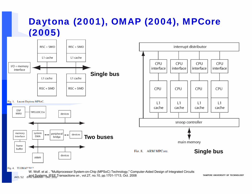
Daytona (2001), OMAP (2004), MPCore(2005)
W. Wolf. et al. , "Multiprocessor System-on-Chip (MPSoC) Technology," Computer-Aided Design of Integrated Circuits and Systems, IEEE Transactions on , vol.27, no.10, pp.1701-1713, Oct. 2008
Single bus
Two buses
Single bus
Erno Salminen - Dec. 2012
#46/52
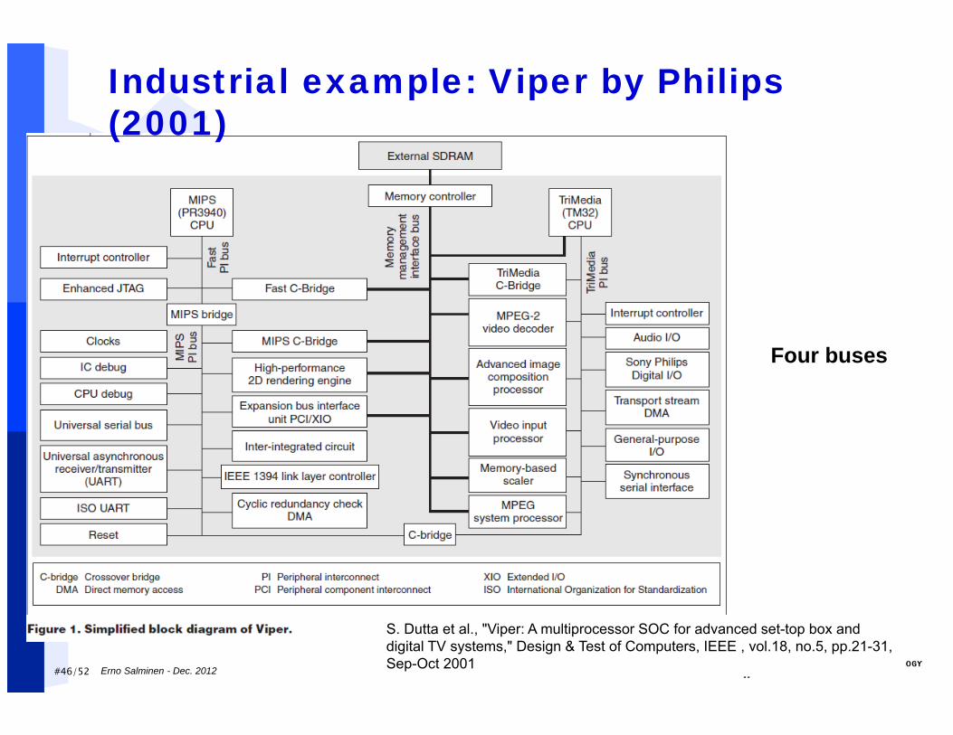
S. Dutta et al., "Viper: A multiprocessor SOC for advanced set-top box and digital TV systems," Design & Test of Computers, IEEE , vol.18, no.5, pp.21-31, Sep-Oct 2001
Industrial example: Viper by Philips (2001)
Four buses
Erno Salminen - Dec. 2012
#47/52
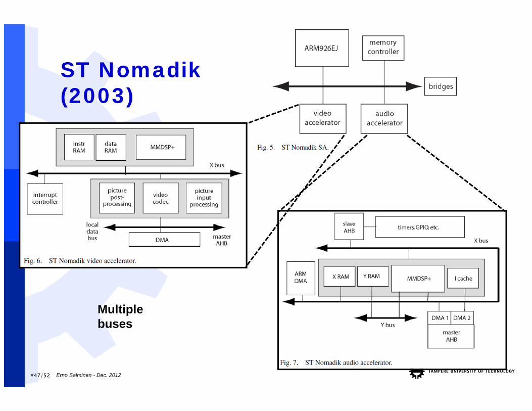
ST Nomadik(2003)
Erno Salminen - Dec. 2012
Multiple buses
#48/52
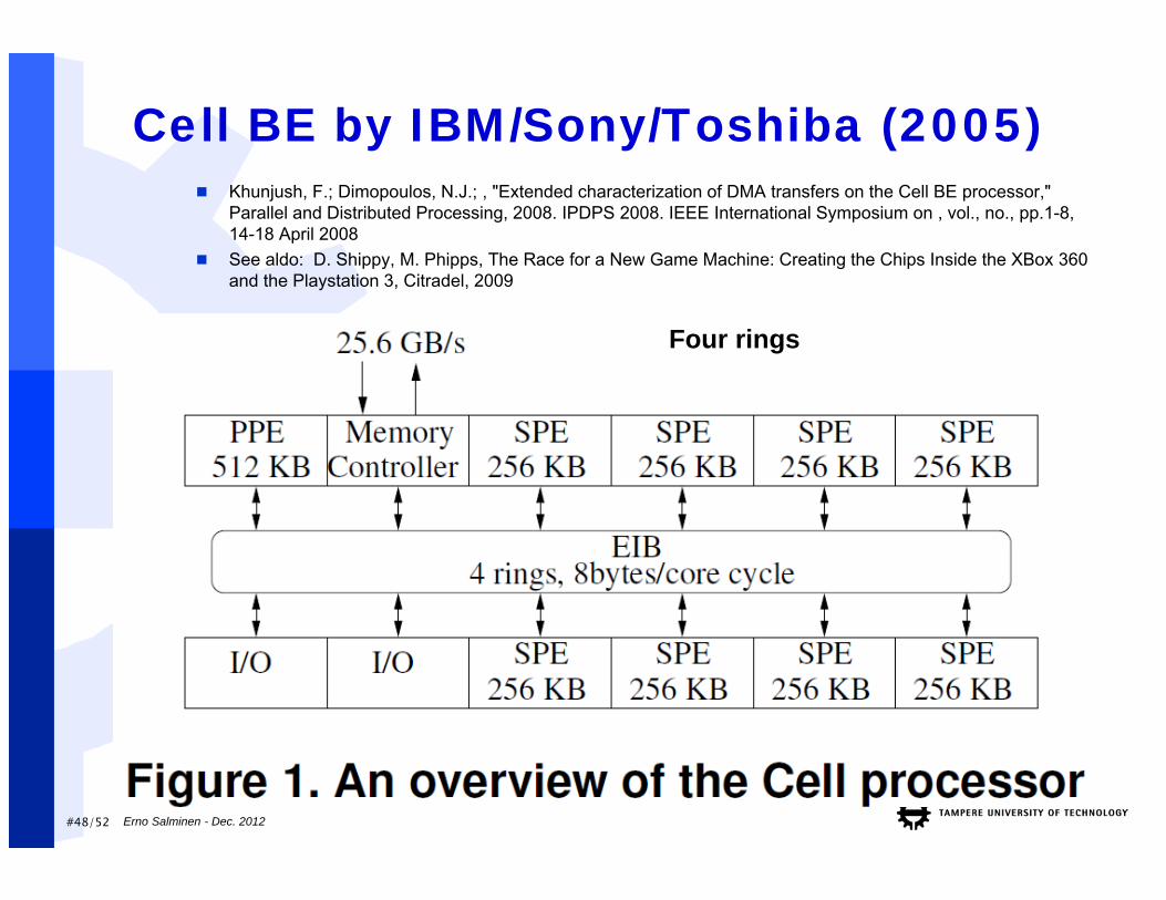
Cell BE by IBM/Sony/Toshiba (2005)
Erno Salminen - Dec. 2012
Khunjush, F.; Dimopoulos, N.J.; , "Extended characterization of DMA transfers on the Cell BE processor," Parallel and Distributed Processing, 2008. IPDPS 2008. IEEE International Symposium on , vol., no., pp.1-8, 14-18 April 2008
See aldo: D. Shippy, M. Phipps, The Race for a New Game Machine: Creating the Chips Inside the XBox 360 and the Playstation 3, Citradel, 2009
Four rings
#49/52
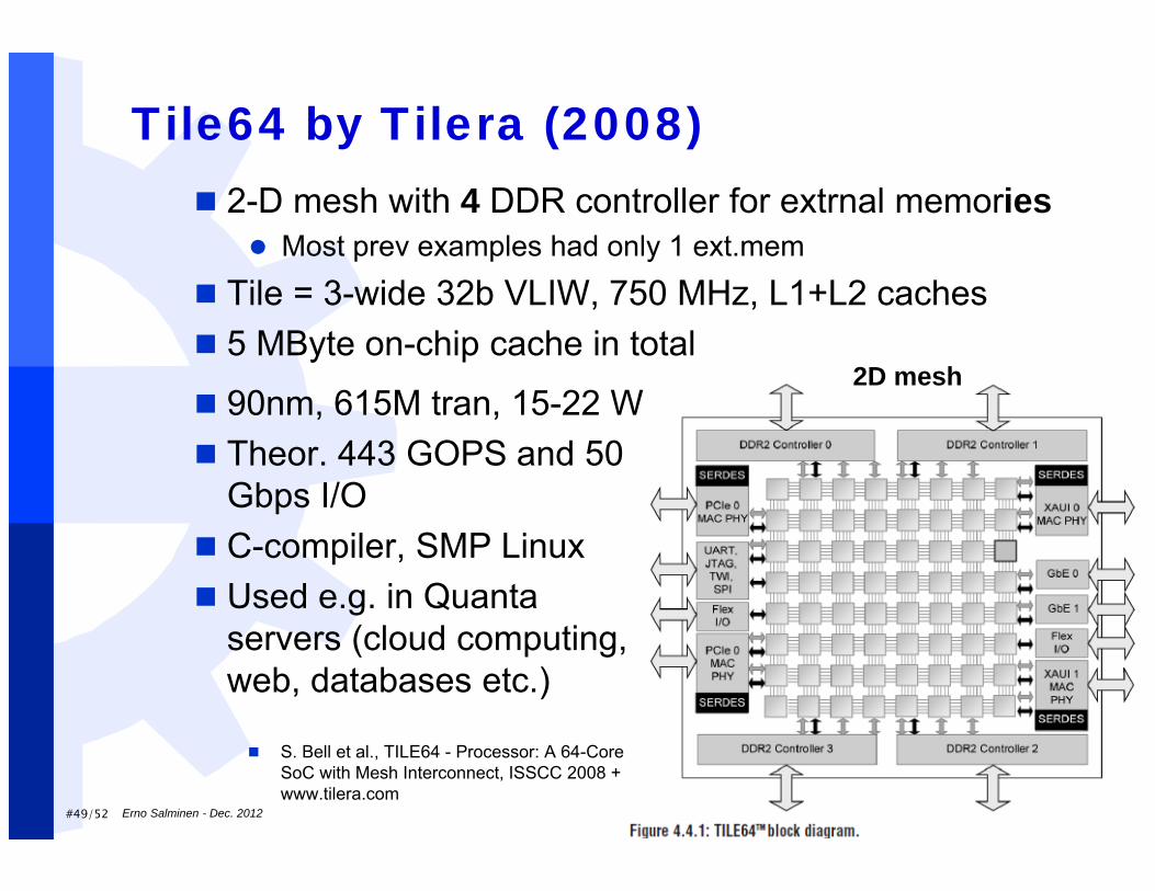
Tile64 by Tilera (2008)
Erno Salminen - Dec. 2012
S. Bell et al., TILE64 - Processor: A 64-Core SoC with Mesh Interconnect, ISSCC 2008 + www.tilera.com
2-D mesh with 4 DDR controller for extrnal memories Most prev examples had only 1 ext.mem
Tile = 3-wide 32b VLIW, 750 MHz, L1+L2 caches 5 MByte on-chip cache in total
90nm, 615M tran, 15-22 W Theor. 443 GOPS and 50
Gbps I/O C-compiler, SMP Linux Used e.g. in Quanta
servers (cloud computing, web, databases etc.)
2D mesh
#50/52
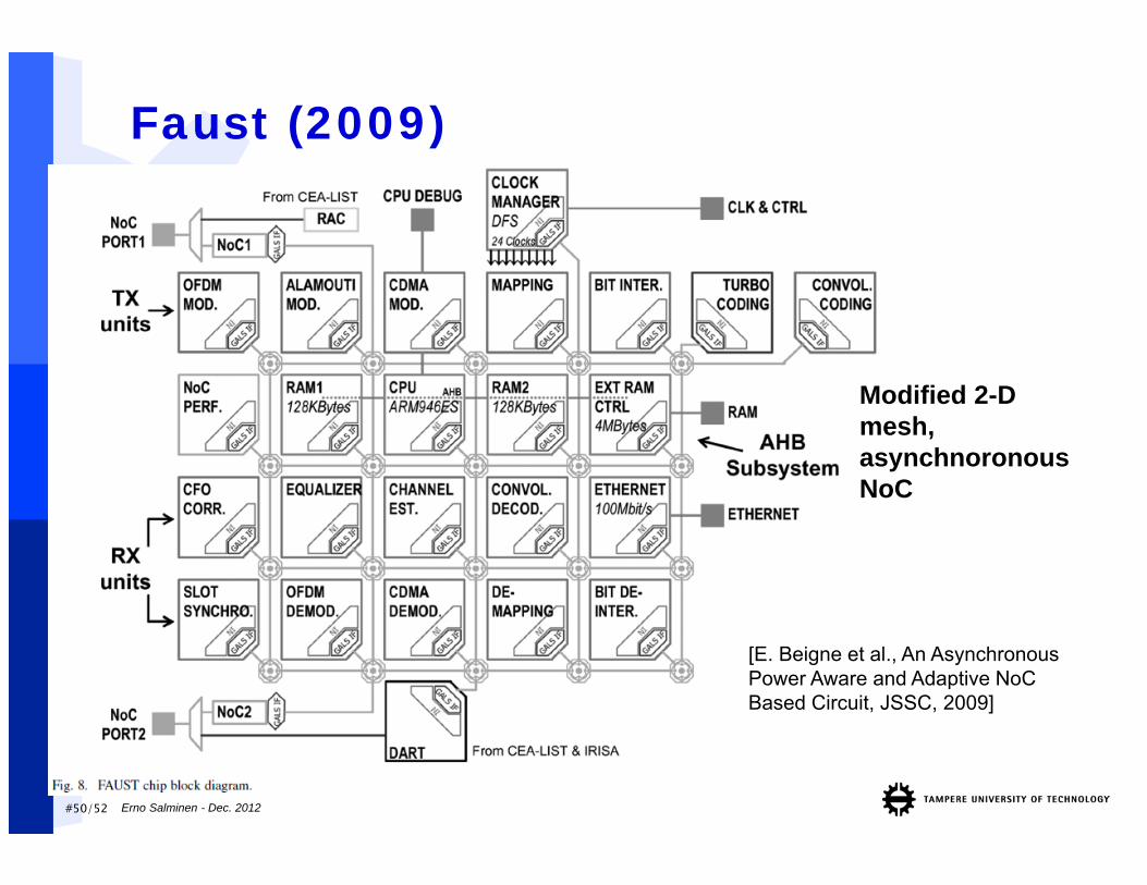
Faust (2009)
Erno Salminen - Dec. 2012
Modified 2-D mesh, asynchnoronous NoC
[E. Beigne et al., An Asynchronous Power Aware and Adaptive NoC Based Circuit, JSSC, 2009]
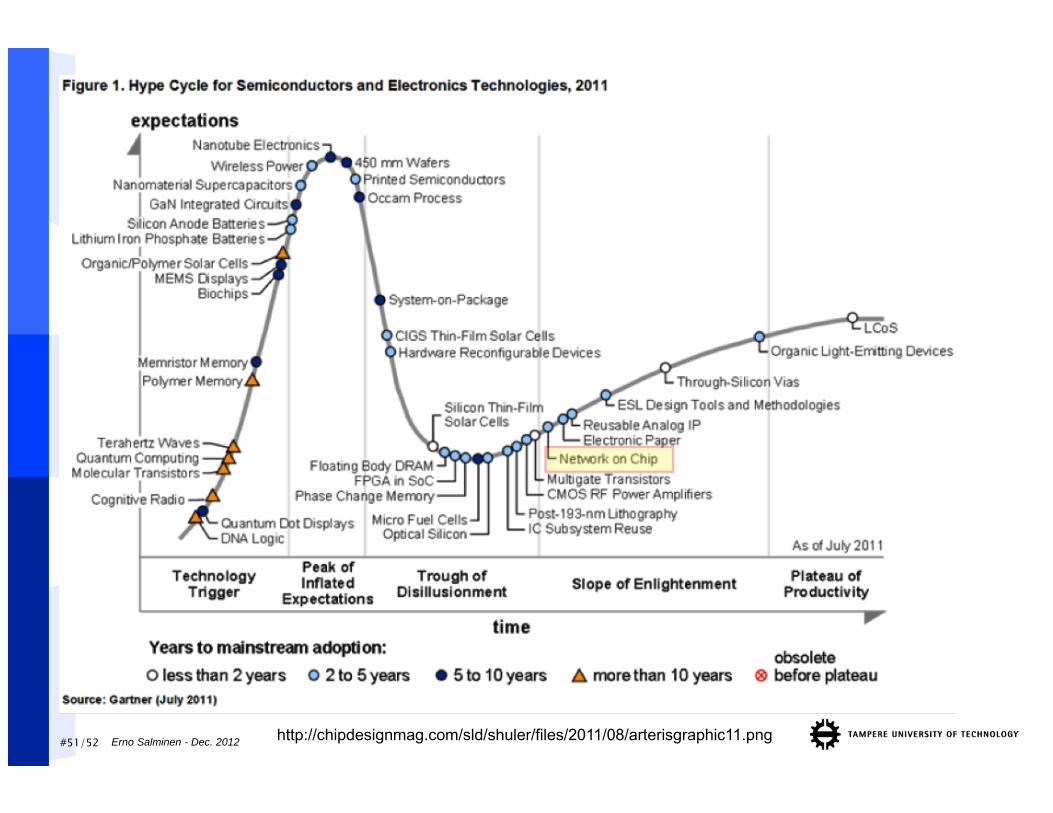
#51/52 Erno Salminen - Dec. 2012 http://chipdesignmag.com/sld/shuler/files/2011/08/arterisgraphic11.png
#52/52 Erno Salminen - Dec. 2012
ConclusionSoC has many components, different
requirementsWire delays and power consumption
becoming very problematicBig difference between local and global (or
off-chip) communicationFully synchronous approach becoming
unfeasibleNetwork-on-chip = multi-hop on-chip network Often packet-switched Buffering, routing, and topology are important
design decisions

Erno Salminen - Dec. 2012
NoC SurveyNote: All slides in this set are exam material!
#54/52 Erno Salminen - Dec. 2012
Survey of Network-on-chip proposals [Salminen et al. 2008]
This paper gives an overview of state-of-the-art regarding the network-on-chip (NoC) proposals.
NoC paradigm replaces dedicated, design-specific wires with scalable, general purpose, multi-hop network. Numerous examples from literature are selected to highlight the contemporary approaches and reported implementation results. The major trends of NoC research and aspects that require more investigations are pointed out.
A packet-switched 2-D mesh is the most used and studied topology so far. It is also a sort of an average NoC currently. Good results and interesting proposals are plenty.
However, large differences in implementation results, vague documentation, and lack of comparison were also observed.
http://www.ocpip.org/uploads/documents/OCP-IP_Survey_of_NoC_Proposals_White_Paper_April_2008.pdf
#55/52 Erno Salminen - Dec. 2012
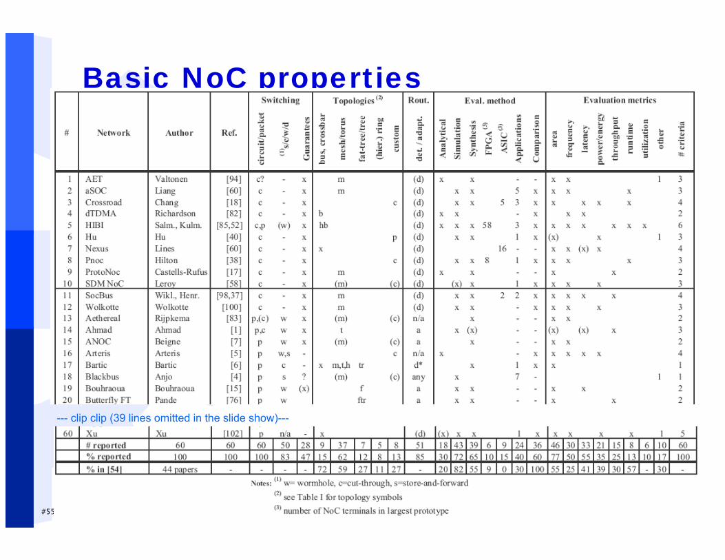
Basic NoC properties
--- clip clip (39 lines omitted in the slide show)---
#56/52 Erno Salminen - Dec. 2012
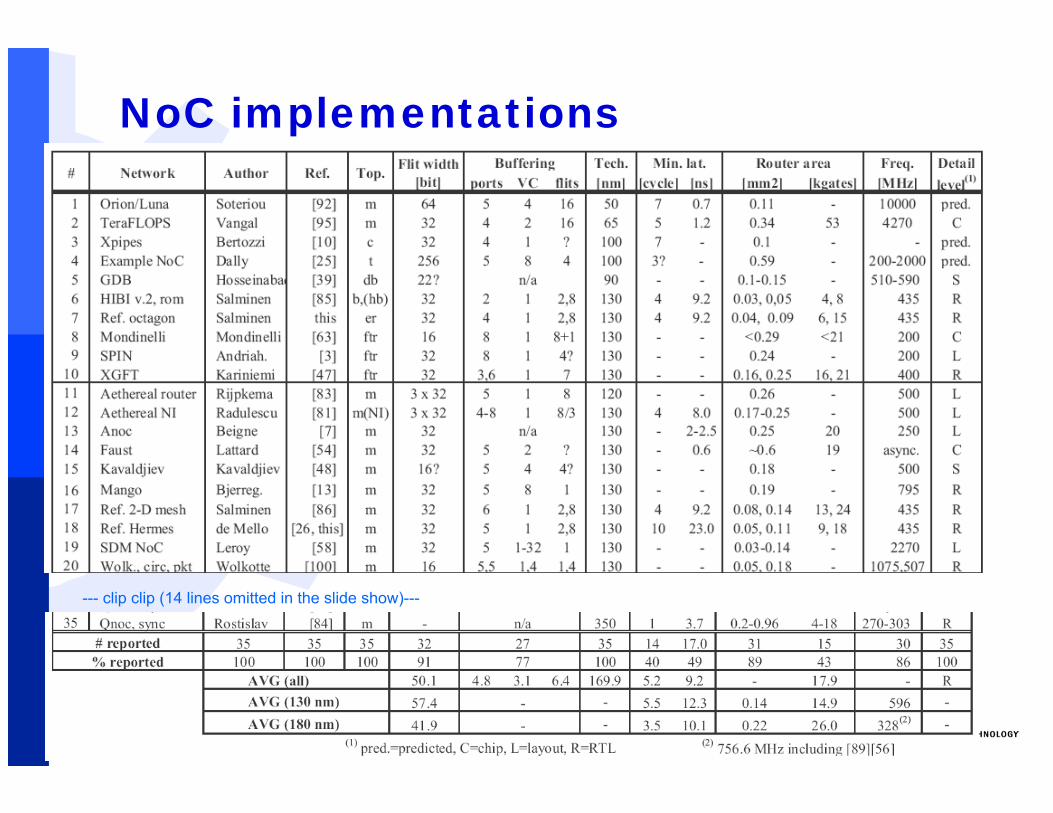
NoC implementations
--- clip clip (14 lines omitted in the slide show)---
#57/52 Erno Salminen - Dec. 2012
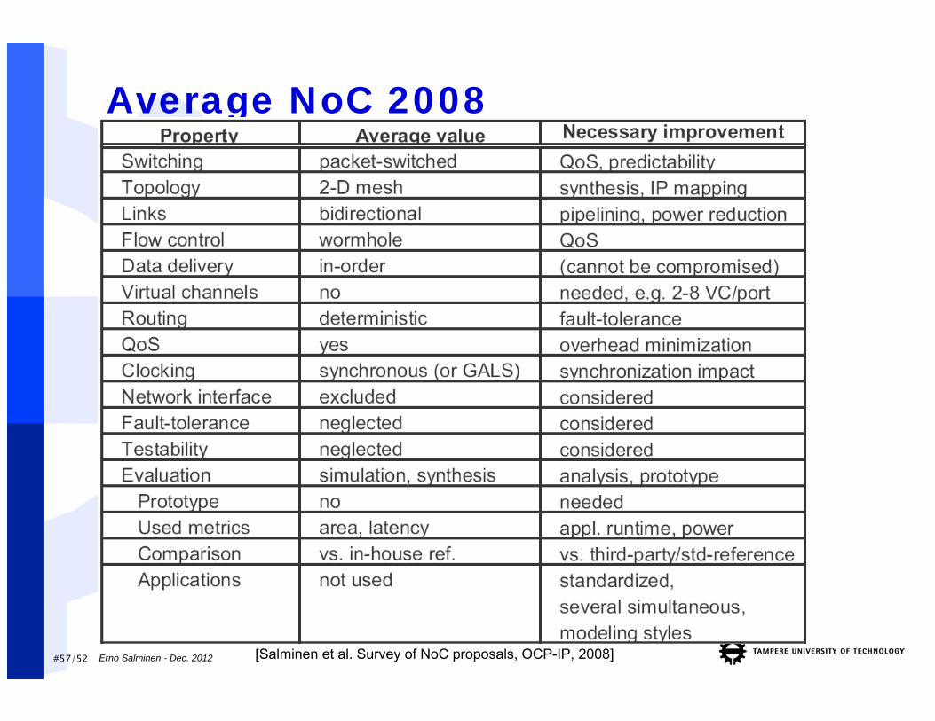
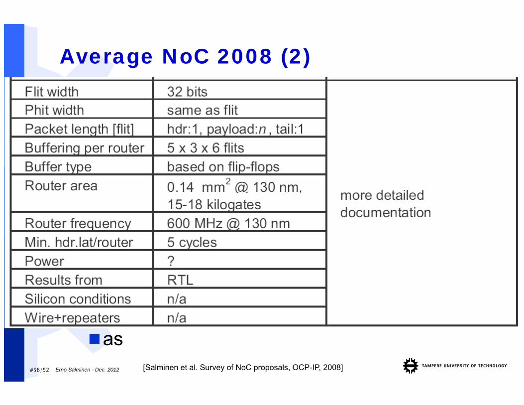
Average NoC 2008
[Salminen et al. Survey of NoC proposals, OCP-IP, 2008]
#58/52 Erno Salminen - Dec. 2012
Average NoC 2008 (2)
as[Salminen et al. Survey of NoC proposals, OCP-IP, 2008]
Erno Salminen - Dec. 2012
Case Study
Managing Interconnection Complexity in Heterogeneous IP Block Interconnection(HIBI)
#60/52 Erno Salminen - Dec. 2012
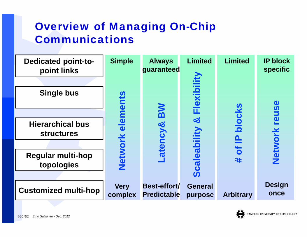
Overview of Managing On-Chip Communications
Dedicated point-to-point links
Single bus
Regular multi-hop topologies
Simple Alwaysguaranteed
Customized multi-hop
LimitedLimited
Verycomplex
Designonce
Generalpurpose
Best-effort/Predictable
IP block specific
Net
wor
k el
emen
ts
Late
ncy&
BW
Scal
eabi
lity
& F
lexi
bilit
y
# of
IP b
lock
s
Net
wor
k re
use
Arbitrary
Hierarchical bus structures
#61/52 Erno Salminen - Dec. 2012
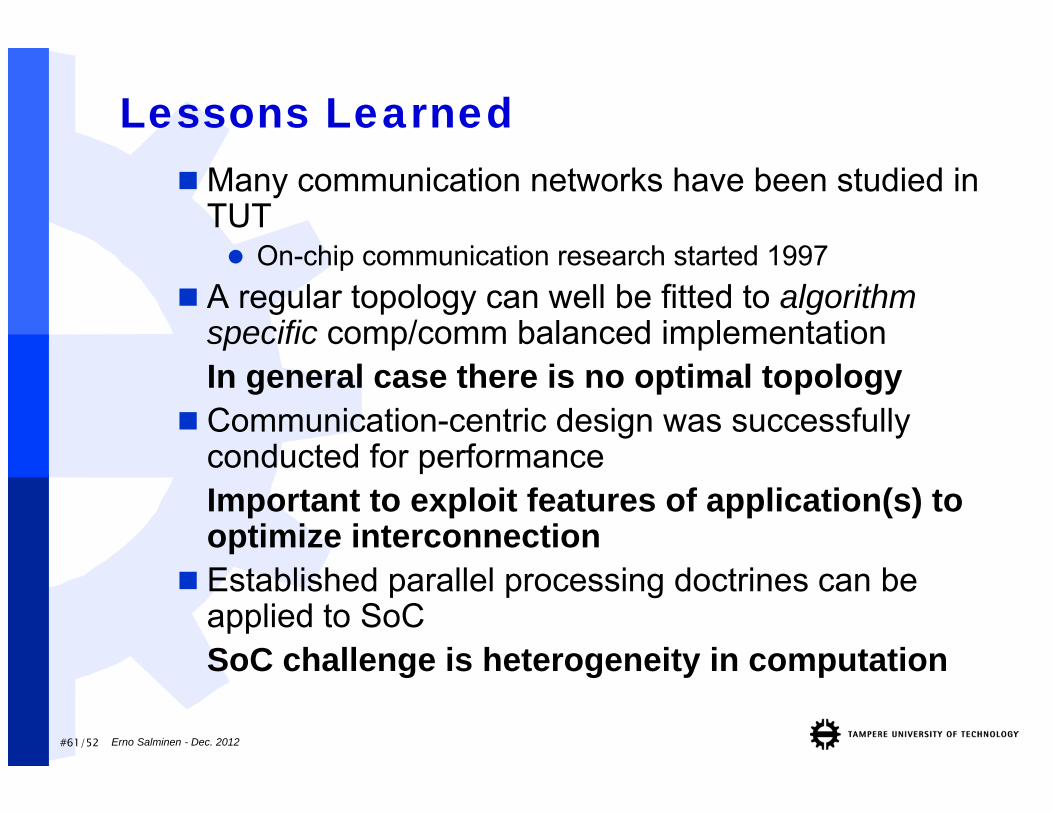
Lessons LearnedMany communication networks have been studied in
TUT On-chip communication research started 1997
A regular topology can well be fitted to algorithm specific comp/comm balanced implementationIn general case there is no optimal topology
Communication-centric design was successfully conducted for performanceImportant to exploit features of application(s) to optimize interconnection
Established parallel processing doctrines can be applied to SoCSoC challenge is heterogeneity in computation
#62/52 Erno Salminen - Dec. 2012
Interconnection Implementation View Make lowest level data transfer mechanisms simple and
efficient Minimum number of signals “Every clock edge carries useful data in transaction”
Perform all high-level operations on basic mechanisms Layered protocol model, OCP compatible Message passing
Use identical HW modules to compose overall interconnection Translate IP specific communication operations to network Support all (practical) topologies No limits to number of IP blocks (whole design) Support (re-)configurability Fit to all communication needs –from memories to peripherals
“Gives body to build interconnect”
#63/52 Erno Salminen - Dec. 2012
System Design View Make interconnection aware of application functionality
A) System design time Communication profiled from application processes Clustering: localization of communication Allocation of communication resources (segments, buffers) Optimization of non-reconfigurable parameters Initial QoS and other transfer parameters
B) Run time Utilize knowledge of predictable communication events if
available Guaranteed QoS in transfers
Track communication –change QoS & other parameters if required
Totally change mode of operation if required HIBI Design Flow is 80% of the HIBI interconnect scheme
“Gives brains to the communication”
#64/52 Erno Salminen - Dec. 2012
HIBI Identical Interconnection Modules
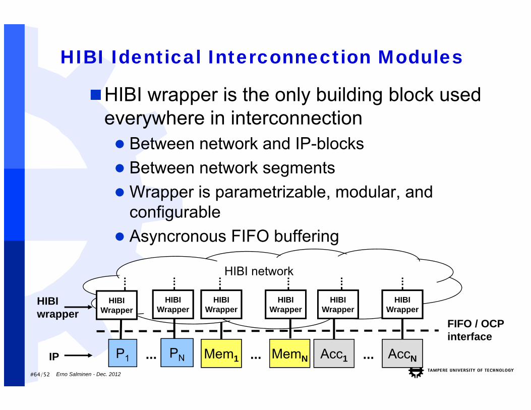
HIBI wrapper is the only building block used everywhere in interconnection Between network and IP-blocks Between network segments Wrapper is parametrizable, modular, and
configurable Asyncronous FIFO buffering
P1 Mem1PN Acc1... AccN...... MemN
FIFO / OCP interface
IP
HIBIwrapper
HIBI network
HIBIWrapper
HIBIWrapper
HIBIWrapper
HIBIWrapper
HIBIWrapper
HIBIWrapper
#65/52 Erno Salminen - Dec. 2012
HIBI Network HIBI network consists of bus segments and bridges
Transfers in segment synchronous circuit switched Transfers across bridges asynchronous packet switched Scales from serial point-to-point link to an arbitrary
topology
Identical signals between wrappers in network side No dedicated point-to-point signals
All signals shared within network segment Wrapper layout is independent of the number of agents
Totally distributed arbitration No central arbiter Each wrapper is aware of communication details
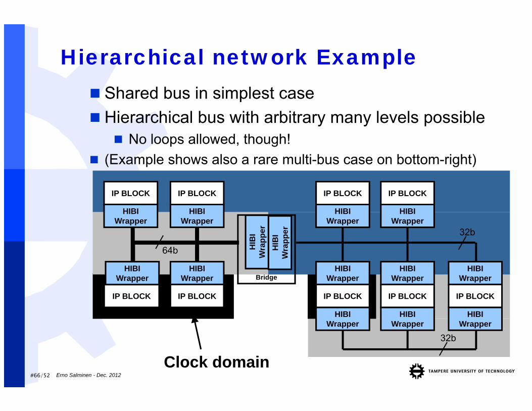
#66/52 Erno Salminen - Dec. 2012
Clock domain
Hierarchical network Example
Bridge
HIB
IW
rapp
erH
IBI
Wra
pper
IP BLOCK
HIBIWrapper
HIBIWrapper
HIBIWrapper
HIBIWrapper
IP BLOCK
HIBIWrapper
IP BLOCK
HIBIWrapper
IP BLOCK
HIBIWrapper
IP BLOCK
HIBIWrapper
IP BLOCK
HIBIWrapper
HIBIWrapper
IP BLOCK
HIBIWrapper
IP BLOCKIP BLOCK
HIBIWrapper
32b
32b
64b
Shared bus in simplest case Hierarchical bus with arbitrary many levels possible
No loops allowed, though! (Example shows also a rare multi-bus case on bottom-right)
#67/52 Erno Salminen - Dec. 2012
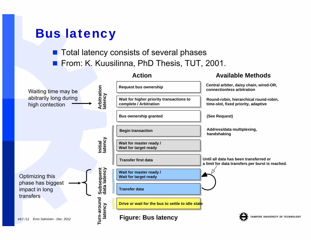
Bus latency Total latency consists of several phases From: K. Kuusilinna, PhD Thesis, TUT, 2001.
Action
Until all data has been transferred ora limit for data transfers per burst is reached.
Transfer data
Wait for master ready /Wait for target ready
Subs
eque
ntda
ta la
tenc
y
Available MethodsRequest bus ownership
Bus ownership granted
Wait for higher priority transactions to complete / Arbitration
Arb
itrat
ion
late
ncy
Central arbiter, daisy chain, wired-OR,connectionless arbitration
Round-robin, hierarchical round-robin,time-slot, fixed priority, adaptive
(See Request)
Begin transaction
Wait for master ready /Wait for target ready
Transfer first data
Initi
alla
tenc
y
Address/data multiplexing,handshaking
Waiting time may be abitrarily long during high contection
Drive or wait for the bus to settle to idle state
Turn
-aro
und
late
ncy
Figure: Bus latency
Optimizing this phase has biggest impact in long transfers
#68/52 Erno Salminen - Dec. 2012
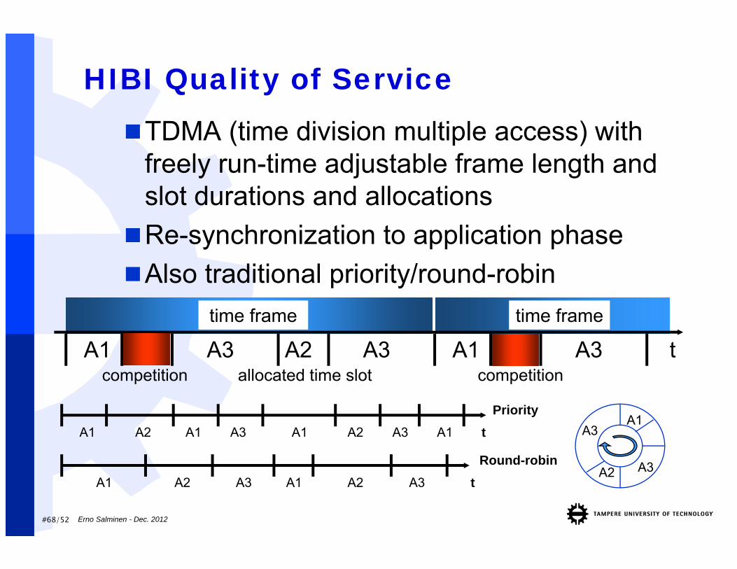
HIBI Quality of ServiceTDMA (time division multiple access) with
freely run-time adjustable frame length and slot durations and allocationsRe-synchronization to application phaseAlso traditional priority/round-robin
A3A2
A3A1
allocated time slotA1
competitionA3 A2 A3 A1 A3time frame
t
A1 A2 A1 A3 A1
A1 A2 A3
Priority
Round-robinA1 A2 A3 t
tA2 A3 A1
time frame
competition
#69/52 Erno Salminen - Dec. 2012
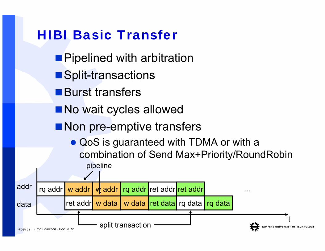
HIBI Basic TransferPipelined with arbitrationSplit-transactionsBurst transfersNo wait cycles allowedNon pre-emptive transfers QoS is guaranteed with TDMA or with a
combination of Send Max+Priority/RoundRobin
t
rq addr
ret addr
addr
data
w addr
w data ret dataw data
w addr rq addr ret addr
rq data rq data
ret addr ...
pipeline
split transaction
#70/52 Erno Salminen - Dec. 2012
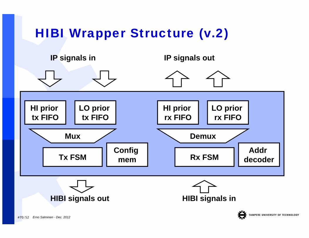
HIBI Wrapper Structure (v.2)
Config mem
HIBI signals out HIBI signals in
IP signals in IP signals out
Tx FSM
HI prior tx FIFO
LO prior tx FIFO
HI prior rx FIFO
LO prior rx FIFO
Mux Demux
Addr decoderRx FSM
#71/52 Erno Salminen - Dec. 2012
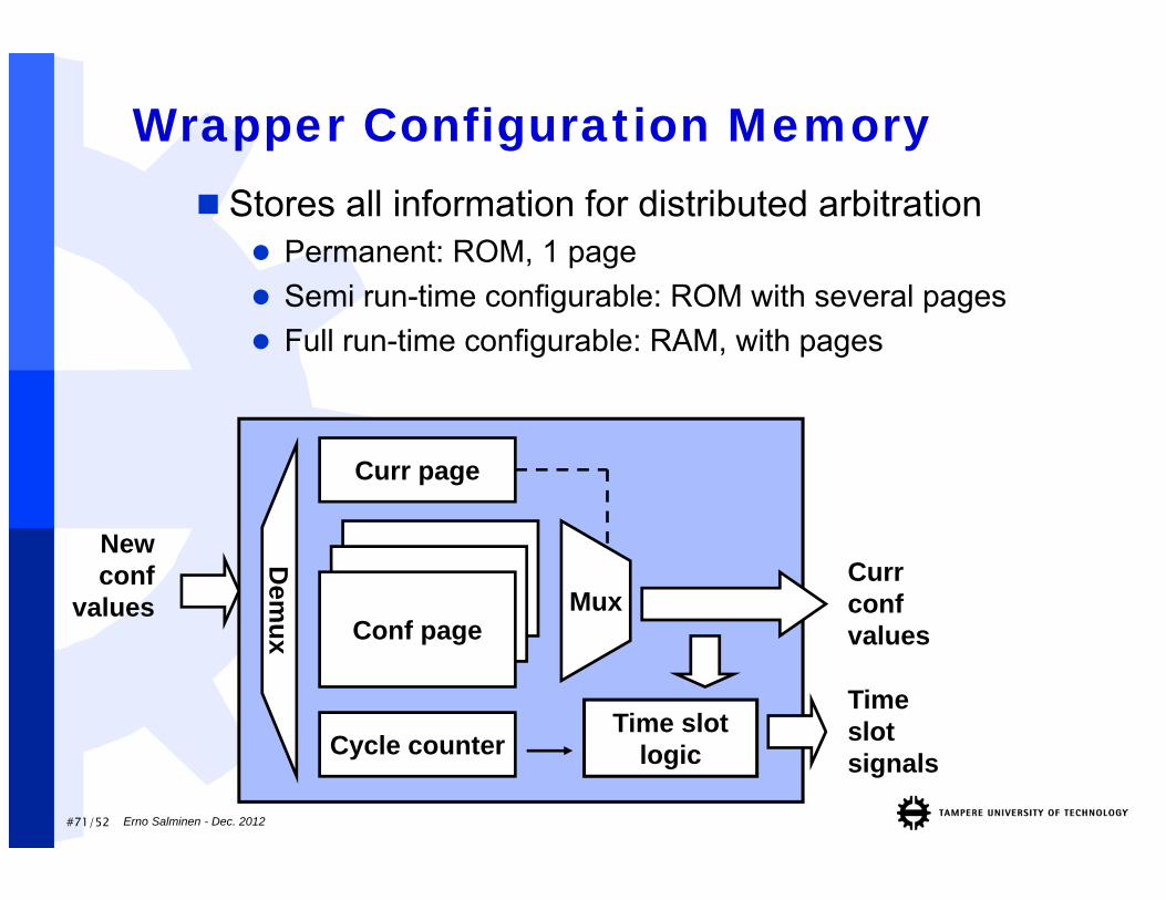
Wrapper Configuration Memory Stores all information for distributed arbitration
Permanent: ROM, 1 page Semi run-time configurable: ROM with several pages Full run-time configurable: RAM, with pages
Time slotlogic
Curr confvalues
Curr page
Conf page
Timeslotsignals
Newconf
values
Dem
ux
Mux
Cycle counter
#72/52 Erno Salminen - Dec. 2012
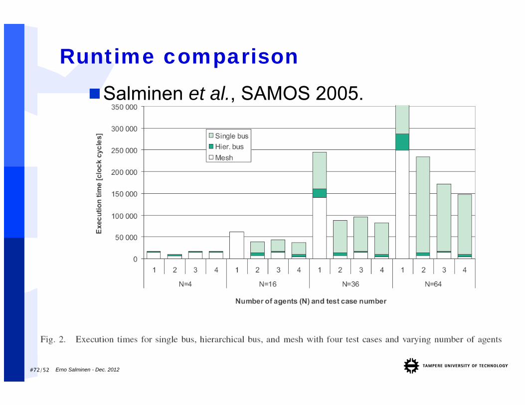
Runtime comparisonSalminen et al., SAMOS 2005.
Erno Salminen - Dec. 2012
Other notes on NoC
#74/52 Erno Salminen - Dec. 2012
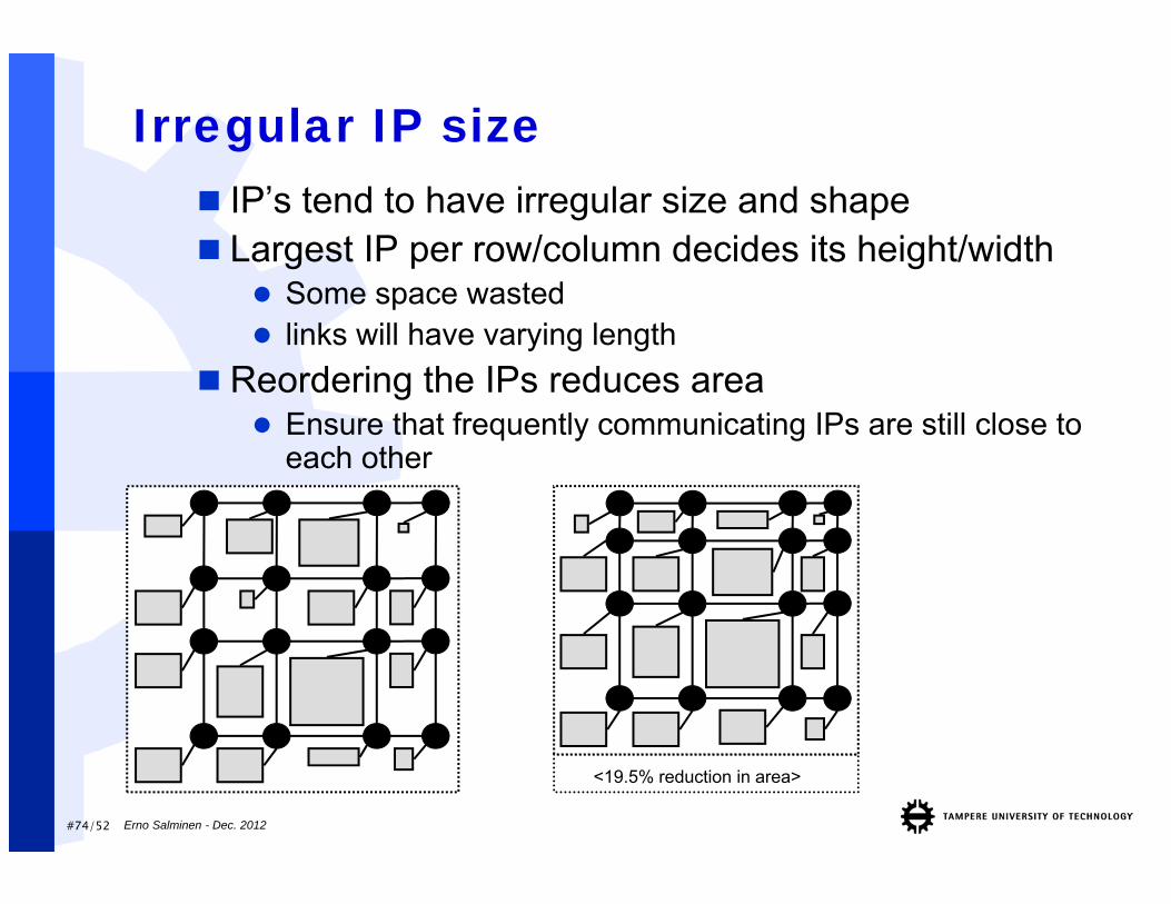
Irregular IP size
<19.5% reduction in area>
IP’s tend to have irregular size and shape Largest IP per row/column decides its height/width
Some space wasted links will have varying length
Reordering the IPs reduces area Ensure that frequently communicating IPs are still close to
each other
#75/52 Erno Salminen - Dec. 2012
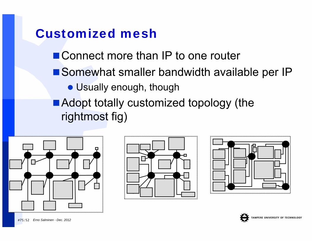
Customized meshConnect more than IP to one routerSomewhat smaller bandwidth available per IP Usually enough, though
Adopt totally customized topology (the rightmost fig)
#76/52 Erno Salminen - Dec. 2012
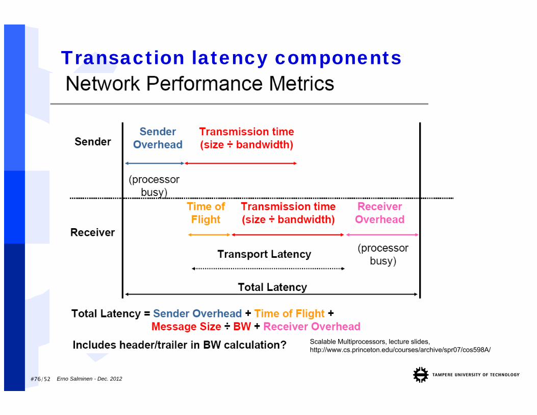
Transaction latency components
Scalable Multiprocessors, lecture slides, http://www.cs.princeton.edu/courses/archive/spr07/cos598A/
#77/52 Erno Salminen - Dec. 2012
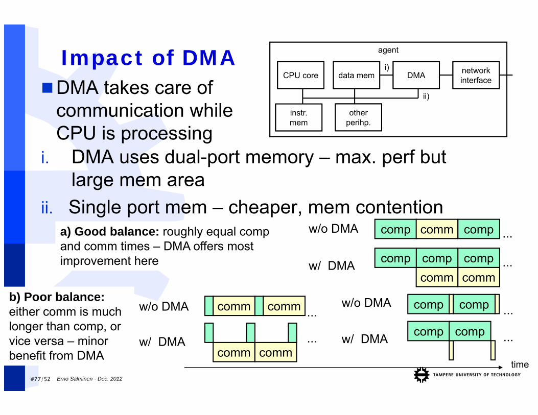
Impact of DMA
comp comp ...w/o DMA
compw/ DMA
comp comm comp ...w/o DMA
compcommcomp
comm...compw/ DMA
a) Good balance: roughly equal comp and comm times – DMA offers most improvement here
comm comm ...w/o DMA
comm comm...w/ DMA
b) Poor balance: either comm is much longer than comp, or vice versa – minor benefit from DMA
comp ...
agent
CPU core
instr. mem
data mem DMA network interface
other perihp.
ii)
i)
DMA takes care of communication while CPU is processing
i. DMA uses dual-port memory – max. perf but large mem area
ii. Single port mem – cheaper, mem contention
time
#78/52 Erno Salminen - Dec. 2012
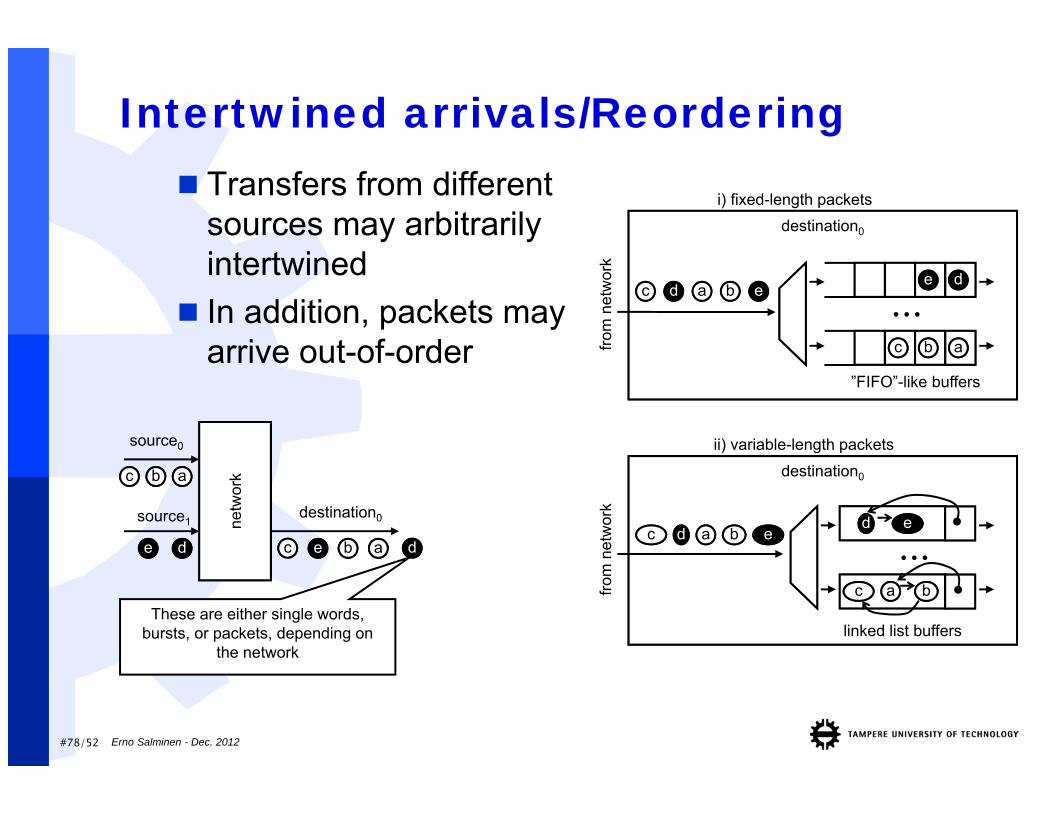
Intertwined arrivals/Reordering Transfers from different
sources may arbitrarily intertwined
In addition, packets may arrive out-of-order
netw
ork
source0
source1destination0
aabbcc
ddee ddaabbeecc
These are either single words, bursts, or packets, depending on
the network
destination0
...ddee
aabbcc
i) fixed-length packets
dd aa bb eecc
”FIFO”-like buffers
from
net
wor
k
destination0
from
net
wor
k
...dd ee
ii) variable-length packets
dd aa bb eecc
cc
linked list buffers
aa bb

#79/52
Rx buffer reservation
Notification of the next tx
Reserve buffer
ACK
Actual data
(optional ACK)
Sender agent Receiver agent
Consume data
Notification token of the reserved buffer
Actual data
Sender agent Receiver agent
Reserved buffer
Reserve buffer etc.
(copy data)
Consume data
Observedtx duration
Observedtx duration
Receiver must allocate mem buffer(s) for received data Dynamic: sender requests a buffer prior to transfer (as in fig), increases latency
(data and roundtrip of req+ack), but uses mem more efficiently Static reservation: reserve buffers for expected senders and send them tokens
(=permission to send)
Erno Salminen - Dec. 2012
#80/52 Erno Salminen - Dec. 2012
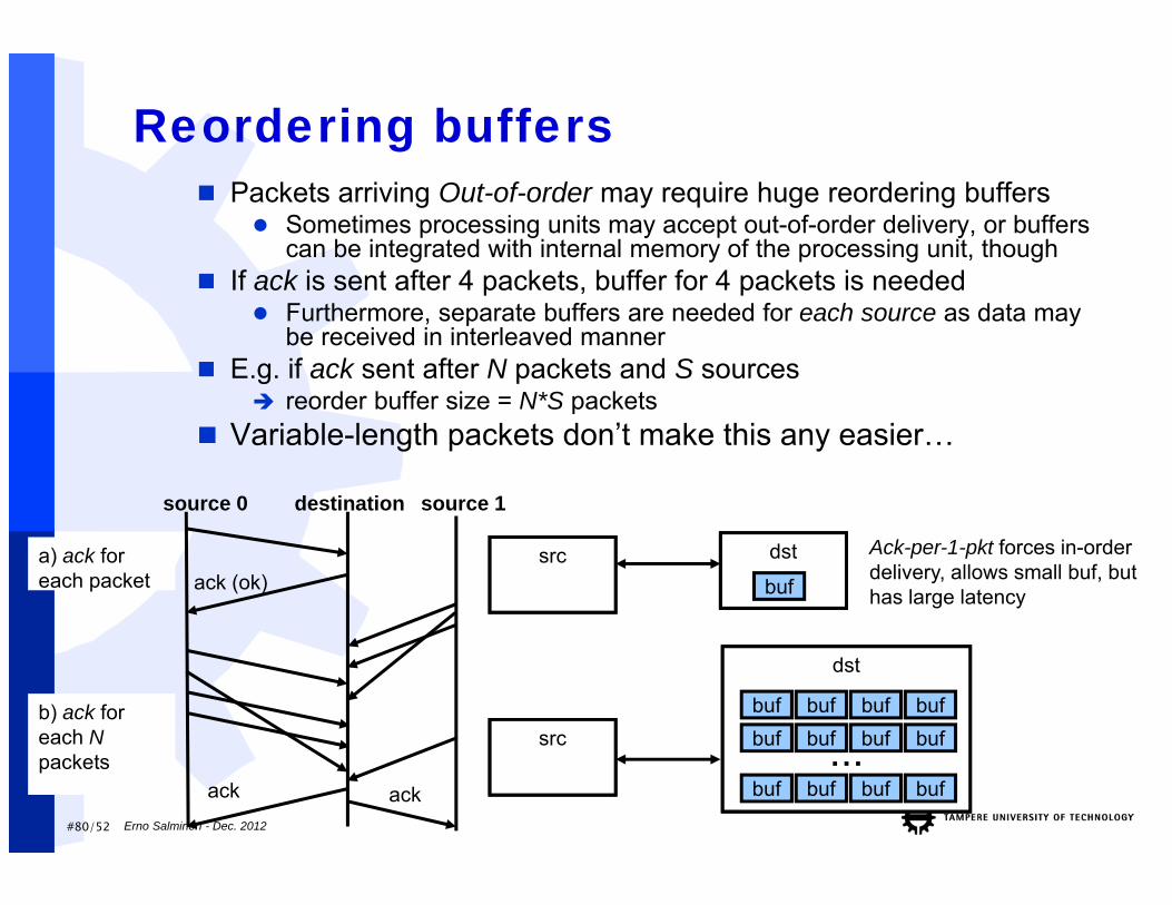
Reordering buffers Packets arriving Out-of-order may require huge reordering buffers
Sometimes processing units may accept out-of-order delivery, or buffers can be integrated with internal memory of the processing unit, though
If ack is sent after 4 packets, buffer for 4 packets is needed Furthermore, separate buffers are needed for each source as data may
be received in interleaved manner E.g. if ack sent after N packets and S sources
reorder buffer size = N*S packets Variable-length packets don’t make this any easier…
source 0 destination
ack (ok)
ack
a) ack for each packet
b) ack for each Npackets
src
dst
buf buf buf buf
dst
buf
src buf buf buf buf
buf buf buf buf...
Ack-per-1-pkt forces in-order delivery, allows small buf, but has large latency
source 1
ack
#81/52 Erno Salminen - Dec. 2012
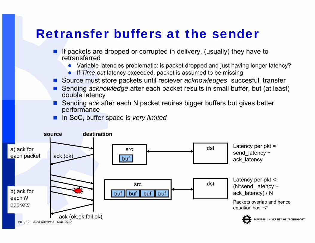
Retransfer buffers at the sender If packets are dropped or corrupted in delivery, (usually) they have to
retransferred Variable latencies problematic: is packet dropped and just having longer latency? If Time-out latency exceeded, packet is assumed to be missing
Source must store packets until reciever acknowledges succesfull transfer Sending acknowledge after each packet results in small buffer, but (at least)
double latency Sending ack after each N packet reuires bigger buffers but gives better
performance In SoC, buffer space is very limited
source destination
ack (ok)
ack (ok,ok,fail,ok)
a) ack for each packet
b) ack for each Npackets
src
buf
src
buf buf buf buf
dst
dst
Latency per pkt = send_latency + ack_latency
Latency per pkt < (N*send_latency + ack_latency) / NPackets overlap and hence equation has ”<”
#82/52 Erno Salminen - Dec. 2012
Wiring hierarchy
[H. Corporaal, Advanced Computer Architecture5Z008 - Multiprocessors &Interconnect, course material, 2003]
global
intermediate
local
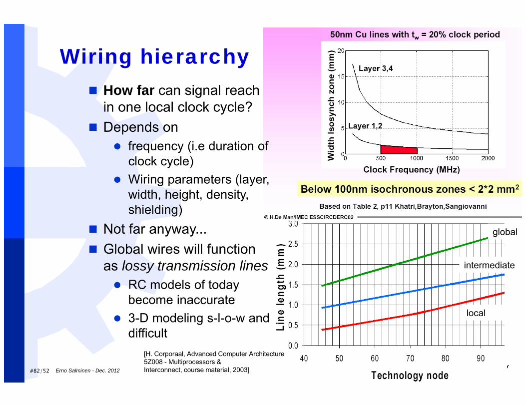
How far can signal reach in one local clock cycle?
Depends on frequency (i.e duration of
clock cycle) Wiring parameters (layer,
width, height, density, shielding)
Not far anyway... Global wires will function
as lossy transmission lines RC models of today
become inaccurate 3-D modeling s-l-o-w and
difficult
#83/52 Erno Salminen - Dec. 2012
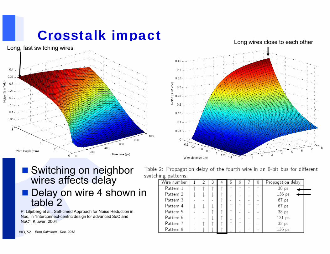
P. Liljeberg et al., Self-timed Approach for Noise Reduction in Noc, in “Interconnect-centric design for advanced SoC and NoC”, Kluwer. 2004
Crosstalk impactLong, fast switching wires
Long wires close to each other
Switching on neighbor wires affects delay
Delay on wire 4 shown in table 2