Embed Size (px)
Citation preview
8/14/2019 TM 5-3800-205-23-2 MODEL 613CS
http://slidepdf.com/reader/full/tm-5-3800-205-23-2-model-613cs 1/276
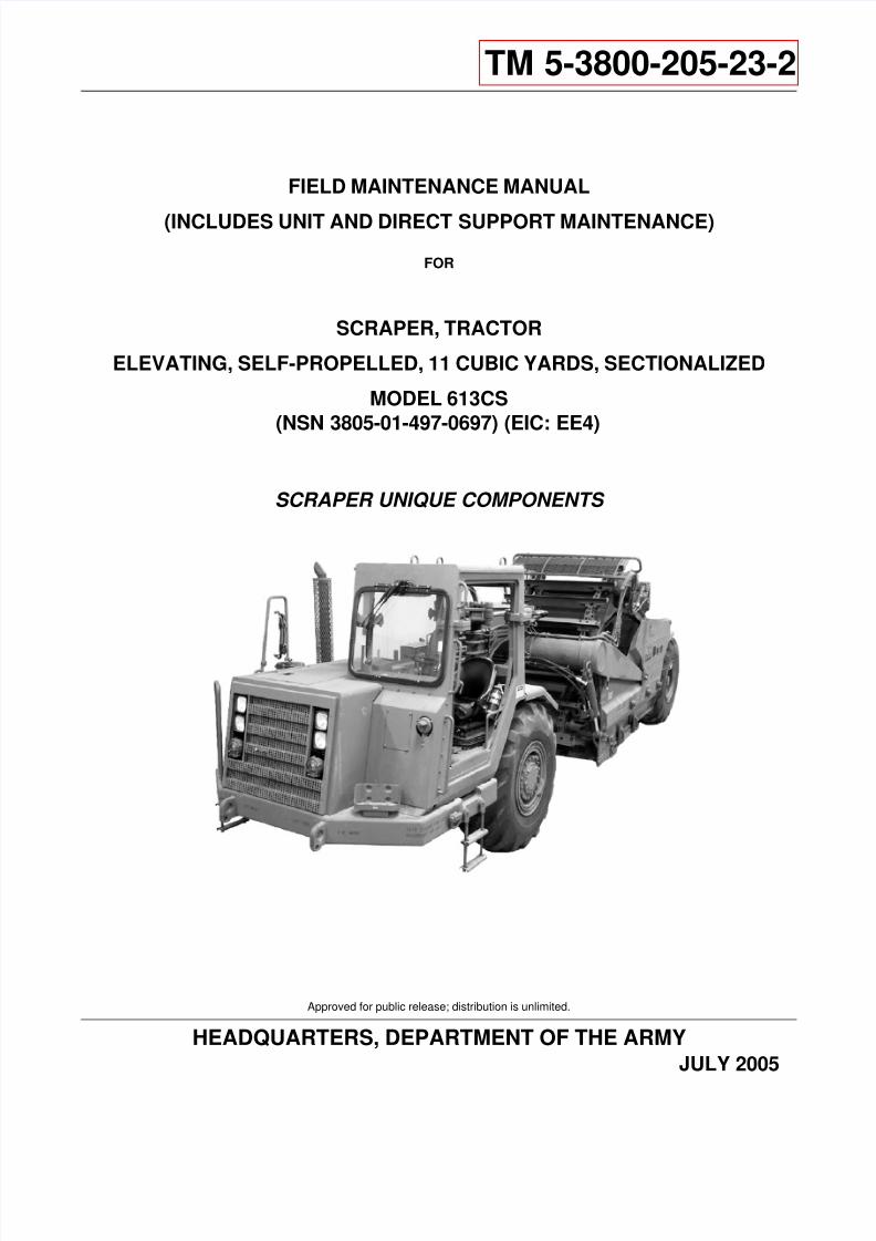
TM 5-3800-205-23-2
FIELD MAINTENANCE MANUAL
(INCLUDES UNIT AND DIRECT SUPPORT MAINTENANCE)
FOR
SCRAPER, TRACTOR
ELEVATING, SELF-PROPELLED, 11 CUBIC YARDS, SECTIONALIZED
MODEL 613CS
(NSN 3805-01-497-0697) (EIC: EE4)
SCRAPER UNIQUE COMPONENTS
Approved for public release; distribution is unlimited.
HEADQUARTERS, DEPARTMENT OF THE ARMY JULY 2005

8/14/2019 TM 5-3800-205-23-2 MODEL 613CS
http://slidepdf.com/reader/full/tm-5-3800-205-23-2-model-613cs 2/276
only Left Blank.
This page is blank.
8/14/2019 TM 5-3800-205-23-2 MODEL 613CS
http://slidepdf.com/reader/full/tm-5-3800-205-23-2-model-613cs 3/276
TM 5-3800-205-23-2
a
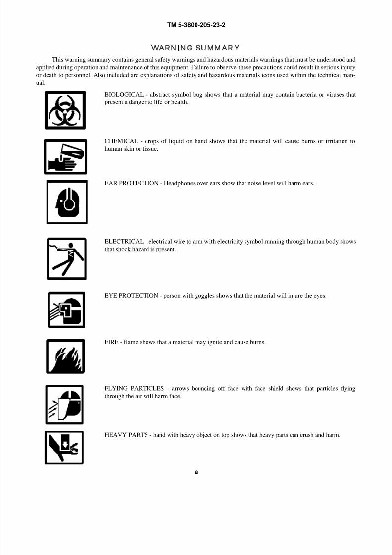
WARNING SUMMARY
This warning summary contains general safety warnings and hazardous materials warnings that must be understood and
applied during operation and maintenance of this equipment. Failure to observe these precautions could result in serious injury
or death to personnel. Also included are explanations of safety and hazardous materials icons used within the technical man-
ual.
BIOLOGICAL - abstract symbol bug shows that a material may contain bacteria or viruses thatpresent a danger to life or health.
CHEMICAL - drops of liquid on hand shows that the material will cause burns or irritation to
human skin or tissue.
EAR PROTECTION - Headphones over ears show that noise level will harm ears.
ELECTRICAL - electrical wire to arm with electricity symbol running through human body shows
that shock hazard is present.
EYE PROTECTION - person with goggles shows that the material will injure the eyes.
FIRE - flame shows that a material may ignite and cause burns.
FLYING PARTICLES - arrows bouncing off face with face shield shows that particles flyingthrough the air will harm face.
HEAVY PARTS - hand with heavy object on top shows that heavy parts can crush and harm.
8/14/2019 TM 5-3800-205-23-2 MODEL 613CS
http://slidepdf.com/reader/full/tm-5-3800-205-23-2-model-613cs 4/276
TM 5-3800-205-23-2
b
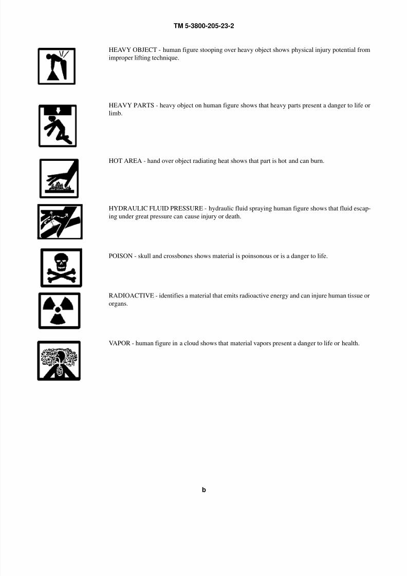
HEAVY OBJECT - human figure stooping over heavy object shows physical injury potential from
improper lifting technique.
HEAVY PARTS - heavy object on human figure shows that heavy parts present a danger to life or
limb.
HOT AREA - hand over object radiating heat shows that part is hot and can burn.
HYDRAULIC FLUID PRESSURE - hydraulic fluid spraying human figure shows that fluid escap-
ing under great pressure can cause injury or death.
POISON - skull and crossbones shows material is poinsonous or is a danger to life.
RADIOACTIVE - identifies a material that emits radioactive energy and can injure human tissue or
organs.
VAPOR - human figure in a cloud shows that material vapors present a danger to life or health.
8/14/2019 TM 5-3800-205-23-2 MODEL 613CS
http://slidepdf.com/reader/full/tm-5-3800-205-23-2-model-613cs 5/276
TM 5-3800-205-23-2
c
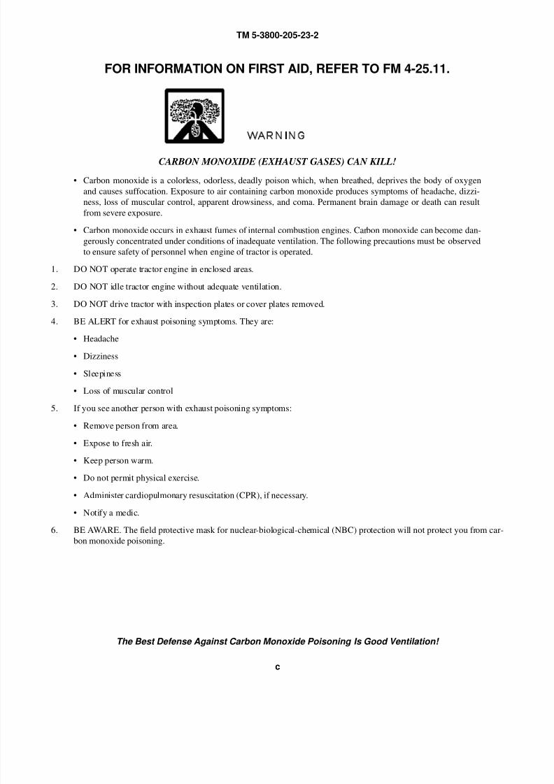
FOR INFORMATION ON FIRST AID, REFER TO FM 4-25.11.
WARNING
CARBON MONOXIDE (EXHAUST GASES) CAN KILL!
• Carbon monoxide is a colorless, odorless, deadly poison which, when breathed, deprives the body of oxygen
and causes suffocation. Exposure to air containing carbon monoxide produces symptoms of headache, dizzi-
ness, loss of muscular control, apparent drowsiness, and coma. Permanent brain damage or death can result
from severe exposure.
• Carbon monoxide occurs in exhaust fumes of internal combustion engines. Carbon monoxide can become dan-
gerously concentrated under conditions of inadequate ventilation. The following precautions must be observed
to ensure safety of personnel when engine of tractor is operated.
1. DO NOT operate tractor engine in enclosed areas.
2. DO NOT idle tractor engine without adequate ventilation.
3. DO NOT drive tractor with inspection plates or cover plates removed.
4. BE ALERT for exhaust poisoning symptoms. They are:
• Headache
• Dizziness
• Sleepiness
• Loss of muscular control
5. If you see another person with exhaust poisoning symptoms:
• Remove person from area.
• Expose to fresh air.
• Keep person warm.
• Do not permit physical exercise.
• Administer cardiopulmonary resuscitation (CPR), if necessary.
• Notify a medic.
6. BE AWARE. The field protective mask for nuclear-biological-chemical (NBC) protection will not protect you from car-
bon monoxide poisoning.
The Best Defense Against Carbon Monoxide Poisoning Is Good Ventilation!
8/14/2019 TM 5-3800-205-23-2 MODEL 613CS
http://slidepdf.com/reader/full/tm-5-3800-205-23-2-model-613cs 6/276
TM 5-3800-205-23-2
d
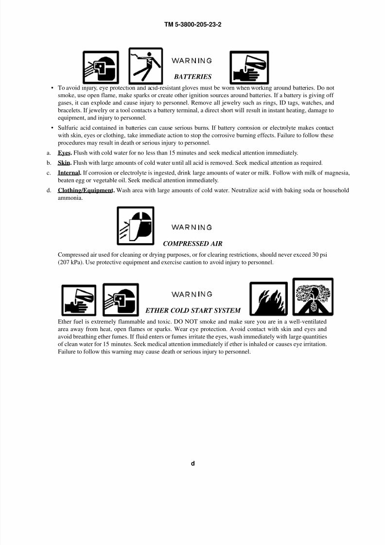
WARNING
BATTERIES
• To avoid injury, eye protection and acid-resistant gloves must be worn when working around batteries. Do not
smoke, use open flame, make sparks or create other ignition sources around batteries. If a battery is giving off gases, it can explode and cause injury to personnel. Remove all jewelry such as rings, ID tags, watches, and
bracelets. If jewelry or a tool contacts a battery terminal, a direct short will result in instant heating, damage to
equipment, and injury to personnel.
• Sulfuric acid contained in batteries can cause serious burns. If battery corrosion or electrolyte makes contact
with skin, eyes or clothing, take immediate action to stop the corrosive burning effects. Failure to follow these
procedures may result in death or serious injury to personnel.
a. Eyes. Flush with cold water for no less than 15 minutes and seek medical attention immediately.
b. Skin. Flush with large amounts of cold water until all acid is removed. Seek medical attention as required.
c. Internal. If corrosion or electrolyte is ingested, drink large amounts of water or milk. Follow with milk of magnesia,
beaten egg or vegetable oil. Seek medical attention immediately.
d. Clothing/Equipment. Wash area with large amounts of cold water. Neutralize acid with baking soda or householdammonia.
WARNING
COMPRESSED AIR
Compressed air used for cleaning or drying purposes, or for clearing restrictions, should never exceed 30 psi
(207 kPa). Use protective equipment and exercise caution to avoid injury to personnel.
WARNING
ETHER COLD START SYSTEM
Ether fuel is extremely flammable and toxic. DO NOT smoke and make sure you are in a well-ventilated
area away from heat, open flames or sparks. Wear eye protection. Avoid contact with skin and eyes and
avoid breathing ether fumes. If fluid enters or fumes irritate the eyes, wash immediately with large quantities
of clean water for 15 minutes. Seek medical attention immediately if ether is inhaled or causes eye irritation.
Failure to follow this warning may cause death or serious injury to personnel.
8/14/2019 TM 5-3800-205-23-2 MODEL 613CS
http://slidepdf.com/reader/full/tm-5-3800-205-23-2-model-613cs 7/276
TM 5-3800-205-23-2
e
WARNING
FUEL HANDLING
• DO NOT smoke or permit any open flame in area of machine while you are servicing fuel system. Be sure hose
nozzle is grounded against filler tube during refueling to prevent static electricity. Failure to follow this warn-
ing may result in injury to personnel or equipment damage.
• DO NOT perform fuel system checks, inspections or maintenance while smoking or near fire, flames or sparks.
Fuel may ignite, causing damage to machine and injury or death to personnel.
• Operating personnel must wear fuel-resistant gloves when handling fuels. If exposed to fuel, promptly wash
exposed skin and change fuel-soaked clothing. Failure to follow this warning may result in injury to personnel.
WARNING
HAZARDOUS WASTE DISPOSAL
When servicing this machine, performing maintenance, or disposing of materials such as engine coolant,
hydraulic fluid, lubricants, battery acids or batteries, and CARC paint, consult your unit/local hazardous
waste disposal center or safety office for local regulatory guidance. If further information is needed, please
contact The Army Environmental Hotline at 1-800-872-3845.
WARNING
HEARING PROTECTION
Hearing protection is required when operating machine or when within 23 feet of machine when it is operat-
ing. Failure to wear hearing protection may result in hearing loss.
WARNING
HYDRAULIC SYSTEM
• Do NOT disconnect or remove any hydraulic system line or fitting unless engine is shut down and hydraulic
system pressure has been relieved. Tighten all connections before applying pressure. Escaping hydraulic fluid
under pressure can penetrate the skin, causing serious injury.
• At operating temperature, hydraulic oil is hot. Allow hydraulic oil to cool before disconnecting any hydraulic
lines. Failure to do so could result in injury.
WARNING
ISU-60 CONTAINER
Never transport container with doors open. Transporting container with doors open may cause serious injury
or death to personnel.
8/14/2019 TM 5-3800-205-23-2 MODEL 613CS
http://slidepdf.com/reader/full/tm-5-3800-205-23-2-model-613cs 8/276
TM 5-3800-205-23-2
f
WARNING
NBC EXPOSURE
If NBC exposure is suspected, personnel wearing protective equipment should handle all air cleaner media.
Consult your NBC Officer or NBC NCO for appropriate handling or disposal procedures. Failure to follow
this warning may result in illness or death to personnel.
• NBC contaminated filters must be handled using adequate precautions (FM 21-40) and must be disposed of by
trained personnel. Failure to follow this warning may result in illness or death to personnel.
To order this NBC decal use:
National Stock Number (NSN) - 7690-01-114-3702
Part Number (PN) - 12296626
Commercial and Government Entity Code (CAGEC) - 19207
WARNING
IF NBC EXPOSURE IS SUSPECTED ALL AIR
FILTER MEDIA WILL BE HANDLED BY PER-
SONNEL WEARING FULL NBC PROTEC-
TIVE EQUIPMENT. SEE OPERATOR/
MAINTENANCE MANUAL.7690-01-114-3702
8/14/2019 TM 5-3800-205-23-2 MODEL 613CS
http://slidepdf.com/reader/full/tm-5-3800-205-23-2-model-613cs 9/276
TM 5-3800-205-23-2
g
WARNING
OPERATION SAFETY
• Use caution and maintain three-point contact at all times when mounting and dismounting machine, to avoid
injury to personnel.• DO NOT allow riders on the tractor. Failure to follow this warning may result in serious injury or death to per-
sonnel.
• DO NOT operate machine unless seat belt has been fastened. Failure to follow this warning may result in seri-
ous injury or death, in the event of an accident.
• BE ALERT for personnel in the area while operating machine. Always check to ensure area is clear of person-
nel and obstructions before starting engine, moving machine or lowering or raising scraper bowl. Failure to fol-
low this warning may result in serious injury or death to personnel or damage to equipment.
• Never leave the operator’s position without applying the parking brake. Failure to follow this warning may
result in death or injury to personnel or damage to equipment.
• Never use starting fluid or spray to aid in starting the engine other than the on-board ether cold start system.
Failure to follow this warning may result in death or injury to personnel or damage to equipment.
• Always use a ground guide when driving machine up or down ramps in preparation for highway, marine or airtransport, or when driving tractor into position for assembly to scraper. Failure to use a ground guide may result
in an accident, causing death or injury to personnel or damage to equipment.
• When loaded and traveling across a hillside, reduce speed significantly BEFORE turning uphill. Failure to do
so may cause machine to roll over, resulting in injury or death to personnel.
• Do NOT operate machine if parking brake was applied due to a malfunction of airbrake system or parking
brake. Correct any problem before attempting to operate machine. Personal injury or death can result from a
brake malfunction.
• For Water Distributor only, DO NOT operate machine at speeds greater than 18 mph (29 kph), in all weather
and road conditions and fully loaded. Maximum operating time at 18 mph (29 kph) is 7 hours within a 24-hour
period. Failure to follow this warning may cause external or internal injury due to excessive whole-body vibra-
tion.
8/14/2019 TM 5-3800-205-23-2 MODEL 613CS
http://slidepdf.com/reader/full/tm-5-3800-205-23-2-model-613cs 10/276
TM 5-3800-205-23-2
h
WARNING
PREPARATION FOR TRANSPORT
• Use extreme caution when handling heavy parts. Provide adequate support and use assistance during proce-
dure. Ensure that any lifting device used is in good condition and of suitable lift capacity. Keep clear of heavy
parts supported only by lifting device. Failure to follow this warning may result in death or injury to personnel.
• If operating machine without ROPS/FOPS, drive with extreme caution, at low idle, and in 1st gear or reverse
ONLY. Machine has no rollover/falling object protection without ROPS/FOPS. Failure to follow this warning
may cause injury or death to personnel or damage to equipment.
• Always use a ground guide when moving machine during preparation for transport procedures (driving up and
down ramps, onto airdrop platform or onto rail flatcars). Failure to use a ground guide may result in an acci-
dent, causing death or injury to personnel or damage to equipment.
• Use extreme caution when driving sectionalized tractor with stability skids and no ROPS/FOPS. Use first gearforward or reverse and low idle ONLY. Ground guide or ground safety officer assistance is required to monitor
path in front of front stability skid, to avoid obstacles and direct tractor operation. Failure to follow this warn-
ing may result in injury or death to personnel or damage to equipment.
• Use assistance and handle windshield with caution to ensure it does not become damaged. Failure to do so may
damage windshield or cause personnel injury from cut glass if windshield breaks.
• Use extreme caution when climbing on ladder. Failure to exercise caution may result in a fall, causing injury to
personnel.
• Removal of upper handrail on right side of tractor leaves right side of tractor without any means to safely climb
on machine. Use caution when climbing on right side if upper handrail has been removed. Failure to do so may
result in injury to personnel.
• Do NOT remove exhaust stack until it has cooled to the touch. Wear gloves and protective cloth-
ing as required to guard against burns. Failure to follow this warning may cause personnel injury.
WARNING
PRESSURIZED AIR
• Do NOT disconnect any air system lines or fittings unless engine is shut down and air system pressure is
relieved. Failure to follow this warning could result in serious injury to personnel.
• Always wear eye protection when disconnecting air lines. Residual air will be expelled. Failure to follow this
warning may result in serious eye injury.
8/14/2019 TM 5-3800-205-23-2 MODEL 613CS
http://slidepdf.com/reader/full/tm-5-3800-205-23-2-model-613cs 11/276
TM 5-3800-205-23-2
i
WARNING
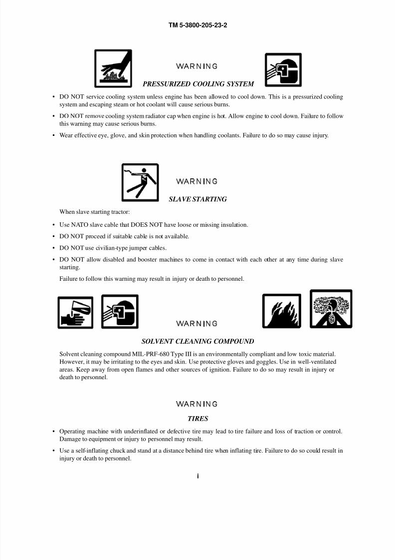
PRESSURIZED COOLING SYSTEM
• DO NOT service cooling system unless engine has been allowed to cool down. This is a pressurized coolingsystem and escaping steam or hot coolant will cause serious burns.
• DO NOT remove cooling system radiator cap when engine is hot. Allow engine to cool down. Failure to follow
this warning may cause serious burns.
• Wear effective eye, glove, and skin protection when handling coolants. Failure to do so may cause injury.
WARNING
SLAVE STARTING
When slave starting tractor:
• Use NATO slave cable that DOES NOT have loose or missing insulation.
• DO NOT proceed if suitable cable is not available.
• DO NOT use civilian-type jumper cables.
• DO NOT allow disabled and booster machines to come in contact with each other at any time during slave
starting.
Failure to follow this warning may result in injury or death to personnel.
WARNING
SOLVENT CLEANING COMPOUND
Solvent cleaning compound MIL-PRF-680 Type III is an environmentally compliant and low toxic material.
However, it may be irritating to the eyes and skin. Use protective gloves and goggles. Use in well-ventilated
areas. Keep away from open flames and other sources of ignition. Failure to do so may result in injury or
death to personnel.
WARNING
TIRES
• Operating machine with underinflated or defective tire may lead to tire failure and loss of traction or control.
Damage to equipment or injury to personnel may result.
• Use a self-inflating chuck and stand at a distance behind tire when inflating tire. Failure to do so could result in
injury or death to personnel.

8/14/2019 TM 5-3800-205-23-2 MODEL 613CS
http://slidepdf.com/reader/full/tm-5-3800-205-23-2-model-613cs 12/276
TM 5-3800-205-23-2
j
WARNING
WORK SAFETY
• Lifting cables, chains, hooks, and slings used for lifting machine must be in good condition and of
suitable capacity. Failure to follow this warning may result in injury or death to personnel and
damage to equipment.
• Improper use of lifting equipment and improper attachment of cables to machine can result in seri-
ous personnel injury and equipment damage. Observe all standard rules of safety.
• Hitch and steering movement can reduce clearances suddenly and cause personnel injury. Always stop engine
BEFORE working in area of hitch link.
• Configuration changes to cutting edge and cutting edge-to-elevator clearance adjustments should NEVER be
attempted without first securing the bowl by blocking it so that it is firmly supported. Failure to follow this
warning may cause injury to personnel.• Use extreme caution when handling heavy parts. Provide adequate support and use assistance dur-
ing procedure. Ensure that any lifting device used is in good condition and of suitable load capac-
ity. Keep clear of heavy parts supported only by lifting device. Failure to follow this warning may
result in death or injury to personnel.
8/14/2019 TM 5-3800-205-23-2 MODEL 613CS
http://slidepdf.com/reader/full/tm-5-3800-205-23-2-model-613cs 13/276
TM 5-3800-205-23-2
A
LIST OF EFFECTIVE PAGES/WORK PACKAGES
Date of issue for original manual is:
Original 15 July 2005
TOTAL NUMBER OF PAGES FOR FRONT AND REAR MATTER IS 36 AND TOTAL NUMBER OF WORKPACKAGES IS 51 CONSISTING OF THE FOLLOWING:
Page/WP *Change
No. No.
Cover/(Back Blank) 0
a to h 0
A (B Blank) 0
i to vi 0
WP 0001 to WP 0051 0
Index-1 to Index-4 0
* Zero in this column indicates an original page or work package.

8/14/2019 TM 5-3800-205-23-2 MODEL 613CS
http://slidepdf.com/reader/full/tm-5-3800-205-23-2-model-613cs 14/276
TM 5-3800-205-23-2
B
This Page Intentionally Left Blank.
8/14/2019 TM 5-3800-205-23-2 MODEL 613CS
http://slidepdf.com/reader/full/tm-5-3800-205-23-2-model-613cs 15/276
TM 5-3800-205-23-2
i
TECHNICAL MANUAL HEADQUARTERSTM 5-3800-205-23-2 DEPARTMENT OF THE ARMY
Washington, D.C., 15 July 2005
TECHNICAL MANUAL
(INCLUDES UNIT AND DIRECT SUPPORT FIELD MAINTENANCE MANUAL)
FOR
SCRAPER, TRACTOR
ELEVATING, SELF-PROPELLED, 11 CUBIC YARDS, SECTIONALIZED
MODEL 613CS
(NSN 3805-01-497-0697) (EIC:EE4)
SCRAPER UNIQUE COMPONENTS
Table of Contents
Volume 2 TM 5-3800-205-23-2
Page
Number
Warning Summary. . . . . . . . . . . . . . . . . . . . . . . . . . . . . . . . . . . . . . . . . . . . . . . . . . . . . . . a
How To Use This Manual . . . . . . . . . . . . . . . . . . . . . . . . . . . . . . . . . . . . . . . . . . . . . . . . . v
CHAPTER 1 UNIT LEVEL SCRAPER MAINTENANCE
Fuel System
WP 0001 00 Fuel Pump, Hoses, and Tubes Replacement . . . . . . . . . . . . . . . . . . . . . . . . . . . 0001 00-1
WP 0002 00 Fuel/Water Separator Replacement. . . . . . . . . . . . . . . . . . . . . . . . . . . . . . . . . . 0002 00-1
Electrical System
WP 0003 00 Electrical General Maintenance Instructions. . . . . . . . . . . . . . . . . . . . . . . . . . . 0003 00-1
WP 0004 00 Ground Straps Replacement . . . . . . . . . . . . . . . . . . . . . . . . . . . . . . . . . . . . . . . 0004 00-1
WP 0005 00 Composite Light Maintenance . . . . . . . . . . . . . . . . . . . . . . . . . . . . . . . . . . . . . . 0005 00-1
WP 0006 00 Blackout Light Maintenance . . . . . . . . . . . . . . . . . . . . . . . . . . . . . . . . . . . . . . . 0006 00-1
REPORTING ERRORS AND RECOMMENDING IMPROVEMENTSYou can help improve this publication. If you find any mistakes or if you know of a way to improve the pro-
cedures, please let us know. Submit your DA Form 2028 ( Recommended Changes to Equipment Technical
Publications), through the Internet, on the Army Electronic Product Support (AEPS) website. The Internet
address is http://aeps.ria.army.mil. If you need a password, scroll down and click on “ACCESS REQUEST
FORM”. The DA Form 2028 is located in the ONLINE FORMS PROCESSING section of the AEPS. Fill
out the form and click on SUBMIT. Using this form on the AEPS will enable us to respond quicker to your
comments and better manage the DA Form 2028 program. You may also mail, fax or e-mail your letter, DA
Form 2028 direct to: AMSTA-LC-CI/TECH PUBS, TACOM-RI, 1 Rock Island Arsenal, Rock Island, IL
61299-7630. The e-mail address is: [email protected]. The fax number is DSN 793-
0726 or Commercial (309) 782-0726.
8/14/2019 TM 5-3800-205-23-2 MODEL 613CS
http://slidepdf.com/reader/full/tm-5-3800-205-23-2-model-613cs 16/276
TM 5-3800-205-23-2
ii
Table of Contents - Continued
PageNumber
Electrical System - Continued
WP 0007 00 Fuel Level Sending Unit and Dial Sensor Replacement . . . . . . . . . . . . . . . . . 0007 00-1
WP 0008 00 Backup Alarm Replacement . . . . . . . . . . . . . . . . . . . . . . . . . . . . . . . . . . . . . . . 0008 00-1
Axles
WP 0009 00 Rear Hub and Disc Replacement. . . . . . . . . . . . . . . . . . . . . . . . . . . . . . . . . . . . 0009 00-1
Brake System
WP 0010 00 Air/Hydraulic Brake Cylinder Replacement . . . . . . . . . . . . . . . . . . . . . . . . . . . 0010 00-1
WP 0011 00 Rear Service Brakeshoes and Caliper Replacement . . . . . . . . . . . . . . . . . . . . . 0011 00-1
WP 0012 00 Air Hoses and Tubes Replacement . . . . . . . . . . . . . . . . . . . . . . . . . . . . . . . . . . 0012 00-1
WP 0013 00 Quick-Release Valve Replacement . . . . . . . . . . . . . . . . . . . . . . . . . . . . . . . . . . 0013 00-1
WP 0014 00 Brake Lines Replacement . . . . . . . . . . . . . . . . . . . . . . . . . . . . . . . . . . . . . . . . . 0014 00-1
WP 0015 00 Service Brakes Bleeding . . . . . . . . . . . . . . . . . . . . . . . . . . . . . . . . . . . . . . . . . . 0015 00-1
Wheel and Tire
WP 0016 00 Rear Tire and Rim Replacement . . . . . . . . . . . . . . . . . . . . . . . . . . . . . . . . . . . . 0016 00-1
Body and Cab
WP 0017 00 Toolbox and Rear Deck Cover Replacement . . . . . . . . . . . . . . . . . . . . . . . . . . 0017 00-1
Body and Accessory Items
WP 0018 00 Data Plate Replacement. . . . . . . . . . . . . . . . . . . . . . . . . . . . . . . . . . . . . . . . . . . 0018 00-1
Hydraulic System
WP 0019 00 Elevator Motor Replacement. . . . . . . . . . . . . . . . . . . . . . . . . . . . . . . . . . . . . . . 0019 00-1
WP 0020 00 Hydraulic Lines and Fittings Replacement . . . . . . . . . . . . . . . . . . . . . . . . . . . . 0020 00-1
WP 0021 00 Check Valve and Lift Cylinder Replacement . . . . . . . . . . . . . . . . . . . . . . . . . . 0021 00-1
Scraper System
WP 0022 00 Elevator Assembly Adjustment. . . . . . . . . . . . . . . . . . . . . . . . . . . . . . . . . . . . . 0022 00-1
WP 0023 00 Elevator Flights and Chains Replacement. . . . . . . . . . . . . . . . . . . . . . . . . . . . . 0023 00-1
WP 0024 00 Elevator Guard Replacement. . . . . . . . . . . . . . . . . . . . . . . . . . . . . . . . . . . . . . . 0024 00-1
WP 0025 00 Elevator Chain Adjustment . . . . . . . . . . . . . . . . . . . . . . . . . . . . . . . . . . . . . . . . 0025 00-1
WP 0026 00 Elevator Chain Idler Replacement. . . . . . . . . . . . . . . . . . . . . . . . . . . . . . . . . . . 0026 00-1
WP 0027 00 Ejector Clearance Adjustment. . . . . . . . . . . . . . . . . . . . . . . . . . . . . . . . . . . . . . 0027 00-1
WP 0028 00 Cutting Edges and Router Bits Replacement . . . . . . . . . . . . . . . . . . . . . . . . . . 0028 00-1
CHAPTER 2 DIRECT SUPPORT LEVEL SCRAPER MAINTENANCE
Axles
WP 0029 00 Rear Wheel Bearings and Seal Replacement . . . . . . . . . . . . . . . . . . . . . . . . . . 0029 00-1
Hydraulic System
WP 0030 00 Floor Check Valve Replacement. . . . . . . . . . . . . . . . . . . . . . . . . . . . . . . . . . . . 0030 00-1
WP 0031 00 Ejector Cylinder Replacement. . . . . . . . . . . . . . . . . . . . . . . . . . . . . . . . . . . . . . 0031 00-1
WP 0032 00 Floor Cylinder Replacement . . . . . . . . . . . . . . . . . . . . . . . . . . . . . . . . . . . . . . . 0032 00-1
Scraper System
WP 0033 00 Elevator Assembly Replacement. . . . . . . . . . . . . . . . . . . . . . . . . . . . . . . . . . . . 0033 00-1
WP 0034 00 Elevator Chain Idler Repair. . . . . . . . . . . . . . . . . . . . . . . . . . . . . . . . . . . . . . . . 0034 00-1
8/14/2019 TM 5-3800-205-23-2 MODEL 613CS
http://slidepdf.com/reader/full/tm-5-3800-205-23-2-model-613cs 17/276
TM 5-3800-205-23-2
iii
Table of Contents - Continued
Page
Number
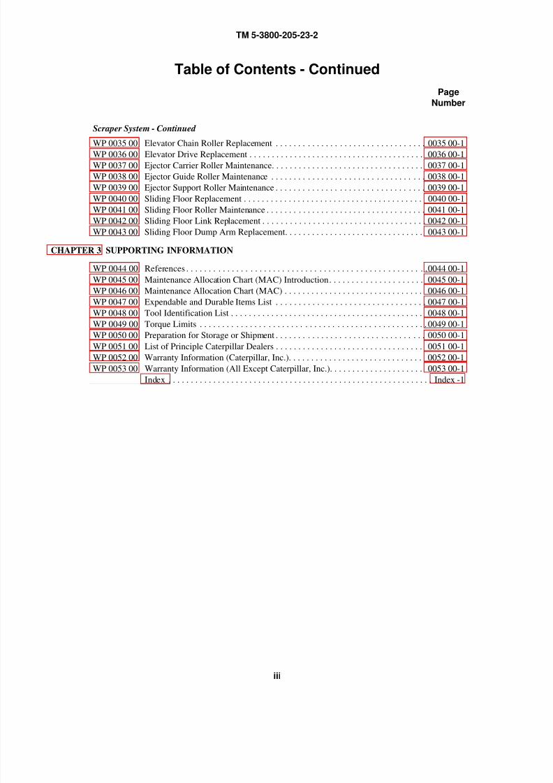
Scraper System - Continued
WP 0035 00 Elevator Chain Roller Replacement . . . . . . . . . . . . . . . . . . . . . . . . . . . . . . . . . 0035 00-1
WP 0036 00 Elevator Drive Replacement . . . . . . . . . . . . . . . . . . . . . . . . . . . . . . . . . . . . . . . 0036 00-1
WP 0037 00 Ejector Carrier Roller Maintenance. . . . . . . . . . . . . . . . . . . . . . . . . . . . . . . . . . 0037 00-1
WP 0038 00 Ejector Guide Roller Maintenance . . . . . . . . . . . . . . . . . . . . . . . . . . . . . . . . . . 0038 00-1
WP 0039 00 Ejector Support Roller Maintenance . . . . . . . . . . . . . . . . . . . . . . . . . . . . . . . . . 0039 00-1
WP 0040 00 Sliding Floor Replacement . . . . . . . . . . . . . . . . . . . . . . . . . . . . . . . . . . . . . . . . 0040 00-1
WP 0041 00 Sliding Floor Roller Maintenance . . . . . . . . . . . . . . . . . . . . . . . . . . . . . . . . . . . 0041 00-1
WP 0042 00 Sliding Floor Link Replacement . . . . . . . . . . . . . . . . . . . . . . . . . . . . . . . . . . . . 0042 00-1
WP 0043 00 Sliding Floor Dump Arm Replacement. . . . . . . . . . . . . . . . . . . . . . . . . . . . . . . 0043 00-1
CHAPTER 3 SUPPORTING INFORMATION
WP 0044 00 References . . . . . . . . . . . . . . . . . . . . . . . . . . . . . . . . . . . . . . . . . . . . . . . . . . . . . 0044 00-1
WP 0045 00 Maintenance Allocation Chart (MAC) Introduction. . . . . . . . . . . . . . . . . . . . . 0045 00-1
WP 0046 00 Maintenance Allocation Chart (MAC) . . . . . . . . . . . . . . . . . . . . . . . . . . . . . . . 0046 00-1
WP 0047 00 Expendable and Durable Items List . . . . . . . . . . . . . . . . . . . . . . . . . . . . . . . . . 0047 00-1
WP 0048 00 Tool Identification List . . . . . . . . . . . . . . . . . . . . . . . . . . . . . . . . . . . . . . . . . . . 0048 00-1
WP 0049 00 Torque Limits . . . . . . . . . . . . . . . . . . . . . . . . . . . . . . . . . . . . . . . . . . . . . . . . . . 0049 00-1
WP 0050 00 Preparation for Storage or Shipment . . . . . . . . . . . . . . . . . . . . . . . . . . . . . . . . . 0050 00-1
WP 0051 00 List of Principle Caterpillar Dealers . . . . . . . . . . . . . . . . . . . . . . . . . . . . . . . . . 0051 00-1
WP 0052 00 Warranty Information (Caterpillar, Inc.). . . . . . . . . . . . . . . . . . . . . . . . . . . . . . 0052 00-1
WP 0053 00 Warranty Information (All Except Caterpillar, Inc.). . . . . . . . . . . . . . . . . . . . . 0053 00-1
Index . . . . . . . . . . . . . . . . . . . . . . . . . . . . . . . . . . . . . . . . . . . . . . . . . . . . . . . . . . . Index -1

8/14/2019 TM 5-3800-205-23-2 MODEL 613CS
http://slidepdf.com/reader/full/tm-5-3800-205-23-2-model-613cs 18/276
TM 5-3800-205-23-2
iv
This Page Intentionally Left Blank.
8/14/2019 TM 5-3800-205-23-2 MODEL 613CS
http://slidepdf.com/reader/full/tm-5-3800-205-23-2-model-613cs 19/276
TM 5-3800-205-23-2
v
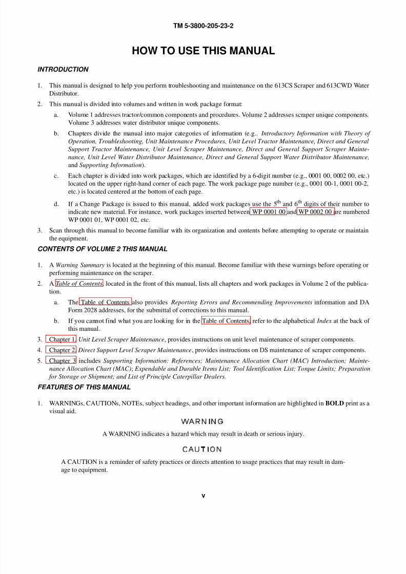
HOW TO USE THIS MANUAL
INTRODUCTION
1. This manual is designed to help you perform troubleshooting and maintenance on the 613CS Scraper and 613CWD Water
Distributor.
2. This manual is divided into volumes and written in work package format:
a. Volume 1 addresses tractor/common components and procedures. Volume 2 addresses scraper unique components.
Volume 3 addresses water distributor unique components.
b. Chapters divide the manual into major categories of information (e.g., Introductory Information with Theory of
Operation, Troubleshooting, Unit Maintenance Procedures, Unit Level Tractor Maintenance, Direct and General
Support Tractor Maintenance, Unit Level Scraper Maintenance, Direct and General Support Scraper Mainte-
nance, Unit Level Water Distributor Maintenance, Direct and General Support Water Distributor Maintenance,
and Supporting Information).
c. Each chapter is divided into work packages, which are identified by a 6-digit number (e.g., 0001 00, 0002 00, etc.)
located on the upper right-hand corner of each page. The work package page number (e.g., 0001 00-1, 0001 00-2,
etc.) is located centered at the bottom of each page.
d. If a Change Package is issued to this manual, added work packages use the 5th and 6th digits of their number to
indicate new material. For instance, work packages inserted between WP 0001 00 and WP 0002 00 are numbered
WP 0001 01, WP 0001 02, etc.
3. Scan through this manual to become familiar with its organization and contents before attempting to operate or maintain
the equipment.
CONTENTS OF VOLUME 2 THIS MANUAL
1. A Warning Summary is located at the beginning of this manual. Become familiar with these warnings before operating or
performing maintenance on the scraper.
2. A Table of Contents, located in the front of this manual, lists all chapters and work packages in Volume 2 of the publica-
tion.
a. The Table of Contents also provides Reporting Errors and Recommending Improvements information and DAForm 2028 addresses, for the submittal of corrections to this manual.
b. If you cannot find what you are looking for in the Table of Contents, refer to the alphabetical Index at the back of
this manual.
3. Chapter 1, Unit Level Scraper Maintenance, provides instructions on unit level maintenance of scraper components.
4. Chapter 2, Direct Support Level Scraper Maintenance, provides instructions on DS maintenance of scraper components.
5. Chapter 3 includes Supporting Information: References; Maintenance Allocation Chart (MAC) Introduction; Mainte-
nance Allocation Chart (MAC); Expendable and Durable Items List; Tool Identification List; Torque Limits; Preparation
for Storage or Shipment; and List of Principle Caterpillar Dealers.
FEATURES OF THIS MANUAL
1. WARNINGs, CAUTIONs, NOTEs, subject headings, and other important information are highlighted in BOLD print as avisual aid.
WARNING
A WARNING indicates a hazard which may result in death or serious injury.
CAUTION
A CAUTION is a reminder of safety practices or directs attention to usage practices that may result in dam-
age to equipment.

8/14/2019 TM 5-3800-205-23-2 MODEL 613CS
http://slidepdf.com/reader/full/tm-5-3800-205-23-2-model-613cs 20/276
TM 5-3800-205-23-2
vi
NOTE
A NOTE is a statement containing information that will make the procedures easier to perform.
2. Statements and words of particular interest may be printed in CAPITAL LETTERS to create emphasis.
3. Within a procedural step, reference may be made to another work package in this manual or to another manual. These ref-
erences indicate where you should look for more complete information.
If you are told: “Replace Fuel/Water Separator (WP 0020 00)”, go to Work Package 0020 00 in this manual for instruc-
tions on replacing the Fuel/Water Separator.
4. Illustrations are placed after, and as close to, the procedural steps to which they apply. Callouts placed on the art may be
text or numbers, or both; whichever method is easier for the soldier.
5. Numbers located at lower right corner of art (e.g. 390-001; 390-002, etc.) are art control numbers and are used for tracking
purposes. Disregard these numbers.
6. Technical instructions include metric units as well as standard units. For your reference, a Metric Conversion Chart is
located on the inside back cover of the manual.
NOTE
If at any time you are unsure how to use this manual or you cannot locate the information you need, notify
your supervisor.
8/14/2019 TM 5-3800-205-23-2 MODEL 613CS
http://slidepdf.com/reader/full/tm-5-3800-205-23-2-model-613cs 21/276
TM 5-3800-205-23-2
CHAPTER 1
UNIT LEVEL SCRAPER MAINTENANCE

8/14/2019 TM 5-3800-205-23-2 MODEL 613CS
http://slidepdf.com/reader/full/tm-5-3800-205-23-2-model-613cs 22/276
TM 5-3800-205-23-2
This Page Intentionally Left Blank.
8/14/2019 TM 5-3800-205-23-2 MODEL 613CS
http://slidepdf.com/reader/full/tm-5-3800-205-23-2-model-613cs 23/276
TM 5-3800-205-23-2
0001 00-1
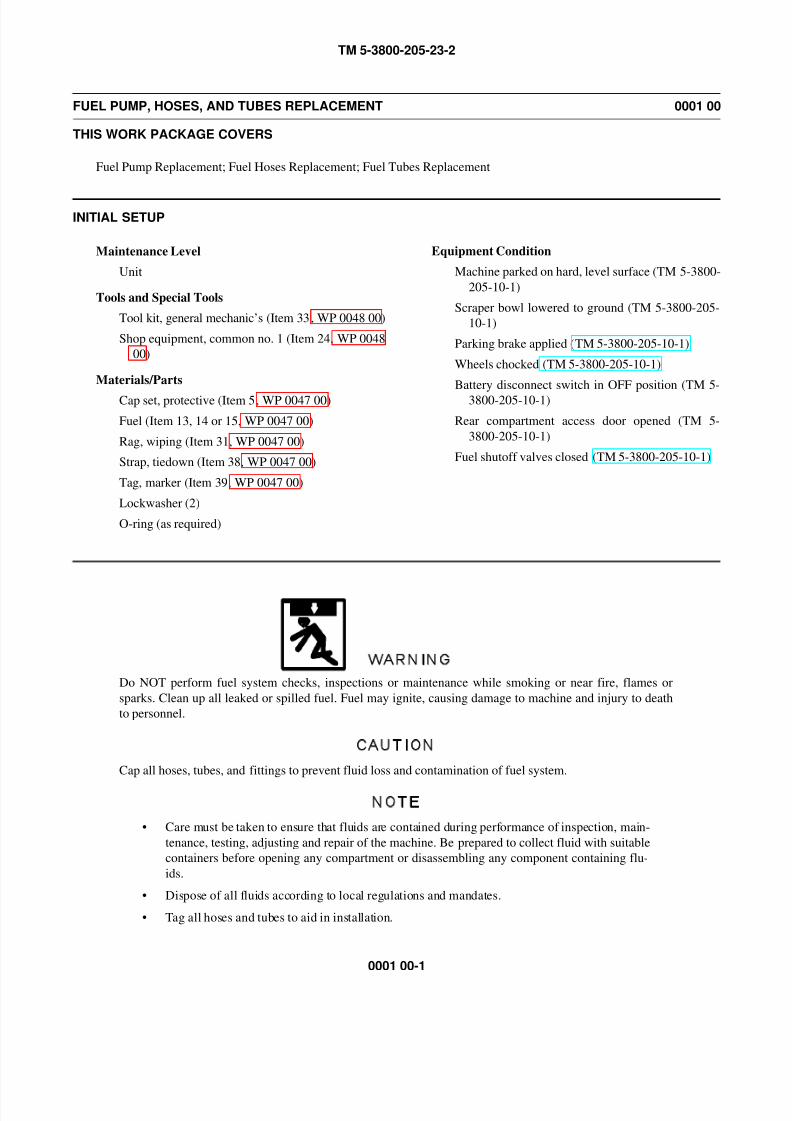
FUEL PUMP, HOSES, AND TUBES REPLACEMENT 0001 00
THIS WORK PACKAGE COVERS
Fuel Pump Replacement; Fuel Hoses Replacement; Fuel Tubes Replacement
INITIAL SETUP
Maintenance Level
Unit
Tools and Special Tools
Tool kit, general mechanic’s (Item 33, WP 0048 00)
Shop equipment, common no. 1 (Item 24, WP 0048
00)
Materials/Parts
Cap set, protective (Item 5, WP 0047 00)
Fuel (Item 13, 14 or 15, WP 0047 00)
Rag, wiping (Item 31, WP 0047 00)
Strap, tiedown (Item 38, WP 0047 00)
Tag, marker (Item 39, WP 0047 00)
Lockwasher (2)
O-ring (as required)
Equipment Condition
Machine parked on hard, level surface (TM 5-3800-
205-10-1)
Scraper bowl lowered to ground (TM 5-3800-205-
10-1)
Parking brake applied (TM 5-3800-205-10-1)
Wheels chocked (TM 5-3800-205-10-1)
Battery disconnect switch in OFF position (TM 5-
3800-205-10-1)
Rear compartment access door opened (TM 5-
3800-205-10-1)
Fuel shutoff valves closed (TM 5-3800-205-10-1)
WARNING
Do NOT perform fuel system checks, inspections or maintenance while smoking or near fire, flames or
sparks. Clean up all leaked or spilled fuel. Fuel may ignite, causing damage to machine and injury to death
to personnel.
CAUTION
Cap all hoses, tubes, and fittings to prevent fluid loss and contamination of fuel system.
NOTE
• Care must be taken to ensure that fluids are contained during performance of inspection, main-
tenance, testing, adjusting and repair of the machine. Be prepared to collect fluid with suitable
containers before opening any compartment or disassembling any component containing flu-
ids.
• Dispose of all fluids according to local regulations and mandates.
• Tag all hoses and tubes to aid in installation.

8/14/2019 TM 5-3800-205-23-2 MODEL 613CS
http://slidepdf.com/reader/full/tm-5-3800-205-23-2-model-613cs 24/276
TM 5-3800-205-23-2
0001 00-2
FUEL PUMP, HOSES, AND TUBES REPLACEMENT - CONTINUED 0001 00
FUEL PUMP REPLACEMENT
CAUTION
Use two wrench method when disconnecting fuel hose and tube from fuel pump. Failure to follow this cau-
tion may result in damage to ceramic adapter.
1. Disconnect hose (6) and tube (2) from fuel pump (5). Remove and discard O-rings.
NOTE
Tag wires to aid in installation.
2. Remove two nuts (3), lockwashers (4), and wires (1)
from fuel pump (5). Discard lockwashers.
NOTE
Note position of fuel pump to aid in installation.
3. Remove screw (8), washer (9), clamp (7), and fuel pump (5) from rear of machine.
4. Remove and inspect fittings from fuel pump (5). Replace fittings if damaged.
5. Lubricate new O-rings with clean fuel and install on fuel pump (5).
6. Install two wires (1) on fuel pump (5) with two new lockwashers (4) and nuts (3).
1
2
3,4
5
6
390-1294

8/14/2019 TM 5-3800-205-23-2 MODEL 613CS
http://slidepdf.com/reader/full/tm-5-3800-205-23-2-model-613cs 25/276
TM 5-3800-205-23-2
0001 00-3
FUEL PUMP, HOSES, AND TUBES REPLACEMENT - CONTINUED 0001 00
FUEL PUMP REPLACEMENT - CONTINUED
NOTE
Arrow marking on fuel pump must point toward front of machine.
7. Position fuel pump (5) on machine and install clamp (7) with washer (9) and screw (8).
CAUTION
Use two wrench method when connecting fuel hose and tube to fuel pump. Failure to follow this caution
may result in damage to ceramic adapter.
8. Connect tube (2) and hose (6) on fuel pump (5).
9. Open fuel shutoff valves (TM 5-3800-205-10-1).
WARNING
If machine is parked indoors, DO NOT run engine unless exhaust fumes are vented to the outside. Failure to
follow this warning may cause injury or death due to carbon monoxide poisoning.
10. Prime fuel system and start engine (TM 5-3800-205-10-1). Check for fuel leaks.
11. Close rear compartment access door (TM 5-3800-205-10-1).
5 7
8,9390-1295
8/14/2019 TM 5-3800-205-23-2 MODEL 613CS
http://slidepdf.com/reader/full/tm-5-3800-205-23-2-model-613cs 26/276
TM 5-3800-205-23-2
0001 00-4
FUEL PUMP, HOSES, AND TUBES REPLACEMENT - CONTINUED 0001 00
FUEL HOSES REPLACEMENT
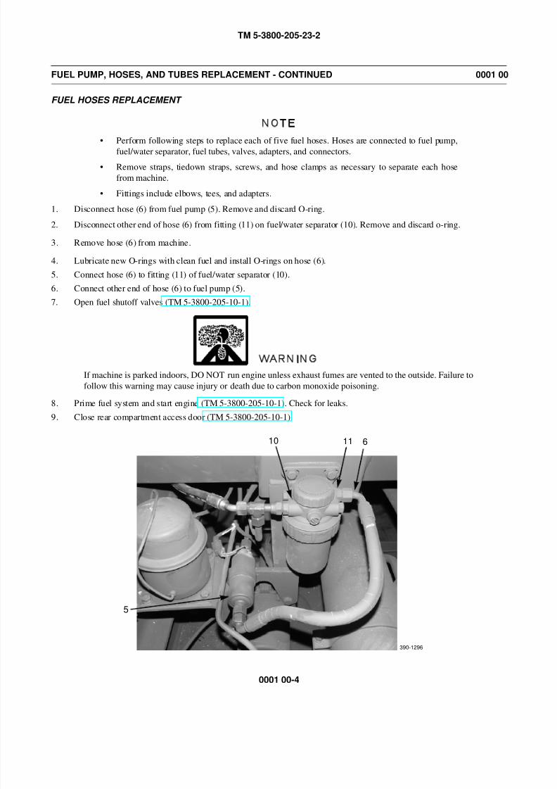
NOTE
• Perform following steps to replace each of five fuel hoses. Hoses are connected to fuel pump,fuel/water separator, fuel tubes, valves, adapters, and connectors.
• Remove straps, tiedown straps, screws, and hose clamps as necessary to separate each hose
from machine.
• Fittings include elbows, tees, and adapters.
1. Disconnect hose (6) from fuel pump (5). Remove and discard O-ring.
2. Disconnect other end of hose (6) from fitting (11) on fuel/water separator (10). Remove and discard o-ring.
3. Remove hose (6) from machine.
4. Lubricate new O-rings with clean fuel and install O-rings on hose (6).
5. Connect hose (6) to fitting (11) of fuel/water separator (10).6. Connect other end of hose (6) to fuel pump (5).
7. Open fuel shutoff valves (TM 5-3800-205-10-1).
WARNING
If machine is parked indoors, DO NOT run engine unless exhaust fumes are vented to the outside. Failure to
follow this warning may cause injury or death due to carbon monoxide poisoning.
8. Prime fuel system and start engine (TM 5-3800-205-10-1). Check for leaks.
9. Close rear compartment access door (TM 5-3800-205-10-1).
10 11 6
5
390-1296

8/14/2019 TM 5-3800-205-23-2 MODEL 613CS
http://slidepdf.com/reader/full/tm-5-3800-205-23-2-model-613cs 27/276
8/14/2019 TM 5-3800-205-23-2 MODEL 613CS
http://slidepdf.com/reader/full/tm-5-3800-205-23-2-model-613cs 28/276
TM 5-3800-205-23-2
0001 00-6
FUEL PUMP, HOSES AND TUBES REPLACEMENT - CONTINUED 0001 00
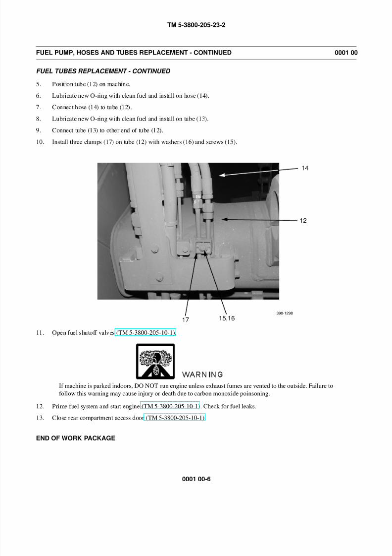
FUEL TUBES REPLACEMENT - CONTINUED
5. Position tube (12) on machine.
6. Lubricate new O-ring with clean fuel and install on hose (14).
7. Connect hose (14) to tube (12).
8. Lubricate new O-ring with clean fuel and install on tube (13).
9. Connect tube (13) to other end of tube (12).
10. Install three clamps (17) on tube (12) with washers (16) and screws (15).
11. Open fuel shutoff valves (TM 5-3800-205-10-1).
WARNING
If machine is parked indoors, DO NOT run engine unless exhaust fumes are vented to the outside. Failure to
follow this warning may cause injury or death due to carbon monoxide poinsoning.
12. Prime fuel system and start engine (TM 5-3800-205-10-1). Check for fuel leaks.
13. Close rear compartment access door (TM 5-3800-205-10-1).
END OF WORK PACKAGE
14
12
15,16390-1298
17
8/14/2019 TM 5-3800-205-23-2 MODEL 613CS
http://slidepdf.com/reader/full/tm-5-3800-205-23-2-model-613cs 29/276
TM 5-3800-205-23-2
0002 00-1
FUEL/WATER SEPARATOR REPLACEMENT 0002 00
THIS WORK PACKAGE COVERS
Removal, Installation
INITIAL SETUP
Maintenance Level
Unit
Tools and Special Tools
Tool kit, general mechanic’s (Item 33, WP 0048 00)
Shop equipment, common no. 1 (Item 24, WP 0048
00)
Materials/Parts
Cap set, protective (Item 5, WP 0047 00)
Fuel (Item 13, 14 or 15, WP 0047 00)
Rag, wiping (Item 31, WP 0047 00)
Filter element, fluid
O-ring (6)
Equipment Condition
Machine parked on hard, level surface (TM 5-3800-
205-10-1)
Scraper bowl lowered to ground (TM 5-3800-205-
10-1)
Parking brake applied (TM 5-3800-205-10-1)
Wheel chocked (TM 5-3800-205-10-1)
Battery disconnect switch in OFF position (TM 5-
3800-205-10-1)
Rear compartment access door opened (TM 5-
3800-205-10-1)
Fuel shutoff valves closed (TM 5-3800-205-10-1)
Fuel/water separator drained (TM 5-3800-205-10-
1)
WARNING
DO NOT perform fuel system checks, inspections or maintenance while smoking or near fire, flames or
sparks. Clean up all leaked or spilled fuel. Fuel may ignite, causing damage to machine and injury or death
to personnel.
CAUTION
Cap all hoses and fittings to prevent fluid loss and contmination of fuel system.
NOTE
• Care must be taken to ensure that fluids are contained during performance of inspection, main-
tenance, testing, adjusting and repair of the machine. Be prepared to collect fluid with suitable
containers before opening any compartment or disassembling any component containing flu-
ids.
• Dispose of all fluids according to local regulations and mandates.
8/14/2019 TM 5-3800-205-23-2 MODEL 613CS
http://slidepdf.com/reader/full/tm-5-3800-205-23-2-model-613cs 30/276
TM 5-3800-205-23-2
0002 00-2
FUEL/WATER SEPARATOR REPLACEMENT - CONTINUED 0002 00
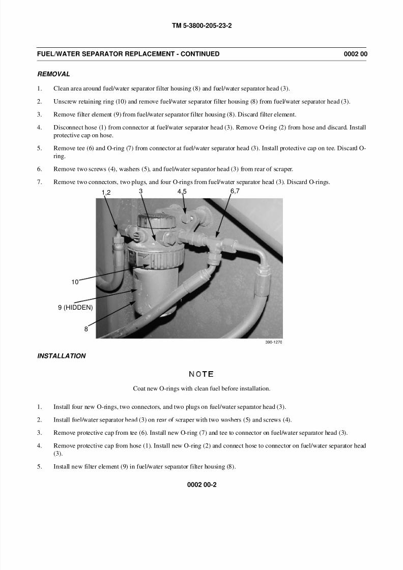
REMOVAL
1. Clean area around fuel/water separator filter housing (8) and fuel/water separator head (3).
2. Unscrew retaining ring (10) and remove fuel/water separator filter housing (8) from fuel/water separator head (3).
3. Remove filter element (9) from fuel/water separator filter housing (8). Discard filter element.
4. Disconnect hose (1) from connector at fuel/water separator head (3). Remove O-ring (2) from hose and discard. Install
protective cap on hose.
5. Remove tee (6) and O-ring (7) from connector at fuel/water separator head (3). Install protective cap on tee. Discard O-
ring.
6. Remove two screws (4), washers (5), and fuel/water separator head (3) from rear of scraper.
7. Remove two connectors, two plugs, and four O-rings from fuel/water separator head (3). Discard O-rings.
INSTALLATION
NOTE
Coat new O-rings with clean fuel before installation.
1. Install four new O-rings, two connectors, and two plugs on fuel/water separator head (3).
2. Install fuel/water separator head (3) on rear of scraper with two washers (5) and screws (4).
3. Remove protective cap from tee (6). Install new O-ring (7) and tee to connector on fuel/water separator head (3).
4. Remove protective cap from hose (1). Install new O-ring (2) and connect hose to connector on fuel/water separator head
(3).
5. Install new filter element (9) in fuel/water separator filter housing (8).
1,2 3 4,5 6,7
390-1270
10
8
9 (HIDDEN)
8/14/2019 TM 5-3800-205-23-2 MODEL 613CS
http://slidepdf.com/reader/full/tm-5-3800-205-23-2-model-613cs 31/276
TM 5-3800-205-23-2
0002 00-3
FUEL/WATER SEPARATOR REPLACEMENT - CONTINUED 0002 00
INSTALLATION - CONTINUED
NOTE
• Ensure fuel/water separator head is clean before installing fuel/water separator filter housing tohead.
• Fuel filter has a locating notch that only allows proper installation.
6. Install fuel/water separator filter housing (8) on fuel/water separator head (3). Tighten retaining ring (10).
7. Open fuel shutoff valves (TM 5-3800-205-10-1).
WARNING
If machine is parked indoors, DO NOT run engine unless exhaust fumes are vented to the outside. Failure to
follow this warning may cause injury or death due to carbon monoxide poisoning.
8. Prime fuel system and start engine (TM 5-3800-205-10-1). Check for fuel leaks.
9. Close rear compartment access door (TM 5-3800-205-10-1).
END OF WORK PACKAGE

8/14/2019 TM 5-3800-205-23-2 MODEL 613CS
http://slidepdf.com/reader/full/tm-5-3800-205-23-2-model-613cs 32/276
TM 5-3800-205-23-2
0002 00-4
This Page Intentionally Left Blank.
8/14/2019 TM 5-3800-205-23-2 MODEL 613CS
http://slidepdf.com/reader/full/tm-5-3800-205-23-2-model-613cs 33/276
TM 5-3800-205-23-2
0003 00-1
ELECTRICAL GENERAL MAINTENANCE INSTRUCTIONS 0003 00
THIS WORK PACKAGE COVERS
Multiple-Pin Connector Identification Diagrams
Connector Repair
Sealed Connector Repair
Receptacle Connector Repair
Waterproof Connector Repair
Military Connector Repair
Ring Terminal Repair
Splicing Wires
Electrical Ground Points
Multimeter Usage
Relay Inspection and Test
Wiring Harness Replacement
INITIAL SETUP
Maintenance Level
Unit
Tools and Special Tools
Tool kit, general mechanic’s (Item 33, WP 0048 00)
Shop equipment, common no. 1 (Item 24, WP 0048
00)
Heater gun, gun type, electric (Item 14, WP 0048
00)
Materials/Parts
Cloth, abrasive (Item 7, WP 0047 00)
Detergent (Item 11, WP 0047 00)
Grease, electrically conductive (Item 17, WP 0047
00)
Insulating varnish, electrical (Item 19, WP 0047 00)
Insulating sleeving, electrical (Item 20, WP 0047
00)
Tag, marker (Item 39, WP 0047 00)
NOTE
• Use electrically conductive grease on unprotected (exposed to weather) electrical connectors
before connections are made.
• Use electrical insulating varnish on all electrical connections that are mounted outside of
machine and are exposed to harsh weather and/or road spray.

8/14/2019 TM 5-3800-205-23-2 MODEL 613CS
http://slidepdf.com/reader/full/tm-5-3800-205-23-2-model-613cs 34/276
TM 5-3800-205-23-2
0003 00-2
ELECTRICAL GENERAL MAINTENANCE INSTRUCTIONS - CONTINUED 0003 00
MULTIPLE-PIN CONNECTOR IDENTIFICATION DIAGRAMS
NOTE
The following diagrams illustrate typical multiple-pin connectors and identify pin numbers as viewed fromwire side of connector.
390-1189
390-1048
390-1049
390-1190
8/14/2019 TM 5-3800-205-23-2 MODEL 613CS
http://slidepdf.com/reader/full/tm-5-3800-205-23-2-model-613cs 35/276
TM 5-3800-205-23-2
0003 00-3
ELECTRICAL GENERAL MAINTENANCE INSTRUCTIONS - CONTINUED 0003 00
CONNECTOR REPAIR
NOTE
• Perform the following steps for each wire of connector.
• Tag wires to aid in installation.
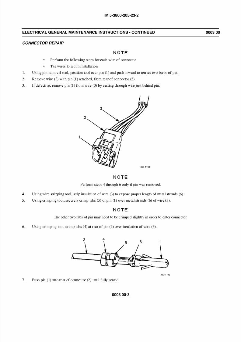
1. Using pin removal tool, position tool over pin (1) and push inward to retract two barbs of pin.
2. Remove wire (3) with pin (1) attached, from rear of connector (2).
3. If defective, remove pin (1) from wire (3) by cutting through wire just behind pin.
NOTE
Perform steps 4 through 6 only if pin was removed.
4. Using wire stripping tool, strip insulation of wire (3) to expose proper length of metal strands (6).
5. Using crimping tool, securely crimp tabs (5) of pin (1) over metal strands (6) of wire (3).
NOTE
The other two tabs of pin may need to be crimped slightly in order to enter connector.
6. Using crimping tool, crimp tabs (4) at rear of pin (1) over insulation of wire (3).
7. Push pin (1) into rear of connector (2) until fully seated.
1
2
3
390-1191
3 4 5 6 1
390-1192
8/14/2019 TM 5-3800-205-23-2 MODEL 613CS
http://slidepdf.com/reader/full/tm-5-3800-205-23-2-model-613cs 36/276
TM 5-3800-205-23-2
0003 00-4
ELECTRICAL GENERAL MAINTENANCE INSTRUCTIONS - CONTINUED 0003 00
SEALED CONNECTOR REPAIR
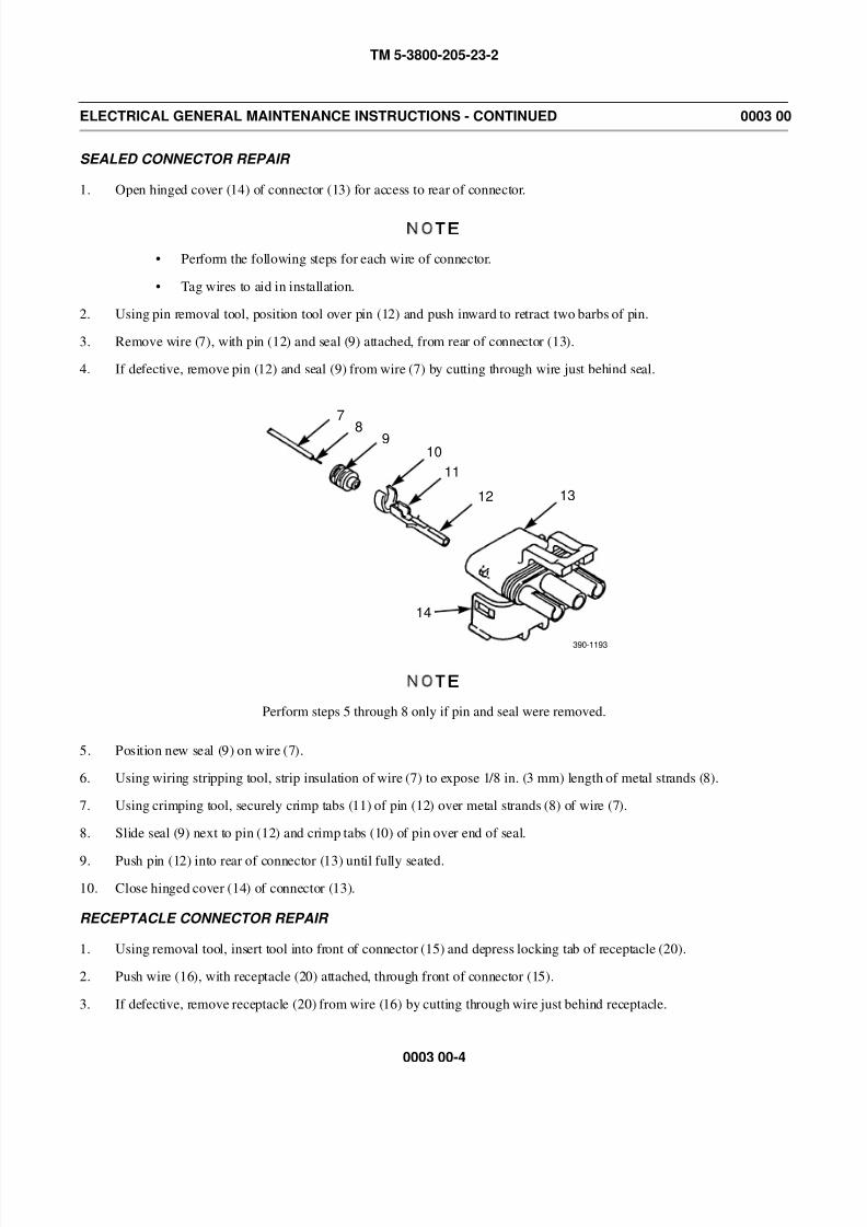
1. Open hinged cover (14) of connector (13) for access to rear of connector.
NOTE
• Perform the following steps for each wire of connector.
• Tag wires to aid in installation.
2. Using pin removal tool, position tool over pin (12) and push inward to retract two barbs of pin.
3. Remove wire (7), with pin (12) and seal (9) attached, from rear of connector (13).
4. If defective, remove pin (12) and seal (9) from wire (7) by cutting through wire just behind seal.
NOTE
Perform steps 5 through 8 only if pin and seal were removed.
5. Position new seal (9) on wire (7).
6. Using wiring stripping tool, strip insulation of wire (7) to expose 1/8 in. (3 mm) length of metal strands (8).
7. Using crimping tool, securely crimp tabs (11) of pin (12) over metal strands (8) of wire (7).
8. Slide seal (9) next to pin (12) and crimp tabs (10) of pin over end of seal.
9. Push pin (12) into rear of connector (13) until fully seated.
10. Close hinged cover (14) of connector (13).
RECEPTACLE CONNECTOR REPAIR
1. Using removal tool, insert tool into front of connector (15) and depress locking tab of receptacle (20).
2. Push wire (16), with receptacle (20) attached, through front of connector (15).
3. If defective, remove receptacle (20) from wire (16) by cutting through wire just behind receptacle.
7
9
12 13
14
810
11
390-1193
8/14/2019 TM 5-3800-205-23-2 MODEL 613CS
http://slidepdf.com/reader/full/tm-5-3800-205-23-2-model-613cs 37/276
TM 5-3800-205-23-2
0003 00-5
ELECTRICAL GENERAL MAINTENANCE INSTRUCTIONS - CONTINUED 0003 00
RECEPTACLE CONNECTOR REPAIR - CONTINUED
NOTE
Perform steps 4 through 7 only if receptacle was removed.
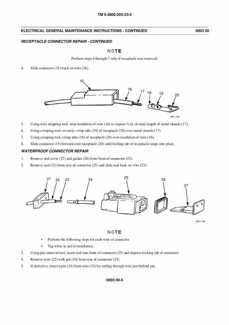
4. Slide connector (15) back on wire (16).
5. Using wire stripping tool, strip insulation of wire (16) to expose in. (6 mm) length of metal strands (17).
6. Using crimping tool, securely crimp tabs (19) of receptacle (20) over metal strands (17).
7. Using crimping tool, crimp tabs (18) of receptacle (20) over insulation of wire (16).
8. Slide connector (15) forward over receptacle (20) until locking tab of receptacle snaps into place.
WATERPROOF CONNECTOR REPAIR
1. Remove end cover (27) and gasket (26) from front of connector (25).
2. Remove seal (21) from rear of connector (25) and slide seal back on wire (22).
NOTE
• Perform the following steps for each wire of connector.
• Tag wires to aid in installation.
3. Using pin removal tool, insert tool into front of connector (25) and depress locking tab of connector.
4. Remove wire (22) with pin (24) from rear of connector (25).
5. If defective, remove pin (24) from wire (22) by cutting through wire just behind pin.
15
1617 18 19 20
390-1194
21 22 23 2425
26
27
390-1195
8/14/2019 TM 5-3800-205-23-2 MODEL 613CS
http://slidepdf.com/reader/full/tm-5-3800-205-23-2-model-613cs 38/276
TM 5-3800-205-23-2
0003 00-6
ELECTRICAL GENERAL MAINTENANCE INSTRUCTIONS - CONTINUED 0003 00
WATERPROOF CONNECTOR REPAIR - CONTINUED
NOTE
Perform steps 6 through 9 only if pin was removed.
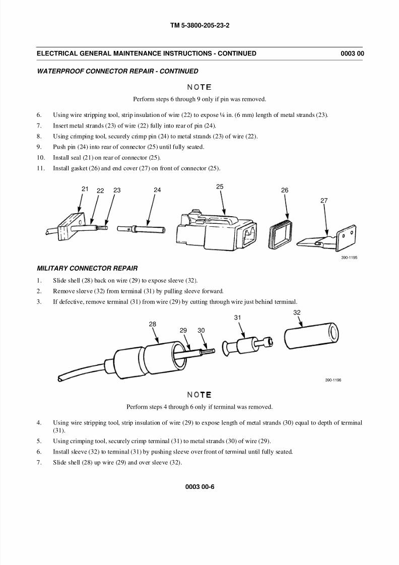
6. Using wire stripping tool, strip insulation of wire (22) to expose in. (6 mm) length of metal strands (23).
7. Insert metal strands (23) of wire (22) fully into rear of pin (24).
8. Using crimping tool, securely crimp pin (24) to metal strands (23) of wire (22).
9. Push pin (24) into rear of connector (25) until fully seated.
10. Install seal (21) on rear of connector (25).
11. Install gasket (26) and end cover (27) on front of connector (25).
MILITARY CONNECTOR REPAIR
1. Slide shell (28) back on wire (29) to expose sleeve (32).
2. Remove sleeve (32) from terminal (31) by pulling sleeve forward.
3. If defective, remove terminal (31) from wire (29) by cutting through wire just behind terminal.
NOTEPerform steps 4 through 6 only if terminal was removed.
4. Using wire stripping tool, strip insulation of wire (29) to expose length of metal strands (30) equal to depth of terminal
(31).
5. Using crimping tool, securely crimp terminal (31) to metal strands (30) of wire (29).
6. Install sleeve (32) to terminal (31) by pushing sleeve over front of terminal until fully seated.
7. Slide shell (28) up wire (29) and over sleeve (32).
21 22 23 2425
26
27
390-1195
2829 30
3132
390-1196
8/14/2019 TM 5-3800-205-23-2 MODEL 613CS
http://slidepdf.com/reader/full/tm-5-3800-205-23-2-model-613cs 39/276
TM 5-3800-205-23-2
0003 00-7
ELECTRICAL GENERAL MAINTENANCE INSTRUCTIONS - CONTINUED 0003 00
RING TERMINAL REPAIR
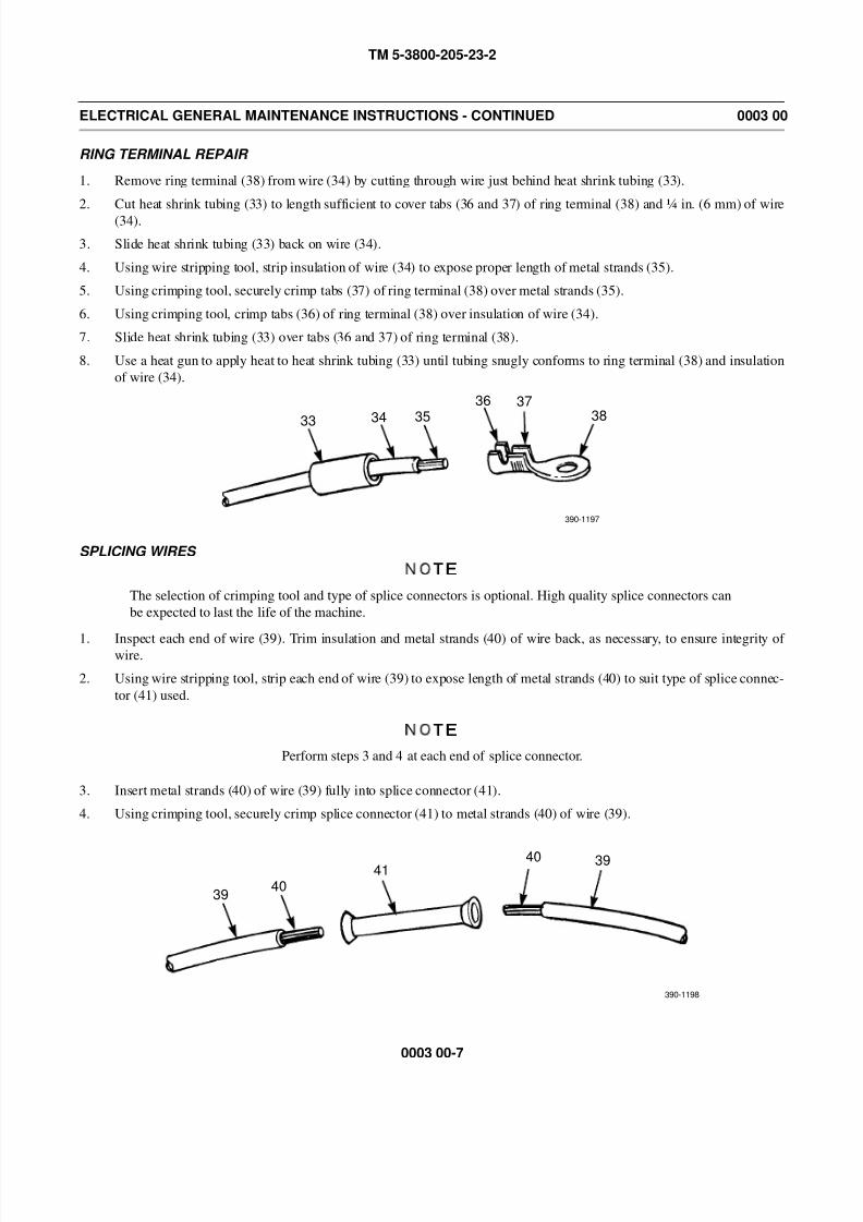
1. Remove ring terminal (38) from wire (34) by cutting through wire just behind heat shrink tubing (33).
2. Cut heat shrink tubing (33) to length sufficient to cover tabs (36 and 37) of ring terminal (38) and in. (6 mm) of wire
(34).
3. Slide heat shrink tubing (33) back on wire (34).
4. Using wire stripping tool, strip insulation of wire (34) to expose proper length of metal strands (35).
5. Using crimping tool, securely crimp tabs (37) of ring terminal (38) over metal strands (35).
6. Using crimping tool, crimp tabs (36) of ring terminal (38) over insulation of wire (34).
7. Slide heat shrink tubing (33) over tabs (36 and 37) of ring terminal (38).
8. Use a heat gun to apply heat to heat shrink tubing (33) until tubing snugly conforms to ring terminal (38) and insulation
of wire (34).
SPLICING WIRES
NOTE
The selection of crimping tool and type of splice connectors is optional. High quality splice connectors can
be expected to last the life of the machine.
1. Inspect each end of wire (39). Trim insulation and metal strands (40) of wire back, as necessary, to ensure integrity of wire.
2. Using wire stripping tool, strip each end of wire (39) to expose length of metal strands (40) to suit type of splice connec-
tor (41) used.
NOTE
Perform steps 3 and 4 at each end of splice connector.
3. Insert metal strands (40) of wire (39) fully into splice connector (41).
4. Using crimping tool, securely crimp splice connector (41) to metal strands (40) of wire (39).
3334 35
36 3738
390-1197
3940
4140 39
390-1198
8/14/2019 TM 5-3800-205-23-2 MODEL 613CS
http://slidepdf.com/reader/full/tm-5-3800-205-23-2-model-613cs 40/276
TM 5-3800-205-23-2
0003 00-8
ELECTRICAL GENERAL MAINTENANCE INSTRUCTIONS - CONTINUED 0003 00
ELECTRICAL GROUND POINTS
Many electrical problems are the result of poor ground connections. Ensure that ground connections are good by per-
forming the following steps:
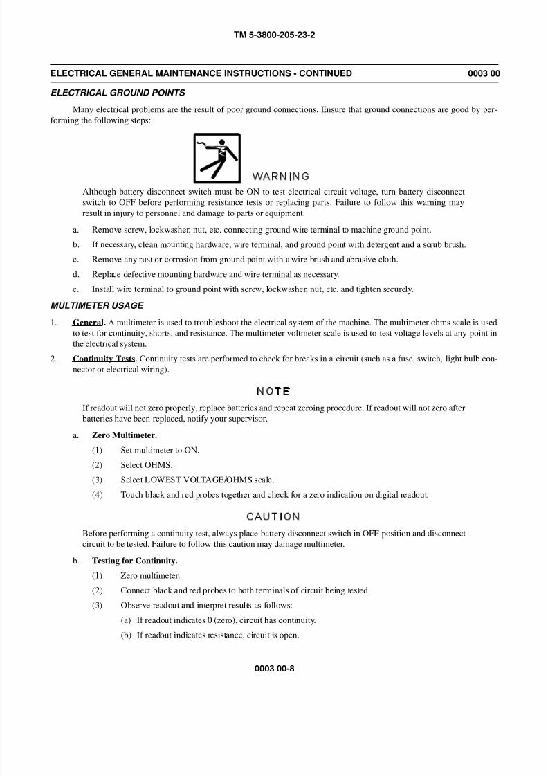
WARNING
Although battery disconnect switch must be ON to test electrical circuit voltage, turn battery disconnect
switch to OFF before performing resistance tests or replacing parts. Failure to follow this warning may
result in injury to personnel and damage to parts or equipment.
a. Remove screw, lockwasher, nut, etc. connecting ground wire terminal to machine ground point.
b. If necessary, clean mounting hardware, wire terminal, and ground point with detergent and a scrub brush.
c. Remove any rust or corrosion from ground point with a wire brush and abrasive cloth.
d. Replace defective mounting hardware and wire terminal as necessary.
e. Install wire terminal to ground point with screw, lockwasher, nut, etc. and tighten securely.
MULTIMETER USAGE
1. General. A multimeter is used to troubleshoot the electrical system of the machine. The multimeter ohms scale is used
to test for continuity, shorts, and resistance. The multimeter voltmeter scale is used to test voltage levels at any point in
the electrical system.
2. Continuity Tests. Continuity tests are performed to check for breaks in a circuit (such as a fuse, switch, light bulb con-
nector or electrical wiring).
NOTE
If readout will not zero properly, replace batteries and repeat zeroing procedure. If readout will not zero afterbatteries have been replaced, notify your supervisor.
a. Zero Multimeter.
(1) Set multimeter to ON.
(2) Select OHMS.
(3) Select LOWEST VOLTAGE/OHMS scale.
(4) Touch black and red probes together and check for a zero indication on digital readout.
CAUTION
Before performing a continuity test, always place battery disconnect switch in OFF position and disconnect
circuit to be tested. Failure to follow this caution may damage multimeter.
b. Testing for Continuity.
(1) Zero multimeter.
(2) Connect black and red probes to both terminals of circuit being tested.
(3) Observe readout and interpret results as follows:
(a) If readout indicates 0 (zero), circuit has continuity.
(b) If readout indicates resistance, circuit is open.

8/14/2019 TM 5-3800-205-23-2 MODEL 613CS
http://slidepdf.com/reader/full/tm-5-3800-205-23-2-model-613cs 41/276
TM 5-3800-205-23-2
0003 00-9
ELECTRICAL GENERAL MAINTENANCE INSTRUCTIONS - CONTINUED 0003 00
MULTIMETER USAGE - CONTINUED
CAUTION
Before performing a continuity test, always place battery disconnect switch in OFF position and disconnect
circuit to be tested. Failure to follow this caution may damage multimeter.
c. Testing for Shorts. A short (or short circuit) occurs when two circuits that should not be connected have metal-to-
metal contact with each other. A short also occurs when a circuit that should not touch ground has metal-to-metal
contact with ground.
(1) Zero multimeter.
(2) Connect black probe to one pin and red probe to either ground or another pin.
(3) Observe readout and interpret results as follows:
(a) If readout indicates 0 (zero), circuits are shorted or circuit is grounded, if testing to ground.
(b) If readout does not indicate 0 (zero), circuits are not shorted.
(c) If readout jumps or flickers, circuits are shorted or grounded intermittently.
CAUTION
Before performing a continuity test, always place battery disconnect switch in OFF position and disconnect
circuit to be tested. Failure to follow this caution may damage multimeter.
d. Testing for Resistance. Allowable resistance readings depend on circuit being tested. Refer to the particular sec-
tion dealing with that circuit or component for allowable readings.
(1) Zero multimeter.
(2) Select OHMS.
(3) Select LOWEST VOLTAGE/OHMS range. If test specifies ohms range, select required range.
(4) Connect black and red probes across circuit to be tested.
(5) Observe readout and interpret results as circuit resistance.
3. Measuring DC Voltage.
a. Set multimeter to ON.
b. Select VOLTS.
c. Select volts DC.
d. Select LOWEST VOLTAGE/OHMS range for voltage range that is higher than volts to be measured.
e. Connect red probe to positive (+) pin and black probe to negative (-) pin.
f. Observe readout and interpret results as DC voltage in circuit being tested.

8/14/2019 TM 5-3800-205-23-2 MODEL 613CS
http://slidepdf.com/reader/full/tm-5-3800-205-23-2-model-613cs 42/276
TM 5-3800-205-23-2
0003 00-10
ELECTRICAL GENERAL MAINTENANCE INSTRUCTIONS - CONTINUED 0003 00
RELAY INSPECTION AND TEST
1. Inspecting Relays.
a. Check for bent or damaged pins.
b. Check for burned or damaged relay case.
2. Testing Relays.
NOTE
When testing relays, always refer to the circuit diagram printed or stamped on relay case.
a. Using a multimeter, check for continuity across relay coil.
b. Using a multimeter, check open or closed contacts within relay.
WIRING HARNESS REPLACEMENT
NOTE
• Wiring harnesses are composed of multiple wires enclosed in a protective wire loom with one or more
connectors of varying configurations at each end. When damaged, wiring harnesses can be repaired by
replacing connectors or by splicing wires. If damage is extensive, entire wiring harness should be
replaced.
• Perform the following steps to replace a typical wiring harness. Refer to electrical schematics in fold-
outs at back of manual for assistance.
• Tag wire leads and connectors to aid in installation.
1. Provide access to wiring harness, as necessary, by removing components.
2. Place battery disconnect switch in OFF position.
3. Remove mounting hardware (nut, locknut, lockwasher, screw, etc.) or disconnect connector(s) of wiring harness to dis-connect wiring harness from electrical component at one end of wiring harness.
4. Trace length of wiring harness and remove tie straps and clamps, as necessary. Discard tiedown straps.
5. Repeat step 3 at other end of wiring harness.
6. Remove wiring harness from machine.
NOTE
Ensure wire loom is installed over wiring harness as required prior to installation.
7. Position wiring harness to machine.
8. Connect connector(s) of wiring harness or install mounting hardware (nut, locknut, lockwasher, screw etc.) to connect
wiring harness to electrical component at one end of wiring harness.
9. Repeat step 8 at other end of wiring harness.
10. Install clamps and new tie straps along length of wiring harness.
11. Place battery disconnect switch in ON position.
12. Install components, as necessary.
END OF WORK PACKAGE
8/14/2019 TM 5-3800-205-23-2 MODEL 613CS
http://slidepdf.com/reader/full/tm-5-3800-205-23-2-model-613cs 43/276
TM 5-3800-205-23-2
0004 00-1
GROUND STRAPS REPLACEMENT 0004 00
THIS WORK PACKAGE COVERS
Air Intake Heater-To-Engine Ground Strap Replacement, Starter Ground Cable Replacement, Cab-To-Frame Ground
Strap Replacement
INITIAL SETUP
Maintenance Level
Unit
Tools and Special Tools
Tool kit, general mechanic’s (Item 33, WP 0048 00)
Shop equipment, common no. 1 (Item 24, WP 0048
00)
Materials/Parts
Lockwasher
Equipment Conditions
Machine parked on hard, level surface (TM 5-3800-
205-10-1)
Scraper bowl lowered to ground (TM 5-3800-204-
10-1)
Parking brake engaged (TM 5-3800-205-10-1)
Wheels chocked (TM 5-3800-205-10-1)
Battery disconnect switch in OFF position (TM 5-
3800-205-10-1)
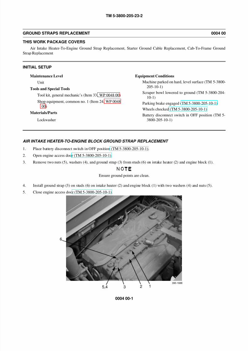
AIR INTAKE HEATER-TO-ENGINE BLOCK GROUND STRAP REPLACEMENT
1. Place battery disconnect switch in OFF position (TM 5-3800-205-10-1).
2. Open engine access door (TM 5-3800-205-10-1).
3. Remove two nuts (5), washers (4), and ground strap (3) from studs (6) on intake heater (2) and engine block (1).
NOTE
Ensure ground points are clean.
4. Install ground strap (3) on studs (6) on intake heater (2) and engine block (1) with two washers (4) and nuts (5).
5. Close engine access door (TM 5-3800-205-10-1).
6
1235,4390-1688
8/14/2019 TM 5-3800-205-23-2 MODEL 613CS
http://slidepdf.com/reader/full/tm-5-3800-205-23-2-model-613cs 44/276
TM 5-3800-205-23-2
0004 00-2
GROUND STRAPS REPLACEMENT - CONTINUED 0004 00
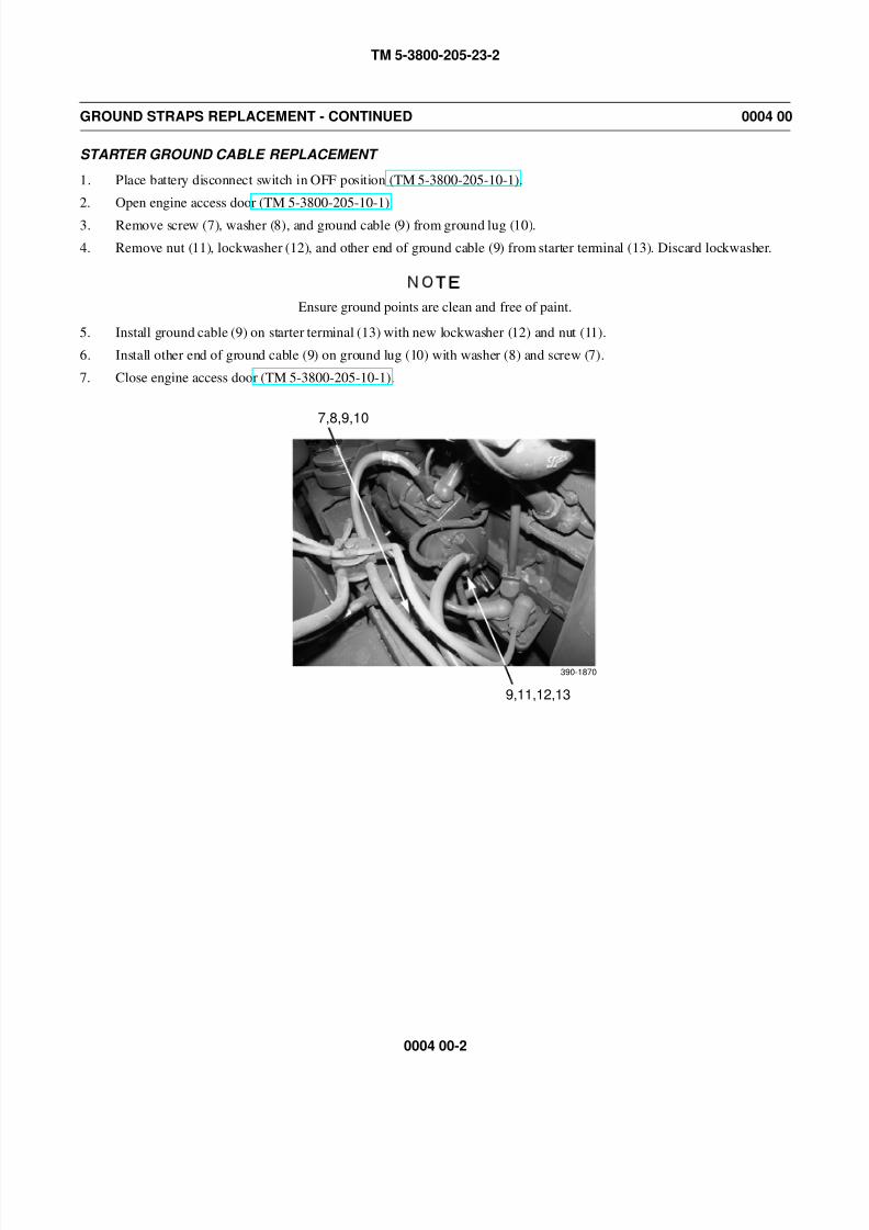
STARTER GROUND CABLE REPLACEMENT
1. Place battery disconnect switch in OFF position (TM 5-3800-205-10-1).
2. Open engine access door (TM 5-3800-205-10-1).
3. Remove screw (7), washer (8), and ground cable (9) from ground lug (10).
4. Remove nut (11), lockwasher (12), and other end of ground cable (9) from starter terminal (13). Discard lockwasher.
NOTE
Ensure ground points are clean and free of paint.
5. Install ground cable (9) on starter terminal (13) with new lockwasher (12) and nut (11).
6. Install other end of ground cable (9) on ground lug (10) with washer (8) and screw (7).
7. Close engine access door (TM 5-3800-205-10-1).
7,8,9,10
9,11,12,13
390-1870
8/14/2019 TM 5-3800-205-23-2 MODEL 613CS
http://slidepdf.com/reader/full/tm-5-3800-205-23-2-model-613cs 45/276
TM 5-3800-205-23-2
0004 00-3
GROUND STRAPS REPLACEMENT - CONTINUED 0004 00
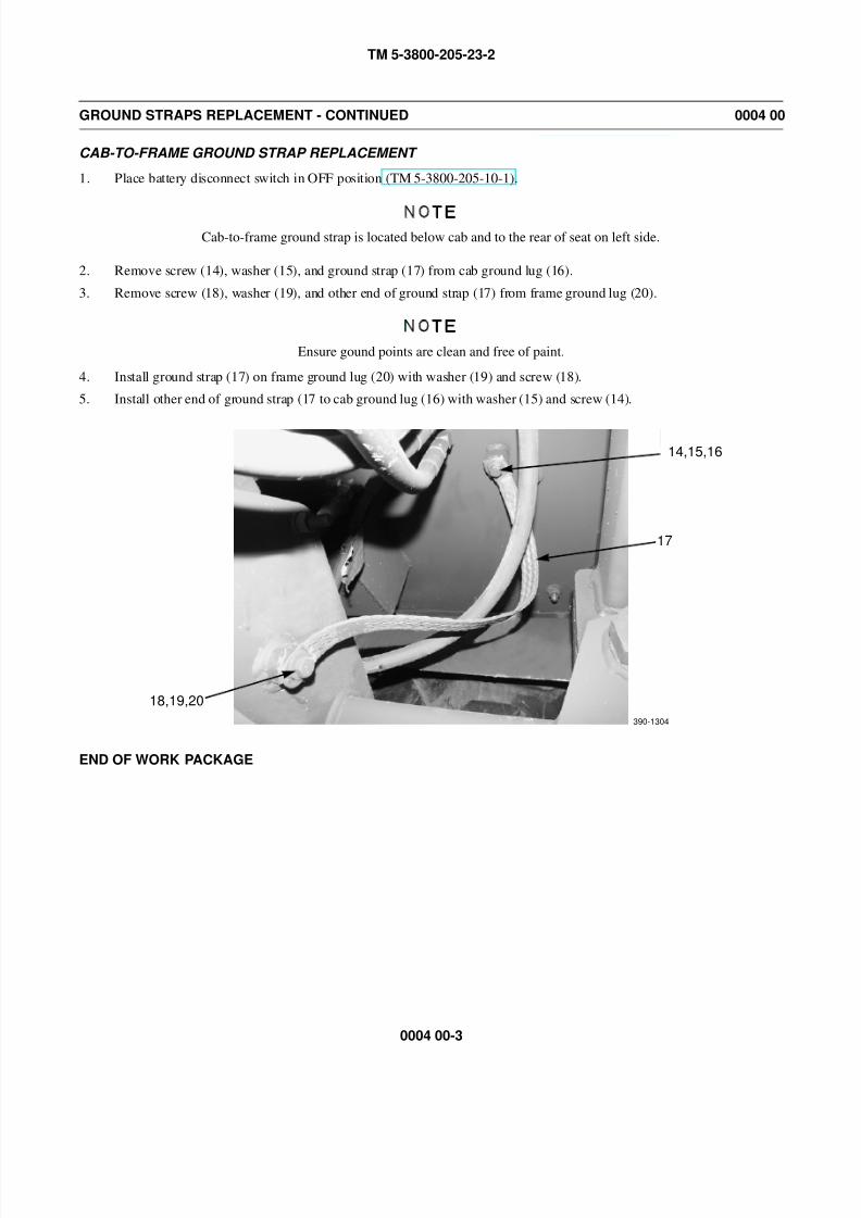
CAB-TO-FRAME GROUND STRAP REPLACEMENT
1. Place battery disconnect switch in OFF position (TM 5-3800-205-10-1).
NOTE
Cab-to-frame ground strap is located below cab and to the rear of seat on left side.
2. Remove screw (14), washer (15), and ground strap (17) from cab ground lug (16).
3. Remove screw (18), washer (19), and other end of ground strap (17) from frame ground lug (20).
NOTE
Ensure gound points are clean and free of paint.
4. Install ground strap (17) on frame ground lug (20) with washer (19) and screw (18).
5. Install other end of ground strap (17 to cab ground lug (16) with washer (15) and screw (14).
END OF WORK PACKAGE
14,15,16
17
18,19,20
390-1304

8/14/2019 TM 5-3800-205-23-2 MODEL 613CS
http://slidepdf.com/reader/full/tm-5-3800-205-23-2-model-613cs 46/276
TM 5-3800-205-23-2
0004 00-4
This Page Intentionally Left Blank.
8/14/2019 TM 5-3800-205-23-2 MODEL 613CS
http://slidepdf.com/reader/full/tm-5-3800-205-23-2-model-613cs 47/276
TM 5-3800-205-23-2
0005 00-1
COMPOSITE LIGHT MAINTENANCE 0005 00
THIS WORK PACKAGE COVERS
Lamp: Removal, Installation
Light Assembly: Removal, Installation
INITIAL SETUP
Maintenance Level
Unit
Tools and Special Tools
Tool kit, general mechanic’s (Item 33, WP 0048 00)
Equipment Condition
Machine parked on hard, level surface (TM 5-3800-205-10-1)
Equipment Condition - Continued
Scraper bowl lowered to ground (TM 5-3800-205-
10-1)
Parking brake applied (TM 5-3800-205-10-1)
Wheels chocked (TM 5-3800-205-10-1)
Battery disconnect switch in OFF position (TM 5-3800-205-10-1)
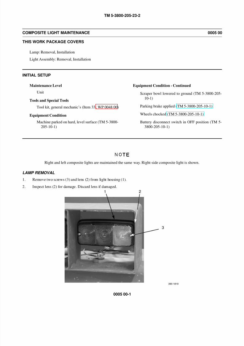
NOTE
Right and left composite lights are maintained the same way. Right-side composite light is shown.
LAMP REMOVAL
1. Remove two screws (3) and lens (2) from light housing (1).
2. Inspect lens (2) for damage. Discard lens if damaged.
1 2
3
390-1819
8/14/2019 TM 5-3800-205-23-2 MODEL 613CS
http://slidepdf.com/reader/full/tm-5-3800-205-23-2-model-613cs 48/276
TM 5-3800-205-23-2
0005 00-2
COMPOSITE LIGHT MAINTENANCE - CONTINUED 0005 00
LAMP REMOVAL - CONTINUED
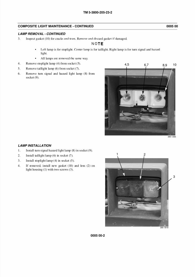
3. Inspect gasket (10) for cracks and tears. Remove and discard gasket if damaged.
NOTE
• Left lamp is for stoplight. Center lamp is for taillight. Right lamp is for turn signal and hazardlight.
• All lamps are removed the same way.
4. Remove stoplight lamp (4) from socket (5).
5. Remove taillight lamp (6) from socket (7).
6. Remove turn signal and hazard light lamp (8) from
socket (9).
LAMP INSTALLATION 1. Install turn signal hazard light lamp (8) in socket (9).
2. Install taillight lamp (6) in socket (7).
3. Install stoplight lamp (4) in socket (5).
4. If removed, install new gasket (10) and lens (2) on
light housing (1) with two screws (3).
4,5 6,7 8,9 10
390-1356
1 2
3
390-1819
8/14/2019 TM 5-3800-205-23-2 MODEL 613CS
http://slidepdf.com/reader/full/tm-5-3800-205-23-2-model-613cs 49/276
TM 5-3800-205-23-2
0005 00-3
COMPOSITE LIGHT MAINTENANCE - CONTINUED 0005 00
LIGHT ASSEMBLY REMOVAL
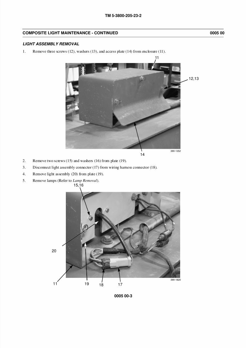
1. Remove three screws (12), washers (13), and access plate (14) from enclosure (11).
2. Remove two screws (15) and washers (16) from plate (19).
3. Disconnect light assembly connector (17) from wiring harness connector (18).
4. Remove light assembly (20) from plate (19).
5. Remove lamps (Refer to Lamp Removal).
12,13
11
14390-1352
15,16
390-1820
17181911
20
8/14/2019 TM 5-3800-205-23-2 MODEL 613CS
http://slidepdf.com/reader/full/tm-5-3800-205-23-2-model-613cs 50/276
TM 5-3800-205-23-2
0005 00-4
COMPOSITE LIGHT MAINTENANCE - CONTINUED 0005 00
LIGHT ASSEMBLY INSTALLATION
1. Install lamps (Refer to Lamp Installation).
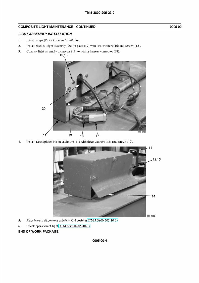
2. Install blackout light assembly (20) on plate (19) with two washers (16) and screws (15).
3. Connect light assembly connector (17) to wiring harness connector (18).
4. Install access plate (14) on enclosure (11) with three washers (13) and screws (12).
5. Place battery disconnect switch in ON position (TM 5-3800-205-10-1).
6. Check operation of lights (TM 5-3800-205-10-1).
END OF WORK PACKAGE
15,16
390-1820
17181911
20
12,13
11
14
390-1352
8/14/2019 TM 5-3800-205-23-2 MODEL 613CS
http://slidepdf.com/reader/full/tm-5-3800-205-23-2-model-613cs 51/276
TM 5-3800-205-23-2
0006 00-1
BLACKOUT LIGHT MAINTENANCE 0006 00
THIS WORK PACKAGE COVERS
LED: Removal, Installation
Light Assembly: Removal, Installation
INITIAL SETUP
Maintenance Level
Unit
Tools and Special Tools
Tool kit, general mechanic’s (Item 33, WP 0048 00)
Equipment Condition
Machine parked on hard, level surface (TM 5-3800-205-10-1)
Equipment Condition - Continued
Scraper bowl lowered to ground (TM 5-3800-205-
10-1)
Parking brake applied (TM 5-3800-205-10-1)
Wheels chocked (TM 5-3800-205-10-1)
Battery disconnect switch in OFF position (TM 5-3800-205-10-1)
NOTE
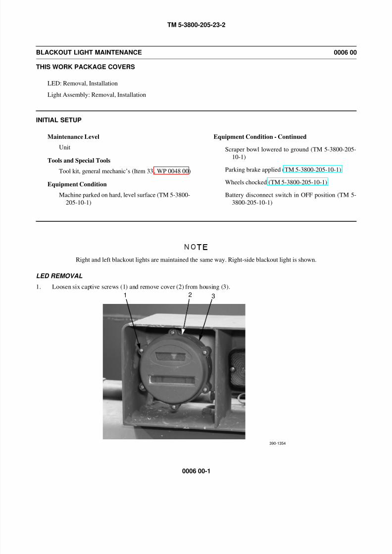
Right and left blackout lights are maintained the same way. Right-side blackout light is shown.
LED REMOVAL
1. Loosen six captive screws (1) and remove cover (2) from housing (3).
1 2 3
390-1354
8/14/2019 TM 5-3800-205-23-2 MODEL 613CS
http://slidepdf.com/reader/full/tm-5-3800-205-23-2-model-613cs 52/276
TM 5-3800-205-23-2
0006 00-2
BLACKOUT LIGHT MAINTENANCE - CONTINUED 0006 00
LED REMOVAL - CONTINUED
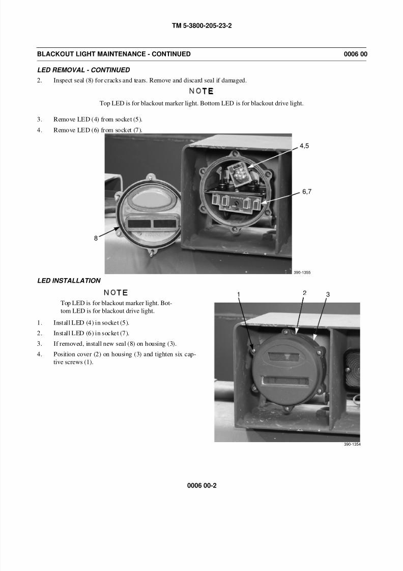
2. Inspect seal (8) for cracks and tears. Remove and discard seal if damaged.
NOTE
Top LED is for blackout marker light. Bottom LED is for blackout drive light.
3. Remove LED (4) from socket (5).
4. Remove LED (6) from socket (7).
LED INSTALLATION
NOTE
Top LED is for blackout marker light. Bot-
tom LED is for blackout drive light.
1. Install LED (4) in socket (5).
2. Install LED (6) in socket (7).
3. If removed, install new seal (8) on housing (3).
4. Position cover (2) on housing (3) and tighten six cap-
tive screws (1).
8
4,5
6,7
390-1355
1 2 3
390-1354

8/14/2019 TM 5-3800-205-23-2 MODEL 613CS
http://slidepdf.com/reader/full/tm-5-3800-205-23-2-model-613cs 53/276
TM 5-3800-205-23-2
0006 00-3
BLACKOUT LIGHT MAINTENANCE - CONTINUED 0006 00
LIGHT ASSEMBLY REMOVAL
1. Remove LEDs (Refer to LED Removal).
2. Remove three screws (9), washers (10), and access plate (12) from enclosure (11).
3. Remove two screws (15) and washers (16) from plate (13).
4. Disconnect two light assembly connectors (17) from wiring harness connectors (18).
5. Remove blackout light assembly (14) from plate (13).
9,10 11
390-1352
12
11
15,16
17
13
18
14
390-1353
8/14/2019 TM 5-3800-205-23-2 MODEL 613CS
http://slidepdf.com/reader/full/tm-5-3800-205-23-2-model-613cs 54/276
TM 5-3800-205-23-2
0006 00-4
BLACKOUT LIGHT MAINTENANCE - CONTINUED 0006 00
LIGHT ASSEMBLY INSTALLATION
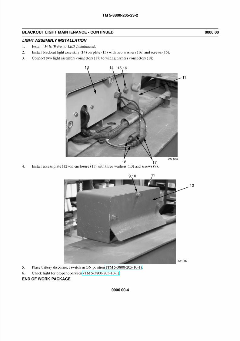
1. Install LEDs (Refer to LED Installation).
2. Install blackout light assembly (14) on plate (13) with two washers (16) and screws (15).
3. Connect two light assembly connectors (17) to wiring harness connectors (18).
4. Install access plate (12) on enclosure (11) with three washers (10) and screws (9).
5. Place battery disconnect switch in ON position (TM 5-3800-205-10-1).
6. Check light for proper operation (TM 5-3800-205-10-1).
END OF WORK PACKAGE
11
15,16
17
13
18
14
390-1353
9,10 11
390-1352
12
8/14/2019 TM 5-3800-205-23-2 MODEL 613CS
http://slidepdf.com/reader/full/tm-5-3800-205-23-2-model-613cs 55/276
TM 5-3800-205-23-2
0007 00-1
FUEL LEVEL SENDING UNIT AND DIAL SENSOR REPLACEMENT 0007 00
THIS WORK PACKAGE COVERS
Dial Sensor: Removal, Installation
Fuel Sending Unit: Removal, Installation
INITIAL SETUP
Maintenance Level
Unit
Tools and Special Tools
Tool kit, general mechanic’s (Item 33, WP 0048 00)
Materials/Parts
Fuel (Item 13, 14, or 15, WP 0047 00)
Rag, wiping (Item 31, WP 0047 00)
Gasket
O-ring
Washer, lock (6)
Equipment Condition
Machine parked on hard, level surface (TM 5-3800-
205-10-1)
Scraper bowl lowered to ground (TM 5-3800-205-
10-1)
Parking brake applied (TM 5-3800-205-10-1)
Wheels chocked (TM 5-3800-205-10-1)
Battery disconnect switch in OFF position (TM 5-
3800-205-10-1)
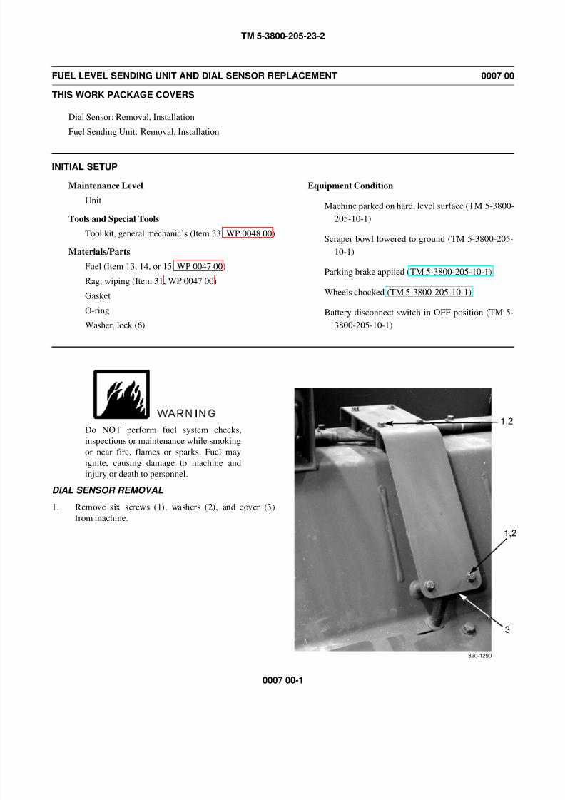
WARNING
Do NOT perform fuel system checks,
inspections or maintenance while smoking
or near fire, flames or sparks. Fuel may
ignite, causing damage to machine and
injury or death to personnel.
DIAL SENSOR REMOVAL
1. Remove six screws (1), washers (2), and cover (3)
from machine.
3
1,2
390-1290
1,2
8/14/2019 TM 5-3800-205-23-2 MODEL 613CS
http://slidepdf.com/reader/full/tm-5-3800-205-23-2-model-613cs 56/276
TM 5-3800-205-23-2
0007 00-2
FUEL LEVEL SENDING UNIT AND DIAL SENSOR REPLACEMENT - CONTINUED 0007 00
DIAL SENSOR REMOVAL - CONTINUED
NOTE
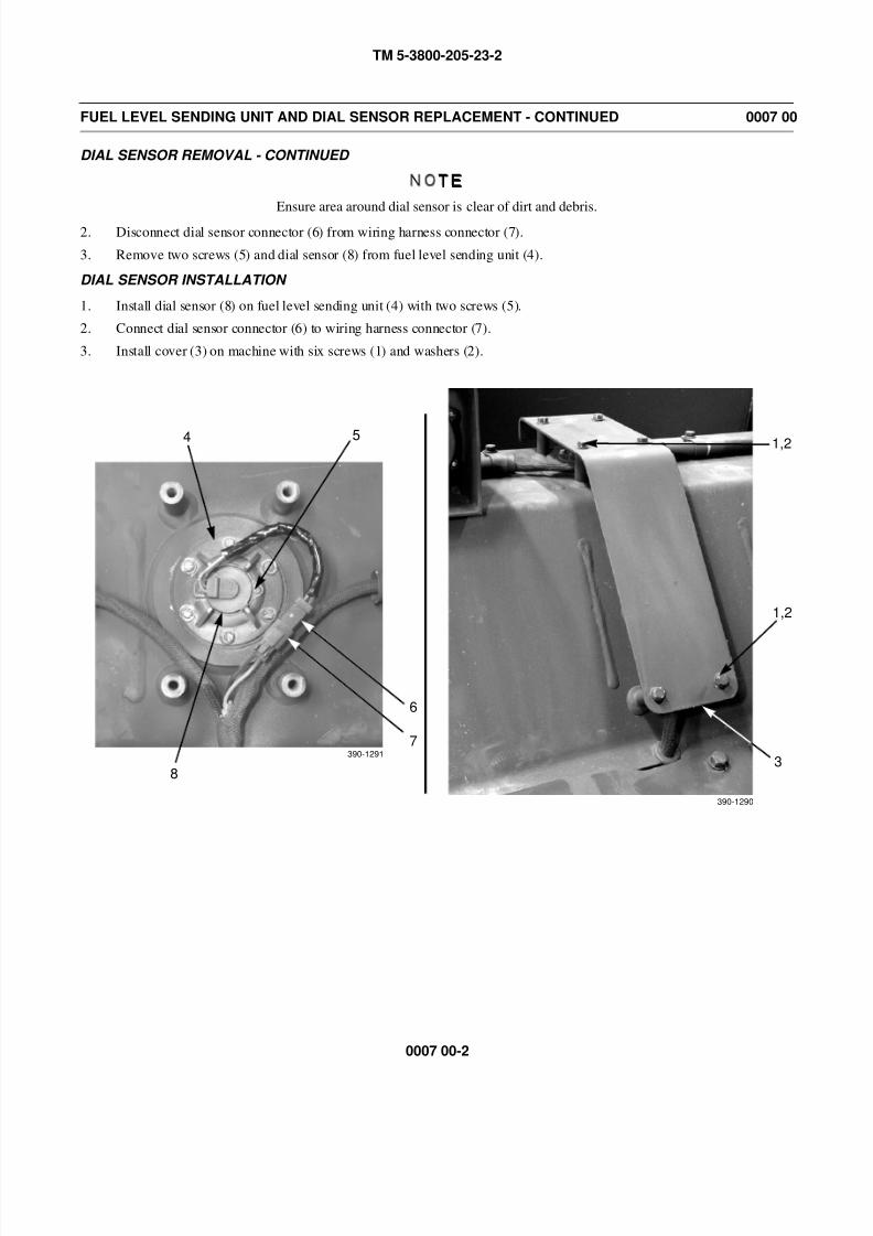
Ensure area around dial sensor is clear of dirt and debris.
2. Disconnect dial sensor connector (6) from wiring harness connector (7).
3. Remove two screws (5) and dial sensor (8) from fuel level sending unit (4).
DIAL SENSOR INSTALLATION
1. Install dial sensor (8) on fuel level sending unit (4) with two screws (5).
2. Connect dial sensor connector (6) to wiring harness connector (7).
3. Install cover (3) on machine with six screws (1) and washers (2).
3
1,2
390-1290
390-1291
4 5
6
7
8
1,2
8/14/2019 TM 5-3800-205-23-2 MODEL 613CS
http://slidepdf.com/reader/full/tm-5-3800-205-23-2-model-613cs 57/276
TM 5-3800-205-23-2
0007 00-3
FUEL LEVEL SENDING UNIT AND DIAL SENSOR REPLACEMENT - CONTINUED 0007 00
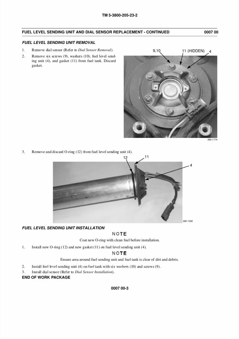
FUEL LEVEL SENDING UNIT REMOVAL
1. Remove dial sensor (Refer to Dial Sensor Removal).
2. Remove six screws (9), washers (10), fuel level send-
ing unit (4), and gasket (11) from fuel tank. Discard
gasket.
3. Remove and discard O-ring (12) from fuel level sending unit (4).
FUEL LEVEL SENDING UNIT INSTALLATION
NOTE
Coat new O-ring with clean fuel before installation.
1. Install new O-ring (12) and new gasket (11) on fuel level sending unit (4).
NOTE
Ensure area around fuel sending unit and fuel tank is clear of dirt and debris.
2. Install fuel level sending unit (4) on fuel tank with six washers (10) and screws (9).
3. Install dial sensor (Refer to Dial Sensor Installation).
END OF WORK PACKAGE
9,10 4
390-1774
11 (HIDDEN)
12 11
4
390-1292

8/14/2019 TM 5-3800-205-23-2 MODEL 613CS
http://slidepdf.com/reader/full/tm-5-3800-205-23-2-model-613cs 58/276
TM 5-3800-205-23-2
0007 00-4
This Page Intentionally Left Blank.
8/14/2019 TM 5-3800-205-23-2 MODEL 613CS
http://slidepdf.com/reader/full/tm-5-3800-205-23-2-model-613cs 59/276
TM 5-3800-205-23-2
0008 00-1
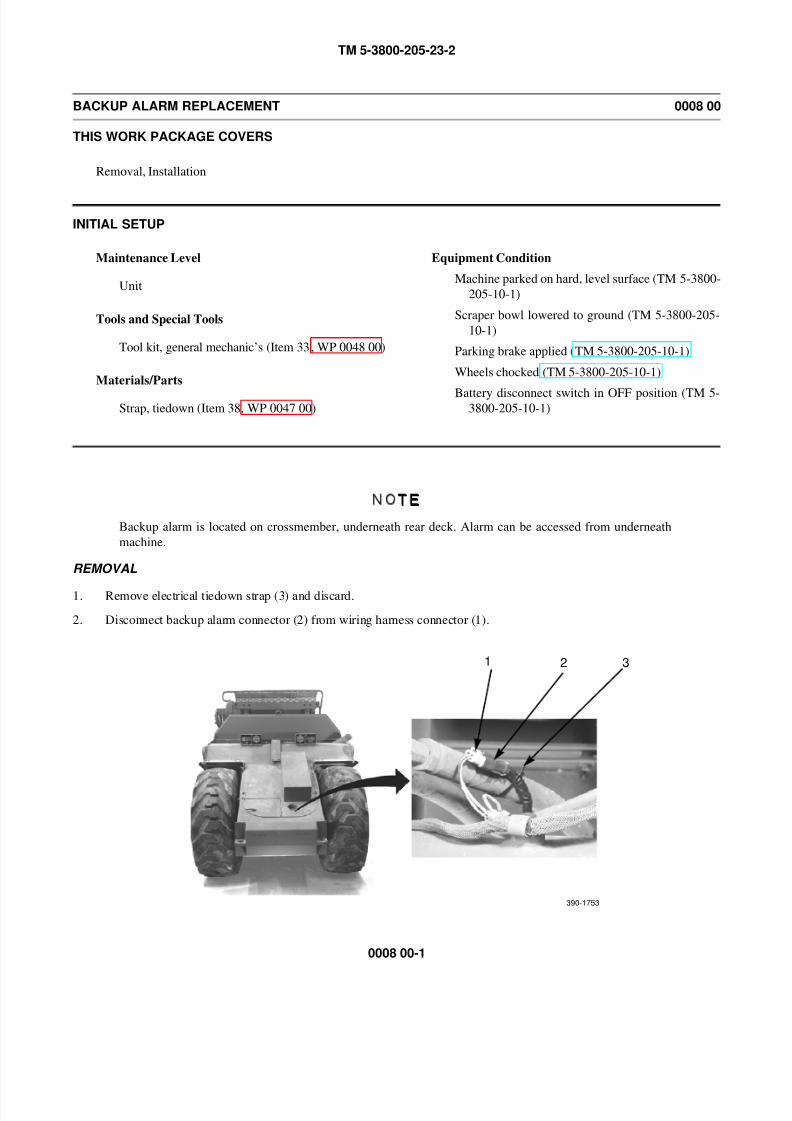
BACKUP ALARM REPLACEMENT 0008 00
THIS WORK PACKAGE COVERS
Removal, Installation
INITIAL SETUP
Maintenance Level
Unit
Tools and Special Tools
Tool kit, general mechanic’s (Item 33, WP 0048 00)
Materials/Parts
Strap, tiedown (Item 38, WP 0047 00)
Equipment Condition
Machine parked on hard, level surface (TM 5-3800-
205-10-1)
Scraper bowl lowered to ground (TM 5-3800-205-
10-1)
Parking brake applied (TM 5-3800-205-10-1)
Wheels chocked (TM 5-3800-205-10-1)
Battery disconnect switch in OFF position (TM 5-3800-205-10-1)
NOTE
Backup alarm is located on crossmember, underneath rear deck. Alarm can be accessed from underneath
machine.
REMOVAL
1. Remove electrical tiedown strap (3) and discard.
2. Disconnect backup alarm connector (2) from wiring harness connector (1).
1 2 3
390-1753
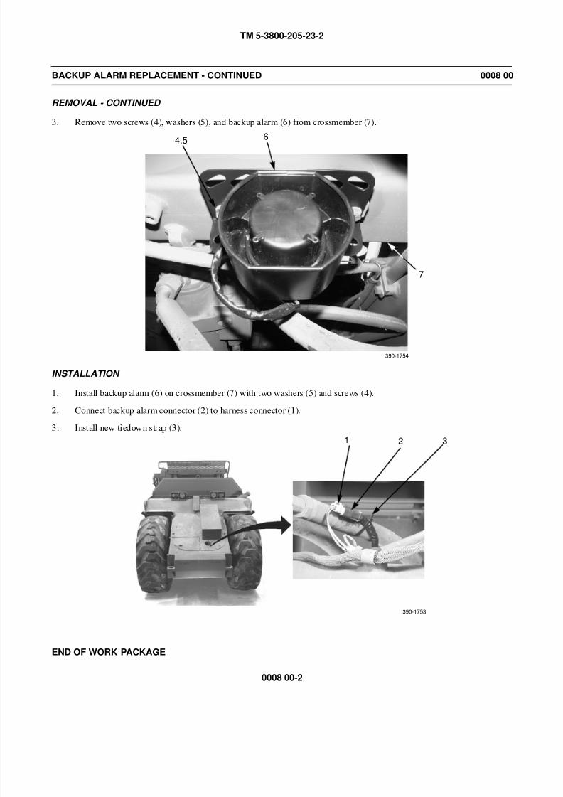
8/14/2019 TM 5-3800-205-23-2 MODEL 613CS
http://slidepdf.com/reader/full/tm-5-3800-205-23-2-model-613cs 60/276
TM 5-3800-205-23-2
0008 00-2
BACKUP ALARM REPLACEMENT - CONTINUED 0008 00
REMOVAL - CONTINUED
3. Remove two screws (4), washers (5), and backup alarm (6) from crossmember (7).
INSTALLATION
1. Install backup alarm (6) on crossmember (7) with two washers (5) and screws (4).
2. Connect backup alarm connector (2) to harness connector (1).
3. Install new tiedown strap (3).
END OF WORK PACKAGE
4,5 6
7
390-1754
1 2 3
390-1753
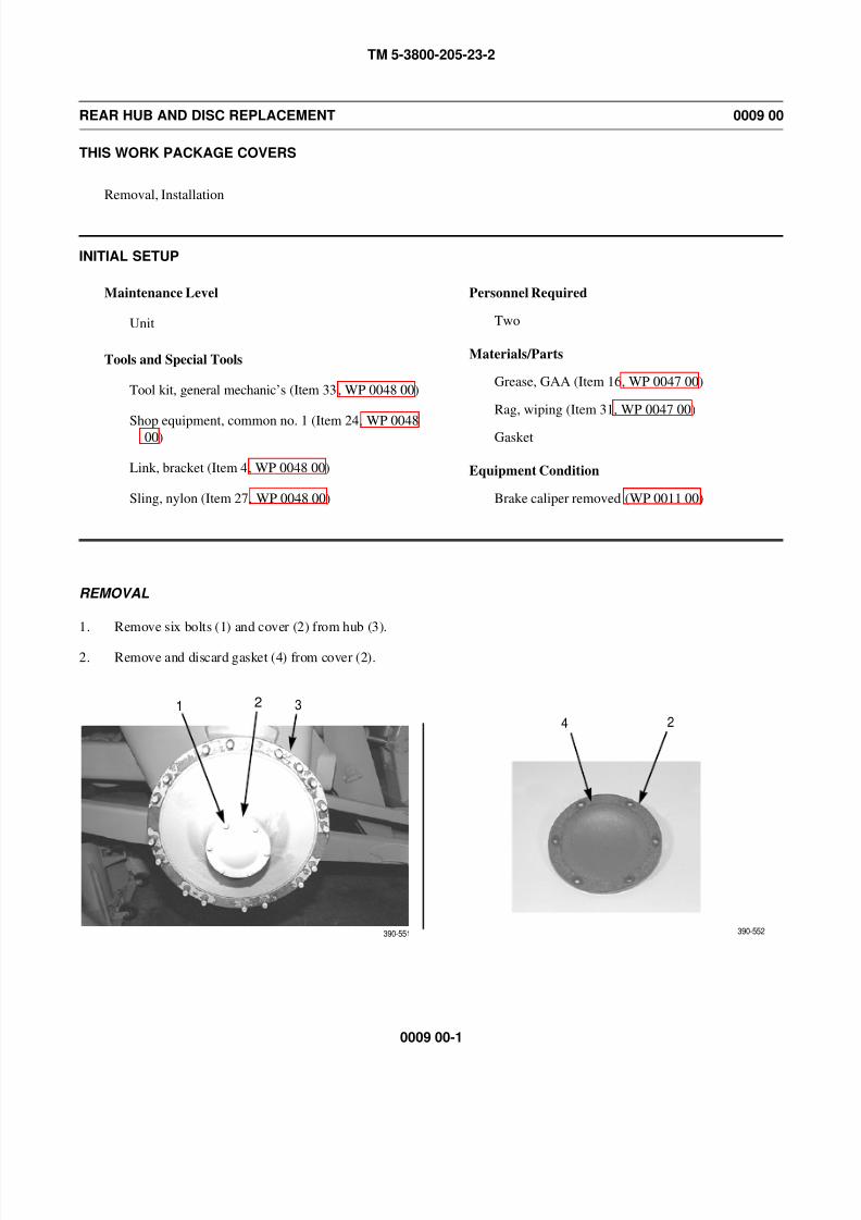
8/14/2019 TM 5-3800-205-23-2 MODEL 613CS
http://slidepdf.com/reader/full/tm-5-3800-205-23-2-model-613cs 61/276
TM 5-3800-205-23-2
0009 00-1
REAR HUB AND DISC REPLACEMENT 0009 00
THIS WORK PACKAGE COVERS
Removal, Installation
INITIAL SETUP
Maintenance Level
Unit
Tools and Special Tools
Tool kit, general mechanic’s (Item 33, WP 0048 00)
Shop equipment, common no. 1 (Item 24, WP 004800)
Link, bracket (Item 4, WP 0048 00)
Sling, nylon (Item 27, WP 0048 00)
Personnel Required
Two
Materials/Parts
Grease, GAA (Item 16, WP 0047 00)
Rag, wiping (Item 31, WP 0047 00)
Gasket
Equipment Condition
Brake caliper removed (WP 0011 00)
REMOVAL
1. Remove six bolts (1) and cover (2) from hub (3).
2. Remove and discard gasket (4) from cover (2).
1 2 3
4 2
390-551 390-552
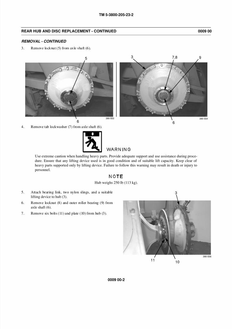
8/14/2019 TM 5-3800-205-23-2 MODEL 613CS
http://slidepdf.com/reader/full/tm-5-3800-205-23-2-model-613cs 62/276
TM 5-3800-205-23-2
0009 00-2
REAR HUB AND DISC REPLACEMENT - CONTINUED 0009 00
REMOVAL - CONTINUED
3. Remove locknut (5) from axle shaft (6).
4. Remove tab lockwasher (7) from axle shaft (6).
WARNING
Use extreme caution when handling heavy parts. Provide adequate support and use assistance during proce-
dure. Ensure that any lifting device used is in good condition and of suitable lift capacity. Keep clear of
heavy parts supported only by lifting device. Failure to follow this warning may result in death or injury to
personnel.
NOTE
Hub weighs 250 lb (113 kg).
5. Attach bearing link, two nylon slings, and a suitable
lifting device to hub (3).
6. Remove locknut (8) and outer roller bearing (9) from
axle shaft (6).
7. Remove six bolts (11) and plate (10) from hub (3).
5
6
7,8
6
390-553 390-554
3 9
3
11390-556
10
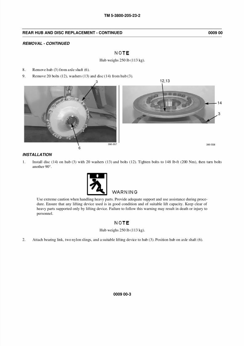
8/14/2019 TM 5-3800-205-23-2 MODEL 613CS
http://slidepdf.com/reader/full/tm-5-3800-205-23-2-model-613cs 63/276
TM 5-3800-205-23-2
0009 00-3
REAR HUB AND DISC REPLACEMENT - CONTINUED 0009 00
REMOVAL - CONTINUED
NOTE
Hub weighs 250 lb (113 kg).
8. Remove hub (3) from axle shaft (6).
9. Remove 20 bolts (12), washers (13) and disc (14) from hub (3).
INSTALLATION
1. Install disc (14) on hub (3) with 20 washers (13) and bolts (12). Tighten bolts to 148 lb-ft (200 Nm), then turn bolts
another 90°.
WARNING
Use extreme caution when handling heavy parts. Provide adequate support and use assistance during proce-
dure. Ensure that any lifting device used is in good condition and of suitable lift capacity. Keep clear of
heavy parts supported only by lifting device. Failure to follow this warning may result in death or injury to
personnel.
NOTE
Hub weighs 250 lb (113 kg).
2. Attach bearing link, two nylon slings, and a suitable lifting device to hub (3). Position hub on axle shaft (6).
3
6
12,13
14
3
390-557 390-558
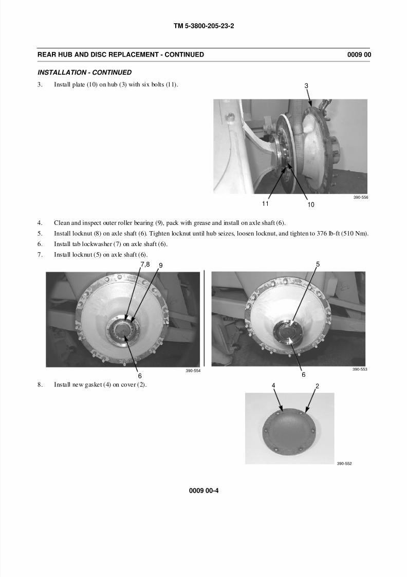
8/14/2019 TM 5-3800-205-23-2 MODEL 613CS
http://slidepdf.com/reader/full/tm-5-3800-205-23-2-model-613cs 64/276
TM 5-3800-205-23-2
0009 00-4
REAR HUB AND DISC REPLACEMENT - CONTINUED 0009 00
INSTALLATION - CONTINUED
3. Install plate (10) on hub (3) with six bolts (11).
4. Clean and inspect outer roller bearing (9), pack with grease and install on axle shaft (6).
5. Install locknut (8) on axle shaft (6). Tighten locknut until hub seizes, loosen locknut, and tighten to 376 lb-ft (510 Nm).
6. Install tab lockwasher (7) on axle shaft (6).
7. Install locknut (5) on axle shaft (6).
8. Install new gasket (4) on cover (2).
3
11
390-556
10
5
6
7,8
6390-553390-554
9
390-552
4 2
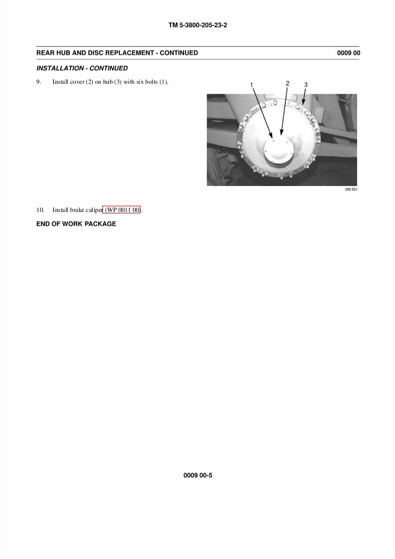
8/14/2019 TM 5-3800-205-23-2 MODEL 613CS
http://slidepdf.com/reader/full/tm-5-3800-205-23-2-model-613cs 65/276
TM 5-3800-205-23-2
0009 00-5
REAR HUB AND DISC REPLACEMENT - CONTINUED 0009 00
INSTALLATION - CONTINUED
9. Install cover (2) on hub (3) with six bolts (1).
10. Install brake caliper (WP 0011 00).
END OF WORK PACKAGE
1 2 3
390-551

8/14/2019 TM 5-3800-205-23-2 MODEL 613CS
http://slidepdf.com/reader/full/tm-5-3800-205-23-2-model-613cs 66/276
TM 5-3800-205-23-2
0009 00-6
This Page Intentionally Left Blank.
8/14/2019 TM 5-3800-205-23-2 MODEL 613CS
http://slidepdf.com/reader/full/tm-5-3800-205-23-2-model-613cs 67/276
TM 5-3800-205-23-2
0010 00-1
AIR/HYDRAULIC BRAKE CYLINDER REPLACEMENT 0010 00
THIS WORK PACKAGE COVERS
Removal, Installation
INITIAL SETUP
Maintenance Level
Unit
Tools and Special Tools
Tool kit, general mechanic’s (Item 33, WP 0048 00)
Shop equipment, common no. 1 (Item 24, WP 0048
00)
Materials/Parts
Cap set, protective (Item 5, WP 0047 00)
Tag, marker (Item 39, WP 0047 00)
Tape, antiseizing (Item 40, WP 0047 00)
Personnel Required
Two
References
WP 0014 00
Equipment Condition
Air tube disconnected from quick release valve
(WP 0013 00)
Machine parked on hard, level surface (TM 5-3800-
205-10-1)
Scraper bowl lowered to ground (TM 5-3800-205-
10-1)
Parking brake applied (TM 5-3800-205-10-1)
Wheels chocked (TM 5-3800-205-10-1)
Battery disconnect switch in OFF position (TM 5-
3800-205-10-1)
WARNING
• Do NOT disconnect any air system lines or fittings unless engine is shut down and air system
pressure is relieved. Failure to follow this warning could result in serious injury to personnel.
• Always wear eye protection when disconnecting air lines. Residual air will be expelled. Failure
to follow this warning may result in serious eye injury.
CAUTION
Cap all tubes to prevent fluid loss and contamination of brake fluid.
NOTE
• Tag all tubes to aid in installation.
• Care must be taken to ensure that fluids are contained during performance of inspection, main-
tenance, testing, adjusting and repair of the machine. Be prepared to collect fluid with suitable
containers before opening any compartment or disassembling any component containing flu-
ids.
• Dispose of all fluids according to local regulations and mandates.

8/14/2019 TM 5-3800-205-23-2 MODEL 613CS
http://slidepdf.com/reader/full/tm-5-3800-205-23-2-model-613cs 68/276
TM 5-3800-205-23-2
0010 00-2
AIR/HYDRAULIC BRAKE CYLINDER REPLACEMENT - CONTINUED 0010 00
REMOVAL
CAUTION
Always use two wrenches on fittings when removing brake lines. Failure to do so may damage fittings.
1. Loosen nut (2) and disconnect tube (1) from air/hydraulic brake cylinder (3). Install protective cap on tube.
2. Remove two screws (4), washers (5), and electrical
leads (6) from air/hydraulic brake cylinder (3).
3. Disconnect vent tube (7) from air/hydraulic brake cyl-
inder (3).
3 2 1
390-585
390-586
4,5 6
73
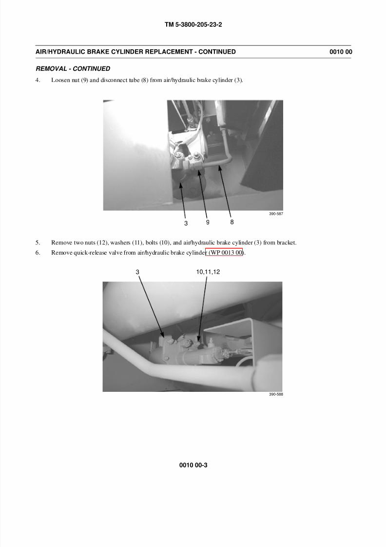
8/14/2019 TM 5-3800-205-23-2 MODEL 613CS
http://slidepdf.com/reader/full/tm-5-3800-205-23-2-model-613cs 69/276
TM 5-3800-205-23-2
0010 00-3
AIR/HYDRAULIC BRAKE CYLINDER REPLACEMENT - CONTINUED 0010 00
REMOVAL - CONTINUED
4. Loosen nut (9) and disconnect tube (8) from air/hydraulic brake cylinder (3).
5. Remove two nuts (12), washers (11), bolts (10), and air/hydraulic brake cylinder (3) from bracket.
6. Remove quick-release valve from air/hydraulic brake cylinder (WP 0013 00).
3 89
390-587
3 10,11,12
390-588

8/14/2019 TM 5-3800-205-23-2 MODEL 613CS
http://slidepdf.com/reader/full/tm-5-3800-205-23-2-model-613cs 70/276
TM 5-3800-205-23-2
0010 00-4
AIR/HYDRAULIC BRAKE CYLINDER REPLACEMENT - CONTINUED 0010 00
INSTALLATION
1. Install quick-release valve to air/hydraulic brake cylinder (3) (WP 0013 00).
2. Install air/hydraulic brake cylinder (3) on bracket with two bolts (10), washers (11), and nuts (12).
NOTE
Remove old antiseizing tape and apply new antizseizing tape to male threads of air system fitting before
connection is made.
3. Connect vent tube (7) to air/hydraulic brake cylinder (3).
3 10,11,12
390-588
390-586
73
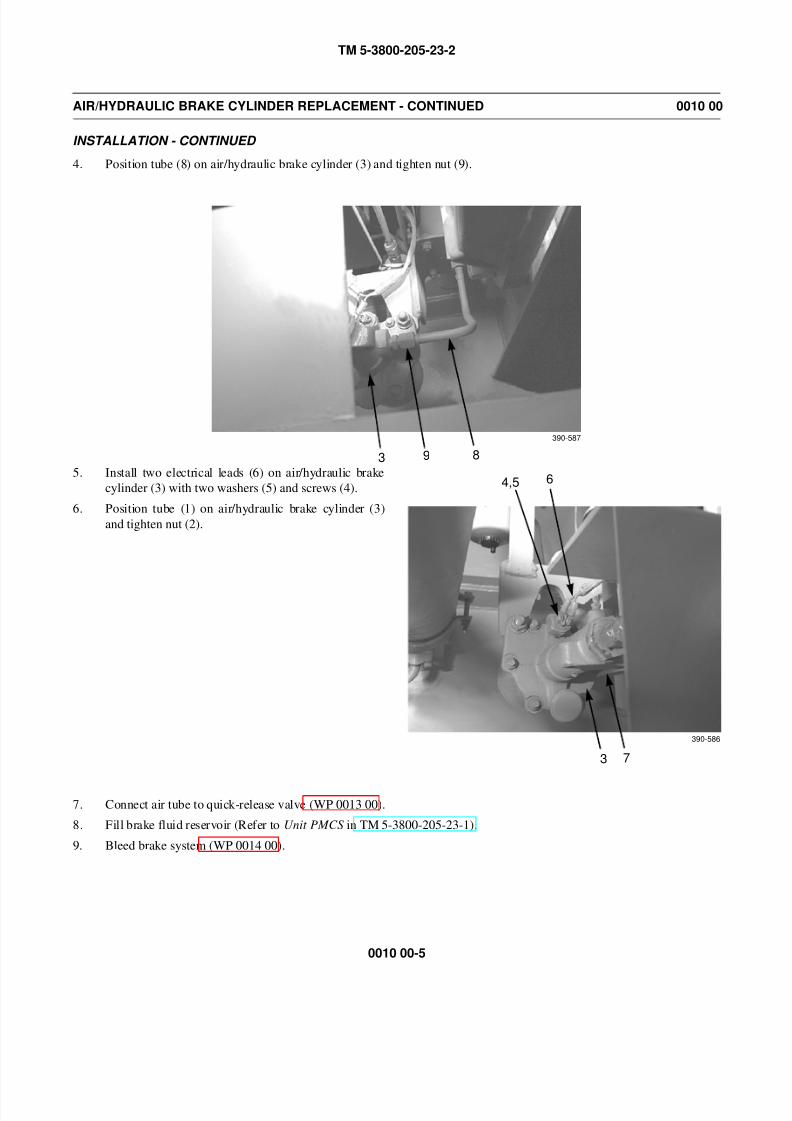
8/14/2019 TM 5-3800-205-23-2 MODEL 613CS
http://slidepdf.com/reader/full/tm-5-3800-205-23-2-model-613cs 71/276
TM 5-3800-205-23-2
0010 00-5
AIR/HYDRAULIC BRAKE CYLINDER REPLACEMENT - CONTINUED 0010 00
INSTALLATION - CONTINUED
4. Position tube (8) on air/hydraulic brake cylinder (3) and tighten nut (9).
5. Install two electrical leads (6) on air/hydraulic brake
cylinder (3) with two washers (5) and screws (4).
6. Position tube (1) on air/hydraulic brake cylinder (3)
and tighten nut (2).
7. Connect air tube to quick-release valve (WP 0013 00).
8. Fill brake fluid reservoir (Refer to Unit PMCS in TM 5-3800-205-23-1).
9. Bleed brake system (WP 0014 00).
3 89
390-587
390-586
4,5 6
73
8/14/2019 TM 5-3800-205-23-2 MODEL 613CS
http://slidepdf.com/reader/full/tm-5-3800-205-23-2-model-613cs 72/276
TM 5-3800-205-23-2
0010 00-6
AIR/HYDRAULIC BRAKE CYLINDER REPLACEMENT - CONTINUED 0010 00
INSTALLATION - CONTINUED
WARNING
If machine is parked indoors, DO NOT run engine unless exhaust fumes are vented to the outside. Failure to
follow this warning may cause injury or death due to carbon monoxide poisoning.
10. Start engine and apply and release brakes (TM 5-3800-205-10-1). With assistance, check for air and brake fluid leaks.
END OF WORK PACKAGE
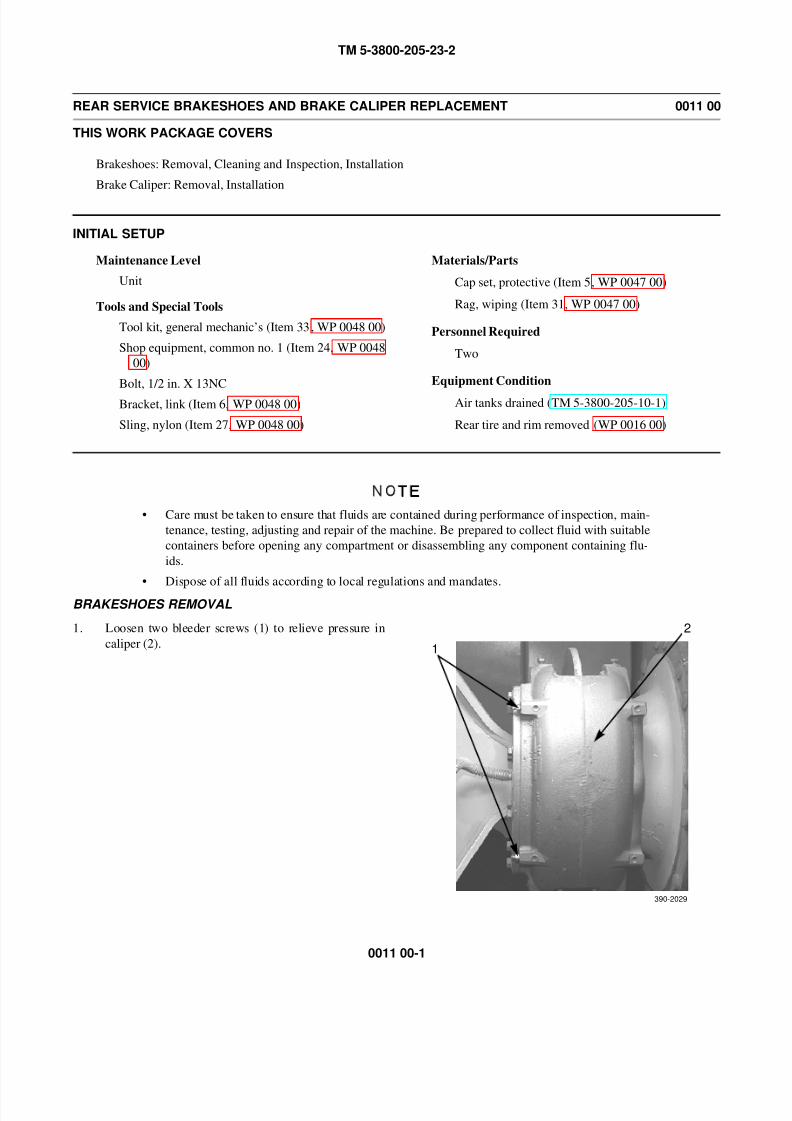
8/14/2019 TM 5-3800-205-23-2 MODEL 613CS
http://slidepdf.com/reader/full/tm-5-3800-205-23-2-model-613cs 73/276
TM 5-3800-205-23-2
0011 00-1
REAR SERVICE BRAKESHOES AND BRAKE CALIPER REPLACEMENT 0011 00
THIS WORK PACKAGE COVERS
Brakeshoes: Removal, Cleaning and Inspection, Installation
Brake Caliper: Removal, Installation
INITIAL SETUP
Maintenance Level
Unit
Tools and Special Tools
Tool kit, general mechanic’s (Item 33, WP 0048 00)
Shop equipment, common no. 1 (Item 24, WP 0048
00)
Bolt, 1/2 in. X 13NC
Bracket, link (Item 6, WP 0048 00)
Sling, nylon (Item 27, WP 0048 00)
Materials/Parts
Cap set, protective (Item 5, WP 0047 00)
Rag, wiping (Item 31, WP 0047 00)
Personnel Required
Two
Equipment Condition
Air tanks drained (TM 5-3800-205-10-1)
Rear tire and rim removed (WP 0016 00)
NOTE
• Care must be taken to ensure that fluids are contained during performance of inspection, main-
tenance, testing, adjusting and repair of the machine. Be prepared to collect fluid with suitable
containers before opening any compartment or disassembling any component containing flu-
ids.
• Dispose of all fluids according to local regulations and mandates.
BRAKESHOES REMOVAL
1. Loosen two bleeder screws (1) to relieve pressure in
caliper (2). 1
2
390-2029
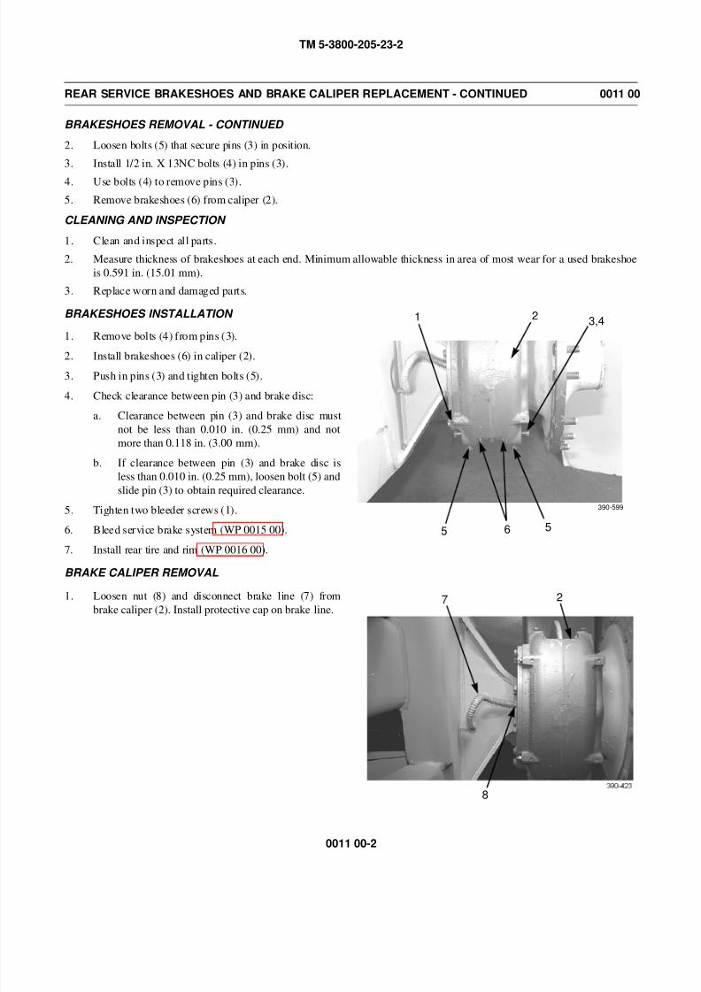
8/14/2019 TM 5-3800-205-23-2 MODEL 613CS
http://slidepdf.com/reader/full/tm-5-3800-205-23-2-model-613cs 74/276
TM 5-3800-205-23-2
0011 00-2
REAR SERVICE BRAKESHOES AND BRAKE CALIPER REPLACEMENT - CONTINUED 0011 00
BRAKESHOES REMOVAL - CONTINUED
2. Loosen bolts (5) that secure pins (3) in position.
3. Install 1/2 in. X 13NC bolts (4) in pins (3).
4. Use bolts (4) to remove pins (3).
5. Remove brakeshoes (6) from caliper (2).
CLEANING AND INSPECTION
1. Clean and inspect all parts.
2. Measure thickness of brakeshoes at each end. Minimum allowable thickness in area of most wear for a used brakeshoe
is 0.591 in. (15.01 mm).
3. Replace worn and damaged parts.
BRAKESHOES INSTALLATION
1. Remove bolts (4) from pins (3).
2. Install brakeshoes (6) in caliper (2).
3. Push in pins (3) and tighten bolts (5).
4. Check clearance between pin (3) and brake disc:
a. Clearance between pin (3) and brake disc must
not be less than 0.010 in. (0.25 mm) and not
more than 0.118 in. (3.00 mm).
b. If clearance between pin (3) and brake disc is
less than 0.010 in. (0.25 mm), loosen bolt (5) and
slide pin (3) to obtain required clearance.
5. Tighten two bleeder screws (1).
6. Bleed service brake system (WP 0015 00).
7. Install rear tire and rim (WP 0016 00).
BRAKE CALIPER REMOVAL
1. Loosen nut (8) and disconnect brake line (7) from
brake caliper (2). Install protective cap on brake line.
3,42
565
390-599
1
7
8
2

8/14/2019 TM 5-3800-205-23-2 MODEL 613CS
http://slidepdf.com/reader/full/tm-5-3800-205-23-2-model-613cs 75/276
TM 5-3800-205-23-2
0011 00-3
REAR SERVICE BRAKESHOES AND BRAKE CALIPER REPLACEMENT - CONTINUED 0011 00
BRAKE CALIPER REMOVAL - CONTINUED
2. Remove two bolts from brake caliper (2) and install two links on caliper.
WARNING
Use extreme caution when handling heavy parts. Provide adequate support and use assistance during proce-
dure. Ensure that any lifting device used is in good condition and of suitable load capacity. Keep clear of
heavy parts supported only by lifting device. Failure to follow this warning may result in death or injury to
personnel.
3. Attach nylon sling to links and suitable lifting device.
NOTE
Brake caliper weighs 90 lb (1 kg).
4. With assistance, remove eight screws (9), washers
(10), and brake caliper (2) from axle housing (11).
5. If replacing brake caliper (2), remove links from cali-
per.
BRAKE CALIPER INSTALLATION
1. If installing a new brake caliper (2), remove two bolts from caliper and install two links.
WARNING
Use extreme caution when handling heavy parts. Provide adequate support and use assistance during proce-
dure. Ensure that any lifting device used is in good condition and of suitable load capacity. Keep clear of
heavy parts supported only by lifting device. Failure to follow this warning may result in death or injury to
personnel.
NOTE
Brake caliper weighs 90 lb (1 kg).
2. Attach nylon sling to links and suitable lifting device.
2 9,10
390-42411
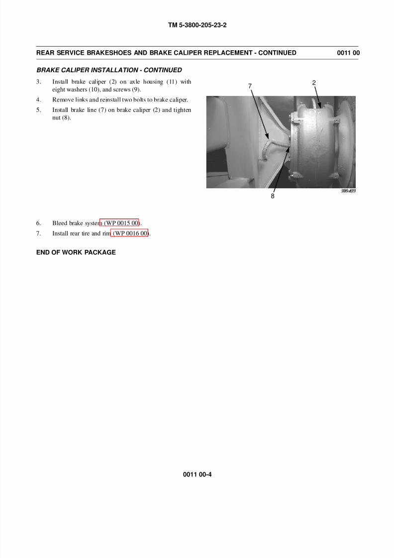
8/14/2019 TM 5-3800-205-23-2 MODEL 613CS
http://slidepdf.com/reader/full/tm-5-3800-205-23-2-model-613cs 76/276
TM 5-3800-205-23-2
0011 00-4
REAR SERVICE BRAKESHOES AND BRAKE CALIPER REPLACEMENT - CONTINUED 0011 00
BRAKE CALIPER INSTALLATION - CONTINUED
3. Install brake caliper (2) on axle housing (11) with
eight washers (10), and screws (9).
4. Remove links and reinstall two bolts to brake caliper.
5. Install brake line (7) on brake caliper (2) and tighten
nut (8).
6. Bleed brake system (WP 0015 00).
7. Install rear tire and rim (WP 0016 00).
END OF WORK PACKAGE
7
8
2
390-423
8/14/2019 TM 5-3800-205-23-2 MODEL 613CS
http://slidepdf.com/reader/full/tm-5-3800-205-23-2-model-613cs 77/276
TM 5-3800-205-23-2
0012 00-1
AIR HOSE AND TUBES REPLACEMENT 0012 00
THIS WORK PACKAGE COVERS
Air Hose: Removal, Installation
Air Tube: Removal, Installation
INITIAL SETUP
Maintenance Level
Unit
Tools and Special Tools
Tool kit, general mechanic’s (Item 33, WP 0048 00)
Materials/Parts
Strap, tiedown (Item 38, WP 0047 00)
Tag, marker (Item 39, WP 0047 00)
Tape, antizeizing (Item 40, WP 0047 00)
O-ring (as required)
Equipment Condition
Machine parked on hard, level surface (TM 5-3800-
205-10-1)
Scraper bowl lowered to ground (TM 5-3800-205-
10-1)
Ejector in forward position (TM 3800-205-10-1)
Parking brake applied (TM 5-3800-205-10-1)
Wheels chocked (TM 5-3800-205-10-1)
Battery disconnect switch in OFF position (TM 5-
3800-205-10-1)
Air tanks drained (TM 5-3800-205-10-1)
Toolbox and rear deck cover removed, if required
for access (WP 0017 00)
WARNING
• Do NOT disconnect any air system lines or fittings unless engine is shut down and air system
pressure is relieved. Failure to follow this warning could result in serious injury to personnel.
• Always wear eye protection when disconnecting air lines. Residual air will be expelled. Failure
to follow this warning may result in serious eye injury.
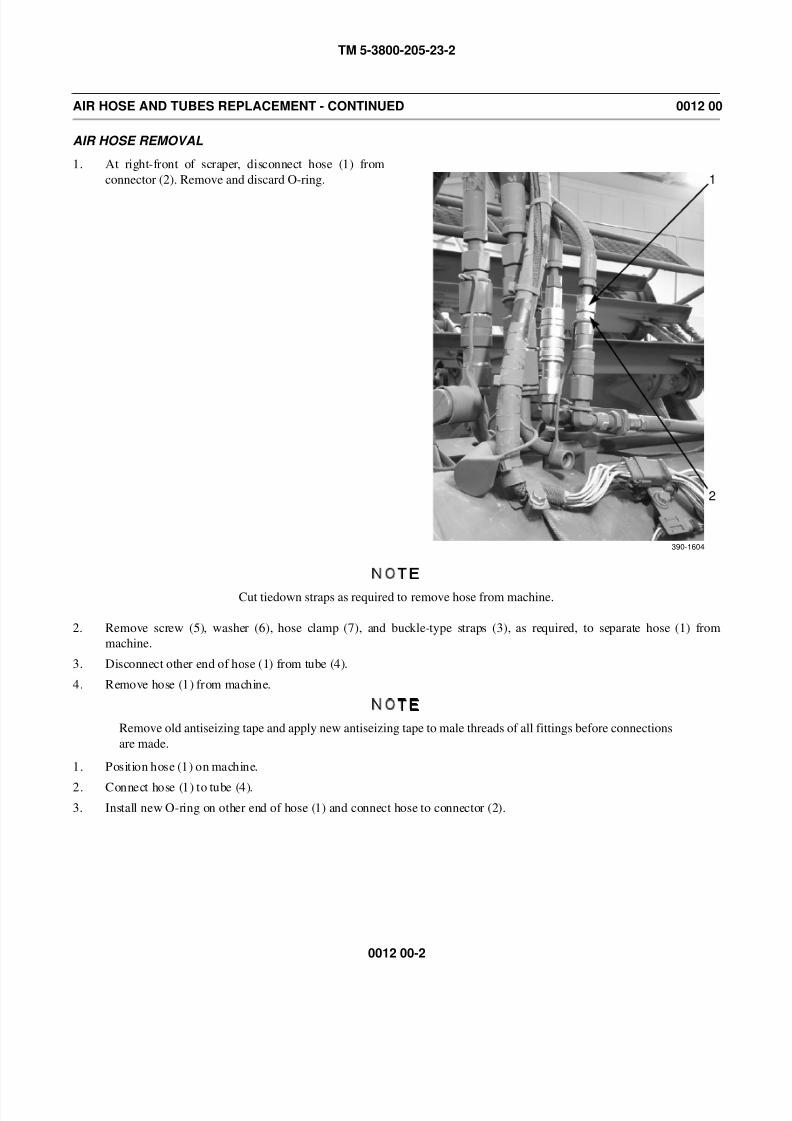
8/14/2019 TM 5-3800-205-23-2 MODEL 613CS
http://slidepdf.com/reader/full/tm-5-3800-205-23-2-model-613cs 78/276
TM 5-3800-205-23-2
0012 00-2
AIR HOSE AND TUBES REPLACEMENT - CONTINUED 0012 00
AIR HOSE REMOVAL
1. At right-front of scraper, disconnect hose (1) from
connector (2). Remove and discard O-ring.
NOTE
Cut tiedown straps as required to remove hose from machine.
2. Remove screw (5), washer (6), hose clamp (7), and buckle-type straps (3), as required, to separate hose (1) from
machine.
3. Disconnect other end of hose (1) from tube (4).
4. Remove hose (1) from machine.
NOTE
Remove old antiseizing tape and apply new antiseizing tape to male threads of all fittings before connections
are made.
1. Position hose (1) on machine.
2. Connect hose (1) to tube (4).
3. Install new O-ring on other end of hose (1) and connect hose to connector (2).
1
2
390-1604
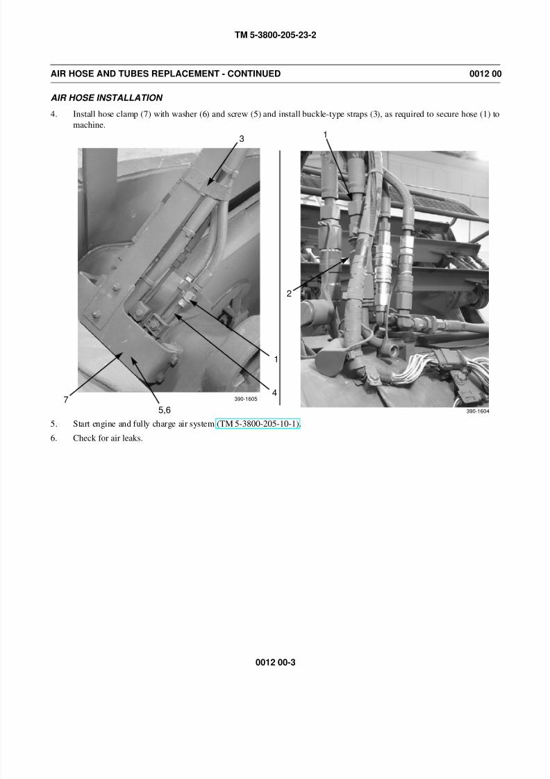
8/14/2019 TM 5-3800-205-23-2 MODEL 613CS
http://slidepdf.com/reader/full/tm-5-3800-205-23-2-model-613cs 79/276
TM 5-3800-205-23-2
0012 00-3
AIR HOSE AND TUBES REPLACEMENT - CONTINUED 0012 00
AIR HOSE INSTALLATION
4. Install hose clamp (7) with washer (6) and screw (5) and install buckle-type straps (3), as required to secure hose (1) to
machine.
5. Start engine and fully charge air system (TM 5-3800-205-10-1).
6. Check for air leaks.
1
390-1604
2
3
1
4
5,6
7 390-1605
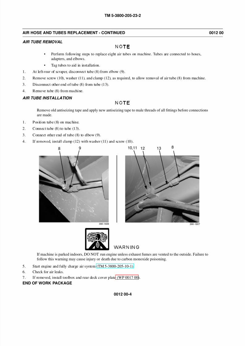
8/14/2019 TM 5-3800-205-23-2 MODEL 613CS
http://slidepdf.com/reader/full/tm-5-3800-205-23-2-model-613cs 80/276
TM 5-3800-205-23-2
0012 00-4
AIR HOSE AND TUBES REPLACEMENT - CONTINUED 0012 00
AIR TUBE REMOVAL
NOTE
• Perform following steps to replace eight air tubes on machine. Tubes are connected to hoses,
adapters, and elbows.• Tag tubes to aid in installation.
1. At left-rear of scraper, disconnect tube (8) from elbow (9).
2. Remove screw (10), washer (11), and clamp (12), as required, to allow removal of air tube (8) from machine.
3. Disconnect other end of tube (8) from tube (13).
4. Remove tube (8) from machine.
AIR TUBE INSTALLATION
NOTE
Remove old antiseizing tape and apply new antiseizing tape to male threads of all fittings before connections
are made.
1. Position tube (8) on machine.
2. Connect tube (8) to tube (13).
3. Connect other end of tube (8) to elbow (9).
4. If removed, install clamp (12) with washer (11) and screw (10).
WARNING
If machine is parked indoors, DO NOT run engine unless exhaust fumes are vented to the outside. Failure to
follow this warning may cause injury or death due to carbon monoxide poisoning.
5. Start engine and fully charge air system (TM 5-3800-205-10-1).
6. Check for air leaks.
7. If removed, install toolbox and rear deck cover plate (WP 0017 00).
END OF WORK PACKAGE
8 9 10,11 12 13 8
390-1606 390-1607
8/14/2019 TM 5-3800-205-23-2 MODEL 613CS
http://slidepdf.com/reader/full/tm-5-3800-205-23-2-model-613cs 81/276
TM 5-3800-205-23-2
0013 00-1
QUICK-RELEASE VALVE REPLACEMENT 0013 00
THIS WORK PACKAGE COVERS
Removal, Installation
INITIAL SETUP
Maintenance Level
Unit
Tools and Special Tools
Tool kit, general mechanic’s (Item 33, WP 0048 00)
Materials/Parts
Tape, antiseizing (Item 40, WP 0047 00)
Equipment Condition
Machine parked on hard, level surface (TM 5-3800-
205-10-1)
Equipment Condition - Continued
Scraper bowl lowered to ground (TM 5-3800-205-
10-1)
Parking brake applied (TM 5-3800-205-10-1)
Wheels chocked (TM 5-3800-205-10-1)
Battery disconnect switch in OFF position (TM 5-
3800-205-10-1)
Air tanks drained (TM 5-3800-205-10-1)
Rear compartment access door open (TM 5-3800-
205-10-1)
WARNING
• Do NOT disconnect any air system lines or fittings unless engine is shut down and air system
pressure is relieved. Failure to follow this warning could result in serious injury to personnel.
• Always wear eye protection when disconnecting air lines. Residual air will be expelled. Failure
to follow this warning may result in serious eye injury.
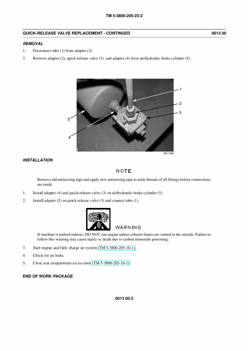
8/14/2019 TM 5-3800-205-23-2 MODEL 613CS
http://slidepdf.com/reader/full/tm-5-3800-205-23-2-model-613cs 82/276
TM 5-3800-205-23-2
0013 00-2
QUICK-RELEASE VALVE REPLACEMENT - CONTINUED 0013 00
REMOVAL
1. Disconnect tube (1) from adapter (2).
2. Remove adapter (2), quick-release valve (3), and adapter (4) from air/hydraulic brake cylinder (5).
INSTALLATION
NOTE
Remove old antiseizing tape and apply new antiseizing tape to male threads of all fittings before connections
are made.
1. Install adapter (4) and quick-release valve (3) on air/hydraulic brake cylinder (5).
2. Install adapter (2) on quick-release valve (3) and connect tube (1).
WARNING
If machine is parked indoors, DO NOT run engine unless exhaust fumes are vented to the outside. Failure to
follow this warning may cause injury or death due to carbon monoxide poisoning.
3. Start engine and fully charge air system (TM 5-3800-205-10-1).
4. Check for air leaks.
5. Close rear compartment access door (TM 5-3800-205-10-1).
END OF WORK PACKAGE
1
2
3
4
5
390-1608
8/14/2019 TM 5-3800-205-23-2 MODEL 613CS
http://slidepdf.com/reader/full/tm-5-3800-205-23-2-model-613cs 83/276
TM 5-3800-205-23-2
0014 00-1
BRAKE LINES REPLACEMENT 0014 00
THIS WORK PACKAGE COVERS
Tube Assemblies: Removal, Installation
Caliper Brake Hose Assembly: Removal, Installation
INITIAL SETUP
Maintenance Level
Unit
Tools and Special Tools
Tool kit, general mechanic’s (Item 33, WP 0048 00)
Shop equipment, common no. 1 (Item 24, WP 0048
00)
Materials/Parts
Cap set, protective (Item 5, WP 0047 00)
Rag, wiping (Item 31, WP 0047 00)
Tag, marker (Item 39, WP 0047 00)
References
WP 0015 00
Personnel Required
Two
Equipment Condition
Rear tires and rims removed (WP 0016 00)
TUBE ASSEMBLIES REMOVAL
CAUTION
• Always use two wrenches on fittings when removing brake lines. Failure to do so may damage fittings.
• Cap all lines to prevent fluid loss and contamination of brake system.
NOTE
• Tag all lines to aid in installation.
• Care must be taken to ensure that fluids are contained during maintenance of machine. Be prepared to
collect fluid with suitable containers before opening any component or disassembling any component
containing fluids. Ensure all spills are cleaned up.
• Dispose of all fluids according to local regulations and mandates.

8/14/2019 TM 5-3800-205-23-2 MODEL 613CS
http://slidepdf.com/reader/full/tm-5-3800-205-23-2-model-613cs 84/276
TM 5-3800-205-23-2
0014 00-2
BRAKE LINES REPLACEMENT - CONTINUED 0014 00
TUBE ASSEMBLIES REMOVAL
1. Loosen nut (6) and disconnect tube assembly (7) from air/hydraulic brake cylinder (5).
2. Loosen nut (4) from tee fitting (3) and remove tube assembly (7).
NOTE
Removal of left-side tube assembly, from tee fitting to brake caliper hose, is shown. Removal of right-side
tube assembly is the same, except for quantity of clamps that secure tube assembly to scraper frame.
3. Loosen nut (2) and disconnect tube assembly (1) from tee fitting (3).
4. Loosen nut (11) and disconnect tube assembly (1) from elbow (12).
5. Remove three nuts (9), washers (10), and clamps (8) from studs (13). Remove tube assembly (1) from clamps.
TUBE ASSEMBLIES INSTALLATION
CAUTION
• Always use two wrenches on fittings when installing brake lines. Failure to do so may damage fittings.
• Care must be taken to ensure tube assembly nuts are not cross-threaded during installation.
NOTE
Installation of left-side tube assembly, from tee fitting to brake caliper hose, is shown. Installation of right-
side tube assembly is the same, except for quantity of clamps that secure tube assembly to scraper frame.
1. Place tube assembly (1) inside three clamps (8) and position clamps on studs (13).
2. Install three washers (10) and nuts (9) to secure tube assembly (1) and clamps (13) to scraper frame.
1 2 34
5
6
78
9,101112
13

8/14/2019 TM 5-3800-205-23-2 MODEL 613CS
http://slidepdf.com/reader/full/tm-5-3800-205-23-2-model-613cs 85/276
TM 5-3800-205-23-2
0014 00-3
BRAKE LINES REPLACEMENT - CONTINUED 0014 00
TUBE ASSEMBLIES INSTALLATION - CONTINUED
3. Connect tube assembly (1) to elbow (12) and tighten nut (11).
4. Connect tube assembly (1) to tee fitting (3) and tighten nut (2).5. Connect tube assembly (7) to tee fitting (3) and tighten nut (4).
6. Connect tube assembly (7) to air/hydraulic brake cylinder (5) and tighten nut (6).
7. Bleed brake system (WP 0015 00).
8. Install rear tires and rims (WP 0016 00).
BRAKE CALIPER HOSE ASSEMBLY REMOVAL
CAUTION
• Always use two wrenches on fittings when removing brake lines. Failure to do so may damage fittings.
• Cap all lines to prevent fluid loss and contamination of brake system.
NOTE
• Tag all lines to aid in installation.
• Care must be taken to ensure that fluids are contained during maintenance of machine. Be prepared to
collect fluid with suitable containers before opening any component or disassembling any component
containing fluids. Ensure all spills are cleaned up.
• Dispose of all fluids according to local regulations and mandates.
1. Loosen nut (14) and disconnect hose assembly (15) from elbow (12).
12
14
15
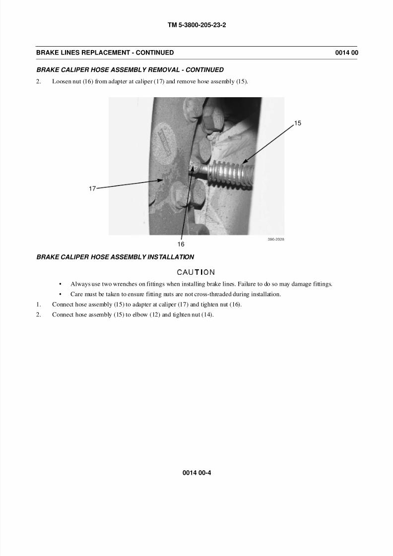
8/14/2019 TM 5-3800-205-23-2 MODEL 613CS
http://slidepdf.com/reader/full/tm-5-3800-205-23-2-model-613cs 86/276
TM 5-3800-205-23-2
0014 00-4
BRAKE LINES REPLACEMENT - CONTINUED 0014 00
BRAKE CALIPER HOSE ASSEMBLY REMOVAL - CONTINUED
2. Loosen nut (16) from adapter at caliper (17) and remove hose assembly (15).
BRAKE CALIPER HOSE ASSEMBLY INSTALLATION
CAUTION
• Always use two wrenches on fittings when installing brake lines. Failure to do so may damage fittings.
• Care must be taken to ensure fitting nuts are not cross-threaded during installation.
1. Connect hose assembly (15) to adapter at caliper (17) and tighten nut (16).
2. Connect hose assembly (15) to elbow (12) and tighten nut (14).
15
16
17
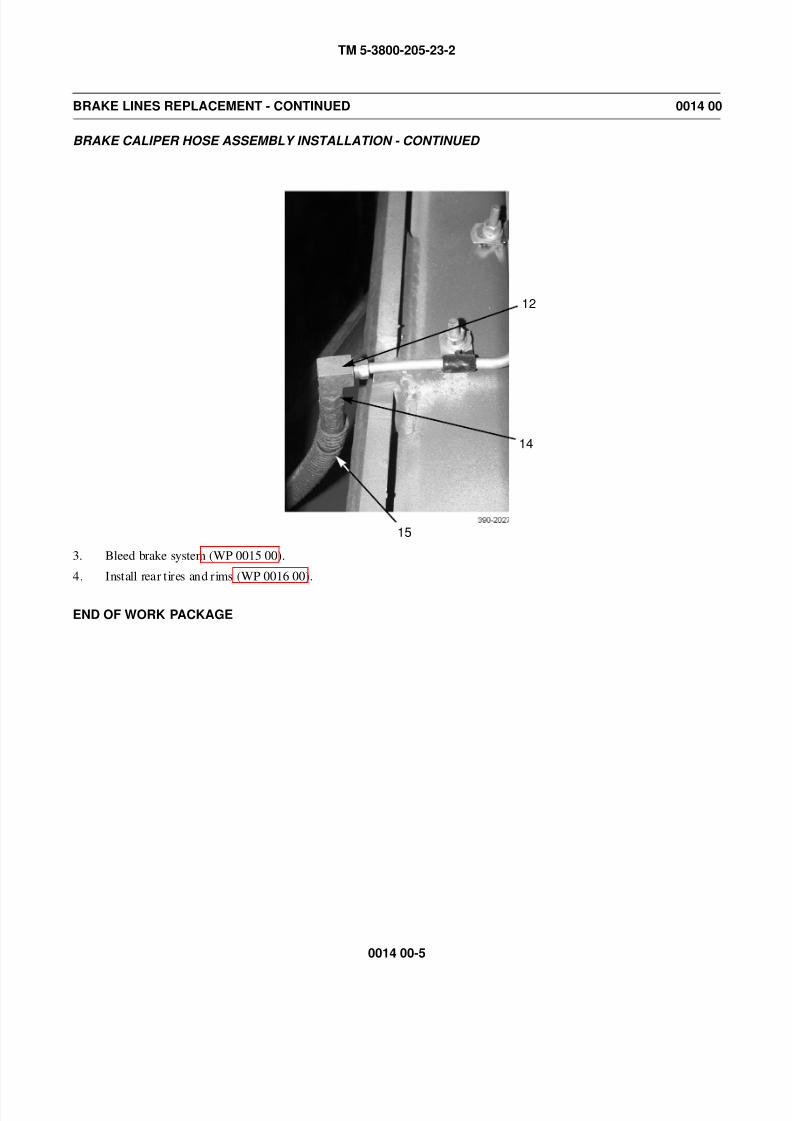
8/14/2019 TM 5-3800-205-23-2 MODEL 613CS
http://slidepdf.com/reader/full/tm-5-3800-205-23-2-model-613cs 87/276
TM 5-3800-205-23-2
0014 00-5
BRAKE LINES REPLACEMENT - CONTINUED 0014 00
BRAKE CALIPER HOSE ASSEMBLY INSTALLATION - CONTINUED
3. Bleed brake system (WP 0015 00).
4. Install rear tires and rims (WP 0016 00).
END OF WORK PACKAGE
12
14
15

8/14/2019 TM 5-3800-205-23-2 MODEL 613CS
http://slidepdf.com/reader/full/tm-5-3800-205-23-2-model-613cs 88/276
TM 5-3800-205-23-2
0014 00-6
This Page Intentionally Left Blank.
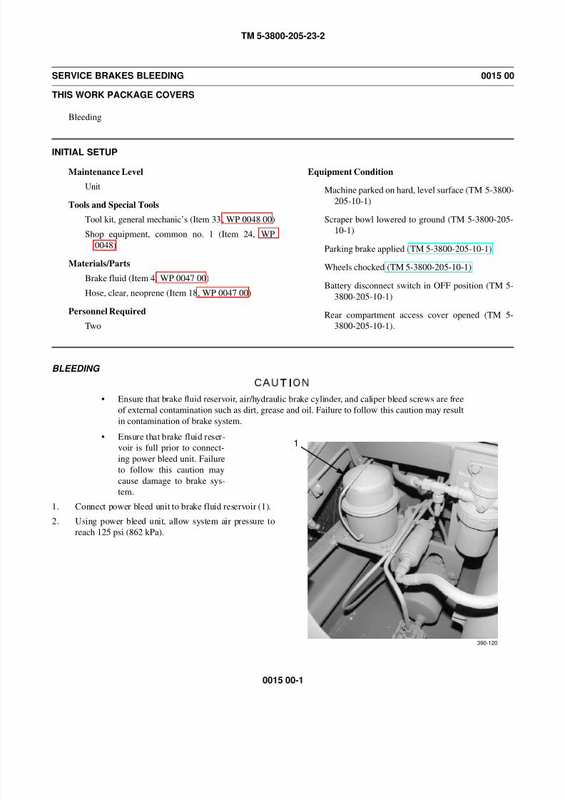
8/14/2019 TM 5-3800-205-23-2 MODEL 613CS
http://slidepdf.com/reader/full/tm-5-3800-205-23-2-model-613cs 89/276
TM 5-3800-205-23-2
0015 00-1
SERVICE BRAKES BLEEDING 0015 00
THIS WORK PACKAGE COVERS
Bleeding
INITIAL SETUP
Maintenance Level
Unit
Tools and Special Tools
Tool kit, general mechanic’s (Item 33, WP 0048 00)
Shop equipment, common no. 1 (Item 24, WP
0048)
Materials/Parts
Brake fluid (Item 4, WP 0047 00)Hose, clear, neoprene (Item 18, WP 0047 00)
Personnel Required
Two
Equipment Condition
Machine parked on hard, level surface (TM 5-3800-
205-10-1)
Scraper bowl lowered to ground (TM 5-3800-205-
10-1)
Parking brake applied (TM 5-3800-205-10-1)
Wheels chocked (TM 5-3800-205-10-1)
Battery disconnect switch in OFF position (TM 5-
3800-205-10-1)
Rear compartment access cover opened (TM 5-
3800-205-10-1).
BLEEDING
CAUTION
• Ensure that brake fluid reservoir, air/hydraulic brake cylinder, and caliper bleed screws are free
of external contamination such as dirt, grease and oil. Failure to follow this caution may result
in contamination of brake system.
• Ensure that brake fluid reser-
voir is full prior to connect-
ing power bleed unit. Failure
to follow this caution may
cause damage to brake sys-
tem.
1. Connect power bleed unit to brake fluid reservoir (1).
2. Using power bleed unit, allow system air pressure to
reach 125 psi (862 kPa).
390-012
1
390-120
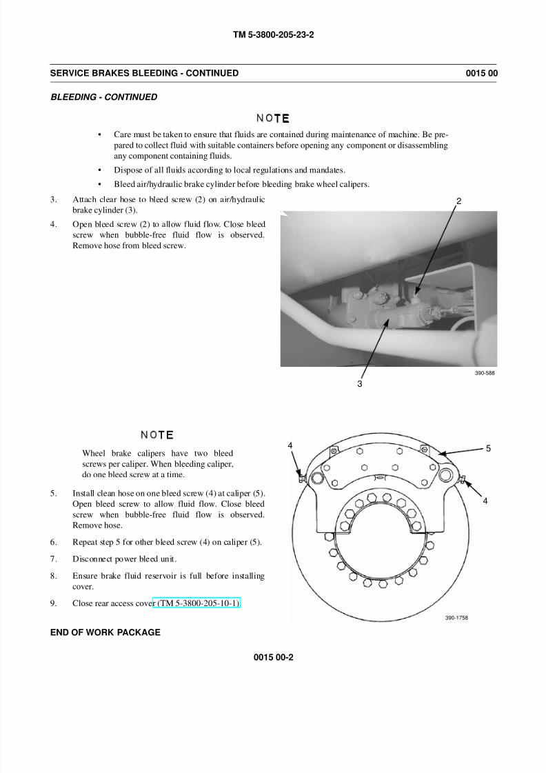
8/14/2019 TM 5-3800-205-23-2 MODEL 613CS
http://slidepdf.com/reader/full/tm-5-3800-205-23-2-model-613cs 90/276
TM 5-3800-205-23-2
0015 00-2
SERVICE BRAKES BLEEDING - CONTINUED 0015 00
BLEEDING - CONTINUED
NOTE
• Care must be taken to ensure that fluids are contained during maintenance of machine. Be pre-pared to collect fluid with suitable containers before opening any component or disassembling
any component containing fluids.
• Dispose of all fluids according to local regulations and mandates.
• Bleed air/hydraulic brake cylinder before bleeding brake wheel calipers.
3. Attach clear hose to bleed screw (2) on air/hydraulic
brake cylinder (3).
4. Open bleed screw (2) to allow fluid flow. Close bleed
screw when bubble-free fluid flow is observed.
Remove hose from bleed screw.
NOTE
Wheel brake calipers have two bleed
screws per caliper. When bleeding caliper,
do one bleed screw at a time.
5. Install clean hose on one bleed screw (4) at caliper (5).
Open bleed screw to allow fluid flow. Close bleed
screw when bubble-free fluid flow is observed.
Remove hose.
6. Repeat step 5 for other bleed screw (4) on caliper (5).
7. Disconnect power bleed unit.
8. Ensure brake fluid reservoir is full before installing
cover.
9. Close rear access cover (TM 5-3800-205-10-1).
END OF WORK PACKAGE
390-588
3
2
4
390-1758
5
4
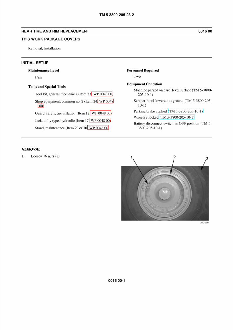
8/14/2019 TM 5-3800-205-23-2 MODEL 613CS
http://slidepdf.com/reader/full/tm-5-3800-205-23-2-model-613cs 91/276
TM 5-3800-205-23-2
0016 00-1
REAR TIRE AND RIM REPLACEMENT 0016 00
THIS WORK PACKAGE COVERS
Removal, Installation
INITIAL SETUP
Maintenance Level
Unit
Tools and Special Tools
Tool kit, general mechanic’s (Item 33, WP 0048 00)
Shop equipment, common no. 2 (Item 24, WP 0048
00)
Guard, safety, tire inflation (Item 12, WP 0048 00)
Jack, dolly type, hydraulic (Item 17, WP 0048 00)
Stand, maintenance (Item 29 or 30, WP 0048 00)
Personnel Required
Two
Equipment Condition
Machine parked on hard, level surface (TM 5-3800-
205-10-1)
Scraper bowl lowered to ground (TM 5-3800-205-
10-1)
Parking brake applied (TM 5-3800-205-10-1)
Wheels chocked (TM 5-3800-205-10-1)
Battery disconnect switch in OFF position (TM 5-
3800-205-10-1)
REMOVAL
1. Loosen 16 nuts (1). 21 3
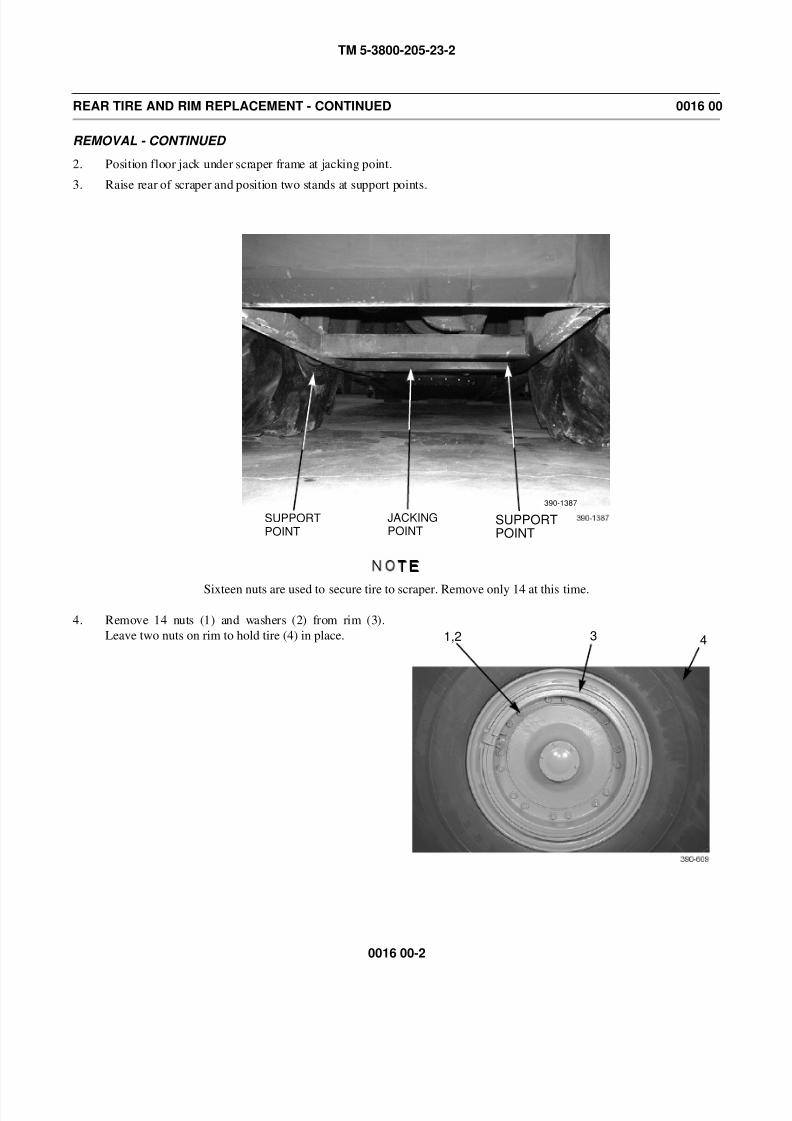
8/14/2019 TM 5-3800-205-23-2 MODEL 613CS
http://slidepdf.com/reader/full/tm-5-3800-205-23-2-model-613cs 92/276
TM 5-3800-205-23-2
0016 00-2
REAR TIRE AND RIM REPLACEMENT - CONTINUED 0016 00
REMOVAL - CONTINUED
2. Position floor jack under scraper frame at jacking point.
3. Raise rear of scraper and position two stands at support points.
NOTE
Sixteen nuts are used to secure tire to scraper. Remove only 14 at this time.
4. Remove 14 nuts (1) and washers (2) from rim (3).
Leave two nuts on rim to hold tire (4) in place.
SUPPORTPOINT
SUPPORTPOINT
JACKINGPOINT
390-1387
31,2 4
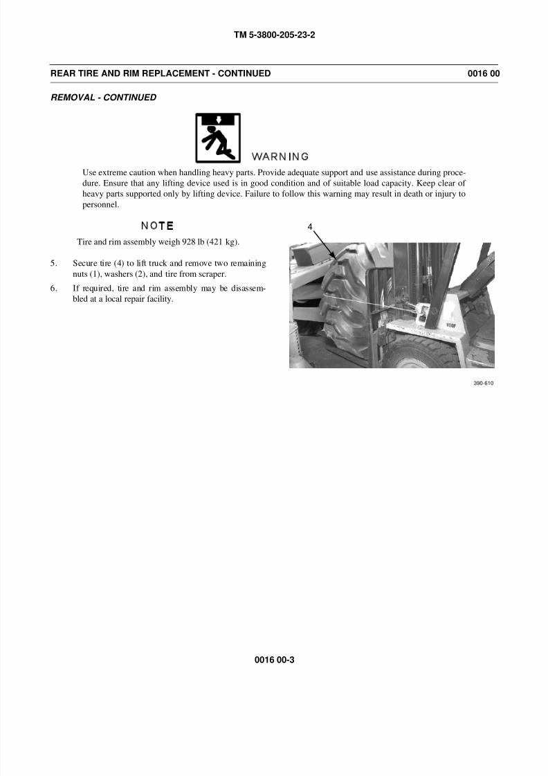
8/14/2019 TM 5-3800-205-23-2 MODEL 613CS
http://slidepdf.com/reader/full/tm-5-3800-205-23-2-model-613cs 93/276
TM 5-3800-205-23-2
0016 00-3
REAR TIRE AND RIM REPLACEMENT - CONTINUED 0016 00
REMOVAL - CONTINUED
WARNING
Use extreme caution when handling heavy parts. Provide adequate support and use assistance during proce-
dure. Ensure that any lifting device used is in good condition and of suitable load capacity. Keep clear of
heavy parts supported only by lifting device. Failure to follow this warning may result in death or injury to
personnel.
NOTE
Tire and rim assembly weigh 928 lb (421 kg).
5. Secure tire (4) to lift truck and remove two remaining
nuts (1), washers (2), and tire from scraper.
6. If required, tire and rim assembly may be disassem-
bled at a local repair facility.
4
390-610

8/14/2019 TM 5-3800-205-23-2 MODEL 613CS
http://slidepdf.com/reader/full/tm-5-3800-205-23-2-model-613cs 94/276
TM 5-3800-205-23-2
0016 00-4
REAR TIRE AND RIM REPLACEMENT - CONTINUED 0016 00
INSTALLATION
WARNING
Use extreme caution when handling heavy parts. Provide adequate support and use assistance during proce-
dure. Ensure that any lifting device used is in good condition and of suitable load capacity. Keep clear of
heavy parts supported only by lifting device. Failure to follow this warning may result in death or injury to
personnel.
NOTE
Tire and rim assembly weigh 928 lb (421 kg).
1. Position tire (4) on scraper.
2. Install two washers (2) and nuts (1) on rim (3) and remove lift truck from tire (4).
3. Install 14 remaining washers (2) and nuts (1) on rim (3). Tighten nuts to 105 lb-ft (140 Nm).
4. Tighten nuts (1) to 370 lb-ft (500 Nm).
5. Remove two stands and use floor jack to lower scraper to ground.
WARNING
Use of a tire inflation safety cage is required if tire has inflation pressure of 36 psi (248 kPa) or less. Failure
to do so may result in injury or death to personnel.
6. Check tire pressure and add air as required (TM 5-3800-205-10-1).
END OF WORK PACKAGE
431,2
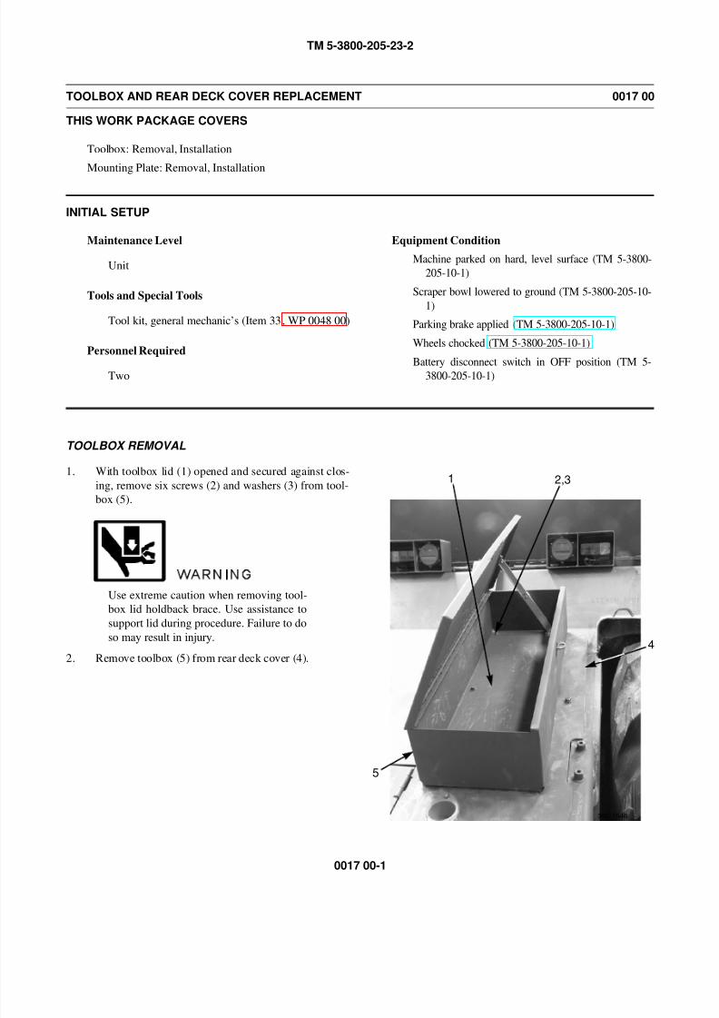
8/14/2019 TM 5-3800-205-23-2 MODEL 613CS
http://slidepdf.com/reader/full/tm-5-3800-205-23-2-model-613cs 95/276
TM 5-3800-205-23-2
0017 00-1
TOOLBOX AND REAR DECK COVER REPLACEMENT 0017 00
THIS WORK PACKAGE COVERS
Toolbox: Removal, Installation
Mounting Plate: Removal, Installation
INITIAL SETUP
Maintenance Level
Unit
Tools and Special Tools
Tool kit, general mechanic’s (Item 33, WP 0048 00)
Personnel Required
Two
Equipment Condition
Machine parked on hard, level surface (TM 5-3800-
205-10-1)
Scraper bowl lowered to ground (TM 5-3800-205-10-
1)
Parking brake applied (TM 5-3800-205-10-1)
Wheels chocked (TM 5-3800-205-10-1)
Battery disconnect switch in OFF position (TM 5-
3800-205-10-1)
TOOLBOX REMOVAL
1. With toolbox lid (1) opened and secured against clos-
ing, remove six screws (2) and washers (3) from tool-
box (5).
WARNING
Use extreme caution when removing tool-
box lid holdback brace. Use assistance to
support lid during procedure. Failure to do
so may result in injury.
2. Remove toolbox (5) from rear deck cover (4).
1 2,3
4
5
390-1546
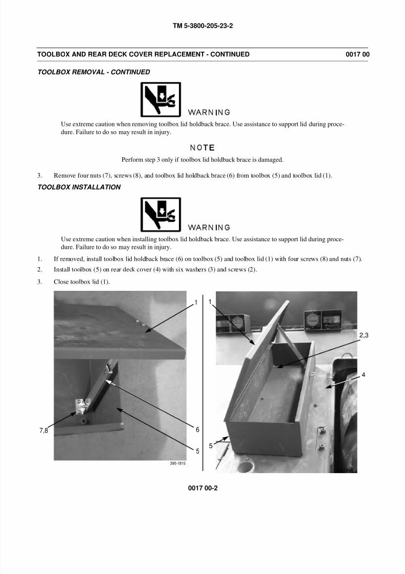
8/14/2019 TM 5-3800-205-23-2 MODEL 613CS
http://slidepdf.com/reader/full/tm-5-3800-205-23-2-model-613cs 96/276
TM 5-3800-205-23-2
0017 00-2
TOOLBOX AND REAR DECK COVER REPLACEMENT - CONTINUED 0017 00
TOOLBOX REMOVAL - CONTINUED
WARNING
Use extreme caution when removing toolbox lid holdback brace. Use assistance to support lid during proce-
dure. Failure to do so may result in injury.
NOTE
Perform step 3 only if toolbox lid holdback brace is damaged.
3. Remove four nuts (7), screws (8), and toolbox lid holdback brace (6) from toolbox (5) and toolbox lid (1).
TOOLBOX INSTALLATION
WARNING
Use extreme caution when installing toolbox lid holdback brace. Use assistance to support lid during proce-
dure. Failure to do so may result in injury.
1. If removed, install toolbox lid holdback brace (6) on toolbox (5) and toolbox lid (1) with four screws (8) and nuts (7).
2. Install toolbox (5) on rear deck cover (4) with six washers (3) and screws (2).
3. Close toolbox lid (1).
1
67,8
390-1815
1
2,3
5
390-1546
5
4
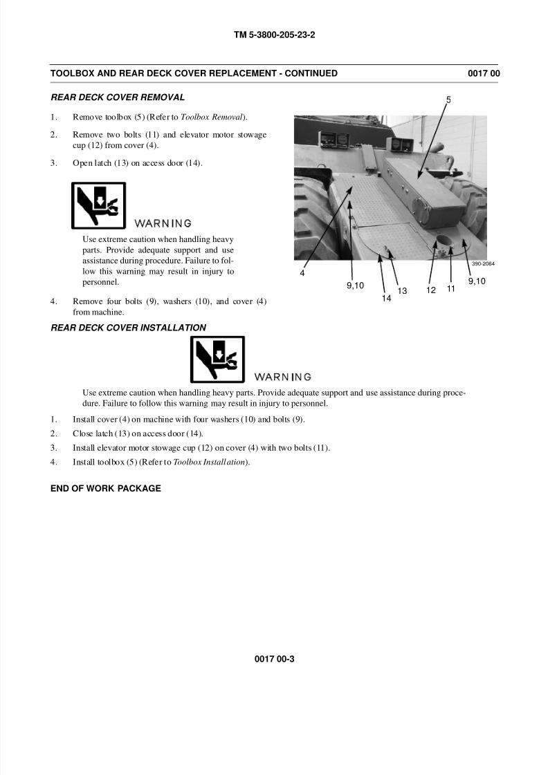
8/14/2019 TM 5-3800-205-23-2 MODEL 613CS
http://slidepdf.com/reader/full/tm-5-3800-205-23-2-model-613cs 97/276
TM 5-3800-205-23-2
0017 00-3
TOOLBOX AND REAR DECK COVER REPLACEMENT - CONTINUED 0017 00
REAR DECK COVER REMOVAL
1. Remove toolbox (5) (Refer to Toolbox Removal).
2. Remove two bolts (11) and elevator motor stowagecup (12) from cover (4).
3. Open latch (13) on access door (14).
WARNING
Use extreme caution when handling heavy
parts. Provide adequate support and use
assistance during procedure. Failure to fol-
low this warning may result in injury topersonnel.
4. Remove four bolts (9), washers (10), and cover (4)
from machine.
REAR DECK COVER INSTALLATION
WARNING
Use extreme caution when handling heavy parts. Provide adequate support and use assistance during proce-
dure. Failure to follow this warning may result in injury to personnel.1. Install cover (4) on machine with four washers (10) and bolts (9).
2. Close latch (13) on access door (14).
3. Install elevator motor stowage cup (12) on cover (4) with two bolts (11).
4. Install toolbox (5) (Refer to Toolbox Installation).
END OF WORK PACKAGE
4
5
9,10
390-2064
9,10111213
14

8/14/2019 TM 5-3800-205-23-2 MODEL 613CS
http://slidepdf.com/reader/full/tm-5-3800-205-23-2-model-613cs 98/276
TM 5-3800-205-23-2
0017 00-4
This Page Intentionally Left Blank.
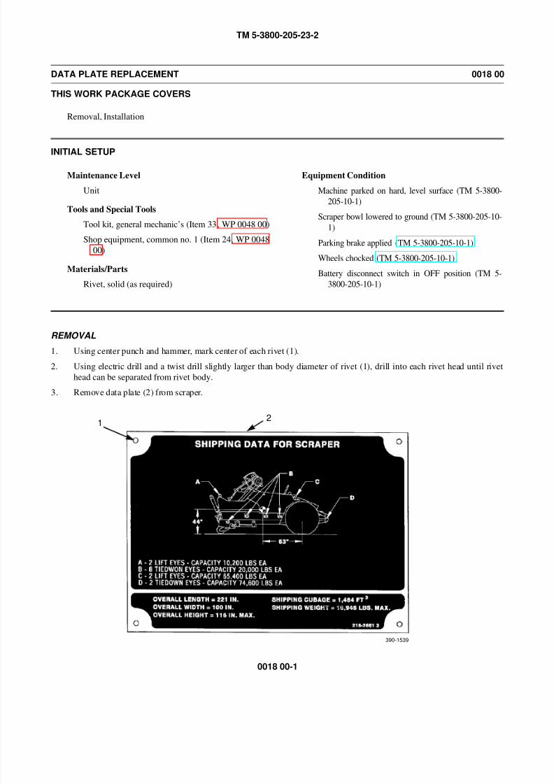
8/14/2019 TM 5-3800-205-23-2 MODEL 613CS
http://slidepdf.com/reader/full/tm-5-3800-205-23-2-model-613cs 99/276
TM 5-3800-205-23-2
0018 00-1
DATA PLATE REPLACEMENT 0018 00
THIS WORK PACKAGE COVERS
Removal, Installation
INITIAL SETUP
Maintenance Level
Unit
Tools and Special Tools
Tool kit, general mechanic’s (Item 33, WP 0048 00)
Shop equipment, common no. 1 (Item 24, WP 0048
00)
Materials/Parts
Rivet, solid (as required)
Equipment Condition
Machine parked on hard, level surface (TM 5-3800-
205-10-1)
Scraper bowl lowered to ground (TM 5-3800-205-10-
1)
Parking brake applied (TM 5-3800-205-10-1)
Wheels chocked (TM 5-3800-205-10-1)
Battery disconnect switch in OFF position (TM 5-3800-205-10-1)
REMOVAL
1. Using center punch and hammer, mark center of each rivet (1).
2. Using electric drill and a twist drill slightly larger than body diameter of rivet (1), drill into each rivet head until rivet
head can be separated from rivet body.
3. Remove data plate (2) from scraper.
12
390-1539
390-1539
8/14/2019 TM 5-3800-205-23-2 MODEL 613CS
http://slidepdf.com/reader/full/tm-5-3800-205-23-2-model-613cs 100/276
TM 5-3800-205-23-2
0018 00-2
DATA PLATE REPLACEMENT - CONTINUED 0018 00
REMOVAL - CONTINUED
CAUTION
DO NOT drill any deeper than necessary to remove rivet body. Failure to follow this caution will result in
damage to scraper.
4. Using twist drill the same diameter as rivet (1) body, remove rivet body from scraper.
INSTALLATION
Install data plate (2) on scraper with new rivets (1).
END OF WORK PACKAGE
8/14/2019 TM 5-3800-205-23-2 MODEL 613CS
http://slidepdf.com/reader/full/tm-5-3800-205-23-2-model-613cs 101/276
TM 5-3800-205-23-2
0019 00-1
ELEVATOR MOTOR REPLACEMENT 0019 00
THIS WORK PACKAGE COVERS
Removal, Installation
INITIAL SETUP
Maintenance Level
Unit
Tools and Special Tools
Tool kit, general mechanic’s (Item 33, WP 0048 00)
Sling, nylon (Item 27, WP 0048 00)
Materials/Parts
Cap set, protective (Item 5, WP 0047 00)
Rag, wiping (Item 31, WP 0047 00)
Tag, marker (Item 39, WP 0047 00)
Personnel Required
Two
References
TM 5-3800-205-23-1
Equipment Condition
Machine parked on hard, level surface (TM 5-3800-
205-10-1)
Scraper bowl lowered to ground (TM 5-3800-205-10-
1)
Parking brake applied (TM 5-3800-205-10-1)
Wheels chocked (TM 5-3800-205-10-1)
Battery disconnect switch in OFF position (TM 5-
3800-205-10-1)
WARNING
• At operating temperature hydraulic oil is hot. Allow hydraulic oil to cool before disconnecting
any hydraulic lines. Failure to do so could result in injury.
• Hydraulic oil is very slippery. Immediately wipe up any spills. Failure to follow this warning
may result in injury to personnel.
CAUTION
Cap hoses to prevent fluid loss and contamination of fuel system.
NOTE
• Tag hoses to aid in installation.
• Care must be taken to ensure that fluids are contained during performance of inspection, main-
tenance, testing, adjusting and repair of the machine. Be prepared to collect fluid with suitable
containers before opening any compartment or disassembling any component containing flu-
ids.
• Dispose of all fluids according to local regulations and mandates.

8/14/2019 TM 5-3800-205-23-2 MODEL 613CS
http://slidepdf.com/reader/full/tm-5-3800-205-23-2-model-613cs 102/276
TM 5-3800-205-23-2
0019 00-2
ELEVATOR MOTOR REPLACEMENT - CONTINUED 0019 00
REMOVAL
1. Relieve hydraulic system pressure (to facilitate disconnection and connection of hoses) by moving control levers
through all positions (TM 5-3800-205-10-1).
2. Disconnect hydraulic hose quick-disconnects (1, 5, and 7) from elevator motor (4).
3. Position nylon sling and suitable lifting device on elevator motor (4).
WARNING
Use extreme caution when handling heavy parts. Provide adequate support and use assistance during proce-
dure. Ensure that any lifting device used is in good condition and of suitable lift capacity. Keep clear of
heavy parts supported only by lifting device. Failure to follow this warning may result in death or injury to
personnel.
NOTE
Elevator motor weighs 65 lb (30 kg).
4. With assistance, remove two bolts (2), washers (3), and elevator motor (4) from elevator drive speed reducer (6).
6
5
1 2,3 4
7
8/14/2019 TM 5-3800-205-23-2 MODEL 613CS
http://slidepdf.com/reader/full/tm-5-3800-205-23-2-model-613cs 103/276
TM 5-3800-205-23-2
0019 00-3
ELEVATOR MOTOR REPLACEMENT - CONTINUED 0019 00
INSTALLATION
WARNING
Use extreme caution when handling heavy parts. Provide adequate support and use assistance during proce-
dure. Ensure that any lifting device used is in good condition and of suitable lift capacity. Keep clear of
heavy parts supported only by lifting device. Failure to follow this warning may result in death or injury to
personnel.
NOTE
Elevator motor weighs 65 lb (30 kg).
1. Position nylon sling and suitable lifting device on elevator motor (4).
2. Install elevator motor (4) on elevator speed reducer (6) with two washers (3) and bolts (2).
3. Connect hydraulic hose quick-disconnects (1, 5, and 7) to elevator motor (4).
4. Check level of oil in speed reducer and add as needed. Refer to PMCS in TM 5-3800-205-23-1.
END OF WORK PACKAGE

8/14/2019 TM 5-3800-205-23-2 MODEL 613CS
http://slidepdf.com/reader/full/tm-5-3800-205-23-2-model-613cs 104/276
TM 5-3800-205-23-2
0019 00-4
This Page Intentionally Left Blank.
8/14/2019 TM 5-3800-205-23-2 MODEL 613CS
http://slidepdf.com/reader/full/tm-5-3800-205-23-2-model-613cs 105/276
TM 5-3800-205-23-2
0020 00-1
HYDRAULIC LINES AND FITTINGS REPLACEMENT 0020 00
THIS WORK PACKAGE COVERS
Quick Disconnect Coupling: Removal, Installation
Hydraulic Hose: Removal, Installation
Hydraulic Tube: Removal, Installation
INITIAL SETUP
Maintenance Level
Unit
Tools and Special Tools
Tool kit, general mechanic’s (Item 33, WP 0048 00)
Shop equipment, common no. 1 (Item 24, WP 0048
00)
Materials/Parts
Cap set, protective (Item 5, WP 0047 00)
Oil, lubricating (Item 24 or 29, WP 0047 00)
Materials/Parts - Continued
Rag, wiping (Item 31, WP 0047 00)
Tag, marker (Item 39, WP 0047 00)
O-ring (as required)
References
WP 0009 00
Equipment Condition
Hydraulic tank drained (all except quick disconnect
hoses) (TM 5-3800-205-23-1, WP 0010 00)
WARNING
• DO NOT disconnect or remove any hydraulic system line or fitting unless engine is shut down
and hydraulic system pressure has been relieved. Tighten all connections before applying pres-
sure. Escaping hydraulic fluid under pressure can penetrate the skin, causing serious injury.
• At operating temperature, hydraulic oil is hot. Allow hydraulic oil to cool before disconnecting
any hydraulic lines. Failure to do so could result in injury.
• Hydraulic fluid is very slippery. Immediately wipe up any spills. Failure to follow this warning
may result in injury to personnel.
CAUTION
Wipe area clean around all hydraulic connections prior to disconnecting. Cap all openings after disconnect-
ing. Contamination of hydraulic system could result in equipment failure.
NOTE
Tag hydraulic lines to aid in installation.
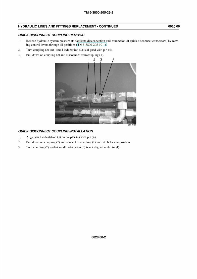
8/14/2019 TM 5-3800-205-23-2 MODEL 613CS
http://slidepdf.com/reader/full/tm-5-3800-205-23-2-model-613cs 106/276
TM 5-3800-205-23-2
0020 00-2
HYDRAULIC LINES AND FITTINGS REPLACEMENT - CONTINUED 0020 00
QUICK DISCONNECT COUPLING REMOVAL
1. Relieve hydraulic system pressure (to facilitate disconnection and connection of quick disconnect connectors) by mov-
ing control levers through all positions (TM 5-3800-205-10-1).
2. Turn coupling (2) until small indentation (3) is aligned with pin (4).
3. Pull down on coupling (2) and disconnect from coupling (1).
QUICK DISCONNECT COUPLING INSTALLATION
1. Align small indentation (3) on coupler (2) with pin (4).
2. Pull down on coupling (2) and connect to coupling (1) until it clicks into position.
3. Turn coupling (2) so that small indentation (3) is not aligned with pin (4).
1 2 3
390-1490
4
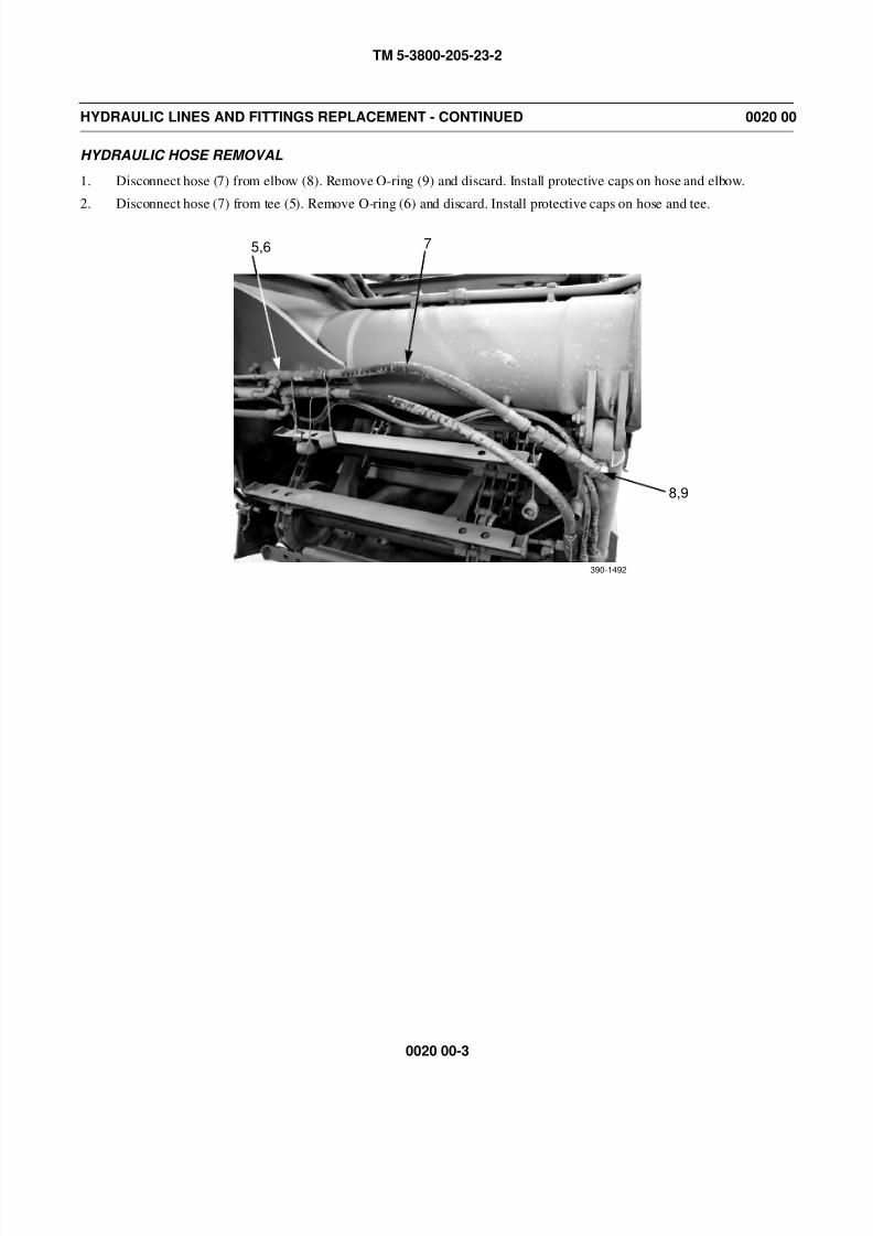
8/14/2019 TM 5-3800-205-23-2 MODEL 613CS
http://slidepdf.com/reader/full/tm-5-3800-205-23-2-model-613cs 107/276
TM 5-3800-205-23-2
0020 00-3
HYDRAULIC LINES AND FITTINGS REPLACEMENT - CONTINUED 0020 00
HYDRAULIC HOSE REMOVAL
1. Disconnect hose (7) from elbow (8). Remove O-ring (9) and discard. Install protective caps on hose and elbow.
2. Disconnect hose (7) from tee (5). Remove O-ring (6) and discard. Install protective caps on hose and tee.
5,6 7
8,9
390-1492
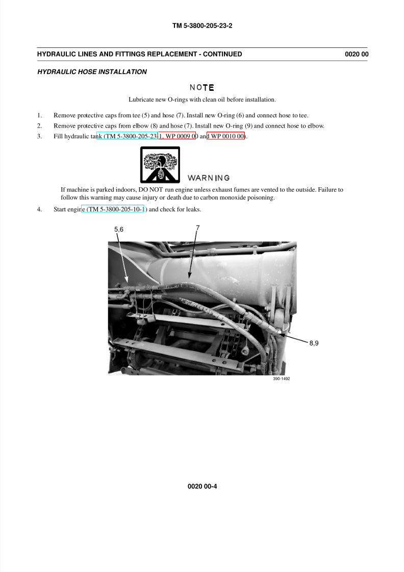
8/14/2019 TM 5-3800-205-23-2 MODEL 613CS
http://slidepdf.com/reader/full/tm-5-3800-205-23-2-model-613cs 108/276
TM 5-3800-205-23-2
0020 00-4
HYDRAULIC LINES AND FITTINGS REPLACEMENT - CONTINUED 0020 00
HYDRAULIC HOSE INSTALLATION
NOTE
Lubricate new O-rings with clean oil before installation.
1. Remove protective caps from tee (5) and hose (7). Install new O-ring (6) and connect hose to tee.
2. Remove protective caps from elbow (8) and hose (7). Install new O-ring (9) and connect hose to elbow.
3. Fill hydraulic tank (TM 5-3800-205-23-1, WP 0009 00 and WP 0010 00).
WARNING
If machine is parked indoors, DO NOT run engine unless exhaust fumes are vented to the outside. Failure to
follow this warning may cause injury or death due to carbon monoxide poisoning.4. Start engine (TM 5-3800-205-10-1) and check for leaks.
5,6 7
8,9
390-1492

8/14/2019 TM 5-3800-205-23-2 MODEL 613CS
http://slidepdf.com/reader/full/tm-5-3800-205-23-2-model-613cs 109/276
TM 5-3800-205-23-2
0020 00-5
HYDRAULIC LINES AND FITTINGS REPLACEMENT - CONTINUED 0020 00
HYDRAULIC TUBE REMOVAL
CAUTION
Use two wrench method when disconnecting non-quick disconnect connections to prevent damage to fit-tings.
NOTE
Hydraulic system uses several different style clamps. A four-bolt clamp is shown.
1. Disconnect hose (10) from tube (11). Remove O-ring (11) and discard. Install protective caps on hose and tube.
2. Remove four bolts (13) from front half of clamp (14).
3. Repeat steps 1 and 2 to remove the other end of tube (11). Remove tube from machine.
10 11,12
1314390-1495
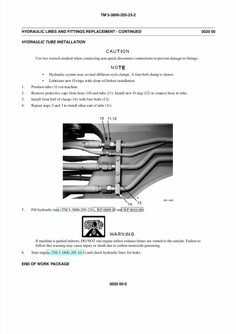
8/14/2019 TM 5-3800-205-23-2 MODEL 613CS
http://slidepdf.com/reader/full/tm-5-3800-205-23-2-model-613cs 110/276
TM 5-3800-205-23-2
0020 00-6
HYDRAULIC LINES AND FITTINGS REPLACEMENT - CONTINUED 0020 00
HYDRAULIC TUBE INSTALLATION
CAUTION
Use two wrench method when connecting non-quick disconnect connections to prevent damage to fittings.
NOTE
• Hydraulic system uses several different style clamps. A four-bolt clamp is shown.
• Lubricate new O-rings with clean oil before installation.
1. Position tube (11) on machine.
2. Remove protective caps from hose (10) and tube (11). Install new O-ring (12) to connect hose to tube.
3. Install front half of clamp (14) with four bolts (13).
4. Repeat steps 2 and 3 to install other end of tube (11).
5. Fill hydraulic tank (TM 5-3800-205-23-1, WP 0009 00 and WP 0010 00).
WARNING
If machine is parked indoors, DO NOT run engine unless exhaust fumes are vented to the outside. Failure to
follow this warning may cause injury or death due to carbon monoxide poisoning.
6. Start engine (TM 5-3800-205-10-1) and check hydraulic lines for leaks.
END OF WORK PACKAGE
10 11,12
1314390-1495
8/14/2019 TM 5-3800-205-23-2 MODEL 613CS
http://slidepdf.com/reader/full/tm-5-3800-205-23-2-model-613cs 111/276
TM 5-3800-205-23-2
0021 00-1
CHECK VALVE AND LIFT CYLINDER REPLACEMENT 0021 00
THIS WORK PACKAGE COVERS
Check Valve: Removal, Installation
Lift Cylinder: Removal, Installation
INITIAL SETUP
Maintenance Level
Unit
Tools and Special Tools
Tool kit, general mechanic’s (Item 33, WP 0048 00)
Sling, nylon (Item 27, WP 0048 00)
Materials/Parts
Cap set, protective (Item 5, WP 0047 00)
Compound, antiseize (Item 8, WP 0047 00)
Oil, lubricating (Item 24 or 29, WP 0047 00)
Rag, wiping (Item 31, WP 0047 00)
Tag, marker (Item 39, WP 0047 00)
Seal, O-ring (3)
Personnel Required
Two
References
TM 5-3800-205-23-1
Equipment Condition
Machine parked on hard, level surface (TM 5-3800-
205-10-1)
Scraper bowl lowered to ground TM 5-3800-205-
10-1)Parking brake engaged (TM 5-3800-205-10-1)
Engine off (TM 5-3800-205-10-1)
Wheels chocked (TM 5-3800-205-10-1)
Battery disconnect switch in OFF position (TM 5-
3800-205-10-1)
WARNING
• Do NOT disconnect or remove any hydraulic system line or fitting unless hydraulic system pressure has
been relieved. Tighten all connections before applying pressure. Escaping hydraulic fluid under pres-
sure can penetrate the skin, causing serious injury.
• At operating temperature hydraulic oil is hot. Allow hydraulic oil to cool before disconnecting any
hydraulics. Failure to do so could result in injury.
CAUTION
Cap all hoses and openings to prevent fluid loss and contamination of oil system.
NOTE
• Tag all hoses to aid in installation.
• Care must be taken to ensure that fluids are contained during performance of inspection, maintenance,
testing, adjusting, and repair of the machine. Be prepared to collect the fluid with suitable containers
before opening any compartment or disassembling any component containing fluids.
• Dispose of all fluids according to local regulations and mandates.
• Right and left check valves and lift cylinders are replaced the same way. Left-side check valve and lift
cylinder is shown.
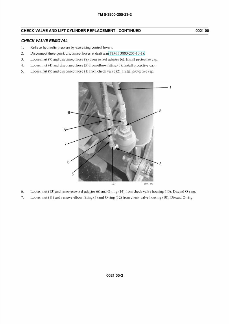
8/14/2019 TM 5-3800-205-23-2 MODEL 613CS
http://slidepdf.com/reader/full/tm-5-3800-205-23-2-model-613cs 112/276
TM 5-3800-205-23-2
0021 00-2
CHECK VALVE AND LIFT CYLINDER REPLACEMENT - CONTINUED 0021 00
CHECK VALVE REMOVAL
1. Relieve hydraulic pressure by exercising control levers.
2. Disconnect three quick disconnect hoses at draft arm (TM 5 3800-205-10-1).
3. Loosen nut (7) and disconnect hose (8) from swivel adapter (6). Install protective cap.
4. Loosen nut (4) and disconnect hose (5) from elbow fitting (3). Install protective cap.
5. Loosen nut (9) and disconnect hose (1) from check valve (2). Install protective cap.
6. Loosen nut (13) and remove swivel adapter (6) and O-ring (14) from check valve housing (10). Discard O-ring.
7. Loosen nut (11) and remove elbow fitting (3) and O-ring (12) from check valve housing (10). Discard O-ring.
2
3
4
5
6
8
9
390-1212
1
7
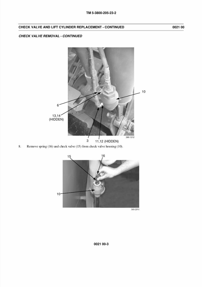
8/14/2019 TM 5-3800-205-23-2 MODEL 613CS
http://slidepdf.com/reader/full/tm-5-3800-205-23-2-model-613cs 113/276
TM 5-3800-205-23-2
0021 00-3
CHECK VALVE AND LIFT CYLINDER REPLACEMENT - CONTINUED 0021 00
CHECK VALVE REMOVAL - CONTINUED
8. Remove spring (16) and check valve (15) from check valve housing (10).
10
11,12 (HIDDEN)3
13,14
6
(HIDDEN)
390-1212
15 16
10
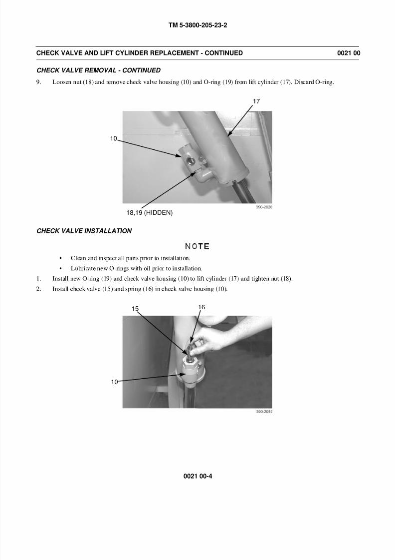
8/14/2019 TM 5-3800-205-23-2 MODEL 613CS
http://slidepdf.com/reader/full/tm-5-3800-205-23-2-model-613cs 114/276
TM 5-3800-205-23-2
0021 00-4
CHECK VALVE AND LIFT CYLINDER REPLACEMENT - CONTINUED 0021 00
CHECK VALVE REMOVAL - CONTINUED
9. Loosen nut (18) and remove check valve housing (10) and O-ring (19) from lift cylinder (17). Discard O-ring.
CHECK VALVE INSTALLATION
NOTE
• Clean and inspect all parts prior to installation.
• Lubricate new O-rings with oil prior to installation.
1. Install new O-ring (19) and check valve housing (10) to lift cylinder (17) and tighten nut (18).
2. Install check valve (15) and spring (16) in check valve housing (10).
17
10
18,19 (HIDDEN)
15 16
10
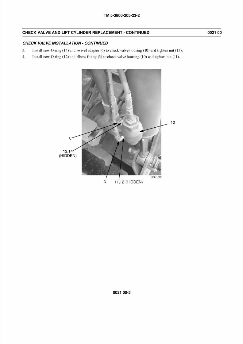
8/14/2019 TM 5-3800-205-23-2 MODEL 613CS
http://slidepdf.com/reader/full/tm-5-3800-205-23-2-model-613cs 115/276
TM 5-3800-205-23-2
0021 00-5
CHECK VALVE AND LIFT CYLINDER REPLACEMENT - CONTINUED 0021 00
CHECK VALVE INSTALLATION - CONTINUED
3. Install new O-ring (14) and swivel adapter (6) to check valve housing (10) and tighten nut (13).
4. Install new O-ring (12) and elbow fitting (3) to check valve housing (10) and tighten nut (11).
10
11,12 (HIDDEN)3
13,14
6
(HIDDEN)
390-1212

8/14/2019 TM 5-3800-205-23-2 MODEL 613CS
http://slidepdf.com/reader/full/tm-5-3800-205-23-2-model-613cs 116/276
TM 5-3800-205-23-2
0021 00-6
CHECK VALVE AND LIFT CYLINDER REPLACEMENT - CONTINUED 0021 00
CHECK VALVE INSTALLATION - CONTINUED
5. Remove protective cap, connect hose (1) to check valve (2), and tighten nut (9).
6. Remove protective cap, connect hose (5) to elbow fitting (3), and tighten nut (4).
7. Remove protective cap, connect hose (8) to swivel adapter (6), and tighten nut (7).
8. Fill hydraulic reservoir with oil (Refer to Unit PMCS in TM 5-3800-205-24-1).
9. Place battery disconnect switch in ON position (TM 5-3800-205-10-1).
10. Operate lift cylinders (TM 5-3800-205-10-1) and check for leaks and proper operation.
LIFT CYLINDER REMOVAL
1. Relieve hydraulic pressure by exercising control levers.
2. Disconnect three quick disconnect hoses at draft arm (TM 5 3800-205-10-1).
3. Loosen nut (7) and disconnect hose (8) from swivel adapter (6). Install protective cap.
4. Loosen nut (4) and disconnect hose (5) from elbow fitting (3). Install protective cap.
5. Loosen nut (9) and disconnect hose (1) from check valve (2). Install protective cap.
6. Loosen nut (13) and remove swivel adapter (6) and O-ring (14) from check valve housing (10). Discard O-ring.
7. Loosen nut (11) and remove elbow fitting (3) and O-ring (12) from check valve housing (10). Discard O-ring.
2
3
4
5
6
7
8
9
390-1212
1
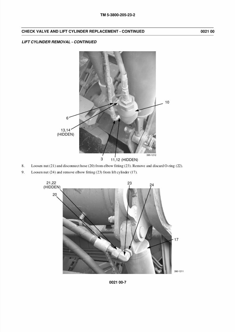
8/14/2019 TM 5-3800-205-23-2 MODEL 613CS
http://slidepdf.com/reader/full/tm-5-3800-205-23-2-model-613cs 117/276
TM 5-3800-205-23-2
0021 00-7
CHECK VALVE AND LIFT CYLINDER REPLACEMENT - CONTINUED 0021 00
LIFT CYLINDER REMOVAL - CONTINUED
8. Loosen nut (21) and disconnect hose (20) from elbow fitting (23). Remove and discard O-ring (22).
9. Loosen nut (24) and remove elbow fitting (23) from lift cylinder (17).
10
11,12 (HIDDEN)3
13,14
6
(HIDDEN)
390-1212
20
21,22 23 24
17
(HIDDEN)
390-1211
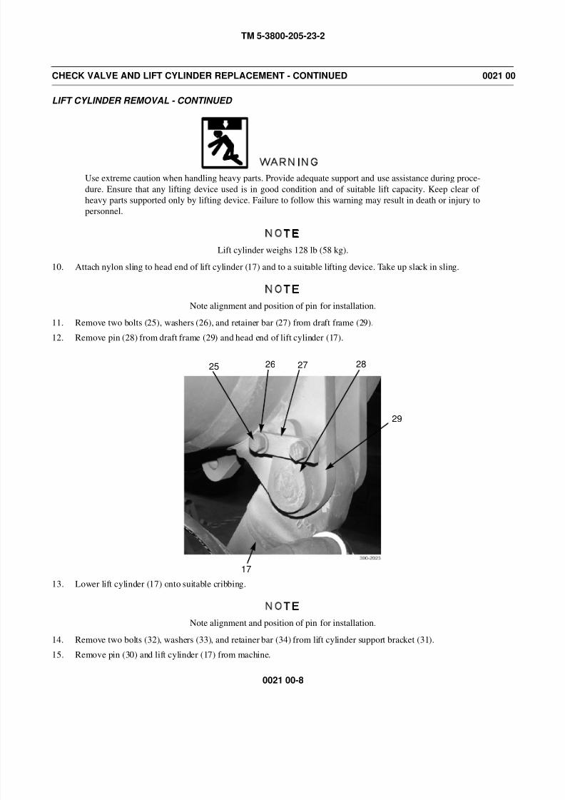
8/14/2019 TM 5-3800-205-23-2 MODEL 613CS
http://slidepdf.com/reader/full/tm-5-3800-205-23-2-model-613cs 118/276
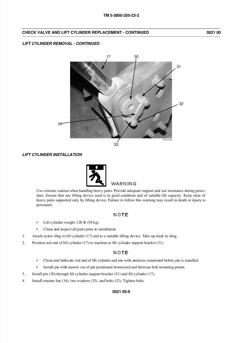
8/14/2019 TM 5-3800-205-23-2 MODEL 613CS
http://slidepdf.com/reader/full/tm-5-3800-205-23-2-model-613cs 119/276
TM 5-3800-205-23-2
0021 00-9
CHECK VALVE AND LIFT CYLINDER REPLACEMENT - CONTINUED 0021 00
LIFT CYLINDER REMOVAL - CONTINUED
LIFT CYLINDER INSTALLATION
WARNING
Use extreme caution when handling heavy parts. Provide adequate support and use assistance during proce-
dure. Ensure that any lifting device used is in good condition and of suitable lift capacity. Keep clear of
heavy parts supported only by lifting device. Failure to follow this warning may result in death or injury to
personnel.
NOTE
• Lift cylinder weighs 128 lb (58 kg).
• Clean and inspect all parts prior to installation.
1. Attach nylon sling to lift cylinder (17) and to a suitable lifting device. Take up slack in sling.
2. Position rod end of lift cylinder (17) to machine at lift cylinder support bracket (31).
NOTE
• Clean and lubricate rod end of lift cylinder and pin with antiseize compound before pin is installed.
• Install pin with narrow ear of pin positioned downward and between bolt mounting points.
3. Install pin (30) through lift cylinder support bracket (31) and lift cylinder (17).
4. Install retainer bar (34), two washers (33), and bolts (32). Tighten bolts.
17 30
31
32
33
34
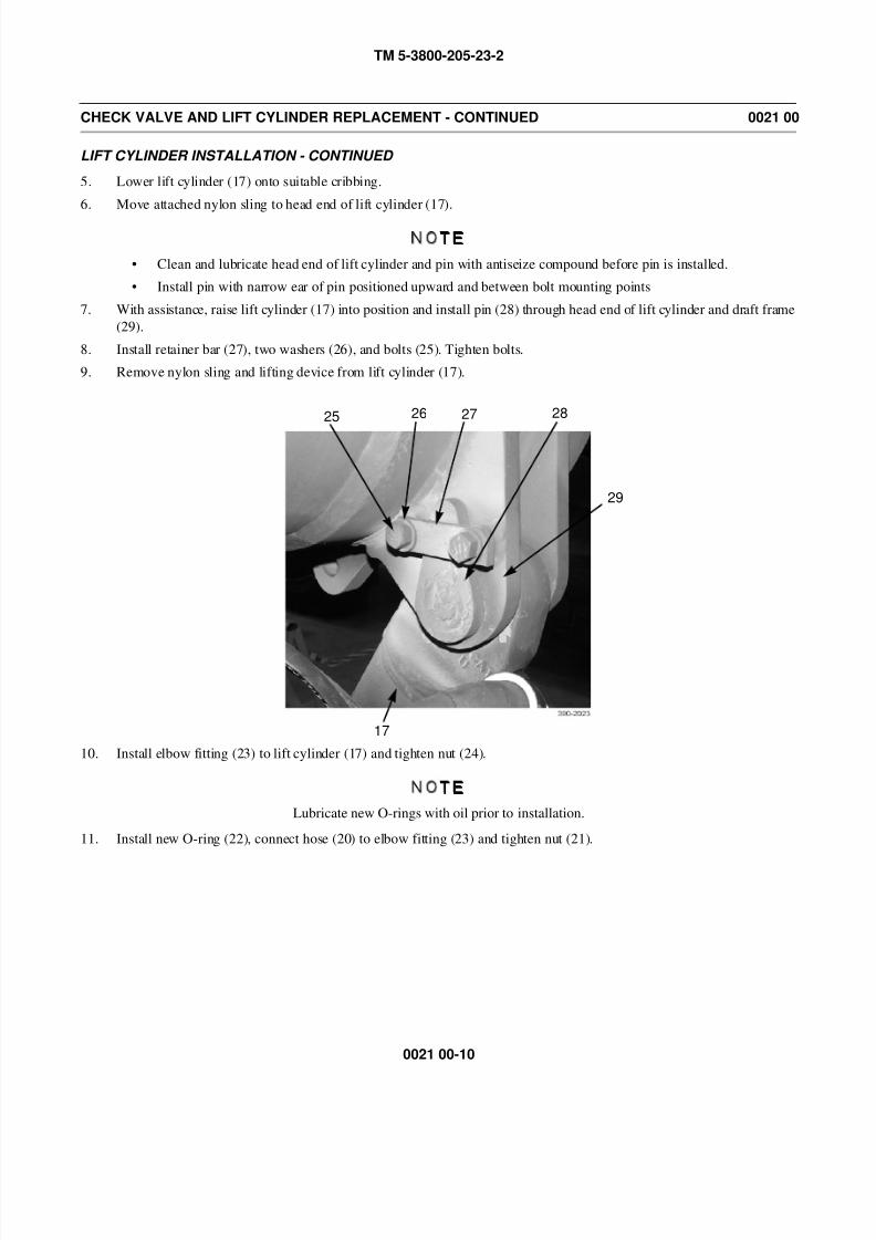
8/14/2019 TM 5-3800-205-23-2 MODEL 613CS
http://slidepdf.com/reader/full/tm-5-3800-205-23-2-model-613cs 120/276
TM 5-3800-205-23-2
0021 00-10
CHECK VALVE AND LIFT CYLINDER REPLACEMENT - CONTINUED 0021 00
LIFT CYLINDER INSTALLATION - CONTINUED
5. Lower lift cylinder (17) onto suitable cribbing.
6. Move attached nylon sling to head end of lift cylinder (17).
NOTE
• Clean and lubricate head end of lift cylinder and pin with antiseize compound before pin is installed.
• Install pin with narrow ear of pin positioned upward and between bolt mounting points
7. With assistance, raise lift cylinder (17) into position and install pin (28) through head end of lift cylinder and draft frame
(29).
8. Install retainer bar (27), two washers (26), and bolts (25). Tighten bolts.
9. Remove nylon sling and lifting device from lift cylinder (17).
10. Install elbow fitting (23) to lift cylinder (17) and tighten nut (24).
NOTE
Lubricate new O-rings with oil prior to installation.
11. Install new O-ring (22), connect hose (20) to elbow fitting (23) and tighten nut (21).
25 26 27 28
17
29
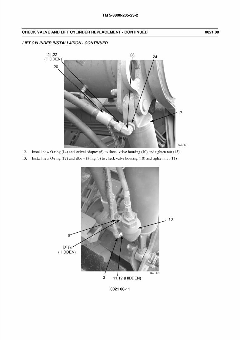
8/14/2019 TM 5-3800-205-23-2 MODEL 613CS
http://slidepdf.com/reader/full/tm-5-3800-205-23-2-model-613cs 121/276
TM 5-3800-205-23-2
0021 00-11
CHECK VALVE AND LIFT CYLINDER REPLACEMENT - CONTINUED 0021 00
LIFT CYLINDER INSTALLATION - CONTINUED
12. Install new O-ring (14) and swivel adapter (6) to check valve housing (10) and tighten nut (13).
13. Install new O-ring (12) and elbow fitting (3) to check valve housing (10) and tighten nut (11).
20
21,22 2324
17
(HIDDEN)
390-1211
10
11,12 (HIDDEN)3
13,14
6
(HIDDEN)
390-1212
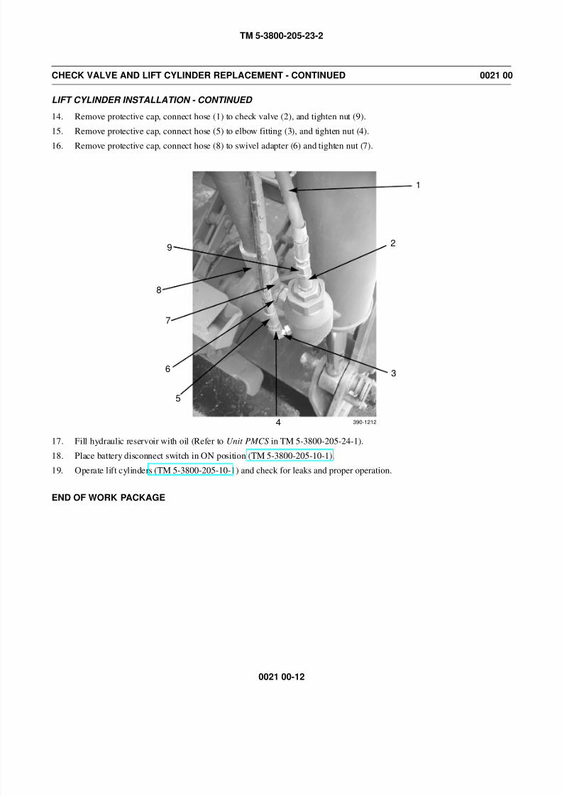
8/14/2019 TM 5-3800-205-23-2 MODEL 613CS
http://slidepdf.com/reader/full/tm-5-3800-205-23-2-model-613cs 122/276
TM 5-3800-205-23-2
0021 00-12
CHECK VALVE AND LIFT CYLINDER REPLACEMENT - CONTINUED 0021 00
LIFT CYLINDER INSTALLATION - CONTINUED
14. Remove protective cap, connect hose (1) to check valve (2), and tighten nut (9).
15. Remove protective cap, connect hose (5) to elbow fitting (3), and tighten nut (4).
16. Remove protective cap, connect hose (8) to swivel adapter (6) and tighten nut (7).
17. Fill hydraulic reservoir with oil (Refer to Unit PMCS in TM 5-3800-205-24-1).
18. Place battery disconnect switch in ON position (TM 5-3800-205-10-1).
19. Operate lift cylinders (TM 5-3800-205-10-1) and check for leaks and proper operation.
END OF WORK PACKAGE
2
3
4
5
6
7
8
9
390-1212
1

8/14/2019 TM 5-3800-205-23-2 MODEL 613CS
http://slidepdf.com/reader/full/tm-5-3800-205-23-2-model-613cs 123/276
TM 5-3800-205-23-2
0022 00-1
ELEVATOR ASSEMBLY ADJUSTMENT 0022 00
THIS WORK PACKAGE COVERS
Adjustment
INITIAL SETUP
Maintenance Level
Unit
Tools and Special Tools
Tool kit, general mechanic’s (Item 33, WP 0048 00)
Equipment Condition
Machine parked on hard, level surface (TM 5-3800-
205-10-1)
Equipment Condition - Continued
Scraper bowl lowered to ground (TM 5-3800-205-
10-1)
Parking brake applied (TM 5-3800-205-10-1)
Wheels chocked (TM 5-3800-205-10-1)
Battery disconnect switch in OFF position (TM 5-
3800-205-10-1)
ADJUSTMENT
NOTE
• Clearance between elevator flights and top of cutting edge may be adjusted. Distance between
top of cutting edge and elevator flight is set at factory at approximately 2.4 in. (61 mm). Two
shims are located at top of bracket when machine is shipped from factory. Brackets are located
on each side of the bowl. Shims must be equally placed on each of the brackets.
• Shims may need to be added to top of bracket when working on material which is compacted.Space that is between cutting edge and elevator flight will become wider. Shims may also need
to be added to top of bracket when components of elevator become worn.
• Shims may need to be moved from top of bracket when working on loose material. Space
between cutting edge and elevator flight will become narrower.
1. Raise front of elevator (1) with jack or hoist and place
blocks or stands under front of elevator. Lower eleva-
tor until resting on blocks or stands.
1
390-1150
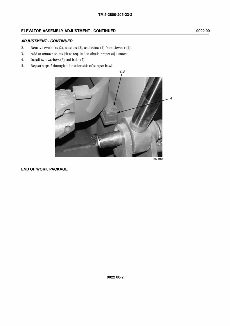
8/14/2019 TM 5-3800-205-23-2 MODEL 613CS
http://slidepdf.com/reader/full/tm-5-3800-205-23-2-model-613cs 124/276
TM 5-3800-205-23-2
0022 00-2
ELEVATOR ASSEMBLY ADJUSTMENT - CONTINUED 0022 00
ADJUSTMENT - CONTINUED
2. Remove two bolts (2), washers (3), and shims (4) from elevator (1).
3. Add or remove shims (4) as required to obtain proper adjustment.
4. Install two washers (3) and bolts (2).
5. Repeat steps 2 through 4 for other side of scraper bowl.
END OF WORK PACKAGE
390-1152
2,3
4

8/14/2019 TM 5-3800-205-23-2 MODEL 613CS
http://slidepdf.com/reader/full/tm-5-3800-205-23-2-model-613cs 125/276
TM 5-3800-205-23-2
0023 00-1
ELEVATOR FLIGHTS AND CHAINS REPLACEMENT 0023 00
THIS WORK PACKAGE COVERS
Removal, Installation
INITIAL SETUP
Maintenance Level
Unit
Tools and Special Tools
Tool kit, general mechanic’s (Item 33, WP 0048 00)
Shop equipment, common no. 1 (Item 24, WP 0048
00)
Sling, nylon (2) (Item 27, WP 0048 00)
Wrench clamp, chain cutter (Item 36, WP 0048 00)
Personnel Required
Two
References
WP 0025 00
Equipment Condition
Elevator guard removed (WP 0024 00)
REMOVAL
NOTE
Master link is an offset link. There is one master link on each chain.
1. Rotate chain (1) and flights (2) until master link (3) is in front of scraper bowl. Position wood blocks under chain and
flights.
2. Attach a nylon strap and suitable lifting device to flights (2) and chain (1).
3. Remove bolt (4) from bracket (5) and lower elevator chain adjustment roller (7) against elevator (6). Repeat step for
other side. Remove lifting device and nylon strap from flights (2) and chain (1).
1 3
WOOD
4 5
67
390-776 390-777
BLOCKS
2
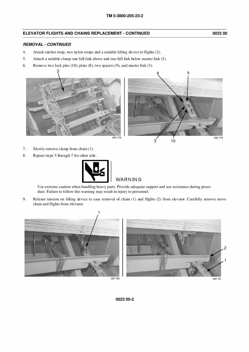
8/14/2019 TM 5-3800-205-23-2 MODEL 613CS
http://slidepdf.com/reader/full/tm-5-3800-205-23-2-model-613cs 126/276
TM 5-3800-205-23-2
0023 00-2
ELEVATOR FLIGHTS AND CHAINS REPLACEMENT - CONTINUED 0023 00
REMOVAL - CONTINUED
4. Attach ratchet strap, two nylon straps and a suitable lifting device to flights (2).
5. Attach a suitable clamp one full link above and one full link below master link (3).
6. Remove two lock pins (10), plate (8), two spacers (9), and master link (3).
7. Slowly remove clamp from chain (1).
8. Repeat steps 5 through 7 for other side.
WARNING
Use extreme caution when handling heavy parts. Provide adequate support and use assistance during proce-
dure. Failure to follow this warning may result in injury to personnel.
9. Release tension on lifting device to ease removal of chain (1) and flights (2) from elevator. Carefully remove move
chain and flights from elevator.
2
10
98
3390-778 390-779
1
1
2
390-780 390-781
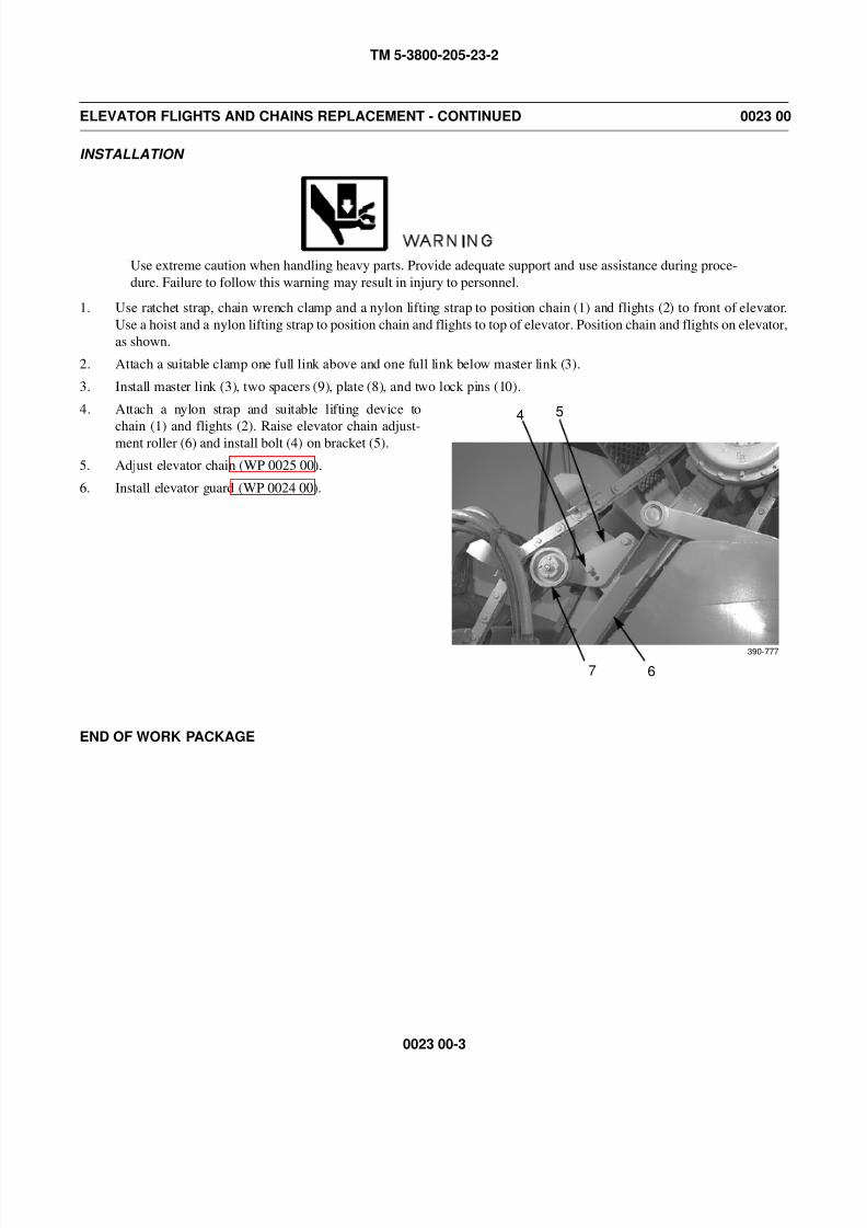
8/14/2019 TM 5-3800-205-23-2 MODEL 613CS
http://slidepdf.com/reader/full/tm-5-3800-205-23-2-model-613cs 127/276
TM 5-3800-205-23-2
0023 00-3
ELEVATOR FLIGHTS AND CHAINS REPLACEMENT - CONTINUED 0023 00
INSTALLATION
WARNING
Use extreme caution when handling heavy parts. Provide adequate support and use assistance during proce-
dure. Failure to follow this warning may result in injury to personnel.
1. Use ratchet strap, chain wrench clamp and a nylon lifting strap to position chain (1) and flights (2) to front of elevator.
Use a hoist and a nylon lifting strap to position chain and flights to top of elevator. Position chain and flights on elevator,
as shown.
2. Attach a suitable clamp one full link above and one full link below master link (3).
3. Install master link (3), two spacers (9), plate (8), and two lock pins (10).
4. Attach a nylon strap and suitable lifting device to
chain (1) and flights (2). Raise elevator chain adjust-ment roller (6) and install bolt (4) on bracket (5).
5. Adjust elevator chain (WP 0025 00).
6. Install elevator guard (WP 0024 00).
END OF WORK PACKAGE
4 5
67
390-777

8/14/2019 TM 5-3800-205-23-2 MODEL 613CS
http://slidepdf.com/reader/full/tm-5-3800-205-23-2-model-613cs 128/276
TM 5-3800-205-23-2
0023 00-4
This Page Intentionally Left Blank.
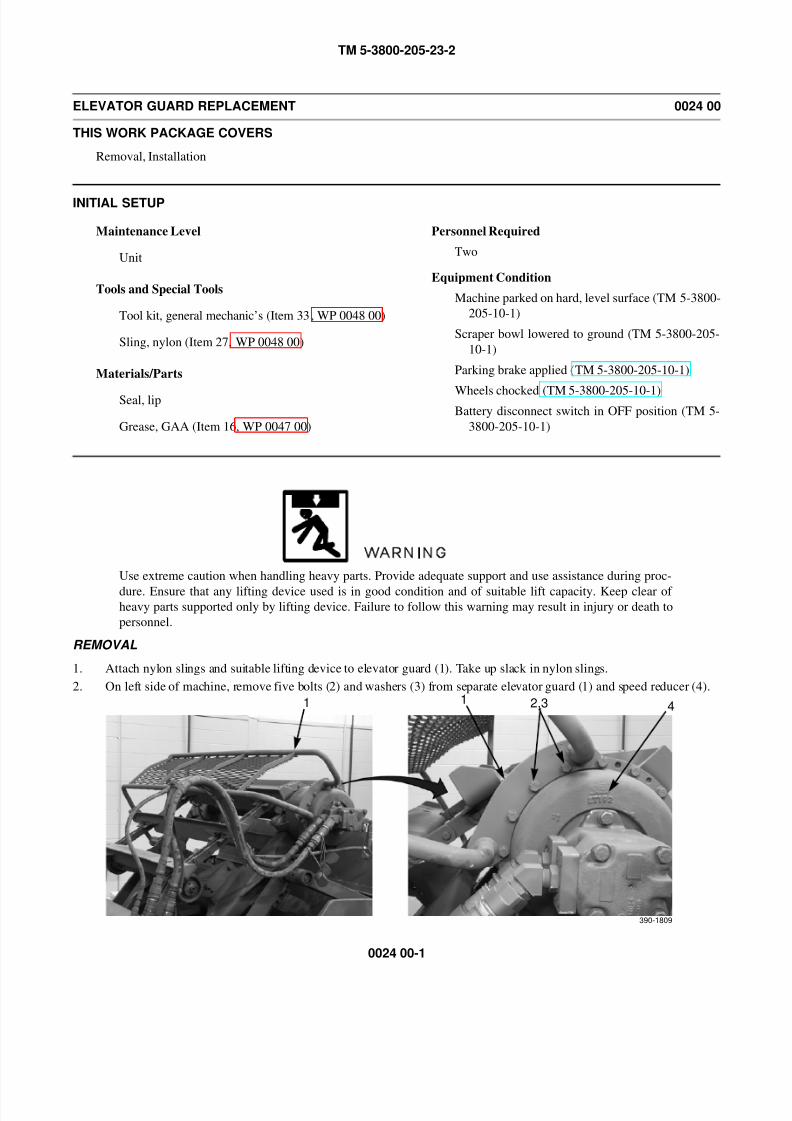
8/14/2019 TM 5-3800-205-23-2 MODEL 613CS
http://slidepdf.com/reader/full/tm-5-3800-205-23-2-model-613cs 129/276
TM 5-3800-205-23-2
0024 00-1
ELEVATOR GUARD REPLACEMENT 0024 00
THIS WORK PACKAGE COVERS
Removal, Installation
INITIAL SETUP
Maintenance Level
Unit
Tools and Special Tools
Tool kit, general mechanic’s (Item 33, WP 0048 00)
Sling, nylon (Item 27, WP 0048 00)
Materials/Parts
Seal, lip
Grease, GAA (Item 16, WP 0047 00)
Personnel Required
Two
Equipment Condition
Machine parked on hard, level surface (TM 5-3800-
205-10-1)
Scraper bowl lowered to ground (TM 5-3800-205-
10-1)
Parking brake applied (TM 5-3800-205-10-1)
Wheels chocked (TM 5-3800-205-10-1)Battery disconnect switch in OFF position (TM 5-
3800-205-10-1)
WARNING
Use extreme caution when handling heavy parts. Provide adequate support and use assistance during proc-
dure. Ensure that any lifting device used is in good condition and of suitable lift capacity. Keep clear of heavy parts supported only by lifting device. Failure to follow this warning may result in injury or death to
personnel.
REMOVAL
1. Attach nylon slings and suitable lifting device to elevator guard (1). Take up slack in nylon slings.
2. On left side of machine, remove five bolts (2) and washers (3) from separate elevator guard (1) and speed reducer (4).
1 1 2,3 4
390-1809

8/14/2019 TM 5-3800-205-23-2 MODEL 613CS
http://slidepdf.com/reader/full/tm-5-3800-205-23-2-model-613cs 130/276
TM 5-3800-205-23-2
0024 00-2
ELEVATOR GUARD REPLACEMENT - CONTINUED 0024 00
REMOVAL - CONTINUED
3. On right side of machine, remove three nuts (5), wash-
ers (6), bolts (7), and elevator guard (1) from elevator
frame (8).
INSTALLATION
1. Attach nylon slings and a suitable lifting device to elevator guard (1). Position elevator guard on machine.
2. On right side of machine, install elevator guard (1) on elevator frame (8) with three bolts (7), washers (6), and nuts (5).
3. At left side of machine, install elevator guard (1) to speed reducer (4) with five washers (3) and bolts (2).
4. Remove nylon slings from elevator guard (1).
END OF WORK PACKAGE
1
7
8
56
7
390-1779
1 1 2,3 4
390-1809
8/14/2019 TM 5-3800-205-23-2 MODEL 613CS
http://slidepdf.com/reader/full/tm-5-3800-205-23-2-model-613cs 131/276
TM 5-3800-205-23-2
0025 00-1
ELEVATOR CHAIN ADJUSTMENT 0025 00
THIS WORK PACKAGE COVERS
Adjustment
INITIAL SETUP
Maintenance Level
Unit
Tools and Special Tools
Tool kit, general mechanic’s (Item 33, WP 0048 00)
Personnel Required
Two
Equipment Condition
Machine parked on hard, level surface (TM 5-3800-
205-10-1)
Scraper bowl lowered to ground (TM 5-3800-205-
10-1)
Parking brake applied (TM 5-3800-205-10-1)
Wheels chocked (TM 5-3800-205-10-1)
Battery disconnect switch in OFF position (TM 5-
3800-205-10-1)
ADJUSTMENT
NOTE
• Elevator chain requires adjustment when distance between bottom of elevator frame and eleva-
tor chain is greater than 9 in. (229 mm). Distance between bottom of elevator frame and eleva-
tor chain should be 5-9 in. (127-229 mm).
• When an adjustment is made to one elevator chain, the same adjustment must be made to sec-
ond elevator chain.
1. Measure elevator chain slack. Take measurement approximately half way between upper sprocket and lower idler, at
widest space between edge of elevator frame and upper side of chain. Chain slack must be 5-9 in. (127-229 mm).
NOTE
• Arm can be moved to another position to tighten elevator chain.
• One link changes the length of the chain approximately 4 in. (100 mm).
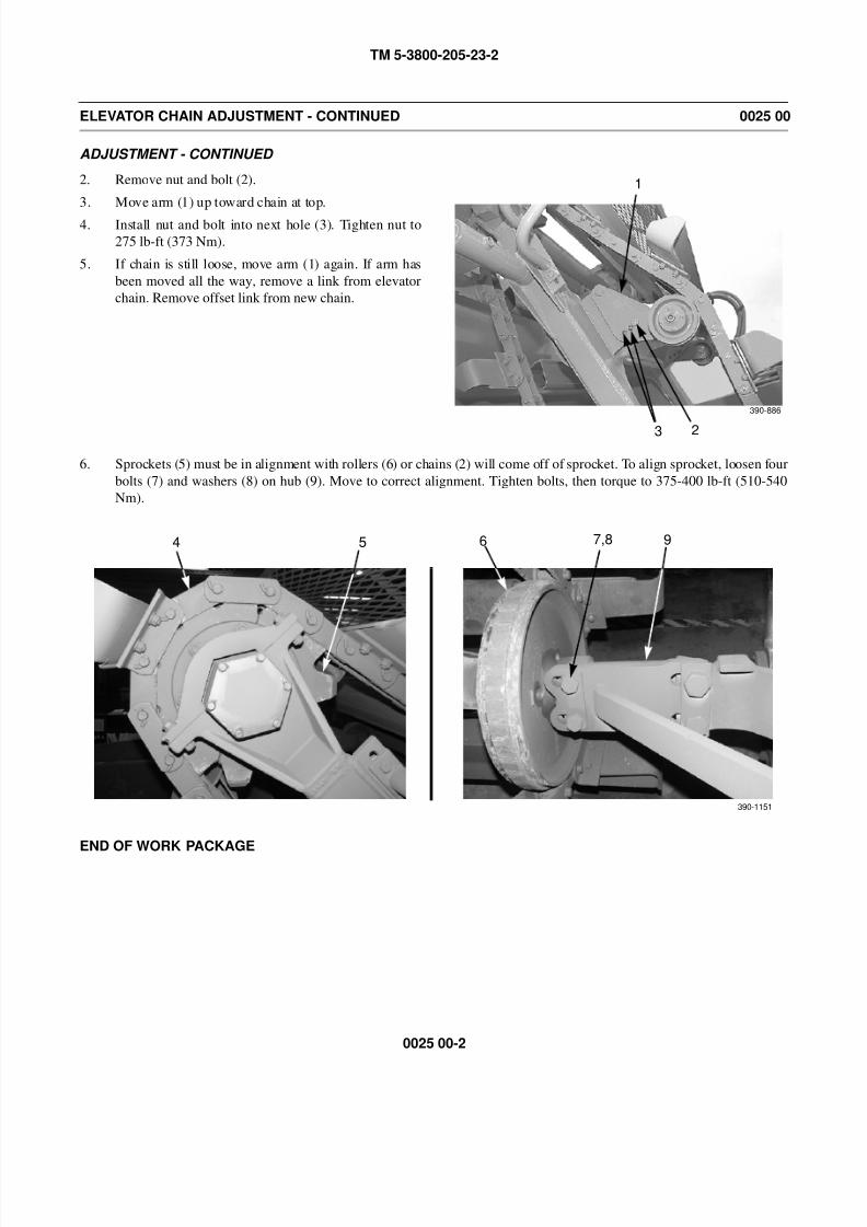
8/14/2019 TM 5-3800-205-23-2 MODEL 613CS
http://slidepdf.com/reader/full/tm-5-3800-205-23-2-model-613cs 132/276
TM 5-3800-205-23-2
0025 00-2
ELEVATOR CHAIN ADJUSTMENT - CONTINUED 0025 00
ADJUSTMENT - CONTINUED
2. Remove nut and bolt (2).
3. Move arm (1) up toward chain at top.
4. Install nut and bolt into next hole (3). Tighten nut to
275 lb-ft (373 Nm).
5. If chain is still loose, move arm (1) again. If arm has
been moved all the way, remove a link from elevator
chain. Remove offset link from new chain.
6. Sprockets (5) must be in alignment with rollers (6) or chains (2) will come off of sprocket. To align sprocket, loosen four
bolts (7) and washers (8) on hub (9). Move to correct alignment. Tighten bolts, then torque to 375-400 lb-ft (510-540
Nm).
END OF WORK PACKAGE
1
23
390-886
390-1151
5 7,8 964
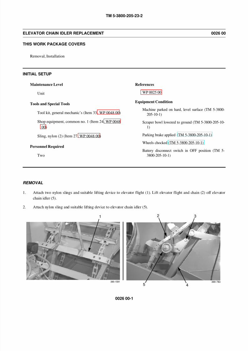
8/14/2019 TM 5-3800-205-23-2 MODEL 613CS
http://slidepdf.com/reader/full/tm-5-3800-205-23-2-model-613cs 133/276
TM 5-3800-205-23-2
0026 00-1
ELEVATOR CHAIN IDLER REPLACEMENT 0026 00
THIS WORK PACKAGE COVERS
Removal, Installation
INITIAL SETUP
Maintenance Level
Unit
Tools and Special Tools
Tool kit, general mechanic’s (Item 33, WP 0048 00)
Shop equipment, common no. 1 (Item 24, WP 004800)
Sling, nylon (2) (Item 27, WP 0048 00)
Personnel Required
Two
References
WP 0025 00
Equipment Condition
Machine parked on hard, level surface (TM 5-3800-
205-10-1)
Scraper bowl lowered to ground (TM 5-3800-205-10-1)
Parking brake applied (TM 5-3800-205-10-1)
Wheels chocked (TM 5-3800-205-10-1)
Battery disconnect switch in OFF position (TM 5-
3800-205-10-1)
REMOVAL
1. Attach two nylon slings and suitable lifting device to elevator flight (1). Lift elevator flight and chain (2) off elevator
chain idler (5).
2. Attach nylon sling and suitable lifting device to elevator chain idler (5).
1
390-1591
2 3
45390-783
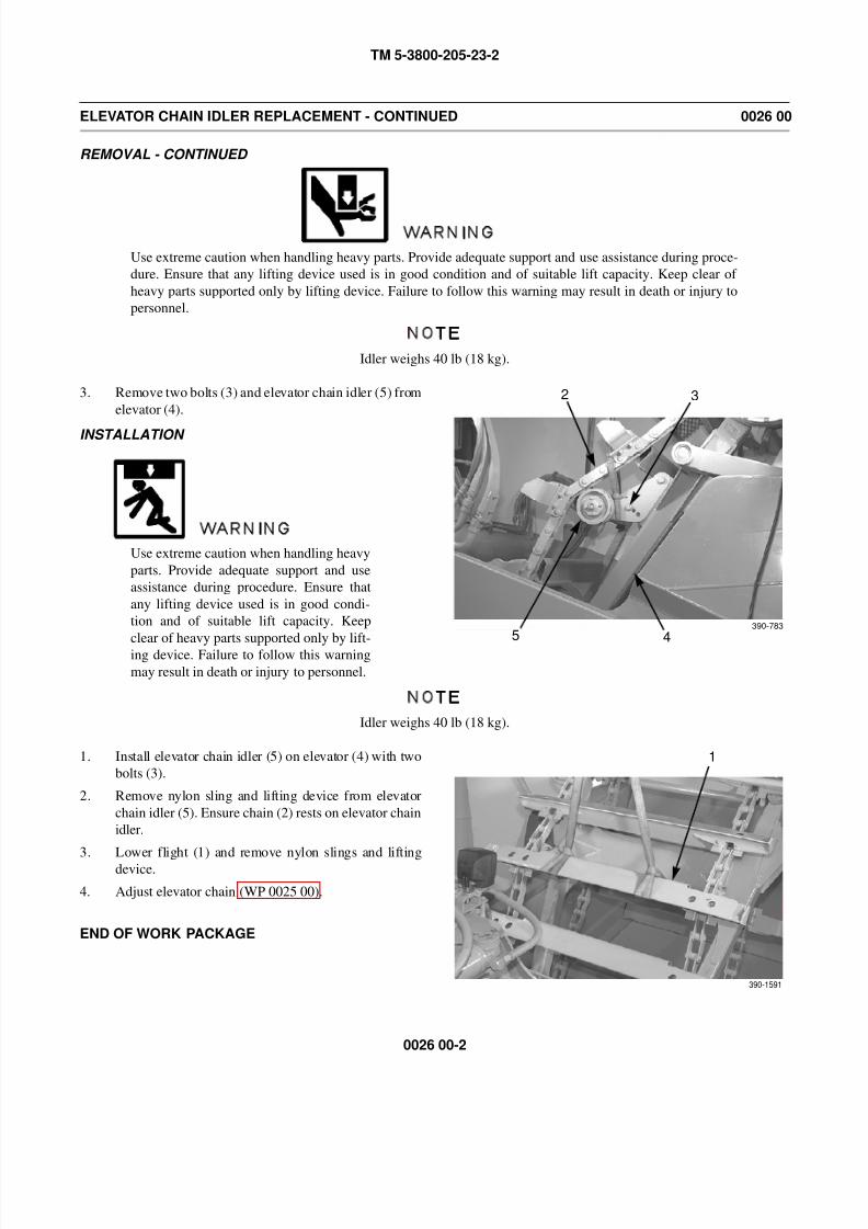
8/14/2019 TM 5-3800-205-23-2 MODEL 613CS
http://slidepdf.com/reader/full/tm-5-3800-205-23-2-model-613cs 134/276
TM 5-3800-205-23-2
0026 00-2
ELEVATOR CHAIN IDLER REPLACEMENT - CONTINUED 0026 00
REMOVAL - CONTINUED
WARNING
Use extreme caution when handling heavy parts. Provide adequate support and use assistance during proce-
dure. Ensure that any lifting device used is in good condition and of suitable lift capacity. Keep clear of
heavy parts supported only by lifting device. Failure to follow this warning may result in death or injury to
personnel.
NOTE
Idler weighs 40 lb (18 kg).
3. Remove two bolts (3) and elevator chain idler (5) from
elevator (4).
INSTALLATION
WARNING
Use extreme caution when handling heavy
parts. Provide adequate support and use
assistance during procedure. Ensure that
any lifting device used is in good condi-
tion and of suitable lift capacity. Keep
clear of heavy parts supported only by lift-
ing device. Failure to follow this warning
may result in death or injury to personnel.
NOTE
Idler weighs 40 lb (18 kg).
1. Install elevator chain idler (5) on elevator (4) with two
bolts (3).
2. Remove nylon sling and lifting device from elevator
chain idler (5). Ensure chain (2) rests on elevator chain
idler.
3. Lower flight (1) and remove nylon slings and lifting
device.
4. Adjust elevator chain (WP 0025 00).
END OF WORK PACKAGE
2 3
45390-783
1
390-1591

8/14/2019 TM 5-3800-205-23-2 MODEL 613CS
http://slidepdf.com/reader/full/tm-5-3800-205-23-2-model-613cs 135/276
TM 5-3800-205-23-2
CHAPTER 2
DIRECT SUPPORT LEVEL
SCRAPER MAINTENANCE

8/14/2019 TM 5-3800-205-23-2 MODEL 613CS
http://slidepdf.com/reader/full/tm-5-3800-205-23-2-model-613cs 136/276
TM 5-3800-205-23-2
This Page Intentionally Left Blank.
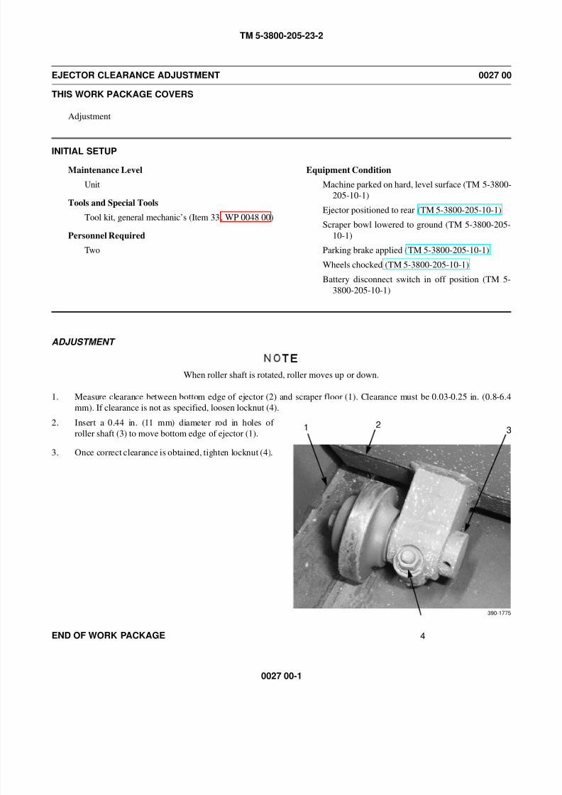
8/14/2019 TM 5-3800-205-23-2 MODEL 613CS
http://slidepdf.com/reader/full/tm-5-3800-205-23-2-model-613cs 137/276
TM 5-3800-205-23-2
0027 00-1
EJECTOR CLEARANCE ADJUSTMENT 0027 00
THIS WORK PACKAGE COVERS
Adjustment
INITIAL SETUP
Maintenance Level
Unit
Tools and Special Tools
Tool kit, general mechanic’s (Item 33, WP 0048 00)
Personnel Required
Two
Equipment Condition
Machine parked on hard, level surface (TM 5-3800-
205-10-1)
Ejector positioned to rear (TM 5-3800-205-10-1)
Scraper bowl lowered to ground (TM 5-3800-205-
10-1)
Parking brake applied (TM 5-3800-205-10-1)
Wheels chocked (TM 5-3800-205-10-1)
Battery disconnect switch in off position (TM 5-3800-205-10-1)
ADJUSTMENT
NOTE
When roller shaft is rotated, roller moves up or down.
1. Measure clearance between bottom edge of ejector (2) and scraper floor (1). Clearance must be 0.03-0.25 in. (0.8-6.4
mm). If clearance is not as specified, loosen locknut (4).
2. Insert a 0.44 in. (11 mm) diameter rod in holes of
roller shaft (3) to move bottom edge of ejector (1).
3. Once correct clearance is obtained, tighten locknut (4).
END OF WORK PACKAGE
1 23
390-1775
4

8/14/2019 TM 5-3800-205-23-2 MODEL 613CS
http://slidepdf.com/reader/full/tm-5-3800-205-23-2-model-613cs 138/276
TM 5-3800-205-23-2
0027 00-2
This Page Intentionally Left Blank.
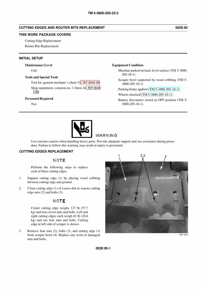
8/14/2019 TM 5-3800-205-23-2 MODEL 613CS
http://slidepdf.com/reader/full/tm-5-3800-205-23-2-model-613cs 139/276
TM 5-3800-205-23-2
0028 00-1
CUTTING EDGES AND ROUTER BITS REPLACEMENT 0028 00
THIS WORK PACKAGE COVERS
Cutting Edge Replacement
Router Bits Replacement
INITIAL SETUP
Maintenance Level
Unit
Tools and Special Tools
Tool kit, general mechanic’s (Item 33, WP 0048 00)
Shop equipment, common no. 1 (Item 24, WP 0048
00)
Personnel Required
Two
Equipment Condition
Machine parked on hard, level surface (TM 5-3800-
205-10-1)
Scraper bowl supported by wood cribbing (TM 5-
3800-205-10-1)
Parking brake applied (TM 5-3800-205-10-1)
Wheels chocked (TM 5-3800-205-10-1)
Battery disconnect switch in OFF position (TM 5-
3800-205-10-1)
WARNING
Use extreme caution when handling heavy parts. Provide adequate support and use assistance during proce-
dure. Failure to follow this warning may result in injury to personnel.
CUTTING EDGES REPLACEMENT
NOTE
Perform the following steps to replace
each of three cutting edges.
1. Support cutting edge (1) by placing wood cribbing
between cutting edge and ground.
2. Clean cutting edge (1) of excess dirt to expose cutting
edge nuts (2) and bolts (3).
NOTE
Center cutting edge weighs 127 lb (57.7
kg) and uses seven nuts and bolts. Left and
right cutting edges each weigh 63 lb (28.6
kg) and use four nuts and bolts. Cutting
edge at left side of scraper is shown.
3. Remove four nuts (2), bolts (3), and cutting edge (1)
from scraper bowl (4). Replace any worn or damaged
nuts and bolts.
1 2,3 4
390-1810
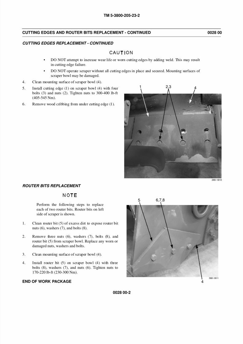
8/14/2019 TM 5-3800-205-23-2 MODEL 613CS
http://slidepdf.com/reader/full/tm-5-3800-205-23-2-model-613cs 140/276
TM 5-3800-205-23-2
0028 00-2
CUTTING EDGES AND ROUTER BITS REPLACEMENT - CONTINUED 0028 00
CUTTING EDGES REPLACEMENT - CONTINUED
CAUTION
• DO NOT attempt to increase wear life or worn cutting edges by adding weld. This may resultin cutting edge failure.
• DO NOT operate scraper without all cutting edges in place and secured. Mounting surfaces of
scraper bowl may be damaged.
4. Clean mounting surface of scraper bowl (4).
5. Install cutting edge (1) on scraper bowl (4) with four
bolts (3) and nuts (2). Tighten nuts to 300-400 lb-ft
(405-545 Nm).
6. Remove wood cribbing from under cutting edge (1).
ROUTER BITS REPLACEMENT
NOTE
Perform the following steps to replace
each of two router bits. Router bits on left
side of scraper is shown.
1. Clean router bit (5) of excess dirt to expose router bit
nuts (6), washers (7), and bolts (8).
2. Remove three nuts (6), washers (7), bolts (8), and
router bit (5) from scraper bowl. Replace any worn ordamaged nuts, washers and bolts.
3. Clean mounting surface of scraper bowl (4).
4. Install router bit (5) on scraper bowl (4) with three
bolts (8), washers (7), and nuts (6). Tighten nuts to
170-220 lb-ft (230-300 Nm).
END OF WORK PACKAGE
1 2,3 4
390-1810
5 6,7,8
4390-1811
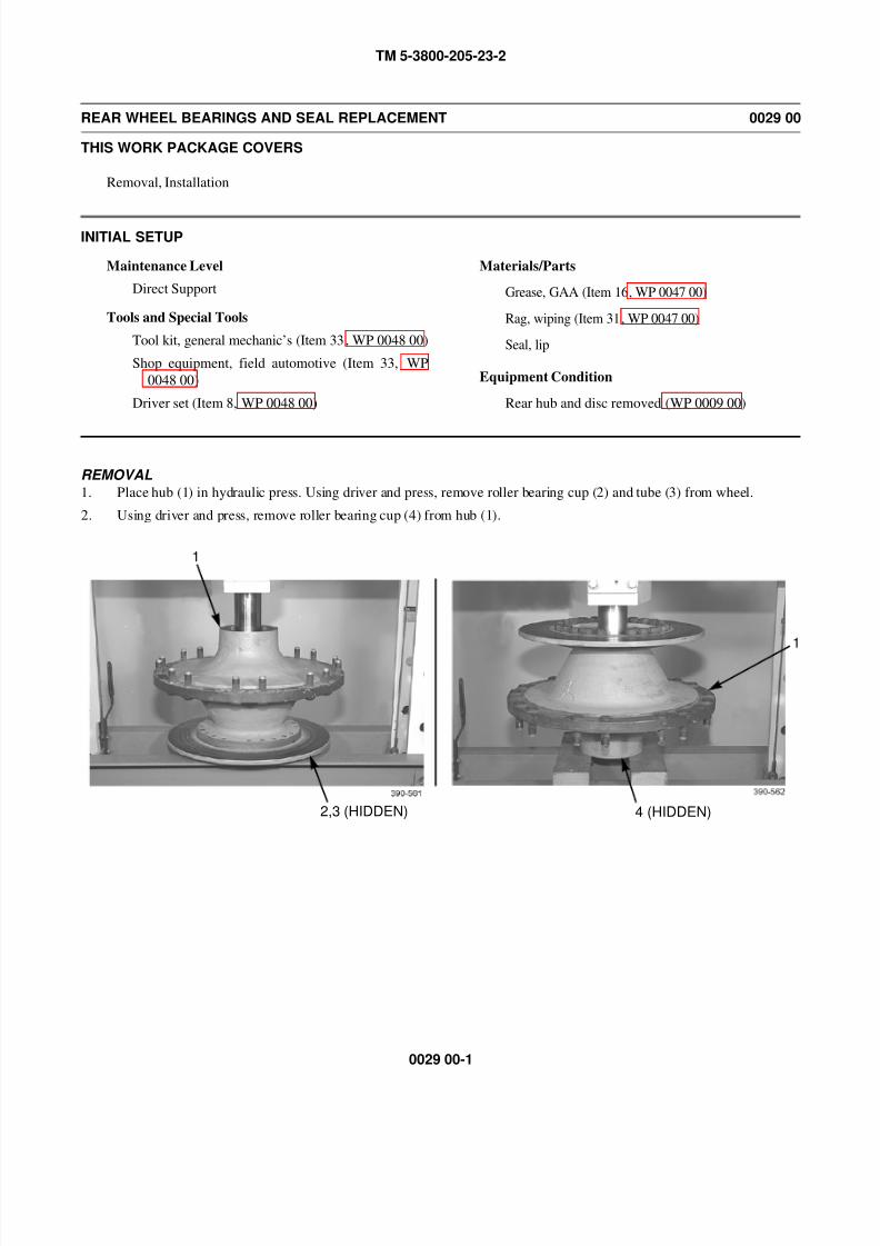
8/14/2019 TM 5-3800-205-23-2 MODEL 613CS
http://slidepdf.com/reader/full/tm-5-3800-205-23-2-model-613cs 141/276
TM 5-3800-205-23-2
0029 00-1
REAR WHEEL BEARINGS AND SEAL REPLACEMENT 0029 00
THIS WORK PACKAGE COVERS
Removal, Installation
INITIAL SETUP
Maintenance Level
Direct Support
Tools and Special Tools
Tool kit, general mechanic’s (Item 33, WP 0048 00)
Shop equipment, field automotive (Item 33, WP
0048 00)
Driver set (Item 8, WP 0048 00)
Materials/Parts
Grease, GAA (Item 16, WP 0047 00)
Rag, wiping (Item 31, WP 0047 00)
Seal, lip
Equipment Condition
Rear hub and disc removed (WP 0009 00)
REMOVAL1. Place hub (1) in hydraulic press. Using driver and press, remove roller bearing cup (2) and tube (3) from wheel.
2. Using driver and press, remove roller bearing cup (4) from hub (1).
1
2,3 (HIDDEN)
1
4 (HIDDEN)
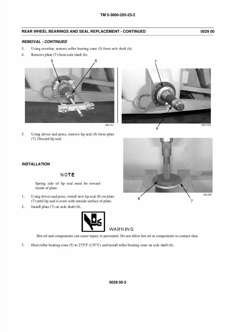
8/14/2019 TM 5-3800-205-23-2 MODEL 613CS
http://slidepdf.com/reader/full/tm-5-3800-205-23-2-model-613cs 142/276
TM 5-3800-205-23-2
0029 00-2
REAR WHEEL BEARINGS AND SEAL REPLACEMENT - CONTINUED 0029 00
REMOVAL - CONTINUED
3. Using crossbar, remove roller bearing cone (5) from axle shaft (6).
4. Remove plate (7) from axle shaft (6).
5. Using driver and press, remove lip seal (8) from plate
(7). Discard lip seal.
INSTALLATION
NOTE
Spring side of lip seal must be toward
inside of plate.
1. Using driver and press, install new lip seal (8) on plate
(7) until lip seal is even with outside surface of plate.
2. Install plate (7) on axle shaft (6).
WARNING
Hot oil and components can cause injury to personnel. Do not allow hot oil or components to contact skin.
3. Heat roller bearing cone (5) to 275°F (135°C) and install roller bearing cone on axle shaft (6).
5 6 7
6
87
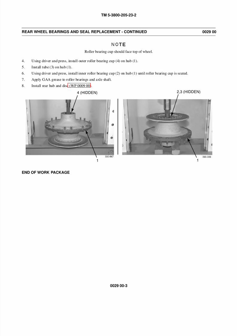
8/14/2019 TM 5-3800-205-23-2 MODEL 613CS
http://slidepdf.com/reader/full/tm-5-3800-205-23-2-model-613cs 143/276
TM 5-3800-205-23-2
0029 00-3
REAR WHEEL BEARINGS AND SEAL REPLACEMENT - CONTINUED 0029 00
NOTE
Roller bearing cup should face top of wheel.
4. Using driver and press, install outer roller bearing cup (4) on hub (1).
5. Install tube (3) on hub (1).
6. Using driver and press, install inner roller bearing cup (2) on hub (1) until roller bearing cup is seated.
7. Apply GAA grease to roller bearings and axle shaft.
8. Install rear hub and disc (WP 0009 00).
END OF WORK PACKAGE
4 (HIDDEN)
1
2,3 (HIDDEN)
1

8/14/2019 TM 5-3800-205-23-2 MODEL 613CS
http://slidepdf.com/reader/full/tm-5-3800-205-23-2-model-613cs 144/276
TM 5-3800-205-23-2
0029 00-4
This Page Intentionally Left Blank.
8/14/2019 TM 5-3800-205-23-2 MODEL 613CS
http://slidepdf.com/reader/full/tm-5-3800-205-23-2-model-613cs 145/276
TM 5-3800-205-23-2
0030 00-1
FLOOR CHECK VALVE REPLACEMENT 0030 00
THIS WORK PACKAGE COVERS
Removal, Installation
INITIAL SETUP
Maintenance Level
Direct Support
Tools and Special Tools
Tool kit, general mechanic’s (Item 33, WP 0048 00)
Materials/Parts
Cap set, protective (Item 5, WP 0047 00)
Oil, lubricating (Item 24 or 29, WP 0047 00)
Rag, wiping (Item 31, WP 0047 00)
Materials/Parts - Continued
Tag, marker (Item 39, WP 0047 00)
O-ring (as required)
References
TM 5-3800-205-23-1
Equipment Condition
Toolbox and rear deck cover removed (WP 001700)
Quick disconnects at right side of draft arms dis-
connected (TM 5-3800-205-10-1)
WARNING
• Do NOT disconnect or remove any hydraulic system line or fitting unless engine is shut down
and hydraulic system pressure has been relieved. Tighten all connections before applying pres-
sure. Escaping hydraulic fluid under pressure can penetrate the skin, causing serious injury.
• At operating temperature hydraulic is hot. Allow hydraulic oil to cool before disconnecting
any hydraulics. Failure to do so could result in injury.
• Hydraulic oil is very slippery. Immediately wipe up any spills. Failure to follow this warning
may result in injury to personnel.
CAUTION
Cap all hoses to prevent fluid loss and contamination of oil system.
NOTE
• Tag all lines, hoses, wires, and tubes to aid in installation.
• Care must be taken to ensure that fluids are contained during performance of inspection, main-
tenance, testing, adjusting and repair of the machine. Be prepared to collect the fluid with suit-
able containers before opening any compartment or disassembling any component containing
fluids.
• Dispose of all fluids according to local regulations and mandates.
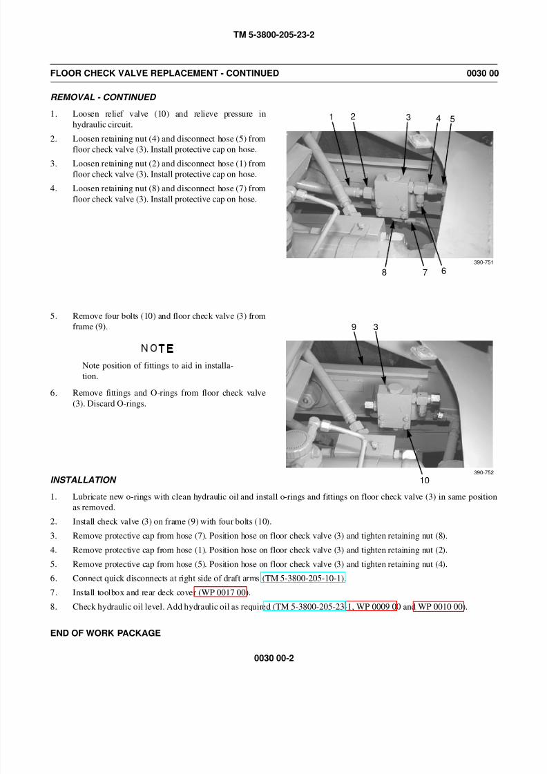
8/14/2019 TM 5-3800-205-23-2 MODEL 613CS
http://slidepdf.com/reader/full/tm-5-3800-205-23-2-model-613cs 146/276
TM 5-3800-205-23-2
0030 00-2
FLOOR CHECK VALVE REPLACEMENT - CONTINUED 0030 00
REMOVAL - CONTINUED
1. Loosen relief valve (10) and relieve pressure in
hydraulic circuit.
2. Loosen retaining nut (4) and disconnect hose (5) from
floor check valve (3). Install protective cap on hose.
3. Loosen retaining nut (2) and disconnect hose (1) from
floor check valve (3). Install protective cap on hose.
4. Loosen retaining nut (8) and disconnect hose (7) from
floor check valve (3). Install protective cap on hose.
5. Remove four bolts (10) and floor check valve (3) from
frame (9).
NOTE
Note position of fittings to aid in installa-
tion.
6. Remove fittings and O-rings from floor check valve
(3). Discard O-rings.
INSTALLATION
1. Lubricate new o-rings with clean hydraulic oil and install o-rings and fittings on floor check valve (3) in same position
as removed.
2. Install check valve (3) on frame (9) with four bolts (10).
3. Remove protective cap from hose (7). Position hose on floor check valve (3) and tighten retaining nut (8).
4. Remove protective cap from hose (1). Position hose on floor check valve (3) and tighten retaining nut (2).
5. Remove protective cap from hose (5). Position hose on floor check valve (3) and tighten retaining nut (4).
6. Connect quick disconnects at right side of draft arms (TM 5-3800-205-10-1).
7. Install toolbox and rear deck cover (WP 0017 00).
8. Check hydraulic oil level. Add hydraulic oil as required (TM 5-3800-205-23-1, WP 0009 00 and WP 0010 00).
END OF WORK PACKAGE
1 2 3 4 5
8 7 6
390-751
3
10
9
390-752

8/14/2019 TM 5-3800-205-23-2 MODEL 613CS
http://slidepdf.com/reader/full/tm-5-3800-205-23-2-model-613cs 147/276
TM 5-3800-205-23-2
0031 00-1
EJECTOR CYLINDER REPLACEMENT 0031 00
THIS WORK PACKAGE COVERS
Removal, Installation
INITIAL SETUP
Maintenance Level
Direct Support
Tools and Special Tools
Tool kit, general mechanic’s (Item 33, WP 0048 00)
Shop equipment, field automotive (Item 23, WP
0048 00)
Materials/Parts
Cap set, protective (Item 5, WP 0047 00)
Grease, GAA (Item 16, WP 0047 00)
Rag, wiping (Item 31, WP 0047 00)
Materials/Parts - Continued
Tag, marker (Item 39, WP 0047 00)
O-ring (as required)
Personnel Required
Two
References
TM 5-3800-205-23-1
Equipment Condition
Toolbox and rear deck cover removed (WP 0017
00)
Quick disconnects at right side of draft arms dis-
connected (TM 5-3800-205-10-1)
WARNING
• Do NOT disconnect or remove any hydraulic system line or fitting unless engine is shut down
and hydraulic system pressure has been relieved. Tighten all connections before applying pres-
sure. Escaping hydraulic fluid under pressure can penetrate the skin, causing serious injury.
• At operating temperature hydraulic is hot. Allow hydraulic oil to cool before disconnecting
any hydraulics. Failure to do so could result in injury.
• Hydraulic oil is very slippery. Immediately wipe up any spills. Failure to follow this warning
may result in injury to personnel.
CAUTION
Cap all hoses and tubes to prevent fluid loss and contamination of oil system.
NOTE
• Tag all lines, hoses, wires, and tubes to aid in installation.
• Care must be taken to ensure that fluids are contained during performance of inspection, main-
tenance, testing, adjusting and repair of the machine. Be prepared to collect the fluid with suit-
able containers before opening any compartment or disassembling any component containing
fluids.
• Dispose of all fluids according to local regulations and mandates.
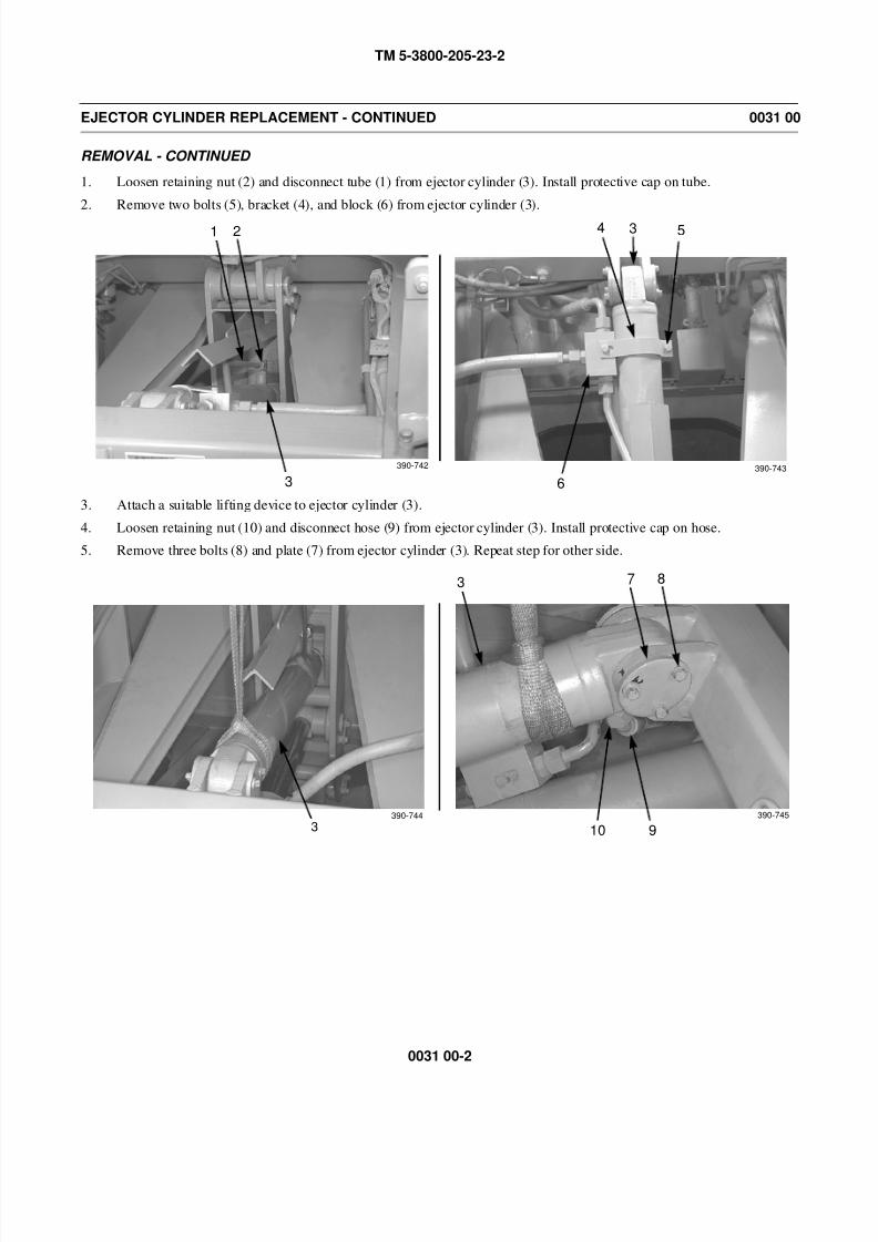
8/14/2019 TM 5-3800-205-23-2 MODEL 613CS
http://slidepdf.com/reader/full/tm-5-3800-205-23-2-model-613cs 148/276
TM 5-3800-205-23-2
0031 00-2
EJECTOR CYLINDER REPLACEMENT - CONTINUED 0031 00
REMOVAL - CONTINUED
1. Loosen retaining nut (2) and disconnect tube (1) from ejector cylinder (3). Install protective cap on tube.
2. Remove two bolts (5), bracket (4), and block (6) from ejector cylinder (3).
3. Attach a suitable lifting device to ejector cylinder (3).
4. Loosen retaining nut (10) and disconnect hose (9) from ejector cylinder (3). Install protective cap on hose.
5. Remove three bolts (8) and plate (7) from ejector cylinder (3). Repeat step for other side.
1 2
3
390-742
4 3 5
6390-743
3390-744
3 7 8
910
390-745
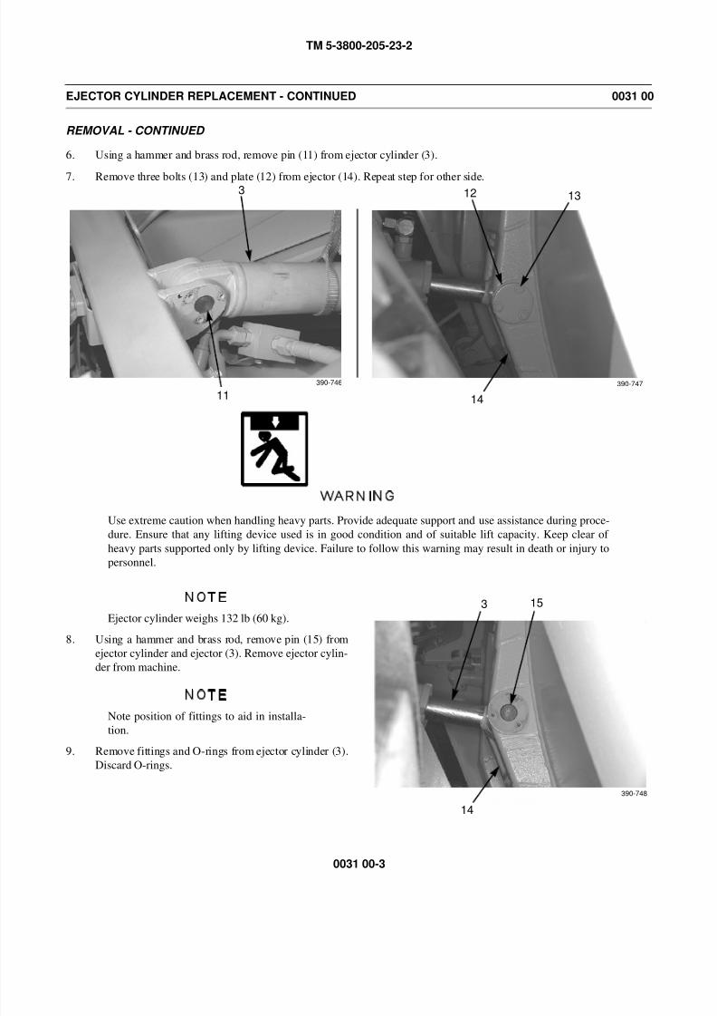
8/14/2019 TM 5-3800-205-23-2 MODEL 613CS
http://slidepdf.com/reader/full/tm-5-3800-205-23-2-model-613cs 149/276
TM 5-3800-205-23-2
0031 00-3
EJECTOR CYLINDER REPLACEMENT - CONTINUED 0031 00
REMOVAL - CONTINUED
6. Using a hammer and brass rod, remove pin (11) from ejector cylinder (3).
7. Remove three bolts (13) and plate (12) from ejector (14). Repeat step for other side.
WARNING
Use extreme caution when handling heavy parts. Provide adequate support and use assistance during proce-
dure. Ensure that any lifting device used is in good condition and of suitable lift capacity. Keep clear of heavy parts supported only by lifting device. Failure to follow this warning may result in death or injury to
personnel.
NOTE
Ejector cylinder weighs 132 lb (60 kg).
8. Using a hammer and brass rod, remove pin (15) from
ejector cylinder and ejector (3). Remove ejector cylin-
der from machine.
NOTE
Note position of fittings to aid in installa-
tion.
9. Remove fittings and O-rings from ejector cylinder (3).
Discard O-rings.
3
11
12 13
14
390-746 390-747
3 15
14
390-748
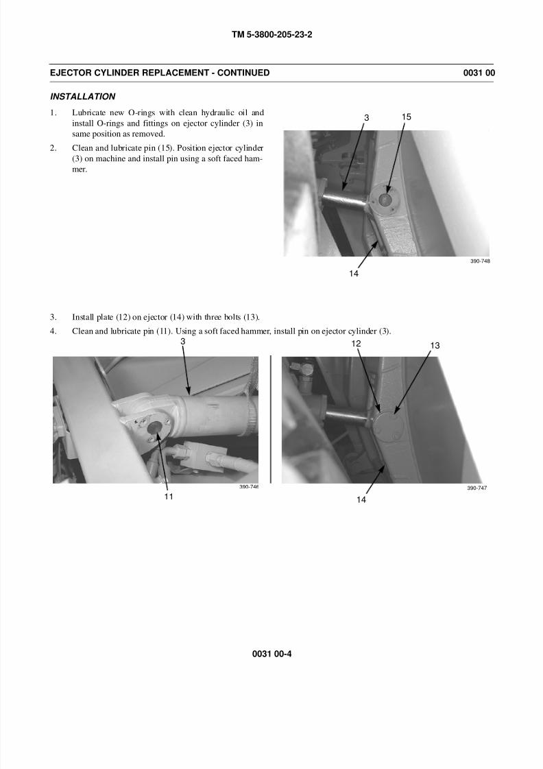
8/14/2019 TM 5-3800-205-23-2 MODEL 613CS
http://slidepdf.com/reader/full/tm-5-3800-205-23-2-model-613cs 150/276
TM 5-3800-205-23-2
0031 00-4
EJECTOR CYLINDER REPLACEMENT - CONTINUED 0031 00
INSTALLATION
1. Lubricate new O-rings with clean hydraulic oil and
install O-rings and fittings on ejector cylinder (3) in
same position as removed.2. Clean and lubricate pin (15). Position ejector cylinder
(3) on machine and install pin using a soft faced ham-
mer.
3. Install plate (12) on ejector (14) with three bolts (13).
4. Clean and lubricate pin (11). Using a soft faced hammer, install pin on ejector cylinder (3).
3 15
14
390-748
3
11
12 13
14
390-746 390-747
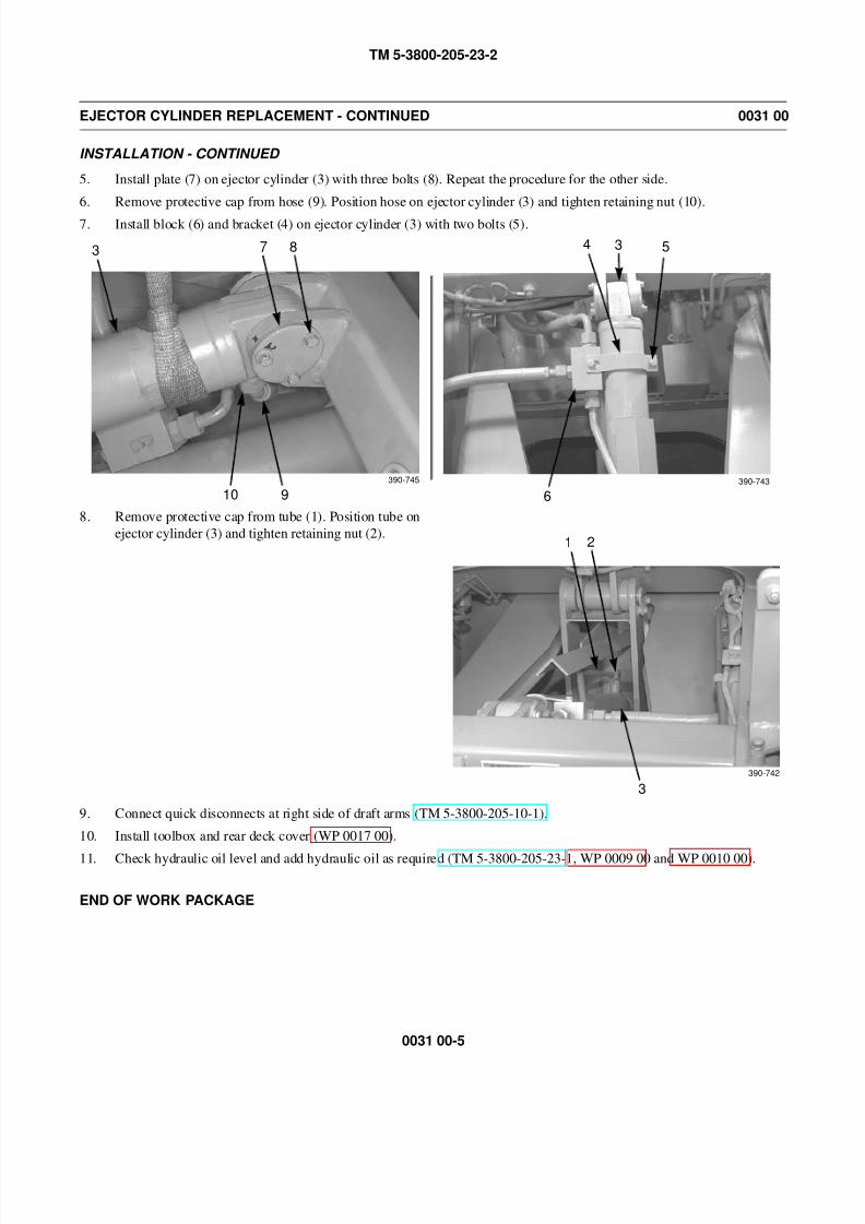
8/14/2019 TM 5-3800-205-23-2 MODEL 613CS
http://slidepdf.com/reader/full/tm-5-3800-205-23-2-model-613cs 151/276
TM 5-3800-205-23-2
0031 00-5
EJECTOR CYLINDER REPLACEMENT - CONTINUED 0031 00
INSTALLATION - CONTINUED
5. Install plate (7) on ejector cylinder (3) with three bolts (8). Repeat the procedure for the other side.
6. Remove protective cap from hose (9). Position hose on ejector cylinder (3) and tighten retaining nut (10).
7. Install block (6) and bracket (4) on ejector cylinder (3) with two bolts (5).
8. Remove protective cap from tube (1). Position tube on
ejector cylinder (3) and tighten retaining nut (2).
9. Connect quick disconnects at right side of draft arms (TM 5-3800-205-10-1).
10. Install toolbox and rear deck cover (WP 0017 00).
11. Check hydraulic oil level and add hydraulic oil as required (TM 5-3800-205-23-1, WP 0009 00 and WP 0010 00).
END OF WORK PACKAGE
3 7 8
910390-745
4 3 5
6390-743
1 2
3
390-742

8/14/2019 TM 5-3800-205-23-2 MODEL 613CS
http://slidepdf.com/reader/full/tm-5-3800-205-23-2-model-613cs 152/276
TM 5-3800-205-23-2
0031 00-6
This Page Intentionally Left Blank.
8/14/2019 TM 5-3800-205-23-2 MODEL 613CS
http://slidepdf.com/reader/full/tm-5-3800-205-23-2-model-613cs 153/276
TM 5-3800-205-23-2
0032 00-1
FLOOR CYLINDER REPLACEMENT 0032 00
THIS WORK PACKAGE COVERS
Removal, Installation
INITIAL SETUP
Maintenance Level
Direct Support
Tools and Special Tools
Tool kit, general mechanic’s (Item 33, WP 0048 00)
Shop equipment, field automotive (Item 23, WP
0048 00)
Personnel Required
Two
Materials/Parts
Cap set, protective (Item 5, WP 0047 00)Oil, hydraulic (Item 24 or 29, WP 0047 00)
Materials/Parts - Continued
Rag, wiping (Item 31, WP 0047 00)
Tag, marker (Item 39, WP 0047 00)
O-rings
References
TM 5-3800-205-23-1
Equipment Condition
Toolbox and rear deck cover removed (WP 0017
00)
Quick disconnects at right side of draft arm discon-nected (TM 5-3800-205-10-1)
WARNING
• Do NOT disconnect or remove any hydraulic system line or fitting unless engine is shut down
and hydraulic system pressure has been relieved. Tighten all connections before applying pres-sure. Escaping hydraulic fluid under pressure can penetrate the skin, causing serious injury.
• At operating temperature hydraulic is hot. Allow hydraulic oil to cool before disconnecting
any hydraulics. Failure to do so could result in injury.
• Hydraulic fluid is very slippery. Immediately wipe up any spills. Failure to follow this warning
may result in injury to personnel.
CAUTION
Cap all hoses and tubes to prevent fluid loss and contamination of oil system.
NOTE
• Tag all lines, hoses, wires, and tubes to aid in installation.
• Care must be taken to ensure that fluids are contained during performance of inspection, main-
tenance, testing, adjusting and repair of the machine. Be prepared to collect the fluid with suit-
able containers before opening any compartment or disassembling any component containing
fluids.
• Dispose of all fluids according to local regulations and mandates.

8/14/2019 TM 5-3800-205-23-2 MODEL 613CS
http://slidepdf.com/reader/full/tm-5-3800-205-23-2-model-613cs 154/276
TM 5-3800-205-23-2
0032 00-2
FLOOR CYLINDER REPLACEMENT - CONTINUED 0032 00
REMOVAL
1. Loosen retaining nut (2) and disconnect tube (3) from floor cylinder (1). Install protective cap on tube.
2. Remove four bolts (4), two half flanges (5), and hose (6) from floor cylinder (1). Install protective cap on hose.
3. Remove two bolts (8), bracket (9) and block (7) from floor cylinder (1).
4. Attach suitable lifting device to floor cylinder (1) and remove three bolts (12) and plate (11) from floor cylinder. Repeat
step for other side.
23
1 1 4 5
6
390-755 390-756
7 8 1
9
1 11 12
390-757 390-758
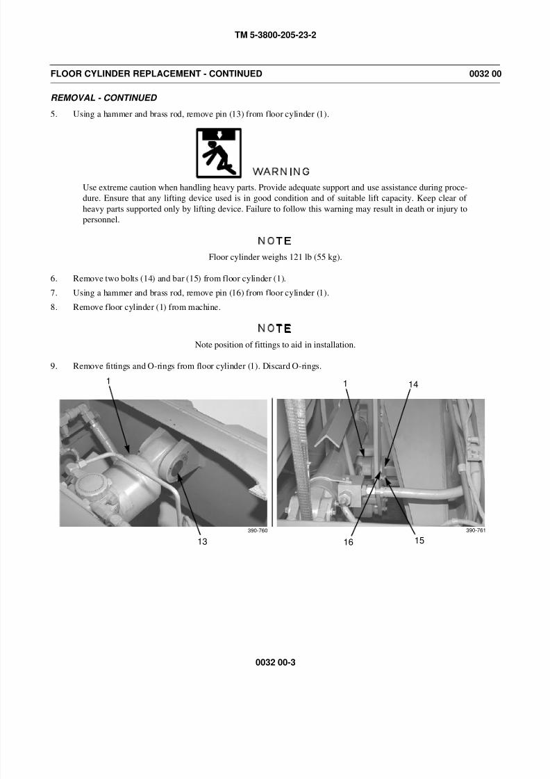
8/14/2019 TM 5-3800-205-23-2 MODEL 613CS
http://slidepdf.com/reader/full/tm-5-3800-205-23-2-model-613cs 155/276
TM 5-3800-205-23-2
0032 00-3
FLOOR CYLINDER REPLACEMENT - CONTINUED 0032 00
REMOVAL - CONTINUED
5. Using a hammer and brass rod, remove pin (13) from floor cylinder (1).
WARNING
Use extreme caution when handling heavy parts. Provide adequate support and use assistance during proce-
dure. Ensure that any lifting device used is in good condition and of suitable lift capacity. Keep clear of
heavy parts supported only by lifting device. Failure to follow this warning may result in death or injury to
personnel.
NOTE
Floor cylinder weighs 121 lb (55 kg).
6. Remove two bolts (14) and bar (15) from floor cylinder (1).
7. Using a hammer and brass rod, remove pin (16) from floor cylinder (1).
8. Remove floor cylinder (1) from machine.
NOTE
Note position of fittings to aid in installation.
9. Remove fittings and O-rings from floor cylinder (1). Discard O-rings.
14
1516
11
13
390-760 390-761
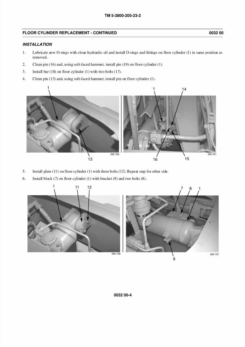
8/14/2019 TM 5-3800-205-23-2 MODEL 613CS
http://slidepdf.com/reader/full/tm-5-3800-205-23-2-model-613cs 156/276
TM 5-3800-205-23-2
0032 00-4
FLOOR CYLINDER REPLACEMENT - CONTINUED 0032 00
INSTALLATION
1. Lubricate new O-rings with clean hydraulic oil and install O-rings and fittings on floor cylinder (1) in same position as
removed.
2. Clean pin (16) and, using soft-faced hammer, install pin (19) on floor cylinder (1).
3. Install bar (18) on floor cylinder (1) with two bolts (17).
4. Clean pin (13) and, using soft-faced hammer, install pin on floor cylinder (1).
5. Install plate (11) on floor cylinder (1) with three bolts (12). Repeat step for other side.
6. Install block (7) on floor cylinder (1) with bracket (9) and two bolts (8).
14
1516
11
13
390-760 390-761
1 11 12
390-758
7 8 1
9
390-757
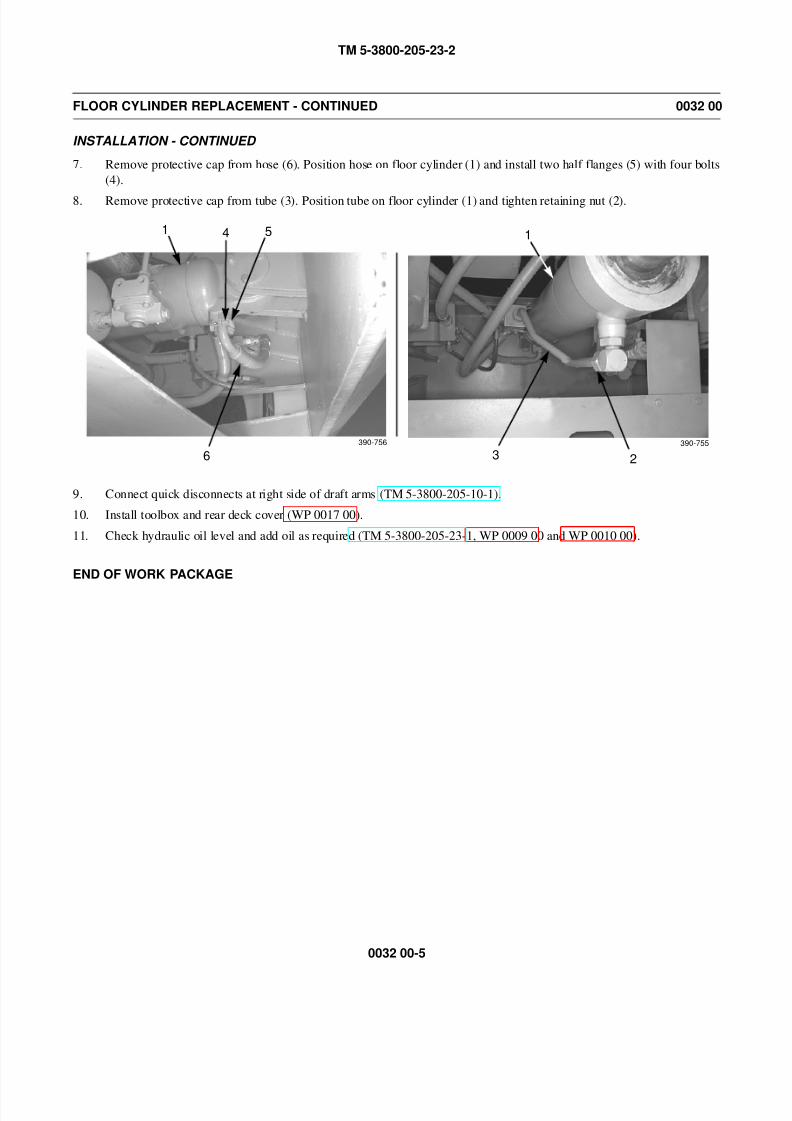
8/14/2019 TM 5-3800-205-23-2 MODEL 613CS
http://slidepdf.com/reader/full/tm-5-3800-205-23-2-model-613cs 157/276
TM 5-3800-205-23-2
0032 00-5
FLOOR CYLINDER REPLACEMENT - CONTINUED 0032 00
INSTALLATION - CONTINUED
7. Remove protective cap from hose (6). Position hose on floor cylinder (1) and install two half flanges (5) with four bolts
(4).
8. Remove protective cap from tube (3). Position tube on floor cylinder (1) and tighten retaining nut (2).
9. Connect quick disconnects at right side of draft arms (TM 5-3800-205-10-1).
10. Install toolbox and rear deck cover (WP 0017 00).
11. Check hydraulic oil level and add oil as required (TM 5-3800-205-23-1, WP 0009 00 and WP 0010 00).
END OF WORK PACKAGE
1 4 5
6390-756
23
1
390-755

8/14/2019 TM 5-3800-205-23-2 MODEL 613CS
http://slidepdf.com/reader/full/tm-5-3800-205-23-2-model-613cs 158/276
TM 5-3800-205-23-2
0032 00-6
This Page Intentionally Left Blank.
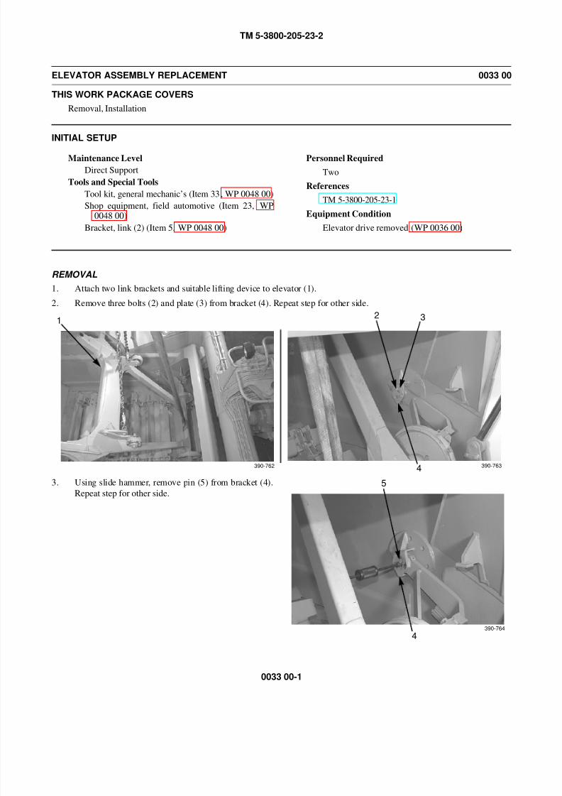
8/14/2019 TM 5-3800-205-23-2 MODEL 613CS
http://slidepdf.com/reader/full/tm-5-3800-205-23-2-model-613cs 159/276
TM 5-3800-205-23-2
0033 00-1
ELEVATOR ASSEMBLY REPLACEMENT 0033 00
THIS WORK PACKAGE COVERS
Removal, Installation
INITIAL SETUP
Maintenance Level
Direct Support
Tools and Special Tools
Tool kit, general mechanic’s (Item 33, WP 0048 00)
Shop equipment, field automotive (Item 23, WP0048 00)
Bracket, link (2) (Item 5, WP 0048 00)
Personnel Required
Two
References
TM 5-3800-205-23-1
Equipment Condition
Elevator drive removed (WP 0036 00)
REMOVAL1. Attach two link brackets and suitable lifting device to elevator (1).
2. Remove three bolts (2) and plate (3) from bracket (4). Repeat step for other side.
3. Using slide hammer, remove pin (5) from bracket (4).
Repeat step for other side.
12 3
4390-762 390-763
4
5
390-764
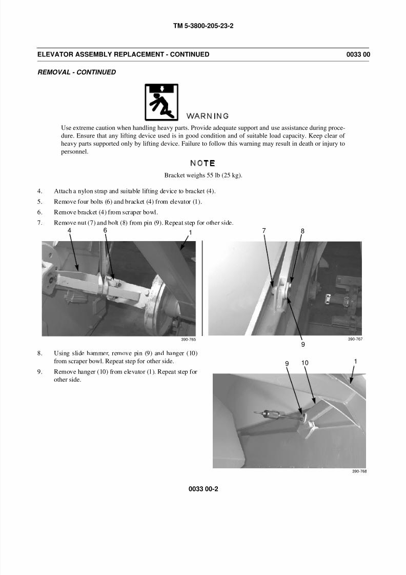
8/14/2019 TM 5-3800-205-23-2 MODEL 613CS
http://slidepdf.com/reader/full/tm-5-3800-205-23-2-model-613cs 160/276
TM 5-3800-205-23-2
0033 00-2
ELEVATOR ASSEMBLY REPLACEMENT - CONTINUED 0033 00
REMOVAL - CONTINUED
WARNING
Use extreme caution when handling heavy parts. Provide adequate support and use assistance during proce-
dure. Ensure that any lifting device used is in good condition and of suitable load capacity. Keep clear of
heavy parts supported only by lifting device. Failure to follow this warning may result in death or injury to
personnel.
NOTE
Bracket weighs 55 lb (25 kg).
4. Attach a nylon strap and suitable lifting device to bracket (4).
5. Remove four bolts (6) and bracket (4) from elevator (1).
6. Remove bracket (4) from scraper bowl.
7. Remove nut (7) and bolt (8) from pin (9). Repeat step for other side.
8. Using slide hammer, remove pin (9) and hanger (10)
from scraper bowl. Repeat step for other side.
9. Remove hanger (10) from elevator (1). Repeat step for
other side.
4 6 1 8
9
7
390-765 390-767
9 10
390-768
1

8/14/2019 TM 5-3800-205-23-2 MODEL 613CS
http://slidepdf.com/reader/full/tm-5-3800-205-23-2-model-613cs 161/276
TM 5-3800-205-23-2
0033 00-3
ELEVATOR ASSEMBLY REPLACEMENT - CONTINUED 0033 00
REMOVAL - CONTINUED
WARNING
Use extreme caution when handling heavy parts. Provide adequate support and use assistance during proce-
dure. Ensure that any lifting device used is in good condition and of suitable lift capacity. Keep clear of
heavy parts supported only by lifting device. Failure to follow this warning may result in death or injury to
personnel.
NOTE
Elevator weighs 1050 lb (475 kg).
10. Remove elevator (1) from scraper bowl.
INSTALLATION
WARNING
Use extreme caution when handling heavy parts. Provide adequate support and use assistance during proce-
dure. Ensure that any lifting device used is in good condition and of suitable lift capacity. Keep clear of
heavy parts supported only by lifting device. Failure to follow this warning may result in death or injury to
personnel.
NOTE
Elevator weighs 1050 lb (475 kg).
1. Position elevator (1) on scraper bowl and install hanger (10). Repeat step for other side.
2. Clean and lubricate pin (9). Position hanger (10) on scraper bowl and install pin using a soft-faced hammer. Install bolt
(8) and nut (7) in pin. Repeat step for other side.
NOTE
Bracket weighs 55 lb (25 kg).
3. Install bracket (4) on scraper bowl with four bolts (6). Remove lifting device and nylon strap from bracket. Repeat stepfor other side.
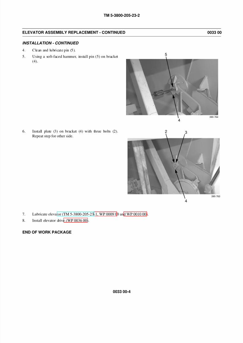
8/14/2019 TM 5-3800-205-23-2 MODEL 613CS
http://slidepdf.com/reader/full/tm-5-3800-205-23-2-model-613cs 162/276
TM 5-3800-205-23-2
0033 00-4
ELEVATOR ASSEMBLY REPLACEMENT - CONTINUED 0033 00
INSTALLATION - CONTINUED
4. Clean and lubricate pin (5).
5. Using a soft-faced hammer, install pin (5) on bracket
(4).
6. Install plate (3) on bracket (4) with three bolts (2).
Repeat step for other side.
7. Lubricate elevator (TM 5-3800-205-23-1, WP 0009 00 and WP 0010 00).
8. Install elevator drive (WP 0036 00).
END OF WORK PACKAGE
4
5
390-764
2 3
4
390-763

8/14/2019 TM 5-3800-205-23-2 MODEL 613CS
http://slidepdf.com/reader/full/tm-5-3800-205-23-2-model-613cs 163/276
TM 5-3800-205-23-2
0034 00-1
ELEVATOR CHAIN IDLER REPAIR 0034 00
THIS WORK PACKAGE COVERS
Disassembly, Cleaning and Inspection, Assembly
INITIAL SETUP
Maintenance Level
Direct Support
Tools and Special Tools
Tool kit, general mechanic’s (Item 33, WP 0048 00)
Driver set (Item 7, WP 0048 00)
Materials/Parts
Grease, GAA (Item 16, WP 0047 00)
Seal, lip
Equipment Condition
Elevator chain idler removed (WP 0026 00)
DISASSEMBLY
1. Remove nut (2) and bracket (1) from roller (3).
2. Remove four shims (4) and shield (5) from roller (3).
3. Remove four bolts (6) and cap (7) from roller (3).
1
390-784
3
2
3
3
390-785
4
5
3
390-786
76
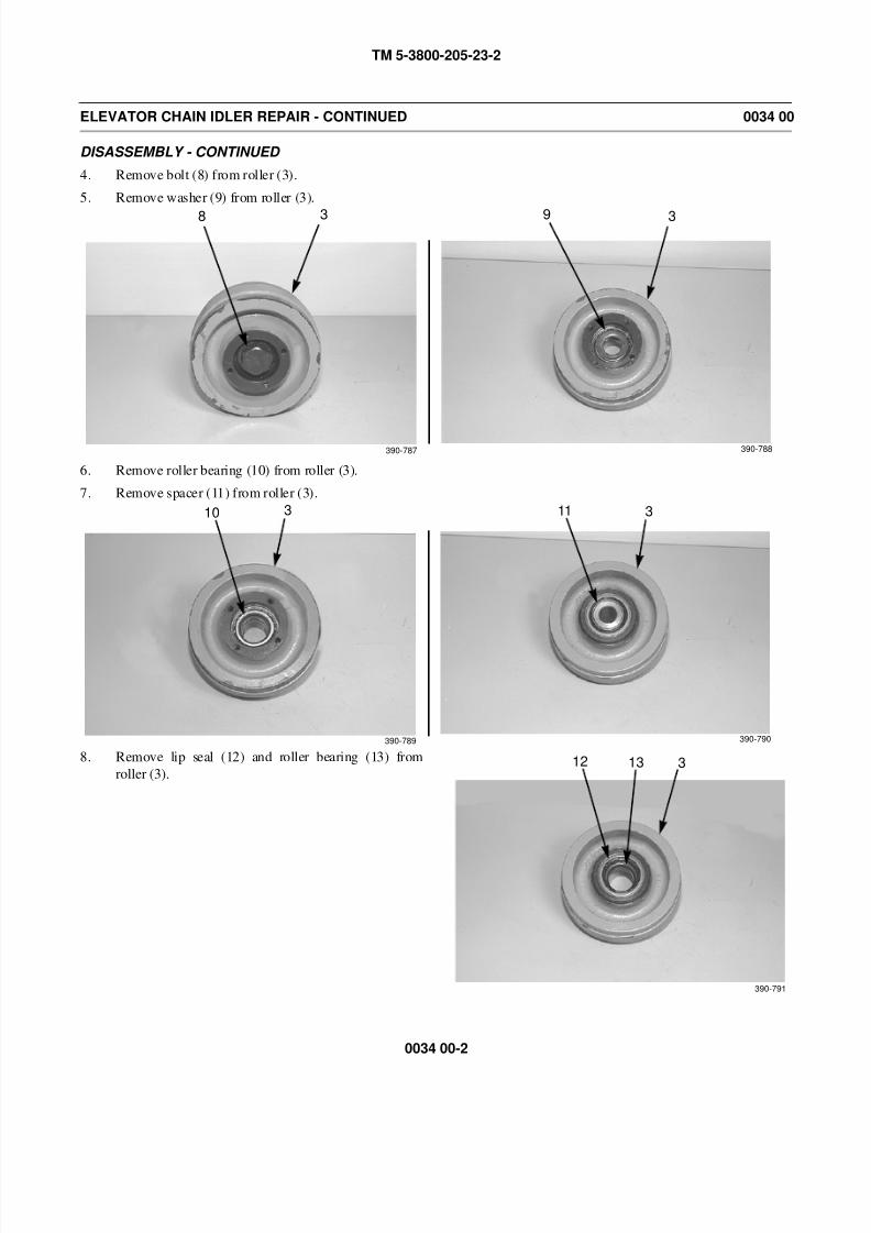
8/14/2019 TM 5-3800-205-23-2 MODEL 613CS
http://slidepdf.com/reader/full/tm-5-3800-205-23-2-model-613cs 164/276
TM 5-3800-205-23-2
0034 00-2
ELEVATOR CHAIN IDLER REPAIR - CONTINUED 0034 00
DISASSEMBLY - CONTINUED
4. Remove bolt (8) from roller (3).
5. Remove washer (9) from roller (3).
6. Remove roller bearing (10) from roller (3).
7. Remove spacer (11) from roller (3).
8. Remove lip seal (12) and roller bearing (13) from
roller (3).
3
390-787
8 3
390-788
9
310 3
390-790
11
390-789
3
390-791
12 13
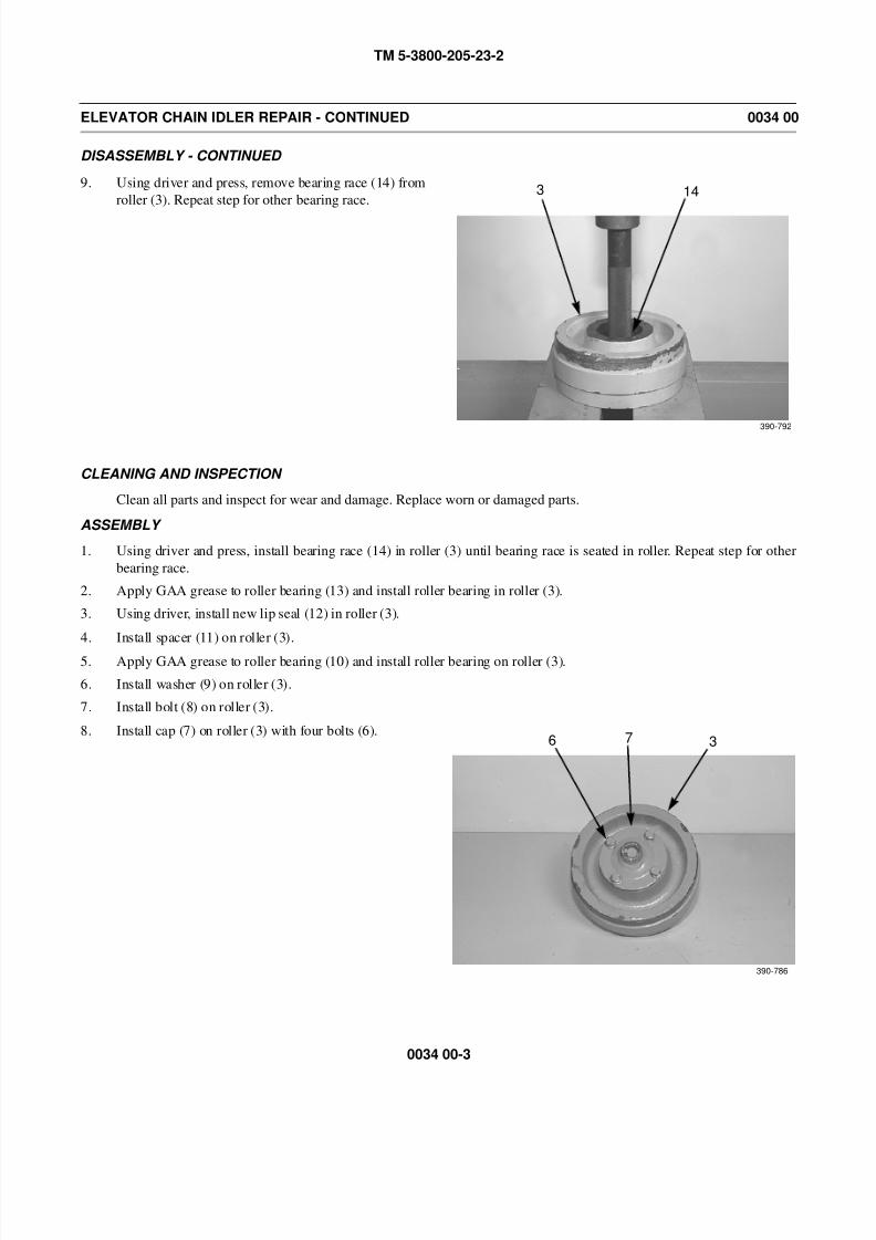
8/14/2019 TM 5-3800-205-23-2 MODEL 613CS
http://slidepdf.com/reader/full/tm-5-3800-205-23-2-model-613cs 165/276
TM 5-3800-205-23-2
0034 00-3
ELEVATOR CHAIN IDLER REPAIR - CONTINUED 0034 00
DISASSEMBLY - CONTINUED
9. Using driver and press, remove bearing race (14) from
roller (3). Repeat step for other bearing race.
CLEANING AND INSPECTION
Clean all parts and inspect for wear and damage. Replace worn or damaged parts.
ASSEMBLY
1. Using driver and press, install bearing race (14) in roller (3) until bearing race is seated in roller. Repeat step for other
bearing race.
2. Apply GAA grease to roller bearing (13) and install roller bearing in roller (3).
3. Using driver, install new lip seal (12) in roller (3).
4. Install spacer (11) on roller (3).
5. Apply GAA grease to roller bearing (10) and install roller bearing on roller (3).
6. Install washer (9) on roller (3).
7. Install bolt (8) on roller (3).
8. Install cap (7) on roller (3) with four bolts (6).
390-792
3 14
3
390-786
76
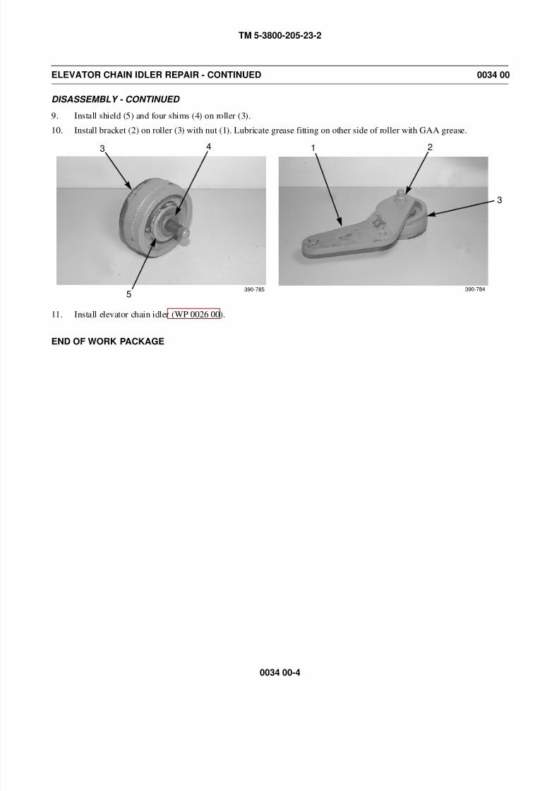
8/14/2019 TM 5-3800-205-23-2 MODEL 613CS
http://slidepdf.com/reader/full/tm-5-3800-205-23-2-model-613cs 166/276
TM 5-3800-205-23-2
0034 00-4
ELEVATOR CHAIN IDLER REPAIR - CONTINUED 0034 00
DISASSEMBLY - CONTINUED
9. Install shield (5) and four shims (4) on roller (3).
10. Install bracket (2) on roller (3) with nut (1). Lubricate grease fitting on other side of roller with GAA grease.
11. Install elevator chain idler (WP 0026 00).
END OF WORK PACKAGE
3
390-785
4
5
1
390-784
2
3
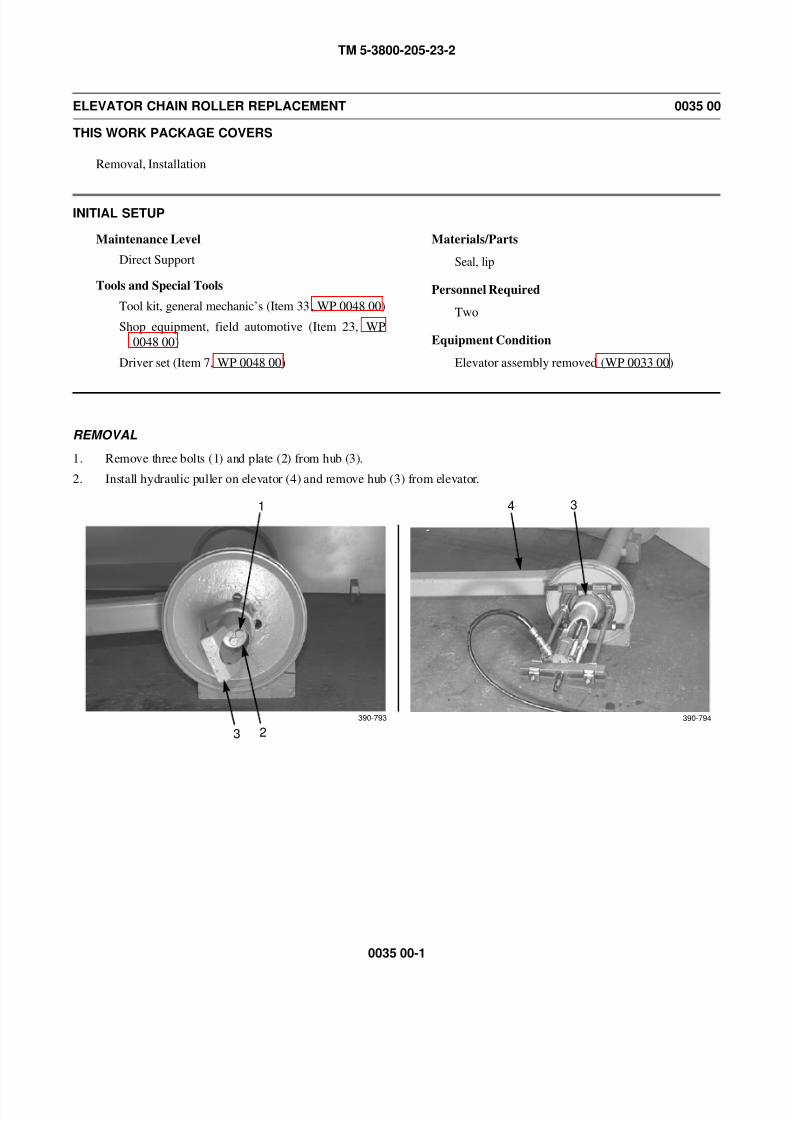
8/14/2019 TM 5-3800-205-23-2 MODEL 613CS
http://slidepdf.com/reader/full/tm-5-3800-205-23-2-model-613cs 167/276
TM 5-3800-205-23-2
0035 00-1
ELEVATOR CHAIN ROLLER REPLACEMENT 0035 00
THIS WORK PACKAGE COVERS
Removal, Installation
INITIAL SETUP
Maintenance Level
Direct Support
Tools and Special Tools
Tool kit, general mechanic’s (Item 33, WP 0048 00)
Shop equipment, field automotive (Item 23, WP
0048 00)
Driver set (Item 7, WP 0048 00)
Materials/Parts
Seal, lip
Personnel Required
Two
Equipment Condition
Elevator assembly removed (WP 0033 00)
REMOVAL
1. Remove three bolts (1) and plate (2) from hub (3).
2. Install hydraulic puller on elevator (4) and remove hub (3) from elevator.
1
23
34
390-793 390-794

8/14/2019 TM 5-3800-205-23-2 MODEL 613CS
http://slidepdf.com/reader/full/tm-5-3800-205-23-2-model-613cs 168/276
TM 5-3800-205-23-2
0035 00-2
ELEVATOR CHAIN ROLLER MAINTENANCE - CONTINUED 0035 00
REMOVAL - CONTINUED
3. Remove key (7) and shims (5) from shaft (6).
WARNING
Use extreme caution when handling heavy parts. Provide adequate support and use assistance during proce-
dure. Ensure that any lifting device used is in good condition and of suitable lift capacity. Keep clear of
heavy parts supported only by lifting device. Failure to follow this warning may result in death or injury to
personnel.
NOTE
Roller weighs 75 lb (34 kg).
4. With assistance, remove roller (8) from shaft (6).
5. Remove shims (9) from shaft (6).
7
5
6
390-795
8
6
9
6390-796 390-797
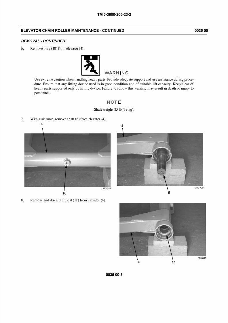
8/14/2019 TM 5-3800-205-23-2 MODEL 613CS
http://slidepdf.com/reader/full/tm-5-3800-205-23-2-model-613cs 169/276
TM 5-3800-205-23-2
0035 00-3
ELEVATOR CHAIN ROLLER MAINTENANCE - CONTINUED 0035 00
REMOVAL - CONTINUED
6. Remove plug (10) from elevator (4).
WARNING
Use extreme caution when handling heavy parts. Provide adequate support and use assistance during proce-
dure. Ensure that any lifting device used is in good condition and of suitable lift capacity. Keep clear of
heavy parts supported only by lifting device. Failure to follow this warning may result in death or injury to
personnel.
NOTE
Shaft weighs 85 lb (39 kg).
7. With assistance, remove shaft (6) from elevator (4).
8. Remove and discard lip seal (11) from elevator (4).
4
10
4
6
390-798 390-799
4 11
390-800
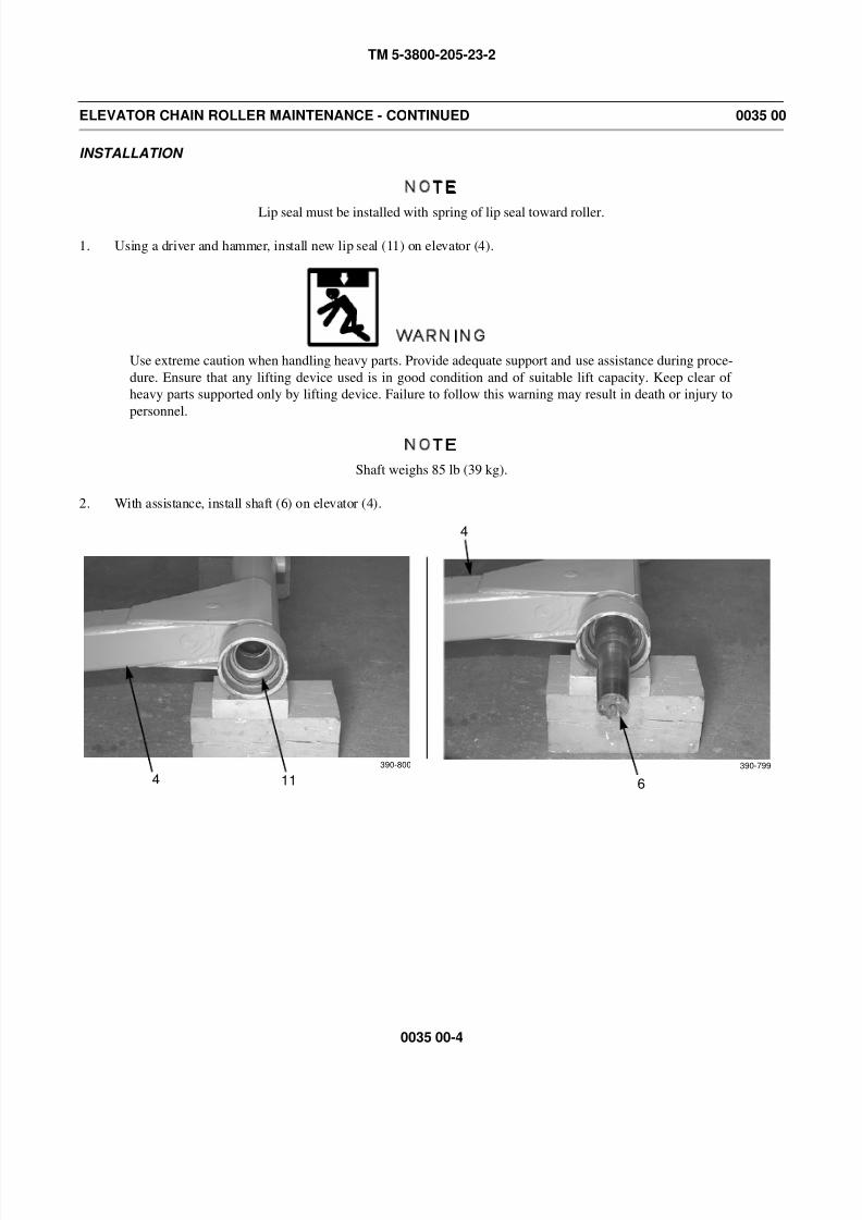
8/14/2019 TM 5-3800-205-23-2 MODEL 613CS
http://slidepdf.com/reader/full/tm-5-3800-205-23-2-model-613cs 170/276
TM 5-3800-205-23-2
0035 00-4
ELEVATOR CHAIN ROLLER MAINTENANCE - CONTINUED 0035 00
INSTALLATION
NOTE
Lip seal must be installed with spring of lip seal toward roller.
1. Using a driver and hammer, install new lip seal (11) on elevator (4).
WARNING
Use extreme caution when handling heavy parts. Provide adequate support and use assistance during proce-
dure. Ensure that any lifting device used is in good condition and of suitable lift capacity. Keep clear of
heavy parts supported only by lifting device. Failure to follow this warning may result in death or injury to
personnel.
NOTE
Shaft weighs 85 lb (39 kg).
2. With assistance, install shaft (6) on elevator (4).
4
6
390-799
4 11
390-800

8/14/2019 TM 5-3800-205-23-2 MODEL 613CS
http://slidepdf.com/reader/full/tm-5-3800-205-23-2-model-613cs 171/276
TM 5-3800-205-23-2
0035 00-5
ELEVATOR CHAIN ROLLER MAINTENANCE - CONTINUED 0035 00
INSTALLATION - CONTINUED
3. Install plug (10) on elevator (4). Do NOT tighten plug.
4. With assistance, install roller (8) on elevator. Push roller against elevator (4).
5. Determine correct number of shims (9) by subtracting distance between rollers from 47 in. (11.94 cm) measuring
between center of each roller.
6. Install roller (8) on elevator (4). Tighten plug (10).
7. Install number of shims (9) required (determined in step 5) on shaft (6).
8. Install roller (8) and hub (3) on elevator (4).
4
10
390-798
8
6
390-796
9
6390-797
4 8
3390-803
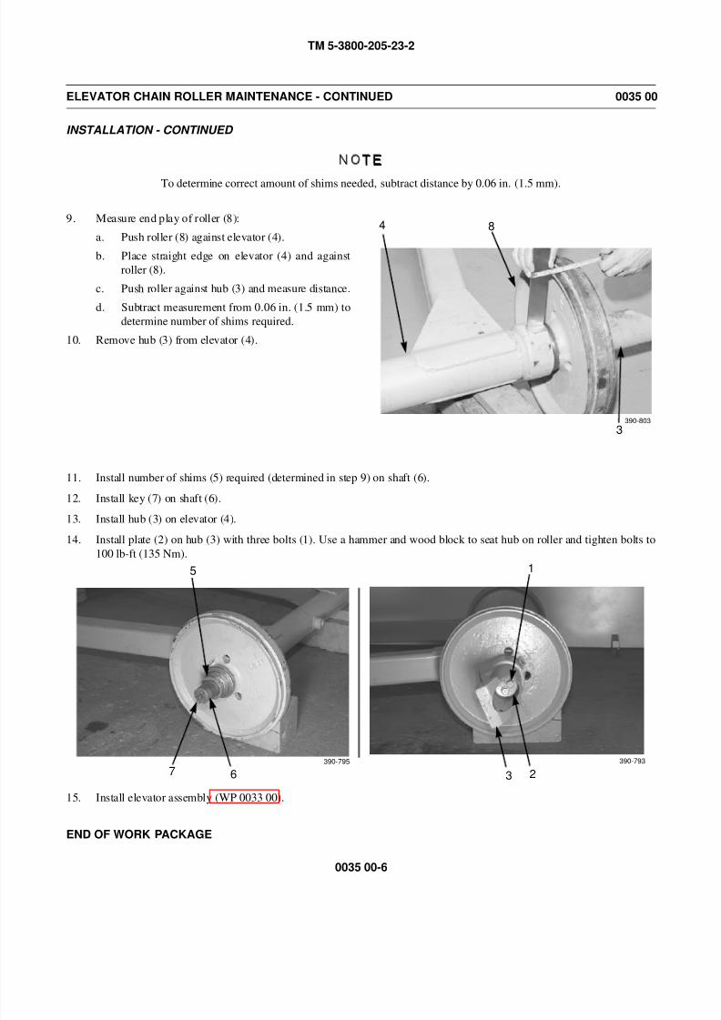
8/14/2019 TM 5-3800-205-23-2 MODEL 613CS
http://slidepdf.com/reader/full/tm-5-3800-205-23-2-model-613cs 172/276
TM 5-3800-205-23-2
0035 00-6
ELEVATOR CHAIN ROLLER MAINTENANCE - CONTINUED 0035 00
INSTALLATION - CONTINUED
NOTE
To determine correct amount of shims needed, subtract distance by 0.06 in. (1.5 mm).
9. Measure end play of roller (8):
a. Push roller (8) against elevator (4).
b. Place straight edge on elevator (4) and against
roller (8).
c. Push roller against hub (3) and measure distance.
d. Subtract measurement from 0.06 in. (1.5 mm) to
determine number of shims required.
10. Remove hub (3) from elevator (4).
11. Install number of shims (5) required (determined in step 9) on shaft (6).
12. Install key (7) on shaft (6).
13. Install hub (3) on elevator (4).
14. Install plate (2) on hub (3) with three bolts (1). Use a hammer and wood block to seat hub on roller and tighten bolts to100 lb-ft (135 Nm).
15. Install elevator assembly (WP 0033 00).
END OF WORK PACKAGE
4 8
3390-803
7
5
6
390-795
1
23
390-793
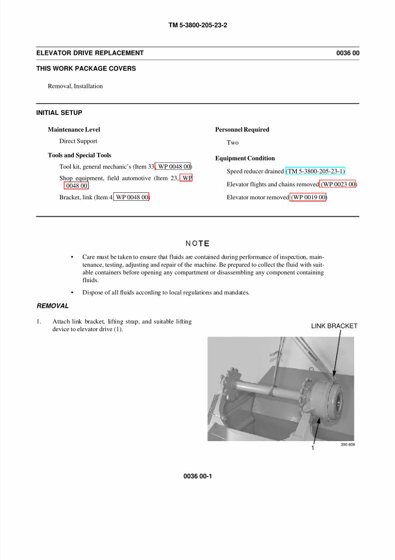
8/14/2019 TM 5-3800-205-23-2 MODEL 613CS
http://slidepdf.com/reader/full/tm-5-3800-205-23-2-model-613cs 173/276
TM 5-3800-205-23-2
0036 00-1
ELEVATOR DRIVE REPLACEMENT 0036 00
THIS WORK PACKAGE COVERS
Removal, Installation
INITIAL SETUP
Maintenance Level
Direct Support
Tools and Special Tools
Tool kit, general mechanic’s (Item 33, WP 0048 00)
Shop equipment, field automotive (Item 23, WP
0048 00)
Bracket, link (Item 4, WP 0048 00)
Personnel Required
Two
Equipment Condition
Speed reducer drained (TM 5-3800-205-23-1)
Elevator flights and chains removed (WP 0023 00)
Elevator motor removed (WP 0019 00)
NOTE
• Care must be taken to ensure that fluids are contained during performance of inspection, main-
tenance, testing, adjusting and repair of the machine. Be prepared to collect the fluid with suit-
able containers before opening any compartment or disassembling any component containing
fluids.
• Dispose of all fluids according to local regulations and mandates.
REMOVAL
1. Attach link bracket, lifting strap, and suitable lifting
device to elevator drive (1).
1
LINK BRACKET
390-806
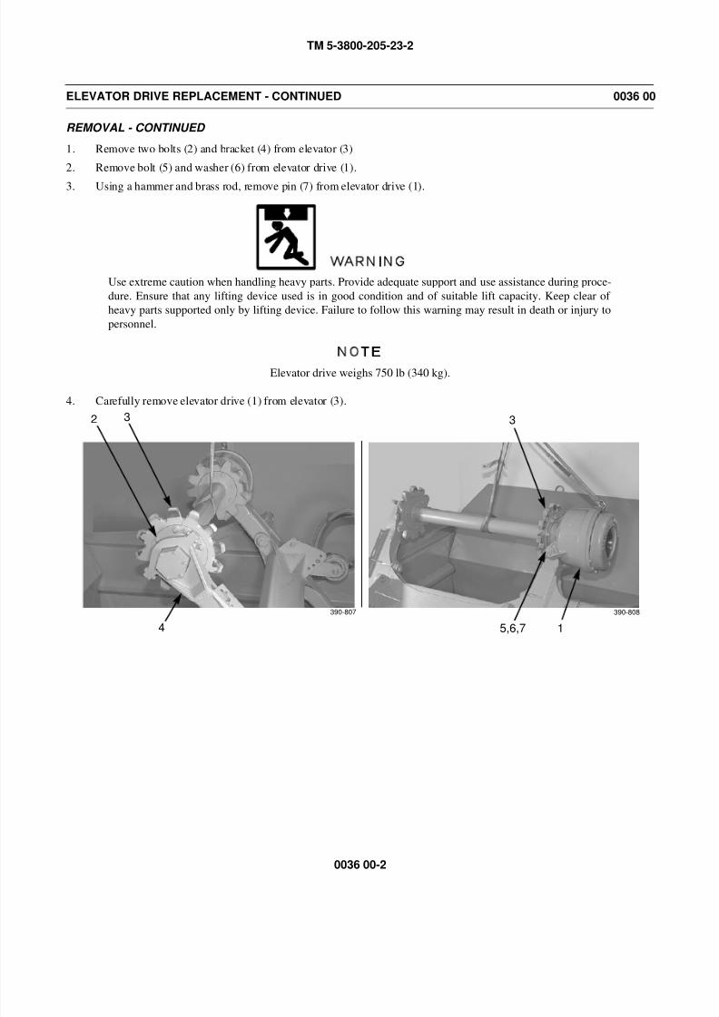
8/14/2019 TM 5-3800-205-23-2 MODEL 613CS
http://slidepdf.com/reader/full/tm-5-3800-205-23-2-model-613cs 174/276
TM 5-3800-205-23-2
0036 00-2
ELEVATOR DRIVE REPLACEMENT - CONTINUED 0036 00
REMOVAL - CONTINUED
1. Remove two bolts (2) and bracket (4) from elevator (3)
2. Remove bolt (5) and washer (6) from elevator drive (1).
3. Using a hammer and brass rod, remove pin (7) from elevator drive (1).
WARNING
Use extreme caution when handling heavy parts. Provide adequate support and use assistance during proce-
dure. Ensure that any lifting device used is in good condition and of suitable lift capacity. Keep clear of
heavy parts supported only by lifting device. Failure to follow this warning may result in death or injury to
personnel.
NOTEElevator drive weighs 750 lb (340 kg).
4. Carefully remove elevator drive (1) from elevator (3).
2
4
3
15,6,7
390-807 390-808
3
8/14/2019 TM 5-3800-205-23-2 MODEL 613CS
http://slidepdf.com/reader/full/tm-5-3800-205-23-2-model-613cs 175/276
TM 5-3800-205-23-2
0036 00-3
ELEVATOR DRIVE REPLACEMENT - CONTINUED 0036 00
INSTALLATION
WARNING
Use extreme caution when handling heavy parts. Provide adequate support and use assistance during proce-
dure. Ensure that any lifting device used is in good condition and of suitable lift capacity. Keep clear of
heavy parts supported only by lifting device. Failure to follow this warning may result in death or injury to
personnel.
NOTE
Elevator drive weighs 750 lb (340 kg).
1. Position elevator drive (1) on elevator (3) and using soft-faced hammer, install pin (7).
2. Install washer (6) and bolt (5) on elevator drive (1).
3. Install bracket (4) on elevator (3) with two bolts (2).
4. Fill speed reducer (TM 5-3800-205-23-1, WP 0009 00 and WP 0010 00).
5. Install elevator motor (WP 0019 00).
6. Install elevator flights and chains (WP 0023 00).
END OF WORK PACKAGE

8/14/2019 TM 5-3800-205-23-2 MODEL 613CS
http://slidepdf.com/reader/full/tm-5-3800-205-23-2-model-613cs 176/276
TM 5-3800-205-23-2
0036 00-4
This Page Intentionally Left Blank.
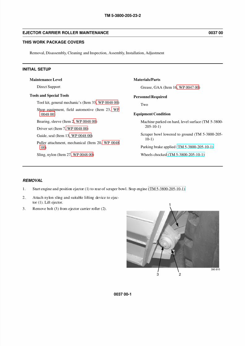
8/14/2019 TM 5-3800-205-23-2 MODEL 613CS
http://slidepdf.com/reader/full/tm-5-3800-205-23-2-model-613cs 177/276
TM 5-3800-205-23-2
0037 00-1
EJECTOR CARRIER ROLLER MAINTENANCE 0037 00
THIS WORK PACKAGE COVERS
Removal, Disassembly, Cleaning and Inspection, Assembly, Installation, Adjustment
INITIAL SETUP
Maintenance Level
Direct Support
Tools and Special Tools
Tool kit, general mechanic’s (Item 33, WP 0048 00)
Shop equipment, field automotive (Item 23, WP
0048 00)
Bearing, sleeve (Item 2, WP 0048 00)
Driver set (Item 7, WP 0048 00)
Guide, seal (Item 13, WP 0048 00)
Puller attachment, mechanical (Item 20, WP 0048
00)
Sling, nylon (Item 27, WP 0048 00)
Materials/Parts
Grease, GAA (Item 16, WP 0047 00)
Personnel Required
Two
Equipment Condition
Machine parked on hard, level surface (TM 5-3800-205-10-1)
Scraper bowl lowered to ground (TM 5-3800-205-
10-1)
Parking brake applied (TM 5-3800-205-10-1)
Wheels chocked (TM 5-3800-205-10-1)
REMOVAL
1. Start engine and position ejector (1) to rear of scraper bowl. Stop engine (TM 5-3800-205-10-1).
2. Attach nylon sling and suitable lifting device to ejec-
tor (1). Lift ejector.
3. Remove bolt (3) from ejector carrier roller (2).1
23
390-810
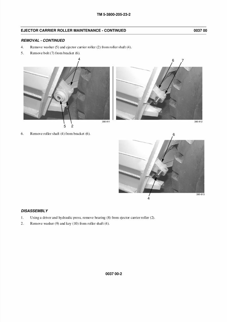
8/14/2019 TM 5-3800-205-23-2 MODEL 613CS
http://slidepdf.com/reader/full/tm-5-3800-205-23-2-model-613cs 178/276
TM 5-3800-205-23-2
0037 00-2
EJECTOR CARRIER ROLLER MAINTENANCE - CONTINUED 0037 00
REMOVAL - CONTINUED
4. Remove washer (5) and ejector carrier roller (2) from roller shaft (4).
5. Remove bolt (7) from bracket (6).
6. Remove roller shaft (4) from bracket (6).
DISASSEMBLY
1. Using a driver and hydraulic press, remove bearing (8) from ejector carrier roller (2).
2. Remove washer (9) and key (10) from roller shaft (4).
5 2
4
390-811 390-812
6 7
4
6
390-813
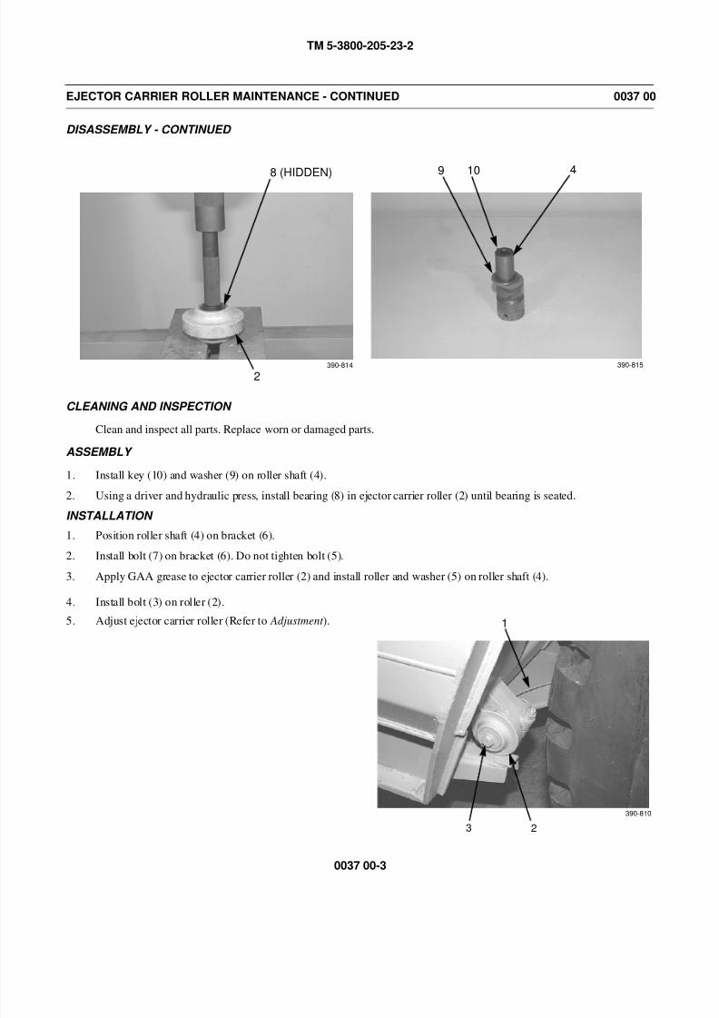
8/14/2019 TM 5-3800-205-23-2 MODEL 613CS
http://slidepdf.com/reader/full/tm-5-3800-205-23-2-model-613cs 179/276
TM 5-3800-205-23-2
0037 00-3
EJECTOR CARRIER ROLLER MAINTENANCE - CONTINUED 0037 00
DISASSEMBLY - CONTINUED
CLEANING AND INSPECTION
Clean and inspect all parts. Replace worn or damaged parts.
ASSEMBLY
1. Install key (10) and washer (9) on roller shaft (4).
2. Using a driver and hydraulic press, install bearing (8) in ejector carrier roller (2) until bearing is seated.
INSTALLATION
1. Position roller shaft (4) on bracket (6).
2. Install bolt (7) on bracket (6). Do not tighten bolt (5).
3. Apply GAA grease to ejector carrier roller (2) and install roller and washer (5) on roller shaft (4).
4. Install bolt (3) on roller (2).
5. Adjust ejector carrier roller (Refer to Adjustment ).
2
8 (HIDDEN)
390-814
9 10 4
390-815
1
23
390-810
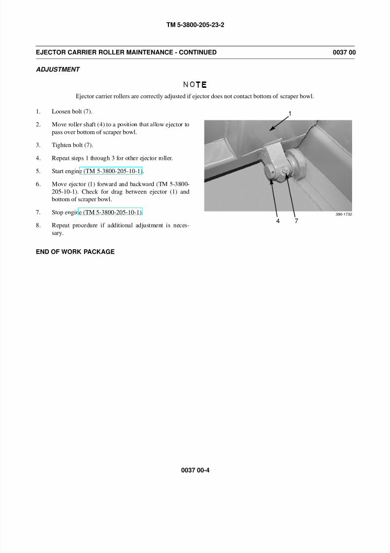
8/14/2019 TM 5-3800-205-23-2 MODEL 613CS
http://slidepdf.com/reader/full/tm-5-3800-205-23-2-model-613cs 180/276
TM 5-3800-205-23-2
0037 00-4
EJECTOR CARRIER ROLLER MAINTENANCE - CONTINUED 0037 00
ADJUSTMENT
NOTE
Ejector carrier rollers are correctly adjusted if ejector does not contact bottom of scraper bowl.
1. Loosen bolt (7).
2. Move roller shaft (4) to a position that allow ejector to
pass over bottom of scraper bowl.
3. Tighten bolt (7).
4. Repeat steps 1 through 3 for other ejector roller.
5. Start engine (TM 5-3800-205-10-1).
6. Move ejector (1) forward and backward (TM 5-3800-
205-10-1). Check for drag between ejector (1) andbottom of scraper bowl.
7. Stop engine (TM 5-3800-205-10-1).
8. Repeat procedure if additional adjustment is neces-
sary.
END OF WORK PACKAGE
4 7390-1732
1
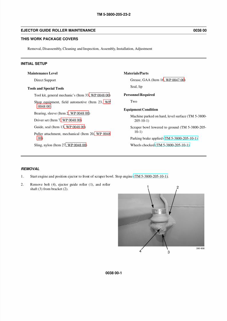
8/14/2019 TM 5-3800-205-23-2 MODEL 613CS
http://slidepdf.com/reader/full/tm-5-3800-205-23-2-model-613cs 181/276
TM 5-3800-205-23-2
0038 00-1
EJECTOR GUIDE ROLLER MAINTENANCE 0038 00
THIS WORK PACKAGE COVERS
Removal, Disassembly, Cleaning and Inspection, Assembly, Installation, Adjustment
INITIAL SETUP
Maintenance Level
Direct Support
Tools and Special Tools
Tool kit, general mechanic’s (Item 33, WP 0048 00)
Shop equipment, field automotive (Item 23, WP
0048 00)
Bearing, sleeve (Item 2, WP 0048 00)
Driver set (Item 7, WP 0048 00)
Guide, seal (Item 13, WP 0048 00)
Puller attachment, mechanical (Item 20, WP 0048
00)
Sling, nylon (Item 27, WP 0048 00)
Materials/Parts
Grease, GAA (Item 16, WP 0047 00)
Seal, lip
Personnel Required
Two
Equipment Condition
Machine parked on hard, level surface (TM 5-3800-
205-10-1)
Scraper bowl lowered to ground (TM 5-3800-205-
10-1)
Parking brake applied (TM 5-3800-205-10-1)
Wheels chocked (TM 5-3800-205-10-1)
REMOVAL
1. Start engine and position ejector to front of scraper bowl. Stop engine (TM 5-3800-205-10-1).
2. Remove bolt (4), ejector guide roller (1), and roller
shaft (3) from bracket (2).1 2
4 3390-908
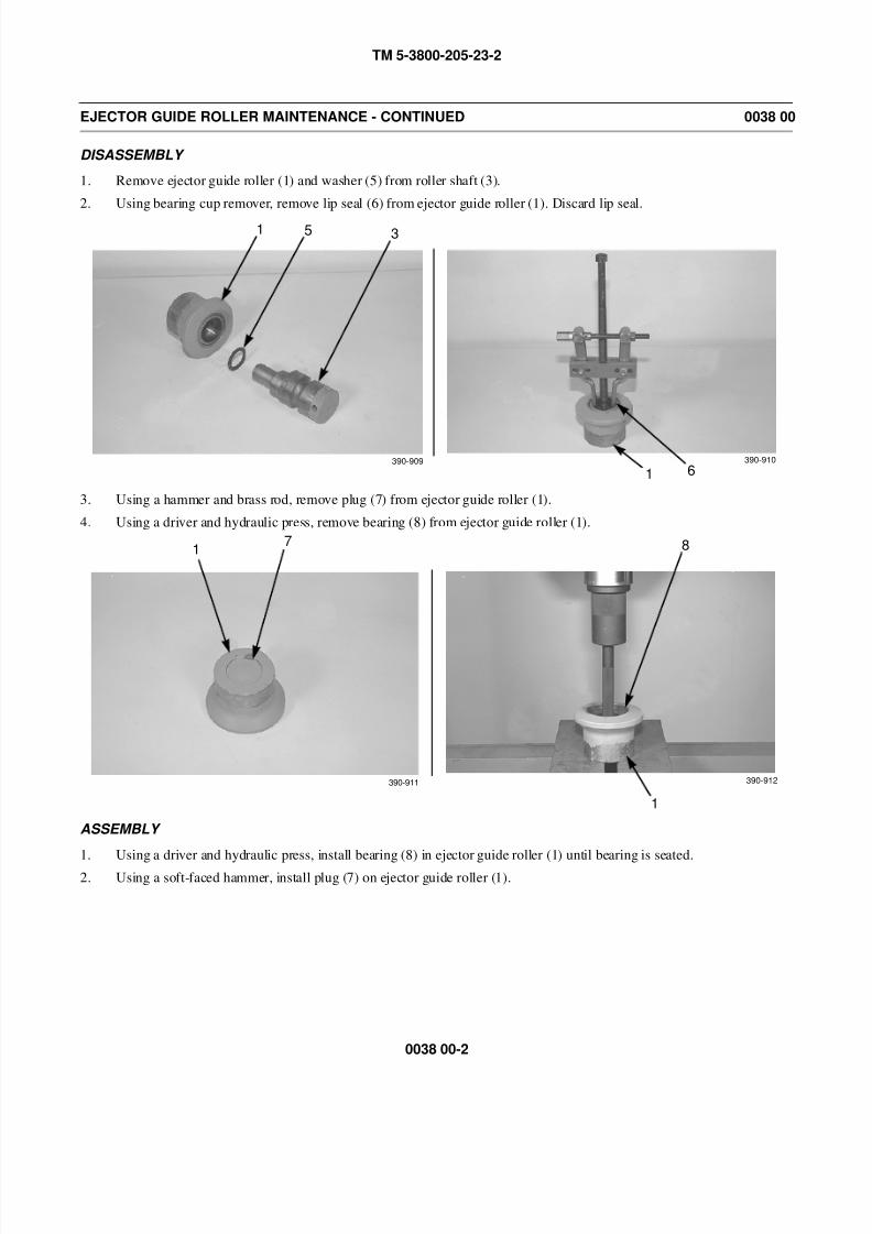
8/14/2019 TM 5-3800-205-23-2 MODEL 613CS
http://slidepdf.com/reader/full/tm-5-3800-205-23-2-model-613cs 182/276
TM 5-3800-205-23-2
0038 00-2
EJECTOR GUIDE ROLLER MAINTENANCE - CONTINUED 0038 00
DISASSEMBLY
1. Remove ejector guide roller (1) and washer (5) from roller shaft (3).
2. Using bearing cup remover, remove lip seal (6) from ejector guide roller (1). Discard lip seal.
3. Using a hammer and brass rod, remove plug (7) from ejector guide roller (1).
4. Using a driver and hydraulic press, remove bearing (8) from ejector guide roller (1).
ASSEMBLY
1. Using a driver and hydraulic press, install bearing (8) in ejector guide roller (1) until bearing is seated.
2. Using a soft-faced hammer, install plug (7) on ejector guide roller (1).
1 5 3
61390-909 390-910
17 8
1
390-911 390-912
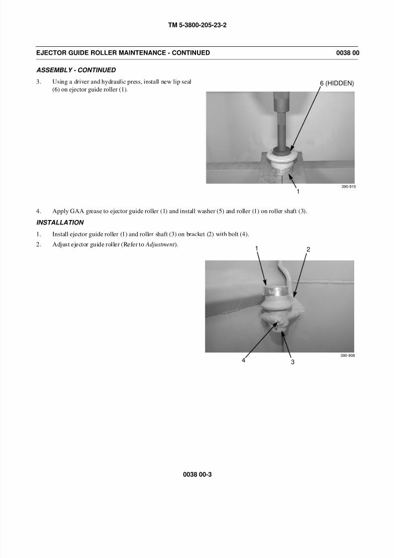
8/14/2019 TM 5-3800-205-23-2 MODEL 613CS
http://slidepdf.com/reader/full/tm-5-3800-205-23-2-model-613cs 183/276
TM 5-3800-205-23-2
0038 00-3
EJECTOR GUIDE ROLLER MAINTENANCE - CONTINUED 0038 00
ASSEMBLY - CONTINUED
3. Using a driver and hydraulic press, install new lip seal
(6) on ejector guide roller (1).
4. Apply GAA grease to ejector guide roller (1) and install washer (5) and roller (1) on roller shaft (3).
INSTALLATION
1. Install ejector guide roller (1) and roller shaft (3) on bracket (2) with bolt (4).
2. Adjust ejector guide roller (Refer to Adjustment ).
1
6 (HIDDEN)
390-915
1 2
4 3390-908

8/14/2019 TM 5-3800-205-23-2 MODEL 613CS
http://slidepdf.com/reader/full/tm-5-3800-205-23-2-model-613cs 184/276
TM 5-3800-205-23-2
0038 00-4
EJECTOR GUIDE ROLLER MAINTENANCE - CONTINUED 0038 00
ADJUSTMENT
NOTE
Ejector guide rollers are correctly adjusted if ejector does not contact sides of scraper bowl. Ejector guiderollers should be in a position that prevents ejector from rising too far above the floor of scraper bowl.
1. Loosen bolt (9).
2. Move roller shaft (3) to a position that allows ejector
to pass over sides of scraper bowl.
3. Tighten bolt (9).
4. Repeat steps 1 through 3 for other ejector guide roller.
5. Start engine (TM 5-3800-205-10-1).
6. Move ejector forward and backward (TM 5-3800-205-
10-1). Check for drag between ejector and sides of
scraper bowl.
7. Stop engine (TM 5-3800-205-10-1).
8. Repeat procedure if additional adjustment is neces-
sary.
END OF WORK PACKAGE
9 3
390-1733
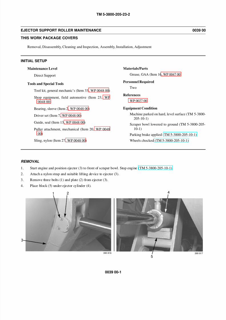
8/14/2019 TM 5-3800-205-23-2 MODEL 613CS
http://slidepdf.com/reader/full/tm-5-3800-205-23-2-model-613cs 185/276
TM 5-3800-205-23-2
0039 00-1
EJECTOR SUPPORT ROLLER MAINTENANCE 0039 00
THIS WORK PACKAGE COVERS
Removal, Disassembly, Cleaning and Inspection, Assembly, Installation, Adjustment
INITIAL SETUP
Maintenance Level
Direct Support
Tools and Special Tools
Tool kit, general mechanic’s (Item 33, WP 0048 00)
Shop equipment, field automotive (Item 23, WP
0048 00)
Bearing, sleeve (Item 2, WP 0048 00)
Driver set (Item 7, WP 0048 00)
Guide, seal (Item 13, WP 0048 00)
Puller attachment, mechanical (Item 20, WP 0048
00)
Sling, nylon (Item 27, WP 0048 00)
Materials/Parts
Grease, GAA (Item 16, WP 0047 00)
Personnel Required
Two
References
WP 0027 00
Equipment Condition
Machine parked on hard, level surface (TM 5-3800-
205-10-1)
Scraper bowl lowered to ground (TM 5-3800-205-
10-1)
Parking brake applied (TM 5-3800-205-10-1)
Wheels chocked (TM 5-3800-205-10-1)
REMOVAL
1. Start engine and position ejector (3) to front of scraper bowl. Stop engine (TM 5-3800-205-10-1).
2. Attach a nylon strap and suitable lifting device to ejector (3).
3. Remove three bolts (1) and plate (2) from ejector (3).
4. Place block (5) under ejector cylinder (4).
1 2
3
390-916 390-917
4
5
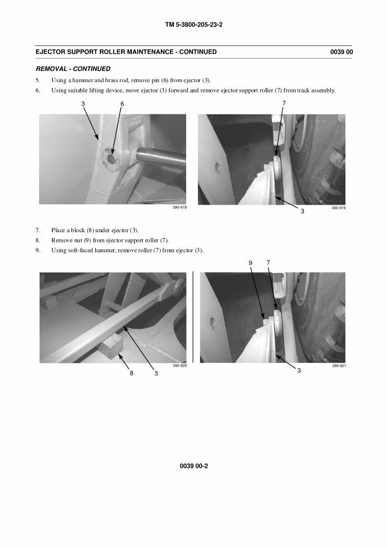
8/14/2019 TM 5-3800-205-23-2 MODEL 613CS
http://slidepdf.com/reader/full/tm-5-3800-205-23-2-model-613cs 186/276
TM 5-3800-205-23-2
0039 00-2
EJECTOR SUPPORT ROLLER MAINTENANCE - CONTINUED 0039 00
REMOVAL - CONTINUED
5. Using a hammer and brass rod, remove pin (6) from ejector (3).
6. Using suitable lifting device, move ejector (3) forward and remove ejector support roller (7) from track assembly.
7. Place a block (8) under ejector (3).
8. Remove nut (9) from ejector support roller (7).
9. Using soft-faced hammer, remove roller (7) from ejector (3).
3 6
390-918 390-919
7
3
8 3
390-920 390-921
9 7
3

8/14/2019 TM 5-3800-205-23-2 MODEL 613CS
http://slidepdf.com/reader/full/tm-5-3800-205-23-2-model-613cs 187/276
TM 5-3800-205-23-2
0039 00-3
EJECTOR SUPPORT ROLLER MAINTENANCE - CONTINUED 0039 00
DISASSEMBLY
1. Remove key (10) from ejector support roller (7).
2. Remove retaining ring (11) from ejector support roller (7).
3. Using a driver and hydraulic press, remove plug (12) and roller shaft (13) from ejector support roller (7).
4. Remove roller bearing (14) from roller shaft (13).
CLEANING AND INSPECTION
Clean and inspect all parts. Replace worn or damaged parts.
ASSEMBLY
1. Apply GAA grease to roller bearing (14) and install roller bearing on roller shaft (13).
2. Using a driver, seal guide, sleeve bearing, and hydraulic press, install plug (12) and roller shaft (13) on ejector support
roller (7) until roller shaft is seated in roller.
3. Install retaining ring (11) on ejector support roller (7).
4. Install key (10) on ejector support roller (7).
107 7 11
390-923 390-924
12 (HIDDEN)
713390-925 390-926
13 14
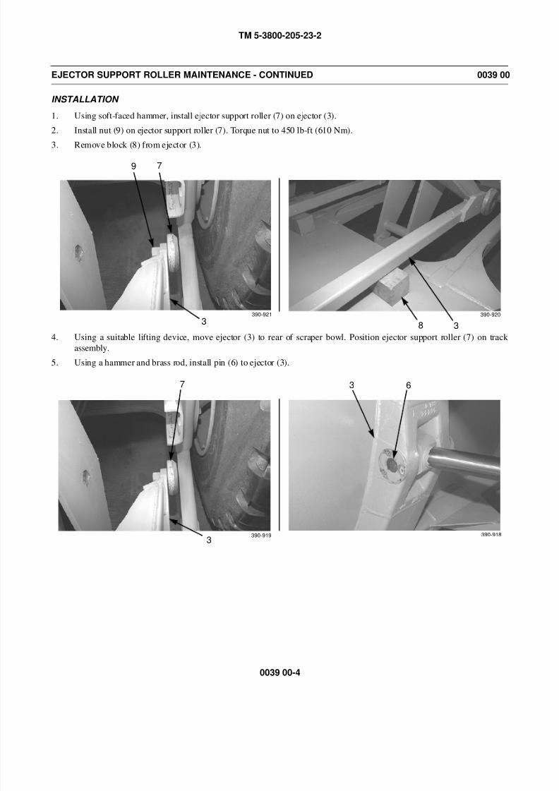
8/14/2019 TM 5-3800-205-23-2 MODEL 613CS
http://slidepdf.com/reader/full/tm-5-3800-205-23-2-model-613cs 188/276
TM 5-3800-205-23-2
0039 00-4
EJECTOR SUPPORT ROLLER MAINTENANCE - CONTINUED 0039 00
INSTALLATION
1. Using soft-faced hammer, install ejector support roller (7) on ejector (3).
2. Install nut (9) on ejector support roller (7). Torque nut to 450 lb-ft (610 Nm).
3. Remove block (8) from ejector (3).
4. Using a suitable lifting device, move ejector (3) to rear of scraper bowl. Position ejector support roller (7) on track
assembly.
5. Using a hammer and brass rod, install pin (6) to ejector (3).
390-921
9 7
3 8 3
390-920
390-919
7
3
3 6
390-918
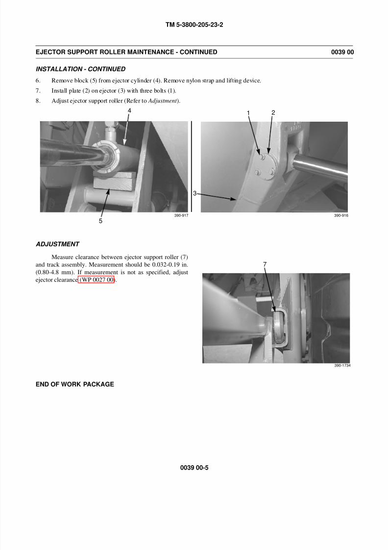
8/14/2019 TM 5-3800-205-23-2 MODEL 613CS
http://slidepdf.com/reader/full/tm-5-3800-205-23-2-model-613cs 189/276
TM 5-3800-205-23-2
0039 00-5
EJECTOR SUPPORT ROLLER MAINTENANCE - CONTINUED 0039 00
INSTALLATION - CONTINUED
6. Remove block (5) from ejector cylinder (4). Remove nylon strap and lifting device.
7. Install plate (2) on ejector (3) with three bolts (1).
8. Adjust ejector support roller (Refer to Adjustment ).
ADJUSTMENT
Measure clearance between ejector support roller (7)
and track assembly. Measurement should be 0.032-0.19 in.
(0.80-4.8 mm). If measurement is not as specified, adjust
ejector clearance (WP 0027 00).
END OF WORK PACKAGE
390-917
4
5
1 2
3
390-916
7
390-1734

8/14/2019 TM 5-3800-205-23-2 MODEL 613CS
http://slidepdf.com/reader/full/tm-5-3800-205-23-2-model-613cs 190/276
TM 5-3800-205-23-2
0039 00-6
This Page Intentionally Left Blank.
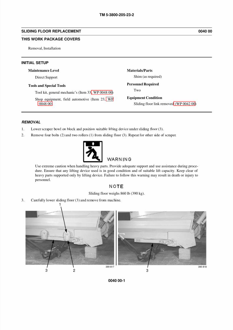
8/14/2019 TM 5-3800-205-23-2 MODEL 613CS
http://slidepdf.com/reader/full/tm-5-3800-205-23-2-model-613cs 191/276
TM 5-3800-205-23-2
0040 00-1
SLIDING FLOOR REPLACEMENT 0040 00
THIS WORK PACKAGE COVERS
Removal, Installation
INITIAL SETUP
Maintenance Level
Direct Support
Tools and Special Tools
Tool kit, general mechanic’s (Item 33, WP 0048 00)
Shop equipment, field automotive (Item 23, WP
0048 00)
Materials/Parts
Shim (as required)
Personnel Required
Two
Equipment Condition
Sliding floor link removed (WP 0042 00)
REMOVAL
1. Lower scraper bowl on block and position suitable lifting device under sliding floor (3).
2. Remove four bolts (2) and two rollers (1) from sliding floor (3). Repeat for other side of scraper.
WARNING
Use extreme caution when handling heavy parts. Provide adequate support and use assistance during proce-
dure. Ensure that any lifting device used is in good condition and of suitable lift capacity. Keep clear of
heavy parts supported only by lifting device. Failure to follow this warning may result in death or injury to
personnel.
NOTE
Sliding floor weighs 860 lb (390 kg).
3. Carefully lower sliding floor (3) and remove from machine.
1
23 3390-817 390-818
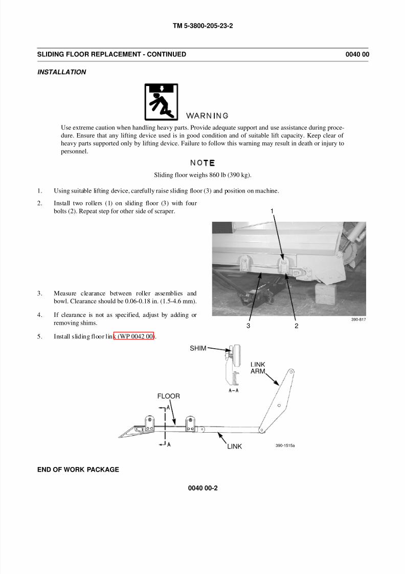
8/14/2019 TM 5-3800-205-23-2 MODEL 613CS
http://slidepdf.com/reader/full/tm-5-3800-205-23-2-model-613cs 192/276
TM 5-3800-205-23-2
0040 00-2
SLIDING FLOOR REPLACEMENT - CONTINUED 0040 00
INSTALLATION
WARNING
Use extreme caution when handling heavy parts. Provide adequate support and use assistance during proce-
dure. Ensure that any lifting device used is in good condition and of suitable lift capacity. Keep clear of
heavy parts supported only by lifting device. Failure to follow this warning may result in death or injury to
personnel.
NOTE
Sliding floor weighs 860 lb (390 kg).
1. Using suitable lifting device, carefully raise sliding floor (3) and position on machine.
2. Install two rollers (1) on sliding floor (3) with four
bolts (2). Repeat step for other side of scraper.
3. Measure clearance between roller assemblies and
bowl. Clearance should be 0.06-0.18 in. (1.5-4.6 mm).
4. If clearance is not as specified, adjust by adding or
removing shims.
5. Install sliding floor link (WP 0042 00).
END OF WORK PACKAGE
1
23390-817
SHIM
LINKARM
LINK
FLOOR
390-1515a
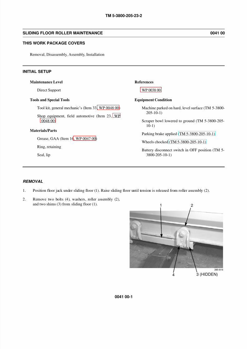
8/14/2019 TM 5-3800-205-23-2 MODEL 613CS
http://slidepdf.com/reader/full/tm-5-3800-205-23-2-model-613cs 193/276
TM 5-3800-205-23-2
0041 00-1
SLIDING FLOOR ROLLER MAINTENANCE 0041 00
THIS WORK PACKAGE COVERS
Removal, Disassembly, Assembly, Installation
INITIAL SETUP
Maintenance Level
Direct Support
Tools and Special Tools
Tool kit, general mechanic’s (Item 33, WP 0048 00)
Shop equipment, field automotive (Item 23, WP
0048 00)
Materials/Parts
Grease, GAA (Item 16, WP 0047 00)
Ring, retaining
Seal, lip
References
WP 0038 00
Equipment Condition
Machine parked on hard, level surface (TM 5-3800-
205-10-1)
Scraper bowl lowered to ground (TM 5-3800-205-10-1)
Parking brake applied (TM 5-3800-205-10-1)
Wheels chocked (TM 5-3800-205-10-1)
Battery disconnect switch in OFF position (TM 5-
3800-205-10-1)
REMOVAL
1. Position floor jack under sliding floor (1). Raise sliding floor until tension is released from roller assembly (2).
2. Remove two bolts (4), washers, roller assembly (2),
and two shims (3) from sliding floor (1). 1 2
4 3 (HIDDEN)
390-819

8/14/2019 TM 5-3800-205-23-2 MODEL 613CS
http://slidepdf.com/reader/full/tm-5-3800-205-23-2-model-613cs 194/276
TM 5-3800-205-23-2
0041 00-2
SLIDING FLOOR ROLLER REPLACEMENT - CONTINUED 0041 00
DISASSEMBLY
1. Bend lockwasher (7) away from nut (5) and remove nut and lockwasher from roller bracket (6).
2. Remove grease fitting (8).
3. Remove roller assembly (2) from roller bracket (6).
4. Remove washer (9), key (10), and spacer (11) from roller assembly (2).
5. Using a puller, remove and discard lip seal (12) from roller assembly (2).
5 6
7
2
6
390-820 390-821
8
9 10
11 2 12 2390-822 390-823
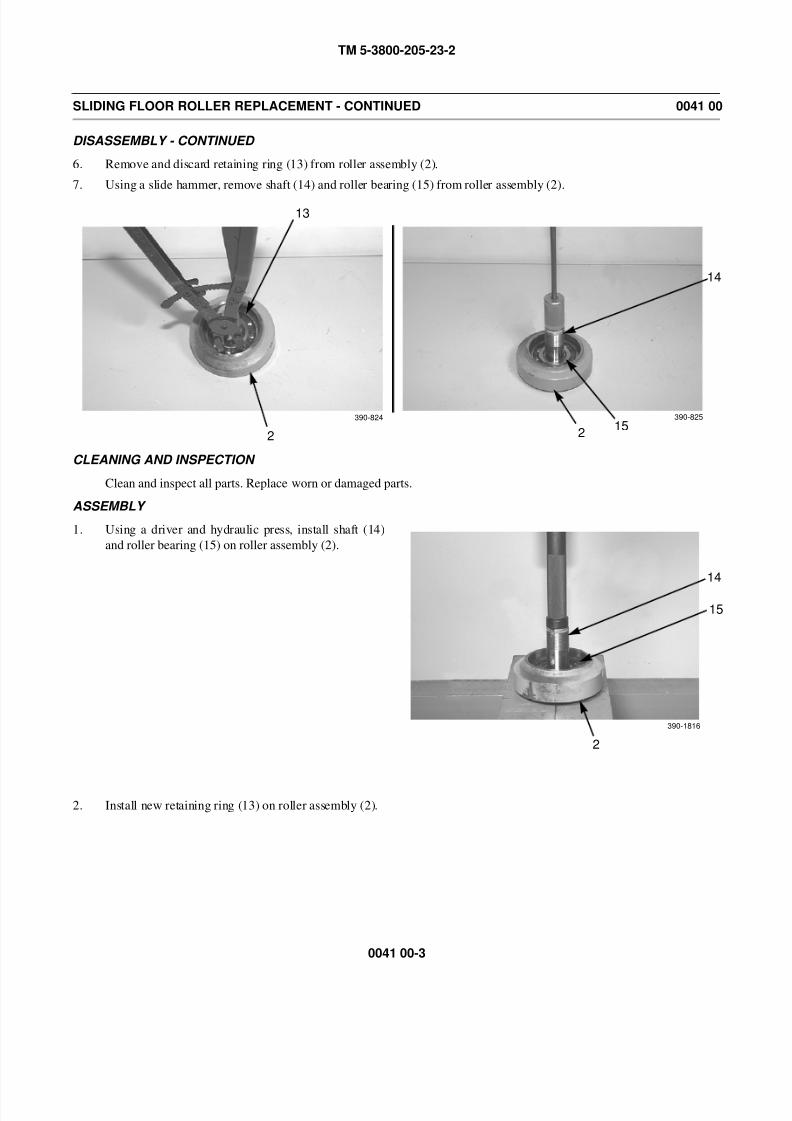
8/14/2019 TM 5-3800-205-23-2 MODEL 613CS
http://slidepdf.com/reader/full/tm-5-3800-205-23-2-model-613cs 195/276
TM 5-3800-205-23-2
0041 00-3
SLIDING FLOOR ROLLER REPLACEMENT - CONTINUED 0041 00
DISASSEMBLY - CONTINUED
6. Remove and discard retaining ring (13) from roller assembly (2).
7. Using a slide hammer, remove shaft (14) and roller bearing (15) from roller assembly (2).
CLEANING AND INSPECTION
Clean and inspect all parts. Replace worn or damaged parts.
ASSEMBLY
1. Using a driver and hydraulic press, install shaft (14)
and roller bearing (15) on roller assembly (2).
2. Install new retaining ring (13) on roller assembly (2).
13
2
14
215
390-824 390-825
14
2
15
390-1816
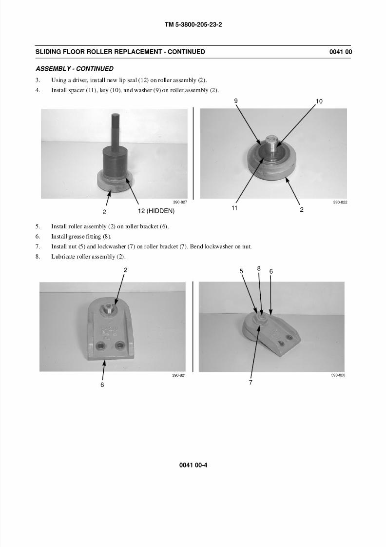
8/14/2019 TM 5-3800-205-23-2 MODEL 613CS
http://slidepdf.com/reader/full/tm-5-3800-205-23-2-model-613cs 196/276
TM 5-3800-205-23-2
0041 00-4
SLIDING FLOOR ROLLER REPLACEMENT - CONTINUED 0041 00
ASSEMBLY - CONTINUED
3. Using a driver, install new lip seal (12) on roller assembly (2).
4. Install spacer (11), key (10), and washer (9) on roller assembly (2).
5. Install roller assembly (2) on roller bracket (6).
6. Install grease fitting (8).
7. Install nut (5) and lockwasher (7) on roller bracket (7). Bend lockwasher on nut.
8. Lubricate roller assembly (2).
2 12 (HIDDEN)
9 10
11 2
390-822390-827
2
6
390-821
5 6
7
390-820
8
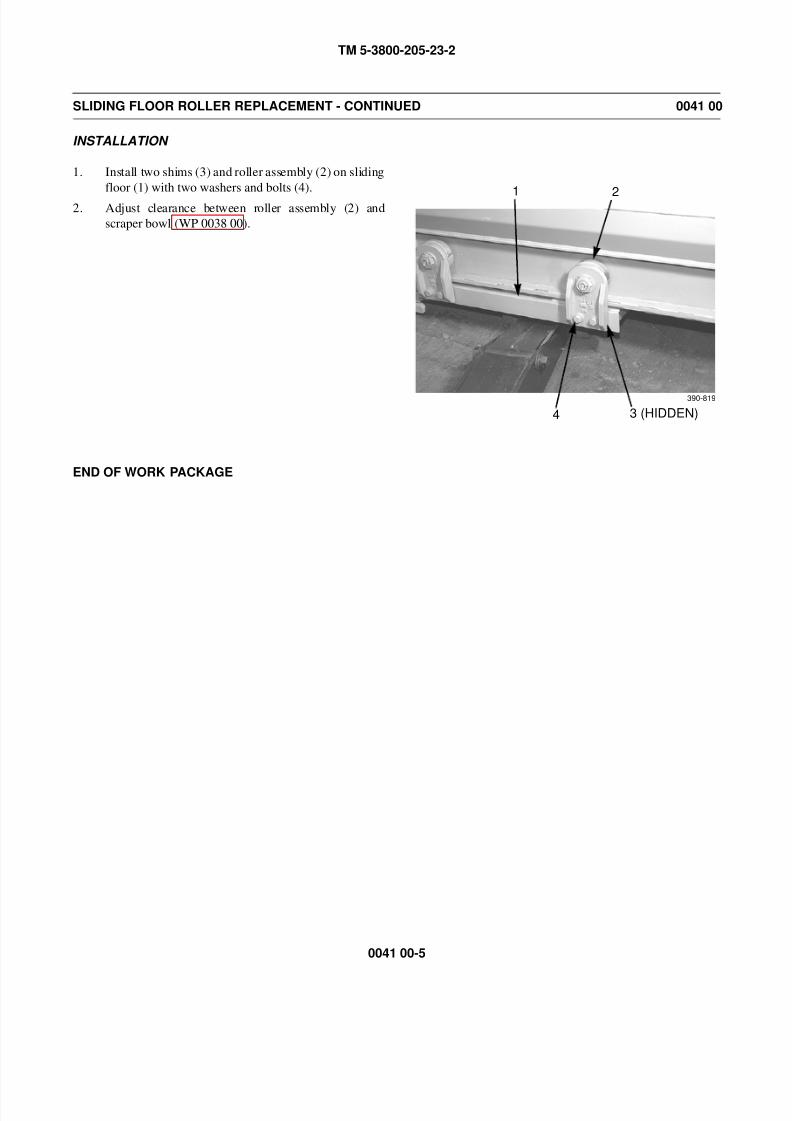
8/14/2019 TM 5-3800-205-23-2 MODEL 613CS
http://slidepdf.com/reader/full/tm-5-3800-205-23-2-model-613cs 197/276
TM 5-3800-205-23-2
0041 00-5
SLIDING FLOOR ROLLER REPLACEMENT - CONTINUED 0041 00
INSTALLATION
1. Install two shims (3) and roller assembly (2) on sliding
floor (1) with two washers and bolts (4).
2. Adjust clearance between roller assembly (2) and
scraper bowl (WP 0038 00).
END OF WORK PACKAGE
1 2
4 3 (HIDDEN)
390-819

8/14/2019 TM 5-3800-205-23-2 MODEL 613CS
http://slidepdf.com/reader/full/tm-5-3800-205-23-2-model-613cs 198/276
TM 5-3800-205-23-2
0041 00-6
This Page Intentionally Left Blank.

8/14/2019 TM 5-3800-205-23-2 MODEL 613CS
http://slidepdf.com/reader/full/tm-5-3800-205-23-2-model-613cs 199/276
TM 5-3800-205-23-2
0042 00-1
SLIDING FLOOR LINK REPLACEMENT 0042 00
THIS WORK PACKAGE COVERS
Removal, Installation
INITIAL SETUP
Maintenance Level
Direct Support
Tools and Special Tools
Tool kit, general mechanic’s (Item 33, WP 0048 00)
Shop equipment, field automotive (Item 23, WP
0048 00)
Equipment Condition
Machine parked on hard, level surface (TM 5-3800-
205-10-1)
Scraper bowl lowered to ground (TM 5-3800-205-
10-1)
Parking brake applied (TM 5-3800-205-10-1)
Wheels chocked (TM 5-3800-205-10-1)
Battery disconnect switch in OFF position (TM 5-
3800-205-10-1)
WARNING
Use extreme caution when handling heavy parts. Provide adequate support and use assistance during proce-
dure. Ensure that any lifting device used is in good condition and of suitable lift capacity. Keep clear of
heavy parts supported only by lifting device. Failure to follow this warning may result in death or injury to
personnel.
NOTE
Link assembly weighs 100 lb (45 kg).
1. Position floor jack under link assembly (1) and
remove two bolts (2), bar (3) and pin assembly (4).
Lower link assembly (1) to ground.
1 2
4
3
390-828
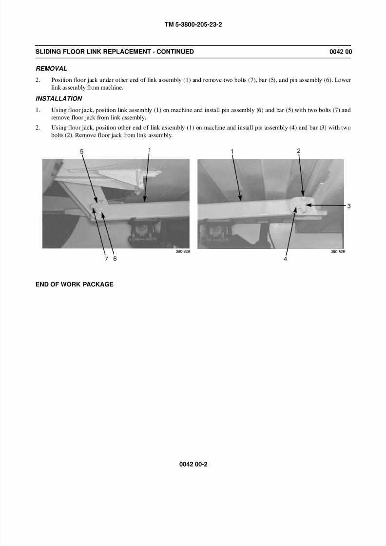
8/14/2019 TM 5-3800-205-23-2 MODEL 613CS
http://slidepdf.com/reader/full/tm-5-3800-205-23-2-model-613cs 200/276
TM 5-3800-205-23-2
0042 00-2
SLIDING FLOOR LINK REPLACEMENT - CONTINUED 0042 00
REMOVAL
2. Position floor jack under other end of link assembly (1) and remove two bolts (7), bar (5), and pin assembly (6). Lower
link assembly from machine.
INSTALLATION
1. Using floor jack, position link assembly (1) on machine and install pin assembly (6) and bar (5) with two bolts (7) and
remove floor jack from link assembly.
2. Using floor jack, position other end of link assembly (1) on machine and install pin assembly (4) and bar (3) with two
bolts (2). Remove floor jack from link assembly.
END OF WORK PACKAGE
7
5
6
1 1 2
4
3
390-828390-829
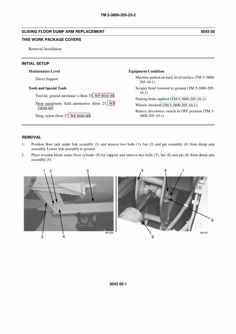
8/14/2019 TM 5-3800-205-23-2 MODEL 613CS
http://slidepdf.com/reader/full/tm-5-3800-205-23-2-model-613cs 201/276
TM 5-3800-205-23-2
0043 00-1
SLIDING FLOOR DUMP ARM REPLACEMENT 0043 00
THIS WORK PACKAGE COVERS
Removal, Installation
INITIAL SETUP
Maintenance Level
Direct Support
Tools and Special Tools
Tool kit, general mechanic’s (Item 33, WP 0048 00)
Shop equipment, field automotive (Item 23, WP
0048 00)
Sling, nylon (Item 27, WP 0048 00)
Equipment Condition
Machine parked on hard, level surface (TM 5-3800-
205-10-1)
Scraper bowl lowered to ground (TM 5-3800-205-
10-1)
Parking brake applied (TM 5-3800-205-10-1)
Wheels chocked (TM 5-3800-205-10-1)
Battery disconnect switch in OFF position (TM 5-
3800-205-10-1)
REMOVAL
1. Position floor jack under link assembly (3) and remove two bolts (1), bar (2) and pin assembly (4) from dump arm
assembly. Lower link assembly to ground.
2. Place wooden block under floor cylinder (9) for support and remove two bolts (7), bar (8) and pin (6) from dump arm
assembly (5).
7
9
1 2
4
3 6
390-829 390-831
8
5
5
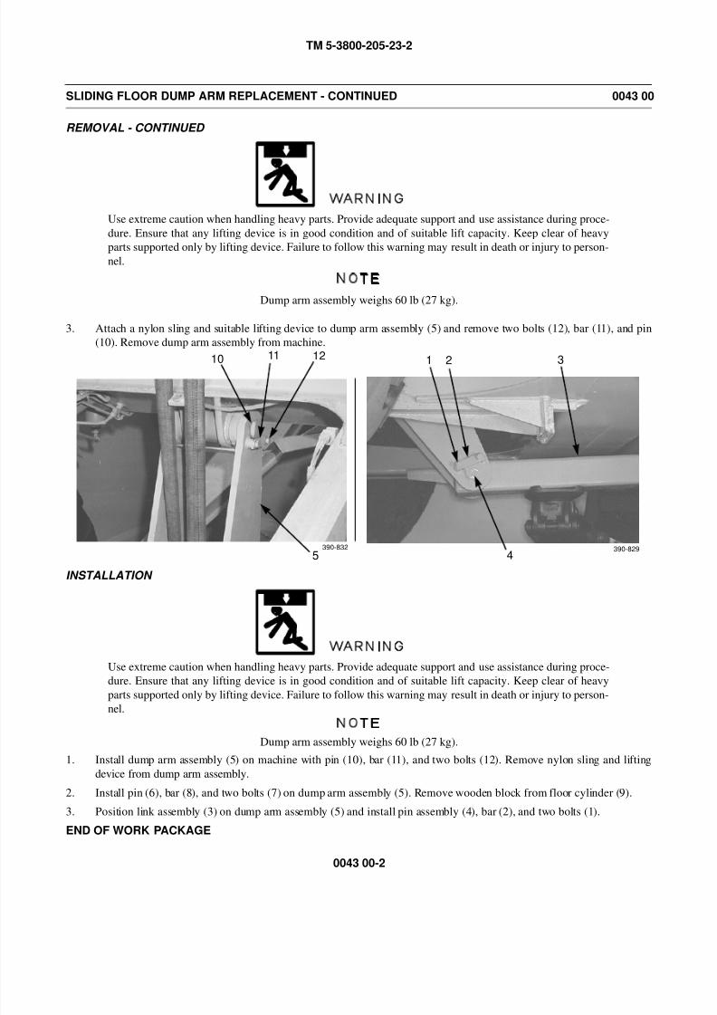
8/14/2019 TM 5-3800-205-23-2 MODEL 613CS
http://slidepdf.com/reader/full/tm-5-3800-205-23-2-model-613cs 202/276
TM 5-3800-205-23-2
0043 00-2
SLIDING FLOOR DUMP ARM REPLACEMENT - CONTINUED 0043 00
REMOVAL - CONTINUED
WARNING
Use extreme caution when handling heavy parts. Provide adequate support and use assistance during proce-
dure. Ensure that any lifting device is in good condition and of suitable lift capacity. Keep clear of heavy
parts supported only by lifting device. Failure to follow this warning may result in death or injury to person-
nel.
NOTE
Dump arm assembly weighs 60 lb (27 kg).
3. Attach a nylon sling and suitable lifting device to dump arm assembly (5) and remove two bolts (12), bar (11), and pin
(10). Remove dump arm assembly from machine.
INSTALLATION
WARNING
Use extreme caution when handling heavy parts. Provide adequate support and use assistance during proce-
dure. Ensure that any lifting device is in good condition and of suitable lift capacity. Keep clear of heavy
parts supported only by lifting device. Failure to follow this warning may result in death or injury to person-
nel.NOTE
Dump arm assembly weighs 60 lb (27 kg).
1. Install dump arm assembly (5) on machine with pin (10), bar (11), and two bolts (12). Remove nylon sling and lifting
device from dump arm assembly.
2. Install pin (6), bar (8), and two bolts (7) on dump arm assembly (5). Remove wooden block from floor cylinder (9).
3. Position link assembly (3) on dump arm assembly (5) and install pin assembly (4), bar (2), and two bolts (1).
END OF WORK PACKAGE
10 11
5
12 1 2
4
3
390-832 390-829

8/14/2019 TM 5-3800-205-23-2 MODEL 613CS
http://slidepdf.com/reader/full/tm-5-3800-205-23-2-model-613cs 203/276
TM 5-3800-205-23-2
CHAPTER 3
SUPPORTING INFORMATION

8/14/2019 TM 5-3800-205-23-2 MODEL 613CS
http://slidepdf.com/reader/full/tm-5-3800-205-23-2-model-613cs 204/276
TM 5-3800-205-23-2
This Page Intentionally Left Blank.
8/14/2019 TM 5-3800-205-23-2 MODEL 613CS
http://slidepdf.com/reader/full/tm-5-3800-205-23-2-model-613cs 205/276
TM 5-3800-205-23-2
0044 00-1
REFERENCES 0044 00
SCOPE
This work package lists all forms, field manuals, technical bulletins, technical manuals, and other publications refer-
enced in this manual and which apply to the operation of the scraper.
PUBLICATION INDEXES
The following indexes should be consulted frequently for latest changes or revisions and for new publications relating to
material covered in this technical manual.
Consolidated Army Publications and Forms Index. . . . . . . . . . . . . . . . . . . . . . . . . . . . . . . . . . . . . . . . . . . . . . . . .DA Pam 25-30
Consolidated Publication of Component Lists . . . . . . . . . . . . . . . . . . . . . . . . . . . . . . . . . . . . . . . . . . . . . . . . . . . . . . . . EM 0074
Functional User’s Manual for the Army Maintenance Management System. . . . . . . . . . . . . . . . . . . . . . . . . . .DA Pam 738-750
FORMS
Refer to DA Pam 738-750, The Army Maintenance Management System (TAMMS), for instructions on the use of main-tenance forms.
Equipment Inspection and Maintenance Worksheet . . . . . . . . . . . . . . . . . . . . . . . . . . . . . . . . DA Form 2404, DA Form 5988-E
Maintenance Request . . . . . . . . . . . . . . . . . . . . . . . . . . . . . . . . . . . . . . . . . . . . . . . . . . . . . . . . . . . . . . . . . . . . . . DA Form 2407
Material Receiving and Inspection Report . . . . . . . . . . . . . . . . . . . . . . . . . . . . . . . . . . . . . . . . . . . . . . . . . . . . . . . DD Form 250
Product Quality Deficiency Report. . . . . . . . . . . . . . . . . . . . . . . . . . . . . . . . . . . . . . . . . . . . . . . . . . . . . . . . . . . . . . SF Form 368
Recommended Changes to Publications and Blank Forms. . . . . . . . . . . . . . . . . . . . . . . . . . . . . . . . . . . . . . . . . . DA Form 2028
FIELD MANUALS
Airdrop of Supplies and Equipment . . . . . . . . . . . . . . . . . . . . . . . . . . . . . . . . . . . . . . . . . . . . . . . . . . . . . . . . . FM 10-576 Series
Basic Cold Weather Manual . . . . . . . . . . . . . . . . . . . . . . . . . . . . . . . . . . . . . . . . . . . . . . . . . . . . . . . . . . . . . . . . . . . . . .FM 31-70
Camouflage, Concealment, and Decoys . . . . . . . . . . . . . . . . . . . . . . . . . . . . . . . . . . . . . . . . . . . . . . . . . . . . . . . . . . . . . .FM 20-3
Chemical and Biological Contamination Avoidance . . . . . . . . . . . . . . . . . . . . . . . . . . . . . . . . . . . . . . . . . . . . . . . . . . . . .FM 3-3
Desert Operations . . . . . . . . . . . . . . . . . . . . . . . . . . . . . . . . . . . . . . . . . . . . . . . . . . . . . . . . . . . . . . . . . . . . . . . . . . . . . . .FM 90-3
First Aid for Soldiers. . . . . . . . . . . . . . . . . . . . . . . . . . . . . . . . . . . . . . . . . . . . . . . . . . . . . . . . . . . . . . . . . . . . . . . . . . . .FM 21-11
Manual for the Wheeled Vehicle Driver . . . . . . . . . . . . . . . . . . . . . . . . . . . . . . . . . . . . . . . . . . . . . . . . . . . . . . . . . . . .FM 21-305
Multiservice Helicopter Sling Load: Dual-Point Load Rigging Procedures. . . . . . . . . . . . . . . . . . . . . . . . . . . . . . . FM 10-450-5
NBC Decontamination . . . . . . . . . . . . . . . . . . . . . . . . . . . . . . . . . . . . . . . . . . . . . . . . . . . . . . . . . . . . . . . . . . . . . . . . . . . .FM 3-5
NBC Protection . . . . . . . . . . . . . . . . . . . . . . . . . . . . . . . . . . . . . . . . . . . . . . . . . . . . . . . . . . . . . . . . . . . . . . . . . . . . . . . . . . FM 3-4
Northern Operations . . . . . . . . . . . . . . . . . . . . . . . . . . . . . . . . . . . . . . . . . . . . . . . . . . . . . . . . . . . . . . . . . . . . . . . . . . . .FM 31-71
Nuclear Contamination Avoidance . . . . . . . . . . . . . . . . . . . . . . . . . . . . . . . . . . . . . . . . . . . . . . . . . . . . . . . . . . . . . . . . . FM 3-3-1
Operations and Maintenance of Ordnance Materiel in Cold Weather . . . . . . . . . . . . . . . . . . . . . . . . . . . . . . . . . . . . . .FM 9-207
Painting Instructions for Army Materiel . . . . . . . . . . . . . . . . . . . . . . . . . . . . . . . . . . . . . . . . . . . . . . . . . . . . . . . . . . .FM 43-0139
Unit Air Movement Planning . . . . . . . . . . . . . . . . . . . . . . . . . . . . . . . . . . . . . . . . . . . . . . . . . . . . . . . . . . . . . . . . . . . . . .FM 55-9
8/14/2019 TM 5-3800-205-23-2 MODEL 613CS
http://slidepdf.com/reader/full/tm-5-3800-205-23-2-model-613cs 206/276
TM 5-3800-205-23-2
0044 00-2
REFERENCES - CONTINUED 0044 00
TECHNICAL BULLETINS
CARC Spot Painting . . . . . . . . . . . . . . . . . . . . . . . . . . . . . . . . . . . . . . . . . . . . . . . . . . . . . . . . . . . . . . . . . . . . . . . . . . TB 43-0242
Color, Marking, and Camouflage Painting of Military Vehicles, Construction Equipment
and Materials Handling Equipment . . . . . . . . . . . . . . . . . . . . . . . . . . . . . . . . . . . . . . . . . . . . . . . . . . . . . . . . . . . TB 43-0209
TECHNICAL MANUALS
Care, Maintenance, Repair, and Inspection of Pneumatic Tires and Inner Tubes. . . . . . . . . . . . . . . . . . . . . . TM 9-2610-200-14
Destruction of Army Materiel to Prevent Enemy Use . . . . . . . . . . . . . . . . . . . . . . . . . . . . . . . . . . . . . . . . . . . . . . TM 750-244-6
Field Maintenance RPSTL for Scraper, Tractor, Elevating, Self-Propelled, 613CS and,
Distributor, Water, Tank Type, 613CWD. . . . . . . . . . . . . . . . . . . . . . . . . . . . . . . . . . . . . . . . . . . . . . . . TM 5-3800-205-23P
Operator’s Unit, Intermediate Direct Support, and Intermediate General Support
Maintenance Manual for Lead-Acid Storage Batteries . . . . . . . . . . . . . . . . . . . . . . . . . . . . . . . . . . . . . . TM 9-6140-200-14
Operator’s Manual for Scraper, Tractor, Elevating, Self-Propelled, 613CS. . . . . . . . . . . . . . . . . . . . . . . . TM 5-3800-205-10-1
Unit, Direct Support/General Support Maintenance Manual for Scraper, Tractor,
Elevating, Self-Propelled, 613CS and Distributor, Water, Tank Type, 613CWD . . . . . . . . . . . . . . . . TM 9-3800-205-23-1OTHER PUBLICATIONS
Abbreviations and Acronyms . . . . . . . . . . . . . . . . . . . . . . . . . . . . . . . . . . . . . . . . . . . . . . . . . . . . . . . . . . . . ASME Y14.38-1999
Army Medical Department Expendable/Durable Items . . . . . . . . . . . . . . . . . . . . . . . . . . . . . . . . . . . . . . . . . . . . . . . .CTA 8-100
Expendable/Durable Items (Except Medical, Class V, Repair Parts, and Heraldic Items). . . . . . . . . . . . . . . . . . . . . CTA 50-970
Marine Lifting and Lashing Handbook. . . . . . . . . . . . . . . . . . . . . . . . . . . . . . . . . . . . . . . . . . . MTMCTEA Reference 97-55-22
Prevention of Motor Vehicle Accidents . . . . . . . . . . . . . . . . . . . . . . . . . . . . . . . . . . . . . . . . . . . . . . . . . . . . . . . . . . . . AR 385-55
Tiedown Handbook for Rail Movements . . . . . . . . . . . . . . . . . . . . . . . . . . . . . . . . . . . . . . . . . . . . MTMCTEA Pamphlet 55-19
Tiedown Handbook for Truck Movements . . . . . . . . . . . . . . . . . . . . . . . . . . . . . . . . . . . . . . . . . . . MTMCTEA Pamphlet 55-20
Transportability Criteria . . . . . . . . . . . . . . . . . . . . . . . . . . . . . . . . . . . . . . . . . . . . . . . . . . . . . . . . . . . . . . . . . . MIL-STD-1366D
Vehicle Preparation Handbook for Fixed Wing Air Movements . . . . . . . . . . . . . . . . . . . . . . . MTMCTEA Reference 99-55-24
END OF WORK PACKAGE
8/14/2019 TM 5-3800-205-23-2 MODEL 613CS
http://slidepdf.com/reader/full/tm-5-3800-205-23-2-model-613cs 207/276
TM 5-3800-205-23-2
0045 00-1
MAINTENANCE ALLOCATION CHART (MAC) INTRODUCTION 0045 00
THE ARMY MAINTENANCE SYSTEM MAC
1. This introduction provides a general explanation of all maintenance and repair functions authorized at the two mainte-
nance levels under the Two-Level Maintenance System concept.
2. The MAC immediately following the introduction designates overall authority and responsibility for the performance of
maintenance functions on the identified end item or component. The application of the maintenance functions to the end
item or component shall be consistent with the capacities and capabilities of the designated maintenance levels, which
are shown in the MAC (WP 0046 00) in column (4) as:
Field - includes subcolumns:
C - Operator/Crew
O - Unit
D - Direct Support
Sustainment - includes subcolumns:
H - General Support
D - Depot3. The tools and test equipment requirements (immediately following the MAC) list the tools and test equipment (both spe-
cial tools and common tool sets) required for each maintenance function as referenced from the MAC.
4. The remarks (immediately following the tools and test equipment requirements) contain supplemental instructions and
explanatory notes for a particular maintenance function.
MAINTENANCE FUNCTIONS
Maintenance functions are limited to and defined as follows:
1. Inspect. To determine the serviceability of an item by comparing its physical, mechanical, and/or electrical characteris-
tics with established standards through examination (e.g., by sight, sound, or feel).
2. Test. To verify serviceability by measuring the mechanical, pneumatic, hydraulic, or electrical characteristics of an item
and comparing those characteristics with prescribed standards on a scheduled basis, i.e., load testing of lift devices andhydrostatic testing of pressure hoses.
3. Service. Operations required periodically to keep an item in proper operating condition; e.g., to clean (includes decon-
taminate, when required), to preserve, to drain, to paint, or to replenish fuel, lubricants, chemical fluids, or gases.
4. Adjust. To maintain or regulate, within prescribed limits, by bringing into proper position, or by setting the operating
characteristics to specified parameters.
5. Align. To adjust specified variable elements of an item to bring about optimum or desired performance.
6. Calibrate. To determine and cause corrections to be made or to be adjusted on instruments of test, measuring, and diag-
nostic equipment used in precision measurement. Consists of comparisons of two instruments, one of which is a certi-
fied standard of known accuracy, to detect and adjust any discrepancy in the accuracy of the instrument being compared.
7. Remove/Install. To remove and install the same item when required to perform service or other maintenance functions.
Install may be the act of emplacing, seating, or fixing into position a spare, repair part, or module (component or assem-bly) in a manner to allow the proper functioning of an equipment or system.
8. Replace. To remove an unserviceable item and install a serviceable counterpart in its place. “Replace” is authorized by
the MAC and assigned maintenance level is shown as the third position code of the Source, Maintenance and Recover-
ability (SMR) code.
9. Repair. The application of maintenance services, including fault location/troubleshooting, removal/installation, disas-
sembly/assembly procedures, and maintenance actions to identify troubles and restore serviceability to an item by cor-
recting specific damage, fault, malfunction, or failure in a part, subassembly, module (component or assembly), end
item, or system.
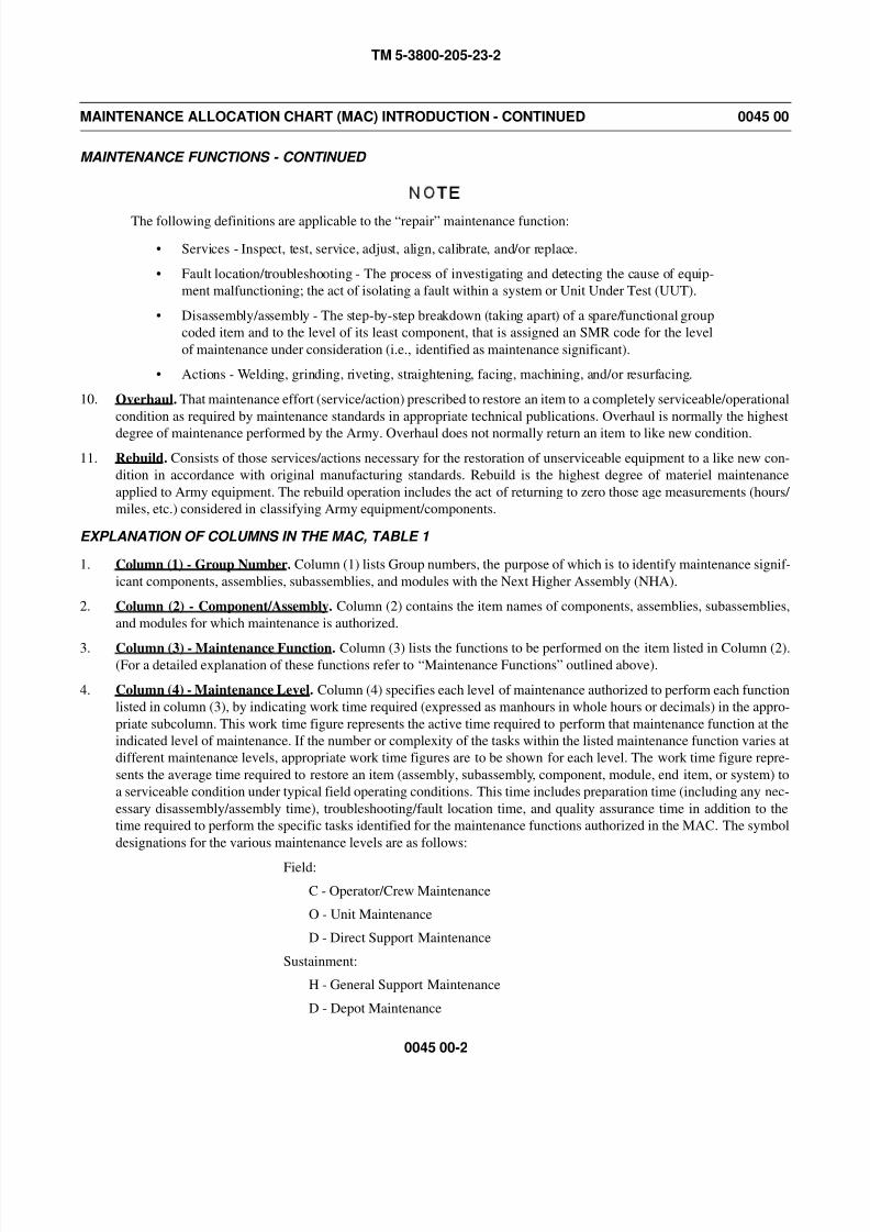
8/14/2019 TM 5-3800-205-23-2 MODEL 613CS
http://slidepdf.com/reader/full/tm-5-3800-205-23-2-model-613cs 208/276
TM 5-3800-205-23-2
0045 00-2
MAINTENANCE ALLOCATION CHART (MAC) INTRODUCTION - CONTINUED 0045 00
MAINTENANCE FUNCTIONS - CONTINUED
NOTE
The following definitions are applicable to the “repair” maintenance function:
• Services - Inspect, test, service, adjust, align, calibrate, and/or replace.
• Fault location/troubleshooting - The process of investigating and detecting the cause of equip-
ment malfunctioning; the act of isolating a fault within a system or Unit Under Test (UUT).
• Disassembly/assembly - The step-by-step breakdown (taking apart) of a spare/functional group
coded item and to the level of its least component, that is assigned an SMR code for the level
of maintenance under consideration (i.e., identified as maintenance significant).
• Actions - Welding, grinding, riveting, straightening, facing, machining, and/or resurfacing.
10. Overhaul. That maintenance effort (service/action) prescribed to restore an item to a completely serviceable/operational
condition as required by maintenance standards in appropriate technical publications. Overhaul is normally the highest
degree of maintenance performed by the Army. Overhaul does not normally return an item to like new condition.
11. Rebuild. Consists of those services/actions necessary for the restoration of unserviceable equipment to a like new con-
dition in accordance with original manufacturing standards. Rebuild is the highest degree of materiel maintenance
applied to Army equipment. The rebuild operation includes the act of returning to zero those age measurements (hours/
miles, etc.) considered in classifying Army equipment/components.
EXPLANATION OF COLUMNS IN THE MAC, TABLE 1
1. Column (1) - Group Number. Column (1) lists Group numbers, the purpose of which is to identify maintenance signif-
icant components, assemblies, subassemblies, and modules with the Next Higher Assembly (NHA).
2. Column (2) - Component/Assembly. Column (2) contains the item names of components, assemblies, subassemblies,
and modules for which maintenance is authorized.
3. Column (3) - Maintenance Function. Column (3) lists the functions to be performed on the item listed in Column (2).(For a detailed explanation of these functions refer to “Maintenance Functions” outlined above).
4. Column (4) - Maintenance Level. Column (4) specifies each level of maintenance authorized to perform each function
listed in column (3), by indicating work time required (expressed as manhours in whole hours or decimals) in the appro-
priate subcolumn. This work time figure represents the active time required to perform that maintenance function at the
indicated level of maintenance. If the number or complexity of the tasks within the listed maintenance function varies at
different maintenance levels, appropriate work time figures are to be shown for each level. The work time figure repre-
sents the average time required to restore an item (assembly, subassembly, component, module, end item, or system) to
a serviceable condition under typical field operating conditions. This time includes preparation time (including any nec-
essary disassembly/assembly time), troubleshooting/fault location time, and quality assurance time in addition to the
time required to perform the specific tasks identified for the maintenance functions authorized in the MAC. The symbol
designations for the various maintenance levels are as follows:
Field:
C - Operator/Crew Maintenance
O - Unit Maintenance
D - Direct Support Maintenance
Sustainment:
H - General Support Maintenance
D - Depot Maintenance

8/14/2019 TM 5-3800-205-23-2 MODEL 613CS
http://slidepdf.com/reader/full/tm-5-3800-205-23-2-model-613cs 209/276
TM 5-3800-205-23-2
0045 00-3
MAINTENANCE ALLOCATION CHART (MAC) INTRODUCTION - CONTINUED 0045 00
EXPLANATION OF COLUMNS IN THE MAC, TABLE 1 - CONTINUED
NOTE
The “L” maintenance level is not included in column (4) of the MAC. Functions to this level of maintenanceare identified by a work time figure in the “H” column of column (4), and an associated reference code is
used in the REMARKS CODE column (6). This code is keyed to the remarks and the SRA complete repair
application is explained there.
5. Column (5) - Tools and Equipment. Column (5) specifies, by code, those common tool sets (not individual tools),
common Test, Measurement and Diagnostic Equipment (TMDE), and special tools, special TMDE, and special support
equipment required to perform the designated function. Codes are keyed to the entries in the Tools and Test Equipment
Requirements, Table 2.
6. Column (6) - Remarks. When applicable, this column contains a letter code, in alphabetical order, which is keyed to
the Remarks, Table 3.
EXPLANATION OF COLUMNS IN THE TOOLS AND TEST EQUIPMENT REQUIREMENTS, TABLE 2
1. Column (1) - Tools or Test Equipment Reference Code. The tool and test equipment reference code correlates with acode used in column (5) of the MAC.
2. Column (2) - Maintenance Level. The lowest level of maintenance authorized to use the tool or test equipment.
3. Column (3) - Nomenclature. Name or identification of the tool or test equipment.
4. Column (4) - National/NATO Stock Number. The NSN of the tool or test equipment.
5. Column (5) - Tool Number. The manufacturer's part number, model number, or type number.
EXPLANATION OF COLUMNS IN THE REMARKS, TABLE 3
1. Column (1) - Reference Code. The code recorded in column (6) of the MAC.
2. Column (2) - Remarks. This column lists information pertinent to the maintenance function being performed as indi-
cated in the MAC.
END OF WORK PACKAGE

8/14/2019 TM 5-3800-205-23-2 MODEL 613CS
http://slidepdf.com/reader/full/tm-5-3800-205-23-2-model-613cs 210/276
TM 5-3800-205-23-2
0045 00-4
This Page Intentionally Left Blank.
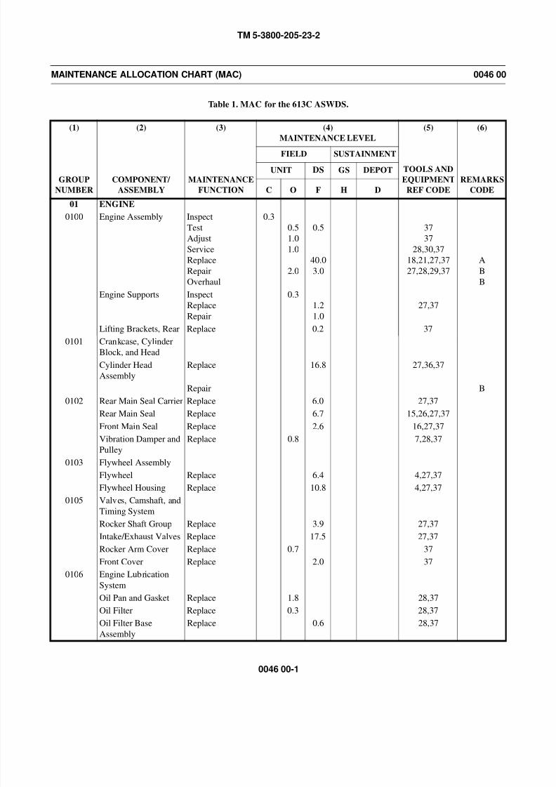
8/14/2019 TM 5-3800-205-23-2 MODEL 613CS
http://slidepdf.com/reader/full/tm-5-3800-205-23-2-model-613cs 211/276
TM 5-3800-205-23-2
0046 00-1
MAINTENANCE ALLOCATION CHART (MAC) 0046 00
Table 1. MAC for the 613C ASWDS.
(1)
GROUP
NUMBER
(2)
COMPONENT/
ASSEMBLY
(3)
MAINTENANCE
FUNCTION
(4)
MAINTENANCE LEVEL
(5)
TOOLS AND
EQUIPMENT
REF CODE
(6)
REMARKS
CODE
FIELD SUSTAINMENT
UNIT DS GS DEPOT
C O F H D
01 ENGINE
0100 Engine Assembly Inspect
Test
Adjust
Service
Replace
RepairOverhaul
0.3
0.5
1.0
1.0
2.0
0.5
40.0
3.0
37
37
28,30,37
18,21,27,37
27,28,29,37
A
BB
Engine Supports Inspect
Replace
Repair
0.3
1.2
1.0
27,37
Lifting Brackets, Rear Replace 0.2 37
0101 Crankcase, Cylinder
Block, and Head
Cylinder Head
Assembly
Replace 16.8 27,36,37
Repair B
0102 Rear Main Seal Carrier Replace 6.0 27,37
Rear Main Seal Replace 6.7 15,26,27,37Front Main Seal Replace 2.6 16,27,37
Vibration Damper and
Pulley
Replace 0.8 7,28,37
0103 Flywheel Assembly
Flywheel Replace 6.4 4,27,37
Flywheel Housing Replace 10.8 4,27,37
0105 Valves, Camshaft, and
Timing System
Rocker Shaft Group Replace 3.9 27,37
Intake/Exhaust Valves Replace 17.5 27,37
Rocker Arm Cover Replace 0.7 37Front Cover Replace 2.0 37
0106 Engine Lubrication
System
Oil Pan and Gasket Replace 1.8 28,37
Oil Filter Replace 0.3 28,37
Oil Filter Base
Assembly
Replace 0.6 28,37
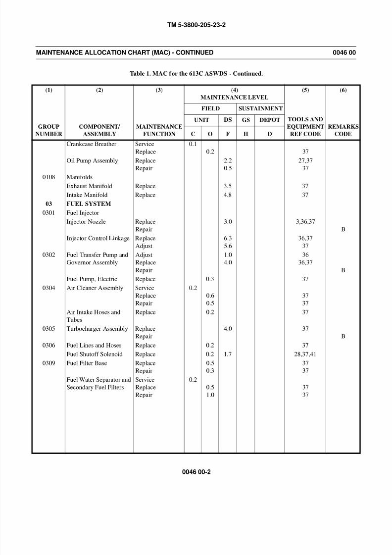
8/14/2019 TM 5-3800-205-23-2 MODEL 613CS
http://slidepdf.com/reader/full/tm-5-3800-205-23-2-model-613cs 212/276
TM 5-3800-205-23-2
0046 00-2
MAINTENANCE ALLOCATION CHART (MAC) - CONTINUED 0046 00
Table 1. MAC for the 613C ASWDS - Continued.
(1)
GROUP
NUMBER
(2)
COMPONENT/
ASSEMBLY
(3)
MAINTENANCE
FUNCTION
(4)
MAINTENANCE LEVEL
(5)
TOOLS AND
EQUIPMENT
REF CODE
(6)
REMARKS
CODE
FIELD SUSTAINMENT
UNIT DS GS DEPOT
C O F H D
Crankcase Breather Service
Replace
0.1
0.2 37
Oil Pump Assembly Replace
Repair
2.2
0.5
27,37
37
0108 Manifolds
Exhaust Manifold Replace 3.5 37
Intake Manifold Replace 4.8 3703 FUEL SYSTEM
0301 Fuel Injector
Injector Nozzle Replace
Repair
3.0 3,36,37
B
Injector Control Linkage Replace
Adjust
6.3
5.6
36,37
37
0302 Fuel Transfer Pump and
Governor Assembly
Adjust
Replace
Repair
1.0
4.0
36
36,37
B
Fuel Pump, Electric Replace 0.3 37
0304 Air Cleaner Assembly Service
Replace
Repair
0.2
0.6
0.5
37
37
Air Intake Hoses and
Tubes
Replace 0.2 37
0305 Turbocharger Assembly Replace
Repair
4.0 37
B
0306 Fuel Lines and Hoses Replace 0.2 37
Fuel Shutoff Solenoid Replace 0.2 1.7 28,37,41
0309 Fuel Filter Base Replace
Repair
0.5
0.3
37
37
Fuel Water Separator and
Secondary Fuel Filters
Service
ReplaceRepair
0.2
0.51.0
3737
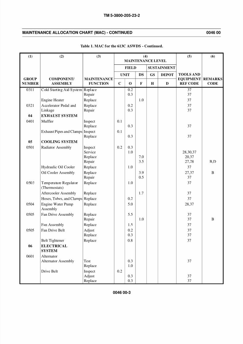
8/14/2019 TM 5-3800-205-23-2 MODEL 613CS
http://slidepdf.com/reader/full/tm-5-3800-205-23-2-model-613cs 213/276
TM 5-3800-205-23-2
0046 00-3
MAINTENANCE ALLOCATION CHART (MAC) - CONTINUED 0046 00
Table 1. MAC for the 613C ASWDS - Continued.
(1)
GROUP
NUMBER
(2)
COMPONENT/
ASSEMBLY
(3)
MAINTENANCE
FUNCTION
(4)
MAINTENANCE LEVEL
(5)
TOOLS AND
EQUIPMENT
REF CODE
(6)
REMARKS
CODE
FIELD SUSTAINMENT
UNIT DS GS DEPOT
C O F H D
0311 Cold Starting Aid System Replace
Repair
0.2
0.3
37
37
Engine Heater Replace 1.0 37
0321 Accelerator Pedal and
Linkage
Replace
Repair
0.2
0.3
37
37
04 EXHAUST SYSTEM
0401 Muffler InspectReplace
0.10.3 37
Exhaust Pipes and Clamps Inspect
Replace
0.1
0.3 37
05 COOLING SYSTEM
0501 Radiator Assembly Inspect
Service
Replace
Repair
0.2 0.3
1.0
7.0
3.5
28,30,37
20,37
27,28 B,D
Hydraulic Oil Cooler Replace 1.0 37
Oil Cooler Assembly Replace
Repair
3.9
0.5
27,37
37
B
0503 Temperature Regulator
(Thermostats)
Replace 1.0 37
Aftercooler Assembly Replace 1.7 37
Hoses, Tubes, and Clamps Replace 0.2 37
0504 Engine Water Pump
Assembly
Replace 5.0 28,37
0505 Fan Drive Assembly Replace
Repair
5.5
1.0
37
37 B
Fan Assembly Replace 1.5 37
0505 Fan Drive Belt Adjust
Replace
0.2
0.3
37
37
Belt Tightener Replace 0.8 3706 ELECTRICAL
SYSTEM
0601 Alternator
Alternator Assembly Test
Replace
0.3
1.0
37
Drive Belt Inspect
Adjust
Replace
0.2
0.3
0.3
37
37
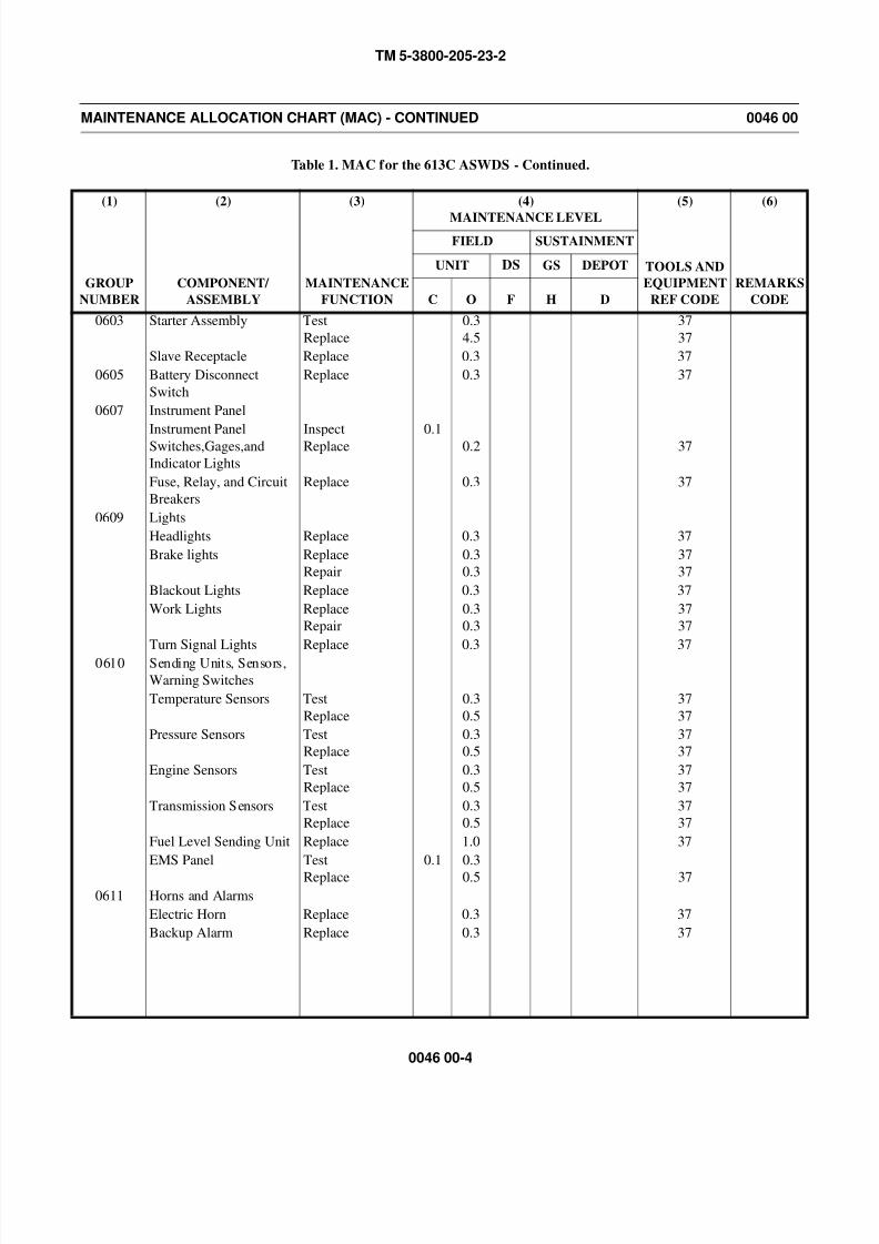
8/14/2019 TM 5-3800-205-23-2 MODEL 613CS
http://slidepdf.com/reader/full/tm-5-3800-205-23-2-model-613cs 214/276
TM 5-3800-205-23-2
0046 00-4
MAINTENANCE ALLOCATION CHART (MAC) - CONTINUED 0046 00
Table 1. MAC for the 613C ASWDS - Continued.
(1)
GROUP
NUMBER
(2)
COMPONENT/
ASSEMBLY
(3)
MAINTENANCE
FUNCTION
(4)
MAINTENANCE LEVEL
(5)
TOOLS AND
EQUIPMENT
REF CODE
(6)
REMARKS
CODE
FIELD SUSTAINMENT
UNIT DS GS DEPOT
C O F H D
0603 Starter Assembly Test
Replace
0.3
4.5
37
37
Slave Receptacle Replace 0.3 37
0605 Battery Disconnect
Switch
Replace 0.3 37
0607 Instrument Panel
Instrument PanelSwitches,Gages,and
Indicator Lights
InspectReplace 0.1 0.2 37
Fuse, Relay, and Circuit
Breakers
Replace 0.3 37
0609 Lights
Headlights Replace 0.3 37
Brake lights Replace
Repair
0.3
0.3
37
37
Blackout Lights Replace 0.3 37
Work Lights Replace
Repair
0.3
0.3
37
37
Turn Signal Lights Replace 0.3 37
0610 Sending Units, Sensors,
Warning Switches
Temperature Sensors Test
Replace
0.3
0.5
37
37
Pressure Sensors Test
Replace
0.3
0.5
37
37
Engine Sensors Test
Replace
0.3
0.5
37
37
Transmission Sensors Test
Replace
0.3
0.5
37
37
Fuel Level Sending Unit Replace 1.0 37
EMS Panel Test
Replace
0.1 0.3
0.5 37
0611 Horns and Alarms
Electric Horn Replace 0.3 37
Backup Alarm Replace 0.3 37
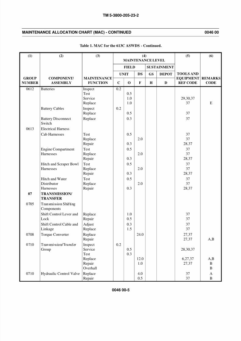
8/14/2019 TM 5-3800-205-23-2 MODEL 613CS
http://slidepdf.com/reader/full/tm-5-3800-205-23-2-model-613cs 215/276
TM 5-3800-205-23-2
0046 00-5
MAINTENANCE ALLOCATION CHART (MAC) - CONTINUED 0046 00
Table 1. MAC for the 613C ASWDS - Continued.
(1)
GROUP
NUMBER
(2)
COMPONENT/
ASSEMBLY
(3)
MAINTENANCE
FUNCTION
(4)
MAINTENANCE LEVEL
(5)
TOOLS AND
EQUIPMENT
REF CODE
(6)
REMARKS
CODE
FIELD SUSTAINMENT
UNIT DS GS DEPOT
C O F H D
0612 Batteries Inspect
Test
Service
Replace
0.2
0.5
1.0
1.0
29,30,37
37 E
Battery Cables Inspect
Replace
0.2
0.5 37
Battery DisconnectSwitch
Replace 0.3 37
0613 Electrical Harness
Cab Harnesses Test
Replace
Repair
0.5
0.3
2.0
37
37
28,37
Engine Compartment
Harnesses
Test
Replace
Repair
0.5
0.3
2.0
37
37
28,37
Hitch and Scraper Bowl
Harnesses
Test
Replace
Repair
0.5
0.3
2.0
37
37
28,37
Hitch and WaterDistributor
Harnesses
TestReplace
Repair
0.5
0.3
2.03737
28,37
07 TRANSMISSION/
TRANSFER
0705 Transmission Shifting
Components
Shift Control Lever and
Lock
Replace
Repair
1.0
0.5
37
37
Shift Control Cable and
Linkage
Adjust
Replace
0.3
1.5
37
37
0708 Torque Converter Replace
Repair
24.0 27,37
27,37 A,B0710 Transmission/Transfer
Group
Inspect
Service
Test
Replace
Repair
Overhall
0.2
0.5
0.3
12.0
1.0
28,30,37
6,27,37
27,37
A,B
B
B
0710 Hydraulic Control Valve Replace
Repair
4.0
0.5
37
37
A
B
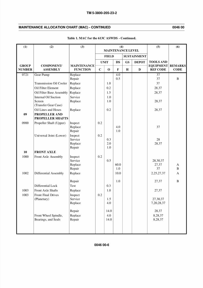
8/14/2019 TM 5-3800-205-23-2 MODEL 613CS
http://slidepdf.com/reader/full/tm-5-3800-205-23-2-model-613cs 216/276
TM 5-3800-205-23-2
0046 00-6
MAINTENANCE ALLOCATION CHART (MAC) - CONTINUED 0046 00
Table 1. MAC for the 613C ASWDS - Continued.
(1)
GROUP
NUMBER
(2)
COMPONENT/
ASSEMBLY
(3)
MAINTENANCE
FUNCTION
(4)
MAINTENANCE LEVEL
(5)
TOOLS AND
EQUIPMENT
REF CODE
(6)
REMARKS
CODE
FIELD SUSTAINMENT
UNIT DS GS DEPOT
C O F H D
0721 Gear Pump Replace
Repair
4.0
0.5
37
37 B
Transmission Oil Cooler Replace 1.0 37
Oil Filter Element Replace 0.2 28,37
Oil Filter Base Assembly Replace 1.5 28,37
Internal Oil Suction
Screen(Transfer Gear Case)
Service
Replace
1.0
1.0 28,37
Oil Lines and Hoses Replace 0.2 28,37
09 PROPELLER AND
PROPELLER SHAFTS
0900 Propeller Shaft (Upper) Inspect
Replace
Repair
0.2
4.0
1.0
37
Universal Joint (Lower) Inspect
Service
Replace
Repair
0.2
0.3
2.0
1.0
28
28,37
10 FRONT AXLE
1000 Front Axle Assembly Inspect
Service
Replace
Repair
0.2
0.5
60.0
1.0
28,30,37
27,37
37
A
B
1002 Differential Assembly Replace
Repair
10.0
1.0
2,25,27,37
27,37
A
B
Differential Lock Test 0.3
1003 Front Axle Shafts Replace 1.0 27,37
1003 Front Final Drives
(Planetary)
Inspect
Service
Replace
Repair
0.2
1.5
4.0
14.0
27,30,37
7,20,28,37
28,37
Front Wheel Spindle,
Bearings, and Seals
Replace
Repair
4.0
14.0
8,28,37
8,28,37
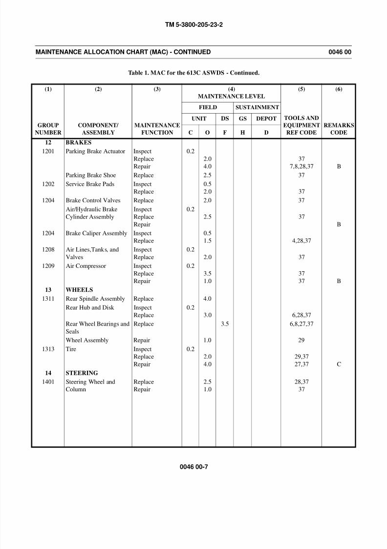
8/14/2019 TM 5-3800-205-23-2 MODEL 613CS
http://slidepdf.com/reader/full/tm-5-3800-205-23-2-model-613cs 217/276
TM 5-3800-205-23-2
0046 00-7
MAINTENANCE ALLOCATION CHART (MAC) - CONTINUED 0046 00
Table 1. MAC for the 613C ASWDS - Continued.
(1)
GROUP
NUMBER
(2)
COMPONENT/
ASSEMBLY
(3)
MAINTENANCE
FUNCTION
(4)
MAINTENANCE LEVEL
(5)
TOOLS AND
EQUIPMENT
REF CODE
(6)
REMARKS
CODE
FIELD SUSTAINMENT
UNIT DS GS DEPOT
C O F H D
12 BRAKES
1201 Parking Brake Actuator Inspect
Replace
Repair
0.2
2.0
4.0
37
7,8,28,37 B
Parking Brake Shoe Replace 2.5 37
1202 Service Brake Pads Inspect
Replace
0.5
2.0 371204 Brake Control Valves Replace 2.0 37
Air/Hydraulic Brake
Cylinder Assembly
Inspect
Replace
Repair
0.2
2.5 37
B
1204 Brake Caliper Assembly Inspect
Replace
0.5
1.5 4,28,37
1208 Air Lines,Tanks, and
Valves
Inspect
Replace
0.2
2.0 37
1209 Air Compressor Inspect
Replace
Repair
0.2
3.5
1.0
37
37 B
13 WHEELS
1311 Rear Spindle Assembly Replace 4.0
Rear Hub and Disk Inspect
Replace
0.2
3.0 6,28,37
Rear Wheel Bearings and
Seals
Replace 3.5 6,8,27,37
Wheel Assembly Repair 1.0 29
1313 Tire Inspect
Replace
Repair
0.2
2.0
4.0
29,37
27,37 C
14 STEERING
1401 Steering Wheel andColumn ReplaceRepair 2.51.0 28,3737
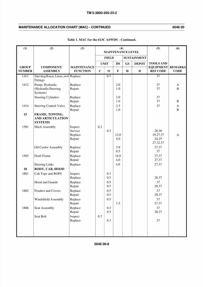
8/14/2019 TM 5-3800-205-23-2 MODEL 613CS
http://slidepdf.com/reader/full/tm-5-3800-205-23-2-model-613cs 218/276
TM 5-3800-205-23-2
0046 00-8
MAINTENANCE ALLOCATION CHART (MAC) - CONTINUED 0046 00
Table 1. MAC for the 613C ASWDS - Continued.
(1)
GROUP
NUMBER
(2)
COMPONENT/
ASSEMBLY
(3)
MAINTENANCE
FUNCTION
(4)
MAINTENANCE LEVEL
(5)
TOOLS AND
EQUIPMENT
REF CODE
(6)
REMARKS
CODE
FIELD SUSTAINMENT
UNIT DS GS DEPOT
C O F H D
1411 Steering Hoses, Lines, and
Fittings
Replace 0.5 37
1412 Pump, Hydraulic
(Hydraulic/Steering
Systems)
Replace
Repair
2.0
1.0
37
37
A
B
Steering Cylinders Replace
Repair
2.0
1.0
37
37 B
1414 Steering Control Valve Replace
Repair
2.5
1.0
37 A
B
15 FRAME, TOWING,
AND ARTICULATION
SYSTEMS
1501 Hitch Assembly Inspect
Service
Replace
Repair
0.2
0.3
12.0
4.0
28,30
19,27,37
24,25
27,32,37
A
Oil Cooler Assembly Replace
Repair
3.9
0.5
27,37
37
1503 Draft Frame Replace
Repair
16.0
4.0
27,37
27,37
Steering Links Replace 4.0 27,37
18 BODY, CAB, HOOD
1801 Cab Tops and ROPS Inspect
Replace
0.3
0.5 28,37
Hood and Guards Replace
Repair
0.5
0.5
37
29,37
1802 Fenders and Covers Replace
Repair
0.5
0.5
37
29,37
Windshield Assembly Replace
Repair
0.5
1.5
37
27,37
1806 Seat Assembly Replace
Repair
0.3
0.5
37
28,37
Seat Belt Inspect
Replace
0.2
0.3 37
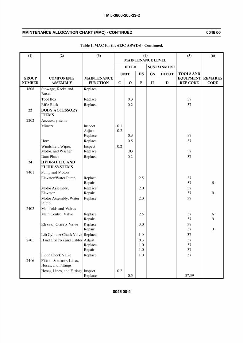
8/14/2019 TM 5-3800-205-23-2 MODEL 613CS
http://slidepdf.com/reader/full/tm-5-3800-205-23-2-model-613cs 219/276
TM 5-3800-205-23-2
0046 00-9
MAINTENANCE ALLOCATION CHART (MAC) - CONTINUED 0046 00
Table 1. MAC for the 613C ASWDS - Continued.
(1)
GROUP
NUMBER
(2)
COMPONENT/
ASSEMBLY
(3)
MAINTENANCE
FUNCTION
(4)
MAINTENANCE LEVEL
(5)
TOOLS AND
EQUIPMENT
REF CODE
(6)
REMARKS
CODE
FIELD SUSTAINMENT
UNIT DS GS DEPOT
C O F H D
1808 Stowage, Racks and
Boxes
Replace
Tool Box Replace 0.3 37
Rifle Rack Replace 0.2 37
22 BODY ACCESSORY
ITEMS
2202 Accessory itemsMirrors Inspect
Adjust
Replace
0.1
0.2
0.3 37
Horn Replace 0.5 37
Windshield Wiper,
Motor, and Washer
Inspect
Replace
0.2
.03 37
Data Plates Replace 0.2 37
24 HYDRAULIC AND
FLUID SYSTEMS
2401 Pump and Motors
Elevator/Water Pump Replace
Repair
2.5 37
37 B
Motor Assembly,
Elevator
Replace
Repair
2.0 37
37 B
Motor Assembly, Water
Pump
Replace 2.0 37
2402 Manifolds and Valves
Main Control Valve Replace
Repair
2.5 37
37
A
B
Elevator Control Valve Replace
Repair
3.0 37
37 B
Lift Cylinder Check Valve Replace 1.0 37
2403 Hand Controls and Cables AdjustReplace
Repair
0.31.0
1.0
3737
37
Floor Check Valve Replace 1.0 37
2406 Filters, Strainers, Lines,
Hoses, and Fittings
Hoses, Lines, and Fittings Inspect
Replace
0.2
0.5 37,39
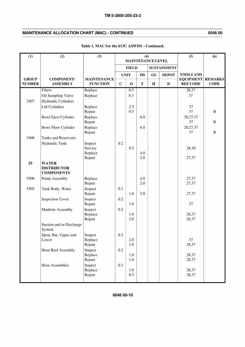
8/14/2019 TM 5-3800-205-23-2 MODEL 613CS
http://slidepdf.com/reader/full/tm-5-3800-205-23-2-model-613cs 220/276
TM 5-3800-205-23-2
0046 00-10
MAINTENANCE ALLOCATION CHART (MAC) - CONTINUED 0046 00
Table 1. MAC for the 613C ASWDS - Continued.
(1)
GROUP
NUMBER
(2)
COMPONENT/
ASSEMBLY
(3)
MAINTENANCE
FUNCTION
(4)
MAINTENANCE LEVEL
(5)
TOOLS AND
EQUIPMENT
REF CODE
(6)
REMARKS
CODE
FIELD SUSTAINMENT
UNIT DS GS DEPOT
C O F H D
Filters Replace 0.5 28,37
Oil Sampling Valve Replace 0.3 37
2407 Hydraulic Cylinders
Lift Cylinders Replace
Repair
2.5
0.5
37
37 B
Bowl Eject Cylinder Replace
Repair
6.0 20,27,37
37 BBowl Floor Cylinder Replace
Repair
6.0 20,27,37
37 B
2408 Tanks and Reservoirs
Hydraulic Tank Inspect
Service
Replace
Repair
0.2
0.5
4.0
2.0
28,30
27,37
55 WATER
DISTRIBUTOR
COMPONENTS
5500 Pump Assembly Replace
Repair
4.0
2.0
27,37
27,37
5505 Tank Body, Water Inspect
Repair
0.3
1.0 2.0 27,37
Inspection Cover Inspect
Repair
0.2
1.0 37
Manhole Assembly Inspect
Replace
Repair
0.2
1.0
2.0
28,37
28,37
Suction and or Discharge
System
Spray Bar, Upper and
Lower
Inspect
Replace
Repair
0.2
2.0
1.0
37
28,37
Hose Reel Assembly Inspect
Replace
Repair
0.2
1.0
1.0
28,37
28,37
Hose Assemblies Inspect
Replace
Repair
0.3
1.0
0.5
28,37
28,37
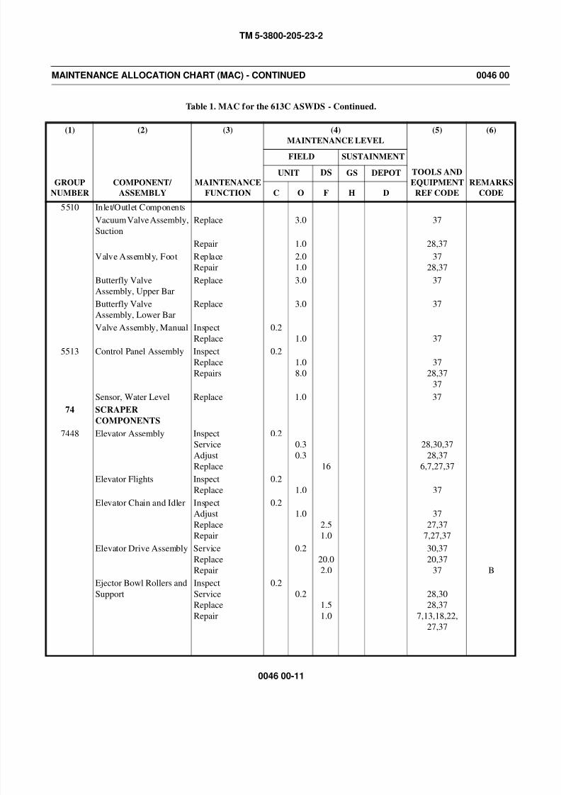
8/14/2019 TM 5-3800-205-23-2 MODEL 613CS
http://slidepdf.com/reader/full/tm-5-3800-205-23-2-model-613cs 221/276
TM 5-3800-205-23-2
0046 00-11
MAINTENANCE ALLOCATION CHART (MAC) - CONTINUED 0046 00
Table 1. MAC for the 613C ASWDS - Continued.
(1)
GROUP
NUMBER
(2)
COMPONENT/
ASSEMBLY
(3)
MAINTENANCE
FUNCTION
(4)
MAINTENANCE LEVEL
(5)
TOOLS AND
EQUIPMENT
REF CODE
(6)
REMARKS
CODE
FIELD SUSTAINMENT
UNIT DS GS DEPOT
C O F H D
5510 Inlet/Outlet Components
Vacuum Valve Assembly,
Suction
Replace 3.0 37
Repair 1.0 28,37
Valve Assembly, Foot Replace
Repair
2.0
1.0
37
28,37
Butterfly ValveAssembly, Upper Bar
Replace 3.0 37
Butterfly Valve
Assembly, Lower Bar
Replace 3.0 37
Valve Assembly, Manual Inspect
Replace
0.2
1.0 37
5513 Control Panel Assembly Inspect
Replace
Repairs
0.2
1.0
8.0
37
28,37
37
Sensor, Water Level Replace 1.0 37
74 SCRAPER
COMPONENTS
7448 Elevator Assembly Inspect
Service
Adjust
Replace
0.2
0.3
0.3
16
28,30,37
28,37
6,7,27,37
Elevator Flights Inspect
Replace
0.2
1.0 37
Elevator Chain and Idler Inspect
Adjust
Replace
Repair
0.2
1.0
2.5
1.0
37
27,37
7,27,37
Elevator Drive Assembly Service
ReplaceRepair
0.2
20.02.0
30,37
20,3737 B
Ejector Bowl Rollers and
Support
Inspect
Service
Replace
Repair
0.2
0.2
1.5
1.0
28,30
28,37
7,13,18,22,
27,37

8/14/2019 TM 5-3800-205-23-2 MODEL 613CS
http://slidepdf.com/reader/full/tm-5-3800-205-23-2-model-613cs 222/276
TM 5-3800-205-23-2
0046 00-12
MAINTENANCE ALLOCATION CHART (MAC) - CONTINUED 0046 00
Table 1. MAC for the 613C ASWDS - Continued.
(1)
GROUP
NUMBER
(2)
COMPONENT/
ASSEMBLY
(3)
MAINTENANCE
FUNCTION
(4)
MAINTENANCE LEVEL
(5)
TOOLS AND
EQUIPMENT
REF CODE
(6)
REMARKS
CODE
FIELD SUSTAINMENT
UNIT DS GS DEPOT
C O F H D
7448 Bowl Sliding Floor Inspect
Replace
Repair
0.2
6.0
2.0
27,37
7,13,22,27,37
Bowl Sliding Floor
Roller, Link and Support
Replace
Bowl Sliding Floor Link,
and Support
Inspect
ReplaceRepair
0.2
6.02.0
27,3727,37

8/14/2019 TM 5-3800-205-23-2 MODEL 613CS
http://slidepdf.com/reader/full/tm-5-3800-205-23-2-model-613cs 223/276
TM 5-3800-205-23-2
0046 00-13
MAINTENANCE ALLOCATION CHART (MAC) - CONTINUED 0046 00
Table 2. Tools and Test Equipment Requirement for the 613C ASWDS.
(1)
Tools or Test
Equipment
Reference
Code
(2)
Maintenance
Level
(3)
Nomenclature
(4)
National/NATO
Stock Number
(5)
Tool
Number
1 F Adapter, Mechanical Puller 5120-01-286-8435 1P1835
2 F Adapter, Mechanical Puller 5120-01-288-2717 5P4184
3 F Bar, Governor 2815-01-123-5891 5P0302
4 O Bolt, Guide 3040-01-517-2921 9U-6896
5 O,F Bearing, Sleeve 5365-01-394-1970 3J9511
6 F Bracket, Link 5340-01-476-1734 138-7574
7 O,F Bushing Driver Set 5120-01-030-1626 1P0510
8 O,F Bushing Driver Set 5120-01-039-4811 1P0520
9 F Clamp, Plier 5120-01-503-5364 136-4149
10 F Cylinder, Assembly 3040-01-264-9538 8S7650
11 F Distorter, Tool Group 5110-01-288-2428 5P7318
12 O Guard, Safety, Tire Inflation 4910-00-025-0623 64E33077
13 F Guide Seal 5330-01-517-3296 1P-0774
14 O Heater, Gun Type, Electric 4940-01-028-7493 EP-SUL
15 F Inserter, Seal 5120-01-362-2027 1U7598
16 F Inserter, Seal 5120-01-362-2026 1U7430
17 O,F Jack, Dolly Type, Hydraulic: 10 ton
capacity
4910-00-289-7233 93660
18 F Leveler, Load: 6000 lb capacity 3940-01-294-0606 6V6146
19 O Link 4940-01-268-2201 1387573
20 O,F Link, Bearing 5120-01-451-1401 1387575
21 F Link, Chain, End 4010-01-268-9869 5P9736
22 F Puller Attachment, Mechanical 5120-01-293-1430 8B-7554
23 O,F Puller Kit, Universal 5180-01-124-1903 IP3075
24 F Puller, Hydraulic 5130-01-296-4277 6V3175
25 O,F Pump, Hydraulic Ram, Hand
Driven
4320-00-374-1403 4C4865
26 F Ring 5120-01-288-2447 9S8537
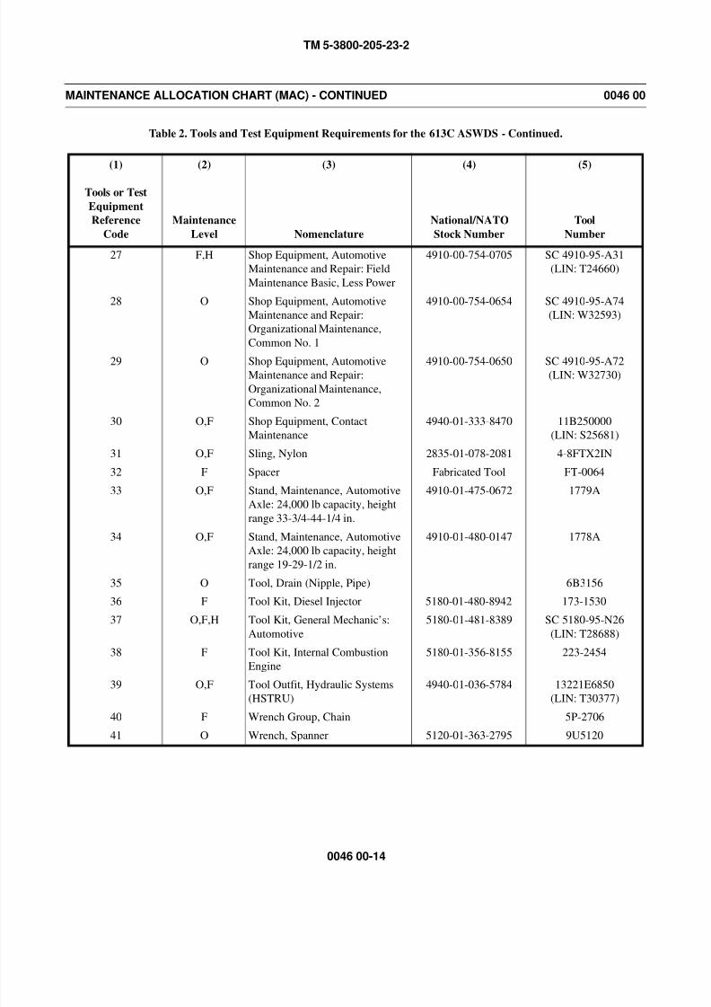
8/14/2019 TM 5-3800-205-23-2 MODEL 613CS
http://slidepdf.com/reader/full/tm-5-3800-205-23-2-model-613cs 224/276
TM 5-3800-205-23-2
0046 00-14
MAINTENANCE ALLOCATION CHART (MAC) - CONTINUED 0046 00
Table 2. Tools and Test Equipment Requirements for the 613C ASWDS - Continued.
(1)
Tools or Test
Equipment
Reference
Code
(2)
Maintenance
Level
(3)
Nomenclature
(4)
National/NATO
Stock Number
(5)
Tool
Number
27 F,H Shop Equipment, Automotive
Maintenance and Repair: Field
Maintenance Basic, Less Power
4910-00-754-0705 SC 4910-95-A31
(LIN: T24660)
28 O Shop Equipment, Automotive
Maintenance and Repair:
Organizational Maintenance,
Common No. 1
4910-00-754-0654 SC 4910-95-A74
(LIN: W32593)
29 O Shop Equipment, Automotive
Maintenance and Repair:
Organizational Maintenance,
Common No. 2
4910-00-754-0650 SC 4910-95-A72
(LIN: W32730)
30 O,F Shop Equipment, Contact
Maintenance
4940-01-333-8470 11B250000
(LIN: S25681)
31 O,F Sling, Nylon 2835-01-078-2081 4-8FTX2IN
32 F Spacer Fabricated Tool FT-0064
33 O,F Stand, Maintenance, Automotive
Axle: 24,000 lb capacity, height
range 33-3/4-44-1/4 in.
4910-01-475-0672 1779A
34 O,F Stand, Maintenance, Automotive
Axle: 24,000 lb capacity, height
range 19-29-1/2 in.
4910-01-480-0147 1778A
35 O Tool, Drain (Nipple, Pipe) 6B3156
36 F Tool Kit, Diesel Injector 5180-01-480-8942 173-1530
37 O,F,H Tool Kit, General Mechanic’s:
Automotive
5180-01-481-8389 SC 5180-95-N26
(LIN: T28688)
38 F Tool Kit, Internal Combustion
Engine
5180-01-356-8155 223-2454
39 O,F Tool Outfit, Hydraulic Systems
(HSTRU)
4940-01-036-5784 13221E6850
(LIN: T30377)
40 F Wrench Group, Chain 5P-2706
41 O Wrench, Spanner 5120-01-363-2795 9U5120
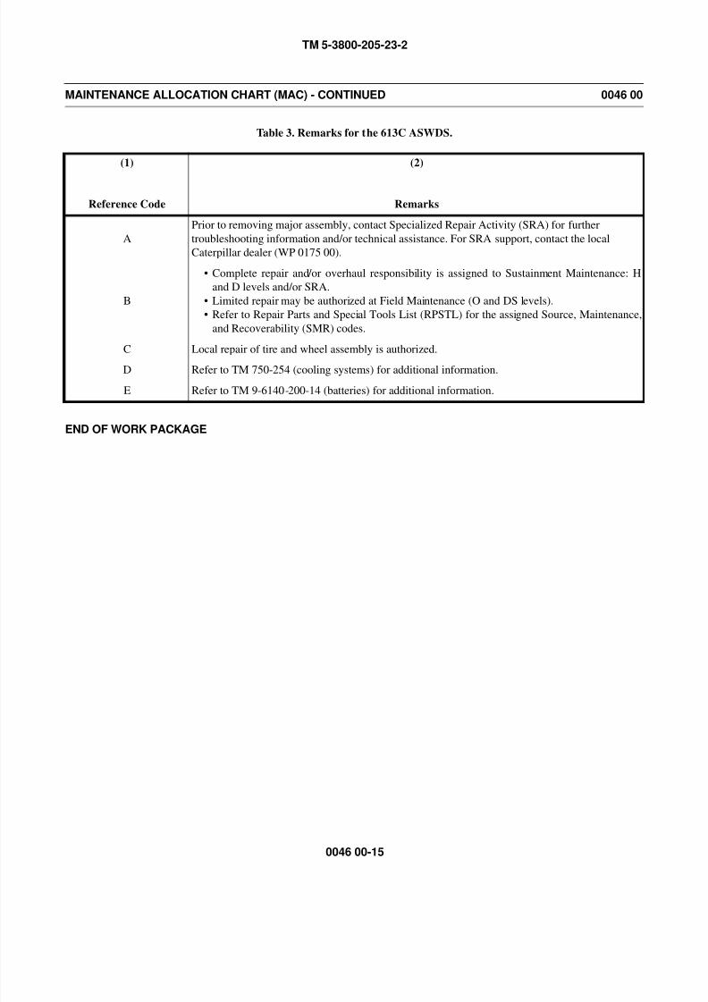
8/14/2019 TM 5-3800-205-23-2 MODEL 613CS
http://slidepdf.com/reader/full/tm-5-3800-205-23-2-model-613cs 225/276
TM 5-3800-205-23-2
0046 00-15
MAINTENANCE ALLOCATION CHART (MAC) - CONTINUED 0046 00
Table 3. Remarks for the 613C ASWDS.
END OF WORK PACKAGE
(1)
Reference Code
(2)
Remarks
A
Prior to removing major assembly, contact Specialized Repair Activity (SRA) for further
troubleshooting information and/or technical assistance. For SRA support, contact the local
Caterpillar dealer (WP 0175 00).
B
• Complete repair and/or overhaul responsibility is assigned to Sustainment Maintenance: H
and D levels and/or SRA.
• Limited repair may be authorized at Field Maintenance (O and DS levels).
• Refer to Repair Parts and Special Tools List (RPSTL) for the assigned Source, Maintenance,
and Recoverability (SMR) codes.
C Local repair of tire and wheel assembly is authorized.
D Refer to TM 750-254 (cooling systems) for additional information.
E Refer to TM 9-6140-200-14 (batteries) for additional information.

8/14/2019 TM 5-3800-205-23-2 MODEL 613CS
http://slidepdf.com/reader/full/tm-5-3800-205-23-2-model-613cs 226/276
TM 5-3800-205-23-2
0046 00-16
This Page Intentionally Left Blank.

8/14/2019 TM 5-3800-205-23-2 MODEL 613CS
http://slidepdf.com/reader/full/tm-5-3800-205-23-2-model-613cs 227/276
TM 5-3800-205-23-2
0047 00-1
EXPENDABLE AND DURABLE ITEMS LIST 0047 00
SCOPE
This work package lists expendable and durable items you will need to maintain the 613CS Scraper and 613CWD Water
Distributor. This listing is for information only and is not authority to requisition the listed items. These items are authorized to
you by CTA 8-100, Army Medical Department Expendable/Durable Items.
EXPLANATION OF COLUMNS
1. Column (1) - Item Number. This number is assigned to the entry in the list and is referenced in the narrative instruc-
tions to identify the item [e.g., Use antifreeze (Item 3, WP 0047 00)].
2. Column (2) - Level. This column identifies the lowest level of maintenance that requires the listed item.
C - Operator/Crew
O - Organizational Maintenance
3. Column (3) - National Stock Number (NSN). This is the NSN assigned to the item which you can use to requisition it.
4. Column (4) - Description, Item Name, Commercial and Government Entity Code (CAGEC), and Part Number
(P/N). This provides the other information you need to identify the item.
5. Column (5) - Unit of Measure (U/M). This code shows the physical measurement or count of an item, such as gallon,dozen, gross, etc.
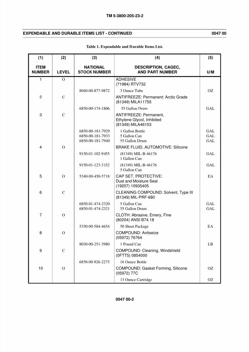
8/14/2019 TM 5-3800-205-23-2 MODEL 613CS
http://slidepdf.com/reader/full/tm-5-3800-205-23-2-model-613cs 228/276
TM 5-3800-205-23-2
0047 00-2
EXPENDABLE AND DURABLE ITEMS LIST - CONTINUED 0047 00
Table 1. Expendable and Durable Items List.
(1)
ITEM
NUMBER
(2)
LEVEL
(3)
NATIONAL
STOCK NUMBER
(4)
DESCRIPTION, CAGEC,
AND PART NUMBER
(5)
U/M
1 O ADHESIVE(71984) RTV732
8040-00-877-9872 3 Ounce Tube OZ
2 C ANTIFREEZE: Permanent: Arctic Grade(81349) MILA11755
6850-00-174-1806 55 Gallon Drum GAL
3 C ANTIFREEZE: Permanent,
Ethylene Glycol, Inhibited
(81349) MILA46153
6850-00-181-7929
6850-00-181-7933
6850-00-181-7940
1 Gallon Bottle
5 Gallon Can
55 Gallon Drum
GAL
GAL
GAL
4 O BRAKE FLUID, AUTOMOTIVE: Silicone
9150-01-102-9455 (81349) MIL-B-46176
1 Gallon Can
GAL
9150-01-123-3152 (81349) MIL-B-46176
5 Gallon Can
GAL
5 O 5340-00-450-5718 CAP SET, PROTECTIVE:
Dust and Moisture Seal
(19207) 10935405
EA
6 C CLEANING COMPOUND: Solvent, Type III
(81349) MIL-PRF-680
6850-01-474-2320
6850-01-474-2321
5 Gallon Can
55 Gallon Drum
GAL
GAL
7 O CLOTH: Abrasive, Emery, Fine(80204) ANSI B74.18
5350-00-584-4654 50 Sheet Package EA
8 O COMPOUND: Antiseize(05972) 76764
8030-00-251-3980 1 Pound Can LB
9 C COMPOUND: Cleaning, Windshield
(0FTT5) 0854000
6850-00-926-2275 16 Ounce Bottle
10 O COMPOUND: Gasket Forming, Silicone
(05972) 77C
OZ
13 Ounce Cartridge OZ

8/14/2019 TM 5-3800-205-23-2 MODEL 613CS
http://slidepdf.com/reader/full/tm-5-3800-205-23-2-model-613cs 229/276
TM 5-3800-205-23-2
0047 00-3
EXPENDABLE AND DURABLE ITEMS LIST - CONTINUED 0047 00
Table 1. Expendable and Durable Items List - Continued.
(1)
ITEM
NUMBER
(2)
LEVEL
(3)
NATIONAL
STOCK NUMBER
(4)
DESCRIPTION, CAGEC,
AND PART NUMBER
(5)
U/M
11 C DETERGENT: General Purpose, Liquid
(83421) 7930-00-282-9699
7930-00-282-9699 1 Gallon Can GAL
12 O FLUX: Soldering
(58536) A-A-51145TY1 FORM A
3439-00-255-9935 1 Pound Can LB
13 C FUEL: Diesel, DF-1 Grade, Winter(81346) ASTM D 975
9140-00-286-5286
9140-00-286-5287
9140-00-286-5288
Bulk
5 Gallon Can
55 Gallon Drum
GAL
GAL
GAL
14 C FUEL: Diesel, DF-2 Grade
(81346) ASTM D 975
9140-00-286-5294
9140-00-286-5295
9140-00-286-5296
Bulk
5 Gallon Can
55 Gallon Drum
GAL
GAL
GAL
15 C 9130-01-031-5816 FUEL, TURBINE: Aviation
(81349) MILT83133 GR JP8
GAL
16 C GREASE: Automotive and Artillery, GAA
9150-01-197-7688 (81349) M-10924-A2-1/4 Ounce Tube
OZ
9150-01-197-7690 (81349) M-10924-C
1-3/4 Pound Can
LB
9150-01-197-7692 (81349) M-10924-E
35 Pound Can
LB
9150-01-197-7693 (81349) M-10924-B
14 Ounce Cartridge
OZ
17 O 9150-01-361-8919 GREASE: Electrically Conductive(53711) 5190179
OZ
18 HOSE: Clear, Neoprene
19 O INSULATING VARNISH: Electrical, Dielectric(75037) 1602
5970-00-476-6717 13 Ounce Can, Aerosol Spray OZ
20 O INSULATING SLEEVING: Electrical
(81343) M23053/5-106-0
5970-00-815-1295 250 Foot Spool FT
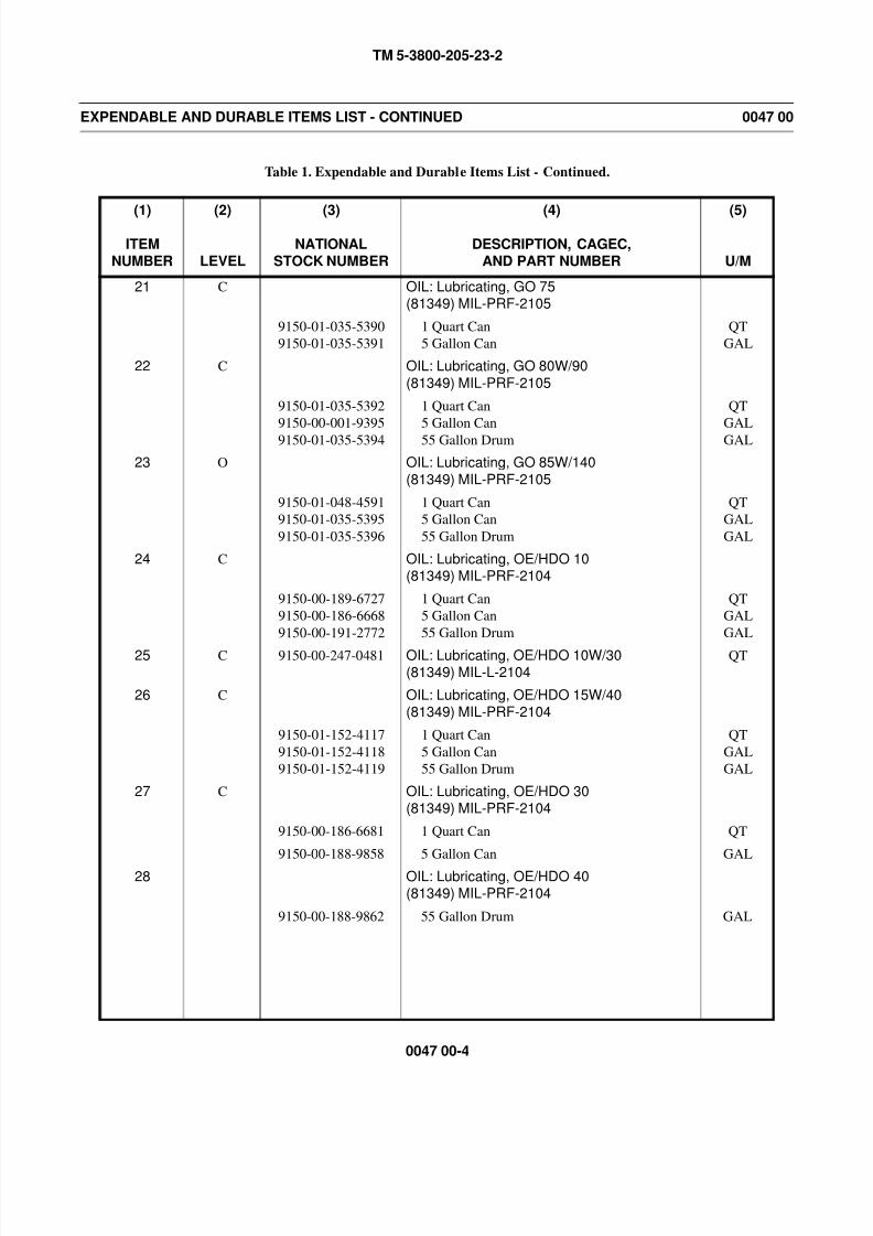
8/14/2019 TM 5-3800-205-23-2 MODEL 613CS
http://slidepdf.com/reader/full/tm-5-3800-205-23-2-model-613cs 230/276
TM 5-3800-205-23-2
0047 00-4
EXPENDABLE AND DURABLE ITEMS LIST - CONTINUED 0047 00
Table 1. Expendable and Durable Items List - Continued.
(1)
ITEM
NUMBER
(2)
LEVEL
(3)
NATIONAL
STOCK NUMBER
(4)
DESCRIPTION, CAGEC,
AND PART NUMBER
(5)
U/M
21 C OIL: Lubricating, GO 75(81349) MIL-PRF-2105
9150-01-035-5390
9150-01-035-5391
1 Quart Can
5 Gallon Can
QT
GAL
22 C OIL: Lubricating, GO 80W/90
(81349) MIL-PRF-2105
9150-01-035-5392
9150-00-001-9395
9150-01-035-5394
1 Quart Can
5 Gallon Can
55 Gallon Drum
QT
GAL
GAL
23 O OIL: Lubricating, GO 85W/140
(81349) MIL-PRF-2105
9150-01-048-4591
9150-01-035-5395
9150-01-035-5396
1 Quart Can
5 Gallon Can
55 Gallon Drum
QT
GAL
GAL
24 C OIL: Lubricating, OE/HDO 10(81349) MIL-PRF-2104
9150-00-189-6727
9150-00-186-6668
9150-00-191-2772
1 Quart Can
5 Gallon Can
55 Gallon Drum
QT
GAL
GAL
25 C 9150-00-247-0481 OIL: Lubricating, OE/HDO 10W/30(81349) MIL-L-2104
QT
26 C OIL: Lubricating, OE/HDO 15W/40(81349) MIL-PRF-2104
9150-01-152-4117
9150-01-152-4118
9150-01-152-4119
1 Quart Can
5 Gallon Can
55 Gallon Drum
QT
GAL
GAL
27 C OIL: Lubricating, OE/HDO 30(81349) MIL-PRF-2104
9150-00-186-6681 1 Quart Can QT
9150-00-188-9858 5 Gallon Can GAL
28 OIL: Lubricating, OE/HDO 40(81349) MIL-PRF-2104
9150-00-188-9862 55 Gallon Drum GAL
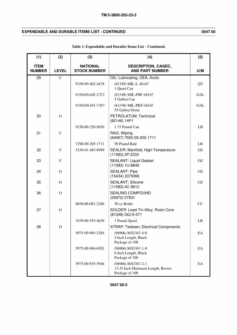
8/14/2019 TM 5-3800-205-23-2 MODEL 613CS
http://slidepdf.com/reader/full/tm-5-3800-205-23-2-model-613cs 231/276
TM 5-3800-205-23-2
0047 00-5
EXPENDABLE AND DURABLE ITEMS LIST - CONTINUED 0047 00
Table 1. Expendable and Durable Items List - Continued.
(1)
ITEM
NUMBER
(2)
LEVEL
(3)
NATIONAL
STOCK NUMBER
(4)
DESCRIPTION, CAGEC,
AND PART NUMBER
(5)
U/M
29 C OIL: Lubricating, OEA, Arctic
9150-00-402-4478 (81349) MIL-L-46167
1 Quart Can
QT
9150-00-402-2372 (81349) MIL-PRF-46167
5 Gallon Can
GAL
9150-00-491-7197 (81349) MIL-PRF-46167
55 Gallon Drum
GAL
30 O PETROLATUM: Technical(82146) 14P1
9150-00-250-0926 1.75 Pound Can LB
31 C RAG: Wiping(64067) 7920-00-205-1711
7290-00-205-1711 50 Pound Bale LB
32 F 5330-01-485-8999 SEALER: Manifold, High-Temperature(11083) 2P-2333
OZ
33 F SEALANT: Liquid Gasket
(11083) 1U-8846
OZ
34 O SEALANT: Pipe
(15434) 3375066
OZ
35 O SEALANT: Silicone(11083) 4C-9612
OZ
36 O SEALING COMPOUND
(05972) 07931
8030-00-081-2286 50 cc Bottle CC
37 O SOLDER: Lead-Tin Alloy, Rosin Core
(81348) QQ-S-571
3439-00-555-4629 1 Pound Spool LB
38 O STRAP: Tiedown, Electrical Components
5975-00-903-2284 (96906) MS3367-4-04 Inch Length, Black
Package of 100
EA
5975-00-984-6582 (96906) MS3367-1-0
6 Inch Length, Black
Package of 100
EA
5975-00-935-5946 (96906) MS3367-2-1
13.35 Inch Minimum Length, Brown
Package of 100
EA
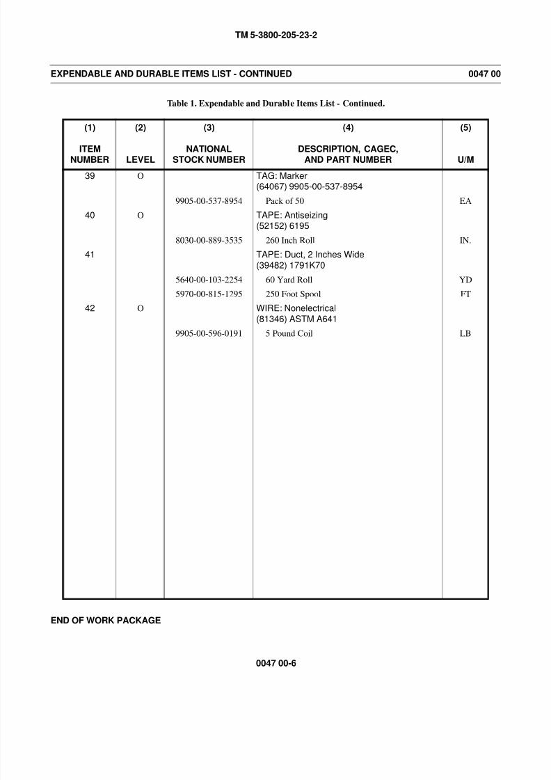
8/14/2019 TM 5-3800-205-23-2 MODEL 613CS
http://slidepdf.com/reader/full/tm-5-3800-205-23-2-model-613cs 232/276
TM 5-3800-205-23-2
0047 00-6
EXPENDABLE AND DURABLE ITEMS LIST - CONTINUED 0047 00
Table 1. Expendable and Durable Items List - Continued.
END OF WORK PACKAGE
(1)
ITEM
NUMBER
(2)
LEVEL
(3)
NATIONAL
STOCK NUMBER
(4)
DESCRIPTION, CAGEC,
AND PART NUMBER
(5)
U/M
39 O TAG: Marker(64067) 9905-00-537-8954
9905-00-537-8954 Pack of 50 EA
40 O TAPE: Antiseizing(52152) 6195
8030-00-889-3535 260 Inch Roll IN.
41 TAPE: Duct, 2 Inches Wide
(39482) 1791K70
5640-00-103-2254 60 Yard Roll YD
5970-00-815-1295 250 Foot Spool FT
42 O WIRE: Nonelectrical
(81346) ASTM A641
9905-00-596-0191 5 Pound Coil LB
8/14/2019 TM 5-3800-205-23-2 MODEL 613CS
http://slidepdf.com/reader/full/tm-5-3800-205-23-2-model-613cs 233/276
TM 5-3800-205-23-2
0048 00-1
TOOL IDENTIFICATION LIST 0048 00
SCOPE
This work package lists all common tools and supplements and special tools/fixtures needed to maintain the 613CS
Scraper and 613CWD Water Distributor.
EXPLANATION OF COLUMNS IN THE TOOL IDENTIFICATION LIST
1. Column (1) - Item Number (No.). This number is assigned to the entry in the list and is referenced in the initial setup to
identify the item (e.g., Tool kit, general mechanic’s, Item 33, WP 0048 00).
2. Column (2) - Item Name. This column lists the item by noun nomenclature and other descriptive features (e.g., Guide,
seal).
3. Column (3) - National Stock Number. This is the National Stock Number (NSN) assigned to the item; use it to requisi-
tion the item.
4. Column (4) - Part Number/CAGEC. Indicates the primary number used by the manufacturer (individual, company,
firm, corporation, or Government activity) which controls the design and characteristics of the item by means of its
engineering drawings, specifications, standards, and inspection requirements to identify an item or range of items. The
manufacturer’s Commercial and Government Entity Code (CAGEC) is also included.
5. Column (5) - Reference. This column identifies the authorizing supply catalog or RPSTL for items listed in this work
package.
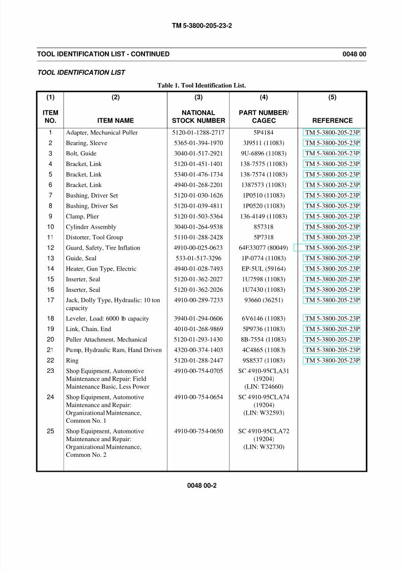
8/14/2019 TM 5-3800-205-23-2 MODEL 613CS
http://slidepdf.com/reader/full/tm-5-3800-205-23-2-model-613cs 234/276
TM 5-3800-205-23-2
0048 00-2
TOOL IDENTIFICATION LIST - CONTINUED 0048 00
TOOL IDENTIFICATION LIST
Table 1. Tool Identification List.
(1)
ITEM
NO.
(2)
ITEM NAME
(3)
NATIONAL
STOCK NUMBER
(4)
PART NUMBER/
CAGEC
(5)
REFERENCE
1 Adapter, Mechanical Puller 5120-01-1288-2717 5P4184 TM 5-3800-205-23P
2 Bearing, Sleeve 5365-01-394-1970 3J9511 (11083) TM 5-3800-205-23P
3 Bolt, Guide 3040-01-517-2921 9U-6896 (11083) TM 5-3800-205-23P
4 Bracket, Link 5120-01-451-1401 138-7575 (11083) TM 5-3800-205-23P
5 Bracket, Link 5340-01-476-1734 138-7574 (11083) TM 5-3800-205-23P
6 Bracket, Link 4940-01-268-2201 1387573 (11083) TM 5-3800-205-23P
7 Bushing, Driver Set 5120-01-030-1626 1P0510 (11083) TM 5-3800-205-23P
8 Bushing, Driver Set 5120-01-039-4811 1P0520 (11083) TM 5-3800-205-23P
9 Clamp, Plier 5120-01-503-5364 136-4149 (11083) TM 5-3800-205-23P
10 Cylinder Assembly 3040-01-264-9538 857318 TM 5-3800-205-23P
11 Distorter, Tool Group 5110-01-288-2428 5P7318 TM 5-3800-205-23P
12 Guard, Safety, Tire Inflation 4910-00-025-0623 64E33077 (80049) TM 5-3800-205-23P
13 Guide, Seal 533-01-517-3296 1P-0774 (11083) TM 5-3800-205-23P
14 Heater, Gun Type, Electric 4940-01-028-7493 EP-5UL (59164) TM 5-3800-205-23P
15 Inserter, Seal 5120-01-362-2027 1U7598 (11083) TM 5-3800-205-23P
16 Inserter, Seal 5120-01-362-2026 1U7430 (11083) TM 5-3800-205-23P
17 Jack, Dolly Type, Hydraulic: 10 toncapacity
4910-00-289-7233 93660 (36251) TM 5-3800-205-23P
18 Leveler, Load: 6000 lb capacity 3940-01-294-0606 6V6146 (11083) TM 5-3800-205-23P
19 Link, Chain, End 4010-01-268-9869 5P9736 (11083) TM 5-3800-205-23P
20 Puller Attachment, Mechanical 5120-01-293-1430 8B-7554 (11083) TM 5-3800-205-23P
21 Pump, Hydraulic Ram, Hand Driven 4320-00-374-1403 4C4865 (11083) TM 5-3800-205-23P
22 Ring 5120-01-288-2447 9S8537 (11083) TM 5-3800-205-23P
23 Shop Equipment, Automotive
Maintenance and Repair: Field
Maintenance Basic, Less Power
4910-00-754-0705 SC 4910-95CLA31
(19204)
(LIN: T24660)
24Shop Equipment, AutomotiveMaintenance and Repair:
Organizational Maintenance,
Common No. 1
4910-00-754-0654 SC 4910-95CLA74(19204)
(LIN: W32593)
25 Shop Equipment, Automotive
Maintenance and Repair:
Organizational Maintenance,
Common No. 2
4910-00-754-0650 SC 4910-95CLA72
(19204)
(LIN: W32730)
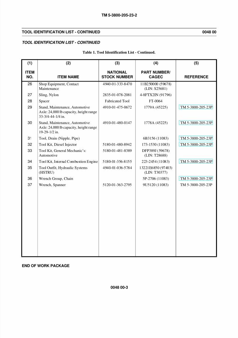
8/14/2019 TM 5-3800-205-23-2 MODEL 613CS
http://slidepdf.com/reader/full/tm-5-3800-205-23-2-model-613cs 235/276
TM 5-3800-205-23-2
0048 00-3
TOOL IDENTIFICATION LIST - CONTINUED 0048 00
TOOL IDENTIFICATION LIST - CONTINUED
Table 1. Tool Identification List - Continued.
END OF WORK PACKAGE
(1)
ITEM
NO.
(2)
ITEM NAME
(3)
NATIONAL
STOCK NUMBER
(4)
PART NUMBER/
CAGEC
(5)
REFERENCE
26 Shop Equipment, Contact
Maintenance
4940-01-333-8470 11B250000 (59678)
(LIN: S25681)
27 Sling, Nylon 2835-01-078-2081 4-8FTX2IN (91796)
28 Spacer Fabricated Tool FT-0064
29 Stand, Maintenance, Automotive
Axle: 24,000 lb capacity, height range
33-3/4-44-1/4 in.
4910-01-475-0672 1779A (45225) TM 5-3800-205-23P
30 Stand, Maintenance, Automotive
Axle: 24,000 lb capacity, height range
19-29-1/2 in.
4910-01-480-0147 1778A (45225) TM 5-3800-205-23P
31 Tool, Drain (Nipple, Pipe) 6B3156 (11083) TM 5-3800-205-23P
32 Tool Kit, Diesel Injector 5180-01-480-8942 173-1530 (11083) TM 5-3800-205-23P
33 Tool Kit, General Mechanic’s:
Automotive
5180-01-481-8389 DFP389J (59678)
(LIN: T28688)
34 Tool Kit, Internal Combustion Engine 5180-01-356-8155 223-2454 (11083) TM 5-3800-205-23P
35 Tool Outfit, Hydraulic Systems
(HSTRU)
4940-01-036-5784 13221E6850 (97403)
(LIN: T30377)
36 Wrench Group, Chain 5P-2706 (11083) TM 5-3800-205-23P
37 Wrench, Spanner 5120-01-363-2795 9U5120 (11083) TM 5-3800-205-23P

8/14/2019 TM 5-3800-205-23-2 MODEL 613CS
http://slidepdf.com/reader/full/tm-5-3800-205-23-2-model-613cs 236/276
TM 5-3800-205-23-2
0048 00-4
This Page Intentionally Left Blank.
8/14/2019 TM 5-3800-205-23-2 MODEL 613CS
http://slidepdf.com/reader/full/tm-5-3800-205-23-2-model-613cs 237/276
TM 5-3800-205-23-2
0049 00-1
TORQUE LIMITS 0049 00
SCOPE
1. This work package lists standard torque values, as shown in Table 1, and provides general information for applying
torque.
2. Special torque values and tightening sequences are indicated in the maintenance procedures for applicable components.
GENERAL
1. Always use the torque values listed in Table 1 when the maintenance procedure does not give a specific torque value.
2. Unless otherwise indicated, standard torque tolerance shall be ±10%.
3. Torque values listed are based on clean, dry threads. Reduce torque by 10% when engine oil is used as a lubricant.
Reduce torque by 20% if new plated capscrews are used.
4. Capscrews threaded into aluminum may require reductions in torque of 30% or more of Grade 5 capscrew torque. Cap-
screw threaded into aluminum must also attain two capscrew diameters of thread engagement.
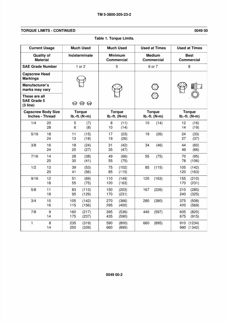
8/14/2019 TM 5-3800-205-23-2 MODEL 613CS
http://slidepdf.com/reader/full/tm-5-3800-205-23-2-model-613cs 238/276
TM 5-3800-205-23-2
0049 00-2
TORQUE LIMITS - CONTINUED 0049 00
Table 1. Torque Limits.
Current Usage Much Used Much Used Used at Times Used at Times
Quality ofMaterial
Indeterminate MinimumCommercial
MediumCommercial
BestCommercial
SAE Grade Number 1 or 2 5 6 or 7 8
Capscrew HeadMarkings
Manufacturer’smarks may vary
These are allSAE Grade 5
(3 line)
Capscrew Body SizeInches - Thread Torquelb.-ft. (N•m) Torquelb.-ft. (N•m) Torquelb.-ft. (N•m) Torquelb.-ft. (N•m)
1/4 20
28
5 (7)
6 (8)
8 (11)
10 (14)
10 (14) 12 (16)
14 (19)
5/16 18
24
11 (15)
13 (18)
17 (23)
19 (26)
19 (26) 24 (33)
27 (37)
3/8 16
24
18 (24)
20 (27)
31 (42)
35 (47)
34 (46) 44 (60)
49 (66)
7/16 14
20
28 (38)
30 (41)
49 (66)
55 (75)
55 (75) 70 (95)
78 (106)
1/2 13
20
39 (53)
41 (56)
75 (102)
85 (115)
85 (115) 105 (142)
120 (163)
9/16 12
18
51 (69)
55 (75)
110 (149)
120 (163)
120 (163) 155 (210)
170 (231)
5/8 1118
83 (113)95 (129)
150 (203)170 (231)
167 (226) 210 (285)240 (325)
3/4 1016
105 (142)115 (156)
270 (366)295 (400)
280 (380) 375 (508)420 (569)
7/8 914
160 (217)175 (237)
395 (536)435 (590)
440 (597) 605 (820)675 (915)
1 8
14
235 (319)
250 (339)
590 (800)
660 (895)
660 (895) 910 (1234)
990 (1342)
8/14/2019 TM 5-3800-205-23-2 MODEL 613CS
http://slidepdf.com/reader/full/tm-5-3800-205-23-2-model-613cs 239/276
TM 5-3800-205-23-2
0050 00-1
PREPARATION FOR STORAGE OR SHIPMENT 0050 00
THIS WORK PACKAGE COVERS:
Preparation for Short-Term Storage
Preparation for Return to Service from Short-Term Storage
Preparation for Long-Term Storage
Preparation for Return to Service from Long-Term Storage
NOTE
Short-term storage is storage for two weeks or less. Long-term storage is for more than two weeks.
PREPARATION FOR SHORT-TERM STORAGE
1. Thoroughly clean machine.
2. Perform Operator Preventive Maintenance Checks and Services (PMCS) (TM 5-3800-205-10-1).
3. Fill fuel tank completely to prevent condensation from forming (TM 5-3800-205-10-1).
4. Perform Unit PMCS (TM 5-3800-205-23-1, WP 0009 00 and WP 0010 00).
5. Schedule next PMCS on ULLS-G (Unit Level Logistics System – Ground).
6. Store machine indoors in a dry, protected area with scraper bowl lowered to the ground (TM 5-3800-205-10-1).
7. When moderate temperatures are expected, leave batteries in place. If extreme cold is expected, remove batteries (TM 5-
3800-205-23-1, WP 0067 00) and store in a protected area.
8. Check engine coolant to ensure coolant has correct mixture for expected temperatures (TB 750-651).
9. Seal all openings in engine, including air intake, exhaust outlet, and crankcase breather tube.
10. Ensure battery disconnect switch is in OFF position (TM 5-3800-205-10-1).
11. Fill in Form DD 1397 completely and attach to a conspicuous part of machine.
PREPARATION FOR RETURN TO SERVICE FROM SHORT-TERM STORAGE
1. Remove seals from all engine openings, including air intake, exhaust outlet, and crankcase breather tube.
2. If removed, install batteries (TM 5-3800-205-23-1, WP 0067 00).
3. Check oil and hydraulic fluid levels in engine crankcase, transmission, front axle differential and wheel end final drives,
and hydraulic tank (PMCS in TM 5-3800-205-10-1 and Unit PMCS in TM 5-3800-205-23-1).
4. Check coolant level in radiator (TM 5-3800-205-10-1).
5. Start engine and perform machine warmup (TM 5-3800-205-10-1). Verify proper operation of all gages, switches, and
EMS indicator and warning lights.
6. Ensure fuel tank is full (TM 5-3800-205-10-1).
7. Operate machine without a load and check engine, transmission, brakes, steering, and electrical accessories for proper
operation (TM 5-3800-205-10-1).
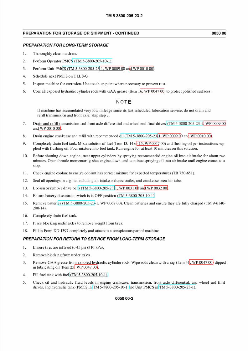
8/14/2019 TM 5-3800-205-23-2 MODEL 613CS
http://slidepdf.com/reader/full/tm-5-3800-205-23-2-model-613cs 240/276
TM 5-3800-205-23-2
0050 00-2
PREPARATION FOR STORAGE OR SHIPMENT - CONTINUED 0050 00
PREPARATION FOR LONG-TERM STORAGE
1. Thoroughly clean machine.
2. Perform Operator PMCS (TM 5-3800-205-10-1).
3. Perform Unit PMCS (TM 5-3800-205-23-1, WP 0009 00 and WP 0010 00).
4. Schedule next PMCS on ULLS-G.
5. Inspect machine for corrosion. Use touch-up paint where necessary to prevent rust.
6. Coat all exposed hydraulic cylinder rods with GAA grease (Item 16, WP 0047 00) to protect polished surfaces.
NOTE
If machine has accumulated very low mileage since its last scheduled lubrication service, do not drain and
refill transmission and front axle; skip step 7.
7. Drain and refill transmission and front axle differential and wheel end final drives (TM 5-3800-205-23-1, WP 0009 00and WP 0010 00).
8. Drain engine crankcase and refill with recommended oil (TM 5-3800-205-23-1, WP 0009 00 and WP 0010 00).
9. Completely drain fuel tank. Mix a solution of fuel (Item 13, 14 or 15, WP 0047 00) and flushing oil per instructions sup-
plied with flushing oil. Pour mixture into fuel tank. Run engine for at least 10 minutes on this solution.
10. Before shutting down engine, treat upper cylinders by spraying recommended engine oil into air intake for about two
minutes. Open throttle momentarily, shut engine down, and continue spraying oil into air intake until engine comes to a
stop.
11. Check engine coolant to ensure coolant has correct mixture for expected temperatures (TB 750-651).
12. Seal all openings in engine, including air intake, exhaust outlet, and crankcase breather tube.
13. Loosen or remove drive belts (TM 5-3800-205-23-1, WP 0031 00 and WP 0032 00).
14. Ensure battery disconnect switch is in OFF position (TM 5-3800-205-10-1).
15. Remove batteries (TM 5-3800-205-23-1, WP 0067 00). Clean batteries and ensure they are fully charged (TM 9-6140-
200-14).
16. Completely drain fuel tank.
17. Place blocking under axles to remove weight from tires.
18. Fill in Form DD 1397 completely and attach to a conspicuous part of machine.
PREPARATION FOR RETURN TO SERVICE FROM LONG-TERM STORAGE
1. Ensure tires are inflated to 45 psi (310 kPa).
2. Remove blocking from under axles.
3. Remove GAA grease from exposed hydraulic cylinder rods. Wipe rods clean with a rag (Item 31, WP 0047 00) dipped
in lubricating oil (Item 25, WP 0047 00).
4. Fill fuel tank with fuel (TM 5-3800-205-10-1).
5. Check oil and hydraulic fluid levels in engine crankcase, transmission, front axle differential, and wheel end final
drives, and hydraulic tank (PMCS in TM 5-3800-205-10-1 and Unit PMCS in TM 5-3800-205-23-1).

8/14/2019 TM 5-3800-205-23-2 MODEL 613CS
http://slidepdf.com/reader/full/tm-5-3800-205-23-2-model-613cs 241/276
TM 5-3800-205-23-2
0050 00-3
PREPARATION FOR STORAGE OR SHIPMENT - CONTINUED 0050 00
PREPARATION FOR RETURN TO SERVICE FROM LONG-TERM STORAGE - CONTINUED
6. Check coolant level in radiator (TM 5-3800-205-10-1).
7. Install fully charged batteries (TM 5-3800-205-23-1, WP 0067 00).
8. Tighten or install drive belts (TM 5-3800-205-23-1, WP 0031 00 and WP 0032 00).
9. Remove seals from all engine openings, including air intake, exhaust outlet, and crankcase breather tube.
10. Start engine and perform machine warmup (TM 5-3800-205-10-1). Verify proper operation of all gages, switches, and
EMS indicator and warning lights.
11. Operate machine without a load and check engine, transmission, brakes, steering, and electrical accessories for proper
operation (TM 5-3800-205-10-1).
END OF WORK PACKAGE

8/14/2019 TM 5-3800-205-23-2 MODEL 613CS
http://slidepdf.com/reader/full/tm-5-3800-205-23-2-model-613cs 242/276
TM 5-3800-205-23-2
0050 00-4
This Page Intentionally Left Blank.

8/14/2019 TM 5-3800-205-23-2 MODEL 613CS
http://slidepdf.com/reader/full/tm-5-3800-205-23-2-model-613cs 243/276
TM 5-3800-205-23-2
0051 00-1
LIST OF PRINCIPLE CATERPILLAR DEALERS 0051 00
1. Table 1 below provides the name and location of local Caterpillar dealers according to principle machine deployment.
2. In the event of OCONUS deployment or outside of home base area of operation, contact Caterpillar Defense and Federal
Products at (309) 578-3295 for Caterpillar dealer support in that theatre of operation.
Table 1. Caterpillar Dealer Listing.
END OF WORK PACKAGE
Vehicle Location Local Caterpillar Dealer
Ft. Bragg, NC Gregory Poole Equipment Co.
5633 U.S. Highway 301 at NC 59
Hope Mills, NC 28348
PH: (910) 424-4400 Fax: (910) 424-1323
www.gregpoole.com
Ft. Campbell, KY Whayne Supply Company
651 U.S. Highway 31 W. Bypass
Bowling Green, KY 42101
PH: (270) 843-3275 Fax: (270) 843-3285
Cape Girardeau, MO Fabrick Brothers Equipment Co.
3033 Nash Road
Scott City, MO 63780-9791
PH: (573) 332-1122 Fax: (573) 332-7109
St. Cloud, MN Ziegler Inc.
2225 225th Street
St. Cloud, MN 56301-8742
PH: (320) 253-2234 Fax: (320) 253-2187
Greenville, SC Carolina Tractor and Equipment Co.
40 Interstate Blvd
Asheville, NC 28806-2261PH: (828) 251-2500 Fax: (828) 253-9341
Sharonville, OH Holt Company of Ohio
11330 Mosteller Road
Sharonville, OH 45241-1828
PH: (513) 771-0515 Fax: (513) 672-7658
Northfield, NJ Giles & Ransome Inc.
600 S. Egg Harbor Road
Hammonton, NJ 08037-8602
PH: (609) 561-0308 Fax: (609) 567-3970
Jefferson Banks, MO John Fabick Tractor Company
One Fabick Dr.Fenton, MO 63026-2986
PH: (636) 343-5900 Fax: (636) 343-2186

8/14/2019 TM 5-3800-205-23-2 MODEL 613CS
http://slidepdf.com/reader/full/tm-5-3800-205-23-2-model-613cs 244/276
TM 5-3800-205-23-2
0051 00-2
This Page Intentionally Left Blank.
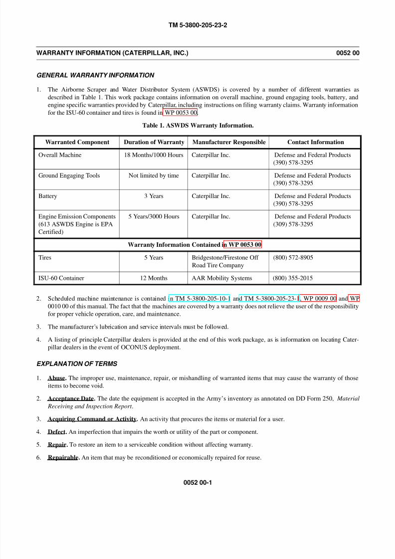
8/14/2019 TM 5-3800-205-23-2 MODEL 613CS
http://slidepdf.com/reader/full/tm-5-3800-205-23-2-model-613cs 245/276
TM 5-3800-205-23-2
0052 00-1
WARRANTY INFORMATION (CATERPILLAR, INC.) 0052 00
GENERAL WARRANTY INFORMATION
1. The Airborne Scraper and Water Distributor System (ASWDS) is covered by a number of different warranties as
described in Table 1. This work package contains information on overall machine, ground engaging tools, battery, andengine specific warranties provided by Caterpillar, including instructions on filing warranty claims. Warranty information
for the ISU-60 container and tires is found in WP 0053 00.
Table 1. ASWDS Warranty Information.
2. Scheduled machine maintenance is contained in TM 5-3800-205-10-1 and TM 5-3800-205-23-1, WP 0009 00 and WP
0010 00 of this manual. The fact that the machines are covered by a warranty does not relieve the user of the responsibility
for proper vehicle operation, care, and maintenance.
3. The manufacturer’s lubrication and service intervals must be followed.
4. A listing of principle Caterpillar dealers is provided at the end of this work package, as is information on locating Cater-
pillar dealers in the event of OCONUS deployment.
EXPLANATION OF TERMS
1. Abuse. The improper use, maintenance, repair, or mishandling of warranted items that may cause the warranty of those
items to become void.
2. Acceptance Date. The date the equipment is accepted in the Army’s inventory as annotated on DD Form 250, Material
Receiving and Inspection Report .
3. Acquiring Command or Activity. An activity that procures the items or material for a user.
4. Defect. An imperfection that impairs the worth or utility of the part or component.
5. Repair. To restore an item to a serviceable condition without affecting warranty.
6. Repairable. An item that may be reconditioned or economically repaired for reuse.
Warranted Component Duration of Warranty Manufacturer Responsible Contact Information
Overall Machine 18 Months/1000 Hours Caterpillar Inc. Defense and Federal Products
(390) 578-3295
Ground Engaging Tools Not limited by time Caterpillar Inc. Defense and Federal Products
(390) 578-3295
Battery 3 Years Caterpillar Inc. Defense and Federal Products(390) 578-3295
Engine Emission Components
(613 ASWDS Engine is EPA
Certified)
5 Years/3000 Hours Caterpillar Inc. Defense and Federal Products
(309) 578-3295
Warranty Information Contained in WP 0053 00
Tires 5 Years Bridgestone/Firestone Off
Road Tire Company
(800) 572-8905
ISU-60 Container 12 Months AAR Mobility Systems (800) 355-2015
8/14/2019 TM 5-3800-205-23-2 MODEL 613CS
http://slidepdf.com/reader/full/tm-5-3800-205-23-2-model-613cs 246/276
TM 5-3800-205-23-2
0052 00-2
WARRANTY INFORMATION (CATERPILLAR, INC.) - CONTINUED 0052 00
EXPLANATION OF TERMS - CONTINUED
7. Warranty. A written agreement between a contractor and the Government that outlines the rights and obligations of both
parties for defective supplies.
8. Warranty Claim. Action started by the equipment users for authorized warranty repair or reimbursement.
9. Warranty Period. Time during which the warranty is in effect.
10. Warranty Start Date. The date the warranty is put into effect (stamped on warranty plate). The warranty plate is proof of
warranty start date for all warranties.
ADMINISTRATIVE INFORMATION
1. Machine Registration. Upon machine handoff to the assigned unit, the warranty plate will be stamped by the local Cater-
pillar dealer with the machine warranty start and end dates. The warranty start date for each machine will then be entered
into the Caterpillar Warranty Database. Entry of the warranty start date activates the coverage for each machine and
allows any Caterpillar dealer worldwide to view the warranty coverage for the machine. This data is accessed by Caterpil-
lar machine serial number.
2. Warranty Questions. Any questions regarding warranty coverage should be directed to Caterpillar, Defense and Federal
Products at (309) 578-3295 or Caterpillar Operator at (309) 675-1000 and ask for Defense and Federal Products.
3. Local Caterpillar Dealer Contact Information. To be completed by Caterpillar Dealer at time of machine delivery.
4. To Obtain Warranty Service. The ASWDS contract provides you with two options (Caterpillar repair or Government
repair) for correcting warranty defects. The choice is the responsibility of the local unit or installation.
a. Caterpillar Repair.
(1) The using unit should contact the local Caterpillar Dealer (locations and phone numbers are available at http://
www.cat.com or in Table 2 at the end of this work package) to coordinate delivery of the machine to the dealer
for analysis or providing for dealer travel to the machine for analysis.
(2) The Caterpillar Dealer will evaluate the problem to determine if the required repair is covered by warranty.
(a) If the required repair is not covered by warranty, the dealer will contact the unit for further instructions and
the unit will be responsible for dealer expenses incurred during machine analysis.
(b) If the required repair is covered by warranty, the dealer will make the repairs and submit claims to Caterpil-
lar for reimbursement.
(3) The Caterpillar dealer will provide travel time and mileage or transportation of the machine as part of the war-
rantable repair.
Dealer Name:
Address:
Point of Contact:
Telephone Number:
Cellular Number:
E-mail Address:

8/14/2019 TM 5-3800-205-23-2 MODEL 613CS
http://slidepdf.com/reader/full/tm-5-3800-205-23-2-model-613cs 247/276
TM 5-3800-205-23-2
0052 00-3
WARRANTY INFORMATION (CATERPILLAR, INC.) - CONTINUED 0052 00
ADMINISTRATIVE INFORMATION - CONTINUED
(4) If the Caterpillar dealer disputes your warranty claim and you feel the claim is valid, contact Caterpillar Defense
and Federal Products at (309) 578-3295 for a review of the claim.
b. Government Repair.
(1) Any warranty repairs made by the user are at the user’s expense.
(2) Government repairs do NOT void Caterpillar warranty. Government is fully responsible for the repair and/or any
maintenance induced failures due to the repair.
5. Warranty Dispute. If Caterpillar Defense and Federal Products declines to perform repairs on items for which you
believe the Government has a valid warranty claim:
a. Perform the repairs yourself; use your own repair parts.
b. Immediately report the situation using DA Form 2407 (or DA Form 5504).
(1) Record “Warranty Dispute” and complete description of the failure.
(2) Enter name, activity, and telephone number of the person submitting the warranty dispute.
(3) Enter the name, address, and telephone number of the Caterpillar representative or dealership that refused the
service.
(4) Give specific reasons for the refusal.
(5) Enter the specific facts/evidence that you feel will disprove Caterpillar’s reason for refusal. Include photographs
and sketches as appropriate.
(6) Submit copies of DA Form 2407 (or DA Form 5504) to: Commander, U.S. Army Tank-automotive and Arma-
ments Command, ATTN: AMSTA-LC-AF-CE, 6501 E. 11 Mile Road, Warren, MI 48397-5000.
6. Caterpillar Responsibilities. If a defect in material or workmanship is found during the warranty period, Caterpillar will,
during normal working hours and at a place of business of a Caterpillar dealer or other source approved by Caterpillar:
a. Provide (at Caterpillar’s choice) new, remanufactured, or Caterpillar-approved repaired parts or assembled compo-
nents needed to correct the defect. Items replaced under this warranty become the property of Caterpillar.
b. Replace lubricating oil, filters, antifreeze, and other service items made unusable by the defect.
c. Provide reasonable and customary labor needed to correct the defect.
7. User Responsibilities.
The user is responsible for the following:
a. Providing proof of the warranty start date if warranty data plate is not available.
b. Labor costs, except as stated under “Caterpillar Responsibilities”.
c. Local taxes, if applicable.
d. Parts shipping charged in excess of those which are usual and customary.
e. Costs to investigate complaints, unless the problem is caused by a defect in Caterpillar material or workmanship.
f. Performance of the required maintenance (including use of proper fuel, oil, lubricants and coolant) and replacement
of items due to normal wear and tear. Failures caused by contaminated fluids are not covered by warranty.
8. Limitations.
Caterpillar is not responsible for failures resulting from:
a. Any use or installation which Caterpillar judges improper.
b. Attachments, accessory items, and parts not sold or approved by Caterpillar.
c. Abuse, neglect, and/or improper repair.

8/14/2019 TM 5-3800-205-23-2 MODEL 613CS
http://slidepdf.com/reader/full/tm-5-3800-205-23-2-model-613cs 248/276
TM 5-3800-205-23-2
0052 00-4
WARRANTY INFORMATION (CATERPILLAR, INC.) - CONTINUED 0052 00
ADMINISTRATION INFORMATION - CONTINUED
d. User’s delay in making the product available after being notified of a potential product problem.
e. Unauthorized repair or adjustments, and unauthorized fuel setting changes.f. Breakage of Ground Engaging Tools (GET) due to worn mating components or those that have been hardfaced or
improperly welded.
g. Remedies under this warranty are limited to providing parts and labor as stated above. Caterpillar is not responsible
for incidental or consequential damages.
OVERALL MACHINE WARRANTY
1. General.
a. The ASWDS machines are covered by Caterpillar’s material and workmanship machine for a period of 18 months or
1,000 hours, whichever occurs first.
b. The warranty period begins on the date of machine handoff to the first using unit. Check the machine data plate for
warranty start date.2. To Obtain Warranty Service. To obtain warranty service, follow procedures outlined above in Administrative Informa-
tion.
GROUND ENGAGING TOOLS (GET) WARRANTY
1. General.
a. Caterpillar GET is covered by warranty by Caterpillar Inc.
b. The warranty period is not limited by time and is applicable throughout the useful life of the ground engaging tools
covered. GET is considered worn out when it is no longer protecting the structural surface to which the GET is
mounted.
2. To Obtain Warranty Service. To obtain warranty service on GET, follow procedures outlined above in Administrative
Information.
3. Specific Warranty Information.
a. The Caterpillar warranty is applicable after the expiration of any standard machine or parts warranty. The following
Caterpillar GET are covered:
(1) Cutting edge (P/N 4T6611)
(2) Cutting edge (P/N 4T6613)
(3) Router bits (P/N 4T4336)
b. After the machine warranty period, the unit is responsible for all labor (including welding) and hardware costs associ-
ated with removal and installation of GET. The unit is also responsible for delivering the hardware to the dealer and
getting replacement GET.
BATTERY WARRANTY 1. General. The battery is covered by 3 year warranty by Caterpillar Inc.
2. To Obtain Warranty Service. To obtain warranty service on the battery, follow procedures outlined above in Administra-
tive Information.
3. Specific Warranty Information.
a. Caterpillar will replace the battery which it finds to be defective in material or workmanship with a new battery at the
following cost to the user:
(1) For the first 12 months from machine warranty start date there is not charge to the user.
8/14/2019 TM 5-3800-205-23-2 MODEL 613CS
http://slidepdf.com/reader/full/tm-5-3800-205-23-2-model-613cs 249/276
TM 5-3800-205-23-2
0052 00-5
WARRANTY INFORMATION (CATERPILLAR, INC.) - CONTINUED 0052 00
BATTERY WARRANTY - CONTINUED
(2) After 12 months from machine warranty start date, user cost is determined by the following formula:
b. This warranty will be honored upon return of the battery, during normal working hours, to a Caterpillar dealer or
other source approved by Caterpillar.
EMISSIONS WARRANTY
NOTE
• California users must also refer to Emission Control Warranty for California .
• Certification tags illustrated are sample tags only and may not reflect the tags found on your machine.
• Items covered by the emission warranty are:
• Fuel injector group
• Fuel-air ratio control (FRC) and FRC boost line
• Unit injector governor group
• Fuel injector control assembly
• Turbocharger and gasket
• Intake manifold and gasket
• Exhaust manifold and gasket
• Turbocharger-to-aftercooler hoses and clamps
• Engine inlet air aftercooler and gasket.1. General.
a. Caterpillar Inc. or any of its subsidiaries (“Caterpillar”) warrants that certified nonroad diesel engine (powering
mobile machinery) are:
(1) Designed, built, and equipped so as to conform, at the time of sale, with all applicable regulations adopted by the
United States Environmental Protection Agency (EPA).
(2) Free from defects in materials and workmanship in specific emission-related parts for a period of 60 months, or
3,000 hours of operation, whichever occurs first, after the date of delivery to the first user.
b. If an emission-related part fails during the warranty period, it will be repaired, or replaced. Any such part repaired or
replaced under warranty is warranted for the remainder of the warranty period.
c. The engine is certified if it has a special certification label. A Caterpillar dealer can also inform you if the engine is
certified.
d. During the term of this warranty, Caterpillar will provide, through a Caterpillar dealer or other source approved by it,
repair or replacement of any warranted part at no charge.
e. In an emergency, repairs may be performed at any service establishment, or by the user. Caterpillar will reimburse the
user for their expenses, including diagnostic charges for such emergency repair. These expenses shall not exceed Cat-
erpillar’s suggested retail price for all warranted parts replaced, and labor charges based on Caterpillar’s recom-
mended time allowance for the warranty repair and the geographically appropriate hourly labor rate.
f. A part not being available within 30 days or a repair not being complete within 30 days constitutes an emergency.
Current Customer’s Battery Price x Months in Service
36 (months in battery warranty)= User Cost
8/14/2019 TM 5-3800-205-23-2 MODEL 613CS
http://slidepdf.com/reader/full/tm-5-3800-205-23-2-model-613cs 250/276
TM 5-3800-205-23-2
0052 00-6
WARRANTY INFORMATION (CATERPILLAR, INC.) - CONTINUED 0052 00
EMISSIONS WARRANTY - CONTINUED
g. As a condition of reimbursement, replaced parts and validated invoices must be presented at a place of business of a
Caterpillar dealer or other source approved by Caterpillar.
2. Responsibilities and Limitations. The warranty is subject to the following:
a. Caterpillar Responsibilities. During the emission warranty period, if a defect in material or workmanship of an
emission-related part or component is found, Caterpillar will provide:
(1) New, remanufactured, or repaired parts and/or components, approved pursuant to EPA Regulations, required to
correct the defect.
(2) Note: Items replaced under warranty become the property of Caterpillar.
(3) Reasonable or customary labor, during normal working hours, needed to correct the defect, including labor for
removal and installation when necessary to make the repair.
b. User Responsibilities. During the emission warranty period, the user is responsible for:
(1) Providing proof of the delivery date to the first user.
(2) Premium or overtime labor costs.
(3) Costs to investigate complaints which are not caused by a defect in Caterpillar material or workmanship.
(4) Providing timely notice or a warrantable failure and promptly making the product available for repair.
(5) Performance of the required maintenance and use of proper fuel, oil, lubricants and coolant.
(6) Maintenance, replacement, or repair of the emission control devices and systems may be performed by any non-
road engine repair establishment or individual using certified nonroad engine parts.
3. Limitations.
a. Caterpillar is not responsible for resultant damages to an emission-related part of component resulting from:
(1) Any use or installation which Caterpillar judges improper.
(2) Attachments, accessory items and parts not sold or approved by Caterpillar.
(3) Abuse, neglect and/or improper engine repair.
(4) User’s delay in making the product available after being notified of a potential product problem.
(5) Unauthorized repair or adjustments and unauthorized fuel setting changes.
b. This warranty is in addition to Caterpillar’s standard warranty, applicable to the nonroad diesel engine product
involved.
c. NEITHER THE FOREGOING EXPRESS WARRANTY NOR ANY OTHER WARRANTY BY CATERPILLAR,
EXPRESS OR IMPLIED, IS APPLICABLE TO ANY ITEM CATERPILLAR SELLS WHICH IS WARRANTED
DIRECTLY TO THE USER BY ITS MANUFACTURER.
d. THIS WARRANTY IS EXPRESSLY IN LIEU OF ANY OTHER WARRANTIES, EXPRESS OR IMPLIED,
INCLUDING ANY WARRANTY OF MERCHANTABILITY OR FITNESS FOR A PARTICULAR PURPOSE.
REMEDIES UNDER THIS WARRANTY ARE LIMITED TO THE PROVISION OF MATERIAL AND SER-
VICES, AS SPECIFIED HEREIN. CATERPILLAR IS NOT RESPONSIBLE FOR INCIDENTAL OR CONSE-
QUENTIAL DAMAGES.
4. Maintenance Recommendations.
a. Some Caterpillar nonroad diesel engines are certified by the United States EPA to comply with smoke and gaseous
emission standards prescribed by Federal laws at the time of manufacture.
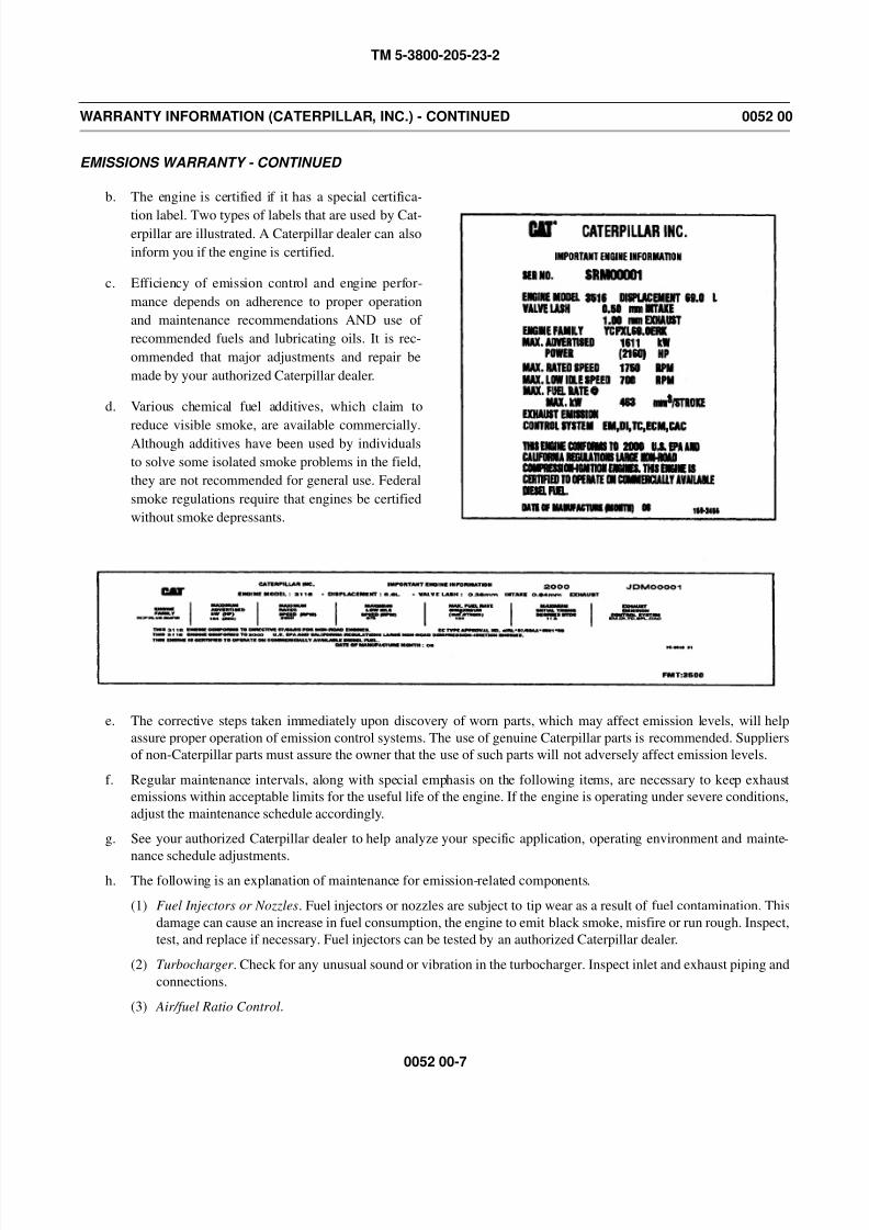
8/14/2019 TM 5-3800-205-23-2 MODEL 613CS
http://slidepdf.com/reader/full/tm-5-3800-205-23-2-model-613cs 251/276
TM 5-3800-205-23-2
0052 00-7
WARRANTY INFORMATION (CATERPILLAR, INC.) - CONTINUED 0052 00
EMISSIONS WARRANTY - CONTINUED
b. The engine is certified if it has a special certifica-
tion label. Two types of labels that are used by Cat-erpillar are illustrated. A Caterpillar dealer can also
inform you if the engine is certified.
c. Efficiency of emission control and engine perfor-
mance depends on adherence to proper operation
and maintenance recommendations AND use of
recommended fuels and lubricating oils. It is rec-
ommended that major adjustments and repair be
made by your authorized Caterpillar dealer.
d. Various chemical fuel additives, which claim to
reduce visible smoke, are available commercially.Although additives have been used by individuals
to solve some isolated smoke problems in the field,
they are not recommended for general use. Federal
smoke regulations require that engines be certified
without smoke depressants.
e. The corrective steps taken immediately upon discovery of worn parts, which may affect emission levels, will help
assure proper operation of emission control systems. The use of genuine Caterpillar parts is recommended. Suppliers
of non-Caterpillar parts must assure the owner that the use of such parts will not adversely affect emission levels.
f. Regular maintenance intervals, along with special emphasis on the following items, are necessary to keep exhaust
emissions within acceptable limits for the useful life of the engine. If the engine is operating under severe conditions,
adjust the maintenance schedule accordingly.
g. See your authorized Caterpillar dealer to help analyze your specific application, operating environment and mainte-
nance schedule adjustments.h. The following is an explanation of maintenance for emission-related components.
(1) Fuel Injectors or Nozzles. Fuel injectors or nozzles are subject to tip wear as a result of fuel contamination. This
damage can cause an increase in fuel consumption, the engine to emit black smoke, misfire or run rough. Inspect,
test, and replace if necessary. Fuel injectors can be tested by an authorized Caterpillar dealer.
(2) Turbocharger . Check for any unusual sound or vibration in the turbocharger. Inspect inlet and exhaust piping and
connections.
(3) Air/fuel Ratio Control.

8/14/2019 TM 5-3800-205-23-2 MODEL 613CS
http://slidepdf.com/reader/full/tm-5-3800-205-23-2-model-613cs 252/276
TM 5-3800-205-23-2
0052 00-8
WARRANTY INFORMATION (CATERPILLAR, INC.) - CONTINUED 0052 00
EMISSIONS WARRANTY - CONTINUED
(a) This component is a device to control the black smoke emission of an engine during its operation when low
inlet manifold pressure exists.
(b) Slow engine response and low power may indicate a need for adjustment or repair. Your Caterpillar dealer is
equipped with the necessary tools, personnel, and procedures to perform this service.
(c) The owner is encouraged to keep adequate maintenance records, but the absence of such, in and of itself,
will not invalidate the warranty.
(d) The machine or equipment owner may perform routine maintenance, repairs and other non-warranty work or
have it done at any repair facility. Such non-warranty work need not be performed at a designated warranty
station in order for the warranty to remain in force.
5. Customer Assistance - Emission Control Systems Warranty.
a. Caterpillar Inc. aims to ensure that the Emission Control System warranty is properly administered. In the event that
you do not receive the warranty service to which you believe you are entitled under the Emission Control Systems
Warranty, call or write: Caterpillar, Manager of Warranty Systems, Peoria, IL 61629-1250; (309) 675-4037.
b. Authorized dealers are recommended for major maintenance and repair work as they are staffed with trained person-
nel, proper tools and are aware of the latest maintenance methods and procedures. Owners and others who desire to
perform their own work should purchase a Service Manual and obtain current service information from their Caterpil-
lar dealer.
EMISSION CONTROL WARRANTY FOR CALIFORNIA
1. Owner Warranty Rights and Obligations.
a. The California Air Resources Board (CARB) and Caterpillar are pleased to explain the emission control system war-
ranty on your 2000 or later certified heavy duty off-road diesel engine. The engine is certified if it has a special certi-
fication label. Two types of labels that are used by Caterpillar are shown on previous pages. A Caterpillar dealer can
also inform you if the engine is certified.
b. In California, new heavy duty off-road diesel engines must be designed, built, and equipped to meet the state’s strin-
gent anti-smog standards. Caterpillar must warrant the emission control system on your engine for the duration of time listed below provided there has been no abuse, neglect, or improper maintenance on your engine.
c. Your emission control system may include parts such as the fuel injection system, air induction system, and engine
computer, if equipped. Also included may be hoses, connectors, clamps, and other emission-related components.
d. Where a warrantable condition exists, Caterpillar will repair the heavy duty off-road diesel engine at no cost to the
owner including diagnosis, parts, and labor.
2. Manufacturer’s Warranty Coverage.
a. The emissions warranty period for new heavy duty off-road diesel engines is a duration of 60 months, or 3,000 hours
of operation, whichever occurs first after date of delivery to the initial owner.
b. If an emission-related part or component on your diesel engine is defective, the part or component will be repaired, or
replaced by Caterpillar. This is your emission control system WARRANTY.
c. This warranty covers the following emission-related parts and components:
(1) Charge Air Cooling System (if equipped)
(2) Fuel Injection System
(3) Intake Manifold
(4) Exhaust Manifold
(5) Turbocharger System
(6) Air-Fuel Ratio Control System
(7) Electronic Control Module including Sensors and Personality Module (if equipped)
8/14/2019 TM 5-3800-205-23-2 MODEL 613CS
http://slidepdf.com/reader/full/tm-5-3800-205-23-2-model-613cs 253/276
TM 5-3800-205-23-2
0052 00-9
WARRANTY INFORMATION (CATERPILLAR, INC.) - CONTINUED 0052 00
EMISSION CONTROL WARRANTY FOR CALIFORNIA - CONTINUED
(8) Miscellaneous hoses, clamps, connectors and sealing devices used in the above systems.
d. Any replacement part may be used for maintenance or repairs. The owner should ensure that such parts are equivalentin design and durability to genuine Caterpillar parts. Use of non-genuine Caterpillar parts does not invalidate the war-
ranty. However, Caterpillar is not liable for parts which are not genuine Caterpillar parts.
3. Owner’s Warranty Responsibilities.
a. As the heavy duty off-road diesel engine owner, you are responsible for the performance of the required maintenance
listed in the owner’s manual (Operation and Maintenance Manual). Caterpillar recommends that you retain all
records covering the maintenance on your engine, but cannot deny warranty solely for lack of receipts and records or
for failure to ensure the performance of all scheduled maintenance.
b. As the heavy duty off-road diesel engine owner, you should also be aware that Caterpillar may deny you warranty
coverage if your heavy duty off-road diesel engine, or an emission components, or part has failed due to abuse,
neglect, improper maintenance or unapproved modifications.
c. Your engine is designed to operate on commercial diesel fuel only. Use of any other fuel may result in your engine no
longer operating in compliance with California’s emission requirements.
d. You are responsible for contacting your Caterpillar dealer as soon as any engine problem exists. The warranty repairs
should be completed in a reasonable amount of time, not to exceed 30 days.
e. If you have questions regarding your warranty rights and responsibilities contact: Caterpillar Manager, Warranty
Operations, Peoria, IL 61629-1250, phone: (309) 675-4037 or California Air Resources Board (CARB), 9528 Telstar
Ave., El Monte, CA 91731.
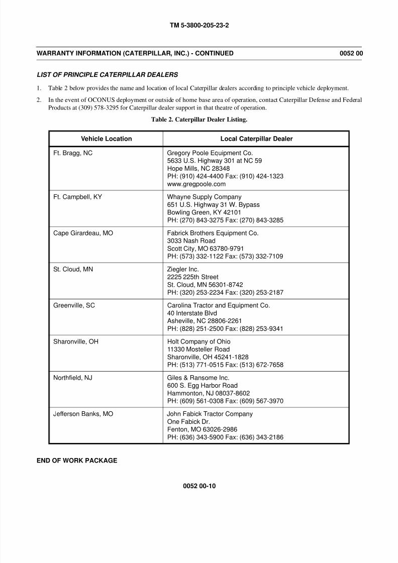
8/14/2019 TM 5-3800-205-23-2 MODEL 613CS
http://slidepdf.com/reader/full/tm-5-3800-205-23-2-model-613cs 254/276
TM 5-3800-205-23-2
0052 00-10
WARRANTY INFORMATION (CATERPILLAR, INC.) - CONTINUED 0052 00
LIST OF PRINCIPLE CATERPILLAR DEALERS
1. Table 2 below provides the name and location of local Caterpillar dealers according to principle vehicle deployment.
2. In the event of OCONUS deployment or outside of home base area of operation, contact Caterpillar Defense and FederalProducts at (309) 578-3295 for Caterpillar dealer support in that theatre of operation.
Table 2. Caterpillar Dealer Listing.
END OF WORK PACKAGE
Vehicle Location Local Caterpillar Dealer
Ft. Bragg, NC Gregory Poole Equipment Co.5633 U.S. Highway 301 at NC 59
Hope Mills, NC 28348PH: (910) 424-4400 Fax: (910) 424-1323
www.gregpoole.com
Ft. Campbell, KY Whayne Supply Company651 U.S. Highway 31 W. BypassBowling Green, KY 42101
PH: (270) 843-3275 Fax: (270) 843-3285
Cape Girardeau, MO Fabrick Brothers Equipment Co.3033 Nash Road
Scott City, MO 63780-9791PH: (573) 332-1122 Fax: (573) 332-7109
St. Cloud, MN Ziegler Inc.2225 225th Street
St. Cloud, MN 56301-8742
PH: (320) 253-2234 Fax: (320) 253-2187Greenville, SC Carolina Tractor and Equipment Co.
40 Interstate BlvdAsheville, NC 28806-2261
PH: (828) 251-2500 Fax: (828) 253-9341
Sharonville, OH Holt Company of Ohio11330 Mosteller Road
Sharonville, OH 45241-1828PH: (513) 771-0515 Fax: (513) 672-7658
Northfield, NJ Giles & Ransome Inc.600 S. Egg Harbor Road
Hammonton, NJ 08037-8602PH: (609) 561-0308 Fax: (609) 567-3970
Jefferson Banks, MO John Fabick Tractor Company
One Fabick Dr.Fenton, MO 63026-2986
PH: (636) 343-5900 Fax: (636) 343-2186
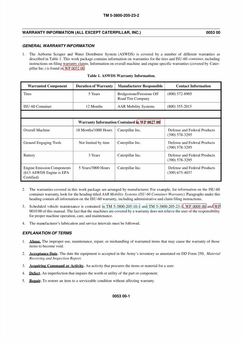
8/14/2019 TM 5-3800-205-23-2 MODEL 613CS
http://slidepdf.com/reader/full/tm-5-3800-205-23-2-model-613cs 255/276
TM 5-3800-205-23-2
0053 00-1
WARRANTY INFORMATION (ALL EXCEPT CATERPILLAR, INC.) 0053 00
GENERAL WARRANTY INFORMATION
1. The Airborne Scraper and Water Distributor System (ASWDS) is covered by a number of different warranties as
described in Table 1. This work package contains information on warranties for the tires and ISU-60 container, includinginstructions on filing warranty claims. Information on overall machine and engine specific warranties (covered by Cater-
pillar Inc.) is found in WP 0052 00.
Table 1. ASWDS Warranty Information.
2. The warranties covered in this work package are arranged by manufacturer. For example, for information on the ISU-60
container warranty, look for the heading titled AAR Mobility Systems (ISU-60 Container Warranty). Paragraphs under this
heading contain all information on the ISU-60 warranty, including administrative and claim filing instructions.
3. Scheduled vehicle maintenance is contained in TM 5-3800-205-10-1 and TM 5-3800-205-23-1, WP 0009 00 and WP
0010 00 of this manual. The fact that the machines are covered by a warranty does not relieve the user of the responsibility
for proper machine operation, care, and maintenance.
4. The manufacturer’s lubrication and service intervals must be followed.
EXPLANATION OF TERMS
1. Abuse. The improper use, maintenance, repair, or mishandling of warranted items that may cause the warranty of thoseitems to become void.
2. Acceptance Date. The date the equipment is accepted in the Army’s inventory as annotated on DD Form 250, Material
Receiving and Inspection Report .
3. Acquiring Command or Activity. An activity that procures the items or material for a user.
4. Defect. An imperfection that impairs the worth or utility of the part or component.
5. Repair. To restore an item to a serviceable condition without affecting warranty.
Warranted Component Duration of Warranty Manufacturer Responsible Contact Information
Tires 5 Years Bridgestone/Firestone Off
Road Tire Company
(800) 572-8905
ISU-60 Container 12 Months AAR Mobility Systems (800) 355-2015
Warranty Information Contained in WP 0027 00
Overall Machine 18 Months/1000 Hours Caterpillar Inc. Defense and Federal Products
(390) 578-3295
Ground Engaging Tools Not limited by time Caterpillar Inc. Defense and Federal Products
(390) 578-3295
Battery 3 Years Caterpillar Inc. Defense and Federal Products
(390) 578-3295
Engine Emission Components
(613 ASWDS Engine is EPA
Certified)
5 Years/3000 Hours Caterpillar Inc. Defense and Federal Products
(309) 675-4037
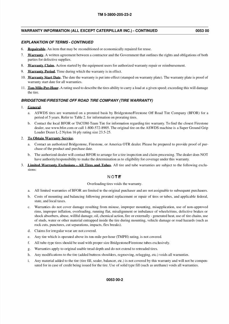
8/14/2019 TM 5-3800-205-23-2 MODEL 613CS
http://slidepdf.com/reader/full/tm-5-3800-205-23-2-model-613cs 256/276
TM 5-3800-205-23-2
0053 00-2
WARRANTY INFORMATION (ALL EXCEPT CATERPILLAR INC.) - CONTINUED 0053 00
EXPLANATION OF TERMS - CONTINUED
6. Repairable. An item that may be reconditioned or economically repaired for reuse.
7. Warranty. A written agreement between a contractor and the Government that outlines the rights and obligations of bothparties for defective supplies.
8. Warranty Claim. Action started by the equipment users for authorized warranty repair or reimbursement.
9. Warranty Period. Time during which the warranty is in effect.
10. Warranty Start Date. The date the warranty is put into effect (stamped on warranty plate). The warranty plate is proof of
warranty start date for all warranties.
11. Ton-Mile-Per-Hour. A rating used to describe the tires ability to carry a load at a given speed; exceeding this will damage
the tire.
BRIDGETONE/FIRESTONE OFF ROAD TIRE COMPANY (TIRE WARRANTY)
1. General.
a. ASWDS tires are warranted on a prorated basis by Bridgestone/Firestone Off Road Tire Company (BFOR) for aperiod of 5 years. Refer to Table 2. for information on prorating tires.
b. Contact the local BFOR or TACOM-Team Tire for information regarding tire warranty. To find the closest Firestone
dealer, use www.bfor.com or call 1-800-572-8905. The original tire on the ASWDS machine is a Super Ground Grip
Loader Dozer L-2 Nylon 16 ply rating size 23.5-25.
2. To Obtain Warranty Service.
a. Contact an authorized Bridgestone, Firestone, or America OTR dealer. Please be prepared to provide proof of pur-
chase of the product and purchase date.
b. The authorized dealer will contact BFOR to arrange for a tire inspection and claim processing. The dealer does NOT
have authority/responsibility to make the determination as to eligibility for coverage under this warranty.
3. Limited Warranty Exclusions - All Tires and Tubes. All tire and tube warranties are subject to the following exclu-
sions:
NOTE
Overloading tires voids the warranty.
a. All limited warranties of BFOR are limited to the original purchaser and are not assignable to subsequent purchasers.
b. Costs of mounting and balancing following prorated replacement or repair of tires or tubes, and applicable federal,
state, and local taxes.
c. Warranties do not cover damage resulting from misuse, improper mounting, misapplication, use of non-approved
rims, improper inflation, overloading, running flat, misalignment or imbalance of wheels/rims, defective brakes or
shock absorbers, abuse, willful damage, oil, chemical action, fire or externally - generated heat, use of tire chains, use
of studs, water or other material entrapped inside the tire during mounting, vehicle damage or road hazards (such as
rock cuts, punctures, cut separations, impacts, flex breaks).
d. Claims for irregular wear are not covered.
e. Any tire which is operated above its ton-mile per-hour (TMPH) rating, is not covered.
f. All tube-type tires should be used with proper size Bridgestone/Firestone tubes exclusively.
g. Warranties apply to original usable tread depth and do not extend to retreaded tires.
h. Any modifications to the tire (added buttress shoulders, regrooving, relugging, etc.) voids all warranties.
i. Any material added to the tire (tire fill, sealer, balancer, etc.) is not covered by this warranty and will not be compen-
sated for in case of credit being issued for the tire. Use of solid type fill (such as urethane) voids all warranties.

8/14/2019 TM 5-3800-205-23-2 MODEL 613CS
http://slidepdf.com/reader/full/tm-5-3800-205-23-2-model-613cs 257/276
TM 5-3800-205-23-2
0053 00-3
WARRANTY INFORMATION (ALL EXCEPT CATERPILLAR INC.) - CONTINUED 0053 00
BRIDGETONE/FIRESTONE OFF ROAD TIRE COMPANY (TIRE WARRANTY) - CONTINUED
j. Any costs associated with the repair of tires are not covered, unless previously approved by the appropriate BFOR
employee.
k. Warranties are valid only for tires and tubes purchased and used in the United States.
l. ALL IMPLIED WARRANTIES, INCLUDING WARRANTIES OF MERCHANTABILITY AND FITNESS FOR A
PARTICULAR PURPOSE ARE EXPRESSLY LIMITED TO THE DURATION OF THIS LIMITED WARRANTY.
m. ALL OBLIGATIONS OR LIABILITIES FOR INCIDENTAL OR CONSEQUENTIAL DAMAGE ARE HEREBY
EXCLUDED, INCLUDING LOSS OF USE OF VEHICLE AND LOSS OF TIME.
n. Some states do not allow limitations in how long an implied warranty lasts, or the exclusion or limitation of incidental
or consequential damages, so the above such limitations or exclusions may not apply to you.
o. No Bridgestone, Firestone, or America OTR dealer has the authority to make or imply any representation, promise or
agreement which in any way varies or extends the terms of this warranty.
Table 2. Tire Warranty Information.
AAR MOBILITY SYSTEMS (ISU-60 CONTAINER WARRANTY)
1. General. The ISU-60 container is covered by a 12-month materials and workmanship warranty by AAR Mobility Sys-
tems.
2. To Obtain Warranty Service. Contact AAR Mobility Systems at 1-800-355-2015.
AMOUNT OF CREDIT ISSUED TO THE CUSTOMER FOR WORKMANSHIP AND MATERIAL CONDITIONS
Percentage of Original Tread Depth Remaining
AGE OF TIRE
81% to
100%
71% to
80%
61% to
70%
51% to
60%
41% to
50%
31% to
40%
21% to
30%
0% to
20%
Less than 180 days Actual% 70% 60% 50% 40% 30% 20% 0%
180 days to one year 80% 70% 60% 50% 40% 30% 10% 0%
Less than two years 75% 65% 60% 50% 40% 30% 10% 0%
Less than three years 50% 50% 40% 40% 40% 30% 10% 0%
Less than four years 40% 30% 30% 30% 30% 20% 10% 0%
Less than five years 20% 20% 20% 20% 20% 20% 10% 0%
More than five years 0% 0% 0% 0% 0% 0% 0% 0%

8/14/2019 TM 5-3800-205-23-2 MODEL 613CS
http://slidepdf.com/reader/full/tm-5-3800-205-23-2-model-613cs 258/276
TM 5-3800-205-23-2
0053 00-4
WARRANTY INFORMATION (ALL EXCEPT CATERPILLAR INC.) - CONTINUED 0053 00
AAR MOBILITY SYSTEMS (ISU-60 CONTAINER WARRANTY) - CONTINUED
3. ISU-60 Container Warranty. AAR warrants to the Army that its new goods, excluding components not made by AAR,
are free from defects in material and workmanship under normal use and service. AAR’s obligation under this warranty is
limited to repair or at AAR’s option, replacement of any part or parts which are within 12 months after delivery to theArmy returned to AAR’s place of manufacture and which after examination appears to AAR’s satisfaction to be defective
under the above warranty. In the event a part is replaced, the aforementioned warranty term shall not be extended beyond
one year after the delivery of the original manufactured part to the Army. All costs of shipping any defective goods to
AAR and returning them to the Army shall be borne entirely by the Army. AAR shall use its good faith efforts to obtain,
in its subcontract with each supplier of components not made by AAR, a provision that the subcontractor’s standard war-
ranty, if any, shall survive AAR’s inspection, acceptance and payment and shall run to AAR, its successors, assigns and
customers. AAR MAKES NO IMPLIED WARRANTY OF MERCHANTABILITY FITNESS FOR ANY SPECIAL USE
OR FUNCTION OR LIFE AFTER SALE TO THE ARMY AND/OR TO SUBSEQUENT BUYERS OR USERS OF
THE GOODS, BEYOND THE EXPRESSED TERMS OF THIS AGREEMENT. THERE ARE NO WARRANTIES
EXPRESSED OR IMPLIED, ARISING FROM COURSE OF DEALING, COURSE OF PERFORMANCE OR USAGE
OF TRADE, WHICH EXTEND BEYOND THE FACE OF THIS AGREEMENT. AAR neither assumes nor authorizes
any person to assume for it any other liability in connection with the sale of its goods.
END OF WORK PACKAGE
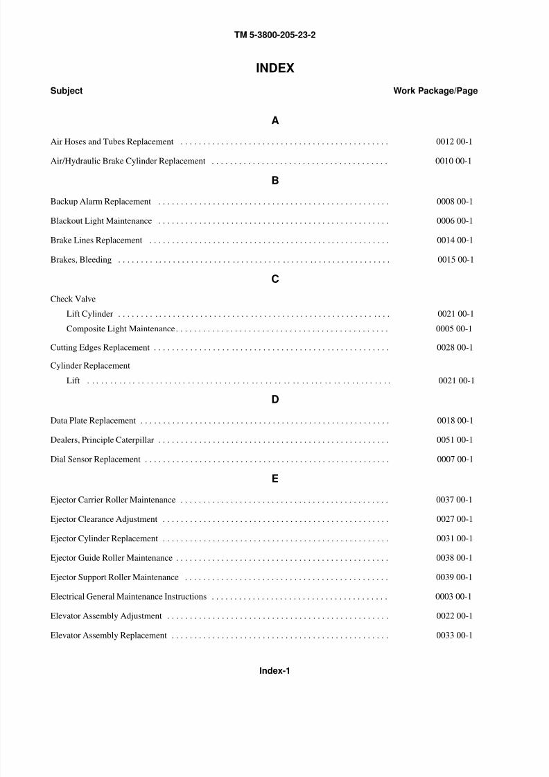
8/14/2019 TM 5-3800-205-23-2 MODEL 613CS
http://slidepdf.com/reader/full/tm-5-3800-205-23-2-model-613cs 259/276
TM 5-3800-205-23-2
Index-1
INDEX
Subject Work Package/Page
A
Air Hoses and Tubes Replacement . . . . . . . . . . . . . . . . . . . . . . . . . . . . . . . . . . . . . . . . . . . . . . 0012 00-1
Air/Hydraulic Brake Cylinder Replacement . . . . . . . . . . . . . . . . . . . . . . . . . . . . . . . . . . . . . . . 0010 00-1
B
Backup Alarm Replacement . . . . . . . . . . . . . . . . . . . . . . . . . . . . . . . . . . . . . . . . . . . . . . . . . . . 0008 00-1
Blackout Light Maintenance . . . . . . . . . . . . . . . . . . . . . . . . . . . . . . . . . . . . . . . . . . . . . . . . . . . 0006 00-1
Brake Lines Replacement . . . . . . . . . . . . . . . . . . . . . . . . . . . . . . . . . . . . . . . . . . . . . . . . . . . . . 0014 00-1
Brakes, Bleeding . . . . . . . . . . . . . . . . . . . . . . . . . . . . . . . . . . . . . . . . . . . . . . . . . . . . . . . . . . . . 0015 00-1
C
Check Valve
Lift Cylinder . . . . . . . . . . . . . . . . . . . . . . . . . . . . . . . . . . . . . . . . . . . . . . . . . . . . . . . . . . . . 0021 00-1
Composite Light Maintenance. . . . . . . . . . . . . . . . . . . . . . . . . . . . . . . . . . . . . . . . . . . . . . . 0005 00-1
Cutting Edges Replacement . . . . . . . . . . . . . . . . . . . . . . . . . . . . . . . . . . . . . . . . . . . . . . . . . . . . 0028 00-1
Cylinder Replacement
Lift . . . . . . . . . . . . . . . . . . . . . . . . . . . . . . . . . . . . . . . . . . . . . . . . . . . . . . . . . . . . . . . . . . . 0021 00-1
D
Data Plate Replacement . . . . . . . . . . . . . . . . . . . . . . . . . . . . . . . . . . . . . . . . . . . . . . . . . . . . . . . 0018 00-1
Dealers, Principle Caterpillar . . . . . . . . . . . . . . . . . . . . . . . . . . . . . . . . . . . . . . . . . . . . . . . . . . . 0051 00-1
Dial Sensor Replacement . . . . . . . . . . . . . . . . . . . . . . . . . . . . . . . . . . . . . . . . . . . . . . . . . . . . . . 0007 00-1
E
Ejector Carrier Roller Maintenance . . . . . . . . . . . . . . . . . . . . . . . . . . . . . . . . . . . . . . . . . . . . . . 0037 00-1
Ejector Clearance Adjustment . . . . . . . . . . . . . . . . . . . . . . . . . . . . . . . . . . . . . . . . . . . . . . . . . . 0027 00-1
Ejector Cylinder Replacement . . . . . . . . . . . . . . . . . . . . . . . . . . . . . . . . . . . . . . . . . . . . . . . . . . 0031 00-1
Ejector Guide Roller Maintenance . . . . . . . . . . . . . . . . . . . . . . . . . . . . . . . . . . . . . . . . . . . . . . . 0038 00-1
Ejector Support Roller Maintenance . . . . . . . . . . . . . . . . . . . . . . . . . . . . . . . . . . . . . . . . . . . . . 0039 00-1
Electrical General Maintenance Instructions . . . . . . . . . . . . . . . . . . . . . . . . . . . . . . . . . . . . . . . 0003 00-1
Elevator Assembly Adjustment . . . . . . . . . . . . . . . . . . . . . . . . . . . . . . . . . . . . . . . . . . . . . . . . . 0022 00-1
Elevator Assembly Replacement . . . . . . . . . . . . . . . . . . . . . . . . . . . . . . . . . . . . . . . . . . . . . . . . 0033 00-1
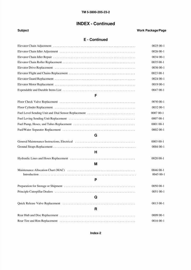
8/14/2019 TM 5-3800-205-23-2 MODEL 613CS
http://slidepdf.com/reader/full/tm-5-3800-205-23-2-model-613cs 260/276
TM 5-3800-205-23-2
Index-2
INDEX - Continued
Subject Work Package/Page
E - Continued
Elevator Chain Adjustment . . . . . . . . . . . . . . . . . . . . . . . . . . . . . . . . . . . . . . . . . . . . . . . . . . . . 0025 00-1Elevator Chain Idler Adjustment . . . . . . . . . . . . . . . . . . . . . . . . . . . . . . . . . . . . . . . . . . . . . . . . 0026 00-1
Elevator Chain Idler Repair . . . . . . . . . . . . . . . . . . . . . . . . . . . . . . . . . . . . . . . . . . . . . . . . . . . . 0034 00-1
Elevator Chain Roller Replacement . . . . . . . . . . . . . . . . . . . . . . . . . . . . . . . . . . . . . . . . . . . . . . 0035 00-1
Elevator Drive Replacement . . . . . . . . . . . . . . . . . . . . . . . . . . . . . . . . . . . . . . . . . . . . . . . . . . . 0036 00-1
Elevator Flight and Chains Replacement . . . . . . . . . . . . . . . . . . . . . . . . . . . . . . . . . . . . . . . . . . 0023 00-1
Elevator Guard Replacement . . . . . . . . . . . . . . . . . . . . . . . . . . . . . . . . . . . . . . . . . . . . . . . . . . . 0024 00-1
Elevator Motor Replacement . . . . . . . . . . . . . . . . . . . . . . . . . . . . . . . . . . . . . . . . . . . . . . . . . . . 0019 00-1
Expendable and Durable Items List . . . . . . . . . . . . . . . . . . . . . . . . . . . . . . . . . . . . . . . . . . . . . . 0047 00-1
F
Floor Check Valve Replacement . . . . . . . . . . . . . . . . . . . . . . . . . . . . . . . . . . . . . . . . . . . . . . . . 0030 00-1
Floor Cylinder Replacement . . . . . . . . . . . . . . . . . . . . . . . . . . . . . . . . . . . . . . . . . . . . . . . . . . . 0032 00-1
Fuel Level Sending Unit and Dial Sensor Replacement . . . . . . . . . . . . . . . . . . . . . . . . . . . . . . 0007 00-1
Fuel Leving Sending Unit Replacement . . . . . . . . . . . . . . . . . . . . . . . . . . . . . . . . . . . . . . . . . . 0007 00-1
Fuel Pump, Hoses, and Tubes Replacement . . . . . . . . . . . . . . . . . . . . . . . . . . . . . . . . . . . . . . . 0001 00-1
Fuel/Water Separator Replacement . . . . . . . . . . . . . . . . . . . . . . . . . . . . . . . . . . . . . . . . . . . . . . 0002 00-1
G
General Maintenance Instructions, Electrical . . . . . . . . . . . . . . . . . . . . . . . . . . . . . . . . . . . . . . 0003 00-1
Ground Straps Replacement . . . . . . . . . . . . . . . . . . . . . . . . . . . . . . . . . . . . . . . . . . . . . . . . . . . . 0004 00-1
H
Hydraulic Lines and Hoses Replacement . . . . . . . . . . . . . . . . . . . . . . . . . . . . . . . . . . . . . . . . . 0020 00-1
M
Maintenance Allocation Chart (MAC) . . . . . . . . . . . . . . . . . . . . . . . . . . . . . . . . . . . . . . . . . . . 0046 00-1
Introduction . . . . . . . . . . . . . . . . . . . . . . . . . . . . . . . . . . . . . . . . . . . . . . . . . . . . . . . . . . . . . 0045 00-1
P
Preparation for Storage or Shipment . . . . . . . . . . . . . . . . . . . . . . . . . . . . . . . . . . . . . . . . . . . . . 0050 00-1
Principle Caterpillar Dealers . . . . . . . . . . . . . . . . . . . . . . . . . . . . . . . . . . . . . . . . . . . . . . . . . . . 0051 00-1
Q
Quick Release Valve Replacement . . . . . . . . . . . . . . . . . . . . . . . . . . . . . . . . . . . . . . . . . . . . . . 0013 00-1
R
Rear Hub and Disc Replacement . . . . . . . . . . . . . . . . . . . . . . . . . . . . . . . . . . . . . . . . . . . . . . . . 0009 00-1
Rear Tire and Rim Replacement . . . . . . . . . . . . . . . . . . . . . . . . . . . . . . . . . . . . . . . . . . . . . . . . 0016 00-1
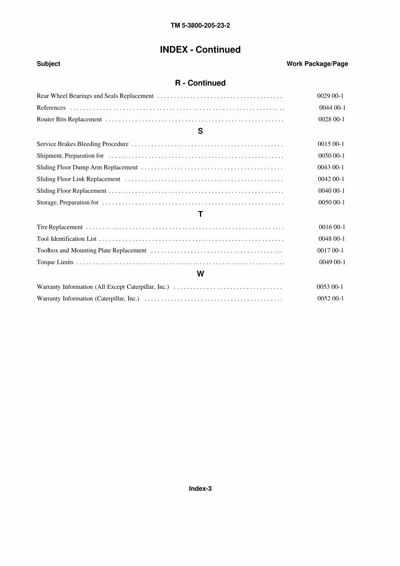
8/14/2019 TM 5-3800-205-23-2 MODEL 613CS
http://slidepdf.com/reader/full/tm-5-3800-205-23-2-model-613cs 261/276
TM 5-3800-205-23-2
Index-3
INDEX - Continued
Subject Work Package/Page
R - Continued
Rear Wheel Bearings and Seals Replacement . . . . . . . . . . . . . . . . . . . . . . . . . . . . . . . . . . . . . . 0029 00-1References . . . . . . . . . . . . . . . . . . . . . . . . . . . . . . . . . . . . . . . . . . . . . . . . . . . . . . . . . . . . . . . . . 0044 00-1
Router Bits Replacement . . . . . . . . . . . . . . . . . . . . . . . . . . . . . . . . . . . . . . . . . . . . . . . . . . . . . . 0028 00-1
S
Service Brakes Bleeding Procedure . . . . . . . . . . . . . . . . . . . . . . . . . . . . . . . . . . . . . . . . . . . . . . 0015 00-1
Shipment, Preparation for . . . . . . . . . . . . . . . . . . . . . . . . . . . . . . . . . . . . . . . . . . . . . . . . . . . . . 0050 00-1
Sliding Floor Dump Arm Replacement . . . . . . . . . . . . . . . . . . . . . . . . . . . . . . . . . . . . . . . . . . . 0043 00-1
Sliding Floor Link Replacement . . . . . . . . . . . . . . . . . . . . . . . . . . . . . . . . . . . . . . . . . . . . . . . . 0042 00-1
Sliding Floor Replacement . . . . . . . . . . . . . . . . . . . . . . . . . . . . . . . . . . . . . . . . . . . . . . . . . . . . . 0040 00-1
Storage, Preparation for . . . . . . . . . . . . . . . . . . . . . . . . . . . . . . . . . . . . . . . . . . . . . . . . . . . . . . . 0050 00-1
T
Tire Replacement . . . . . . . . . . . . . . . . . . . . . . . . . . . . . . . . . . . . . . . . . . . . . . . . . . . . . . . . . . . . 0016 00-1
Tool Identification List . . . . . . . . . . . . . . . . . . . . . . . . . . . . . . . . . . . . . . . . . . . . . . . . . . . . . . . . 0048 00-1
Toolbox and Mounting Plate Replacement . . . . . . . . . . . . . . . . . . . . . . . . . . . . . . . . . . . . . . . . 0017 00-1
Torque Limits . . . . . . . . . . . . . . . . . . . . . . . . . . . . . . . . . . . . . . . . . . . . . . . . . . . . . . . . . . . . . . . 0049 00-1
W
Warranty Information (All Except Caterpillar, Inc.) . . . . . . . . . . . . . . . . . . . . . . . . . . . . . . . . . 0053 00-1
Warranty Information (Caterpillar, Inc.) . . . . . . . . . . . . . . . . . . . . . . . . . . . . . . . . . . . . . . . . . . 0052 00-1

8/14/2019 TM 5-3800-205-23-2 MODEL 613CS
http://slidepdf.com/reader/full/tm-5-3800-205-23-2-model-613cs 262/276
TM 5-3800-205-23-2
Index-4
This Page Intentionally Left Blank.

8/14/2019 TM 5-3800-205-23-2 MODEL 613CS
http://slidepdf.com/reader/full/tm-5-3800-205-23-2-model-613cs 263/276
By Order of the Secretary of the Army:
PETER J. SCHOOMAKERGeneral, United States Army
Chief of Staff Official:
DISTRIBUTION: To be distributed in accordance with the initial distribution requirements for IDN: 256836, require-
ments for TM 5-3800-205-23-2.
0514506

8/14/2019 TM 5-3800-205-23-2 MODEL 613CS
http://slidepdf.com/reader/full/tm-5-3800-205-23-2-model-613cs 264/276
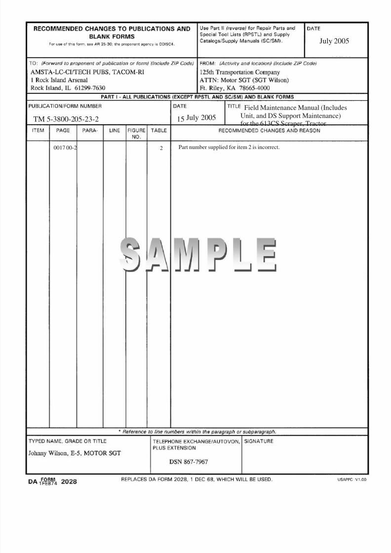
8/14/2019 TM 5-3800-205-23-2 MODEL 613CS
http://slidepdf.com/reader/full/tm-5-3800-205-23-2-model-613cs 265/276
0017 00-2 2 Part number supplied for item 2 is incorrect.
July 2005
TM 5-3800-205-23-2 15 July 2005
Field Maintenance Manual (Includes
Unit, and DS Support Maintenance)for the 613CS Scraper, Tractor

8/14/2019 TM 5-3800-205-23-2 MODEL 613CS
http://slidepdf.com/reader/full/tm-5-3800-205-23-2-model-613cs 266/276

8/14/2019 TM 5-3800-205-23-2 MODEL 613CS
http://slidepdf.com/reader/full/tm-5-3800-205-23-2-model-613cs 267/276
TM 5-3800-205-23-2 15 July 2005
Field Maintenance Manual (IncludesUnit, and DS Support Maintenance)for the 613CS Scraper, Tractor
8/14/2019 TM 5-3800-205-23-2 MODEL 613CS
http://slidepdf.com/reader/full/tm-5-3800-205-23-2-model-613cs 268/276

8/14/2019 TM 5-3800-205-23-2 MODEL 613CS
http://slidepdf.com/reader/full/tm-5-3800-205-23-2-model-613cs 269/276
TM 5-3800-205-23-2 15 July 2005
Field Maintenance Manual (IncludesUnit, and DS Support Maintenance)for the 613CS Scraper, Tractor

8/14/2019 TM 5-3800-205-23-2 MODEL 613CS
http://slidepdf.com/reader/full/tm-5-3800-205-23-2-model-613cs 270/276
8/14/2019 TM 5-3800-205-23-2 MODEL 613CS
http://slidepdf.com/reader/full/tm-5-3800-205-23-2-model-613cs 271/276
TM 5-3800-205-23-2 15 July 2005
Field Maintenance Manual (IncludesUnit, and DS Support Maintenance)for the 613CS Scraper, Tractor

8/14/2019 TM 5-3800-205-23-2 MODEL 613CS
http://slidepdf.com/reader/full/tm-5-3800-205-23-2-model-613cs 272/276

8/14/2019 TM 5-3800-205-23-2 MODEL 613CS
http://slidepdf.com/reader/full/tm-5-3800-205-23-2-model-613cs 273/276

8/14/2019 TM 5-3800-205-23-2 MODEL 613CS
http://slidepdf.com/reader/full/tm-5-3800-205-23-2-model-613cs 274/276
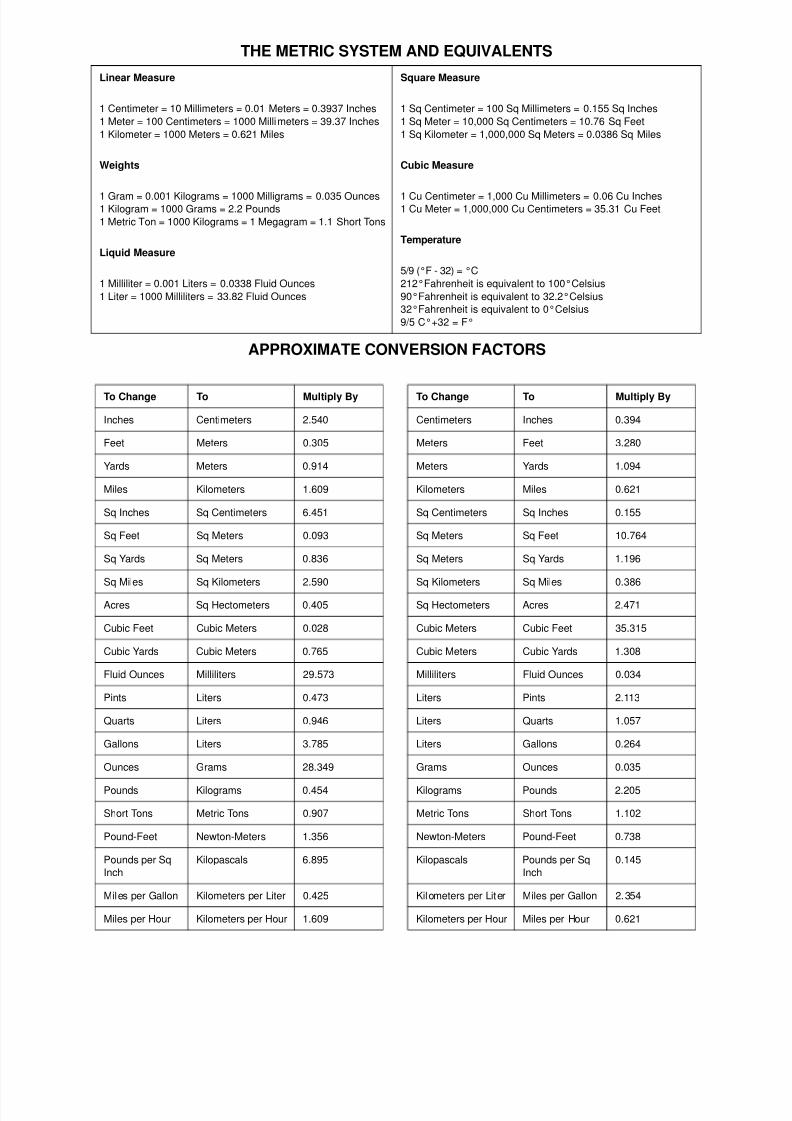
8/14/2019 TM 5-3800-205-23-2 MODEL 613CS
http://slidepdf.com/reader/full/tm-5-3800-205-23-2-model-613cs 275/276
THE METRIC SYSTEM AND EQUIVALENTS
APPROXIMATE CONVERSION FACTORS
Linear Measure
1 Centimeter = 10 Millimeters = 0.01 Meters = 0.3937 Inches
1 Meter = 100 Centimeters = 1000 Millimeters = 39.37 Inches
1 Kilometer = 1000 Meters = 0.621 Miles
Weights
1 Gram = 0.001 Kilograms = 1000 Milligrams = 0.035 Ounces1 Kilogram = 1000 Grams = 2.2 Pounds
1 Metric Ton = 1000 Kilograms = 1 Megagram = 1.1 Short Tons
Liquid Measure
1 Milliliter = 0.001 Liters = 0.0338 Fluid Ounces
1 Liter = 1000 Milliliters = 33.82 Fluid Ounces
Square Measure
1 Sq Centimeter = 100 Sq Millimeters = 0.155 Sq Inches
1 Sq Meter = 10,000 Sq Centimeters = 10.76 Sq Feet
1 Sq Kilometer = 1,000,000 Sq Meters = 0.0386 Sq Miles
Cubic Measure
1 Cu Centimeter = 1,000 Cu Millimeters = 0.06 Cu Inches1 Cu Meter = 1,000,000 Cu Centimeters = 35.31 Cu Feet
Temperature
5/9 (°F - 32) = °C
212°Fahrenheit is equivalent to 100°Celsius
90°Fahrenheit is equivalent to 32.2°Celsius
32°Fahrenheit is equivalent to 0°Celsius
9/5 C°+32 = F°
To Change To Multiply By
Inches Centimeters 2.540
Feet Meters 0.305
Yards Meters 0.914
Miles Kilometers 1.609
Sq Inches Sq Centimeters 6.451
Sq Feet Sq Meters 0.093
Sq Yards Sq Meters 0.836
Sq Miles Sq Kilometers 2.590
Acres Sq Hectometers 0.405
Cubic Feet Cubic Meters 0.028
Cubic Yards Cubic Meters 0.765
Fluid Ounces Milliliters 29.573
Pints Liters 0.473
Quarts Liters 0.946
Gallons Liters 3.785
Ounces Grams 28.349
Pounds Kilograms 0.454
Short Tons Metric Tons 0.907
Pound-Feet Newton-Meters 1.356
Pounds per Sq
Inch
Kilopascals 6.895
Miles per Gallon Kilometers per Liter 0.425
Miles per Hour Kilometers per Hour 1.609
To Change To Multiply By
Centimeters Inches 0.394
Meters Feet 3.280
Meters Yards 1.094
Kilometers Miles 0.621
Sq Centimeters Sq Inches 0.155
Sq Meters Sq Feet 10.764
Sq Meters Sq Yards 1.196
Sq Kilometers Sq Miles 0.386
Sq Hectometers Acres 2.471
Cubic Meters Cubic Feet 35.315
Cubic Meters Cubic Yards 1.308
Milliliters Fluid Ounces 0.034
Liters Pints 2.113
Liters Quarts 1.057
Liters Gallons 0.264
Grams Ounces 0.035
Kilograms Pounds 2.205
Metric Tons Short Tons 1.102
Newton-Meters Pound-Feet 0.738
Kilopascals Pounds per Sq
Inch
0.145
Kilometers per Liter Miles per Gallon 2.354
Kilometers per Hour Miles per Hour 0.621

8/14/2019 TM 5-3800-205-23-2 MODEL 613CS
http://slidepdf.com/reader/full/tm-5-3800-205-23-2-model-613cs 276/276