Embed Size (px)
Citation preview
TM 5-4310-339-15
D E P A R T M E N T O F T H E A R M Y T E C H N I C A L M A N U A L
O P E R A T O R , O R G A N I Z A T I O N A L , D I R E C T A N D G E N E R A L S U P P O R T
A N D D E P O T M A I N T E N A N C E M A N U A L
C O M P R E S S O R , R E C I P R O C A T I N G , A I R ;
1 5 C F M , 1 7 5 P S I ;
E L E C T R I C M O T O R D R I V E N
( I N G E R S O L L - R A N D M O D E L 2 4 2 D 7 - ½ )
F S N 4 3 1 0 - 1 4 3 - 9 2 8 0
H E A D Q U A R T E R S , D E P A R T M E N T O F T H E A R M Y
D E C E M B E R 1 9 6 9


TM 5-4310-339-15C1
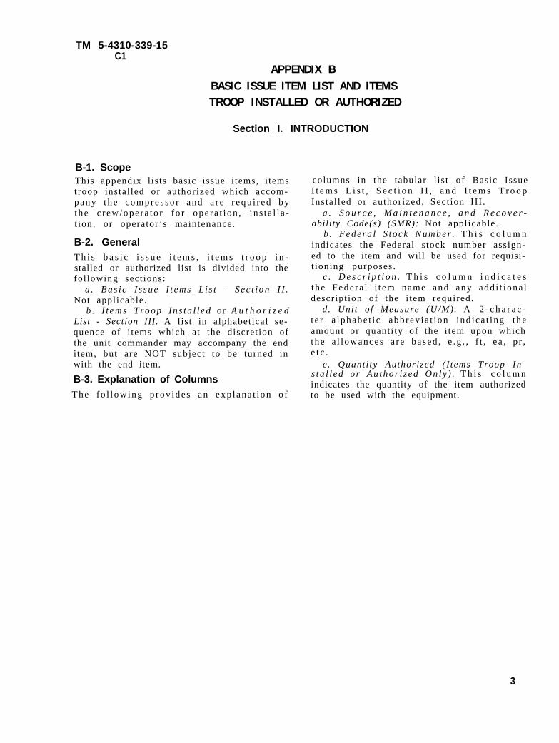
APPENDIX BBASIC ISSUE ITEM LIST AND ITEMSTROOP INSTALLED OR AUTHORIZED
Section I. INTRODUCTION
B-1. ScopeThis appendix l is ts basic issue i tems, i temstroop instal led or authorized which accom-p a n y t h e c o m p r e s s o r a n d a r e r e q u i r e d b ythe c r ew/ope ra to r fo r ope ra t i on , i n s t a l l a -t ion, or operator’s maintenance.
B-2. GeneralT h i s b a s i c i s s u e i t e m s , i t e m s t r o o p i n -stalled or authorized list is divided into thefol lowing sect ions:
a . Bas i c I s sue I t ems L i s t - Sec t i on I I .Not applicable.
b . I t e m s T r o o p I n s t a l l e d or A u t h o r i z e dList - Section III. A list in alphabetical se-quence of i tems which at the discret ion ofthe unit commander may accompany the enditem, but are NOT subject to be turned inwith the end item.
B-3. Explanation of ColumnsT h e f o l l o w i n g p r o v i d e s a n e x p l a n a t i o n o f
columns in the tabular l is t of Basic IssueI t e m s L i s t , S e c t i o n I I , a n d I t e m s T r o o pInstal led or authorized, Sect ion III .
a . S o u r c e , M a i n t e n a n c e , a n d R e c o v e r -ability Code(s) (SMR): Not applicable.
b . Federa l S tock Number . T h i s c o l u m nindicates the Federal s tock number assign-ed to the item and will be used for requisi-t ioning purposes .
c . D e s c r i p t i o n . T h i s c o l u m n i n d i c a t e sthe Fede ra l i t em name and any add i t i ona ldescr ipt ion of the i tem required.
d. Unit of Measure (U/M). A 2 - c h a r a c -t e r a lphabe t i c abb rev i a t i on i nd i ca t i ng t heamount or quant i ty of the i tem upon whichthe a l l owances a r e based , e .g . , f t , e a , p r ,e t c .
e. Quanti ty Authorized (I tems Troop In-s ta l l ed o r Au thor i z ed On ly ) . T h i s c o l u m nindicates the quantity of the item authorizedto be used with the equipment.
3

TM 5-4310-339-15C 1
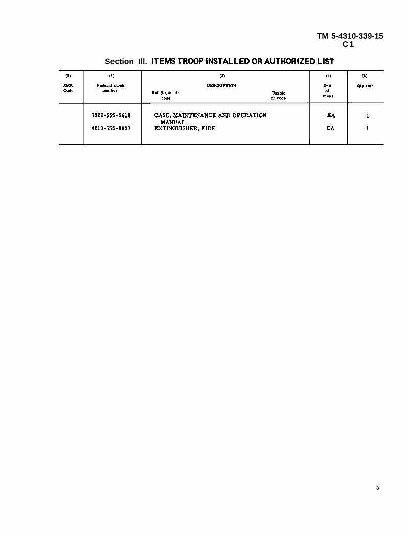
Section Ill. ITEMS TROOP INSTALLED OR AUTHORIZED LIST
(1)
SMRCode
(2)
Federal stocknumber
7520-559-9618
4210-555-8837
(3)
DESCRIPTION
Ref No. & mfr Usablecode on cede
CASE, MAINTENANCE AND OPERATIONMANUAL
EXTINGUISHER, FIRE
(4)
Unitof
mess.
EA
EA
I
(5)
Qty aUih
1
1
5
By Order of the Secretary of the Army:
Official:
CREIGHTON W. ABRAMS,General, United States Army,Chief of Staff.
VERNE L. BOWERS,Major General, United States Army,The Adjutant General.
Distribution:
To be distributed in accordance with DA Form 12-25A (qty rqr block no. 18), Organizational maintenance require-ments for Air Compressors 15 CFM.
U.S. GOVERNMENT PRINTING OFFICE: 1973-768109/267
TECHNICAL MANUAL
TM 5-4310-339-15
HEADQUARTERS
DEPARTMENT OF THE ARMY
NO. 5-4310-339-15 WASHINGTON, D.C.,29 December 1969
OPERATOR, ORGANIZATIONAL, DIRECT AND GENERAL SUPPORT AND DEPOT MAINTE-
NANCE MANUAL
COMPRESSOR, RECIPROCATING, AIR: 15 CFM, 175 PSI;
ELECTRIC MOTOR DRIVEN,
(INGERSOLL-RAND MoDEL 242D7-½)
FSN 4310-143-9280
Paragraph
SECTION I. GENERAL INFORMATION . . . . . . . . . . . . . . . .
Introduction . . . . . . . . . . . . . . ..1-1
General Data . . . . . . . . . . . . . . . . . 1-2
Associated Components . . . . . . . . . . . . .1-3
Weights . . . . . . . . . . . . . . . . . . . . ...1-4
Overall Dimensions . . . . . . . . . . . . . . 1-5
Description of Components . . . . . . . . . . .1-6
Compressor Regulation . . . . . . . . . . . . 1-24
Automatic Start and Stop Control . . . .1-25
II. INSTALLATION . . . . . . . . . . .. . . . . . . .
Power Requirements . . . . . . . . . .. . . . . . .2-1
Location and Ventilation . . . . . . . . . ...2-2
Foundation . . . . . . . . . . . . . . . . . . . 2-3
Page
1-1
1-1
1-1
1-2
1 -2
1-2
1-2
1-6
1-6
2-1
2-1
2-1
2-1
i
Paragraph
SECTION II.(CONTINUED) Belt Guard . . . . . . . . . . . . . . . . . . . . . . 2-4
Clearances for Access . . . . . . . . . . . . . . .2-5
Mechanical Assembly Procedures . . . . . .2-6
Testing for SatisfactoryInstallation . . . . . . . . . . . . . . . . . . .2-7
III. OPERATION. . . . . . . . . . . . . . . . . . . . . . . .
Pre-Starting Checks - New Units . . . . .3-1
Operating Checks . . . . . . . . . . . . . . . .3-2
Safety Precautions . . . . . . . . . . . . . .3-3
Starting . . . . . . . . . . . . . . . . . . . . . . .3-4
Stopping . . . . . . . . . . . . . . . . . . . . . . .3-5
Operator’s Maintenance . . . . . . . . . . . .3-6
IV. TROUBLESHOOTING . . . . . . . . . . . . . . . .
General . . . . . . . . . . . . . . . . . . . . . . . . .4-1
V. MAINTENANCE AND REPAIR . .. . . . . . . . . .
General . . . . . . . . . . . . . . . . . . . . . . . .5-1
Torque Values . . . . . . . . . . . . . . . . . . . .5-2
Compressor Lubrication . . . . . . . . . . . . . .5-3
Periodic Inspection and Mainte-nance . . . . . . . . . . . . . . . . . . . . . 5-4
Drive Belts . . . . . . . . . . . . . . . . . . . . . . . . .5-5
Air Valve Cleaning . . . . . . . . . . . . . . . . . .5-6
Piston Ring Replacement . . . . . . . . . . . . .5-7
Separating the Piston from theRod. . . . . . . . . . . . . . . . . . . . . . . . . . . 5-8
Page
2-2
2-2
2-2
2-2
3-1
3-1
3-1
3-1
3-2
3-2
3-2
4-1
4-1
5-1
5-1
5-1
5-1
5-2
5-2
5-4
5-4
5-8
ii
Paragraph
SECTION V. (CONTINUED) Crankshaft Assembly Replace-
ment . . . . . . . . . . . . . . . . . . . . . . .. 5-9
Oil Seal Replacement . . . . . . . . . . . . . .5-10
Pressure Switch Adjustment . . . . . . . .5-11
Pilot Valve Adjustment . . . . . . . . . . . .5-12
Check Valve Repair . . . . . . . . . . . . . ...5-13
Precautions for Extended Shutdown. . .5-l4
VI. MISCELLANEOUS DATA. . . . . . . . . . . . . . . .
General ELectric Motor Data -GEJ-2464D. . . . . . . . . . . . . . . .
General Electric Starter ControlData - GEH-2402F. . . . . . . . . . . . .
Square D Pressure Switch Data -L-4143. . . . . . . . . .. . . . . . . . . . . . . . . . . . . .
Kunkle Valve Data - CS-206 . . . . . . . . . .
APPENDIX A. MAINTENANCE ALLOCATION CHART . . . . . . . .
B. BASIC ISSUE ITEMS LIST . . . . . . . . . . . . . .
Page
5-8
5-9
5-9
5-10
5-10
5-11
6-1
6-3
6-5
6-9
6-11
A-1
B-1
iii

Section I
SECTION I
GENERAL INFORMATION
1-1. INTRODUCTION. This manual covers the installation, operation and maintenance ofthe Model 242 D7-1/2 Air Compressor.
The instructions contained herein are for the guidance of personnelresponsible for the operation and maintenance of the equipment.
1-2. GENERAL DATA.
Manufacturer’s Name . . . . . . . . . . . . . . . . . . . . . . . . . . . Ingersoll-Rand Company
Manufacturer's Model No. . . . . . . . . . . . . . . . . . . . . . . . . . . . . . . . . .242D7-1/2
Manufacturer’s Serial No. . . . . . . . . . . . . X30T275953 through X30T276025 inclusive
Capacity, CFM(cubic feet per minute). . . . . . . . . . . . . . . . . . . . . . . . . . . . . . .15
Pressure, PSIG (pounds per square inch gauge) . . . . . . . . . . . . . . . . . . . . . . 175
Speed of Shaft, RPM (revolutions per minute) . . . . . . . . . . . . . . . . . . . . . . . . .1040
Motor Horsepower . . . . . . . . . . . . . . . . . . . . . . . . . . . . . . . . . . . . . . . . . . . .7.5
Working Pressure, PSIG
First Stage . . . . . . . . . . . . . . . . . . . . . . . . . . . . . . . . . . . . . . . . . .35-40
Second Stage . . . . . . . . . . . . . . . . . . . . . . . . . . . . . . . . . . . . . . . . . .195
Safety Valve Pressure Setting, PSIG
First Stage . . . . . . . . . . . . . . . . . . . . . . . . . . . . . . . . . . . . . . . . .60
Second Stage . . . . . . . . . . . . . . . . . . . . . . . . . . . . . . . . . . . . . . . . . .200
Contract No . . . . . . . . . . . . . . . . . . . . . . . . . . . . . . . . . . . . . .DAAK-69-C-1735
Federal Stock No . . . . . . . . . . . . . . . . . . . . . . . . . . . . . . . . . . . .4310-143-9280
Maintenance Forms and Records. . . . . . . . Maintenance forms, records, and reportswhich are to be used by maintenance personnel at all levels are listed in andprescribed by TM 38-750.
1-1
Section I
1-3. ASSOCIATED COMPONENTS. Refer to Section VI for the details of the followingcomponents:
Drivcr . . . . . . . . . . . . . . . . . . . . . . . . . . . . . . . . . . . . . . . . . . General Electric
Controller . . . . . . . . . . . . . . . . . . . . . . . . . . . . . . . . . . . . . . . . General Electric
Air Pressure Switch . . . . . . . . . . . . . . . . . . . . . . . . . . . . . Square D
First Stage Safety Valve. . . . . . . . . . . . . . . . . . . . . . . . . . . . . . . .KunkleValve
Second Stage Safety Valve... . . . . . . . . . . . . . . . . . . . . . . .Kunkle Valve
1-4. WEIGHTS.
Controller, Lb (Pound) . . . . . . . . . . . . . . . . . . . . . . . . . . . . . . . . . . . . . . . . . .6
Recievcr, Lb . . . . . . . . . . . . . . . . . . . . . . . . . . . . . . . . . . . . . . . . . . . . . . .360
Motor, Lb . . . . . . . . . . . . . . . . . . . . . . . . . . . . . . . . . . . . . . . . . . . . . . . . .127
Compressor -Dry, Lb....... . . . . . . . . . . . . . . . . . . . . . . . . . . . . . . . . .170
1-5. OVERALL DIMENSIONS.
Width, In. (Inches) . . . . . . . . . . . . . . . . . . . . . . . . . . . . . . . . . . . . . . . ...24.5
Height. In . . . . . . . . . . . . . . . . . . . . . . . . . . . . . . . . . . . . . . . . . . . . . ...41.0
Length, In . . . . . . . . . . . . . . . . . . . . . . . . . . . . . . . . . . . . . . . . . . . . . ...63.0
1-6. DESCRIPTION OF COMPONETS
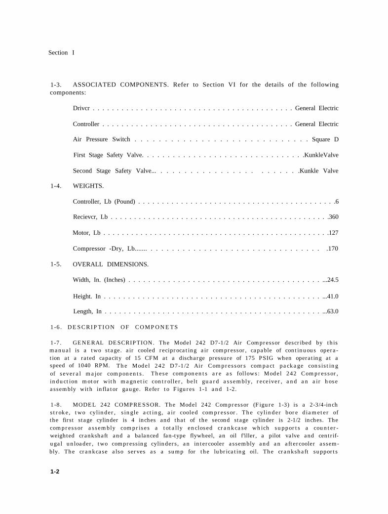
1-7. GENERAL DESCRIPTION. The Model 242 D7-1/2 Air Compressor described by thismanual is a two stage. air cooled reciprocating air compressor, capable of continuous opera-tion at a rated capacity of 15 CFM at a discharge pressure of 175 PSIG when operating at aspeed of 1040 RPM. The Model 242 D7-1/2 Air Compressors compact package consistingof several major components. These components are as follows: Model 242 Compressor,induction motor with magnetic controller, belt guard assembly, receiver, and an air hoseassembly with inflator gauge. Refer to Figures 1-1 and 1-2.
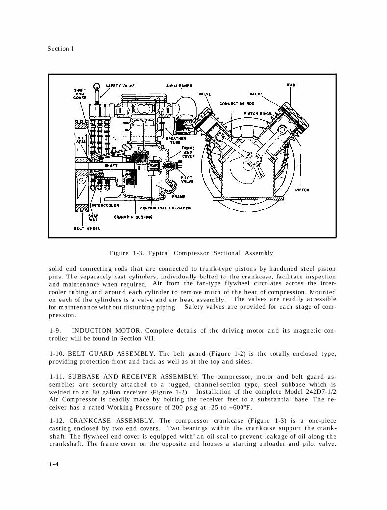
1-8. MODEL 242 COMPRESSOR. The Model 242 Compressor (Figure 1-3) is a 2-3/4-inchstroke, two cylinder, single acting, air cooled compressor. The cylinder bore diameter ofthe first stage cylinder is 4 inches and that of the second stage cylinder is 2-1/2 inches. Thecompressor assembly comprises a totally enclosed crankcase which supports a counter-weighted crankshaft and a balanced fan-type flywheel, an oil f’iller, a pilot valve and centrif-ugal unloader, two compressing cylinders, an intercooler assembly and an aftercooler assem-bly. The crankcase also serves as a sump for the lubricating oil. The crankshaft supports
1-2
Section I
Figure 1-1. Model 242D7-1-1/2 Compressor, Front View
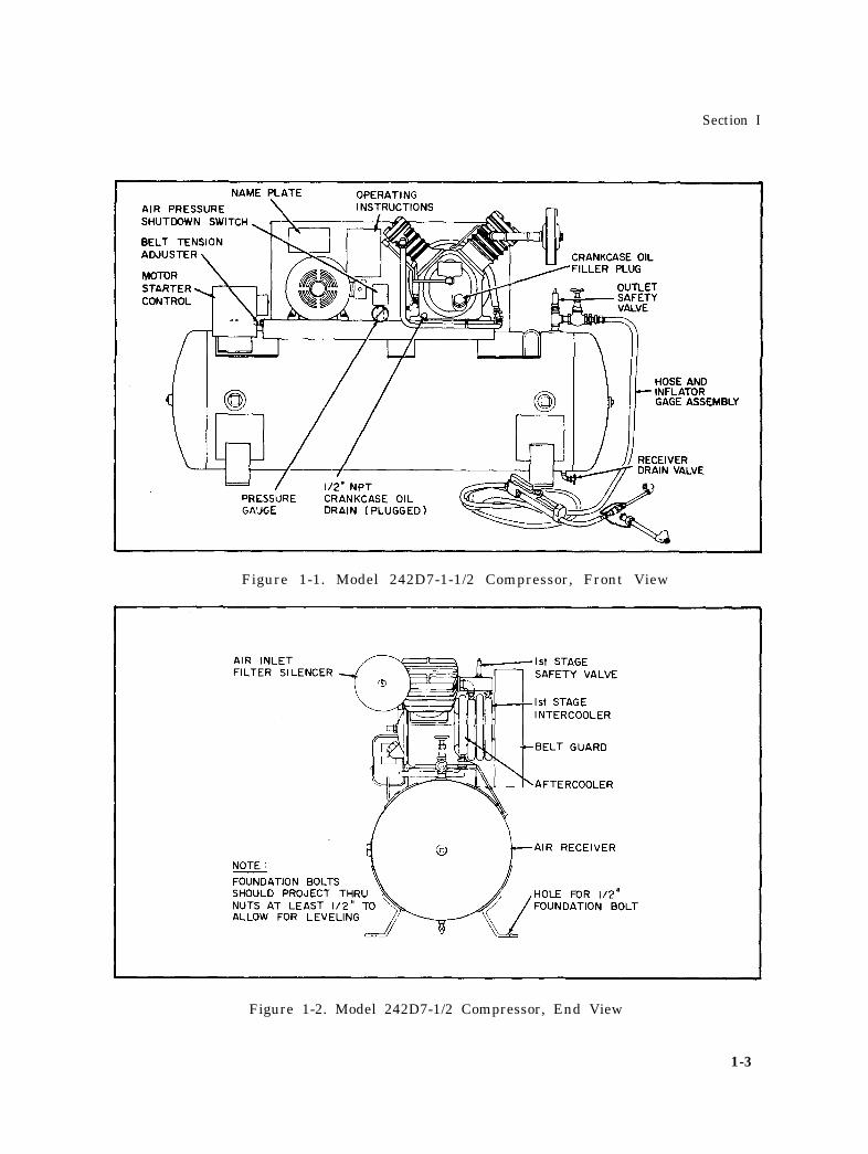
Figure 1-2. Model 242D7-1/2 Compressor, End View
1-3
Section I
Figure 1-3. Typical Compressor Sectional Assembly
solid end connecting rods that are connected to trunk-type pistons by hardened steel pistonpins. The separately cast cylinders, individually bolted to the crankcase, facilitate inspectionand maintenance when required. Air from the fan-type flywheel circulates across the inter-cooler tubing and around each cylinder to remove much of the heat of compression. Mountedon each of the cylinders is a valve and air head assembly. The valves are readily accessiblefor maintenance without disturbing piping. Safety valves are provided for each stage of com-pression.
1-9. INDUCTION MOTOR. Complete details of the driving motor and its magnetic con-troller will be found in Section VII.
1-10. BELT GUARD ASSEMBLY. The belt guard (Figure 1-2) is the totally enclosed type,providing protection front and back as well as at the top and sides.
1-11. SUBBASE AND RECEIVER ASSEMBLY. The compressor, motor and belt guard as-semblies are securely attached to a rugged, channel-section type, steel subbase which iswelded to an 80 gallon receiver {Figure 1-2). Installation of the complete Model 242D7-1/2Air Compressor is readily made by bolting the receiver feet to a substantial base. The re-ceiver has a rated Working Pressure of 200 psig at -25 to +600°F.
1-12. CRANKCASE ASSEMBLY. The compressor crankcase (Figure 1-3) is a one-piececasting enclosed by two end covers. Two bearings within the crankcase support the crank-shaft. The flywheel end cover is equipped with’ an oil seal to prevent leakage of oil along thecrankshaft. The frame cover on the opposite end houses a starting unloader and pilot valve.
1-4
Section I
1-13. CRANKSHAFT AND CONNECTING RODS. The crankshaft has an overhung crank-throw which permits the use of solid end-type connecting rods (Figure 1-3). The crankshaftis counterweighted to give proper running balance. The drive end is keyed to receive thefan-type flywheel. The other end of the crankshaft is fitted with a crankpin cap on which ismounted the centrifugal starting unloader. Each of the connecting rods is cast in one piece,and both are readily replaceable. A single crankpin bushing serves as a bearing for thecrankshaft end of both connecting rods. A pressed-in solid bronze bushing is located in thepiston end of both connecting rods. Oil dippers are cast as integral parts of both connectingrods and provide splash lubrication to all running parts. The one-piece construction of theconnecting rods assures proper alignment.
1-14. BREATHER TUBE. A breather tube (Figure 1-3) connects the interior of the crank-case to the inboard side of the air inlet filter silencer. This connection permits pulsationscreated by the reciprocating action of the pistons to be vented to atmosphere, thus preventingany pressure build-up within the crankcase.
1-15. FAN-TYPE FLYWHEEL. The fan-type flywheel (Figure 1-3) is keyed to the com-pressor crankshaft and is enclosed by the belt guard assembly. It moves ambient air throughthe belt guard, drawing it over the aftercoole r and intercooler tubing and discharging it aroundthe cylinders, providing the required cooling for the compressor.
1-16. CYLINDERS AND PISTON ASSEMBLIES. The compressor has two cast iron cylinders(Figure 1-3), one for each stage. Each cylinder is a one-piece casting with integral coolingfins and is bolted to the crankcase with a gasket between the two. Each cylinder bore ishoned to provide a proper wearing and sealing surface for the piston rings. Each piston isequipped with two single piece, taper-faced style compression rings; one four-piece, venti-lated, chrome plated steel rail style oil control wiper ring; and one single-piece, non-ventilated beveled-scraper style oil control wiper ring. Piston pins are hardened steel with aground finish. They are full floating, with snap rings to prevent them from striking the cyl-inder walls. Both pistons are the trunk type, and made of aluminum.
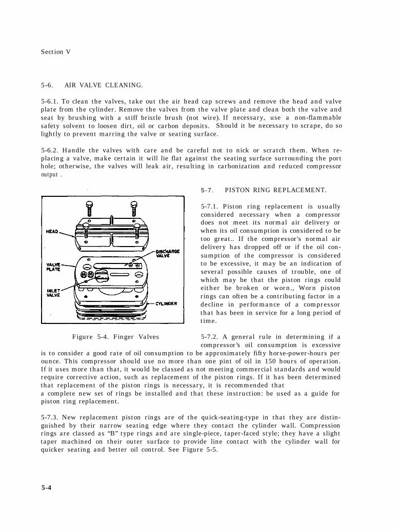
1-17. AIR HEADS AND VALVES. Air enters and leaves each cylinder through an air headand valve (Figure 1-3) at the top of the cylinder. The valves are stainless steel fingertype (Figure 5-4), consisting of valve spacer plates and inlet and discharge valves secured tothe plates with fillister head screws and nuts. The valve and spacer assemblies are securedto the cylinders by bolts through the air heads, with appropriate gaskets. They are readilyaccessible and may be removed without disturbing piping.
1-18. AIR INLET FILTER SILENCER. An air inlet filter silencer (Figure 1-2) located atthe first stage cylinder inlet filters all air entering the compressor and reduces the noiselevel of the intake pulsations to a level which is not objectionable. The filter uses cleanablepads to remove harmful grit and dirt from the intake air. If the air in the vicinity of the com-pressor is unduly dirty or contains corrosive fumes, pipe the filter silencer to a source ofcleaner air.
1-19. STARTING UNLOADER. The compressor is equipped with a starting unloader1-3) which relieves cylinder pressure when the compressor stops, permitting it
(Figureto start
1-5
Section I
against a light load. This increases the life of the drive motor and belts and also reduces thepossibility of tripping the motor overload relay. The unloader incorporates a pilot valvewhich is actuated centrifugally by unloader weights attached to the end of the crankshaft.
1-20. INTERCOOLER AND AFTERCOOLER. The compressor is equipped with an inter-cooler (Figure 1-2) between the first and second stages which removes most of the heat ofcompression from the air before it enters the second stage, thus improving efficiency anddecreasing the final discharge air temperature. The intercooler consists of finned tubingconnecting the discharge of the first stage to the inlet of the second. The compressed airflows through these tubes and its heat is transferred to the cooling fins. The ambient airfrom the fan-type flywheel passes over the fins, dissipating the heat to atmosphere. Theaftercooler (Figure 1-2) consists of finned tubing connecting the second stage discharge to thereceiver, and functions in the same manner as the intercooler.
1-21. SAFETY VALVES. Safety valves are provided for both the first and second stages toprotect against damage from over pressure. The first stage safety valve (Figure 1-2) ismounted on the intercooler outlet manifold, and the second stage safety valve (Figure l-l) islocated in the service line of the receiver. The first stage safety valve is set to blow at 60PSIG, and the second stage is set at 200 PSIG.
1-22. STARTING SWITCH. The compressor starting switch is incorporated as a part of themagnetic controller (Figure 1-1) furnished with the driving motor. The controller incorpo-rates an ON-OFF snapswitch for starting and stopping the compressor. Complete detailswill be found in Section VI..
1-23. CHECK VALVE. A check valve (Figure 5-13) is located in the discharge line and actsto check the flow of air from the air receiver to the cylinder when the compressor is stopped.
1-24. COMPRESSOR REGULATION. The compressor is regulated by Automatic Start andStop Control, which makes or breaks electrical contact to the motor at predetermined pres-s u r e s . This type of regulation is used when the demand for air is small or intermittent, butwhere pressure must be continuously maintained.
1-25. AUTOMATIC START AND STOP CONTROL .
1-25.1. Automatic Start and Stop Control is obtained by means of a pressure switch (Figurel-l) which makes and breaks an electrical circuit, starting and stopping the driving motor,thereby maintaining the air receiver pressure within prescribed limits. The pressure switchis piped to the receiver and is actuated by changes in receiver pressure.
1-25.2. The pressure switch has a cut-out adjustment and a differential adjustment. Thecut-out is the pressure at which the switch contacts open, and the differential is the span be-tween the cut-in and cut-out settings. A fairly wide differential setting of the pressure switchshould be maintained to prevent frequent starting and stopping of the compressor.
1-6
Section II
SECTION II
INSTALLATION
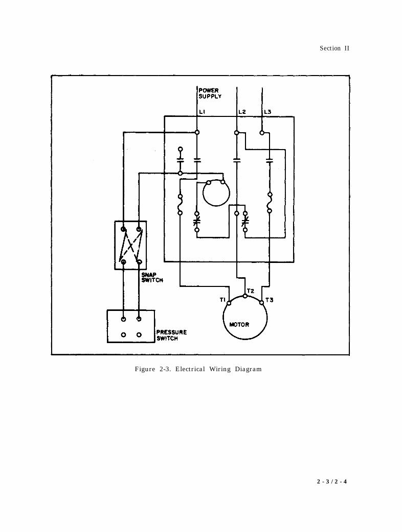
2-1. POWER REQUIREMENTS. The driving motor requires a 220 volt, 3 phase, 60 hertzelectrical source. Connections to be made between the electrical supply system and the com-pressor are shown in Figure 2-3.
2-2. LOCATION AND VENTILATION. In cold climates, it is desirable to install the com-pressor in a heated building. Choose a clean, relatively cool location. and provide amplespace around the unit for cooling and general accessibility. Adequate ventilation must beprovided the compressor to assure proper intercooling and aftercooling as well as heat dissi-pation from the cylinders. This is especially important under conditions of high humidity,which are conducive to formation of water in the crankcase. If adequate ventilation is notprovided. rusting, oil sludging and rapid wear of running parts may result. This is particu-larly true for compressors operating on very intermittent duty. At least 15 inches of spaceshould be provided between the aftercooler end of the unit and the nearest wall.
2-3. FOUNDATION.
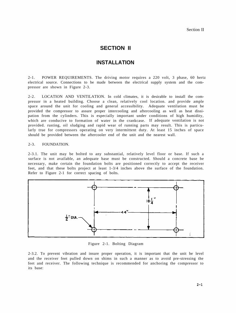
2-3.1. The unit may be bolted to any substantial, relatively level floor or base. If such asurface is not available, an adequate base must be constructed. Should a concrete base benecessary, make certain the foundation bolts are positioned correctly to accept the receiverfeet, and that these bolts project at least 1-3/4 inches above the surface of the foundation.Refer to Figure 2-1 for correct spacing of bolts.
Figure 2-1. Bolting Diagram
2-3.2. To prevent vibration and insure proper operation, it is important that the unit be leveland the receiver feet pulled down on shims in such a manner as to avoid pre-stressing thefeet and receiver. The following technique is recommended for anchoring the compressor toits base:
2-1
Section II
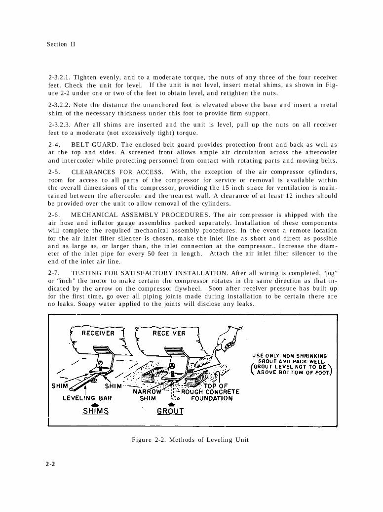
2-3.2.1. Tighten evenly, and to a moderate torque, the nuts of any three of the four receiverfeet. Check the unit for level. If the unit is not level, insert metal shims, as shown in Fig-ure 2-2 under one or two of the feet to obtain level, and retighten the nuts.
2-3.2.2. Note the distance the unanchored foot is elevated above the base and insert a metalshim of the necessary thickness under this foot to provide firm support.
2-3.2.3. After all shims are inserted and the unit is level, pull up the nuts on all receiverfeet to a moderate (not excessively tight) torque.
2-4. BELT GUARD. The enclosed belt guard provides protection front and back as well asat the top and sides. A screened front allows ample air circulation across the aftercoolerand intercooler while protecting personnel from contact with rotating parts and moving belts.
2-5. CLEARANCES FOR ACCESS. With, the exception of the air compressor cylinders,room for access to all parts of the compressor for service or removal is available withinthe overall dimensions of the compressor, providing the 15 inch space for ventilation is main-tained between the aftercooler and the nearest wall. A clearance of at least 12 inches shouldbe provided over the unit to allow removal of the cylinders.
2-6. MECHANICAL ASSEMBLY PROCEDURES. The air compressor is shipped with theair hose and inflator gauge assemblies packed separately. Installation of these componentswill complete the required mechanical assembly procedures. In the event a remote locationfor the air inlet filter silencer is chosen, make the inlet line as short and direct as possibleand as large as, or larger than, the inlet connection at the compressor.. Increase the diam-eter of the inlet pipe for every 50 feet in length. Attach the air inlet filter silencer to theend of the inlet air line.
2-7. TESTING FOR SATISFACTORY INSTALLATION. After all wiring is completed, “jog”or “inch” the motor to make certain the compressor rotates in the same direction as that in-dicated by the arrow on the compressor flywheel. Soon after receiver pressure has built upfor the first time, go over all piping joints made during installation to be certain there areno leaks. Soapy water applied to the joints will disclose any leaks.
Figure 2-2. Methods of Leveling Unit
2-2
Section II
Figure 2-3. Electrical Wiring Diagram
2 - 3 / 2 - 4

Section III
SECTION Ill
OPERATION
3-1. PRE -STARTING CHECKS - NEW UNITS.
3-1.1. Before starting a new unit fill the compressor crankcase to the overflow point withoil as specified in Table 5-2.
3-1.2. Turn the compressor flywheel through several revolutions by hand to see that every-thing is free and in working order.
3-1.3. Check the tension of the belts as described in Paragraph 5-5.
3-1.4. Remove tools, rags and any other objects from the vicinity of the compressor beforestarting it.
3-2. OPERATING CHECKS. Satisfactory operation depends to a large degree upon adher-ence to a preventative maintenance schedule. To obtain optimum performance, observe theRoutine Inspection and Maintenance Guide in Table 3-4. As a further initial precaution,tighten all capscrews and nuts after 25-to 50-hours to maintain efficiency and prevent loss ofoil. Tighten to the torque values recommended in Table 5-1.
3-3. SAFETY PRECAUTIONS. The following precautions should be observed to assure thesafety of operating personnel.
3-3.1. BEFORE OPERATION.
Be sure all guards are in place.
Remove all tools and other objects from the compress or.
3-3.2. DURING OPERATION.
Always stop the compressor before making adjustments.
Never disconnect any air lines without first relieving pressure from the entire unit.
Never direct air at personnel; serious injury may result.
3-3.3. AFTER OPERATION.
Drain the receiver and relieve all air pressure from the entire unit before performingany maintenance on the compressor.
3-1
Section III
TABLE 3-1. OPERATING CONTROLS (REF FIG. 1-1. )
Control Action
Motor Controller
On-Off Snapswitch Position as required
Reset Pushbutton Push to reset
Receiver Drain Valve Open to drain receiver
TABLE 3-2. INDICATING DEVICES (REF FIG. 1-1. )
Device Normal Operating Indication
Pressure Gauge
Receiver 175-to 200-PSIG
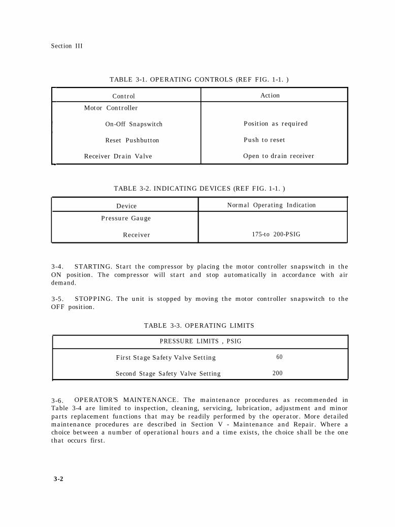
3-4. STARTING. Start the compressor by placing the motor controller snapswitch in theON position. The compressor will start and stop automatically in accordance with airdemand.
3-5. STOPPING. The unit is stopped by moving the motor controller snapswitch to theOFF position.
TABLE 3-3. OPERATING LIMITS
PRESSURE LIMITS , PSIG
First Stage Safety Valve Setting 60
Second Stage Safety Valve Setting 200
3-6. OPERATOR’S MAINTENANCE. The maintenance procedures as recommended inTable 3-4 are limited to inspection, cleaning, servicing, lubrication, adjustment and minorparts replacement functions that may be readily performed by the operator. More detailedmaintenance procedures are described in Section V - Maintenance and Repair. Where achoice between a number of operational hours and a time exists, the choice shall be the onethat occurs first.
3-2
Section III
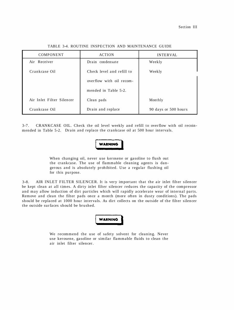
TABLE 3-4. ROUTINE INSPECTION AND MAINTENANCE GUIDE
COMPONENT
Air Receiver
Crankcase Oil
Air Inlet Filter Silencer
Crankcase Oil
ACTION
Drain condensate
Check level and refill to
overflow with oil recom-
mended in Table 5-2.
Clean pads
Drain and replace
INTERVAL
Weekly
Weekly
Monthly
90 days or 500 hours
3-7. CRANKCASE OIL. Check the oil level weekly and refill to overflow with oil recoin-mended in Table 5-2. Drain and replace the crankcase oil at 500 hour intervals.
When changing oil, never use kerosene or gasoline to flush outthe crankcase. The use of flammable cleaning agents is dan-gerous and is absolutely prohibited. Use a regular flushing oilfor this purpose.
3-8. AIR INLET FILTER SILENCER. It is very important that the air inlet filter silencerbe kept clean at all times. A dirty inlet filter silencer reduces the capacity of the compressorand may allow induction of dirt particles which will rapidly accelerate wear of internal parts.Remove and clean the filter pads once a month (more often in dusty conditions). The padsshould be replaced at 1000 hour intervals. As dirt collects on the outside of the filter silencerthe outside surfaces should be brushed.
We recommend the use of safety solvent for cleaning. Neveruse kerosene, gasoline or similar flammable fluids to clean theair inlet filter silencer.
Section III
3-9. INTERCOOLER AND AFTERCOOLER. Never permit air flow to the intercooler oraftercooler tubes to become obstructed, and clean the surface of the tubes whenever depositsof oil, dirt and grease are observed. Use a non-flammable safety solvent for cleaningpurposes.
3-10. SAFETY VALVES. The safety valves are provided to protect against damage fromoverpressure. If either valve blows, and continues to blow for more than a minute, the com-pressor should be stopped at once. Refer to Table 4-1, Compressor Troubleshooting Chart,to determine the cause of the blowing safety valve.
3-4
Section IV
SECTION IV
TROUBLESHOOTING
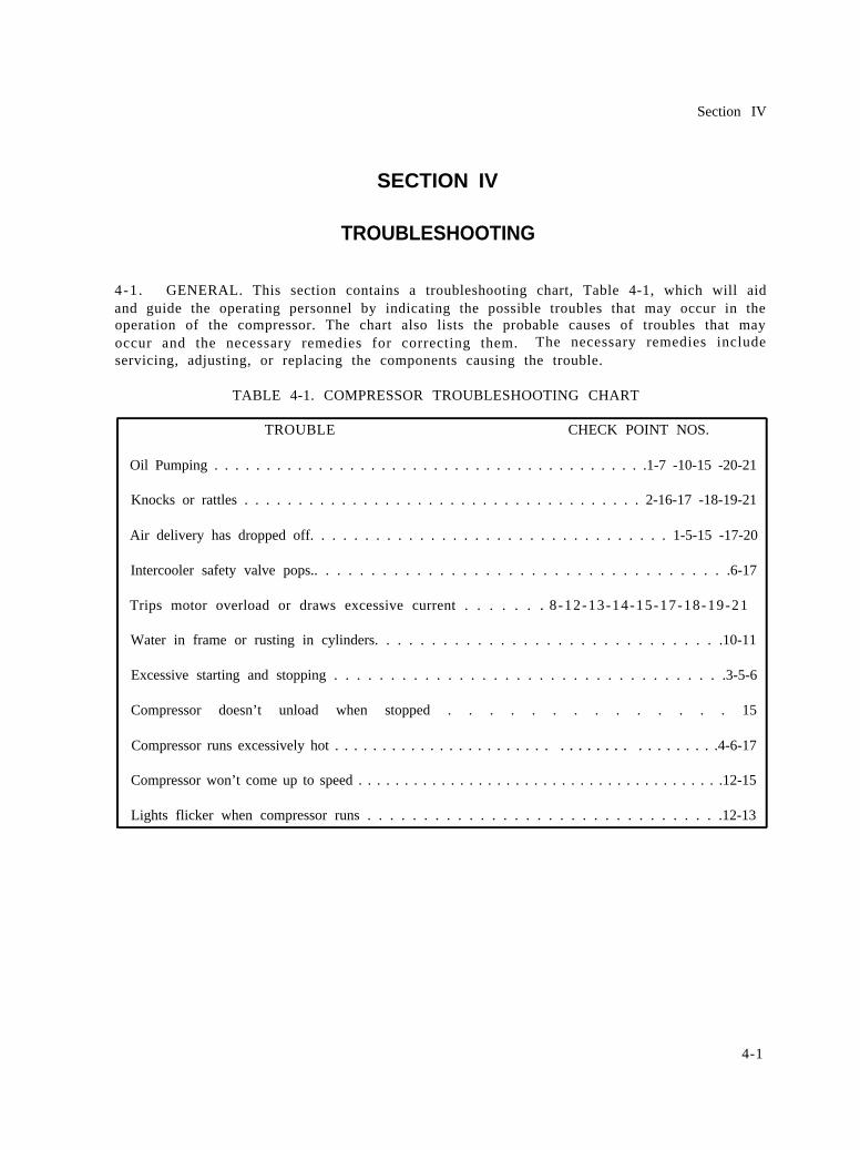
4-1 . GENERAL. This section contains a troubleshooting chart, Table 4-1, which will aidand guide the operating personnel by indicating the possible troubles that may occur in theoperation of the compressor. The chart also lists the probable causes of troubles that mayoccur and the necessary remedies for correcting them. The necessary remedies includeservicing, adjusting, or replacing the components causing the trouble.
TABLE 4-1. COMPRESSOR TROUBLESHOOTING CHART
TROUBLE CHECK POINT NOS.
Oil Pumping . . . . . . . . . . . . . . . . . . . . . . . . . . . . . . . . . . . . . . . . . .1-7 -10-15 -20-21
Knocks or rattles . . . . . . . . . . . . . . . . . . . . . . . . . . . . . . . . . . . . . 2-16-17 -18-19-21
Air delivery has dropped off. . . . . . . . . . . . . . . . . . . . . . . . . . . . . . . . . 1-5-15 -17-20
Intercooler safety valve pops.. . . . . . . . . . . . . . . . . . . . . . . . . . . . . . . . . . . . .6-17
Trips motor overload or draws excessive current . . . . . . . 8-12-13-14-15-17-18-19-21
Water in frame or rusting in cylinders. . . . . . . . . . . . . . . . . . . . . . . . . . . . . . .10-11
Excessive starting and stopping . . . . . . . . . . . . . . . . . . . . . . . . . . . . . . . . . . .3-5-6
Compressor doesn’t unload when stopped . . . . . . . . . . . . . . 15
Compressor runs excessively hot . . . . . . . . . . . . . . . . . . . . . . . . . . . . . . . . . . . . . . . .4-6-17
Compressor won’t come up to speed . . . . . . . . . . . . . . . . . . . . . . . . . . . . . . . . . . . . . . . .12-15
Lights flicker when compressor runs . . . . . . . . . . . . . . . . . . . . . . . . . . . . . . . .12-13
4-1
Section IV
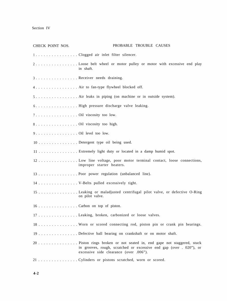
CHECK POINT NOS. PROBABLE TROUBLE CAUSES
1 . . . . . . . . . . . . . . . . Clogged air inlet filter silencer.
2 . . . . . . . . . . . . . . . . Loose belt wheel or motor pulley or motor with excessive end playin shaft.
3 . . . . . . . . . . . . . . . . Receiver needs draining.
4 . . . . . . . . . . . . . . . . Air to fan-type flywheel blocked off.
5 . . . . . . . . . . . . . . . . Air leaks in piping (on machine or in outside system).
6 . . . . . . . . . . . . . . . . High pressure discharge valve leaking.
7 . . . . . . . . . . . . . . . . Oil viscosity too low.
8 . . . . . . . . . . . . . . . . Oil viscosity too high.
9 . . . . . . . . . . . . . . . . Oil level too low.
10 . . . . . . . . . . . . . . . Detergent type oil being used.
11 . . . . . . . . . . . . . . . Extremely light duty or located in a damp humid spot.
12 . . . . . . . . . . . . . . . Low line voltage, poor motor terminal contact, loose connections,improper starter heaters.
13 . . . . . . . . . . . . . . . Poor power regulation (unbalanced line).
14 . . . . . . . . . . . . . . . V-Belts pulled excessively tight.
15 . . . . . . . . . . . . . . . Leaking or maladjusted centrifugalon pilot valve.
16 . . . . . . . . . . . . . . . Carbon on top of piston.
pilot valve, or defective O-Ring
17 . . . . . . . . . . . . . . . Leaking, broken, carbonized or loose valves.
18 . . . . . . . . . . . . . . . Worn or scored connecting rod, piston pin or crank pin bearings.
19 . . . . . . . . . . . . . . . Defective ball bearing on crankshaft or on motor shaft.
20 . . . . . . . . . . . . . . . Piston rings broken or not seated in, end gape not staggered, stuckin grooves, rough, scratched or excessive end gap (over . 020”), orexcessive side clearance (over .006”).
21 . . . . . . . . . . . . . . . Cylinders or pistons scratched, worn or scored.
4-2
Section IV
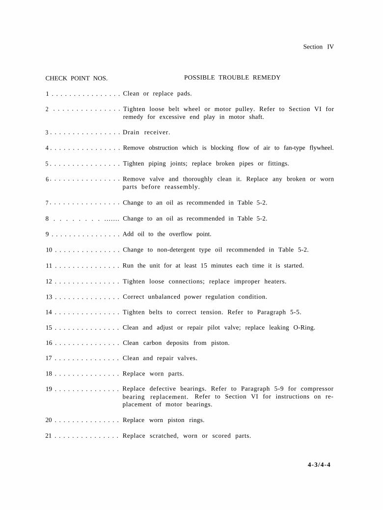
CHECK POINT NOS. POSSIBLE TROUBLE REMEDY
1 . . . . . . . . . . . . . . . . Clean or replace pads.
2 . . . . . . . . . . . . . . . Tighten loose belt wheel or motor pulley. Refer to Section VI forremedy for excessive end play in motor shaft.
3 . . . . . . . . . . . . . . . . Drain receiver.
4 . . . . . . . . . . . . . . . . Remove obstruction which is blocking flow of air to fan-type flywheel.
5 . . . . . . . . . . . . . . . . Tighten piping joints; replace broken pipes or fittings.
6 . . . . . . . . . . . . . . . . Remove valve and thoroughly clean it. Replace any broken or wornparts before reassembly.
7 . . . . . . . . . . . . . . . . Change to an oil as recommended in Table 5-2.
8 . . . . . . . . . . . . . . . Change to an oil as recommended in Table 5-2.
9 . . . . . . . . . . . . . . . . Add oil to the overflow point.
10 . . . . . . . . . . . . . . . Change to non-detergent type oil recommended in Table 5-2.
11 . . . . . . . . . . . . . . . Run the unit for at least 15 minutes each time it is started.
12 . . . . . . . . . . . . . . . Tighten loose connections; replace improper heaters.
13 . . . . . . . . . . . . . . . Correct unbalanced power regulation condition.
14 . . . . . . . . . . . . . . . Tighten belts to correct tension. Refer to Paragraph 5-5.
15 . . . . . . . . . . . . . . . Clean and adjust or repair pilot valve; replace leaking O-Ring.
16 . . . . . . . . . . . . . . .
17 . . . . . . . . . . . . . . .
18 . . . . . . . . . . . . . . .
19 . . . . . . . . . . . . . . .
20 . . . . . . . . . . . . . . .
21 . . . . . . . . . . . . . . .
Clean carbon deposits from piston.
Clean and repair valves.
Replace worn parts.
Replace defective bearings. Refer to Paragraph 5-9 for compressorbearing replacement. Refer to Section VI for instructions on re-placement of motor bearings.
Replace worn piston rings.
Replace scratched, worn or scored parts.
4-3/4-4

Section V
SECTION V
MAINTENANCE AND REPAIR
Before attempting any repair work on the unit. be certain thesnapswitch is in the OFF position or the wiring is disconnectedfrom the line. Blow down the pressure from the receiver andisolate the unit from any outside source of air pressure. Thesesimple precautions will prevent accidents.
5-1. GENERAL. This section provides information useful. to maintenancepersonnel in inspecting, servicing, repairing and otherwise maintainingthe air compressor. Any special disassembly or reassembly proceduresare described under the appropriate heading.
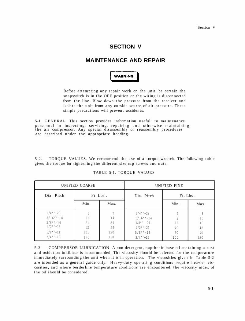
5-2. TORQUE VALUES. We recommend the use of a torque wrench. The following tablegives the torque for tightening the different size cap screws and nuts.
TABLE 5-1. TORQUE VALUES
UNIFIED COARSE UNIFIED FINE
Dia. Pitch Ft. Lbs . Dia. Pitch Ft. Lbs .
Min. Max. Min. Max.
1/4’’-20 6 7 1/4’’-28 5 65/16’’-18 12 14 5/16’’-24 9 103/8’’-16 21 24 3/8’’ -24 14 161/2’’-13 52 59 1/2’’-205/8’’-11
40 42105 120 5/8’’-l8 60 70
3/4’’-10 170 190 3/4’’-16 100 120
5-3. COMPRESSOR LUBRICATION. A non-detergent, napthenic base oil containing a rustand oxidation inhibitor is recommended. The viscosity should be selected for the temperatureimmediately surrounding the unit when it is in operation. The viscosities given in Table 5-2are intended as a general guide only. Heavy-duty operating conditions require heavier vis-cosities, and where borderline temperature conditions are encountered, the viscosity index ofthe oil should be considered.
5-1
Section V
TABLE 5-2. OIL VISCOSITY1
Viscosity at 100°F(37.8°C)
Temp. Range SSU Centistokes
40°F & Below (4.4°C & Below) 150 3240°F to 80°F (4.4°C to 26.7°C) 500 11080°F to 125°F (26.7°C to 51.7 C) 750 165
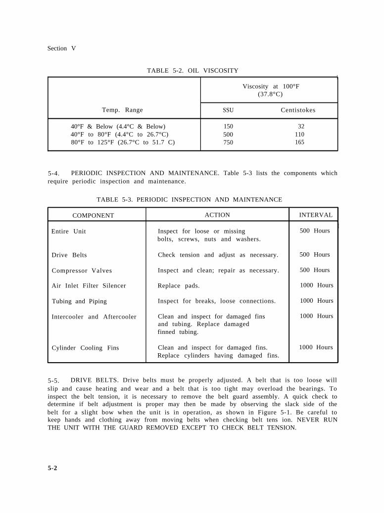
5-4. PERIODIC INSPECTION AND MAINTENANCE. Table 5-3 lists the components whichrequire periodic inspection and maintenance.
TABLE 5-3. PERIODIC INSPECTION AND MAINTENANCE
COMPONENT ACTION INTERVAL,I
Entire Unit Inspect for loose or missing 500 Hoursbolts, screws, nuts and washers.
Drive Belts Check tension and adjust as necessary. 500 Hours
Compressor Valves Inspect and clean; repair as necessary. 500 Hours
Air Inlet Filter Silencer Replace pads. 1000 Hours
Tubing and Piping Inspect for breaks, loose connections. 1000 Hours
Intercooler and Aftercooler Clean and inspect for damaged fins 1000 Hoursand tubing. Replace damagedfinned tubing.
Cylinder Cooling Fins Clean and inspect for damaged fins. 1000 HoursReplace cylinders having damaged fins.
5-5. DRIVE BELTS. Drive belts must be properly adjusted. A belt that is too loose willslip and cause heating and wear and a belt that is too tight may overload the bearings. Toinspect the belt tension, it is necessary to remove the belt guard assembly. A quick check todetermine if belt adjustment is proper may then be made by observing the slack side of thebelt for a slight bow when the unit is in operation, as shown in Figure 5-1. Be careful tokeep hands and clothing away from moving belts when checking belt tens ion. NEVER RUNTHE UNIT WITH THE GUARD REMOVED EXCEPT TO CHECK BELT TENSION.
5-2
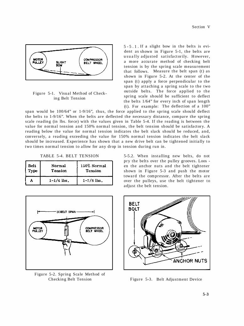
Figure 5-1. Visual Method of Check-ing Belt Tension
5 - 5 . 1 .dent asusually
Section V
If a slight bow in the belts is evi-shown in Figure 5-1, the belts areadjusted satisfactorily. However,
a more accurate method of checking belttension is by the spring scale measurementthat follows. Measure the belt span (t) asshown in Figure 5-2. At the center of thespan (t) apply a force perpendicular to thespan by attaching a spring scale to the twooutside belts. The force applied to thespring scale should be sufficient to deflectthe belts 1/64” for every inch of span length(t). For example: The deflection of a 100”
span would be 100/64” or 1-9/16”, thus, the force applied to the spring scale should deflectthe belts to 1-9/16”. When the belts are deflected the necessary distance, compare the springscale reading (in lbs. force) with the values given in Table 5-4. If the reading is between thevalue for normal tension and 150% normal tension, the belt tension should be satisfactory. Areading below the value for normal tension indicates the belt slack should be reduced, and,conversely, a reading exceeding the value for 150% normal tension indicates the belt slackshould be increased. Experience has shown that a new drive belt can be tightened initially totwo times normal tension to allow for any drop in tension during run in.
TABLE 5-4. BELT TENSION
Figure 5-2. Spring Scale Method ofChecking Belt Tension
5-5.2. When installing new belts, do notpry the belts over the pulley grooves. Loos -en the anchor nuts and the belt tightenershown in Figure 5-3 and push the motortoward the compressor. After the belts areover the pulleys, use the belt tightener toadjust the belt tension.
Figure 5-3. Belt Adjustment Device
5-3
Section V
5-6. AIR VALVE CLEANING.
5-6.1. To clean the valves, take out the air head cap screws and remove the head and valveplate from the cylinder. Remove the valves from the valve plate and clean both the valve andseat by brushing with a stiff bristle brush (not wire). If necessary, use a non-flammablesafety solvent to loosen dirt, oil or carbon deposits. Should it be necessary to scrape, do solightly to prevent marring the valve or seating surface.
5-6.2. Handle the valves with care and be careful not to nick or scratch them. When re-placing a valve, make certain it will lie flat against the seating surface surrounding the porthole; otherwise, the valves will leak air, resulting in carbonization and reduced compressoroutput .
5-7. PISTON RING REPLACEMENT.
Figure 5-4. Finger Valves
5-7.1. Piston ring replacement is usuallyconsidered necessary when a compressordoes not meet its normal air delivery orwhen its oil consumption is considered to betoo great.. If the compressor's normal airdelivery has dropped off or if the oil con-sumption of the compressor is consideredto be excessive, it may be an indication ofseveral possible causes of trouble, one ofwhich may be that the piston rings couldeither be broken or worn., Worn pistonrings can often be a contributing factor in adecline in performance of a compressorthat has been in service for a long period oftime.
5-7.2. A general rule in determining if acompressor’s oil consumption is excessive
is to consider a good rate of oil consumption to be approximately fifty horse-power-hours perounce. This compressor should use no more than one pint of oil in 150 hours of operation.If it uses more than that, it would be classed as not meeting commercial standards and wouldrequire corrective action, such as replacement of the piston rings. If it has been determinedthat replacement of the piston rings is necessary, it is recommended thata complete new set of rings be installed and that these instruction: be used as a guide forpiston ring replacement.
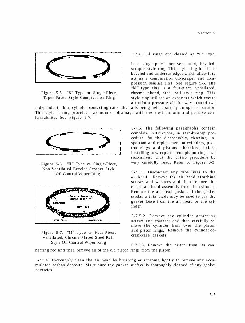
5-7.3. New replacement piston rings are of the quick-seating-type in that they are distin-guished by their narrow seating edge where they contact the cylinder wall. Compressionrings are classed as “B” type rings and are single-piece, taper-faced style; they have a slighttaper machined on their outer surface to provide line contact with the cylinder wall forquicker seating and better oil control. See Figure 5-5.
5-4
Section V
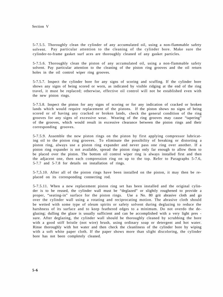
5-7.4. Oil rings are classed as “H” type,
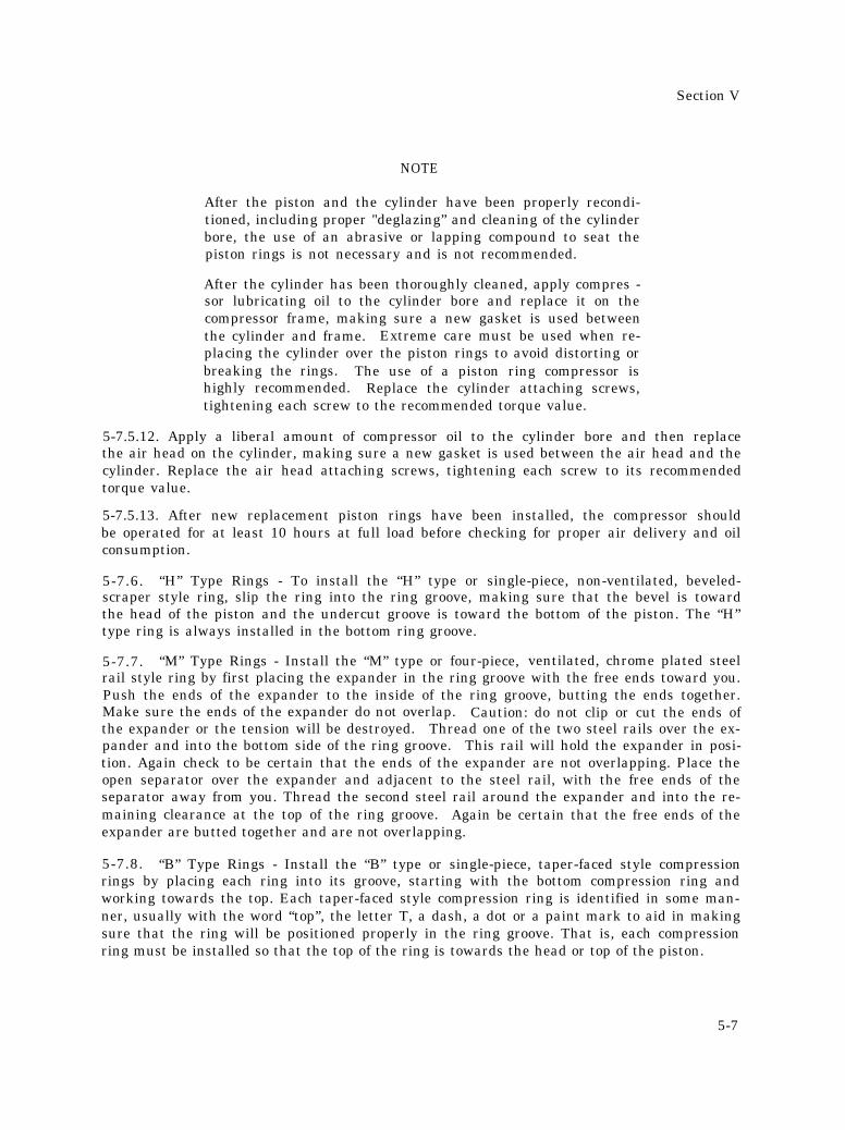
is a single-piece, non-ventilated, beveled-scraper style ring. This style ring has bothbeveled and undercut edges which allow it toact as a combination oil-scraper and com-pression sealing ring. See Figure 5-6. The“M” type ring is a four-piece, ventilated,
Figure 5-5. “B” Type or Single-Piece, chrome plated, steel rail style ring. ThisTaper-Faced Style Compression Ring style ring utilizes an expander which exerts
a uniform pressure all the way around twoindependent, thin, cylinder contacting rails, the rails being held apart by an open separator.This style of ring provides maximum oil drainage with the most uniform and positive con-formability. See Figure 5-7.
Figure 5-6. “H” Type or Single-Piece,Non-Ventilated Beveled-Scraper Style
Oil Control Wiper Ring
Figure 5-7. “M” Type or Four-Piece,Ventilated, Chrome Plated Steel Rail
Style Oil Control Wiper Ring
5-7.5. The following paragraphs containcomplete instructions, in step-by-step pro-cedure, for the disassembly, cleaning, in-spection and replacement of cylinders, pis -ton rings and pistons; therefore, beforeinstalling new replacement piston rings, werecommend that the entire procedure bevery carefully read. Refer to Figure 6-2.
5-7.5.1. Disconnect any tube lines to theair head. Remove the air head attachingscrews and washers and then remove theentire air head assembly from the cylinder.Remove the air head gasket. If the gasketsticks, a thin blade may be used to pry thegasket loose from the air head or the cyl-inder.
5-7.5.2. Remove the cylinder attachingscrews and washers and then carefully re-move the cylinder from over the pistonand piston rings. Remove the cylinder-to-crankcase gaskets.
5-7.5.3. Remove the piston from its con-necting rod and then remove all of the old piston rings from the piston.
5-7.5.4. Thoroughly clean the air head by brushing or scraping lightly to remove any accu-mulated carbon deposits. Make sure the gasket surface is thoroughly cleaned of any gasketparticles.
5-5
Section V
5-7.5.5. Thoroughly clean the cylinder of any accumulated oil, using a non-flammable safetysolvent. Pay particular attention to the cleaning of the cylinder bore. Make sure thecylinder-to-frame gasket surf aces are thoroughly cleaned of any gasket particles.
5-7.5.6. Thoroughly clean the piston of any accumulated oil, using a non-flammable safetysolvent. Pay particular attention to the cleaning of the piston ring grooves and the oil returnholes in the oil control wiper ring grooves.
5-7.5.7. Inspect the cylinder bore for any signs of scoring and scuffing. If the cylinder boreshows any signs of being scored or worn, as indicated by visible ridging at the end of the ringtravel, it must be replaced; otherwise, effective oil control will not be established even withthe new piston rings.
5-7.5.8. Inspect the piston for any signs of scoring or for any indication of cracked or brokenlands which would require replacement of the pistons. If the piston shows no signs of beingscored or of having any cracked or broken lands, check the general condition of the ringgrooves for any signs of excessive wear. Wearing of the ring grooves may cause “tapering”of the grooves, which would result in excessive clearance between the piston rings and theircorresponding grooves.
5-7.5.9. Assemble the new piston rings on the piston by first applying compressor lubricat-ing oil to the piston ring grooves. To eliminate the possibility of breaking or distorting apiston ring, always use a piston ring expander and never pass one ring over another. If apiston ring expander is not available, spread the piston rings only far enough to allow them tobe placed over the piston. The bottom oil control wiper ring is always installed first and thenthe adjacent one, then each compression ring on up to the top. Refer to Paragraphs 5-7.6,5-7.7 and 5-7.8 for details on installation of rings.
5-7,5.10. After all of the piston rings have been installed on the piston, it may then be re-placed on its corresponding connecting rod.
5-7.5.11. When a new replacement piston ring set has been installed and the original cylin-der is to be reused, the cylinder wall must be “deglazed” or slightly roughened to provide aproper, “seating-in" surface for the piston rings. Use a No. 80 grit abrasive cloth and goover the cylinder wall using a rotating and reciprocating motion. The abrasive cloth shouldbe wetted with some type of oleum spirits or safety solvent during deglazing to reduce theharshness of its surface and to keep feathered edges to a minimum. Do not overdo the de-glazing; dulling the glaze is usually sufficient and can be accomplished with a very light pres -sure. After deglazing, the cylinder wall should be thoroughly cleaned by scrubbing the borewith a good stiff bristle (not wire) brush, using ordinary soap or detergent and hot water.Rinse thoroughly with hot water and then check the cleanliness of the cylinder bore by wipingwith a soft white paper cloth. If the paper shows more than slight discoloring, the cylinderbore has not been completely cleaned.
5-6
Section V
NOTE
After the piston and the cylinder have been properly recondi-tioned, including proper "deglazing” and cleaning of the cylinderbore, the use of an abrasive or lapping compound to seat thepiston rings is not necessary and is not recommended.
After the cylinder has been thoroughly cleaned, apply compres -sor lubricating oil to the cylinder bore and replace it on thecompressor frame, making sure a new gasket is used betweenthe cylinder and frame. Extreme care must be used when re-placing the cylinder over the piston rings to avoid distorting orbreaking the rings. The use of a piston ring compressor ishighly recommended. Replace the cylinder attaching screws,tightening each screw to the recommended torque value.
5-7.5.12. Apply a liberal amount of compressor oil to the cylinder bore and then replacethe air head on the cylinder, making sure a new gasket is used between the air head and thecylinder. Replace the air head attaching screws, tightening each screw to its recommendedtorque value.
5-7.5.13. After new replacement piston rings have been installed, the compressor shouldbe operated for at least 10 hours at full load before checking for proper air delivery and oilconsumption.
5-7.6. “H” Type Rings - To install the “H” type or single-piece, non-ventilated, beveled-scraper style ring, slip the ring into the ring groove, making sure that the bevel is towardthe head of the piston and the undercut groove is toward the bottom of the piston. The “H”type ring is always installed in the bottom ring groove.
5-7.7. “M” Type Rings - Install the “M” type or four-piece, ventilated, chrome plated steelrail style ring by first placing the expander in the ring groove with the free ends toward you.Push the ends of the expander to the inside of the ring groove, butting the ends together.Make sure the ends of the expander do not overlap. Caution: do not clip or cut the ends ofthe expander or the tension will be destroyed. Thread one of the two steel rails over the ex-pander and into the bottom side of the ring groove. This rail will hold the expander in posi-tion. Again check to be certain that the ends of the expander are not overlapping. Place theopen separator over the expander and adjacent to the steel rail, with the free ends of theseparator away from you. Thread the second steel rail around the expander and into the re-maining clearance at the top of the ring groove. Again be certain that the free ends of theexpander are butted together and are not overlapping.
5-7.8. “B” Type Rings - Install the “B” type or single-piece, taper-faced style compressionrings by placing each ring into its groove, starting with the bottom compression ring andworking towards the top. Each taper-faced style compression ring is identified in some man-ner, usually with the word “top”, the letter T, a dash, a dot or a paint mark to aid in makingsure that the ring will be positioned properly in the ring groove. That is, each compressionring must be installed so that the top of the ring is towards the head or top of the piston.
5-7
Section V
5-8. SEPARATING THE PISTONnetting rod, proceed as follows:
FROM THE ROD. To separate the piston from the con-
5-8.1. Remove the air head cap screws (Figure 5-4) and pull the air head off the cylinder.If the gasket sticks, remove it with a thin blade.
5-8.2. Disconnect any assemblies or piping that may prevent removing the cylinder. Now,take out the cap screws securing the cylinder to the frame and pull the cylinder over thepiston.
5-8.3. To avoid bending the connecting rod when driving out the piston pin, we recommendremoving the piston and rod assembly from the crankshaft. To do this, drain the oil fromthe frame and remove the frame end cover. Then, take the centrifugal unloader assembly offthe end of the crankshaft and pull the connecting rod off its throw.
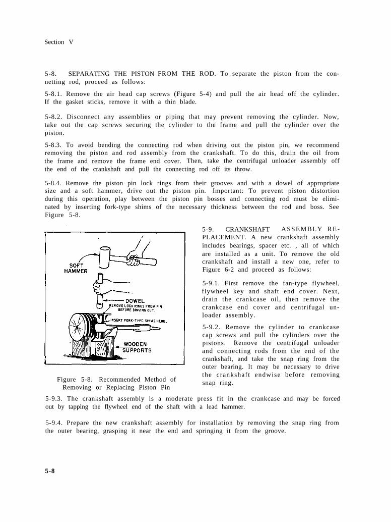
5-8.4. Remove the piston pin lock rings from their grooves and with a dowel of appropriatesize and a soft hammer, drive out the piston pin. Important: To prevent piston distortionduring this operation, play between the piston pin bosses and connecting rod must be elimi-nated by inserting fork-type shims of the necessary thickness between the rod and boss. SeeFigure 5-8.
Figure 5-8. Recommended Method ofRemoving or Replacing Piston Pin
5-9. CRANKSHAFT ASSEMBLY RE-PLACEMENT. A new crankshaft assemblyincludes bearings, spacer etc. , all of whichare installed as a unit. To remove the oldcrankshaft and install a new one, refer toFigure 6-2 and proceed as follows:
5-9.1. First remove the fan-type flywheel,flywheel key and shaft end cover. Next,drain the crankcase oil, then remove thecrankcase end cover and centrifugal un-loader assembly.
5-9.2. Remove the cylinder to crankcasecap screws and pull the cylinders over thepistons. Remove the centrifugal unloaderand connecting rods from the end of thecrankshaft, and take the snap ring from theouter bearing. It may be necessary to drivethe crankshaft endwisesnap ring.
5-9.3. The crankshaft assembly is a moderate press fit in the crankcaseout by tapping the flywheel end of the shaft with a lead hammer.
before removing
and may be forced
5-9.4. Prepare the new crankshaft assembly for installation by removing the snap ring fromthe outer bearing, grasping it near the end and springing it from the groove.
5-8
Section V
5-9.5. The new crankshaft may be inserted into the crankcase from the crankcase end coverside. Since the assembly is a moderate press fit, it may be forced into position by tapping itwith a lead hammer. (Be careful to strike the center of the shaft, since an off center blowmay spring it. )
5-9.6. The assembly must be driven in until the snap ring groove in the outer bearing clearsthe end of the crankcase by about 1/16”. Replace the snap ring by putting one end in thegroove and springing the ring into place.
5-9.7. Tap the crankshaft back until the snap ring is tight against the crankcase.
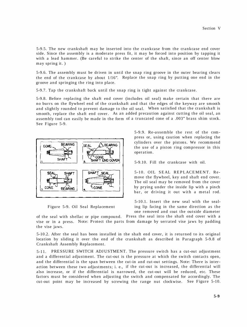
5-9.8. Before replacing the shaft end cover (includes oil seal) make certain that there areno burrs on the flywheel end of the crankshaft and that the edges of the keyway are smoothand slightly rounded to prevent damage to the oil seal. When satisfied that the crankshaft issmooth, replace the shaft end cover. As an added precaution against cutting the oil seal, anassembly tool can easily be made in the formSee Figure 5-9.
Figure 5-9. Oil Seal Replacement
of the seal with shellac or pipe compound.
of a truncated cone of a .003” brass shim stock.
5-9.9. Re-assemble the rest of the com-press or, using caution when replacing thecylinders over the pistons. We recommendthe use of a piston ring compressor in thisoperation.
5-9.10. Fill the crankcase with oil.
5-10. OIL SEAL REPLACEMENT. Re-move the flywheel, key and shaft end cover.The oil seal may be removed from the coverby prying under the inside lip with a pinchbar, or driving it out with a metal rod.
5-10.1. Insert the new seal with the seal-ing lip facing in the same direction as theone removed and coat the outside diameter
Press the seal into the shaft end cover with avise or in a press. Note: Protect the parts from damage by serrated vise jaws by paddingthe vise jaws.
5-10.2. After the seal has been installed in the shaft end cover, it is returned to its originallocation by sliding it over the end of the crankshaft as described in Paragraph 5-9.8 ofCrankshaft Assembly Replacement.
5-11. PRESSURE SWITCH ADJUSTMENT. The pressure switch has a cut-out adjustmentand a differential adjustment. The cut-out is the pressure at which the switch contacts open,and the differential is the span between the cut-in and cut-out settings. Note: There is inter-action between these two adjustments; i. e., if the cut-out is increased, the differential willalso increase, or if the differential is narrowed, the cut-out will be reduced, etc. Thesefactors must be considered when adjusting the switch and compensated for accordingly. Thecut-out point may be increased by screwing the range nut clockwise. See Figure 5-10.
5-9
Section V
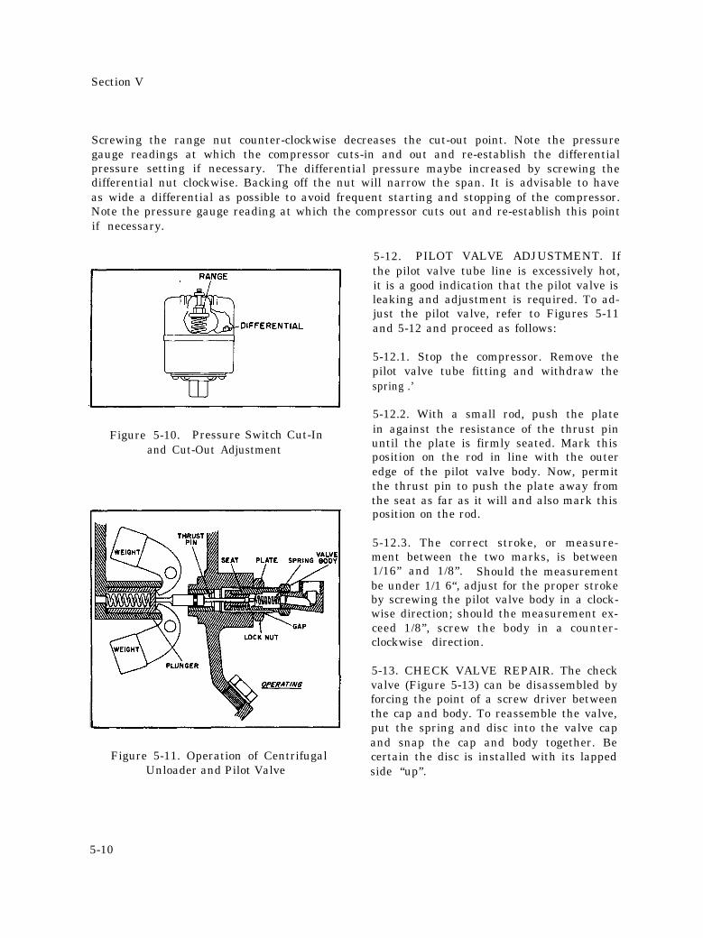
Screwing the range nut counter-clockwise decreases the cut-out point. Note the pressuregauge readings at which the compressor cuts-in and out and re-establish the differentialpressure setting if necessary. The differential pressure maybe increased by screwing thedifferential nut clockwise. Backing off the nut will narrow the span. It is advisable to haveas wide a differential as possible to avoid frequent starting and stopping of the compressor.Note the pressure gauge reading at which the compressor cuts out and re-establish this pointif necessary.
Figure 5-10. Pressure Switch Cut-Inand Cut-Out Adjustment
IFigure 5-11. Operation of Centrifugal
Unloader and Pilot Valve
5-12. PILOT VALVE ADJUSTMENT. Ifthe pilot valve tube line is excessively hot,it is a good indication that the pilot valve isleaking and adjustment is required. To ad-just the pilot valve, refer to Figures 5-11and 5-12 and proceed as follows:
5-12.1. Stop the compressor. Remove thepilot valve tube fitting and withdraw thespring .’
5-12.2. With a small rod, push the platein against the resistance of the thrust pinuntil the plate is firmly seated. Mark thisposition on the rod in line with the outeredge of the pilot valve body. Now, permitthe thrust pin to push the plate away fromthe seat as far as it will and also mark thisposition on the rod.
5-12.3. The correct stroke, or measure-ment between the two marks, is between1/16” and 1/8”. Should the measurementbe under 1/1 6“, adjust for the proper strokeby screwing the pilot valve body in a clock-wise direction; should the measurement ex-ceed 1/8”, screw the body in a counter-clockwise direction.
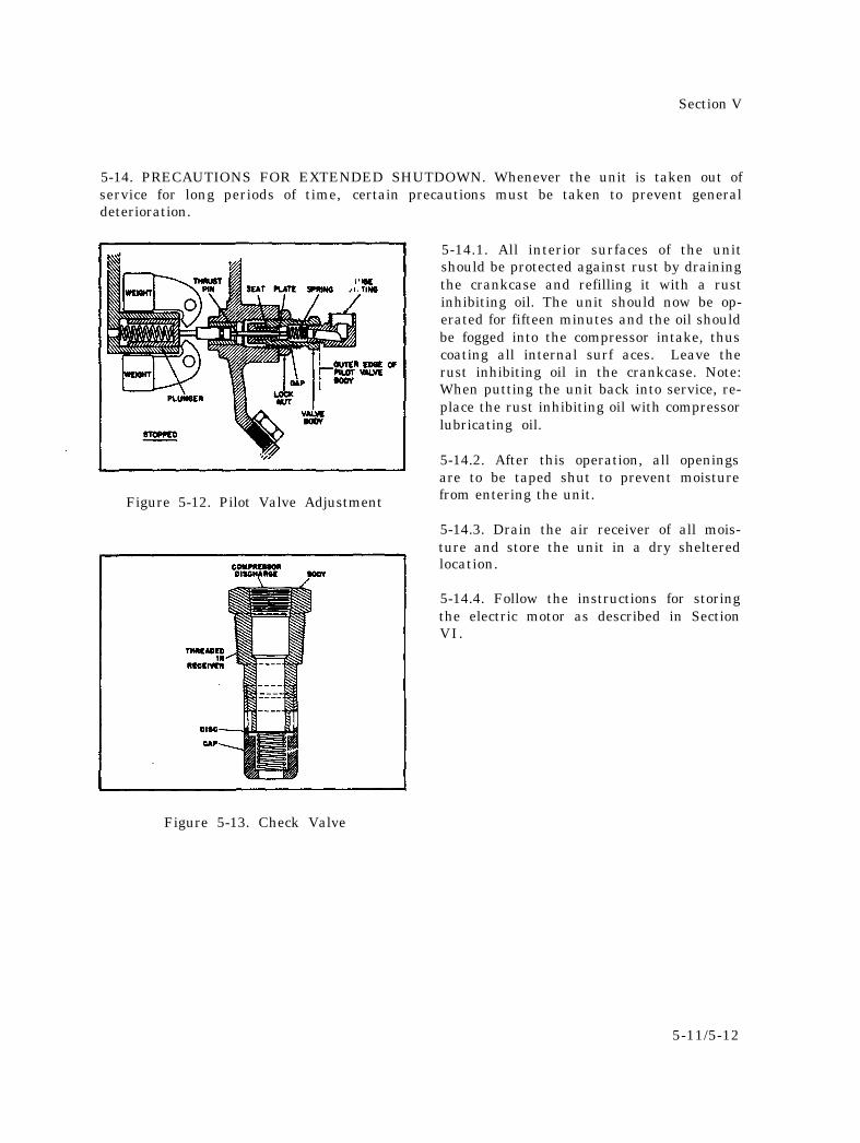
5-13. CHECK VALVE REPAIR. The checkvalve (Figure 5-13) can be disassembled byforcing the point of a screw driver betweenthe cap and body. To reassemble the valve,put the spring and disc into the valve capand snap the cap and body together. Becertain the disc is installed with its lappedside “up”.
5-10
Section V
5-14. PRECAUTIONS FOR EXTENDED SHUTDOWN. Whenever the unit is taken out ofservice for long periods of time, certain precautions must be taken to prevent generaldeterioration.
Figure 5-12. Pilot Valve Adjustment
5-14.1. All interior surfaces of the unitshould be protected against rust by drainingthe crankcase and refilling it with a rustinhibiting oil. The unit should now be op-erated for fifteen minutes and the oil shouldbe fogged into the compressor intake, thuscoating all internal surf aces. Leave therust inhibiting oil in the crankcase. Note:When putting the unit back into service, re-place the rust inhibiting oil with compressorlubricating oil.
5-14.2. After this operation, all openingsare to be taped shut to prevent moisturefrom entering the unit.
5-14.3. Drain the air receiver of all mois-ture and store the unit in a dry shelteredlocation.
5-14.4. Follow the instructions for storingthe electric motor as described in SectionVI.
Figure 5-13. Check Valve
5-11/5-12


Section VI.
SECTION VI
MISCELLANEOUS DATA
6 -1/6 -2

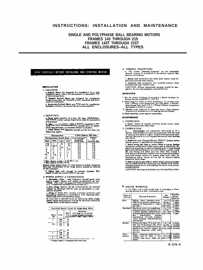
INSTRUCTIONS: INSTALLATION AND MAINTENANCE
SINGLE AND POLYPHASE BALL BEARING MOTORSFRAMES 143 THROUGH 215
FRAMES 143T THROUGH 215TALL ENCLOSURES–ALL TYPES
3NS1ALLA110N
1. LOCATION
?a.~ red &ton me designed for installation in s wellvenu med tdac.e where the atmosphere is reasonably fr~of dirt and momture.b. Stw&d Encfaood Moton me des@ed for insmllttionwhere motor,rnay be exposed to d,m mOlsture and mOstoutdoor c.mdmons.c. SCV.rC-&+VEIIC&d Mew lre desif wed for insmllatiOnin highly corroswe or excessively mmst atmospheres.
2. MOUNTINGs.kud motor securdY on a @m, flat base. All bsll-b+.ingmot?~s, excem verocslhufh.thmst,mayb mounted m● ny POsltlon.b. Af&nmtoraccumIely, usim$aflexible c0uplin6 if P?$sible. Fcmdrive recommendatmns consu2t drive or equ!p.mem manufacturer, or General Electric Company.c. V+f Shoavo Phch Ofam.1.n should no: be less than thefcdfowmg vduex,
Horsepower V-belt Sheave, Min—ia.Syncbrono.s Speed, RDm Coya:jyl” su3yt
3600 1800 1200 900 Pitch Dia. Outside Ok.
~% 34 2.2:.? 1$.2
2.2% 2.4 2.4
— 1!4 2.4 2.4~x 2.4 2.4
7 : ~ — 2.6 2.47% 3.0 3.0
10 7xi j- ; 3.0 3.0— - 3.0 3.0
1$ 10 — — 3.8 _ 3.8
● Max sheave width -2 (N-W)-!{”.f &xshewew#dth=N.W.
Sbesvemtios mterthan $:1 sndcenter-to-center dismnces.$Iesstlmn the mmeterofthe krgeshewes houldbereferred
to the Company.
$Shoufd not exceed 5000 ft.permi..n bdf8 only enough to prevent slippage. Belt
3. POWER SUPPLY. & CONNECTIONSa. ~ Volta. - and frequency should a ree with
“fPower sup IY. Motor will o race satisfactorily on lmeR“ ryoluse mm m 10c6qfnamep ate value ; or frequency with.m 5 ‘A combined vmmtio””otm exceed 10 Tc.
b“-”w’ motors can be c.mmcted for the desiredvol~ge by ollowmff mstruc! ions on nameplate or con.necuon dmgrsm.c. wb~ of motor and control, overload protection andgroun m should fw in accordance wi!h National Elec.micd Cc&.nd local building codes.1( wire size is selecmd from the fcdlmvin= table, si” le.
$phase motor performance WI
INSTRUCTIONS
CR105 MAGNETIC CONTRACTORS
CR106 MAGNETIC STARTERS
RATINGS
DESCRIPTIONThe CR105 is an open or enclosed
magnetic contactor.A CR106 full-voltage magnetic start-
er consists of one CR106 contactor andone or more CR124 overload relays. Theoverload relays provide motor protec-tion against running and stalled rotoroverloads. However, separate motorbranch circuit over-current protectionagainst electrical faults should be sup-plied in accordance with the NationalElectrical Code.
●
●●
●●●
●
●
FEATURESHorizontal straight-line motionmakes starter compact, easy tomaintain.Strongbox coil.Newly designed overload relays in-corporate dial for &1570 field ad-justment of tripping current, sothat it is no longer necessary tochange heaters to eliminate suchproblems as nuisance tripping inhot weather.Straight through wiring.Large combination knock outs.Oversized power terminals will ac-commodate up to #8 wire.Standard wire on open startersmeets JIC specifications.Starter can be disassembled in amatter of seconds.
INSTALLATIONBefore connecting starter to power
supply:1. Remove all packing.2. Clean magnet mating surfaces.S. Install overload relay heater(a).
To prevent overloading the starter, donot select heaters for a motor of alarger rating than given on the starternameplate. Select heater(s) in accord-ance with heater tables.
4. Operate movable magnet andoperating arm by pressing on the name-plate to assure free movement.
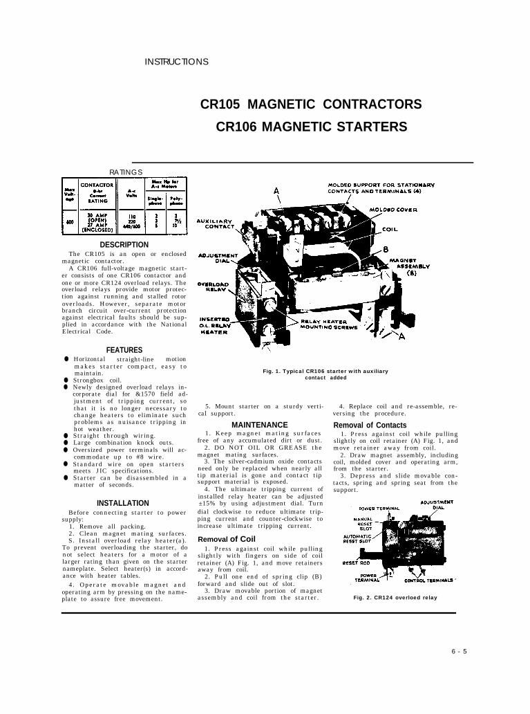
Fig. 1. Typical CR106 starter with auxiliarycontact added
5. Mount starter on a sturdy verti-cal support.
MAINTENANCE1. Keep magnet mating surfaces
free of any accumulated dirt or dust.2. DO NOT OIL OR GREASE the
magnet mating surfaces.3. The silver-cadmium oxide contacts
need only be replaced when nearly alltip material is gone and contact tipsupport material is exposed.
4. The ultimate tripping current ofinstalled relay heater can be adjusted±15% by using adjustment dial. Turndial clockwise to reduce ultimate trip-ping current and counter-clockwise toincrease ultimate tripping current.
Removal of Coil1. Press against coil while pulling
slightly with fingers on side of coilretainer (A) Fig. 1, and move retainersaway from coil.
2. Pull one end of spring clip (B)forward and slide out of slot.
3. Draw movable portion of magnetassembly and coil from the starter.
4. Replace coil and re-assemble, re-versing the procedure.
Removal of Contacts1. Press against coil while pulling
slightly on coil retainer (A) Fig. 1, andmove retainer away from coil.
2. Draw magnet assembly, includingcoil, molded cover and operating arm,from the starter.
3. Depress and slide movable con-tacts, spring and spring seat from thesupport.
Fig. 2. CR124 overloed relay
6 - 5
4. Remove screws which hold sta- Normaliy Closed Contacts facing opposite direction. Remove thetionary contacts to the molded support The contacts on this starter may be stationary contact as previously de-and remove the contacts. changed from normally open to nor- scribed. Install the operating arm forNote: For starters with one or more normallyclosed contacts, proceed with Stop I; then remove
really closed with no additional parts. movable contacts. Reinstall stationaryspring ClIP (B), and tak. tho coil, magnet a!scm. Disassemble the starter as previously contacts so silver-cadmium oxidr? padsbly and mold-d covar from the starter. Th*n re. described. Reverse spring and movable face movable contact pads.mow tht stationary contacts before removing thooperating ● rm for m.vabl. con facts. contact and re-install in upper position Re-assemble the starter.
To chance contacts from normally
1
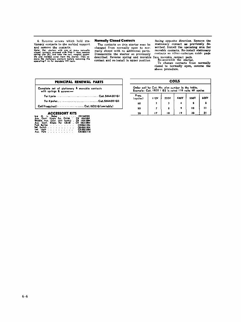
PRINCIPAL RENEWAL PARTS
Complcto sot of stationary & movable contact$with springs & srmews:—
For I polo . . . . . . . . . . . . . . . . . . . . . . . . . . . . . . . . . Cat. 546A301GI
For 4 poles . . . . . . . . . . . . . . . . . . . . . . . . . . . . . . . . . . . . . Cat. 546A301G2
Coil I I rcquirad) . . . . . . . . . . . . . . . . . . . . . . . . . . . . . . . . Cat. 15D21G (s.6 table)
ACCESSORY KITS3rd O. L. Relay . . . . . CR124C024AIM. Cent. Slnql. Fo, CRlti ;“ CR I05XIMPDoubl@ AUI. Cent. (All Form$) . CR IOSXIOONAIM. Cont. Sinqlo For CRI05 . CR IOSXIWM?uah Button CR IOSX120NSol. Swish.::::::::: CRI05X130NInd. light . . . . . . . . . . CRIOSX150NAux. PoIo . . . . . . . . . . CRI05XIIID
closed to ;ormally open, reverse th;above procedure.
COILSOrder coil by Cat. No. plus number in tho t~blc,Example: Cat. 15D2 I G2 is rated 110 volts 60 cycles
6-6
6 - 7
6 - 8
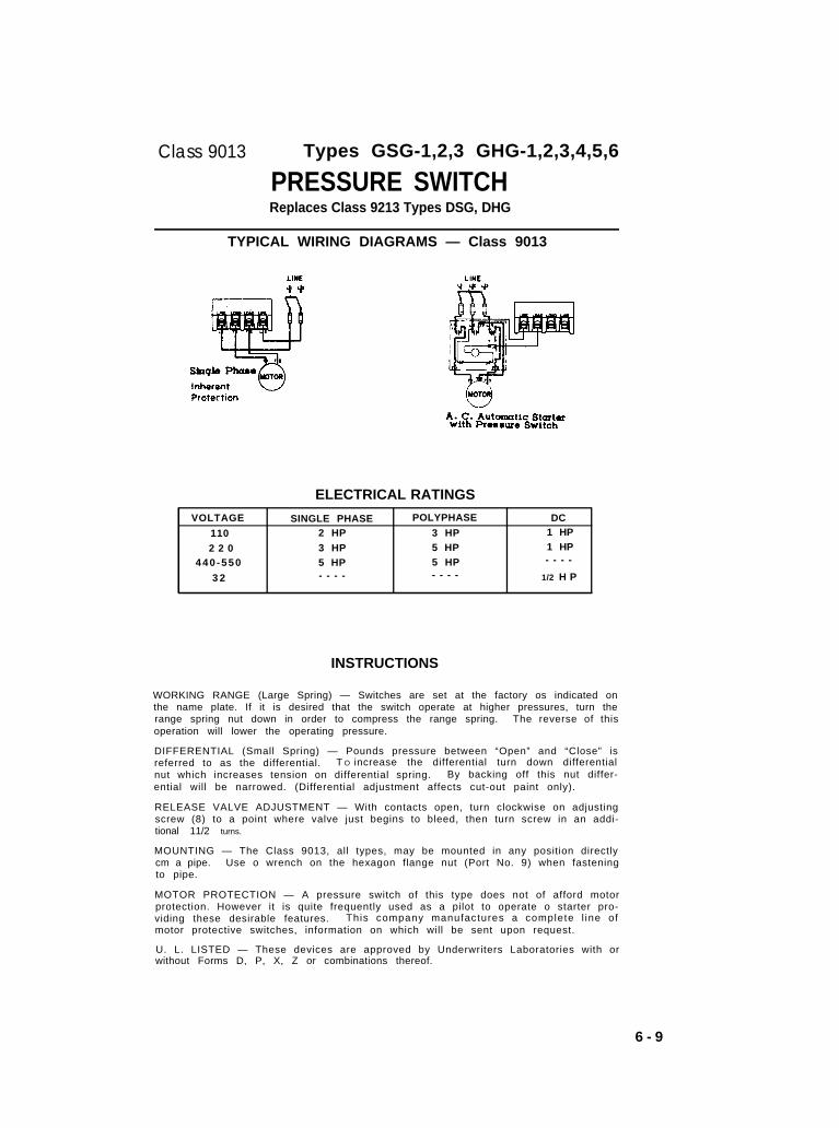
Class 9013 Types GSG-1,2,3 GHG-1,2,3,4,5,6
PRESSURE SWITCHReplaces Class 9213 Types DSG, DHG
TYPICAL WIRING DIAGRAMS — Class 9013
ELECTRICAL RATINGS
VOLTAGE SINGLE PHASE POLYPHASE DC
110 2 HP 3 HP 1 HP
2 2 0 3 HP 5 HP 1 HP
440 -550 5 HP 5 HP - - - -
3 2 - - - - - - - - 1/2 H P
INSTRUCTIONS
WORKING RANGE (Large Spring) — Switches are set at the factory os indicated onthe name plate. If it is desired that the switch operate at higher pressures, turn therange spring nut down in order to compress the range spring. The reverse of thisoperation will lower the operating pressure.
DIFFERENTIAL (Small Spring) — Pounds pressure between “Open” and “Close” isreferred to as the differential. T O increase the differential turn down differentialnut which increases tension on differential spring. By backing off this nut differ-ential will be narrowed. (Differential adjustment affects cut-out paint only).
RELEASE VALVE ADJUSTMENT — With contacts open, turn clockwise on adjustingscrew (8) to a point where valve just begins to bleed, then turn screw in an addi-tional 11/2 turns.
MOUNTING — The Class 9013, all types, may be mounted in any position directlycm a pipe. Use o wrench on the hexagon flange nut (Port No. 9) when fasteningto pipe.
MOTOR PROTECTION — A pressure switch of this type does not of afford motorprotection. However it is quite frequently used as a pilot to operate o starter pro-viding these desirable features. This company manufactures a complete l ine ofmotor protective switches, information on which will be sent upon request.
U. L. LISTED — These devices are approved by Underwriters Laboratories with orwithout Forms D, P, X, Z or combinations thereof.
6 - 9
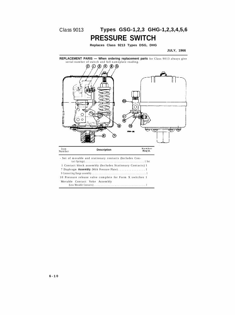
Class 9013 Types GSG-1,2,3 GHG-1,2,3,4,5,6
PRESSURE SWITCHReplaces Class 9213 Types DSG, DHG
JULY, 1966
REPLACEMENT PARIS — When ordering replacement parts for Class 9013 always giveserial number of switch and full nameplate reading.
ItemNumber Description N u m b e r
Req'd.
- Set of movable and stationary contacts (Includes Con-tact Springs) . . . . . . . . . . . . . . . . . . . . . . . . . . . . . . . . . . . . . . . . . . . . 1 Set
1 Contact block assembly (Includes Stationary Contacts) 17 Diaphragm Assembly (With Pressure Plate) . . . . . . . . . . . . . . . . 19 Connecting flange assembly . . . . . . . . . . . . . . . . . . . . . . . . . . . .. . . . . . . . . . . . . 1
10 Pressure release valve complete for Form X switches 1- Movable Contact Yoke Assembly
(Less Movable Contacts) . . . . . . . . . . . . . . . .. . . . . . . . . . . . . . . . . . . . . . 1
6 - 1 0
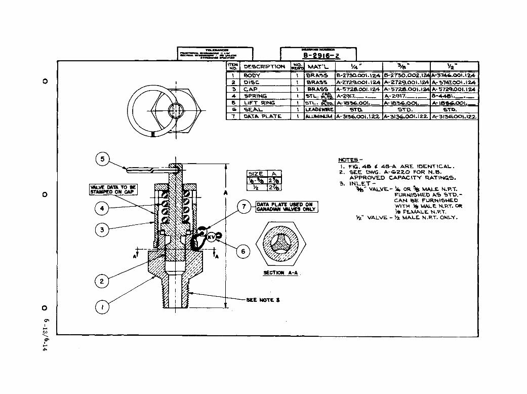
Maintenance, Service and Adjusting Instructions For Safety & Relief Valves
If valves are to be popped by hand, pressure should be at least 75% of set pressure toprevent foreign material from becoming caught between seat and disc. The recommend-ed procedure is to pop the valve” by-running pressure up to set pressure of valve.
Valve failure may be caused by seizing of parts, scored or wire drawn seats and over-
tightening valve in bushing, heavy discharge piping supported directly by valve, operat-ing pressure too close to set pressure of valve and corroded or eroded springs. Thefirst case may be corrected by careful cleaning followed by light sanding of the seatingsurfaces. For correction of the second, safety valves are susceptible of re-machining
of seating surfaces to angles shown on part drawings, or careful hand lapping if damageis less severe. Springs rarely require replacement, but may be purchased from manu-
facturer as a unit of spare parts should replacement be necessary.
D I S M A N T L I N G
1. Remove lifting gear and/or hood and mark relative positions of pressure screw,locknut and cap.
2. Loosen pressure screw locknut and pressure screw to release pressure on spring.3. Remove cap.4 . Remove sp ind le , d isc and guide .
5 . M a r k l o c a t i o n o f r e g u l a t o r r i n g ( s ) i f u s e d a n d r e m o v e i t .
To reassemble, reverse the above procedure, being careful to return parts to theirmarked positions and replace all gaskets. Re-set valves according to instructions below.
ADJUSTMENT, SETTING and TESTING
Popping Pressure or Cracking Pressure. Make sure of gauge accuracy before begin-ning. Remove lifting gear and hood exposing pressure screw and locknut. Loosenlocknut and raise pressure until valve pops. If opening pressure is too low, turn downon pressure screw. If pressure is too high, reverse pressure screw. After properpressure has been reached securely tighten locknut.
Blowdown Adjustment, Steam, Air, Gas Valves Only. When popping pressure ischanged, a slight adjustment in blowdown may be required. Raising the popping pres-sure lengthens blowdown and lowering the popping pressure shortens blowdown. Ra i s -ing the regulator ring toward the disc will increase blowdown and lowering the ringwill decrease blowdown. Regulator ring adjustments should be made a notch at a timeas the adjustment is sensitive. The normal position would be six (6) notches downfrom touching the disc, but this figure will vary with conditions.
CAUTION: Re-tighten regulator ring set screw being careful that it rests in notcheswithout gouging ring surface. Adjusting regulator ring may cause valve to pop if it iss immer ing . Keep hands and face clear of outlet.
6 - 1 1 / 6 - 1 2

6-13
SE
CT
ION
A-A
FIG
. 48

APPENDIX A
MAINTENANCE ALLOCATION CHART
Sect ion I . INTRODUCTION
A - 1 . General
a . This appendix provides a general explanation of all maintenance andrepair functions authorized at various maintenance levels.
b . Section I I designates overall responsibil i ty for the performanceof maintenance functions on the identified end item or component. The im-plementation of the maintenance functions upon the end item or componentwill be consistent with the assigned maintenance functions.
c . Section I I I is n o t a p p l i c a b l e .
d . Section IV is not applicable.
A-2. Explanation of Columns in Section I I
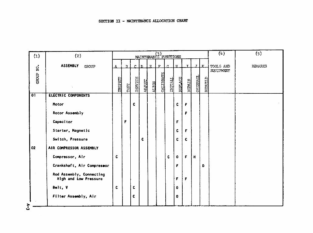
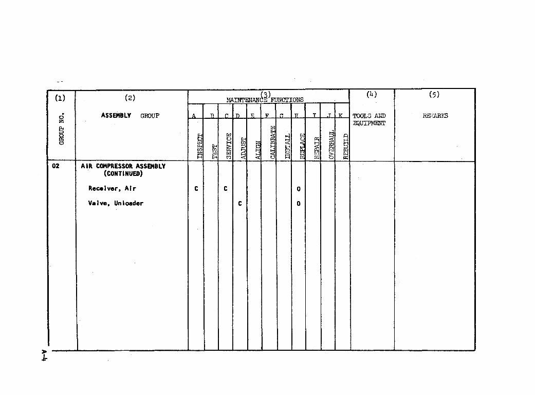
a . Group Number. Column 1. The assembly group is a numerical groupassigned to each assembly in a top down breakdown sequence. The appli-cable assembly groups are listed on the MAC in disassembly sequence be-ginning with the first assembly removed in a top down disassembly sequence.
b . Assembly Group. Column 2. This column contains a brief descrip-tion of the components of each assembly group.
c . Maintenance Functions. Column 3. This column lists the variousmaintenance functions (A through K) and indicates the lowest maintenancecategory authorized to perform these functions. The symbol designationsfor the various maintenance categories are as follows:
C - Operator or crewO - organizational maintenanceF - Direct support maintenanceH - General support maintenanceD - Depot maintenance
The maintenance functions are defined as follows:
A - INSPECT. To determine serviceability of an item by comparingits physical, mechanical , and electrical characteristics with establishedstandards.
B - TEST. To verify serviceabil ity and to detect electrical or me-chanical failure by use of test equipment.
A-1
c - SERVICE. 10 clean, to preserve, to charge, and to add fuel,lubricants, cooling agents, and air. I f i t is desired that elements,such as painting and lubricating, be defined separately, they may be sol i s t e d .
D - ADJUST. To rectify to the extent necessary to bring intoproper operating range.
E -ALIGN. To adjust specified variable elements of an item tobring to optimum performance.
F - CALIBRATE. To determine the corrections to be made in the read-ings of instruments or test equipment used in precise measurement. Con-sists of the comparison of two instruments , one of which is a certif iedstandard of known accuracy, to detect and adjust any discrepancy in theaccuracy of the instrument being compared with the certified standard.
G - INSTALL.as an emplacement,
H - REPLACE.i terns.
To set up for use in an operatis i te , or vehic le .
To replace unserviceable items
onal environment such
with serviceable l ike
I - REPAIR. Those maintenance operations necessary to restore anitem to serviceable condition through-correction of material damage ora speci f ic fa i lure . Repair may be-accomplished at each category ofmaintenance.
J - OVERHAUL. Normally, the highest degree of maintenance performedby the Army in order to minimize time work in process is consistent withquality and economy of operation. it oonsists of that maintenance ne-cessary to restore an item to completely serviceable condition as pre-scribed by maintenance standards in technical publications for eachitem of equipment. Overhaul normally does not return an item to likenew, zero mileage, or zero hour condition.
K - REBUILD. The highest degree of materiel maintenance. It con-sists of restoring equipment as nearly as possible to new condition inaccordance with original manufacturing standards. Rebuild is performedonly when required by operational considerations or other paramount factorsand then only at the depot maintenance category. Rebuiid reduces to zerothe hours of miles the equipment, or component thereof, has been in use.
d_. Tools and Equipment. Column 4. This column is not applicable.
e . Remarks. Column 5. This column is not applicable.
A-2
SE
CT
ION
II
A-3
A-4
APPENDIX B
BASIC ISSUE ITEMS LIST
Section I. INTRODUCTION
B-1. Scope
This appendix lists items which accompany the Air Compressor or arerequired for installation, operation, or operator’s maintenance.
B-2 . GeneraI
This Basic Issue Items List is divided into the following sections:
_. Basic Issue Items - Section Il. A list of items whichapany the Air Compressor and are required by the operator/crewstallation, operation, or maintenance.
b . Maintenance and Operating Supplies - Section Ill. NOT
B-3 . Explanation of Columns
accom-for in-
APPLICABLE
The following provides an explanation of columns in the tabularlist of Basic Issue Items, Section Il.
a. Source. Maintenance. and Recoverability Codes (SMR):
(1) Source code, indicates the source for the 1 is ted i tam. Source
codes are:
Code
P
M
A
Repair parts which areGSA/DSA or Army supply
Explanation
stocked in or supplied from thesystem and authorized for use at.
indicated maintenance categories.
Repair parts which are not procured or stocked, but are tobe manufactured in indicated maintenance levels.
Assemblies which are not procured or stocked as such, butare made up of two or more units. Such component unitscarry individual stock numbers and descriptions, are pro-cured and stocked separately and can be assembled to formthe required assembly at indicated maintenance categories.
B-1
Code Explanation
X Parts and assemblies which are not procured or stockedand the mortality of which normally is below that of theapplicable end item or component. The failure of suchpart or assembly should result in retirement of the enditem from the supply system.
X1 Repair parts which are not procured or stocked. The re-quirement for such items will be filled by use of thenext higher assembly or component.
X2 Repair parts which are not stocked. The indicated mainte-nance category requiring such repair parts will attemptto obtain them through cannibalization. Where such re-pair parts are not obtainable through cannibalization,requirements will be requisitioned, with accompanyingjustification, through normal supply channels.
G Major assemblies that are procured with PEMA funds forinitial issue only as exchange assemblies at DSU andGSU level. These assemblies will not be stocked aboveGS and DS Ievel or returned to depot supply level.
(2) Maintenance code, indicates the lowest category of mainte-nance authorized to install the listed item. The maintenance levelcode is:
Code Explanation
C Operator/crew
(3) Recoverability code, indicates whether unserviceable itemsshould be returned for recovery or salvage. Items not coded are ex-pendable. Recoverability codes are:
Code Explanation
R Repair parts (assemblies and components) which are con-sidered economically reparable at direct and generalsupport maintenance levels. When the maintenancecapability to repair these items does not exist, theyare normally disposed of at the GS level. When supplyconsiderations dictate, some of these repair parts maybe listed for automatic return to supply for depot levelrepair as set forth in AR 710-50. When so listed, theywill be replaced by supply on an exchange basis.
B-2
ExplanationCode
s
T
Repair parts and assemblies which are economically re-parable at DSU and GSU activities and which normallyare furnished by supply on an exchange basis. Whenitems are determined by a GSU to be uneconomically re-parable they will be evacuated to a depot for evaluationand analysis before final disposition.
High dollar value recoverable repair parts which are sub-ject to special handling and are issued on an exchangebasis. Such repair parts normally are repaired or over-hauled at depot maintenance activities.
U Repair parts specifically selected for salvage by reclama-tion units because of precious metal content, criticalmaterials, or high dollar value reusable casings or castings.
b Federal Stock Number. This column indicates the Federal stocknumber assigned to the item and will be used for requisitioning pur-poses.
c . Description. This column indicates the Federal item name andany additional description of the item required.
d . Unit of Pleasure (U/M). A 2 character alphabetic abbreviationindicating the amount or quantity of the item upon which the allowancesare based, e.g., ft, ea, pr, etc.
e . Quantity incorporated in Unit. This column indicates the quan-tity of the item used in the assembly group.
f. Quantity Furnished With Equipment. This column indicates thequantity of an item furnished with the equipment.
g . I l lustrat ion. This column is not applicable.
8-3
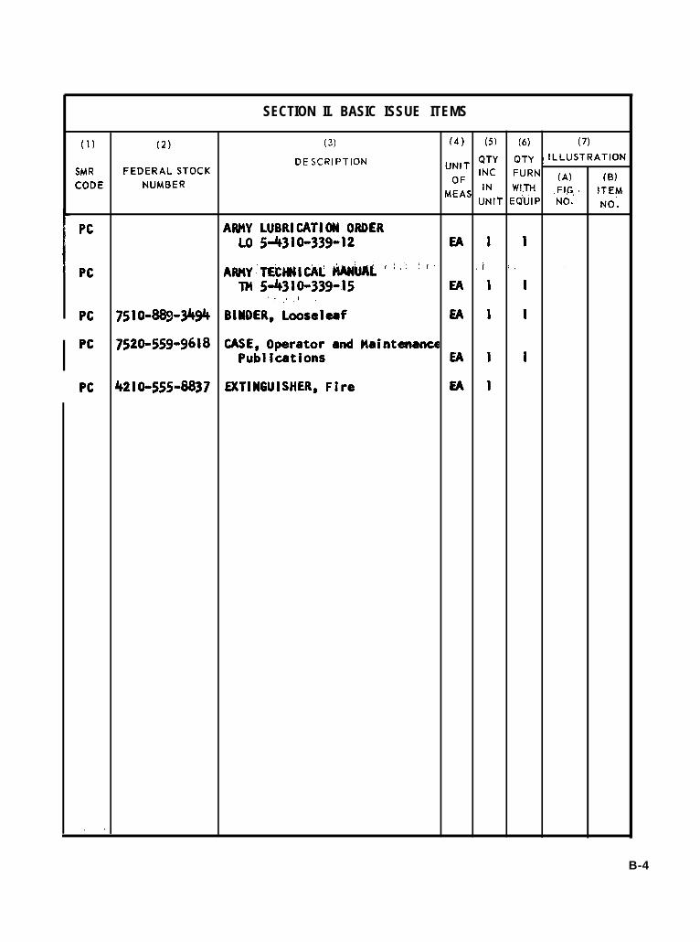
SECTION II. BASIC ISSUE ITEMS
(1) (2) (3) (4) (5) (6) (7)
DESCRIPTION “NIT QTY QTY ! ILLUSTRATIONSMR FEDERAL STOCK INC FURNCODE NUMBER OF (A) (B)
MEASIN . WITI+ Fl,q ~ ITEM
UNIT EQUIP ‘No. No;
Pc ARMY LUBRICATION ORDERLO 5-4310-339-12 EA 1 I
Pc Af#tY’TE?Mltiti @UIIkp’’ ”’”: “ ‘i “’ ‘m 5-4310-339-15 EA I 1
:;!, (,,,
Pc 7510-889-3494 BIUDER, Looseleaf EA I 1
Pc 7520-559-9618 CASE, Operator and MaintenancePublications EA 1 1
Pc 4210-555-8837 EXTINGUISHER, Fire EA i
,.
B-4
By Order of the Secretary of the Army:
Official:KENNETH G. WICKHAM,Major General, United States Army,The Adjutant General.
W. C. WESTMORELAND,Gem-al, United States Amy,Chief of Staff
Distribution:To redistributed in accordance with DA Form 12-25, Section I, (qty rqr block No. 18) organizational maintenance requirements for
Compressors: 15 CFM.
U.S. GOVERNMENT PRINTING OFFICE: 1970-397092/5034


TM
5-4
310-
339-
15

This fine document...
Was brought to you by me:
Liberated Manuals -- free army and government manuals
Why do I do it? I am tired of sleazy CD-ROM sellers, who take publicly available information, slap “watermarks” and other junk on it, and sell it. Those masters of search engine manipulation make sure that their sites that sell free information, come up first in search engines. They did not create it... They did not even scan it... Why should they get your money? Why are not letting you give those free manuals to your friends?
I am setting this document FREE. This document was made by the US Government and is NOT protected by Copyright. Feel free to share, republish, sell and so on.
I am not asking you for donations, fees or handouts. If you can, please provide a link to liberatedmanuals.com, so that free manuals come up first in search engines:
<A HREF=http://www.liberatedmanuals.com/>Free Military and Government Manuals</A>
– SincerelyIgor Chudovhttp://igor.chudov.com/
– Chicago Machinery Movers