Embed Size (px)
Citation preview
* TM 55-1520-228-10TECHNICAL MANUAL
OPERATOR’S MANUALARMY MODEL OH-58 A/C
HELICOPTER
DISTRIBUTION STATEMENT A: Approved for public release; distribution is unlimited.
* THIS MANUAL SUPERSEDES TM 55-1520-228-10 AND TM 55-1520-235-10, 7 APRIL 1978, INCLUDING ALLCHANGES.
HEADQUARTERS, DEPARTMENT OF THE ARMY
17 JANUARY 1989

TM 55-1520-228-10
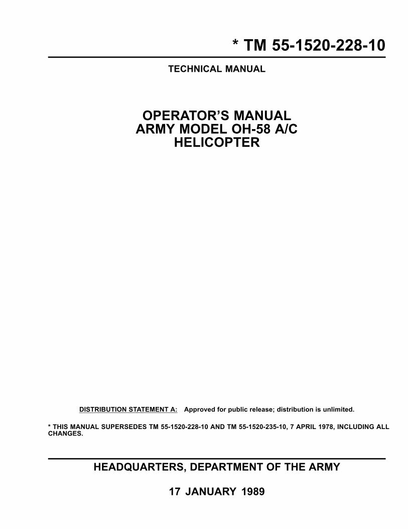
An operating procedure, practice, etc., which, if not correctly followed, could result in personnelinjury or loss of life.
An operating procedure, practice, etc., which, if not strictly observed, could result in damage to ordestruction of equipment.
NOTE
An operating procedure, condition, etc., which it is essential to highlight.
PRECAUTIONARY DATAPersonnel performing operations, procedures and practices which are included or implied in this technical manualshall observe the following warnings. Disregard of these warnings or precautionary information can cause seriousinjury or loss of life.
STARTING ENGINE
Coordinate all cockpit actions with ground observer. Ensure that rotors and blast areas are clear and re guard isposted, if available.
FIRE EXTINGUISHER
Exposure to high concentrations of monobromotribluoromethane (CF Br) extinguishing agent or toxic fumes pro-duced by the agent should be avoided. The liquid should not be allowed to come into contact with the skin, as it maycause frostbite or low temperature burns.
GROUND OPERATION
Engines will be started and operated only by authorized personnel. Reference AR 95-1.
ELECTROLYTE
Battery electrolyte is harmful to the skin and clothing. Neutralize any spilled electrolyte by ushing contacted areasthoroughly with water.
Change 12 a
TM 55-1520-228-10
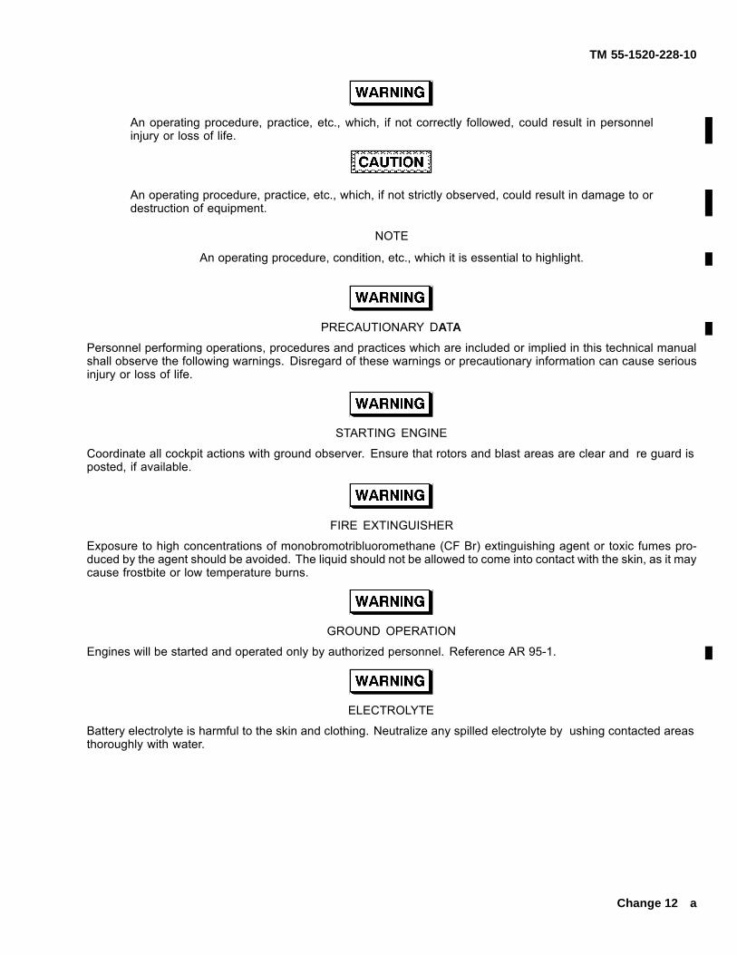
CARBON MONOXIDE
When smoke, suspected carbon monoxide fumes, or symptoms of anoxia exist, the crew should immediately venti-late cabin and shut off heater.
HANDLING FUEL AND OILS
Turbine fuels and lubricating oil contain additives which are poisonous and readily absorbed through the skin. Donot allow them to remain on skin longer than necessary.
HANDLING HYDRAULIC FLUID (MIL-H-83282)
Prolonged contact with liquid or mist can irritate eyes and skin. After prolonged contact with skin, immediately washcontacted area with soap and water. If liquid contacts eyes, ush immediately with clean water. If liquid is swallowed,do not induce vomiting; get immediate medical attention. Wear rubber gloves when handling liquid. If prolongedcontact with mist is likely, wear an appropriate respirator. When uid is decomposed by heating, toxic gases arereleased.
HAZARDOUS CARGO
Items of cargo possessing dangerous physical properties, such as explosives, acids, ammable, etc., must be han-dled with extreme caution and in accordance with established regulations. Refer to TM 38-250.
NOISE
Sound pressure levels in this aircraft during some operating conditions exceed the Surgeon General’s hearing con-servation criteria as de ned in TB MED 501. Hearing protection devices, such as the aviator helmet or earplugs arerequired to be worn by all personnel in and around the aircraft during its operation.
b Change 14
TM 55-1520-228-10C17
CHANGE
NO. 17
HeadquartersDepartment of the Army
Washington, D.C.,19 FEBRUARY 2010
OPERATOR’S MANUALARMY MODEL OH-58A/C HELICOPTER
���������� ����� �� �� �������� ��� ������ �������� ������������ �� ���� ����!
� ""#$"%&#%%'#$&( $) *�����+ $,',( �� �-��.�� �� �����/��
$! �� ��� ��� ������ ��.�� �� ��������� ����/! �/ �� �-��.�� ��0� ������� �� ��������� �+ � �������� ����� �-� ��.��! �� ������������ �-��.� �� ��������� �+ � �������� �������. -���!
�� ��� 1�.�� ������ 1�.��
� �-���.- 234� ����56 � �-���.- 234� ����56,#) ��� ,#' ,#) ��� ,#'
%! ������ �-�� �-��� �� ����� �� ����� ��� ��������� ��������!
By Order of the Secretary of the Army:
GEORGE W. CASEY, JR.
General, United States Army Chief of Staff
$&&3405
JOYCE E. MORROW Administrative Assistant to the
Secretary of the Army
Official:
Distribution: To be distributed in accordance with the initial distribution number (IDN) 310230 requirements for TM 55-1520-228-10.

TM 55-1520-228-10C16
CHANGE
NO. 16
HeadquartersDepartment of the Army
Washington, D.C.,30 September 2009
OPERATOR’S MANUALARMY MODEL OH-58A/C HELICOPTER
DISTRIBUTION STATEMENT A: Approved for public release; distribution is unlimited.
TM 55-1520-228-10, 17 January 1989, is changed as follows:
1. Remove and insert pages as indicated below. New or changed text material is indicated by a vertical barin the margin. An illustration change is indicated by a miniature pointing hand.
Remove Pages Insert Pages
A through C/(D blank) A through C/(D blank)9-7 and 9-8 9-7 and 9-8
2. Retain this sheet in front of manual for reference purposes.
By Order of the Secretary of the Army:
GEORGE W. CASEY, JR.
General, United States Army Chief of Staff
0925806
JOYCE E. MORROW Administrative Assistant to the
Secretary of the Army
Official:
Distribution: To be distributed in accordance with the initial distribution number (IDN) 310230 requirements for TM 55-1520-228-10.
TM 55-1520-228-10C15
CHANGE
NO. 15
HeadquartersDepartment of the Army
Washington, D.C.,24 December 2007
OPERATOR’S MANUAL ARMY MODEL OH-58A/C HELICOPTER
DISTRIBUTION STATEMENT A: Approved for public release; distribution is unlimited.
TM 55-1520-228-10, 17 January 1989, is changed as follows:
1. Remove and insert pages as indicated below. New or changed text material is indicated by a vertical barin the margin. An illustration change is indicated by a miniature pointing hand.
Remove Pages Insert Pages
A through C/(D blank) A through C/(D blank)5-7 and 5-8 5-7 and 5-87-81 through 7-85/(7-86 blank) 7-81 through 7-83/(7-84 blank)8-7 and 8-8 8-7 and 8-89-5 and 9-6 9-5 and 9-69-13 through 9-15/(9-16 blank) 9-13/(9-14 blank)A-1 and A-2 A-1/(A-2 blank)Glossary-1 and Glossary-2 Glossary-1 and Glossary-2
2. Retain this sheet in front of manual for reference purposes.
By Order of the Secretary of the Army:
GEORGE W. CASEY, JR. General, United States Army
Chief of StaffOfficial:
JOYCE E. MORROW Administrative Assistant to the
Secretary of the Army 0733129
DISTRIBUTION:
To be distributed in accordance with Initial Distribution Number (IDN) 310230, requirementsfor TM 55-1520-228-10.

TM 55-1520-228-10C14
CHANGE
NO. 14
HeadquartersDepartment of the Army
Washington, D.C.,31 March 2006
OPERATOR’S MANUAL ARMY MODEL OH-58A/C HELICOPTER
DISTRIBUTION STATEMENT A: Approved for public release; distribution is unlimited.
TM 55-1520-228-10, 17 January 1989, is changed as follows:
1. Remove and insert pages as indicated below. New or changed text material is indicated by a vertical barin the margin. An illustration change is indicated by a miniature pointing hand.
Remove Pages Insert Pages
a and b a and bA and B A and B2-1 through 2-4 2-1 through 2-42-7 through 2-10 2-7 through 2-102-13 and 2-14 2-13 and 2-142-23 and 2-24 2-23 and 2-242-29 and 2-30 2-29 and 2-302-35 through 2-38 2-35 through 2-382-46.1 and 2-46.2 2-46.1 and 2-46.22-49 through 2-52 2-49 through 2-522-57 and 2-58 2-57 and 2-583-3 and 3-4 3-3 and 3-45-1 and 5-2 5-1 and 5-2(5-3 blank)/5-4 through 5-12 (5-3 blank)/5-4 through 5-126-1 and 6-2 6-1 and 6-28-5 through 8-8 8-5 through 8-88-11 through 8-14 8-11 through 8-149-1 through 9-13/(9-14 blank) 9-1 through 9-13/(9-14 blank)
Retain this sheet in front of manual for reference purposes.
By Order of the Secretary of the Army:
PETER J. SCHOOMAKER
General, United States Army
Chief of Staff
OFFICIAL:
JOYCE E. MORROW
Administrative Assistant to the
Secretary of the Army0528701

TM 55-1520-228-10C14
DISTRIBUTION: To be distributed in accordance with Initial Distribution Number (IDN) 310230, requirementsfor TM 55-1520-228-10.
TM 55-1520-228-10C13
CHANGE
NO. 13
HeadquartersDepartment of the Army
Washington, D.C.,30 August 2005
OPERATOR’S MANUAL ARMY MODEL OH-58A/C HELICOPTER
DISTRIBUTION STATEMENT A: Approved for public release; distribution is unlimited.
TM 55-1520-228-10, 17 January 1989, is changed as follows:
1. Remove and insert pages as indicated below. New or changed text material is indicated by a vertical barin the margin. An illustration change is indicated by a miniature pointing hand.
Remove Pages Insert Pages
A and B A and B2-11 and 2-12 2-11 and 2-12(5-3 blank) and 5-4 (5-3 blank) and 5-4
Retain this sheet in front of manual for reference purposes.
By Order of the Secretary of the Army:
PETER J. SCHOOMAKER
General, United States Army
Chief of Staff
OFFICIAL:
SANDRA R. RILEY
Administrative Assistant to the
Secretary of the Army0519202
DISTRIBUTION: To be distributed in accordance with Initial Distribution Number (IDN) 310230, requirementsfor TM 55-1520-228-10.

TM 55-1520-228-10C12
CHANGE
NO. 12
HeadquartersDepartment of the Army
Washington, D.C.,10 June 2005
OPERATOR’S MANUAL ARMY MODEL OH-58A/C HELICOPTER
DISTRIBUTION STATEMENT A: Approved for public release; distribution is unlimited.
TM 55-1520-228-10, 17 January 1989, is changed as follows:
1. Remove and insert pages as indicated below. New or changed text material is indicated by a vertical barin the margin. An illustration change is indicated by a miniature pointing hand.
Remove Pages Insert Pages
a and b a and bA and B A and B2-1 through 2-12 2-1 through 2-122-27 and 2-28 2-27 and 2-282-37 and 2-38 2-37 and 2-382-43 and 2-44 2-43 and 2-442-49 through 2-52 2-49 through 2-522-55 through 2-60 2-55 through 2-602-63 and 2-64 2-63 and 2-64(5-3 blank)/ 5-4 (5-3 blank)/ 5-47-79 and 7-80 7-79 and 7-808-7 and 8-8 8-7 and 8-89-7 and 9-8 9-7 and 9-8
Retain this sheet in front of manual for reference purposes.
By Order of the Secretary of the Army:
PETER J. SCHOOMAKER
General, United States Army
Chief of Staff
OFFICIAL:
SANDRA R. RILEY
Administrative Assistant to the
Secretary of the Army0512202
DISTRIBUTION: To be distributed in accordance with Initial Distribution Number (IDN) 310230, requirementsfor TM 55-1520-228-10.


TM 55-1520-228-10C11
CHANGE
NO. 11
HeadquartersDepartment of the Army
Washington, D.C.,1 April 2003
OPERATOR’S MANUAL ARMY MODEL OH-58A/C HELICOPTER
DISTRIBUTION STATEMENT A: Approved for public release; distribution is unlimited.
TM 55-1520-228-10, 17 January 1989, is changed as follows:
1. Remove and insert pages as indicated below. New or changed text material is indicated by a vertical barin the margin. An illustration change is indicated by a miniature pointing hand.
Remove Pages Insert Pages
a and b a and bA and B A and Bi through iv i through iv1-1 and 1-2 1-1 and 1-22-1 through 2-4 2-1 through 2-42-11 through 2-14 2-11 through 2-142-17 through 2-20 2-17 through 2-202-23 through 2-26 2-23 through 2-262-27 through 2-30 2-27 through 2-302-33 and 2-34 2-33 and 2-342-43 and 2-44 2-43 and 2-442-46.1 and 2-46.2 2-46.1 and 2-46.22-47 through 2-54 2-47 through 2-542-57 and 2-58 2-57 and 2-582-61 through 2-67/(2-68 blank) 2-61 through 2-67/(2-68 blank)3-1 through 3-8 3-1 through 3-83-8.1/(3-8.2 blank) 3-8.1 and 3-8.2— 3-8.3 and 3-8.43-11 through 3-14 3-11 through 3-143-17 through 3-20 3-17 through 3-203-23 and 3-24 3-23 and 3-243-24.1/(3-24.2 blank) 3-24.1/(3-24.2 blank)3-27 and 3-28 3-27 and 3-283-31 and 3-32 3-31 and 3-323-32.1 and 3-32.2 3-32.1 and 3-32.2— (3-32.3 blank)/3-32.43-33 through 3-36 3-33 through 3-365-1 through 5-10 5-1 through 5-106-1 through 6-7/(6-8 blank) 6-1 through 6-7/(6-8 blank)7-1 through 7-6 7-1 through 7-67-59 through 7-62 7-59 through 7-627-79 and 7-80 7-79 and 7-807-83 and 7-84 (7-83 blank)/7-848-1 through 8-8 8-1 through 8-88-8.1/(8-8.2 blank) —8-9 through 8-12 8-9 through 8-128-15 through 8-17/(8-18 blank) 8-15 through 8-17/(8-18 blank)9-1 and 9-2 9-1 and 9-29-7 and 9-8 9-7 and 9-89-11 through 9-14 9-11 through 9-14A-1/(A-2 blank) A-1 and A-2
TM 55-1520-228-10C11
Remove Pages Insert Pages
Index-1 through Index-9/(Index-10blank)
Index-1 through Index-9/(Index-10 blank)
Retain this sheet in front of manual for reference purposes.
By Order of the Secretary of the Army:
ERIC K. SHINSEKI
General, United States Army
Chief of Staff
OFFICIAL:
JOEL B. HUDSON
Administrative Assistant to the
Secretary of the Army0304901
DISTRIBUTION: To be distributed in accordance with Initial Distribution Number (IDN) 310230, requirementsfor TM 55-1520-228-10.

TM 55-1520-228-10C10
CHANGE
NO. 10
HeadquartersDepartment of the Army
Washington, D.C.,28 July 2000
OPERATOR’S MANUAL ARMY MODEL OH-58A/C HELICOPTER
DISTRIBUTION STATEMENT A: Approved for public release; distribution is unlimited.
TM 55-1520-228-10, 17 January 1989, is changed as follows:
1. Remove and insert pages as indicated below. New or changed text material is indicated by a vertical barin the margin. An illustration change is indicated by a miniature pointing hand.
Remove Pages Insert Pages
a and b a and bA/(B blank) A and Bi through iv i through iv1-1 and 1-2 1-1 and 1-22-3 through 2-12 2-3 through 2-122-17 and 2-18 2-17 and 2-182-21 and 2-22 2-21 and 2-22— 2-22.1/(2–22.2 blank)2-23 and 2-24 2-23 and 2-24— 2-26.1 and 2-26.22-27 through 2-36 2-27 through 2-362-39 through 2-44 2-39 through 2-442-49 and 2-50 2-49 and 2-502-55 and 2-56 2-55 and 2-562-63 and 2-64 2-63 and 2-642-65/(2-66 blank) 2-65 and 2-66— 2-67/(2-68 blank)3-1 through 3-4 3-1 through 3-43-7 and 3-8 3-7 and 3-8— 3-8.1/(3-8.2 bank)3-23 and 3-24 3-23 and 3-243-24.1/(3-24.2 blank) 3-24.1/(3-24.2 blank)3-25 through 3-30 3-25 through 3-303-33/(3-34 blank) 3-33 through 3-36— 3-37/(3-38 blank)4-1 through 4-20 4-1/(4-2 blank)5-1 and 5-2 5-1 and 5-25-3 and 5-4 (5-3 blank)/5-45-5 through 5-12 5-5 through 5-126-1 through 6-6 6-1 through 6-66-7 and 6-8 6-7/(6-8 blank)6-9/(6-10 blank) 6-9/(6-10 blank)7-1 through 7-4 7-1 through 7-47-7 through 7-14 7-7 and 7-87-15/(7-16 blank) —7-17 through 7-46 —7-55 and 7-56 7-55 and 7-567-59 through 7-62 7-59 through 7-627-77 and 7-78 7-77 and 7-788-3 through 8-8 8-3 through 8-8— 8-8.1/(8-8.2 blank)8-9 through 8-16 8-9 through 8-16
TM 55-1520-228-10C10
Remove Pages Insert Pages
8-17/(8-18 blank) 8-17/(8-18 blank)9-1 and 9-2 9-1 and 9-29-7 through 9-10 9-7 through 9-109-13 and 9-14 9-13/(9-14 blank)9-15/(9-16 blank) 9-15/(9-16 blank)A-1/(A-2 blank) A-1/(A-2 blank)Index-1 through Index-8 Index-1 through Index-8Index-9/(Index-10 blank) Index-9/(Index-10 blank)
Retain this sheet in front of manual for reference purposes.
By Order of the Secretary of the Army:
ERIC K. SHINSEKI
General, United States Army
Chief of Staff
OFFICIAL:
JOEL B. HUDSON
Administrative Assistant to the
Secretary of the Army0011522
DISTRIBUTION: To be distributed in accordance with Initial Distribution Number (IDN) 310230, requirementsfor TM 55-1520-228-10.
TM 55-1520-228-10C9
URGENTCHANGE
NO. 9
HeadquartersDepartment of the Army
Washington, D.C.,18 July 1997
OPERATOR’S MANUAL ARMY MODEL OH-58A/C HELICOPTER
DISTRIBUTION STATEMENT A: Approved for public release; distribution is unlimited.
TM 55-1520-228-10, 17 January 1989, is changed as follows:
1. Remove and insert pages as indicated below. New or changed text material is indicated by a vertical barin the margin. An illustration change is indicated by a miniature pointing hand.
Remove Pages Insert Pages
2-33 and 2-34 2-33 and 2-343-23 and 3-24 3-23 and 3-24— 3-24.1/(3-24.2 blank)3-31 and 3-32 3-31 and 3-32— 3-32.1 and 3-32.28-5 and 8-6 8-5 and 8-6
Retain this sheet in front of manual for reference purposes.
By Order of the Secretary of the Army:
ERIC K. SHINSEKI
General, United States Army
Chief of Staff
OFFICIAL:
JOEL B. HUDSON
Administrative Assistant to the
Secretary of the Army03872
DISTRIBUTION: To be distributed in accordance with Initial Distribution Number (IDN) 310230, requirementsfor TM 55-1520-228-10.

TM 55-1520-228-10C8
URGENTCHANGE
NO. 8
HeadquartersDepartment of the Army
Washington, D.C.,25 June 1996
OPERATOR’S MANUAL ARMY MODEL OH-58A/C HELICOPTER
DISTRIBUTION STATEMENT A: Approved for public release; distribution is unlimited.
TM 55-1520-228-10, 17 January 1989, is changed as follows:
1. Remove and insert pages as indicated below. New or changed text material is indicated by a vertical barin the margin. An illustration change is indicated by a miniature pointing hand.
Remove Pages Insert Pages
i and ii i and ii2-29 and 2-30 2-29 and 2-305-7 and 5-8 5-7 and 5-88-5 and 8-6 8-5 and 8-69-15/(9-16 blank) 9-15/(9-16 blank)
Retain this sheet in front of manual for reference purposes.
By Order of the Secretary of the Army:
DENNIS J. REIMER
General, United States Army
Chief of Staff
OFFICIAL:
JOEL B. HUDSON
Administrative Assistant to the
Secretary of the Army01878
DISTRIBUTION: To be distributed in accordance with DA Form 12-31-E, block no. 0230, requirements for TM55-1520-228-10.
URGENT

TM 55-1520-228-10C7
URGENTCHANGE
NO. 7
HeadquartersDepartment of the Army
Washington, D.C.,30 June 1994
OPERATOR’S MANUAL ARMY MODEL OH-58A/C HELICOPTER
DISTRIBUTION STATEMENT A: Approved for public release; distribution is unlimited.
TM 55-1520-228-10, 17 January 1989, is changed as follows:
1. Remove and insert pages as indicated below. New or changed text material is indicated by a vertical barin the margin. An illustration change is indicated by a miniature pointing hand.
Remove Pages Insert Pages
2-47 and 2-48 2-47 and 2-482-51 through 2-54 2-51 through 2-545-7 and 5-8 5-7 and 5-88-5 through 8-8 8-5 through 8-8
Retain this sheet in front of manual for reference purposes.
By Order of the Secretary of the Army:
GORDON R. SULLIVAN
General, United States Army
Chief of Staff
OFFICIAL:
MILTON H. HAMILTON
Administrative Assistant to the
Secretary of the Army06750
DISTRIBUTION: To be distributed in accordance with DA Form 12-31-E, block no. 0230, requirements for TM55-1520-228-10.

TM 55-1520-228-10C6
URGENTCHANGE
NO. 6
HeadquartersDepartment of the Army
Washington, D.C.,15 April 1992
OPERATOR’S MANUAL ARMY MODEL OH-58A/C HELICOPTER
DISTRIBUTION STATEMENT A: Approved for public release; distribution is unlimited.
TM 55-1520-228-10, 17 January 1989, is changed as follows:
1. Remove and insert pages as indicated below. New or changed text material is indicated by a vertical barin the margin. An illustration change is indicated by a miniature pointing hand.
Remove Pages Insert Pages
2-27 and 2-28 2-27 and 2-28
Retain this sheet in front of manual for reference purposes.
By Order of the Secretary of the Army:
GORDON R. SULLIVAN
General, United States Army
Chief of Staff
OFFICIAL:
MILTON H. HAMILTON
Administrative Assistant to the
Secretary of the Army00747
DISTRIBUTION: To be distributed in accordance with DA Form 12-31-E, block no. 0230, -10 and CL mainte-nance requirements for TM 55-1520-228-10.
URGENT

TM 55-1520-228-10C5
URGENTCHANGE
NO. 5
HeadquartersDepartment of the Army
Washington, D.C.,22 July 1991
OPERATOR’S MANUAL ARMY MODEL OH-58A/C HELICOPTER
DISTRIBUTION STATEMENT A: Approved for public release; distribution is unlimited.
TM 55-1520-228-10, 17 January 1989, is changed as follows:
1. Remove and insert pages as indicated below. New or changed text material is indicated by a vertical barin the margin. An illustration change is indicated by a miniature pointing hand.
Remove Pages Insert Pages
3-27 and 3-28 3-27 and 3-285-11 and 5-12 5-11 and 5-128-17/8-18 8-17/8-18
Retain this sheet in front of manual for reference purposes.
By Order of the Secretary of the Army:
GORDON R. SULLIVAN
General, United States Army
Chief of Staff
OFFICIAL:
PATRICIA P. HICKERSON
Colonel, United States Army
The Adjutant General
DISTRIBUTION: To be distributed in accordance with DA Form 12-31-E, block no. 0230, -10 and CL mainte-nance requirements for TM 55-1520-228-10.
URGENT

TM 55-1520-228-10C4
URGENTCHANGE
NO. 4
HeadquartersDepartment of the Army
Washington, D.C.,31 July 1990
OPERATOR’S MANUAL ARMY MODEL OH-58A/C HELICOPTER
DISTRIBUTION STATEMENT A: Approved for public release; distribution is unlimited.
TM 55-1520-228-10, 17 January 1989, is changed as follows:
1. Remove and insert pages as indicated below. New or changed text material is indicated by a vertical barin the margin. An illustration change is indicated by a miniature pointing hand.
Remove Pages Insert Pages
2-21 and 2-22 2-21 and 2-222-45 and 2-46 2-45 and 2-46— 2-46.1 and 2-46.23-23 and 3-24 3-23 and 3-243-25 and 3-26 3-25 and 3-26
Retain this sheet in front of manual for reference purposes.
By Order of the Secretary of the Army:
CARL E. VUONO
General, United States Army
Chief of Staff
OFFICIAL:
WILLIAM J. MEEHAN II
Brigadier General, United States Army
The Adjutant General
DISTRIBUTION: To be distributed in accordance with DA Form 12-31, block no. 0230, -10 and CL mainte-nance requirements for TM 55-1520-228-10.
URGENT

TM 55-1520-228-10C3
URGENTCHANGE
NO. 3
HeadquartersDepartment of the Army
Washington, D.C.,6 March 1990
OPERATOR’S MANUAL ARMY MODEL OH-58A/C HELICOPTER
DISTRIBUTION STATEMENT A: Approved for public release; distribution is unlimited.
TM 55-1520-228-10, 17 January 1989, is changed as follows:
1. Remove and insert pages as indicated below. New or changed text material is indicated by a vertical barin the margin. An illustration change is indicated by a miniature pointing hand.
Remove Pages Insert Pages
6-7 and 6-8 6-7 and 6-8
Retain this sheet in front of manual for reference purposes.
By Order of the Secretary of the Army:
CARL E. VUONO
General, United States Army
Chief of Staff
OFFICIAL:
WILLIAM J. MEEHAN II
Brigadier General, United States Army
The Adjutant General
DISTRIBUTION: To be distributed in accordance with DA Form 12-31, block no. 0230, -10 and CL mainte-nance requirements for OH-58A and OH-58C Helicopter, Observation.
URGENT

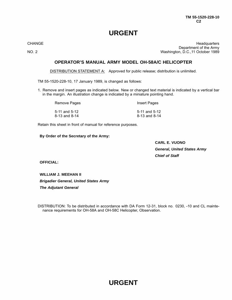
TM 55-1520-228-10C2
URGENTCHANGE
NO. 2
HeadquartersDepartment of the Army
Washington, D.C.,11 October 1989
OPERATOR’S MANUAL ARMY MODEL OH-58A/C HELICOPTER
DISTRIBUTION STATEMENT A: Approved for public release; distribution is unlimited.
TM 55-1520-228-10, 17 January 1989, is changed as follows:
1. Remove and insert pages as indicated below. New or changed text material is indicated by a vertical barin the margin. An illustration change is indicated by a miniature pointing hand.
Remove Pages Insert Pages
5-11 and 5-12 5-11 and 5-128-13 and 8-14 8-13 and 8-14
Retain this sheet in front of manual for reference purposes.
By Order of the Secretary of the Army:
CARL E. VUONO
General, United States Army
Chief of Staff
OFFICIAL:
WILLIAM J. MEEHAN II
Brigadier General, United States Army
The Adjutant General
DISTRIBUTION: To be distributed in accordance with DA Form 12-31, block no. 0230, -10 and CL mainte-nance requirements for OH-58A and OH-58C Helicopter, Observation.
URGENT

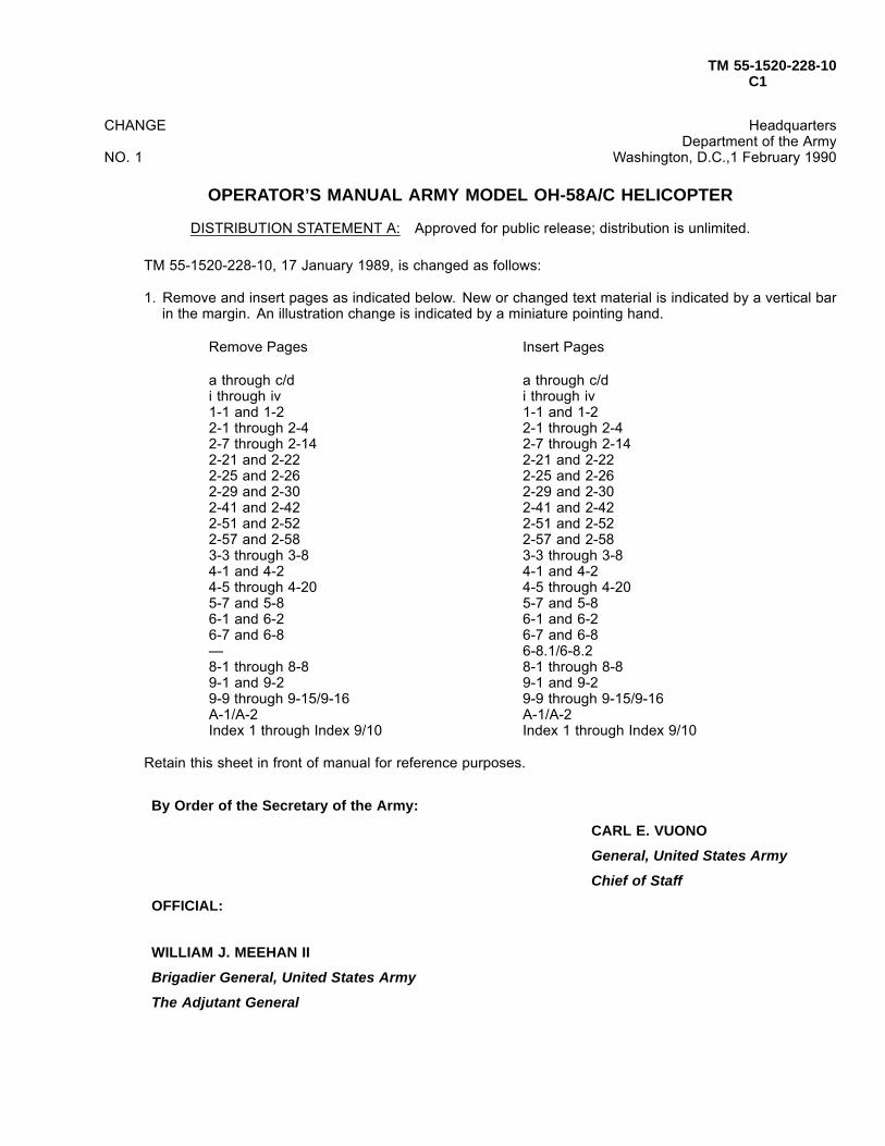
TM 55-1520-228-10C1
CHANGE
NO. 1
HeadquartersDepartment of the Army
Washington, D.C.,1 February 1990
OPERATOR’S MANUAL ARMY MODEL OH-58A/C HELICOPTER
DISTRIBUTION STATEMENT A: Approved for public release; distribution is unlimited.
TM 55-1520-228-10, 17 January 1989, is changed as follows:
1. Remove and insert pages as indicated below. New or changed text material is indicated by a vertical barin the margin. An illustration change is indicated by a miniature pointing hand.
Remove Pages Insert Pages
a through c/d a through c/di through iv i through iv1-1 and 1-2 1-1 and 1-22-1 through 2-4 2-1 through 2-42-7 through 2-14 2-7 through 2-142-21 and 2-22 2-21 and 2-222-25 and 2-26 2-25 and 2-262-29 and 2-30 2-29 and 2-302-41 and 2-42 2-41 and 2-422-51 and 2-52 2-51 and 2-522-57 and 2-58 2-57 and 2-583-3 through 3-8 3-3 through 3-84-1 and 4-2 4-1 and 4-24-5 through 4-20 4-5 through 4-205-7 and 5-8 5-7 and 5-86-1 and 6-2 6-1 and 6-26-7 and 6-8 6-7 and 6-8— 6-8.1/6-8.28-1 through 8-8 8-1 through 8-89-1 and 9-2 9-1 and 9-29-9 through 9-15/9-16 9-9 through 9-15/9-16A-1/A-2 A-1/A-2Index 1 through Index 9/10 Index 1 through Index 9/10
Retain this sheet in front of manual for reference purposes.
By Order of the Secretary of the Army:
CARL E. VUONO
General, United States Army
Chief of Staff
OFFICIAL:
WILLIAM J. MEEHAN II
Brigadier General, United States Army
The Adjutant General

TM 55-1520-228-10C1
DISTRIBUTION: To be distributed in accordance with DA Form 12-31, block no. 0230, -10 and CL mainte-nance requirements for OH-58A and OH-58C Helicopter, Observation.

TM 55-1520-228-10
LIST OF EFFECTIVE PAGES
Dates of issue for original and changed pages are:
��.���� ! ! ! ! ! ! ! ! ! ! ! ! ! ! ! ! ! ! ! ! ! ! ! $) *�����+ $,',2-��.� $ ! ! ! ! ! ! ! ! ! ! ! ! ! ! ! ! ! ! ! ! ! $ 7������+ $,,&2-��.� % ! ! ! ! ! ! ! ! ! ! ! ! ! ! ! ! ! ! ! ! ! $$ ������ $,',2-��.� 8 ! ! ! ! ! ! ! ! ! ! ! ! ! ! ! ! ! ! ! ! ! ! ! ! 9 ���- $,,&2-��.� : ! ! ! ! ! ! ! ! ! ! ! ! ! ! ! ! ! ! ! ! ! ! ! ! 8$ *��+ $,,&2-��.� " ! ! ! ! ! ! ! ! ! ! ! ! ! ! ! ! ! ! ! ! ! ! ! ! %% *��+ $,,$2-��.� 9 ! ! ! ! ! ! ! ! ! ! ! ! ! ! ! ! ! ! ! ! ! ! ! ! $" ����� $,,%2-��.� ) ! ! ! ! ! ! ! ! ! ! ! ! ! ! ! ! ! ! ! ! ! ! ! ! 8& *��� $,,:2-��.� ' ! ! ! ! ! ! ! ! ! ! ! ! ! ! ! ! ! ! ! ! ! ! ! ! %" *��� $,,9
2-��.� , ! ! ! ! ! ! ! ! ! ! ! ! ! ! ! ! ! ! ! ! ! ! ! ! $' *��+ $,,)2-��.� $& ! ! ! ! ! ! ! ! ! ! ! ! ! ! ! ! ! ! ! ! ! ! ! %' *��+ %&&&2-��.� $$ ! ! ! ! ! ! ! ! ! ! ! ! ! ! ! ! ! ! ! ! ! ! ! ! $ ����� %&&82-��.� $% ! ! ! ! ! ! ! ! ! ! ! ! ! ! ! ! ! ! ! ! ! ! ! $& *��� %&&"2-��.� $8 ! ! ! ! ! ! ! ! ! ! ! ! ! ! ! ! ! ! ! ! ! 8& ��.��� %&&"2-��.� $: ! ! ! ! ! ! ! ! ! ! ! ! ! ! ! ! ! ! ! ! ! 8$ ���- %&&92-��.� $" ! ! ! ! ! ! ! ! ! ! ! ! ! ! ! ! ! ! %: ���� ��� %&&)2-��.� $9 ! ! ! ! ! ! ! ! ! ! ! ! ! ! ! ! !;;8& ����� ��� %&&,2-��.� $) ! ! ! ! ! ! ! ! ! ! ! ! ! ! ! ! ! ! ! $, 7������+ %&$&
TOTAL NUMBER OF PAGES IN THIS PUBLICATION IS 266, CONSISTING OF THE FOLLOWING:
Page No. *Change No. Page No. *Change No.
2���� ! ! ! ! ! ! ! ! ! ! ! ! ! ! ! ! ! ! ! ! ! ! ! ! ! ! ! ! ! ! ! ! ! ! ! ! &� ! ! ! ! ! ! ! ! ! ! ! ! ! ! ! ! ! ! ! ! ! ! ! ! ! ! ! ! ! ! ! ! ! ! ! ! ! ! ! $%� ! ! ! ! ! ! ! ! ! ! ! ! ! ! ! ! ! ! ! ! ! ! ! ! ! ! ! ! ! ! ! ! ! ! ! ! ! ! ! $:� ! ! ! ! ! ! ! ! ! ! ! ! ! ! ! ! ! ! ! ! ! ! ! ! ! ! ! ! ! ! ! ! ! ! ! ! ! ! ! $)� ! ! ! ! ! ! ! ! ! ! ! ! ! ! ! ! ! ! ! ! ! ! ! ! ! ! ! ! ! ! ! ! ! ! ! ! ! ! ! $)2 ! ! ! ! ! ! ! ! ! ! ! ! ! ! ! ! ! ! ! ! ! ! ! ! ! ! ! ! ! ! ! ! ! ! ! ! ! ! ! $)� ����5 ! ! ! ! ! ! ! ! ! ! ! ! ! ! ! ! ! ! ! ! ! ! ! ! ! ! ! ! ! ! ! ! ! $)� ! ! ! ! ! ! ! ! ! ! ! ! ! ! ! ! ! ! ! ! ! ! ! ! ! ! ! ! ! ! ! ! ! ! ! ! ! ! ! ! ! ! &�� ! ! ! ! ! ! ! ! ! ! ! ! ! ! ! ! ! ! ! ! ! ! ! ! ! ! ! ! ! ! ! ! ! ! ! ! ! ! ! $'��� ! ! ! ! ! ! ! ! ! ! ! ! ! ! ! ! ! ! ! ! ! ! ! ! ! ! ! ! ! ! ! ! ! ! ! ! ! ! ! $:$#$ ! ! ! ! ! ! ! ! ! ! ! ! ! ! ! ! ! ! ! ! ! ! ! ! ! ! ! ! ! ! ! ! ! ! ! ! ! ! $$$#% ! ! ! ! ! ! ! ! ! ! ! ! ! ! ! ! ! ! ! ! ! ! ! ! ! ! ! ! ! ! ! ! ! ! ! ! ! $&%#$ ! ! ! ! ! ! ! ! ! ! ! ! ! ! ! ! ! ! ! ! ! ! ! ! ! ! ! ! ! ! ! ! ! ! ! ! ! $:%#% ! ! ! ! ! ! ! ! ! ! ! ! ! ! ! ! ! ! ! ! ! ! ! ! ! ! ! ! ! ! ! ! ! ! ! ! ! $%%#8 ! ! ! ! ! ! ! ! ! ! ! ! ! ! ! ! ! ! ! ! ! ! ! ! ! ! ! ! ! ! ! ! ! ! ! ! ! $&%#: ! ! ! ! ! ! ! ! ! ! ! ! ! ! ! ! ! ! ! ! ! ! ! ! ! ! ! ! ! ! ! ! ! ! ! ! ! $:%#" ! ! ! ! ! ! ! ! ! ! ! ! ! ! ! ! ! ! ! ! ! ! ! ! ! ! ! ! ! ! ! ! ! ! ! ! ! $%%#9 ! ! ! ! ! ! ! ! ! ! ! ! ! ! ! ! ! ! ! ! ! ! ! ! ! ! ! ! ! ! ! ! ! ! ! ! ! ! ! &%#) ! ! ! ! ! ! ! ! ! ! ! ! ! ! ! ! ! ! ! ! ! ! ! ! ! ! ! ! ! ! ! ! ! ! ! ! ! $:%#' ! ! ! ! ! ! ! ! ! ! ! ! ! ! ! ! ! ! ! ! ! ! ! ! ! ! ! ! ! ! ! ! ! ! ! ! ! $:%#, ! ! ! ! ! ! ! ! ! ! ! ! ! ! ! ! ! ! ! ! ! ! ! ! ! ! ! ! ! ! ! ! ! ! ! ! ! $&%#$& ! ! ! ! ! ! ! ! ! ! ! ! ! ! ! ! ! ! ! ! ! ! ! ! ! ! ! ! ! ! ! ! ! ! ! ! $:%#$$ ! ! ! ! ! ! ! ! ! ! ! ! ! ! ! ! ! ! ! ! ! ! ! ! ! ! ! ! ! ! ! ! ! ! ! ! $8%#$% ! ! ! ! ! ! ! ! ! ! ! ! ! ! ! ! ! ! ! ! ! ! ! ! ! ! ! ! ! ! ! ! ! ! ! ! $%%#$8 ! ! ! ! ! ! ! ! ! ! ! ! ! ! ! ! ! ! ! ! ! ! ! ! ! ! ! ! ! ! ! ! ! ! ! ! $:%#$: ! ! ! ! ! ! ! ! ! ! ! ! ! ! ! ! ! ! ! ! ! ! ! ! ! ! ! ! ! ! ! ! ! ! ! ! ! ! &%#$" ! ! ! ! ! ! ! ! ! ! ! ! ! ! ! ! ! ! ! ! ! ! ! ! ! ! ! ! ! ! ! ! ! ! ! ! ! ! &%#$9 ! ! ! ! ! ! ! ! ! ! ! ! ! ! ! ! ! ! ! ! ! ! ! ! ! ! ! ! ! ! ! ! ! ! ! ! ! ! &%#$) ! ! ! ! ! ! ! ! ! ! ! ! ! ! ! ! ! ! ! ! ! ! ! ! ! ! ! ! ! ! ! ! ! ! ! ! ! ! &%#$' ! ! ! ! ! ! ! ! ! ! ! ! ! ! ! ! ! ! ! ! ! ! ! ! ! ! ! ! ! ! ! ! ! ! ! ! ! $$%#$, ! ! ! ! ! ! ! ! ! ! ! ! ! ! ! ! ! ! ! ! ! ! ! ! ! ! ! ! ! ! ! ! ! ! ! ! ! $$%#%& ! ! ! ! ! ! ! ! ! ! ! ! ! ! ! ! ! ! ! ! ! ! ! ! ! ! ! ! ! ! ! ! ! ! ! ! ! $$%#%$ ! ! ! ! ! ! ! ! ! ! ! ! ! ! ! ! ! ! ! ! ! ! ! ! ! ! ! ! ! ! ! ! ! ! ! ! $&%#%% ! ! ! ! ! ! ! ! ! ! ! ! ! ! ! ! ! ! ! ! ! ! ! ! ! ! ! ! ! ! ! ! ! ! ! ! ! ! &%#%%!$ ! ! ! ! ! ! ! ! ! ! ! ! ! ! ! ! ! ! ! ! ! ! ! ! ! ! ! ! ! ! ! ! ! ! $&%#%%!% ����5 ! ! ! ! ! ! ! ! ! ! ! ! ! ! ! ! ! ! ! ! ! ! ! ! ! ! ! ! ! !$&%#%8 ! ! ! ! ! ! ! ! ! ! ! ! ! ! ! ! ! ! ! ! ! ! ! ! ! ! ! ! ! ! ! ! ! ! ! ! $:%#%: ! ! ! ! ! ! ! ! ! ! ! ! ! ! ! ! ! ! ! ! ! ! ! ! ! ! ! ! ! ! ! ! ! ! ! ! ! $$%#%" ! ! ! ! ! ! ! ! ! ! ! ! ! ! ! ! ! ! ! ! ! ! ! ! ! ! ! ! ! ! ! ! ! ! ! ! ! ! &
%#%9 ! ! ! ! ! ! ! ! ! ! ! ! ! ! ! ! ! ! ! ! ! ! ! ! ! ! ! ! ! ! ! ! ! ! ! ! ! $$%#%9!$ ! ! ! ! ! ! ! ! ! ! ! ! ! ! ! ! ! ! ! ! ! ! ! ! ! ! ! ! ! ! ! ! ! ! $&%#%9!% ! ! ! ! ! ! ! ! ! ! ! ! ! ! ! ! ! ! ! ! ! ! ! ! ! ! ! ! ! ! ! ! ! ! $&%#%) ! ! ! ! ! ! ! ! ! ! ! ! ! ! ! ! ! ! ! ! ! ! ! ! ! ! ! ! ! ! ! ! ! ! ! ! ! ! &%#%' ! ! ! ! ! ! ! ! ! ! ! ! ! ! ! ! ! ! ! ! ! ! ! ! ! ! ! ! ! ! ! ! ! ! ! ! $%%#%, ! ! ! ! ! ! ! ! ! ! ! ! ! ! ! ! ! ! ! ! ! ! ! ! ! ! ! ! ! ! ! ! ! ! ! ! ! ! &%#8& ! ! ! ! ! ! ! ! ! ! ! ! ! ! ! ! ! ! ! ! ! ! ! ! ! ! ! ! ! ! ! ! ! ! ! ! $:%#8$ ! ! ! ! ! ! ! ! ! ! ! ! ! ! ! ! ! ! ! ! ! ! ! ! ! ! ! ! ! ! ! ! ! ! ! ! $&%#8% ! ! ! ! ! ! ! ! ! ! ! ! ! ! ! ! ! ! ! ! ! ! ! ! ! ! ! ! ! ! ! ! ! ! ! ! $&%#88 ! ! ! ! ! ! ! ! ! ! ! ! ! ! ! ! ! ! ! ! ! ! ! ! ! ! ! ! ! ! ! ! ! ! ! ! ! $$%#8: ! ! ! ! ! ! ! ! ! ! ! ! ! ! ! ! ! ! ! ! ! ! ! ! ! ! ! ! ! ! ! ! ! ! ! ! ! $$%#8" ! ! ! ! ! ! ! ! ! ! ! ! ! ! ! ! ! ! ! ! ! ! ! ! ! ! ! ! ! ! ! ! ! ! ! ! $&%#89 ! ! ! ! ! ! ! ! ! ! ! ! ! ! ! ! ! ! ! ! ! ! ! ! ! ! ! ! ! ! ! ! ! ! ! ! $:%#8) ! ! ! ! ! ! ! ! ! ! ! ! ! ! ! ! ! ! ! ! ! ! ! ! ! ! ! ! ! ! ! ! ! ! ! ! $:%#8' ! ! ! ! ! ! ! ! ! ! ! ! ! ! ! ! ! ! ! ! ! ! ! ! ! ! ! ! ! ! ! ! ! ! ! ! $%%#8, ! ! ! ! ! ! ! ! ! ! ! ! ! ! ! ! ! ! ! ! ! ! ! ! ! ! ! ! ! ! ! ! ! ! ! ! ! ! &%#:& ! ! ! ! ! ! ! ! ! ! ! ! ! ! ! ! ! ! ! ! ! ! ! ! ! ! ! ! ! ! ! ! ! ! ! ! $&%#:$ ! ! ! ! ! ! ! ! ! ! ! ! ! ! ! ! ! ! ! ! ! ! ! ! ! ! ! ! ! ! ! ! ! ! ! ! $&%#:% ! ! ! ! ! ! ! ! ! ! ! ! ! ! ! ! ! ! ! ! ! ! ! ! ! ! ! ! ! ! ! ! ! ! ! ! $&%#:8 ! ! ! ! ! ! ! ! ! ! ! ! ! ! ! ! ! ! ! ! ! ! ! ! ! ! ! ! ! ! ! ! ! ! ! ! $%%#:: ! ! ! ! ! ! ! ! ! ! ! ! ! ! ! ! ! ! ! ! ! ! ! ! ! ! ! ! ! ! ! ! ! ! ! ! $%%#:" ! ! ! ! ! ! ! ! ! ! ! ! ! ! ! ! ! ! ! ! ! ! ! ! ! ! ! ! ! ! ! ! ! ! ! ! ! ! :%#:9 ! ! ! ! ! ! ! ! ! ! ! ! ! ! ! ! ! ! ! ! ! ! ! ! ! ! ! ! ! ! ! ! ! ! ! ! ! ! :%#:9!$ ! ! ! ! ! ! ! ! ! ! ! ! ! ! ! ! ! ! ! ! ! ! ! ! ! ! ! ! ! ! ! ! ! ! ! $$%#:9!% ! ! ! ! ! ! ! ! ! ! ! ! ! ! ! ! ! ! ! ! ! ! ! ! ! ! ! ! ! ! ! ! ! ! $:%#:) ! ! ! ! ! ! ! ! ! ! ! ! ! ! ! ! ! ! ! ! ! ! ! ! ! ! ! ! ! ! ! ! ! ! ! ! ! $$%#:' ! ! ! ! ! ! ! ! ! ! ! ! ! ! ! ! ! ! ! ! ! ! ! ! ! ! ! ! ! ! ! ! ! ! ! ! ! $$%#:, ! ! ! ! ! ! ! ! ! ! ! ! ! ! ! ! ! ! ! ! ! ! ! ! ! ! ! ! ! ! ! ! ! ! ! ! $:%#"& ! ! ! ! ! ! ! ! ! ! ! ! ! ! ! ! ! ! ! ! ! ! ! ! ! ! ! ! ! ! ! ! ! ! ! ! ! ! &%#"$ ! ! ! ! ! ! ! ! ! ! ! ! ! ! ! ! ! ! ! ! ! ! ! ! ! ! ! ! ! ! ! ! ! ! ! ! $:%#"% ! ! ! ! ! ! ! ! ! ! ! ! ! ! ! ! ! ! ! ! ! ! ! ! ! ! ! ! ! ! ! ! ! ! ! ! ! ! )%#"8 ! ! ! ! ! ! ! ! ! ! ! ! ! ! ! ! ! ! ! ! ! ! ! ! ! ! ! ! ! ! ! ! ! ! ! ! ! $$%#": ! ! ! ! ! ! ! ! ! ! ! ! ! ! ! ! ! ! ! ! ! ! ! ! ! ! ! ! ! ! ! ! ! ! ! ! ! ! )%#"" ! ! ! ! ! ! ! ! ! ! ! ! ! ! ! ! ! ! ! ! ! ! ! ! ! ! ! ! ! ! ! ! ! ! ! ! $%%#") ! ! ! ! ! ! ! ! ! ! ! ! ! ! ! ! ! ! ! ! ! ! ! ! ! ! ! ! ! ! ! ! ! ! ! ! ! ! &%#") ! ! ! ! ! ! ! ! ! ! ! ! ! ! ! ! ! ! ! ! ! ! ! ! ! ! ! ! ! ! ! ! ! ! ! ! ! $$%#"' ! ! ! ! ! ! ! ! ! ! ! ! ! ! ! ! ! ! ! ! ! ! ! ! ! ! ! ! ! ! ! ! ! ! ! ! $:%#", ! ! ! ! ! ! ! ! ! ! ! ! ! ! ! ! ! ! ! ! ! ! ! ! ! ! ! ! ! ! ! ! ! ! ! ! ! ! &%#9& ! ! ! ! ! ! ! ! ! ! ! ! ! ! ! ! ! ! ! ! ! ! ! ! ! ! ! ! ! ! ! ! ! ! ! ! $%
*Zero in this column indicates an original page.Change 17 A

TM 55-1520-228-10
LIST OF EFFECTIVE PAGES (Cont)Page No. *Change No. Page No. *Change No.
%#9$ ! ! ! ! ! ! ! ! ! ! ! ! ! ! ! ! ! ! ! ! ! ! ! ! ! ! ! ! ! ! ! ! ! ! ! ! ! $$%#9% ! ! ! ! ! ! ! ! ! ! ! ! ! ! ! ! ! ! ! ! ! ! ! ! ! ! ! ! ! ! ! ! ! ! ! ! ! ! &%#98 ! ! ! ! ! ! ! ! ! ! ! ! ! ! ! ! ! ! ! ! ! ! ! ! ! ! ! ! ! ! ! ! ! ! ! ! $%%#9: ! ! ! ! ! ! ! ! ! ! ! ! ! ! ! ! ! ! ! ! ! ! ! ! ! ! ! ! ! ! ! ! ! ! ! ! $&%#9" ! ! ! ! ! ! ! ! ! ! ! ! ! ! ! ! ! ! ! ! ! ! ! ! ! ! ! ! ! ! ! ! ! ! ! ! $&%#99 ! ! ! ! ! ! ! ! ! ! ! ! ! ! ! ! ! ! ! ! ! ! ! ! ! ! ! ! ! ! ! ! ! ! ! ! ! $$%#9) ! ! ! ! ! ! ! ! ! ! ! ! ! ! ! ! ! ! ! ! ! ! ! ! ! ! ! ! ! ! ! ! ! ! ! ! $&%#9' ����5 ! ! ! ! ! ! ! ! ! ! ! ! ! ! ! ! ! ! ! ! ! ! ! ! ! ! ! ! ! ! ! ! !&8#$ ! ! ! ! ! ! ! ! ! ! ! ! ! ! ! ! ! ! ! ! ! ! ! ! ! ! ! ! ! ! ! ! ! ! ! ! ! ! $$8#% ! ! ! ! ! ! ! ! ! ! ! ! ! ! ! ! ! ! ! ! ! ! ! ! ! ! ! ! ! ! ! ! ! ! ! ! ! $&8#8 ! ! ! ! ! ! ! ! ! ! ! ! ! ! ! ! ! ! ! ! ! ! ! ! ! ! ! ! ! ! ! ! ! ! ! ! ! $:8#: ! ! ! ! ! ! ! ! ! ! ! ! ! ! ! ! ! ! ! ! ! ! ! ! ! ! ! ! ! ! ! ! ! ! ! ! ! $:8#" ! ! ! ! ! ! ! ! ! ! ! ! ! ! ! ! ! ! ! ! ! ! ! ! ! ! ! ! ! ! ! ! ! ! ! ! ! ! $$8#9 ! ! ! ! ! ! ! ! ! ! ! ! ! ! ! ! ! ! ! ! ! ! ! ! ! ! ! ! ! ! ! ! ! ! ! ! ! ! ! &8#) ! ! ! ! ! ! ! ! ! ! ! ! ! ! ! ! ! ! ! ! ! ! ! ! ! ! ! ! ! ! ! ! ! ! ! ! ! $&8#' ! ! ! ! ! ! ! ! ! ! ! ! ! ! ! ! ! ! ! ! ! ! ! ! ! ! ! ! ! ! ! ! ! ! ! ! ! ! $$8#'!% ! ! ! ! ! ! ! ! ! ! ! ! ! ! ! ! ! ! ! ! ! ! ! ! ! ! ! ! ! ! ! ! ! ! ! ! $$8#'!% ! ! ! ! ! ! ! ! ! ! ! ! ! ! ! ! ! ! ! ! ! ! ! ! ! ! ! ! ! ! ! ! ! ! ! ! $$8#'!8 ! ! ! ! ! ! ! ! ! ! ! ! ! ! ! ! ! ! ! ! ! ! ! ! ! ! ! ! ! ! ! ! ! ! ! ! $$8#'!: ! ! ! ! ! ! ! ! ! ! ! ! ! ! ! ! ! ! ! ! ! ! ! ! ! ! ! ! ! ! ! ! ! ! ! ! ! &8#, ! ! ! ! ! ! ! ! ! ! ! ! ! ! ! ! ! ! ! ! ! ! ! ! ! ! ! ! ! ! ! ! ! ! ! ! ! ! ! &8#$& ! ! ! ! ! ! ! ! ! ! ! ! ! ! ! ! ! ! ! ! ! ! ! ! ! ! ! ! ! ! ! ! ! ! ! ! ! ! &8#$$ ! ! ! ! ! ! ! ! ! ! ! ! ! ! ! ! ! ! ! ! ! ! ! ! ! ! ! ! ! ! ! ! ! ! ! ! ! $$8#$% ! ! ! ! ! ! ! ! ! ! ! ! ! ! ! ! ! ! ! ! ! ! ! ! ! ! ! ! ! ! ! ! ! ! ! ! ! $$8#$8 ! ! ! ! ! ! ! ! ! ! ! ! ! ! ! ! ! ! ! ! ! ! ! ! ! ! ! ! ! ! ! ! ! ! ! ! ! $$8#$: ! ! ! ! ! ! ! ! ! ! ! ! ! ! ! ! ! ! ! ! ! ! ! ! ! ! ! ! ! ! ! ! ! ! ! ! ! $$8#$" ! ! ! ! ! ! ! ! ! ! ! ! ! ! ! ! ! ! ! ! ! ! ! ! ! ! ! ! ! ! ! ! ! ! ! ! ! ! &8#$9 ! ! ! ! ! ! ! ! ! ! ! ! ! ! ! ! ! ! ! ! ! ! ! ! ! ! ! ! ! ! ! ! ! ! ! ! ! ! &8#$) ! ! ! ! ! ! ! ! ! ! ! ! ! ! ! ! ! ! ! ! ! ! ! ! ! ! ! ! ! ! ! ! ! ! ! ! ! $$8#$' ! ! ! ! ! ! ! ! ! ! ! ! ! ! ! ! ! ! ! ! ! ! ! ! ! ! ! ! ! ! ! ! ! ! ! ! ! $$8#$, ! ! ! ! ! ! ! ! ! ! ! ! ! ! ! ! ! ! ! ! ! ! ! ! ! ! ! ! ! ! ! ! ! ! ! ! ! $$8#%& ! ! ! ! ! ! ! ! ! ! ! ! ! ! ! ! ! ! ! ! ! ! ! ! ! ! ! ! ! ! ! ! ! ! ! ! ! $$8#%$ ! ! ! ! ! ! ! ! ! ! ! ! ! ! ! ! ! ! ! ! ! ! ! ! ! ! ! ! ! ! ! ! ! ! ! ! ! ! &8#%% ! ! ! ! ! ! ! ! ! ! ! ! ! ! ! ! ! ! ! ! ! ! ! ! ! ! ! ! ! ! ! ! ! ! ! ! ! ! &8#%8 ! ! ! ! ! ! ! ! ! ! ! ! ! ! ! ! ! ! ! ! ! ! ! ! ! ! ! ! ! ! ! ! ! ! ! ! ! $$8#%: ! ! ! ! ! ! ! ! ! ! ! ! ! ! ! ! ! ! ! ! ! ! ! ! ! ! ! ! ! ! ! ! ! ! ! ! ! $$8#%:!$ ! ! ! ! ! ! ! ! ! ! ! ! ! ! ! ! ! ! ! ! ! ! ! ! ! ! ! ! ! ! ! ! ! ! ! $$8#%:!% ����5 ! ! ! ! ! ! ! ! ! ! ! ! ! ! ! ! ! ! ! ! ! ! ! ! ! ! ! ! ! !$$8#%" ! ! ! ! ! ! ! ! ! ! ! ! ! ! ! ! ! ! ! ! ! ! ! ! ! ! ! ! ! ! ! ! ! ! ! ! ! ! &8#%9 ! ! ! ! ! ! ! ! ! ! ! ! ! ! ! ! ! ! ! ! ! ! ! ! ! ! ! ! ! ! ! ! ! ! ! ! ! ! &8#%) ! ! ! ! ! ! ! ! ! ! ! ! ! ! ! ! ! ! ! ! ! ! ! ! ! ! ! ! ! ! ! ! ! ! ! ! ! $$8#%' ! ! ! ! ! ! ! ! ! ! ! ! ! ! ! ! ! ! ! ! ! ! ! ! ! ! ! ! ! ! ! ! ! ! ! ! ! ! &8#%, ! ! ! ! ! ! ! ! ! ! ! ! ! ! ! ! ! ! ! ! ! ! ! ! ! ! ! ! ! ! ! ! ! ! ! ! $&8#8& ! ! ! ! ! ! ! ! ! ! ! ! ! ! ! ! ! ! ! ! ! ! ! ! ! ! ! ! ! ! ! ! ! ! ! ! ! ! &8#8$ ! ! ! ! ! ! ! ! ! ! ! ! ! ! ! ! ! ! ! ! ! ! ! ! ! ! ! ! ! ! ! ! ! ! ! ! ! $$8#8% ! ! ! ! ! ! ! ! ! ! ! ! ! ! ! ! ! ! ! ! ! ! ! ! ! ! ! ! ! ! ! ! ! ! ! ! ! $$8#8%!$ ! ! ! ! ! ! ! ! ! ! ! ! ! ! ! ! ! ! ! ! ! ! ! ! ! ! ! ! ! ! ! ! ! ! ! $$8#8%!% ! ! ! ! ! ! ! ! ! ! ! ! ! ! ! ! ! ! ! ! ! ! ! ! ! ! ! ! ! ! ! ! ! ! ! $$����5 ! ! ! ! ! ! ! ! ! ! ! ! ! ! ! ! ! ! ! ! ! ! ! ! ! ! ! ! ! ! ! ! ! ! ! ! !$$8#8%!8 ! ! ! ! ! ! ! ! ! ! ! ! ! ! ! ! ! ! ! ! ! ! ! ! ! ! ! ! ! ! ! ! ! ! ! $$8#88 ! ! ! ! ! ! ! ! ! ! ! ! ! ! ! ! ! ! ! ! ! ! ! ! ! ! ! ! ! ! ! ! ! ! ! ! ! $$8#8: ! ! ! ! ! ! ! ! ! ! ! ! ! ! ! ! ! ! ! ! ! ! ! ! ! ! ! ! ! ! ! ! ! ! ! ! $&8#8" ! ! ! ! ! ! ! ! ! ! ! ! ! ! ! ! ! ! ! ! ! ! ! ! ! ! ! ! ! ! ! ! ! ! ! ! ! $$8#89 ! ! ! ! ! ! ! ! ! ! ! ! ! ! ! ! ! ! ! ! ! ! ! ! ! ! ! ! ! ! ! ! ! ! ! ! ! ! &
8#8) ! ! ! ! ! ! ! ! ! ! ! ! ! ! ! ! ! ! ! ! ! ! ! ! ! ! ! ! ! ! ! ! ! ! ! ! ! ! &8#8' ����5 ! ! ! ! ! ! ! ! ! ! ! ! ! ! ! ! ! ! ! ! ! ! ! ! ! ! ! ! ! ! ! ! !&:#$ ! ! ! ! ! ! ! ! ! ! ! ! ! ! ! ! ! ! ! ! ! ! ! ! ! ! ! ! ! ! ! ! ! ! ! ! ! $&:#% ����5 ! ! ! ! ! ! ! ! ! ! ! ! ! ! ! ! ! ! ! ! ! ! ! ! ! ! ! ! ! ! ! ! ! &"#$ ! ! ! ! ! ! ! ! ! ! ! ! ! ! ! ! ! ! ! ! ! ! ! ! ! ! ! ! ! ! ! ! ! ! ! ! ! $:"#% ! ! ! ! ! ! ! ! ! ! ! ! ! ! ! ! ! ! ! ! ! ! ! ! ! ! ! ! ! ! ! ! ! ! ! ! ! ! $$����5 ! ! ! ! ! ! ! ! ! ! ! ! ! ! ! ! ! ! ! ! ! ! ! ! ! ! ! ! ! ! ! ! ! ! ! ! ! !&"#8 ! ! ! ! ! ! ! ! ! ! ! ! ! ! ! ! ! ! ! ! ! ! ! ! ! ! ! ! ! ! ! ! ! ! ! ! ! $:"#" ! ! ! ! ! ! ! ! ! ! ! ! ! ! ! ! ! ! ! ! ! ! ! ! ! ! ! ! ! ! ! ! ! ! ! ! ! $:"#9 ! ! ! ! ! ! ! ! ! ! ! ! ! ! ! ! ! ! ! ! ! ! ! ! ! ! ! ! ! ! ! ! ! ! ! ! ! $:"#) ! ! ! ! ! ! ! ! ! ! ! ! ! ! ! ! ! ! ! ! ! ! ! ! ! ! ! ! ! ! ! ! ! ! ! ! ! $""#' ! ! ! ! ! ! ! ! ! ! ! ! ! ! ! ! ! ! ! ! ! ! ! ! ! ! ! ! ! ! ! ! ! ! ! ! ! $&"#, ! ! ! ! ! ! ! ! ! ! ! ! ! ! ! ! ! ! ! ! ! ! ! ! ! ! ! ! ! ! ! ! ! ! ! ! ! ! $$"#$& ! ! ! ! ! ! ! ! ! ! ! ! ! ! ! ! ! ! ! ! ! ! ! ! ! ! ! ! ! ! ! ! ! ! ! ! $:"#$$ ! ! ! ! ! ! ! ! ! ! ! ! ! ! ! ! ! ! ! ! ! ! ! ! ! ! ! ! ! ! ! ! ! ! ! ! ! ! %"#$% ! ! ! ! ! ! ! ! ! ! ! ! ! ! ! ! ! ! ! ! ! ! ! ! ! ! ! ! ! ! ! ! ! ! ! ! $:9#$ ! ! ! ! ! ! ! ! ! ! ! ! ! ! ! ! ! ! ! ! ! ! ! ! ! ! ! ! ! ! ! ! ! ! ! ! ! ! $$9#% ! ! ! ! ! ! ! ! ! ! ! ! ! ! ! ! ! ! ! ! ! ! ! ! ! ! ! ! ! ! ! ! ! ! ! ! ! $:9#8 ! ! ! ! ! ! ! ! ! ! ! ! ! ! ! ! ! ! ! ! ! ! ! ! ! ! ! ! ! ! ! ! ! ! ! ! ! ! $$9#: ! ! ! ! ! ! ! ! ! ! ! ! ! ! ! ! ! ! ! ! ! ! ! ! ! ! ! ! ! ! ! ! ! ! ! ! ! $&9#" ! ! ! ! ! ! ! ! ! ! ! ! ! ! ! ! ! ! ! ! ! ! ! ! ! ! ! ! ! ! ! ! ! ! ! ! ! ! $$9#9 ! ! ! ! ! ! ! ! ! ! ! ! ! ! ! ! ! ! ! ! ! ! ! ! ! ! ! ! ! ! ! ! ! ! ! ! ! ! ! &9#) ! ! ! ! ! ! ! ! ! ! ! ! ! ! ! ! ! ! ! ! ! ! ! ! ! ! ! ! ! ! ! ! ! ! ! ! ! ! $$9#' ����5 ! ! ! ! ! ! ! ! ! ! ! ! ! ! ! ! ! ! ! ! ! ! ! ! ! ! ! ! ! ! ! ! ! !&9#'!$ ! ! ! ! ! ! ! ! ! ! ! ! ! ! ! ! ! ! ! ! ! ! ! ! ! ! ! ! ! ! ! ! ! ! ! ! ! $9#'!% ����5 ! ! ! ! ! ! ! ! ! ! ! ! ! ! ! ! ! ! ! ! ! ! ! ! ! ! ! ! ! ! ! !$9#, ! ! ! ! ! ! ! ! ! ! ! ! ! ! ! ! ! ! ! ! ! ! ! ! ! ! ! ! ! ! ! ! ! ! ! ! ! $&9#$& ����5 ! ! ! ! ! ! ! ! ! ! ! ! ! ! ! ! ! ! ! ! ! ! ! ! ! ! ! ! ! ! ! ! !&)#$ ! ! ! ! ! ! ! ! ! ! ! ! ! ! ! ! ! ! ! ! ! ! ! ! ! ! ! ! ! ! ! ! ! ! ! ! ! ! $$)#% ! ! ! ! ! ! ! ! ! ! ! ! ! ! ! ! ! ! ! ! ! ! ! ! ! ! ! ! ! ! ! ! ! ! ! ! ! ! $$)#: ! ! ! ! ! ! ! ! ! ! ! ! ! ! ! ! ! ! ! ! ! ! ! ! ! ! ! ! ! ! ! ! ! ! ! ! ! ! ! &)#9 ! ! ! ! ! ! ! ! ! ! ! ! ! ! ! ! ! ! ! ! ! ! ! ! ! ! ! ! ! ! ! ! ! ! ! ! ! ! $$)#9 ! ! ! ! ! ! ! ! ! ! ! ! ! ! ! ! ! ! ! ! ! ! ! ! ! ! ! ! ! ! ! ! ! ! ! ! ! ! ! &)#) ! ! ! ! ! ! ! ! ! ! ! ! ! ! ! ! ! ! ! ! ! ! ! ! ! ! ! ! ! ! ! ! ! ! ! ! ! ! ! &)#' ! ! ! ! ! ! ! ! ! ! ! ! ! ! ! ! ! ! ! ! ! ! ! ! ! ! ! ! ! ! ! ! ! ! ! ! ! ! ! &)#:) ! ! ! ! ! ! ! ! ! ! ! ! ! ! ! ! ! ! ! ! ! ! ! ! ! ! ! ! ! ! ! ! ! ! ! ! ! ! &)#:' ! ! ! ! ! ! ! ! ! ! ! ! ! ! ! ! ! ! ! ! ! ! ! ! ! ! ! ! ! ! ! ! ! ! ! ! ! ! &)#:, ! ! ! ! ! ! ! ! ! ! ! ! ! ! ! ! ! ! ! ! ! ! ! ! ! ! ! ! ! ! ! ! ! ! ! ! ! ! &)#"& ! ! ! ! ! ! ! ! ! ! ! ! ! ! ! ! ! ! ! ! ! ! ! ! ! ! ! ! ! ! ! ! ! ! ! ! ! ! &)#"$ ! ! ! ! ! ! ! ! ! ! ! ! ! ! ! ! ! ! ! ! ! ! ! ! ! ! ! ! ! ! ! ! ! ! ! ! ! ! &)#"% ! ! ! ! ! ! ! ! ! ! ! ! ! ! ! ! ! ! ! ! ! ! ! ! ! ! ! ! ! ! ! ! ! ! ! ! ! ! &)#"8 ! ! ! ! ! ! ! ! ! ! ! ! ! ! ! ! ! ! ! ! ! ! ! ! ! ! ! ! ! ! ! ! ! ! ! ! ! ! &)#": ! ! ! ! ! ! ! ! ! ! ! ! ! ! ! ! ! ! ! ! ! ! ! ! ! ! ! ! ! ! ! ! ! ! ! ! ! ! &)#"" ! ! ! ! ! ! ! ! ! ! ! ! ! ! ! ! ! ! ! ! ! ! ! ! ! ! ! ! ! ! ! ! ! ! ! ! ! ! &)#"9 ! ! ! ! ! ! ! ! ! ! ! ! ! ! ! ! ! ! ! ! ! ! ! ! ! ! ! ! ! ! ! ! ! ! ! ! ! ! &)#") ! ! ! ! ! ! ! ! ! ! ! ! ! ! ! ! ! ! ! ! ! ! ! ! ! ! ! ! ! ! ! ! ! ! ! ! ! ! &)#"' ! ! ! ! ! ! ! ! ! ! ! ! ! ! ! ! ! ! ! ! ! ! ! ! ! ! ! ! ! ! ! ! ! ! ! ! ! ! &)#", ! ! ! ! ! ! ! ! ! ! ! ! ! ! ! ! ! ! ! ! ! ! ! ! ! ! ! ! ! ! ! ! ! ! ! ! ! ! &)#9& ! ! ! ! ! ! ! ! ! ! ! ! ! ! ! ! ! ! ! ! ! ! ! ! ! ! ! ! ! ! ! ! ! ! ! ! ! ! &)#9$ ! ! ! ! ! ! ! ! ! ! ! ! ! ! ! ! ! ! ! ! ! ! ! ! ! ! ! ! ! ! ! ! ! ! ! ! ! $$)#98 ! ! ! ! ! ! ! ! ! ! ! ! ! ! ! ! ! ! ! ! ! ! ! ! ! ! ! ! ! ! ! ! ! ! ! ! ! ! &)#9: ! ! ! ! ! ! ! ! ! ! ! ! ! ! ! ! ! ! ! ! ! ! ! ! ! ! ! ! ! ! ! ! ! ! ! ! ! ! &)#9" ! ! ! ! ! ! ! ! ! ! ! ! ! ! ! ! ! ! ! ! ! ! ! ! ! ! ! ! ! ! ! ! ! ! ! ! ! ! &)#99 ! ! ! ! ! ! ! ! ! ! ! ! ! ! ! ! ! ! ! ! ! ! ! ! ! ! ! ! ! ! ! ! ! ! ! ! ! ! &
*Zero in this column indicates an original page.B Change 17

TM 55-1520-228-10
LIST OF EFFECTIVE PAGES (Cont)Page No. *Change No. Page No. *Change No.
)#9) ! ! ! ! ! ! ! ! ! ! ! ! ! ! ! ! ! ! ! ! ! ! ! ! ! ! ! ! ! ! ! ! ! ! ! ! ! ! &)#9' ! ! ! ! ! ! ! ! ! ! ! ! ! ! ! ! ! ! ! ! ! ! ! ! ! ! ! ! ! ! ! ! ! ! ! ! ! ! &)#9, ! ! ! ! ! ! ! ! ! ! ! ! ! ! ! ! ! ! ! ! ! ! ! ! ! ! ! ! ! ! ! ! ! ! ! ! ! ! &)#)& ! ! ! ! ! ! ! ! ! ! ! ! ! ! ! ! ! ! ! ! ! ! ! ! ! ! ! ! ! ! ! ! ! ! ! ! ! ! &)#)$ ! ! ! ! ! ! ! ! ! ! ! ! ! ! ! ! ! ! ! ! ! ! ! ! ! ! ! ! ! ! ! ! ! ! ! ! ! ! &)#)% ! ! ! ! ! ! ! ! ! ! ! ! ! ! ! ! ! ! ! ! ! ! ! ! ! ! ! ! ! ! ! ! ! ! ! ! ! ! &)#)8 ! ! ! ! ! ! ! ! ! ! ! ! ! ! ! ! ! ! ! ! ! ! ! ! ! ! ! ! ! ! ! ! ! ! ! ! ! ! &)#): ! ! ! ! ! ! ! ! ! ! ! ! ! ! ! ! ! ! ! ! ! ! ! ! ! ! ! ! ! ! ! ! ! ! ! ! ! ! &)#)" ! ! ! ! ! ! ! ! ! ! ! ! ! ! ! ! ! ! ! ! ! ! ! ! ! ! ! ! ! ! ! ! ! ! ! ! ! ! &)#)9 ! ! ! ! ! ! ! ! ! ! ! ! ! ! ! ! ! ! ! ! ! ! ! ! ! ! ! ! ! ! ! ! ! ! ! ! ! ! &)#)) ! ! ! ! ! ! ! ! ! ! ! ! ! ! ! ! ! ! ! ! ! ! ! ! ! ! ! ! ! ! ! ! ! ! ! ! $&)#)' ! ! ! ! ! ! ! ! ! ! ! ! ! ! ! ! ! ! ! ! ! ! ! ! ! ! ! ! ! ! ! ! ! ! ! ! $&)#), ! ! ! ! ! ! ! ! ! ! ! ! ! ! ! ! ! ! ! ! ! ! ! ! ! ! ! ! ! ! ! ! ! ! ! ! ! ! &)#'& ! ! ! ! ! ! ! ! ! ! ! ! ! ! ! ! ! ! ! ! ! ! ! ! ! ! ! ! ! ! ! ! ! ! ! ! $%)#'$ ! ! ! ! ! ! ! ! ! ! ! ! ! ! ! ! ! ! ! ! ! ! ! ! ! ! ! ! ! ! ! ! ! ! ! ! ! ! &)#'% ! ! ! ! ! ! ! ! ! ! ! ! ! ! ! ! ! ! ! ! ! ! ! ! ! ! ! ! ! ! ! ! ! ! ! ! $")#'8 ! ! ! ! ! ! ! ! ! ! ! ! ! ! ! ! ! ! ! ! ! ! ! ! ! ! ! ! ! ! ! ! ! ! ! ! $")#': ����5 ! ! ! ! ! ! ! ! ! ! ! ! ! ! ! ! ! ! ! ! ! ! ! ! ! ! ! ! ! ! ! !!&'#$ ! ! ! ! ! ! ! ! ! ! ! ! ! ! ! ! ! ! ! ! ! ! ! ! ! ! ! ! ! ! ! ! ! ! ! ! ! ! ! &'#% ! ! ! ! ! ! ! ! ! ! ! ! ! ! ! ! ! ! ! ! ! ! ! ! ! ! ! ! ! ! ! ! ! ! ! ! ! ! $$'#8 ! ! ! ! ! ! ! ! ! ! ! ! ! ! ! ! ! ! ! ! ! ! ! ! ! ! ! ! ! ! ! ! ! ! ! ! ! ! $$'#: ! ! ! ! ! ! ! ! ! ! ! ! ! ! ! ! ! ! ! ! ! ! ! ! ! ! ! ! ! ! ! ! ! ! ! ! ! $&'#" ! ! ! ! ! ! ! ! ! ! ! ! ! ! ! ! ! ! ! ! ! ! ! ! ! ! ! ! ! ! ! ! ! ! ! ! ! $:'#9 ! ! ! ! ! ! ! ! ! ! ! ! ! ! ! ! ! ! ! ! ! ! ! ! ! ! ! ! ! ! ! ! ! ! ! ! ! ! $$'#) ! ! ! ! ! ! ! ! ! ! ! ! ! ! ! ! ! ! ! ! ! ! ! ! ! ! ! ! ! ! ! ! ! ! ! ! ! $:'#' ! ! ! ! ! ! ! ! ! ! ! ! ! ! ! ! ! ! ! ! ! ! ! ! ! ! ! ! ! ! ! ! ! ! ! ! ! $"'#, ! ! ! ! ! ! ! ! ! ! ! ! ! ! ! ! ! ! ! ! ! ! ! ! ! ! ! ! ! ! ! ! ! ! ! ! ! ! $$'#$& ! ! ! ! ! ! ! ! ! ! ! ! ! ! ! ! ! ! ! ! ! ! ! ! ! ! ! ! ! ! ! ! ! ! ! ! ! $$'#$$ ! ! ! ! ! ! ! ! ! ! ! ! ! ! ! ! ! ! ! ! ! ! ! ! ! ! ! ! ! ! ! ! ! ! ! ! $:
'#$% ! ! ! ! ! ! ! ! ! ! ! ! ! ! ! ! ! ! ! ! ! ! ! ! ! ! ! ! ! ! ! ! ! ! ! ! $:'#$8 ! ! ! ! ! ! ! ! ! ! ! ! ! ! ! ! ! ! ! ! ! ! ! ! ! ! ! ! ! ! ! ! ! ! ! ! $:'#$: ! ! ! ! ! ! ! ! ! ! ! ! ! ! ! ! ! ! ! ! ! ! ! ! ! ! ! ! ! ! ! ! ! ! ! ! $:'#$" ! ! ! ! ! ! ! ! ! ! ! ! ! ! ! ! ! ! ! ! ! ! ! ! ! ! ! ! ! ! ! ! ! ! ! ! ! $$'#$9 ! ! ! ! ! ! ! ! ! ! ! ! ! ! ! ! ! ! ! ! ! ! ! ! ! ! ! ! ! ! ! ! ! ! ! ! $&'#$) ! ! ! ! ! ! ! ! ! ! ! ! ! ! ! ! ! ! ! ! ! ! ! ! ! ! ! ! ! ! ! ! ! ! ! ! ! $$'#$' ����5 ! ! ! ! ! ! ! ! ! ! ! ! ! ! ! ! ! ! ! ! ! ! ! ! ! ! ! ! ! ! ! ! !&,#$ ! ! ! ! ! ! ! ! ! ! ! ! ! ! ! ! ! ! ! ! ! ! ! ! ! ! ! ! ! ! ! ! ! ! ! ! ! $:,#% ! ! ! ! ! ! ! ! ! ! ! ! ! ! ! ! ! ! ! ! ! ! ! ! ! ! ! ! ! ! ! ! ! ! ! ! ! $:,#8 ! ! ! ! ! ! ! ! ! ! ! ! ! ! ! ! ! ! ! ! ! ! ! ! ! ! ! ! ! ! ! ! ! ! ! ! ! $:,#: ! ! ! ! ! ! ! ! ! ! ! ! ! ! ! ! ! ! ! ! ! ! ! ! ! ! ! ! ! ! ! ! ! ! ! ! ! ! ! &,#" ! ! ! ! ! ! ! ! ! ! ! ! ! ! ! ! ! ! ! ! ! ! ! ! ! ! ! ! ! ! ! ! ! ! ! ! ! $:,#9 ! ! ! ! ! ! ! ! ! ! ! ! ! ! ! ! ! ! ! ! ! ! ! ! ! ! ! ! ! ! ! ! ! ! ! ! ! $",#) ! ! ! ! ! ! ! ! ! ! ! ! ! ! ! ! ! ! ! ! ! ! ! ! ! ! ! ! ! ! ! ! ! ! ! ! ! $),#' ! ! ! ! ! ! ! ! ! ! ! ! ! ! ! ! ! ! ! ! ! ! ! ! ! ! ! ! ! ! ! ! ! ! ! ! ! $),#, ! ! ! ! ! ! ! ! ! ! ! ! ! ! ! ! ! ! ! ! ! ! ! ! ! ! ! ! ! ! ! ! ! ! ! ! ! $:,#$& ! ! ! ! ! ! ! ! ! ! ! ! ! ! ! ! ! ! ! ! ! ! ! ! ! ! ! ! ! ! ! ! ! ! ! ! $:,#$$ ! ! ! ! ! ! ! ! ! ! ! ! ! ! ! ! ! ! ! ! ! ! ! ! ! ! ! ! ! ! ! ! ! ! ! ! $:,#$% ! ! ! ! ! ! ! ! ! ! ! ! ! ! ! ! ! ! ! ! ! ! ! ! ! ! ! ! ! ! ! ! ! ! ! ! $:,#$8 ! ! ! ! ! ! ! ! ! ! ! ! ! ! ! ! ! ! ! ! ! ! ! ! ! ! ! ! ! ! ! ! ! ! ! ! $:,#$: ����5 ! ! ! ! ! ! ! ! ! ! ! ! ! ! ! ! ! ! ! ! ! ! ! ! ! ! ! ! ! ! ! ! &�#$ ! ! ! ! ! ! ! ! ! ! ! ! ! ! ! ! ! ! ! ! ! ! ! ! ! ! ! ! ! ! ! ! ! ! ! ! ! $"�#% ����5 ! ! ! ! ! ! ! ! ! ! ! ! ! ! ! ! ! ! ! ! ! ! ! ! ! ! ! ! ! ! ! ! ! &�#$ ! ! ! ! ! ! ! ! ! ! ! ! ! ! ! ! ! ! ! ! ! ! ! ! ! ! ! ! ! ! ! ! ! ! ! ! ! $'�#% ����5 ! ! ! ! ! ! ! ! ! ! ! ! ! ! ! ! ! ! ! ! ! ! ! ! ! ! ! ! ! ! ! ! ! &<������+#$ ! ! ! ! ! ! ! ! ! ! ! ! ! ! ! ! ! ! ! ! ! ! ! ! ! ! ! ! ! ! ! ! &<������+#% ! ! ! ! ! ! ! ! ! ! ! ! ! ! ! ! ! ! ! ! ! ! ! ! ! ! ! ! ! ! $"����0#$ ! ! ! ! ! ! ! ! ! ! ! ! ! ! ! ! ! ! ! ! ! ! ! ! ! ! ! ! ! ! ! ! ! ! ! &����0#% ����5 ! ! ! ! ! ! ! ! ! ! ! ! ! ! ! ! ! ! ! ! ! ! ! ! ! ! ! ! ! &
*Zero in this column indicates an original page.Change 17 C/(D Blank)

* TM 55-1520-228-10
TECHNICAL MANUAL U.S. ARMY AVIATIONAND MISSILE COMMAND
No. 55-1520-228-10 17 JANUARY 1989
OPERATOR’S MANUALARMY MODEL OH-58 A/C
HELICOPTER
REPORTING ERRORS AND RECOMMENDING IMPROVEMENTSREPORTING OF ERRORS AND RECOMMENDING IMPROVEMENTS You can improve thismanual. If you f nd any mistakes or if you know of a way to improve these procedures, please letus know. Mail your letter or DA Form 2028 (Recommended Changes to Publications and BlankForms), located in the back of this manual, directly to: Commander, U.S. Army Aviation andMissile Command, ATTN: AMSAM-MMC-MA-NP, Redstone Arsenal, AL 35898-5000. A reply willbe furnished to you. You may also send in your comments electronically to our E-mail address:[email protected] or by fax 256-842-6546/DSN 788-6546. For the World Wide Web use:https://amcom2028.redstone.army.mil. Instructions for sending an electronic 2028 may be foundat the back of this manual immediately preceding the hard copy 2028.
TABLE OF CONTENTSPage
CHAPTER 1 INTRODUCTION . . . . . . . . . . . . . . . . . . . . . . . . . . . . . . . . . . . . . . . . . . . . . . . . . . . . . . . . . . . . . . . 1-1CHAPTER 2 HELICOPTER AND SYSTEMS DESCRIPTION
AND OPERATIONS . . . . . . . . . . . . . . . . . . . . . . . . . . . . . . . . . . . . . . . . . . . . . . . . . . . . . . . . . . . . . 2-1Section I HELICOPTER . . . . . . . . . . . . . . . . . . . . . . . . . . . . . . . . . . . . . . . . . . . . . . . . . . . . . . . . . . . . . . . . 2-1Section II EMERGENCY EQUIPMENT . . . . . . . . . . . . . . . . . . . . . . . . . . . . . . . . . . . . . . . . . . . . . . . . . . . 2-18Section III ENGINES AND RELATED SYSTEMS . . . . . . . . . . . . . . . . . . . . . . . . . . . . . . . . . . . . . . . . . . 2-18Section IV FUEL SYSTEM . . . . . . . . . . . . . . . . . . . . . . . . . . . . . . . . . . . . . . . . . . . . . . . . . . . . . . . . . . . . . . . 2-28Section V FLIGHT CONTROLS . . . . . . . . . . . . . . . . . . . . . . . . . . . . . . . . . . . . . . . . . . . . . . . . . . . . . . . . . . 2-30Section VI HYDRAULIC SYSTEM . . . . . . . . . . . . . . . . . . . . . . . . . . . . . . . . . . . . . . . . . . . . . . . . . . . . . . . . 2-32Section VII POWER TRAIN SYSTEM . . . . . . . . . . . . . . . . . . . . . . . . . . . . . . . . . . . . . . . . . . . . . . . . . . . . . 2-33Section VIII MAIN AND TAIL ROTOR GROUPS . . . . . . . . . . . . . . . . . . . . . . . . . . . . . . . . . . . . . . . . . . . . 2-34Section IX UTILITY SYSTEM . . . . . . . . . . . . . . . . . . . . . . . . . . . . . . . . . . . . . . . . . . . . . . . . . . . . . . . . . . . . 2-35Section X HEATING AND VENTILATION . . . . . . . . . . . . . . . . . . . . . . . . . . . . . . . . . . . . . . . . . . . . . . . . . 2-35Section XI ELECTRICAL POWER SUPPLY AND DISTRIBUTION SYSTEM . . . . . . . . . . . . . . . . . . 2-40Section XII LIGHTING . . . . . . . . . . . . . . . . . . . . . . . . . . . . . . . . . . . . . . . . . . . . . . . . . . . . . . . . . . . . . . . . . . . 2-43Section XIII FLIGHT INSTRUMENTS . . . . . . . . . . . . . . . . . . . . . . . . . . . . . . . . . . . . . . . . . . . . . . . . . . . . . . 2-45Section XIV SERVICING, PARKING, AND MOORING . . . . . . . . . . . . . . . . . . . . . . . . . . . . . . . . . . . . . . . 2-48
CHAPTER 3 AVIONICS . . . . . . . . . . . . . . . . . . . . . . . . . . . . . . . . . . . . . . . . . . . . . . . . . . . . . . . . . . . . . . . . . . . . . . 3-1Section I COMMUNICATIONS . . . . . . . . . . . . . . . . . . . . . . . . . . . . . . . . . . . . . . . . . . . . . . . . . . . . . . . . . . 3-5Section II NAVIGATION . . . . . . . . . . . . . . . . . . . . . . . . . . . . . . . . . . . . . . . . . . . . . . . . . . . . . . . . . . . . . . . . . 3-17Section III TRANSPONDER AND RADAR . . . . . . . . . . . . . . . . . . . . . . . . . . . . . . . . . . . . . . . . . . . . . . . . 3-24.1Section IV AN/ARC-201 SINCGARS RADIO SET . . . . . . . . . . . . . . . . . . . . . . . . . . . . . . . . . . . . . . . . . . 3-34
CHAPTER 4 MISSION EQUIPMENT . . . . . . . . . . . . . . . . . . . . . . . . . . . . . . . . . . . . . . . . . . . . . . . . . . . . . . . . . . 4-1Section I MISSION AVIONICS . . . . . . . . . . . . . . . . . . . . . . . . . . . . . . . . . . . . . . . . . . . . . . . . . . . . . . . . . . 4-1Section II ARMAMENT . . . . . . . . . . . . . . . . . . . . . . . . . . . . . . . . . . . . . . . . . . . . . . . . . . . . . . . . . . . . . . . . . 4-1
CHAPTER 5 OPERATING LIMITS AND RESTRICTIONS . . . . . . . . . . . . . . . . . . . . . . . . . . . . . . . . . . . . . . . 5-1Section I GENERAL . . . . . . . . . . . . . . . . . . . . . . . . . . . . . . . . . . . . . . . . . . . . . . . . . . . . . . . . . . . . . . . . . . . 5-1Section II SYSTEMS LIMITS . . . . . . . . . . . . . . . . . . . . . . . . . . . . . . . . . . . . . . . . . . . . . . . . . . . . . . . . . . . . 5-1Section III POWER LIMITS . . . . . . . . . . . . . . . . . . . . . . . . . . . . . . . . . . . . . . . . . . . . . . . . . . . . . . . . . . . . . . 5-7Section IV LOAD LIMITS . . . . . . . . . . . . . . . . . . . . . . . . . . . . . . . . . . . . . . . . . . . . . . . . . . . . . . . . . . . . . . . . 5-8Section V AIRSPEED LIMITS . . . . . . . . . . . . . . . . . . . . . . . . . . . . . . . . . . . . . . . . . . . . . . . . . . . . . . . . . . . 5-8
* THIS MANUAL SUPERSEDES TM 55-152-228-10 AND TM 55-1520-235-10, 7 APRIL 1978, INCLUDING ALL CHANGES.i

TM 55-1520-228-10
TABLE OF CONTENTS (Cont)Page
Section VI MANEUVERING . . . . . . . . . . . . . . . . . . . . . . . . . . . . . . . . . . . . . . . . . . . . . . . . . . . . . . . . . . . . . . 5-10Section VII ENVIRONMENTAL RESTRICTIONS . . . . . . . . . . . . . . . . . . . . . . . . . . . . . . . . . . . . . . . . . . . 5-12
CHAPTER 6 WEIGHT/BALANCE AND LOADING . . . . . . . . . . . . . . . . . . . . . . . . . . . . . . . . . . . . . . . . . . . . . . 6-1Section I GENERAL . . . . . . . . . . . . . . . . . . . . . . . . . . . . . . . . . . . . . . . . . . . . . . . . . . . . . . . . . . . . . . . . . . . 6-1Section II DD FORM 365 . . . . . . . . . . . . . . . . . . . . . . . . . . . . . . . . . . . . . . . . . . . . . . . . . . . . . . . . . . . . . . . 6-9
CHAPTER 7 PERFORMANCE DATA . . . . . . . . . . . . . . . . . . . . . . . . . . . . . . . . . . . . . . . . . . . . . . . . . . . . . . . . . 7-1Section I INTRODUCTION . . . . . . . . . . . . . . . . . . . . . . . . . . . . . . . . . . . . . . . . . . . . . . . . . . . . . . . . . . . . . 7-1Section II TEMPERATURE CONVERSION . . . . . . . . . . . . . . . . . . . . . . . . . . . . . . . . . . . . . . . . . . . . . . . 7-6Section X TORQUE AVAILABLE C. . . . . . . . . . . . . . . . . . . . . . . . . . . . . . . . . . . . . . . . . . . . . . . . . . . . . . . 7-47Section XI HOVER . . . . . . . . . . . . . . . . . . . . . . . . . . . . . . . . . . . . . . . . . . . . . . . . . . . . . . . . . . . . . . . . . . . . . . 7-56Section XII TAKEOFF . . . . . . . . . . . . . . . . . . . . . . . . . . . . . . . . . . . . . . . . . . . . . . . . . . . . . . . . . . . . . . . . . . . . 7-60Section XIII CRUISE . . . . . . . . . . . . . . . . . . . . . . . . . . . . . . . . . . . . . . . . . . . . . . . . . . . . . . . . . . . . . . . . . . . . . 7-62Section XIV DRAG C. . . . . . . . . . . . . . . . . . . . . . . . . . . . . . . . . . . . . . . . . . . . . . . . . . . . . . . . . . . . . . . . . . . . . . 7-76Section XV CLIMB — DESCENT . . . . . . . . . . . . . . . . . . . . . . . . . . . . . . . . . . . . . . . . . . . . . . . . . . . . . . . . . . 7-78Section XVI IDLE FUEL FLOW C. . . . . . . . . . . . . . . . . . . . . . . . . . . . . . . . . . . . . . . . . . . . . . . . . . . . . . . . . . 7-82
CHAPTER 8 NORMAL PROCEDURES . . . . . . . . . . . . . . . . . . . . . . . . . . . . . . . . . . . . . . . . . . . . . . . . . . . . . . . 8-1Section I MISSION PLANNING . . . . . . . . . . . . . . . . . . . . . . . . . . . . . . . . . . . . . . . . . . . . . . . . . . . . . . . . . 8-1Section II OPERATING PROCEDURES AND MANEUVERS . . . . . . . . . . . . . . . . . . . . . . . . . . . . . . . 8-2Section III INSTRUMENT FLIGHT . . . . . . . . . . . . . . . . . . . . . . . . . . . . . . . . . . . . . . . . . . . . . . . . . . . . . . . 8-11Section IV FLIGHT CHARACTERISTICS . . . . . . . . . . . . . . . . . . . . . . . . . . . . . . . . . . . . . . . . . . . . . . . . . 8-11Section V ADVERSE ENVIRONMENTAL CONDITIONS . . . . . . . . . . . . . . . . . . . . . . . . . . . . . . . . . . . 8-14
CHAPTER 9 EMERGENCY PROCEDURES . . . . . . . . . . . . . . . . . . . . . . . . . . . . . . . . . . . . . . . . . . . . . . . . . . . 9-1Section I AIRCRAFT SYSTEMS . . . . . . . . . . . . . . . . . . . . . . . . . . . . . . . . . . . . . . . . . . . . . . . . . . . . . . . . 9-1Section II MISSION EQUIPMENT. . . . . . . . . . . . . . . . . . . . . . . . . . . . . . . . . . . . . . . . . . . . . . . . . . . . . . . . 9-12
GLOSSARY . . . . . . . . . . . . . . . . . . . . . . . . . . . . . . . . . . . . . . . . . . . . . . . . . . . . . . . . . . . . . . . . . . . . . . . . . . . . Glossary-1INDEX . . . . . . . . . . . . . . . . . . . . . . . . . . . . . . . . . . . . . . . . . . . . . . . . . . . . . . . . . . . . . . . . . . . . . . . . . . . . Index-1
LIST OF ILLUSTRATIONS
Figure Title Page
2-1 General Arrangement A. . . . . . . . . . . . . . . . . . . . . . . . . . . . . . . . . . . . . . . . . . . . . . . . . . . . . . . . . . . . . . . . . . 2-22-2 General Arrangement C. Typical . . . . . . . . . . . . . . . . . . . . . . . . . . . . . . . . . . . . . . . . . . . . . . . . . . . . . . . . . . 2-42-3 Compartment Diagram A. . . . . . . . . . . . . . . . . . . . . . . . . . . . . . . . . . . . . . . . . . . . . . . . . . . . . . . . . . . . . . . . . 2-62-4 Pilot and Copilot/Observer Station Diagram . . . . . . . . . . . . . . . . . . . . . . . . . . . . . . . . . . . . . . . . . . . . . . . . 2-82-5 Principal Dimensions . . . . . . . . . . . . . . . . . . . . . . . . . . . . . . . . . . . . . . . . . . . . . . . . . . . . . . . . . . . . . . . . . . . . 2-112-6 Turning Radius and Ground Clearance . . . . . . . . . . . . . . . . . . . . . . . . . . . . . . . . . . . . . . . . . . . . . . . . . . . . 2-132-7 Float Gear Equipped Helicopter A. . . . . . . . . . . . . . . . . . . . . . . . . . . . . . . . . . . . . . . . . . . . . . . . . . . . . . . . . 2-142-8 Locking Devices for Doors . . . . . . . . . . . . . . . . . . . . . . . . . . . . . . . . . . . . . . . . . . . . . . . . . . . . . . . . . . . . . . . 2-152-9 WSPS Conf guration . . . . . . . . . . . . . . . . . . . . . . . . . . . . . . . . . . . . . . . . . . . . . . . . . . . . . . . . . . . . . . . . . . . . . 2-17
2-11 Engine . . . . . . . . . . . . . . . . . . . . . . . . . . . . . . . . . . . . . . . . . . . . . . . . . . . . . . . . . . . . . . . . . . . . . . . . . . . . . . . . . 2-202-12 Overhead Console . . . . . . . . . . . . . . . . . . . . . . . . . . . . . . . . . . . . . . . . . . . . . . . . . . . . . . . . . . . . . . . . . . . . . . 2-222-12.1 Overhead Console with AN/ARC-201 (Typical) . . . . . . . . . . . . . . . . . . . . . . . . . . . . . . . . . . . . . . . . . . . . . 2-22.12-13 Instrument Panel and Console (Typical) A. . . . . . . . . . . . . . . . . . . . . . . . . . . . . . . . . . . . . . . . . . . . . . . . . . 2-252-14 Instrument Panel and Console C. . . . . . . . . . . . . . . . . . . . . . . . . . . . . . . . . . . . . . . . . . . . . . . . . . . . . . . . . . 2-262-14.1 Instrument Panel and Console with AN/ARC-201 A. (Typical) . . . . . . . . . . . . . . . . . . . . . . . . . . . . . . . . 2-26.12-14.2 Instrument Panel and Console with AN/ARC-201 C. (Typical) . . . . . . . . . . . . . . . . . . . . . . . . . . . . . . . . 2-26.22-15 Auxiliary Fuel System . . . . . . . . . . . . . . . . . . . . . . . . . . . . . . . . . . . . . . . . . . . . . . . . . . . . . . . . . . . . . . . . . . . . 2-292-16 Heating and Ventilation A. . . . . . . . . . . . . . . . . . . . . . . . . . . . . . . . . . . . . . . . . . . . . . . . . . . . . . . . . . . . . . . . . 2-362-17 Heater Control and Vent Pull Knobs C. . . . . . . . . . . . . . . . . . . . . . . . . . . . . . . . . . . . . . . . . . . . . . . . . . . . . 2-382-18 Electrical System Schematic . . . . . . . . . . . . . . . . . . . . . . . . . . . . . . . . . . . . . . . . . . . . . . . . . . . . . . . . . . . . . 2-412-18.1 AAU-32/A Altitude Encode/Pneumatic Altimeter . . . . . . . . . . . . . . . . . . . . . . . . . . . . . . . . . . . . . . . . . . . . 2-462-19 Warning and Caution Panels . . . . . . . . . . . . . . . . . . . . . . . . . . . . . . . . . . . . . . . . . . . . . . . . . . . . . . . . . . . . . 2-47
ii
TM 55-1520-228-10
LIST OF ILLUSTRATIONS (Cont)Figure Title Page
2-20 Servicing Diagram A. . . . . . . . . . . . . . . . . . . . . . . . . . . . . . . . . . . . . . . . . . . . . . . . . . . . . . . . . . . . . . . . . . . . . 2-492-21 Servicing Diagram C. . . . . . . . . . . . . . . . . . . . . . . . . . . . . . . . . . . . . . . . . . . . . . . . . . . . . . . . . . . . . . . . . . . . . 2-512-22 Gravity Refueling With Closed Circuit Receiver . . . . . . . . . . . . . . . . . . . . . . . . . . . . . . . . . . . . . . . . . . . . . 2-592-23 Refueling Receptacle . . . . . . . . . . . . . . . . . . . . . . . . . . . . . . . . . . . . . . . . . . . . . . . . . . . . . . . . . . . . . . . . . . . . 2-612-24 Ground Handling Equipment, Covers, Rotor Tiedowns, and Mooring Diagram . . . . . . . . . . . . . . . . . 2-662-25 Paved Surface Mooring Conf guration (OH-58A/C) . . . . . . . . . . . . . . . . . . . . . . . . . . . . . . . . . . . . . . . . . 2-67
3-1 Antenna Locations . . . . . . . . . . . . . . . . . . . . . . . . . . . . . . . . . . . . . . . . . . . . . . . . . . . . . . . . . . . . . . . . . . . . . . 3-43-2 Communication System Control Panel C-6533/ARC . . . . . . . . . . . . . . . . . . . . . . . . . . . . . . . . . . . . . . . . 3-63-3 AN/ARC-114 and AN/ARC-114A Control Panel . . . . . . . . . . . . . . . . . . . . . . . . . . . . . . . . . . . . . . . . . . . . . 3-73-4 AN/ARC-115 Control Panel . . . . . . . . . . . . . . . . . . . . . . . . . . . . . . . . . . . . . . . . . . . . . . . . . . . . . . . . . . . . . . . 3-93-5 AN/ARC-116 Control Panel . . . . . . . . . . . . . . . . . . . . . . . . . . . . . . . . . . . . . . . . . . . . . . . . . . . . . . . . . . . . . . . 3-103-6 UHF/AM Radio Sets AN/ARC-164, RT-1167/ARC-1164(V), and RT-1167C/ARC-1164(V) . . . . . . 3-113-8 Voice Security Equipment T/SEC KY-58 . . . . . . . . . . . . . . . . . . . . . . . . . . . . . . . . . . . . . . . . . . . . . . . . . . . 3-153-9 AN/ARN-89 (ADF) Control Panel . . . . . . . . . . . . . . . . . . . . . . . . . . . . . . . . . . . . . . . . . . . . . . . . . . . . . . . . . 3-18
3-10 Radio Bearing Heading Indicator . . . . . . . . . . . . . . . . . . . . . . . . . . . . . . . . . . . . . . . . . . . . . . . . . . . . . . . . . . 3-203-11 CONUS Navigation Receiver Control Panel C. . . . . . . . . . . . . . . . . . . . . . . . . . . . . . . . . . . . . . . . . . . . . . 3-223-12 Course Deviation Indicator (CDI) C. . . . . . . . . . . . . . . . . . . . . . . . . . . . . . . . . . . . . . . . . . . . . . . . . . . . . . . . 3-233-13 Transponder APX-72 Control Panel A. . . . . . . . . . . . . . . . . . . . . . . . . . . . . . . . . . . . . . . . . . . . . . . . . . . . . 3-263-14 Transponder Set Control Panel C. . . . . . . . . . . . . . . . . . . . . . . . . . . . . . . . . . . . . . . . . . . . . . . . . . . . . . . . . 3-293-16 Radar Altimeter. . . . . . . . . . . . . . . . . . . . . . . . . . . . . . . . . . . . . . . . . . . . . . . . . . . . . . . . . . . . . . . . . . . . . . . . . . 3-313-17 Radar Signal Detecting Set AN/APR-39A(V)1 . . . . . . . . . . . . . . . . . . . . . . . . . . . . . . . . . . . . . . . . . . . . . . 3-32.4
3-7 AN/ARC-201 Control Panel & Zeroize Switch. . . . . . . . . . . . . . . . . . . . . . . . . . . . . . . . . . . . . . . . . . . . . . . 3-375-1 Instrument Markings A. . . . . . . . . . . . . . . . . . . . . . . . . . . . . . . . . . . . . . . . . . . . . . . . . . . . . . . . . . . . . . . . . . . 5-25-2 Instrument Markings . . . . . . . . . . . . . . . . . . . . . . . . . . . . . . . . . . . . . . . . . . . . . . . . . . . . . . . . . . . . . . . . . . . . . 5-45-3 Airspeed Operating Limits Chart . . . . . . . . . . . . . . . . . . . . . . . . . . . . . . . . . . . . . . . . . . . . . . . . . . . . . . . . . . 5-95-4 Practice Autorotation Landing Limits Crosswind Components . . . . . . . . . . . . . . . . . . . . . . . . . . . . . . . 5-116-1 Helicopter Station Diagram . . . . . . . . . . . . . . . . . . . . . . . . . . . . . . . . . . . . . . . . . . . . . . . . . . . . . . . . . . . . . . . 6-16-2 Center of Gravity Limit Chart . . . . . . . . . . . . . . . . . . . . . . . . . . . . . . . . . . . . . . . . . . . . . . . . . . . . . . . . . . . . . 6-36-3 Cargo Space . . . . . . . . . . . . . . . . . . . . . . . . . . . . . . . . . . . . . . . . . . . . . . . . . . . . . . . . . . . . . . . . . . . . . . . . . . . . 6-46-4 Fuel Loading Chart . . . . . . . . . . . . . . . . . . . . . . . . . . . . . . . . . . . . . . . . . . . . . . . . . . . . . . . . . . . . . . . . . . . . . . 6-56-5 Personnel Loading . . . . . . . . . . . . . . . . . . . . . . . . . . . . . . . . . . . . . . . . . . . . . . . . . . . . . . . . . . . . . . . . . . . . . . 6-66-8 Cargo Moment Chart . . . . . . . . . . . . . . . . . . . . . . . . . . . . . . . . . . . . . . . . . . . . . . . . . . . . . . . . . . . . . . . . . . . . 6-8.17-1 Temperature Conversion Chart . . . . . . . . . . . . . . . . . . . . . . . . . . . . . . . . . . . . . . . . . . . . . . . . . . . . . . . . . . . 7-7
7-11 Maximum Torque Available (30 Minute Operation) Chart C. . . . . . . . . . . . . . . . . . . . . . . . . . . . . . . . . . . 7-487-12 Torque Available (Continuous Operation) Chart C. . . . . . . . . . . . . . . . . . . . . . . . . . . . . . . . . . . . . . . . . . . 7-527-13 Hover Chart C. . . . . . . . . . . . . . . . . . . . . . . . . . . . . . . . . . . . . . . . . . . . . . . . . . . . . . . . . . . . . . . . . . . . . . . . . . . 7-577-15 Cruise Chart C. . . . . . . . . . . . . . . . . . . . . . . . . . . . . . . . . . . . . . . . . . . . . . . . . . . . . . . . . . . . . . . . . . . . . . . . . . . 7-637-16 Drag Chart . . . . . . . . . . . . . . . . . . . . . . . . . . . . . . . . . . . . . . . . . . . . . . . . . . . . . . . . . . . . . . . . . . . . . . . . . . . . . . 7-777-17 Climb-Descent Chart C. . . . . . . . . . . . . . . . . . . . . . . . . . . . . . . . . . . . . . . . . . . . . . . . . . . . . . . . . . . . . . . . . . . 7-797-18 Climb Performance C. . . . . . . . . . . . . . . . . . . . . . . . . . . . . . . . . . . . . . . . . . . . . . . . . . . . . . . . . . . . . . . . . . . . 7-817-19 Idle Fuel Flow Chart C. . . . . . . . . . . . . . . . . . . . . . . . . . . . . . . . . . . . . . . . . . . . . . . . . . . . . . . . . . . . . . . . . . . . 7-83
8-1 Exterior Check Diagram . . . . . . . . . . . . . . . . . . . . . . . . . . . . . . . . . . . . . . . . . . . . . . . . . . . . . . . . . . . . . . . . . . 8-48-2 Effects of Wind Azimuth On Aircraft. . . . . . . . . . . . . . . . . . . . . . . . . . . . . . . . . . . . . . . . . . . . . . . . . . . . . . . 8-139-1 Emergency Exits and Equipment . . . . . . . . . . . . . . . . . . . . . . . . . . . . . . . . . . . . . . . . . . . . . . . . . . . . . . . . . 9-39-2 Autorotational Glide Characteristics Chart . . . . . . . . . . . . . . . . . . . . . . . . . . . . . . . . . . . . . . . . . . . . . . . . . 9-59-3 . . . . . . . . . . . . . . . . . . . . . . . . . . . . . . . . . . . . . . . . . . . . . . . . . . . . . . . . . . . . . . . . . . . . . . . . . . . . . . . . . . . . . . . . 9-6
iii/(iv Blank)

TM 55-1520-228-10
CHAPTER 1INTRODUCTION
1-1. GENERAL.
These instructions are for use by the operator. Theyapply to Army OH58-A/C Helicopters.
1-2. WARNINGS, CAUTIONS, AND NOTESDEFINED.
Warnings, cautions, and notes are used to emphasizeimportant and critical instructions and are used for thefollowing conditions:
Highlights an essential operating or mainte-nance procedure, practice, condition, state-ment, etc. which if not strictly observed, couldresult in injury to, or death of, personnel or longterm health hazards.
Highlights an essential operating or mainte-nance procedure, practice, condition, state-ment, etc., which, if not strictly observed, couldresult in damage to or destruction of equipmentor loss of mission effectiveness.
NOTE
Highlights an essential operating or mainte-nance procedure, condition, or statement.
1-3. DESCRIPTION — MANUAL
This manual contains the complete operating instruc-tions and procedures for the Army OH-58A/C helicopter.The primary mission of this helicopter is that of obser-vation and is designed for landing and take off fromprepared and unprepared surfaces. The observanceof procedures is mandatory except when modif cation
is required because of multiple emergencies, adverseweather, terrain, etc. Your f ying experience is recog-nized, and therefore, basic f ight principles are not in-cluded. It is required that THIS MANUAL BE CARRIEDIN THE HELICOPTER AT ALL TIMES.
1-4. APPENDIX A, REFERENCES.
Appendix A is a listing of off cial publications cited withinthe manual applicable to and available for f ight crews.
1-5. INDEX.
The index lists, in alphabetical order, every titled para-graph, f gure (F), and table (T) contained in this man-ual, Chapter 7 performance data has an additional indexwithin the chapter.
1-6. ABBREVIATIONS.
Designator symbols and abbreviations shall be used inconjunction with text contents, headings, and titles toshow effectivity of the material. Chapter 7 contains alist of abbreviations used in this publication.
1-7. ARMY AVIATION SAFETY PROGRAM.
Reports necessary to comply with the safety programare prescribed in AR 385-40.
1-8. DESTRUCTION OF ARMY MATERIAL TOPREVENT ENEMY USE.
For information concerning destruction of Army materielto prevent enemy use, refer to TM 750-244-1-5.
1-9. FORMS AND RECORDS.
Army aviators f ight record and helicopter maintenancerecords which are to be used by crewmembers are pre-scribed in DA PAM 738-751 and TM 55-1500-342-23.
Change 11 1-1
TM 55-1520-228-10
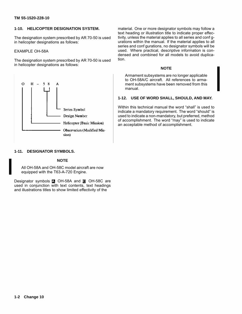
1-10. HELICOPTER DESIGNATION SYSTEM.
The designation system prescribed by AR 70-50 is usedin helicopter designations as follows:
EXAMPLE OH-58A
The designation system prescribed by AR 70-50 is usedin helicopter designations as follows:
1-11. DESIGNATOR SYMBOLS.
NOTE
All OH-58A and OH-58C model aircraft are nowequipped with the T63-A-720 Engine.
Designator symbols A. OH-58A and C. OH-58C areused in conjunction with text contents, text headingsand illustrations titles to show limited effectivity of the
material. One or more designator symbols may follow atext heading or illustration title to indicate proper effec-tivity, unless the material applies to all series and conf g-urations within the manual. If the material applies to allseries and conf gurations, no designator symbols will beused. Where practical, descriptive information is con-densed and combined for all models to avoid duplica-tion.
NOTE
Armament subsystems are no longer applicableto OH-58A/C aircraft. All references to arma-ment subsystems have been removed from thismanual.
1-12. USE OF WORD SHALL, SHOULD, AND MAY.
Within this technical manual the word “shall” is used toindicate a mandatory requirement. The word “should” isused to indicate a non-mandatory, but preferred, methodof accomplishment. The word “may” is used to indicatean acceptable method of accomplishment.
1-2 Change 10

TM 55-1520-228-10
CHAPTER 2HELICOPTER AND SYSTEMS DESCRIPTION
AND OPERATIONS
SECTION I HELICOPTER
2-1. GENERAL.
The OH-58A/C helicopter (f gure 2-1 A. and f gure 2-2C.) is a single engine, observation type helicopter de-signed for landing and takeoff from prepared or unpre-pared surfaces. The fuselage consists of the forwardsection, intermediate or transition section, and the aftor tailboom section. The forward section provides thecabin and fuel cell enclosure as well as pylon support.Entrance to the cabin is provided by two doors on eachside. The pilot station (f gure 2-3 A. and f gure 2-4 C.)is located on the right and the copilot/observer station islocated on the left side of the helicopter. The area aft ofthe pilot and copilot may be used as a cargo/passen-ger compartment. The intermediate section supportsthe engine and includes the equipment and electroniccompartment. The tailboom supports the horizontal sta-bilizer, vertical stabilizer, and tail rotor. The basic struc-ture of the forward section consists of a lower-curvedhoneycomb sandwich panel and an upper longitudinalaluminum beam. The core of the sandwich structure isaluminum alloy throughout. The faces are aluminum al-loy except in the fuel cell region, where they are f ber-glass. The aluminum alloy sandwich panel is capable ofwithstanding the specif ed design cargo loadings, whilethe f berglass sandwich supports the fuel cell pressures.The rotor, transmission, and engine are supported bythe upper longitudinal beam. The upper and lower struc-tures are interconnected by three fuselage bulkheadsand a centerpost to form an integrated structure. Themost forward and aft bulkheads act as carry-throughstructure for the skid landing gear crosstubes. The tail-boom is a monocoque structure with aluminum skin andaluminum substructure.
a. Dimensions. Principal dimensions of the heli-copter areas are shown in f gure 2-5.
b. Turning Radius and Ground Clearance. (Referto f gure 2-6.)
c. Weights. The helicopter weight empty and grossoperating weight will change according to the conf gu-ration or equipment installed for the type of mission tobe performed. Refer to Chapter 6, Weight/Balance andLoading.
d. Crew Con guration. The crew consists of thepilot alone, pilot and copilot, or pilot and observer.
2-2. PASSIVE DEFENSE.
The armor protection is a combination of ceramic andf berglass composite with a small amount of dual hard-ness steel. The armor protection is removable.
Crew Protection.Armor protection is furnished forthe pilot and copilot and consists of panels on seat bot-tom, seat back, and outboard side of each seat.
2-3. LANDING GEAR SYSTEM.
a. Standard System. The landing gear system isa skid type, consisting of two laterally mounted archedcrosstubes, attached to two formed longitudinal skidtubes. Then landing gear structure members are madefrom formed aluminum alloy tubing with steel skid shoesto minimize skid wear. The gear assembly is attachedwith straps/clamps at four points to the fuselage struc-ture, therefore, gear removal for maintenance can easilybe accomplished. The manually retractable and quicklyremovable wheel assemblies have been provided tofacilitate helicopter ground handling operations.
b. High Skid Gear. The high skid gear, when in-stalled, will provide an approximate additional 14 inchesof ground clearance. This will improve landings to beaccomplished in snow and rough terrain areas.
Change 14 2-1
TM 55-1520-228-10
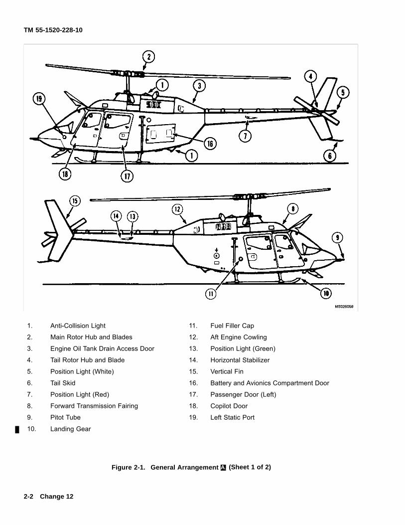
1. Anti-Collision Light 11. Fuel Filler Cap
2. Main Rotor Hub and Blades 12. Aft Engine Cowling
3. Engine Oil Tank Drain Access Door 13. Position Light (Green)
4. Tail Rotor Hub and Blade 14. Horizontal Stabilizer
5. Position Light (White) 15. Vertical Fin
6. Tail Skid 16. Battery and Avionics Compartment Door
7. Position Light (Red) 17. Passenger Door (Left)
8. Forward Transmission Fairing 18. Copilot Door
9. Pitot Tube 19. Left Static Port
10. Landing Gear
Figure 2-1. General Arrangement A. (Sheet 1 of 2)
2-2 Change 12
TM 55-1520-228-10
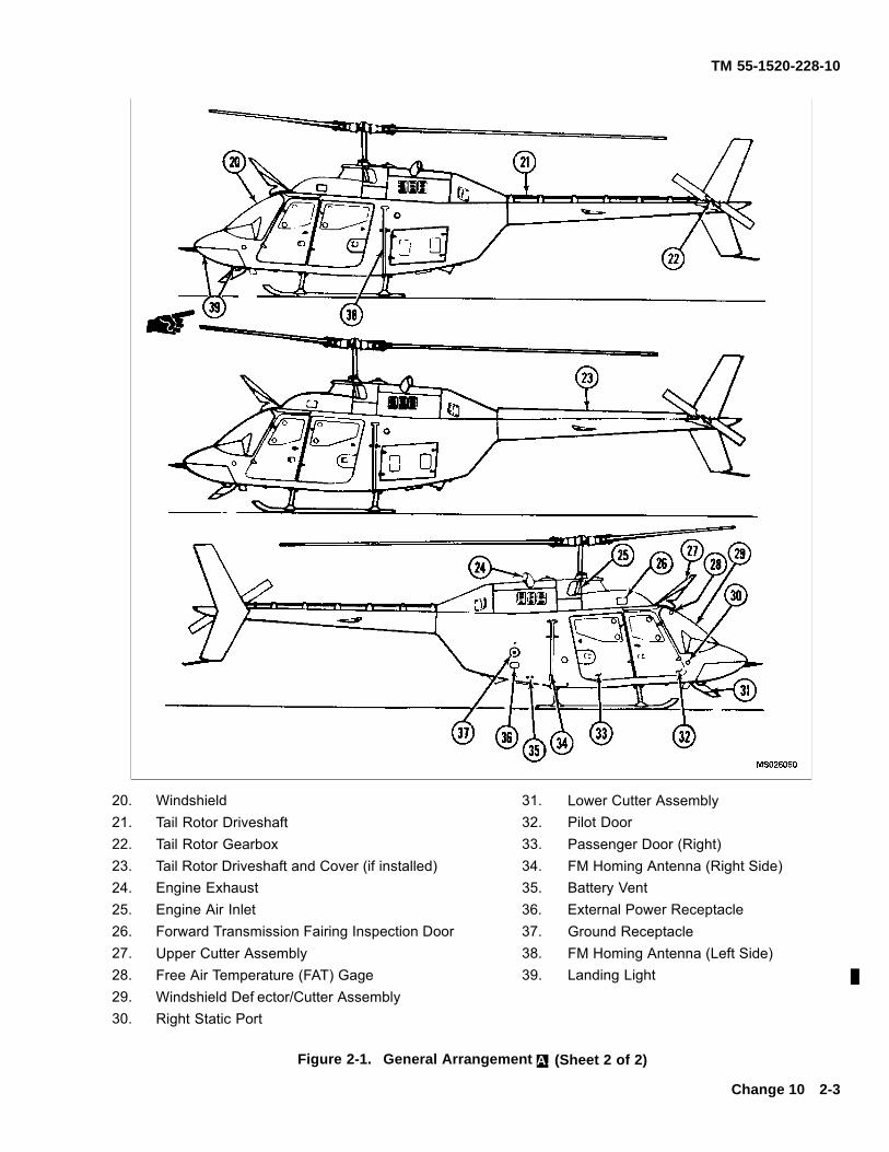
20. Windshield 31. Lower Cutter Assembly21. Tail Rotor Driveshaft 32. Pilot Door22. Tail Rotor Gearbox 33. Passenger Door (Right)23. Tail Rotor Driveshaft and Cover (if installed) 34. FM Homing Antenna (Right Side)24. Engine Exhaust 35. Battery Vent25. Engine Air Inlet 36. External Power Receptacle26. Forward Transmission Fairing Inspection Door 37. Ground Receptacle27. Upper Cutter Assembly 38. FM Homing Antenna (Left Side)28. Free Air Temperature (FAT) Gage 39. Landing Light29. Windshield Def ector/Cutter Assembly30. Right Static Port
Figure 2-1. General Arrangement A. (Sheet 2 of 2)
Change 10 2-3
TM 55-1520-228-10
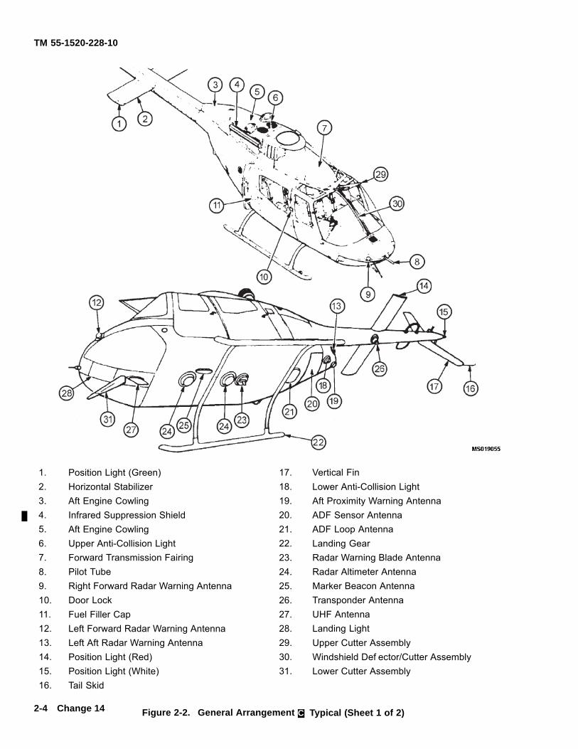
1. Position Light (Green) 17. Vertical Fin2. Horizontal Stabilizer 18. Lower Anti-Collision Light3. Aft Engine Cowling 19. Aft Proximity Warning Antenna4. Infrared Suppression Shield 20. ADF Sensor Antenna5. Aft Engine Cowling 21. ADF Loop Antenna6. Upper Anti-Collision Light 22. Landing Gear7. Forward Transmission Fairing 23. Radar Warning Blade Antenna8. Pilot Tube 24. Radar Altimeter Antenna9. Right Forward Radar Warning Antenna 25. Marker Beacon Antenna10. Door Lock 26. Transponder Antenna11. Fuel Filler Cap 27. UHF Antenna12. Left Forward Radar Warning Antenna 28. Landing Light13. Left Aft Radar Warning Antenna 29. Upper Cutter Assembly14. Position Light (Red) 30. Windshield Def ector/Cutter Assembly15. Position Light (White) 31. Lower Cutter Assembly16. Tail Skid
Figure 2-2. General Arrangement C. Typical (Sheet 1 of 2)2-4 Change 14
TM 55-1520-228-10
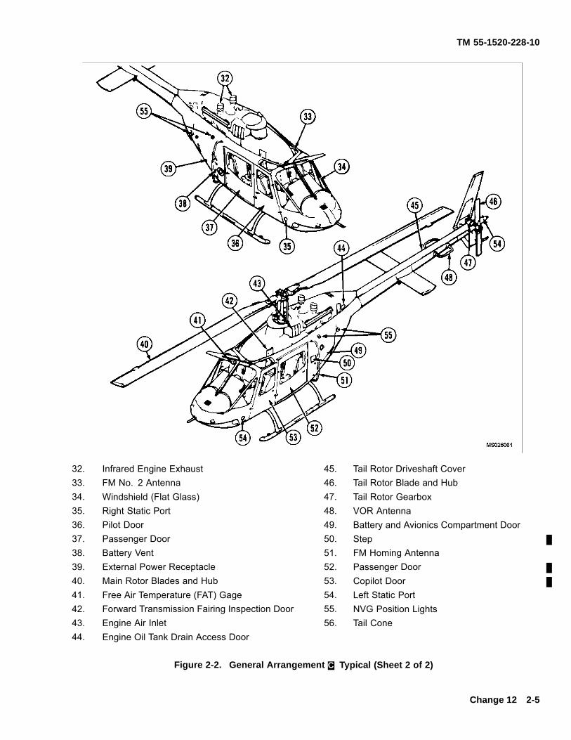
32. Infrared Engine Exhaust 45. Tail Rotor Driveshaft Cover33. FM No. 2 Antenna 46. Tail Rotor Blade and Hub34. Windshield (Flat Glass) 47. Tail Rotor Gearbox35. Right Static Port 48. VOR Antenna36. Pilot Door 49. Battery and Avionics Compartment Door37. Passenger Door 50. Step38. Battery Vent 51. FM Homing Antenna39. External Power Receptacle 52. Passenger Door40. Main Rotor Blades and Hub 53. Copilot Door41. Free Air Temperature (FAT) Gage 54. Left Static Port42. Forward Transmission Fairing Inspection Door 55. NVG Position Lights43. Engine Air Inlet 56. Tail Cone44. Engine Oil Tank Drain Access Door
Figure 2-2. General Arrangement C. Typical (Sheet 2 of 2)
Change 12 2-5
TM 55-1520-228-10
1. Copilot Door Emergency Jettison Handle 9. Pilot Cyclic Stick
2. Overhead Console 10. Pilot Seat
3. Fuel Shutoff Valve 11. Inertia Reel Control Handle
4. Free Air Temperature (FAT) Gage 12. Pilot Collective Stick
5. Pilot Door Emergency Jettison Handle 13. Collective Friction Control Adjustment
6. Instrument Panel 14. Pedestal
7. Magnetic Compass 15. Copilot Seat
8. Anti-Torque Pedals 16. Ignition Key Lock Switch
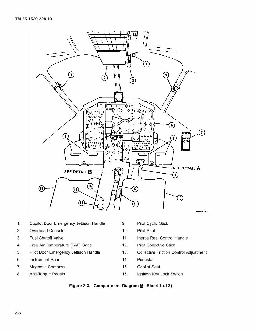
Figure 2-3. Compartment Diagram A. (Sheet 1 of 2)
2-6
TM 55-1520-228-10
17. Governor RPM Switch 25. Radio Transmit Switch
18. Search/Landing Lights 26. Not Used
19. Starter Switch 27. Not Used
20. Engine Idle Release Control 28. Not Used
21. Inertia Reel 29. Not Used
22. Inertia Reel Control Handle 30. Force Trim Switch
23. Not Used 31. Throttle
24. ICS Switch 32. Controllable Landing Light Switch
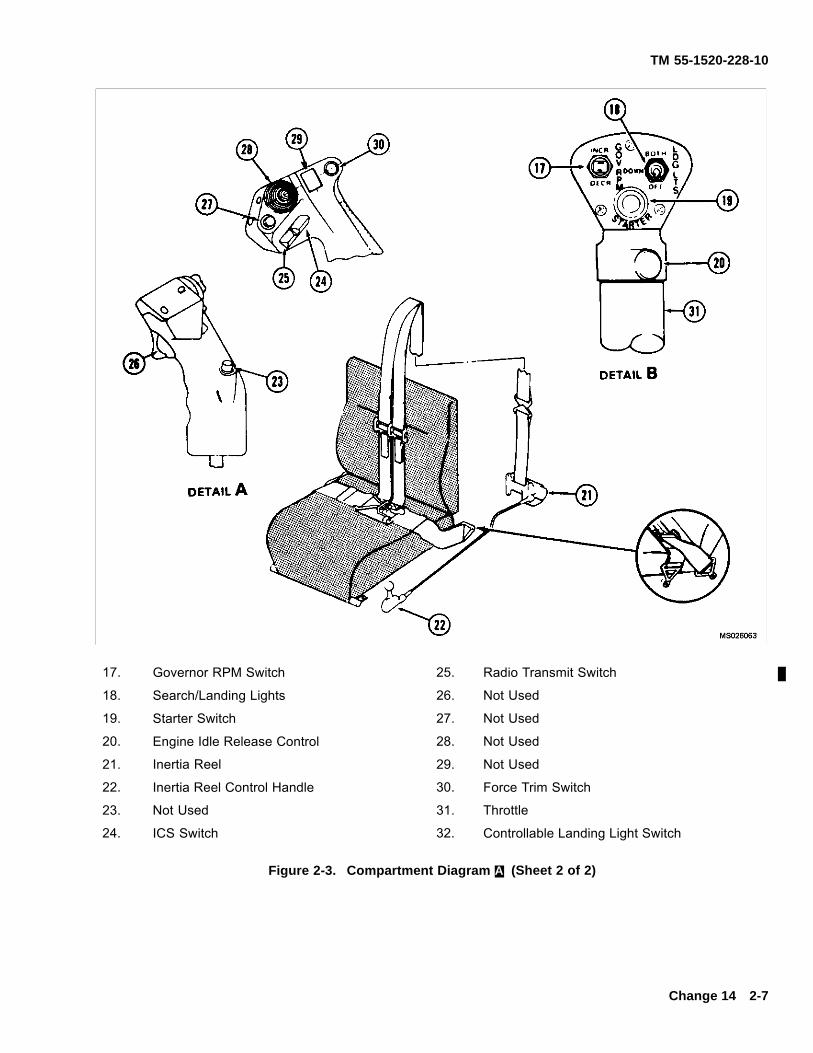
Figure 2-3. Compartment Diagram A. (Sheet 2 of 2)
Change 14 2-7
TM 55-1520-228-10
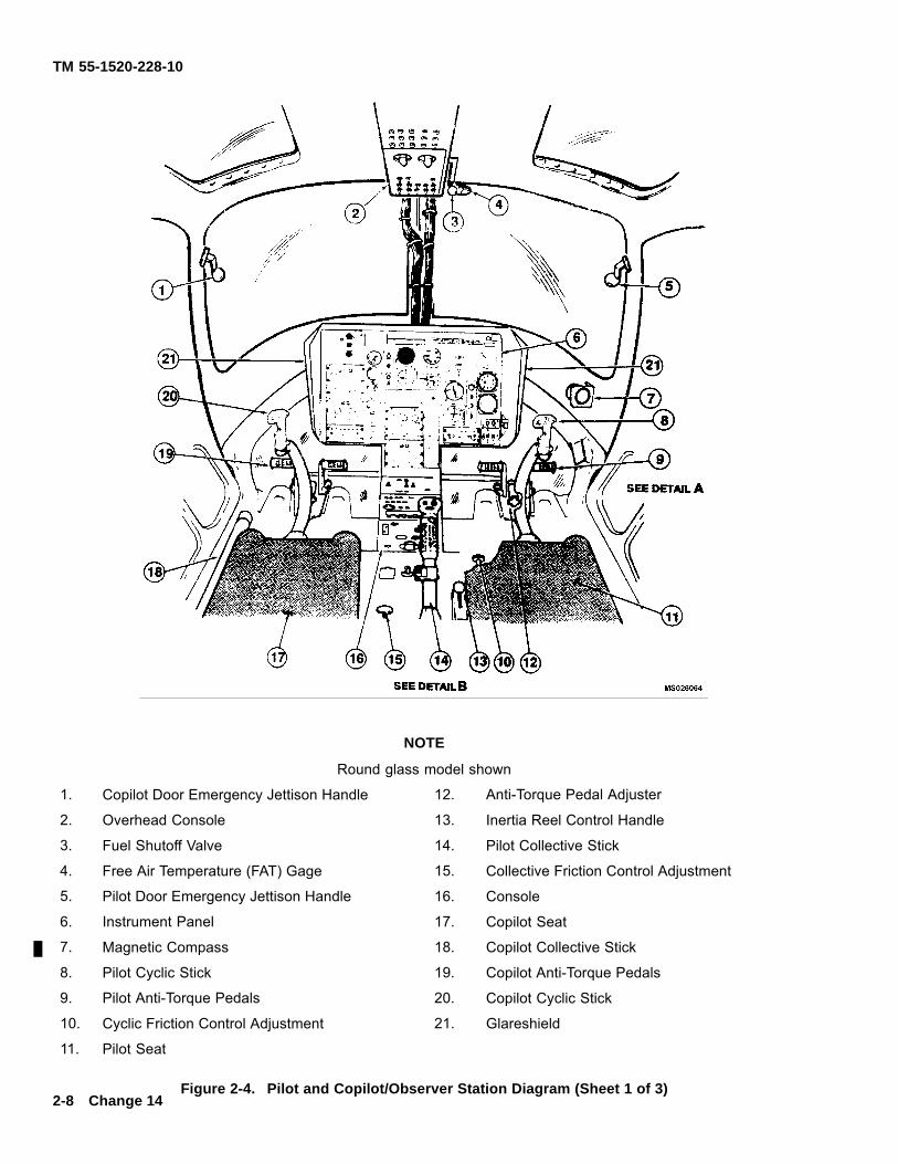
NOTE
Round glass model shown
1. Copilot Door Emergency Jettison Handle 12. Anti-Torque Pedal Adjuster
2. Overhead Console 13. Inertia Reel Control Handle
3. Fuel Shutoff Valve 14. Pilot Collective Stick
4. Free Air Temperature (FAT) Gage 15. Collective Friction Control Adjustment
5. Pilot Door Emergency Jettison Handle 16. Console
6. Instrument Panel 17. Copilot Seat
7. Magnetic Compass 18. Copilot Collective Stick
8. Pilot Cyclic Stick 19. Copilot Anti-Torque Pedals
9. Pilot Anti-Torque Pedals 20. Copilot Cyclic Stick
10. Cyclic Friction Control Adjustment 21. Glareshield
11. Pilot Seat
Figure 2-4. Pilot and Copilot/Observer Station Diagram (Sheet 1 of 3)2-8 Change 14
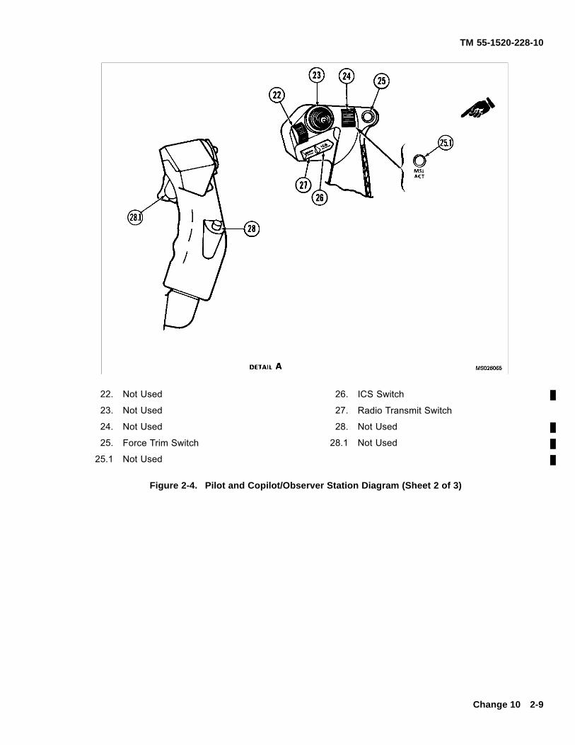
TM 55-1520-228-10
22. Not Used 26. ICS Switch
23. Not Used 27. Radio Transmit Switch
24. Not Used 28. Not Used
25. Force Trim Switch 28.1 Not Used
25.1 Not Used
Figure 2-4. Pilot and Copilot/Observer Station Diagram (Sheet 2 of 3)
Change 10 2-9
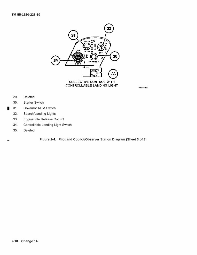
TM 55-1520-228-10
29. Deleted
30. Starter Switch
31. Governor RPM Switch
32. Search/Landing Lights
33. Engine Idle Release Control
34. Controllable Landing Light Switch
35. Deleted
Figure 2-4. Pilot and Copilot/Observer Station Diagram (Sheet 3 of 3)
2-10 Change 14
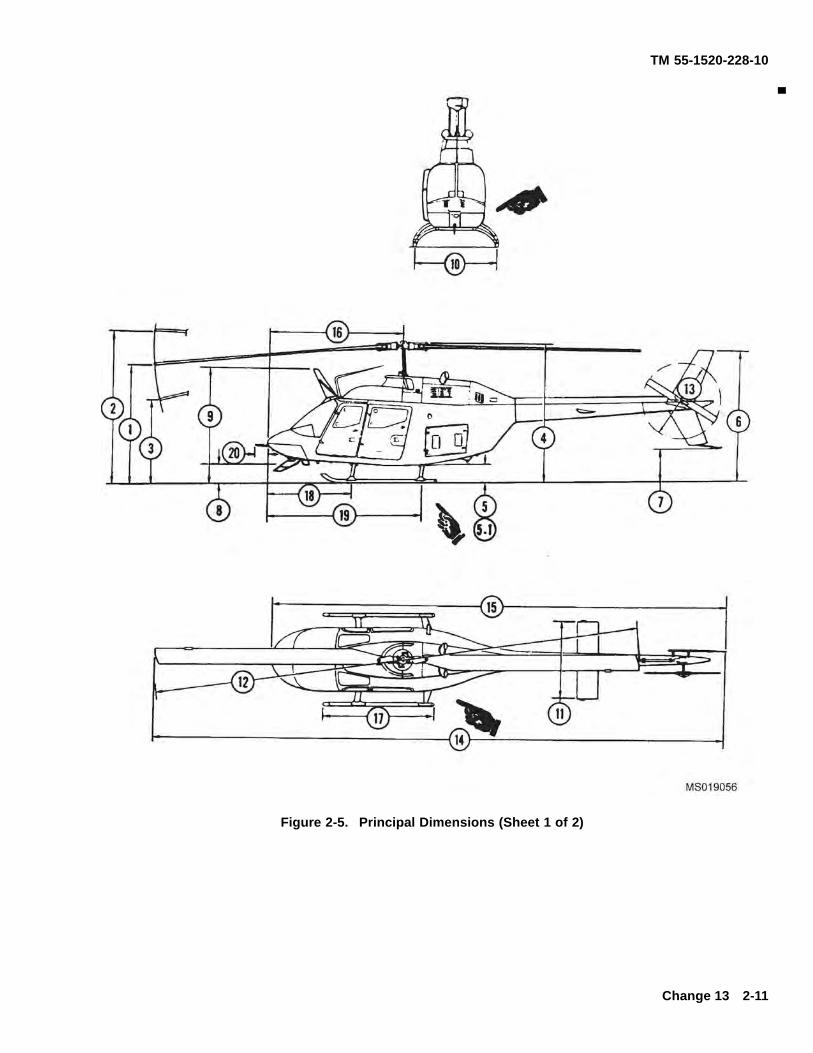
TM 55-1520-228-10
Figure 2-5. Principal Dimensions (Sheet 1 of 2)
Change 13 2-11
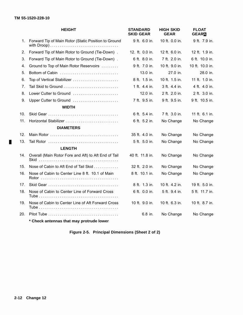
TM 55-1520-228-10
HEIGHT STANDARDSKID GEAR
HIGH SKIDGEAR
FLOATGEARA.
1. Forward Tip of Main Rotor (Static Position to Groundwith Droop) . . . . . . . . . . . . . . . . . . . . . . . . . . . . . . . . . . . .
9 ft. 6.0 in. 10 ft. 0.0 in. 9 ft. 7.9 in.
2. Forward Tip of Main Rotor to Ground (Tie-Down) . 12. ft. 0.0 in. 12 ft. 6.0 in. 12 ft. 1.9 in.
3. Forward Tip of Main Rotor to Ground (Tie-Down) . 6 ft. 8.0 in. 7 ft. 2.0 in. 6 ft. 10.0 in.
4. Ground to Top of Main Rotor Reservoirs . . . . . . . . . 9 ft. 7.0 in. 10 ft. 9.0 in. 10 ft. 10.0 in.
5. Bottom of Cabin . . . . . . . . . . . . . . . . . . . . . . . . . . . . . . . 13.0 in. 27.0 in. 28.0 in.
6. Top of Vertical Stabilizer . . . . . . . . . . . . . . . . . . . . . . . . 8 ft. 1.5 in. 10 ft. 1.5 in. 11 ft. 1.0 in.
7. Tail Skid to Ground . . . . . . . . . . . . . . . . . . . . . . . . . . . . . 1 ft. 4.4 in. 3 ft. 4.4 in. 4 ft. 4.0 in.
8. Lower Cutter to Ground . . . . . . . . . . . . . . . . . . . . . . . . 12.0 in. 2 ft. 2.0 in. 2 ft. 3.0 in.
9. Upper Cutter to Ground . . . . . . . . . . . . . . . . . . . . . . . . 7 ft. 9.5 in. 9 ft. 9.5 in. 9 ft. 10.5 in.
WIDTH
10. Skid Gear . . . . . . . . . . . . . . . . . . . . . . . . . . . . . . . . . . . . . 6 ft. 5.4 in. 7 ft. 3.0 in. 11 ft. 6.1 in.
11. Horizontal Stabilizer . . . . . . . . . . . . . . . . . . . . . . . . . . . . 6 ft. 5.2 in. No Change No Change
DIAMETERS
12. Main Rotor . . . . . . . . . . . . . . . . . . . . . . . . . . . . . . . . . . . . 35 ft. 4.0 in. No Change No Change
13. Tail Rotor . . . . . . . . . . . . . . . . . . . . . . . . . . . . . . . . . . . . . 5 ft. 5.0 in. No Change No Change
LENGTH
14. Overall (Main Rotor Fore and Aft) to Aft End of TailSkid . . . . . . . . . . . . . . . . . . . . . . . . . . . . . . . . . . . . . . . . . .
40 ft. 11.8 in. No Change No Change
15. Nose of Cabin to Aft End of Tail Skid . . . . . . . . . . . . . 32 ft. 2.0 in. No Change No Change
16. Nose of Cabin to Center Line 8 ft. 10.1 of MainRotor . . . . . . . . . . . . . . . . . . . . . . . . . . . . . . . . . . . . . . . . .
8 ft. 10.1 in. No Change No Change
17. Skid Gear . . . . . . . . . . . . . . . . . . . . . . . . . . . . . . . . . . . . . 8 ft. 1.3 in. 10 ft. 4.2 in. 19 ft. 5.0 in.
18. Nose of Cabin to Center Line of Forward CrossTube . . . . . . . . . . . . . . . . . . . . . . . . . . . . . . . . . . . . . . . . . .
6 ft. 0.0 in. 5 ft. 9.4 in. 5 ft. 11.7 in.
19. Nose of Cabin to Center Line of Aft Forward CrossTube . . . . . . . . . . . . . . . . . . . . . . . . . . . . . . . . . . . . . . . . . .
10 ft. 9.0 in. 10 ft. 6.3 in. 10 ft. 8.7 in.
20. Pitot Tube . . . . . . . . . . . . . . . . . . . . . . . . . . . . . . . . . . . . . 6.8 in. No Change No Change
* Check antennas that may protrude lower
Figure 2-5. Principal Dimensions (Sheet 2 of 2)
2-12 Change 12
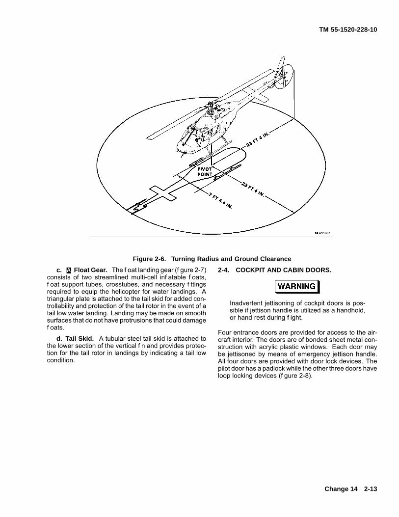
TM 55-1520-228-10
Figure 2-6. Turning Radius and Ground Clearancec. A. Float Gear. The f oat landing gear (f gure 2-7)
consists of two streamlined multi-cell inf atable f oats,f oat support tubes, crosstubes, and necessary f ttingsrequired to equip the helicopter for water landings. Atriangular plate is attached to the tail skid for added con-trollability and protection of the tail rotor in the event of atail low water landing. Landing may be made on smoothsurfaces that do not have protrusions that could damagef oats.
d. Tail Skid. A tubular steel tail skid is attached tothe lower section of the vertical f n and provides protec-tion for the tail rotor in landings by indicating a tail lowcondition.
2-4. COCKPIT AND CABIN DOORS.
Inadvertent jettisoning of cockpit doors is pos-sible if jettison handle is utilized as a handhold,or hand rest during f ight.
Four entrance doors are provided for access to the air-craft interior. The doors are of bonded sheet metal con-struction with acrylic plastic windows. Each door maybe jettisoned by means of emergency jettison handle.All four doors are provided with door lock devices. Thepilot door has a padlock while the other three doors haveloop locking devices (f gure 2-8).
Change 14 2-13
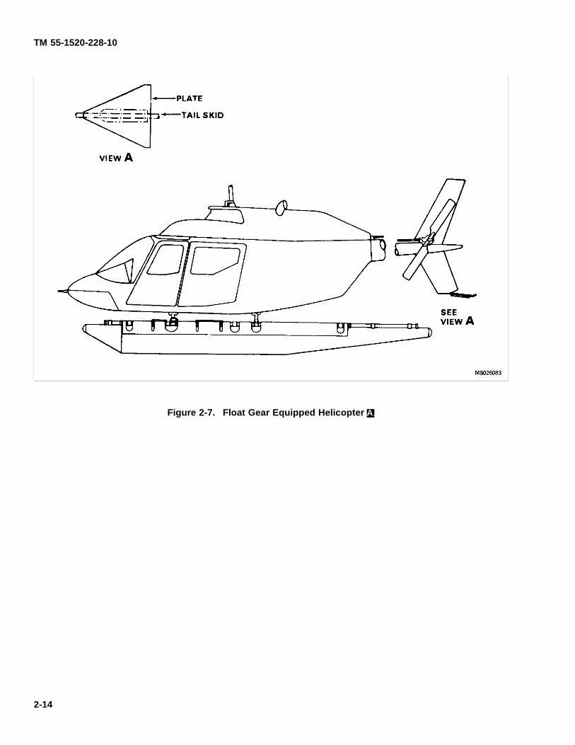
TM 55-1520-228-10
Figure 2-7. Float Gear Equipped Helicopter A.
2-14
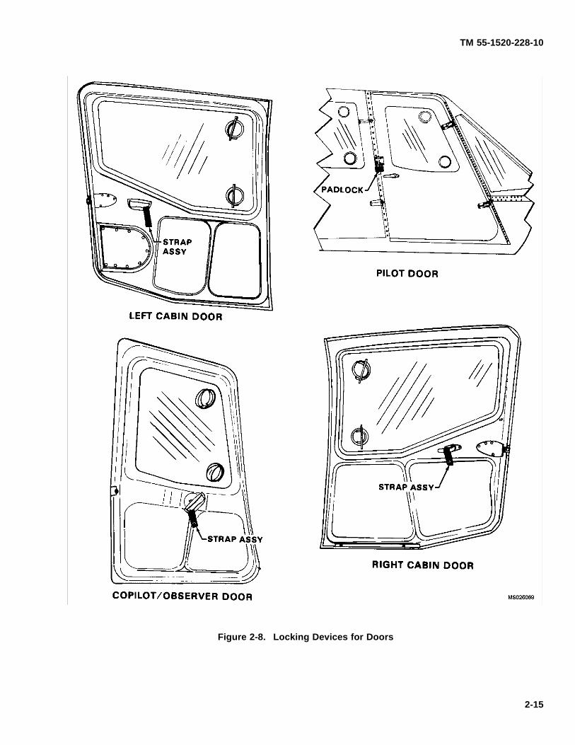
TM 55-1520-228-10
Figure 2-8. Locking Devices for Doors
2-15
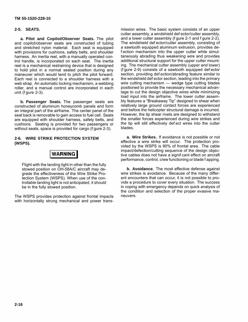
TM 55-1520-228-10
2-5. SEATS.
a. Pilot and Copilot/Observer Seats. The pilotand copilot/observer seats are constructed of tubingand stretched nylon material. Each seat is equippedwith provisions for cushions, safety belts, and shoulderharness. An inertia reel, with a manually operated con-trol handle, is incorporated on each seat. The inertiareel is a mechanical restraining device that is designedto hold pilot in a normal seated position during anymaneuver which would tend to pitch the pilot forward.Each reel is connected to a shoulder harness with aweb strap. An automatic locking mechanism, a webbingroller, and a manual control are incorporated in eachunit (f gure 2-3).
b. Passenger Seats. The passenger seats areconstructed of aluminum honeycomb panels and forman integral part of the airframe. The center panel of theseat back is removable to gain access to fuel cell. Seatsare equipped with shoulder harness, safety belts, andcushions. Seating is provided for two passengers orwithout seats, space is provided for cargo (f gure 2-3).
2-6. WIRE STRIKE PROTECTION SYSTEM(WSPS).
Flight with the landing light in other than the fullystowed position on OH-58A/C aircraft may de-grade the effectiveness of the Wire Strike Pro-tection System (WSPS). When use of the con-trollable landing light is not anticipated, it shouldbe in the fully stowed position.
The WSPS provides protection against frontal impactswith horizontally strung mechanical and power trans-
mission wires. The basic system consists of an uppercutter assembly, a windshield def ector/cutter assembly,and a lower cutter assembly (f gure 2-1 and f gure 2-2).The windshield def ector/cutter assembly, consisting ofa sawtooth equipped aluminum extrusion, provides de-f ection mechanism into the upper cutter while simul-taneously abrading thus weakening wire and providesadditional structural support for the upper cutter mount-ing. The mechanical cutter assembly (upper and lower)(f gure 2-9) consists of a sawtooth equipped def ectorsection, providing def ection/abrading feature similar tothe windshield def ector section, leading into the primarywire cutting mechanism — wedge type cutting bladespositioned to provide the necessary mechanical advan-tage to cut the design objective wires while minimizingload input into the airframe. The lower cutter assem-bly features a “Breakaway Tip” designed to shear whenrelatively large ground contact forces are experiencedand before the helicopter structural damage is incurred.However, the tip shear rivets are designed to withstandthe smaller forces experienced during wire strikes andthe tip will still effectively def ect wires into the cutterblades.
a. Wire Strikes. If avoidance is not possible or noteffective a wire strike will occur. The protection pro-vided by the WSPS is 90% of frontal area. The cableimpact/defection/cutting sequence of the design objec-tive cables does not have a signif cant effect on aircraftperformance, control, crew functioning or blade f apping.
b. Avoidance. The most effective defense againstwire strikes is avoidance. Because of the many differ-ent encounters that can occur, it is not possible to pro-vide a procedure to cover every situation. The successin coping with emergency depends on quick analysis ofthe condition and selection of the proper evasive ma-neuvers.
2-16
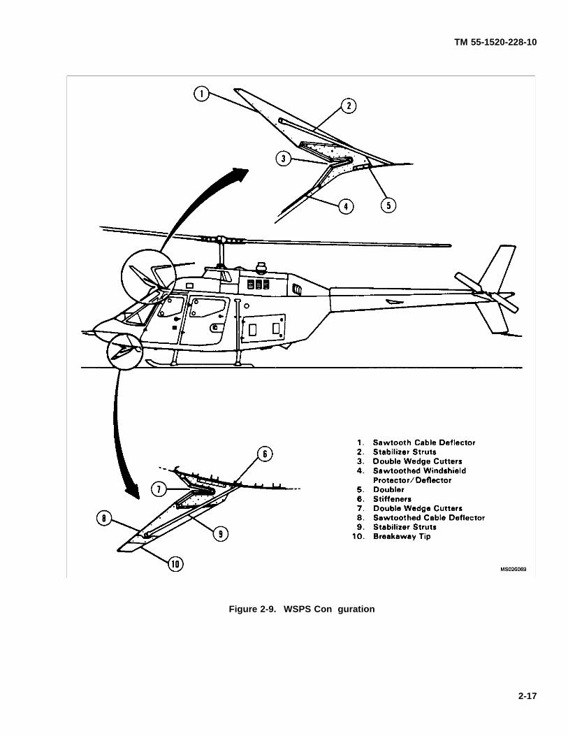
TM 55-1520-228-10
Figure 2-9. WSPS Con guration
2-17
TM 55-1520-228-10
SECTION II EMERGENCY EQUIPMENT
2-7. FIRST AID KIT.
An aeronautical type f rst aid kit is located on the rightside of the center support column.
2-8. FIRE EXTINGUISHER.
A portable f re extinguisher is mounted in a bracket lo-cated on the right side of the center support column (f g-ure 9-1).
SECTION III ENGINES AND RELATED SYSTEMS
2-9. ENGINE.
The OH-58A/C helicopter is equipped with a T63-A-720turbine engine (f gure 2-11). The engine is designed forlow fuel consumption, light weight, minimum size, max-imum reliability and ease of maintenance. The engineis installed aft of the mast and the passenger compart-ment. The engine cowl aft of the engine air inlet is re-movable as a single unit or the hinged section the lengthof the engine on either side may be opened individually.The aft fairing covers the engine oil cooler, provides tailrotor driveshaft access and provides air intake for theengine oil cooler. The major engine components are asfollows:
a. Compressor. Air enters the engine through theparticle separator to the compressor inlet and is com-pressed by six axial compressor stages and one cen-trifugal stage. The particle separator removes dirt andother contaminates from the incoming air and ejects thedirt out ducts on either side of the fairing. This allowscleaned air to enter the engine compressor section. Thecompressed air is discharged through the scroll type dif-fuser into two external ducts which convey the air to thecombustion section.
b. Combustion Section. The combustion sectionconsists of the outer combustion case and the combus-tion liner. A spark igniter and a fuel nozzle are mountedin the aft end of the outer combustion case. Air en-ters the single combustion liner at the aft end, throughholes in the liner dome and skin. The air is mixed withfuel sprayed from the fuel nozzle and combustion takes
place. Combustion gasses move forward out of thecombustion liner to the f rst-stage gas producer turbinenozzle.
c. Turbine. The turbine consists of a gas producerturbine support, a power turbine support, a turbine andexhaust collector support, a gas producer turbine rotor,and a power turbine rotor. The turbine is mounted be-tween the combustion section and the power and ac-cessory gearbox. The two-stage gas producer turbinedrives the compressor and accessory gear train. Gasdischarged from the gas producer turbine drives the two-stage power turbine which furnishes the output power ofthe engine. The gas from the power turbine dischargesin an upward direction through twin ducts in the turbineand exhaust collector support.
d. Power and Accessories Gearbox. The mainpower and accessory drive gear train are enclosedin a single gear case. The gear case serves as astructural support of the engine. All engine componentsincluding engine mounted accessories are attachedto the case. A two-stage helical and spur gear set isused to reduce rotational speed from the power turbineto the output drive spline. Accessories driven by thepower turbine gear train (N2) are the power turbine (N2)tachometer-generator, power turbine governor, andtorquemeter. The gas producer (N1) drives the com-pressor, and through an associated gear train drives thefuel pump, gas producer (N1) tachometer-generator,gas producer fuel control, starter-generator, and engineoil pump.
2-18 Change 11

TM 55-1520-228-10
Figure 2-10. HAS BEEN DELETED.
Change 11 2-19
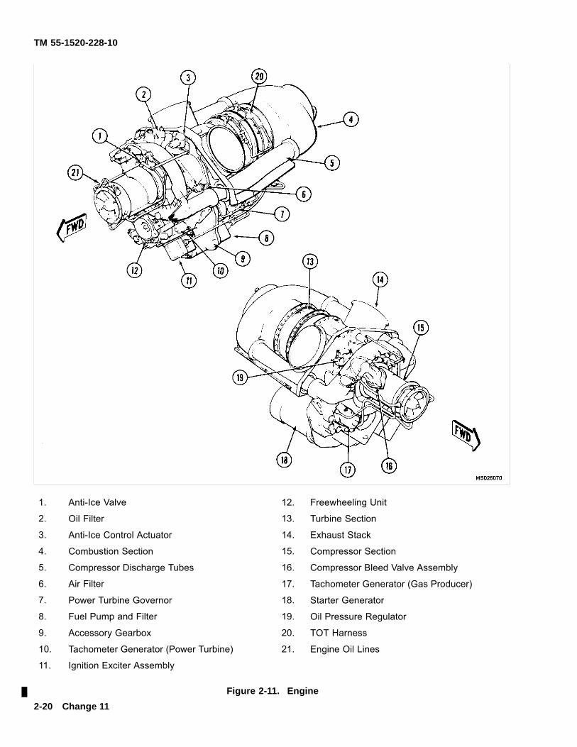
TM 55-1520-228-10
1. Anti-Ice Valve 12. Freewheeling Unit
2. Oil Filter 13. Turbine Section
3. Anti-Ice Control Actuator 14. Exhaust Stack
4. Combustion Section 15. Compressor Section
5. Compressor Discharge Tubes 16. Compressor Bleed Valve Assembly
6. Air Filter 17. Tachometer Generator (Gas Producer)
7. Power Turbine Governor 18. Starter Generator
8. Fuel Pump and Filter 19. Oil Pressure Regulator
9. Accessory Gearbox 20. TOT Harness
10. Tachometer Generator (Power Turbine) 21. Engine Oil Lines
11. Ignition Exciter Assembly
Figure 2-11. Engine2-20 Change 11
TM 55-1520-228-10
2-10. ENGINE COMPARTMENT COOLING.
Openings are provided on both sides of the engine andtop cowling for compartment cooling. The center cowlsection houses the engine air inlet, the inlet bellmouthand the forward f rewall. Suspended below the engine isa stainless f re shield. Below the f re shield is a titaniumf oor which acts as a drip pan and also gives insulationfrom heat.
2-11. INDUCTION SYSTEM.
The engine air inlet system consists of an induction fair-ing with inlets on each outboard side. This fairing pro-vides mounting for the particle separator. The particleseparator removes dirt and other contaminates from theincoming air and ejects the dirt out eductor tubes on ei-ther side of the fairing. This allows cleaned air to en-ter the engine compressor section. Removable reversef ow inlet fairings may be installed over the air inletson modif ed induction fairings. These reverse f ow fair-ings minimize ram effect of falling or blowing snow, thuspermitting effective operation of the particle separatorand preventing engine f ame-out caused by ingestion ofsnow.
a. Intake Ducting. The engine air intake ductingconsists of louvered openings and a large circular airinlet opening. The louvered openings are located onleft and right cowl panels.
b. Particle Separator. Foreign matter is removedfrom the engine inlet air by a centrifugal-type particleseparator. The particle separator consists of a group ofseparator tube assemblies arranged in rows and posi-tioned in a front and rear sheetmetal panel and a scav-enge system. The separator tube assemblies consistof an inlet tube, a swirl tube which is bonded inside theinlet tube, and an outlet tube. The scavenge systemconsists of a bleed air manifold, bleed air nozzles, andejector tubes which are contained in two ejector boxeslocated beneath the separator tube assemblies. Thebleed air manifold is attached to the ejector boxes and isconnected directly to the engine compressor scroll withbleed air inlet f ttings. Air enters the inlet tube and isspun by the swirl tube. Clean air then enters the engineinlet plenum chamber through the outlet tube while for-
eign material is centrifuged into the scavenge system.The foreign material is ejected overboard by the vac-uum-cleaner effect created by engine bleed air as it isdischarged through venturies in the eductor tubes. Re-verse f ow inlet fairings may be attached to the engine airinlets. These sheet metal fairings make it impossible forair to enter the plenum chamber without f rst making two180° turns. These abrupt changes in airf ow greatly re-duce the probability of engine f ame-out associated withsnow ingestion.
2-12. ENGINE INLET ANTI-ICING SYSTEM
The compressor inlet guide vanes and front bearing sup-port hub are the only engine components with anti-icingprovision. Anti-icing is provided by the use of compres-sor bleed air. Anti-icing is actuated by placing ENG DE-ICE switch on overhead console (f gure 2-12) to ENGDEICE position.
2-13. ENGINE FUEL CONTROL SYSTEM.
The system controls engine power output by controllingthe gas producer speed. Gas producer speed levels areestablished by the action of the power turbine fuel gover-nor which senses power turbine speed. The power tur-bine (load) speed is selected by the operator and powerrequired to maintain this speed is automatically main-tained by power turbine governor action on metered fuelf ow. The power turbine governor lever schedules thepower turbine governor requirements. The power tur-bine governor schedules the gas producer speed to achanged power output to maintain output shaft speed.
a. Deleted.
b. Throttle. Rotating the throttle (f gure 2-4) to thefull open position allows the power turbine governor tomaintain a constant rpm. Rotating the throttle towardthe closed position will cause the rpm to be manuallyselected instead of automatically selected by the powerturbine governor. Rotating the throttle past the engine-idle stop to the fully closed position shuts off fuel f ow.A manually operated idle stop is incorporated to preventinadvertent throttle closure. The idle stop is controlledby the engine idle release control (f gure 2-4).
Change 10 2-21
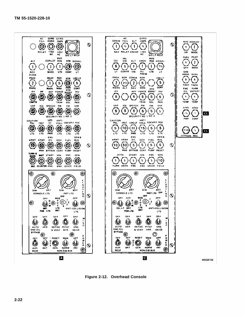
TM 55-1520-228-10
Figure 2-12. Overhead Console
2-22
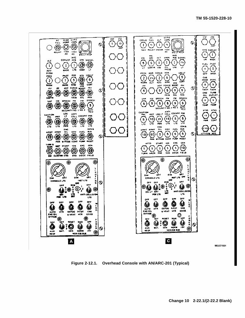
TM 55-1520-228-10
Figure 2-12.1. Overhead Console with AN/ARC-201 (Typical)
Change 10 2-22.1/(2-22.2 Blank)

TM 55-1520-228-10
c. Droop Compensator. A droop compensatormaintains engine rpm (N2) as power demand is in-creased. The compensator is a direct mechanicallinkage between the collective stick and the speedselector lever on the N2 governor. Droop is def nedas the speed change in N2 rpm as power is increasedfrom a no-load condition. Without droop compensation,instability would develop as engine output is increased,resulting in N1 speed overshooting or hunting the valuenecessary to satisfy the new power condition. If N2power is allowed to droop, other than momentarily, thereduction in rotor speed could become critical.
d. Engine Idle Release Control. The engine idlerelease is a spring loaded plunger mounted on theswitch box of the pilot collective stick (f gure 2-3 andf gure 2-4). The plunger prevents the pilot from acciden-tally retarding the throttle beyond engine idle position.This acts as a safety feature by preventing inadvertentengine shutdown. The plunger need not be depressedwhen performing an engine start or runup; however,the plunger must be depressed when accomplishingan engine shutdown or when it is desired to retard thepower control below the engine idle position.
e. Governor RPM Switch. The GOV INCR/DECRswitch is mounted on the pilot collective stick (f gure 2-3and 2-4). The switch is a three-position momentary typeand is held in the INCR position (FWD) to increase thepower turbine (N2) speed or DECR position (AFT) to de-crease the power turbine (N2) speed. Regulated powerturbine speed may be adjusted in f ight through the op-erating range by movement of the switch as required.
f. Gas Producer Fuel Control. The gas producerfuel control has a bypass valve, metering valve, ac-celeration bellows, governing and enrichment bellows,
manually operated cutoff valve, maximum pressurerelief valve, and a torque tube seal and lever assembly.A maximum pressure relief valve is incorporated toprotect the system from excessive fuel pressure.
g. Power Turbine Governor. The power turbinespeed is scheduled by the power turbine governorlever and the power turbine speed scheduling cam.The cam sets a governor spring load which opposesa speed-weight output. Overspeed protection of thepower turbine governor becomes effective at approxi-mately 108% N2. This governing action will result in apulsating increase/decrease of engine power.
h. Deleted.
i. Fuel Pump and Filter Assembly. The fuel pumpand f lter assembly incorporates a single gear-typepumping element, a low pressure barrier f lter, a f lterbypass valve, and a bypass pressure regulating valve.Fuel enters the engine fuel system at the inlet port of thepump and passes through the low pressure f lter beforeentering the gear element. The f lter bypass valveallows fuel to bypass the f lter element if it becomesclogged. The bypass return f ow from the fuel control ispassed back to the inlet of the gear element through apressure regulating valve which maintains the bypassf ow pressure above inlet pressure.
j. Deleted.
k. Fuel Nozzle. The fuel nozzle is a single-entrydual orif ce type unit which contains an integral valvefor dividing primary and secondary f ow.
l. Deleted.
Change 14 2-23
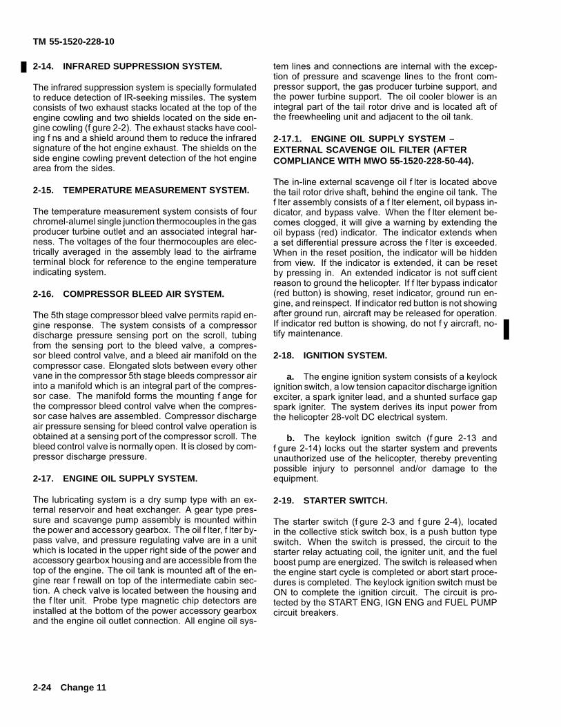
TM 55-1520-228-10
2-14. INFRARED SUPPRESSION SYSTEM.
The infrared suppression system is specially formulatedto reduce detection of IR-seeking missiles. The systemconsists of two exhaust stacks located at the top of theengine cowling and two shields located on the side en-gine cowling (f gure 2-2). The exhaust stacks have cool-ing f ns and a shield around them to reduce the infraredsignature of the hot engine exhaust. The shields on theside engine cowling prevent detection of the hot enginearea from the sides.
2-15. TEMPERATURE MEASUREMENT SYSTEM.
The temperature measurement system consists of fourchromel-alumel single junction thermocouples in the gasproducer turbine outlet and an associated integral har-ness. The voltages of the four thermocouples are elec-trically averaged in the assembly lead to the airframeterminal block for reference to the engine temperatureindicating system.
2-16. COMPRESSOR BLEED AIR SYSTEM.
The 5th stage compressor bleed valve permits rapid en-gine response. The system consists of a compressordischarge pressure sensing port on the scroll, tubingfrom the sensing port to the bleed valve, a compres-sor bleed control valve, and a bleed air manifold on thecompressor case. Elongated slots between every othervane in the compressor 5th stage bleeds compressor airinto a manifold which is an integral part of the compres-sor case. The manifold forms the mounting f ange forthe compressor bleed control valve when the compres-sor case halves are assembled. Compressor dischargeair pressure sensing for bleed control valve operation isobtained at a sensing port of the compressor scroll. Thebleed control valve is normally open. It is closed by com-pressor discharge pressure.
2-17. ENGINE OIL SUPPLY SYSTEM.
The lubricating system is a dry sump type with an ex-ternal reservoir and heat exchanger. A gear type pres-sure and scavenge pump assembly is mounted withinthe power and accessory gearbox. The oil f lter, f lter by-pass valve, and pressure regulating valve are in a unitwhich is located in the upper right side of the power andaccessory gearbox housing and are accessible from thetop of the engine. The oil tank is mounted aft of the en-gine rear f rewall on top of the intermediate cabin sec-tion. A check valve is located between the housing andthe f lter unit. Probe type magnetic chip detectors areinstalled at the bottom of the power accessory gearboxand the engine oil outlet connection. All engine oil sys-
tem lines and connections are internal with the excep-tion of pressure and scavenge lines to the front com-pressor support, the gas producer turbine support, andthe power turbine support. The oil cooler blower is anintegral part of the tail rotor drive and is located aft ofthe freewheeling unit and adjacent to the oil tank.
2-17.1. ENGINE OIL SUPPLY SYSTEM –EXTERNAL SCAVENGE OIL FILTER (AFTERCOMPLIANCE WITH MWO 55-1520-228-50-44).
The in-line external scavenge oil f lter is located abovethe tail rotor drive shaft, behind the engine oil tank. Thef lter assembly consists of a f lter element, oil bypass in-dicator, and bypass valve. When the f lter element be-comes clogged, it will give a warning by extending theoil bypass (red) indicator. The indicator extends whena set differential pressure across the f lter is exceeded.When in the reset position, the indicator will be hiddenfrom view. If the indicator is extended, it can be resetby pressing in. An extended indicator is not suff cientreason to ground the helicopter. If f lter bypass indicator(red button) is showing, reset indicator, ground run en-gine, and reinspect. If indicator red button is not showingafter ground run, aircraft may be released for operation.If indicator red button is showing, do not f y aircraft, no-tify maintenance.
2-18. IGNITION SYSTEM.
a. The engine ignition system consists of a keylockignition switch, a low tension capacitor discharge ignitionexciter, a spark igniter lead, and a shunted surface gapspark igniter. The system derives its input power fromthe helicopter 28-volt DC electrical system.
b. The keylock ignition switch (f gure 2-13 andf gure 2-14) locks out the starter system and preventsunauthorized use of the helicopter, thereby preventingpossible injury to personnel and/or damage to theequipment.
2-19. STARTER SWITCH.
The starter switch (f gure 2-3 and f gure 2-4), locatedin the collective stick switch box, is a push button typeswitch. When the switch is pressed, the circuit to thestarter relay actuating coil, the igniter unit, and the fuelboost pump are energized. The switch is released whenthe engine start cycle is completed or abort start proce-dures is completed. The keylock ignition switch must beON to complete the ignition circuit. The circuit is pro-tected by the START ENG, IGN ENG and FUEL PUMPcircuit breakers.
2-24 Change 11
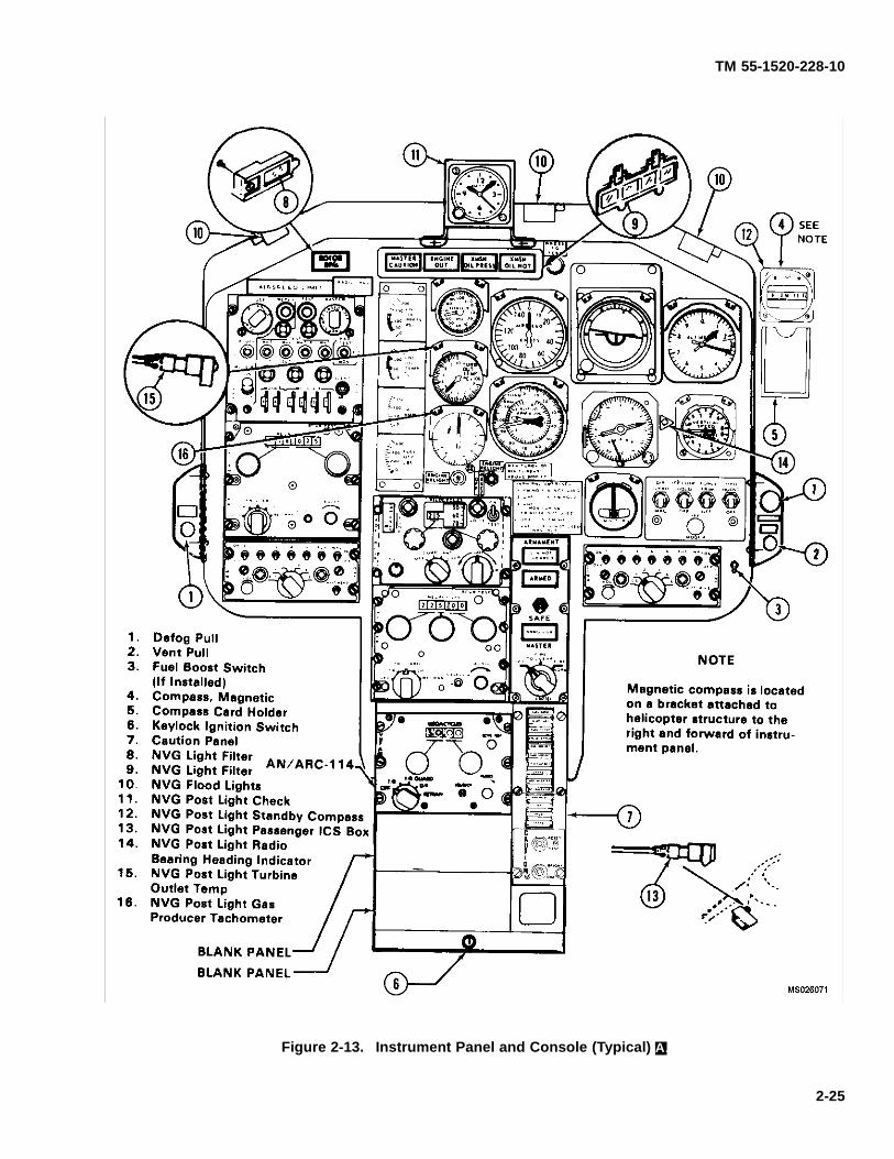
TM 55-1520-228-10
Figure 2-13. Instrument Panel and Console (Typical) A.
2-25
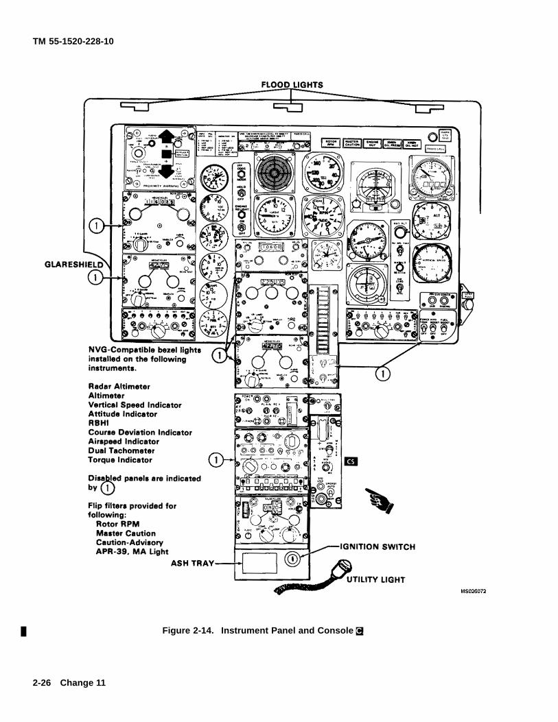
TM 55-1520-228-10
Figure 2-14. Instrument Panel and Console C.
2-26 Change 11
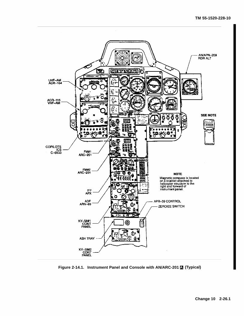
TM 55-1520-228-10
Figure 2-14.1. Instrument Panel and Console with AN/ARC-201 A. (Typical)
Change 10 2-26.1
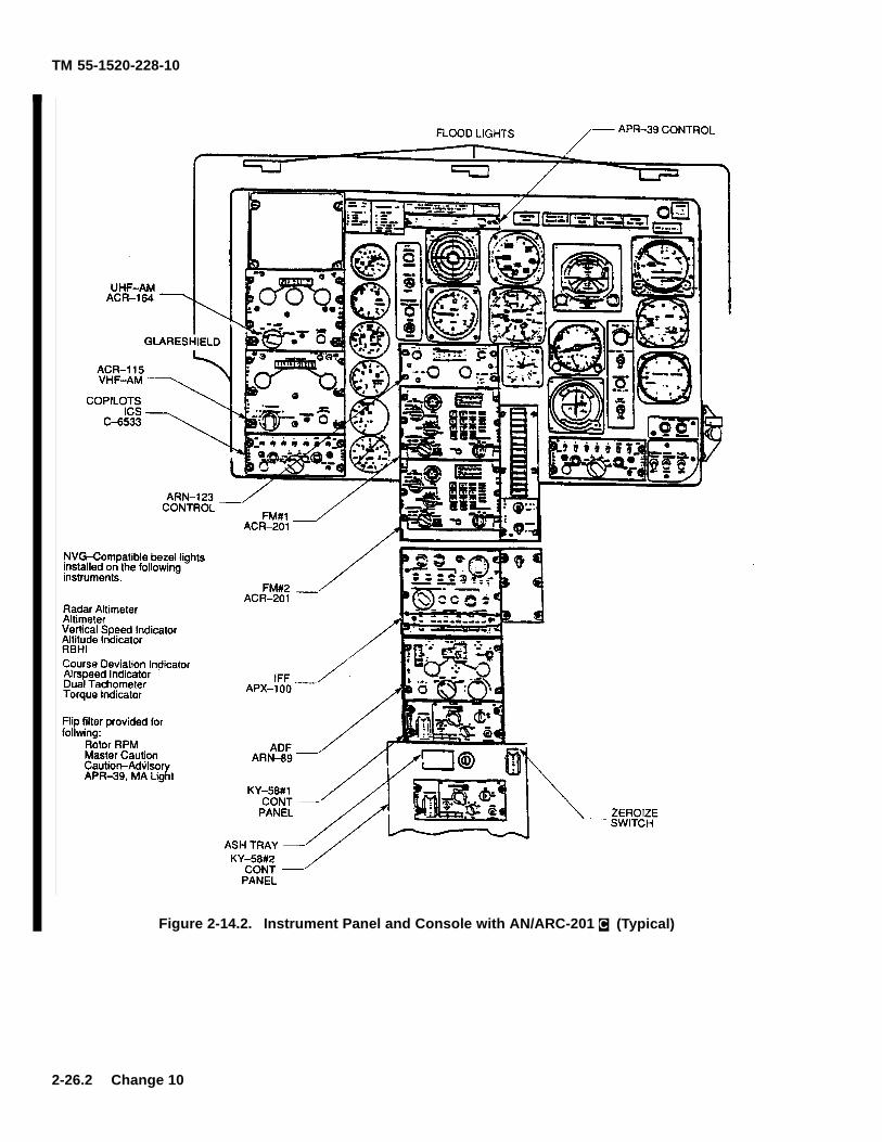
TM 55-1520-228-10
Figure 2-14.2. Instrument Panel and Console with AN/ARC-201 C. (Typical)
2-26.2 Change 10
TM 55-1520-228-10
2-20. ENGINE AUTOMATIC RELIGHT SYSTEM(NOT USED).
An ENGINE RELIGHT ON/OFF switch and an ENGINERELIGHT light may be found on the instrument panel.The automatic relight system has been deactivated andis not functional. There is no approved functional systemfor the OH-58A/C helicopter.
2-21. ENGINE INSTRUMENTS AND INDICATORS.
The engine instruments and indicators are mounted inthe instrument panel or the caution panel in the lowerconsole. They are described in the following paragraphsand shown in f gure 2-13 and f gure 2-14.
a. Engine Out Warning. An RPM sensor is con-nected to the gas producer tachometer. Power is sup-plied from the CAUTION PNL LTS circuit breaker andconnections are made to the ENGINE OUT warning light(f gure 2-13 and f gure 2-14), and to a tone generatorwhich produces a tone in the pilot headset. The warn-ing system is activated when N1 is below 55 ± 3% andis deactivated above that N1 speed. The audio signal isthe same as the low rotor audio signal.
b. Engine Out Audio Warning. A switch con-nected to the collective lever disables the engine outaudio warning when the collective lever is in the fulldown position.
c. Torquemeter. The torquemeter (f gure 2-13and f gure 2-14), located in the instrument panel, dis-plays percent of torque produced by the engine. Thetorquemeter is a direct reading, wetline indicator.
d. A. Turbine Outlet Temperature Gage. A ther-mocouple harness assembly with four integral probesis used to sense the temperature of the gases on theoutlet side of the gas producer turbine rotor. A DC volt-age which is directly proportional to the gas tempera-ture it senses, is generated by each thermocouple. Thethermocouple and thermocouple harness provide an av-erage of the four voltages representative of the turbineoutlet temperature (TOT) and this is the temperature in-dication on the TOT gage on the instrument panel.
e. C. Turbine Outlet Temperature Indicator. Theturbine outlet temperature (TOT) indicator (f gure 2-14),located in the instrument panel, displays temperature indegrees Celsius of the exhaust gases in the N1 turbineoutlet area. The indicator is powered by 28 Vdc andprotected by TURB OUTLET TEMP circuit breaker.
f. Gas Producer Tachometer. The gas producertachometer generator, located on the engine, generatesan AC voltage with a frequency that is a function ofgas producer turbine rotor N1 RPM. The output of thetachometer generator is delivered to the gas producertachometer indicator which indicates the frequency interms of percent RPM of gas producer turbine speed.The power for the gas producer tachometer is enginegenerated A. . The helicopter electrical system powersthe C. model and is protected by a gas producer tachcircuit breaker.
g. Dual Tachometer. The dual tachometer (f gure2-13 A. and f gure 2-14 C.) located in the instrumentpanel displays percent RPM of the engine and rotor.The outer scale is marked Engine and the inner scale ismarked Rotor. The OH-58A indicators are direct read-ing instruments which are not dependent of the electricalsystem. The OH-58C tach indicators are 28v DC-pow-ered and protected by the DUAL TACH and GAS PRODTACH circuit breakers.
h. A. Oil Pressure Gage. The oil pressure indica-tor, located on the instrument panel, is a direct-reading,wet-line system. Pressure from the pressure side of theoil pump is indicted in psi. Refer to f gure 2-13.
i. A.Oil Temperature Gage. The engine oil tem-perature gage, located on the instrument panel, is con-nected to an electrical resistance type thermocouple andindicates the temperature of the oil at the oil tank outlet.
j. C. Oil Pressure/Temperature Indicator. The en-gine oil pressure/temperature indicator (f gure 2-14), lo-cated in the instrument panel, displays engine oil pres-sure in psi and temperature in degrees Celsius. Thetemperature circuit is powered by 28 Vdc and protectedby ENG OIL TEMP circuit breaker. The oil pressure por-tion of the indicator is a direct reading wetline system.
Change 10 2-27
TM 55-1520-228-10
Illumination of the engine oil bypass light mayindicate a severe leak is present or developing,which could result in total loss of engine oil in ashort period of time.
k. Engine Oil Bypass Caution Light. The ENGOIL BYPASS caution light (f gure 2-13 and f gure 2-14),located on the caution panel, will illuminate when the oiltank level is approximately 3 pints low. With the ENGOIL BYPASS switch (f gure 2-12) in the AUTO positionthe engine oil will bypass the oil cooler. A signif cant risein engine oil temperature will occur and engine failurecan occur in a few minutes due to excessive engineoil temperature and/or engine oil loss. The switch inAUTO position is designed for combat operations only
(due to the potential for damage to the oil cooler byhostile f re) to provide the pilot a little additional time tof y out of the immediate enemy danger area only. Theswitch should be in the OFF position for operation innoncombat environment. The circuit is powered by 28Vdc and is protected by the CAUTION PNL LTS circuitbreaker.
l. Engine Chip Detector. There are two electricalengine chip detectors located in the accessory gearcase, one at the lowest part and one on the forward rightside by the oil pump. The ENG CHIP DET caution light(f gure 2-14), located on the caution panel will illuminatewhen suff cient metal chips to complete the electricalcircuit are collected from the engine oil. The system ispowered by 28 Vdc and protected by CAUTION PNLLTS circuit breaker.
SECTION IV FUEL SYSTEM
2-22. FUEL SUPPLY SYSTEM.
Manual fuel shutoff valve should only be usedin emergencies and maintenance proceduresthat require its use. Alert maintenance person-nel anytime engine is shut down by using man-ual fuel shutoff valve by making an entry on DAForm 2408-13-1.
The OH-58A/C helicopters are equipped with aself-sealing Crashworthy Fuel System. This sys-tem is designed to retain fuel in a crash and provideimproved ballistic protection, and is located below andaft of the passenger seat. In addition, the fuel lines areself-sealing. Mounted in the bottom of the cell is oneboost pump, one fuel quantity transmitter, one low fueltransmitter, and one fuel sump drain. Installed in top ofthe cell is one fuel quantity transmitter, a vent line, and aboost pump pressure switch. A fuel f ller cap is locatedon the right side just aft of the passenger door. The fuelshut off valve is mounted on the right side of the aircraftabove the fuel cell cavity and is manually operated bythe fuel valve handle on the overhead console. A con-nector for an auxiliary fuel cell is located on the forwardside of the fuel cell beneath the seat. Helicopters withcrashworthy fuel systems also incorporate the closedcircuit refueling provision.
2-22.1. AIRFRAME MOUNTED FUEL FILTER AS-SEMBLY. After compliance with MWO 1-1520-228-50-48.
The OH-58A/C helicopters have been equipped with anairframe mounted fuel f lter. The fuel f lter is a cylindricalunit mounted on the engine deck on the left side of theengine compartment. The fuel f lter has a 10 micron(nominal) disposable f lter element and electrical meansof indicating any impending bypass condition which mayoccur. Fuel enters the inlet port of the f lter from thefuel supply system and routes the fuel through the f lterelement, then exiting the outlet port of the f lter to theengine fuel pump. If a clogging condition should developin the f lter element, a normally-open switch is closedby differential pressure, lighting FUEL FILTER cautionpanel as warning that further clogging may cause fuel tof ow through the bypass valve in the f lter and on to theengine pump with f ltration.
2-23. AUXILIARY FUEL SYSTEM.
An auxiliary fuel cell (f gure 2-15) can be installed in thehelicopter. The auxiliary fuel cell, when installed, is se-cured in the passenger compartment on the right half ofthe cargo platform. The auxiliary fuel cell is a self-sup-porting, crashworthy self-sealing bladder type.
a. This fuel is delivered to the main fuel system bygravity only; the pilot has no control over the f ow of fuelfrom the auxiliary cell into the main fuel cell.
b. The auxiliary fuel cell can be f lled either at themain fuel cell f ller or at a f ller cap on the auxiliary fuelcell. The preferred method is to service the helicopterwith fuel at the main fuel f ller.
c. When the auxiliary fuel cell is installed, a fuelcalibration card must be used to determine the amountof fuel on board (f gure 2-15).
2-28 Change 12
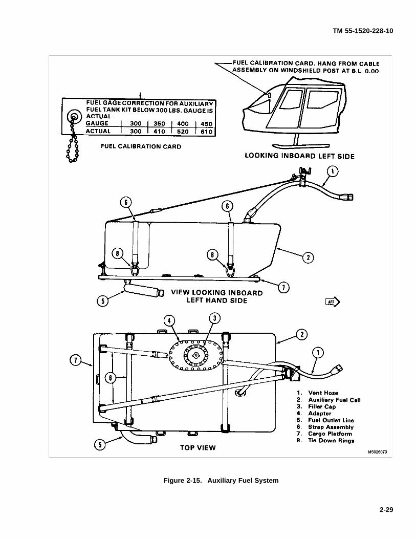
TM 55-1520-228-10
Figure 2-15. Auxiliary Fuel System
2-29
TM 55-1520-228-10
2-24. CONTROLS AND INDICATORS.
a. Fuel Quantity Indicator. The FUEL QTY indica-tor (f gure 2-13 and 2-14) is located in the instrumentpanel and displays the quantity of fuel in the fuel cell inpounds (0 to 600 lbs.). The indicator is powered by 28Vdc and protect by INST CLUSTER circuit breaker A.,FUEL QTY circuit breaker C..
b. Fuel Boost Caution Light. The FUEL BOOSTcaution light (f gure 2-13 and 2-14) is located on the cau-tion panel and illuminates if the fuel boost pressure isbelow safe operating limits when fuel boost switch is inthe ON position. The system is powered by 28 Vdc andprotected by CAUTION PANEL LTS circuit breaker.
c. Fuel Boost Pump Switch. The FUEL BOOSTswitch (f gure 2-13 and f gure 2-14) is located in thelower right corner of the instrument panel. The fuel boostswitch will be in the fuel boost position for all normalconditions when the engine is operating and for start-ing. The system is powered by 28 Vdc and protected byFUEL PUMP circuit breaker.
NOTE
Low fuel caution systems alert the pilot that fuelin the tank has reached a specif ed level (capac-ity). Differences in fuel densities due to temper-
ature and fuel type will vary the weight of fuelremaining and actual time aircraft engine mayoperate. Differences in fuel consumption rates,aircraft altitude and operational condition of thefuel subsystem will also affect actual time air-craft engine may operate.
d. Low Fuel Quantity Caution Light. The LOWFUEL caution light, (f gure 2-13 and f gure 2-14), lo-cated in caution panel, should illuminate when there isapproximately 20 minutes or 65 to 98 pounds of fuelremaining. The illumination of this light does not meana f xed time remains. When the 20 minute fuel cautionlight is on, the fuel remaining may not be availableexcept when the aircraft is in level or coordinated f ight.The 20 minute fuel caution light in conjunction with afuel boost caution light may indicate impending fuelstarvation. The system is powered by 28 VDC andprojected by Caution PNL LTS circuit breaker.
e. Fuel Filter Caution Light. The FUEL FILTERcaution light (f gure 2-13 and f gure 2-14), located in thecaution panel, will illuminate when the f lter in the fuelsupply line becomes partially obstructed. The systemis powered by 28 Vdc and protected by CAUTION PNLLTS circuit breaker. The light may illuminate momen-tarily when the boost pump is turned on, but it shouldextinguish within approximately ten seconds.
SECTION V FLIGHT CONTROLS
2-25. DESCRIPTION.
When carrying non-rated passengers unfamil-iar with operation of the helicopter, pilot shouldevaluate the mission as to advantages and dis-advantages of stowing copilot controls or ac-cepting the responsibility of the potential hazardwhen leaving the controls in place.
The f ight control system is a positive mechanical type,actuated by conventional helicopter controls which,when moved, directs the helicopter in various modesof f ight. Dual f ight controls are provided. The systemincludes; the cyclic control stick, used for fore and aftand lateral control; the collective pitch control lever,used for vertical control; and the tail rotor anti-torquecontrol pedals, used for heading control. The con-
trol forces of the main rotor f ight control system arereduced to a near zero pounds force, to lessen pilotfatigue, by hydraulic servo cylinders connected to thecontrol system mechanical linkage and powered bythe transmission driven hydraulic pump. Force trims(force gradients) connected to the cyclic controls areelectrically operated mechanical units used to induceartif cial control feeling into the cyclic controls and toprevent the cyclic stick moving from a pre-set position.
2-26. CYCLIC CONTROL.
The pilot cyclic grip (f gures 2-3 and 2-4) contains the fol-lowing switches: force trim release switch, ICS switch,and RADIO transmit switch. The cyclic control systemcontrols the fore, aft, and lateral movement of the heli-copter. Control feel is provided by the force trim units.
2-30 Change 14
TM 55-1520-228-10
NOTE
Removal of copilot cyclic stick can cause pilotcyclic stick to creep slightly aft.
a. Copilot Cyclic Stick Storage.
NOTE
Force trim will be lost when the electrical con-nector is disconnected when stowing or remov-ing the copilot cyclic stick. Removal is autho-rized by the pilot and/or commander (Fuel quan-tity gage cannot be monitored with cyclic stickstowed C.).
(1) Unscrew retaining nut on cyclic stick.
(2) Secure cyclic stick on stowage pin and straplocated on the left outboard side of the center console.
b. Copilot Cyclic Stick Installation.
(1) Remove cyclic stick from stowage.
(2) Insert cyclic stick into pivot assembly ontorque tube.
(3) Secure cyclic stick in pivot assembly withknurled nut.
(4) Ensure electrical connector is installed.
2-27. COLLECTIVE PITCH CONTROL.
Do not use deck under collective for storage.This could cause interference in the full downposition.
The pilot collective pitch control is located in the left ofthe pilot position and controls the vertical mode of f ight.A rotating grip-type throttle and a switch box assemblyare located in the forward end of the pilot collective pitchlever (f gure 2-3 and f gure 2-4). The switch box assem-bly contains the starter, governor engine idle releaseand landing lights switches. Friction can be induced intothe collective system by rotation a friction device locatedbetween the pilot and copilot seats. The copilot collec-tive lever, located on the left of the copilot position, con-
tains only a twist type throttle at the forward end of thecontrol.
a. Copilot Collective Pitch Control Stowage.
(1) Remove the boot around copilot stick shaft.
(2) Loosen knurled nut at base of copilot stick.Remove stick.
(3) Stow stick in clips located on forward side ofcopilot seat.
b. Copilot Collective Pitch Control Installation.
(1) Remove stick from stowage clips and insertstick in jackshaft elbow assuring engagement of throttletube.
(2) Secure stick in elbow with knurled nut.
(3) Secure boot around stick shaft.
2-28. ANTI-TORQUE (DIRECTION) CONTROL.
Anti-torque control pedals (f gure 2-3 and f gure 2-4) al-ter the pitch of the tail rotor blades and thereby providethe means of directional control. Pedal adjustments arelocated at the base of the pedals at f oor level. Adjusterknobs enable adjustment of pedal distance for individualcomfort.
a. Deleted.
b. Deleted.
2-29. FORCE TRIMS (FORCE GRADIENT).
Force gradient devices are incorporated in the controls.These devices are installed in the f ight control systembetween the cyclic stick and the hydraulic power cylin-der (servo). The devices act to furnish a force gradientof feel to the cyclic control stick. However, these forcescan be reduced to zero by depressing the force trim but-ton on the cyclic stick (f gure 2-3 and f gure 2-4). Thegradient is accomplished b means of springs and mag-netic brake release assemblies which enable the pilot totrim the controls, as desired, for any condition of f ight.A FORCE TRIM toggle switch is installed in the controlpanel to activate the force trim system.
Change 10 2-31
TM 55-1520-228-10
2-30. HORIZONTAL STABILIZER.
The horizontal stabilizer (f gure 2-1 and f gure 2-2) is lo-cated near the center of the tail boom an is installedin a predetermined f xed position. The horizontal sta-bilizer aids in trimming the helicopter in level f ight andincreases usable CG range.
2-31. VERTICAL FIN.
The vertical f n is located to the right of the tail rotor andis installed in a predetermined f xed position.
SECTION VI HYDRAULIC SYSTEM
2-32. DESCRIPTION.
The hydraulic system consists of a variable deliverypump and reservoir, servo actuators with irreversiblevalve circuits for cyclic and collective controls, a pres-sure line f lter, a return line f lter, and a solenoid shutoffvalve. The pump is located on the transmission. Thehydraulic system provides for fully powered f ight con-trols during authoritative f ight.
2-33. CONTROL.
A hydraulic system switch (HYD BOOST) is located onthe lower right portion of the instrument panel and con-trols the activation and deactivation of the hydraulic sys-tem. (Refer to f gure 2-13 and f gure 2-14.)
2-34. CAUTION INDICATOR.
A caution indicator is located on the caution panel toindicate when hydraulic pressure is low (f gure 2-13 andf gure 2-14).
2-32 Change 10
TM 55-1520-228-10
SECTION VII POWER TRAIN SYSTEM
2-35. TRANSMISSION.
The transmission is mounted on the cabin roof deck, for-ward of the power plant. The transmission transfers en-gine power to the main rotor through the mast assembly.The tail rotor is driven through the freewheeling unit, tailrotor driveshafts and tail rotor gearbox. Transmission lu-brication is provided by a pump, relief valves, two eachf lters, spray jets, temperature bulb, and an oil cooler.The pump is a constant volume type driven by the ac-cessory gear. An oil level sight gage is located on theright side of the transmission case. A breather type f llercap and two electrical magnetic chip detector drain plugsare incorporated. The transmission also furnishes lubri-cation for the freewheeling unit mounted in the engineaccessory gearbox. Transmission oil is cooled by the oilcooler blower.
2-36. PYLON SUPPORT STRUCTURE.
a. The OH-58A/C has a design feature called a fo-cused pylon mounting system for its pylon. This supportconcept differs from conventional four or f ve point springmounting arrangements as follows:
(1) The pylon bi-pod supports aim or focus py-lon input loads at the fuselage vertical center of gravity.The purpose is to reduce cabin vibration by eliminatingpylon induced rolling moment about the center of grav-ity.
(2) Rigid mounting in the vertical plane mini-mizes vertical vibration.
(3) Vibration should not increase with mount ag-ing as is possible with conventional spring mounted py-lon supports.
b. The elastomeric mount provides pylon staticcentering.
2-37. PYLON SUSPENSION SYSTEM.
a. The main transmission is supported and at-tached at its lower rear section by an isolation mount.Bolted to the lower rear section by an isolation mount.Bolted to the lower aft part of the transmission caseis the drag pin which bolts to the elastomeric isolationmount.
b. The drag pin has a metal pin which is commonlyreferred to as the spike. The drag pin or spike physically
is mounted so that “rides” inside the square metal open-ing of the transmission mount support.
c. The isolation mount is used to dampen pylon tofuselage vibration and limit pylon rock. Movement of thetransmission and isolation mount is limited by means ofthe drag pin (spike) which extends down into the trans-mission mount support mounted on the deck.
d. Contact between the drag pin and the transmis-sion mount produces a noise known as spike knock.
2-38. FREEWHEELING ASSEMBLY.
The freewheeling unit is mounted in the accessory gear-box. Engine power is transmitted through the freewheel-ing unit to the main driveshaft and tail rotor driveshaftsto provide power to the main and tail rotors respectively.During autorotation the freewheeling unit provides en-gine disconnect and the transmission drives the tail ro-tor.
2-39. TAIL ROTOR GEARBOX.
The gearbox is located near the vertical f n and providesa 90 degree change of direction of the tail rotor drive-shaft. A breather type f ller cap, electrical chip detectordrain plug and an oil level sight gage are provided.
2-40. DRIVESHAFTS.
a. Main Driveshaft. The main driveshaft connectsthe engine output to the transmission.
b. Tail Rotor Driveshaft. The tail rotor driveshaft ismade up of four sections; the forward short shaft, the oilcooler fan shaft, the aft short shaft, and the long shaft.
2-41. INDICATORS.
a. Transmission Chip Detectors. There are threechip detectors located within the transmission lubricat-ing system. Two electrical chip detectors are locatedon the base of the transmission and are wired to theXMSN CHIP DET caution light and the MASTER CAU-TION light. One magnetic chip detector is located onthe freewheeling unit and is not connected to the cautionlighting system. All three are provided to give evidenceof ferrous metal particles in the transmission lubricationsystem.
Change 11 2-33
TM 55-1520-228-10
b. Tail Rotor Gearbox Chip Detector. The chip de-tector is located in the lower section of the tail rotor gear-box. The chip detector is wired to the T/R CHIP DETcaution light and the MASTER CAUTION light. The cau-tion light is activated when a suff cient amount of metalparticles has been collected on the chip detector to closethe circuit.
c. Transmission Oil Pressure WarningLight. The XMSN OIL PRESS warning light (f gure2-13 and f gure 2-14) is located in the upper centersection A., and upper right corner C. of the instrumentpanel. The XMSN OIL PRESS light will illuminatesteady until oil pressure is above 36 psi. Normaloperating pressure is 30 to 60 psi with warning light
actuation at 30 ± 2 psi on decreasing pressure. Thetransmission oil pressure switch is located on the leftside of the cabin roof near the transmission. The lightis protected by the CAUTION PNL LTS circuit breaker.
d. Transmission Oil Temperature WarningLight. The XMSN OIL HOT warning light (f gure2-13 and f gure 2-14) is located in the upper centersection A., and upper right corner C. of the instrumentpanel. The XMSN OIL HOT light will illuminate steadyuntil oil temperature is below 110°C. The transmissionoil temperature sensor is located on the transmissionoil f lter head. The light is protected by the CAUTIONPNL LTS circuit breaker.
SECTION VIII MAIN AND TAIL ROTOR GROUPS
2-42. MAIN ROTOR.
The main rotor assembly is a two blade, semi-rigid, see-saw type rotor called an underslung feathering axis hub.The blades are mounted in the hub assembly grips withblade retaining bolts which have hollow shanks for in-stallation of weights to balance the hub and blade as-sembly. Pitch change and pillow block bearings are lu-bricated with grease. The rotor blades are all metal, con-sisting of an extruded aluminum alloy nose block, alu-minum alloy trailing edge and an aluminum honeycombf ller. The main rotor is driven by the mast which is con-nected to the transmission. The rotor RPM is governedby the engine RPM during powered f ight. The rotor tippath plane is controlled by the cyclic stick. The rotorpitch is controlled by the collective lever.
2-43. MAIN ROTOR RPM INDICATOR.
The same audio tone is used for both the rotorrpm warning and engine out warning. Check thevisual indicators to determine corrective actionnecessary.
The rotor tachometer indicator (f gure 2-13 A., f gure2-14 C.) is part of the dual tachometer and is locatedon the instrument panel. The rotor RPM reading isindicated on the inner scale and the pointer needleis marked with an R. The indicator is powered by a
tachometer generator mounted on and driven by thetransmission and is independent of the helicopter elec-trical system. C. Model aircraft require 28 VDC and areprotected by the DUAL TACH circuit breaker.
2-44. RPM WARNING SYSTEM.
A ROTOR RPM warning system is installed to providea visual and audio indication of low rotor RPM. A RPMsensor is connected to the rotor tachometer. Power issupplied from the CAUTION PNL LTS circuit breakerand connections are made to the ROTOR RPM warninglight and to a tone generator which provides an audibletone in the crews headsets. The warning system is ac-tivated when the rotor RPM drops below 95% ± 1.4%.
2-45. TAIL ROTOR.
The tail rotor is driven by the inner shaft of the freewheel-ing unit through tail rotor driveshaft and the tail rotorgearbox. The tail rotor hub and blade assembly consistsof an aluminum alloy forged yoke and aluminum alloyblades. The spherical bearings provide for pitch changeof the blades. The hub and blade assembly are mountedon the tail rotor gearbox shaft by means of a splined trun-nion, mounted in bearings in the yoke, to provide a f ap-ping axis for the assembly. The tail rotor gearbox hasa breather type f lter cap, electrical chip detector and oillevel sight gage, all accessible from ground level. Tailrotor blade pitch is controlled by the anti-torque pedals.
2-34 Change 11
TM 55-1520-228-10
SECTION IX UTILITY SYSTEM
2-46. PITOT HEATING SYSTEM.
a. Description. The pitot heater is installed on thepitot head and functions to prevent ice forming in thepitot tube. Electric power for the pitot heater operationis supplied from the 28 VDC helicopter electrical sys-tem. Circuit protection is provided by a 5 ampere cir-
cuit breaker switch on the overhead console. The pitotheater is controlled by a switch located on the overheadconsole (f gure 2-12) labeled PITOT HTR.
b. Operation. The pitot heater switch should be inPITOT HTR position to prevent ice forming in pitot tube.To shut off pitot heater, position switch to OFF.
SECTION X HEATING AND VENTILATION
2-47. BLEED AIR HEATING SYSTEM.
a. Description. The bleed air heater is installed inthe equipment compartment aft of the electrical shelf be-hind the passenger seat. A HTR switch (f gure 2-12) lo-cated on the overhead console actuates the heater. Thepilot may select air temperature by means of a HEATcontrol knob (f gure 2-17) located above and aft of hishead. This knob operates a control cable in the cabinroof to adjust an air temperature sensor mounted in theheater discharge duct. Adjusting the sensor mixes thefresh and bleed air to obtain the air temperature selectedby the pilot. The bleed air heating ducts are connectedto windshield defog nozzles at the bottom of the for-ward windshield through blowers mounted in the fuse-lage nose. The blowers are activated by DEFOG &VENT circuit breaker switch (f gure 2-12) located on theoverhead console to increase airf ow velocity over thewindshield. Lower nose window defog is continuous andautomatic when HTR switch is turned on. Outside freshair from an intake on the top of the fuselage nose is di-rected through the windshield defog nozzles mountedon the lower windshield frame. A VENT PULL controlon the right side of the instrument panel (f gure 2-16)opens and closes the fresh air intake.
b. Operation A circuit breaker switch labeled HTRon the overhead console (f gure 2-12) actuates a sole-
noid valve. The switch in the ON position permits airfrom the engine compressor section to pass through thebleed air nozzle. A venturi working in conjunction withthe bleed air nozzle draws in outside air through the out-side air vent. Bleed air and outside air is fed into themixing valve where a sensor determines the mixing ra-tio produce the desired temperature. Bleed air forcesheated air through the duct system to registers underthe seat and/or to the defroster nozzles. Temperatureis regulated by a manual control knob labeled HEAT lo-cated above and to the rear of the pilot’s head, and con-nected to a variable remote sensor in the heater com-partment. The sensor has a bimetallic element whichcontrols the mixing valve. The defogging and vent sys-tem is installed in the nose and consists of a ram air in-take, two blower fans, defroster nozzles and ducts. Thebleed air system is also connected to the defogging andvent system. Outside air f ow to the cabin and defoggingnozzles is controlled by manual push-pull type controlslabeled VENT and DEFOG located on each side of theinstrument panel (f gure 2-16). The blowers direct air tothe defogging nozzles and are controlled by a 5 AMPcircuit breaker switch, labeled DEFOG & VENT, on theoverhead console. (Refer to f gure 2-12.)
Change 10 2-35
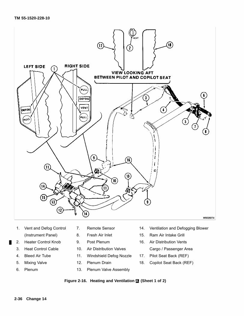
TM 55-1520-228-10
1. Vent and Defog Control 7. Remote Sensor 14. Ventilation and Defogging Blower
(Instrument Panel) 8. Fresh Air Inlet 15. Ram Air Intake Grill
2. Heater Control Knob 9. Post Plenum 16. Air Distribution Vents
3. Heat Control Cable 10. Air Distribution Valves Cargo / Passenger Area
4. Bleed Air Tube 11. Windshield Defog Nozzle 17. Pilot Seat Back (REF)
5. Mixing Valve 12. Plenum Drain 18. Copilot Seat Back (REF)
6. Plenum 13. Plenum Valve Assembly
Figure 2-16. Heating and Ventilation A. (Sheet 1 of 2)
2-36 Change 14
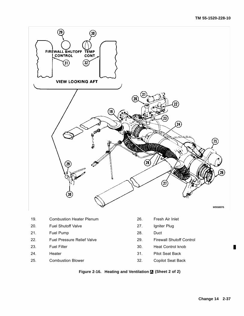
TM 55-1520-228-10
19. Combustion Heater Plenum 26. Fresh Air Inlet
20. Fuel Shutoff Valve 27. Igniter Plug
21. Fuel Pump 28. Duct
22. Fuel Pressure Relief Valve 29. Firewall Shutoff Control
23. Fuel Filter 30. Heat Control knob
24. Heater 31. Pilot Seat Back
25. Combustion Blower 32. Copilot Seat Back
Figure 2-16. Heating and Ventilation A. (Sheet 2 of 2)
Change 14 2-37
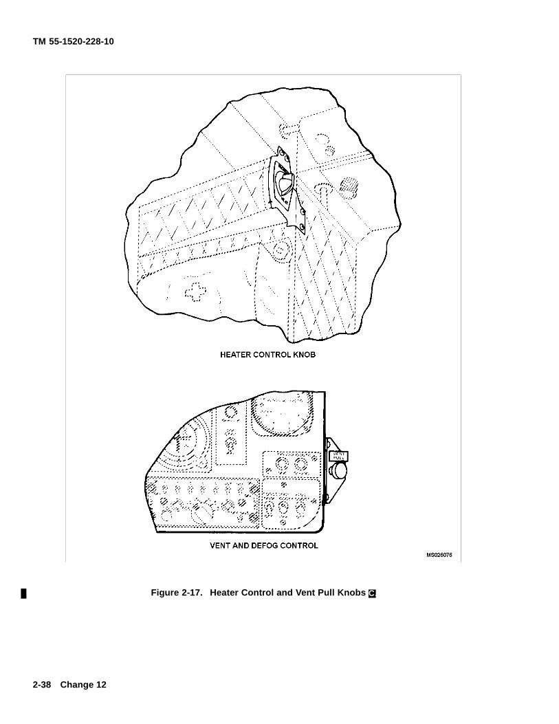
TM 55-1520-228-10
Figure 2-17. Heater Control and Vent Pull Knobs C.
2-38 Change 12
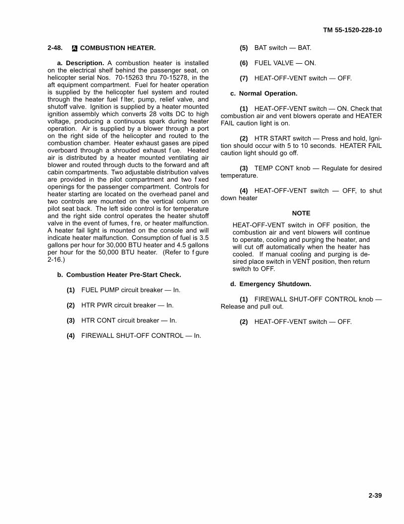
TM 55-1520-228-10
2-48. A. COMBUSTION HEATER.
a. Description. A combustion heater is installedon the electrical shelf behind the passenger seat, onhelicopter serial Nos. 70-15263 thru 70-15278, in theaft equipment compartment. Fuel for heater operationis supplied by the helicopter fuel system and routedthrough the heater fuel f lter, pump, relief valve, andshutoff valve. Ignition is supplied by a heater mountedignition assembly which converts 28 volts DC to highvoltage, producing a continuous spark during heateroperation. Air is supplied by a blower through a porton the right side of the helicopter and routed to thecombustion chamber. Heater exhaust gases are pipedoverboard through a shrouded exhaust f ue. Heatedair is distributed by a heater mounted ventilating airblower and routed through ducts to the forward and aftcabin compartments. Two adjustable distribution valvesare provided in the pilot compartment and two f xedopenings for the passenger compartment. Controls forheater starting are located on the overhead panel andtwo controls are mounted on the vertical column onpilot seat back. The left side control is for temperatureand the right side control operates the heater shutoffvalve in the event of fumes, f re, or heater malfunction.A heater fail light is mounted on the console and willindicate heater malfunction. Consumption of fuel is 3.5gallons per hour for 30,000 BTU heater and 4.5 gallonsper hour for the 50,000 BTU heater. (Refer to f gure2-16.)
b. Combustion Heater Pre-Start Check.
(1) FUEL PUMP circuit breaker — In.
(2) HTR PWR circuit breaker — In.
(3) HTR CONT circuit breaker — In.
(4) FIREWALL SHUT-OFF CONTROL — In.
(5) BAT switch — BAT.
(6) FUEL VALVE — ON.
(7) HEAT-OFF-VENT switch — OFF.
c. Normal Operation.
(1) HEAT-OFF-VENT switch — ON. Check thatcombustion air and vent blowers operate and HEATERFAIL caution light is on.
(2) HTR START switch — Press and hold, Igni-tion should occur with 5 to 10 seconds. HEATER FAILcaution light should go off.
(3) TEMP CONT knob — Regulate for desiredtemperature.
(4) HEAT-OFF-VENT switch — OFF, to shutdown heater
NOTE
HEAT-OFF-VENT switch in OFF position, thecombustion air and vent blowers will continueto operate, cooling and purging the heater, andwill cut off automatically when the heater hascooled. If manual cooling and purging is de-sired place switch in VENT position, then returnswitch to OFF.
d. Emergency Shutdown.
(1) FIREWALL SHUT-OFF CONTROL knob —Release and pull out.
(2) HEAT-OFF-VENT switch — OFF.
2-39

TM 55-1520-228-10
SECTION XI ELECTRICAL POWER SUPPLY AND DISTRIBUTIONSYSTEM
2-49. DIRECT CURRENT PRIMARY POWER.
The OH-58A/C helicopter is equipped with a 28-volt di-rect current dual bus (essential and non-essential) sys-tem supplied by a starter-generator and battery (f gure2-18). Components of the direct current power systeminclude battery, starter-generator, voltage regulator, re-lays, switches, and circuit breakers. All circuits in theelectrical system are single wire with common groundreturn. The negative terminals of the starter-generatorand the battery are grounded to the helicopter struc-ture. In the event of generator failure, with the NON-ESSBUS switch in the NORM position, the non-essential busis automatically deactivated. The battery then suppliespower to the essential bus load. The non-essentail busmay be manually reactivated by placing the NON-ESSBUS to the MAN position. In the event of engine failure,generator power will be lost.
a. Indicators and Controls.
(1) DC System Indicator. The ammeter ismounted in the instrument cluster on the instrumentpanel and indicates the ampere load being used. Thecircuit is protected by two circuit breakers, labeledLOADMETER in the aft electrical compartment.
(2) DC Power Control. The DC power is con-trolled by the BAT switch, GEN switch, NON-ESS BUSswitch, and circuit breakers labeled GEN & BUS RESETand GEN FIELD.
(3) Battery Switch. The Battery switch is lo-cated in the overhead console and is a two-positiontoggle switch, labeled BAT and OFF. Battery electricalpower is supplied to the helicopter electrical systemwhen the switch is in the BAT position. When the switchis in the BAT position, it closes the circuit to the actu-ating coil of the battery relay and battery power is thendelivered from the battery to the essential bus. Whenthe switch is placed in the OFF position, it opens thecircuit to the actuating coil of the battery relay and nopower is delivered from the battery to the essential bus.
(4) Generator Switch. The generator switch islocated on the overhead console and is a three-position
switch. This switch is labeled GEN in the forward posi-tion, OFF in the center position, and RESET in the aftposition. The RESET position is spring-loaded to returnto the OFF position when released. Therefore, to resetthe generator, the switch must be held in RESET posi-tion momentarily, and then moved to the forward posi-tion.
(5) Non-Essential Bus Switch. The non-es-sential bus switch is located in the overhead consoleand is a two-position switch labeled NON-ESS BUSNORM and MAN. When the switch is in the NORMposition, power is supplied to the non-essential bus pro-vided the generator is operating or when external poweris applied. When the switch is in the MAN position,power is supplied to the non-essential bus regardlessof generator operation.
b. Circuit Breakers. The DC circuit breaker panel(f gure 2-12) is located in the overhead console. Eachindividual circuit breaker is clearly labeled for particu-lar electrical circuits protected. In the event a circuit isoverloaded, the circuit breaker protecting that circuit willdeactivate. The circuit is reactivated by pushing the cir-cuit breaker button.
c. External Power Receptacle. During ground op-erations, external power may be connected to the elec-trical system through an external power receptacle lo-cated on the lower right side of the helicopter just aftof the rear landing gear crosstube. The GEN and BATswitches should be in the OFF position when externalpower is connected. The external power relay closesautomatically and connects the ground unit to the es-sential and non-essential buses. A GPU power of 300to 750 amperes and 28 vdc is recommended.
d. Auxiliary Power Receptacle. The auxiliarypower receptacle is mounted on a bulkhead aft of thecopilot seat and provides power take off of 28 Vdc tooperate miscellaneous auxiliary equipment. The circuitis powered by 28 Vdc essential bus and is controlledand protected by AUX RECP circuit breaker switch onthe overhead console.
2-40 Change 10
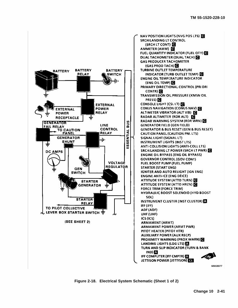
TM 55-1520-228-10
Figure 2-18. Electrical System Schematic (Sheet 1 of 2)
Change 10 2-41
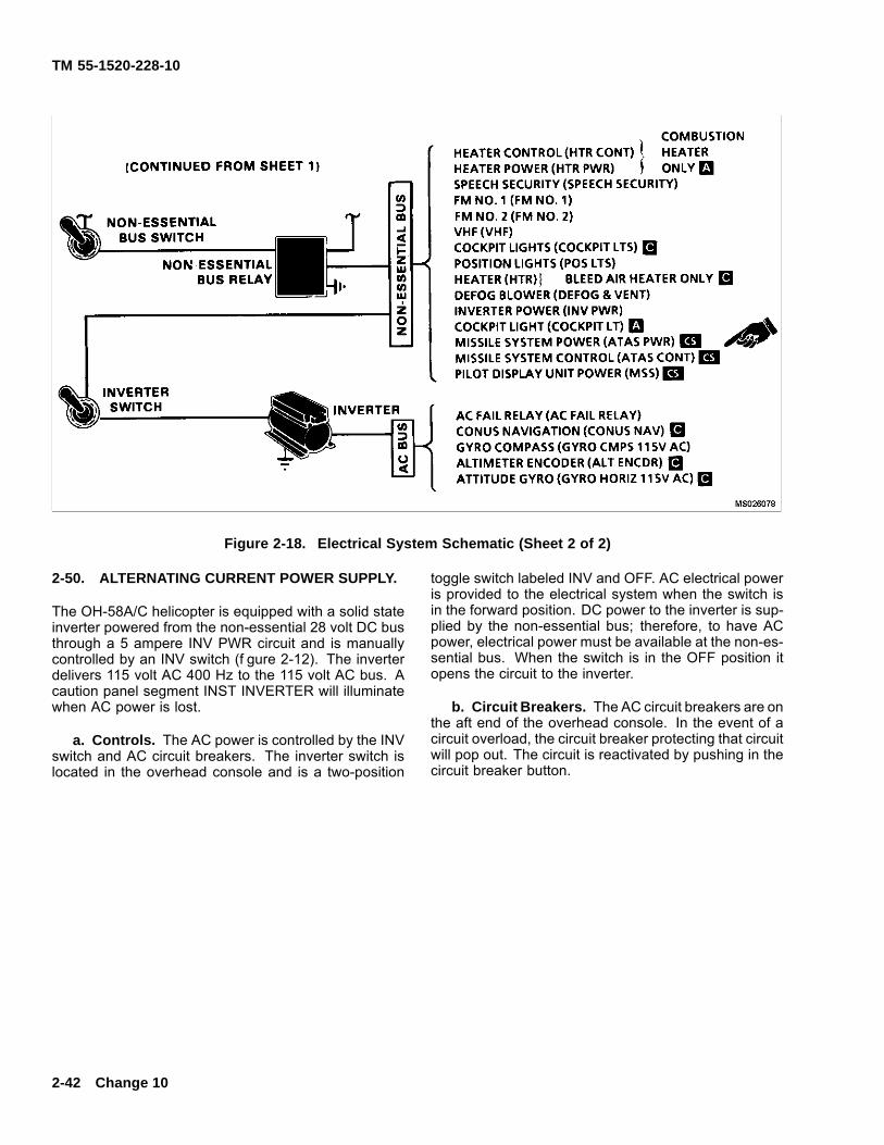
TM 55-1520-228-10
Figure 2-18. Electrical System Schematic (Sheet 2 of 2)
2-50. ALTERNATING CURRENT POWER SUPPLY.
The OH-58A/C helicopter is equipped with a solid stateinverter powered from the non-essential 28 volt DC busthrough a 5 ampere INV PWR circuit and is manuallycontrolled by an INV switch (f gure 2-12). The inverterdelivers 115 volt AC 400 Hz to the 115 volt AC bus. Acaution panel segment INST INVERTER will illuminatewhen AC power is lost.
a. Controls. The AC power is controlled by the INVswitch and AC circuit breakers. The inverter switch islocated in the overhead console and is a two-position
toggle switch labeled INV and OFF. AC electrical poweris provided to the electrical system when the switch isin the forward position. DC power to the inverter is sup-plied by the non-essential bus; therefore, to have ACpower, electrical power must be available at the non-es-sential bus. When the switch is in the OFF position itopens the circuit to the inverter.
b. Circuit Breakers. The AC circuit breakers are onthe aft end of the overhead console. In the event of acircuit overload, the circuit breaker protecting that circuitwill pop out. The circuit is reactivated by pushing in thecircuit breaker button.
2-42 Change 10
TM 55-1520-228-10
SECTION XII LIGHTING
2-51. POSITION LIGHTS.
The position lights consist of three lights (f gure 2-1 andf gure 2-2). A green light is located on the right horizon-tal stabilizer tip, a red light on the left horizontal stabilizertip, and a white light on the aft end of the tailboom. Elec-trical power is supplied from the 28-volt DC non-essen-tial bus. Circuit protection is provided by the POS LTScircuit breaker on the overhead console. The positionlights are controlled by the POS LTS switch on the over-head console (f gure 2-12). The switch is a three-posi-tion toggle switch with BRT (forward) DIM (center) andOFF (aft) positions.
2-52. NVG POSITION LIGHTS.
Five, white IR position lights (NVG position lights) aremounted on the aircraft. Two forward NVG positionlights (f gure 2-2) are mounted forward of the FM hom-ing antenna on both sides of the aircraft. Two lowerNVG position lights (f gure 2-2) are mounted forwardof the APR-39 antenna support. One aft NVG positionlight is located on top of the tail light support assembly.Power for NVG position lights is provided by the NVGPOS LTS circuit breaker (f gure 2-12). Operation ofthe NVG position lights is controlled by a f ve-positionrotary switch, NVG POS LTS, (f gure 2-12) located onthe overhead console. In position 1, the lights are atminimum intensity, in position BRT, the lights are atmaximum intensity.
2-53. ANTI-COLLISION LIGHTS.
The anti-collision lights are located one on top of the en-gine cowling and one centered at the lower section ofthe fuselage aft of the avionics compartment. Electri-cal power for the anti-collision lights is provided by the28-volt DC electrical system essential bus. The anti-collision light switch is located on the overhead con-sole (f gure 2-12). The switch is a two-position toggletype labeled ANTI-COLLISION LTS and OFF. The for-ward position energizes the anti-collision light circuit.
Float equipped helicopters have lower light relocatedfrom boom station 88.0 to boom station 103.0.
2-54. LANDING LIGHTS.
IR/White (Dual) Landing/Searchlight. A dual light as-sembly with a white light on one side and IR light on theother side is mounted in the lower nose section of thehelicopter (f gure 2-2).
Do not illuminate IR light with light assemblyfully retracted. Doing so may cause light tooverheat, resulting in damage to electrical com-ponents of the helicopter.
Power for the light assembly is provided by the SRCHLT CONT and SRCH LT PWR circuit breakers. Onethree-position switch and one four-position switch, co-lo-cated on the pilot collective lever (f gure 2-4), are usedto operate the light assembly.
DELETED
The three-position switch LDG LT (ON-NVG-OFF) con-trols illumination of the white light (ON position) and theIR light (NVG position).
NOTE
White light will automatically extinguish whenlight rotates 90° right or left of center, if extendedless than 60°.
The four-position switch LDG LT (EXT-RETR-L-R) pro-vides extension, 360° rotation and retraction.
Change 12 2-43
TM 55-1520-228-10
2-55. DELETED.
2-56. INSTRUMENT LIGHTS.
The instrument lights are all on one circuit and are con-trolled by a rheostat switch labeled INST LTS on theoverhead console (f gure 2-12). Clockwise rotation ofthe rheostat knob activates the instrument panel circuitand increases brilliance. Counterclockwise rotation ofthe knob dims, with f nal movement (OFF) deactivatingthe electrical circuit from the essential bus.
NVG compatible bezel lights and postlights provideinstrument panel lighting (f gure 2-4). The instrumentpanel lighting is controlled by the INST LT rheostatcontrol (f gure 2-12) and is powered by the INST LTScircuit breaker.
2-57. CONSOLE LIGHTS.
The console lights are all on one circuit, and are con-trolled by a rheostat switch labeled CONSOLE LTS onthe overhead console (f gure 2-12). Clockwise rotationof the rheostatknob activates the console panel circuitand increases brilliance. Counterclockwise rotation ofthe knob dims, with f nal movement (OFF) deactivatingthe circuit, located on the essential bus.
a. Night Vision Features (for Flights Using NightVision Goggles (NVG)). A hinged light f lter is attachedto the instrument panel so it can be adjusted over theROTOR RPM warning light of the warning panel (f gure
2-13, items 8 and 9) for f ights using NVG, and adjustedaway from the ROTOR RPM warning light for f ights notusing NVG. A hinged light f lter is also attached to theinstrument panel for the other warning lights, and mastercaution lights for use in the same manner.
b. NVG-compatible panel lights provide lighting ofthe ICS boxes KY28 and the ADF REVR located in theaircraft. The console lighting is controlled by the CON-SOLE LT rheostat (f gure 2-12) and is powered by theCSL LT circuit breaker.
2-58. SIGNAL LIGHT RECEPTACLE.
A plug-in type receptacle (f gure 2-12) for a hand heldsignal light, is located at the aft end of the overheadconsole. Power is supplied from the essential bus.
2-59. COCKPIT UTILITY LIGHT.
a. Cockpit Utility Lights. Two cockpit utility lightsare located within easy reach of either crew member.One is located on the center post and the other on theoverhead center beam behind the copilot. One has alight f lter for use with f ights using NVG when necessary.The lights may be hand held or positioned in their holderfor direct beam direction. A rheostat switch is part ofeach light assembly. Power is supplied from the non-essential bus through the COCKPIT LTS circuit breaker.
b. Supplementary NVG-compatible cockpit lightingis provided by a utility light and three f oodlights. The
2-44 Change 12
TM 55-1520-228-10
utility light is attached to a f exible gooseneck extensionmounted on the centerpost between the pilot and copi-lot seats (f gure 2-4). The f exible gooseneck holds theutility light in the position selected by the pilot or copilot.An extension cord allows removal of the utility light fromthe gooseneck for manual use. The light is equippedwith a self-contained rheostat and has a rheostat over-ride push button that provides full lamp output regard-less of knob setting. Power for the light is provided bythe COCKPIT LTS circuit breaker. Three NVG-compat-ible f oodlights are mounted on the glareshield (f gure2-4). Floodlight intensity is controlled by the CONSOLELT rheostat. The f oodlights are powered by CSL LTScircuit breaker (f gure 2-12).
2-60. NVG-COMPATIBLE FILTERS.
NVG-compatible f ip f lters are to remain in theopen position (unf ltered) during day f ight andnight f ight without night vision goggles.
NVG-compatible f ip f lters are mounted next to the mas-ter caution, caution advisory, RPM, and radar warningindicators (f gure 2-13 and f gure 2-14). The f lters arepositioned closed for NVG f ight only.
SECTION XIII FLIGHT INSTRUMENTS
2-61. AIRSPEED INDICATOR.
The airspeed indicator (f gure 2-13 and f gure 2-14) dis-plays the air speed of the helicopter indicated in knots.The airspeed is obtained by measuring the differencebetween impact air pressure from the pitot tube and thestatic air pressure from the static ports.
2-62. AAU-31 / A PNEUMATIC ALTIMETER.
1. Description. The AAU-31/A pneumatic counter-drum-pointer altimeter is a precision pressure altimeter(f gure 2-14). Pressure altitude is displayed by a 100-foot drum and a single pointer indicating hundreds offeet on a circular scale, with 50’ center markings. Belowan altitude of 10,000 feet, a diagonal warning symbol willappear on the 10,000-foot counter.
A barometric pressure setting knob is provided to in-sert the desired altimeter setting in inches of Hg. A DCpowered vibrator operates inside the altimeter wheneveraircraft power is on.
2. Operation
a Normal Operation. The ALT VIB C. or ALTAAU 31/32A A. circuit breaker must be in. The altimeterindicates pneumatic altitude reference to the baromet-ric pressure level as selected by the pilot. A vibrator,powered by the DC essential bus, is contained in the al-timeter and requires a minimum of one minute warmupprior to checking or setting the altimeter.
b Abnormal Operation. If the altimeter’s inter-nal vibrator becomes inoperative due to internal failureof DC power failure, the pointer and drum may momen-tarily hang up when passing from “9” through “0” (climb-ing) or from “0” through “9” (descending). This hang-upwill cause lag, the magnitude of which will depend on thevertical velocity of the aircraft and the friction in the al-timeter. Pilots should be especially watchful for this typefailure when the minimum approach altitude lies withinthe “8” — “1” part of the scale (800-100, 1800-2100,etc.).
2-62.1. ALTITUDE ENCODER/PNEUMATICALTIMETER AAU-32/A
a. Description. The AAU-32/A pneumatic counter-drum-pointer altimeter is a self-contained unit whichconsists of a precision pressure altimeter combinedwith an altitude encoder (f gure 2-18.1). The displayindicates and the encoder transmits, simultaneously,pressure altitude reporting. Altitude is displayed onthe altimeter by a 10,000 foot counter, a 1,000 footcounter and a 100 foot drum. A single pointer indicateshundreds of feet of a circular scale, with 50 foot centermarkings. Below an altitude of 10,000 foot a diagonalwarning system will appear on the 10,000 foot counter.A barometric pressure setting knob is provided to insertthe desired altimeter setting in inches of Hg. A DCpowered vibrator operates in-
Change 4 2-45
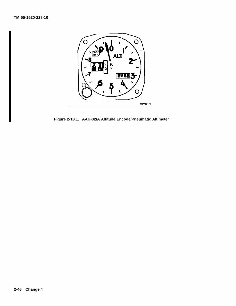
TM 55-1520-228-10
Figure 2-18.1. AAU-32/A Altitude Encode/Pneumatic Altimeter
2-46 Change 4
TM 55-1520-228-10
side the altimeter whenever the aircraft power is on. Thevibrator is powered through the ALT AAV31/32A[A] orALT VIB[C] circuit breaker. The encoder is DC pow-ered with the vibrator through the ALT AAU31/32A circuitbreaker [A] or separately AC powered through the ALTENCDR circuit breaker [C]. If power to the altitude en-coder is lost, a warning f ag placarded CODE OFF willappear in the upper left portion of the instrument face in-dicating that the altitude encoder is inoperative and thatthe system is not reporting altitude to ground stations.The CODE OFF f ag monitors only the encoder functionof the altimeter. It does not indicate transponder condi-tion. The altitude reporting function may be inoperativewithout the AAU-32/A CODE OFF f ag showing, in caseof the transponder failure or improper control settings.It is also possible to get a “good” MODE C test on thetransponder control with the CODE OFF f ag showing.Display of the CODE OFF f ag only indicates an encoderpower failure or a CODE OFF f ag failure. In this event,check that encoder power is available and that the circuitbreakers are in. If the f ag is still visible, radio contractshould with a ground radar site to determine whether thealtitude reporting function is operative, and the remain-der of the f ight should be conducted accordingly.
b. Operation.
(1) Normal Operation. The ALT AAU31/32[A]or ALT VIB and ALT ENCDR[C] circuit breakers shouldbe in prior to f ight. The Mode C switch (M-C) on thetransponder control should be switched to ON for al-titude reporting during f ight. The AAU-32/A altimeterindicates pneumatic altitude reference to the barometricpressure level as selected by the pilot. At ambientpressure, altimeters should agree with ±70 feet of thef eld elevation when the proper barometric pressuresetting is set in the altimeter. A red f ag marked CODEOFF is located in the upper left portion of the altimetersface. In order to supply Mode C information to the IFFtransponder, the CODE OFF f ag must not be visible. Avibrator, powered by the DC essential bus, is containedin the altimeter and requires a minimum of one minutewarm up prior to checking or setting the altimeter.
(2) Abnormal Operation.
(a) If the altimeters internal vibrator becomesinoperative due to internal failure of DC power failure,the pointer and drum may momentarily hang-up when
passing from 9 through 0 (climbing) or from 0 through 9(descending). This hang-up will cause lag, the magni-tude of which will depend on the vertical velocity of theaircraft and the friction in the altimeter.
(b) If the CODE OFF f ag is visible, the en-coder power is not available, the circuit breaker is notin, or there is an internal altimeter encoder failure.
(c) If the altimeter indicator does not corre-spond within 70 feet of the f eld elevation (with properlocal barometric setting) the altimeter needs rezeroingor there has been an internal failure.
(d) If the baroset knob binds or sticks, abnor-mal force should not be used to make the setting as thismay cause internal gear failure resulting in altitude er-rors. Settings can sometimes be made by backing offand turning at a slower rate.
2-63. PRESSURE ALTIMETER.
NOTE
Not applicable after MWO 55-1520-228-50-24is applied.
A. The pressure altimeter (f gure 2-13) furnishes directreadings of height above mean sea level when properlyadjusted.
2-64. ATTITUDE INDICATOR.
A. The attitude indicator (f gure 2-13) displays the atti-tude of the helicopter. the indicator is self contained andis connected through circuit breakers on the overheadconsole to the 115-volt AC bus.
C. The attitude indicator (f gure 2-14) displays the he-licopter pitch and roll attitudes in relation to the earthhorizon. Pitch attitude is displayed by the motion of thesphere with respect to the miniature airplane. Roll atti-tude is displayed by the motion of the roll pointer withrespect to the f xed roll scale. The sphere can be ad-justed to zero indication by the pitch trim knob. The rateof turn pointer indicates in which direction and at whatrate the helicopter is turning. The inclinometer indicateswhen the helicopter is in trim, either in a coordinated turn
Change 11 2-46.1
TM 55-1520-228-10
or in straight and level f ight. The warning f ag, atti-tude (ATT) and rate of turn pointer provide indication ofsystem malfunctions. When the gyro is being caged orwhen 28 Vdc power is interrupted, the ATT f ag will bein full view. The rate of turn pointer will be biased outof view when 28 Vdc is interrupted. The circuit is pow-ered by 28 Vdc essential bus and protected by ATTDHRZN and ATTN TURN circuit breakers. The rate-of-turn pointer is driven by 115 VAC internal circuitry thatderives rate-of-turn from the output synchro transmitterof the directional gyro magnetic compass.
2-65. TURN AND SLIP INDICATOR.
A. The turn and slip indicator (f gure 2-13) is controlledby a direct current electrically actuated gyro. This in-strument has a needle (turn indicator) and a ball (slipindicator). Although needle and ball are combined inone instrument and are normally read and interpretedtogether, each has its own specif c function and oper-ates independently of the other. The ball indicates whenthe helicopter is in directional balance either in a turn orin straight and level f ight. If the helicopter is yawing orslipping, the ball will be off center. The needle indicatesin which direction and at what rate the helicopter is turn-ing.
2-66. FREE AIR TEMPERATURE INDICATOR.
The bi-metal free air temperature indicator (f gure 2-13and f gure 2-14) is in the windshield, and provides a di-rect reading of the outside air temperature.
2-67. MAGNETIC COMPASS.
The magnetic compass (f gure 2-13 and f gure 2-14)is a standard, non-stabilized, magnetic type instrumentmounted on a support which is attached to the right sideof the cabin structure forward of the pilot. The compassis used in conjunction with a compass correction cardthat is located near the compass. In aircraft with low re-f ective painted interior, the compass correction card willbe located in the front of the logbook.
2-68. VERTICAL SPEED INDICATOR.
The vertical speed indicator (f gure 2-13 and f gure 2-14)displays the helicopter ascent and descent speed in feetper minute. the indicator is actuated by the rate of atmo-spheric pressure change.
2-69. C. CONUS NAVIGATION SYSTEM(AN/ARN-123).
Refer to Chapter 3.
2-70. RADAR ALTIMETER (AN/APN-209).
Refer to Chapter 3.
2-71. RADAR WARNING SYSTEM.
Refer to Chapter 3.
2-72. MISCELLANEOUS INDICATORS.
Instruments and indicators that are independent or arelinked with more than one system are the clock and mas-ter caution and warning system (f gure 2-12).
a. Clock. The clock (f gure 2-13 and f gure 2-14)has a sweep-second pointer and a minute totalizer handto indicate elapsed time. The control knob in the upperright corner of the case starts, stops, and returns thepointers to the 12 o’clock position when actuated.
b. Caution System. The caution system (f gure2-13 and f gure 2-14) is a segment wording type, con-sisting of a segment word warning CAUTION panel(f gure 2-19) on the lower console and a remote MAS-TER CAUTION segment on the instrument panel. Thepurpose of the CAUTION system is to provide visualindication suitable for day or night operation, that afault condition has occurred. In addition, a positivesignal is provided to illuminate the remote MASTERCAUTION indicator. Each fault condition, as it occurs, isindicated by A., f ashing of the lettering on the segmentinvolved and by a f ashing of the MASTER CAUTIONindicator. C., steady illumination of the lettering on thesegment involved and by a steady illumination of theMASTER CAUTION indicator. A momentary position-ing of RESET-TEST switch to RESET extinguishes theMASTER CAUTION light so that it will illuminate forthe next fault indication; also, the fault segment will besteadily ON. Segments will remain lighted as long asthe fault condition(s) exist. Momentarily pressing theRESET-TEST switch to TEST will check if all cautionlightsare operational. Testing of the system will notchange the existing fault conditions. The BRIGHT-DIM
2-46.2 Change 14
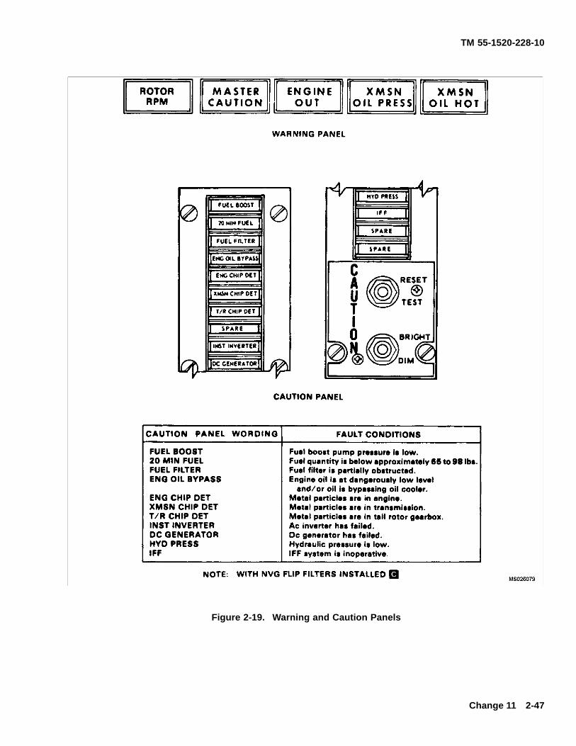
TM 55-1520-228-10
Figure 2-19. Warning and Caution Panels
Change 11 2-47
TM 55-1520-228-10
switch (f gure 2-19) controls the brightness of the cautionpanel lights and the MASTER CAUTION light. The INSTLTS switch must be moved from the DIM position beforethe caution panel lights can be dimmed. The system isso designed that after each initial application of power,the lamps will illuminate in the bright condition.
c. Warning System. The warning system consistsof f ve individually illuminated warning light segmentsmounted in the MASTER CAUTION and warning lightpanel (f gure 2-19) on the instrument panel. The pur-pose of this system is to provide visual indication for dayor night operation that any of the f ve conditions or com-binations thereof has occurred. Each fault condition asit occurs is indicated by a steady illumination of the let-tering on the particular segment. In addition, an audiosignal sounds when the ENGINE OUT or ROTOR RPMsegment is illuminated and the collective pitch is not inthe full down position. The warning indicator segmentremains illuminated until the fault condition is corrected.
ENGINE OUT Engine N1 speed below 55± 3%.
XMSN OIL PRESS Transmission oil pressuredangerously low.
XMSN OIL HOT Transmission dangerouslyhot.
ROTOR RPM Rotor rpm low.MASTER CAUTION Fault condition in caution
panel.
The WARNING LTS TEST switch (f gure 2-13 and f g-ure 2-14) is pressed to check for illumination of all thewarning lights.
SECTION XIV SERVICING, PARKING, AND MOORING
2-73. SERVICING.
a. Servicing Diagram. Refer to f gure 2-20 and f g-ure 2-21.
b. Fuels, Oils, Fluids, Speci cations, and Capac-ities. Refer to table 2-1.
2-74. APPROVED FUELS, OILS, AND FLUIDS.
a. Fuels. Refer to table 2-2.
b. Oils. Refer to table 2-3.
c. Fluids. Refer to table 2-4.
2-75. FUEL TYPES. See table 2-2.
a. JP-4. This fuel contains icing inhibitor blended atthe ref nery. Commercial Jet B is a JP-4 type fuel; itsmixture may or may not contain icing inhibitors.
b. JP-5 and JP-8. These fuels contain icing in-hibitors blended at the ref nery. Jet A and Jet A1 areJP-5 type fuels without icing inhibitors.
c. Emergency Fuel. Aviation gasolines (MIL-G-5572) without Tricresyl Phosphate (TCP) are desig-nated as the emergency fuels to be used in this aircraft.
2-76. USE OF FUELS.
a. JP-4. There is no special limitation on the use ofJP-4 fuel, but limitations are imposed when fuels otherthan JP-4 are used.
b. JP-5, JP-8, Jet A, and Jet A1. These fuels maybe added to JP-4 and to each other in any quantities.
c. Emergency Fuels. Aviation gasoline may alsobe added to turbine engine fuels in any quantity. Fuelmixtures containing any amount of Aviation Gasolinemust be recorded in the Remark Section of DA Form2408-13-1 as an emergency fuel, noting the type of fuel,additives, and duration of operation. The 6 hour totalengine operation limitation applies.
d. Refer to fuel operation limits, Chapter 5, whenfuels other than JP-4 are used.
2-48 Change 11
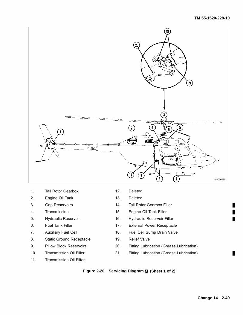
TM 55-1520-228-10
1. Tail Rotor Gearbox 12. Deleted
2. Engine Oil Tank 13. Deleted
3. Grip Reservoirs 14. Tail Rotor Gearbox Filler
4. Transmission 15. Engine Oil Tank Filler
5. Hydraulic Reservoir 16. Hydraulic Reservoir Filler
6. Fuel Tank Filler 17. External Power Receptacle
7. Auxiliary Fuel Cell 18. Fuel Cell Sump Drain Valve
8. Static Ground Receptacle 19. Relief Valve
9. Pillow Block Reservoirs 20. Fitting Lubrication (Grease Lubrication)
10. Transmission Oil Filler 21. Fitting Lubrication (Grease Lubrication)
11. Transmission Oil Filter
Figure 2-20. Servicing Diagram A. (Sheet 1 of 2)
Change 14 2-49
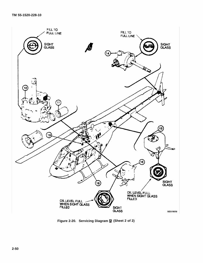
TM 55-1520-228-10
Figure 2-20. Servicing Diagram A. (Sheet 2 of 2)
2-50
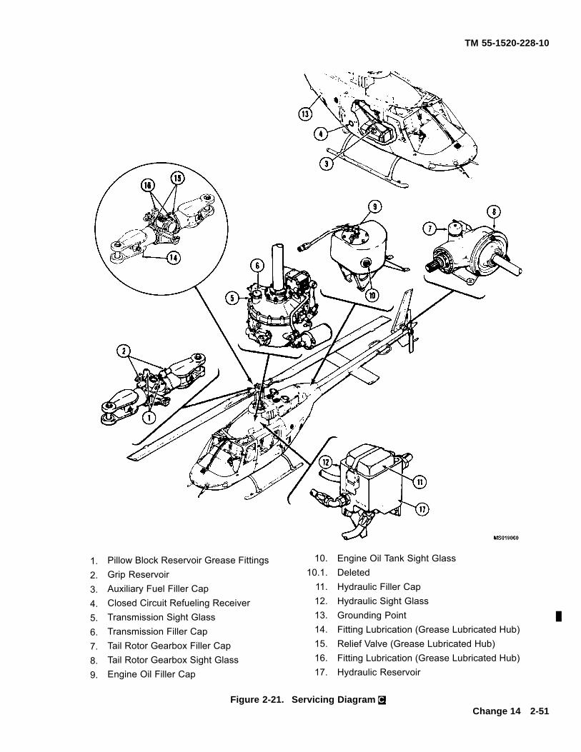
TM 55-1520-228-10
1. Pillow Block Reservoir Grease Fittings 10. Engine Oil Tank Sight Glass
2. Grip Reservoir 10.1. Deleted
3. Auxiliary Fuel Filler Cap 11. Hydraulic Filler Cap
4. Closed Circuit Refueling Receiver 12. Hydraulic Sight Glass
5. Transmission Sight Glass 13. Grounding Point
6. Transmission Filler Cap 14. Fitting Lubrication (Grease Lubricated Hub)
7. Tail Rotor Gearbox Filler Cap 15. Relief Valve (Grease Lubricated Hub)
8. Tail Rotor Gearbox Sight Glass 16. Fitting Lubrication (Grease Lubricated Hub)
9. Engine Oil Filler Cap 17. Hydraulic Reservoir
Figure 2-21. Servicing Diagram C.Change 14 2-51

TM 55-1520-228-10
Table 2-1. Fuels, Oils, Fluids, Speci cations, and Capacities
SYSTEM SPECIFICATION CAPACITY
Fuel(Note 1)
MIL-T-5624 (JP-4)MIL-T-5624 (JP-5)MIL-T-83133 (JP-8)MIL-G-5572 (without TCP) Emergency Fuel
71.5 U.S. Gal(70.3 usable)
Fuel(Auxiliary FuelCell)(Note 1)
MIL-T-5624 (JP-4) MIL-T-5624 (JP-5) MIL-T-83133 (JP-8) MIL-G-5572(without TCP) Emergency Fuel
23.9 U.S. Gal
If DOD-L-85734 oil is added to any turbine engine or enginelubricated gearboxes, the engine/gearbox should be drainedand f ushed with proper lubricant when it becomes available.
*Lubrication oil made to MIL-L-7808 by Shell Oil Company un-der their part number 307, qualif cation number 7D-1, shall notbe used in OH-58A/C engine or helicopter systems. It containsadditives which are harmful to seals in the systems.
Engine Oil(Note 2) *MIL-L-7808 NATO Code is 0-148 For use in ambient temperaturesbelow minus 32°C/25° FMIL-L-23699 NATO Code is 0-156 For use in ambient temperaturesabove minus 32°C/25° F
11.2 U.S. Pt
*Lubrication oil made to MIL-L-7808 by Shell Oil Company un-der their part number 307, qualif cation number 7D-1, shall notbe used in OH-58A/C engine or helicopter systems. It containsadditives which are harmful to seals in the systems.
TransmissionOil(Note 2)
*MIL-L-7808 NATO Code is 0-148 For use in ambient temperaturesbelow minus 32°C/25° F MIL-L-23699 NATO Code is 0-156For use inambient temperatures above minus 32°C/25° FDOD-L-85734 for usein ambient temperatures above -40°C/40°F
4.0 U.S. Qts.
2-52 Change 7
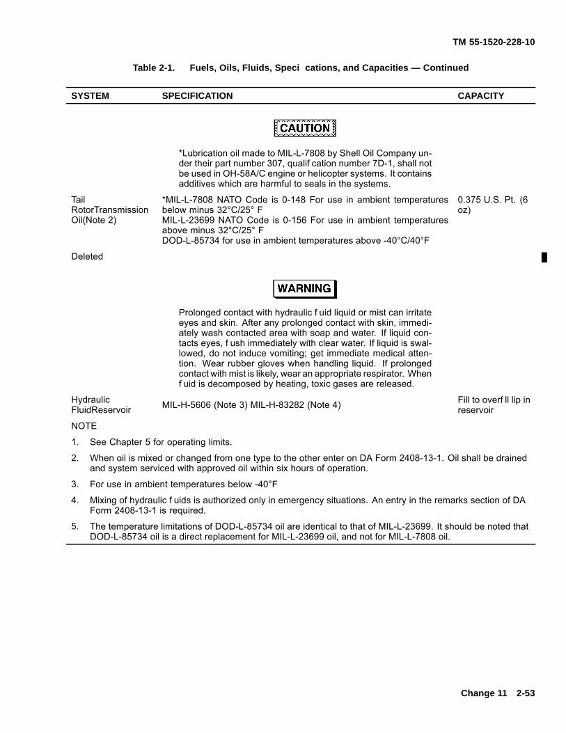
TM 55-1520-228-10
Table 2-1. Fuels, Oils, Fluids, Speci cations, and Capacities — Continued
SYSTEM SPECIFICATION CAPACITY
*Lubrication oil made to MIL-L-7808 by Shell Oil Company un-der their part number 307, qualif cation number 7D-1, shall notbe used in OH-58A/C engine or helicopter systems. It containsadditives which are harmful to seals in the systems.
TailRotorTransmissionOil(Note 2)
*MIL-L-7808 NATO Code is 0-148 For use in ambient temperaturesbelow minus 32°C/25° FMIL-L-23699 NATO Code is 0-156 For use in ambient temperaturesabove minus 32°C/25° FDOD-L-85734 for use in ambient temperatures above -40°C/40°F
0.375 U.S. Pt. (6oz)
Deleted
Prolonged contact with hydraulic f uid liquid or mist can irritateeyes and skin. After any prolonged contact with skin, immedi-ately wash contacted area with soap and water. If liquid con-tacts eyes, f ush immediately with clear water. If liquid is swal-lowed, do not induce vomiting; get immediate medical atten-tion. Wear rubber gloves when handling liquid. If prolongedcontact with mist is likely, wear an appropriate respirator. Whenf uid is decomposed by heating, toxic gases are released.
HydraulicFluidReservoir MIL-H-5606 (Note 3) MIL-H-83282 (Note 4) Fill to overf ll lip in
reservoir
NOTE
1. See Chapter 5 for operating limits.
2. When oil is mixed or changed from one type to the other enter on DA Form 2408-13-1. Oil shall be drainedand system serviced with approved oil within six hours of operation.
3. For use in ambient temperatures below -40°F
4. Mixing of hydraulic f uids is authorized only in emergency situations. An entry in the remarks section of DAForm 2408-13-1 is required.
5. The temperature limitations of DOD-L-85734 oil are identical to that of MIL-L-23699. It should be noted thatDOD-L-85734 oil is a direct replacement for MIL-L-23699 oil, and not for MIL-L-7808 oil.
Change 11 2-53
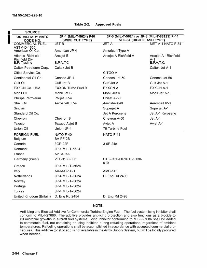
TM 55-1520-228-10
Table 2-2. Approved Fuels
SOURCEUS MILITARY NATO
CODE NO.JP-4 (MIL-T-5624) F40
(WIDE CUT TYPE)JP-5 (MIL-T-5624) or JP-8 (MIL-T-83133) F-44
or F-34 (HIGH FLASH TYPE)COMMERCIAL FUELASTM-D-1655
JET B JET A MET A-1 NATO F-34
American Oil Co. American JP-4 American Type AAtlantic Richf eldRichf eld Div
Arcojet B Arcojet A Richf eld A Arcojet A-1Richf eldA-1
B.P. Trading B.P.A.T.C B.P.A.T.K.Caltex Petroleum Corp. Caltex Jet B Caltek Jet A-1Cities Service Co. CITGO AContinental Oil Co. Conoco JP-4 Conoco Jet-50 Conoco Jet-60Gulf Oil Gulf Jet B Gulf Jet A Gulf Jet A-1EXXON Co. USA EXXON Turbo Fuel B EXXON A EXXON A-1Mobil Oil Mobil Jet B Mobil Jet A Mobil Jet A-1Phillips Petroleum Philjet JP-4 Philjet A-50Shell Oil Aeroshell JP-4 Aeroshell640 Aeroshell 650Sinclair Superjet A Superjet A-1Standard Oil Co. Jet A Kerosene Jet A-1 KeroseneChevron Chevron B Chevron A-50 Jet A-1Texaco Texaco Avjet B Avjet A Avjet A-1Union Oil Union JP-4 76 Turbine Fuel
FOREIGN FUEL NATO F-40 NATO F-44Belgium BA-PF-2BCanada 3GP-22F 3-6P-24eDenmark JP-4 MIL-T-5624France Air 3407AGermany (West) VTL-9139-006 UTL-9130-007/UTL-9130-
010Greece JP-4 MIL-T–5624Italy AA-M-C-1421 AMC-143Netherlands JP-4 MIL-T–5624 D. Eng Rd 2493Norway JP-4 MIL-T–5624Portugal JP-4 MIL-T–5624Turkey JP-4 MIL-T–5624United Kingdom (Britain) D. Eng Rd 2454 D. Eng Rd 2498
NOTE
Anti-icing and Biocidal Additive for Commercial Turbine Engine Fuel – The fuel system icing inhibitor shallconform to MIL-I-27686. The additive provides anti-icing protection and also functions as a biocide tokill microbial growths in aircraft fuel systems. Icing inhibitor conforming to MIL-I-27686 shall be addedto commercial fuel, not containing an icing inhibitor, during refueling operations, regardless of ambienttemperatures. Refueling operations shall be accomplished in accordance with accepted commercial pro-cedures. This additive (prist or ec.) is not available in the Army Supply System, but will be locally procuredwhen needed.
2-54 Change 7
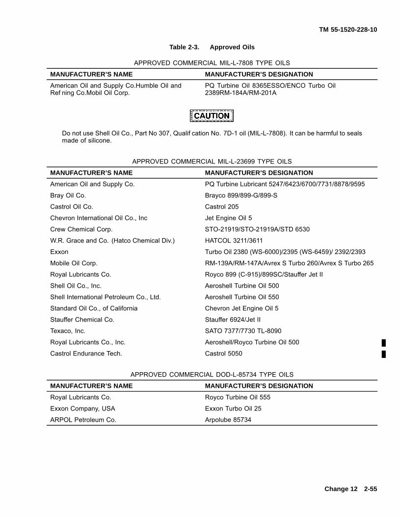
TM 55-1520-228-10
Table 2-3. Approved Oils
APPROVED COMMERCIAL MIL-L-7808 TYPE OILS
MANUFACTURER’S NAME MANUFACTURER’S DESIGNATION
American Oil and Supply Co.Humble Oil andRef ning Co.Mobil Oil Corp.
PQ Turbine Oil 8365ESSO/ENCO Turbo Oil2389RM-184A/RM-201A
Do not use Shell Oil Co., Part No 307, Qualif cation No. 7D-1 oil (MIL-L-7808). It can be harmful to sealsmade of silicone.
APPROVED COMMERCIAL MIL-L-23699 TYPE OILS
MANUFACTURER’S NAME MANUFACTURER’S DESIGNATION
American Oil and Supply Co. PQ Turbine Lubricant 5247/6423/6700/7731/8878/9595
Bray Oil Co. Brayco 899/899-G/899-S
Castrol Oil Co. Castrol 205
Chevron International Oil Co., Inc Jet Engine Oil 5
Crew Chemical Corp. STO-21919/STO-21919A/STD 6530
W.R. Grace and Co. (Hatco Chemical Div.) HATCOL 3211/3611
Exxon Turbo Oil 2380 (WS-6000)/2395 (WS-6459)/ 2392/2393
Mobile Oil Corp. RM-139A/RM-147A/Avrex S Turbo 260/Avrex S Turbo 265
Royal Lubricants Co. Royco 899 (C-915)/899SC/Stauffer Jet II
Shell Oil Co., Inc. Aeroshell Turbine Oil 500
Shell International Petroleum Co., Ltd. Aeroshell Turbine Oil 550
Standard Oil Co., of California Chevron Jet Engine Oil 5
Stauffer Chemical Co. Stauffer 6924/Jet II
Texaco, Inc. SATO 7377/7730 TL-8090
Royal Lubricants Co., Inc. Aeroshell/Royco Turbine Oil 500
Castrol Endurance Tech. Castrol 5050
APPROVED COMMERCIAL DOD-L-85734 TYPE OILS
MANUFACTURER’S NAME MANUFACTURER’S DESIGNATION
Royal Lubricants Co. Royco Turbine Oil 555
Exxon Company, USA Exxon Turbo Oil 25
ARPOL Petroleum Co. Arpolube 85734
Change 12 2-55
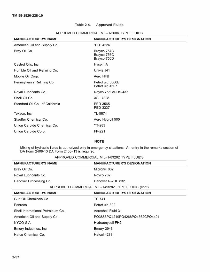
TM 55-1520-228-10
Table 2-4. Approved Fluids
APPROVED COMMERCIAL MIL-H-5606 TYPE FLUIDS
MANUFACTURER’S NAME MANUFACTURER’S DESIGNATION
American Oil and Supply Co. “PO” 4226
Bray Oil Co. Brayco 757BBrayco 756CBrayco 756D
Castrol Oils, Inc. Hyspin A
Humble Oil and Ref ning Co. Univis J41
Mobile Oil Corp. Aero HFB
Pennsylvania Ref ning Co. Petrof uid 5606BPetrof uid 4607
Royal Lubricants Co. Royco 756C/DDS-437
Shell Oil Co. XSL 7828
Standard Oil Co., of California PED 3565PED 3337
Texaco, Inc. TL-5874
Stauffer Chemical Co. Aero Hydroil 500
Union Carbide Chemical Co. YT-283
Union Carbide Corp. FP-221
NOTE
Mixing of hydraulic f uids is authorized only in emergency situations. An entry in the remarks section ofDA Form 2408-13 DA Form 2408–13 is required.
APPROVED COMMERCIAL MIL-H-83282 TYPE FLUIDS
MANUFACTURER’S NAME MANUFACTURER’S DESIGNATION
Bray Oil Co. Micronic 882
Royal Lubricants Co. Royco 782
Hanover Processing Co. Hanover R-2HF 832
APPROVED COMMERCIAL MIL-H-83282 TYPE FLUIDS (cont)
MANUFACTURER’S NAME MANUFACTURER’S DESIGNATION
Gulf Oil Chemicals Co. TS 741
Penreco Petrof uid 822
Shell International Petroleum Co. Aeroshell Fluid 31
American Oil and Supply Co. PQ3883PQ4219PQ4268PQ4362CPQ4401
NYCO S.A. Hydraunycoil FH2
Emery Industries, Inc. Emery 2946
Hatco Chemical Co. Hatcol 4283
2-57

TM 55-1520-228-10
Table 2-4. Approved Fluids — Continued
Prolonged contact with liquid or mist can irritate eyes and skin. After any prolonged contact with skin,immediately wash contacted area with soap and water. If liquid contacts eyes, f ush immediately withclear water. If liquid is swallowed, do not induce vomiting; get immediate medical attention. Wear rubbergloves when handling liquid. If prolonged contact with mist is likely, wear an appropriate respirator. Whenf uid is decomposed by heating, toxic gases are released.
NOTE
Mixing of hydraulic f uids is authorized only in emergency situations. An entry in the Remarks Section ofDA Form 2408-13 is required.
Table 2-4.1 HAS BEEN DELETED.
Change 11 2-57
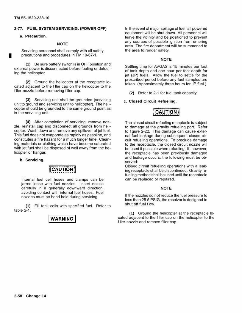
TM 55-1520-228-10
2-77. FUEL SYSTEM SERVICING. (POWER OFF)
a. Precaution.
NOTE
Servicing personnel shall comply with all safetyprecautions and procedures in FM 10-67-1.
(1) Be sure battery switch is in OFF position andexternal power is disconnected before fueling or defuel-ing the helicopter.
(2) Ground the helicopter at the receptacle lo-cated adjacent to the f ller cap on the helicopter to thef ller-nozzle before removing f ller cap.
(3) Servicing unit shall be grounded (servicingunit to ground and servicing unit to helicopter). The heli-copter should be grounded to the same ground point asis the servicing unit.
(4) After completion of servicing, remove noz-zle, reinstall cap and disconnect all grounds from heli-copter. Wash down and remove any spillover of jet fuel.This fuel does not evaporate as rapidly as gasoline, andconstitutes a f re hazard for a much longer time. Clean-ing materials or clothing which have become saturatedwith jet fuel shall be disposed of well away from the he-licopter or hangar.
b. Servicing.
Internal fuel cell hoses and clamps can bejarred loose with fuel nozzles. Insert nozzlecarefully in a generally downward direction,avoiding contact with internal fuel hoses. Fuelnozzles must be hand held during servicing.
(1) Fill tank cells with specif ed fuel. Refer totable 2-1.
In the event of major spillage of fuel, all poweredequipment will be shut down. All personnel willleave the vicinity and be positioned to preventany sources of possible ignition from enteringarea. The f re department will be summoned tothe area to render safety.
NOTE
Settling time for AVGAS is 15 minutes per footof tank depth and one hour per foot depth forjet (JP) fuels. Allow the fuel to settle for theprescribed period before any fuel samples aretaken. (Approximately three hours for JP fuel.)
(2) Refer to 2-1 for fuel tank capacity.
c. Closed Circuit Refueling.
The closed circuit refueling receptacle is subjectto damage at the gravity refueling port. Referto f gure 2-22. This damage can cause exter-nal fuel leakage during subsequent closed cir-cuit refueling operations. To preclude damageto the receptacle, the closed circuit nozzle willbe used if possible when refueling. If, however,the receptacle has been previously damagedand leakage occurs, the following must be ob-served:Closed circuit refueling operations with a leak-ing receptacle shall be discontinued. Gravity re-fueling method shall be used until the receptaclecan be replaced or repaired.
NOTE
If the nozzles do not reduce the fuel pressure toless than 25.5 PSIG, the receiver is designed toshut off fuel f ow.
(1) Ground the helicopter at the receptacle lo-cated adjacent to the f ller cap on the helicopter to thef ller-nozzle and remove f ller cap.
2-58 Change 14
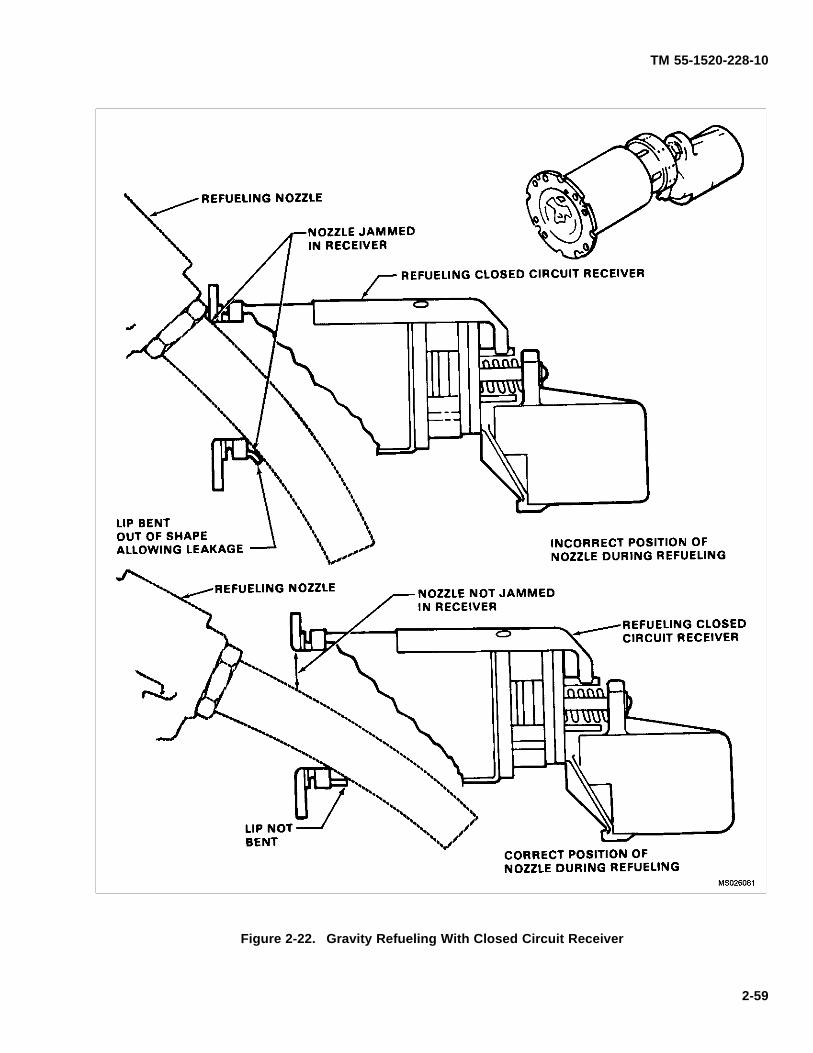
TM 55-1520-228-10
Figure 2-22. Gravity Refueling With Closed Circuit Receiver
2-59
TM 55-1520-228-10
(2) Ensure that gravity refueling port is closed.If not, rotate inner sleeve counterclockwise until gravityrefueling port is closed and f ange of sleeve is in contactwith rivet at base or receiving cylinder. Refer to f gure2-23.
Ensure that servicing unit pressure is not above125 PSI while refueling.
(3) Insert fueling nozzle into receiver and actu-ate automatic nozzle lever to ON or FLOW position. Pinat base of nozzle will momentarily indicate when fuelf ow stops.
(4) Fuel f ow will automatically shut off whennormal fuel level is reached. Just prior to normal shutoff, fuel f ow may cycle several times as fuel level isreached. Gage on servicing unit will indicate when f owis stopped.
(5) When fuel f ow has stopped, actuate leveron nozzle to OFF, disconnect nozzle from receiver andreplace f ller cap.
(6) Disconnect fuel nozzle ground and rewindhose assembly.
(7) Disconnect servicing unit ground at heli-copter.
(8) Disconnect servicing unit ground at ground-ing stake.
If helicopter is equipped with closed circuitrefueling system and fuel servicing unit is notequipped with related nozzle for closed circuitrefuelling, a gravity system may be used pro-viding the servicing nozzle does not exceed1.75 inches outside diameter. To refuel utilizingthe gravity nozzle, it is necessary to positionthe inner sleeve of receiver until slot is linedup with fuel port in bottom of receiver. Positionnozzle into port in order to bypass closed cir-cuit refueling system if caution is not used toprevent damage to inner sleeve of receiver atfuel port through improper use of nozzle.
d. Gravity Refueling.
(1) Ground the helicopter at the receptacle lo-cated adjacent to the f ller cap on the helicopter to thef ller-nozzle and remove f ller cap.
(2) Rotate inner sleeve clockwise until sleeveclears port in bottom of fuel receiver. Refer to f gure2-23.
(3) Position nozzle into port of fuel receiver.
(4) Fill to specif ed level.
(5) Remove nozzle and rotate inner sleevecounterclockwise until gravity refueling port is closedand f ange of inner sleeve is in contact with rivet at baseof receiver cylinder.
(6) Reinstall f ller cap.
(7) Disconnect fuel nozzle ground and rewindhose.
(8) Disconnect servicing unit ground at heli-copter.
(9) Disconnect servicing unit ground at ground-ing stake.
2-78. FUEL SYSTEM SERVICING. (RAPID (HOT)REFUELING).
When it is determined that rapid (hot) refuel-ing is required (prescribed in FM 10-68), propergrounding of aircraft must be accomplished.
a. Precautions.
NOTE
Servicing personnel shall comply with all safetyprecautions and procedures in FM 10-68 FM10–68.
NOTE
If the nozzles do not reduce the fuel pressure toless than 25.5 PSIG, the receiver is designed toshut off fuel f ow.
(1) Ground the helicopter at the receptacle lo-cated adjacent to the f ller cap on the helicopter to thef ller-nozzle before removing f ller cap.
2-60 Change 12
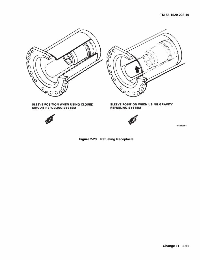
TM 55-1520-228-10
Figure 2-23. Refueling Receptacle
Change 11 2-61
TM 55-1520-228-10
(2) Servicing unit shall be grounded (servicingunit to ground and servicing unit to helicopter). The heli-copter should be grounded to the same ground point asis the servicing unit.
(3) After completion of servicing, remove noz-zle, reinstall cap, and disconnect all grounds from heli-copter.
b. Servicing.
(1) Fill tank cells with specif ed fuel. Refer totable 2-1.
(2) Refer to table 2-1 for fuel tank capacity.
c. Before Rapid (Hot) Refueling:
Only emergency radio transmission should bemade during rapid refueling. In case of air-craft f re, observe f re emergency procedures inChapter 9. Do not attempt to f y the aircraft.
(1) Minimum crew will remain at the controls.
(2) Throttle — Idle.
(3) Force Trim — ON or controls frictioned.
(4) Passengers shall depart the aircraft and re-main clear of the helicopter.
(5) No smoking allowed during refueling opera-tions.
(6) A crew member, if available, should observethe refueling operation (performed by authorized refuel-ing personnel) and stand f re guard as required.
d. During Rapid (Hot) Refueling.
(1) Closed Circuit Refueling.
(a) Ground the helicopter at the receptaclelocated adjacent to the f ller cap on the helicopter to thef ller-nozzle and remove f ller cap.
(b) Ensure that gravity refueling port isclosed. If not, rotate inner sleeve counterclockwise until
gravity refueling port is closed and f ange of sleeve is incontact with rivet at base of receiver cylinder. Refer tof gure 2-23.
Ensure that servicing unit pressure is not above125 PSI while refueling.
(c) Insert fueling nozzle into receiver and ac-tuate automatic nozzle lever to ON or FLOW position.Pin at base of nozzle will momentarily indicate when fuelf ow stops.
(d) Fuel f ow will automatically shut off whennormal fuel level is reached. Just prior to normal shut off,fuel f ow may cycle several times as fuel level is reached.Gage on servicing unit will indicate when f ow is stopped.
(e) When fuel f ow has stopped, actuate leveron nozzle to OFF, disconnect nozzle from receiver andreplace f ller cap.
(f) Disconnect fuel nozzle ground and rewindhose assembly.
(g) Disconnect servicing unit ground at heli-copter.
(h) Disconnect servicing unit ground atgrounding stake.
If helicopter is equipped with closed circuitrefueling system and fuel servicing unit is notequipped with related nozzle for closed circuitrefueling, a gravity system may be used provid-ing the servicing nozzle does not exceed 1.75inches outside diameter. To refuel utilizing thegravity nozzle, it is necessary to position theinner sleeve of receiver until slot is lined up withfuel port in bottom of receiver. Position nozzleinto port in order by bypass closed circuit valve.Damage could result to the closed circuit refu-eling system if caution is not used to preventdamage to inner sleeve of receiver at fuel portthrough improper use of nozzle.
2-62
TM 55-1520-228-10
(2) Gravity Refueling.
(a) Ground helicopter at receptacle locatedadjacent to f ller cap on helicopter to f ller-nozzle andremove f ller cap.
(b) Rotate inner sleeve clockwise until sleeveclears port in bottom of fuel receiver. Refer to f gure2-23.
(c) Position nozzle into port of fuel receiver.
(d) Fill to specif ed level.
(e) Remove nozzle and rotate inner sleevecounterclockwise until gravity refueling port is closedand f ange of inner sleeve is in contact with rivet at baseof receiver cylinder.
(f) Reinstall f ller cap.
(g) Disconnect fuel nozzle ground andrewind hose.
(h) Disconnect fuel nozzle ground andrewind hose.
(i) Disconnect servicing unit ground atgrounding stake.
e. After Rapid Refueling.
(1) The pilot shall be advised by the refuelingcrew that fuel cap(s) are secure and ground cable havebeen removed.
(2) Crew members and passengers can enteraircraft.
f. Defueling and Draining.
(1) Remove fuel cap; rotate inner sleeve clock-wise until end of sleeve clears port in bottom of fuel re-ceiver.
(2) Insert a suction pickup from a defueler vehi-cle into fuel f ller opening and remove all possible fuel.
(3) To complete defueling, drain remaining fuelinto a suitable container by opening fuel cell sump drain.
2-79. ENGINE OIL SYSTEM SERVICING.
An engine high oil level coupled with a transmis-sion low oil level condition indicates a possiblefailure of engine gearbox seal(s) which is allow-ing oil to transfer from the transmission throughthe freewheeling unit.
Engine oil tank is located aft of engine and oil cooler fan.Oil level is checked by a “trapped ball” sight gage on tank(f gure 2-20 and f gure 2-21). Ball must be seen f oatingin oil for safe oil level. Refer to table 2-1 for authorizedoil.
2-80. TRANSMISSION AND GEARBOX OILSYSTEM SERVICING.
a. Transmission. A sight glass located on trans-mission housing (f gure 2-20 and f gure 2-21) is usedto check oil level in transmission. Oil level must be vis-ible in sight glass. If oil is visible, additional oil is notrequired. If oil is not visible in sight glass, add oil to cen-ter dot only. Refer to table 2-1 for authorized oil.
b. Gearbox. A sight glass is provided for ease inchecking oil level. Refer to table 2-1 for authorized oil.Fill to the line for standard gear. Fill to 1/8-inch belowline when high gear or f oats are installed.
2-81. HYDRAULIC SYSTEM SERVICING.
The hydraulic reservoir (f gure 2-20 and f gure 2-21) islocated on forward side of transmission. A sight glasswith ball f oat or line level is provided to determine lowquantity of f uid in reservoir. Fill to overf ow lip in reser-voir. Refer to table 2-1 for authorized f uid.
2-82. BLADE GRIPS AND PILLOW BLOCKSSERVICING.
Grease Lubricated Hub. Blade grips and pillow blockson main rotor hub are lubricated with grease throughlubrication f ttings. The grips have a relief valve locatedon each pitch horn.
Change 12 2-63
TM 55-1520-228-10
2-83. GROUND HANDLING.
Towing. Tow rings are provided on forward inboard por-tion of each landing gear skid (f gure 2-24) for attach-ment of a standard aircraft tow bar. Helicopter is towedon ground handling wheel assemblies mounted on thelanding skids.
2-84. PARKING.
a. Retract ground handling wheels and allow heli-copter to rest on skid type landing gear.
b. Install main rotor blade tie-down (f gure 2-24).
c. Install engine air inlet shield assemblies in en-gine inlets and covers on engine exhausts.
2-85. COVERS.
a. Engine Inlet and Pitot Tube. An engine inlet andpitot cover (f gure 2-24) is provided to prevent entranceof dust etc., into engine inlet and pitot system when he-licopter is parked. When stowed in helicopter, stow en-gine inlet shields and pitot covers securely in helicoptercabin only.
b. Engine Exhaust. Individual covers (f gure 2-24)are provided for exhaust stacks to prevent entrance offoreign objects into engine exhaust when helicopter isparked. When stowed in helicopter, stow engine ex-haust covers securely in helicopter cabin only.
c. Main Rotor Tie-Down.
NOTE
Ensure strap side of main rotor tie-down boot ison top side of blade and drain hole is positionedat bottom of blade.
A rotor tie-down (f gure 2-24) is provided for use inmooring the aft main rotor blade. The tie-down preventsthe rotor from see-sawing when the helicopter is parked.When stowed in helicopter, stow rotor tie-down securelyin helicopter cabin only.
2-86. MOORING.
Structural damage can occur from f ying objectsduring high wind conditions. Helicopter shouldbe hangared or evacuated to a safe weatherarea when wind conditions above 50 knots areexpected.
The mooring hardware is to be carried in the f y-away kit. Flying the OH-58 with mooring hard-ware installed may result in damage to aircraft’shoneycomb surface. Retain all installation hard-ware together for each separate OH-58A/C he-licopters; due to wear, the bushings may not beinterchangeable. For additional information, re-fer to TM 1-1500-250-23-1.
a. If a paved ramp with suitable tie-down rings isavailable, position the aircraft on the mooring pad withthe longitudinal centerline of the aircraft directly aboveand parallel to longitudinal axis of pad as shown in f gure2-25. The forward mooring rings are to be located 5 feet4 inches aft of f rst mooring point as shown.
NOTE
It will be necessary to attach a mooring cle-vis to each of the three jack/mooring points.The clevis provided with the aircraft will not belarge enough to accept the hooks on the moor-ing chains provided with mooring pad. Mooringrings are to be installed on aircraft as shown inf gure 2-25.
b. Place the hook-ends of mooring chains into theappropriate clevis rings. Adjust the chains using the ad-justing devices provided on the mooring pad. Chainsshould be adjusted to a point where the slack has beenremoved.
c. If suitable spaced ramp tie-downs are not avail-able, park the helicopter on an unpaved parking areaheaded in the direction from which the highest forecastwinds are expected and retract ground handling wheels.Use mooring anchors to make “dead man” anchors.Moor helicopter as described in step a.
2-64 Change 10
TM 55-1520-228-10
2-86.1. ROTOR BLADE TIE-DOWN.
Secure the tie-down ropes carefully. Do notdamage the skin by f ipping the strap weightsaround the tailboom.
NOTEEnsure that strap side of main rotor tie-downboot is on top side of blade and drain hole ispositioned at bottom of blade.
a. To tie-down the aft blade, securely tie the strapsof the boot to the 1/2 inch polyester rope near the boot.Ensure the ropes are long enough to cross and tie inposition.
b. The forward blade shall also be tied down us-ing the same boot strap/rope arrangement device. Theropes shall be routed between the base and side sup-port struts of the forward lower cutter and tied at the rearof the base. In the f nal tie-position the blades must bein a level position.
c. Install covers on pitot tube, engine exhaust, andengine inlets.
d. An alternate method of installing pitot and engineinlet covers will aid in preventing marring and scratchingof windshields and is accomplished as follows:
(1) Route strap from pitot tube through lowerfront edge of pilot door near lower hinge, and then outthe top edge of pilot door to engine air inlets.
(2) Cut strap connecting pitot cover to engineshields strap at both ends. Pitot tube cover may be heldin place with the nylon cord and/or a scrapped packingof proper diameter. If a packing is used, it may be per-manently attached to pitot tube cover to prevent its losswhen the cover is removed. The strap connecting theengine shields should also be shortened.
e. Position collective control full down, and tightenfriction.
f. Center cyclic control and tighten friction.
g. Close all windows, doors, and access panels.
h. Fill fuel tank to capacity with prescribed fuel.
i. Secure all ground handling equipment.
2-87. MOORING — FLOAT EQUIPPEDHELICOPTER.
Float equipped helicopters may be moored using sameprocedures as are used for skid gear equipped heli-copters. Surface of mooring area must be smooth andfree of any objects which may damage or penetratef oats.
Change 10 2-65
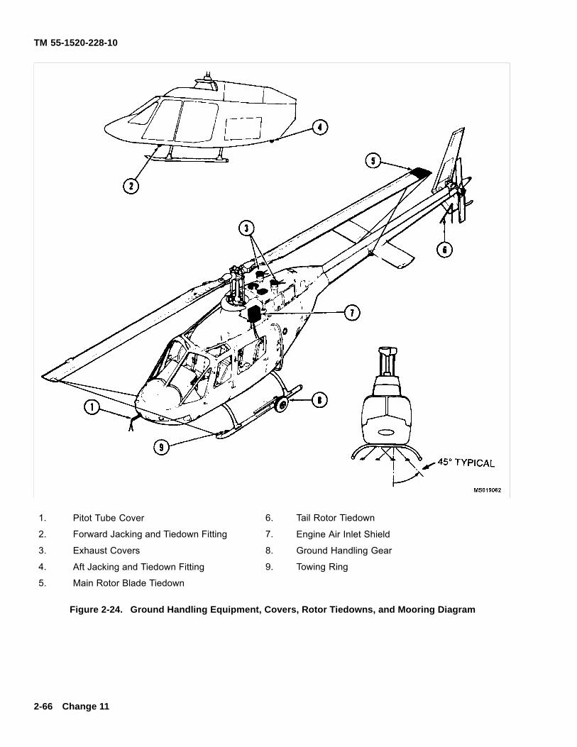
TM 55-1520-228-10
1. Pitot Tube Cover 6. Tail Rotor Tiedown
2. Forward Jacking and Tiedown Fitting 7. Engine Air Inlet Shield
3. Exhaust Covers 8. Ground Handling Gear
4. Aft Jacking and Tiedown Fitting 9. Towing Ring
5. Main Rotor Blade Tiedown
Figure 2-24. Ground Handling Equipment, Covers, Rotor Tiedowns, and Mooring Diagram
2-66 Change 11
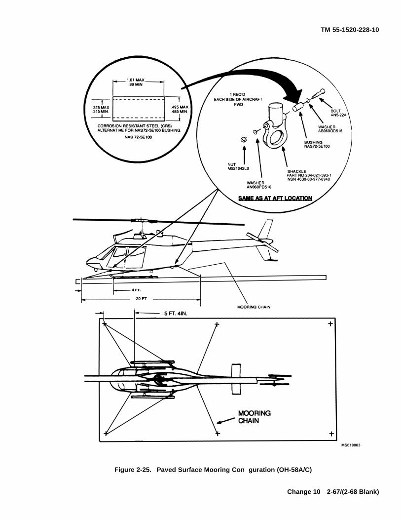
TM 55-1520-228-10
Figure 2-25. Paved Surface Mooring Con guration (OH-58A/C)
Change 10 2-67/(2-68 Blank)

TM 55-1520-228-10
CHAPTER 3AVIONICS
3-1. GENERAL. This chapter contains all informationrelevant to the avionics equipment installed in the ArmyModel OH-58A/C helicopter. Included information con-sists of description, technical characteristics, capability,location of each major component and operation instruc-tions for the system.
3-2. DELETED.
3-3. NOMENCLATURE AND COMMONNAMES. Avionics equipment installed in the he-
licopter, with common names, use, and operationalrange, is presented in Table 3-1. Antenna locations areshown in f gure 3-1.
3-4. DELETED.
3-5. POWER SUPPLY.
Refer to f gure 2-18.
Table 3-1. Communications and Associated Electronics Equipment
NOMENCLATURE COMMON NAME USE RANGE
Communication SystemControl C-6533/ARC
Communication Control Interphone for pilotand crew, Integratesall communicationequipment
Stations within helicopter.
Radio SetAN/ARC114FM
FM Radio Set Two-way VoiceCommunications infrequency range of 30.00to 75.95 MHz
Line of sight
Radio Set AN/ARC114AVHF-FM
FM Radio Two-way VoiceCommunications infrequency range of 30.00to 75.95 MHz
Line of sight
Radio SetAN/ARC115VHF-AM
VHF Radio Set Two-way VoiceCommunications infrequency range of 116.00to 149.975 MHz
Line of sight
Radio SetAN/ARC116UHF-AM(or AN/ARC-164)
UHF Radio Set Two-way VoiceCommunications in thefrequency range of 225.00to 399.95 MHz
Line of sight
Directional Finder/SetAN/ARN-89
ADF Radio Range Navigationand position f xingAutomatic directionf nding and homing inthe frequency range of100 to 3.000 KHz
150 to 200 miles averagedepending on terraininterference noise.
Change 11 3-1
TM 55-1520-228-10
Table 3-1. Communications and Associated Electronics Equipment — Continued
NOMENCLATURE COMMON NAME USE RANGE
Communication SecuritySet TSEC/KY-58
Secure-Voiceencoder-decoder
In conjunction with FMradio set to providesecure two-way voicecommunication
Gyromagnetic CompassSet AN/ASN-43
Gryomagnetic Compass Navigational Aid providesaccurate headinginformation
Transponder SetAN/APX-72
Transponder Set Transmit a special codedreply to ground based IFFradar interrogator system
Radio Set AN/ARN-123(V)1C.
Conus NavigationReceiver
With appropriateinstrumentation provides:VHF omni-directionalrange (VOR), localizer(LOC), glideslope (GS),and marker beacon (MB)position information
Line of sight
Radar AltimeterAN/APN-209
Radar Altimeter Provides altitudeindication above terrain.Permits selected altitudelimits and visual warningwhen altitude is above orbelow selected limits
0 to 1500 feet above terrain.
Transponder SetAN/APX-100C.
IFF Transponder Radio Transmits a special codedreply for radar interrogatorsystems
Line of sight
3-2 Change 11
TM 55-1520-228-10
Table 3-1. Communications and Associated Electronics Equipment — Continued
NOMENCLATURE COMMON NAME USE RANGE
Indicator, Heading-Radio BearingID-1351C/A
RHBI Provides magneticheading, VOR or ADFbearing, and hominginformation.
Indicator, CourseDeviationID-1347C/ARN
CDI Provides VOR coursedeviation, localizerand glideslope signalinformation.
Command Radio SetControl C-6287
Control/IndicatorC-6287
Secure-Voice ControlIndicator
Control/IndicatorC-8157/ARC
Computer Kit 1A/TSEC IFF Computer
Radar WarningAN/APR-39
Radar Warning Set Visual and AudibleWarning when a highradar threat environmentis encountered.
Line of sight
SINCGARS Radio SetAN/ARC-201
FM Radio Set Two-way VoiceCommunications infrequency range of 30to 87.975 MHz
Line of sight
IFM Amplif er AN-7189/A FM RF Amplif er Improves FMcommunication duringNOE f ight envelopes.
Line of sight
Change 14 3-3
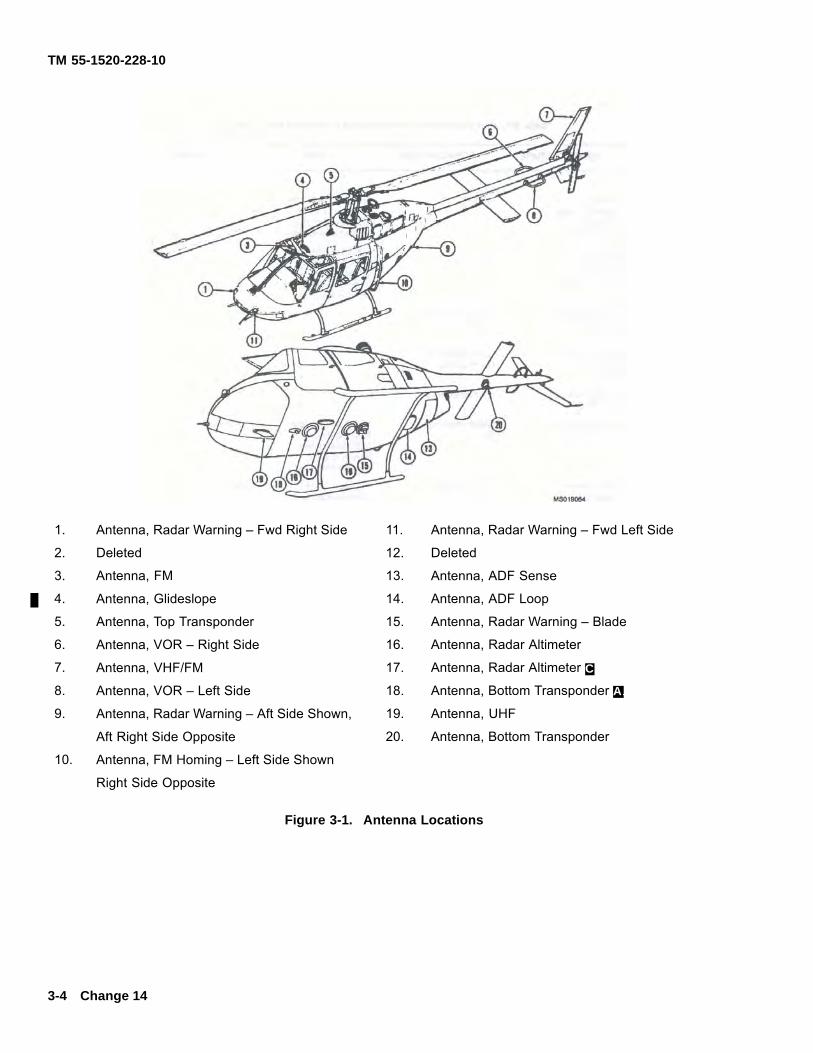
TM 55-1520-228-10
1. Antenna, Radar Warning – Fwd Right Side 11. Antenna, Radar Warning – Fwd Left Side
2. Deleted 12. Deleted
3. Antenna, FM 13. Antenna, ADF Sense
4. Antenna, Glideslope 14. Antenna, ADF Loop
5. Antenna, Top Transponder 15. Antenna, Radar Warning – Blade
6. Antenna, VOR – Right Side 16. Antenna, Radar Altimeter
7. Antenna, VHF/FM 17. Antenna, Radar Altimeter C.
8. Antenna, VOR – Left Side 18. Antenna, Bottom Transponder A.
9. Antenna, Radar Warning – Aft Side Shown, 19. Antenna, UHF
Aft Right Side Opposite 20. Antenna, Bottom Transponder
10. Antenna, FM Homing – Left Side Shown
Right Side Opposite
Figure 3-1. Antenna Locations
3-4 Change 14
TM 55-1520-228-10
SECTION I COMMUNICATIONS
3-6. COMMUNICATIONS SYSTEM CONTROL,C-6533/ARC.
3-7. DESCRIPTION — COMMUNICATIONSSYSTEM CONTROL.
The communication system control, C-6533/ARC (f g-ure 3-2) provides an intercommunications capability andcontrol of radio communications. Two of the control pan-els are installed on the instrument panel, one each forthe pilot and another crew member. Another controlpanel is installed on the right side overhead in the pas-senger compartment. The control panels may be usedin any one of three different modes as determined by thesetting of switches and controls on the panel.
3-8. CONTROLS AND FUNCTIONS —COMMUNICATION SYSTEM CONTROL.
Refer to f gure 3-2.
3-9. OPERATING PROCEDURES —COMMUNICATIONS SYSTEM CONTROL.
a. Modes of Operation. The three modes of oper-ation are two-way radio communication, radio receivermonitoring, and intercommunications within the heli-copter.
b. Operation.(1) Receiver switches — As desired.
(2) VOLume control — Adjust.
(3) HOT MIKE switch — As desired.
(4) Transmit-Interphone Selector — As re-quired.
3-10. VHF/FM RADIO SET.
3-11. DESCRIPTION — VHF/FM RADIO SET.
The AN/ARC-114 and AN/ARC-114A radio sets providetwo way frequency modulated (FM) narrow band voicecommunications and homing capability (Number oneunit only) within frequency range of 30.00 to 75.95 MHzon 920 channels for a 50-mile distance as limited by lineof sight. A guard receiver incorporated in the set is f xedtuned to 40.50 MHz. Retransmission of voice, CW orX-mode communications is possible when a second setis installed in the helicopter. The radio sets are markedVHF/FM COMM and are installed in the center console.Antenna location is located as shown in f gure 3-1.
3-12. CONTROLS AND FUNCTIONS — FM RADIOSET.
Refer to f gure 3-3.
NOTE
When transmitting and/or receiving on VHF(FM) in secure mode, do not key or transmitsimultaneously on any other transmitter.
3-13. OPERATING PROCEDURES — FM RADIOSET.
a. Transmit/Receive(1) Function selector — As desired.
(2) Frequency — Select.
(3) RCVR TEST — Press to test.
(4) AUDIO — Adjust.
(5) Transmit.(a) Transmit-Interphone selector — Number
1 position (Number 5 position for second FM set).(b) RADIO transmit switch — Press.
b. Homing.
NOTE
FM homing capability is not provided for ATASequipped helicopters.
(1) Function selector — HOMING.
(2) AUDIO — Adjust.
(3) Observe homing indications on the radiobearing heading indicator.
c. Retransmission.
NOTE
Crew transmission may also be made while inRETRAN mode.
(1) Frequencies — Select (Both FM sets).
NOTE
Frequencies must have a minimum of f ve MHzdifference, such as 30.00 MHz and 35.00 MHz.
(2) Communications — Establish with each fa-cility by selecting number 1 position and then number 5position on the Transmit-Interphone selector.
Change 11 3-5
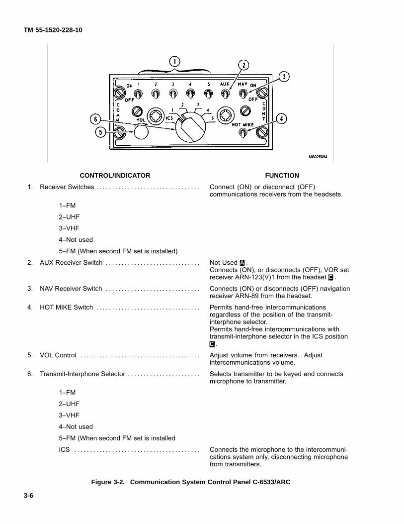
TM 55-1520-228-10
CONTROL/INDICATOR FUNCTION
1. Receiver Switches . . . . . . . . . . . . . . . . . . . . . . . . . . . . . . . . . Connect (ON) or disconnect (OFF)communications receivers from the headsets.
1–FM
2–UHF
3–VHF
4–Not used
5–FM (When second FM set is installed)
2. AUX Receiver Switch . . . . . . . . . . . . . . . . . . . . . . . . . . . . . . Not Used A..Connects (ON), or disconnects (OFF), VOR setreceiver ARN-123(V)1 from the headset C..
3. NAV Receiver Switch . . . . . . . . . . . . . . . . . . . . . . . . . . . . . . Connects (ON) or disconnects (OFF) navigationreceiver ARN-89 from the headset.
4. HOT MIKE Switch . . . . . . . . . . . . . . . . . . . . . . . . . . . . . . . . . Permits hand-free intercommunicationsregardless of the position of the transmit-interphone selector.Permits hand-free intercommunications withtransmit-interphone selector in the ICS positionC..
5. VOL Control . . . . . . . . . . . . . . . . . . . . . . . . . . . . . . . . . . . . . . Adjust volume from receivers. Adjustintercommunications volume.
6. Transmit-Interphone Selector . . . . . . . . . . . . . . . . . . . . . . . Selects transmitter to be keyed and connectsmicrophone to transmitter.
1–FM
2–UHF
3–VHF
4–Not used
5–FM (When second FM set is installed
ICS . . . . . . . . . . . . . . . . . . . . . . . . . . . . . . . . . . . . . . . . Connects the microphone to the intercommuni-cations system only, disconnecting microphonefrom transmitters.
Figure 3-2. Communication System Control Panel C-6533/ARC
3-6
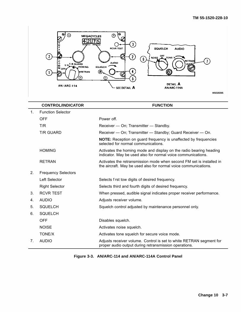
TM 55-1520-228-10
CONTROL/INDICATOR FUNCTION
1. Function Selector
OFF Power off.
T/R Receiver — On; Transmitter — Standby.
T/R GUARD Receiver — On; Transmitter — Standby; Guard Receiver — On.
NOTE: Reception on guard frequency is unaffected by frequenciesselected for normal communications.
HOMING Activates the homing mode and display on the radio bearing headingindicator. May be used also for normal voice communications.
RETRAN Activates the retransmission mode when second FM set is installed inthe aircraft. May be used also for normal voice communications.
2. Frequency Selectors
Left Selector Selects f rst tow digits of desired frequency.
Right Selector Selects third and fourth digits of desired frequency.
3. RCVR TEST When pressed, audible signal indicates proper receiver performance.
4. AUDIO Adjusts receiver volume.
5. SQUELCH Squelch control adjusted by maintenance personnel only.
6. SQUELCH
OFF Disables squelch.
NOISE Activates noise squelch.
TONE/X Activates tone squelch for secure voice mode.
7. AUDIO Adjusts receiver volume. Control is set to white RETRAN segment forproper audio output during retransmission operations.
Figure 3-3. AN/ARC-114 and AN/ARC-114A Control Panel
Change 10 3-7
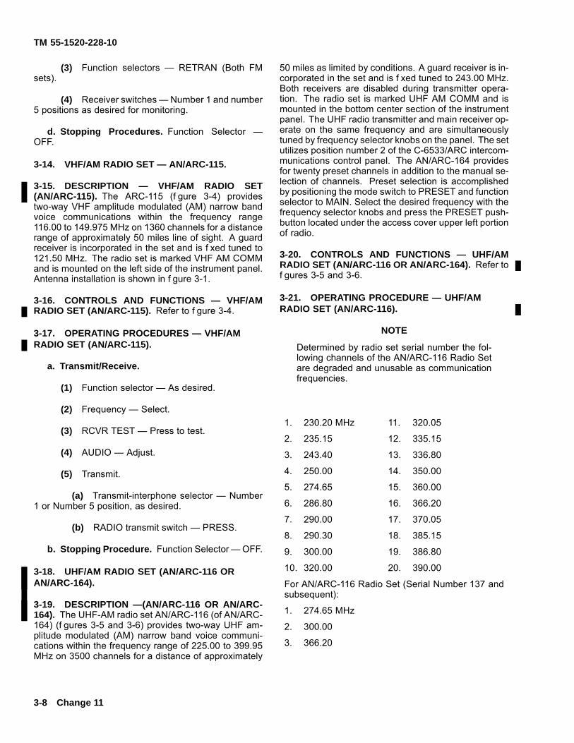
TM 55-1520-228-10
(3) Function selectors — RETRAN (Both FMsets).
(4) Receiver switches — Number 1 and number5 positions as desired for monitoring.
d. Stopping Procedures. Function Selector —OFF.
3-14. VHF/AM RADIO SET — AN/ARC-115.
3-15. DESCRIPTION — VHF/AM RADIO SET(AN/ARC-115). The ARC-115 (f gure 3-4) providestwo-way VHF amplitude modulated (AM) narrow bandvoice communications within the frequency range116.00 to 149.975 MHz on 1360 channels for a distancerange of approximately 50 miles line of sight. A guardreceiver is incorporated in the set and is f xed tuned to121.50 MHz. The radio set is marked VHF AM COMMand is mounted on the left side of the instrument panel.Antenna installation is shown in f gure 3-1.
3-16. CONTROLS AND FUNCTIONS — VHF/AMRADIO SET (AN/ARC-115). Refer to f gure 3-4.
3-17. OPERATING PROCEDURES — VHF/AMRADIO SET (AN/ARC-115).
a. Transmit/Receive.
(1) Function selector — As desired.
(2) Frequency — Select.
(3) RCVR TEST — Press to test.
(4) AUDIO — Adjust.
(5) Transmit.
(a) Transmit-interphone selector — Number1 or Number 5 position, as desired.
(b) RADIO transmit switch — PRESS.
b. Stopping Procedure. Function Selector — OFF.
3-18. UHF/AM RADIO SET (AN/ARC-116 ORAN/ARC-164).
3-19. DESCRIPTION —(AN/ARC-116 OR AN/ARC-164). The UHF-AM radio set AN/ARC-116 (of AN/ARC-164) (f gures 3-5 and 3-6) provides two-way UHF am-plitude modulated (AM) narrow band voice communi-cations within the frequency range of 225.00 to 399.95MHz on 3500 channels for a distance of approximately
50 miles as limited by conditions. A guard receiver is in-corporated in the set and is f xed tuned to 243.00 MHz.Both receivers are disabled during transmitter opera-tion. The radio set is marked UHF AM COMM and ismounted in the bottom center section of the instrumentpanel. The UHF radio transmitter and main receiver op-erate on the same frequency and are simultaneouslytuned by frequency selector knobs on the panel. The setutilizes position number 2 of the C-6533/ARC intercom-munications control panel. The AN/ARC-164 providesfor twenty preset channels in addition to the manual se-lection of channels. Preset selection is accomplishedby positioning the mode switch to PRESET and functionselector to MAIN. Select the desired frequency with thefrequency selector knobs and press the PRESET push-button located under the access cover upper left portionof radio.
3-20. CONTROLS AND FUNCTIONS — UHF/AMRADIO SET (AN/ARC-116 OR AN/ARC-164). Refer tof gures 3-5 and 3-6.
3-21. OPERATING PROCEDURE — UHF/AMRADIO SET (AN/ARC-116).
NOTE
Determined by radio set serial number the fol-lowing channels of the AN/ARC-116 Radio Setare degraded and unusable as communicationfrequencies.
1. 230.20 MHz 11. 320.05
2. 235.15 12. 335.15
3. 243.40 13. 336.80
4. 250.00 14. 350.00
5. 274.65 15. 360.00
6. 286.80 16. 366.20
7. 290.00 17. 370.05
8. 290.30 18. 385.15
9. 300.00 19. 386.80
10. 320.00 20. 390.00
For AN/ARC-116 Radio Set (Serial Number 137 andsubsequent):
1. 274.65 MHz
2. 300.00
3. 366.20
3-8 Change 11
TM 55-1520-228-10
a. Transmit/Receive.(1) Function selector – As desired.(2) Frequency– Select.(3) RCVR TEST– Press to test.(4) Audio – Adjust.(5) Transmit.
(a) Transmit – Interphone selector – Number2 position.
(b) RADIO transmit switch– PRESS.
b. Stopping Procedures. Function Selector - OFF.
3-22. OPERATING PROCEDURES – UHF/AMRADIO SET (AN/ARC-164).
a. Transmit/receive.(1) Function selector — As desired.(2) Frequency – Select.(3) TONE – Press to test.(4) VOL – Adjust.(5) Transmit.
(a) Transmit – Interphone selector – Number2 position.
(b) RADIO transmit switch – PRESS.
b. Stopping Procedure. Function Selector – OFF.
3-23. UHF/AM RADIO SET (RT-1167/ARC-164(V)OR RT-1167C/ARC-164(V)).
3-24. DESCRIPTION – UHF/AM RADIO SET(RT-1167/ARC-164(V) OR RT-1167C/ARC-164(V)).
a. RT-1167/ARC-164(V). The Receiver-TransmitterRadio RT-1167/ARC-164(V) (f gure 3-6) is an airborne,ultra-high frequency (UHF), amplitude-modulated (AM),radio transmitting-receiving (transceiver) set. It containsa multichannel, electronically-tunable transceiver and af xed-tuned guard receiver. The transceiver operates onany one of 7,000 channels spaced in 0.025 MHz unitsin the 225.000 to 399.750 MHz UHF military band. Theguard receiver is tunable in the 238.000 to 248.00 MHzfrequency range with crystal replacement and realign-ment (usually 243.000 MHz). The radio set primarily isused for voice communication. An additional radio setcapability, although not functional is ADF. Power to oper-ate the ARC-164(V) radio is from the 28 vdc emergencybus through a circuit breaker marked UHF-AM on thepilot overhead circuit breaker panel. UHF/AM Antennalocation is shown in f gure3-1.
b. RT-1167/ARC-164(V). The Receiver-Trans-mitter Radio RT-1167/ARC-164(V) (f gure 3-6)
has the same functions and capabilities as theRT-1167/ARC-164(V), plus a HAVE QUICK modeof operation. HAVE QUICK is an antijamming modewhich uses a frequency hopping scheme to changechannels many times per second. Because the HAVEQUICK mode depends on a precise time of day, bothHAVE QUICK radios must have synchronized clocks.UHF/AM Antenna location is shown in f gure3-1.
3-25. CONTROLS AND FUNCTIONS –UHF/AM RADIO SET (RT-1167/ARC-164(V) ORRT-1167C/ARC-164(V)).
a. RT-1167/ARC-164(V). Controls for theRT-1167/ARC-164(V) are on the front panel of the unit(f gure 3-6). The function of each control is as follows:
CONTROL FUNCTIONFrequency selectorswitch 1
Selects 100’s digit offrequency (either 2 or 3) inMHz
Frequency selectorswitch 2
Selects 10’s digit offrequency (0 through9) in MHz
Frequency selectorswitch 3
Selects units digit offrequency (0 through 9) inMHz
Frequency selectorswitch 4
Selects tenths digit offrequency (0 through 9) inMHz
Frequency selectorswitch 5
Selects hundredths digit offrequency (00, 25, 50, 75)in MHz
Preset channel selectorswitch
Selects one of 20 presetchannels
MANUAL-PRESET-GUARD selector
Selects method offrequency selection
MANUAL Any of 7,000 frequenciesis manually selected usingthe f ve frequency selectorswitches
PRESET A frequency is selectedusing the preset channelselector switch for selectingany one of 20 presetchannels as indicated onthe CHAN indicator
GUARD The main receiveand transmitter areautomatically tuned to theguard frequency. Blocksout any frequency set eithermanually or preset
SQUELCH ON-OFFswitch
Turns squelch of mainreceive on or off
Change 11 3-8.1
TM 55-1520-228-10
— Continued
VOL control Adjusts volumeTONE switch Enables transmission and
headset monitoring of a1,020–Hz tone on selectedfrequency for maintenancecheck only
Mode selector switch Selects operating mode:OFF Turns power offMAIN Enables the transceiverBOTH Enables transceiver and
guard receiverADF Not operational
b. RT-1167C/ARC-164(V). The controls and func-tions of the RT-1167C/ARC-164(V) are identical to theRT-1167/ARC-164(V) with the exception of the follow-ing:
CONTROL FUNCTIONFrequency selector switch1 (T-2- 3-A)
Selects 100’s digit offrequency (either 2 or 3)in MHz. The A positionselects the HAVEQUICK mode. The Tposition (spring-loaded)allows the radio toreceive a new time ofday
3-26. OPERATING PROCEDURE– UHF/AMRADIO SET (RT-1167/ARC-164(V) ORRT-1167C/ARC-164(V)).
a. Modes of Operation. Depending on the settingsof the operating controls, the radio set can be used forthese modes of operation:
(1) Control (Mode) Settings.
(a) MAN mode: two-way voice communica-tions
(b) BOTH Mode: utilizing the transceiverconstant monitoring of guard receiver without losing theuse of the transceiver.
(c) Transmission of 1,020 Hz TONE signal
(2) Transmit/Receive (MAIN) mode.
(a) Set OFF-MAIN-BOTH-ADF selectorswitch to MAIN.
(b) Set MANUAL-PRESET-GUARD selectorswitch to MANUAL for manual frequency selection or toPRESET for preset channel selection.
(c) To manually select a frequency, rotate thef ve MHz selector switches until desired frequency is dis-played in indicator window.
NOTE
Clockwise rotation of the MHz selector switchesincreases frequency.
(d) To select a preset channel, rotate presetchannel selector switch until desired channel is dis-played in preset CHAN indicator window.
NOTE
Clockwise rotation of preset channel selectorswitch will increase the desired channel num-ber (1 to 20).
(3) Transmit/Receive/Guard Monitor (BOTH)mode.
(a) Set OFF-MAIN-BOTH-ADF selectorswitch to BOTH.
NOTE
The BOTH position turns on the transceiver andthe guard receiver. The guard receiver will re-main turned to 243 MHz regardless of manualor preset frequencies selected.
(b) Select desired manual frequency or pre-set channel. Refer to steps 3-26.a.(2)(c) and (d).
NOTE
If reception on the selected frequency interfereswith guard reception, detune the set by select-ing an open frequency or place MANUAL-PRE-SET-GUARD selector switch to GUARD.
3-8.2 Change 11
TM 55-1520-228-10
(4) 1020 Hz TONE Signal Transmission (MAIN)mode.
(a) Set OFF-MAIN-BOTH-ADF selectorswitch to MAIN.
(b) Select a desired frequency for TONEtransmission. Refer to steps 3-26.a.(2)(c) and (d).
(c) Push the TONE switch to transmit the1020Hz signal.
NOTE
Tone-modulated signal may be used to checkout the radio set and isolate faulty microphonecircuitry.
(5) HAVE QUICK mode (RT-1167C/ARC-164(V) only).
The HAVE QUICK mode can be activated in oneof two ways:
(a) Set MANUAL-PRESET-GUARD switchto MANUAL and set frequency selector switch 1 to A.
(b) Set MANUAL-PRESET-GUARD switchto PRESET and set preset channel selector switch tochannel 20.
b. HAVE QUICK System Operation.(1) A 3–2–T Knob (HAVE QUICK System Only).
A - Selects AJ mode3 - Allows manual selection of frequencies.2 - Allows manual selection of frequencies1 - Momentary position which enables the radio to
accept a new TOD for up to 60 seconds afterselection. Also used in conjunction with theemergency startup of the TOD clock when TODis not available from an external source.(2) TONE Button (HAVE QUICK). Depressing
the TONE button in normal or AJ mode interrupts recep-tion and transmits a tone signal and TOD on the selectedfrequency. Simultaneously pressing the TONE button inconjunction with the A-3-2-T knob in the T position startsthe emergency startup of the TOD clock.
(3) HAVE QUICK System. The HAVE QUICK(HQ) system provides a jam resistant capability througha frequency hopping technique. Frequency hopping is atechnique in which the frequency being used for a givenchannel is automatically changed at some rate commonto the transmitter and receiver. The jam resistance of thesystem is due to the automatic frequency changing andthe pseudorandom pattern of frequencies used. In orderto defeat this communications system, the jammer mustf nd the frequency being used, jam it and then predict
or f nd the next frequency. The HAVE QUICK modif ca-tion adds the frequency hopping capability, yet it doesnot remove any of the previous capabilities of the radio.The HAVE QUICK modif ed radios retain the standard,single frequency UHF voice mode of operations. Thisis referred to as the normal mode, while frequency hop-ping operation is called the anti-jam (AJ) mode. Severalingredients are necessary for successful system opera-tions. These are:
1. Common frequency2. Time synchronization3. Common hopping pattern and rate4. Common net number
The common frequencies have been pro-grammed into all HAVE QUICK radios. Time syn-chronization is provided via UHF radio and/or hardwareby external time distribution system. A time-of-day(TOD) signal must be received from the time distribu-tion system for each time the radio is turned on. Thehopping pattern and hopping rate are determined bythe operator inserted word-of-day (WOD). The WODis a multi-digit code, common worldwide to all HAVEQUICK users. In the AJ mode, a communicationschannel is def ned by a net number instead of a signalfrequency as in the normal mode. Before operating inthe AJ mode, the radio must be primed. This consistsof setting the WOD, TOD, and the net number. The AJmode is then selected by placing the A-3-2-T knob to A.
(4) WORD OF DAY (WOD). The WOD entry isnormally entered before f ight, but it is possible to enterit in f ight. WOD is entered by using one or more of thesix preset channels which are 20-15. For a new WODentry, start at channel 20 use the same method as inentering preset frequencies in the normal mode with thefrequency knobs and the PRESET button. After eachentry, a single beep is heard until channel 15 entry; adouble beep is heard indicating that the radio has ac-cepted all six WOD entries.
(5) WOD TRANSFER. Select the preset modeand , starting with preset channel 20, rotate the presetknob CCW. At channel 20, a single beep is heard. A sin-gle beep indicates that channel 20 data has been trans-ferred and accepted. After the single beep is heard, se-lect remaining channels (19-15) in the same manner un-til a double beep is herad indicating the WOD transfer iscomplete.
(6) TIME-OF-DAY (TOD) transmission. TheTOD entry is normally entered before f ight, but it ispossible to enter it in f ight. It is possible to transmittiming information inboth normal and AJ modes bymomentarily pressing the TONE button. In the normal
Change 11 3-8.3

TM 55-1520-228-10
mode, a complete TOD message is transmitted, while inthe AJ mode, only an abbreviated time update is trans-mitted. A mode time transmission allows a time updateif one radio has drifted out of synchronization.
(7) TIME -OF-DAY Reception. Reception ispossible in both normal and AJ modes. The radioautomatically accepts the f rst TOD message after theradio is turned on and WOD transferred. Subsequentmessages are ignored unless the T position is selectedwith the A-3-2-T knob. The radio then accepts the nextTOD update in either normal or AJ mode, provided theTOD update arrives within 60 seconds of the time theT position has been selected. To receive time in thenormal mode, rotate the A-3-2-T knob to the T positionand return to a normal channel in either the manual or
preset mode. To receive a time update in AJ mode,rotate the A-3-2-T knob to the T position and then backto the A position. A TOD update (time tick) can bereceived on the selected AJ net.
(8) Net Numbers. After WOD and TOD are en-tered, any valid AJ net number can be selected by usingthe manual frequency knob.
(9) Anti-Jamming Mode Operation. A tone isheard in the headset if an invalid AJ net is selected, ifTOD was not initially received, or if WOD was not en-tered. If the function knob is set to both and the AJmode is selected, any transmission on the guard chan-nel takes precedence over the AJ mode.
3-8.4 Change 11
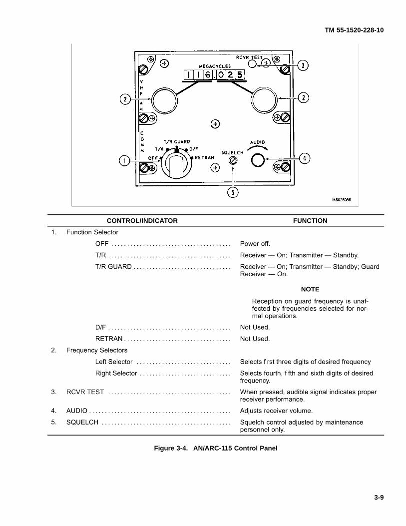
TM 55-1520-228-10
CONTROL/INDICATOR FUNCTION
1. Function Selector
OFF . . . . . . . . . . . . . . . . . . . . . . . . . . . . . . . . . . . . . . Power off.
T/R . . . . . . . . . . . . . . . . . . . . . . . . . . . . . . . . . . . . . . . Receiver — On; Transmitter — Standby.
T/R GUARD . . . . . . . . . . . . . . . . . . . . . . . . . . . . . . . Receiver — On; Transmitter — Standby; GuardReceiver — On.
NOTE
Reception on guard frequency is unaf-fected by frequencies selected for nor-mal operations.
D/F . . . . . . . . . . . . . . . . . . . . . . . . . . . . . . . . . . . . . . . Not Used.
RETRAN . . . . . . . . . . . . . . . . . . . . . . . . . . . . . . . . . . Not Used.
2. Frequency Selectors
Left Selector . . . . . . . . . . . . . . . . . . . . . . . . . . . . . . Selects f rst three digits of desired frequency
Right Selector . . . . . . . . . . . . . . . . . . . . . . . . . . . . . Selects fourth, f fth and sixth digits of desiredfrequency.
3. RCVR TEST . . . . . . . . . . . . . . . . . . . . . . . . . . . . . . . . . . . . . . . When pressed, audible signal indicates properreceiver performance.
4. AUDIO . . . . . . . . . . . . . . . . . . . . . . . . . . . . . . . . . . . . . . . . . . . . . Adjusts receiver volume.
5. SQUELCH . . . . . . . . . . . . . . . . . . . . . . . . . . . . . . . . . . . . . . . . . Squelch control adjusted by maintenancepersonnel only.
Figure 3-4. AN/ARC-115 Control Panel
3-9
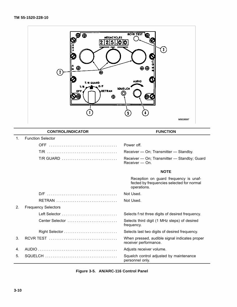
TM 55-1520-228-10
CONTROL/INDICATOR FUNCTION
1. Function Selector
OFF . . . . . . . . . . . . . . . . . . . . . . . . . . . . . . . . . . . . . Power off.
T/R . . . . . . . . . . . . . . . . . . . . . . . . . . . . . . . . . . . . . . Receiver — On; Transmitter — Standby.
T/R GUARD . . . . . . . . . . . . . . . . . . . . . . . . . . . . . . Receiver — On; Transmitter — Standby; GuardReceiver — On.
NOTE
Reception on guard frequency is unaf-fected by frequencies selected for normaloperations.
D/F . . . . . . . . . . . . . . . . . . . . . . . . . . . . . . . . . . . . . . Not Used.
RETRAN . . . . . . . . . . . . . . . . . . . . . . . . . . . . . . . . . Not Used.
2. Frequency Selectors
Left Selector . . . . . . . . . . . . . . . . . . . . . . . . . . . . . . Selects f rst three digits of desired frequency.
Center Selector . . . . . . . . . . . . . . . . . . . . . . . . . . . Selects third digit (1 MHz steps) of desiredfrequency.
Right Selector . . . . . . . . . . . . . . . . . . . . . . . . . . . . . Selects last two digits of desired frequency.
3. RCVR TEST . . . . . . . . . . . . . . . . . . . . . . . . . . . . . . . . . . . . . When pressed, audible signal indicates properreceiver performance.
4. AUDIO . . . . . . . . . . . . . . . . . . . . . . . . . . . . . . . . . . . . . . . . . . . Adjusts receiver volume.
5. SQUELCH . . . . . . . . . . . . . . . . . . . . . . . . . . . . . . . . . . . . . . . Squelch control adjusted by maintenancepersonnel only.
Figure 3-5. AN/ARC-116 Control Panel
3-10
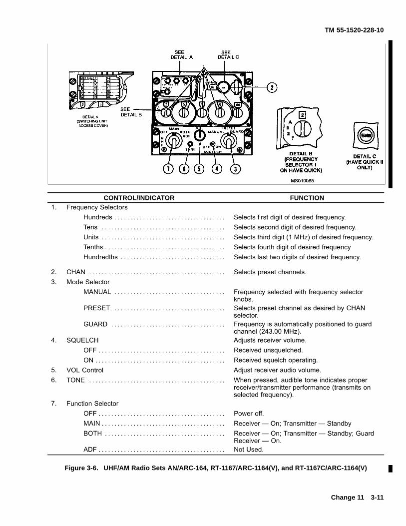
TM 55-1520-228-10
CONTROL/INDICATOR FUNCTION1. Frequency Selectors
Hundreds . . . . . . . . . . . . . . . . . . . . . . . . . . . . . . . . . . . Selects f rst digit of desired frequency.Tens . . . . . . . . . . . . . . . . . . . . . . . . . . . . . . . . . . . . . . . Selects second digit of desired frequency.Units . . . . . . . . . . . . . . . . . . . . . . . . . . . . . . . . . . . . . . . Selects third digit (1 MHz) of desired frequency.Tenths . . . . . . . . . . . . . . . . . . . . . . . . . . . . . . . . . . . . . . Selects fourth digit of desired frequencyHundredths . . . . . . . . . . . . . . . . . . . . . . . . . . . . . . . . . Selects last two digits of desired frequency.
2. CHAN . . . . . . . . . . . . . . . . . . . . . . . . . . . . . . . . . . . . . . . . . . . Selects preset channels.3. Mode Selector
MANUAL . . . . . . . . . . . . . . . . . . . . . . . . . . . . . . . . . . . Frequency selected with frequency selectorknobs.
PRESET . . . . . . . . . . . . . . . . . . . . . . . . . . . . . . . . . . . Selects preset channel as desired by CHANselector.
GUARD . . . . . . . . . . . . . . . . . . . . . . . . . . . . . . . . . . . . Frequency is automatically positioned to guardchannel (243.00 MHz).
4. SQUELCH Adjusts receiver volume.OFF . . . . . . . . . . . . . . . . . . . . . . . . . . . . . . . . . . . . . . . . Received unsquelched.ON . . . . . . . . . . . . . . . . . . . . . . . . . . . . . . . . . . . . . . . . . Received squelch operating.
5. VOL Control Adjust receiver audio volume.6. TONE . . . . . . . . . . . . . . . . . . . . . . . . . . . . . . . . . . . . . . . . . . . When pressed, audible tone indicates proper
receiver/transmitter performance (transmits onselected frequency).
7. Function SelectorOFF . . . . . . . . . . . . . . . . . . . . . . . . . . . . . . . . . . . . . . . . Power off.MAIN . . . . . . . . . . . . . . . . . . . . . . . . . . . . . . . . . . . . . . . Receiver — On; Transmitter — StandbyBOTH . . . . . . . . . . . . . . . . . . . . . . . . . . . . . . . . . . . . . . Receiver — On; Transmitter — Standby; Guard
Receiver — On.ADF . . . . . . . . . . . . . . . . . . . . . . . . . . . . . . . . . . . . . . . . Not Used.
Figure 3-6. UHF/AM Radio Sets AN/ARC-164, RT-1167/ARC-1164(V), and RT-1167C/ARC-1164(V)
Change 11 3-11
TM 55-1520-228-10
b. Radio Set ARC-164(V) Operation.
(1) TOD Transfer.
(a) Transfer WOD IAW paragraph 3-26.(5).
(b) Set up RT to receive TOD.1 With external TOD equipment.
a Select manual mode on MODEswitch.
b Set TOD frequency in manual fre-quency windows.
c Set A-3-2-T to A, after TOD beep isheard. If tone is heard with the A-3-2-T in the A position,reintialize radio IAW steps in paragraph 3-26.(6).
2 Without external TOD equipment:
Emergency start-up of TOD clock:a Set and hold A-3-2-T switch to T.b Press the TONE button.
NOTE
When using this method, the f ight commanderor lead aircraft should emergency-start his TODclock. Lead aircraft would then transfer TOD toother aircraft in f ight. Aircraft using this methodwill not be able to communicate with valid TODsignal in the AF mode. A valid TOD signal mustbe transferred to all aircraft that have invalidTOD time before effective AJ communicationscan be achieved.
(2) HAVE QUICK Checklist ARC-164. LoadingWord-of-Day (WOD)
(a) “T, 2, 3, A” switch — Not in A position.
(b) Functional selector switch — Both.
(c) Manual, preset, guard switch — Preset.
(d) Manual frequency display — Set WOD15.
(e) Preset channel select — Set to 15.
(f) Preset button (under frequency cover) —Press.
(g) Manual frequency display — Set WOD16.
(h) Preset channel select — Set to 16.(i) Preset button — Press.(j) Repeat steps g thru i to store WOD 17, 18,
19.(k) Manual frequency display — Set 300.050.(l) Preset channel select — Set to 20.(m) Preset button — Press.(n) Rotate preset select down 19, 18, 17, 16,
15, (hear 1 beep 20 — 16, 2 beeps on 15).
(3) Receiving Time from Net Control Aircraft.(a) Manual, preset, guard switch — Manual.(b) Set to internal frequency to receive the
time.(c) Hear net control aircraft state: “Standby
for time”.(d) Rotate “T, 2, 3, A” switch to “T” and return
to established manual frequency, hear.(e) Hear net control aircraft state: “Go active
0 point one”.(f) Set A00.100 in manual window and com-
plete commo check; if loud tone is heard, repeat timing.
(4) Sending Time (Net Control Aircraft).(a) Manual, preset, guard switch — Manual.(b) Set to internal frequency.(c) Rotate “T, 2, 3, A” switch to “T” on hold.(d) Press tone button and hold to (hear no
tone).(e) “T, 2, 3 A” to internal frequency (.25 sec-
ond beep, then tone)(f) Call other aircraft to send time.(g) Press tone button to send time.
NOTE
Recall today’s WOD by reselecting presets 20down thru 15, and hear beeps.
3-12 Change 11

TM 55-1520-228-10
Figure 3-7. HAS BEEN DELETED.
Change 11 3-13
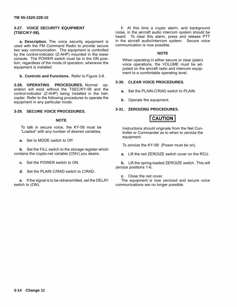
TM 55-1520-228-10
3-27. VOICE SECURITY EQUIPMENT(TSEC/KY-58).
a. Description. The voice security equipment isused with the FM Command Radio to provide securetwo way communication. The equipment is controlledby the control-indicator (Z-AHP) mounted in the lowerconsole. The POWER switch must be in the ON posi-tion, regardless of the mode of operation, whenever theequipment is installed.
b. Controls and Functions. Refer to Figure 3-8.
3-28. OPERATING PROCEDURES. Normal op-eration will exist without the TSEC/KY-58 and thecontrol-indicator (Z-AHP) being installed in the heli-copter. Refer to the following procedures to operate theequipment in any particular mode.
3-29. SECURE VOICE PROCEDURES.
NOTE
To talk in secure voice, the KY-58 must be“Loaded” with any number of desired variables.
a. Set to MODE switch to OP.
b. Set the FILL switch to the storage register whichcontains the crypto-net variable (CNV) you desire.
c. Set the POWER switch to ON.
d. Set the PLAIN C/RAD switch to C/RAD.
e. If the signal is to be retransmitted, set the DELAYswitch to (ON).
f. At this time a crypto alarm, and backgroundnoise, in the aircraft audio intercom system should beheard. To clear this alarm, press and release PTTin the aircraft audio/intercom system. Secure voicecommunication is now possible.
NOTE
When operating in either secure or clear (plain)voice operations, the VOLUME must be ad-justed on the aircraft radio and intercom equip-ment to a comfortable operating level.
3-30. CLEAR VOICE PROCEDURES.
a. Set the PLAIN-C/RAD switch to PLAIN.
b. Operate the equipment.
3-31. ZEROIZING PROCEDURES.
Instructions should originate from the Net Con-troller or Commander as to when to zeroize theequipment.
To zeroize the KY-58: (Power must be on).
a. Lift the red ZEROIZE switch cover on the RCU.
b. Lift the spring-loaded ZEROIZE switch. This willzeroize positions 1-6.
c. Close the red cover.The equipment is now zeroized and secure voice
communications are no longer possible.
3-14 Change 11
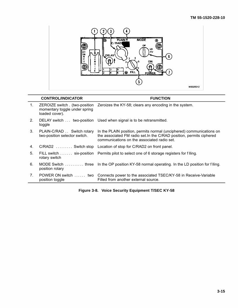
TM 55-1520-228-10
CONTROL/INDICATOR FUNCTION
1. ZEROIZE switch . (two-positionmomentary toggle under springloaded cover).
Zeroizes the KY-58; clears any encoding in the system.
2. DELAY switch . . . two-positiontoggle
Used when signal is to be retransmitted.
3. PLAIN-C/RAD . . Switch rotarytwo-position selector switch.
In the PLAIN position, permits normal (unciphered) communications onthe associated FM radio set.In the C/RAD position, permits cipheredcommunications on the associated radio set.
4. C/RAD2 . . . . . . . . . Switch stop Location of stop for C/RAD2 on front panel.
5. FILL switch . . . . . . . six-positionrotary switch
Permits pilot to select one of 6 storage registers for f lling.
6. MODE Switch . . . . . . . . . . threeposition rotary
In the OP position KY-58 normal operating. In the LD position for f lling.
7. POWER ON switch . . . . . . twoposition toggle
Connects power to the associated TSEC/KY-58 in Receive-VariableFilled from another external source.
Figure 3-8. Voice Security Equipment T/SEC KY-58
3-15
TM 55-1520-228-10
3-32. AUTOMATIC REMOTE KEYINGPROCEDURE.
NOTE
Automatic Remote Keying (AK) causes an “old”crypto-net variable (CNV) to be replaced by a“new” CNV. Net Controller simply transmit the“new” CNV to your KY-58.
a. The Net Controller will use a secure voice chan-nel, with directions to stand by a for an AK transmission.Calls should not be made during this stand by action.
b. Several beeps should now be heard in yourheadset. This means that the “old” CNV is being re-placed by a “new” CNV.
c. Using this “new” CNV, the net controller will askyou for a “radio check.”
d. After the “radio check” is completed, the NetController instructions will be to resume normal com-munications. No action should be taken until the netcontroller requests a “radio check.”
3-33. MANUAL REMOTE KEYING PROCE-DURES. The Net Controller will make contact on asecure voice channel with instructions to stand by fora new crypto-net variable (CNV) by a Manual RemoteKeying (MK) action. Upon instructions from the NetController:
a. Set the Z-AHP FILL switch to position 6. Notifythe Net Controller by radio, and stand by.
b. When notif ed by the Net Controller, set theZ-AHP MODE switch to RV (receive variable). Notifythe Net Controller, and stand by.
c. When notif ed by the Net Controller, set theZ-AHP FILL switch to any storage position selected toreceive the new CNV (may be unused or may containthe variable being replaced). Notify the Net Controller,and stand by.
NOTE
When performing Step c. the storage position(1 through 6) selected to receive the new CNVnay be unused, or it may contain the variablewhich is being replaced.
d. Upon instructions from the Net Controller:
(1) Listen for a beep on your headset.
(2) Wait two seconds.
(3) Set the RCU MODE switch to OP.
(4) Conf rm.
e. If the MK operation was successful, the Net Con-troller will now contact you via the new CNV.
f. If the MK operation was not successful, the NetController will contact you via clear voice (plain) trans-mission; with instructions to set your Z-AHP FILL selec-tor switch to position 6, and stand by while the MK op-eration is repeated.
3-34. KY-58 AUDIO TONES. It is important to be fa-miliar with certain KY-58 audio tones. Some tones indi-cate normal operation, while others indicate equipmentmalfunction. These tones are:
a. Continuous beeping, with background noise, iscryptoalarm. This occurs when power is f rst applied tothe KY-58, or when the KY-58 is zeroized. This beepingis part of normal KY-58 operation. To clear this tone,press and release the PTT button on the Z-AHQ (afterthe Z-AHQ LOCAL switch has been pressed). Also thePTT can be pressed in the cockpit.
b. Background noise indicates that the KY-58 isworking properly. This noise should occur at TURN ONof the KY-58, and also when the KY-58 is generating acryptovariable. If the background noise is not heard atTURN ON, the equipment must be checked out by main-tenance personnel.
c. Continuous tone, could indicate a “parity alarm.”This will occur whenever an empty storage register isselected while holding the PTT button is. This tone canmean any of three conditions:
(1) Selection of an empty storage register.
(2) A “bad” cryptovariable is present.
(3) Equipment failure has occurred. To clearthis tone, follow the “Loading Procedures” in TM11-5810-262-OP. If this tone continues, have the equip-ment checked out by maintenance personnel.
3-16
TM 55-1520-228-10
d. Continuous tone could also indicate a cryp-toalarm. If this tone occurs at any time other than in3-34.c above, equipment failure may have occurred.To clear this tone, repeat the “Loading Procedures” inTM 11-5810-262-OP. If this tone continues, have theequipment checked out by maintenance personnel.
e. Single beep, when RCU is not in TD (Time De-lay), can indicate any of three normal conditions:
(1) Each time the PTT button is pressed whenthe KY-58 is in C (cipher) and a f lled storage register isselected, this tone will be heard. Normal use (speaking)of the KY-58 is possible.
(2) When the KY-58 has successfully receiveda cryptovariable, this tone indicates that a “good” cryp-tovariable is present in the selected register.
(3) When you begin to receive a ciphered mes-sage, this tone indicates that the cryptovariable haspassed the “parity” check, and that it is a good variable.
f. A single beep, when the RCU is in TD (Time De-lay) occurring after the “preamble” is sent, indicates thatyou may being speaking.
g. A single beep, followed by a burst of noise afterwhich exists a seemingly “dead” condition indicates thatyour receiver is on a different variable than the distanttransmitter. If this tone occurs when in cipher text mode:Turn RCU FILL switch to the CNV and contact the trans-mitter in PLAIN text and agree to meet on a particularvariable.
SECTION II NAVIGATION
3-35. DIRECTION FINDER SET — (AN/ARN-89).
3-36. DESCRIPTION — DIRECTION FINDERSET(AN/ARN-89). The direction f nder set (ADF)AN/ARN-89 (f gure 3-9) is used in conjunction withgyromagnetic compass and intercommunications sys-tems. ADF bearing information is indicated on theheading-radio bearing indicator (f gure 3-10). the bear-ing pointer displays either the ADF bearing or the VORbearing depending on the position selected on the RMIBRG PNTR switch. The ADF set operates in the 100 to3000 KHz frequency range and is used to receive con-tinuous wave (cw) or amplitude modulated (am) radiofrequency signals. The three modes of operation for theADF set include automatic homing in the COMPASSmode, manual homing in the LOOP mode, and as acommunications receiver in the ANTenna mode. A beatfrequency oscillator is included to provide an audibleindication for identif cation and tuning and is activatedby the CW switch. The radio set control unit is markedADF RCVR and is mounted in the center section ofthe instrument panel. Antenna locations are shown inf gure 3-1.
3-37. CONTROLS AND FUNCTIONS — DIRECTIONFINDER SET (AN/ARN-89). Refer to f gure 3-9.
3-38. OPERATING PROCEDURES — DIRECTIONFINDER SET (AN/ARN-89).
a. COMPASS Mode.
(1) Function selector COMP.
(2) Frequency — Select. Tuning may be ac-complished with function selector in COMP, ANT, orLOOP positions; however, less noise is encountered inthe ANT position.
(3) AUDIO — Adjust.
(4) TUNE meter — Select. Tune for maximumup def ection of needle.
(5) CW VOICE TEST switch — TEST then re-lease.
(6) Observe ADF needle indications.
b. LOOP Mode.
(1) Function selector — LOOP.
(2) AUDIO — Adjust.
(3) CW VOICE TEST switch — CW.
(4) LOOP switch — Move left and right as re-quired to obtain aural null.
Change 11 3-17
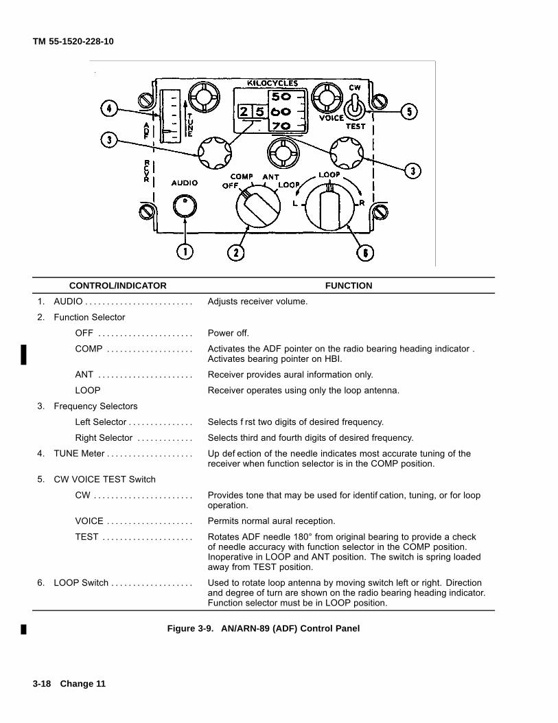
TM 55-1520-228-10
CONTROL/INDICATOR FUNCTION
1. AUDIO . . . . . . . . . . . . . . . . . . . . . . . . . Adjusts receiver volume.
2. Function Selector
OFF . . . . . . . . . . . . . . . . . . . . . . Power off.
COMP . . . . . . . . . . . . . . . . . . . . Activates the ADF pointer on the radio bearing heading indicator .Activates bearing pointer on HBI.
ANT . . . . . . . . . . . . . . . . . . . . . . Receiver provides aural information only.
LOOP Receiver operates using only the loop antenna.
3. Frequency Selectors
Left Selector . . . . . . . . . . . . . . . Selects f rst two digits of desired frequency.
Right Selector . . . . . . . . . . . . . Selects third and fourth digits of desired frequency.
4. TUNE Meter . . . . . . . . . . . . . . . . . . . . Up def ection of the needle indicates most accurate tuning of thereceiver when function selector is in the COMP position.
5. CW VOICE TEST Switch
CW . . . . . . . . . . . . . . . . . . . . . . . Provides tone that may be used for identif cation, tuning, or for loopoperation.
VOICE . . . . . . . . . . . . . . . . . . . . Permits normal aural reception.
TEST . . . . . . . . . . . . . . . . . . . . . Rotates ADF needle 180° from original bearing to provide a checkof needle accuracy with function selector in the COMP position.Inoperative in LOOP and ANT position. The switch is spring loadedaway from TEST position.
6. LOOP Switch . . . . . . . . . . . . . . . . . . . Used to rotate loop antenna by moving switch left or right. Directionand degree of turn are shown on the radio bearing heading indicator.Function selector must be in LOOP position.
Figure 3-9. AN/ARN-89 (ADF) Control Panel
3-18 Change 11
TM 55-1520-228-10
c. Preliminary.
(1) Interphone control panel receiving NAVswitch — ON.
(2) RMI BRG PTR switch — ADF.
(3) Function selector — COMP.
(4) Frequency — Select.
(5) AUDIO — Adjust.
(6) TUNE meter — tune for maximum up needledef ection.
d. Manual Operation.
(1) Function selector — LOOP.
(2) VOICE CW switch — CW.
(3) Rotate LOOP control for maximum receptionand retune.
(4) Rotate LOOP control to f nd audible null po-sition and adjust volume for a 5 to 8 degree null width.
(5) Check for ambiguity — The ADF bearingpointer will either read the magnetic bearing to thestation or be 180 degrees out.
e. Stopping Procedure. Function Selector — OFF.
3-39. GYRO MAGNETIC COMPASS SET —AN/ASN-43.
3-40. DESCRIPTION — GYRO MAGNETICCOMPASS SET.
The gyro magnetic compass set provides accurateheading information, referenced to a free directionalgyro heading when operated in the DIR gyro mode(free gyro), or slaved to the earth’s magnetic f eld whenoperated in the MAG mode (magnetically slaved). Itprovides heading information in the form of a synchrooutput to the radio bearing heading indicator (and bypresenting the magnetic heading as a reference signalto the VOR C.).
3-41. CONTROLS AND FUNCTIONS — GYROMAGNETIC COMPASS SET.
Refer to paragraph 3-42.
3-42. OPERATING PROCEDURES — GYROMAGNETIC COMPASS SET.
a. DIR GYRO/MAG switch — DIR GYRO for freegyro mode operation.
b. DIR GYRO/MAG switch — MAG for slavedmode operation.
3-43. RADIO BEARING HEADING INDICATOR —ID-1351A.
3-44. DESCRIPTION — RADIO BEARING HEADINGINDICATOR. The ID-1351/A A. (ID-1351C/A C.) indica-tor is mounted on the instrument panel and providesmagnetic heading information and radio bearings by dis-playing information from the gyromagnetic compass set,ADF, (VOR C. ) and FM radios. Additionally, it pro-vides visual indications of gyromagnetic compass fail-ure, compass synchronization and approach to a radiostation. The compass correction card for this instrumentwill be located in the front of the aircraft logbook.
Change 11 3-19
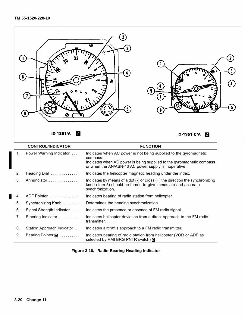
TM 55-1520-228-10
CONTROL/INDICATOR FUNCTION
1. Power Warning Indicator . . . . Indicates when AC power is not being supplied to the gyromagneticcompass.Indicates when AC power is being supplied to the gyromagnetic compassor when the AN/ASN-43 AC power supply is inoperative.
2. Heading Dial . . . . . . . . . . . . . . . Indicates the helicopter magnetic heading under the index.
3. Annunciator . . . . . . . . . . . . . . . . Indicates by means of a dot (•) or cross (+) the direction the synchronizingknob (item 5) should be turned to give immediate and accuratesynchronization.
4. ADF Pointer . . . . . . . . . . . . . . . Indicates bearing of radio station from helicopter .
5. Synchronizing Knob . . . . . . . . Determines the heading synchronization.
6. Signal Strength Indicator . . . . Indicates the presence or absence of FM radio signal.
7. Steering Indicator . . . . . . . . . . . Indicates helicopter deviation from a direct approach to the FM radiotransmitter.
8. Station Approach Indicator . . Indicates aircraft’s approach to a FM radio transmitter.
9. Bearing Pointer C. . . . . . . . . . . Indicates bearing of radio station from helicopter (VOR or ADF asselected by RMI BRG PNTR switch) C..
Figure 3-10. Radio Bearing Heading Indicator
3-20 Change 11
TM 55-1520-228-10
3-45. CONTROLS AND FUNCTIONS — RADIOBEARING HEADING INDICATOR. Refer to f gure3-10.
3-46. OPERATING PROCEDURES — RADIOBEARING HEADING INDICATOR.
a. Gyro-magnetic Heading Display andSynchronization.
(1) Gyro-magnetic heading dial rotates to indi-cate the helicopter’s magnetic heading under the index.
(2) Heading synchronization is accomplishedby rotating the synchronizing knob. The annunciator in-dicates, by means of a dot (•) or cross (+), the directionthat the synchronizing knob should be turned to giveimmediate and accurate synchronization. If a cross (+)is showing in the annunciator, the synchronizing knobshould be turned clockwise, and if a dot (•) is showing,the synchronizing knob should be turned counterclock-wise. The system is synchronized when the annunciatorindicates neither a dot (•) nor a cross (+). If, shortly aftersynchronizing the system, the heading dial drifts anda dot (•) or cross (+) appears in the annunciator, thenthe system was synchronized to a false null located180 degrees from the correct heading and should bere-synchronized to the correct helicopter heading. Thehelicopter standby magnetic compass may be checkedfor reference.
b. ADF Pointer A. (Bearing Pointer C.). Radiomagnetic bearing information is indicated by the ADFpointer of the indicator. The arrow end of this pointerindicates the bearing of the radio station from the heli-copter. The ADF set furnishes the bearing informationto the pointer (VOR or ADF as selected by the RMIBRG PTR switch located on the instrument panel C.).
c. FM Homing.
(1) The steering indicator receives its input fromthe number 1 FM radio homing system. By moving to theright or left of its center indication, the indicator showshelicopter deviation from a direct approach path to theFM radio transmitter. The indicator moves to the rightwhen the homing transmitter site is to the right of thehelicopter, and to the left when the transmitter is to theleft of the helicopter.
(2) An FM signal strength indicator shows redwhenever the FM radio receiver signal is absent or is tooweak for a reliable indication. When the signal strengthis acceptable, the FM signal strength indicator showsblack.
(3) The station approach indicator indicateshelicopter approach to the FM radio transmitter. Thepointer moves down as the transmitter is approached.
d. The power warning indicator comes into viewwhenever electrical AC power to the gyromagnetic com-pass is off, or inoperative.
3-47. C. CONUS NAVIGATION RECEIVER.
NOTE
Keying of the AN/ARC-115, VHF-AM transmit-ter may cause the AN/ARN-123 VOR receiver tolose station lock-on. The RMI BRG PTR on theheading radio bearing indicator and the coursepointer on the course deviation indicator will re-turn to center position and the VOR NAV warn-ing f ag will appear. The VOR receiver will re-turn to normal operation when the AN/ARC-115transmitter is unkeyed.
3-48. DESCRIPTION — CONUS NAVIGATION RE-CEIVER. The CONUS navigation receiver AN/ARN-123(V) receives the combined VOR (VHF omni-range)and LOC (localizer) signals over a frequency rangeof 108.000 to 117.95 MHz, GS (glideslope) signalsover a frequency range of 329.15 to 335.00 MHz,and MB (marker beacon) signals on 75.00 MHz fromground transmitters. The receiver is controlled by theC-10048/AR-123 control panel (f gure 3-11) mounted onthe lower right side of the instrument panel. The signalsare visually displayed on the CDI (f gure 3-12), and themarker beacon light as required. The VOR and local-izer audio signals are receiver from ground transmittersthrough the helicopter intercommunications system byplacing the interphone control (f gure 3-2) AUX switchto ON. The set enables the operator to determine hispresent position, direction to a given point, and f y apredetermined f ight path to localizer circuitry providesa visual display of the helicopter position relative to alocalizer course. The marker beacon circuitry providesa visual display and aural tone to indicate helicopterposition relative to a marker ground transmitter.
3-21
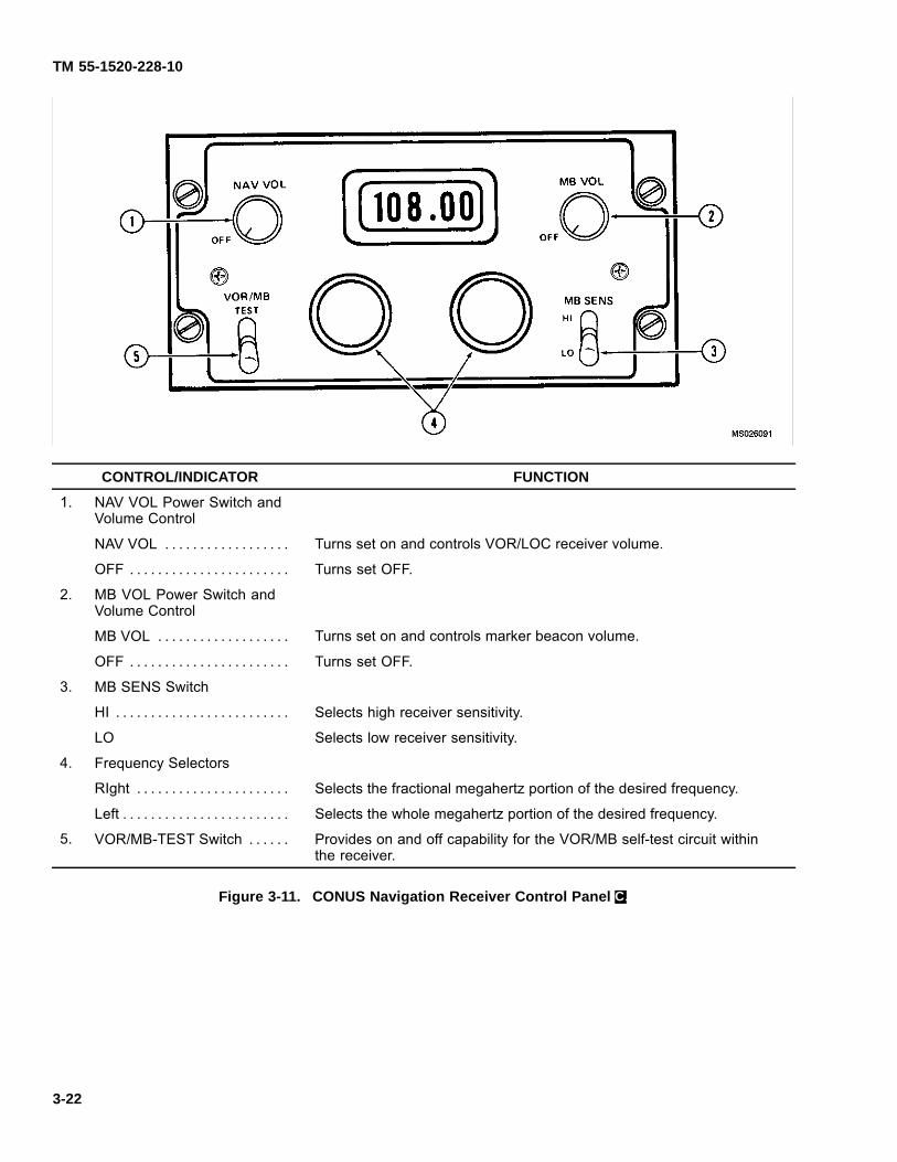
TM 55-1520-228-10
CONTROL/INDICATOR FUNCTION
1. NAV VOL Power Switch andVolume Control
NAV VOL . . . . . . . . . . . . . . . . . . Turns set on and controls VOR/LOC receiver volume.
OFF . . . . . . . . . . . . . . . . . . . . . . . Turns set OFF.
2. MB VOL Power Switch andVolume Control
MB VOL . . . . . . . . . . . . . . . . . . . Turns set on and controls marker beacon volume.
OFF . . . . . . . . . . . . . . . . . . . . . . . Turns set OFF.
3. MB SENS Switch
HI . . . . . . . . . . . . . . . . . . . . . . . . . Selects high receiver sensitivity.
LO Selects low receiver sensitivity.
4. Frequency Selectors
RIght . . . . . . . . . . . . . . . . . . . . . . Selects the fractional megahertz portion of the desired frequency.
Left . . . . . . . . . . . . . . . . . . . . . . . . Selects the whole megahertz portion of the desired frequency.
5. VOR/MB-TEST Switch . . . . . . Provides on and off capability for the VOR/MB self-test circuit withinthe receiver.
Figure 3-11. CONUS Navigation Receiver Control Panel C.
3-22
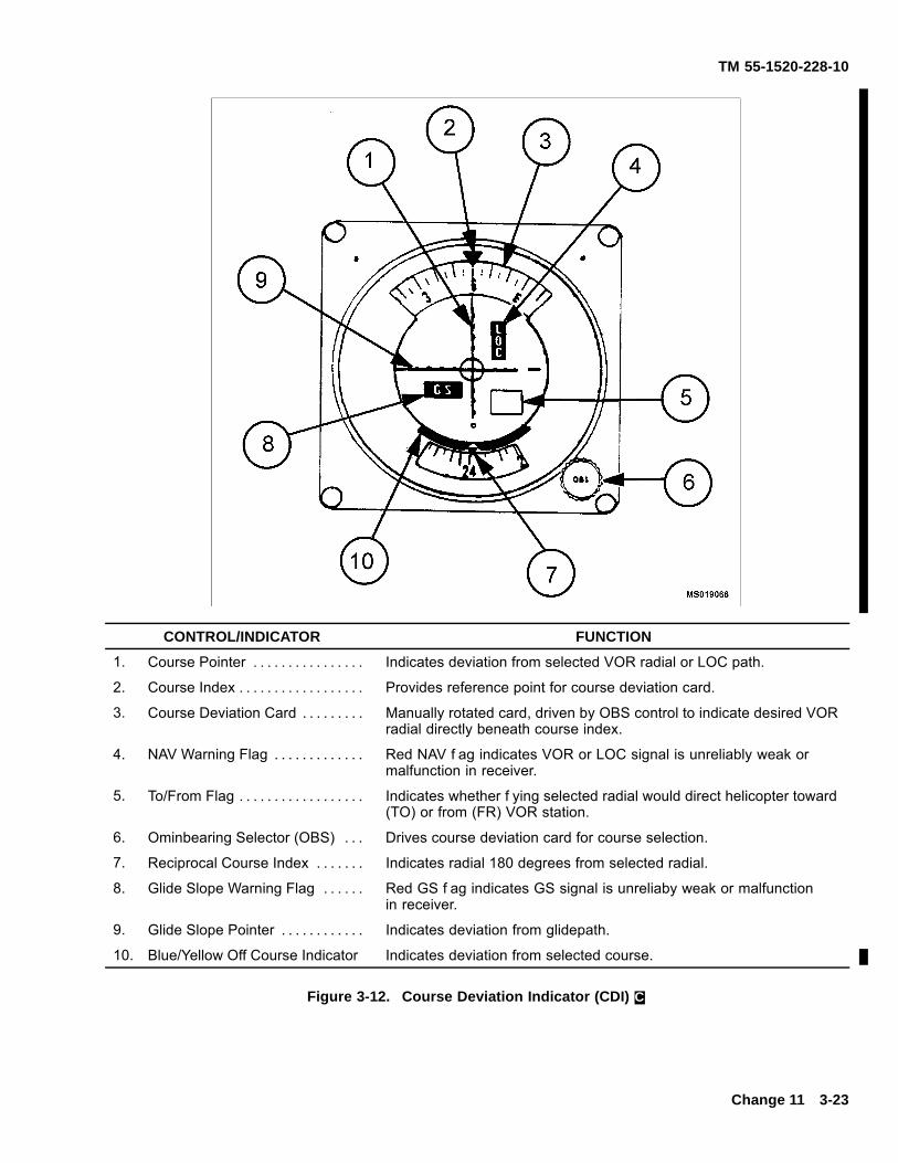
TM 55-1520-228-10
CONTROL/INDICATOR FUNCTION
1. Course Pointer . . . . . . . . . . . . . . . . Indicates deviation from selected VOR radial or LOC path.
2. Course Index . . . . . . . . . . . . . . . . . . Provides reference point for course deviation card.
3. Course Deviation Card . . . . . . . . . Manually rotated card, driven by OBS control to indicate desired VORradial directly beneath course index.
4. NAV Warning Flag . . . . . . . . . . . . . Red NAV f ag indicates VOR or LOC signal is unreliably weak ormalfunction in receiver.
5. To/From Flag . . . . . . . . . . . . . . . . . . Indicates whether f ying selected radial would direct helicopter toward(TO) or from (FR) VOR station.
6. Ominbearing Selector (OBS) . . . Drives course deviation card for course selection.
7. Reciprocal Course Index . . . . . . . Indicates radial 180 degrees from selected radial.
8. Glide Slope Warning Flag . . . . . . Red GS f ag indicates GS signal is unreliaby weak or malfunctionin receiver.
9. Glide Slope Pointer . . . . . . . . . . . . Indicates deviation from glidepath.
10. Blue/Yellow Off Course Indicator Indicates deviation from selected course.
Figure 3-12. Course Deviation Indicator (CDI) C.
Change 11 3-23
TM 55-1520-228-10
3-49. CONTROLS AND FUNCTIONS — CONUSNAVIGATION RECEIVER.
Refer to f gure 3-11.
3-50. OPERATING PROCEDURES — CONUSNAVIGATION RECEIVER.
a. System Operation.
(1) NAV VOL switch control – On and adjust.
(2) MB VOL switch control – On and adjust.
(3) VOR/MB/TEST switch – Press to test as fol-lows:
NOTE
This test requires an external VOR rf signal gen-erated by a ground station, or ramp test set.
(a) Set the course indicator OBS control for a315 degree indication under the course index.
(b) Move the control unit VOR/MB switch tothe TEST position (down).
(c) The CDI deviation needle should indicatecenter ±2 dots.
(d) The VOR/LOG f ag should be buried.
(e) The RMI should point to the 315 degreeradial (±5 degrees).
(f) The marker beacon lamp should illumi-nate.
(4) Frequency selectors – As required.
(5) MB SENS switch – As desired.
(6) RMI BRG PTA switch (located on instrumentpanel) – VOR.
(7) Interphone control panel AUX switch – ON.
(8) Interphone control panel VOL switch – Ad-just.
b. Stopping Procedure. NAV VOL AND MB VOLswitch controls – OFF.
3-51. COURSE DEVIATION INDICATOR (CDI).
3-52. DESCRIPTION – COURSE DEVIATIONINDICATOR.
THe CDI ID-1347C/ARN (f gure 3-12) is mounted onthe right side of the instrument panel and displays VOR,LOC, and GS bearing information received from theCONUS navigation receiver. Additionally, it providesvisual indications of unreliably weak VOR, LOC, andGS signals or equipment malfunction (NAV and GSf ags), to/from station indication, and course selection.
3-53. CONTROLS AND FUNCTIONS – COURSEDEVIATION INDICATOR.
Refer to f gure 3-12.
3-54. OPERATING PROCEDURES – COURSEDEVIATION INDICATOR.
Refer to f gure 3-12.
3-54.1. GLOBAL POSITIONING SYSTEM (MWO1-1520-228-50-53).
Operation of the Trimble Trimpack Global PositioningSystem (GPS) will be accomplished with the InterimStatement of Airworthiness Qualif cations (ISAQ) andappropriate commercial manuals.
3-24 Change 11
TM 55-1520-228-10
SECTION III TRANSPONDER AND RADAR
3-55. A. TRANSPONDER SET – AN/APX-72.
3-56. A. DESCRIPTION – TRANSPONDER SET.
The APX-72 (f gure 3-13) provides a radar identif cationcapability. Five independent coding modes are avail-able to the pilot. The f rst three modes may be usedindependently or in combination. Mode 1 provides 32possible code combinations, any one of which may beselected in f ight. Mode 2 provide 4,096 possible codecombinations but only one is available since the selec-tion dial is not available in f ight and must be preset be-fore f ight. Mode 3/A provide 4,096 possible codes, anyof which may be selected in f ight. Mode c is used withthe MU032/A Encoding altimeter. Mode 4, which is con-nected to an external computer, can be programmedprior to f ight to display any one of many classif ed op-erational codes for security identif cation. The effectiverange depends on the capability of interrogating radarand line-of-sight. The code setting can be mechani-cally retained. On the instrument Panel and Console– place the IFF CODE HOLD-OFF switch to the HOLDposition. On the Transponder Set Control Panel – turn
CODE switch to HOLD (only momentary action is re-quired). The transponder set is mounted on the upperleft side of the instrument panel. The associated an-tenna is shown in f gure 3-1.
3-57. A. CONTROLS AND FUNCTIONS –TRANSPONDER SET.
The control panel is located on the instrument panel. Itprovides remote control of the APX-72 transponder set.Mode 2 code select switch is on the front panel of thereceiver-transmitter radio. Controls and functions areshown in f gure 3-13.
3-58. A. OPERATING PROCEDURES –TRANSPONDER SET.
a. Transponder Operation.
(1) MASTER control – STBY. Allow approxi-mately 2 minutes for warmup.
Change 11 3-24.1/(3-24.2 Blank)

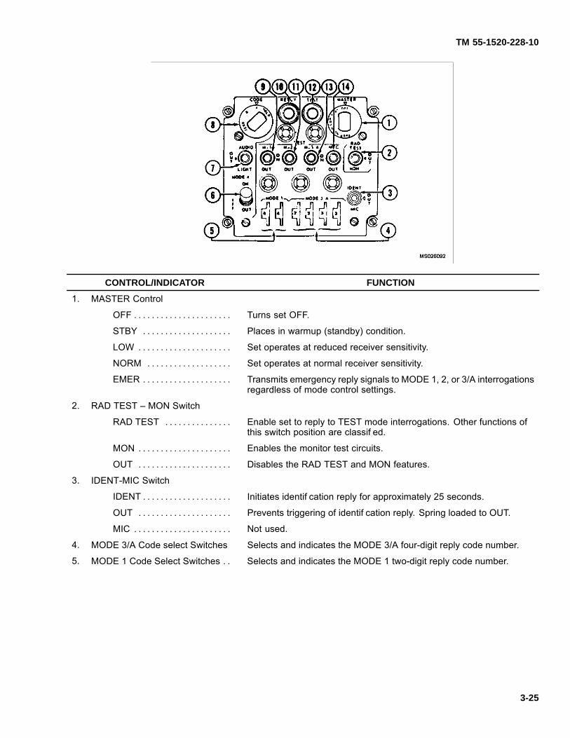
TM 55-1520-228-10
CONTROL/INDICATOR FUNCTION
1. MASTER Control
OFF . . . . . . . . . . . . . . . . . . . . . . Turns set OFF.
STBY . . . . . . . . . . . . . . . . . . . . Places in warmup (standby) condition.
LOW . . . . . . . . . . . . . . . . . . . . . Set operates at reduced receiver sensitivity.
NORM . . . . . . . . . . . . . . . . . . . Set operates at normal receiver sensitivity.
EMER . . . . . . . . . . . . . . . . . . . . Transmits emergency reply signals to MODE 1, 2, or 3/A interrogationsregardless of mode control settings.
2. RAD TEST – MON Switch
RAD TEST . . . . . . . . . . . . . . . Enable set to reply to TEST mode interrogations. Other functions ofthis switch position are classif ed.
MON . . . . . . . . . . . . . . . . . . . . . Enables the monitor test circuits.
OUT . . . . . . . . . . . . . . . . . . . . . Disables the RAD TEST and MON features.
3. IDENT-MIC Switch
IDENT . . . . . . . . . . . . . . . . . . . . Initiates identif cation reply for approximately 25 seconds.
OUT . . . . . . . . . . . . . . . . . . . . . Prevents triggering of identif cation reply. Spring loaded to OUT.
MIC . . . . . . . . . . . . . . . . . . . . . . Not used.
4. MODE 3/A Code select Switches Selects and indicates the MODE 3/A four-digit reply code number.
5. MODE 1 Code Select Switches . . Selects and indicates the MODE 1 two-digit reply code number.
3-25

TM 55-1520-228-10
CONTROL/INDICATOR FUNCTION
6. MODE 4 Switch
ON . . . . . . . . . . . . . . . . . . . . . . . Enables the set to reply to MODE 4 interrogations.
OUT . . . . . . . . . . . . . . . . . . . . . Disables the reply to MODE 4 interrogations.
7. AUDIO-LIGHT Switch
AUDIO . . . . . . . . . . . . . . . . . . . Enables aural and REPLY light monitoring of valid MODE 4interrogations and replies.
LIGHT . . . . . . . . . . . . . . . . . . . . Enables REPLY light only monitoring of valid MODE 4 interrogationsand replies.
OUT . . . . . . . . . . . . . . . . . . . . . Disables aural and REPLY light only monitoring of valid MODE 4interrogations and replies.
8. CODE Control . . . . . . . . . . . . . . . . . Holds, zeroizes or changes MODE 4 code.
9. M-1 Switch
ON . . . . . . . . . . . . . . . . . . . . . . . Enables the set to reply to MODE 1 interrogations.
OUT . . . . . . . . . . . . . . . . . . . . . Disables the reply to MODE 1 interrogations
TEST . . . . . . . . . . . . . . . . . . . . Provides test of MODE 1 interrogations by indication on TEST light.
10. REPLY Indicator . . . . . . . . . . . . . . . Lights when valid MODE 4 replies are present, or when pressed.
NOTE
Computer must be installed before set will reply to a MODe 4interrogation.
11. M-2 Switch
ON . . . . . . . . . . . . . . . . . . . . . . . Enables the set to reply to MODE 2 interrogations.
OUT . . . . . . . . . . . . . . . . . . . . . Disables the reply to MODE 2 interrogations.
TEST . . . . . . . . . . . . . . . . . . . . Provides test of MODE 2 interrogation by indication on TEST light.
12. Test indicator . . . . . . . . . . . . . . . . . . Lights when the set responds properly to a M-1, M-2, M-3/A or M-Ctest, or when pressed.
13. M-3/A Switch
ON . . . . . . . . . . . . . . . . . . . . . . . Enables the set to reply to MODE 3/A interrogations.
OUT . . . . . . . . . . . . . . . . . . . . . Disables the reply to MODE 3/A interrogations.
TEST . . . . . . . . . . . . . . . . . . . . Provides test of MODE 3/A interrogations by indication on TEST light.
14. M-C Switch
ON . . . . . . . . . . . . . . . . . . . . . . . Enables set to reply to MODE C interrogations.
OUT . . . . . . . . . . . . . . . . . . . . . Disables reply to MODE C interrogations.
TEST . . . . . . . . . . . . . . . . . . . . Enables TS-1843/APX to locally interrogate set.
Figure 3-13. Transponder APX-72 Control Panel A.
3-26
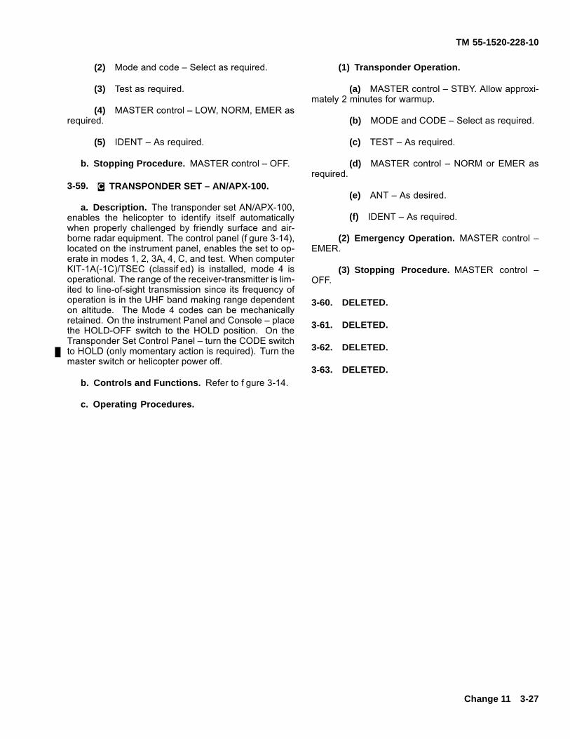
TM 55-1520-228-10
(2) Mode and code – Select as required.
(3) Test as required.
(4) MASTER control – LOW, NORM, EMER asrequired.
(5) IDENT – As required.
b. Stopping Procedure. MASTER control – OFF.
3-59. C. TRANSPONDER SET – AN/APX-100.
a. Description. The transponder set AN/APX-100,enables the helicopter to identify itself automaticallywhen properly challenged by friendly surface and air-borne radar equipment. The control panel (f gure 3-14),located on the instrument panel, enables the set to op-erate in modes 1, 2, 3A, 4, C, and test. When computerKIT-1A(-1C)/TSEC (classif ed) is installed, mode 4 isoperational. The range of the receiver-transmitter is lim-ited to line-of-sight transmission since its frequency ofoperation is in the UHF band making range dependenton altitude. The Mode 4 codes can be mechanicallyretained. On the instrument Panel and Console – placethe HOLD-OFF switch to the HOLD position. On theTransponder Set Control Panel – turn the CODE switchto HOLD (only momentary action is required). Turn themaster switch or helicopter power off.
b. Controls and Functions. Refer to f gure 3-14.
c. Operating Procedures.
(1) Transponder Operation.
(a) MASTER control – STBY. Allow approxi-mately 2 minutes for warmup.
(b) MODE and CODE – Select as required.
(c) TEST – As required.
(d) MASTER control – NORM or EMER asrequired.
(e) ANT – As desired.
(f) IDENT – As required.
(2) Emergency Operation. MASTER control –EMER.
(3) Stopping Procedure. MASTER control –OFF.
3-60. DELETED.
3-61. DELETED.
3-62. DELETED.
3-63. DELETED.
Change 11 3-27

TM 55-1520-228-10
CONTROL/INDICATOR FUNCTION1. TEST GO . . . . . . . . . . . . . . . . . . . . . . Indicates successful built in test (BIT).2. TEST/MON NO GO . . . . . . . . . . . . . Indicates unit malfunction.3. ANT
TOP . . . . . . . . . . . . . . . . . . . . . . Selects antenna located on top of helicopter.BOT . . . . . . . . . . . . . . . . . . . . . . Selects antenna located on bottom of helicopter.DIV . . . . . . . . . . . . . . . . . . . . . . . Selects both top and bottom antenna.
4. RAD TEST SwitchRAD TEST . . . . . . . . . . . . . . . . Enables set to reply to TEST mode interrogations.OUT . . . . . . . . . . . . . . . . . . . . . . Disables to RAD TEST features.
5. MASTER ControlOFF . . . . . . . . . . . . . . . . . . . . . . Turns set OFF.STBY . . . . . . . . . . . . . . . . . . . . . Places in warmup (standby) condition.NORM . . . . . . . . . . . . . . . . . . . . Set operates at normal receiver sensitivity.EMER . . . . . . . . . . . . . . . . . . . . . Transmits emergency reply signal to MODE 1, 2, or 3/A interrogations
regardless of mode control settings.
3-28
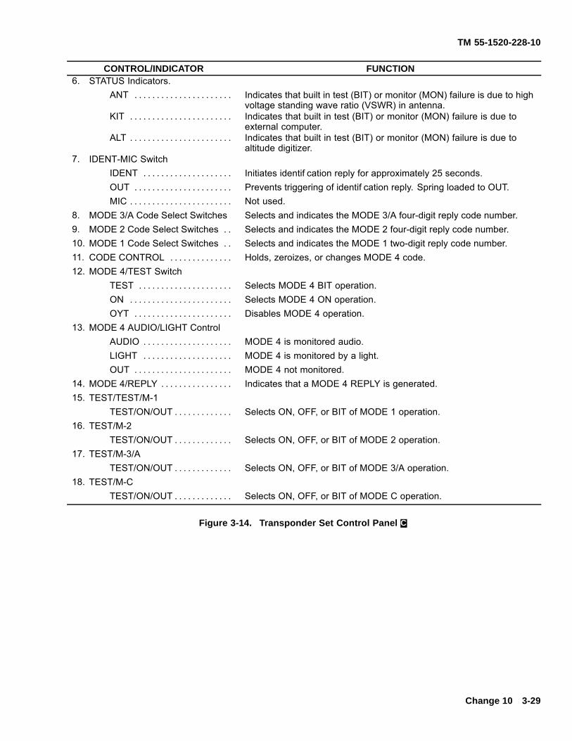
TM 55-1520-228-10
CONTROL/INDICATOR FUNCTION6. STATUS Indicators.
ANT . . . . . . . . . . . . . . . . . . . . . . Indicates that built in test (BIT) or monitor (MON) failure is due to highvoltage standing wave ratio (VSWR) in antenna.
KIT . . . . . . . . . . . . . . . . . . . . . . . Indicates that built in test (BIT) or monitor (MON) failure is due toexternal computer.
ALT . . . . . . . . . . . . . . . . . . . . . . . Indicates that built in test (BIT) or monitor (MON) failure is due toaltitude digitizer.
7. IDENT-MIC SwitchIDENT . . . . . . . . . . . . . . . . . . . . Initiates identif cation reply for approximately 25 seconds.OUT . . . . . . . . . . . . . . . . . . . . . . Prevents triggering of identif cation reply. Spring loaded to OUT.MIC . . . . . . . . . . . . . . . . . . . . . . . Not used.
8. MODE 3/A Code Select Switches Selects and indicates the MODE 3/A four-digit reply code number.9. MODE 2 Code Select Switches . . Selects and indicates the MODE 2 four-digit reply code number.10. MODE 1 Code Select Switches . . Selects and indicates the MODE 1 two-digit reply code number.11. CODE CONTROL . . . . . . . . . . . . . . Holds, zeroizes, or changes MODE 4 code.12. MODE 4/TEST Switch
TEST . . . . . . . . . . . . . . . . . . . . . Selects MODE 4 BIT operation.ON . . . . . . . . . . . . . . . . . . . . . . . Selects MODE 4 ON operation.OYT . . . . . . . . . . . . . . . . . . . . . . Disables MODE 4 operation.
13. MODE 4 AUDIO/LIGHT ControlAUDIO . . . . . . . . . . . . . . . . . . . . MODE 4 is monitored audio.LIGHT . . . . . . . . . . . . . . . . . . . . MODE 4 is monitored by a light.OUT . . . . . . . . . . . . . . . . . . . . . . MODE 4 not monitored.
14. MODE 4/REPLY . . . . . . . . . . . . . . . . Indicates that a MODE 4 REPLY is generated.15. TEST/TEST/M-1
TEST/ON/OUT . . . . . . . . . . . . . Selects ON, OFF, or BIT of MODE 1 operation.16. TEST/M-2
TEST/ON/OUT . . . . . . . . . . . . . Selects ON, OFF, or BIT of MODE 2 operation.17. TEST/M-3/A
TEST/ON/OUT . . . . . . . . . . . . . Selects ON, OFF, or BIT of MODE 3/A operation.18. TEST/M-C
TEST/ON/OUT . . . . . . . . . . . . . Selects ON, OFF, or BIT of MODE C operation.
Figure 3-14. Transponder Set Control Panel C.
Change 10 3-29

TM 55-1520-228-10
FIGURE 3-15. HAS BEEN DELETED.
3-30
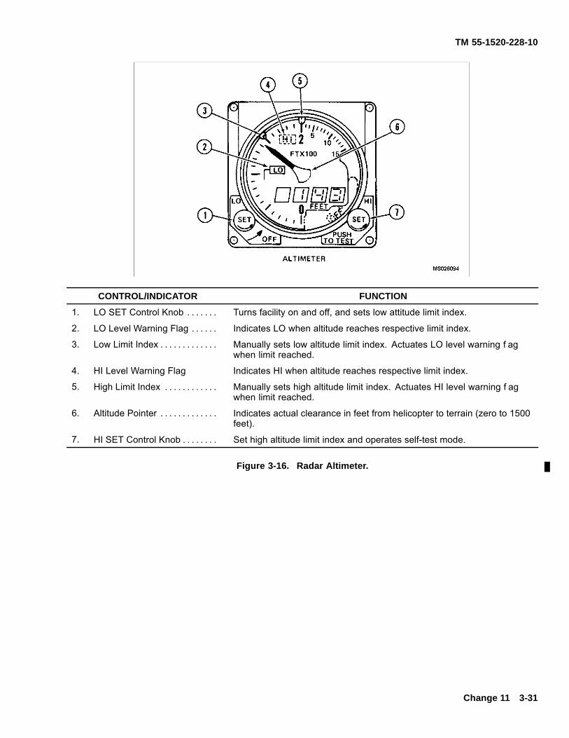
TM 55-1520-228-10
CONTROL/INDICATOR FUNCTION
1. LO SET Control Knob . . . . . . . Turns facility on and off, and sets low attitude limit index.
2. LO Level Warning Flag . . . . . . Indicates LO when altitude reaches respective limit index.
3. Low Limit Index . . . . . . . . . . . . . Manually sets low altitude limit index. Actuates LO level warning f agwhen limit reached.
4. HI Level Warning Flag Indicates HI when altitude reaches respective limit index.
5. High Limit Index . . . . . . . . . . . . Manually sets high altitude limit index. Actuates HI level warning f agwhen limit reached.
6. Altitude Pointer . . . . . . . . . . . . . Indicates actual clearance in feet from helicopter to terrain (zero to 1500feet).
7. HI SET Control Knob . . . . . . . . Set high altitude limit index and operates self-test mode.
Figure 3-16. Radar Altimeter.
Change 11 3-31
TM 55-1520-228-10
3-64. RADAR ALTIMETER (WITHOUT MWO1-1520-228-50-52).
NOTE
Simultaneous operation of the AN/APR-39,radar warning receiver and the AN/APN-209radar altimeter will cause a strobe to appear onthe AN/APR-39 CRT and an audio tone can beheard in the headset for IGE hover.
3-65. DESCRIPTION – RADAR ALTIMETER.
The radar altimeter AN/APN-209 (f gure 3-16) is a shortpulse, terrain tracking and altitude sensing radar sys-tem that measures and visually indicates by pointer anddigital display actual clearance in feet between the heli-copter and terrain over a range from zero to 1500 feet.The indicator contains all the electronic componentsnecessary for the generation, reception, and tracking ofthe radar pulses. The indicator provides precise altitudeindications with a manually set low-level and high-levelwarning f ag to warn when a predetermined low andhigh altitude limit has been reached.
3-66. CONTROLS AND FUNCTIONS – RADARALTIMETER.
Refer to f gure 3-16.
3-67. OPERATING PROCEDURES – RADARALTIMETER.
NOTE
Refer to TM 11-5841-284-23&P for additionaloperating instructions. Particular attention shallbe given to “Obstacle Avoidance” as follows:The altimeter system tracks the terrain belowthe aircraft and, therefore, will not provide use-ful information to aid in obstacle avoidance. Bythe time a suff cient area of an obstacle is withinthe antenna beams so the altimeter set can dis-play the near object, the aircraft probably couldnot be maneuvered to avoid the object.
a. Altimeter Operation.
(1) LO SET control knob – Rotate clockwisefrom OFF. Set low limit index as desired.
(2) HI SET control knob – Set high limit index asdesired.
b. Self-Test Operation.
(1) High limit index – Set to 800 feet.
(2) Low limit index – Set to 80 feet.
(3) HI SET control knob – Push and hold. Verifypointer indicates 1000 (± 100 feet), digital display reads1000 (± 100 feet), and HI level warning f ag is exposed.
(4) HI SET control knob – Release. Verifypointer indicates 0 (± 5) feet, digital display reads -0 to3 feet, and low warning f ag is exposed.
c. Stopping Procedure. LO SET control knob –Rotate counterclockwise from LO.
3-67.1. RADAR ALTIMETER (WITH MWO1-1520-228-50-52).
NOTE
Simultaneous operation of the AN/APR-39,radar warning receiver and the AN/APN-209radar altimeter will cause a strobe to appear onthe AN/APR-39 CRT and an audio tone can beheard in the headset for IGE hover.
3-67.2. DESCRIPTION – RADAR ALTIMETER.
The radar altimeter AN/APN-209 (V) (f gure 3-16) is ashort pulse, terrain tracking and altitude sensing radarsystem that measures and visually indicates by pointerand digital display actual clearance in feet betweenthe helicopter and terrain over a range from zero to1500 feet. The indicator contains all the electroniccomponents necessary for the generation, reception,and tracking of the radar pulses. The indicator providesprecise altitude indications with a manually set low-leveland high-level warning voice and f ag to warn whena predetermined low and high altitude limit has beenreached.
3-67.3. CONTROLS AND FUNCTIONS – RADARALTIMETER.
Refer to f gure 3-16.
3-32 Change 11
TM 55-1520-228-10
3-67.4. OPERATING PROCEDURES – RADARALTIMETER.
NOTE
Refer to TM 11-5841-284-23&P for additionaloperating instructions. Particular attention shallbe given to “Obstacle Avoidance” as follows:The altimeter system tracks the terrain belowthe aircraft and, therefore, will not provide use-ful information to aid in obstacle avoidance. Bythe time a suff cient area of an obstacle is withinthe antenna beams so the altimeter set can dis-play the near object, the aircraft probably couldnot be maneuvered to avoid the object.
a. Altimeter Operation.
(1) LO SET control knob – Rotate clockwisefrom OFF. Set low limit index as desired.
(2) HI SET control knob – Set high limit index asdesired.
b. Self Test Operation.
(1) Lower right knob – Press. The pointer anddigital display should read 1000 (± 100 feet). Also, theHI indicator on the radar altimeter should be illuminated.Release the knob. The reading should extinguish.
(2) Lower left knob – Adjust clockwise until theLO bug is positioned “above” (greater in altitude than)the pointer. A periodic audio warning “ALTITUDE LOW-TOO-LOW” should be heard in all headsets. Also, theLO indicator on the radar altimeter should be illuminated.
(3) Master ICS volume control – Rotate on eachrespective ICE unit. The audio warning volume shouldf uctuate. The audio warning volume level can also bealtered by momentarily pressing the Push-To-Talk (PTT)knob (lower-right) on the radar altimeter itself after thevoice warning has been initiated. Depress the PTT knobonce. The audio warning volume should be 1/2 the ini-tial level. Depress the PTT knob a second time, the au-dio warning message should be disabled. Once the vol-ume is reduced 1/2 initial level, the audio warning vol-ume level cannot be changed (except by adjusting themaster ICS volume control) or once disabled it cannotbe brought back.
(4) Lower left knob – Adjust counterclockwiseuntil the LO bug is “below” the pointer, then adjust theknob clockwise until the LO bug is positioned “above”the pointer again. The “ALTITUDE LOW – TOO LOW”audio warning should again be heard at its initial “FULL”volume level.
(5) Lower knob – Adjust counterclockwise untilthe LO bug is “below” the pointer, (but not quite to theOFF position). The warning audio should cease. TheLO indicator should be extinguished.
(6) Lower right knob – Depress and hold to putthe Radar Altimeter into the test mode. A periodic “AL-TIMETER HIGH-CHECK ALTITUDE” should be heardin all headsets. Also, the HI indicator on the radar al-timeter should be illuminated.
(7) Push-To-Test knob – Release. The warningaudio message should cease. The HI indicator shouldbe extinguished.
c. Stopping Procedure. LO SET control knob –Rotate counterclockwise from LO.
3-68. RADAR SIGNAL DETECTING SET(AN/APR-39A(V)1).
Refer toTM 11-5841-294-12.
3-68.1. DESCRIPTION – RADAR SIGNALDETECTING SET (AN/APR-39A(V)1).
a. Description. The radar signal detecting setAN/APR-39A(V)1 provides the pilot with visual andaudible warning when a hostile f re control threat isencountered. The equipment responds to hostilef re-control radars but non-threat radars are gener-ally excluded. The equipment also receives missileguidance radar signals and, when the signals aretime-coincident with a radar tracking signal, the equip-ment identif es the combination as an activated hostilesurface-to-air missile (SAM) radar system. The visualand aural displays warn the pilot of potential threat sothat evasive maneuvers can be initiated.
b. Function.
(1) The AN/APR-39A(V)1 receives, processesand displays pulse type signals operating in the C-D andH-M radio frequency bands. The emitters that it pro-cesses and displays are derived from the emitter iden-tif cation data (EID) contained in the user data module(UDM) that is inserted in the top of the digital processor.In normal circumstances the processor is classif ed con-f dential if a classif ed UDM is installed.
(2) The UDM contains the electronic warfarethreat data that makes up the specif c library for aspecif c mission(s) or a geographical location (it is the-aterized). When a match of the electronic warfare data
Change 11 3-32.1
TM 55-1520-228-10
occurs the processor generates the appropriate threatsymbology and synthetic audio. It is important thereforethat the correct theaterized EID and UDM are installedfor mission or geographic location.
(3) Symbol generation and position relative tothe center of the CRT shows the threat lethality, it doesnot show or represent and liability of range, but of con-dition/mode of the emitter. Highest priority threats (mostlethal) are shown nearest the center. Each symboldef nes a generic threat type, symbols are modif ed toshow change in the status of the emitter. The symbolsare unclassif ed, the def nitions of what the symbolsmean are classif ed. The complete set of symbols anddef nitions are contained in TM 11-5841-294-30-2. Eachtheaterized library EID has a specif c classif ed pilotkneeboard produced with it. The unit electronic warfareoff cer (EWO) should contact PM-ASE if suff cient cardsare not available within his unit for the installed EID.
3-69. CONTROLS AND FUNCTIONS – RADARSIGNAL DETECTING SET (AN/APR-39A(V)1).
Refer to f gure 3-17.
3-70. OPERATING PROCEDURES – RADARSIGNAL DETECTING SET (AN/APR-39A(V)1).
a. Self-Test Mode.
(1) After power up, the AN/APR-39A(V)1 syn-thetic voice will announce “APR-39 POWER UP” and the(+) symbol will stabilize in the center of the CRT. Self testshould be initiated after approximately one minute. Selftest can be performed in MODE ONE or MODE TWO.
In MODE ONE the synthetic voice will announce “SELFTEST SET VOLUME, 1, 2, 3, 4, 5, 6, 7, 8, 9, 10, 11, 12”.In MODE TWO the synthetic voice will announce “SELFTEST VOLUME, 5, 4, 3, 2, 1”.
(2) The CRT will display specif c software ver-sion numbers (i.e., operational f ight program (OFP) atthe 12 o’clock position and the emitter identif cation data(EID) at the 6 o’clock position.
(3) After the software version numbers havebeen displayed the test sequence checks the receivers.A good visual self test will show two triangles, one at the6 o’clock and one at the 12 o’clock position on the CRT.Snowf ake symbols (*) will appear at the 2, 4, 8, and10 o’clock positions and will f ash if the AN/AVR-2 laserdetecting set is not installed. this is a normal indicationand does not effect system performance.
(4) A good self test (no faults detected) endswith a message “APR-39 OPERATIONAL”. A bad selftest (faults detected) ends with the “APR-39 FAILURE”.
b. MODE 1 Operation. Selecting MODE ONEthe operator will hear all the normal synthetic voiceaudio when an emitter has been processed (e. g.,the AN/APR-39A(V)1 will announce; “SA, SA-18 12O’CLOCK TRACKING”). Selection of this mode doesnot have any effect on emitters received, processed ordisplayed. It only affects synthetic voice audio.
c. MODE 2 Operation. Selecting MODE TWO theoperator will hear abbreviated synthetic voice audio(e.g., the AN/APR-39A(V)1 will announce, “MISSILE 12O’CLOCK TRACKING”).
3-32.2 Change 11

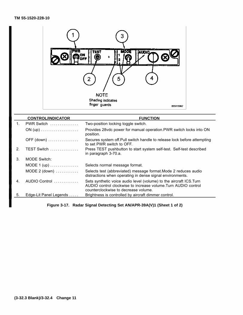
TM 55-1520-228-10
CONTROL/INDICATOR FUNCTION1. PWR Switch . . . . . . . . . . . . . . . Two-position locking toggle switch.
ON (up) . . . . . . . . . . . . . . . . . . . . Provides 28vdc power for manual operation.PWR switch locks into ONposition.
OFF (down) . . . . . . . . . . . . . . . . Secures system off.Pull switch handle to release lock before attemptingto set PWR switch to OFF.
2. TEST Switch . . . . . . . . . . . . . . . Press TEST pushbutton to start system self-test. Self-test describedin paragraph 3-70.a.
3. MODE Switch:MODE 1 (up) . . . . . . . . . . . . . . . Selects normal message format.MODE 2 (down) . . . . . . . . . . . . Selects test (abbreviated) message format.Mode 2 reduces audio
distractions when operating in dense signal environments.4. AUDIO Control . . . . . . . . . . . . . Sets synthetic voice audio level (volume) to the aircraft ICS.Turn
AUDIO control clockwise to increase volume.Turn AUDIO controlcounterclockwise to decrease volume.
5. Edge-Lit Panel Legends . . . . . Brightness is controlled by aircraft dimmer control.
Figure 3-17. Radar Signal Detecting Set AN/APR-39A(V)1 (Sheet 1 of 2)
(3-32.3 Blank)/3-32.4 Change 11
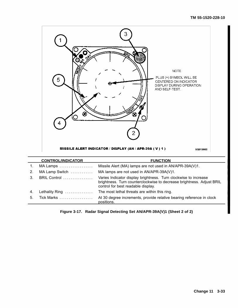
TM 55-1520-228-10
CONTROL/INDICATOR FUNCTION1. MA Lamps . . . . . . . . . . . . . . . . . . Missile Alert (MA) lamps are not used in AN/APR-39A(V)1.2. MA Lamp Switch . . . . . . . . . . . . MA lamps are not used in AN/APR-39A(V)1.3. BRIL Control . . . . . . . . . . . . . . . . Varies Indicator display brightness. Turn clockwise to increase
brightness. Turn counterclockwise to decrease brightness. Adjust BRILcontrol for best readable display.
4. Lethality Ring . . . . . . . . . . . . . . . The most lethal threats are within this ring.5. Tick Marks . . . . . . . . . . . . . . . . . . At 30 degree increments, provide relative bearing reference in clock
positions.
Figure 3-17. Radar Signal Detecting Set AN/APR-39A(V)1 (Sheet 2 of 2)
Change 11 3-33
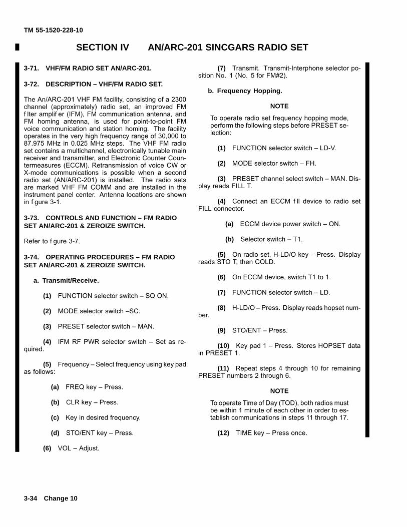
TM 55-1520-228-10
SECTION IV AN/ARC-201 SINCGARS RADIO SET
3-71. VHF/FM RADIO SET AN/ARC-201.
3-72. DESCRIPTION – VHF/FM RADIO SET.
The An/ARC-201 VHF FM facility, consisting of a 2300channel (approximately) radio set, an improved FMf lter amplif er (IFM), FM communication antenna, andFM homing antenna, is used for point-to-point FMvoice communication and station homing. The facilityoperates in the very high frequency range of 30,000 to87.975 MHz in 0.025 MHz steps. The VHF FM radioset contains a multichannel, electronically tunable mainreceiver and transmitter, and Electronic Counter Coun-termeasures (ECCM). Retransmission of voice CW orX-mode communications is possible when a secondradio set (AN/ARC-201) is installed. The radio setsare marked VHF FM COMM and are installed in theinstrument panel center. Antenna locations are shownin f gure 3-1.
3-73. CONTROLS AND FUNCTION – FM RADIOSET AN/ARC-201 & ZEROIZE SWITCH.
Refer to f gure 3-7.
3-74. OPERATING PROCEDURES – FM RADIOSET AN/ARC-201 & ZEROIZE SWITCH.
a. Transmit/Receive.
(1) FUNCTION selector switch – SQ ON.
(2) MODE selector switch –SC.
(3) PRESET selector switch – MAN.
(4) IFM RF PWR selector switch – Set as re-quired.
(5) Frequency – Select frequency using key padas follows:
(a) FREQ key – Press.
(b) CLR key – Press.
(c) Key in desired frequency.
(d) STO/ENT key – Press.
(6) VOL – Adjust.
(7) Transmit. Transmit-Interphone selector po-sition No. 1 (No. 5 for FM#2).
b. Frequency Hopping.
NOTE
To operate radio set frequency hopping mode,perform the following steps before PRESET se-lection:
(1) FUNCTION selector switch – LD-V.
(2) MODE selector switch – FH.
(3) PRESET channel select switch – MAN. Dis-play reads FILL T.
(4) Connect an ECCM f ll device to radio setFILL connector.
(a) ECCM device power switch – ON.
(b) Selector switch – T1.
(5) On radio set, H-LD/O key – Press. Displayreads STO T, then COLD.
(6) On ECCM device, switch T1 to 1.
(7) FUNCTION selector switch – LD.
(8) H-LD/O – Press. Display reads hopset num-ber.
(9) STO/ENT – Press.
(10) Key pad 1 – Press. Stores HOPSET datain PRESET 1.
(11) Repeat steps 4 through 10 for remainingPRESET numbers 2 through 6.
NOTE
To operate Time of Day (TOD), both radios mustbe within 1 minute of each other in order to es-tablish communications in steps 11 through 17.
(12) TIME key – Press once.
3-34 Change 10
TM 55-1520-228-10
(13) CLR key – Press.(a) Enter day.(b) ENT key – Press.(c) TIME key – Press.(d) CLR key – Press.(e) Enter hour(f) Enter minute(g) ENT key – Press.
(14) FUNCTION selector switch – SQ OFF.
(15) MODE selector switch FH.
(16) PRESET selector switch 1.
(17) Establish communications.
c. Homing.
(1) MODE selector switch – HOM.
(2) Frequency – Select FM Homing station fre-quency using key pad as follows:
(a) FREQ key – Press.(b) CLR key – Press.(c) Key in desired frequency.(d) STO/ENT key – Press.
(3) Observe homing information on the head-ing-radio bearing indicator.
d. Retransmission.
NOTE
Frequencies must have a minimum of 5 MHzdifference, such as 30.00 MHz and 35.00 MHz.
(1) Frequencies – Select (Both FM Sets)
(2) Communications – Establish with each facil-ity by selecting number 1 position and then number 5position on Transmit-Interphone selector.
(3) FUNCTION – selector switch – RXMT (BothFM Sets).
(4) FUNCTION – selector switch – OFF.
e. Scanning. The RT can scan up to eight presetSC frequencies. The frequencies it can scan are theones loaded into the presets 1–6, MAN, and CUE. Whena signal is found, that channel is locked in. The RT dis-
play will show the channel number, and you can listenand talk on that channel. When the channel has beeninactive for 2.5 seconds, scanning will begin again.
One of the presets can be selected to be the prioritypreset. The priority preset is scanned more often. TheRT will transmit on the priority preset at any time just bypressing the push-to-talk on the headset.
(1) Starting Scanning.(a) Set RT switches: FUNCTION – SQ ON;
MODE – FH; PRESET – CUE. Set other switches asneeded.
(b) Press STO (Sto/ENT) button on RT. Thedisplay reads: “SCAN.”
(c) Press a number, 0-8. This tells the RTwhich preset has priority (0 is MAN; 7 is CUE; 8 is nopriority).
(2) Transmitting on a Locked-in Preset. Presspush-to-talk and speak into headset. Do this within 2.5seconds after traff c has stopped.
(3) Selecting a Preset for Transmission. Pressnumber for channel on radio set keyboard. Press push-to-talk within 2.5 seconds after display shows presetnumber.
(4) Cancelling a Preset fro Scan Sequence.Press number for preset on radio set keyboard, thenpress CLR. The priority preset cannot be cancelled.The display changes to “CLR” and preset number.Scanning begins. The cancelled preset will not lock inagain.
(5) Restoring a Cancelled Preset. Press num-ber for the cancelled preset. The display will shows “CH”and preset number. The preset is now back in the scan-ning sequence.
(6) Starting Scanning While Locked on a Pre-set. Press STO (Sto/ENT) button on radio set.
(7) Checking Frequency of Locked-in Preset.Press FREQ push button on radio set while channelnumber is in display. The display changes to showfrequency.
(8) Stopping Scanning. Set radio set PRESETswitch to a different position.
3-75. ZEROIZE SWITCH.
a. Description. The zeroize switch provides theability to zeroize all special codes contained in theAN/ARC-201, TSEC/KY-58, and TSEC/KIT-1A Com-puter when activated. Power must be applied to aircraftin order for the switch to function.
Change 11 3-35
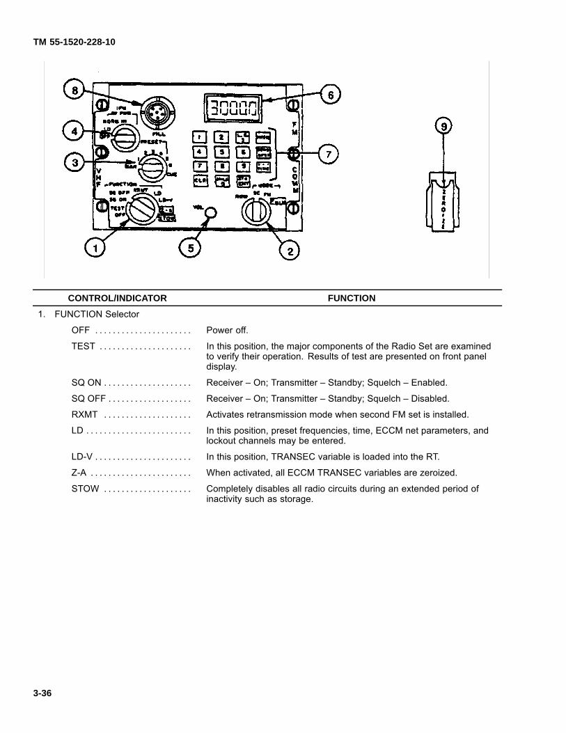
TM 55-1520-228-10
CONTROL/INDICATOR FUNCTION
1. FUNCTION Selector
OFF . . . . . . . . . . . . . . . . . . . . . . Power off.
TEST . . . . . . . . . . . . . . . . . . . . . In this position, the major components of the Radio Set are examinedto verify their operation. Results of test are presented on front paneldisplay.
SQ ON . . . . . . . . . . . . . . . . . . . . Receiver – On; Transmitter – Standby; Squelch – Enabled.
SQ OFF . . . . . . . . . . . . . . . . . . . Receiver – On; Transmitter – Standby; Squelch – Disabled.
RXMT . . . . . . . . . . . . . . . . . . . . Activates retransmission mode when second FM set is installed.
LD . . . . . . . . . . . . . . . . . . . . . . . . In this position, preset frequencies, time, ECCM net parameters, andlockout channels may be entered.
LD-V . . . . . . . . . . . . . . . . . . . . . . In this position, TRANSEC variable is loaded into the RT.
Z-A . . . . . . . . . . . . . . . . . . . . . . . When activated, all ECCM TRANSEC variables are zeroized.
STOW . . . . . . . . . . . . . . . . . . . . Completely disables all radio circuits during an extended period ofinactivity such as storage.
3-36
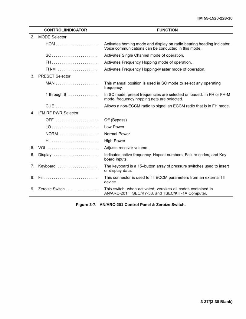
TM 55-1520-228-10
CONTROL/INDICATOR FUNCTION
2. MODE Selector
HOM . . . . . . . . . . . . . . . . . . . . . . Activates homing mode and display on radio bearing heading indicator.Voice communications can be conducted in this mode.
SC . . . . . . . . . . . . . . . . . . . . . . . . Activates Single Channel mode of operation.
FH . . . . . . . . . . . . . . . . . . . . . . . . Activates Frequency Hopping mode of operation.
FH-M . . . . . . . . . . . . . . . . . . . . . Activates Frequency Hopping-Master mode of operation.
3. PRESET Selector
MAN . . . . . . . . . . . . . . . . . . . . . . This manual position is used in SC mode to select any operatingfrequency.
1 through 6 . . . . . . . . . . . . . . . . In SC mode, preset frequencies are selected or loaded. In FH or FH-Mmode, frequency hopping nets are selected.
CUE . . . . . . . . . . . . . . . . . . . . . . Allows a non-ECCM radio to signal an ECCM radio that is in FH mode.
4. IFM RF PWR Selector
OFF . . . . . . . . . . . . . . . . . . . . . . Off (Bypass)
LO . . . . . . . . . . . . . . . . . . . . . . . . Low Power
NORM . . . . . . . . . . . . . . . . . . . . Normal Power
HI . . . . . . . . . . . . . . . . . . . . . . . . High Power
5. VOL . . . . . . . . . . . . . . . . . . . . . . . . . . Adjusts receiver volume.
6. Display . . . . . . . . . . . . . . . . . . . . . . . Indicates active frequency, Hopset numbers, Failure codes, and Keyboard inputs.
7. Keyboard . . . . . . . . . . . . . . . . . . . . . The keyboard is a 15–button array of pressure switches used to insertor display data.
8. Fill . . . . . . . . . . . . . . . . . . . . . . . . . . . . This connector is used to f ll ECCM parameters from an external f lldevice.
9. Zeroize Switch . . . . . . . . . . . . . . . . . This switch, when activated, zeroizes all codes contained inAN/ARC-201, TSEC/KY-58, and TSEC/KIT-1A Computer.
Figure 3-7. AN/ARC-201 Control Panel & Zeroize Switch.
3-37/(3-38 Blank)


TM 55-1520-228-10
CHAPTER 4MISSION EQUIPMENT
SECTION I MISSION AVIONICS
(NOT APPLICABLE)
SECTION II ARMAMENT
(NOT APPLICABLE) PAGES 4-2 THROUGH 4-20 (INCLUDING PARA-GRAPHS 4-1 THROUGH 4-29 AND FIGURES 4-1THROUGH 4-10) HAVE BEEN DELETED.
Change 10 4-1/(4-2 Blank)

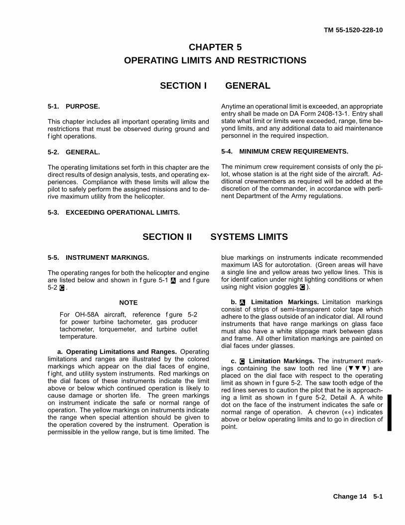
TM 55-1520-228-10
CHAPTER 5OPERATING LIMITS AND RESTRICTIONS
SECTION I GENERAL
5-1. PURPOSE.
This chapter includes all important operating limits andrestrictions that must be observed during ground andf ight operations.
5-2. GENERAL.
The operating limitations set forth in this chapter are thedirect results of design analysis, tests, and operating ex-periences. Compliance with these limits will allow thepilot to safely perform the assigned missions and to de-rive maximum utility from the helicopter.
5-3. EXCEEDING OPERATIONAL LIMITS.
Anytime an operational limit is exceeded, an appropriateentry shall be made on DA Form 2408-13-1. Entry shallstate what limit or limits were exceeded, range, time be-yond limits, and any additional data to aid maintenancepersonnel in the required inspection.
5-4. MINIMUM CREW REQUIREMENTS.
The minimum crew requirement consists of only the pi-lot, whose station is at the right side of the aircraft. Ad-ditional crewmembers as required will be added at thediscretion of the commander, in accordance with perti-nent Department of the Army regulations.
SECTION II SYSTEMS LIMITS
5-5. INSTRUMENT MARKINGS.
The operating ranges for both the helicopter and engineare listed below and shown in f gure 5-1 A. and f gure5-2 C..
NOTE
For OH-58A aircraft, reference f gure 5-2for power turbine tachometer, gas producertachometer, torquemeter, and turbine outlettemperature.
a. Operating Limitations and Ranges. Operatinglimitations and ranges are illustrated by the coloredmarkings which appear on the dial faces of engine,f ight, and utility system instruments. Red markings onthe dial faces of these instruments indicate the limitabove or below which continued operation is likely tocause damage or shorten life. The green markingson instrument indicate the safe or normal range ofoperation. The yellow markings on instruments indicatethe range when special attention should be given tothe operation covered by the instrument. Operation ispermissible in the yellow range, but is time limited. The
blue markings on instruments indicate recommendedmaximum IAS for autorotation. (Green areas will havea single line and yellow areas two yellow lines. This isfor identif cation under night lighting conditions or whenusing night vision goggles C.).
b. A. Limitation Markings. Limitation markingsconsist of strips of semi-transparent color tape whichadhere to the glass outside of an indicator dial. All roundinstruments that have range markings on glass facemust also have a white slippage mark between glassand frame. All other limitation markings are painted ondial faces under glasses.
c. C. Limitation Markings. The instrument mark-ings containing the saw tooth red line (▼▼▼) areplaced on the dial face with respect to the operatinglimit as shown in f gure 5-2. The saw tooth edge of thered lines serves to caution the pilot that he is approach-ing a limit as shown in f gure 5-2, Detail A. A whitedot on the face of the instrument indicates the safe ornormal range of operation. A chevron (««) indicatesabove or below operating limits and to go in direction ofpoint.
Change 14 5-1
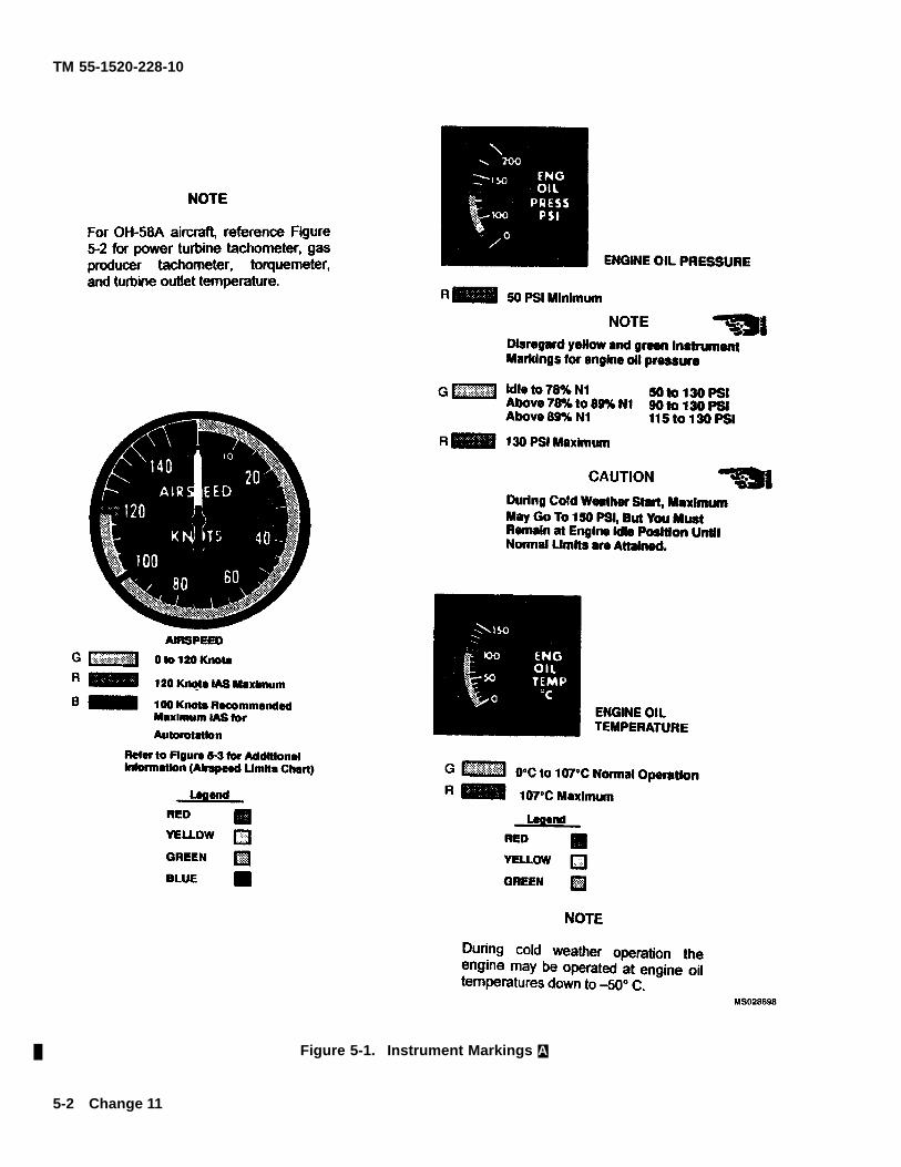
TM 55-1520-228-10
Figure 5-1. Instrument Markings A.
5-2 Change 11

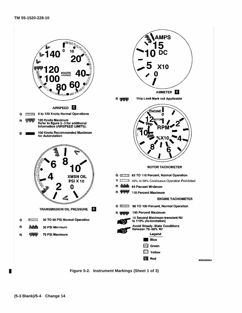
TM 55-1520-228-10
Figure 5-2. Instrument Markings (Sheet 1 of 3)
(5-3 Blank)/5-4 Change 14
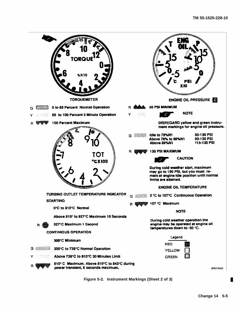
TM 55-1520-228-10
Figure 5-2. Instrument Markings (Sheet 2 of 3)
Change 14 5-5
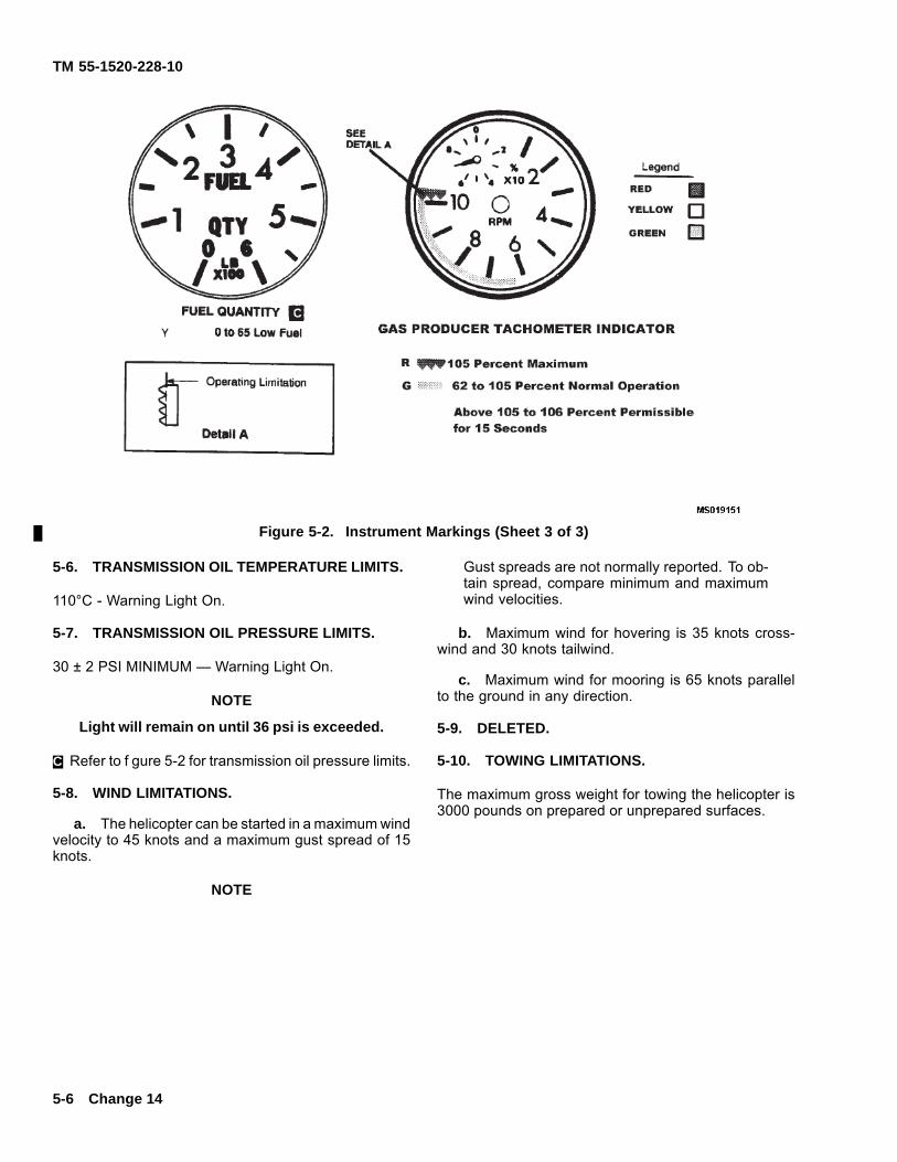
TM 55-1520-228-10
Figure 5-2. Instrument Markings (Sheet 3 of 3)
5-6. TRANSMISSION OIL TEMPERATURE LIMITS.
110°C - Warning Light On.
5-7. TRANSMISSION OIL PRESSURE LIMITS.
30 ± 2 PSI MINIMUM — Warning Light On.
NOTE
Light will remain on until 36 psi is exceeded.
C. Refer to f gure 5-2 for transmission oil pressure limits.
5-8. WIND LIMITATIONS.
a. The helicopter can be started in a maximum windvelocity to 45 knots and a maximum gust spread of 15knots.
NOTE
Gust spreads are not normally reported. To ob-tain spread, compare minimum and maximumwind velocities.
b. Maximum wind for hovering is 35 knots cross-wind and 30 knots tailwind.
c. Maximum wind for mooring is 65 knots parallelto the ground in any direction.
5-9. DELETED.
5-10. TOWING LIMITATIONS.
The maximum gross weight for towing the helicopter is3000 pounds on prepared or unprepared surfaces.
5-6 Change 14
TM 55-1520-228-10
SECTION III POWER LIMITS
5-11. ENGINE LIMITATIONS.
Refer to f gure 5-1A., f gure 5-2. If N2 limit is exceeded,entry on DA Form 2408-13-1 must include duration andtorque indicated.
5-12. FUEL OPERATION LIMITS.
a. JP-4. No restrictions are imposed when JP-4 fuelis used.
b. JP-5, JP-8, Jet A and Jet A-1. Operations withthese fuels are restricted to ambient temperatures of-32°C (-25°F) and above. If fuel other than JP-4 is used,a deceleration check must be performed prior to f rstf ight of the day. If autorotations are to be performed,a deceleration check will be done prior to each f ight.Refer to paragraph 8-18.
NOTEEngine starting diff culties may be encounteredif any fuel other than JP-4 is used at ambienttemperatures below +5°C (+39°F).
c. Emergency Fuel Aviation Gasoline(MIL-G-5572) without Tricreasyl Phosphate (TCP).
(1) The helicopter shall not be f own when emer-gency fuel has been used for a total accumulated time of6 hours. Entry in remarks section of DA Form 2408-13-1is required for each time emergency fuel is used.
(2) Practice autorotation is prohibited usingemergency fuel.
5-13. STARTER LIMITS.
a. Starter Engine Time — If rise in TOT does notoccur during the f rst 20 seconds, starter engage is lim-ited to the following times:
EXTERNAL POWER BAT POWER
25 seconds ON 40 seconds ON30 seconds OFF 60 seconds OFF
25 seconds ON 40 seconds ON30 seconds OFF 60 seconds OFF25 seconds ON 40 seconds ON30 minutes OFF 30 minutes OFF
b. Starter Engine Time — If rise in TOT occurs dur-ing the f rst 20 seconds, starter engage time is limited tothe following times:
EXTERNAL/BAT POWER
1 minute ON1 minute OFF1 minute ON1 minute OFF1 minute ON
30 minute OFF
5-14. ENGINE STARTING LIMITATIONS.
During starting if N1 does not reach 58 percent in a totaltime of 45 seconds (or 60 seconds below 10°C FAT),simultaneously, continue to press and hold starter switchuntil TOT is less than 200°C and close throttle.
5-15. HEALTH INDICATOR TEST (HIT).
HIT is the method by which the aviator in day-to-day f y-ing monitors aircraft engine condition. This is accom-plished by the aviator selecting N1 speed (%) predictedupon the existing FAT. The TOT must then be comparedto predicted value (Baseline TOT) within a certain toler-ance. TOT variation from baseline values are logged bythe aviator. This log is part of aircraft records and is anaid maintenance personnel in monitoring performancetrends and troubleshooting the engine. When the differ-ent between recorded and baseline TOT is ± 20°C orgreater, an entry on DA Form 2408-13-1 will be made tonotify maintenance. Limits for grounding are ± 40°C.
5-16. HOVERING LIMITATIONS.
Refer to paragraph 5-24.
Change 15 5-7
TM 55-1520-228-10
SECTION IV LOAD LIMITS
5-17. CENTER OF GRAVITY LIMITATIONS.
Maintain the aircraft within the limits in the center of grav-ity limitation charts in Chapter 6.
5-18. WEIGHT LIMITATIONS.
Maximum gross weight is 3200 pounds.
SECTION V AIRSPEED LIMITS
5-19. AIRSPEED LIMITS.
a. Refer to speed operating limits chart (f gure 5-3)for forward airspeed limits.
b. Sideward f ight limits are 35 knots.
c. Rearward f ight limits are 30 knots.
d. Recommend maximum indicated airspeed forautorotation is 100 knots.
e. Maximum indicated air speed with any door re-moved is 100 knots.
5-19.1. DELETED.
5-20. COCKPIT AND CABIN DOOR RESTRIC-TIONS.
a. Helicopter will not be f own without cabin doorsunless heavy duty rear electronics compartment sound-proof blanket (P/N 206-070-893-7), or its approvedequivalent, has been installed. Helicopter will not bef own with only one cockpit door or one cabin doorremoved.
b. Whenever any OH-58A/C helicopter is operatedwithout its cabin doors:
(1) All soundproof blankets must be in service-able condition and f rmly attached. Pilot must verify.
(2) If the rear cushions (bottom and back)are modif ed per MWO 55-1520-228-30-30, they mayremain installed provided seat belts and shoulder har-nesses are installed, properly fastened and tightened.
(3) Loose equipment or components must beremoved or secured.
c. Doors shall not be opened in f ight.
5-21. A. FLIGHT RESTRICTION WITH FLOATLANDING GEAR INSTALLED.
a. Airspeed Limit. Float landing gear installed- Rearward and sideward airspeed limit is 30 knots.Figure 5-3.
b. Altitude Limitation.
(1) Maximum operating - 15,000 feet altitude.
(2) Flight to lower altitude - increase pressure0.5 PSI per 1000 feet below base altitude, to minimumoperating altitude.
(3) Flight to higher altitude - Limit climbing f ightto 8000 feet differential pressure altitude. Above 8000feet differential pressure altitude, reduce f oat pressure0.5 PSI per 1000 feet.
5-8 Change 10
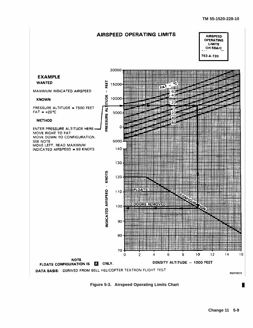
TM 55-1520-228-10
Figure 5-3. Airspeed Operating Limits Chart
Change 11 5-9
TM 55-1520-228-10
SECTION VI MANEUVERING
5-22. AEROBATIC MANEUVERS.
Aerobatic maneuvers are prohibited. Aerobatic f ightis def ned to be any intentional maneuver involving anabrupt change in aircraft attitude, an abnormal attitude,pitch angel greater than ±30° or roll angles greater than60°, or abnormal acceleration not necessary for normalf ight.
5-23. CONTROL MOVEMENTS.
For gross weights greater than 3000 lbs. anddensity altitudes greater than sea level, the di-rectional control margin may be signif cantly re-duced while hovering in winds from the rightgreater than 20 knots or for right sideward f ightat speed greater than 20 knots.
5-24. HOVERING LIMITATIONS.
Ten percent of total pedal travel, full right to full left, isconsidered adequate for safe control. The rearward air-speed limit is 30 knots and sideward limit is 35 knotsexcept that control is marginal for certain combinationsof relative wind velocity and azimuth angles (measuredclockwise from the nose of the helicopter). See Chap-ter 8 for a description of the marginal wind velocity andazimuth angles.
5-25. FLIGHT RESTRICTIONS AT LOW “G’S”.
Flight at less than +0.5g is prohibited.
5-26. FLIGHT RESTRICTIONS FOR PRACTICEAUTOROTATION LANDINGS. (FIGURE 5-4.)
a. A qualif ed OH-58A/C IP must be in position totake control of the aircraft.
b. Reported surface winds must not exceed 20knots.
c. Surface crosswind component must not exceed10 knots. Wind gust spread must not exceed 10 knots.
d. Touchdown rotor RPM must not be less than64%.
e. Ground speed at touchdown should be approxi-mately 5 knots.
f. Airspeed during glide shall not be less than thatestablished for minimum rate of descent.
In any event, relatively long ground runs with thecollective up, or any tendency to f oat for longdistance prior to skid contact should be avoided.If vibrations are encountered after touchdownimmediate lowering of the collective is recom-mended.
g. Upon ground contact, collective pitch must be re-duced smoothly to bottom stop without delay while main-taining cyclic pitch near center position. Application ofaft cyclic should be avoided.
h. Touchdown autorotations downwind are prohib-ited.
5-27. DELETED.
5-28. FLIGHT RESTRICTION FOR HIGH POWER.
NOTE
In aircraft equipped with IR exhaust stacks, rateof climb in excess of 1000 ft/min may result in di-vergent aircraft pitch oscillation which can reach20 to 30 degree attitudes. This divergence canbe alleviated by either increasing airspeed dur-ing steady climbs or decreasing rate of climb.Climb rates in excess of 1000 ft/min should beavoided.
5-10 Change 14
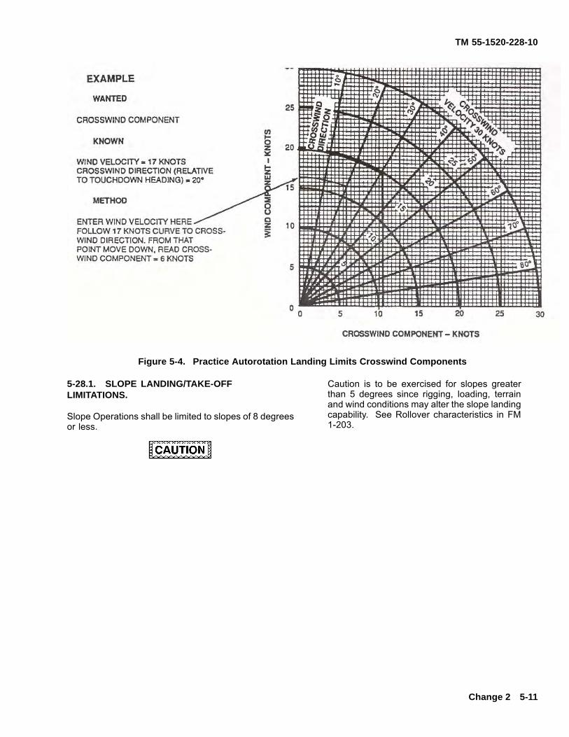
TM 55-1520-228-10
Figure 5-4. Practice Autorotation Landing Limits Crosswind Components
5-28.1. SLOPE LANDING/TAKE-OFFLIMITATIONS.
Slope Operations shall be limited to slopes of 8 degreesor less.
Caution is to be exercised for slopes greaterthan 5 degrees since rigging, loading, terrainand wind conditions may alter the slope landingcapability. See Rollover characteristics in FM1-203.
Change 2 5-11
TM 55-1520-228-10
SECTION VII ENVIRONMENTAL RESTRICTIONS
5-29. FLIGHT UNDER INSTRUMENTMETEOROLOGICAL CONDITIONS (IMC).
This aircraft is restricted to visual f ight conditions. Flightinto instrument meteorological conditions will be con-ducted on an emergency basis only.
5-30. FLIGHT RESTRICTIONS IN FALLING ORBLOWING SNOW.
Flight in falling or blowing snow is prohibited except forthose helicopters with reverse f ow inlet fairing installed.Helicopters having the above features may be f own infalling or blowing snow provided reverse f ow inlet fair-ings are installed and the following criteria is met.
a. Visibility reduced by snow must be at least 1/2mile.
b. Prior to initial takeoff and each subsequent take-off, inspect the engine as specif ed in Chapter 8, SectionV, paragraph 8-34.
(1) Deleted.
(2) Deleted.
(3) Deleted.
5-31. FLIGHT OVER SALT WATER.
Prolonged hovering over salt water which re-sults in spray ingestion, indicated by spray onthe windshield, should be avoided.
Salt spray ingestion in turbine engines may result in adeterioration in performance as well as a loss in com-pressor stall margin. When operating within 10 miles ofsalt water or within 200 miles of volcanic activity appro-priate entries should be made on DA Form 2408-13-1 toalert maintenance.
5-32. FLIGHT IN SAND AND DUST CONDITIONS.
During operations in heavy sand or dusty conditionswithout the new improved nozzles will result in lowerinlet particle separator (IPS) eff ciency which in turnseverely shortens the engine life.
5-32-1. FLIGHT IN RAIN, SNOW AND ICINGCONDITIONS.
If f own in rain, snow or icing conditions, appropriate en-tries should be made on DA Form 2408-13-1 to alertmaintenance.
5-33. TURBULENCE LIMITATIONS.
a. Intentional f ight into severe or extreme turbu-lence is prohibited.
b. Intentional f ight into moderate turbulence is notrecommended when report or forecast is based on air-craft above 12,500 pounds gross weight.
c. Intentional f ight into thunderstorms is prohibited.
5-12 Change 14
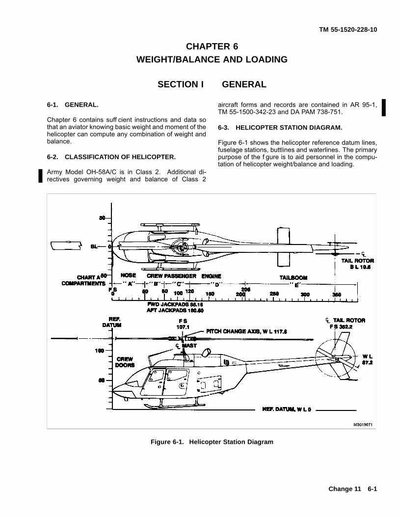
TM 55-1520-228-10
CHAPTER 6WEIGHT/BALANCE AND LOADING
SECTION I GENERAL
6-1. GENERAL.
Chapter 6 contains suff cient instructions and data sothat an aviator knowing basic weight and moment of thehelicopter can compute any combination of weight andbalance.
6-2. CLASSIFICATION OF HELICOPTER.
Army Model OH-58A/C is in Class 2. Additional di-rectives governing weight and balance of Class 2
aircraft forms and records are contained in AR 95-1,TM 55-1500-342-23 and DA PAM 738-751.
6-3. HELICOPTER STATION DIAGRAM.
Figure 6-1 shows the helicopter reference datum lines,fuselage stations, buttlines and waterlines. The primarypurpose of the f gure is to aid personnel in the compu-tation of helicopter weight/balance and loading.
Figure 6-1. Helicopter Station Diagram
Change 11 6-1
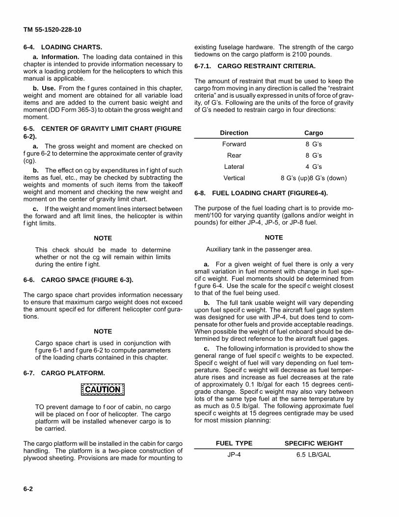
TM 55-1520-228-10
6-4. LOADING CHARTS.a. Information. The loading data contained in this
chapter is intended to provide information necessary towork a loading problem for the helicopters to which thismanual is applicable.
b. Use. From the f gures contained in this chapter,weight and moment are obtained for all variable loaditems and are added to the current basic weight andmoment (DD Form 365-3) to obtain the gross weight andmoment.
6-5. CENTER OF GRAVITY LIMIT CHART (FIGURE6-2).
a. The gross weight and moment are checked onf gure 6-2 to determine the approximate center of gravity(cg).
b. The effect on cg by expenditures in f ight of suchitems as fuel, etc., may be checked by subtracting theweights and moments of such items from the takeoffweight and moment and checking the new weight andmoment on the center of gravity limit chart.
c. If the weight and moment lines intersect betweenthe forward and aft limit lines, the helicopter is withinf ight limits.
NOTE
This check should be made to determinewhether or not the cg will remain within limitsduring the entire f ight.
6-6. CARGO SPACE (FIGURE 6-3).
The cargo space chart provides information necessaryto ensure that maximum cargo weight does not exceedthe amount specif ed for different helicopter conf gura-tions.
NOTE
Cargo space chart is used in conjunction withf gure 6-1 and f gure 6-2 to compute parametersof the loading charts contained in this chapter.
6-7. CARGO PLATFORM.
TO prevent damage to f oor of cabin, no cargowill be placed on f oor of helicopter. The cargoplatform will be installed whenever cargo is tobe carried.
The cargo platform will be installed in the cabin for cargohandling. The platform is a two-piece construction ofplywood sheeting. Provisions are made for mounting to
existing fuselage hardware. The strength of the cargotiedowns on the cargo platform is 2100 pounds.
6-7.1. CARGO RESTRAINT CRITERIA.
The amount of restraint that must be used to keep thecargo from moving in any direction is called the “restraintcriteria” and is usually expressed in units of force of grav-ity, of G’s. Following are the units of the force of gravityof G’s needed to restrain cargo in four directions:
Direction Cargo
Forward 8 G’s
Rear 8 G’s
Lateral 4 G’s
Vertical 8 G’s (up)8 G’s (down)
6-8. FUEL LOADING CHART (FIGURE6-4).
The purpose of the fuel loading chart is to provide mo-ment/100 for varying quantity (gallons and/or weight inpounds) for either JP-4, JP-5, or JP-8 fuel.
NOTE
Auxiliary tank in the passenger area.
a. For a given weight of fuel there is only a verysmall variation in fuel moment with change in fuel spe-cif c weight. Fuel moments should be determined fromf gure 6-4. Use the scale for the specif c weight closestto that of the fuel being used.
b. The full tank usable weight will vary dependingupon fuel specif c weight. The aircraft fuel gage systemwas designed for use with JP-4, but does tend to com-pensate for other fuels and provide acceptable readings.When possible the weight of fuel onboard should be de-termined by direct reference to the aircraft fuel gages.
c. The following information is provided to show thegeneral range of fuel specif c weights to be expected.Specif c weight of fuel will vary depending on fuel tem-perature. Specif c weight will decrease as fuel temper-ature rises and increase as fuel decreases at the rateof approximately 0.1 lb/gal for each 15 degrees centi-grade change. Specif c weight may also vary betweenlots of the same type fuel at the same temperature byas much as 0.5 lb/gal. The following approximate fuelspecif c weights at 15 degrees centigrade may be usedfor most mission planning:
FUEL TYPE SPECIFIC WEIGHT
JP-4 6.5 LB/GAL
6-2

TM 55-1520-228-10
— Continued
FUEL TYPE SPECIFIC WEIGHT
JP-5 6.7 LB/GAL
JP-8 6.7 LB/GAL
Change 14 6-2
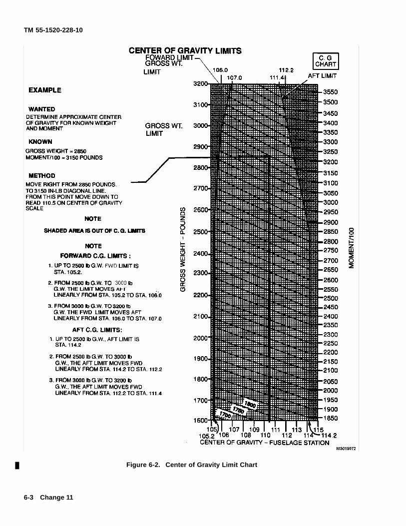
TM 55-1520-228-10
Figure 6-2. Center of Gravity Limit Chart
6-3 Change 11
TM 55-1520-228-10
Figure 6-3. Cargo Space
Change 10 6-4
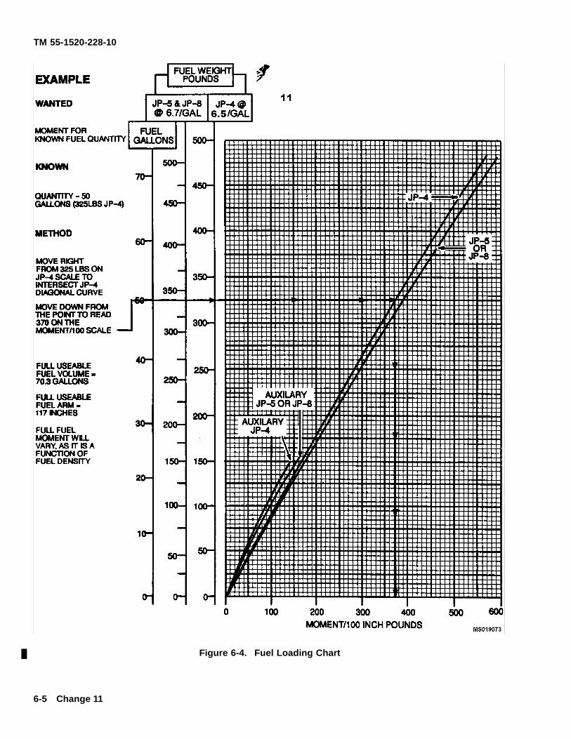
TM 55-1520-228-10
Figure 6-4. Fuel Loading Chart
6-5 Change 11
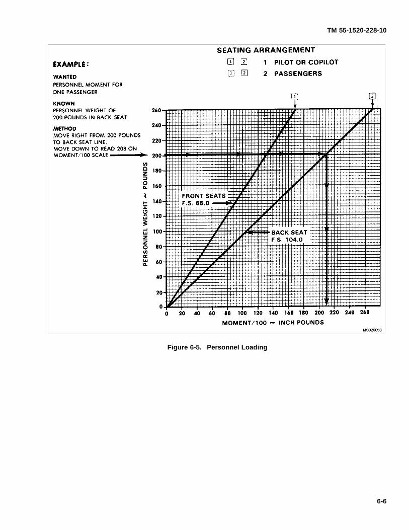
TM 55-1520-228-10
Figure 6-5. Personnel Loading
6-6
TM 55-1520-228-10
6-9. OIL DATA.
For weight and balance purposes, engine oil is part ofaircraft basic weight.
6-10. PERSONNEL LOADING (FIGURE 6-5).
Refer to f gure 6-5, to compute pilot, copilot/observerand passenger moments.
NOTE
When helicopter is operated at critical grossweights, the exact weight of each individualoccupant plus equipment should be used. Ifweighting facilities are not available, or if thetactical situation dictates otherwise, loads shallbe computed as follows:
a. Combat equipped soldiers; 240 lbs. per individ-ual.
b. Combat equipped paratroopers; 260 lbs. per in-dividual.
c. Crew and passengers with no equipment: com-pute weight according to each individual’s estimate.
6-11. DELETED.
6-12. DELETED.
6-12.1. DELETED.
6-13. CARGO MOMENT.
Refer to Cargo Moment Chart, f gure 6-8, for computingcargo weight and balance information.
6-7 Change 11
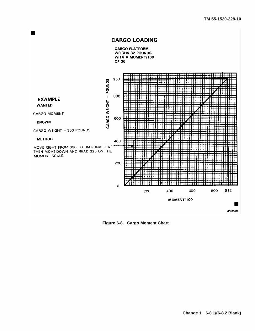
TM 55-1520-228-10
Figure 6-8. Cargo Moment Chart
Change 1 6-8.1/(6-8.2 Blank)


TM 55-1520-228-10
SECTION II DD FORM 365
6-14. DD FORM 365-1 – BASIC WEIGHT CHECKLIST.
The form is a tabulation of equipment that is, or maybe, installed and for which provision for f xed stowagehas been made in a def nite location. The form givesthe weight, arm, and moment/100 of individual items foruse in correcting the basic weight and moment on DDForm 365-3 as changes are made in this equipment.
6-15. DD FORM 365-3 – BASIC WEIGHT ANDBALANCE RECORD.
The form is a continuous history of the basic weightand moment resulting from structural and equipment
changes. At all times the last entry is considered currentweight and balance status of the basic helicopter.
6-16. DD FORM 365-4 – WEIGHT AND BALANCECLEARANCE FORM F.
The form is a summary of actual disposition of the loadin the helicopter. It records the balance status of thehelicopter, step-by-step. It serves as a worksheet onwhich to record weight and balance calculations, andany corrections that must be made to ensure that thehelicopter will be within weight and cg limits.
Change 10 6-9/(6-10 Blank)

TM 55-1520-228-10
CHAPTER 7PERFORMANCE DATA
SECTION I INTRODUCTION
NOTE
All OH-58A and OH-58C model aircraft are nowequipped with the T63-A-720 Engine. For per-formance planning purposes, all OH-58A modelaircraft will use the OH-58C model aircraft C.performance charts.
7-1. PURPOSE.
The purpose of this chapter is to provide the best avail-able performance data for the OH-58A/C helicopter.Regular use of this information will enable you to re-ceive maximum safe utilization from aircraft. Althoughmaximum performance is not always required, regularuse of this chapter is recommended for the followingreasons.
a. Knowledge of your performance margin will al-low you to make better decisions when unexpected con-ditions or alternate missions are encountered.
b. Situations requiring maximum performance willbe readily recognized.
c. Familiarity with the data will allow performanceto be computed more easily and quickly.
d. Experience will be gained in accurately estimat-ing the effects of variables for which data are not pre-sented.
NOTE
The information provided in this chapter is pri-marily intended for mission planning and is mostuseful when planning operations in unfamiliarareas or at extreme conditions. The data mayalso be used in f ight, to establish unit or areasstanding operating procedures, and to informground commanders of performance/risk trade-offs.
7-2. CHAPTER 7 INDEX.
The following index contains a list of the sections andtheir respective titles, along with f gure numbers, sub-jects and page numbers for each performance chartcontained in this chapter.
INDEX
Section Subject Page
I Introduction . . . . . . . . . . . . . . . . . . . . . . . . . . . . . . . . . . . . . . . . . . . . . . . . . . . . . . . . . . . . . . . . . . . 7-1
II Temperature Conversion . . . . . . . . . . . . . . . . . . . . . . . . . . . . . . . . . . . . . . . . . . . . . . . . . . . . . . . 7-6
Figure 7-1. Temperature Conversion Chart . . . . . . . . . . . . . . . . . . . . . . . . . . . . . . . . . . . 7-7
III-IX T63-A-700 Engine A. Performance Charts . . . . . . . . . . . . . . . . . . . . . . . . . . . . . . . . . . . . . . . . DELETED
X Torque Available C. . . . . . . . . . . . . . . . . . . . . . . . . . . . . . . . . . . . . . . . . . . . . . . . . . . . . . . . . . . . . 7-47
Figure 7-11. Maximum Torque available (30 Minute Operation) Chart C.
Sheet 1 of 4, Engine Deice and Heater OFF . . . . . . . . . . . . . . . . . . . . . . . . . . . . . . 7-48
Sheet 2 of 4, Engine Deice and Heater ON . . . . . . . . . . . . . . . . . . . . . . . . . . . . . . . 7-49
Sheet 3 of 4, Engine Deice and Heater OFF and Reverse Flow Inlet Installed 7-50
Sheet 4 of 4, Engine Deice and Heater ON and Reverse Flow Inlet Installed . 7-51
Figure 7-12. Torque Available (Continuous Operation) Chart C.
Sheet 1 of 4, Engine Deice and Heater OFF . . . . . . . . . . . . . . . . . . . . . . . . . . . . . . 7-52
Sheet 2 of 4, Engine Deice and Heater ON . . . . . . . . . . . . . . . . . . . . . . . . . . . . . . . 7-53
Sheet 3 of 4, Engine Deice and Heater OFF and Reverse Flow Inlet Installed 7-54
Sheet 4 of 4, Engine Deice and Heater ON and Reverse Flow Inlet Installed . 7-55
Change 11 7-1
TM 55-1520-228-10
INDEX — Continued
Section Subject Page
XI Hover . . . . . . . . . . . . . . . . . . . . . . . . . . . . . . . . . . . . . . . . . . . . . . . . . . . . . . . . . . . . . . . . . . . . . . . . . 7-56
Figure 7-13. Hover Chart C.
Sheet 1 of 3, Hover Chart . . . . . . . . . . . . . . . . . . . . . . . . . . . . . . . . . . . . . . . . . . . . . . . 7-57
Sheet 2 of 3, Hover Chart . . . . . . . . . . . . . . . . . . . . . . . . . . . . . . . . . . . . . . . . . . . . . . . 7-58
Sheet 3 of 3, Hover Chart . . . . . . . . . . . . . . . . . . . . . . . . . . . . . . . . . . . . . . . . . . . . . . . 7–59
XII Takeoff (not applicable) . . . . . . . . . . . . . . . . . . . . . . . . . . . . . . . . . . . . . . . . . . . . . . . . . . . . . . . . . 7-60
Figure 7-14 Takeoff Chart . . . . . . . . . . . . . . . . . . . . . . . . . . . . . . . . . . . . . . . . . . . . . . . . . . DELETED
XIII Cruise . . . . . . . . . . . . . . . . . . . . . . . . . . . . . . . . . . . . . . . . . . . . . . . . . . . . . . . . . . . . . . . . . . . . . . . . 7-62
Figure 7-15. Cruise Chart C.
Sheet 1 of 13, Pressure Altitude Sea Level to 2000 Ft, FAT = -30°C . . . . . . . . . 7-63
Sheet 2 of 13, Pressure Altitude 4000 Ft to 6000 Ft, FAT = -30°C . . . . . . . . . . . 7-64
Sheet 3 of 13, Pressure Altitude 8000 Ft to 14,000 Ft, FAT = -30°C . . . . . . . . . 7-65
Sheet 4 of 13, Pressure Altitude Sea Level to 6000 Ft, FAT = -15°C . . . . . . . . . 7-66
Sheet 5 of 13, Pressure Altitude 8000 Ft to 14,000 Ft, FAT = -15°C . . . . . . . . . 7-67
Sheet 6 of 13, Pressure Altitude Sea Level to 6000 Ft, FAT = 0°C . . . . . . . . . . 7-68
Sheet 7 of 13, Pressure Altitude 8000 Ft to 14,000 Ft, FAT = 0°C . . . . . . . . . . . 7-69
Sheet 8 of 13, Pressure Altitude Sea Level to 6000 Ft, FAT = +15°C . . . . . . . . 7-70
Sheet 9 of 13, Pressure Altitude 8000 Ft to 14,000 Ft, FAT = +15°C . . . . . . . . . 7-71
Sheet 10 of 13, Pressure Altitude Sea Level to 6000 Ft, FAT = +30°C . . . . . . . 7-72
Sheet 11 of 13, Pressure Altitude 8000 Ft to 14,000 Ft, FAT = +30°C . . . . . . . 7-73
Sheet 12 of 13, Pressure Altitude Sea Level to 6000 Ft, FAT = +45°C . . . . . . . 7-74
Sheet 13 of 13, Pressure Altitude 8000 Ft to 14,000 Ft, FAT = +45°C . . . . . . . 7-75
XIV Drag C. . . . . . . . . . . . . . . . . . . . . . . . . . . . . . . . . . . . . . . . . . . . . . . . . . . . . . . . . . . . . . . . . . . . . . . . 7-76
Figure 7-16. Drag Chart . . . . . . . . . . . . . . . . . . . . . . . . . . . . . . . . . . . . . . . . . . . . . . . . . . . . 7-77
XV Climb — Descent . . . . . . . . . . . . . . . . . . . . . . . . . . . . . . . . . . . . . . . . . . . . . . . . . . . . . . . . . . . . . . 7-78
Figure 7-17. Climb — Descent Chart C. . . . . . . . . . . . . . . . . . . . . . . . . . . . . . . . . . . . . . 7-79
Figure 7-18. Climb Performance C. . . . . . . . . . . . . . . . . . . . . . . . . . . . . . . . . . . . . . . . . . . DELETED
XVI Idle Fuel Flow . . . . . . . . . . . . . . . . . . . . . . . . . . . . . . . . . . . . . . . . . . . . . . . . . . . . . . . . . . . . . . . . . 7-84
Figure 7-19. Idle Fuel Flow Chart C. . . . . . . . . . . . . . . . . . . . . . . . . . . . . . . . . . . . . . . . . . 7-85
7-2 Change 11
TM 55-1520-228-10
7-3. GENERAL.
The data presented covers the maximum range of condi-tions and performance that can reasonably be expected.In each area of performance, the effects altitude, tem-perature, gross weight, and other parameters relating tothat phase of f ight are presented. In addition to the pre-sented data, your judgement and experience will be nec-essary to accurately obtain performance under a givenset of circumstances. The conditions for the data arelisted under the title of each chart. The effects of dif-ferent conditions are discussed in the text accompany-ing each phase of performance. Where practical, dataare presented at conservative conditions. However, NOGENERAL CONSERVATISM HAS BEEN APPLIED. Allperformance data presented are within the applicablelimits of the aircraft.
7-4. LIMITS.
Applicable limits are shown on the charts as red lines.Performance generally deteriorates rapidly beyond lim-its. If limits are exceeded, minimize the amount andtime. Enter the maximum value and time above limitson DA Form 2408-13 so proper maintenance action canbe taken.
7-5. USE OF CHARTS.
a. Chart Explanation. The f rst page of each sec-tion describes the chart(s) and explains its uses.
b. Color Coding. Chart color codes are used as fol-lows:
(1) Green is used for example guidelines.
(2) Red is used for limit lines.
(3) Yellow is used for precautionary or time-lim-ited operations.
c. Reading the Charts. The primary use of eachchart is given in an example and green guidelines isprovided to help you follow the route through the chart.The use of a straight (ruler or page edge) and a hardf ne point pencil is recommended to avoid cumulativeerrors. The majority of the charts provide a standardpattern for use as follows: enter f rst variable on top leftscale, move right to the second variable, ref ect downat right angles to the third variable, ref ect left at right
angles to the fourth variable, ref ect down, etc. until thef nal variable is read out at the f nal scale. In addition theprimary use, other uses of each chart are explained inthe text accompanying each set of performance charts.Colored registration blocks located at the bottom and topof each chart are used to determine if slippage has oc-curred during printing. If slippage has occurred, refer tochapter 5 for correct operating limits
NOTE
An example of an auxiliary use of the chartsreferenced above is as follows: Although thehover chart is primarily arranged to f nd torquerequired to hover, by entering torque availableas torque required, maximum skid height forhover can also be found. In general, any singlevariable can be found if all others are known.Also, the tradeoffs between two variables canbe found. For example, at a given densityaltitude and pressure altitude, you can f nd themaximum gross weight capability as free airtemperatures change.
The primary advantage of the helicopter overother aircraft is the capability to hover and take-off and land vertically (zero air speed f ight). Tomore rapidly calculate the performance trade-offs in hover mode, a Hover Ceiling Chart hasbeen included.
7-6. DATA BASIS.
The type of data used is indicated at the bottom of eachperformance chart under DATA BASIS. The applicablereport and date of the data are also given. The dataprovided generally is based on one of four categories.
a. Flight Test Data. Data obtained by f ight test ofthe aircraft by experience f ight test personnel at preciseconditions using sensitive calibrated instruments.
b. Derived From Flight Test. Flight test data ob-tained on a similar rather than the same aircraft and se-ries. Generally small corrections will have been made.
c. Calculated Data. Data based on tests, but not onf ight test of the complete aircraft.
d. Estimated Data. Data based on estimates usingaerodynamic theory or other means but not verif ed bytest f ight.
7-4
TM 55-1520-228-10
7-7. SPECIFIC CONDITIONS.
The data presented are accurate only for specif c con-ditions listed under the title of each chart. Variablesfor which data are not presented, but which may affectthat phase of performance, are discussed in the text.Where data are available or reasonable estimates canbe made, the amount that each variable affects perfor-mance will be given.
7-8. GENERAL CONDITIONS.
In addition to the specif c conditions, the following gen-eral conditions are applicable to the performance data.
a. Rigging. All airframe and engine controls are as-sumed to be rigged within allowable tolerances.
b. Pilot Technique. Normal pilot technique is as-sumed. Control movements should be smooth and con-tinuous.
c. Aircraft Variation. Variations in performance be-tween individual aircraft are known to exist; however,they are considered to be small and cannot be individu-ally accounted for.
d. Instrument Variation. The data shown in theperformance charts do not account for instrument inac-curacies or malfunctions.
e. Types of Fuel. All f ight performance data isbased on JP-4 fuel. The change in fuel f ow and torqueavailable , when using JP-5, JP-8, Aviation gasoline, orany other approved fuels, is insignif cant.
7-9. PERFORMANCE DISCREPANCIES.
Regular use of this chapter will allow you to monitorinstruments and other aircraft systems for malfunction,by comparing actual performance with planned perfor-mance. Knowledge will also be gained concerning theeffects of variables for which data are not provided,thereby increasing the accuracy of performance predic-tions.
7-10. DEFINITIONS OF ABBREVIATIONS.
a. Unless otherwise indicated in the following list ofabbreviations, abbreviations and symbols used in thismanual conform to those established in Military Stan-dard MIL-STD-12, which is periodically revised to ref ectcurrent changes in abbreviations usage. Accordingly,it may not be noted that certain previously establisheddef nitions have been replaced by more current abbre-viations and symbols.
b. Capitalization and punctuation of abbreviationsvaries, depending upon the context in which they areused. In general, lower case abbreviations are usedin text material, whereas abbreviations used in chartsand illustrations appear in full capital letters. Periodsdo not usually follow abbreviation; however, periods areused with abbreviations that could be mistaken for wholewords if the were omitted.
c. The following list provides def nitions for abbre-viations used in this manual. The same abbreviation ap-plies for either singular or plural applications.
LIST OF ABBREVIATIONS
Abbreviation De nition Abbreviation De nition
AGL Above ground level FAT Free air temperature
ALT Altitude FLT Flight
AVAIL Available FT Foot
C Celsius FT/MIN Foot per minute
CAS Calibrated FWD Forward
CL Centerline ∆F Increment of equivalent f at
CONFIG Conf guration plate drag area
CONT Continuous GAL Gallon
ECU Environmental Control Unit GAL/HR Gallons per hour
END Endurance GW Gross Weight
F Fahrenheit HP Horsepower
HR Hour NM Nautical Mile
7-6 Change 11
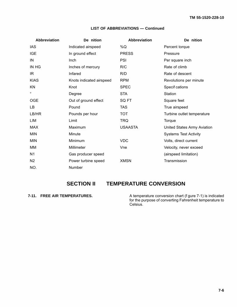
TM 55-1520-228-10
LIST OF ABBREVIATIONS — Continued
Abbreviation De nition Abbreviation De nition
IAS Indicated airspeed %Q Percent torque
IGE In ground effect PRESS Pressure
IN Inch PSI Per square inch
IN HG Inches of mercury R/C Rate of climb
IR Infared R/D Rate of descent
KIAS Knots indicated airspeed RPM Revolutions per minute
KN Knot SPEC Specif cations
° Degree STA Station
OGE Out of ground effect SQ FT Square feet
LB Pound TAS True airspeed
LB/HR Pounds per hour TOT Turbine outlet temperature
LIM Limit TRQ Torque
MAX Maximum USAASTA United States Army Aviation
MIN Minute Systems Test Activity
MIN Minimum VDC Volts, direct current
MM Millimeter Vne Velocity, never exceed
N1 Gas producer speed (airspeed limitation)
N2 Power turbine speed XMSN Transmission
NO. Number
SECTION II TEMPERATURE CONVERSION
7-11. FREE AIR TEMPERATURES. A temperature conversion chart (f gure 7-1) is indicatedfor the purpose of converting Fahrenheit temperature toCelsius.
7-6
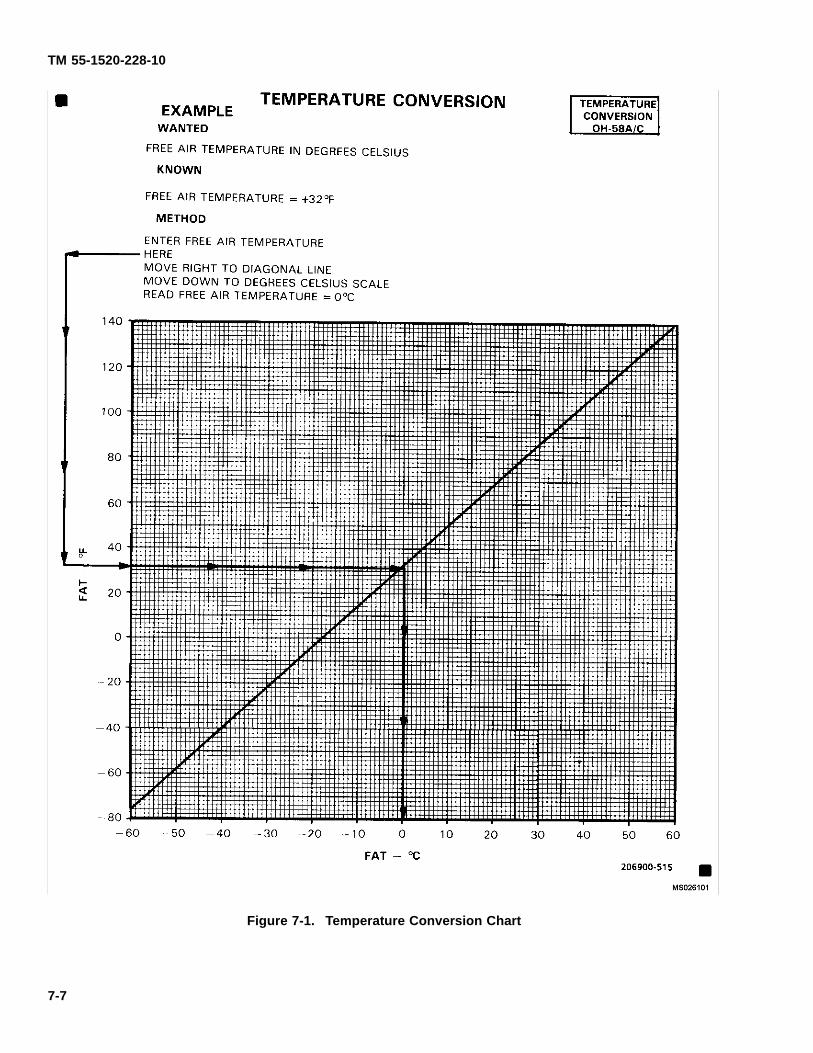
TM 55-1520-228-10
Figure 7-1. Temperature Conversion Chart
7-7

TM 55-1520-228-10
PAGES 7-8 THROUGH 7-46, INCLUDING PARA-GRAPHS 7-12 THROUGH 7-36 AND FIGURES 7-2THROUGH 7-10, HAVE BEEN DELETED.
7-8
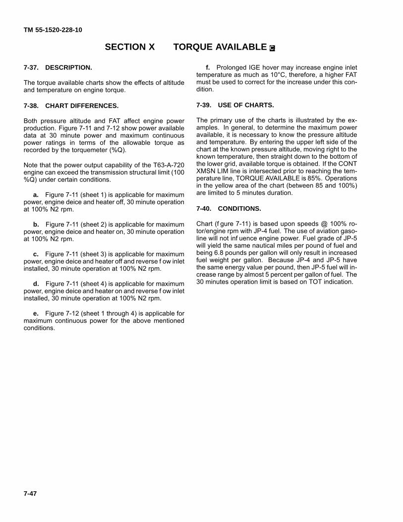
TM 55-1520-228-10
SECTION X TORQUE AVAILABLE C.
7-37. DESCRIPTION.
The torque available charts show the effects of altitudeand temperature on engine torque.
7-38. CHART DIFFERENCES.
Both pressure altitude and FAT affect engine powerproduction. Figure 7-11 and 7-12 show power availabledata at 30 minute power and maximum continuouspower ratings in terms of the allowable torque asrecorded by the torquemeter (%Q).
Note that the power output capability of the T63-A-720engine can exceed the transmission structural limit (100%Q) under certain conditions.
a. Figure 7-11 (sheet 1) is applicable for maximumpower, engine deice and heater off, 30 minute operationat 100% N2 rpm.
b. Figure 7-11 (sheet 2) is applicable for maximumpower, engine deice and heater on, 30 minute operationat 100% N2 rpm.
c. Figure 7-11 (sheet 3) is applicable for maximumpower, engine deice and heater off and reverse f ow inletinstalled, 30 minute operation at 100% N2 rpm.
d. Figure 7-11 (sheet 4) is applicable for maximumpower, engine deice and heater on and reverse f ow inletinstalled, 30 minute operation at 100% N2 rpm.
e. Figure 7-12 (sheet 1 through 4) is applicable formaximum continuous power for the above mentionedconditions.
f. Prolonged IGE hover may increase engine inlettemperature as much as 10°C, therefore, a higher FATmust be used to correct for the increase under this con-dition.
7-39. USE OF CHARTS.
The primary use of the charts is illustrated by the ex-amples. In general, to determine the maximum poweravailable, it is necessary to know the pressure altitudeand temperature. By entering the upper left side of thechart at the known pressure altitude, moving right to theknown temperature, then straight down to the bottom ofthe lower grid, available torque is obtained. If the CONTXMSN LIM line is intersected prior to reaching the tem-perature line, TORQUE AVAILABLE is 85%. Operationsin the yellow area of the chart (between 85 and 100%)are limited to 5 minutes duration.
7-40. CONDITIONS.
Chart (f gure 7-11) is based upon speeds @ 100% ro-tor/engine rpm with JP-4 fuel. The use of aviation gaso-line will not inf uence engine power. Fuel grade of JP-5will yield the same nautical miles per pound of fuel andbeing 6.8 pounds per gallon will only result in increasedfuel weight per gallon. Because JP-4 and JP-5 havethe same energy value per pound, then JP-5 fuel will in-crease range by almost 5 percent per gallon of fuel. The30 minutes operation limit is based on TOT indication.
7-47
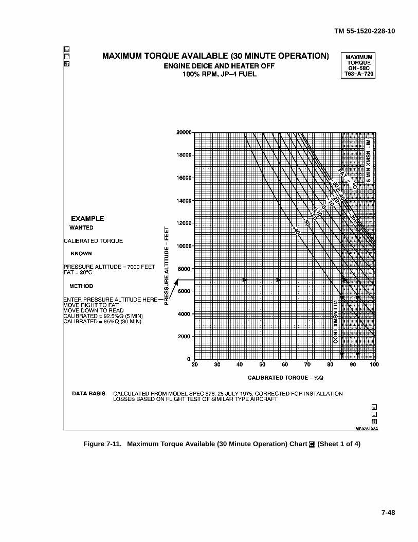
TM 55-1520-228-10
Figure 7-11. Maximum Torque Available (30 Minute Operation) Chart C. (Sheet 1 of 4)
7-48
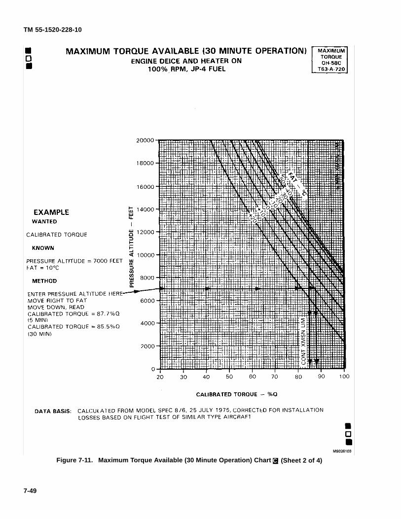
TM 55-1520-228-10
Figure 7-11. Maximum Torque Available (30 Minute Operation) Chart C. (Sheet 2 of 4)
7-49
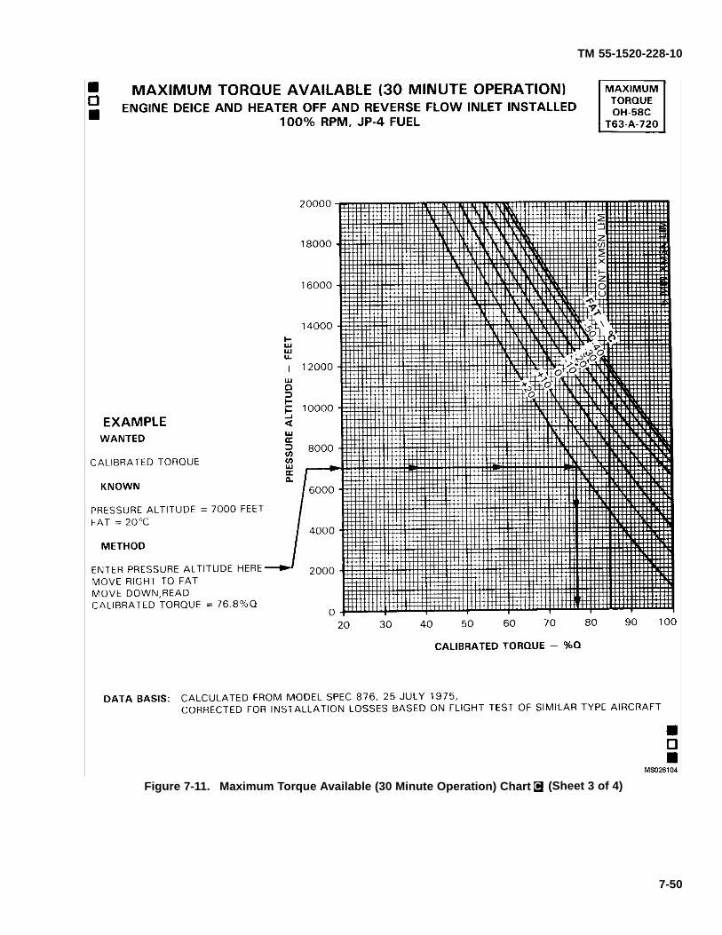
TM 55-1520-228-10
Figure 7-11. Maximum Torque Available (30 Minute Operation) Chart C. (Sheet 3 of 4)
7-50
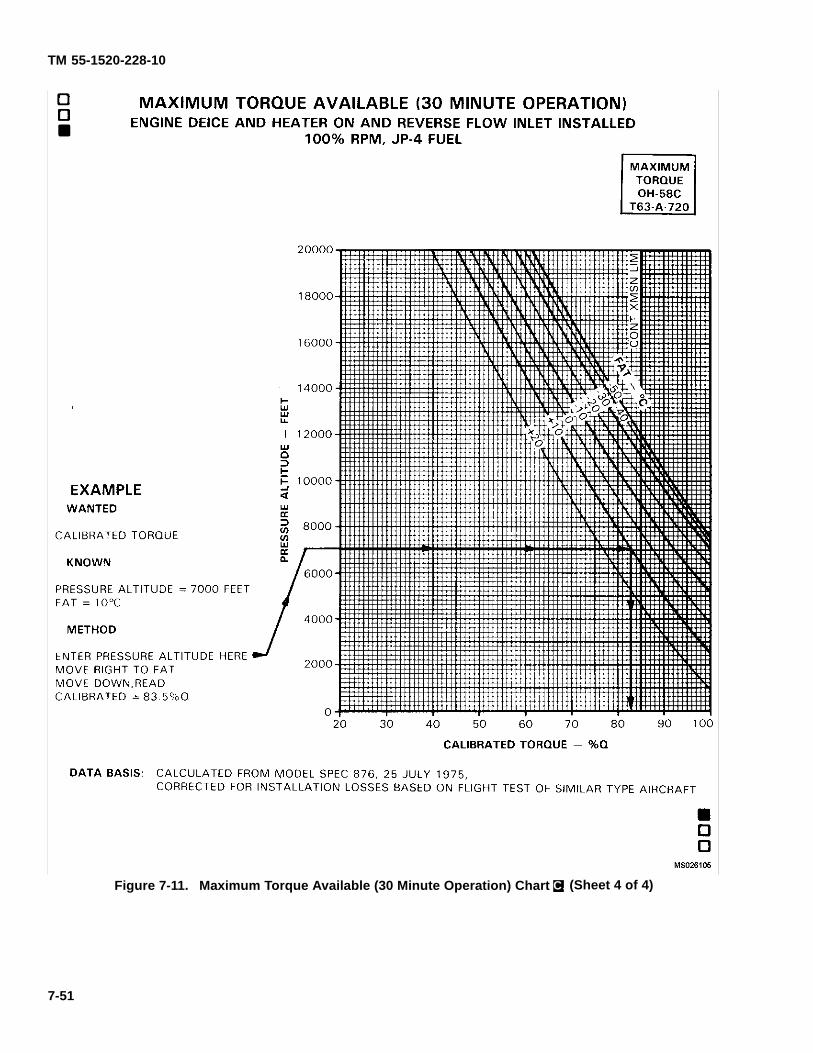
TM 55-1520-228-10
Figure 7-11. Maximum Torque Available (30 Minute Operation) Chart C. (Sheet 4 of 4)
7-51
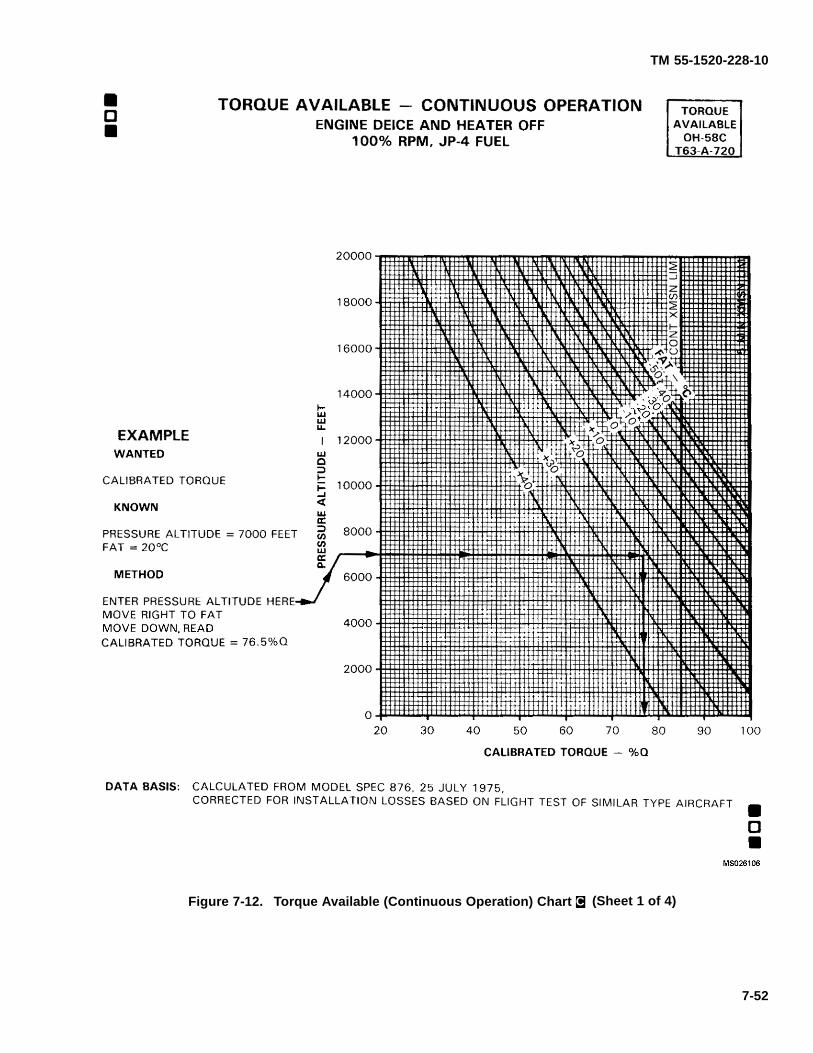
TM 55-1520-228-10
Figure 7-12. Torque Available (Continuous Operation) Chart C. (Sheet 1 of 4)
7-52
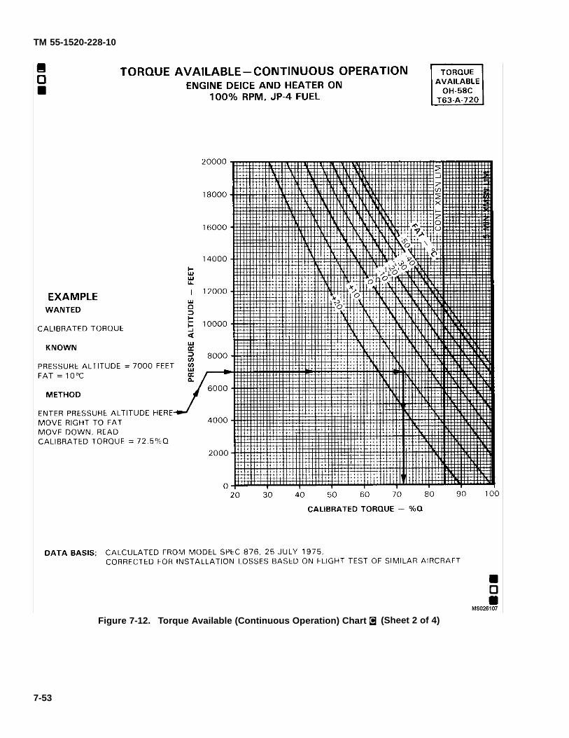
TM 55-1520-228-10
Figure 7-12. Torque Available (Continuous Operation) Chart C. (Sheet 2 of 4)
7-53
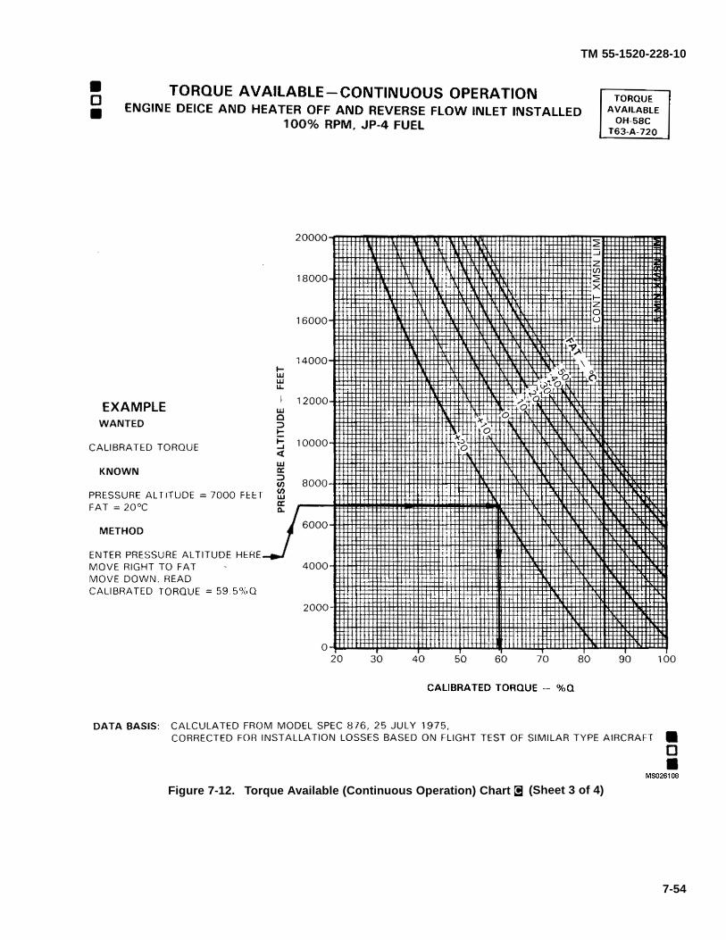
TM 55-1520-228-10
Figure 7-12. Torque Available (Continuous Operation) Chart C. (Sheet 3 of 4)
7-54
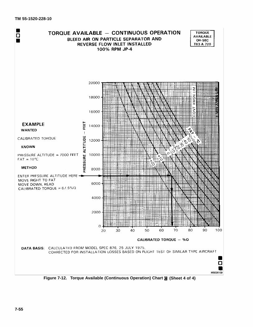
TM 55-1520-228-10
Figure 7-12. Torque Available (Continuous Operation) Chart C. (Sheet 4 of 4)
7-55
TM 55-1520-228-10
SECTION XI HOVER
7-41. DESCRIPTION.
The hover charts (f gure 7-13, sheets 1 and 2) show thehover ceiling and the torque required to hover respec-tively at various pressure altitudes, ambient tempera-tures, gross weights, and skid heights. Maximum skidheight for hover can also be obtained by using the torqueavailable from f gure 7-11.
7-42. USE OF CHART.
a. The primary use of the charts is illustrated bythe charts examples. In general, to determine to hoverceiling or the torque required to hover, it is necessary toknow the pressure altitude, temperature, gross weightand the desired skid height.
Low altitude maneuvering f ights at airspeedsbelow 35 knots are not recommended underconditions where power required to hover outof ground effect exceeds maximum continuouspower.
b. In addition to its primary use, the hover chart(sheet 2) can also be used to determine the predictedmaximum hover height, which is needed for use of thetakeoff chart (f gure 7-14); and the maximum right cross-wind corresponding to a 10% directional control mar-gin. To determine maximum right crosswind and hoverheight proceed as follows:
(1) Enter chart at appropriate pressure altitude.
(2) Move right to FAT.
(3) Move down to gross weight, read the maxi-mum right crosswind corresponding to a 10% directionalcontrol margin.
(4) Move left to intersection with maximumpower available (obtained form f gure 7-11).
(5) Read the predicted maximum skid height.This height is the maximum hover height.
7-43. CONDITIONS.
The hover charts are based upon calm wind conditions,a level ground surface, and the use of 100% N2 rpm.Controllability during downwind hover, crosswinds, side-ward f ight and rearward f ight may be inadequate; how-ever, for stabilized hover in steady winds from the right(i.e., right crosswind) the wind velocities on the chart cor-respond to the maximum one can have and yet maintaina 10% directional control margin. See Chapter 5 for hov-ering and low altitude/low airspeed f ight limitations.
Figure 7-13 (sheet 3 of 3) shows 10% directionalcontrol margins only for the stabilized conditionsset forth. It does not and is not meant to inferthat for corresponding dynamic f ight maneuver-ing conditions such margins exist.
7-56
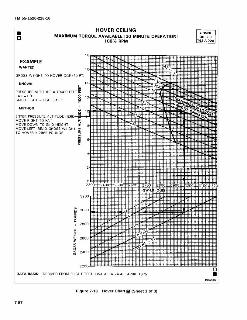
TM 55-1520-228-10
Figure 7-13. Hover Chart C. (Sheet 1 of 3)
7-57
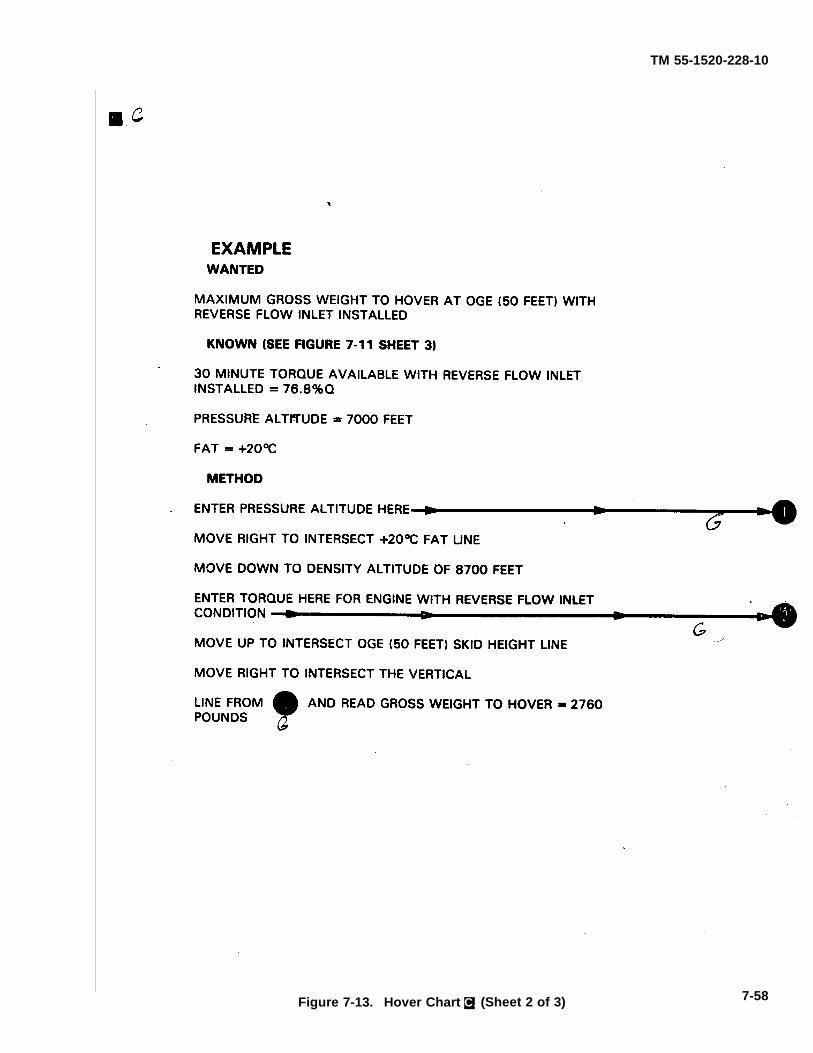
TM 55-1520-228-10
Figure 7-13. Hover Chart C. (Sheet 2 of 3) 7-58
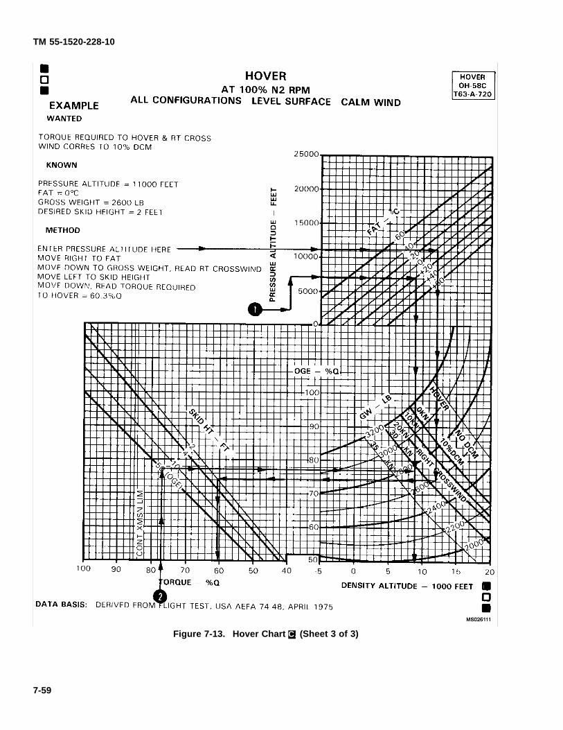
TM 55-1520-228-10
Figure 7-13. Hover Chart C. (Sheet 3 of 3)
7-59

TM 55-1520-228-10
SECTION XII TAKEOFF
7-44. DELETED.
7-45. DELETED.
7-46. DELETED.
FIGURE 7-14. ON PAGE 7-61 HAS BEEN DELETED.
7-60
TM 55-1520-228-10
SECTION XIII CRUISE
7-47. DESCRIPTION.
The cruise charts (f gure 7-15, sheets 1 through 13)show the torque pressure and engine rpm requiredfor level f ight at various pressure altitudes, airspeeds,gross weights, and fuel f ows.
NOTE
The cruise charts are basically arranged by FATgroupings, Figure 7-15, sheets 1 through 13,are based upon operation with clean conf gura-tion.
7-48. USE OF CHARTS.
The primary use of the charts is illustrated by the exam-ples provided in f gure 7-15. The f rst step for chart use isto select the proper chart, based upon the planned dragconf guration, pressure altitude, and anticipated free airtemperature; refer to chapter 7 index (paragraph 7-2).Normally, suff cient accuracy can be obtained by select-ing the chart nearest to the planned cruising altitude andFAT, or the next higher altitude and FAT (chart Exam-ple A, Method 2). If greater accuracy is required, inter-polation between altitudes and/or temperatures will berequired (chart Example A, Method 1). You may enterthe charts on any side: TAS, IAS, torque pressure, orfuel f ow, and then move vertically or horizontally to thegross weight, then to the other three parameters. Max-imum performance conditions are determined by enter-ing the chart where the maximum range or maximum en-durance and rate of climb lines intersect the appropriategross weight; then read airspeed, fuel f ow, and percenttorque. For conversation, use the gross weight at thebeginning of cruise f ight. For greater accuracy on longf ights it is preferable to determine cruise information forseveral f ight segments in order to allow for decreasingfuel weights (reduced gross weight). The following pa-rameters contained in each chart are further explainedas follows:
a. Airspeed. True and indicated airspeeds are pre-sented at opposite sides off each chart. On any chart,
indicated airspeed can be directly converted to true air-speed (or vice versa) by reading directly across the chartwithout regard for other chart information. maximumpermissible airspeed (Vne) limits appear as red lines onsome charts. If no red line appears, Vne is above thelimits of the chart.
b. Torque (%Q). Since pressure altitude and tem-perature are f xed for each chart, torque varies accord-ing to gross weight and airspeed.
c. Fuel Flow. Fuel f ow scales are provided oppo-site the torque scales. On any chart, torque may beconverted directly to fuel f ow without regard for otherchart information. All fuel f ow information is presentedwith engine deice and heater off. Fuel f ow increases5% with reverse f ow inlets installed, 4% with anti-iceon, and 4% with bleed air heater on.
d. Maximum Range. The maximum range lines in-dicate the combinations of weight and airspeed that willproduce the greatest f ight range per gallon of fuel underzero wind conditions. When a maximum range conditiondoes not appear on a chart it is because the maximumrange speed is beyond the maximum permissible speed(Vne) in such cases, Vne cruising speed to obtain max-imum range.
e. Maximum Endurance and Maximum Rate ofClimb. The maximum endurance and maximum rate ofclimb lines indicate the airspeed for minimum torque re-quired to maintain level f ight for each gross weight, FAT,and pressure altitude. Since minimum torque will pro-vide minimum fuel f ow, maximum f ight endurance willbe obtained at the airspeeds indicated.
7-49. CONDITIONS.
The cruise charts are based upon operation at 100%rpm, engine deice and heater off.
7-62 Change 11
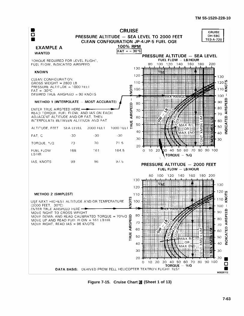
TM 55-1520-228-10
Figure 7-15. Cruise Chart C. (Sheet 1 of 13)
7-63
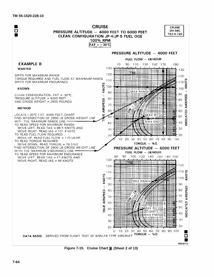
TM 55-1520-228-10
Figure 7-15. Cruise Chart C. (Sheet 2 of 13)
7-64
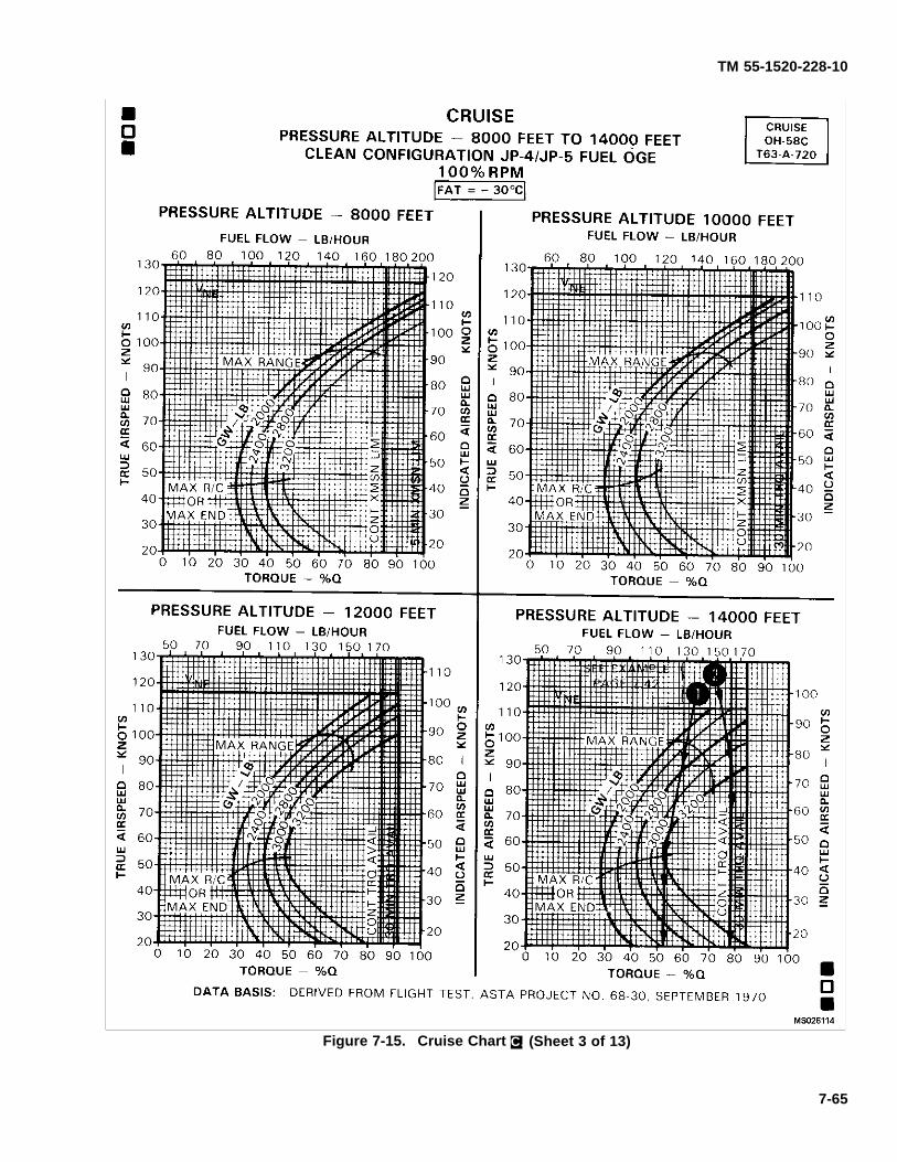
TM 55-1520-228-10
Figure 7-15. Cruise Chart C. (Sheet 3 of 13)
7-65
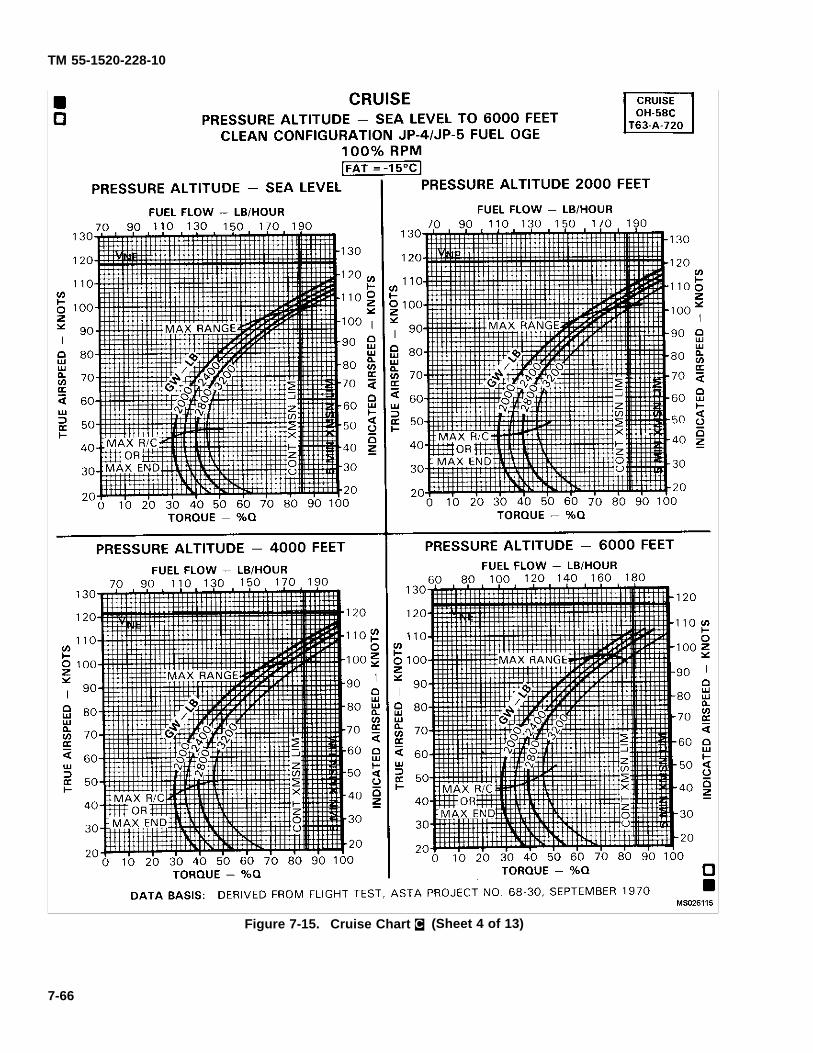
TM 55-1520-228-10
Figure 7-15. Cruise Chart C. (Sheet 4 of 13)
7-66
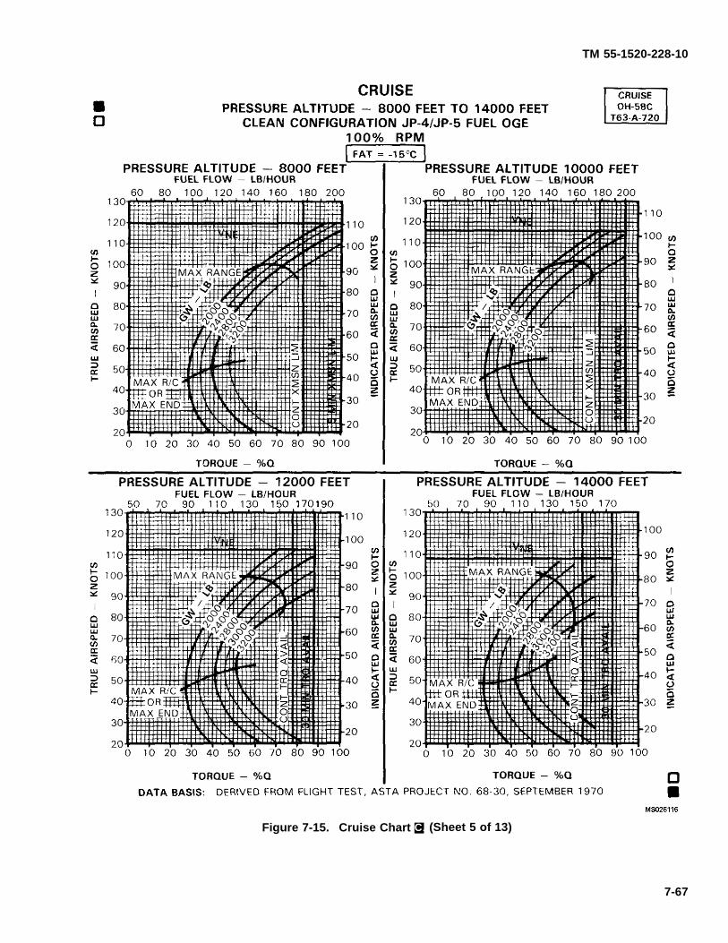
TM 55-1520-228-10
Figure 7-15. Cruise Chart C. (Sheet 5 of 13)
7-67
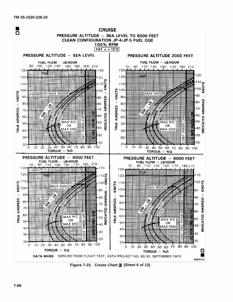
TM 55-1520-228-10
Figure 7-15. Cruise Chart C. (Sheet 6 of 13)
7-68
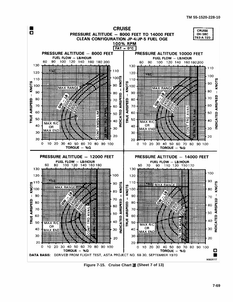
TM 55-1520-228-10
Figure 7-15. Cruise Chart C. (Sheet 7 of 13)
7-69
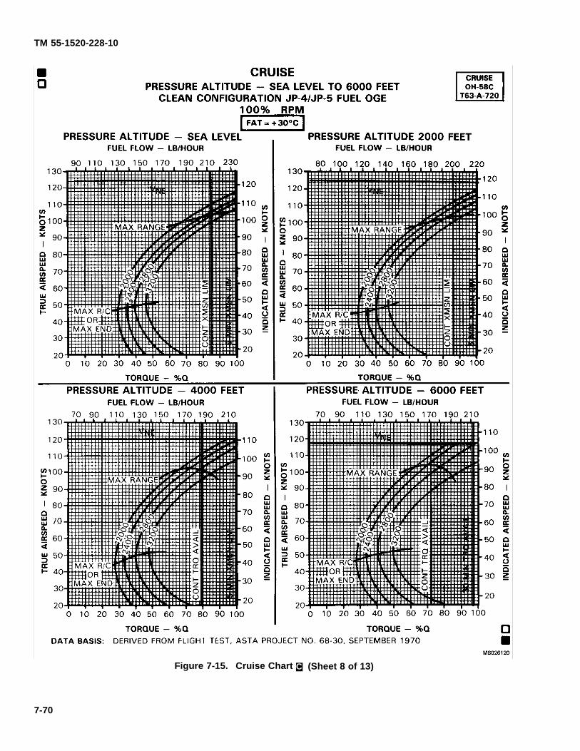
TM 55-1520-228-10
Figure 7-15. Cruise Chart C. (Sheet 8 of 13)
7-70
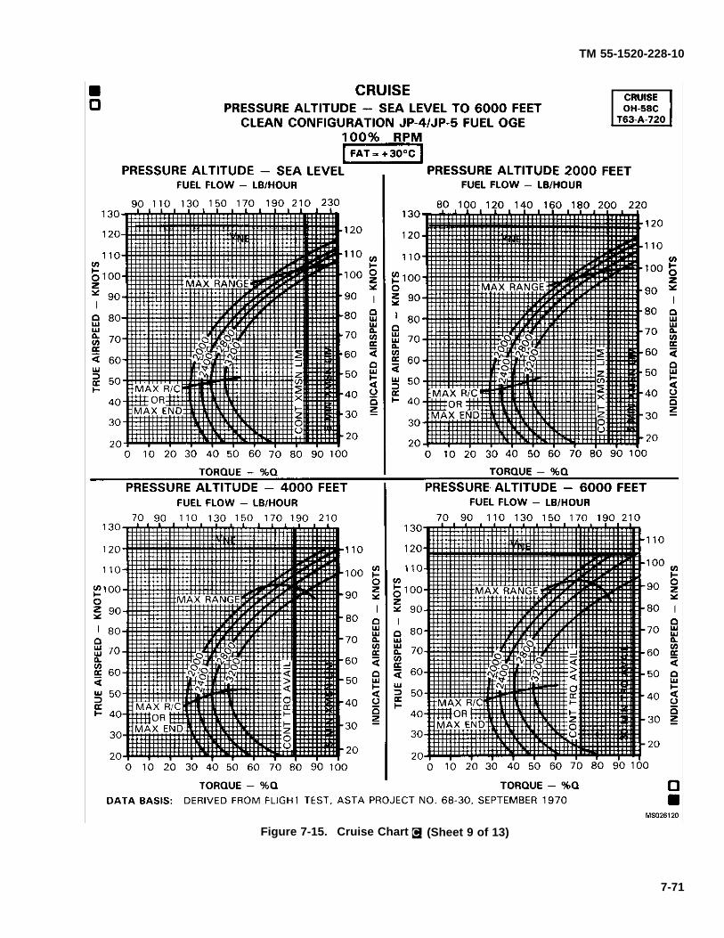
TM 55-1520-228-10
Figure 7-15. Cruise Chart C. (Sheet 9 of 13)
7-71
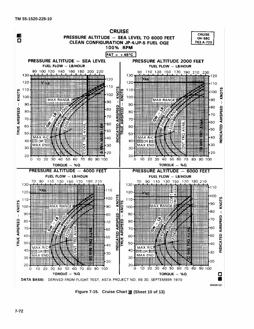
TM 55-1520-228-10
Figure 7-15. Cruise Chart C. (Sheet 10 of 13)
7-72
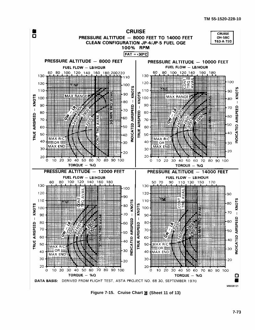
TM 55-1520-228-10
Figure 7-15. Cruise Chart C. (Sheet 11 of 13)
7-73

TM 55-1520-228-10
Figure 7-15. Cruise Chart C. (Sheet 12 of 13)
7-74
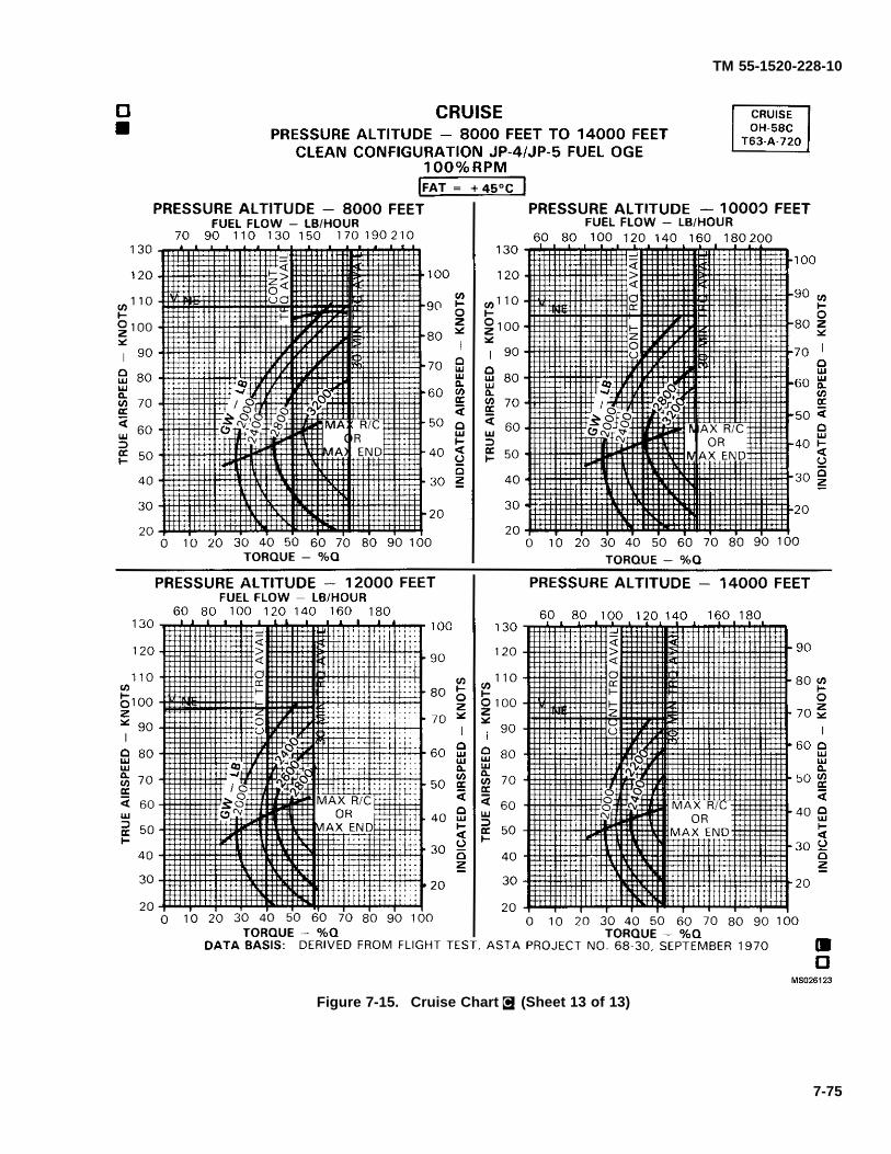
TM 55-1520-228-10
Figure 7-15. Cruise Chart C. (Sheet 13 of 13)
7-75
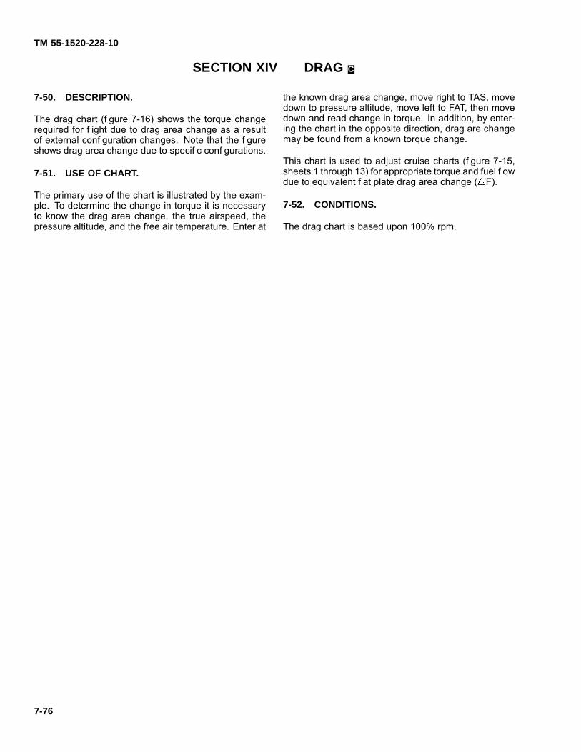
TM 55-1520-228-10
SECTION XIV DRAG C.
7-50. DESCRIPTION.
The drag chart (f gure 7-16) shows the torque changerequired for f ight due to drag area change as a resultof external conf guration changes. Note that the f gureshows drag area change due to specif c conf gurations.
7-51. USE OF CHART.
The primary use of the chart is illustrated by the exam-ple. To determine the change in torque it is necessaryto know the drag area change, the true airspeed, thepressure altitude, and the free air temperature. Enter at
the known drag area change, move right to TAS, movedown to pressure altitude, move left to FAT, then movedown and read change in torque. In addition, by enter-ing the chart in the opposite direction, drag are changemay be found from a known torque change.
This chart is used to adjust cruise charts (f gure 7-15,sheets 1 through 13) for appropriate torque and fuel f owdue to equivalent f at plate drag area change ( F).
7-52. CONDITIONS.
The drag chart is based upon 100% rpm.
7-76
TM 55-1520-228-10
Figure 7-16. Drag Chart
Change 10 7-77
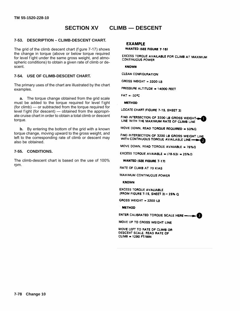
TM 55-1520-228-10
SECTION XV CLIMB — DESCENT
7-53. DESCRIPTION – CLIMB-DESCENT CHART.
The grid of the climb descent chart (f gure 7-17) showsthe change in torque (above or below torque requiredfor level f ight under the same gross weight, and atmo-spheric conditions) to obtain a given rate of climb or de-scent.
7-54. USE OF CLIMB-DESCENT CHART.
The primary uses of the chart are illustrated by the chartexamples.
a. The torque change obtained from the grid scalemust be added to the torque required for level f ight(for climb) — or subtracted from the torque required forlevel f ight (for descent) — obtained from the appropri-ate cruise chart in order to obtain a total climb or descenttorque.
b. By entering the bottom of the grid with a knowntorque change, moving upward to the gross weight, andleft to the corresponding rate of climb or descent mayalso be obtained.
7-55. CONDITIONS.
The climb-descent chart is based on the use of 100%rpm.
7-78 Change 10
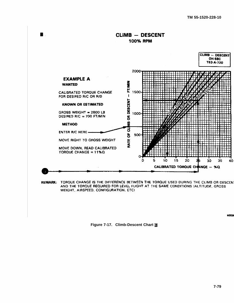
TM 55-1520-228-10
Figure 7-17. Climb-Descent Chart C.
7-79

TM 55-1520-228-10
7-56. DELETED.
7-57. DELETED.
7-58. DELETED.
FIGURE 7-82, FIGURE 7-18 (SHEET 2 OF 2) and 7-83HAVE BEEN DELETED.
7-80 Change 12
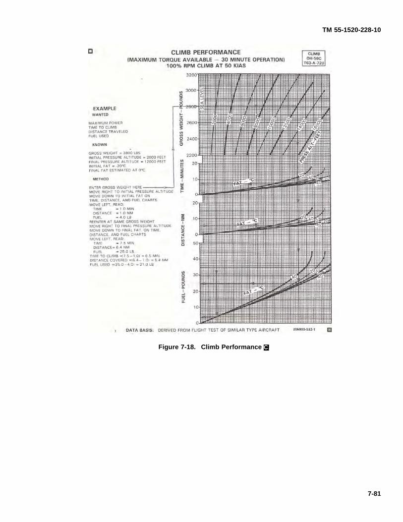
TM 55-1520-228-10
Figure 7-18. Climb Performance C.
7-81
TM 55-1520-228-10
SECTION XVI IDLE FUEL FLOW C.
7-59. DESCRIPTION.
The idle fuel f ow chart (f gure 7-19) shows the fuel f owat f ight idle and at f at pitch with 100% rpm.
7-60. USE OF CHART.
The primary use of the chart is illustrated by the exam-ple. To determine idle f ow, it is necessary to know theidle condition, pressure altitude, and free air tempera-
ture. Enter at the pressure altitude, move right to FAT inappropriate grid, then move down and read fuel f ow onthe scale corresponding to the condition. Refer to thecruise charts to obtain fuel f ow for cruise power condi-tion.
7-61. CONDITIONS.
This chart is based upon the use of JP-4 or JP-5 fueland 100% rpm.
7-82 Change 15
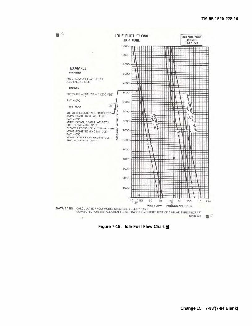
TM 55-1520-228-10
Figure 7-19. Idle Fuel Flow Chart C.
Change 15 7-83/(7-84 Blank)

TM 55-1520-228-10
CHAPTER 8NORMAL PROCEDURES
SECTION I MISSION PLANNING
8-1. MISSION PLANNING.
Mission planning begins when the mission is assignedand extends to the pref ight check of the helicopter. Itincludes, but is not limited to, checks of operating lim-its and restrictions; weight, balance and loading; perfor-mance, publications; f ight plan; and crew and passen-ger brief ngs. The pilot shall ensure compliance with thecontents of this manual which are applicable to the mis-sion.
8-2. AVIATION LIFE SUPPORT EQUIPMENT(ALSE).
All aviation life support equipment required for mission;e. g., helmets, gloves, survival vests, survival kits, etc.,shall be checked.
8-3. CREW DUTIES/RESPONSIBILITIES.
The minimum crew required to f y the helicopter is a pi-lot. During single pilot operations, the pilot shall occupythe right-hand pilot seat. Additional crew members, asrequired, may be added at the discretion of the comman-der. The manner in which each crew member performshis duties is the responsibility of the pilot in command.
a. Crew Brie ng. A crew brief ng shall be con-ducted to ensure a thorough understanding of individualand team responsibilities. The brief ng should include,but not be limited to, copilot, crew chief, mission equip-ment operator, ground crew responsibilities, and thecoordination necessary to complete the mission inthe most eff cient manner. A review of visual signalsis desirable when ground guides do not have voicecommunication with the crew.
b. Passenger Brie ng. The following guide maybe used in accomplishing required passenger brief ngs;items that do not pertain to a specif c mission may beomitted.
(1) Crew introduction.
(2) Equipment.
(a) Personal to include ID tags.
(b) Professional.
(c) Survival.
(3) Flight data.
(a) Route.
(b) Altitude.
(c) Time enroute.
(d) Weather.
(4) Normal procedures.
(a) Entry and exit of helicopter.
(b) Seating.
Demonstrate to passenger how and whereloose carry-on equipment will be secured.Demonstrate to passenger how seat belts andshoulder harnesses are to be used and howthey are to be secured when exiting.
(c) Seat belts.
(d) Movement in the helicopter
8-1
TM 55-1520-228-10
(e) Internal communication.
(f) Security of equipment.
(g) Smoking.
(h) Oxygen.
(i) Refueling.
(j) Weapons.
(k) Protective masks.
(l) Parachutes.
(m) Hearing protection.
(n) Aviation life support equipment (ALSE).
(5) Emergency procedures.
(a) Emergency exits.
(b) Emergency equipment.
(c) Emergency landing/ditching procedures.
(d) Bail out.
(e) Survival.
(f) Recovery.
SECTION II OPERATING PROCEDURES AND MANEUVERS
8-4. OPERATING PROCEDURES ANDMANEUVERS.
This section deals with normal procedures and includesall steps necessary to ensure safe, eff cient operationof the helicopter from the time a pref ight begins untilthe f ight is competed and the helicopter is parked andsecured. Unique feel, characteristics, and reactionof the helicopter during various phases of operationand the techniques and procedures used for taxiing,takeoff, climb, etc., are described, including precautionsto be observed. Your f ying experience is recognized;therefore, basic f ight principles are avoided. Only theduties of the minimum crew necessary for the actualoperation of the helicopter are included. Additionalcrew duties are covered as necessary in Section I.Mission equipment checks are contained in Chapter4. MISSION EQUIPMENT. Procedures specif callyrelated to instrument f ight that are different from normalprocedures are covered in this section, following normalprocedures. Descriptions of functions, operations, andeffects of controls are covered in Section IV, FLIGHTCHARACTERISTICS, and are repeated in this sectiononly when required for emphasis. Checks must beperformed under adverse environmental conditions,such as desert and cold-weather operations, supple-ment normal procedures checks in this section and arecovered in Section V, ADVERSE ENVIRONMENTALCONDITIONS.
8-5. SYMBOLS DEFINITION.
The symbol “O” shall be used to indicate “if installed” theasterisk symbol “*” indicates that performance of step ismandatory for all thru-f ights. The asterisk applies onlyto checks performed prior to takeoff. Placarded itemssuch as switch and control labels appear in capital let-ters.
8-6. CHECKLIST.
Normal procedures are given primarily in checklist form,and amplif ed as necessary in accompanying paragraphform, when a detailed description of a procedure or ma-neuver is required. A condensed version of the amplif edchecklist, omitting all explanatory text, is contained inthe operator’s checklist. To provide for easier cross-ref-erencing, the procedural steps in the condensed check-list are numbered to coincide with the correspondingnumbered steps in this manual.
8-7. PREFLIGHT CHECK.
The pilot walk-around and interior checks are outlinedin the following procedures. the pref ight check is notintended to be a detailed mechanical inspection. Thesteps that are essential for safe helicopter operation areincluded. The pref ight may be made as comprehensiveas conditions warrant at the discretion of the pilot.
8-2 Change 11
TM 55-1520-228-10
8-8. BEFORE EXTERIOR CHECKS.
1. Deleted.
2. Publications — Check DA Forms 2408-12, -3,-14, and -18; DD Form 1896 if required; DD Form 365-4;Compass Cards; locally required forms, records andpublications; and availability of operator’s manual (-10)and checklist (-CL).
*3. Covers, locking devices, tiedowns (except mainrotor), and grounding cables – Removed and secured.
*4. Ignition switch – On.
5. Cockpit – Check as follows:
a. FUEL BOOST switch – OFF.
b. BAT switch – BAT (check fuel quantity).
c. NON-ESS BUS switch – MAN.
d. Lights – Check and set if use is anticipated(LDG, ANTI-COLLISION, POS, CONSOLE, INST, andNVG lights).
e. WARNING and CAUTION lights – Check forillumination of the ROTOR RPM, MASTER CAUTION,ENGINE OUT, and XMSN OIL PRESS lights. Press theWARNING LTS TEST lights. Press the WARNING LTSTEST switch to check XMSN OIL HOT light. Test cau-tion lights and reset. DC GENERATOR, HYD PRESS,and INST INVERTER caution lights should remain illu-minated. Do not f y if any of these lights fail to illuminate.
f. BAT switch – OFF.
g. Pilot seat, seat belt, shoulder harness, andarmor side panels – Check condition.
h. Crew Door – Check condition.
8-9. EXTERIOR CHECK.
8-10. AREA 1 (FIGURE 8-1) – FUSELAGE – CABINRIGHT SIDE.
1. Cabin Interior – Check as follows:
*a. Cargo/loose equipment – Check for properloading and tiedown.
*b. Auxiliary fuel cell – Check condition, fuellevel, and cap secure.
*c. Passenger seats and belts – Check as fol-lows:
(1) Check seat and back cushions for condi-tion and security. Ensure seat belts are through loops onseat and back cushions and secured with nylon safetycord.
(2) Check tabs on top of seat back for condi-tion and security.
(3) Check seat belts and shoulder harnessesfor condition and security. Ensure shoulder harnessesand belts are properly fastened together and tightenedwhen not in use.
(4) If seat belts are not installed, seat andback cushions must be removed prior to f ight with doorsleft off.
d. First aid kit – Check.
Change 11 8-3
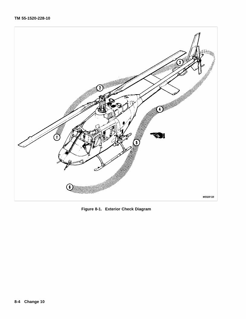
TM 55-1520-228-10
Figure 8-1. Exterior Check Diagram
8-4 Change 10
TM 55-1520-228-10
e. Fire extinguisher – Check.
f. Cabin door – Check condition.
2. Fuselage – Check as following items arechecked.
a. Static port – Check unobstructed.
b. Landing gear – Check condition ofcrosstubes, skid, skid shoe(s), wheels removed.
c. Fuel sample – Check for contamination be-fore f rst f ight of day. If fuel sump has not been drained,drain a sample and check.
*d. Hydraulic reservoir/servos and f ight con-trols – Check condition and oil levels. Hydraulic f lterbutton in. Secure door.
*e. Transmission compartment – Check condi-tion and oil level. Secure door.
f. Engine inlet and plenum – Check clear.
g. Engine compartment – Check condition;lines, cables, and connections for condition and leaks.Secure door.
*h. Fuel – Check quantity f rst f ight of day andwhen refueled. cap secure.
i. FM homing antenna – Check condition.
j. Drain lines and vents – Check unobstructed.
k. Transmission and engine cowling – Checksecure.
l. Engine oil tank – Check condition, cap secure.Close door.
8-11. AREA 2 (FIGURE 8-1) TAILBOOM – RIGHTSIDE.
1. Tailboom – Check as following items arechecked:
a. Driveshaft cover – Check secure.
b. Tail rotor drive – Check shaft, collars, bear-ings, and hangers for condition, slippage marks (if covernot installed).
c. Horizontal stabilizer – Check condition.
d. Vertical f n – Check condition; antenna con-nections secure.
e. Tail skid – Check condition.
*2. Main rotor blade – Check condition, rotate 90degrees to fuselage, tiedown removed.
8-12. AREA 3 (FIGURE 8-1) TAILBOOM – LEFTSIDE.
*1. Tail rotor gearbox – Check condition, oil level,f ller cap, and chip detector wire secure.
*2. Tail rotor – Check condition.
3. Tailboom – Check as following items arechecked:
a. Driveshaft cover – Check secure.
b. Horizontal stabilizer – Check condition.
8-13. AREA 4 (FIGURE 8-1) AFT FUSELAGE –LEFT SIDE.
1. Fuselage – Check as following items arechecked:
a. Oil tank compartment – Check condition of oilcooler, driveshaft, oil lines, and external oil f lter bypass.Secure door.
*b. Engine oil level – Check.
c. Avionics compartment – Check condition ofcompartment and tailboom slippage marks. Securedoor.
d. Engine compartment – Check condition oflines, and connections for security and leaks. Securedoor.
e. FM homing antenna – Check condition
f. Transmission compartment – Check condi-tion. Secure door.
g. Hydraulic servos and f ight controls – Check.
h. External oil f lter bypass – Check.
2. Main rotor blade – Check condition.
Change 14 8-5
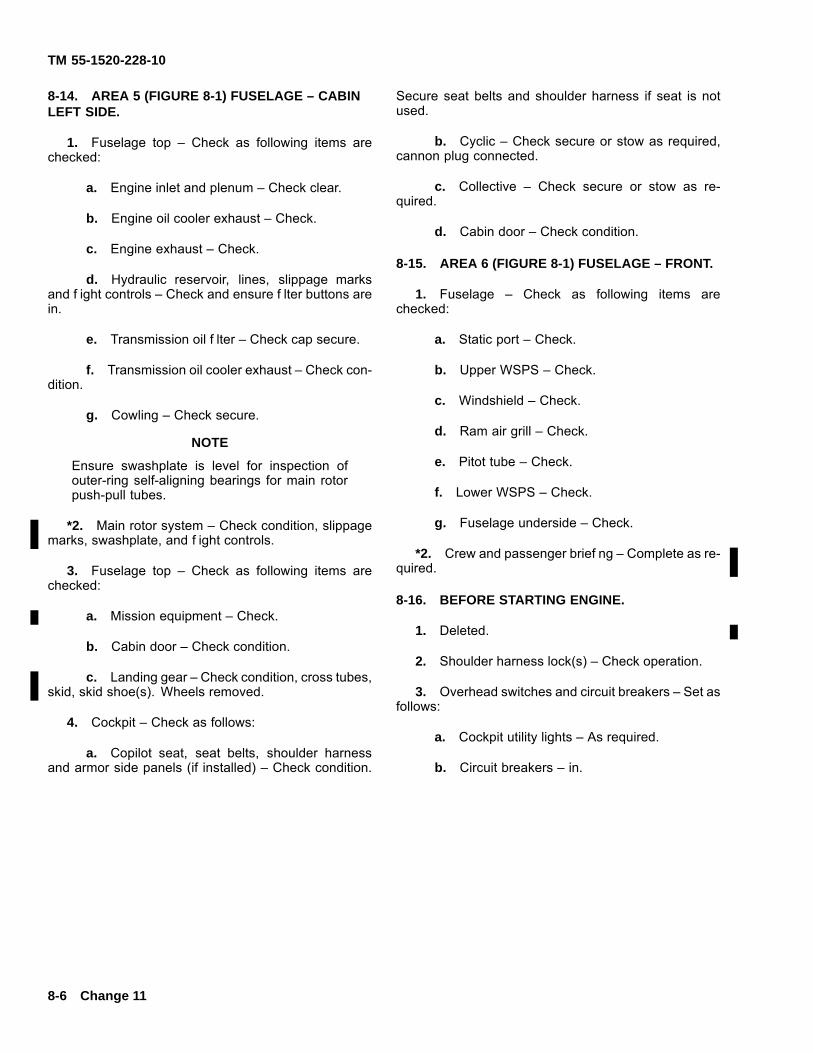
TM 55-1520-228-10
8-14. AREA 5 (FIGURE 8-1) FUSELAGE – CABINLEFT SIDE.
1. Fuselage top – Check as following items arechecked:
a. Engine inlet and plenum – Check clear.
b. Engine oil cooler exhaust – Check.
c. Engine exhaust – Check.
d. Hydraulic reservoir, lines, slippage marksand f ight controls – Check and ensure f lter buttons arein.
e. Transmission oil f lter – Check cap secure.
f. Transmission oil cooler exhaust – Check con-dition.
g. Cowling – Check secure.
NOTE
Ensure swashplate is level for inspection ofouter-ring self-aligning bearings for main rotorpush-pull tubes.
*2. Main rotor system – Check condition, slippagemarks, swashplate, and f ight controls.
3. Fuselage top – Check as following items arechecked:
a. Mission equipment – Check.
b. Cabin door – Check condition.
c. Landing gear – Check condition, cross tubes,skid, skid shoe(s). Wheels removed.
4. Cockpit – Check as follows:
a. Copilot seat, seat belts, shoulder harnessand armor side panels (if installed) – Check condition.
Secure seat belts and shoulder harness if seat is notused.
b. Cyclic – Check secure or stow as required,cannon plug connected.
c. Collective – Check secure or stow as re-quired.
d. Cabin door – Check condition.
8-15. AREA 6 (FIGURE 8-1) FUSELAGE – FRONT.
1. Fuselage – Check as following items arechecked:
a. Static port – Check.
b. Upper WSPS – Check.
c. Windshield – Check.
d. Ram air grill – Check.
e. Pitot tube – Check.
f. Lower WSPS – Check.
g. Fuselage underside – Check.
*2. Crew and passenger brief ng – Complete as re-quired.
8-16. BEFORE STARTING ENGINE.
1. Deleted.
2. Shoulder harness lock(s) – Check operation.
3. Overhead switches and circuit breakers – Set asfollows:
a. Cockpit utility lights – As required.
b. Circuit breakers – in.
8-6 Change 11
TM 55-1520-228-10
c. INST LTS, CONSOLE LTS, and NVG POSLTS — As required.
*d. ANTI-COLLISION LTS switch — As re-quired.
*e. POS LTS switch — As required
f. ENG OIL BYPASS switch — OFF. In a combatsituation with the possibility of oil cooler damage, theswitch should be in AUTO.
g. HTR switch — OFF.
h. DEFOG & VENT switch — OFF.
i. PITOT HTR switch — OFF.
j. ENG DEICE switch — OFF.
k. INV switch — OFF.
l. NON-ESS BUS switch — MAN.
m. GEN switch — OFF.
*n. BAT switch — As required
o. AUX RECP switch — OFF.
p. Fuel Shutoff Valve Handle — Check ON (for-ward and locked).
q. FAT gage — Check.
*4. GPU — Connect for GPU start.
5. Avionics — Off and set.
6. Instrument panel instruments and switches —Check and set as follows:
a. System requirements — Check engine in-struments for static indications, slippage marks andoperating range limit markings.
b. Flight instruments- Check for static indica-tions, set altimeter to f eld elevation, and note settingin Kollsman window.
c. DIR GYRO/MAG switch — As required.
d. FORCE TRIM switch — FORCE TRIM.
e. HYD BOOST switch — HYD BOOST.
*7. Flight controls — Check and set as follows:
a. Control frictions — OFF.
b. Flight controls — Check for full travel; checkengine out/low — rotor audio.
*8. Throttle — Check. Move to open, then to idlestop; press idle release and close.
8-17. STARTING ENGINE.
*1. Fireguard — Post if available.
*2. Rotor blades — Check clear and untied.
*3. Engine — Start as follows:
a. FUEL BOOST switch — FUEL BOOST.
b. STARTER switch — Press and hold.
c. TOT — Check below 200°C.
NOTE
Do not wait for N1 to peak out. Delay in movingthe throttle to engine idle may diminish batterycapacity early in the start cycle.
d. Throttle — Open to engine idle as N1 Accel-erates Through the minimum N1 RPM, as provided be-low.
FAT MINIMUM N1
(a) Above 7°C 15%
(b) –18°C to 7°C 13%
(c) Below –18°C 12%
e. Engine Oil Pressure N1 — Check for in-crease by 20% N1.
f. Main rotor — Check moving by 30% N1.
g. (TOT) Monitor for OVERTEMP conditions.
h. STARTER switch — Release at 58–62% N1.
i. Engine oil pressure — Check.
j. ENGINE OUT and XMSN OIL PRESS warn-ing lights — check out.
Change 14 8-7
TM 55-1520-228-10
k. N1 — 62–64 percent.
Do not have battery switch on and APU systemcharging simultaneously for more than 2 min-utes. This will prevent an unmonitored batteryfrom overheating and possibly exploding.
*4. GPU — Disconnect; then BAT switch — BAT, ifrequired.
*5. N2 — Stabilized.
*6. THROTTLE ADJUST — 70 percent N1.
*7. GEN switch — GEN.
*8. DC amps — Check 60 or less before inverter isturned on.
*9. INV switch — INV.
*10. Avionics — On.
8-18. ENGINE RUNUP.
*1. Engine and transmission instruments — Check.
*2. Throttle — Slowly increase to open. Set N2 to100 percent.
3. HEAT and DEICE systems — Check if use isanticipated as follows, then set as required:
a. ENG DEICE — Check by moving the switchto ENG DEICE; check for rise in TOT; then OFF. TOTshould decrease.
b. PITOT HTR — Check by moving the switchto PITOT HTR; check for an increase in DC AMPS; thenOFF. DC AMPS should decrease.
c. DEFOG & VENT — Check by moving theswitch to DEFOG & VENT; check for an increase in DCAMPS; then OFF. DC amps should decrease.
d. HTR — Check by moving the switch to HTR;Check for increase in TOT; then OFF. TOT should de-crease.
4. Avionics — Check as required.
5. Deleted.
*6. Flight Instruments — Check and set as follows:
a. Attitude indicator — Horizon A. ; Set 5 de-grees above horizon to indicate level attitude at cruisef ight C..
b. Altimeter — Set and check.
(1) Barometric Altimeter — Set to current al-timeter setting and check altitude error.
(2) Radar Altimeter — Test.
c. Heading indicators — Check and set.
*7. Doors, armor side panels and seat belts — Se-cure.
8. Health indicator test (HIT) — Check. Refer toHIT TOT log in the helicopter log book. Perform beforef rst f ight of the day.
*9. Deceleration check. — Perform if required. SeeChapter 5, FUEL OPERATION LIMITS.
a. GEN switch — OFF.
b. N2 RPM — 100 percent. Stabilize 15 sec-onds.
c. Throttle — Idle. Simultaneously start a timecount.
d. Stop as N1 passes through 65 percent.
NOTE
Multiple attempts may be required before prof -ciency is obtained in timing the deceleration.
e. Check deceleration time. Minimum allowabletime is 2 seconds. If deceleration time is less than 2seconds, make two checks to conf rm the time.
8-8 Change 15
TM 55-1520-228-10
f. If deceleration time is less than 2 seconds, air-craft will not be f own. Enter conditions in the “Remarks”section of DA Form 2408-13-1.
g. GEN switch – GEN.
h. Throttle – Slowly increase to open.
8-19. BEFORE TAKEOFF.
Prior to takeoff, the following checks shall be accom-plished:
*1. N2 – 100 percent.
*2. Systems – Check engine, transmission, electri-cal, and fuel systems indications.
*3. Crew, passengers, mission equipment, andseat belts – Check.
*4. Avionics – As required.
8-20. HOVER CHECK.
Perform the following checks at a hover:
*1. Flight controls – Check.
*2. Engine and transmission instruments – Check.
*3. Flight instruments – Check as required.
*4. Power – Check. The power check is performedby comparing the torque required to hover with the pre-dicted values from performance charts.
8-21. TAKEOFF.
During takeoff with the helicopter skids close tothe ground, nose-low attitudes of 10 degrees ormore can result in ground contact of the WSPSlower cutter tip. Forward CG, high gross weight,high density altitude, translational lift settling,and tail wind increases the possibility of groundcontact.
8-22. DELETED.
Change 11 8-9
TM 55-1520-228-10
8-23. BEFORE LANDING.
Prior to landing, the following checks shall be accom-plished:
1. Crew, passenger and mission equipment –Check.
2. Landing light – As required.
8-24. ENGINE SHUTDOWN.
If throttle is inadvertently rolled to close position,do not attempt to roll it back on.
1. Throttle – Engine idle; stabilize TOT for two min-utes.
2. FORCE TRIM switch – FORCE TRIM.
3. FUEL BOOST switch – OFF.
4. NVG/LDG LTS switch – OFF.
5. Control frictions – On.
6. Avionics – Off.
6.1. Deleted.
7. Overhead switches and circuit breakers – Set asfollows:
a. ENG OIL BYPASS switch – OFF.
b. HTR switch – OFF.
c. DEFOG & VENT switch – OFF.
d. PITOT HEAT switch – OFF.
e. ENG DEICE switch – OFF.
f. INV switch – OFf.
8. Battery change – Check as follows:
a. BAT switch – OFF.
b. Ammeter – Check change indication. If thechange in indication is less than 5.0 amperes, the bat-tery is fully charged.
c. BAT switch – BAT.
9. Throttle – Close. TOT, stabilize below 400° C.
10. Overhead switches – OFF as required.
a. GEN.
b. ANTI-COLLISION LTS.
c. POS LTS.
d. CONSOLE LTS, INST LTS, and NVG POSLTS.
e. BAT.
11. Ignition switch – OFF (keys as required).
Do not drop seat belt against side of aircraft.Buckles and bracket will damage honeycombpanel under crew member door frame.
12. Doors – Close immediately after exiting aircraft.
8-25. BEFORE LEAVING THE HELICOPTER.
1. Main rotor blades – Tie down as required.
2. Walk-around – Complete, checking for damage,f uid leaks, and levels.
3. Deleted.
4. DA Forms 2408-12 and 2408-13-1 – Complete.
5. Secure helicopter – As required.
8-10 Change 11
TM 55-1520-228-10
SECTION III INSTRUMENT FLIGHT
8-26. INSTRUMENT FLIGHT – GENERAL.
This aircraft is restricted to visual f ight conditions. Flightinto instrument meteorological conditions will be con-ducted on an emergency basis only. Flight handling,
stability characteristics, and range are the same dur-ing instrument f ight as for visual f ight. Navigation andcommunication equipment are adequate for instrumentf ight.
SECTION IV FLIGHT CHARACTERISTICS
8-27. OPERATING CHARACTERISTICS.
a. The f ight characteristics of this helicopter, ingeneral are similar to other single-rotor helicopters.
b. N2 droop may occur during a normal f ight ma-neuver requiring a rapid increase in power (i.e., rapidcollective and/or tail rotor inputs, high-G maneuvers). IfN2 droop occurs, but low RPM warning is not activatedand N2 recovers to 100 percent within 5 seconds, andfurther droop is not experienced, this is considered anormal f ight characteristic.
8-28. MAST BUMPING.
Mast bumping (f apping-stop contact) is the main yokecontacting the mast and may result in a fractured mastand rotor separation. It may occur during slope landings,rotor startup/coastdown, or when the f ight envelope isexceeded. If bumping occurs during a slope landing,reposition the cyclic to stop the bumping, reestablish ahover, and land on less sloping ground. If bumping oc-curs during startup or shutdown, move cyclic to minimizeor eliminate bumping. If the f ight envelope is inadver-tently exceeded, causing low “G” condition and right roll,move cyclic aft to return rotor to a positive thrust con-dition, then roll level, continuing f ight if mast bumpinghas not occurred. As collective pitch is reduced afterengine failure or loss of tail rotor thrust, cyclic must be
positioned to maintain positive “G” forces during autoro-tation. Touchdown should be accomplished prior to ex-cessive rotor RPM decay. After landing, an entry in DAForm 2408-13-1 is required for appropriate maintenanceinspection.
8-29. SPIKE KNOCK.
a. Spike knock occurs when the round pin in thedrag-pin f tting contacts the side of the square hole ofthe pylon stop, which is mounted to the roof. it createsa loud noise and will occur during a rocking of the pylon.The following factors can cause a spike knock: low rotorRPM, extreme asymmetric loading, poor execution of anautorotational landing and low G maneuvers below +0.5Gs.
b. Spike knock will be more prevalent during zeroground run autorotational landings than for sliding au-torotational landings and running landings.
c. Spike knock in itself is not hazardous but is anindicator of a condition that could be hazardous. if spikeknock is encountered, an entry must be made on DAForm 2408-13-1, to include the f ight conditions underwhich the spike knock has occurred. An inspection willbe performed by maintenance personnel before contin-uing.
Change 14 8-11
TM 55-1520-228-10
d. During landing, starting, and rotor coastdown,spike knock could also occur, especially if there are highwinds and/or the elastomeric damper is deteriorated.This type of spike knock is not considered damaging tothe aircraft.
8-30. PYLON WHIRL.
Pylon whirl is a condition which occurs after blade f ap-ping and mast bumping. The resultant motion of the py-lon is elliptical, and spike knock is apt to occur. If thefrequency of motion coincides with a particular naturalfrequency of the helicopter, and the amplitude and di-rection of the force is large enough, damaging vibrationscan occur in the aft section tailboom of the helicopter.Motion of this type could occur during touchdown au-torotations, if operational limits are exceeded.
8-31. CRITICAL TAILBOOM DYNAMIC MODES.
Two critical tailboom dynamic modes exist. One of thesemay occur during an improperly executed touchdownautorotational landing, and corresponds to a frequencyof less than 64 percent rotor RPM. The second may oc-cur during a high speed autorotational entry, or any ma-neuver in which application of collective allows a signif-icant decay in rotor RPM down to a critical frequencycorresponding to approximately 68-73 percent RPM. Athigh blade angles of attack (increased collective). theremay be a point where the blade does not produce morelift. When there is this condition of low rotor speeds andhigh collective blade angles, there will be excessive f ap-ping of the main rotor. The cycle will be as follows: rotorblade f ap, mast bumping, and spike knock, which willultimately results in main rotor inertia/energy transfer tothe airframe. These conditions generate a resonanceand the tailboom will rapidly respond to these frequen-cies. The tailboom will then have up and down move-ments as it responds to the resonant condition and atsome point, a structural failure will occur. typically, therewill be wrinkles in the tailboom just aft of the boom at-taching points. After the tailboom has buckled and/orbeen damaged, the vibrations may (and usually will)crease; predominantly, because the failure unloads thecondition or the landing has stopped or main rotor f ap-ping has ceased. these could be aggravated by highwinds and abrupt cyclic inputs while in the condition.High forward speed relative to the maneuver may pro-vide the driving force for excessive blade f apping, mastbumping, and as a result, damaging vibration. Likeli-hood of encountering the second mode is remote and isavoidable. if operating limitations of the helicopter areobserved.
8-32. LOSS OF TAIL ROTOR EFFECTIVENESS.
a. Loss of tail rotor effectiveness (LTE) is the oc-currence of an uncommanded and rapid right yaw ratewhich does not subside of its own accord and which,if not quickly reacted to , can result in loss of aircraftcontrol. However, the term “loss of tail rotor effective-ness” is misleading. The tail rotor on this aircraft hasexhibited the capability to produce thrust during all f ightregimes. Under varying combinations of wind azimuthand velocity, tail rotor thrust variations can occur. Whenthis occurs, the helicopter will attempt to yaw to the right.this yaw is usually correctable if immediate additional leftpedal is applied. Correct and timely pilot response to anuncommanded right yaw is critical. If the response is in-correct or slow, the yaw rate may rapidly increase to apoint where recovery may not be possible in the terrainf ight regime.
NOTE
The pilot must anticipate these variations, con-centrate on f ying the aircraft, and not allow ayaw rate to build.
b. Extensive f ight testing and wind-tunnel testshave identif ed three relative wind azimuth and velocityregions as capable of adversely affecting aircraft con-trollability and dramatically increasing pilot workload.For illustration, specif c wind azimuths and velocities areidentif ed for each region (see f gure 8-2). However, thepilot must realize the boundaries of these regions mayshift in azimuth or velocity depending on the ambientconditions.
(1) Weathercock stability (120-140 degrees).Winds within this region will attempt to weathervane theaircraft into the relative wind. The helicopter exhibitsa tendency to make a slow uncommanded yaw toeither the left or right, depending upon the exact winddirection. Due to the inherent yaw characteristics ofthis helicopter, the right yaw rate will increase unlessarrested by the pilot. A right yaw can develop into anLTE condition and requires immediate correction.
(2) Vortex ring state (210-330 degrees). Windswithin this region will cause a vortex rind state to de-velop around the tail rotor, which, in turn, causes tailrotor thrust variations. The helicopter exhibits a ten-dency to make uncommanded pitch, roll, and yaw excur-sions. The subsequent aircraft reactions require multi-ple pedal, cyclic, and collective inputs by the pilot. main-taining a precise heading in this region will be impossi-ble. Pilot workload in this region will be high; therefore,the pilot must concentrate fully on f ying the aircraft andnot allow a right yaw rate to build.
8-12 Change 14
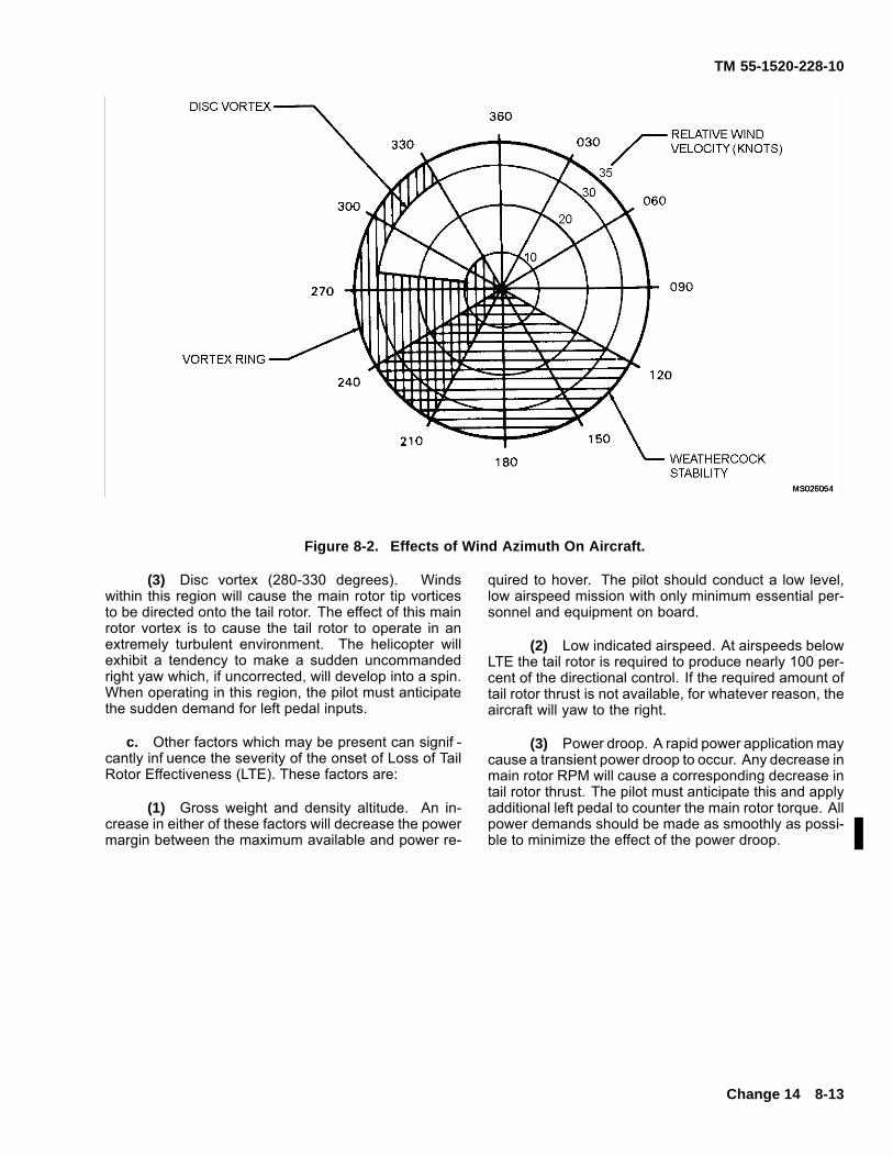
TM 55-1520-228-10
Figure 8-2. Effects of Wind Azimuth On Aircraft.
(3) Disc vortex (280-330 degrees). Windswithin this region will cause the main rotor tip vorticesto be directed onto the tail rotor. The effect of this mainrotor vortex is to cause the tail rotor to operate in anextremely turbulent environment. The helicopter willexhibit a tendency to make a sudden uncommandedright yaw which, if uncorrected, will develop into a spin.When operating in this region, the pilot must anticipatethe sudden demand for left pedal inputs.
c. Other factors which may be present can signif -cantly inf uence the severity of the onset of Loss of TailRotor Effectiveness (LTE). These factors are:
(1) Gross weight and density altitude. An in-crease in either of these factors will decrease the powermargin between the maximum available and power re-
quired to hover. The pilot should conduct a low level,low airspeed mission with only minimum essential per-sonnel and equipment on board.
(2) Low indicated airspeed. At airspeeds belowLTE the tail rotor is required to produce nearly 100 per-cent of the directional control. If the required amount oftail rotor thrust is not available, for whatever reason, theaircraft will yaw to the right.
(3) Power droop. A rapid power application maycause a transient power droop to occur. Any decrease inmain rotor RPM will cause a corresponding decrease intail rotor thrust. The pilot must anticipate this and applyadditional left pedal to counter the main rotor torque. Allpower demands should be made as smoothly as possi-ble to minimize the effect of the power droop.
Change 14 8-13
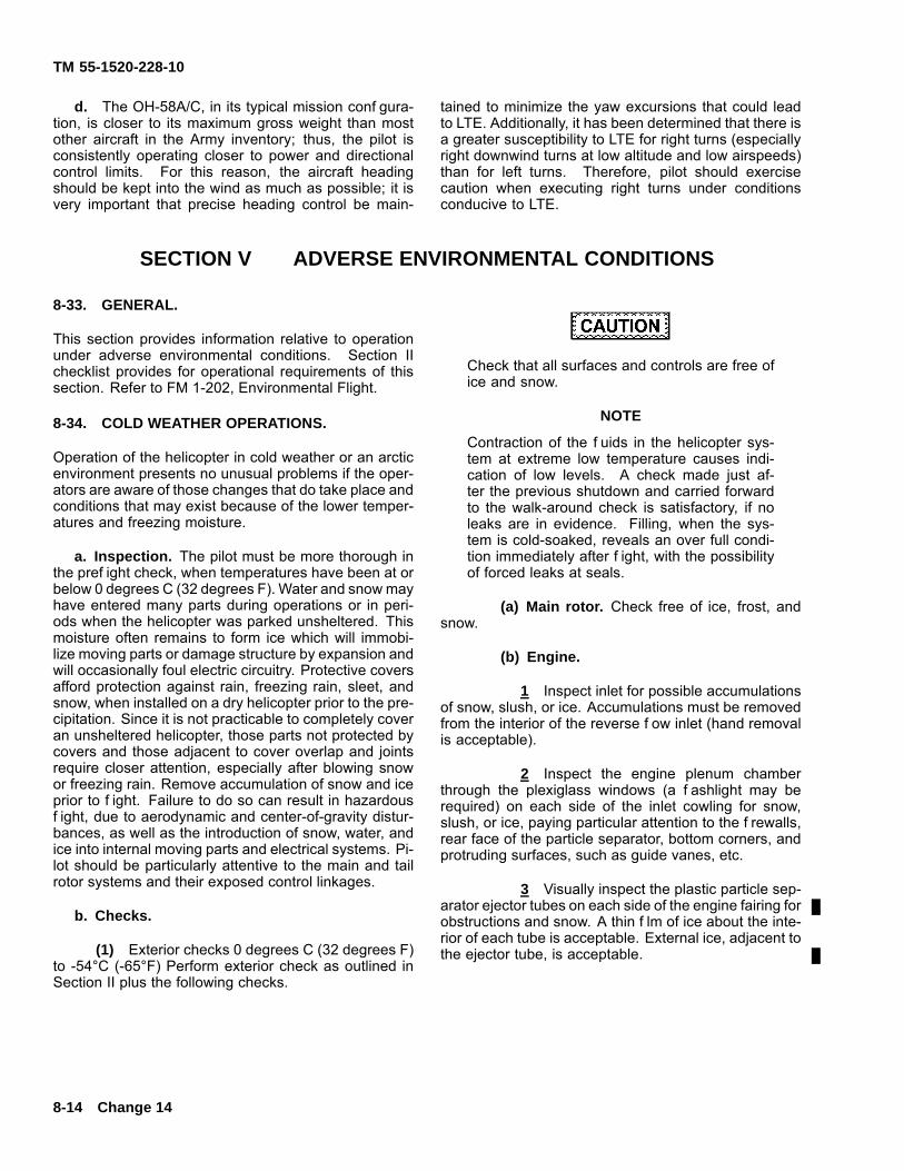
TM 55-1520-228-10
d. The OH-58A/C, in its typical mission conf gura-tion, is closer to its maximum gross weight than mostother aircraft in the Army inventory; thus, the pilot isconsistently operating closer to power and directionalcontrol limits. For this reason, the aircraft headingshould be kept into the wind as much as possible; it isvery important that precise heading control be main-
tained to minimize the yaw excursions that could leadto LTE. Additionally, it has been determined that there isa greater susceptibility to LTE for right turns (especiallyright downwind turns at low altitude and low airspeeds)than for left turns. Therefore, pilot should exercisecaution when executing right turns under conditionsconducive to LTE.
SECTION V ADVERSE ENVIRONMENTAL CONDITIONS
8-33. GENERAL.
This section provides information relative to operationunder adverse environmental conditions. Section IIchecklist provides for operational requirements of thissection. Refer to FM 1-202, Environmental Flight.
8-34. COLD WEATHER OPERATIONS.
Operation of the helicopter in cold weather or an arcticenvironment presents no unusual problems if the oper-ators are aware of those changes that do take place andconditions that may exist because of the lower temper-atures and freezing moisture.
a. Inspection. The pilot must be more thorough inthe pref ight check, when temperatures have been at orbelow 0 degrees C (32 degrees F). Water and snow mayhave entered many parts during operations or in peri-ods when the helicopter was parked unsheltered. Thismoisture often remains to form ice which will immobi-lize moving parts or damage structure by expansion andwill occasionally foul electric circuitry. Protective coversafford protection against rain, freezing rain, sleet, andsnow, when installed on a dry helicopter prior to the pre-cipitation. Since it is not practicable to completely coveran unsheltered helicopter, those parts not protected bycovers and those adjacent to cover overlap and jointsrequire closer attention, especially after blowing snowor freezing rain. Remove accumulation of snow and iceprior to f ight. Failure to do so can result in hazardousf ight, due to aerodynamic and center-of-gravity distur-bances, as well as the introduction of snow, water, andice into internal moving parts and electrical systems. Pi-lot should be particularly attentive to the main and tailrotor systems and their exposed control linkages.
b. Checks.
(1) Exterior checks 0 degrees C (32 degrees F)to -54°C (-65°F) Perform exterior check as outlined inSection II plus the following checks.
Check that all surfaces and controls are free ofice and snow.
NOTE
Contraction of the f uids in the helicopter sys-tem at extreme low temperature causes indi-cation of low levels. A check made just af-ter the previous shutdown and carried forwardto the walk-around check is satisfactory, if noleaks are in evidence. Filling, when the sys-tem is cold-soaked, reveals an over full condi-tion immediately after f ight, with the possibilityof forced leaks at seals.
(a) Main rotor. Check free of ice, frost, andsnow.
(b) Engine.
1 Inspect inlet for possible accumulationsof snow, slush, or ice. Accumulations must be removedfrom the interior of the reverse f ow inlet (hand removalis acceptable).
2 Inspect the engine plenum chamberthrough the plexiglass windows (a f ashlight may berequired) on each side of the inlet cowling for snow,slush, or ice, paying particular attention to the f rewalls,rear face of the particle separator, bottom corners, andprotruding surfaces, such as guide vanes, etc.
3 Visually inspect the plastic particle sep-arator ejector tubes on each side of the engine fairing forobstructions and snow. A thin f lm of ice about the inte-rior of each tube is acceptable. External ice, adjacent tothe ejector tube, is acceptable.
8-14 Change 14
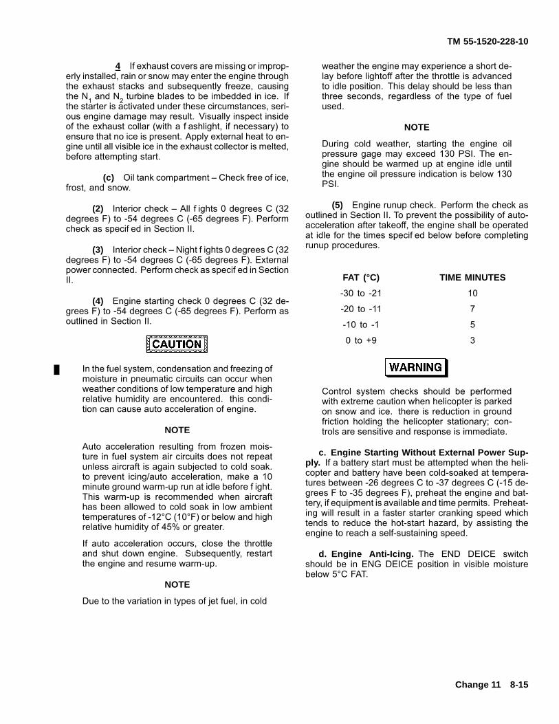
TM 55-1520-228-10
4 If exhaust covers are missing or improp-erly installed, rain or snow may enter the engine throughthe exhaust stacks and subsequently freeze, causingthe N1 and N2 turbine blades to be imbedded in ice. Ifthe starter is activated under these circumstances, seri-ous engine damage may result. Visually inspect insideof the exhaust collar (with a f ashlight, if necessary) toensure that no ice is present. Apply external heat to en-gine until all visible ice in the exhaust collector is melted,before attempting start.
(c) Oil tank compartment – Check free of ice,frost, and snow.
(2) Interior check – All f ights 0 degrees C (32degrees F) to -54 degrees C (-65 degrees F). Performcheck as specif ed in Section II.
(3) Interior check – Night f ights 0 degrees C (32degrees F) to -54 degrees C (-65 degrees F). Externalpower connected. Perform check as specif ed in SectionII.
(4) Engine starting check 0 degrees C (32 de-grees F) to -54 degrees C (-65 degrees F). Perform asoutlined in Section II.
In the fuel system, condensation and freezing ofmoisture in pneumatic circuits can occur whenweather conditions of low temperature and highrelative humidity are encountered. this condi-tion can cause auto acceleration of engine.
NOTE
Auto acceleration resulting from frozen mois-ture in fuel system air circuits does not repeatunless aircraft is again subjected to cold soak.to prevent icing/auto acceleration, make a 10minute ground warm-up run at idle before f ight.This warm-up is recommended when aircrafthas been allowed to cold soak in low ambienttemperatures of -12°C (10°F) or below and highrelative humidity of 45% or greater.
If auto acceleration occurs, close the throttleand shut down engine. Subsequently, restartthe engine and resume warm-up.
NOTE
Due to the variation in types of jet fuel, in cold
weather the engine may experience a short de-lay before lightoff after the throttle is advancedto idle position. This delay should be less thanthree seconds, regardless of the type of fuelused.
NOTE
During cold weather, starting the engine oilpressure gage may exceed 130 PSI. The en-gine should be warmed up at engine idle untilthe engine oil pressure indication is below 130PSI.
(5) Engine runup check. Perform the check asoutlined in Section II. To prevent the possibility of auto-acceleration after takeoff, the engine shall be operatedat idle for the times specif ed below before completingrunup procedures.
FAT (°C) TIME MINUTES
-30 to -21 10
-20 to -11 7
-10 to -1 5
0 to +9 3
Control system checks should be performedwith extreme caution when helicopter is parkedon snow and ice. there is reduction in groundfriction holding the helicopter stationary; con-trols are sensitive and response is immediate.
c. Engine Starting Without External Power Sup-ply. If a battery start must be attempted when the heli-copter and battery have been cold-soaked at tempera-tures between -26 degrees C to -37 degrees C (-15 de-grees F to -35 degrees F), preheat the engine and bat-tery, if equipment is available and time permits. Preheat-ing will result in a faster starter cranking speed whichtends to reduce the hot-start hazard, by assisting theengine to reach a self-sustaining speed.
d. Engine Anti-Icing. The END DEICE switchshould be in ENG DEICE position in visible moisturebelow 5°C FAT.
Change 11 8-15
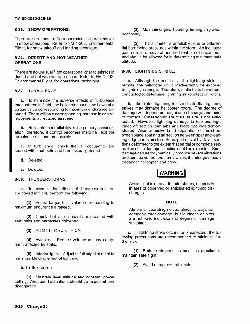
TM 55-1520-228-10
8-35. SNOW OPERATIONS.
There are no unusual f ight operational characteristicsin snow operations. Refer to FM 1-202, EnvironmentalFlight, for snow takeoff and landing technique.
8-36. DESERT AND HOT WEATHEROPERATIONS.
There are no unusual f ight operational characteristics indesert and hot weather operations. Refer to FM 1-202,Environmental Flight, for operational technique.
8-37. TURBULENCE.
a. To minimize the adverse effects of turbulenceencountered in f ight, the helicopter should be f own at atorque value corresponding to maximum endurance air-speed. There will be a corresponding increase in controlmovements at reduced airspeed.
b. Helicopter controllability is the primary consider-ation; therefore, if control becomes marginal, exit theturbulence as soon as possible.
c. In turbulence, check that all occupants areseated with seat belts and harnesses tightened.
d. Deleted.
e. Deleted.
8-38. THUNDERSTORMS.
a. To minimize the effects of thunderstorms en-countered in f ight, perform the following:
(1) Adjust torque to a value corresponding tomaximum endurance airspeed.
(2) Check that all occupants are seated withseat belts and harnesses tightened.
(3) PITOT HTR switch – ON.
(4) Avionics – Reduce volume on any equip-ment affected by static.
(5) Interior lights – Adjust to full bright at night tominimize blinding effect of lightning
b. In the storm:
(1) Maintain level altitude and constant powersetting. Airspeed f uctuations should be expected anddisregarded.
(2) Maintain original heading, turning only whennecessary.
(3) The altimeter is unreliable, due to differen-tial barometric pressures within the storm. An indicatedgain or loss of several hundred feet is not uncommonand should be allowed for in determining minimum safealtitude.
8-39. LIGHTNING STRIKE.
a. Although the possibility of a lightning strike isremote, the helicopter could inadvertently be exposedto lightning damage. Therefore, static tests have beenconducted to determine lightning strike effect on rotors.
b. Simulated lightning tests indicate that lightningstrikes may damage helicopter rotors. The degree ofdamage will depend on magnitude of charge and pointof contact. Catastrophic structural failure is not antic-ipated. However, lightning damage to hub bearings,blade aft section, trim tabs and blade tips was demon-strated. Also, adhesive bond separation occurred be-tween blade spar and aft section between spar and lead-ing edge abrasion strip. Some portions of blade aft sec-tions deformed to the extent that partial or complete sep-aration of the damaged section could be expected. Suchdamage can aerodynamically produce severs vibrationsand serious control problems which, if prolonged, couldendanger helicopter and crew.
Avoid f ight in or near thunderstorms, especiallyin area of observed or anticipated lightning dis-charges.
NOTE
Abnormal operating noises almost always ac-company rotor damage, but loudness or pitchare not valid indications of degree of damagesustained.
c. If lightning strike occurs, or is expected, the fol-lowing precautions are recommended to minimize fur-ther risk:
(1) Reduce airspeed as much as practical tomaintain safe f ight.
(2) Avoid abrupt control inputs.
8-16 Change 10
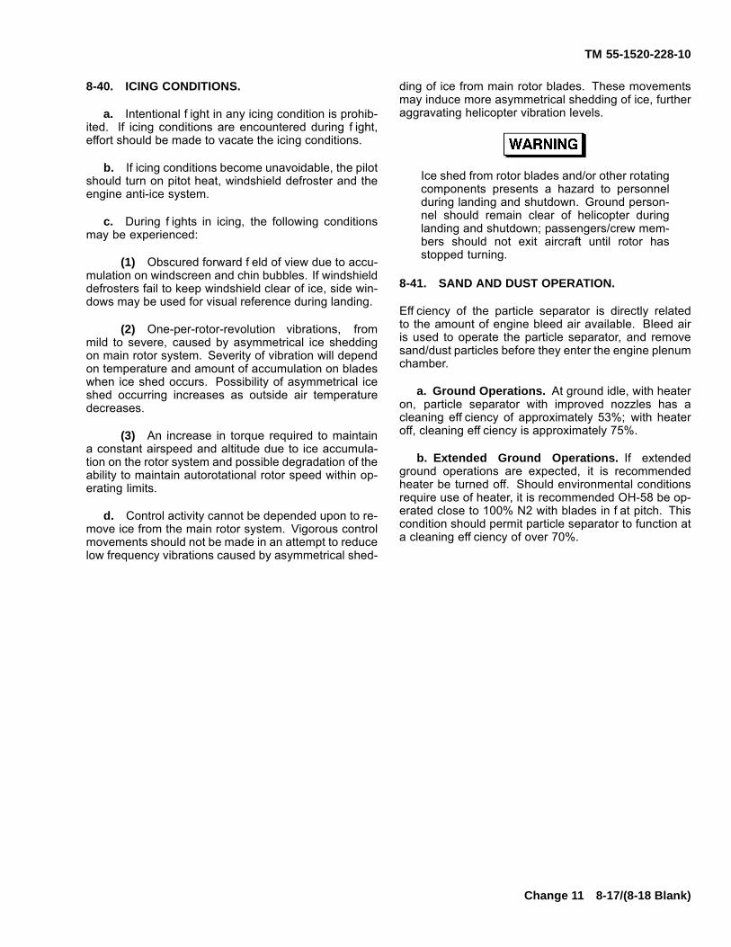
TM 55-1520-228-10
8-40. ICING CONDITIONS.
a. Intentional f ight in any icing condition is prohib-ited. If icing conditions are encountered during f ight,effort should be made to vacate the icing conditions.
b. If icing conditions become unavoidable, the pilotshould turn on pitot heat, windshield defroster and theengine anti-ice system.
c. During f ights in icing, the following conditionsmay be experienced:
(1) Obscured forward f eld of view due to accu-mulation on windscreen and chin bubbles. If windshielddefrosters fail to keep windshield clear of ice, side win-dows may be used for visual reference during landing.
(2) One-per-rotor-revolution vibrations, frommild to severe, caused by asymmetrical ice sheddingon main rotor system. Severity of vibration will dependon temperature and amount of accumulation on bladeswhen ice shed occurs. Possibility of asymmetrical iceshed occurring increases as outside air temperaturedecreases.
(3) An increase in torque required to maintaina constant airspeed and altitude due to ice accumula-tion on the rotor system and possible degradation of theability to maintain autorotational rotor speed within op-erating limits.
d. Control activity cannot be depended upon to re-move ice from the main rotor system. Vigorous controlmovements should not be made in an attempt to reducelow frequency vibrations caused by asymmetrical shed-
ding of ice from main rotor blades. These movementsmay induce more asymmetrical shedding of ice, furtheraggravating helicopter vibration levels.
Ice shed from rotor blades and/or other rotatingcomponents presents a hazard to personnelduring landing and shutdown. Ground person-nel should remain clear of helicopter duringlanding and shutdown; passengers/crew mem-bers should not exit aircraft until rotor hasstopped turning.
8-41. SAND AND DUST OPERATION.
Eff ciency of the particle separator is directly relatedto the amount of engine bleed air available. Bleed airis used to operate the particle separator, and removesand/dust particles before they enter the engine plenumchamber.
a. Ground Operations. At ground idle, with heateron, particle separator with improved nozzles has acleaning eff ciency of approximately 53%; with heateroff, cleaning eff ciency is approximately 75%.
b. Extended Ground Operations. If extendedground operations are expected, it is recommendedheater be turned off. Should environmental conditionsrequire use of heater, it is recommended OH-58 be op-erated close to 100% N2 with blades in f at pitch. Thiscondition should permit particle separator to function ata cleaning eff ciency of over 70%.
Change 11 8-17/(8-18 Blank)

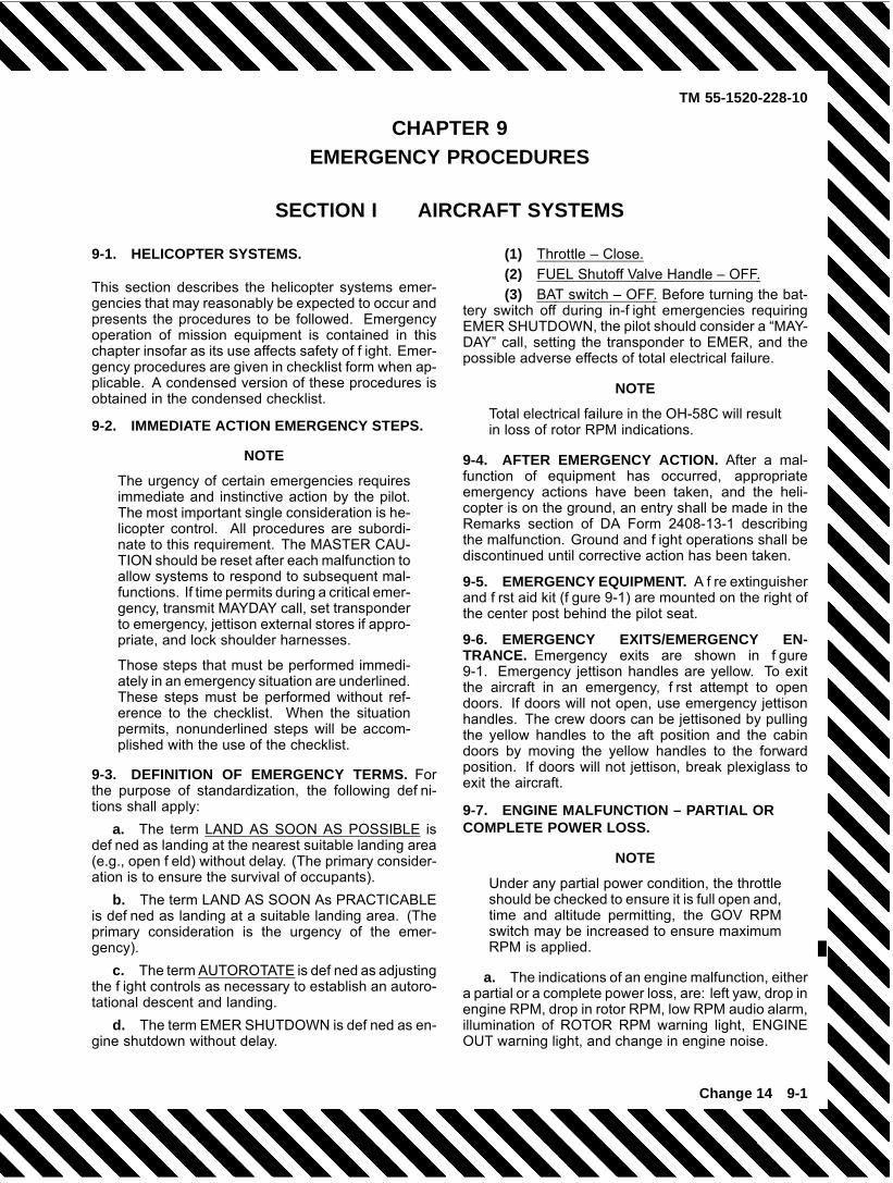
TM 55-1520-228-10
CHAPTER 9EMERGENCY PROCEDURES
SECTION I AIRCRAFT SYSTEMS
9-1. HELICOPTER SYSTEMS.
This section describes the helicopter systems emer-gencies that may reasonably be expected to occur andpresents the procedures to be followed. Emergencyoperation of mission equipment is contained in thischapter insofar as its use affects safety of f ight. Emer-gency procedures are given in checklist form when ap-plicable. A condensed version of these procedures isobtained in the condensed checklist.
9-2. IMMEDIATE ACTION EMERGENCY STEPS.
NOTE
The urgency of certain emergencies requiresimmediate and instinctive action by the pilot.The most important single consideration is he-licopter control. All procedures are subordi-nate to this requirement. The MASTER CAU-TION should be reset after each malfunction toallow systems to respond to subsequent mal-functions. If time permits during a critical emer-gency, transmit MAYDAY call, set transponderto emergency, jettison external stores if appro-priate, and lock shoulder harnesses.
Those steps that must be performed immedi-ately in an emergency situation are underlined.These steps must be performed without ref-erence to the checklist. When the situationpermits, nonunderlined steps will be accom-plished with the use of the checklist.
9-3. DEFINITION OF EMERGENCY TERMS. Forthe purpose of standardization, the following def ni-tions shall apply:
a. The term LAND AS SOON AS POSSIBLE isdef ned as landing at the nearest suitable landing area(e.g., open f eld) without delay. (The primary consider-ation is to ensure the survival of occupants).
b. The term LAND AS SOON As PRACTICABLEis def ned as landing at a suitable landing area. (Theprimary consideration is the urgency of the emer-gency).
c. The term AUTOROTATE is def ned as adjustingthe f ight controls as necessary to establish an autoro-tational descent and landing.
d. The term EMER SHUTDOWN is def ned as en-gine shutdown without delay.
(1) Throttle – Close.(2) FUEL Shutoff Valve Handle – OFF.(3) BAT switch – OFF. Before turning the bat-
tery switch off during in-f ight emergencies requiringEMER SHUTDOWN, the pilot should consider a “MAY-DAY” call, setting the transponder to EMER, and thepossible adverse effects of total electrical failure.
NOTE
Total electrical failure in the OH-58C will resultin loss of rotor RPM indications.
9-4. AFTER EMERGENCY ACTION. After a mal-function of equipment has occurred, appropriateemergency actions have been taken, and the heli-copter is on the ground, an entry shall be made in theRemarks section of DA Form 2408-13-1 describingthe malfunction. Ground and f ight operations shall bediscontinued until corrective action has been taken.
9-5. EMERGENCY EQUIPMENT. A f re extinguisherand f rst aid kit (f gure 9-1) are mounted on the right ofthe center post behind the pilot seat.
9-6. EMERGENCY EXITS/EMERGENCY EN-TRANCE. Emergency exits are shown in f gure9-1. Emergency jettison handles are yellow. To exitthe aircraft in an emergency, f rst attempt to opendoors. If doors will not open, use emergency jettisonhandles. The crew doors can be jettisoned by pullingthe yellow handles to the aft position and the cabindoors by moving the yellow handles to the forwardposition. If doors will not jettison, break plexiglass toexit the aircraft.
9-7. ENGINE MALFUNCTION – PARTIAL ORCOMPLETE POWER LOSS.
NOTE
Under any partial power condition, the throttleshould be checked to ensure it is full open and,time and altitude permitting, the GOV RPMswitch may be increased to ensure maximumRPM is applied.
a. The indications of an engine malfunction, eithera partial or a complete power loss, are: left yaw, drop inengine RPM, drop in rotor RPM, low RPM audio alarm,illumination of ROTOR RPM warning light, ENGINEOUT warning light, and change in engine noise.
Change 14 9-1
TM 55-1520-228-10
Do not respond to the RPM audio and/or warn-ing light illumination without f rst conf rming en-gine malfunction by one or more of the otherindications. Normal indications signify that theengine is functioning properly and that there isa tachometer generator failure or an open cir-cuit to the warning system, rather than an ac-tual engine malfunction.
b. Flight Characteristics.
(1) Control response with an engine inopera-tive is similar to a descent with power.
(2) Airspeed above the minimum rate of de-scent from autorotational glide characteristics chart(f gure 9-2) will result in greater rates of descent butmay be used as necessary to extend glide distance.
(3) Airspeeds below minimum rate of descentairspeeds will increase rate of descent and decreaseglide distance.
(4) Should the engine malfunction during a leftbank maneuver , right cyclic input to level the aircraftmust be made simultaneously with collective pitch ad-justment. If the collective pitch is decreased without acorresponding right cyclic input, the helicopter will pitchdown and roll rate will increase rapidly, resulting in asignif cant loss of altitude.
c. Partial Power Condition. Under partial powerconditions, the engine may operate smoothly at re-duced power or it may operate erratically with intermit-tent surges of power. In instances where a power loss
is experienced without accompanying power surging,the helicopter may be f own at reduced power to a suit-able landing area. under this condition, the pilot shouldalways be prepared for a complete power loss. In theevent a partial power condition is accompanied by er-ratic engine operation or power surging, and f ight isto be continued, the throttle may be adjusted in an at-tempt to correct the surging condition. if f ight is notpossible, close the throttle completely and complete anautorotational landing.
d. Complete Power Loss. Under a completepower loss condition, delay in recognition of themalfunction, improper technique or excessive ma-neuvering to reach a suitable landing area reducesthe probability of a safe autorotational landing. Flightconducted within the avoid area of the chart (f gure )exposes the helicopter to a high probability of damagedespite the best efforts of the pilot.
e. Low Airspeed and Low Altitude. Under low al-titude low airspeed conditions, the deceleration capa-bility is limited, and caution should be used to avoidstriking the ground with the tail rotor. Initial collectivereduction will vary after an engine malfunction, depen-dent upon the altitude and airspeed at the time of theoccurrence. For example, collective should not be de-creased when an engine failure occurs at a hover be-low 15 feet; whereas, during cruise f ight conditions,altitude and airspeed are suff cient for a signif cant re-duction in collective, thereby, allowing rotor RPM to bemaintained in the safe operating range during autoro-tational descent. the rotor may overspeed and requirecollective pitch application to maintain the RPM belowthe upper limit. Collective should never be applied toreduce RPM below normal limits for extending glidedistance because of the reduction in RPM available foruse during autorotational landing.
9-2 Change 14
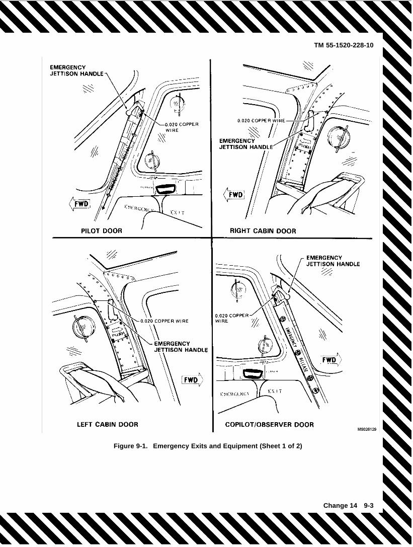
TM 55-1520-228-10
Figure 9-1. Emergency Exits and Equipment (Sheet 1 of 2)
Change 14 9-3
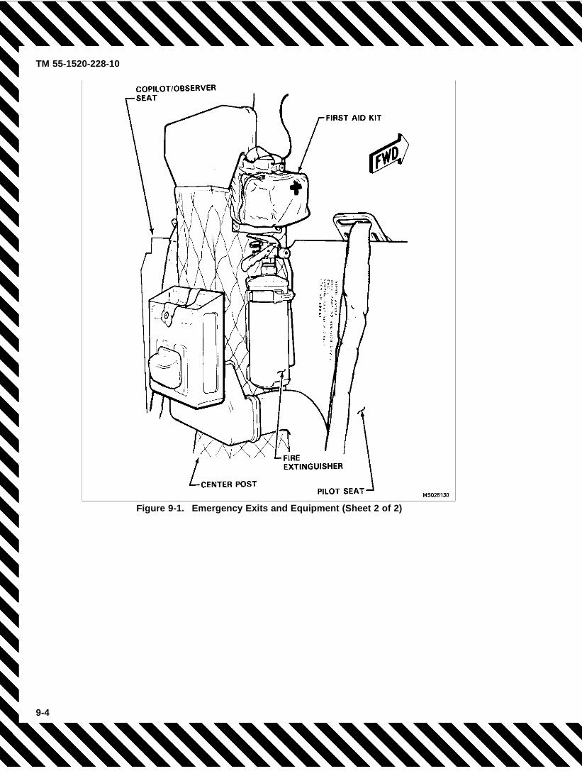
TM 55-1520-228-10
Figure 9-1. Emergency Exits and Equipment (Sheet 2 of 2)
9-4
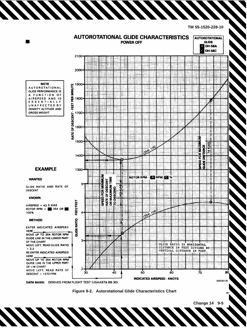
TM 55-1520-228-10
Figure 9-2. Autorotational Glide Characteristics Chart
Change 14 9-5
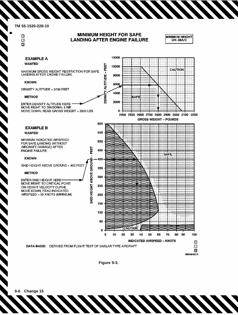
TM 55-1520-228-10
Figure 9-3.
9-6 Change 15
TM 55-1520-228-10
9-8. MINIMUM RATE OF DESCENT – POWEROFF. ��� ������ �� ���� ���� � ����� � �� ����� �� �� � � ������� �������� � �� � ��� � � ��������� ���� ���� �� ����� � ! ����������� �" �"������������������ ������9-9. MAXIMUM GLIDE DISTANCE – POWEROFF. ��� ��#���� �"��� ����� �� �� ����� �� �� � � ������� �������� � $� � ��� �� $� � ��� � � ��������� ���� ���� �� figure � �� ��#���� �"�������� ���9-10. ENGINE FAILURE – HOVER.
%&�'�'�%�(�9-11. ENGINE FAILURE – LOWERALTITUDE/LOWAIRSPEED OR CRUISE.
�� %&�'�'�%�(� � (�(� )*&�+',-� %�����"��� ���� � ��
��� � � ���� ��������9-12. ENGINE RESTART – DURING FLIGHT. %���� � �� � ��"��� � flight, � � �� � ����� ��. /� ���������� 0������ ��� �#��� ����� � ��� � �� � ��"��� �� �� /� ������� �� � flight, ��� ������� �� ������� ��� ����� ��"" ���� � � ��� �"������ � � �����1��"�/"�! ���� � ����� �! ���� ���" "� �� � �����! � ����� ������� �� �1��"�/"�� & ��� ����" �� ����� �! �����#�����". � � �� ��� �� ��2����� �� ����� �������flight ��� ��� ���� ��� ��������� ����� �� /��� � 3 ���������� �� ���� �� ������� � � flight ������
�� ������"� 4 5"���� � %������ �������� 6%-+ %) )''- %) �'))306(�
9-13. ENGINE COMPRESSOR STALL. ( �� ����������� ���"" ��. /� ����������7�� /. � ����� ���/"� �� � ������ � "��� �������! ��1��� � �� � 1�/����� � � � ����� ���� � �'� ���� �� � � ��� ��1����. ���� ������ %��� � �� � ���������� ���""! �� ��1�����2���� � ����� �� ��#���� ����� ���"������ � ����"�/� �1������ )���"� � �� � ���������� ���"" �����8
�� 5�""����1� 4 ������� � (-9 +(35( � � *�� �������� 4 '::��� 6%-+ %) )''- %) �'))306(�
9-14. ENGINEOVERSPEED. ( �� � �1������� ��""/� � ������� /. � ����� .��! ����� � ������ � /��� ������ � � �� � ���! � � � � ������ � � �� � � � ����� ����� 3 � � �� � �1������� �� �#����� ���8
�� 5�""����1� 4 3 ������ �� "��� ��� ����� � ������� � �� �;����� ��� /�"�� ��� ��#���� ������� � "�����
� ������"� 4 %�<��� � ��" ����" - ������� ���� �� ����� ���
�� 6%-+ %) )''- %) �'))306(� ������ ������� �������� � � "� �� � /. �� ���""� ���� ��� �� ��"". ���� ������"��
a. 3 ��� �� �� /� �� ���""�� �� ��"".8�� %&�'�'�%�(��� �1�� � ��� "� �� �
���� ���"� ����"�� ����". �"��� � ��� �����"�
� (�(� )*&�+',-� %�����"��� ���� ������ � � ���� ��������
9-15. ENGINE UNDERSPEED.a. 3 � � �� � � �������� ������! ��� ��""��
��1� ���� /� ��<����� ��� ���� �� ��� ��� ����� �������� "������ 3 ������� flight���� ����� � ��� ���� �� /� ������"�����! 6%-+ %) )''- %) �'))306( � � ���� ���� ��"" ������ � �� � "� �� ��b. % � �� � � �������� /�"�� ��� - ����"��
� ����� ��� ����. /�"�� �� ���� ��� "������ )���"����� �����8
�� %&�'�'�%�(� � (�(� )*&�+',-� %�����"��� ���� �
����� �! � ���� ��������9-16. ENGINE SURGES. 3 ������ � � �� � ������ �#����� ���8
�� 9'= ��� ������ 4 3-5� �� ��#���� ���� � ������"� 4 %�<��� �� �>� - ��� 6%-+ %) )''- %) �'))306(�
3 � �� � ������ ��� �� �� ���""�� � ����� � � � �/�1�! ������� �� �""���8
� %&�'�'�%�( 4 ,�� �1�� ��� "� �� ������
?� (�(� )*&�+',-� %�����"��� ���� � ����� � � ���� ��������
9-16.1. LOW ENGINE OIL PRESSURE AND LOSSOF TORQUE INDICATION. 3 ��� � �� � ��" ���������� �������� � �� � ������� 7��� ���� ������� .� � "���� ���2�� � ����"��� "��� � � �� � ����� �� �����/"��
�� 6%-+ %) )''- %) �'))306(�
)���"� � �� � ��" �������� ���� �� 7��� ��� ��� ��" ����������� � ������� � ����� �� /� 1�"���9-17. ROTORS, TRANSMISSION AND DRIVESYSTEMS MALFUNCTIONS.9-18. TAIL ROTOR FAILURE AND DIRECTIONALCONTROL MALFUNCTIONS. 0������ � ��� �� .����� � ��"� ���� � ���� �� �����! �� �� �� �����/"��� ���1��� � ��"���� �� �1��. ������ �.� ��� ������� � ���� � ���� ��� ������ �. ���� �� � 2����� �".��� � ��� �� ����� � � ��"����� � ��� ������������ �. ���������� ��� �""��� � �� � ��������� � ���� �.��� � ��"� ���� �! ���/�/"� �����! � ���������1� ����� ��
Change 17 9-7
TM 55-1520-228-10
9-19. COMPLETE LOSS OF TAIL ROTORTHRUST. ���� �������� � 1�"1�� � /���� � ��� ���1��.����! ���� �� � ��1���� ���1�����! ����� � ��� ���"����� �� "��� ������a. Powered Flight.(1) Indications:(a) %/ ����" 1�/����� ��(b) ����" � ��� ��� � ���� � ��"�������
�����(c) -��� � ��� ��"������� ��� � �� ��� �����
@"�� �"����"��A�(d) 6�� ��"" � ��� ���"��� �"� � ��� "� ��
���� �" �#���
+����� � ��"" � � �"����"�� ��. /� 1����� /.1��.� � ������"� � �;�� ��""����1� @%� ���������/�"�� �� � ��� � ������� �����! ��� �"����"����. /����� � �� ���""�/"�! � � ��� ��"������� ��"" /��� �� ��� � ��� 1������" �#���%���������� ��. /� ��� � ". ����� A�(2) Procedures:(a) 5� �� �� ������� flight, � �����/"�! ��
� �����/"� "� �� � ���� �� �� �/�1� �� ���� ���� ������ � ���������
(b) %&�'�'�%�( ��� "� �� � ���� ����������
1 3 � �� � "� �� � �� �����/"�! ����"��� ����������� ���� � �������� �������� �� ��2����� �� �������� �" �� ���"�
2 3 � �� � "� �� � �� �� �����/"�! ������� ����"����� ��� �/��� $? ��� �"������! �� ���� ������ ���� � ����� �� �� � �� ���� ��� ��� ��"������� ������� �� �� � ���� (#����� �������� ����� ����� ��""����1� ��"" <��� ����� �� �������� � � "�1�"�������� ���� �� ���� ���� � ������b. +�"�����
9-20. FIXED PITCH SETTINGS. ���� �� � ��"� ���� � 1�"1� � � "��� � �� ���" ����"�� � � � fixed ���������� �� ,������ ��� ��� � ��� ��"������� .��� "�� ������� �� ���� �� � ��� ��� ���� � � ����" ���"��� ����� ���� � ��� ��"� ���� � ������"��� � ����" ���
�� � �� ��� ���� � ��"� ���� ! � 1��.� � ���� � � ���"����� ������ ��"" /� ��"�1���� �� �"" ����� ���� � flight.
a. Reduced power (low torque).(1) 3 ������� �8 ��� ��� � ��� ��"������� ��""
��� ����� ��� ����� �� ���"����(2) Procedure:(a) 3 ��"������� �� ���" �� /� ��� ��� �� �
������� flight, ��� /��� ��"���� �� �� ��� ��� �� ���"���� ����� � � ������"��� � �� � "� �� � �� ��� �� ��������/"��
(b) 3 ��"������� �� ���" �� �� /� ��� ��� ��! �"��� ��� ������"� ���������". � � ������"���� ����������� �" "� �� ��
b. Increased power (high torque).(1) Indications: ��� ��� � ��� ��"������� ��""
��� "�� ��� ��� ����� �� �������(2) Procedure:(a) ��� ��� �� ���" ���� ����� � � ���
������ @0����� �� � � $� � ����A(b) 3 �����! ������ � �� � ��� �� ��"".
�� �>��(c) 5� �� �� ������� flight �� � �����/"�
"� �� � ���� ����� �� � "� �� � �� /� ������"������
(d) (#����� � �� � "� �� � ���� ������ � � �������� ����� ����� ��"" �� ���7� �����"������ ������"� � � ��""����1�! �� �������.! �� �� ���"�����"�� � � ����� ��c. Hover.(1) Indication: *�"������� ����� � �� �� /�
�� ���""�� ���� ����"��(2) Procedure.(a) :�#�� ����" 4 6� ��(b) 6��� � ���" ����� ������ 4 ������ ��1��
� � ����������� �
9-21. LOSS OF TAIL ROTOR COMPONENTS. �����1����. � ���� �������� �� ���� �� � ��� ��� ���� �� ������ "���� % . "��� � ���� ����� ��"" ����"� � ������� �� ��� � ���1��. ����! ��2���� � �� �.�"���a. Indications:
9-8 Change 17 PIN: 014142-017
TM 55-1520-228-10
(1) Varying degrees of right yaw depending onpower applied and airspeed at time of failure.
(2) Forward CG shift.
b. Procedure:
(1) Enter autorotative descent (power off).
(2) Maintain airspeed above minimum rate ofdescent airspeed.
(3) If run-on landing is possible, complete au-torotation with a touchdown airspeed above effectivetranslational lift.
(4) If run-on landing is not possible, start todecelerate from about 75 feet altitude, so that forwardgroundspeed is at a minimum when the helicopterreaches 10 to 20 feet; execute the touchdown with arapid collective pull just prior to touchdown in a levelattitude with minimum ground run.
9-22. LOSS OF TAIL ROTOR EFFECTIVENESS(LTE). This is a situation involving a loss of effectivetail rotor thrust without a break in the drive systemwhich cannot be stopped with full left pedal application.If LTE is experienced, simultaneously:
1. Pedal – Full Left.
2. Cyclic – Forward.
3. As recovery is effected, adjust controls fornormal f ight.
Collective reduction will aid in arresting theyaw rate; however, if a rate of descent hasbeen established, collective reduction mayincrease the rate of descent to an excessivevalue. The resultant large and rapid increasein collective to prevent ground or obstaclecontact may further increase the yaw rate,decrease the rotor RPM and cause an over-torque and/or over-temperature condition.Therefore, the decision to reduce collectivemust be based on the pilot assessment of thealtitude available for recovery.
If spin cannot be stopped and crash is imminent, anautorotation may be the best course of action. Main-
tain full left pedal until the spin stops, then adjust tomaintain heading.
9-23. MAIN DRIVESHAFT FAILURE. A failure of themain driveshaft will be indicatedby a sudden increasein engine RPM, decrease in rotor RPM, left yaw andactivation of the low RPM audio, and illumination of theROTOR RPM warning light. A transient overspeed ofN1 and N2 may occur but will stabilize. In the event ofmain driveshaft failure:
1. AUTOROTATE – Establish a power-on au-torotational glide. The engine must continueto operate at normal operating RPM in orderto provide tail rotor control.
2. EMER SHUTDOWN after landing.
9-24. CLUTCH FAILS TO DISENGAGE. A clutchfailing to disengage in f ight will be indicated by therotor RPM decaying with engine RPM as the throttleis reduced to the engine idle position when enteringautorotational descent. This condition results in totalloss of autorotational capability. If a failure occurs:
1. Throtle – Open.
2. LAND AS SOON AS POSSIBLE.
9-25. MAST BUMPING.
LAND AS SOON AS POSSIBLE.
a.
9-26. FIRE. The safety of helicopter occupants is theprimary consideration when f re occurs; therefore, it isimperative that every effort be made by the f ight crewto put the f re out. On the ground, it is essential that theengine be shut down, crew and passengers evacuatedand f re f ghting begun immediately. If time permits, a“MAYDAY” radio call should be made before the electri-cal power is off to expedite assistance from f re f ghtingequipment and personnel. If the helicopter is airbornewhen a f re occurs, the most important single actionthat can be taken by the pilot is to land the helicopter.
Toxic fumes of the extinguishing agent maycause injury, and liquid agent may cause frost-bite or low temperature burns.
Change 14 9-9
TM 55-1520-228-10
If aircraft f re occurs on ground while usingGround Power Unit (GPU); the GPU should beshutdown immediately.
9-27. HOT START.
During engine starts using a Ground PowerUnit (GPU), failure of the GPU could possiblyresult in an engine hot start. After GPU fail-ure during start, the pilot must turn the batteryswitch on before accomplishing the proceduredescribed below.
During engine starting or shutdown, if TOT limits areexceeded, or it becomes apparent that TOT limits maybe exceeded.
1. Starter switch – Continue to press and holduntil TOT is less than 200°C.
2. Throttle – Close.
9-28. ENGINE/FUSELAGE/ELECTRICAL FIRE –GROUND.
EMER SHUTDOWN.
a.9-29. ENGINE/FUSELAGE FIRE – IN FLIGHT. If af re is observed during f ight, prevailing circumstancessuch as VMC, IMC, night, altitude, and landing areasavailable must be considered in order to determinewhether to execute a power-on, or power-off landing.
a. If Power-On landing:1. LAND AS SOON AS POSSIBLE.2. EMER SHUTDOWN after landing.
b. If Power-Off landing:1. AUTOROTATE.2. EMER SHUTDOWN. Accomplish during
descent if time permits.9-30. ELECTRICAL FIRE – FLIGHT. Prior to shut-ting off all electrical power, the pilot must consider theequipment that is essential to a particular f ight environ-ment that will be encountered. In the event of electricalf re or suspected electrical f re in f ight:
1. BAT and GEN switches – OFF.2. LAND AS SOON AS POSSIBLE.3. EMER SHUTDOWN after landing.
30.1. DELETED.
9-31. SMOKE AND FUME ELIMINATION. Smokeand/or toxic fumes entering the cockpit and cabin canbe exhausted as follows:
Do not jettison doors in f ight above effectivetranslational lift.
1. Vents – Open.2. DEFOG and VENT switch – ON.
9-32. ELECTRICAL SYSTEM MALFUNCTIONS.9-33. GENERATOR FAILURE – NO OUTPUT. Ano-output malfunction of the generator will be indicatedby a zero indication on the DC AMMETER and a DCGENERATOR caution light illumination. An attemptmay be made to put the generator back on line byaccomplishing the following:
1. GEN FIELD and GEN & BUS RESET circuitbreakers – Check in.
2. GEN switch – RESET then GEN – Do not holdthe switch in the RESET position.
If the generator is not restored, or if it goes off lineagain:
3. GEN switch – OFF.4. Turn OFF all unnecessary electrical equip-
ment.5. LAND AS SOON AS PRACTICABLE.
9-34. OVERHEATED BATTERY. An abnormallyhigh DC AMMETER indication is evidence of a highbattery charging rate or a battery thermal runaway.High battery charging amperage is normal immediatelyafter engine start and should dissipate within minutes.DC AMMETER indications of 30 AMPS or below isnormal after 15 minutes of aircraft operation with allsystems operating.
Do not open battery compartment or attemptto disconnect or remove overheated battery.Battery f uid will cause burns and overheatedbattery will cause thermal burns and may ex-plode.
If high DC amperage does not dissipate:1. BAT switch – OFF.If high DC amperage indication disappears with
BAT switch OFF, a high battery charging rateand possible battery thermal runaway is con-f rmed, in this event:
9-10 Change 14
TM 55-1520-228-10
2. LAND AS SOON AS POSSIBLE.3. EMER SHUTDOWN after landing.If high DC amperage indication does not dissipate,
pilot should anticipate electrical f re in f ight.
9-35. HYDRAULIC SYSTEM MALFUNCTION.
9-36. HYDRAULIC POWER FAILURE. Hydraulicpower failure will be evident when the force requiredfor control movement increases; a moderate feedbackin the cyclic and collective controls is felt and the HYDPRESS caution light illuminates. Control movementswill result in normal aircraft response in every respect.In the event of hydraulic power failure:
1. Airspeed – Adjust as necessary to attain themost comfortable level of control movements.
2. HYD BOOST SOL circuit breaker – Out;check for restoration of hydraulic power.
If hydraulic power is not restored:3. HYD BOOST SOL circuit breaker – In.4. HYD BOOST switch – OFF.
Do not return the HYD BOOST switch to theON position for the remainder of the f ight. Thisprevents any possibility of a surge in hydraulicpressure and the resulting loss of control.
5. LAND AS SOON AS PRACTICABLE at anarea that will permit a run-on landing.
9-37. LANDING AND DITCHING.
9-38. LANDING IN TREES. A landing in treesshould be made when no other landing area is avail-able. In addition to accomplishing engine malfunctionemergency procedures, select a landing area con-taining the least number of trees of minimum height.Decelerate to minimum forward speed at treetop leveland descend into the trees vertically. Apply all theremaining collective, prior to the main rotor bladesentering the trees.
9-39. DITCHING – POWER ON. If ditching becomesnecessary, with power available accomplish an ap-proach to a hover above the water and:
1. Doors – Jettison at a hover.2. Crew (except pilot) and passengers – Exit.3. Hover a safe distance away form personnel.4. AUTOROTATE. Apply all remaining collective
as the helicopter enters the water. Maintain alevel attitude as the helicopter sinks and untilit begins to roll, then apply cyclic in directionof the roll.
5. Pilot – Exit when the main rotor stops.
9-40. DITCHING – POWER OFF. If an engine failureoccurs over water and ditching is imminent, accomplishengine failure emergency procedures and proceed asfollows:
1. AUTOROTATE. Decelerate to minimum for-ward speed as the helicopter nears the wa-ter. Apply all remaining collective as the heli-copter enters the water. Maintain a level atti-tude as the helicopter sinks and until it beginsto roll, then apply cyclic in the direction of theroll.
2. Doors – Jettison.3. Crew and passengers – Exit when the main
rotor stops.
9-41. FLIGHT CONTROL MALFUNC-TIONS. Failure of components within the f ightcontrol system may be indicated through varyingdegrees of feedback, binding, resistance, or sloppi-ness. These conditions should not be mistaken forhydraulic power failure. In the event of a f ight controlmalfunction:
1. LAND AS SOON AS POSSIBLE.2. EMER SHUTDOWN after landing.
9-42. LIGHTNING STRIKE.1. LAND AS SOON AS POSSIBLE.
a.
9-43. IN-FLIGHT WIRE STRIKE.1. LAND AS SOON AS POSSIBLE.
a.
Change 14 9-11

TM 55-1520-228-10
SECTION II MISSION EQUIPMENT.
NOT APPLICABLE
9-12 Change 14

Table 9-1. Warning/Caution Panel Lights
WARNING LIGHT CORRECTIVE ACTION
ROTOR RPM (Red) Verify condition. Adjust collective.
MASTER CAUTION Check for Caution Panel segment light illumination. Ifnone, LAND AS SOON AS POSSIBLE.
ENGINE OUT (Red) Verify condition. AUTOROTATE.
XMSN OIL PRESS (Red) LAND AS SOON AS POSSIBLE.
XMSN OIL HOT (Red) LAND AS SOON AS POSSIBLE.
CAUTION LIGHT CORRECTIVE ACTION
FUEL BOOST LAND AS SOON AS PRACTICABLE
20 MIN FUEL LAND AS SOON AS PRACTICABLE
FUEL FILTER LAND AS SOON AS POSSIBLE.
ENG OIL BYPASS LAND AS SOON AS POSSIBLE.
ENG CHIP DET LAND AS SOON AS POSSIBLE.
XMSN CHIP DET LAND AS SOON AS POSSIBLE.
T/R CHIP DET LAND AS SOON AS POSSIBLE.
INST INVERTER Information/system status
DC GENERATOR Refer to emergency procedures
HYD PRESS Refer to emergency procedures
IFF Information/system status
SPARE LAND AS SOON AS POSSIBLE.
Change 14 9-13/(9-14 Blank)
TM 55-1520-228-10

TM 55-1520-228-10
APPENDIX AREFERENCES
The following documents of the issue in effect on date of invitation for bids are required for use by overhaul mainte-nance personnel in performance of their duties and form a part of this Technical Manual (TM). Other specif cationsmay be required as specif ed in these documents. Those specif cations are not listed in this appendix.
AR 70-50 . . . . . . . . . . . . . . . . . . . . . . . . . . . . Designating and Naming Defense Military Aerospace Vehicles
AR 95-1 . . . . . . . . . . . . . . . . . . . . . . . . . . . . . Army Aviation General Provisions and Flight Regulations
AR 385-40 . . . . . . . . . . . . . . . . . . . . . . . . . . . Accident Reporting and Records
DA Form 2408-13 . . . . . . . . . . . . . . . . . . . . Aircraft Status Information Record
DA Form 2408-13-1 . . . . . . . . . . . . . . . . . . . Aircraft Inspection and Maintenance Record
DA PAM 738-751 . . . . . . . . . . . . . . . . . . . . . Functional Users Manual for the Army Maintenance Management Sys-tem — Aviation (TAMMS-A)
FM 1-202 . . . . . . . . . . . . . . . . . . . . . . . . . . . . Environmental Flight
FM 1-203 . . . . . . . . . . . . . . . . . . . . . . . . . . . . Fundamentals Of Flight
FM 10-67-1 . . . . . . . . . . . . . . . . . . . . . . . . . . Concepts And Equipment Of Petroleum Operations
FM 10-68 . . . . . . . . . . . . . . . . . . . . . . . . . . . . Aircraft Refueling
MIL-STD-12 . . . . . . . . . . . . . . . . . . . . . . . . . . Abbreviations For Use On Drawing and in Specif cations, Standards andTechnical Documents
MWO 1-1520-228-50-48 . . . . . . . . . . . . . . Installation of Airframe Mounted Fuel Filter Assembly
MWO 1-1520-228-50-52 . . . . . . . . . . . . . . Installation of Altitude Voice Warning System
MWO 1-1520-228-50-53 . . . . . . . . . . . . . . Global Positioning System (GPS)
MWO 55-1520-228-30-30 . . . . . . . . . . . . . Modif cation of OH-58 A/C Passenger Seat Cushions Installation
MWO 55-1520-228-50-24 . . . . . . . . . . . . . Installation of Altimeter, AAU-31/AAU-32A in OH-58A Helicopter
MWO 55-1520-228-50-44 . . . . . . . . . . . . . Installation of External Scavenger Oil Filter Kit
TM 1-1500-250-23-1 . . . . . . . . . . . . . . . . . . General Tie-Down and Mooring on All Series Army Models AH-64,UH-60, CH-47, UH-1, AH-1, and OH-58 Helicopters
TM 11-5810-262-OP . . . . . . . . . . . . . . . . . . Operating Procedures for Cryptographic Speech EquipmentTSEC/KY-58
TM 11-5841-284-23&P . . . . . . . . . . . . . . . . Operator Organizational and Direct Support Maintenance Manual (in-cluding Repair Parts and Special Tools List Altimeter Set, Electronic,AN/APN-209(V) 1 and AN/APN209(V) 2.
TM 11-5841-294-12 . . . . . . . . . . . . . . . . . . . Operator and Aviation Unit Maintenance Manual for Radar Signal De-tecting Set An/APR-39A(V)1
TM 38-250 . . . . . . . . . . . . . . . . . . . . . . . . . . . Preparation of Hazardous Materials for Military Air Shipment
TM 55-1500-342-23 . . . . . . . . . . . . . . . . . . . Army Aviation Maintenance Engineering Manual — Weight and Balance
TM 750-244-1-5 . . . . . . . . . . . . . . . . . . . . . . Procedure for the Destruction of Aircraft and Associated Equipment toPrevent Enemy Use
Change 15 A-1/(A-2 Blank)


TM 55-1520-228-10
APPENDIX BDEPOT MOBILIZATION REQUIREMENT
B-1. DEPOT MOBILIZATION REQUIREMENTS. Under a state of mobilization, the procuring activity may electto:
a. Eliminate the minor repair stipulation in the preshop analysis section of the DMWR. This will require all itemsto be overhauled, maximizing the longevity of such items but requiring full turnaround time during depot mainte-nance.
b. Extend the operating hour ceiling, which is currently stipulated in the preshop analysis section, for accom-plishing minor repair. This will assure a quicker turnaround during depot maintenance but will not maximize longevity.
B-1/B-2 Blank

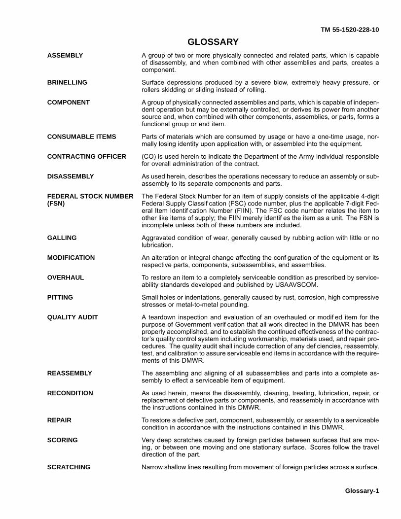
TM 55-1520-228-10
GLOSSARYASSEMBLY A group of two or more physically connected and related parts, which is capable
of disassembly, and when combined with other assemblies and parts, creates acomponent.
BRINELLING Surface depressions produced by a severe blow, extremely heavy pressure, orrollers skidding or sliding instead of rolling.
COMPONENT A group of physically connected assemblies and parts, which is capable of indepen-dent operation but may be externally controlled, or derives its power from anothersource and, when combined with other components, assemblies, or parts, forms afunctional group or end item.
CONSUMABLE ITEMS Parts of materials which are consumed by usage or have a one-time usage, nor-mally losing identity upon application with, or assembled into the equipment.
CONTRACTING OFFICER (CO) is used herein to indicate the Department of the Army individual responsiblefor overall administration of the contract.
DISASSEMBLY As used herein, describes the operations necessary to reduce an assembly or sub-assembly to its separate components and parts.
FEDERAL STOCK NUMBER(FSN)
The Federal Stock Number for an item of supply consists of the applicable 4-digitFederal Supply Classif cation (FSC) code number, plus the applicable 7-digit Fed-eral Item Identif cation Number (FIIN). The FSC code number relates the item toother like items of supply; the FIIN merely identif es the item as a unit. The FSN isincomplete unless both of these numbers are included.
GALLING Aggravated condition of wear, generally caused by rubbing action with little or nolubrication.
MODIFICATION An alteration or integral change affecting the conf guration of the equipment or itsrespective parts, components, subassemblies, and assemblies.
OVERHAUL To restore an item to a completely serviceable condition as prescribed by service-ability standards developed and published by USAAVSCOM.
PITTING Small holes or indentations, generally caused by rust, corrosion, high compressivestresses or metal-to-metal pounding.
QUALITY AUDIT A teardown inspection and evaluation of an overhauled or modif ed item for thepurpose of Government verif cation that all work directed in the DMWR has beenproperly accomplished, and to establish the continued effectiveness of the contrac-tor’s quality control system including workmanship, materials used, and repair pro-cedures. The quality audit shall include correction of any def ciencies, reassembly,test, and calibration to assure serviceable end items in accordance with the require-ments of this DMWR.
REASSEMBLY The assembling and aligning of all subassemblies and parts into a complete as-sembly to effect a serviceable item of equipment.
RECONDITION As used herein, means the disassembly, cleaning, treating, lubrication, repair, orreplacement of defective parts or components, and reassembly in accordance withthe instructions contained in this DMWR.
REPAIR To restore a defective part, component, subassembly, or assembly to a serviceablecondition in accordance with the instructions contained in this DMWR.
SCORING Very deep scratches caused by foreign particles between surfaces that are mov-ing, or between one moving and one stationary surface. Scores follow the traveldirection of the part.
SCRATCHING Narrow shallow lines resulting from movement of foreign particles across a surface.
Glossary-1

TM 55-1520-228-10
SERVICING The lubrication, treating, cleaning, or preservation necessary to maintain the equip-ment and other respective parts in serviceable condition.
SPALLING Chipped or f aked surface caused by the breaking away of the hardened surfacelayer of the metal. A surface fatigue condition which occurs from the underminingof the case hardened metal and separation of the case from the core.
TEST As used herein, is the testing of equipment using shop test equipment to determinethat the unit functions properly within the limits set forth in this DMWR.
USAAVSCOM — US Army Aviation Systems Command.
Glossary-2 Change 15

TM 55-1520-228-10
INDEX
ParagraphFigure, Table
Subject Number
A
AAU-31 / A PNEUMATIC ALTIMETER. . . . . . . . . . . . . . . . . . . . . . . . . . . . . . . . . . . . . . . . . . . . . . . . . . . . . . . . . . . . . . . . . . 2-62Description. . . . . . . . . . . . . . . . . . . . . . . . . . . . . . . . . . . . . . . . . . . . . . . . . . . . . . . . . . . . . . . . . . . . . . . . . . . . . . . . . . . . . . . 2-62.1Operation . . . . . . . . . . . . . . . . . . . . . . . . . . . . . . . . . . . . . . . . . . . . . . . . . . . . . . . . . . . . . . . . . . . . . . . . . . . . . . . . . . . . . . . . 2-62.2
Abnormal Operation. . . . . . . . . . . . . . . . . . . . . . . . . . . . . . . . . . . . . . . . . . . . . . . . . . . . . . . . . . . . . . . . . . . . . . . . . . 2-62.2.bNormal Operation. . . . . . . . . . . . . . . . . . . . . . . . . . . . . . . . . . . . . . . . . . . . . . . . . . . . . . . . . . . . . . . . . . . . . . . . . . . . 2-62.2.a
ABBREVIATIONS. . . . . . . . . . . . . . . . . . . . . . . . . . . . . . . . . . . . . . . . . . . . . . . . . . . . . . . . . . . . . . . . . . . . . . . . . . . . . . . . . . . . . . 1-6AEROBATIC MANEUVERS. . . . . . . . . . . . . . . . . . . . . . . . . . . . . . . . . . . . . . . . . . . . . . . . . . . . . . . . . . . . . . . . . . . . . . . . . . . . 5-22AFTER EMERGENCY ACTION. . . . . . . . . . . . . . . . . . . . . . . . . . . . . . . . . . . . . . . . . . . . . . . . . . . . . . . . . . . . . . . . . . . . . . . . . 9-4AIRFRAME MOUNTED FUEL FILTER ASSEMBLY. . . . . . . . . . . . . . . . . . . . . . . . . . . . . . . . . . . . . . . . . . . . . . . . . . . . . 2-22.1AIRSPEED INDICATOR. . . . . . . . . . . . . . . . . . . . . . . . . . . . . . . . . . . . . . . . . . . . . . . . . . . . . . . . . . . . . . . . . . . . . . . . . . . . . . . 2-61AIRSPEED LIMITS. . . . . . . . . . . . . . . . . . . . . . . . . . . . . . . . . . . . . . . . . . . . . . . . . . . . . . . . . . . . . . . . . . . . . . . . . . . . . . . . . . 5-19.eALTERNATING CURRENT POWER SUPPLY. . . . . . . . . . . . . . . . . . . . . . . . . . . . . . . . . . . . . . . . . . . . . . . . . . . . . . . . . . . . 2-50
Circuit Breakers. . . . . . . . . . . . . . . . . . . . . . . . . . . . . . . . . . . . . . . . . . . . . . . . . . . . . . . . . . . . . . . . . . . . . . . . . . . . . . . . . . . 2-50.bControls. . . . . . . . . . . . . . . . . . . . . . . . . . . . . . . . . . . . . . . . . . . . . . . . . . . . . . . . . . . . . . . . . . . . . . . . . . . . . . . . . . . . . . . . . . 2-50.a
ALTITUDE ENCODER/PNEUMATIC ALTIMETER AAU-32/A . . . . . . . . . . . . . . . . . . . . . . . . . . . . . . . . . . . . . . . . . . . . 2-62.1AAU-32/A Altitude Encode/Pneumatic Altimeter . . . . . . . . . . . . . . . . . . . . . . . . . . . . . . . . . . . . . . . . . . . . . . . . . . . F 2-18.1Description. . . . . . . . . . . . . . . . . . . . . . . . . . . . . . . . . . . . . . . . . . . . . . . . . . . . . . . . . . . . . . . . . . . . . . . . . . . . . . . . . . . . . 2-62.1.aOperation. . . . . . . . . . . . . . . . . . . . . . . . . . . . . . . . . . . . . . . . . . . . . . . . . . . . . . . . . . . . . . . . . . . . . . . . . . . . . . . . . . . . . . 2-62.1.b
Abnormal Operation. . . . . . . . . . . . . . . . . . . . . . . . . . . . . . . . . . . . . . . . . . . . . . . . . . . . . . . . . . . . . . . . . . . . . . . 2-62.1.b.(2)Normal Operation. . . . . . . . . . . . . . . . . . . . . . . . . . . . . . . . . . . . . . . . . . . . . . . . . . . . . . . . . . . . . . . . . . . . . . . . . 2-62.1.b.(1)
ANTI-COLLISION LIGHTS. . . . . . . . . . . . . . . . . . . . . . . . . . . . . . . . . . . . . . . . . . . . . . . . . . . . . . . . . . . . . . . . . . . . . . . . . . . . . 2-53ANTI-TORQUE (DIRECTION) CONTROL. . . . . . . . . . . . . . . . . . . . . . . . . . . . . . . . . . . . . . . . . . . . . . . . . . . . . . . . . . . . . . . 2-28
Deleted. . . . . . . . . . . . . . . . . . . . . . . . . . . . . . . . . . . . . . . . . . . . . . . . . . . . . . . . . . . . . . . . . . . . . . . . . . . . . . . . . . . . . . . . . . 2-28.aAPPENDIX A, REFERENCES. . . . . . . . . . . . . . . . . . . . . . . . . . . . . . . . . . . . . . . . . . . . . . . . . . . . . . . . . . . . . . . . . . . . . . . . . . . 1-4APPROVED FUELS, OILS, AND FLUIDS. . . . . . . . . . . . . . . . . . . . . . . . . . . . . . . . . . . . . . . . . . . . . . . . . . . . . . . . . . . . . . . 2-74
Fluids. . . . . . . . . . . . . . . . . . . . . . . . . . . . . . . . . . . . . . . . . . . . . . . . . . . . . . . . . . . . . . . . . . . . . . . . . . . . . . . . . . . . . . . . . . . . 2-74.cFuels. . . . . . . . . . . . . . . . . . . . . . . . . . . . . . . . . . . . . . . . . . . . . . . . . . . . . . . . . . . . . . . . . . . . . . . . . . . . . . . . . . . . . . . . . . . . . 2-74.aOils. . . . . . . . . . . . . . . . . . . . . . . . . . . . . . . . . . . . . . . . . . . . . . . . . . . . . . . . . . . . . . . . . . . . . . . . . . . . . . . . . . . . . . . . . . . . . . 2-74.b
AREA 1 (f gure 8-1) – FUSELAGE – CABIN RIGHT SIDE. . . . . . . . . . . . . . . . . . . . . . . . . . . . . . . . . . 8-10.1.*a., 8-10.2.a.Exterior Check Diagram . . . . . . . . . . . . . . . . . . . . . . . . . . . . . . . . . . . . . . . . . . . . . . . . . . . . . . . . . . . . . . . . . . . F 8-1, 8-10.1.e.
AREA 2 (f gure 8-1) TAILBOOM – RIGHT SIDE. . . . . . . . . . . . . . . . . . . . . . . . . . . . . . . . . . . . . . . . . . . . . . . . . . . . . . 8-11.1.a.AREA 3 (f gure 8-1) TAILBOOM – LEFT SIDE. . . . . . . . . . . . . . . . . . . . . . . . . . . . . . . . . . . . . . . . . . . . . . . . . . . . . . . 8-12.3.b.AREA 4 (f gure 8-1) AFT FUSELAGE – LEFT SIDE. . . . . . . . . . . . . . . . . . . . . . . . . . . . . . . . . . . . . . . . . . . . . . . . . . . . 8-13.1AREA 5 (f gure 8-1) FUSELAGE – CABIN LEFT SIDE. . . . . . . . . . . . . . . . . . . . . . . . . . . . . . . . . . . . . . . . . . . . . . . . . 8-14.*2AREA 6 (f gure 8-1) FUSELAGE – FRONT. . . . . . . . . . . . . . . . . . . . . . . . . . . . . . . . . . . . . . . . . . . . . . . . . . . . . . . . . . 8-15.1.e.ARMY AVIATION SAFETY PROGRAM. . . . . . . . . . . . . . . . . . . . . . . . . . . . . . . . . . . . . . . . . . . . . . . . . . . . . . . . . . . . . . . . . . . 1-7ATTITUDE INDICATOR. . . . . . . . . . . . . . . . . . . . . . . . . . . . . . . . . . . . . . . . . . . . . . . . . . . . . . . . . . . . . . . . . . . . . . . . . . . . . . . . 2-64AUTOMATIC REMOTE KEYING PROCEDURE. . . . . . . . . . . . . . . . . . . . . . . . . . . . . . . . . . . . . . . . . . . . . . . . . . . . . . . . 3-32.cAUXILIARY FUEL SYSTEM. . . . . . . . . . . . . . . . . . . . . . . . . . . . . . . . . . . . . . . . . . . . . . . . . . . . . . . . . . . . . . . . . . . . . . . . . . 2-23.a
Auxiliary Fuel System . . . . . . . . . . . . . . . . . . . . . . . . . . . . . . . . . . . . . . . . . . . . . . . . . . . . . . . . . . . . . . . . . . . . . . . . . . . . . F 2-15AVIATION LIFE SUPPORT EQUIPMENT (ALSE). . . . . . . . . . . . . . . . . . . . . . . . . . . . . . . . . . . . . . . . . . . . . . . . . . . . . . . . . 8-2
B
BEFORE EXTERIOR CHECKS. . . . . . . . . . . . . . . . . . . . . . . . . . . . . . . . . . . . . . . . . . . . . . . . . . . . . . . . . . . . . . . . . . . . . . 8-8.5.h.BEFORE LANDING. . . . . . . . . . . . . . . . . . . . . . . . . . . . . . . . . . . . . . . . . . . . . . . . . . . . . . . . . . . . . . . . . . . . . . . . . . . . . . . . . 8-23.1BEFORE LEAVING THE HELICOPTER. . . . . . . . . . . . . . . . . . . . . . . . . . . . . . . . . . . . . . . . . . . . . . . . . . . . . . . . . . . . . . . . . 8-25BEFORE STARTING ENGINE. . . . . . . . . . . . . . . . . . . . . . . . . . . . . . . . . . . . . . . . . . . . . . . . . . . . . . . . . . . . . . 8-16.1, 8-16.3.*n.BEFORE TAKEOFF. . . . . . . . . . . . . . . . . . . . . . . . . . . . . . . . . . . . . . . . . . . . . . . . . . . . . . . . . . . . . . . . . . . . . . . . . . . . . . . . 8-19.*2
Index-1
TM 55-1520-228-10
BLADE GRIPS AND PILLOW BLOCKS SERVICING. . . . . . . . . . . . . . . . . . . . . . . . . . . . . . . . . . . . . . . . . . . . . . . . . . . . . 2-82BLEED AIR HEATING SYSTEM. . . . . . . . . . . . . . . . . . . . . . . . . . . . . . . . . . . . . . . . . . . . . . . . . . . . . . . . . . . . . . . . . . . . . . . . 2-47
Description. . . . . . . . . . . . . . . . . . . . . . . . . . . . . . . . . . . . . . . . . . . . . . . . . . . . . . . . . . . . . . . . . . . . . . . . . . . . . . . . . . . . . . . 2-47.aHeater Control and Vent Pull Knobs C. . . . . . . . . . . . . . . . . . . . . . . . . . . . . . . . . . . . . . . . . . . . . . . . . . . . . . . . . . . . . . . F 2-17Heating and Ventilation A. . . . . . . . . . . . . . . . . . . . . . . . . . . . . . . . . . . . . . . . . . . . . . . . . . . . . . . . . . . . . . . . . . . . . . . . . . F 2-16Operation . . . . . . . . . . . . . . . . . . . . . . . . . . . . . . . . . . . . . . . . . . . . . . . . . . . . . . . . . . . . . . . . . . . . . . . . . . . . . . . . . . . . . . . . 2-47.b
C
CARGO MOMENT. . . . . . . . . . . . . . . . . . . . . . . . . . . . . . . . . . . . . . . . . . . . . . . . . . . . . . . . . . . . . . . . . . . . . . . . . . . . . . . . . . . . 6-13Cargo Moment Chart . . . . . . . . . . . . . . . . . . . . . . . . . . . . . . . . . . . . . . . . . . . . . . . . . . . . . . . . . . . . . . . . . . . . . . . . . . . . . . . F 6-8
CARGO PLATFORM. . . . . . . . . . . . . . . . . . . . . . . . . . . . . . . . . . . . . . . . . . . . . . . . . . . . . . . . . . . . . . . . . . . . . . . . . . . . . . . . . . . 6-7CARGO RESTRAINT CRITERIA. . . . . . . . . . . . . . . . . . . . . . . . . . . . . . . . . . . . . . . . . . . . . . . . . . . . . . . . . . . . . . . . . . . . . . 6-7.1CARGO SPACE (Figure 6-3). . . . . . . . . . . . . . . . . . . . . . . . . . . . . . . . . . . . . . . . . . . . . . . . . . . . . . . . . . . . . . . . . . . . . . . . . . . . 6-6CAUTION INDICATOR. . . . . . . . . . . . . . . . . . . . . . . . . . . . . . . . . . . . . . . . . . . . . . . . . . . . . . . . . . . . . . . . . . . . . . . . . . . . . . . . 2-34CENTER OF GRAVITY LIMIT CHART (Figure 6-2). . . . . . . . . . . . . . . . . . . . . . . . . . . . . . . . . . . . . . . . . . . . . . . . . . . . . . 6-5.aCENTER OF GRAVITY LIMITATIONS. . . . . . . . . . . . . . . . . . . . . . . . . . . . . . . . . . . . . . . . . . . . . . . . . . . . . . . . . . . . . . . . . . . 5-17CHAPTER 7 INDEX. . . . . . . . . . . . . . . . . . . . . . . . . . . . . . . . . . . . . . . . . . . . . . . . . . . . . . . . . . . . . . . . . . . . . . . . . . . . . . . . . . . . 7-2CHART DIFFERENCES. . . . . . . . . . . . . . . . . . . . . . . . . . . . . . . . . . . . . . . . . . . . . . . . . . . . . . . . . . . . . . . . . . . . . . . . . . . . . 7-38.aCHECKLIST. . . . . . . . . . . . . . . . . . . . . . . . . . . . . . . . . . . . . . . . . . . . . . . . . . . . . . . . . . . . . . . . . . . . . . . . . . . . . . . . . . . . . . . . . . . 8-6CLASSIFICATION OF HELICOPTER. . . . . . . . . . . . . . . . . . . . . . . . . . . . . . . . . . . . . . . . . . . . . . . . . . . . . . . . . . . . . . . . . . . . 6-2CLEAR VOICE PROCEDURES. . . . . . . . . . . . . . . . . . . . . . . . . . . . . . . . . . . . . . . . . . . . . . . . . . . . . . . . . . . . . . . . . . . . . . . . 3-30CLUTCH FAILS TO DISENGAGE. . . . . . . . . . . . . . . . . . . . . . . . . . . . . . . . . . . . . . . . . . . . . . . . . . . . . . . . . . . . . . . . . . . . . . . 9-24COCKPIT AND CABIN DOOR RESTRICTIONS. . . . . . . . . . . . . . . . . . . . . . . . . . . . . . . . . . . . . . . . . . . . . . . . . . . . 5-20.b.(2)COCKPIT AND CABIN DOORS. . . . . . . . . . . . . . . . . . . . . . . . . . . . . . . . . . . . . . . . . . . . . . . . . . . . . . . . . . . . . . . . . . . . . . . . . 2-4
Float Gear Equipped Helicopter A. . . . . . . . . . . . . . . . . . . . . . . . . . . . . . . . . . . . . . . . . . . . . . . . . . . . . . . . . . . . . . . . . . . F 2-7Locking Devices for Doors . . . . . . . . . . . . . . . . . . . . . . . . . . . . . . . . . . . . . . . . . . . . . . . . . . . . . . . . . . . . . . . . . . . . . . . . . . F 2-8
COCKPIT UTILITY LIGHT. . . . . . . . . . . . . . . . . . . . . . . . . . . . . . . . . . . . . . . . . . . . . . . . . . . . . . . . . . . . . . . . . . . . . . . . . . . . . . 2-59Cockpit Utility Lights. . . . . . . . . . . . . . . . . . . . . . . . . . . . . . . . . . . . . . . . . . . . . . . . . . . . . . . . . . . . . . . . . . . . . . . . . . . . . . . 2-59.a
COLD WEATHER OPERATIONS. . . . . . . . . . . . . . . . . . . . . . . . . . . . . . . . . . . . . . . . . . . . . . . . . . . . . . . . . . . . . . . . . . . . . . . 8-34Checks. . . . . . . . . . . . . . . . . . . . . . . . . . . . . . . . . . . . . . . . . . . . . . . . . . . . . . . . . . . . . . . . . . . . . . . . . . . . . . . . 8-34.b.(1), 8-34.b.(2)
Engine Anti-Icing. . . . . . . . . . . . . . . . . . . . . . . . . . . . . . . . . . . . . . . . . . . . . . . . . . . . . . . . . . . . . . . . . . . . . . . . . . . . . . . . . . 8-34.dEngine Starting Without External Power Supply. . . . . . . . . . . . . . . . . . . . . . . . . . . . . . . . . . . . . . . . . . . . . . . . . . . . . . 8-34.cInspection. . . . . . . . . . . . . . . . . . . . . . . . . . . . . . . . . . . . . . . . . . . . . . . . . . . . . . . . . . . . . . . . . . . . . . . . . . . . . . . . . . . . . . . . 8-34.a
COLLECTIVE PITCH CONTROL. . . . . . . . . . . . . . . . . . . . . . . . . . . . . . . . . . . . . . . . . . . . . . . . . . . . . . . . . . . . . . . . . . . . . . . 2-27Copilot Collective Pitch Control Installation. . . . . . . . . . . . . . . . . . . . . . . . . . . . . . . . . . . . . . . . . . . . . . . . . . . . . . . . . 2-27.b.(2)Copilot Collective Pitch Control Stowage. . . . . . . . . . . . . . . . . . . . . . . . . . . . . . . . . . . . . . . . . . . . . . . . . . . . . . . . . . . 2-27.a.(2)A. COMBUSTION HEATER. . . . . . . . . . . . . . . . . . . . . . . . . . . . . . . . . . . . . . . . . . . . . . . . . . . . . . . . . . . . . . . . . . . . . . . . . . . . 2-48
Combustion Heater Pre-Start Check. . . . . . . . . . . . . . . . . . . . . . . . . . . . . . . . . . . . . . . . . . . . . . . . . . . . . . . . . . . . . . . . 2-48.bDescription. . . . . . . . . . . . . . . . . . . . . . . . . . . . . . . . . . . . . . . . . . . . . . . . . . . . . . . . . . . . . . . . . . . . . . . . . . . . . . . . . . . . . . . 2-48.a
Emergency Shutdown. . . . . . . . . . . . . . . . . . . . . . . . . . . . . . . . . . . . . . . . . . . . . . . . . . . . . . . . . . . . . . . . . . . . . . . . . . . . 2-48.d.(1)Normal Operation. . . . . . . . . . . . . . . . . . . . . . . . . . . . . . . . . . . . . . . . . . . . . . . . . . . . . . . . . . . . . . . . . . . . . . . . . . . . . . . . 2-48.c.(3)COMMUNICATIONS SYSTEM CONTROL, C-6533/ARC. . . . . . . . . . . . . . . . . . . . . . . . . . . . . . . . . . . . . . . . . . . . . . . . . . 3-6COMPLETE LOSS OF TAIL ROTOR THRUST. . . . . . . . . . . . . . . . . . . . . . . . . . . . . . . . . . . . . . . . . . . . . . . . . . . . . . . . . 9-19.b
Powered Flight. . . . . . . . . . . . . . . . . . . . . . . . . . . . . . . . . . . . . . . . . . . . . . . . . . . . . . . . . . . . . . . . . . . . . . . . . . . . . . . . . . . . 9-19.aIndications: . . . . . . . . . . . . . . . . . . . . . . . . . . . . . . . . . . . . . . . . . . . . . . . . . . . . . . . . . . . . . . . . . . . . . . . . . . . . . . . . 9-19.a.(1)Procedures. . . . . . . . . . . . . . . . . . . . . . . . . . . . . . . . . . . . . . . . . . . . . . . . . . . . . . . . . . . . . . . . . . . . . . . . . . . . . . . . . 9-19.a.(2)
COMPRESSOR BLEED AIR SYSTEM. . . . . . . . . . . . . . . . . . . . . . . . . . . . . . . . . . . . . . . . . . . . . . . . . . . . . . . . . . . . . . . . . . 2-16CONDITIONS. . . . . . . . . . . . . . . . . . . . . . . . . . . . . . . . . . . . . . . . . . . . . . . . . . . . . . . . . . . . . . 7-40, 7-43, 7-49, 7-52, 7-55, 7-61
Climb-Descent Chart C. . . . . . . . . . . . . . . . . . . . . . . . . . . . . . . . . . . . . . . . . . . . . . . . . . . . . . . . . . . . . . . . . . . . . . . . . . . . F 7-17Cruise Chart C. . . . . . . . . . . . . . . . . . . . . . . . . . . . . . . . . . . . . . . . . . . . . . . . . . . . . . . . . . . . . . . . . . . . . . . . . . . . . . . . . . . . F 7-15Drag Chart . . . . . . . . . . . . . . . . . . . . . . . . . . . . . . . . . . . . . . . . . . . . . . . . . . . . . . . . . . . . . . . . . . . . . . . . . . . . . . . . . . . . . . . F 7-16Hover Chart C. . . . . . . . . . . . . . . . . . . . . . . . . . . . . . . . . . . . . . . . . . . . . . . . . . . . . . . . . . . . . . . . . . . . . . . . . . . . . . . . . . . . F 7-13Idle Fuel Flow Chart C. . . . . . . . . . . . . . . . . . . . . . . . . . . . . . . . . . . . . . . . . . . . . . . . . . . . . . . . . . . . . . . . . . . . . . . . . . . . . F 7-19Maximum Torque Available (30 Minute Operation) Chart C. . . . . . . . . . . . . . . . . . . . . . . . . . . . . . . . . . . . . . . . . . . . F 7-11Torque Available (Continuous Operation) Chart C. . . . . . . . . . . . . . . . . . . . . . . . . . . . . . . . . . . . . . . . . . . . . . . . . . . . F 7-12
CONSOLE LIGHTS. . . . . . . . . . . . . . . . . . . . . . . . . . . . . . . . . . . . . . . . . . . . . . . . . . . . . . . . . . . . . . . . . . . . . . . . . . . . . . . . . 2-57.bNight Vision Features (for Flights Using Night Vision Goggles (NVG)). . . . . . . . . . . . . . . . . . . . . . . . . . . . . . . . . . 2-57.a
CONTROL MOVEMENTS. . . . . . . . . . . . . . . . . . . . . . . . . . . . . . . . . . . . . . . . . . . . . . . . . . . . . . . . . . . . . . . . . . . . . . . . . . . . . 5-23
Index-2 Change 12
TM 55-1520-228-10
CONTROL. . . . . . . . . . . . . . . . . . . . . . . . . . . . . . . . . . . . . . . . . . . . . . . . . . . . . . . . . . . . . . . . . . . . . . . . . . . . . . . . . . . . . . . . . . . . 2-33CONTROLS AND FUNCTION – FM RADIO SET AN/ARC-201 & ZEROIZE SWITCH. . . . . . . . . . . . . . . . . . . . . . . 3-73CONTROLS AND FUNCTIONS — COMMUNICATION SYSTEM CONTROL. . . . . . . . . . . . . . . . . . . . . . . . . . . . . . . . 3-8CONTROLS AND FUNCTIONS — CONUS NAVIGATION RECEIVER. . . . . . . . . . . . . . . . . . . . . . . . . . . . . . . . . . . . . 3-49CONTROLS AND FUNCTIONS – COURSE DEVIATION INDICATOR. . . . . . . . . . . . . . . . . . . . . . . . . . . . . . . . . . . . . 3-53CONTROLS AND FUNCTIONS — DIRECTION FINDER SET (AN/ARN-89). . . . . . . . . . . . . . . . . . . . . . . . . . . . . . . . 3-37CONTROLS AND FUNCTIONS — FM RADIO SET. . . . . . . . . . . . . . . . . . . . . . . . . . . . . . . . . . . . . . . . . . . . . . . . . . . . . . 3-12CONTROLS AND FUNCTIONS — GYRO MAGNETIC COMPASS SET. . . . . . . . . . . . . . . . . . . . . . . . . . . . . . . . . . . . 3-41CONTROLS AND FUNCTIONS – RADAR ALTIMETER. . . . . . . . . . . . . . . . . . . . . . . . . . . . . . . . . . . . . . . . . . . . . . . . . . . 3-66CONTROLS AND FUNCTIONS – RADAR SIGNAL DETECTING SET (AN/APR-39A(V)1). . . . . . . . . . . . . . . . . . . 3-69CONTROLS AND FUNCTIONS — RADIO BEARING HEADING INDICATOR. . . . . . . . . . . . . . . . . . . . . . . . . . . . . . 3-45A. CONTROLS AND FUNCTIONS – TRANSPONDER SET. . . . . . . . . . . . . . . . . . . . . . . . . . . . . . . . . . . . . . . . . . . . . . . 3-57CONTROLS AND FUNCTIONS — UHF/AM RADIO SET (AN/ARC-116 or AN/ARC-164). . . . . . . . . . . . . . . . . . . . 3-20CONTROLS AND FUNCTIONS – UHF/AM RADIO SET (RT-1167/ARC-164(V) or RT-1167C/ARC-164(V)). . . . 3-25
RT-1167/ARC-164(V). . . . . . . . . . . . . . . . . . . . . . . . . . . . . . . . . . . . . . . . . . . . . . . . . . . . . . . . . . . . . . . . . . . . . . . . . . . . . . 3-25.aRT-1167C/ARC-164(V). . . . . . . . . . . . . . . . . . . . . . . . . . . . . . . . . . . . . . . . . . . . . . . . . . . . . . . . . . . . . . . . . . . . . . . . . . . . 3-25.b
CONTROLS AND FUNCTIONS — VHF/AM RADIO SET (AN/ARC-115). . . . . . . . . . . . . . . . . . . . . . . . . . . . . . . . . . . 3-16CONTROLS AND INDICATORS. . . . . . . . . . . . . . . . . . . . . . . . . . . . . . . . . . . . . . . . . . . . . . . . . . . . . . . . . . . . . . . . . . . . . . . . 2-24
Fuel Boost Caution Light. . . . . . . . . . . . . . . . . . . . . . . . . . . . . . . . . . . . . . . . . . . . . . . . . . . . . . . . . . . . . . . . . . . . . . . . . . . 2-24.bFuel Boost Pump Switch. . . . . . . . . . . . . . . . . . . . . . . . . . . . . . . . . . . . . . . . . . . . . . . . . . . . . . . . . . . . . . . . . . . . . . . . . . . 2-24.cFuel Filter Caution Light. . . . . . . . . . . . . . . . . . . . . . . . . . . . . . . . . . . . . . . . . . . . . . . . . . . . . . . . . . . . . . . . . . . . . . . . . . . 2-24.eFuel Quantity Indicator. . . . . . . . . . . . . . . . . . . . . . . . . . . . . . . . . . . . . . . . . . . . . . . . . . . . . . . . . . . . . . . . . . . . . . . . . . . . . 2-24.aLow Fuel Quantity Caution Light. . . . . . . . . . . . . . . . . . . . . . . . . . . . . . . . . . . . . . . . . . . . . . . . . . . . . . . . . . . . . . . . . . . . 2-24.d
C. CONUS NAVIGATION RECEIVER. . . . . . . . . . . . . . . . . . . . . . . . . . . . . . . . . . . . . . . . . . . . . . . . . . . . . . . . . . . . . . . . . . . 3-47C. CONUS NAVIGATION SYSTEM (AN/ARN-123). . . . . . . . . . . . . . . . . . . . . . . . . . . . . . . . . . . . . . . . . . . . . . . . . . . . . . . 2-69COURSE DEVIATION INDICATOR (CDI). . . . . . . . . . . . . . . . . . . . . . . . . . . . . . . . . . . . . . . . . . . . . . . . . . . . . . . . . . . . . . . . 3-51COVERS. . . . . . . . . . . . . . . . . . . . . . . . . . . . . . . . . . . . . . . . . . . . . . . . . . . . . . . . . . . . . . . . . . . . . . . . . . . . . . . . . . . . . . . . . . . . . 2-85
Engine Exhaust. . . . . . . . . . . . . . . . . . . . . . . . . . . . . . . . . . . . . . . . . . . . . . . . . . . . . . . . . . . . . . . . . . . . . . . . . . . . . . . . . . . 2-85.bEngine Inlet and Pitot Tube. . . . . . . . . . . . . . . . . . . . . . . . . . . . . . . . . . . . . . . . . . . . . . . . . . . . . . . . . . . . . . . . . . . . . . . . . 2-85.aMain Rotor Tie-Down. . . . . . . . . . . . . . . . . . . . . . . . . . . . . . . . . . . . . . . . . . . . . . . . . . . . . . . . . . . . . . . . . . . . . . . . . . . . . . 2-85.c
CREW DUTIES/RESPONSIBILITIES. . . . . . . . . . . . . . . . . . . . . . . . . . . . . . . . . . . . . . . . . . . . . . . . . . . . . . . . . . . . . . . . . . . . 8-3Crew Brief ng. . . . . . . . . . . . . . . . . . . . . . . . . . . . . . . . . . . . . . . . . . . . . . . . . . . . . . . . . . . . . . . . . . . . . . . . . . . . . . . . . . . . . . 8-3.a
Passenger Brief ng. . . . . . . . . . . . . . . . . . . . . . . . . . . . . . . . . . . . . . . . . . . . . . . . . . . . . . . . . . . . . . . . . . . . . . . . . . . . . . . . 8-3.b.(2)CRITICAL TAILBOOM DYNAMIC MODES. . . . . . . . . . . . . . . . . . . . . . . . . . . . . . . . . . . . . . . . . . . . . . . . . . . . . . . . . . . . . . . 8-31CYCLIC CONTROL. . . . . . . . . . . . . . . . . . . . . . . . . . . . . . . . . . . . . . . . . . . . . . . . . . . . . . . . . . . . . . . . . . . . . . . . . . . . . . . . . . . 2-26Copilot Cyclic Stick Installation. . . . . . . . . . . . . . . . . . . . . . . . . . . . . . . . . . . . . . . . . . . . . . . . . . . . . . . . . . . . . . . . . . . . 2-26.b.(4)Copilot Cyclic Stick Storage. . . . . . . . . . . . . . . . . . . . . . . . . . . . . . . . . . . . . . . . . . . . . . . . . . . . . . . . . . . . . . . . . . . . . . . 2-26.a.(1)
D
DATA BASIS. . . . . . . . . . . . . . . . . . . . . . . . . . . . . . . . . . . . . . . . . . . . . . . . . . . . . . . . . . . . . . . . . . . . . . . . . . . . . . . . . . . . . . . . . . . 7-6Calculated Data. . . . . . . . . . . . . . . . . . . . . . . . . . . . . . . . . . . . . . . . . . . . . . . . . . . . . . . . . . . . . . . . . . . . . . . . . . . . . . . . . . . . 7-6.cDerived From Flight Test. . . . . . . . . . . . . . . . . . . . . . . . . . . . . . . . . . . . . . . . . . . . . . . . . . . . . . . . . . . . . . . . . . . . . . . . . . . . 7-6.bEstimated Data. . . . . . . . . . . . . . . . . . . . . . . . . . . . . . . . . . . . . . . . . . . . . . . . . . . . . . . . . . . . . . . . . . . . . . . . . . . . . . . . . . . . 7-6.dFlight Test Data. . . . . . . . . . . . . . . . . . . . . . . . . . . . . . . . . . . . . . . . . . . . . . . . . . . . . . . . . . . . . . . . . . . . . . . . . . . . . . . . . . . . 7-6.a
DD FORM 365-1 – BASIC WEIGHT CHECK LIST. . . . . . . . . . . . . . . . . . . . . . . . . . . . . . . . . . . . . . . . . . . . . . . . . . . . . . . . 6-14DD FORM 365-3 – BASIC WEIGHT AND BALANCE RECORD. . . . . . . . . . . . . . . . . . . . . . . . . . . . . . . . . . . . . . . . . . . . 6-15DD FORM 365-4 – WEIGHT AND BALANCE CLEARANCE FORM F. . . . . . . . . . . . . . . . . . . . . . . . . . . . . . . . . . . . . . 6-16DEFINITION OF EMERGENCY TERMS. . . . . . . . . . . . . . . . . . . . . . . . . . . . . . . . . . . . . . . . . . . . . . . . . . . . . . . . . . . . . . . 9-3.bDEFINITIONS OF ABBREVIATIONS. . . . . . . . . . . . . . . . . . . . . . . . . . . . . . . . . . . . . . . . . . . . . . . . . . . . . . . . . . . . . . . . . . 7-10.cDELETED. . . . . . . . . . . . . . . . . . . . . . . . . . . . . . . . . . . . . . . 2-55, 3-4, 3-62, 5-9, 5-19.1, 5-27, 6-11, 7-45, 7-58, 8-22, 30.1
Climb Performance C. . . . . . . . . . . . . . . . . . . . . . . . . . . . . . . . . . . . . . . . . . . . . . . . . . . . . . . . . . . . . . . . . . . . . . . . . . . . . . F 7-18Radar Altimeter. . . . . . . . . . . . . . . . . . . . . . . . . . . . . . . . . . . . . . . . . . . . . . . . . . . . . . . . . . . . . . . . . . . . . . . . . . . . . . . . . . . F 3-16Transponder Set Control Panel C. . . . . . . . . . . . . . . . . . . . . . . . . . . . . . . . . . . . . . . . . . . . . . . . . . . . . . . . . . . . . . . . . . . F 3-14
Depot Mobilization Requirements. . . . . . . . . . . . . . . . . . . . . . . . . . . . . . . . . . . . . . . . . . . . . . . . . . . . . . . . . . . . . . . . . . . . . B-1.aDESCRIPTION – CLIMB-DESCENT CHART. . . . . . . . . . . . . . . . . . . . . . . . . . . . . . . . . . . . . . . . . . . . . . . . . . . . . . . . . . . . . 7-53DESCRIPTION — COMMUNICATIONS SYSTEM CONTROL. . . . . . . . . . . . . . . . . . . . . . . . . . . . . . . . . . . . . . . . . . . . . . 3-7DESCRIPTION — CONUS NAVIGATION RECEIVER. . . . . . . . . . . . . . . . . . . . . . . . . . . . . . . . . . . . . . . . . . . . . . . . . . . . 3-48
CONUS Navigation Receiver Control Panel C. . . . . . . . . . . . . . . . . . . . . . . . . . . . . . . . . . . . . . . . . . . . . . . . . . . . . . . . F 3-11
Change 11 Index-3

TM 55-1520-228-10
Course Deviation Indicator (CDI) C. . . . . . . . . . . . . . . . . . . . . . . . . . . . . . . . . . . . . . . . . . . . . . . . . . . . . . . . . . . . . . . . . F 3-12DESCRIPTION – COURSE DEVIATION INDICATOR. . . . . . . . . . . . . . . . . . . . . . . . . . . . . . . . . . . . . . . . . . . . . . . . . . . . . 3-52DESCRIPTION — DIRECTION FINDER SET(AN/ARN-89). . . . . . . . . . . . . . . . . . . . . . . . . . . . . . . . . . . . . . . . . . . . . . . 3-36DESCRIPTION — GYRO MAGNETIC COMPASS SET. . . . . . . . . . . . . . . . . . . . . . . . . . . . . . . . . . . . . . . . . . . . . . . . . . . 3-40DESCRIPTION — MANUAL . . . . . . . . . . . . . . . . . . . . . . . . . . . . . . . . . . . . . . . . . . . . . . . . . . . . . . . . . . . . . . . . . . . . . . . . . . . . 1-3DESCRIPTION – RADAR ALTIMETER. . . . . . . . . . . . . . . . . . . . . . . . . . . . . . . . . . . . . . . . . . . . . . . . . . . . . . . . . . . . . . . . . . 3-65DESCRIPTION – RADAR SIGNAL DETECTING SET (AN/APR-39A(V)1). . . . . . . . . . . . . . . . . . . . . . . . . . . . . . . . 3-68.1
Description. . . . . . . . . . . . . . . . . . . . . . . . . . . . . . . . . . . . . . . . . . . . . . . . . . . . . . . . . . . . . . . . . . . . . . . . . . . . . . . . . . . . . 3-68.1.aFunction. . . . . . . . . . . . . . . . . . . . . . . . . . . . . . . . . . . . . . . . . . . . . . . . . . . . . . . . . . . . . . . . . . . . . . . . . . . . . . . . . . . . . . . 3-68.1.b.(1)DESCRIPTION — RADIO BEARING HEADING INDICATOR. . . . . . . . . . . . . . . . . . . . . . . . . . . . . . . . . . . . . . . . . . . . . . 3-44
Radio Bearing Heading Indicator . . . . . . . . . . . . . . . . . . . . . . . . . . . . . . . . . . . . . . . . . . . . . . . . . . . . . . . . . . . . . . . . . . . F 3-10A. DESCRIPTION – TRANSPONDER SET. . . . . . . . . . . . . . . . . . . . . . . . . . . . . . . . . . . . . . . . . . . . . . . . . . . . . . . . . . . . . . 3-56DESCRIPTION – UHF/AM RADIO SET (RT-1167/ARC-164(V) or RT-1167C/ARC-164(V)). . . . . . . . . . . . . . . . . . . 3-24
RT-1167/ARC-164(V). . . . . . . . . . . . . . . . . . . . . . . . . . . . . . . . . . . . . . . . . . . . . . . . . . . . . . . . . . . . . . . . . . . . . . . . . . . . . . 3-24.bDESCRIPTION — VHF/AM RADIO SET (AN/ARC-115). . . . . . . . . . . . . . . . . . . . . . . . . . . . . . . . . . . . . . . . . . . . . . . . . . . 3-15DESCRIPTION — VHF/FM RADIO SET. . . . . . . . . . . . . . . . . . . . . . . . . . . . . . . . . . . . . . . . . . . . . . . . . . . . . . . . . . . . 3-11, 3-72DESCRIPTION —(AN/ARC-116 or AN/ARC-164). . . . . . . . . . . . . . . . . . . . . . . . . . . . . . . . . . . . . . . . . . . . . . . . . . . . . . . . 3-19DESCRIPTION. . . . . . . . . . . . . . . . . . . . . . . . . . . . . . . . . . . . . . . . . . . . . . . . . . . . . . . 2-25, 2-32, 7-37, 7-41, 7-47, 7-50, 7-59DESERT AND HOT WEATHER OPERATIONS. . . . . . . . . . . . . . . . . . . . . . . . . . . . . . . . . . . . . . . . . . . . . . . . . . . . . . . . . . 8-36DESIGNATOR SYMBOLS. . . . . . . . . . . . . . . . . . . . . . . . . . . . . . . . . . . . . . . . . . . . . . . . . . . . . . . . . . . . . . . . . . . . . . . . . . . . . 1-11DESTRUCTION OF ARMY MATERIAL TO PREVENT ENEMY USE. . . . . . . . . . . . . . . . . . . . . . . . . . . . . . . . . . . . . . . . 1-8DIRECT CURRENT PRIMARY POWER. . . . . . . . . . . . . . . . . . . . . . . . . . . . . . . . . . . . . . . . . . . . . . . . . . . . . . . . . . . . . . . . . 2-49
Auxiliary Power Receptacle. . . . . . . . . . . . . . . . . . . . . . . . . . . . . . . . . . . . . . . . . . . . . . . . . . . . . . . . . . . . . . . . . . . . . . . . 2-49.dCircuit Breakers. . . . . . . . . . . . . . . . . . . . . . . . . . . . . . . . . . . . . . . . . . . . . . . . . . . . . . . . . . . . . . . . . . . . . . . . . . . . . . . . . . . 2-49.bElectrical System Schematic . . . . . . . . . . . . . . . . . . . . . . . . . . . . . . . . . . . . . . . . . . . . . . . . . . . . . . . . . . . . . . . . . . . . . . . F 2-18External Power Receptacle. . . . . . . . . . . . . . . . . . . . . . . . . . . . . . . . . . . . . . . . . . . . . . . . . . . . . . . . . . . . . . . . . . . . . . . . 2-49.cIndicators and Controls. . . . . . . . . . . . . . . . . . . . . . . . . . . . . . . . . . . . . . . . . . . . . . . . . . . . . . . . . . . . . . . . . . . . . . . . . . . . 2-49.a
Battery Switch. . . . . . . . . . . . . . . . . . . . . . . . . . . . . . . . . . . . . . . . . . . . . . . . . . . . . . . . . . . . . . . . . . . . . . . . . . . . . . 2-49.a.(3)DC Power Control. . . . . . . . . . . . . . . . . . . . . . . . . . . . . . . . . . . . . . . . . . . . . . . . . . . . . . . . . . . . . . . . . . . . . . . . . . 2-49.a.(2)DC System Indicator. . . . . . . . . . . . . . . . . . . . . . . . . . . . . . . . . . . . . . . . . . . . . . . . . . . . . . . . . . . . . . . . . . . . . . . . 2-49.a.(1)Generator Switch. . . . . . . . . . . . . . . . . . . . . . . . . . . . . . . . . . . . . . . . . . . . . . . . . . . . . . . . . . . . . . . . . . . . . . . . . . . 2-49.a.(4)Non-Essential Bus Switch. . . . . . . . . . . . . . . . . . . . . . . . . . . . . . . . . . . . . . . . . . . . . . . . . . . . . . . . . . . . . . . . . . . 2-49.a.(5)
DIRECTION FINDER SET — (AN/ARN-89). . . . . . . . . . . . . . . . . . . . . . . . . . . . . . . . . . . . . . . . . . . . . . . . . . . . . . . . . . . . . . 3-35DITCHING – POWER OFF. . . . . . . . . . . . . . . . . . . . . . . . . . . . . . . . . . . . . . . . . . . . . . . . . . . . . . . . . . . . . . . . . . . . . . . . . . . . . 9-40DITCHING – POWER ON. . . . . . . . . . . . . . . . . . . . . . . . . . . . . . . . . . . . . . . . . . . . . . . . . . . . . . . . . . . . . . . . . . . . . . . . . . . . . . 9-39DRIVESHAFTS. . . . . . . . . . . . . . . . . . . . . . . . . . . . . . . . . . . . . . . . . . . . . . . . . . . . . . . . . . . . . . . . . . . . . . . . . . . . . . . . . . . . . . . 2-40
Main Driveshaft. . . . . . . . . . . . . . . . . . . . . . . . . . . . . . . . . . . . . . . . . . . . . . . . . . . . . . . . . . . . . . . . . . . . . . . . . . . . . . . . . . . 2-40.aTail Rotor Driveshaft. . . . . . . . . . . . . . . . . . . . . . . . . . . . . . . . . . . . . . . . . . . . . . . . . . . . . . . . . . . . . . . . . . . . . . . . . . . . . . . 2-40.b
E
ELECTRICAL FIRE – FLIGHT. . . . . . . . . . . . . . . . . . . . . . . . . . . . . . . . . . . . . . . . . . . . . . . . . . . . . . . . . . . . . . . . . . . . . . . . . . 9-30ELECTRICAL SYSTEM MALFUNCTIONS. . . . . . . . . . . . . . . . . . . . . . . . . . . . . . . . . . . . . . . . . . . . . . . . . . . . . . . . . . . . . . . 9-32EMERGENCY EQUIPMENT. . . . . . . . . . . . . . . . . . . . . . . . . . . . . . . . . . . . . . . . . . . . . . . . . . . . . . . . . . . . . . . . . . . . . . . . . . . . 9-5EMERGENCY EXITS/EMERGENCY ENTRANCE. . . . . . . . . . . . . . . . . . . . . . . . . . . . . . . . . . . . . . . . . . . . . . . . . . . . . . . . 9-6ENGINE AUTOMATIC RELIGHT SYSTEM (NOT USED). . . . . . . . . . . . . . . . . . . . . . . . . . . . . . . . . . . . . . . . . . . . . . . . . 2-20ENGINE COMPARTMENT COOLING. . . . . . . . . . . . . . . . . . . . . . . . . . . . . . . . . . . . . . . . . . . . . . . . . . . . . . . . . . . . . . . . . . . 2-10ENGINE COMPRESSOR STALL. . . . . . . . . . . . . . . . . . . . . . . . . . . . . . . . . . . . . . . . . . . . . . . . . . . . . . . . . . . . . . . . . . . . . . . 9-13ENGINE FAILURE – HOVER. . . . . . . . . . . . . . . . . . . . . . . . . . . . . . . . . . . . . . . . . . . . . . . . . . . . . . . . . . . . . . . . . . . . . . . . . . . 9-10ENGINE FAILURE – LOWER ALTITUDE/LOW AIRSPEED OR CRUISE. . . . . . . . . . . . . . . . . . . . . . . . . . . . . . . . . . . 9-11ENGINE FUEL CONTROL SYSTEM. . . . . . . . . . . . . . . . . . . . . . . . . . . . . . . . . . . . . . . . . . . . . . . . . . . . . . . . . . . . . . . . . . . . 2-13
Deleted. . . . . . . . . . . . . . . . . . . . . . . . . . . . . . . . . . . . . . . . . . . . . . . . . . . . . . . . . . . . . . . . . . . . . . . . . . . . . . . . . . . 2-13.a, 2-13.hDroop Compensator. . . . . . . . . . . . . . . . . . . . . . . . . . . . . . . . . . . . . . . . . . . . . . . . . . . . . . . . . . . . . . . . . . . . . . . . . . . . . . . 2-13.cEngine Idle Release Control. . . . . . . . . . . . . . . . . . . . . . . . . . . . . . . . . . . . . . . . . . . . . . . . . . . . . . . . . . . . . . . . . . . . . . . . 2-13.dFuel Nozzle. . . . . . . . . . . . . . . . . . . . . . . . . . . . . . . . . . . . . . . . . . . . . . . . . . . . . . . . . . . . . . . . . . . . . . . . . . . . . . . . . . . . . . . 2-13.kFuel Pump and Filter Assembly. . . . . . . . . . . . . . . . . . . . . . . . . . . . . . . . . . . . . . . . . . . . . . . . . . . . . . . . . . . . . . . . . . . . . . 2-13.iGas Producer Fuel Control. . . . . . . . . . . . . . . . . . . . . . . . . . . . . . . . . . . . . . . . . . . . . . . . . . . . . . . . . . . . . . . . . . . . . . . . . . 2-13.fGovernor RPM Switch. . . . . . . . . . . . . . . . . . . . . . . . . . . . . . . . . . . . . . . . . . . . . . . . . . . . . . . . . . . . . . . . . . . . . . . . . . . . . 2-13.eOverhead Console . . . . . . . . . . . . . . . . . . . . . . . . . . . . . . . . . . . . . . . . . . . . . . . . . . . . . . . . . . . . . . . . . . . . . . . . . . . . . . . . F 2-12
Index-4 Change 11
TM 55-1520-228-10
Overhead Console with AN/ARC-201 (Typical) . . . . . . . . . . . . . . . . . . . . . . . . . . . . . . . . . . . . . . . . . . . . . . . . . . . . F 2-12.1Power Turbine Governor. . . . . . . . . . . . . . . . . . . . . . . . . . . . . . . . . . . . . . . . . . . . . . . . . . . . . . . . . . . . . . . . . . . . . . . . . . . 2-13.gThrottle. . . . . . . . . . . . . . . . . . . . . . . . . . . . . . . . . . . . . . . . . . . . . . . . . . . . . . . . . . . . . . . . . . . . . . . . . . . . . . . . . . . . . . . . . . . 2-13.b
ENGINE INLET ANTI-ICING SYSTEM . . . . . . . . . . . . . . . . . . . . . . . . . . . . . . . . . . . . . . . . . . . . . . . . . . . . . . . . . . . . . . . . . . 2-12ENGINE INSTRUMENTS AND INDICATORS. . . . . . . . . . . . . . . . . . . . . . . . . . . . . . . . . . . . . . . . . . . . . . . . . . . . . . . . . . . . 2-21
Dual Tachometer. . . . . . . . . . . . . . . . . . . . . . . . . . . . . . . . . . . . . . . . . . . . . . . . . . . . . . . . . . . . . . . . . . . . . . . . . . . . . . . . . . 2-21.gEngine Chip Detector. . . . . . . . . . . . . . . . . . . . . . . . . . . . . . . . . . . . . . . . . . . . . . . . . . . . . . . . . . . . . . . . . . . . . . . . . . . . . . . 2-21.lEngine Oil Bypass Caution Light. . . . . . . . . . . . . . . . . . . . . . . . . . . . . . . . . . . . . . . . . . . . . . . . . . . . . . . . . . . . . . . . . . . . 2-21.kEngine Out Audio Warning. . . . . . . . . . . . . . . . . . . . . . . . . . . . . . . . . . . . . . . . . . . . . . . . . . . . . . . . . . . . . . . . . . . . . . . . . 2-21.bEngine Out Warning. . . . . . . . . . . . . . . . . . . . . . . . . . . . . . . . . . . . . . . . . . . . . . . . . . . . . . . . . . . . . . . . . . . . . . . . . . . . . . . 2-21.aGas Producer Tachometer. . . . . . . . . . . . . . . . . . . . . . . . . . . . . . . . . . . . . . . . . . . . . . . . . . . . . . . . . . . . . . . . . . . . . . . . . . 2-21.fA. Oil Pressure Gage. . . . . . . . . . . . . . . . . . . . . . . . . . . . . . . . . . . . . . . . . . . . . . . . . . . . . . . . . . . . . . . . . . . . . . . . . . . . . 2-21.hC. Oil Pressure/Temperature Indicator. . . . . . . . . . . . . . . . . . . . . . . . . . . . . . . . . . . . . . . . . . . . . . . . . . . . . . . . . . . . . . . 2-21.jA.Oil Temperature Gage. . . . . . . . . . . . . . . . . . . . . . . . . . . . . . . . . . . . . . . . . . . . . . . . . . . . . . . . . . . . . . . . . . . . . . . . . . . . 2-21.i
Torquemeter. . . . . . . . . . . . . . . . . . . . . . . . . . . . . . . . . . . . . . . . . . . . . . . . . . . . . . . . . . . . . . . . . . . . . . . . . . . . . . . . . . . . . . 2-21.cA. Turbine Outlet Temperature Gage. . . . . . . . . . . . . . . . . . . . . . . . . . . . . . . . . . . . . . . . . . . . . . . . . . . . . . . . . . . . . . . 2-21.dC. Turbine Outlet Temperature Indicator. . . . . . . . . . . . . . . . . . . . . . . . . . . . . . . . . . . . . . . . . . . . . . . . . . . . . . . . . . . . . 2-21.e
ENGINE LIMITATIONS. . . . . . . . . . . . . . . . . . . . . . . . . . . . . . . . . . . . . . . . . . . . . . . . . . . . . . . . . . . . . . . . . . . . . . . . . . . . . . . . 5-11ENGINE MALFUNCTION – PARTIAL OR COMPLETE POWER LOSS. . . . . . . . . . . . . . . . . . . . . . . . . . . . . . . . . . . . F 9-3
Autorotational Glide Characteristics Chart . . . . . . . . . . . . . . . . . . . . . . . . . . . . . . . . . . . . . . . . . . . . . . . . . . . . . . . . . . . . F 9-2Complete Power Loss. . . . . . . . . . . . . . . . . . . . . . . . . . . . . . . . . . . . . . . . . . . . . . . . . . . . . . . . . . . . . . . . . . . . . . . . . . . . . . 9-7.dEmergency Exits and Equipment . . . . . . . . . . . . . . . . . . . . . . . . . . . . . . . . . . . . . . . . . . . . . . . . . . . . . . . . . . . . . . . . . . . . F 9-1Flight Characteristics. . . . . . . . . . . . . . . . . . . . . . . . . . . . . . . . . . . . . . . . . . . . . . . . . . . . . . . . . . . . . . . . . . . . . . . . . . . . . . . 9-7.bLow Airspeed and Low Altitude. . . . . . . . . . . . . . . . . . . . . . . . . . . . . . . . . . . . . . . . . . . . . . . . . . . . . . . . . . . . . . . . . . . . . . 9-7.ePartial Power Condition. . . . . . . . . . . . . . . . . . . . . . . . . . . . . . . . . . . . . . . . . . . . . . . . . . . . . . . . . . . . . . . . . . . . . . . . . . . . . 9-7.c
ENGINE OIL SUPPLY SYSTEM – EXTERNAL SCAVENGE OIL FILTER (After Compliance with MWO55-1520-228-50-44). . . . . . . . . . . . . . . . . . . . . . . . . . . . . . . . . . . . . . . . . . . . . . . . . . . . . . . . . . . . . . . . . . . . . . . . . . . . . . . . 2-17.1
ENGINE OIL SUPPLY SYSTEM. . . . . . . . . . . . . . . . . . . . . . . . . . . . . . . . . . . . . . . . . . . . . . . . . . . . . . . . . . . . . . . . . . . . . . . . 2-17ENGINE OIL SYSTEM SERVICING. . . . . . . . . . . . . . . . . . . . . . . . . . . . . . . . . . . . . . . . . . . . . . . . . . . . . . . . . . . . . . . . . . . . . 2-79ENGINE OVERSPEED. . . . . . . . . . . . . . . . . . . . . . . . . . . . . . . . . . . . . . . . . . . . . . . . . . . . . . . . . . . . . . . . . . . . . . . . . . . . . . . . 9-14ENGINE RESTART – DURING FLIGHT. . . . . . . . . . . . . . . . . . . . . . . . . . . . . . . . . . . . . . . . . . . . . . . . . . . . . . . . . . . . . . . . . 9-12ENGINE RUNUP. . . . . . . . . . . . . . . . . . . . . . . . . . . . . . . . . . . . . . . . . . . . . . . . . . . . . . . . . . . . . . . . . . . . . . . 8-18.*9.e., 8-18.*9.f.ENGINE SHUTDOWN. . . . . . . . . . . . . . . . . . . . . . . . . . . . . . . . . . . . . . . . . . . . . . . . . . . . . . . . . . . . . . . . . . . . . . . . . . . . . . 8-24.10ENGINE STARTING LIMITATIONS. . . . . . . . . . . . . . . . . . . . . . . . . . . . . . . . . . . . . . . . . . . . . . . . . . . . . . . . . . . . . . . . . . . . . 5-14ENGINE SURGES. . . . . . . . . . . . . . . . . . . . . . . . . . . . . . . . . . . . . . . . . . . . . . . . . . . . . . . . . . . . . . . . . . . . . . . . . . . . . . . . . . . . 9-16ENGINE UNDERSPEED. . . . . . . . . . . . . . . . . . . . . . . . . . . . . . . . . . . . . . . . . . . . . . . . . . . . . . . . . . . . . . . . . . . . . . . . . . . . . 9-15.aENGINE. . . . . . . . . . . . . . . . . . . . . . . . . . . . . . . . . . . . . . . . . . . . . . . . . . . . . . . . . . . . . . . . . . . . . . . . . . . . . . . . . . . . . . . . . . . . . . . 2-9
Combustion Section. . . . . . . . . . . . . . . . . . . . . . . . . . . . . . . . . . . . . . . . . . . . . . . . . . . . . . . . . . . . . . . . . . . . . . . . . . . . . . . . 2-9.bCompressor. . . . . . . . . . . . . . . . . . . . . . . . . . . . . . . . . . . . . . . . . . . . . . . . . . . . . . . . . . . . . . . . . . . . . . . . . . . . . . . . . . . . . . . 2-9.aEngine . . . . . . . . . . . . . . . . . . . . . . . . . . . . . . . . . . . . . . . . . . . . . . . . . . . . . . . . . . . . . . . . . . . . . . . . . . . . . . . . . . . . . . . . . . F 2-11Power and Accessories Gearbox. . . . . . . . . . . . . . . . . . . . . . . . . . . . . . . . . . . . . . . . . . . . . . . . . . . . . . . . . . . . . . . . . . . . 2-9.dTurbine. . . . . . . . . . . . . . . . . . . . . . . . . . . . . . . . . . . . . . . . . . . . . . . . . . . . . . . . . . . . . . . . . . . . . . . . . . . . . . . . . . . . . . . . . . . . 2-9.c
ENGINE/FUSELAGE FIRE – IN FLIGHT. . . . . . . . . . . . . . . . . . . . . . . . . . . . . . . . . . . . . . . . . . . . . . . . . . . . . . . . . . . . . . . . 9-29If Power-Off landing: . . . . . . . . . . . . . . . . . . . . . . . . . . . . . . . . . . . . . . . . . . . . . . . . . . . . . . . . . . . . . . . . . . . . . . . . . . . . . . 9-29.bIf Power-On landing: . . . . . . . . . . . . . . . . . . . . . . . . . . . . . . . . . . . . . . . . . . . . . . . . . . . . . . . . . . . . . . . . . . . . . . . . . . . . . . 9-29.a
ENGINE/FUSELAGE/ELECTRICAL FIRE – GROUND. . . . . . . . . . . . . . . . . . . . . . . . . . . . . . . . . . . . . . . . . . . . . . . . . . . . 9-28EXCEEDING OPERATIONAL LIMITS. . . . . . . . . . . . . . . . . . . . . . . . . . . . . . . . . . . . . . . . . . . . . . . . . . . . . . . . . . . . . . . . . . . . 5-3EXTERIOR CHECK. . . . . . . . . . . . . . . . . . . . . . . . . . . . . . . . . . . . . . . . . . . . . . . . . . . . . . . . . . . . . . . . . . . . . . . . . . . . . . . . . . . . 8-9
F
FIRE EXTINGUISHER. . . . . . . . . . . . . . . . . . . . . . . . . . . . . . . . . . . . . . . . . . . . . . . . . . . . . . . . . . . . . . . . . . . . . . . . . . . . . . . . . . 2-8FIRE. . . . . . . . . . . . . . . . . . . . . . . . . . . . . . . . . . . . . . . . . . . . . . . . . . . . . . . . . . . . . . . . . . . . . . . . . . . . . . . . . . . . . . . . . . . . . . . . . 9-26FIRST AID KIT. . . . . . . . . . . . . . . . . . . . . . . . . . . . . . . . . . . . . . . . . . . . . . . . . . . . . . . . . . . . . . . . . . . . . . . . . . . . . . . . . . . . . . . . . 2-7FIXED PITCH SETTINGS. . . . . . . . . . . . . . . . . . . . . . . . . . . . . . . . . . . . . . . . . . . . . . . . . . . . . . . . . . . . . . . . . . . . . . . . . . . . . . 9-20
Hover. . . . . . . . . . . . . . . . . . . . . . . . . . . . . . . . . . . . . . . . . . . . . . . . . . . . . . . . . . . . . . . . . . . . . . . . . . . . . . . . . . . . . . . . . . . . 9-20.cIndication: . . . . . . . . . . . . . . . . . . . . . . . . . . . . . . . . . . . . . . . . . . . . . . . . . . . . . . . . . . . . . . . . . . . . . . . . . . . . . . . . . 9-20.c.(1)Procedure. . . . . . . . . . . . . . . . . . . . . . . . . . . . . . . . . . . . . . . . . . . . . . . . . . . . . . . . . . . . . . . . . . . . . . . . . . . . . . . . . . 9-20.c.(2)
Increased power (high torque). . . . . . . . . . . . . . . . . . . . . . . . . . . . . . . . . . . . . . . . . . . . . . . . . . . . . . . . . . . . . . . . . . . . . . 9-20.b
Change 11 Index-5
TM 55-1520-228-10
Indications: . . . . . . . . . . . . . . . . . . . . . . . . . . . . . . . . . . . . . . . . . . . . . . . . . . . . . . . . . . . . . . . . . . . . . . . . . . . . . . . . 9-20.b.(1)Procedure: . . . . . . . . . . . . . . . . . . . . . . . . . . . . . . . . . . . . . . . . . . . . . . . . . . . . . . . . . . . . . . . . . . . . . . . . . . . . . . . . . 9-20.b.(2)
Reduced power (low torque). . . . . . . . . . . . . . . . . . . . . . . . . . . . . . . . . . . . . . . . . . . . . . . . . . . . . . . . . . . . . . . . . . . . . . . 9-20.aProcedure: . . . . . . . . . . . . . . . . . . . . . . . . . . . . . . . . . . . . . . . . . . . . . . . . . . . . . . . . . . . . . . . . . . . . . . . . . . . . . . . . . 9-20.a.(2)
FLIGHT CONTROL MALFUNCTIONS. . . . . . . . . . . . . . . . . . . . . . . . . . . . . . . . . . . . . . . . . . . . . . . . . . . . . . . . . . . . . . . . . . 9-41FLIGHT IN RAIN, SNOW AND ICING CONDITIONS. . . . . . . . . . . . . . . . . . . . . . . . . . . . . . . . . . . . . . . . . . . . . . . . . . . 5-32-1FLIGHT IN SAND AND DUST CONDITIONS. . . . . . . . . . . . . . . . . . . . . . . . . . . . . . . . . . . . . . . . . . . . . . . . . . . . . . . . . . . . 5-32FLIGHT OVER SALT WATER. . . . . . . . . . . . . . . . . . . . . . . . . . . . . . . . . . . . . . . . . . . . . . . . . . . . . . . . . . . . . . . . . . . . . . . . . . 5-31FLIGHT RESTRICTION FOR HIGH POWER. . . . . . . . . . . . . . . . . . . . . . . . . . . . . . . . . . . . . . . . . . . . . . . . . . . . . . . . . . . . 5-28
Practice Autorotation Landing Limits Crosswind Components . . . . . . . . . . . . . . . . . . . . . . . . . . . . . . . . . . . . . . . . . . F 5-4A. FLIGHT RESTRICTION WITH FLOAT LANDING GEAR INSTALLED. . . . . . . . . . . . . . . . . . . . . . . . . . . . . . . . . . . . 5-21
Airspeed Limit. . . . . . . . . . . . . . . . . . . . . . . . . . . . . . . . . . . . . . . . . . . . . . . . . . . . . . . . . . . . . . . . . . . . . . . . . . . . . . . . . . . . 5-21.aAirspeed Operating Limits Chart . . . . . . . . . . . . . . . . . . . . . . . . . . . . . . . . . . . . . . . . . . . . . . . . . . . . . . . . . . . . . . . . . . . . F 5-3Altitude Limitation. . . . . . . . . . . . . . . . . . . . . . . . . . . . . . . . . . . . . . . . . . . . . . . . . . . . . . . . . . . . . . . . . . . . . . . . . . . . . . . . . 5-21.b
FLIGHT RESTRICTIONS AT LOW “G’S”. . . . . . . . . . . . . . . . . . . . . . . . . . . . . . . . . . . . . . . . . . . . . . . . . . . . . . . . . . . . . . . . 5-25FLIGHT RESTRICTIONS FOR PRACTICE AUTOROTATION LANDINGS. (Figure 5-4.) . . . . . . . . . . . . . . . . . . . 5-26.gFLIGHT RESTRICTIONS IN FALLING OR BLOWING SNOW. . . . . . . . . . . . . . . . . . . . . . . . . . . . . . . . . . . . . . . . . . . 5-30.bFLIGHT UNDER INSTRUMENT METEOROLOGICAL CONDITIONS (IMC). . . . . . . . . . . . . . . . . . . . . . . . . . . . . . . . 5-29FORCE TRIMS (FORCE GRADIENT). . . . . . . . . . . . . . . . . . . . . . . . . . . . . . . . . . . . . . . . . . . . . . . . . . . . . . . . . . . . . . . . . . . 2-29FORMS AND RECORDS. . . . . . . . . . . . . . . . . . . . . . . . . . . . . . . . . . . . . . . . . . . . . . . . . . . . . . . . . . . . . . . . . . . . . . . . . . . . . . . 1-9FREE AIR TEMPERATURE INDICATOR. . . . . . . . . . . . . . . . . . . . . . . . . . . . . . . . . . . . . . . . . . . . . . . . . . . . . . . . . . . . . . . . 2-66FREE AIR TEMPERATURES. . . . . . . . . . . . . . . . . . . . . . . . . . . . . . . . . . . . . . . . . . . . . . . . . . . . . . . . . . . . . . . . . . . . . . . . . . 7-11
Temperature Conversion Chart . . . . . . . . . . . . . . . . . . . . . . . . . . . . . . . . . . . . . . . . . . . . . . . . . . . . . . . . . . . . . . . . . . . . . . F 7-1FREEWHEELING ASSEMBLY. . . . . . . . . . . . . . . . . . . . . . . . . . . . . . . . . . . . . . . . . . . . . . . . . . . . . . . . . . . . . . . . . . . . . . . . . . 2-38FUEL LOADING CHART (Figure6-4). . . . . . . . . . . . . . . . . . . . . . . . . . . . . . . . . . . . . . . . . . . . . . . . . . . 6-8, F 6-2, F 6-3, F 6-5
Cargo Space . . . . . . . . . . . . . . . . . . . . . . . . . . . . . . . . . . . . . . . . . . . . . . . . . . . . . . . . . . . . . . . . . . . . . . . . . . . . . . . . . . . . . . F 6-3Center of Gravity Limit Chart . . . . . . . . . . . . . . . . . . . . . . . . . . . . . . . . . . . . . . . . . . . . . . . . . . . . . . . . . . . . . . . . . . . . . . . . F 6-2Fuel Loading Chart . . . . . . . . . . . . . . . . . . . . . . . . . . . . . . . . . . . . . . . . . . . . . . . . . . . . . . . . . . . . . . . . . . . . . . . . . . . . . . . . F 6-4Personnel Loading . . . . . . . . . . . . . . . . . . . . . . . . . . . . . . . . . . . . . . . . . . . . . . . . . . . . . . . . . . . . . . . . . . . . . . . . . . . . . . . . . F 6-5
FUEL OPERATION LIMITS. . . . . . . . . . . . . . . . . . . . . . . . . . . . . . . . . . . . . . . . . . . . . . . . . . . . . . . . . . . . . . . . . . . . . . . . . . . . 5-12Emergency Fuel Aviation Gasoline (MIL-G-5572) without Tricreasyl Phosphate (TCP). . . . . . . . . . . . . . . . . . . 5-12.cJP-4. . . . . . . . . . . . . . . . . . . . . . . . . . . . . . . . . . . . . . . . . . . . . . . . . . . . . . . . . . . . . . . . . . . . . . . . . . . . . . . . . . . . . . . . . . . . . 5-12.aJP-5, JP-8, Jet A and Jet A-1. . . . . . . . . . . . . . . . . . . . . . . . . . . . . . . . . . . . . . . . . . . . . . . . . . . . . . . . . . . . . . . . . . . . . . . 5-12.b
FUEL SUPPLY SYSTEM. . . . . . . . . . . . . . . . . . . . . . . . . . . . . . . . . . . . . . . . . . . . . . . . . . . . . . . . . . . . . . . . . . . . . . . . . . . . . . . 2-22FUEL SYSTEM SERVICING. (POWER OFF) . . . . . . . . . . . . . . . . . . . . . . . . . . . . . . . . . . . . . . . . . . . . . . . . . . . . . . . . . . . . 2-77
Closed Circuit Refueling. . . . . . . . . . . . . . . . . . . . . . . . . . . . . . . . . . . . . . . . . . . . . . . . . . . . . . . . . . . . . . . . . . . . . . . . . . . 2-77.cGravity Refueling With Closed Circuit Receiver . . . . . . . . . . . . . . . . . . . . . . . . . . . . . . . . . . . . . . . . . . . . . . . . . . . . . 2-77.c.(6)Gravity Refueling. . . . . . . . . . . . . . . . . . . . . . . . . . . . . . . . . . . . . . . . . . . . . . . . . . . . . . . . . . . . . . . . . . . . . . . . . . . . . . . . . 2-77.d.(3)Precaution. . . . . . . . . . . . . . . . . . . . . . . . . . . . . . . . . . . . . . . . . . . . . . . . . . . . . . . . . . . . . . . . . . . . . . . . . . . . . . . . . . . . . . . 2-77.a.(3)Servicing. . . . . . . . . . . . . . . . . . . . . . . . . . . . . . . . . . . . . . . . . . . . . . . . . . . . . . . . . . . . . . . . . . . . . . . . . . . . . . . . . . . . . . . . 2-77.b.(2)FUEL SYSTEM SERVICING. (RAPID (HOT) REFUELING). . . . . . . . . . . . . . . . . . . . . . . . . . . . . . . . . . . . . . . . . . . . . . . 2-78After Rapid Refueling. . . . . . . . . . . . . . . . . . . . . . . . . . . . . . . . . . . . . . . . . . . . . . . . . . . . . . . . . . . . . . . . . . . . . . . . . . . . . 2-78.e.(2)Before Rapid (Hot) Refueling: . . . . . . . . . . . . . . . . . . . . . . . . . . . . . . . . . . . . . . . . . . . . . . . . . . . . . . . . . . . . . . . . . . . . . 2-78.c.(2)Defueling and Draining. . . . . . . . . . . . . . . . . . . . . . . . . . . . . . . . . . . . . . . . . . . . . . . . . . . . . . . . . . . . . . . . . . . . . . . . . . . 2-78.f.(1)
During Rapid (Hot) Refueling. . . . . . . . . . . . . . . . . . . . . . . . . . . . . . . . . . . . . . . . . . . . . . . . . . . . . . . . . . . . . . . . . . . . . . . 2-78.dClosed Circuit Refueling. . . . . . . . . . . . . . . . . . . . . . . . . . . . . . . . . . . . . . . . . . . . . . . . . . . . . . . . . . . . . . . . . . . . . 2-78.d.(1)Gravity Refueling. . . . . . . . . . . . . . . . . . . . . . . . . . . . . . . . . . . . . . . . . . . . . . . . . . . . . . . . . . . . . . . . . . . . . . . . . . . 2-78.d.(2)
Precautions. . . . . . . . . . . . . . . . . . . . . . . . . . . . . . . . . . . . . . . . . . . . . . . . . . . . . . . . . . . . . . . . . . . . . . . . . . . . . . . . . . . . . . 2-78.a.(1)Refueling Receptacle . . . . . . . . . . . . . . . . . . . . . . . . . . . . . . . . . . . . . . . . . . . . . . . . . . . . . . . . . . . . . . . . . . . . . . . . . . . . 2-78.a.(3)Servicing. . . . . . . . . . . . . . . . . . . . . . . . . . . . . . . . . . . . . . . . . . . . . . . . . . . . . . . . . . . . . . . . . . . . . . . . . . . . . . . . . . . . . . . . 2-78.b.(2)FUEL TYPES. . . . . . . . . . . . . . . . . . . . . . . . . . . . . . . . . . . . . . . . . . . . . . . . . . . . . . . . . . . . . . . . . . . . . . . . . . . . . . . . . . . . . . . . . 2-75
Emergency Fuel. . . . . . . . . . . . . . . . . . . . . . . . . . . . . . . . . . . . . . . . . . . . . . . . . . . . . . . . . . . . . . . . . . . . . . . . . . . . . . . . . . 2-75.cJP-4. . . . . . . . . . . . . . . . . . . . . . . . . . . . . . . . . . . . . . . . . . . . . . . . . . . . . . . . . . . . . . . . . . . . . . . . . . . . . . . . . . . . . . . . . . . . . 2-75.aJP-5 and JP-8. . . . . . . . . . . . . . . . . . . . . . . . . . . . . . . . . . . . . . . . . . . . . . . . . . . . . . . . . . . . . . . . . . . . . . . . . . . . . . . . . . . . 2-75.b
G
GENERAL CONDITIONS. . . . . . . . . . . . . . . . . . . . . . . . . . . . . . . . . . . . . . . . . . . . . . . . . . . . . . . . . . . . . . . . . . . . . . . . . . . . . . . 7-8Aircraft Variation. . . . . . . . . . . . . . . . . . . . . . . . . . . . . . . . . . . . . . . . . . . . . . . . . . . . . . . . . . . . . . . . . . . . . . . . . . . . . . . . . . . 7-8.c
Index-6 Change 11

TM 55-1520-228-10
Instrument Variation. . . . . . . . . . . . . . . . . . . . . . . . . . . . . . . . . . . . . . . . . . . . . . . . . . . . . . . . . . . . . . . . . . . . . . . . . . . . . . . . 7-8.dPilot Technique. . . . . . . . . . . . . . . . . . . . . . . . . . . . . . . . . . . . . . . . . . . . . . . . . . . . . . . . . . . . . . . . . . . . . . . . . . . . . . . . . . . . 7-8.bRigging. . . . . . . . . . . . . . . . . . . . . . . . . . . . . . . . . . . . . . . . . . . . . . . . . . . . . . . . . . . . . . . . . . . . . . . . . . . . . . . . . . . . . . . . . . . . 7-8.aTypes of Fuel. . . . . . . . . . . . . . . . . . . . . . . . . . . . . . . . . . . . . . . . . . . . . . . . . . . . . . . . . . . . . . . . . . . . . . . . . . . . . . . . . . . . . . 7-8.e
GENERAL. . . . . . . . . . . . . . . . . . . . . . . . . . . . . . . . . . . . . . . . . . . . . . . . . . . . . . . . . . . . . . . . . . . . . . . 1-1, 3-1, 5-2, 6-1, 7-3, 8-33Crew Conf guration. . . . . . . . . . . . . . . . . . . . . . . . . . . . . . . . . . . . . . . . . . . . . . . . . . . . . . . . . . . . . . . . . . . . . . . . . . . . . . . . . 2-1.dDimensions. . . . . . . . . . . . . . . . . . . . . . . . . . . . . . . . . . . . . . . . . . . . . . . . . . . . . . . . . . . . . . . . . . . . . . . . . . . . . . . . . . . . . . . . 2-1.aTurning Radius and Ground Clearance. . . . . . . . . . . . . . . . . . . . . . . . . . . . . . . . . . . . . . . . . . . . . . . . . . . . . . . . . . . . . . . 2-1.bWeights. . . . . . . . . . . . . . . . . . . . . . . . . . . . . . . . . . . . . . . . . . . . . . . . . . . . . . . . . . . . . . . . . . . . . . . . . . . . . . . . . . . . . . . . . . . 2-1.c
GENERATOR FAILURE – NO OUTPUT. . . . . . . . . . . . . . . . . . . . . . . . . . . . . . . . . . . . . . . . . . . . . . . . . . . . . . . . . . . . . . . . . 9-33GLOBAL POSITIONING SYSTEM (MWO 1-1520-228-50-53). . . . . . . . . . . . . . . . . . . . . . . . . . . . . . . . . . . . . . . . . . . 3-54.1GROUND HANDLING. . . . . . . . . . . . . . . . . . . . . . . . . . . . . . . . . . . . . . . . . . . . . . . . . . . . . . . . . . . . . . . . . . . . . . . . . . . . . . . . . 2-83GYRO MAGNETIC COMPASS SET — AN/ASN-43. . . . . . . . . . . . . . . . . . . . . . . . . . . . . . . . . . . . . . . . . . . . . . . . . . . . . . 3-39
H
HEALTH INDICATOR TEST (HIT). . . . . . . . . . . . . . . . . . . . . . . . . . . . . . . . . . . . . . . . . . . . . . . . . . . . . . . . . . . . . . . . . . . . . . 5-15HELICOPTER DESIGNATION SYSTEM. . . . . . . . . . . . . . . . . . . . . . . . . . . . . . . . . . . . . . . . . . . . . . . . . . . . . . . . . . . . . . . . 1-10
HELICOPTER STATION DIAGRAM. . . . . . . . . . . . . . . . . . . . . . . . . . . . . . . . . . . . . . . . . . . . . . . . . . . . . . . . . . . . . . . . . . F 6-1Helicopter Station Diagram . . . . . . . . . . . . . . . . . . . . . . . . . . . . . . . . . . . . . . . . . . . . . . . . . . . . . . . . . . . . . . . . . . . . . . . . . F 6-1
HELICOPTER SYSTEMS. . . . . . . . . . . . . . . . . . . . . . . . . . . . . . . . . . . . . . . . . . . . . . . . . . . . . . . . . . . . . . . . . . . . . . . . . . . . . . . 9-1HORIZONTAL STABILIZER. . . . . . . . . . . . . . . . . . . . . . . . . . . . . . . . . . . . . . . . . . . . . . . . . . . . . . . . . . . . . . . . . . . . . . . . . . . . 2-30HOT START. . . . . . . . . . . . . . . . . . . . . . . . . . . . . . . . . . . . . . . . . . . . . . . . . . . . . . . . . . . . . . . . . . . . . . . . . . . . . . . . . . . . . . . . . . 9-27HOVER CHECK. . . . . . . . . . . . . . . . . . . . . . . . . . . . . . . . . . . . . . . . . . . . . . . . . . . . . . . . . . . . . . . . . . . . . . . . . . . . . . . . . . . 8-20.*3HOVERING LIMITATIONS. . . . . . . . . . . . . . . . . . . . . . . . . . . . . . . . . . . . . . . . . . . . . . . . . . . . . . . . . . . . . . . . . . . . . . . 5-16, 5-24HYDRAULIC POWER FAILURE. . . . . . . . . . . . . . . . . . . . . . . . . . . . . . . . . . . . . . . . . . . . . . . . . . . . . . . . . . . . . . . . . . . . . . . . 9-36HYDRAULIC SYSTEM MALFUNCTION. . . . . . . . . . . . . . . . . . . . . . . . . . . . . . . . . . . . . . . . . . . . . . . . . . . . . . . . . . . . . . . . . 9-35HYDRAULIC SYSTEM SERVICING. . . . . . . . . . . . . . . . . . . . . . . . . . . . . . . . . . . . . . . . . . . . . . . . . . . . . . . . . . . . . . . . . . . . 2-81
I
ICING CONDITIONS. . . . . . . . . . . . . . . . . . . . . . . . . . . . . . . . . . . . . . . . . . . . . . . . . . . . . . . . . . . . . . . . . . . . . . . . . . . . . . . . . . 8-40IGNITION SYSTEM. . . . . . . . . . . . . . . . . . . . . . . . . . . . . . . . . . . . . . . . . . . . . . . . . . . . . . . . . . . . . . . . . . . . . . . . . . . . . . . . . 2-18.bIMMEDIATE ACTION EMERGENCY STEPS. . . . . . . . . . . . . . . . . . . . . . . . . . . . . . . . . . . . . . . . . . . . . . . . . . . . . . . . . . . . . 9-2IN-FLIGHT WIRE STRIKE. . . . . . . . . . . . . . . . . . . . . . . . . . . . . . . . . . . . . . . . . . . . . . . . . . . . . . . . . . . . . . . . . . . . . . . . . . . . . 9-43
Warning/Caution Panel Lights . . . . . . . . . . . . . . . . . . . . . . . . . . . . . . . . . . . . . . . . . . . . . . . . . . . . . . . . . . . . . . . . . . . . . . . T 9-1INDEX. . . . . . . . . . . . . . . . . . . . . . . . . . . . . . . . . . . . . . . . . . . . . . . . . . . . . . . . . . . . . . . . . . . . . . . . . . . . . . . . . . . . . . . . . . . . . . . . 1-5INDICATORS. . . . . . . . . . . . . . . . . . . . . . . . . . . . . . . . . . . . . . . . . . . . . . . . . . . . . . . . . . . . . . . . . . . . . . . . . . . . . . . . . . . . . . . . . 2-41
Tail Rotor Gearbox Chip Detector. . . . . . . . . . . . . . . . . . . . . . . . . . . . . . . . . . . . . . . . . . . . . . . . . . . . . . . . . . . . . . . . . . . 2-41.bTransmission Chip Detectors. . . . . . . . . . . . . . . . . . . . . . . . . . . . . . . . . . . . . . . . . . . . . . . . . . . . . . . . . . . . . . . . . . . . . . . 2-41.aTransmission Oil Pressure Warning Light. . . . . . . . . . . . . . . . . . . . . . . . . . . . . . . . . . . . . . . . . . . . . . . . . . . . . . . . . . . . 2-41.cTransmission Oil Temperature Warning Light. . . . . . . . . . . . . . . . . . . . . . . . . . . . . . . . . . . . . . . . . . . . . . . . . . . . . . . . 2-41.d
INDUCTION SYSTEM. . . . . . . . . . . . . . . . . . . . . . . . . . . . . . . . . . . . . . . . . . . . . . . . . . . . . . . . . . . . . . . . . . . . . . . . . . . . . . . . . 2-11Intake Ducting. . . . . . . . . . . . . . . . . . . . . . . . . . . . . . . . . . . . . . . . . . . . . . . . . . . . . . . . . . . . . . . . . . . . . . . . . . . . . . . . . . . . 2-11.aParticle Separator. . . . . . . . . . . . . . . . . . . . . . . . . . . . . . . . . . . . . . . . . . . . . . . . . . . . . . . . . . . . . . . . . . . . . . . . . . . . . . . . . 2-11.b
INFRARED SUPPRESSION SYSTEM. . . . . . . . . . . . . . . . . . . . . . . . . . . . . . . . . . . . . . . . . . . . . . . . . . . . . . . . . . . . . . . . . . 2-14INSTRUMENT FLIGHT – GENERAL. . . . . . . . . . . . . . . . . . . . . . . . . . . . . . . . . . . . . . . . . . . . . . . . . . . . . . . . . . . . . . . . . . . . 8-26INSTRUMENT LIGHTS. . . . . . . . . . . . . . . . . . . . . . . . . . . . . . . . . . . . . . . . . . . . . . . . . . . . . . . . . . . . . . . . . . . . . . . . . . . . . . . . 2-56INSTRUMENT MARKINGS. . . . . . . . . . . . . . . . . . . . . . . . . . . . . . . . . . . . . . . . . . . . . . . . . . . . . . . . . . . . . . . . . . . . . . . . . . . . . 5-5
Instrument Markings . . . . . . . . . . . . . . . . . . . . . . . . . . . . . . . . . . . . . . . . . . . . . . . . . . . . . . . . . . . . . . . . . . . . . . . . . . . . . . . F 5-2C. Limitation Markings. . . . . . . . . . . . . . . . . . . . . . . . . . . . . . . . . . . . . . . . . . . . . . . . . . . . . . . . . . . . . . . . . . . . . . . . . . . . . . 5-5.cOperating Limitations and Ranges. . . . . . . . . . . . . . . . . . . . . . . . . . . . . . . . . . . . . . . . . . . . . . . . . . . . . . . . . . . . . . . . . . . 5-5.a
K
KY-58 AUDIO TONES. . . . . . . . . . . . . . . . . . . . . . . . . . . . . . . . . . . . . . . . . . . . . . . . . . . . . . . . . . . . . . . . . . . . . 3-34.c.(3), 3-34.f
Change 14 Index-7

TM 55-1520-228-10
L
LANDING AND DITCHING. . . . . . . . . . . . . . . . . . . . . . . . . . . . . . . . . . . . . . . . . . . . . . . . . . . . . . . . . . . . . . . . . . . . . . . . . . . . . 9-37LANDING GEAR SYSTEM. . . . . . . . . . . . . . . . . . . . . . . . . . . . . . . . . . . . . . . . . . . . . . . . . . . . . . . . F 2-1, F 2-2, F 2-3, F 2-4Compartment Diagram A. . . . . . . . . . . . . . . . . . . . . . . . . . . . . . . . . . . . . . . . . . . . . . . . . . . . . . . . . . . . . . . . . . . . . . . . . . . F 2-3A. Float Gear. . . . . . . . . . . . . . . . . . . . . . . . . . . . . . . . . . . . . . . . . . . . . . . . . . . . . . . . . . . . . . . . . . . . . . . . . . . . . . . . . . . . . . 2-3.c
General Arrangement A. . . . . . . . . . . . . . . . . . . . . . . . . . . . . . . . . . . . . . . . . . . . . . . . . . . . . . . . . . . . . . . . . . . . . . . . . . . . . F 2-1General Arrangement C. Typical . . . . . . . . . . . . . . . . . . . . . . . . . . . . . . . . . . . . . . . . . . . . . . . . . . . . . . . . . . . . . . . . . . . . . F 2-2High Skid Gear. . . . . . . . . . . . . . . . . . . . . . . . . . . . . . . . . . . . . . . . . . . . . . . . . . . . . . . . . . . . . . . . . . . . . . . . . . . . . . . . . . . . . 2-3.bPilot and Copilot/Observer Station Diagram . . . . . . . . . . . . . . . . . . . . . . . . . . . . . . . . . . . . . . . . . . . . . . . . . . . . . . . . . . F 2-4Principal Dimensions . . . . . . . . . . . . . . . . . . . . . . . . . . . . . . . . . . . . . . . . . . . . . . . . . . . . . . . . . . . . . . . . . . . . . . . . . . . . . . . F 2-5Standard System. . . . . . . . . . . . . . . . . . . . . . . . . . . . . . . . . . . . . . . . . . . . . . . . . . . . . . . . . . . . . . . . . . . . . . . . . . . . . . . . . . . 2-3.aTail Skid. . . . . . . . . . . . . . . . . . . . . . . . . . . . . . . . . . . . . . . . . . . . . . . . . . . . . . . . . . . . . . . . . . . . . . . . . . . . . . . . . . . . . . . . . . . 2-3.dTurning Radius and Ground Clearance . . . . . . . . . . . . . . . . . . . . . . . . . . . . . . . . . . . . . . . . . . . . . . . . . . . . . . . . . . . . . . F 2-6
LANDING IN TREES. . . . . . . . . . . . . . . . . . . . . . . . . . . . . . . . . . . . . . . . . . . . . . . . . . . . . . . . . . . . . . . . . . . . . . . . . . . . . . . . . . 9-38LANDING LIGHTS. . . . . . . . . . . . . . . . . . . . . . . . . . . . . . . . . . . . . . . . . . . . . . . . . . . . . . . . . . . . . . . . . . . . . . . . . . . . . . . . . . . . 2-54LIGHTNING STRIKE. . . . . . . . . . . . . . . . . . . . . . . . . . . . . . . . . . . . . . . . . . . . . . . . . . . . . . . . . . . . . . . . . . . . . . . . . . . . 8-39, 9-42LIMITS. . . . . . . . . . . . . . . . . . . . . . . . . . . . . . . . . . . . . . . . . . . . . . . . . . . . . . . . . . . . . . . . . . . . . . . . . . . . . . . . . . . . . . . . . . . . . . . . 7-4LOADING CHARTS. . . . . . . . . . . . . . . . . . . . . . . . . . . . . . . . . . . . . . . . . . . . . . . . . . . . . . . . . . . . . . . . . . . . . . . . . . . . . . . . . . . . 6-4
Information. . . . . . . . . . . . . . . . . . . . . . . . . . . . . . . . . . . . . . . . . . . . . . . . . . . . . . . . . . . . . . . . . . . . . . . . . . . . . . . . . . . . . . . . 6-4.aUse. . . . . . . . . . . . . . . . . . . . . . . . . . . . . . . . . . . . . . . . . . . . . . . . . . . . . . . . . . . . . . . . . . . . . . . . . . . . . . . . . . . . . . . . . . . . . . . 6-4.b
LOSS OF TAIL ROTOR COMPONENTS. . . . . . . . . . . . . . . . . . . . . . . . . . . . . . . . . . . . . . . . . . . . . . . . . . . . . . . . . . . . . . . . 9-21Indications: . . . . . . . . . . . . . . . . . . . . . . . . . . . . . . . . . . . . . . . . . . . . . . . . . . . . . . . . . . . . . . . . . . . . . . . . . . . . . . . . . . . . . . 9-21.a.(1)
Procedure: . . . . . . . . . . . . . . . . . . . . . . . . . . . . . . . . . . . . . . . . . . . . . . . . . . . . . . . . . . . . . . . . . . . . . . . . . . . . . . . . . . . . . . . 9-21.bLOSS OF TAIL ROTOR EFFECTIVENESS (LTE). . . . . . . . . . . . . . . . . . . . . . . . . . . . . . . . . . . . . . . . . . . . . . . . . . . . . . . . 9-22LOSS OF TAIL ROTOR EFFECTIVENESS. . . . . . . . . . . . . . . . . . . . . . . . . . . . . . . . . . . . . . . . . . . . . . . . . . 8-32.a, 8-32.c.(2)
Effects of Wind Azimuth On Aircraft. . . . . . . . . . . . . . . . . . . . . . . . . . . . . . . . . . . . . . . . . . . . . . . . . . . . . . . . . . . . . . . . . . F 8-2
M
MAGNETIC COMPASS. . . . . . . . . . . . . . . . . . . . . . . . . . . . . . . . . . . . . . . . . . . . . . . . . . . . . . . . . . . . . . . . . . . . . . . . . . . . . . . . 2-67MAIN DRIVESHAFT FAILURE. . . . . . . . . . . . . . . . . . . . . . . . . . . . . . . . . . . . . . . . . . . . . . . . . . . . . . . . . . . . . . . . . . . . . . . . . 9-23MAIN ROTOR RPM INDICATOR. . . . . . . . . . . . . . . . . . . . . . . . . . . . . . . . . . . . . . . . . . . . . . . . . . . . . . . . . . . . . . . . . . . . . . . 2-43MAIN ROTOR. . . . . . . . . . . . . . . . . . . . . . . . . . . . . . . . . . . . . . . . . . . . . . . . . . . . . . . . . . . . . . . . . . . . . . . . . . . . . . . . . . . . . . . . 2-42MANUAL REMOTE KEYING PROCEDURES. . . . . . . . . . . . . . . . . . . . . . . . . . . . . . . . . . . . . . . . . . . . . . . . . . . . . . . 3-33.d.(1)MAST BUMPING. . . . . . . . . . . . . . . . . . . . . . . . . . . . . . . . . . . . . . . . . . . . . . . . . . . . . . . . . . . . . . . . . . . . . . . . . . . . . . . . 8-28, 9-25MAXIMUM GLIDE DISTANCE – POWER OFF. . . . . . . . . . . . . . . . . . . . . . . . . . . . . . . . . . . . . . . . . . . . . . . . . . . . . . . . . . . . 9-9MINIMUM CREW REQUIREMENTS. . . . . . . . . . . . . . . . . . . . . . . . . . . . . . . . . . . . . . . . . . . . . . . . . . . . . . . . . . . . . . . . . . . . . 5-4MINIMUM RATE OF DESCENT – POWER OFF. . . . . . . . . . . . . . . . . . . . . . . . . . . . . . . . . . . . . . . . . . . . . . . . . . . . . . . . . . . 9-8MISCELLANEOUS INDICATORS. . . . . . . . . . . . . . . . . . . . . . . . . . . . . . . . . . . . . . . . . . . . . . . . . . . . . . . . . . . . . . . . . . . . . . . 2-72
Caution System. . . . . . . . . . . . . . . . . . . . . . . . . . . . . . . . . . . . . . . . . . . . . . . . . . . . . . . . . . . . . . . . . . . . . . . . . . . . . . . . . . . 2-72.bClock. . . . . . . . . . . . . . . . . . . . . . . . . . . . . . . . . . . . . . . . . . . . . . . . . . . . . . . . . . . . . . . . . . . . . . . . . . . . . . . . . . . . . . . . . . . . 2-72.aWarning and Caution Panels . . . . . . . . . . . . . . . . . . . . . . . . . . . . . . . . . . . . . . . . . . . . . . . . . . . . . . . . . . . . . . . . . . . . . . . F 2-19Warning System. . . . . . . . . . . . . . . . . . . . . . . . . . . . . . . . . . . . . . . . . . . . . . . . . . . . . . . . . . . . . . . . . . . . . . . . . . . . . . . . . . 2-72.c
MISSION PLANNING. . . . . . . . . . . . . . . . . . . . . . . . . . . . . . . . . . . . . . . . . . . . . . . . . . . . . . . . . . . . . . . . . . . . . . . . . . . . . . . . . . . 8-1MOORING — FLOAT EQUIPPED HELICOPTER. . . . . . . . . . . . . . . . . . . . . . . . . . . . . . . . . . . . . . . . . . . . . . . . . . . . . . . . 2-87
Ground Handling Equipment, Covers, Rotor Tiedowns, and Mooring Diagram . . . . . . . . . . . . . . . . . . . . . . . . . . F 2-24Paved Surface Mooring Conf guration (OH-58A/C) . . . . . . . . . . . . . . . . . . . . . . . . . . . . . . . . . . . . . . . . . . . . . . . . . . . F 2-25
MOORING. . . . . . . . . . . . . . . . . . . . . . . . . . . . . . . . . . . . . . . . . . . . . . . . . . . . . . . . . . . . . . . . . . . . . . . . . . . . . . . . . . . . . . . . . . 2-86.c
N
NOMENCLATURE AND COMMON NAMES. . . . . . . . . . . . . . . . . . . . . . . . . . . . . . . . . . . . . . . . . . . . . . . . . . . . . . . . . . . . . . 3-3NVG POSITION LIGHTS. . . . . . . . . . . . . . . . . . . . . . . . . . . . . . . . . . . . . . . . . . . . . . . . . . . . . . . . . . . . . . . . . . . . . . . . . . . . . . . 2-52NVG-COMPATIBLE FILTERS. . . . . . . . . . . . . . . . . . . . . . . . . . . . . . . . . . . . . . . . . . . . . . . . . . . . . . . . . . . . . . . . . . . . . . . . . . 2-60
O
OIL DATA. . . . . . . . . . . . . . . . . . . . . . . . . . . . . . . . . . . . . . . . . . . . . . . . . . . . . . . . . . . . . . . . . . . . . . . . . . . . . . . . . . . . . . . . . . . . . . 6-9
Index-8 Change 14
TM 55-1520-228-10
OPERATING CHARACTERISTICS. . . . . . . . . . . . . . . . . . . . . . . . . . . . . . . . . . . . . . . . . . . . . . . . . . . . . . . . . . . . . . . . . . . 8-27.bOPERATING PROCEDURE — UHF/AM RADIO SET (AN/ARC-116). . . . . . . . . . . . . . . . . . . . . . . . . . . . . . . . . . . . . . . 3-21
Stopping Procedures. . . . . . . . . . . . . . . . . . . . . . . . . . . . . . . . . . . . . . . . . . . . . . . . . . . . . . . . . . . . . . . . . . . . . . . . . . . . . . 3-21.bTransmit/Receive. . . . . . . . . . . . . . . . . . . . . . . . . . . . . . . . . . . . . . . . . . . . . . . . . . . . . . . . . . . . . . . . . . . . . . . . . . . . . . . . . 3-21.a.(3)OPERATING PROCEDURE– UHF/AM RADIO SET (RT-1167/ARC-164(V) or RT-1167C/ARC-164(V)). . . . . . . 3-26,
F 3-5, F 3-6AN/ARC-115 Control Panel . . . . . . . . . . . . . . . . . . . . . . . . . . . . . . . . . . . . . . . . . . . . . . . . . . . . . . . . . . . . . . . . . . . . . . . . . F 3-4AN/ARC-116 Control Panel . . . . . . . . . . . . . . . . . . . . . . . . . . . . . . . . . . . . . . . . . . . . . . . . . . . . . . . . . . . . . . . . . . . . . . . . . F 3-5
HAVE QUICK System Operation. . . . . . . . . . . . . . . . . . . . . . . . . . . . . . . . . . . . . . . . . . . . . . . . . . . . . . . . . . . . . . . . . . . 3-26.b.(4)Modes of Operation. . . . . . . . . . . . . . . . . . . . . . . . . . . . . . . . . . . . . . . . . . . . . . . . . . . . . . . . . . . . . . . . . . . . 3-26.a.(1), 3-26.a.(4)
Radio Set ARC-164(V) Operation. . . . . . . . . . . . . . . . . . . . . . . . . . . . . . . . . . . . . . . . . . . . . . . . . . . . . . . . . . . . . . . . . . . . . . . .bUHF/AM Radio Sets AN/ARC-164, RT-1167/ARC-1164(V), and RT-1167C/ARC-1164(V) . . . . . . . . . . . . . . . . . F 3-6
OPERATING PROCEDURES — COMMUNICATIONS SYSTEM CONTROL. . . . . . . . . . . . . . . . . . . . . . . . . . . . . . . . . 3-9Modes of Operation. . . . . . . . . . . . . . . . . . . . . . . . . . . . . . . . . . . . . . . . . . . . . . . . . . . . . . . . . . . . . . . . . . . . . . . . . . . . . . . . 3-9.a
Operation. . . . . . . . . . . . . . . . . . . . . . . . . . . . . . . . . . . . . . . . . . . . . . . . . . . . . . . . . . . . . . . . . . . . . . . . . . . . . . . . . . . . . . . . . 3-9.b.(2)OPERATING PROCEDURES — CONUS NAVIGATION RECEIVER. . . . . . . . . . . . . . . . . . . . . . . . . . . . . . . . . . . . . . . 3-50
Stopping Procedure. . . . . . . . . . . . . . . . . . . . . . . . . . . . . . . . . . . . . . . . . . . . . . . . . . . . . . . . . . . . . . . . . . . . . . . . . . . . . . . 3-50.bSystem Operation. . . . . . . . . . . . . . . . . . . . . . . . . . . . . . . . . . . . . . . . . . . . . . . . . . . . . . . . . . . . . . . . . . . . . . . . . . . . . . . . 3-50.a.(3)OPERATING PROCEDURES – COURSE DEVIATION INDICATOR. . . . . . . . . . . . . . . . . . . . . . . . . . . . . . . . . . . . . . . 3-54OPERATING PROCEDURES — DIRECTION FINDER SET (AN/ARN-89). . . . . . . . . . . . . . . . . . . . . . . . . . . . . . . . . . 3-38
AN/ARN-89 (ADF) Control Panel . . . . . . . . . . . . . . . . . . . . . . . . . . . . . . . . . . . . . . . . . . . . . . . . . . . . . . . . . . . . . . . . . . . . F 3-9COMPASS Mode. . . . . . . . . . . . . . . . . . . . . . . . . . . . . . . . . . . . . . . . . . . . . . . . . . . . . . . . . . . . . . . . . . . . . . . . . . . . . . . . . 3-38.a.(2)
LOOP Mode. . . . . . . . . . . . . . . . . . . . . . . . . . . . . . . . . . . . . . . . . . . . . . . . . . . . . . . . . . . . . . . . . . . . . . . . . . . . . . . . . . . . . . 3-38.bManual Operation. . . . . . . . . . . . . . . . . . . . . . . . . . . . . . . . . . . . . . . . . . . . . . . . . . . . . . . . . . . . . . . . . . . . . . . . . . . . . . . . 3-38.d.(5)
Preliminary. . . . . . . . . . . . . . . . . . . . . . . . . . . . . . . . . . . . . . . . . . . . . . . . . . . . . . . . . . . . . . . . . . . . . . . . . . . . . . . . . . . . . . . 3-38.cStopping Procedure. . . . . . . . . . . . . . . . . . . . . . . . . . . . . . . . . . . . . . . . . . . . . . . . . . . . . . . . . . . . . . . . . . . . . . . . . . . . . . . 3-38.e
OPERATING PROCEDURES – FM RADIO SET AN/ARC-201 & ZEROIZE SWITCH. . . . . . . . . . . . . . . . . . . . . . . . 3-74Frequency Hopping. . . . . . . . . . . . . . . . . . . . . . . . . . . . . . . . . . . . . . . . . . . . . . . . . . . . . . . . . . . . . . . . . . . 3-74.b.(1), 3-74.b.(13)Homing. . . . . . . . . . . . . . . . . . . . . . . . . . . . . . . . . . . . . . . . . . . . . . . . . . . . . . . . . . . . . . . . . . . . . . . . . . . . . . . . . . . . . . . . . . 3-74.c.(1)
Retransmission. . . . . . . . . . . . . . . . . . . . . . . . . . . . . . . . . . . . . . . . . . . . . . . . . . . . . . . . . . . . . . . . . . . . . . . . . . . . . . . . . . . 3-74.dScanning. . . . . . . . . . . . . . . . . . . . . . . . . . . . . . . . . . . . . . . . . . . . . . . . . . . . . . . . . . . . . . . . . . . . . . . . . . . . . . . . . . . . . . . . 3-74.e.(4)Transmit/Receive. . . . . . . . . . . . . . . . . . . . . . . . . . . . . . . . . . . . . . . . . . . . . . . . . . . . . . . . . . . . . . . . . . . . . . . . . . . . . . . . . 3-74.a.(5)
OPERATING PROCEDURES — FM RADIO SET. . . . . . . . . . . . . . . . . . . . . . . . . . . . . . . . . . . . . . . . . . . . . . . F 3-2, F 3-3AN/ARC-114 and AN/ARC-114A Control Panel . . . . . . . . . . . . . . . . . . . . . . . . . . . . . . . . . . . . . . . . . . . . . . . . . . . . . 3-13.c.(3)
Communication System Control Panel C-6533/ARC . . . . . . . . . . . . . . . . . . . . . . . . . . . . . . . . . . . . . . . . . . . . . . . . . . F 3-2Homing. . . . . . . . . . . . . . . . . . . . . . . . . . . . . . . . . . . . . . . . . . . . . . . . . . . . . . . . . . . . . . . . . . . . . . . . . . . . . . . . . . . . . . . . . . 3-13.b.(3)
Retransmission. . . . . . . . . . . . . . . . . . . . . . . . . . . . . . . . . . . . . . . . . . . . . . . . . . . . . . . . . . . . . . . . . . . . . . . . . . . . . . . . . . . 3-13.cStopping Procedures. . . . . . . . . . . . . . . . . . . . . . . . . . . . . . . . . . . . . . . . . . . . . . . . . . . . . . . . . . . . . . . . . . . . . . . . . . . . . . 3-13.d
Transmit/Receive . . . . . . . . . . . . . . . . . . . . . . . . . . . . . . . . . . . . . . . . . . . . . . . . . . . . . . . . . . . . . . . . . . . . . . . . . . . . . . . . 3-13.a.(4)OPERATING PROCEDURES — GYRO MAGNETIC COMPASS SET. . . . . . . . . . . . . . . . . . . . . . . . . . . . . . . . . . . . 3-42.aOPERATING PROCEDURES – RADAR ALTIMETER. . . . . . . . . . . . . . . . . . . . . . . . . . . . . . . . . . . . . . . . . . . . . 3-67, 3-67.4
Altimeter Operation. . . . . . . . . . . . . . . . . . . . . . . . . . . . . . . . . . . . . . . . . . . . . . . . . . . . . . . . . . . . . . . . . . . . . . . 3-67.a, 3-67.4.aSelf Test Operation. . . . . . . . . . . . . . . . . . . . . . . . . . . . . . . . . . . . . . . . . . . . . . . . . . . . . . . . . . . . . . . . . . . . . . . . . . . . . 3-67.4.b.(5)Self-Test Operation. . . . . . . . . . . . . . . . . . . . . . . . . . . . . . . . . . . . . . . . . . . . . . . . . . . . . . . . . . . . . . . . . . . . . . . . . . . . . . . 3-67.b.(4)
Stopping Procedure. . . . . . . . . . . . . . . . . . . . . . . . . . . . . . . . . . . . . . . . . . . . . . . . . . . . . . . . . . . . . . . . . . . . . . 3-67.c, 3-67.4.cOPERATING PROCEDURES – RADAR SIGNAL DETECTING SET (AN/APR-39A(V)1). . . . . . . . . . . . . . . . . . . . . 3-70
MODE 1 Operation. . . . . . . . . . . . . . . . . . . . . . . . . . . . . . . . . . . . . . . . . . . . . . . . . . . . . . . . . . . . . . . . . . . . . . . . . . . . . . . . 3-70.bMODE 2 Operation. . . . . . . . . . . . . . . . . . . . . . . . . . . . . . . . . . . . . . . . . . . . . . . . . . . . . . . . . . . . . . . . . . . . . . . . . . . . . . . . 3-70.cRadar Signal Detecting Set AN/APR-39A(V)1 . . . . . . . . . . . . . . . . . . . . . . . . . . . . . . . . . . . . . . . . . . . . . . . . . . . . . . . F 3-17
Self-Test Mode. . . . . . . . . . . . . . . . . . . . . . . . . . . . . . . . . . . . . . . . . . . . . . . . . . . . . . . . . . . . . . . . . . . . . . . . . . . . . . . . . . . 3-70.a.(4)OPERATING PROCEDURES — RADIO BEARING HEADING INDICATOR. . . . . . . . . . . . . . . . . . . . . . . . . . . . . . 3-46.d
ADF Pointer A. (Bearing Pointer C.). . . . . . . . . . . . . . . . . . . . . . . . . . . . . . . . . . . . . . . . . . . . . . . . . . . . . . . . . . . . . . . . . 3-46.bFM Homing. . . . . . . . . . . . . . . . . . . . . . . . . . . . . . . . . . . . . . . . . . . . . . . . . . . . . . . . . . . . . . . . . . . . . . . . . . . . . . . . . . . . . . 3-46.c.(1)Gyro-magnetic Heading Display and Synchronization. . . . . . . . . . . . . . . . . . . . . . . . . . . . . . . . . . . . . . . . . . . . . . . . 3-46.a.(1)A. OPERATING PROCEDURES – TRANSPONDER SET. . . . . . . . . . . . . . . . . . . . . . . . . . . . . . . . . . . . . . . . . . . . . . . . . 3-58
Stopping Procedure. . . . . . . . . . . . . . . . . . . . . . . . . . . . . . . . . . . . . . . . . . . . . . . . . . . . . . . . . . . . . . . . . . . . . . . . . . . . . . . 3-58.bTransponder APX-72 Control Panel A. . . . . . . . . . . . . . . . . . . . . . . . . . . . . . . . . . . . . . . . . . . . . . . . . . . . . F 3-13, 3-58.a.(4)
Transponder Operation. . . . . . . . . . . . . . . . . . . . . . . . . . . . . . . . . . . . . . . . . . . . . . . . . . . . . . . . . . . . . . . . . . . . . . . . . . . 3-58.a.(1)OPERATING PROCEDURES – UHF/AM RADIO SET (AN/ARC-164). . . . . . . . . . . . . . . . . . . . . . . . . . . . . . . . . . . . . . 3-22
Change 11 Index-9

TM 55-1520-228-10
Stopping Procedure. . . . . . . . . . . . . . . . . . . . . . . . . . . . . . . . . . . . . . . . . . . . . . . . . . . . . . . . . . . . . . . . . . . . . . . . . . . . . . . 3-22.bTransmit/receive. . . . . . . . . . . . . . . . . . . . . . . . . . . . . . . . . . . . . . . . . . . . . . . . . . . . . . . . . . . . . . . . . . . . . . . . . . . . . . . . . 3-22.a.(3)OPERATING PROCEDURES — VHF/AM RADIO SET (AN/ARC-115). . . . . . . . . . . . . . . . . . . . . . . . . . . . . . . . . . . . . 3-17
Stopping Procedure. . . . . . . . . . . . . . . . . . . . . . . . . . . . . . . . . . . . . . . . . . . . . . . . . . . . . . . . . . . . . . . . . . . . . . . . . . . . . . . 3-17.bTransmit/Receive. . . . . . . . . . . . . . . . . . . . . . . . . . . . . . . . . . . . . . . . . . . . . . . . . . . . . . . . . . . . . . . . . . . . . . . . . . . . . . . . . 3-17.a
OPERATING PROCEDURES AND MANEUVERS. . . . . . . . . . . . . . . . . . . . . . . . . . . . . . . . . . . . . . . . . . . . . . . . . . . . . . . . 8-4OPERATING PROCEDURES. . . . . . . . . . . . . . . . . . . . . . . . . . . . . . . . . . . . . . . . . . . . . . . . . . . . . . . . . . . . . . . . . . . . . . . . . . 3-28OVERHEATED BATTERY. . . . . . . . . . . . . . . . . . . . . . . . . . . . . . . . . . . . . . . . . . . . . . . . . . . . . . . . . . . . . . . . . . . . . . . . . . . . . . 9-34
P
PARKING. . . . . . . . . . . . . . . . . . . . . . . . . . . . . . . . . . . . . . . . . . . . . . . . . . . . . . . . . . . . . . . . . . . . . . . . . . . . . . . . . . . . . . . . . . 2-84.bPASSIVE DEFENSE. . . . . . . . . . . . . . . . . . . . . . . . . . . . . . . . . . . . . . . . . . . . . . . . . . . . . . . . . . . . . . . . . . . . . . . . . . . . . . . . . . . 2-2PERFORMANCE DISCREPANCIES. . . . . . . . . . . . . . . . . . . . . . . . . . . . . . . . . . . . . . . . . . . . . . . . . . . . . . . . . . . . . . . . . . . . . 7-9PERSONNEL LOADING (Figure 6-5). . . . . . . . . . . . . . . . . . . . . . . . . . . . . . . . . . . . . . . . . . . . . . . . . . . . . . . . . . . . . . . . . 6-10.aPITOT HEATING SYSTEM. . . . . . . . . . . . . . . . . . . . . . . . . . . . . . . . . . . . . . . . . . . . . . . . . . . . . . . . . . . . . . . . . . . . . . . . . . . . . 2-46
Description. . . . . . . . . . . . . . . . . . . . . . . . . . . . . . . . . . . . . . . . . . . . . . . . . . . . . . . . . . . . . . . . . . . . . . . . . . . . . . . . . . . . . . . 2-46.aOperation. . . . . . . . . . . . . . . . . . . . . . . . . . . . . . . . . . . . . . . . . . . . . . . . . . . . . . . . . . . . . . . . . . . . . . . . . . . . . . . . . . . . . . . . 2-46.b
POSITION LIGHTS. . . . . . . . . . . . . . . . . . . . . . . . . . . . . . . . . . . . . . . . . . . . . . . . . . . . . . . . . . . . . . . . . . . . . . . . . . . . . . . . . . . . 2-51POWER SUPPLY. . . . . . . . . . . . . . . . . . . . . . . . . . . . . . . . . . . . . . . . . . . . . . . . . . . . . . . . . . . . . . . . . . . . . . . . . . . . . . . . . . F 3-1Antenna Locations . . . . . . . . . . . . . . . . . . . . . . . . . . . . . . . . . . . . . . . . . . . . . . . . . . . . . . . . . . . . . . . . . . . . . . . . . . . . . . . . . F 3-1Communications and Associated Electronics Equipment . . . . . . . . . . . . . . . . . . . . . . . . . . . . . . . . . . . . . . . . . . . . . T 3-1
PREFLIGHT CHECK. . . . . . . . . . . . . . . . . . . . . . . . . . . . . . . . . . . . . . . . . . . . . . . . . . . . . . . . . . . . . . . . . . . . . . . . . . . . . . . . . . . 8-7PRESSURE ALTIMETER. . . . . . . . . . . . . . . . . . . . . . . . . . . . . . . . . . . . . . . . . . . . . . . . . . . . . . . . . . . . . . . . . . . . . . . . . . . . . . 2-63PURPOSE. . . . . . . . . . . . . . . . . . . . . . . . . . . . . . . . . . . . . . . . . . . . . . . . . . . . . . . . . . . . . . . . . . . . . . . . . . . . . . . . . . . . . . . 5-1, 7-1.bPYLON SUPPORT STRUCTURE. . . . . . . . . . . . . . . . . . . . . . . . . . . . . . . . . . . . . . . . . . . . . . . . . . . . . . . . . . . . . . . . . . 2-36.a.(2)PYLON SUSPENSION SYSTEM. . . . . . . . . . . . . . . . . . . . . . . . . . . . . . . . . . . . . . . . . . . . . . . . . . . . . . . . . . . . . . . . . . . . . 2-37.aPYLON WHIRL. . . . . . . . . . . . . . . . . . . . . . . . . . . . . . . . . . . . . . . . . . . . . . . . . . . . . . . . . . . . . . . . . . . . . . . . . . . . . . . . . . . . . . . 8-30
R
RADAR ALTIMETER (AN/APN-209). . . . . . . . . . . . . . . . . . . . . . . . . . . . . . . . . . . . . . . . . . . . . . . . . . . . . . . . . . . . . . . . . . . . 2-70RADAR ALTIMETER (with MWO 1-1520-228-50-52). . . . . . . . . . . . . . . . . . . . . . . . . . . . . . . . . . . . . . . . . . . . . . . . . . . 3-67.1RADAR ALTIMETER (without MWO 1-1520-228-50-52). . . . . . . . . . . . . . . . . . . . . . . . . . . . . . . . . . . . . . . . . . . . . . . . . . 3-64RADAR SIGNAL DETECTING SET (AN/APR-39A(V)1). . . . . . . . . . . . . . . . . . . . . . . . . . . . . . . . . . . . . . . . . . . . . . . . . . . 3-68RADAR WARNING SYSTEM. . . . . . . . . . . . . . . . . . . . . . . . . . . . . . . . . . . . . . . . . . . . . . . . . . . . . . . . . . . . . . . . . . . . . . . . . . . 2-71RADIO BEARING HEADING INDICATOR — ID-1351A. . . . . . . . . . . . . . . . . . . . . . . . . . . . . . . . . . . . . . . . . . . . . . . . . . . 3-43ROTOR BLADE TIE-DOWN. . . . . . . . . . . . . . . . . . . . . . . . . . . . . . . . . . . . . . . . . . . . . . . . . . . . . . . . . . . . . . . . . . . . . . . . 2-86.1.aROTORS, TRANSMISSION AND DRIVE SYSTEMS MALFUNCTIONS. . . . . . . . . . . . . . . . . . . . . . . . . . . . . . . . . . . . 9-17RPM WARNING SYSTEM. . . . . . . . . . . . . . . . . . . . . . . . . . . . . . . . . . . . . . . . . . . . . . . . . . . . . . . . . . . . . . . . . . . . . . . . . . . . . 2-44
S
SAND AND DUST OPERATION. . . . . . . . . . . . . . . . . . . . . . . . . . . . . . . . . . . . . . . . . . . . . . . . . . . . . . . . . . . . . . . . . . . . . . . . 8-41Extended Ground Operations. . . . . . . . . . . . . . . . . . . . . . . . . . . . . . . . . . . . . . . . . . . . . . . . . . . . . . . . . . . . . . . . . . . . . . 8-41.bGround Operations. . . . . . . . . . . . . . . . . . . . . . . . . . . . . . . . . . . . . . . . . . . . . . . . . . . . . . . . . . . . . . . . . . . . . . . . . . . . . . . . 8-41.a
SEATS. . . . . . . . . . . . . . . . . . . . . . . . . . . . . . . . . . . . . . . . . . . . . . . . . . . . . . . . . . . . . . . . . . . . . . . . . . . . . . . . . . . . . . . . . . . . . . . . 2-5Passenger Seats. . . . . . . . . . . . . . . . . . . . . . . . . . . . . . . . . . . . . . . . . . . . . . . . . . . . . . . . . . . . . . . . . . . . . . . . . . . . . . . . . . . 2-5.bPilot and Copilot/Observer Seats. . . . . . . . . . . . . . . . . . . . . . . . . . . . . . . . . . . . . . . . . . . . . . . . . . . . . . . . . . . . . . . . . . . . 2-5.a
SECURE VOICE PROCEDURES. . . . . . . . . . . . . . . . . . . . . . . . . . . . . . . . . . . . . . . . . . . . . . . . . . . . . . . . . . . . . . . . . . . . . 3-29.dSERVICING. . . . . . . . . . . . . . . . . . . . . . . . . . . . . . . . . . . . . . . . . . . . . . . . . . . . . . . . . . . . . . . . . . . . . . . . . . . . . . . . . . . . . . . . . . 2-73
Fuels, Oils, Fluids, Specif cations, and Capacities. . . . . . . . . . . . . . . . . . . . . . . . . . . . . . . . . . . . . . . . . . . . . . . . . . . . 2-73.bServicing Diagram. . . . . . . . . . . . . . . . . . . . . . . . . . . . . . . . . . . . . . . . . . . . . . . . . . . . . . . . . . . . . . . . . . . . . . . . . . . . . . . . . 2-73.a
SIGNAL LIGHT RECEPTACLE. . . . . . . . . . . . . . . . . . . . . . . . . . . . . . . . . . . . . . . . . . . . . . . . . . . . . . . . . . . . . . . . . . . . . . . . . 2-58SLOPE LANDING/TAKE-OFF LIMITATIONS. . . . . . . . . . . . . . . . . . . . . . . . . . . . . . . . . . . . . . . . . . . . . . . . . . . . . . . . . . . 5-28.1SMOKE AND FUME ELIMINATION. . . . . . . . . . . . . . . . . . . . . . . . . . . . . . . . . . . . . . . . . . . . . . . . . . . . . . . . . . . . . . . . . . . . . 9-31SNOW OPERATIONS. . . . . . . . . . . . . . . . . . . . . . . . . . . . . . . . . . . . . . . . . . . . . . . . . . . . . . . . . . . . . . . . . . . . . . . . . . . . . . . . . 8-35SPECIFIC CONDITIONS. . . . . . . . . . . . . . . . . . . . . . . . . . . . . . . . . . . . . . . . . . . . . . . . . . . . . . . . . . . . . . . . . . . . . . . . . . . . . . . 7-7SPIKE KNOCK. . . . . . . . . . . . . . . . . . . . . . . . . . . . . . . . . . . . . . . . . . . . . . . . . . . . . . . . . . . . . . . . . . . . . . . . . . . . . . . . . . . . . . . . 8-29
Index-10 Change 11
TM 55-1520-228-10
STARTER LIMITS. . . . . . . . . . . . . . . . . . . . . . . . . . . . . . . . . . . . . . . . . . . . . . . . . . . . . . . . . . . . . . . . . . . . . . . . . . . . . . . . . . . . . 5-13Starter Engine Time . . . . . . . . . . . . . . . . . . . . . . . . . . . . . . . . . . . . . . . . . . . . . . . . . . . . . . . . . . . . . . . . . . . . . . . . . . . . . . . 5-13.a
STARTER SWITCH. . . . . . . . . . . . . . . . . . . . . . . . . . . . . . . . . . . . . . . . . . . . . . . . . . . . . . . . . . . . . . . . . . . . . . . . . . . . . . . . . . . 2-19Instrument Panel and Console C. . . . . . . . . . . . . . . . . . . . . . . . . . . . . . . . . . . . . . . . . . . . . . . . . . . . . . . . . . . . . . . . . . . . F 2-14Instrument Panel and Console (Typical) A. . . . . . . . . . . . . . . . . . . . . . . . . . . . . . . . . . . . . . . . . . . . . . . . . . . . . . . . . . . F 2-13Instrument Panel and Console with AN/ARC-201 C. (Typical) . . . . . . . . . . . . . . . . . . . . . . . . . . . . . . . . . . . . . . . F 2-14.2
STARTING ENGINE. . . . . . . . . . . . . . . . . . . . . . . . . . . . . . . . . . . . . . . . . . . . . . . . . . . . . . . . . . . . . . . . . . . . . . . . . . . . . . 8-17.*3.d.SYMBOLS DEFINITION. . . . . . . . . . . . . . . . . . . . . . . . . . . . . . . . . . . . . . . . . . . . . . . . . . . . . . . . . . . . . . . . . . . . . . . . . . . . . . . . 8-5
T
TAIL ROTOR FAILURE AND DIRECTIONAL CONTROL MALFUNCTIONS. . . . . . . . . . . . . . . . . . . . . . . . . . . . . . . . . 9-18TAIL ROTOR GEARBOX. . . . . . . . . . . . . . . . . . . . . . . . . . . . . . . . . . . . . . . . . . . . . . . . . . . . . . . . . . . . . . . . . . . . . . . . . . . . . . 2-39TAIL ROTOR. . . . . . . . . . . . . . . . . . . . . . . . . . . . . . . . . . . . . . . . . . . . . . . . . . . . . . . . . . . . . . . . . . . . . . . . . . . . . . . . . . . . . . . . . 2-45TAKEOFF. . . . . . . . . . . . . . . . . . . . . . . . . . . . . . . . . . . . . . . . . . . . . . . . . . . . . . . . . . . . . . . . . . . . . . . . . . . . . . . . . . . . . . . . . . . . 8-21TEMPERATURE MEASUREMENT SYSTEM. . . . . . . . . . . . . . . . . . . . . . . . . . . . . . . . . . . . . . . . . . . . . . . . . . . . . . . . . . . . 2-15THUNDERSTORMS. . . . . . . . . . . . . . . . . . . . . . . . . . . . . . . . . . . . . . . . . . . . . . . . . . . . . . . . . . . . . . . . . . . . . . . . . . . . . . 8-38.a.(1)In the storm: . . . . . . . . . . . . . . . . . . . . . . . . . . . . . . . . . . . . . . . . . . . . . . . . . . . . . . . . . . . . . . . . . . . . . . . . . . . . . . . . . . . . . 8-38.b.(1)TOWING LIMITATIONS. . . . . . . . . . . . . . . . . . . . . . . . . . . . . . . . . . . . . . . . . . . . . . . . . . . . . . . . . . . . . . . . . . . . . . . . . . . . . . . . 5-10TRANSMISSION AND GEARBOX OIL SYSTEM SERVICING. . . . . . . . . . . . . . . . . . . . . . . . . . . . . . . . . . . . . . . . . . . . . 2-80
Gearbox. . . . . . . . . . . . . . . . . . . . . . . . . . . . . . . . . . . . . . . . . . . . . . . . . . . . . . . . . . . . . . . . . . . . . . . . . . . . . . . . . . . . . . . . . . 2-80.bTransmission. . . . . . . . . . . . . . . . . . . . . . . . . . . . . . . . . . . . . . . . . . . . . . . . . . . . . . . . . . . . . . . . . . . . . . . . . . . . . . . . . . . . . 2-80.a
TRANSMISSION OIL PRESSURE LIMITS. . . . . . . . . . . . . . . . . . . . . . . . . . . . . . . . . . . . . . . . . . . . . . . . . . . . . . . . . . . . . . . 5-7TRANSMISSION OIL TEMPERATURE LIMITS. . . . . . . . . . . . . . . . . . . . . . . . . . . . . . . . . . . . . . . . . . . . . . . . . . . . . . . . . . . 5-6TRANSMISSION. . . . . . . . . . . . . . . . . . . . . . . . . . . . . . . . . . . . . . . . . . . . . . . . . . . . . . . . . . . . . . . . . . . . . . . . . . . . . . . . . . . . . . 2-35C. TRANSPONDER SET – AN/APX-100. . . . . . . . . . . . . . . . . . . . . . . . . . . . . . . . . . . . . . . . . . . . . . . . . . . . . . . . . . . . . . . . 3-59
Controls and Functions. . . . . . . . . . . . . . . . . . . . . . . . . . . . . . . . . . . . . . . . . . . . . . . . . . . . . . . . . . . . . . . . . . . . . . . . . . . . 3-59.bDescription. . . . . . . . . . . . . . . . . . . . . . . . . . . . . . . . . . . . . . . . . . . . . . . . . . . . . . . . . . . . . . . . . . . . . . . . . . . . . . . . . . . . . . . 3-59.aOperating Procedures. . . . . . . . . . . . . . . . . . . . . . . . . . . . . . . . . . . . . . . . . . . . . . . . . . . . . . . . . . . . . . . . . . . . . . . . . . . . . 3-59.c
Emergency Operation. . . . . . . . . . . . . . . . . . . . . . . . . . . . . . . . . . . . . . . . . . . . . . . . . . . . . . . . . . . . . . . . . . . . . . . 3-59.c.(2)Stopping Procedure. . . . . . . . . . . . . . . . . . . . . . . . . . . . . . . . . . . . . . . . . . . . . . . . . . . . . . . . . . . . . . . . . . . . . . . . . 3-59.c.(3)Transponder Operation. . . . . . . . . . . . . . . . . . . . . . . . . . . . . . . . . . . . . . . . . . . . . . . . . . . . . . . . . . . . . . . . . . . . . . 3-59.c.(1)
A. TRANSPONDER SET – AN/APX-72. . . . . . . . . . . . . . . . . . . . . . . . . . . . . . . . . . . . . . . . . . . . . . . . . . . . . . . . . . . . . . . . . . 3-55TURBULENCE LIMITATIONS. . . . . . . . . . . . . . . . . . . . . . . . . . . . . . . . . . . . . . . . . . . . . . . . . . . . . . . . . . . . . . . . . . . . . . . . 5-33.bTURBULENCE. . . . . . . . . . . . . . . . . . . . . . . . . . . . . . . . . . . . . . . . . . . . . . . . . . . . . . . . . . . . . . . . . . . . . . . . . . . . . . . . . . . . . . . . 8-37TURN AND SLIP INDICATOR. . . . . . . . . . . . . . . . . . . . . . . . . . . . . . . . . . . . . . . . . . . . . . . . . . . . . . . . . . . . . . . . . . . . . . . . . . 2-65
U
UHF/AM RADIO SET (AN/ARC-116 or AN/ARC-164). . . . . . . . . . . . . . . . . . . . . . . . . . . . . . . . . . . . . . . . . . . . . . . . . . . . . 3-18UHF/AM RADIO SET (RT-1167/ARC-164(V) or RT-1167C/ARC-164(V)). . . . . . . . . . . . . . . . . . . . . . . . . . . . . . . . . . . . 3-23USE OF CHART. . . . . . . . . . . . . . . . . . . . . . . . . . . . . . . . . . . . . . . . . . . . . . . . . . . . . . . . . . . . . . . . . . . . . . 7-42.b.(5), 7-51, 7-60USE OF CHARTS. . . . . . . . . . . . . . . . . . . . . . . . . . . . . . . . . . . . . . . . . . . . . . . . . . . . . . . . . . . . . . . . . . . . . . . . . . . 7-5, 7-39, 7-48
Airspeed. . . . . . . . . . . . . . . . . . . . . . . . . . . . . . . . . . . . . . . . . . . . . . . . . . . . . . . . . . . . . . . . . . . . . . . . . . . . . . . . . . . . . . . . . 7-48.aChart Explanation. . . . . . . . . . . . . . . . . . . . . . . . . . . . . . . . . . . . . . . . . . . . . . . . . . . . . . . . . . . . . . . . . . . . . . . . . . . . . . . . . . 7-5.a
Color Coding. . . . . . . . . . . . . . . . . . . . . . . . . . . . . . . . . . . . . . . . . . . . . . . . . . . . . . . . . . . . . . . . . . . . . . . . . . . . . . . . . . . . . . 7-5.b.(2)Fuel Flow. . . . . . . . . . . . . . . . . . . . . . . . . . . . . . . . . . . . . . . . . . . . . . . . . . . . . . . . . . . . . . . . . . . . . . . . . . . . . . . . . . . . . . . . . 7-48.cMaximum Endurance and Maximum Rate of Climb. . . . . . . . . . . . . . . . . . . . . . . . . . . . . . . . . . . . . . . . . . . . . . . . . . . 7-48.eMaximum Range. . . . . . . . . . . . . . . . . . . . . . . . . . . . . . . . . . . . . . . . . . . . . . . . . . . . . . . . . . . . . . . . . . . . . . . . . . . . . . . . . . 7-48.dReading the Charts. . . . . . . . . . . . . . . . . . . . . . . . . . . . . . . . . . . . . . . . . . . . . . . . . . . . . . . . . . . . . . . . . . . . . . . . . . . . . . . . . 7-5.cTorque (%Q). . . . . . . . . . . . . . . . . . . . . . . . . . . . . . . . . . . . . . . . . . . . . . . . . . . . . . . . . . . . . . . . . . . . . . . . . . . . . . . . . . . . . . 7-48.b
USE OF CLIMB-DESCENT CHART. . . . . . . . . . . . . . . . . . . . . . . . . . . . . . . . . . . . . . . . . . . . . . . . . . . . . . . . . . . . . . . . . . . 7-54.aUSE OF FUELS. . . . . . . . . . . . . . . . . . . . . . . . . . . . . . . . . . . . . . . . . . . . . . . . . . . . . . . . . . . . . . . . . . . . . . . . . . . . . . . . . . . . . . . 2-76
Approved Fluids . . . . . . . . . . . . . . . . . . . . . . . . . . . . . . . . . . . . . . . . . . . . . . . . . . . . . . . . . . . . . . . . . . . . . . . . . . . . . . . . . . T 2-4Approved Fuels . . . . . . . . . . . . . . . . . . . . . . . . . . . . . . . . . . . . . . . . . . . . . . . . . . . . . . . . . . . . . . . . . . . . . . . . . . . . . . . . . . . T 2-2Approved Oils . . . . . . . . . . . . . . . . . . . . . . . . . . . . . . . . . . . . . . . . . . . . . . . . . . . . . . . . . . . . . . . . . . . . . . . . . . . . . . . . . . . . T 2-3Emergency Fuels. . . . . . . . . . . . . . . . . . . . . . . . . . . . . . . . . . . . . . . . . . . . . . . . . . . . . . . . . . . . . . . . . . . . . . . . . . . . . . . . . 2-76.cFuels, Oils, Fluids, Specif cations, and Capacities . . . . . . . . . . . . . . . . . . . . . . . . . . . . . . . . . . . . . . . . . . . . . . . . . . . . T 2-1JP-4. . . . . . . . . . . . . . . . . . . . . . . . . . . . . . . . . . . . . . . . . . . . . . . . . . . . . . . . . . . . . . . . . . . . . . . . . . . . . . . . . . . . . . . . . . . . . 2-76.a
Change 14 Index-11

TM 55-1520-228-10
JP-5, JP-8, Jet A, and Jet A1. . . . . . . . . . . . . . . . . . . . . . . . . . . . . . . . . . . . . . . . . . . . . . . . . . . . . . . . . . . . . . . . . . . . . . . 2-76.bServicing Diagram A. . . . . . . . . . . . . . . . . . . . . . . . . . . . . . . . . . . . . . . . . . . . . . . . . . . . . . . . . . . . . . . . . . . . . . . . F 2-20, F 2-21
USE OF WORD SHALL, SHOULD, AND MAY. . . . . . . . . . . . . . . . . . . . . . . . . . . . . . . . . . . . . . . . . . . . . . . . . . . . . . . . . . . 1-12
V
VERTICAL FIN. . . . . . . . . . . . . . . . . . . . . . . . . . . . . . . . . . . . . . . . . . . . . . . . . . . . . . . . . . . . . . . . . . . . . . . . . . . . . . . . . . . . . . . . 2-31VERTICAL SPEED INDICATOR. . . . . . . . . . . . . . . . . . . . . . . . . . . . . . . . . . . . . . . . . . . . . . . . . . . . . . . . . . . . . . . . . . . . . . . . 2-68VHF/AM RADIO SET — AN/ARC-115. . . . . . . . . . . . . . . . . . . . . . . . . . . . . . . . . . . . . . . . . . . . . . . . . . . . . . . . . . . . . . . . . . . 3-14VHF/FM RADIO SET AN/ARC-201. . . . . . . . . . . . . . . . . . . . . . . . . . . . . . . . . . . . . . . . . . . . . . . . . . . . . . . . . . . . . . . . . . . . . 3-71VHF/FM RADIO SET. . . . . . . . . . . . . . . . . . . . . . . . . . . . . . . . . . . . . . . . . . . . . . . . . . . . . . . . . . . . . . . . . . . . . . . . . . . . . . . . . . 3-10VOICE SECURITY EQUIPMENT (TSEC/KY-58). . . . . . . . . . . . . . . . . . . . . . . . . . . . . . . . . . . . . . . . . . . . . . . . . . . . . . . . . 3-27
Controls and Functions. . . . . . . . . . . . . . . . . . . . . . . . . . . . . . . . . . . . . . . . . . . . . . . . . . . . . . . . . . . . . . . . . . . . . . . . . . . . 3-27.bDescription. . . . . . . . . . . . . . . . . . . . . . . . . . . . . . . . . . . . . . . . . . . . . . . . . . . . . . . . . . . . . . . . . . . . . . . . . . . . . . . . . . . . . . . 3-27.a
W
WARNINGS, CAUTIONS, AND NOTES DEFINED. . . . . . . . . . . . . . . . . . . . . . . . . . . . . . . . . . . . . . . . . . . . . . . . . . . . . . . . 1-2WEIGHT LIMITATIONS. . . . . . . . . . . . . . . . . . . . . . . . . . . . . . . . . . . . . . . . . . . . . . . . . . . . . . . . . . . . . . . . . . . . . . . . . . . . . . . . 5-18WIND LIMITATIONS. . . . . . . . . . . . . . . . . . . . . . . . . . . . . . . . . . . . . . . . . . . . . . . . . . . . . . . . . . . . . . . . . . . . . . . . . . . . . . . . . . 5-8.aWIRE STRIKE PROTECTION SYSTEM (WSPS). . . . . . . . . . . . . . . . . . . . . . . . . . . . . . . . . . . . . . . . . . . . . . . . . . . . . . . . . . 2-6
Avoidance. . . . . . . . . . . . . . . . . . . . . . . . . . . . . . . . . . . . . . . . . . . . . . . . . . . . . . . . . . . . . . . . . . . . . . . . . . . . . . . . . . . . . . . . . 2-6.bWire Strikes. . . . . . . . . . . . . . . . . . . . . . . . . . . . . . . . . . . . . . . . . . . . . . . . . . . . . . . . . . . . . . . . . . . . . . . . . . . . . . . . . . . . . . . 2-6.aWSPS Conf guration . . . . . . . . . . . . . . . . . . . . . . . . . . . . . . . . . . . . . . . . . . . . . . . . . . . . . . . . . . . . . . . . . . . . . . . . . . . . . . . F 2-9
Z
ZEROIZE SWITCH. . . . . . . . . . . . . . . . . . . . . . . . . . . . . . . . . . . . . . . . . . . . . . . . . . . . . . . . . . . . . . . . . . . . . . . . . . . . . . . . . F 3-7AN/ARC-201 Control Panel & Zeroize Switch. . . . . . . . . . . . . . . . . . . . . . . . . . . . . . . . . . . . . . . . . . . . . . . . . . . . . . . . . F 3-7Description. . . . . . . . . . . . . . . . . . . . . . . . . . . . . . . . . . . . . . . . . . . . . . . . . . . . . . . . . . . . . . . . . . . . . . . . . . . . . . . . . . . . . . . 3-75.a
ZEROIZING PROCEDURES. . . . . . . . . . . . . . . . . . . . . . . . . . . . . . . . . . . . . . . . . . . . . . . . . . . . . . . . . . . . . . . . . . . . . . . . . . . 3-31Voice Security Equipment T/SEC KY-58 . . . . . . . . . . . . . . . . . . . . . . . . . . . . . . . . . . . . . . . . . . . . . . . . . . . . . . . . . . . . . F 3-8
Index-12 Change 11
TM 55-1520-228-10By Order of the Secretary of the Army:
CARL E.VUONOGeneral, United States Army
Official: Chief of Staff
WILLIAM J. MEEHAN IIBrigadier General, United States Army
The Adjutant General
DISTRIBUTION:To be distributed in accordance with DA Form 12-31, -10 and CL requirements for OH-58A and OH-58C Helicopter,
Observation.
*U.S. GOVERNMENT PRINTING OFFICE: 1994 - 300-421 (82053)
*U.S. GOVERNMENT PRINTING OFFICE: 1994 300-421/82053


These are the instructions for sending an electronic 2028The following format must be used if submitting an electronic 2028. The subject line must be exactly the same and all fields must be included; however only the following fields are mandatory: 1, 3, 4, 5, 6, 7, 8, 9, 10, 13, 15, 16, 17, and 27.
From: “Whomever” [email protected]: [email protected]
Subject: DA Form 20281 From: Joe Smith 2 Unit: home 3 Address: 4300 Park 4 City: Hometown 5 St: MO 6 Zip: 77777 7 Date Sent: 19--OCT--93 8 Pub no: 55--2840--229--239 Pub Title: TM 10 Publication Date: 04--JUL--8511 Change Number: 712 Submitter Rank: MSG13 Submitter FName: Joe14 Submitter MName: T15 Submitter LName: Smith 16 Submitter Phone: 123--123--123417 Problem: 1 18 Page: 2 19 Paragraph: 3 20 Line: 4 21 NSN: 5 22 Reference: 6 23 Figure: 7 24 Table: 8 25 Item: 9 26 Total: 123
27 Text:This is the text for the problem below line 27.

EXAMPLE
RECOMMENDED CHANGES TO PUBLICATIONS AND BLANK FORMS
For use of this form, see AR 25--30; the proponent agency is ODISC4.
Use Part II (reverse) for Repair Parts and Special Tool Lists (RPSTL) and Supply Catalogs/ Supply Manuals (SC/SM)
DATE
8/30/02
TO: (Forward to proponent of publication or form)(Include ZIP Code)
Commander, U.S. Army Aviation and Missile Command
ATTN: AMSAM--MMC--MA--NP
Redstone Arsenal, AL 35898
FROM: (Activity and location)(Include ZIP Code)
MSG, Jane Q. Doe
1234 Any Street
Nowhere Town, AL 34565
PART 1 - ALL PUBLICATIONS (EXCEPT RPSTL AND SC/SM) AND BLANK FORMS
PUBLICATION/FORM NUMBER TM 9-1005-433-24
DATE16 Sep 2002
TITLE Organizational, Direct Support, And General Support Maintenance Manual for Machine Gun, .50 Caliber M3P and M3P Machine Gun Electrical Test Set Used On Avenger Air Defense Weapon System
ITEMNO.
PAGE NO.
PARA-GRAPH
LINENO. *
FIGURE NO.
TABLENO. RECOMMENDED CHANGES AND REASON
1 WP0005PG 3
2 Test or Corrective Action column should identify a different WP number.
* Reference to line numbers within the paragraph or subparagraph.TYPED NAME, GRADE OR TITLE
MSG, Jane Q. Doe, SFC
TELEPHONE EXCHANGE/ AUTOVON, PLUS EXTENSION
788-1234
SIGNATURE
DA FORM 2028, FEB 74 REPLACES DA FORM 2028, 1 DEC 68, WHICH WILL BE USED. USAPA V3.01
EXAMPLE
TO: (Forward direct to addressee listed in publication)
Commander, U.S. Army Aviation and Missile Command
ATTN: AMSAM-MMC-MA-NP
Redstone Arsenal, AL 35898
FROM: (Activity and location) (Include ZIP Code)
MSG, Jane Q. Doe
1234 Any Street
Nowhere Town, AL 34565
DATE
8/30/02
PART II - REPAIR PARTS AND SPECIAL TOOL LISTS AND SUPPLY CATALOGS/SUPPLY MANUALS
PUBLICATION NUMBER DATE TITLE
PAGE NO.
COLMNO.
LINENO.
NATIONAL STOCK NUMBER
REFERENCENO.
FIGURE NO.
ITEMNO.
TOTAL NO. OF MAJOR
ITEMSSUPPORTED
RECOMMENDED ACTION
PART III - REMARKS (Any general remarks or recommendations, or suggestions for improvement of publications andblank forms. Additional blank sheets may be used if more space is needed.)
TYPED NAME, GRADE OR TITLE
MSG, Jane Q. Doe, SFCTELEPHONE EXCHANGE/AUTOVON, PLUS EXTENSION
788-1234SIGNATURE
USAPA V3.01
RECOMMENDED CHANGES TO PUBLICATIONS AND BLANK FORMS
For use of this form, see AR 25--30; the proponent agency is ODISC4.
Use PartII(reverse) for Repair Parts and Special Tool Lists (RPSTL) and Supply Catalogs/ Supply Manuals (SC/SM)
DATE
TO: (Forward to proponent of publication or form)(Include ZIP Code)Commander, U.S. Army Aviation and Missile Command ATTN: AMSAM-MMC-MA-NP Redstone Arsenal, AL 35898
FROM: (Activity and location)(Include ZIP Code)
PART 1 --ALL PUBLICATIONS (EXCEPT RPSTL AND SC/SM) AND BLANK FORMS
PUBLICATION/FORM NUMBER DATE TITLE
ITEMNO.
PAGE NO.
PARA-GRAPH
LINENO. *
FIGURE NO.
TABLENO. RECOMMENDED CHANGES AND REASON
* Reference to line numbers within the paragraph or subparagraph. TYPED NAME, GRADE OR TITLE TELEPHONE EXCHANGE/
AUTOVON, PLUS EXTENSION
SIGNATURE
DA FORM 2028, FEB 74 REPLACES DA FORM 2028, 1 DEC 68, WHICH WILL BE USED. USAPA V3.01
TO: (Forward direct to addressee listed in publication)Commander, U.S. Army Aviation and Missile Command ATTN: AMSAM-MMC-MA-NP Redstone Arsenal, AL 35898
FROM: (Activity and location) (Include ZIP Code) DATE
PART II --REPAIR PARTS AND SPECIAL TOOL LISTS AND SUPPLY CATALOGS/SUPPLY MANUALS
PUBLICATION NUMBER DATE TITLE
PAGE NO.
COLMNO.
LINENO.
NATIONAL STOCK NUMBER
REFERENCENO.
FIGURE NO.
ITEMNO.
TOTAL NO. OF MAJOR
ITEMSSUPPORTED
RECOMMENDED ACTION
PART III --REMARKS (Any general remarks or recommendations, or suggestions for improvement of publications and blank forms. Additional blank sheets may be used if more space is needed.)
TYPED NAME, GRADE OR TITLE TELEPHONE EXCHANGE/AUTOVON, PLUS EXTENSION
SIGNATURE
USAPA V3.01


PIN: 014142-000

This fine document...
Was brought to you by me:
Liberated Manuals -- free army and government manuals
Why do I do it? I am tired of sleazy CD-ROM sellers, who take publicly available information, slap “watermarks” and other junk on it, and sell it. Those masters of search engine manipulation make sure that their sites that sell free information, come up first in search engines. They did not create it... They did not even scan it... Why should they get your money? Why are not letting you give those free manuals to your friends?
I am setting this document FREE. This document was made by the US Government and is NOT protected by Copyright. Feel free to share, republish, sell and so on.
I am not asking you for donations, fees or handouts. If you can, please provide a link to liberatedmanuals.com, so that free manuals come up first in search engines:
<A HREF=http://www.liberatedmanuals.com/>Free Military and Government Manuals</A>
– SincerelyIgor Chudovhttp://igor.chudov.com/