Embed Size (px)
Citation preview
TM 9-4933-211-14DEPARTMENT OF THE ARMY TECHNICAL MANUAL
OPERATOR’S, ORGANIZATIONAL, DIRECTOR SUPPORT,
AND GENERAL SUPPORT MAINTENANCE MANUAL
FOR
POWER SUPPLY,
HYDRAULIC/ELECTRIC, PORTABLE:
(4933 -933 -4742 )
USED WITH M5, M18(XM18), M18A1(XM18E1),
M21, XM27E1, M28(XM28), M28A1(XM28E1),
M35(XM35) AND XM156 AIRCRAFT
ARMAMENT SUBSYSTEMS
HEADQUARTERS, DEPARTMENT OF THE ARMY
MARCH 1972

Changes in force C1, C2, C3
TM 9-4933-211-14C 3
HEADQUARTERSDEPARTMENT OF THE ARMY
WASHINGTON, DC, 23 February 1976
Aviation Unit and Aviation Intermediate Maintenance Manual(Including Repair Parts and Special Tools List)
POWER SUPPLY,HYDRAULIC/ELECTRIC, PORTABLE:
(4933-00-933-4742)USED WITH M5, M18, M18A1,
M21, M27, M28A1, M28A1E1, M35 AND XM156AIRCRAFT ARMAMENT SUBSYSTEMS
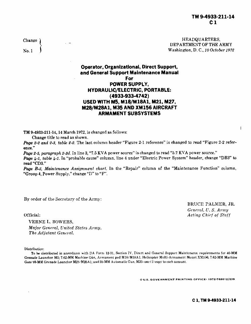
TM 9-4933-211-14, 14 March 1972, is changed as follows:The title is changed as shown above.Page i. Immediately below the title, add the following:To implement the three level maintenance concept, the following changes will be made to this manual, asapplicable:
a. Substitute the words, “Aviation Unit maintenance” for Crew/Operator and Organizational maintenance(first level of maintenance). Also, wherever the symbol for Crew/Operator maintenance (C)is used, change tothe symbol for Aviation Unit maintenance (0).
b. Substitute the words Aviation Intermediate maintenance for Direct Support and General Supportmaintenance (second level of maintenance). Also, wherever the symbol for General Support maintenance (H) isused, change to the symbol for Aviation Intermediate maintenance (F).
c. The Depot level of maintenance remains the same (third level of maintenance).d. Under the new three level maintenance concept, the maintenance codes are as follows: Aviation Unit
Maintenance (0), Aviation Intermediate Maintenance (F), and Depot Maintenance (D).
1
Official:
FRED C. WEYANDGeneral, United States ArmyChief of Staff
PAUL T. SMITHMajor General, United States ArmyThe Adjutant General
Distribution:To be distributed in accordance with DA Form 12-31, Direct and General Support maintenance
requirements for 7.62 MM Machine-Gun/2.75" Rocket Launcher, High Rate, M21 Armament POD M18M18A1,High Rate, M27, 40-MM Grenade Launcher, M28/M28A1/M28A1E1, 20-MM Automatic Gun, M35, 40-MMGrenade Launcher, M5, Mount, Multi-Armament, Helicopter, M156.
2


WARNINGHIGH VOLTAGE
Prior to connecting power supply electrical cablesto a power source, be sure all electrical switches
are in off position.
Power input should be OFF before connectingor disconnecting any test leads to equipment.
Reasonable care must be exercised, whenequipment is under power, to avoid injury
to personnel and / or damage to testequipment or unit under test.
HIGH PRESSURE-HYDRAULICDo not connect or disconnect any hoses when
bypass valve is closed.

TM 9-4933-211-14
Technical Manual HEADQUARTERS,
No. 9-4933-211-14DEPARMENT OF THE ARMYWashington, D.C., 14 March 1972
OPERATOR, ORGANIZATIONAL, DIRECT SUPPORT
AND GENERAL SUPPORT MAINTENANCE MANUAL
FOR
POWER SUPPLY, HYDRAULIC / ELECTRIC, PORTABLE,
(4933-933-4742)
Paragraph
LIST OF ILLUSTRATIONS . . . . . . . . . . . . . . . . . . . . . . . . . . . . . . . . . . . . . . . . . . . . . . . . . . . . . . . . . . . . . . .
LIST OF TABLES . . . . . . . . . . . . . . . . . . . . . . . . . . . . . . . . . . . . . . . . . . . . . . . . . . . . . . . . . . . . . . . . . . . . .
CHAPTERSection
CHAPTERSection
Section
CHAPTERSection
CHAPTERSection
CHAPTER
CHAPTER
APPENDIX
APPENDIX
APPENDIX
1.I.
II.
2.I.
II.III.
3.I.
II.III.IV.V.
4.I.
II.III.
IV.V.
5.I.
II.III.IV.
6.
7.
A.
B.
c.
INTRODUCTION General . . . . . . . . . . . . . . . . . . . . . . . . . . . . . . . . . . . . . . . . . . . . . . . . . . . . . . . . . . . . . . . . . . . . . . . . . . . . . . . . Description and data . . . . . . . . . . . . . . . . . . . . . . . . . . . . . . . . . . . . . . . . . . . . . . . . . . . . . .
OPERATING INSTRUCTIONSControls and instruments . . . . . . . . . . . . . . . . . . . . . . . . . . . . . . . . . . . . . . . . . . . . . . . . . . . . . . . . . . . .Operation under usual conditions . . . . . . . . . . . . . . . . . . . . . . . . . . . . . . . . . . . . . . . . . . . . . . . . . . . . . . . . .O p e r a t i o n u n d e r u n u s u a l c o n d i t i o n s
OPERATOR AND ORGANIZATIONAL MAINTENANCE INSTRUCTIONSService upon receipt of materiel . . . . . . . . . . . . . . . . . .Basic issue items . . . . . . . . . . . . . . . . . .Lubrication instructions . . . . . . . . . . . . . . . . . . . . . . . . . . . . . . . . . . . . . . . . . . . . . . . . . . . . .Preventive maintenance checks and services . . . . . . . . . . . . . . . . . . . . . . . . . . . . . . . . . . Maintenance of power supply . . . . . . . . . . . . . . . .
DIRECT SUPPORT AND GENERAL SUPPORT MAINTENANCE INSTRUCTIONS
Preembarkation inspection of materiel in units alertedfor overseas movement . . . . . . . . . . . . . . . . . . . . . . . . . . . . . . . . . . . . . . . . . . . . . . . . . . . . . . . . . . . . . . . . . . . . . . . . . . . . . . . . . . . . . . . . . . . .
General Maintenance . . . . . . . . . . . . . . . . . . . . . . . . . . . . . . . . . . . . . . . . . . . . . . . . . . . . . . . . . . . . . . . . . . . . . . . . . . . . . . . . . . . . . . . . . Removal and installation of major components and auxiliaries . . . . . . . . . . . . . . . . . . . . . . . . .
REPAIR OF POWER SUPPLY Repair of electrical box assembly . . . . . . . . . . . . . . . . . . . . . . . . . . . . . . . . . . . . . . . . . . . . . . . . . . . . . . . . . . . . . . . . . . Repair of dc power supply . . . . . . . . . . . . . . . . . . . . . . . . . . . . . . . . . . . . . . . . . . . . . . . . . . . . . . . . . . . . . . . . . . .Repair of instrument panel assembly . . . . . . . . . . . . . . . . . . . . . . . . . . . . . . . . . . . . . . . . . . . . . . . . . . . . . . . . . . . . . . . . Repair of case assembly . . . . . . . . . . . . . . . . . . . . . . . . . . . . . . . . . . . . . . . . . . . . . . . . . . . . . . . . . . . . . . . . . . . . . . . . . . . . . . . . . . . . . .
FINAL INSPECTION . . . . . . . . . . . . . . . . . . . . . . . . . . . . . . . . . . . . . . . . . . . . . . . . . . . . . . . . . . . . . . . . . . . . . . . . . . . . . . . . . .
ADMINISTRATIVE STORAGE . . . . . . . . . . . . . . . . . . . . . . . . . . . . . . . . . . . . . . . . . . . . . . . . . . . . . . . . .
REFERENCES . . . . . . . . . . . . . . . . . . . . . . . . . . . . . . . . . . . . . . . . . . . . . . . . . . . . . . . . . . . . . . . . . . . . . . . . .
BASIC ISSUE ITEMS LIST . . . . . . . . . . . . . . . . . . . . . . . . . . . . . . . . . . . . . . . . . . . . . . . . . . . . . . . . .
1-11-4
2-12-3
2-10
3-13-33-53-73-9
4-14-2
4-44-6
4-10
5-15-55-9
5-13
6-1
Page. . .iii
v
1-11-1
2-12-42-6
3-13-33-33-33-3
4-14-1
4-44-44-5
5-15-8
5-175-21
6-1
7-1
A-1
B-1
C-1
I-1i

L I S T O F I L L U S T R A T I O N S
Number
1-1.1-2.2-1.2-2.2-3.3-1.3-2.4-1.
4-1.
4-2
4-2.
4-3.4-4.4-5.4-6.5-1.5-2.5-3.5-4.5-5.5-6.5-7.5-8.5-9.5-10.5-11.5-12.5-13.FO-1.FO-2.
Title
Power Supply . . . .D i s t r i b u t i o n B o x : H E D PP o w e r S u p p l y C o n t r o l P a n e lDistr ibut ion Panel Contro lsP o w e r S u p p l y . R i g h t S i d e V i e wL u b r i c a t i o n I n s t r u c t i o n sH i g h P r e s s u r e F i l t e r . . . . . . . . . . . . . . . . . . . . . . . . . . . . . . . . .Portable Hydraulic / Electric Power Supply: w/Battery BB433A, HEPC-1,
E x t e r n a l G r o u p ( S h e e t 1 o f 2 )Portable Hydraulic / Electric Power Supply: w/Battery BB433A, HEPC-1,
External Group (Sheet 2 of 2)Portable Hydraulic / Electric Power Supply: w/Battery BB433A, HEPC-1,
Internal Group (Sheet 1 of 2) .Portable Hydraulic / Electric Power Supply: w/Battery BB433A, HKPC-1,
Internal Group (Sheet 2 of 2)Power Distribution Box.Power Supply Interconnecting Wiring DiagramPower Supply Hydraulic Piping DiagramDistribution Box Functional DiagramElectrical Box Assembly .Electrical Panel Assembly . . . . . . . .. . . . . . . . . . . . . . . . .. . .. .Height Adjustment of Electrical Box ComponentsElectrical Box Wiring Diagram
Regulator Assembly .. . . . . . .. . . . . . . . . . .. . . . . . . . . . . . . . . . . . . . .Panel Board Assembly ... . .. . . .. . . . . . . . . . . . . . . . . . . . . . . . . . . . . . . . . . .Regulator Assembly Wiring Diagram. . . . . . . .. .. . . . ... . . ... . . . . . . . . . . . .. . . .Instrument Panel Assembly . . . . . . . . . . . . . . . . . . . . . . . . . . . . . . . . . . . . . . . .Instrument Panel Assembly Wiring Diagram . . . . . . . . . . . . . . . . . .Case Assembly . . . . .. . .. . . . . . .. . . . . . . . . . . . . .. . . . . . . . .Power Supply Wiring Diagram . . . . . . . . . . . . . . DC Power Supply Functional Diagram . . . . . . . . . . . .
Page
1-21-32-2
2-32-43-23-5
4-6
4-8
4-10
4-124-144-164-174-19
5-25-45-65-75-9
5-105-115-125-135-165-185-205-22
FO-1FO-2
. . .III

LIST OF TABLES
Number
1-1.2-1.2-2.2-3.3-1.4-1.4-2.
5-1.5-2.
5-3.5-4.5-5.5-6.5-7.
Title
Identification Plates . . . . . . . . . . . . . . . . . . . . . . . . . . . . . . . . . . . . . . . . . . . . . . . .Power Supply Control Panel Controls and Instruments . . . . . . . . . . . . . . . . . . . . . . . . . . . . . . . . . . . . . . . . .Distribution Panel Controls and Instruments . . . . . . . . . . . . . . . . . . . . . . . . . . . . . . . . . . . . . . . . . . . . . . . . . . . .Miscellaneous Power Supply Controls and Instruments . . . . . . . . . . . . . . . . . . . . . . . . . . . . . . . . . . . .Preventive Maintenance Checks and Services . . . . . . . . . . . . . . . . . . . . . . . . . . . . . . . . . . . . . .Troubleshooting . . . . . . . . . . . . . . . . . . . . . . . . . . . . . . . . . . . . . . . . . . . . . . . . .Voltage Regulator Voltage Measurements . . . . . . . . . . . . . . . . . . . . . . . . . . . . . . . . . . . . . . .Electrical Box Assembly Component Inspection . . . . . . . . . . . . . . . . . . . . . . . . . . . . . . . .Electrical Panel Assembly Component Inspection . . . . . . . . . . . . . . . . . . . . . . . . . . . . . . . . . . . . . . . .DC Power Supply Component Inspection . . . . . . . . . . . . . . . . . . . . . . . . .Heatsink Assembly and Resistor Board Component Inspection . . . . . . . . . . . . . . . . . . . . . . . . . . . . . . . . . . . . .Regulator Assembly Component Inspection . . . . . . . . . . . . . . . . . . . . . . . . . . . . . . . . . . . . . . . . . .Panel Board Component Inspection . . . . . . . . . . . . . . . . . . . . . . . . . . . . . . . . . . . . . . . . . . . .
Instrument Panel Assembly Component Inspection . . . . . . . . . . . . . . . . . . . . . . . . . . . . . . . . . . . . . .
Page
1-42-12-22-33-34-1
4 - 35-55-5
5-145-145-145-145-21
v

CHAPTER 1
INTRODUCTION
Section I. GENERAL
1-1. Scope.This manual contains information and
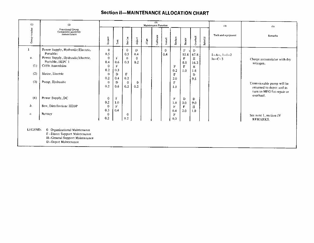
instructions for personnel responsible forperforming operator, organizational, direct supportand general support maintenance of the PortableHydraulic / Electric Power Supply. Maintenanceresponsibilities will apply as reflected in themaintenance allocation chart (Appendix B) and byallocation of repair parts and special tools (see TM9-4933-211-34P).1-2. Forms and Records.
Maintenance forms, records, and reports whichare to be used by maintenance personnel at all
maintenance levels are listed in and prescribed byTM 38-750 (The Army Maintenance ManagementSystems (TAMMS)).1-3. Reporting of errors.
Repor t o f errors, omissions, andrecommendations for improving this publication bythe individual user is encouraged. Reports should besubmitted on DA Form 2028, RecommendedChanges to Publications, and forwarded direct to:Commanding General, Headquarters, U. S. ArmyWeapons Command, ATTN: AMSWE-MAP,Rock Island, Illinois 61201.
Section II. DESCRIPTION AND DATA
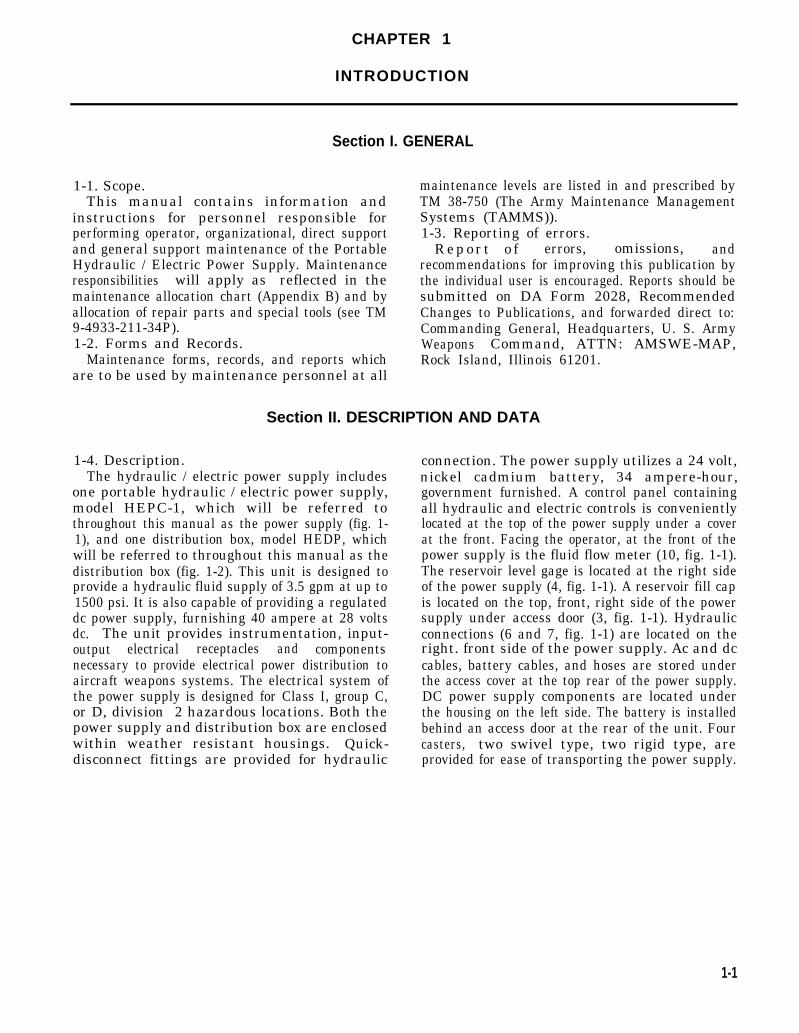
1-4. Description.The hydraulic / electric power supply includes
one portable hydraulic / electric power supply,model HEPC-1, which will be referred tothroughout this manual as the power supply (fig. 1-1), and one distribution box, model HEDP, whichwill be referred to throughout this manual as thedistribution box (fig. 1-2). This unit is designed toprovide a hydraulic fluid supply of 3.5 gpm at up to1500 psi. It is also capable of providing a regulateddc power supply, furnishing 40 ampere at 28 voltsdc. The unit provides instrumentation, input-output electrical receptacles and componentsnecessary to provide electrical power distribution toaircraft weapons systems. The electrical system ofthe power supply is designed for Class I, group C,or D, division 2 hazardous locations. Both thepower supply and distribution box are enclosedwithin weather resistant housings. Quick-disconnect fittings are provided for hydraulic
connection. The power supply utilizes a 24 volt,nickel cadmium battery, 34 ampere-hour,government furnished. A control panel containingall hydraulic and electric controls is convenientlylocated at the top of the power supply under a coverat the front. Facing the operator, at the front of thepower supply is the fluid flow meter (10, fig. 1-1).The reservoir level gage is located at the right sideof the power supply (4, fig. 1-1). A reservoir fill capis located on the top, front, right side of the powersupply under access door (3, fig. 1-1). Hydraulicconnections (6 and 7, fig. 1-1) are located on theright. front side of the power supply. Ac and dccables, battery cables, and hoses are stored underthe access cover at the top rear of the power supply.DC power supply components are located underthe housing on the left side. The battery is installedbehind an access door at the rear of the unit. Fourcasters, two swivel type, two rigid type, areprovided for ease of transporting the power supply.
1-1
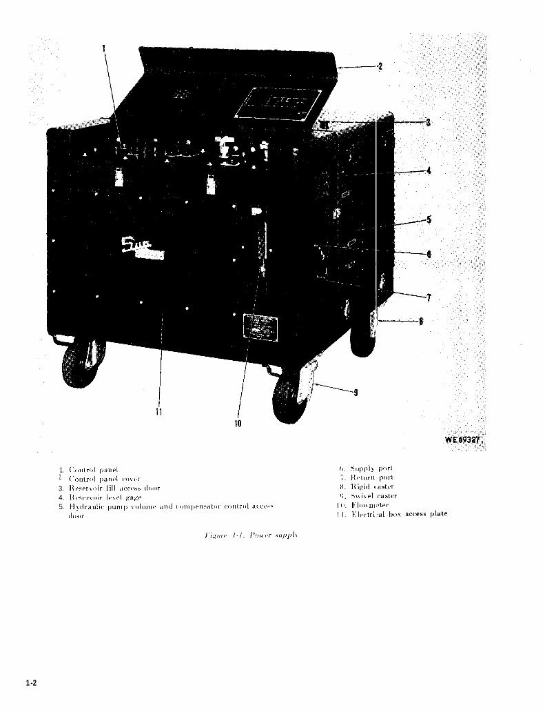
Figure 1-1.
1.2.
3.4.5.
1-2
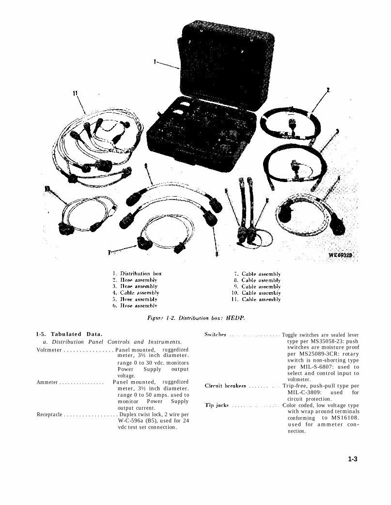
Figure 1-2.
1-5. TabuIated Data.a. Distribution Panel Controls and Instruments.
Voltmeter . . . . . . . . . . . . . . . . Panel mounted, ruggedizedmeter, 3½ inch diameter.range 0 to 30 vdc. monitorsPower Supply output
Ammeter . . . . . . . . . . . . . . . .voltage.
Panel mounted, ruggedizedmeter, 3½ inch diameter.range 0 to 50 amps. used tomonitor Power Supplyoutput current.
Receptacle . . . . . . . . . . . . . . . . . . Duplex twist lock, 2 wire perW-C-596a (B5), used for 24vdc test set connection.
Toggle switches are sealed levertype per MS35058-23: pushswitches are moisture proofper MS25089-3CR: rotaryswitch is non-shorting typeper MIL-S-6807: used toselect and control input tovoltmeter.
Trip-free, push-pull type perMIL-C-3809: used forcircuit protection.
Color coded, low voltage typewith wrap around terminalsconforming to MS16108.used for ammeter con-nection.
1-3
Connectors . . . . . . . . . . . . . . .Input, output, and in-terconnecting receptaclesconforming to MIL-C-5015or MIL-C-26482.
b. Power Supply Controls and Instruments.
High pressure dial gage . . . . . .
Outlet shutoff valve . . . . . . . . . . .
Bypass valve . . . . . . . . . . . . . . . . . . . .
Flowmeter . . . . . . . . . . . . . . . . . . . . . . . .
Switches . . . . . . . . . . . . . . . . . . . . .
Indicator lights . . . . . . . . . . . . . . . . . .
c. Hydraulic Data.Hydraulic reservoir . . . . . . . . . . .Reservoir level gage . . . . . . . . . Reservoir fill and strainer . . . . . . . Reservoir drain . . . . . . . . Low pressure filter . . . . . . .Thermoswitch . . . . . . . . . . . . . .Hydraulic pump . . . . . . . . . . . . .
Check valve . . . . . . . . . . . . . . . . .Differential pressure
switch . . . . . . . . . . . . . . . . . . . . . . . . . . . . . .High pressure filter . . . . . . . . . . . .Supply - portValve, relief . . . . . . . . . . . . . . . . . .Return portHeat exchanger . . . . . . . . . . . . . . .
Accumulator . . . . . . . . . . . . . . . . . . .
Hose assembly and quickdisconnect . . . . . . . . . . . . . . . . . .
Hose assembly and quickdisconnect . . . . . . . . . . . . . . . . . .
0 to 2000 psi range, MS28061-6, indicates system testpressure.
Needle type, controls flow tounit on test.
Needle type. bypasses pumpdischarge.
Variable area glass tube type,range 0.35 to 4.0 gpm, in-dicates fluid flow from unitunder test.
START and stop pushbuttons.running overload, hightemperature, an ddervoltage interlock,
AC power ON, green,differential pressure iupressure filter, red.
Two gallon capacity0, ¼, ½, ¾, Full1½ inch, 100 mesh size½ inch40 mesh strainerPreset to 175 ±4°F
fluidun-
highhigh
Axial piston type, variablevolume, pressure com-pensated
Quick acting poppet type
Adjustable-preset to 35 psi10 micron nominal
Adjustable-preset to 1750 psi
Air / oil type integral coolingfan
1 quart capacity-pistontype-power off 750 psi
AN6264-6-75 with aeroquippart number 340206-4
MS28741-8-0720 withaertoquip part number340206-6
d. Electrical Data.Motor, B1 . . . . . . .. . . . . . . . .
Motor protection, CB1, MK1, OL1 OI2 . . . . . . . . . . . . . . . . . . .
Thermal switch, S3 . . . . . . . . . . . . .
Power input cable . . . . . . . . . . . . . . . .
Dc power supply . . . . . . . . . . . . . . . .
Dc short circuitprotection, CB2 . . . . . . . . . . . .
Dc output cable . . . . . . . . . . . . .
Battery, BT1 . . . . . . . . . . . .
Battery output cable . . . . . . . . . . . .
e. Physical Data.Power supply:
Length . . . . . . . . . . . . . . . . . Depth . . . . . . . . . . . . . . . . . . .Height . . . . . . . . . . . . . . . .Weight . . . . . . . . . . . . . . . .
Distribution box:Depth . . . . . . . . . . . . . . . . . . . . . . . . . . . . . . Height . . . . . . . . . . . . . . . . . . . . . . . . . . .Width . . . . . . . . . . . . . . . . . . . . . . . . . . .Weight . . . . . . . . . . . . . . . . . . . . . . . . .
4 hp, 1440 1730 rpm,220, / 440v, 3 phase, 50 / 60cps integral pump mount,drip proof.
Magnetic Circuit Breaker.magnetic starter and twooverload relays withautomatic reset.
stops motor when fluidtemperature exceeds175°F ± 4°F.
25 ft, 4 conductor, 10 awg,neoprene jacket, with ter-minals for 3/8 inch size studs.
Solid state, 26-30V, 40Acontinuous output, 208 to230 vac, 3 phase, 50 / 60cycle input. Line and loadvoltage regulation 1% .Peak-to-peak ripple at fullload 100 mv. SeriesRegulator. Convectioncooled.
Magnetic circuit breaker andautomatic current limiting.
10 ft long, two conductor, 8awg, neoprene jacket, withone connector, MS3106A-20-8S.
Aircraft type storage battery,nickel / cadmium, 24v,34amp-hr.
10 ft long, neoprene jacket, twoseparate conductors, oneconnector MS3106A-321S.
36 inches36 inches34 inches725 pounds (dry)
18¾ inches12 ?% inches21 inches48 pounds {including hoses
and cables)1-6. Identification Plates.
Refer to table 1-1 for power supply identificationplate tabulation.
Table 1-1. Identification Plates
DescriptionI Location
NOTEControl panel is front nf power supply. Reference to left, right, front. or rear is taken facing the control panel.
Hydraulic schematic plate. Contains schematic diagram ofI
Located on right hand, underside of control panel cover.power supply hydraulic system.
Unit plate. Contains model number and description of power Located on lower, right front of power supply.supply,
Supply port plate. Contains words SUPPLY PORT. Located on front, right side of power supply just abovehydraulic supply port.
1-4
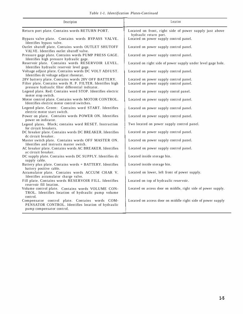
Table 1-1. Identification Plates-Continued
Description
Return port plate. Contains words RETURN PORT.
Bypass valve plate. Contains words BYPASS VALVE.Identifies bypass valve.
Outlet shutoff plate. Contains words OUTLET SHUTOFFVALVE. Identifies outlet shutoff valve.
Pressure gage plate. Contains words PUMP PRESS GAGE.Identifies high pressure hydraulic gage.
Reservoir plate. Contains words RESERVOIR LEVEL.Identifies hydraulic reservoir level gage.
Voltage adjust plate. Contains words DC VOLT ADJUST.Identifies dc voltage adjust rheostat.
28V battery plate. Contains words 28V OFF BATTERY.Filter plate. Contains words H. P. FILTER. Identifies high
pressure hydraulic filter differential indicator.Legend plate. Red: Contains word STOP. Identifies electric
motor stop switch.Motor control plate. Contains words MOTOR CONTROL.
Identifies electric motor control switches.Legend plate. Green: Contains word START. Identifies
electric motor start switch.Power on plate. Contains words POWER ON. Identifies
power on indicator.Legend plates. Black; contains word RESET. Instruction
for circuit breakers.DC breaker plate. Contains words DC BREAKER. Identifies
dc circuit breaker.Master switch plate. Contains words OFF MASTER ON.
Identifies and instructs master switch.AC breaker plate. Contains words AC BREAKER. Identifies
ac circuit breaker.DC supply plate. Contains words DC SUPPLY. Identifies dc
supply cable.Battery plus plate. Contains words + BATTERY. Identifies
battery positive cable.Accumulator plate. Contains words ACCUM CHAR V.
Identifies accumulator charge valve.Fill plate. Contains words RESERVOIR FILL. Identifies
reservoir fill location.Volume control plate. Contains words VOLUME CON-
TROL. Identifies location of hydraulic pump volumecontrol.
Compensator control plate. Contains words COM-PENSATOR CONTROL. Identifies location of hydraulicpump compensator control.
Location
Located on front, right side of power supply just abovehydraulic return port.
Located on power supply control panel.
Located on power supply control panel.
Located on power supply control panel.
Located on right side of power supply under level gage hole.
Located on power supply control panel.
Located on power supply control panel.Located on power supply control panel.
Located on power supply contol panel.
Located on power supply control panel.
Located on power supply control panel.
Located on power supply control panel.
Two located on power supply control panel.
Located on power supply control panel.
Located on power supply control panel.
Located on power supply control panel.
Located inside storage bin.
Located inside storage bin.
Located on lower, left front of power supply.
Located on top of hydraulic reservoir.
Located on access door on middle, right side of power supply.
Located on access door on middle right side of power supply
1-5

CHAPTER 2
OPERATING INSTRUCTIONS
Section I. CONTROLS AND INSTRUMENTS
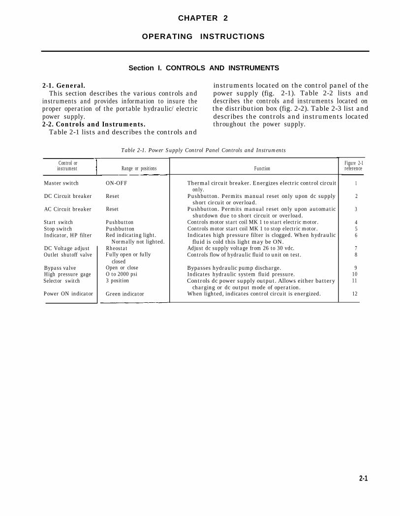
2-1. General. instruments located on the control panel of theThis section describes the various controls and power supply (fig. 2-1). Table 2-2 lists and
instruments and provides information to insure the describes the controls and instruments located onproper operation of the portable hydraulic/ electric the distribution box (fig. 2-2). Table 2-3 list andpower supply. describes the controls and instruments located2-2. Controls and Instruments. throughout the power supply.
Table 2-1 lists and describes the controls and
Table 2-1. Power Supply Control Panel Controls and Instruments
Control orinstrument
Master switch
DC Circuit breaker
AC Circuit breaker
Start switchStop switchIndicator, HP filter
DC Voltage adjustOutlet shutoff valve
Bypass valveHigh pressure gageSelector switch
Power ON indicator
Range or positions
ON-OFF
Reset
Reset
PushbuttonPushbuttonRed indicating light.
Normally not lighted.RheostatFully open or fully
closedOpen or closeO to 2000 psi3 position
Green indicator
Function
Thermal circuit breaker. Energizes electric control circuitonly.
Pushbutton. Permits manual reset only upon dc supplyshort circuit or overload.
Pushbutton. Permits manual reset only upon automaticshutdown due to short circuit or overload.
Controls motor start coil MK 1 to start electric motor.Controls motor start coil MK 1 to stop electric motor.Indicates high pressure filter is clogged. When hydraulic
fluid is cold this light may be ON.Adjust dc supply voltage from 26 to 30 vdc.Controls flow of hydraulic fluid to unit on test.
Bypasses hydraulic pump discharge.Indicates hydraulic system fluid pressure.Controls dc power supply output. Allows either battery
charging or dc output mode of operation.When lighted, indicates control circuit is energized.
Figure 2-1reference
1
2
3
456
78
91011
12
2-1
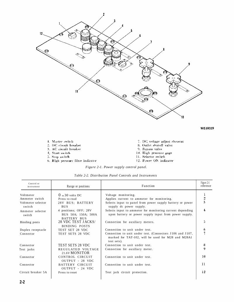
Figure 2-1. Power supply control panel.
Table 2-2. Distribution Panel Controls and Instruments
Control orinstrument Function
VoltmeterAmmeter switchVoltmeter selector
switchAmmeter selector
switch
Binding posts
Duplex receptacleConnector
ConnectorTest jacks
Connector
Connector
Circuit breaker 5A
2-2
Range or positions
0 to 30 volts DCPress to read28V BUS; BATTERY
BUS4 positions; OFF; 28V
BUS 50A; 150A; 500ABATTERY BUS
28 VDC TEST JACKS/BINDING POSTS
TEST SET 28 VDCTEST SETS 28 VDC
TEST SETS 28 VDCREGULATED VOLTAGE
21.6V MONITORCONTROL CIRCUIT
OUTPUT - 28 VDCBATTERY CIRCUIT
OUTPUT - 24 VDCPress to reset
Voltage monitoring.Applies current to ammeter for monitoring.Selects input to panel from power supply battery or power
supply dc power supply.Selects input to ammeter for monitoring current depending
upon battery or power supply input from power supply.
Connection for auxiliary meters.
Connection to unit under test.Connection to unit under test. (Connectors J106 and J107,
marked for TAT-102, will be used for M28 and M28A1test sets).
Connection to unit under test.Connection for auxiliary meter.
Connection to unit under test.
Connection to unit under test.
Test jack circuit protection.
Figure 2-1reference
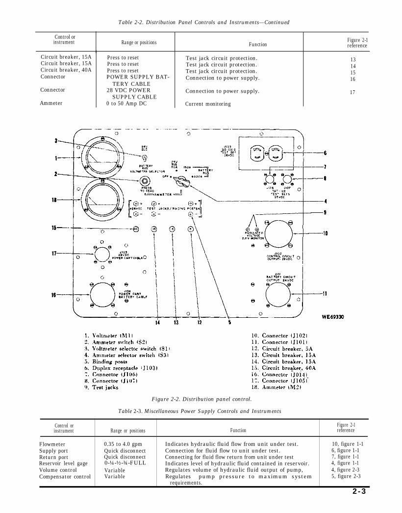
Table 2-2. Distribution Panel Controls and Instruments—Continued
Control or instrument Range or positions Function
Figure 2-1reference
Circuit breaker, 15ACircuit breaker, 15ACircuit breaker, 40AConnector
Connector
Ammeter
Press to resetPress to resetPress to resetPOWER SUPPLY BAT-
TERY CABLE28 VDC POWER
SUPPLY CABLE0 to 50 Amp DC
Test jack circuit protection. 13Test jack circuit protection. 14Test jack circuit protection. 15Connection to power supply. 16
Connection to power supply. 17
Current monitoring
Figure 2-2. Distribution panel control.
Table 2-3. Miscellaneous Power Supply Controls and Instruments
Control or Figure 2-1instrument Range or positions Function reference
Flowmeter 0.35 to 4.0 gpmSupply port Quick disconnectReturn port Quick disconnect
Indicates hydraulic fluid flow from unit under test. 10, figure 1-1Connection for fluid flow to unit under test. 6, figure 1-1Connecting for fluid flow return from unit under test 7, figure 1-1
Reservoir level gage 0-¼-½-¾-FULL Indicates level of hydraulic fluid contained in reservoir. 4, figure 1-1Volume control Variable Regulates volume of hydraulic fluid output of pump,Compensator control
4, figure 2-3Variable Regulates pump pressure to maximum system 5, figure 2-3
requirements.
2 -3
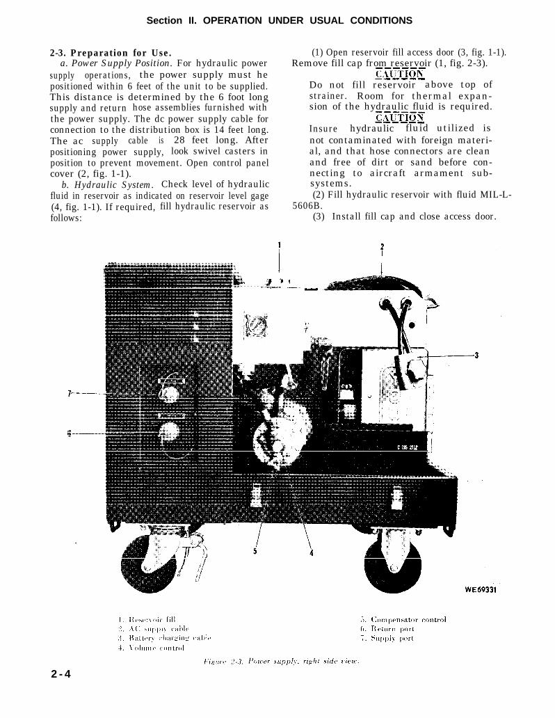
Figure 2-3.
Figure 2-3
Section II. OPERATION UNDER USUAL CONDITIONS
2-3. Preparation for Use. (1) Open reservoir fill access door (3, fig. 1-1). a. Power Supply Position. For hydraulic power Remove fill cap from reservoir (1, fig. 2-3).supply operations, the power supply must hepositioned within 6 feet of the unit to be supplied.This distance is determined by the 6 foot longsupply and return hose assemblies furnished withthe power supply. The dc power supply cable forconnection to the distribution box is 14 feet long.The ac supply cable is 28 feet long. Afterpositioning power supply, look swivel casters inposition to prevent movement. Open control panelcover (2, fig. 1-1).
b. Hydraulic System. Check level of hydraulicfluid in reservoir as indicated on reservoir level gage(4, fig. 1-1). If required, fill hydraulic reservoir asfollows:
Do not fill reservoir above top ofstrainer. Room for thermal expan-sion of the hydraulic fluid is required.
Insure hydraulic fluid utilized isnot contaminated with foreign materi-al, and that hose connectors are cleanand free of dirt or sand before con-necting to aircraft armament sub-systems.(2) Fill hydraulic reservoir with fluid MIL-L-
5606B.(3) Install fill cap and close access door.
2 - 4
c. Hose Connections. Open rear access door andremove two hose assemblies from storage bin.Remove dust caps from ports (6 and 7, fig. l-l) andfrom hose assemblies. Connect one end of hoseassembly to supply port (6) and other end to thecorresponding port on unit to be supplied. Connectone end of second hose assembly to return port (7)and other end to corresponding port on unit to besupplied.
Prior to connecting power supplycables, ascertain that electrical switchesare in OFF position.
d. AC Power Supply Connection. Connect acpower supply cable (2. fig. 2-3) to a 220 / 240 voltac, 3 phase, 50 / 60 Hz, 7.5 KVA power source.
c. Distribution Box Connection. For electricalsupply operations using the distribution box,interconnect the box with the power supply.
(1) Connect DC power supply cable toconnector (J105) (17, fig. 2-2).
(2) Connect battery cable to connector(J104) (16. fig. 2-2).
Disconnect P105 or P104 from powerdistribution panel when in batterycharge mode.
NOTEUsing charging regulator kit, FSN 4933-856-5593, preload accumulator with drynitrogen to approximately 750 psi.
2-4. Starting Power Supply.a. Close outlet shutoff valve (8. fig. 2-1).
Do not connect or disconnect any hoseswhen bypass valve is closed.
b. Open bypass valve (9).c. Place selector switch (11) in OFF position.
Place master switch (1) in ON position. Greenindicator (12) shall light.
d. Press motor start switch (4).2-5. Hydraulic Operation.
a. Starting Hydraulic Operation.(1) Start power supply (para 2-4).
Pressure shall not be set higher than1500 psi.(2) Set pump compensator control (5. fig. 2-3)
if a change from normal 3.5 gpm - 1500 psisetting is desired. To adjust compensator. closeoutlet shutoff valve (8, fig. 2-1) and bypass valve(9). Adjust for desired pressure as read on highpressure gage (10).
Flow shall not be set higher than 3.5gpm.
(3) Set pump volume control (4, fig. 2-3) if achange from normal 3.5 gpm - 1500 psi setting isdesired. To adjust volume control, close outletshutoff valve (8, fig. 2-1) and open bypass valve(9). Adjust for desired flow as read on flowmeter(10, fig. 1-1).
(4) Close bypass valve (9, fig. 2-1).(5) Open outlet shutoff valve (8, fig. 2-1)
fully.(6) Hydraulic fluid is now being applied to
unit undergoing test.h. Stopping Hydraulic Operation.
(1) Close outlet shutoff valve (8, fig. 2-1).(2) Open bypass valve (9).
2-6. DC Supply System Operation.The dc supply system can be used for battery
charging with a limit of 10 to 13 amperes or as aregulated 40 ampere, 26 to 30 volt dc power source.
a. Battery Charging. Refer to TM 11-6140-203-15-2 for information on safety precautions,procedures, and technical data concerning nickelcadre ium batteries. A battery charging cable (3, fig.2-3) with terminals in a plug (P1) is used forbattery charging. To charge a battery, connect plug(P1) to the battery, observing proper polarity.
Insure that location for charging bat-teries is well ventilated. Projectiveclothing and equipment will be worn asrequired by AR 385-32. Insure againstsmoking or proximity of flame or sparkproducing equipment in the batterycharging area.(1) Start power supply (par 2-4).(2) Place selector switch (11, fig. 2-1) in
BATTERY CHARGE position.(3) Refer to TM 11-6140-203-15-2 for
information on battery temperature limitations andhydrometer readings.
(4) To stop battery charging, place selectorswitch (11) in OFF position.
b. DC Power Supply. Output of 40 amperes at26 to 30 volts is available through the use of the dcpower supply cable. The power supply is notequipped with monitoring instruments for the dcpower supply output. The distribution box or otherexternal meters must be used for monitoring.
(1) Start power supply (para 2-4).(2) Place selector switch (11, fig. 2-1) in DC
POWER SUPPLY position.(3) Use dc voltage adjust rheostat (7, fig. 2-1)
as required to increase or decrease the outputvoltage.
(4) To stop the dc power supply output, placeselector switch (11) in OFF position.2-7. Procedures During Operation.
During hydraulic or electric operation of thepower supply observe the following:
2-5
a. If an emergency should arise during hydraulicoperation (ruptured hose, etc.) or if, for any otherreason it is necessary to immediately stop hydraulicfluid pressure flow to the unit undergoing test, openbypass valve (9, fig. 2-1).
b. If red indicator (6, fig. 2-1) should lightduring operation, stop power supply and servicehigh pressure filter (see para 3-9). This light maycome on if the hydraulic fluid is extremely cold andremain on until the fluid has warmed. However, iflight remains on the high pressure must be checked.
c. If temperature of hydraulic fluid reaches 175degrees F or higher, power supply will shut downautomatically through the action of thermostaticswitch (S3).
d. The power supply will shutdownautomatically as a result of a short circuit in eitherthe ac or dc systems. If such shutdown occurs,check dc circuit breaker (2, fig. 2-1) or ac circuitbreaker (3). If circuit breaker has tripped, check
appropriate circuit for cause and then reset circuitbreaker.
c. During operation. listen for unusual noisesand be alert for any abnormal sound, smell, sight,or feel which may indicate a pending malfunction.2-8. Stopping Power Supply.
a. Stop hydraulic operation (para 2-5) or dcsupply system operation (para 2-6).
b. Press motor stop switch (5, fig. 2-1).c. Place master switch (1) in OFF position.
Green indicator (12) shall extinguish.2-9. Procedures After Operation
When supply operations have been completedand unit is shut down, perform the following stepsto secure the power supply.
a. Disconnect and cap all external hoses. Placeprotective caps on outlet ports.
b. Disconnect all electrical cables.c. Place hoses and cables in storage bin.d. Close control panel cover and any access
doors that were opened during operation.
Section Ill. OPERATION UNDER UNUSUAL CONDITIONS
2-10. Operation in Extreme Cold.The power supply is designed to operate at
temperatures above zero degrees Fahrenheit, butnot below this temperature. Where the powersupply is subjected to sub-zero temperatures,adequate protection should be provided against thedeteriorating effects of wind, snow, and ice. Whenpractical, portable electric heaters may be placedinside the power supply to raise ambienttemperature to at least zero degrees Fahrenheit.Remove heater before placing power supply inoperation. Refer to TM 9-207, Operation andMaintenance of Army Materiel in Extreme ColdWeather 0° to - 65° F.2-11. Operation in Extreme Heat and High
Humidity.The power supply is designed to operate at
temperatures up to 125 degrees F., but prolongedexposure to environments of excessively hightemperature and humidity requires specialtreatment, with particular attention to the use ofdesiccants to inhibit corrosive action due to highmoisture content.
2-12. Operation in Sand, Snow, or Mud.Inspect power supply frequently. Clean out and
remove accumulated dust, sand, or mud. Wipeelectrical components with a dampened soft cloth.Clean interior or power supply with a low pressurejet of dry air. Keep access doors closed wheneverpossible.2-13. Operation in Salt Water Areas.
Adequate use of desiccants will reduce corrosiondue to high humidity conditions and salt ladenatmosphere. Clean power supply frequently withfresh water and approved solvent.
To prevent electrical shock whencleaning with water, be sure electricswitch is closed, power off, and cablesdisconnected. Insure that dust coversare on cable connectors.
2-14. Operation at High Altitudes.The power supply is designed to operate
satisfactorily at altitudes ranging from sea level to15,000 feet.
2-6
CHAPTER 3
OPERATOR AND ORGANIZATIONAL
MAINTENANCE INSTRUCTIONS
Section l. SERVICE UPON RECEIPT OF MATERIEL
3-1. General. any malfunctions. The shipping crate and otherWhen new materiel is first received by the using packaging materials should be retained for reuse.
organization. inspect all assemblies, and For preventive-maintenance checks and services,subassenlblies to be sure they are properly refer to table 3-1. Refer to figure 3-1 forassembled, secured, cleaned, correctly adjusted and lubrication.lubricated. Make a record of any missing parts and
3-1
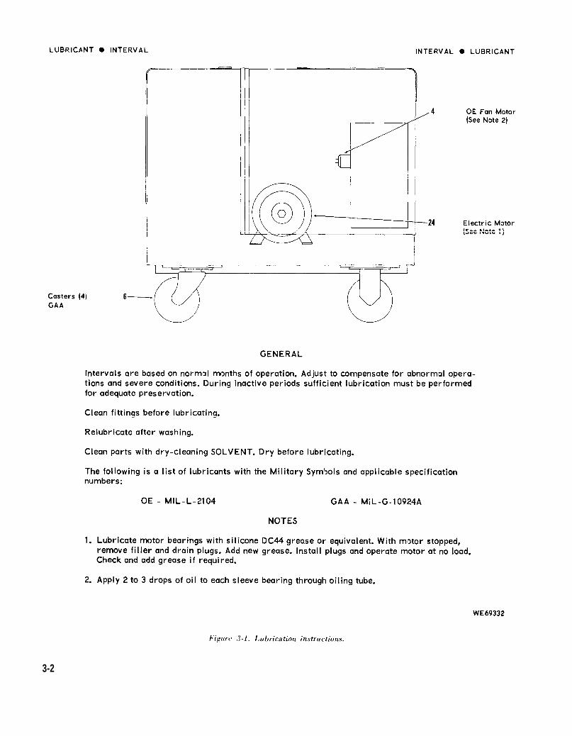
Figure 3-1.
3-2
3-2. Accumulator. regulator kit, FSN 4933-856-5593 and applyThe hydraulic system accumulator should nitrogen to accumulator charging valve located on
maintain a 1500 psi dry nitrogen charge when lower left side of power supply near the front. Thispower supply is turned on, 750 psi when not in valve is identified by an identification plate.operation. To replenish this charge, use charging
3-3. General.
Section II. BASIC ISSUE ITEMS
3-4. Basic Issue Items List. No repair parts, tools, or accessories are issued Not applicable.
with the portable hydraulic / electric power supply.
Section III. LUBRICATION INSTRUCTIONS
3-5. General. 3-6. Service Intervals.Detailed lubrication instructions for this Service intervals prescribed in figure 3-1 are the
quipment are shown in figure 3-1. minimum for usual operating conditions.
Section IV. PREVENTIVE MAINTENANCE CHECKS AND SERVICES
3-7. General. ready for operation at all times, it must be inspectedThis section contains instructions for performing systematically so that defects may be discovered
the periodic preventive maintenance checks and and corrected before they result in serious damageservices required to maintain the power supply. or failure. The necessary preventive maintenance3-8. Preventive Maintenance Checks and check and services to be performed are listed in
Services. table 3-1.a. General. To insure that the power supply is b. Preventive Maintenance Checks and
Services. Refer to table 3-1.
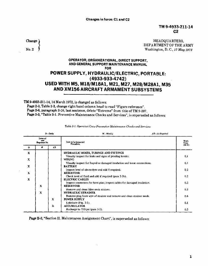
Table 3-1. Preventive Maintenance Checks and Services
Item
Hydraulic hoses, tubing,and fittings
Wiring
BatteryReservoirElectrical cables
ReservoirLOW pressure hydraulic
strainerPower supplyPower supplyAccumulator
Interval
Daily
Daily
DailyDailyDaily
WeeklyWeekly
As requiredWeeklyQuarterly
Prodecure
Visually inspect for leaks and signs of pending breaks.
Visually inspect for frayed or damaged insulation and looseconnections.
Inspect level of electrolyte and add if required.Check level of fluid and add if required.Inspect connectors for bent pins. Inspect cable for damaged
insulation.Remove and clean filler neck strainer.Remove plug from wye of strainer and remove and clean
strainer mesh with solvent.Lubricate,Clean.Recharge to 750 psi.
Section V. MAINTENANCE OF POWER SUPPLY
Reference
Paragraph 2-3b
Figure 3-1TM 9-208-1Paragraph 3-2
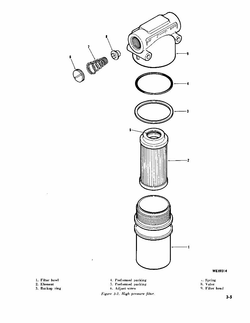
3-9. High Pressure Filter. a. Cut and remove safety wiring between filterRed indicating light (6, fig. 2-1) will light when bowl (1, fig. 3-2) and filter head (9).
the high pressure filter is clogged. When this b. Using a wrench on wrench pad at bottom ofcondition occurs, service the high pressure filter as filter bowl, unscrew bowl from head. Remove bowlfollows:
3-3

(1), backup ring (3), and preformed packing (4) threads on head (9) and bowl (1) with hydraulicfrom head (9). Remove element (2) from bowl. fluid.
c. Wash metal parts with cleaning solvent, e. Install element (2) in bowl (1). PositionFederal Specification P-S-661 and dry with performed packing (4) and backup ring (3) in headcompressed air. Replace filter element and (9) and screw bowl (1) into filter head.preformed packing (4). f. Tighten filter bowl in filter head using 150 in-
d. Before reassembly, lubricate preformed lb torque. Safety wire filter bowl to filter head.packing (4) and (5) with hydraulic fluid. Lubricate
3-4
3-5Figure 3-2.

CHAPTER 4
DIRECT SUPPORT AND GENERAL SUPPORT
MAINTENANCE INSTRUCTIONS
Section I. REPAIR PARTS, SPECIAL TOOLS AND EQUIPMENT
4-1. Repair Parts, Special Tools, and Refer to TM 9-4933-211-34P.Equipment.
Section Il. TROUBLESHOOTING
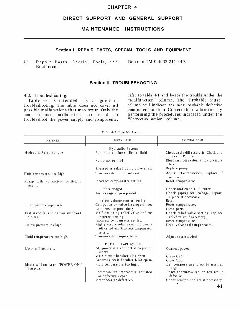
4-2. Troubleshooting.Table 4-1 is intended
troubleshooting. The table
refer to table 4-1 and locate the trouble under theas a guide in “Malfunction” column. The “Probable cause”
does not cover all column will indicate the most probable defectivepossible malfunctions that may occur. Only the component or item. Correct the malfunction bymore common malfunctions are listed. To performing the procedures indicated under thetroubleshoot the power supply and components, “Corrective action” column.
Table 4-1. Troubleshooting
Malfunction Probable Cause Corrective Action
Hydraulic Pump Failure
Fluid temperature too high
Pump fails to deliver sufficientvolume
Pump fails to compensate
Test stand fails to deliver sufficientpressure
System pressure too high.
Fluid temperature too high.
Motor will not start.
Motor will not start “POWER ON”’lamp on.
Hydraulic SystemPump not getting sufficient fluid
Pump not primed
Sheared or seized pump drive shaftThermoswitch improperly set
Incorrect compensator setting
L. I’. filter cloggedAir leakage at pump inlet
Incorrect volume control setting.Compensator valve improperly setCompensator ports dirtyMalfunctioning relief valve and /or
incorrect settingIncorrect compensator settingHigh pressure relief valve improperly
adj us ted and incorrect compensatorsetting.
Thermoswitch improerly set.
Electric Power SystemAC power not connected to power
supply.Main circuit breaker CB1 open.Control circuit breaker DB3 open.Fluid temperature too high.
Thermoswitch improperly adjustedor defective - open.
Motor Starter defective.
Check and refill reservoir. Check andclean L. P. filter.
Bleed air from system at low pressurefilter.
Replace pump.Adjust thermoswitch, replace if
necessary.Reset compensator.
Check and clean L. P. filter.Check piping for leakage, repair,
replace if necessary.Reset.Reset compensator.Clean ports.Check relief valve setting, replace
relief valve if necessary.Reset compensator.Reset valve and compensator.
Adjust thermoswitch.
Connect power.
Close CB1.Close CB3.Let temperature drop to normal
range.Reset thermoswitch or replace if
defective.Check starter. replace if necessary.
4-1
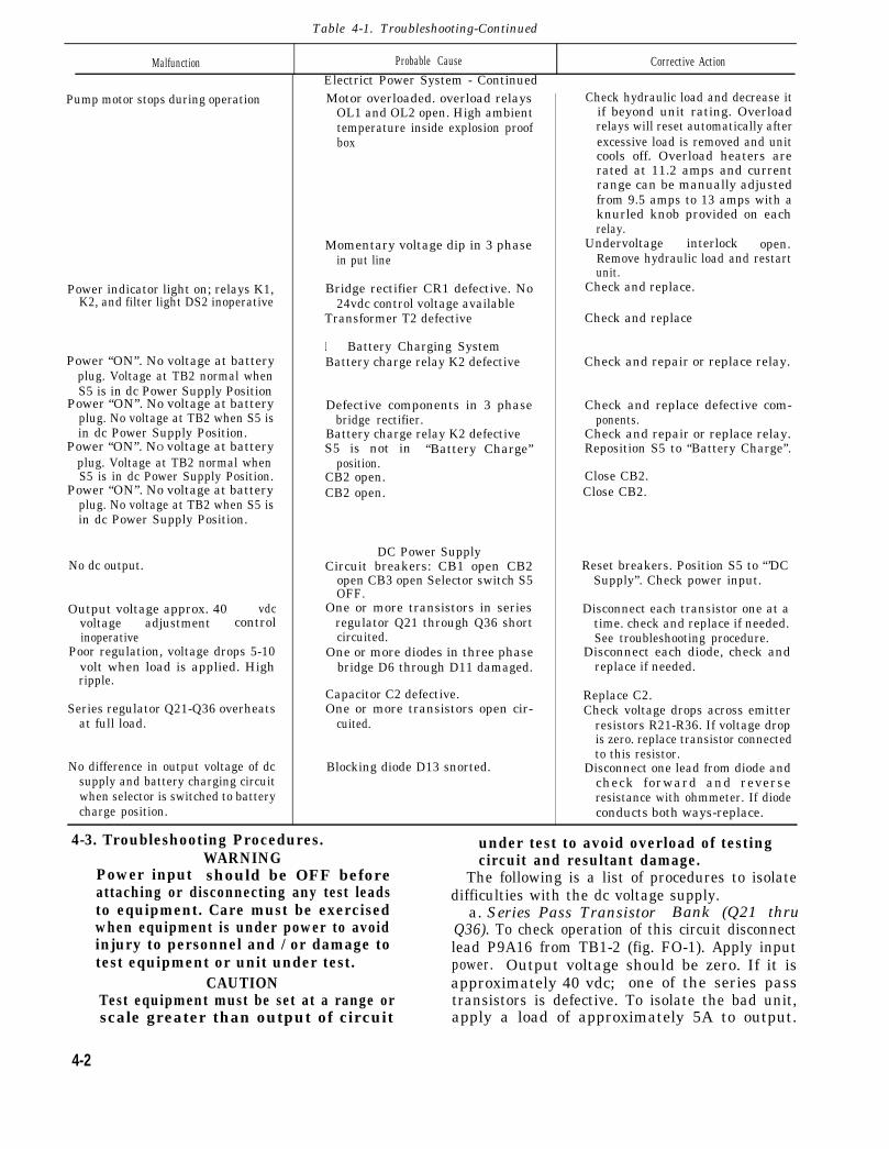
Table 4-1. Troubleshooting-Continued
Malfunction Probable Cause Corrective ActionElectrict Power System - Continued
Pump motor stops during operation Motor overloaded. overload relaysOL1 and OL2 open. High ambienttemperature inside explosion proofbox
Momentary voltage dip in 3 phasein put line
Power indicator light on; relays K1,K2, and filter light DS2 inoperative
Power “ON”. No voltage at batteryplug. Voltage at TB2 normal whenS5 is in dc Power Supply Position
Power “ON”. No voltage at batteryplug. No voltage at TB2 when S5 isin dc Power Supply Position.
Power “ON”. NO voltage at batteryplug. Voltage at TB2 normal whenS5 is in dc Power Supply Position.
Power “ON”. No voltage at batteryplug. No voltage at TB2 when S5 isin dc Power Supply Position.
No dc output.
Output voltage approx. 40 vdcvoltage adjustment controlinoperative
Poor regulation, voltage drops 5-10volt when load is applied. Highripple.
Series regulator Q21-Q36 overheatsat full load.
No difference in output voltage of dcsupply and battery charging circuitwhen selector is switched to batterycharge position.
Bridge rectifier CR1 defective. No24vdc control voltage available
Transformer T2 defective
Battery Charging SystemBattery charge relay K2 defective
Defective components in 3 phasebridge rectifier.
Battery charge relay K2 defectiveS5 is not in “Battery Charge”
position.CB2 open.CB2 open.
DC Power SupplyCircuit breakers: CB1 open CB2
open CB3 open Selector switch S5OFF.
One or more transistors in seriesregulator Q21 through Q36 shortcircuited.
One or more diodes in three phasebridge D6 through D11 damaged.
Capacitor C2 defective.One or more transistors open cir-
cuited.
Blocking diode D13 snorted.
Check hydraulic load and decrease itif beyond unit rating. Overloadrelays will reset automatically afterexcessive load is removed and unitcools off. Overload heaters arerated at 11.2 amps and currentrange can be manually adjustedfrom 9.5 amps to 13 amps with aknurled knob provided on eachrelay.
Undervoltage interlock open.Remove hydraulic load and restartunit.
Check and replace.
Check and replace
Check and repair or replace relay.
Check and replace defective com-ponents.
Check and repair or replace relay.Reposition S5 to “Battery Charge”.
Close CB2.Close CB2.
Reset breakers. Position S5 to “’DCSupply”. Check power input.
Disconnect each transistor one at atime. check and replace if needed.See troubleshooting procedure.
Disconnect each diode, check andreplace if needed.
Replace C2.Check voltage drops across emitter
resistors R21-R36. If voltage dropis zero. replace transistor connectedto this resistor.
Disconnect one lead from diode andcheck forward and reverseresistance with ohmmeter. If diodeconducts both ways-replace.
4-3. Troubleshooting Procedures.WARNING
Power input should be OFF beforeattaching or disconnecting any test leadsto equipment. Care must be exercisedwhen equipment is under power to avoidinjury to personnel and / or damage totest equipment or unit under test.
under test to avoid overload of testingcircuit and resultant damage.
The following is a list of procedures to isolatedifficulties with the dc voltage supply.
a. Series Pass Transistor Bank (Q21 thruQ36). To check operation of this circuit disconnectlead P9A16 from TB1-2 (fig. FO-1). Apply inputpower. Output voltage should be zero. If it is
CAUTION approximately 40 vdc; one of the series passTest equipment must be set at a range or transistors is defective. To isolate the bad unit,scale greater than output of circuit apply a load of approximately 5A to output.
4-2
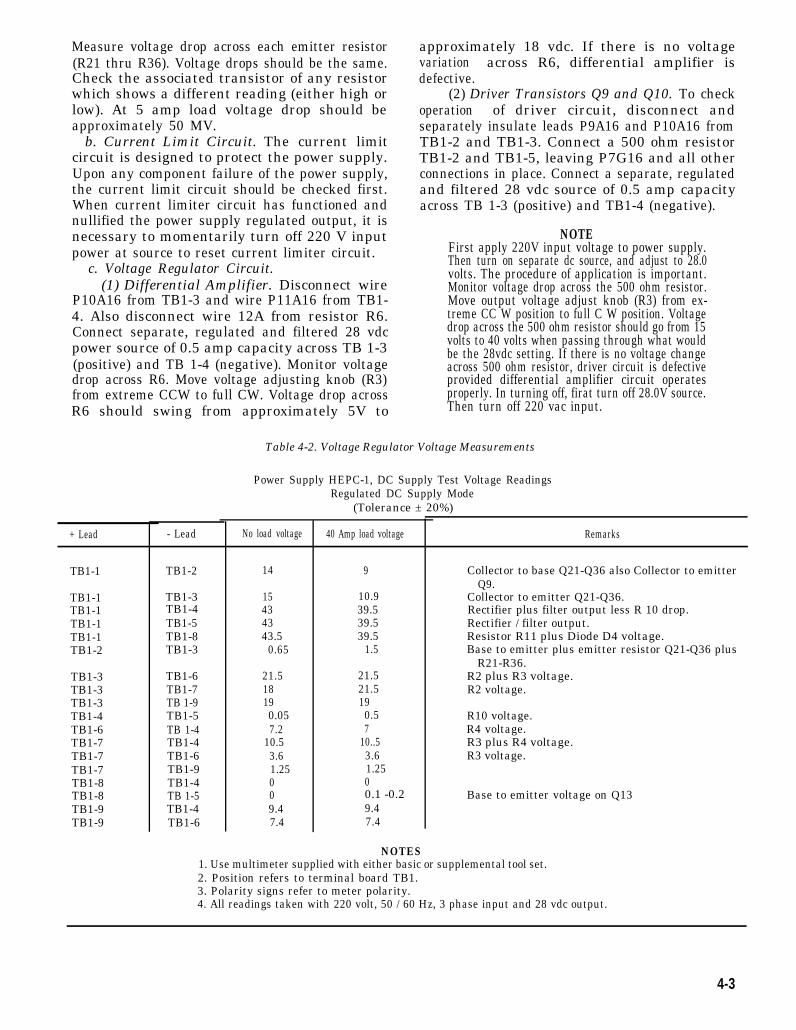
Measure voltage drop across each emitter resistor(R21 thru R36). Voltage drops should be the same.Check the associated transistor of any resistorwhich shows a different reading (either high orlow). At 5 amp load voltage drop should beapproximately 50 MV. b. Current Limit Circuit. The current limit
circuit is designed to protect the power supply.Upon any component failure of the power supply,the current limit circuit should be checked first.When current limiter circuit has functioned andnullified the power supply regulated output, it isnecessary to momentarily turn off 220 V inputpower at source to reset current limiter circuit.
c. Voltage Regulator Circuit.(1) Differential Amplifier. Disconnect wire
P10A16 from TB1-3 and wire P11A16 from TB1-4. Also disconnect wire 12A from resistor R6.Connect separate, regulated and filtered 28 vdcpower source of 0.5 amp capacity across TB 1-3(positive) and TB 1-4 (negative). Monitor voltagedrop across R6. Move voltage adjusting knob (R3)from extreme CCW to full CW. Voltage drop acrossR6 should swing from approximately 5V to
+ Lead
TB1-1
TB1-1TB1-1TB1-1TB1-1TB1-2
TB1-3TB1-3TB1-3TB1-4TB1-6TB1-7TB1-7TB1-7TB1-8TB1-8TB1-9TB1-9
- Lead
TB1-2
TB1-3TB1-4TB1-5TB1-8TB1-3
TB1-6TB1-7TB 1-9TB1-5TB 1-4TB1-4TB1-6TB1-9TB1-4TB 1-5TB1-4TB1-6
approximately 18 vdc. If there is no voltagevariation across R6, differential amplifier isdefective.
(2) Driver Transistors Q9 and Q10. To checkoperation of driver circuit, disconnect andseparately insulate leads P9A16 and P10A16 fromTB1-2 and TB1-3. Connect a 500 ohm resistorTB1-2 and TB1-5, leaving P7G16 and all otherconnections in place. Connect a separate, regulatedand filtered 28 vdc source of 0.5 amp capacityacross TB 1-3 (positive) and TB1-4 (negative).
NOTEFirst apply 220V input voltage to power supply.Then turn on separate dc source, and adjust to 28.0volts. The procedure of application is important.Monitor voltage drop across the 500 ohm resistor.Move output voltage adjust knob (R3) from ex-treme CC W position to full C W position. Voltagedrop across the 500 ohm resistor should go from 15volts to 40 volts when passing through what wouldbe the 28vdc setting. If there is no voltage changeacross 500 ohm resistor, driver circuit is defectiveprovided differential amplifier circuit operatesproperly. In turning off, firat turn off 28.0V source.Then turn off 220 vac input.
Table 4-2. Voltage Regulator Voltage Measurements
Power Supply HEPC-1, DC Supply Test Voltage ReadingsRegulated DC Supply Mode
(Tolerance ± 20%)
No load voltage
14
15434343.5
0.65
21.518190.057.2
10.53.61.25009.47.4
40 Amp load voltage
9
10.939.539.539.5
1.5
21.521.5190.57
10..53.61.2500.1 -0.29.47.4
NOTES
Remarks
Collector to base Q21-Q36 also Collector to emitterQ9.
Collector to emitter Q21-Q36.Rectifier plus filter output less R 10 drop.Rectifier / filter output.Resistor R11 plus Diode D4 voltage.Base to emitter plus emitter resistor Q21-Q36 plus
R21-R36.R2 plus R3 voltage.R2 voltage.
R10 voltage.R4 voltage.R3 plus R4 voltage.R3 voltage.
Base to emitter voltage on Q13
1. Use multimeter supplied with either basic or supplemental tool set.2. Position refers to terminal board TB1.3. Polarity signs refer to meter polarity.4. All readings taken with 220 volt, 50 / 60 Hz, 3 phase input and 28 vdc output.
4-3
Section III. PREEMBARKATION INSPECTION OF MATERIELIN UNITS ALERTED FOR OVERSEAS MOVEMENT
4-4. General. 4-5. Specific Inspection Points for PortableThis inspection is conducted on materiel in Hydraulic / Electric Power Supply.
alerted units scheduled for overseas duty to insure a. Check hose, tube, and cable assemblies forthat such materiel will not become unserviceable in leaks, shorts, frayings, breaks, or damageda relatively short time. It prescribes a higher couplings and connectors.percentage of remaining usable life in serviceable b. Check for availability of dust caps for hosemateriel to meet a specific need beyond minimum connectors.serviceability. c. Check conditions of controls and indicators.
d. Check hinges and fasteners for damage thatwould hinder free operation.
Section IV. GENERAL MAINTENANCE
4-6. General.Information and instructions contained herein
are provided for personnel performing direct andgeneral support maintenance on the materiel. Insubsequent chapters of this technical manual, themain assemblies of the power supply aredisassembled, inspected, cleaned, replaced orrepaired, and assembled. The illustrations in thismanual are numbered in the sequence ofdisassembly. W hen assembling, the reverse order ofdisassembly will be followed unless otherwiseinstructed. Subsequent reference to componentsbeing worn and requiring replacement is intendedto mean that only those items or mechanisms wornto a degree that affects functioning will be replaced.4-7. Repair Methods.
a. Disassembly and Assembly Procedures.(1) In disassembling a unit, remove the major
subassemblies and assemblies whenever possible.Subassemblies may then be disassembled, asnecessary, into individual parts.
(2) During assembly, subassemblies should beassembled first and then installed to form acomplete unit.
(3) Complete disassembly of a unit is notalways necessary in order to make a required repairor replacement. Good judgement should beexercised to keep disassembly and assemblyoperations to a minimum.
b. Replacement of Parts.(1) When assembling a unit, replace defective
spring pins with new ones. If screws, bolts, washers,or nuts are damaged, they should be replaced.
(2) Springs should be replaced if they fail tofunction properly.
(3) If a required new part is not available,reconditioning of the old part is required. Suchparts should be examined carefully, afterreconditioning, to determine their suitability.
4-4
c. Use of Tools.(1) Care must be exercised to use tools that
are suitable for the task to be performed in order toavoid mutilation of parts and / or damage to tools.Use aircraft armament repairman basic tool setMOS 45J, and aircraft armament repairmansupplemental tool set, MOS 45J.
(2) Keep tools clean and work with cleanparts. The rules of good housekeeping must beobserved.
d. Repair and Replacement of Bushings.(1) If a bushing is drilled, or has a groove to
provide lubrication, be sure these openings areclean before assembling the parts.
(2) Extreme care must be exercised wheninstalling bushings. An arbor press should be used,when possible. If an arbor press is not available,hold a clean wood block against the bushing andstrike the block with a hammer. Start the bushingstraight and avoid cocking it in the bore.
e. Finish of Metals.(1) Painted surfaces of the power supply, if
chipped or cracked, may be repainted.(2) Exposed electrical components will be
coated lightly with oil varnish MIL-V-173B.f. Repair of Damaged Machine and Polished
Surfaces. Smooth rough spots, scores, burrs,galling. and gouges from damaged machine andpolished surfaces so that the part will efficientlyperform its normal function. The finish of therepaired part is to approximate that of the originalfinish. In performing any of these operations,critical dimensions must not be altered.
g. Removal of Rust or Corrosion. Removecorrosion from all parts of the materiel. To removerust or corrosion, the use of crocus cloth, vaporblast equipment. or wipe-on type phosphoric acidmetal conditioner is recommended.
4-8. Cleaning.a. Cleaning Materiel Received from
Storage. Remove all rust spots from highly finishedsurfaces with a light application of crocus cloth.Use grade 2 / 0 abrasive cloth on ordinary machinefinished surfaces.
b. Cleaning After Repair. After repairoperations and prior to assembly, remove shop dirtand other foreign matter from all metal surfaces.Clean with cloths soaked in dry cleaning solvent ormineral spirits paint thinner.
c. Cleaning After Shop Inspection. Applypreservatives as soon as possible after cleaning.
d. Electrical Parts. Clean all electrical parts inaccordance with TM 9-247.
e. Rubber Parts Other Than Electrical. Cleanrubber parts with soap and warm water. Applycoating of powdered technical talcum, FederalSpecification, ZZ-T-416 to preserve the rubber.4-9. Lubrication and Preservation.
a. Lubrication. Refer to figure 3-1 forlubricating instructions for the power supply.
b. Preservation. After cleaning and drying,immediately coat unpainted metal surfaces with anoil or grease, as appropriate.
Section V. REMOVAL AND INSTALLATION OF MAJOR
4-10. General.a. The order of removal is
illustration index numberreferenced illustrations.
COMPONENTS AND AUXILIARIES
d. Disconnect hydraulic lines from componentsin accordance with to be removed.Cap or otherwise protect open hy-sequence of the draulic lines to prevent entrance of dirt or foreign
material into hydraulic system.b. Installation is in reverse order of removal
unless otherwise indicated. 4-11. Removal.c. Tag for identification and disconnect a. Refer to figure 4-1 and disassemble power
electrical leads from components to be removed. supply external components.
4-5
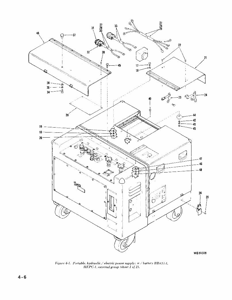
Figure 4-1.
4 - 6
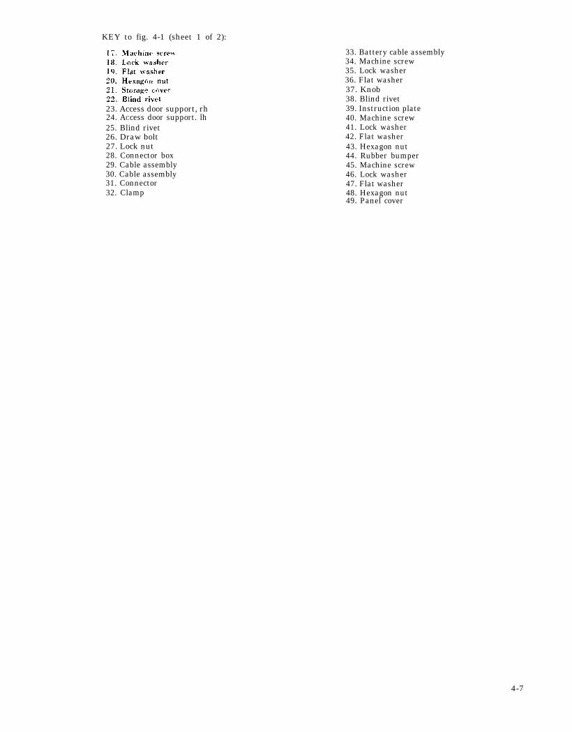
KEY to fig. 4-1 (sheet 1 of 2):
23. Access door support, rh24. ACcess door support. lh25. Blind rivet26. Draw bolt27. Lock nut28. Connector box29. Cable assembly30. Cable assembly31. Connector32. Clamp
4-7
33. Battery cable assembly34. Machine screw35. Lock washer36. Flat washer37. Knob38. Blind rivet39. Instruction plate40. Machine screw41. Lock washer42. Flat washer43. Hexagon nut44. Rubber bumper45. Machine screw46. Lock washer47. Flat washer48. Hexagon nut49. Panel cover
4-8
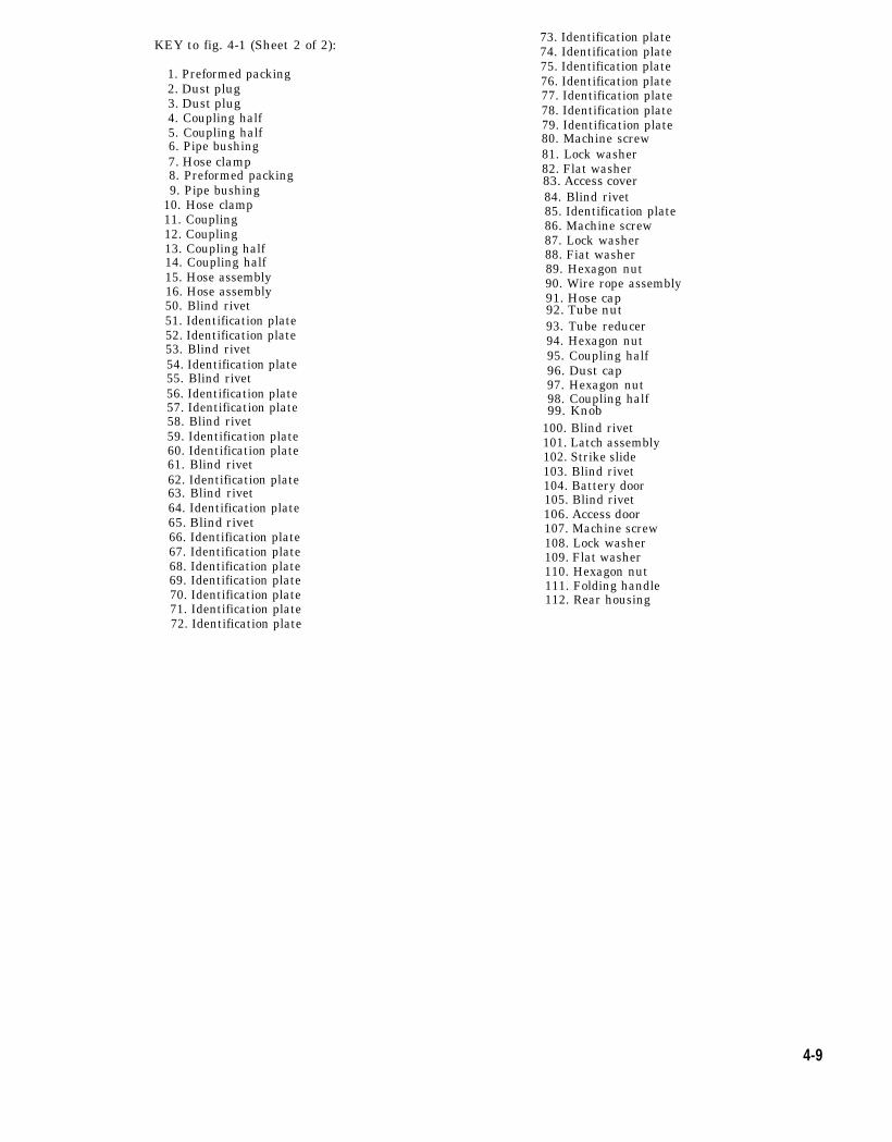
KEY to fig. 4-1 (Sheet 2 of 2):
1. Preformed packing2. Dust plug3. Dust plug4. Coupling half5. Coupling half6. Pipe bushing7. Hose clamp8. Preformed packing9. Pipe bushing
10. Hose clamp11. Coupling12. Coupling13. Coupling half14. Coupling half15. Hose assembly16. Hose assembly50. Blind rivet51. Identification plate52. Identification plate53. Blind rivet54. Identification plate55. Blind rivet56. Identification plate57. Identification plate58. Blind rivet59. Identification plate60. Identification plate61. Blind rivet62. Identification plate63. Blind rivet64. Identification plate65. Blind rivet66. Identification plate67. Identification plate68. Identification plate69. Identification plate70. Identification plate71. Identification plate72. Identification plate
73. Identification plate74. Identification plate75. Identification plate76. Identification plate77. Identification plate78. Identification plate79. Identification plate80. Machine screw81. Lock washer82. Flat washer83. Access cover84. Blind rivet85. Identification plate86. Machine screw87. Lock washer88. Fiat washer89. Hexagon nut90. Wire rope assembly91. Hose cap92. Tube nut93. Tube reducer94. Hexagon nut95. Coupling half96. Dust cap97. Hexagon nut98. Coupling half99. Knob
100. Blind rivet101. Latch assembly102. Strike slide103. Blind rivet104. Battery door105. Blind rivet106. Access door107. Machine screw108. Lock washer109. Flat washer110. Hexagon nut111. Folding handle112. Rear housing
4-9
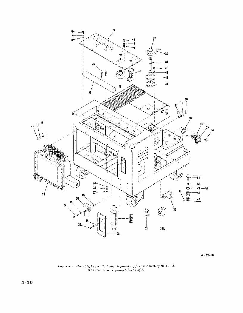
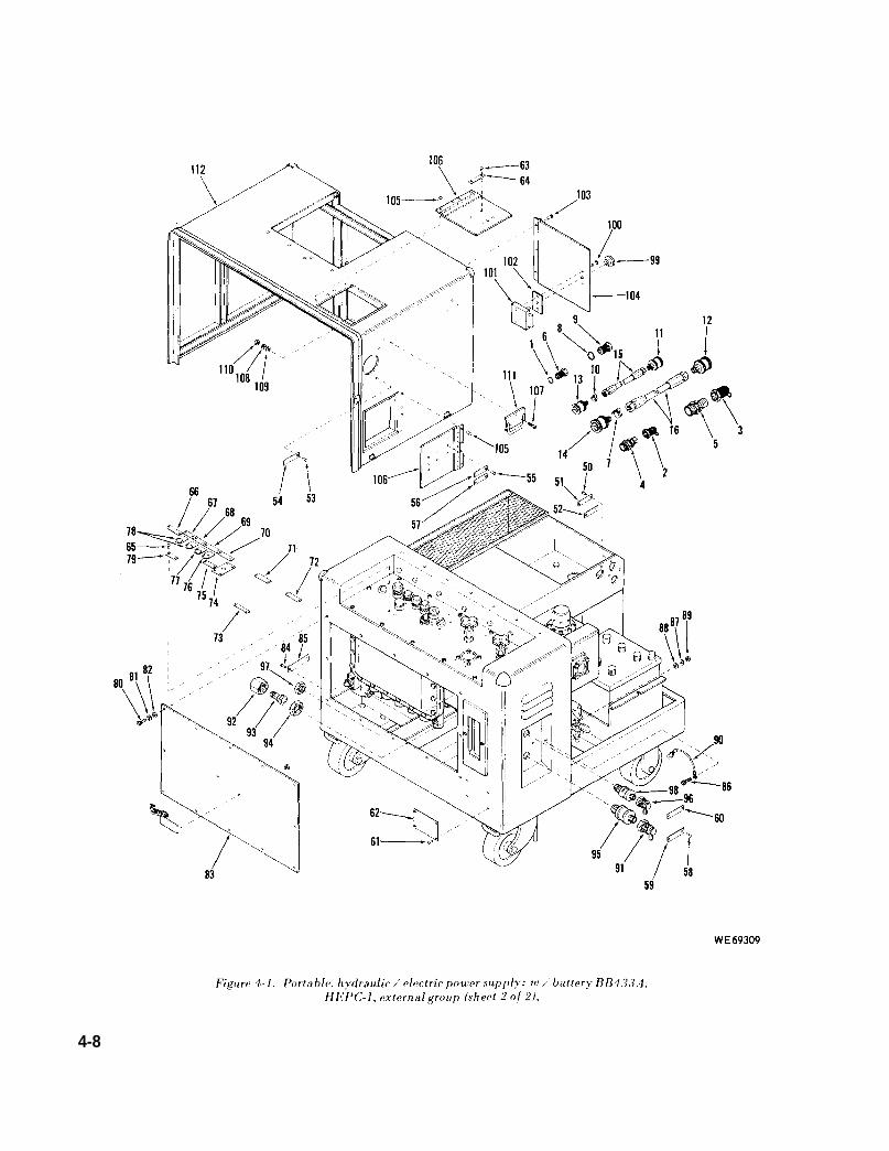
Figure 4-2.
4 -10
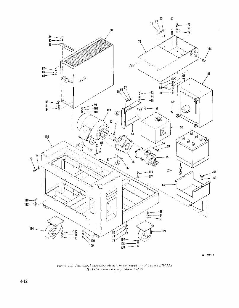
b. Refer to figure 4-2 and disassemble powersupply internal components.
KEY to fig. 4-2 (sheet 1 of 2):
1. Stop-check valve2. Machine screw3. Lock washer4. Flat washer5. Pressure gage6. Machine screw7. Lock washer8. Flat washer9. Instrument panel
10. Hexagon nut11. Lock washer12. Flat washer13. Electrical box assembly14. Cap screw15. Lock washer16. Flat washer17. Flat washer18. Hexagon nut19. Sleeve spacer20. Sediment strainer21. Safety relief valve22. Hexagon nut23. Lock washer24. Flat washer
25. U. bolt26. Hydraulic accumulator27. Flow rate indicating meter28. Panel29. Screw30. Screw31. Flat washer32. Screw32A. Manifold33. Sediment strainer34. Cap screw35. Liquid level gage36. Sleeve spacer37. Gasket38. Wire rope assembly39. Cap40. Sediment strainer41. Machine screw42. Lock washer43. Filler neck44. Gasket45. Drain cock46. Grooved pin47. Knob48. Valve body49. Preformed packing50. Preformed packing51. Valve stem
4 -11
4-12
KEY to fig. 4-2 (sheet 2 of 2):
52.53.54.55.56.57.58.59.60.61.62.63.64.65.66.67.68.69.70.
Hydraulic reservoirCap screwLock washerFlat washerSpacerHexagon nutReservoir strapWing nutFlat washerStudstudHexagon nutLock washerFlat washerBattery boxMachine screwLock washerFlat washerHexagon nut
71. Loop clamp72. Cap screw73. Lock washer74. Flat washer75. Hexagon nut76. Storage bin77. Connector78. Cap screw79. Lock washer80. Flat washer81. Fluid cooler82. Cap screw
83. Lock washer84. Flat washer85. Cap screw86. Lock washer87. Flat washer88. Hexagon nut89. Support angle90. Power supply91. Setscrew92. Drive coupling93. Cap screw94. Lock washer95. Centrifugal pump96. Cap screw97. Lock washer98. Pump mount99. Hexagon nut
100. Lock washer101. Fiat washer102. Resilient mount103. Alternating current motor104. Rubber grommet105. Cap screw106. Lock washer107. Flat washer108. Hexagon nut109. Rigid caster110. Cap screw111. Lock washer112. Flat washer113. Hexagon nut114. Swivel caster115. Frame assembly
4-13
c. Refer to figure 4-3 and disassembly powerdistribution box.
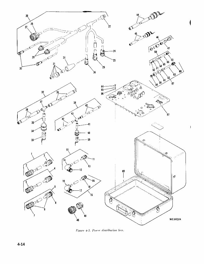
Figure 4-3.
4-14
KEY to fig. 4-3:
1. Cable assembly2. Connector3. Connector4. Gable assembly5. Connector6. Cable assembly7. Connector8. Connector9. Cable adapter
10. Cable assembly11. Connector12. Connector13. Cable adapter14. Cable adapter15. Cable assembly16. Connector17. Connector18. Cable adapter19. Cable adapter20. Cable assembly21. Push switch22. Connector23. Connector24. Cable clamp25. Connector26. Connector27. Connector28. Cable adapter29. Connector30. Connector31. Boot32. Hose assembly33. Dust plug
4-12. Cleaning, Inspection and Repair.a. Cleaning. Refer to TM 9-247 and Section IV
of this chapter for general cleaning instructions.b. Inspection and Repair.
(1) Refer to section IV of this chapter forgeneral inspection and repair instructions.
(2) Repair dents in access doors (21, 49, 104,and 106, fig. 4-1).
(3) Test cables (29, 30, and 33, fig. 4-1) forcontinuity. Replace shorted or broken wires andwires with damaged insulation.
(4) Replace illegible identification andinstruction plates.
(5) Check fluid flow indicator (29, fig. 4-2)against test equipment that includes a calibratedflow meter.
34. Coupling half35. Tube assembly36. Hose assembly37. Tube tee38. Hose assembly39. Dust plug40. Coupling half41. Tube assembly42. Hose assembly43. Tube tee44. Hose assembly45. Hose assembly46. Straight adapter47. Tube assembly48. Connector49. Loop clamp50. Tube assembly51. Tube nut52. Clinch sleeve53. Tube nipple54. Coupling nut55. Sleeve56. Tube57. Tube assembly58. Tube nut59. Clinch sleeve60. Union61. Coupling nut62. Sleeve63. Tube64. Cap screw65. Lock washer66. Flat washer67. Instrument panel assembly68. Case assembly
(6) The accuracy of fluid level indicator (35,fig. 4-2) may be checked by draining the fluidreservoir and adding measured predeterminedamount of fluid to the reservoir and” observing theindicator. Replace defective indicator.
(7) Refer to TM 11-6140-203-15-2 for fieldmaintenance of the storage battery.4-13. Installation.
a. Refer to figure 4-3 and assemble powerdistribution box in reverse order of disassembly.
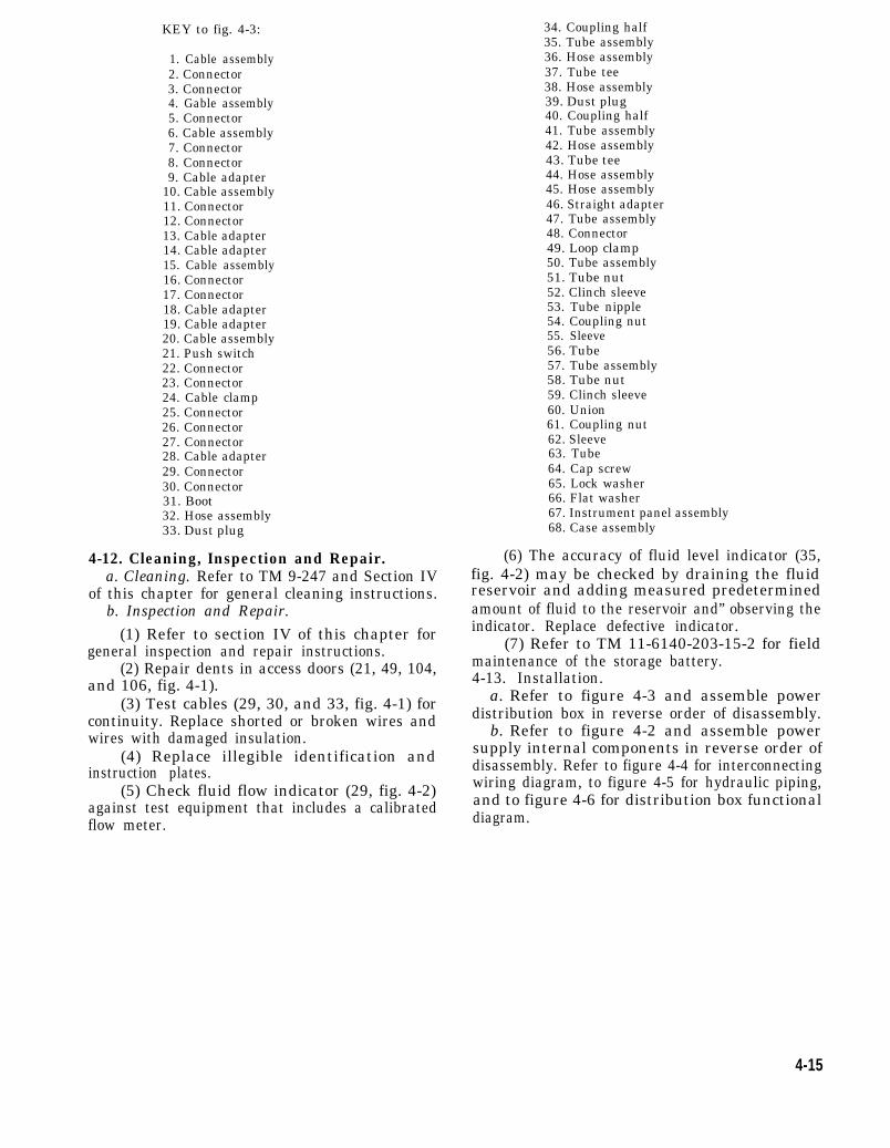
b. Refer to figure 4-2 and assemble powersupply internal components in reverse order ofdisassembly. Refer to figure 4-4 for interconnectingwiring diagram, to figure 4-5 for hydraulic piping,and to figure 4-6 for distribution box functionaldiagram.
4-15
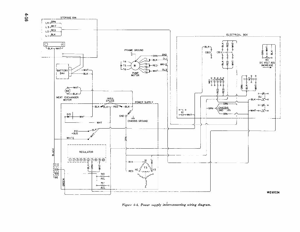
Figure 4-4.
4-16
Figure 4-5.
4-17

c. Refer to figure 4-1 and assemble power supply d. Refer to chapter 6 for checkout andexternal components in the reverse order of adjustment procedures of the power supply afterdisassembly. assembly.
4-18
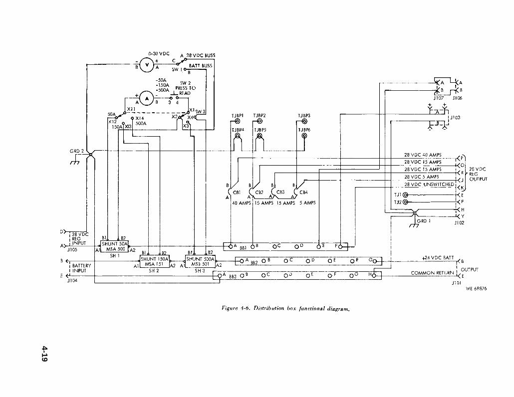
Figure 4-6.
4-19

CHAPTER 5
REPAIR OF POWER SUPPLY
Section I. REPAIR OF ELECTRICAL BOX ASSEMBLY
5-1. General. d. General cleaning, inspection, repair anda. Refer to chapter 4 for removal of electrical replacement instructions are contained in chapter
box assembly (13, fig. 4-2) from power supply. 4. Any specific instructions are noted in these repairb. The order of disassembly is in accordance procedures.
with illustration index number sequence of the 5-2. Disassembly.referenced illustrations. a. Refer to figure 5-1 and disassemble electrical
c. Assembly is in reverse order of disassembly box.sequence unless otherwise indicated. b. Refer to figure 5-2 and disassemble electrical
panel assembly (31, fig. 5-1).
5-1
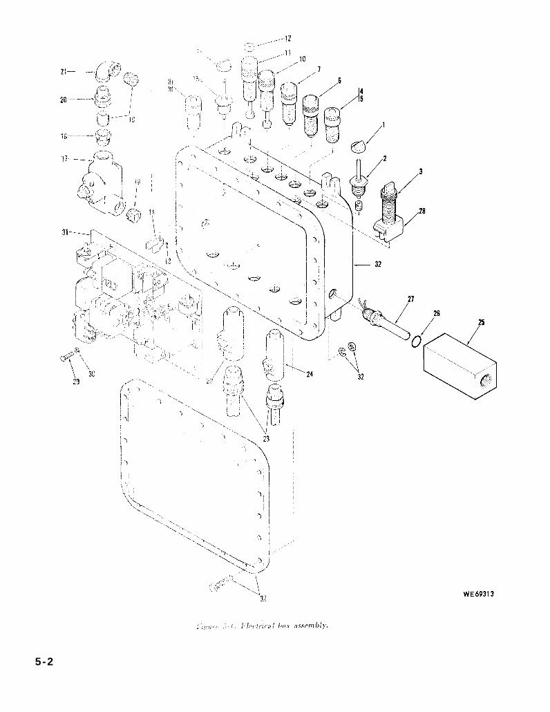
Figure 5-1.
5-2
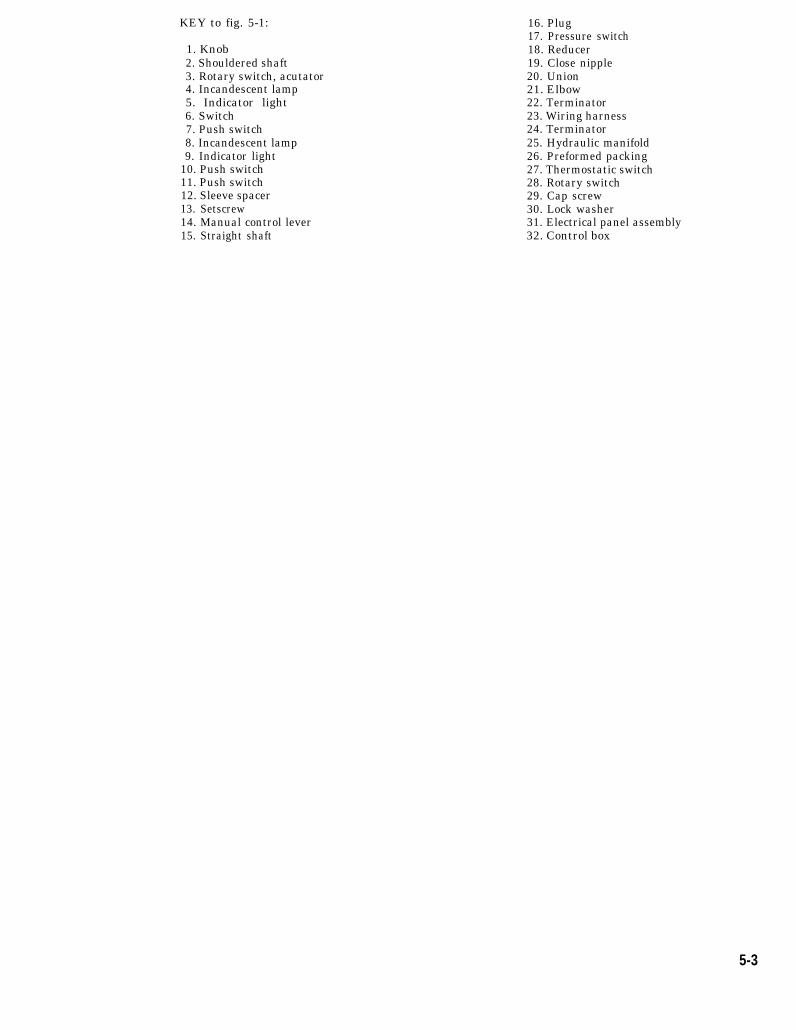
KEY to fig. 5-1:
1. Knob2. Shouldered shaft3. Rotary switch, acutator4. Incandescent lamp5. Indicator light6. Switch7. Push switch8. Incandescent lamp9. Indicator light
10. Push switch11. Push switch12. Sleeve spacer13. Setscrew14. Manual control lever15. Straight shaft
16. Plug17. Pressure switch18. Reducer19. Close nipple20. Union21. Elbow22. Terminator23. Wiring harness24. Terminator25. Hydraulic manifold26. Preformed packing27. Thermostatic switch28. Rotary switch29. Cap screw30. Lock washer31. Electrical panel assembly32. Control box
5-3
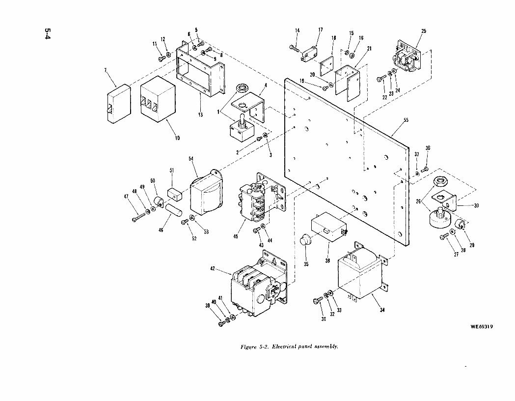
Figure 5-2.
5-4
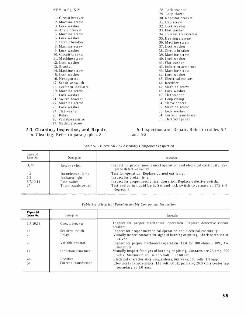
Figure 5-2
KEY to fig. 5-2:
1. Circuit breaker2. Machine screw3. Lock washer4. Angle bracket5. Machine screw6. Lock washer7. Circuit breaker8. Machine screw9. Lock washer
10. Circuit breaker11. Machine screw12. Lock washer13. Bracket14. Machine screw15. Lock washer16. Hexagon nut17. Sensitive switch18. Feedthru insulator19. Machine screw20. Lock washer21. Switch bracket22. Machine screw23. Lock washer24. Flat washer25. Relay26. Variable resistor27. Machine screw
5-3. Cleaning, Inspection, and Repair. a. Cleaning. Refer to paragraph 4-8.
28. Lock washer29. Loop clamp30. Rheostat bracket31. Cap screw32. Lock washer33. Flat washer34. Current transformer35. Heating element36. Machine screw37. Lock washer38. Circuit breaker39. Machine screw40. Lock washer41. Flat washer42. Induction armature43. Machine screw44. Lock washer45. Electrical contact46. Rectifier47. Machine screw48. Lock washer49. Flat washer50. Loop clamp51. Sleeve spacer52. Machine screw53. Lock washer54. Current transformer55. Electrical panel
b. Inspection and Repair. Refer to tables 5-1and 5-2.
Table 5-1. Electrical Box Assembly Component Inspection
Figure 5-1Index No. Description Inspection
3,28
4,85,96,7,10,1127
Rotary switch
Incandescent lampIndicator lightPush switchThermostatic switch
Inspect for proper mechanical operation and electrical continuity. Re-place defective switch.
Test for operation. Replace burned out lamp.Inspect for broken lens.Inspect for proper mechanical operation. Replace defective switch.Test switch in liquid bath. Set and lock switch to actuate at 175 ± 4
degrees F.
1,7,10,38
1725
26
42
4654
Table 5-2. Electrical Panel Assembly Component Inspection
Description
Circuit breaker
Sensitive switchRelay
Variable resistor
Induction armature
RectifierCurrent transformer
Inspection
Inspect for proper mechanical operation. Replace defective circuitbreakers.Inspect for proper mechanical operation and electrical continuity.Visually inspect contacts for signs of burning or pitting. Check operation at
24 vdc.Inspect for proper mechanical operation. Test for 100 ohms ± 10%, 3W
maximum.Visually inspect for signs of burning or pitting. Contacts are 25 amp, 600
volts. Maximum coil is 115 volt, 50 / 60 Hz.Electrical characteristics: single phase, full wave, 100 volts, 1.8 amp.Electrical characteristics: 115 volt, 60 Hz primary; 26.8 volts center tap
secondary at 1.0 amp.
5-5
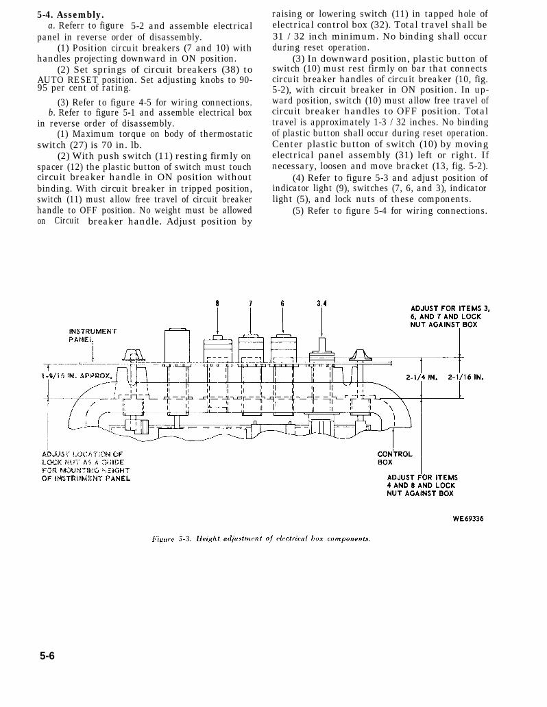
Figure 5-3.
5-4. Assembly.a. Referr to figure 5-2 and assemble electrical
panel in reverse order of disassembly.(1) Position circuit breakers (7 and 10) with
handles projecting downward in ON position.(2) Set springs of circuit breakers (38) to
AUTO RESET position. Set adjusting knobs to 90-95 per cent of rating.
(3) Refer to figure 4-5 for wiring connections.b. Refer to figure 5-1 and assemble electrical box
in reverse order of disassembly.(1) Maximum torque on body of thermostatic
switch (27) is 70 in. lb.(2) With push switch (11) resting firmly on
spacer (12) the plastic button of switch must touchcircuit breaker handle in ON position withoutbinding. With circuit breaker in tripped position,switch (11) must allow free travel of circuit breakerhandle to OFF position. No weight must be allowedon Circuit breaker handle. Adjust position by
raising or lowering switch (11) in tapped hole ofelectrical control box (32). Total travel shall be31 / 32 inch minimum. No binding shall occurduring reset operation.
(3) In downward position, plastic button ofswitch (10) must rest firmly on bar that connectscircuit breaker handles of circuit breaker (10, fig.5-2), with circuit breaker in ON position. In up-ward position, switch (10) must allow free travel ofcircuit breaker handles to OFF position. Totaltravel is approximately 1-3 / 32 inches. No bindingof plastic button shall occur during reset operation.Center plastic button of switch (10) by movingelectrical panel assembly (31) left or right. Ifnecessary, loosen and move bracket (13, fig. 5-2).
(4) Refer to figure 5-3 and adjust position ofindicator light (9), switches (7, 6, and 3), indicatorlight (5), and lock nuts of these components.
(5) Refer to figure 5-4 for wiring connections.
5-6
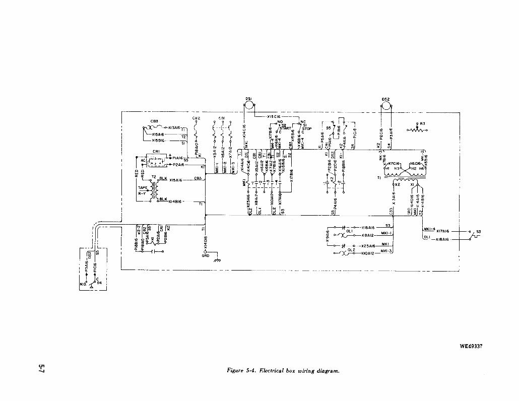
Figure 5-4.
5-7
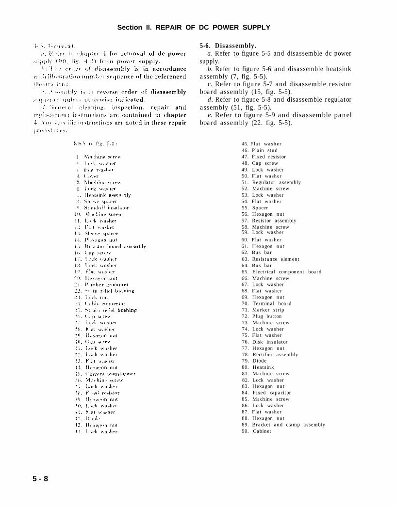
fig. 5-5:
5-5.
chapter 4
fig. 4-2
Section Il. REPAIR OF DC POWER SUPPLY
12.
3.
4.5.().
5-6. Disassembly.a. Refer to figure 5-5 and disassemble dc power
supply.b. Refer to figure 5-6 and disassemble heatsink
assembly (7, fig. 5-5).c. Refer to figure 5-7 and disassemble resistor
board assembly (15, fig. 5-5).d. Refer to figure 5-8 and disassemble regulator
assembly (51, fig. 5-5).e. Refer to figure 5-9 and disassemble panel
board assembly (22. fig. 5-5).
45. Flat washer46. Plain stud47. Fixed resistor48. Cap screw49. Lock washer50. Flat washer51. Regulator assembly52. Machine screw53. Lock washer54. Flat washer55. Spacer56. Hexagon nut57. Resistor assembly58. Machine screw59. Lock washer60. Flat washer61. Hexagon nut62. Bus bar63. Resistance element64. Bus bar65. Electrical component board66. Machine screw67. Lock washer68. Flat washer69. Hexagon nut70. Terminal board71. Marker strip72. Plug button73. Machine screw74. Lock washer75. Flat washer76. Disk insulator77. Hexagon nut78. Rectifier assembly79. Diode80. Heatsink81. Machine screw82. Lock washer83. Hexagon nut84. Fixed capacitor85. Machine screw86. Lock washer87. Flat washer88. Hexagon nut89. Bracket and clamp assembly90. Cabinet
5 - 8
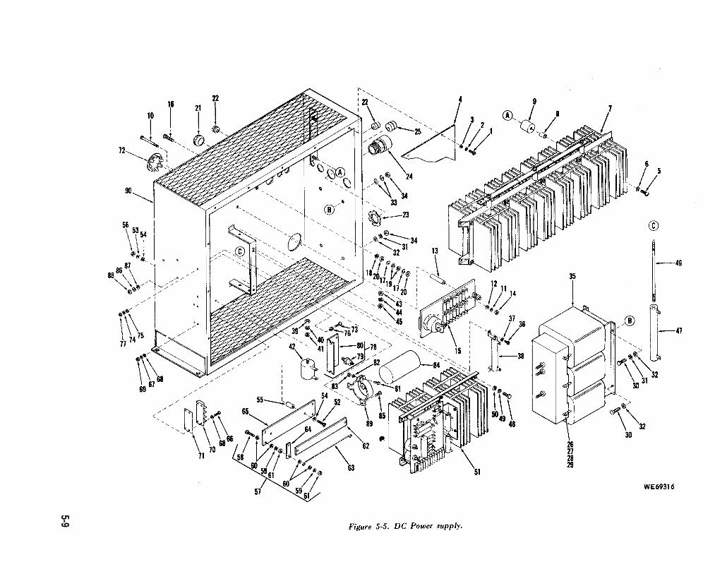
Figure 5-5.
5-9
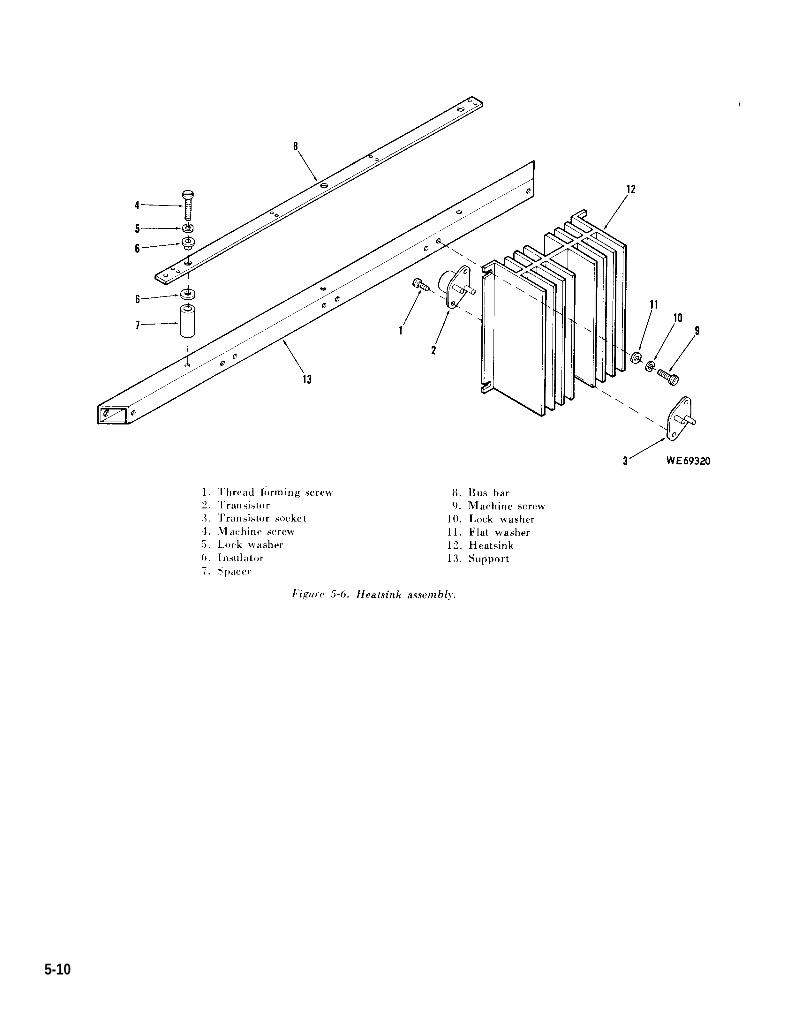
Figure 5-6.
5-10
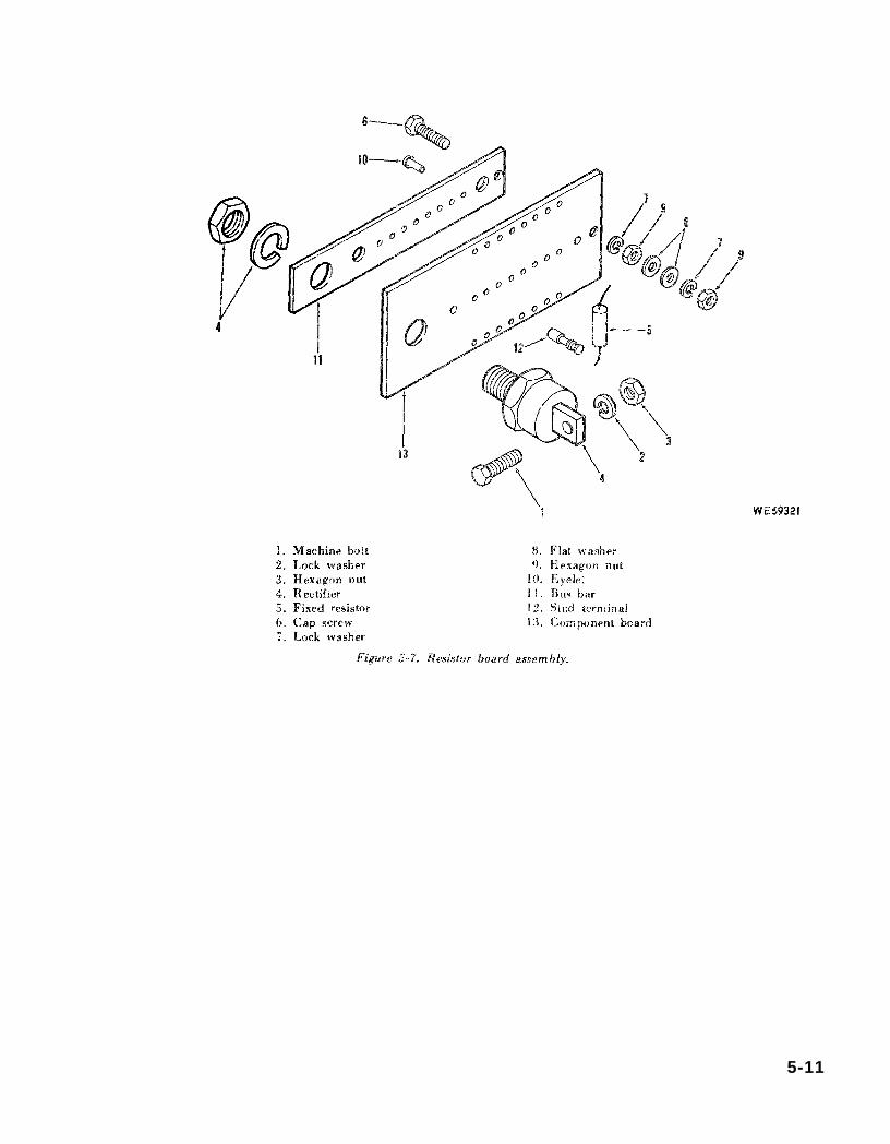
Figure 5-7.
5-11
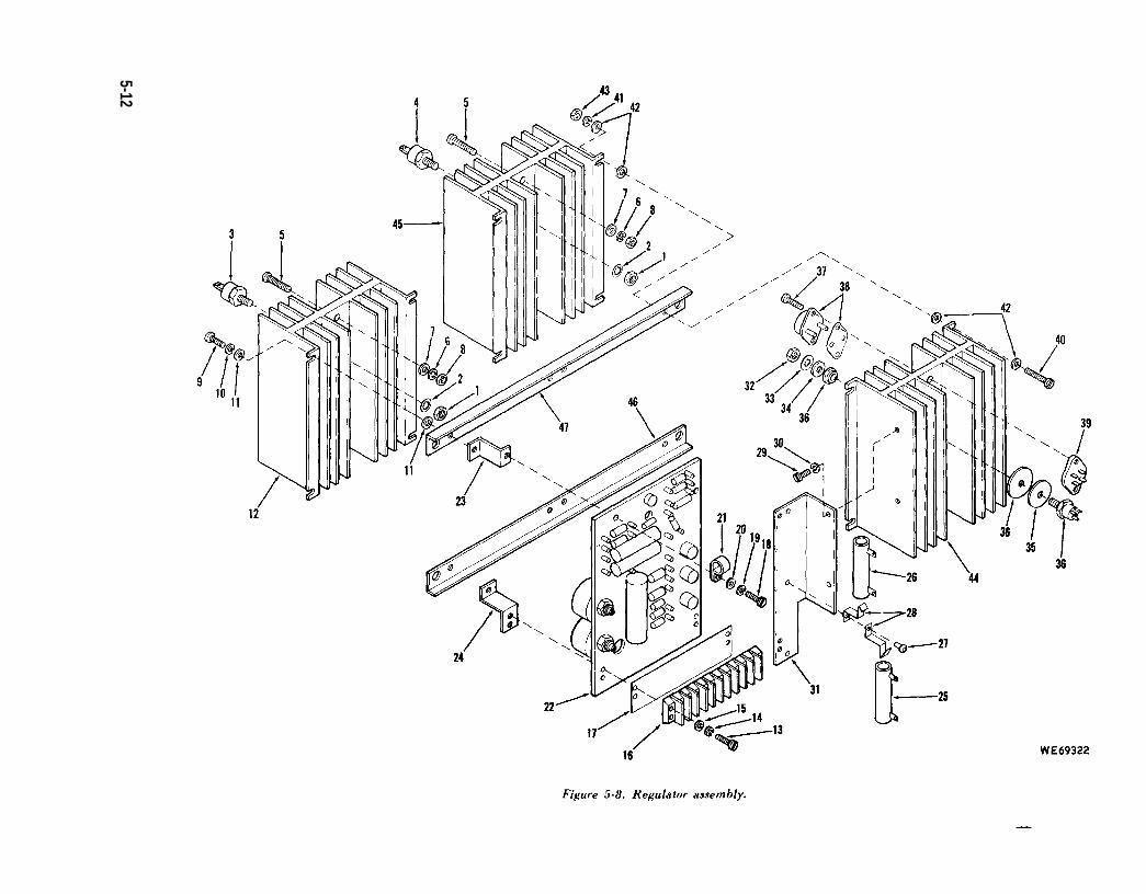
Figure 5-8.
5-12
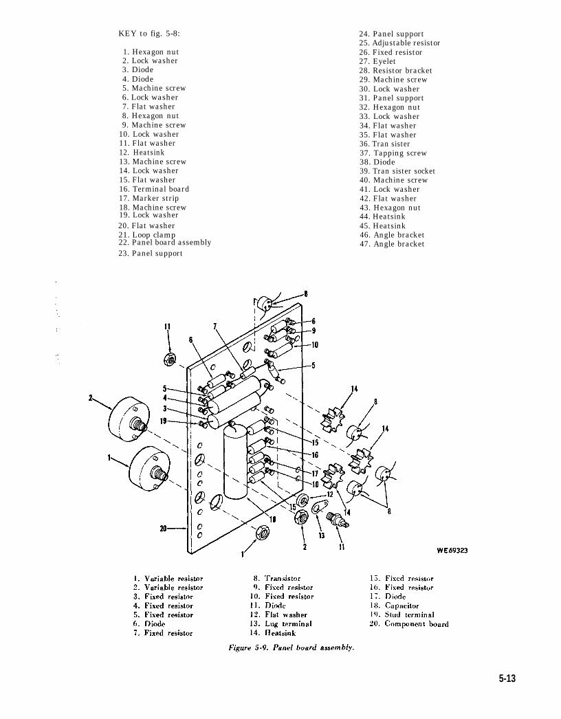
Figure 5-9.
KEY to fig. 5-8:
1. Hexagon nut2. Lock washer3. Diode4. Diode5. Machine screw6. Lock washer7. Flat washer8. Hexagon nut9. Machine screw
10. Lock washer11. Flat washer12. Heatsink13. Machine screw14. Lock washer15. Flat washer16. Terminal board
17. Marker strip18. Machine screw19. Lock washer20. Flat washer21. Loop clamp22. Panel board assembly23. Panel support
24. Panel support25. Adjustable resistor26. Fixed resistor27. Eyelet28. Resistor bracket29. Machine screw30. Lock washer31. Panel support32. Hexagon nut33. Lock washer34. Flat washer35. Flat washer36. Tran sister37. Tapping screw38. Diode39. Tran sister socket40. Machine screw41. Lock washer42. Flat washer43. Hexagon nut44. Heatsink45. Heatsink46. Angle bracket47. Angle bracket
5-13
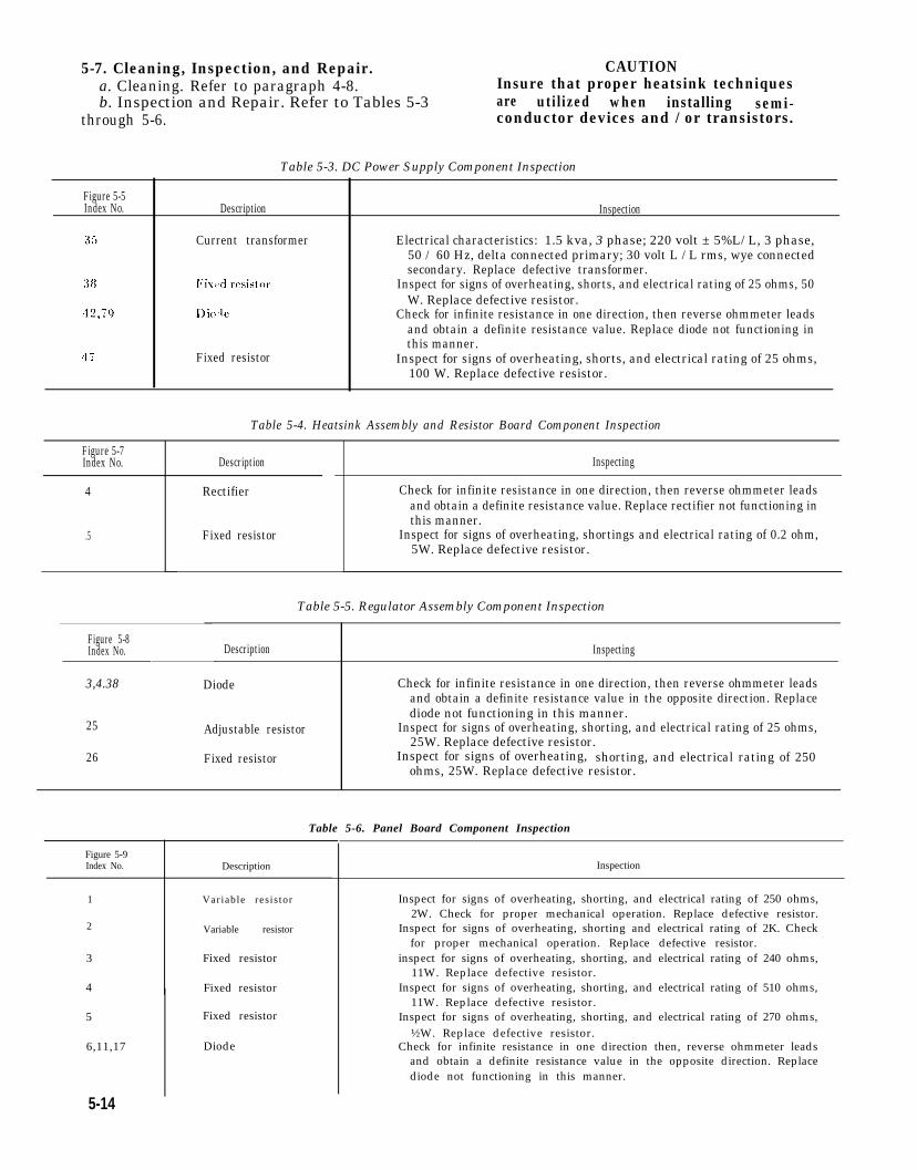
5-7. Cleaning, Inspection, and Repair. CAUTIONa. Cleaning. Refer to paragraph 4-8. Insure that proper heatsink techniquesb. Inspection and Repair. Refer to Tables 5-3 are utilized when installing
through 5-6.semi-
conductor devices and / or transistors.
Table 5-3. DC Power Supply Component Inspection
Figure 5-5Index No.
Figure 5-7Index No.
4
.5
Description
Current transformer
Fixed resistor
Inspection
Electrical characteristics: 1.5 kva, 3 phase; 220 volt ± 5%L/ L, 3 phase,50 / 60 Hz, delta connected primary; 30 volt L / L rms, wye connectedsecondary. Replace defective transformer.
Inspect for signs of overheating, shorts, and electrical rating of 25 ohms, 50W. Replace defective resistor.
Check for infinite resistance in one direction, then reverse ohmmeter leadsand obtain a definite resistance value. Replace diode not functioning inthis manner.
Inspect for signs of overheating, shorts, and electrical rating of 25 ohms,100 W. Replace defective resistor.
Table 5-4. Heatsink Assembly and Resistor Board Component Inspection
Description
Rectifier
Fixed resistor
Inspecting
Check for infinite resistance in one direction, then reverse ohmmeter leadsand obtain a definite resistance value. Replace rectifier not functioning inthis manner.
Inspect for signs of overheating, shortings and electrical rating of 0.2 ohm,5W. Replace defective resistor.
Table 5-5. Regulator Assembly Component Inspection
Figure 5-8Index No. Description Inspecting
3,4.38 Diode Check for infinite resistance in one direction, then reverse ohmmeter leadsand obtain a definite resistance value in the opposite direction. Replacediode not functioning in this manner.
25 Adjustable resistor Inspect for signs of overheating, shorting, and electrical rating of 25 ohms,25W. Replace defective resistor.
26 Fixed resistor Inspect for signs of overheating, shorting, and electrical rating of 250ohms, 25W. Replace defective resistor.
Figure 5-9Index No. Description
1 Variable res is tor
2 Variable resistor
3 Fixed resistor
4 Fixed resistor
5 Fixed resistor
6,11,17 Diode
Table 5-6. Panel Board Component Inspection
5-14
Inspection
Inspect for signs of overheating, shorting, and electrical rating of 250 ohms,2W. Check for proper mechanical operation. Replace defective resistor.
Inspect for signs of overheating, shorting and electrical rating of 2K. Checkfor proper mechanical operation. Replace defective resistor.
inspect for signs of overheating, shorting, and electrical rating of 240 ohms,11W. Replace defective resistor.
Inspect for signs of overheating, shorting, and electrical rating of 510 ohms,11W. Replace defective resistor.
Inspect for signs of overheating, shorting, and electrical rating of 270 ohms,½W. Replace defective resistor.
Check for infinite resistance in one direction then, reverse ohmmeter leadsand obtain a definite resistance value in the opposite direction. Replacediode not functioning in this manner.
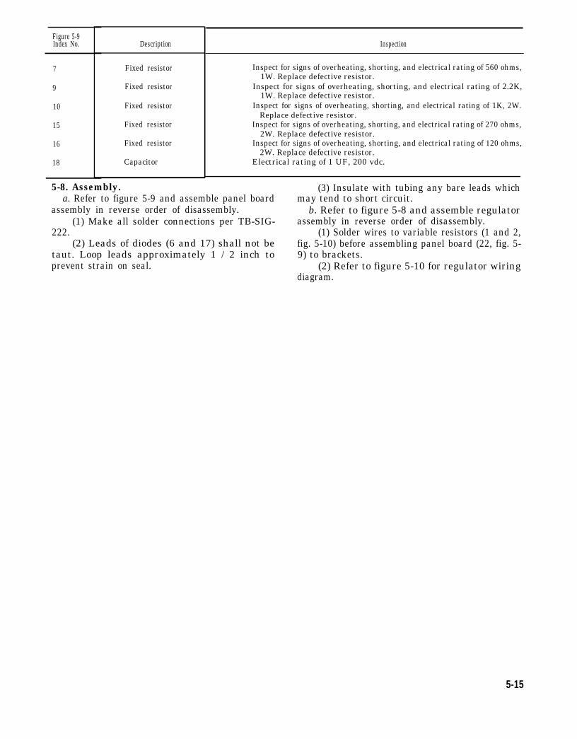
Figure 5-9Index No.
7
9
10
15
16
18
Description
Fixed resistor
Fixed resistor
Fixed resistor
Fixed resistor
Fixed resistor
Capacitor
5-8. Assembly.
Inspection
Inspect for signs of overheating, shorting, and electrical rating of 560 ohms,1W. Replace defective resistor.
Inspect for signs of overheating, shorting, and electrical rating of 2.2K,1W. Replace defective resistor.
Inspect for signs of overheating, shorting, and electrical rating of 1K, 2W.Replace defective resistor.
Inspect for signs of overheating, shorting, and electrical rating of 270 ohms,2W. Replace defective resistor.
Inspect for signs of overheating, shorting, and electrical rating of 120 ohms,2W. Replace defective resistor.
Electrical rating of 1 UF, 200 vdc.
(3) Insulate with tubing any bare leads whicha. Refer to figure 5-9 and assemble panel board
assembly in reverse order of disassembly.(1) Make all solder connections per TB-SIG-
222.(2) Leads of diodes (6 and 17) shall not be
taut. Loop leads approximately 1 / 2 inch toprevent strain on seal.
may tend to short circuit.b. Refer to figure 5-8 and assemble regulator
assembly in reverse order of disassembly.(1) Solder wires to variable resistors (1 and 2,
fig. 5-10) before assembling panel board (22, fig. 5-9) to brackets.
(2) Refer to figure 5-10 for regulator wiringdiagram.
5-15
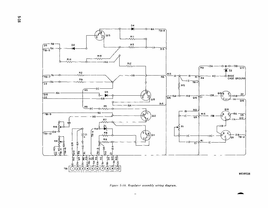
Figure 5-10.
5-16
c. Refer to figure 5-7 and assemble resistor e. Refer to figure 5-5 and assemble dc powerboard assembly in reverse order of disassembly. supply in reverse order of disassembly Refer toSolder resistors (5) to eyelets (10) and then solder figure FO-2 for wiring diagram. Refer to chapter 6eyelets and screws (6) to bus bar (11). for tests and adjustment of power supply after
d. Refer to figure 5-6 and assemble heatsink installation.assembly in reverse order of disassembly.
Section Ill. REPAIR OF INSTRUMENT PANEL ASSEMBLY
5-9. General. d. General cleaning, inspection, repair anda. Refer to chapter 4 for removal of instrument replacement instructions are contained in chapter
panel assembly (71. fig. 4-3) from distribution 4. Any specific instructions are noted in these repairpanel assembly. procedures.
b. The order of disassembly is in accordance 5-10. Disassembly.with illustration number sequence of the referenced Refer to figure 5-11 and disassemble theillustrations. instrument panel assembly.
c. Assembly is in reverse order of disassemblysequence unless otherwise indicated.
5-17
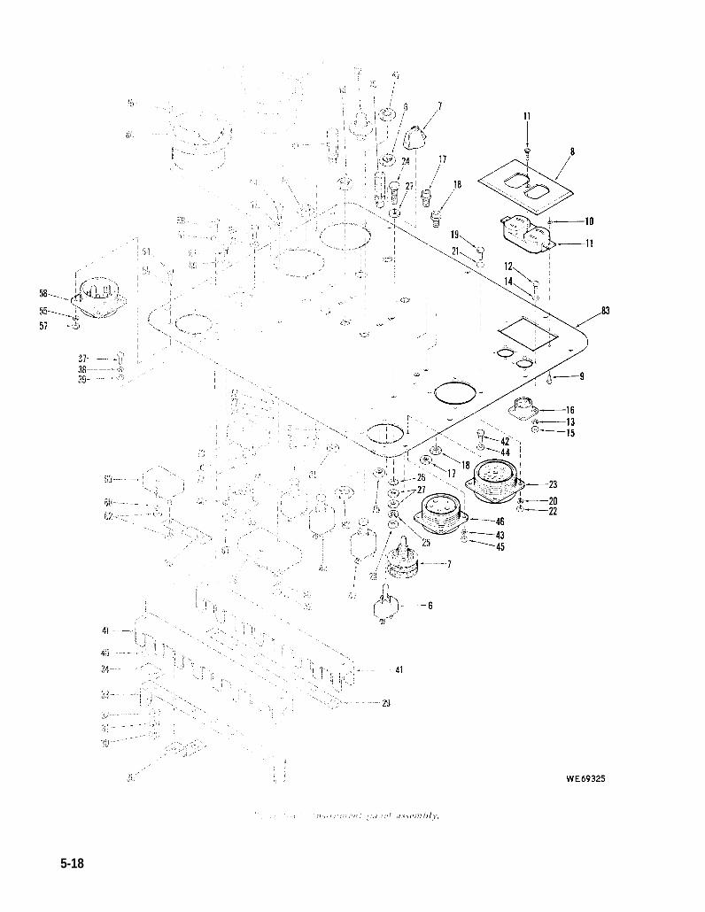
Figure 5-11.
5-18
KEY to fig. 5-11:
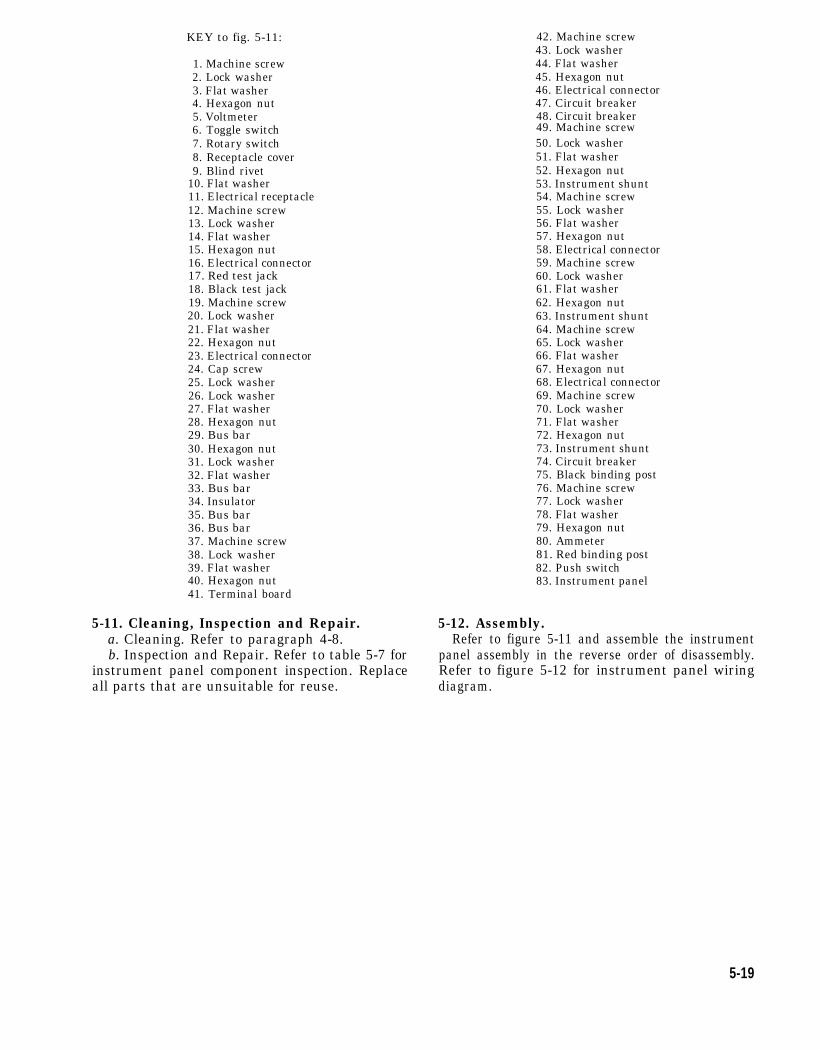
1. Machine screw2. Lock washer3. Flat washer4. Hexagon nut5. Voltmeter6. Toggle switch7. Rotary switch8. Receptacle cover9. Blind rivet
10. Flat washer11. Electrical receptacle12. Machine screw13. Lock washer14. Flat washer15. Hexagon nut16. Electrical connector17. Red test jack18. Black test jack19. Machine screw20. Lock washer21. Flat washer22. Hexagon nut23. Electrical connector24. Cap screw25. Lock washer26. Lock washer27. Flat washer28. Hexagon nut29. Bus bar30. Hexagon nut31. Lock washer32. Flat washer33. Bus bar34. Insulator35. Bus bar36. Bus bar37. Machine screw38. Lock washer39. Flat washer40. Hexagon nut41. Terminal board
5-11. Cleaning, Inspection and Repair.a. Cleaning. Refer to paragraph 4-8.b. Inspection and Repair. Refer to table 5-7 for
instrument panel component inspection. Replaceall parts that are unsuitable for reuse.
42. Machine screw43. Lock washer44. Flat washer45. Hexagon nut46. Electrical connector47. Circuit breaker48. Circuit breaker49. Machine screw50. Lock washer51. Flat washer52. Hexagon nut53. Instrument shunt54. Machine screw55. Lock washer56. Flat washer57. Hexagon nut58. Electrical connector59. Machine screw60. Lock washer61. Flat washer62. Hexagon nut63. Instrument shunt64. Machine screw65. Lock washer66. Flat washer67. Hexagon nut68. Electrical connector69. Machine screw70. Lock washer71. Flat washer72. Hexagon nut73. Instrument shunt74. Circuit breaker75. Black binding post76. Machine screw77. Lock washer78. Flat washer79. Hexagon nut80. Ammeter81. Red binding post82. Push switch83. Instrument panel
5-12. Assembly.Refer to figure 5-11 and assemble the instrument
panel assembly in the reverse order of disassembly.Refer to figure 5-12 for instrument panel wiringdiagram.
5-19
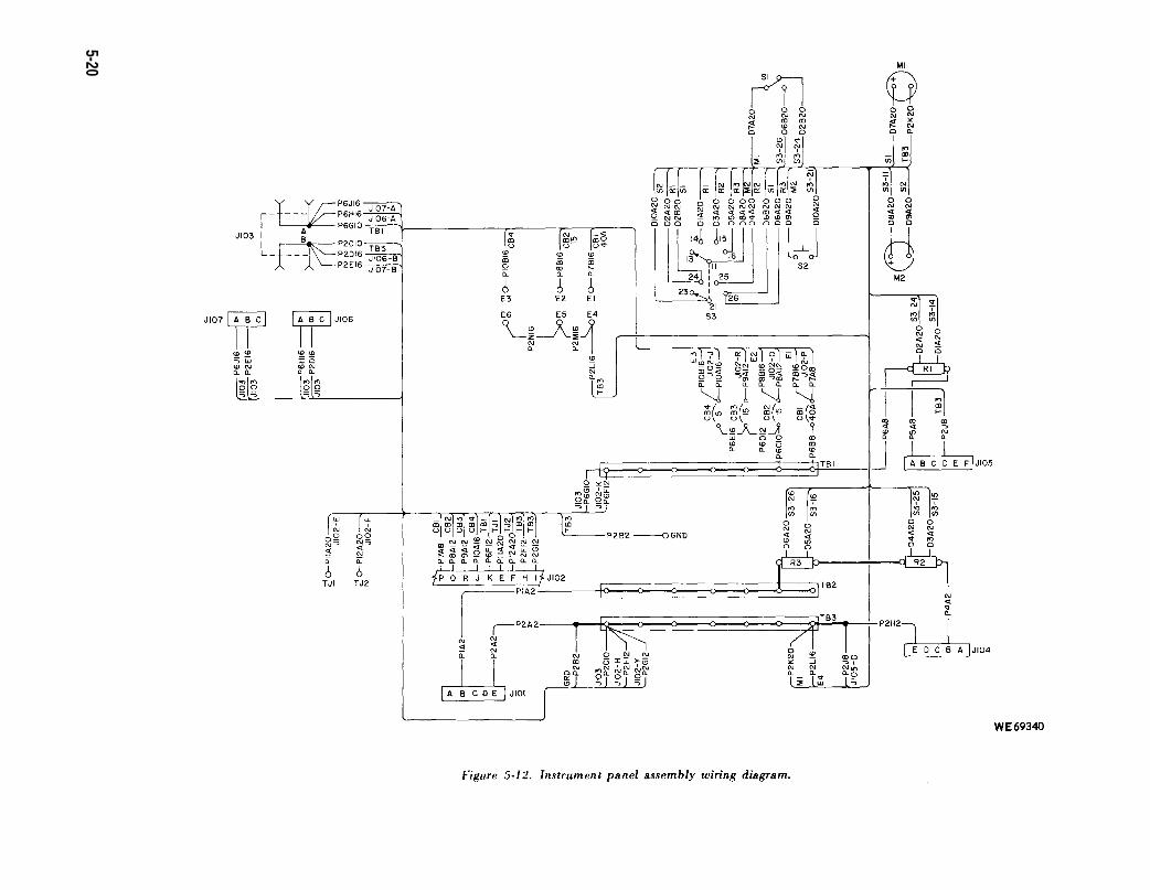
Figure 5-12.
5-20
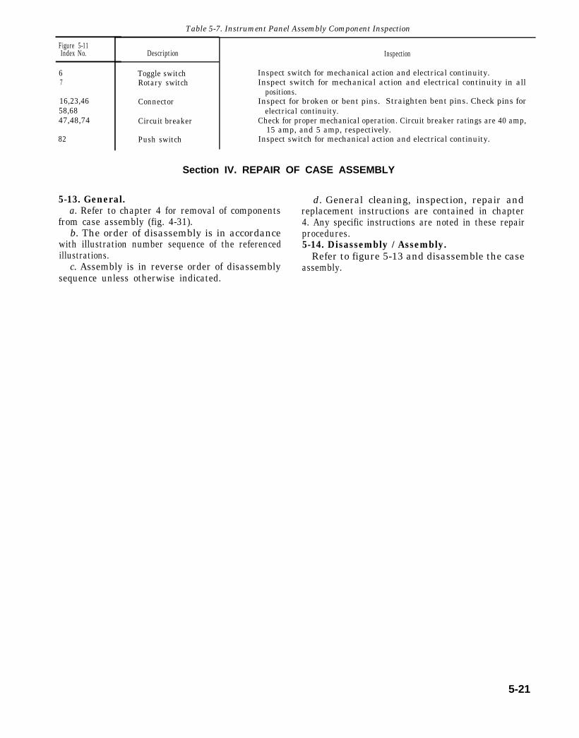
Table 5-7. Instrument Panel Assembly Component Inspection
Figure 5-11Index No.
67
16,23,4658,6847,48,74
82
Description
Toggle switchRotary switch
Connector
Circuit breaker
Push switch
Inspection
Inspect switch for mechanical action and electrical continuity.Inspect switch for mechanical action and electrical continuity in all
positions.Inspect for broken or bent pins. Straighten bent pins. Check pins for
electrical continuity.Check for proper mechanical operation. Circuit breaker ratings are 40 amp,
15 amp, and 5 amp, respectively.Inspect switch for mechanical action and electrical continuity.
Section IV. REPAIR OF CASE ASSEMBLY
5-13. General. d. General cleaning, inspection, repair anda. Refer to chapter 4 for removal of components replacement instructions are contained in chapter
from case assembly (fig. 4-31). 4. Any specific instructions are noted in these repairb. The order of disassembly is in accordance procedures.
with illustration number sequence of the referenced 5-14. Disassembly / Assembly.illustrations. Refer to figure 5-13 and disassemble the case
c. Assembly is in reverse order of disassembly assembly.sequence unless otherwise indicated.
5-21
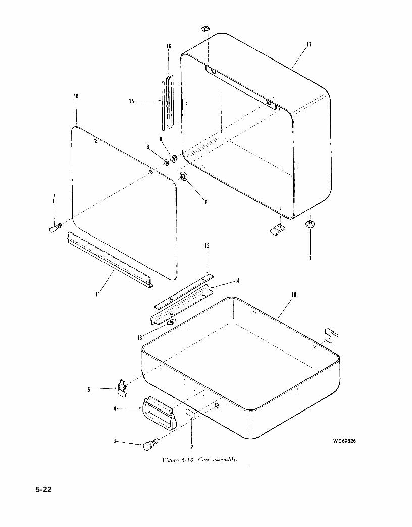
Figure 5-13.
5-22

KEY to fig. 5-13:
1. Foot2. Instruction plate3. Manual valve4. Handle5. Latch6. Retainer7. Stud8. Nut9. Receptacle
10. Inner lid11. Hinge12. Sealing frame13. Anchor nut14. Sealing gasket15. Sealing frame16. Sealing gasket17. Cover18. Case
5-23

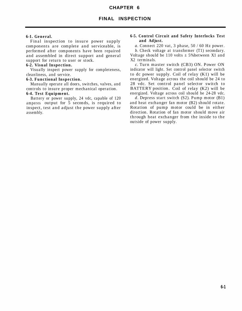
CHAPTER 6
FINAL INSPECTION
6-1. General.Final inspection to insure power supply
components are complete and serviceable, isperformed after components have been repairedand assembled in direct support and generalsupport for return to user or stock.6-2. Visual Inspection.
Visually inspect power supply for completeness,cleanliness, and service.6-3. Functional Inspection.
Manually operate all doors, switches, valves, andcontrols to insure proper mechanical operation.6-4. Test Equipment.
Battery or power supply, 24 vdc, capable of 120amperes output for 5 seconds, is required toinspect, test and adjust the power supply afterassembly.
6-5. Control Circuit and Safety Interlocks Testand Adjust.
a. Connect 220 vat, 3 phase, 50 / 60 Hz power.b. Check voltage at transformer (T1) secondary.
Voltage should be 110 volts ± 5%between X1 andX2 terminals.
c. Turn master switch (CB3) ON. Power ONindicator will light. Set control panel selector switchto dc power supply. Coil of relay (K1) will beenergized. Voltage across the coil should be 24 to28 vdc. Set control panel selector switch toBATTERY position. Coil of relay (K2) will beenergized. Voltage across coil should be 24-28 vdc.
d. Depress start switch (S2). Pump motor (B1)and heat exchanger fan motor (B2) should rotate.Rotation of pump motor could be in eitherdirection. Rotation of fan motor should move airthrough heat exchanger from the inside to theoutside of power supply.
6-1


CHAPTER 7
ADMINISTRATIVE STORAGE
Refer to TM 740-90-1 for administrative storage of the power supply.
7-1

APPENDIX AREFERENCES
1. Publication INDEXES.Consult each new issue of the following for the latest changes or revisions to
publications listed in this appendix or for new publications on the subsystem coveredin this technical manual.Index of Administrative Publications . . . . . . . . . . . . . . . . . . . . . DA Pam 310-1Index of Blank Forms . . . . . . . . . . . . . . . . . . . . . . . . . . . . . . . . . . . . . . . DA Pam 310-2Index of Doctrinal, Training, and organizational Publications . . . DA Pam 310-3Index of Supply Catalogs and Supply Manuals . . . . . . . . . . . . . . . . . . . . . DA Pam 310-6Index of Technical Manuals, Technical Bulletins, Supply Manuals
(types 7, 8, and 9) Supply Bulletins, and Lubrication orders. . . . . . . DA Pam 310-4U.S. Army Equipment Index of Modification Work Orders . . . . . . . . DA Pam 310-7
2. Forms.In addition to forms required by the Army Maintenance Management System
(TM 38-750), the following forms pertain to this materiel:Materiel Inspection Tag . . . . . . . . . . . . . . . . . . . . . . . . . . . . . . . . . . . . .. DA Form 9-1Recommended Changes to Publications . . . . . . . . . . . . . . . . DA Form 2028Report of Packaging and Handling Deficiencies . . . . . . . . . . . . DD Form 6Request for Issue or Turn-In . . . . . . . . . . . . . . . . . . . . . . . . . . . . . . . . . . DA Form 2765Requirements for Army Aviation and Army Avionic
Configuration Publications.. . . . . . . . . . . . . . . . . . . . . . . . . . . . . . . DA Form12-31Requisition for Publications and Bland Forms . . . . . . . . . . . . . . . . . . DA Form 173. Other Publications.
The following publications contain information pertinent to this materiel andassociated equipment:
a. Camouflage.Camouflage . . . . . . . . . . . . . . . . . . . . . . . . . . . . . . . . . . . . . . . . . . . . . . . . . FM 5-20
b. Decontamination.Chemical, Biological, and Radiological (C13R) Decontamination TM 3-220Chemical, Biological, Radiological and Nuclear Defense . . . . . . . . . FM 21-40
c. Destruction to Prevent Enemy Use.Explosives and Demolitions . . . . . . . . . . . . . . . . . . . . . . . . . . . . . . . . . FM 5-25Procedues for Destruction of Equipment toPrevent Enemy Use . . TM 750-244-7
d. General.Accident Reporting and Records . . . . . . . . . . . . . . . . . . . . . . . . . . . . . . AR385-40Army Maintenance Management System (TAMMS) . . . . . . . . . . . . TM 38-750Basic Cold Weather Manual . . . . . . . . . . . . . . . . . . . . . . . . . . . . . . . .. FM 31-70Protective Clothing and Equipment . . . . . . . . . . . . . . . . . . . AR 385-32
e. Maintenance and Repair.Cleaning of Ordnance Materiel . . . . . . . . . . . . . . . . . . . . . . . . . . . . . TM 9-208-1Direct Support and General Support, Repair Parts and
Special Tools List ( Including Depot Maintenanceand Special Tools) for Portable Hydraulic / ElectricPower Supply (4933-933-4742) . . . . . . . . . . . . . . . . . . . . . . TM 9-4933-211-34P
Maintenance Assistance and Instruction Team (MAIT) Program . . . . AR 750-51Materials Used for Cleaning, Preserving, Abrading and
Cementing Ordnance Materiel; and RelatedMaterials Including Chemicals . . . . . . . . . . . . . . . . . . . . . . . . . . . . . . . TM 9-247
Operator, Organizational, DS, GS and Depot Maintenance Manual,Including Repair Parts and Special Tools List:Aircraft Nickel Cadmium Battery, Storage BB433A . . . . . . . . . . TM 11-6140-203-15-2
Solder and Soldering . . . . . . . . . . . . . . . . . . . . . . . . . . . . . . . . . . . . . . . . TB-SIG-222
A-1
A-2
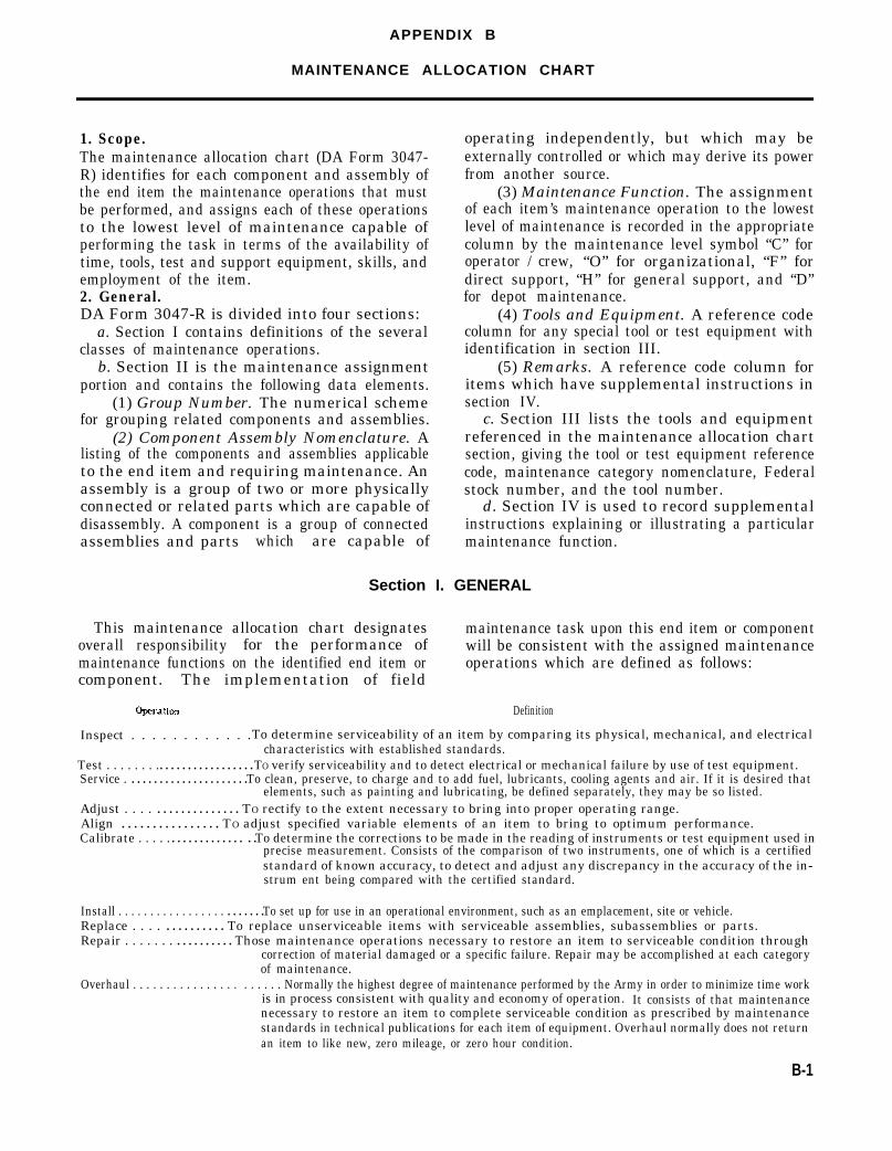
APPENDIX B
MAINTENANCE ALLOCATION CHART
1. Scope.The maintenance allocation chart (DA Form 3047-R) identifies for each component and assembly ofthe end item the maintenance operations that mustbe performed, and assigns each of these operationsto the lowest level of maintenance capable ofperforming the task in terms of the availability oftime, tools, test and support equipment, skills, andemployment of the item.2. General.DA Form 3047-R is divided into four sections:
a. Section I contains definitions of the severalclasses of maintenance operations.
b. Section II is the maintenance assignmentportion and contains the following data elements.
(1) Group Number. The numerical schemefor grouping related components and assemblies.
(2) Component Assembly Nomenclature. Alisting of the components and assemblies applicableto the end item and requiring maintenance. Anassembly is a group of two or more physicallyconnected or related parts which are capable ofdisassembly. A component is a group of connectedassemblies and parts which are capable of
This maintenance allocation chart designatesoverall responsibility for the performance ofmaintenance functions on the identified end item orcomponent. The implementation of field
operating independently, but which may beexternally controlled or which may derive its powerfrom another source.
(3) Maintenance Function. The assignmentof each item’s maintenance operation to the lowestlevel of maintenance is recorded in the appropriatecolumn by the maintenance level symbol “C” foroperator / crew, “O” for organizational, “F” fordirect support, “H” for general support, and “D”for depot maintenance.
(4) Tools and Equipment. A reference codecolumn for any special tool or test equipment withidentification in section III.
(5) Remarks. A reference code column foritems which have supplemental instructions insection IV.
c. Section III lists the tools and equipmentreferenced in the maintenance allocation chartsection, giving the tool or test equipment referencecode, maintenance category nomenclature, Federalstock number, and the tool number.
d. Section IV is used to record supplementalinstructions explaining or illustrating a particularmaintenance function.
Section I. GENERAL
maintenance task upon this end item or componentwill be consistent with the assigned maintenanceoperations which are defined as follows:
Definition
Inspect . . . . . . . . . . . .To determine serviceability of an item by comparing its physical, mechanical, and electricalcharacteristics with established standards.
Test . . . . . . . . . . . . . . . . . . . . . . . . . TO verify serviceability and to detect electrical or mechanical failure by use of test equipment. Service . . . . . . . . . . . . . . . . . . . . . . To clean, preserve, to charge and to add fuel, lubricants, cooling agents and air. If it is desired that
elements, such as painting and lubricating, be defined separately, they may be so listed.Adjust . . . . . . . . . . . . . . . . . . TO rectify to the extent necessary to bring into proper operating range. Align . . . . . . . . . . . . . . . . TO adjust specified variable elements of an item to bring to optimum performance. Calibrate . . . . . . . . . . . . . . . . . . . . To determine the corrections to be made in the reading of instruments or test equipment used in
precise measurement. Consists of the comparison of two instruments, one of which is a certifiedstandard of known accuracy, to detect and adjust any discrepancy in the accuracy of the in-strum ent being compared with the certified standard.
Install . . . . . . . . . . . . . . . . . . . . . . . . To set up for use in an operational environment, such as an emplacement, site or vehicle. Replace . . . . . . . . . . . . . . To replace unserviceable items with serviceable assemblies, subassemblies or parts. Repair . . . . . . . . . . . . . . . . . Those maintenance operations necessary to restore an item to serviceable condition through
correction of material damaged or a specific failure. Repair may be accomplished at each categoryof maintenance.
Overhaul . . . . . . . . . . . . . . . . . . . . . . Normally the highest degree of maintenance performed by the Army in order to minimize time workis in process consistent with quality and economy of operation. It consists of that maintenancenecessary to restore an item to complete serviceable condition as prescribed by maintenancestandards in technical publications for each item of equipment. Overhaul normally does not returnan item to like new, zero mileage, or zero hour condition.
B-1

Section I. GENERAL - Continued
Operation Definition
Rebuild . . . . . . . . . . . . . . . . . . .The highest degree of materiel maintenance. It consists of restoring equipment as nearly as possibleto new condition in accordance with original manufacturing standards. Rebuild is performed onlywhen required by operational considerations or other paramount factors and then only at the depotmaintenance category. Rebuild reduces to zero the hours or miles the equipment or componentthereof has been in use.
B-2
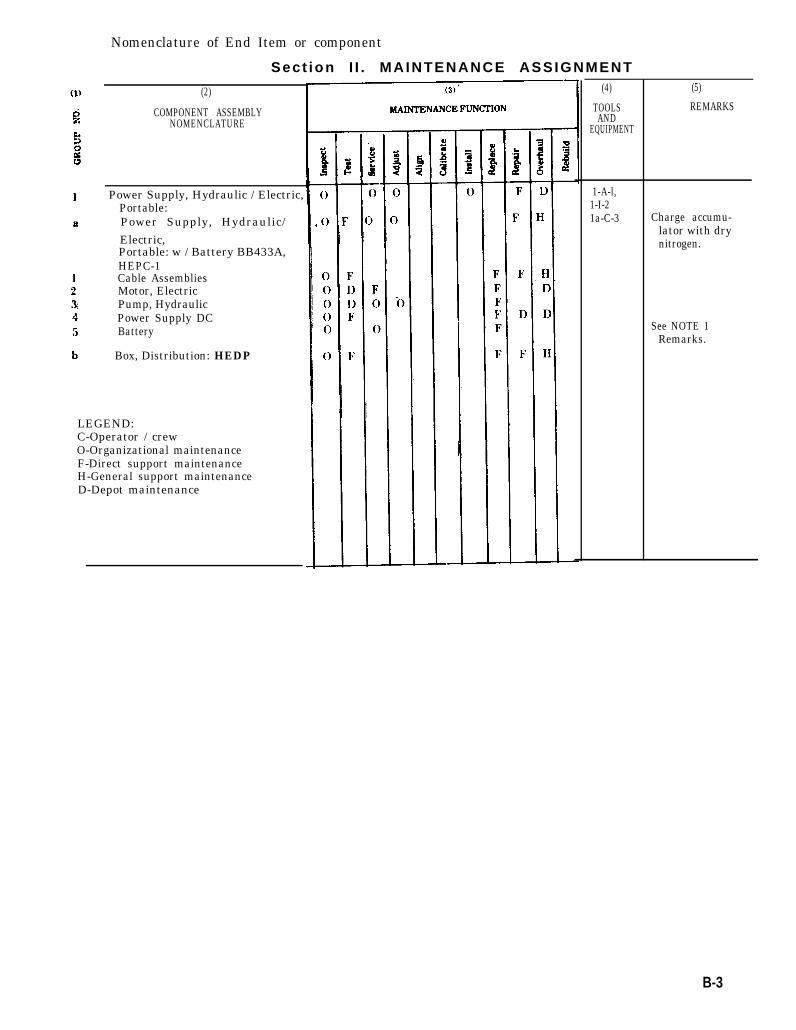
Nomenclature of End Item or component
Sect ion I I . MAINTENANCE ASSIGNMENT
(2)
COMPONENT ASSEMBLYNOMENCLATURE
Power Supply, Hydraulic / Electric,Portable:Power Supply, Hydraulic/Electric,Portable: w / Battery BB433A,HEPC-1Cable AssembliesMotor, ElectricPump, HydraulicPower Supply DCBattery
Box, Distribution: HEDP
LEGEND:C-Operator / crewO-Organizational maintenanceF-Direct support maintenanceH-General support maintenanceD-Depot maintenance
(4)
TOOLSAND
EQUIPMENT
1-A-l,1-I-21a-C-3
(5)
REMARKS
Charge accumu-lator with drynitrogen.
See NOTE 1Remarks.
B-3
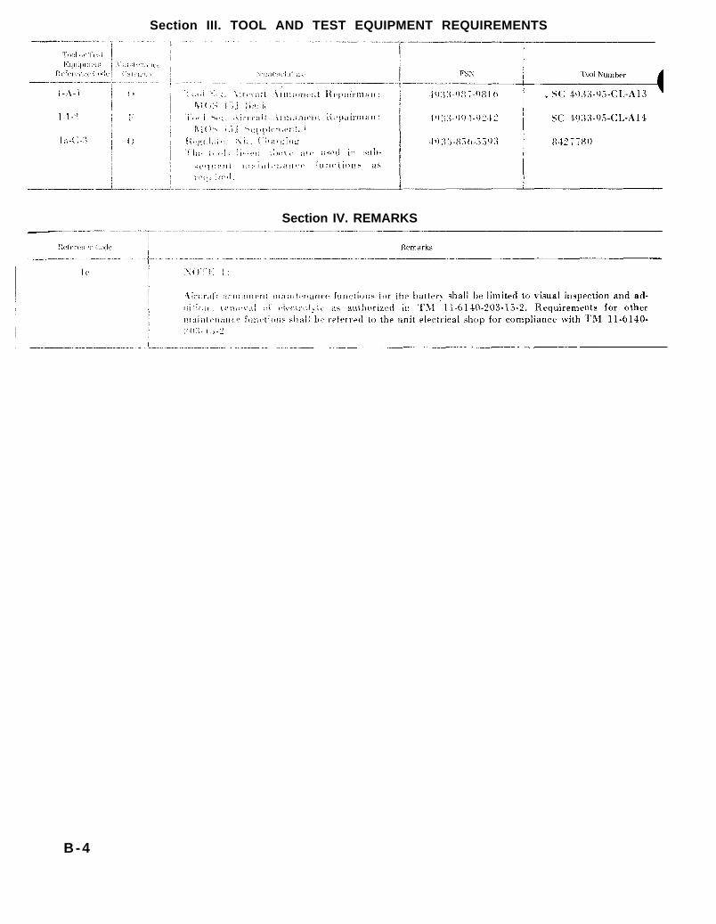
TM 11-6140-203-15-2
TM 11-6140-203-15-2
Section III. TOOL AND TEST EQUIPMENT REQUIREMENTS
Section IV. REMARKS
B-4

APPENDIX C
BASIC ISSUE ITEMS LIST
Not applicable.
C-1

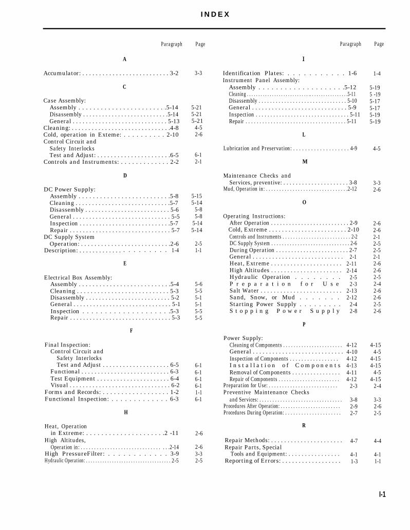
I N D E X
Paragraph
A
Accumulator: . . . . . . . . . . . . . . . . . . . . . . . . . . 3-2
C
Case Assembly:Assembly . . . . . . . . . . . . . . . . . . . . . . . .5-14Disassembly . . . . . . . . . . . . . . . . . . . . . . . . . . .5-14General . . . . . . . . . . . . . . . . . . . . . . . . . . . . . 5-13
Cleaning: . . . . . . . . . . . . . . . . . . . . . . . . . . . . . .4-8Cold, operation in Exteme: . . . . . . . . . . 2-10Control Circuit and
Safety InterlocksTest and Adjust: . . . . . . . . . . . . . . . . . . . . . .6-5
Controls and Instruments: . . . . . . . . . . . . . 2-2
D
DC Power Supply:Assembly . . . . . . . . . . . . . . . . . . . . . . . . . .5-8Cleaning . . . . . . . . . . . . . . . . . . . . . . . . . . . . .5-7Disassembly . . . . . . . . . . . . . . . . . . . . . . . . . . 5-6General . . . . . . . . . . . . . . . . . . . . . . . . . . . . . . 5-5Inspection . . . . . . . . . . . . . . . . . . . . . . . . . . . .5-7Repair . . . . . . . . . . . . . . . . . . . . . . . . . . . . . . . 5-7
DC Supply SystemOperation: . . . . . . . . . . . . . . . . . . . . . . . . . . .2-6
Description: . . . . . . . . . . . . . . . . . . . . . .
E
1-4
Electrical Box Assembly:Assembly . . . . . . . . . . . . . . . . . . . . . . . . . . .5-4Cleaning . . . . . . . . . . . . . . . . . . . . . . . . . . . 5-3Disassembly . . . . . . . . . . . . . . . . . . . . . . . . . . 5-2General . . . . . . . . . . . . . . . . . . . . . . . . . . . . . . 5-1Inspection . . . . . . . . . . . . . . . . . . . .5-3Repair . . . . . . . . . . . . . . . . . . . . . . . . . . . . . . . 5-3
F
Final Inspection:Control Circuit and
Safety InterlocksTest and Adjust . . . . . . . . . . . . . . . . . . . . 6-5
Functional . . . . . . . . . . . . . . . . . . . . . . . . . . . 6-3Test Equipment . . . . . . . . . . . . . . . . . . . . . . 6-4Visual . . . . . . . . . . . . . . . . . . . . . . . . . . . . . . . 6-2
Forms and Records: . . . . . . . . . . . . . . . . . . 1-2Functional Inspection: . . . . . . . . . . . . . 6-3
H
Heat, Operationin Extreme: . . . . . . . . . . . . . . . . . . . . .2 -11
High Altitudes,Operation in: . . . . . . . . . . . . . . . . . . . . . . . . . . . . . . . . .2-14
High PressureFilter: . . . . . . . . . . . . 3-9Hydraulic Operation: . . . . . . . . . . . . . . . . . . . . . . . . . . . . . . . . . . . . 2-5
Page
3-3
5-215-215-21
4-52-6
6-12-1
5-155-14
5-85-8
5-145-14
2-51-1
5-65-55-15-15-55-5
6-16-16-16-11-16-1
2-6
2-63-32-5
Paragraph
Identification Plates: . . . . . . . . . . . 1-6Instrument Panel Assembly:
Assembly . . . . . . . . . . . . . . . . . . . .5-12Cleaning . . . . . . . . . . . . . . . . . . . . . . . . . . . .. . . . . . . . . . . . . . . . .5-11Disassembly . . . . . . . . . . . . . . . . . . . . . . . . . . . . . . . 5-10General . . . . . . . . . . . . . . . . . . . . . . . . . . . . . 5-9Inspection . . . . . . . . . . . . . . . . . . . . . . . . . . . . . . . . 5-11Repair . . . . . . . . . . . . . . . . . . . . . . . . . . . . . . . . . . . . 5-11
L
Lubrication and Preservation: . . . . . . . . . . . . . . . . . . . 4-9
M
Maintenance Checks andServices, preventive: . . . . . . . . . . . . . . . . . . . . . 3-8
Mud, Operation in: . . . . . . . . . . . . . . . . . . . . . . . . . . . . . . .2-12
O
Operating Instructions:After Operation . . . . . . . . . . . . . . . . . . . . . . . . . . 2-9Cold, Extreme . . . . . . . . . . . . . . . . . . . . . . . . 2-10Controls and Instruments . . . . . . . . . . . . . . . . . . . . . . . . . . 2-2DC Supply System . . . . . . . . . . . . . . . . . . . . . . . . . . . . . . 2-6During Operation . . . . . . . . . . . . . . . . . . . . . . . . 2-7General . . . . . . . . . . . . . . . . . . . . . . . . . . . .Heat, Extreme . . . . . . . . . . . . . . . . . . . . . .High Altitudes . . . . . . . . . . . . . . . . . . . . . .Hydraulic Operation . . . . . . . .P r e p a r a t i o n f o r U s eSalt Water . . . . . . . . . . . . . . . . . . . . . . . . .Sand, Snow, or Mud . . . . . . .Starting Power Supply . . . . . . . . .S t o p p i n g P o w e r S u p p l y
P
Power Supply:Cleaning of Components . . . . . . . . . . . . . . . . . . . . . . .General . . . . . . . . . . . . . . . . . . . . . . . . . . . .Inspection of Components . . . . . . . . . . . . . . . . .I n s t a l l a t i o n o f C o m p o n e n t sRemoval of Components . . . . . . . . . . . . . . . .Repair of Components . . . . . . . . . . . . . . . . . . . . . . .
Preparation for Use: . . . . . . . . . . . . . . . . . . . . . . . . . . Preventive Maintenance Checks
and Services: . . . . . . . . . . . . . . . . . . . . . . . . . . . . . . . .Procedures After Operation: . . . . . . . . . . . . . . . . . . . . . . . . Procedures During Operation: . . . . . . . . . . . . . . . . . . . . .
R
Repair Methods: . . . . . . . . . . . . . . . . . . . . . .Repair Parts, Special
Tools and Equipment: . . . . . . . . . . . . . . . .Reporting of Errors: . . . . . . . . . . . . . . . . . .
2-12-112-14
2-52-3
2-132-12
2-42-8
4-124-104-124-134-114-12
2-3
3-82-92-7
4-7
4-11-3
Page
1-4
5-195 -195-175-175-195-19
4-5
3-32-6
2-62-62-12-52-52-12-62-62-52-42-62-62-52-6
4-154-5
4-154-15
4-54-15
2-4
3-32-62-5
4-4
4-11-1
I-1

lNDEX - Continued
Paragraph Page
T
Paragraph Page
Salt Water Areas,Operation in: . . . . . . . . . . . . . 2-13 2-6
Sand, Operation in: . . . . . . . . . . . . . . . . 2-12 2-6Scope: . . . . . . . . . . . 1-1 1-1Snow Operation in: . . . . . . . . . . 2-12 2-6Starating Power Supply: . . . . . . . . . . . . . . .2-4 2-5Stopping Power Supply: . . . . . . . . . . . . . . . . . 2-8 2-6
Tabulated Data: . . . . . . . . . . . . . . . 1-5 1-3Test Equipment: . . . . . . . . . . . . . . . . . . . . . . . .6-4 6-1Troubleshooting: . . . . . . . . . . . . . . . . . . . . . . . .4-2 4-1Troubleshooting Procedures: . . . . . . . . . . . . . . . . .4-3 4-2
V
Visual Inspection: . . . . . . . . . . . . . . 6-2 6-1
I-2
By Order of the Secretary of the Army:
W. C. WESTMORELAND,General, United States Army,Chief of Staff.Official:
VERNE L. BOWERS,Major General, United States Army,The Adjutant General.
DISTRIBUTION:
To be distributed in accordance with DA Form 12-31, Section IV, direct and general supportmaintenance requirements for 40-MM Grenade Launcher, M5; 7.62-MM Machine Gun, ArmamentPOD XM18 / XM18Al; Mount, Multi-Armament, Helicopter, XM156; 7.62-MM Machine Gun / 40-MM Grenade Launcher, XM28 / XM28E1; and 20-MM Automatic Gun, XM35, one (1)copy each account.

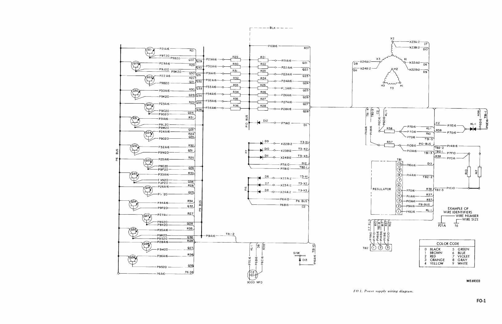
FO-1.
FO-1
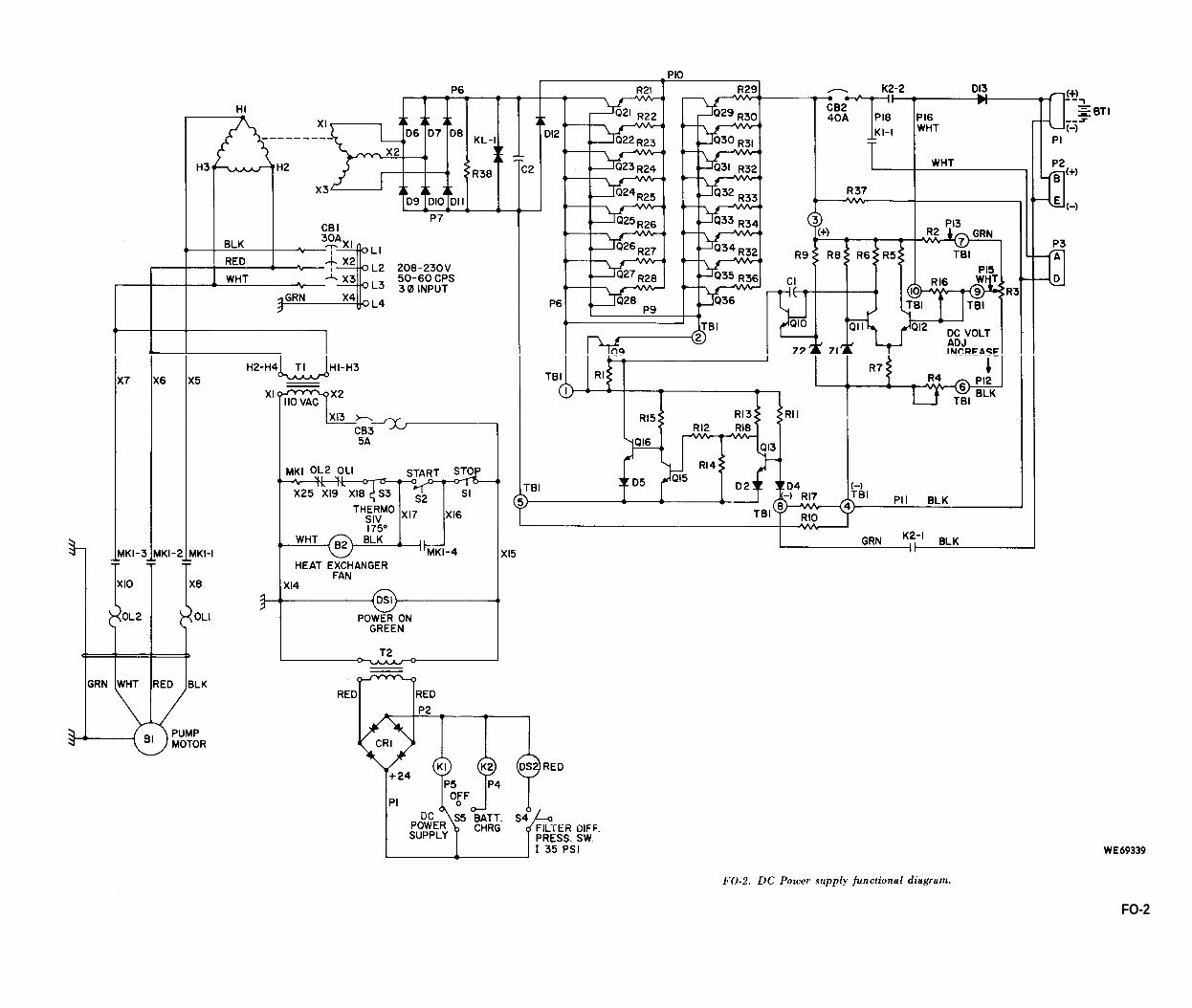
FO-2.
FO-2

TM
9-4
933-
211-
14

This fine document...
Was brought to you by me:
Liberated Manuals -- free army and government manuals
Why do I do it? I am tired of sleazy CD-ROM sellers, who take publicly available information, slap “watermarks” and other junk on it, and sell it. Those masters of search engine manipulation make sure that their sites that sell free information, come up first in search engines. They did not create it... They did not even scan it... Why should they get your money? Why are not letting you give those free manuals to your friends?
I am setting this document FREE. This document was made by the US Government and is NOT protected by Copyright. Feel free to share, republish, sell and so on.
I am not asking you for donations, fees or handouts. If you can, please provide a link to liberatedmanuals.com, so that free manuals come up first in search engines:
<A HREF=http://www.liberatedmanuals.com/>Free Military and Government Manuals</A>
– SincerelyIgor Chudovhttp://igor.chudov.com/
– Chicago Machinery Movers


![Topics in Website Testing [Reading assignment: Chapter 14, pp. 211-227]](https://img.pdfslide.net/doc/110x75/56649d965503460f94a7ec69/topics-in-website-testing-reading-assignment-chapter-14-pp-211-227.jpg)