Embed Size (px)
Citation preview
© B62-1228-20 (K,E,M)09 08 07 06 05 04 03 02 01
KENWOOD CORPORATION
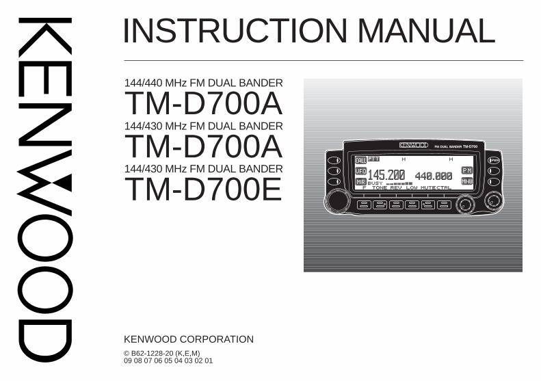
INSTRUCTION MANUAL144/440 MHz FM DUAL BANDER
144/430 MHz FM DUAL BANDER
TM-D700ATM-D700A
144/430 MHz FM DUAL BANDER
TM-D700E
THANK YOU!We are grateful you decided to purchase thisKENWOOD FM transceiver. KENWOOD alwaysprovides Amateur Radio products which surprise andexcite serious hobbyists. This transceiver is noexception. This time KENWOOD presents a mobile witha built-in TNC to make data communications much moreconvenient than before. KENWOOD believes that thisproduct will satisfy your requirements on both voice anddata communications.
MODELS COVERED BY THIS MANUALThe models listed below are covered by this manual.
TM-D700A: 144/440 MHz FM Dual Bander(U.S.A./ Canada)
TM-D700E: 144/430 MHz FM Dual Bander(Europe)
TM-D700A: 144/430 MHz FM Dual Bander(General market)
FEATURESThis transceiver has the following main features:
• Has a built-in TNC which conforms to the AX.25protocol. With a portable computer, allows you toenjoy Packet operation quite easily.
• Includes a program for dealing with data formatssupported by Automatic Packet/ Position ReportingSystem (APRS).
• Is capable of receiving packet data on one band whilereceiving audio on the other band.
• Enhanced Programmable Memory (PM) channelsstore virtually entire current operating environmentsfor your quick recall.
• Contains a total of 200 memory channels to programfrequencies and other various data. Allows eachmemory channel to be named using up to 8alphanumeric and special ASCII characters.
• “Visual Scan” graphically and simultaneously showsthe conditions of up to 181 frequency channels.
• Continuous Tone Coded Squelch System (CTCSS) orDigital Code Squelch (DCS) rejects unwanted callsfrom other stations.
• The separate front panel can be mounted in aconvenient different place from the main unit.
• Equipped with an easy-to-read large LCD withalphanumeric display capability.
• Enhances the functions of an optional VC-H1Interactive Visual Communicator designed forplug-and-play color slow-scan television (SSTV).
• Utilizes Sky Command System 2 designed to controla KENWOOD HF transceiver at a remote location(U.S.A./ Canada only).
i
PRECAUTIONS
Please observe the following precautions to preventfire, personal injury, and transceiver damage:
• When operating mobile, do not attempt to configureyour transceiver while driving because it is simplytoo dangerous.
• Be aware of local laws pertaining to the use ofheadphones/headsets while driving on publicroads. If in doubt, do not wear headphones whilemobiling.
• Do not transmit with high output power forextended periods. The transceiver may overheat.
• Do not modify this transceiver unless instructed bythis manual or by KENWOOD documentation.
• Do not expose the transceiver to long periods ofdirect sunlight nor place the transceiver close toheating appliances.
• Do not place the transceiver in excessively dustyareas, humid areas, wet areas, nor on unstablesurfaces.
• If an abnormal odor or smoke is detected comingfrom the transceiver, turn OFF the powerimmediately. Contact a KENWOOD service stationor your dealer.
• The transceiver is designed for a 13.8 V powersource. Never use a 24 V battery to power thetransceiver.
NOTICES TO THE USEROne or more of the following statements may beapplicable:
FCC WARNING
This equipment generates or uses radio frequency energy. Changes ormodifications to this equipment may cause harmful interference unlessthe modifications are expressly approved in the instruction manual. Theuser could lose the authority to operate this equipment if an unauthorizedchange or modification is made.
INFORMATION TO THE DIGITAL DEVICE USER REQUIRED BYTHE FCC
This equipment has been tested and found to comply with the limits for aClass B digital device, pursuant to Part 15 of the FCC Rules. Theselimits are designed to provide reasonable protection against harmfulinterference in a residential installation.
This equipment generates, uses and can generate radio frequencyenergy and, if not installed and used in accordance with the instructions,may cause harmful interference to radio communications. However,there is no guarantee that the interference will not occur in a particularinstallation. If this equipment does cause harmful interference to radio ortelevision reception, which can be determined by turning the equipmentoff and on, the user is encouraged to try to correct the interference byone or more of the following measures:• Reorient or relocate the receiving antenna.• Increase the separation between the equipment and receiver.• Connect the equipment to an outlet on a circuit different from that to
which the receiver is connected.• Consult the dealer for technical assistance.
When condensation occurs inside the transceiver:
Condensation may occur inside the transceiver in such a case where theroom is warmed using a heater on cold days or where the transceiver isquickly moved from a cold room to a warm room. When condensationoccurs, the microcomputer and/or the transmit/receive circuits maybecome unstable, resulting in transceiver malfunction. If this happens,turn OFF the transceiver and just wait for a while. When the condenseddroplets disappear, the transceiver will function normally.
ii
CONTENTSCHAPTER 4 OPERATING BASICS
SWITCHING POWER ON/OFF ............................... 19ADJUSTING VOLUME ............................................ 19SELECTING A BAND .............................................. 19SELECTING A FREQUENCY .................................. 20ADJUSTING SQUELCH .......................................... 20TRANSMITTING ...................................................... 21
Selecting Output Power ...................................... 21CHAPTER 5 MENU SET-UP
MENU ACCESS ...................................................... 22MENU CONFIGURATION ....................................... 23
CHAPTER 6 OPERATING THROUGH REPEATERSPROGRAMMING OFFSET ...................................... 29
Selecting Offset Direction .................................... 29Selecting Offset Frequency ................................. 29Activating Tone Function ..................................... 30Selecting a Tone Frequency ................................ 30
AUTOMATIC REPEATER OFFSET ......................... 31TRANSMITTING A 1750 Hz TONE .......................... 32REVERSE FUNCTION ............................................ 33AUTOMATIC SIMPLEX CHECK (ASC) .................... 33TONE FREQ. ID ...................................................... 34
CHAPTER 7 MEMORY CHANNELSSIMPLEX & REPEATER OR ODD-SPLITMEMORY CHANNEL?............................................. 35STORING SIMPLEX FREQUENCIES ORSTANDARD REPEATER FREQUENCIES ............... 36
SUPPLIED ACCESSORIES ...................................... 1CONVENTIONS FOLLOWED IN THIS MANUAL....... 1
CHAPTER 1 PREPARATIONMOBILE INSTALLATION ........................................... 2
Main Unit Installation ............................................. 2Front Panel Installation ......................................... 3
FIXED STATION INSTALLATION ............................... 4MODULAR PLUG CABLE CONNECTION ................. 4DC POWER CABLE CONNECTION .......................... 5
Mobile Operation .................................................. 5Fixed Station Operation ........................................ 6Replacing Fuses ................................................... 7
ANTENNA CONNECTION ......................................... 7ACCESSORY CONNECTIONS ................................. 8
External Speakers ................................................ 8Microphone........................................................... 8
CHAPTER 2 YOUR FIRST QSOCHAPTER 3 GETTING ACQUAINTED
FRONT PANEL ........................................................ 10MAIN UNIT- FRONT ................................................ 12MAIN UNIT-REAR ................................................... 12MICROPHONE ........................................................ 13INDICATORS ........................................................... 14BASIC TRANSCEIVER MODES.............................. 15BUTTON FUNCTION DISPLAY ............................... 16BAND A & B ............................................................. 17TX BAND AND CONTROL BAND ............................ 17MIC KEYPAD DIRECT ENTRY (MC-53DM ONLY) .. 18
iii
1
2
3
4
5
6
7
8
9
10
11
12
13
14
15
16
17
18
19
20
21
22
PROGRAM SCAN ................................................... 52Setting Scan Limits ............................................. 52Using Program Scan ........................................... 53
MHz SCAN .............................................................. 53CALL/VFO SCAN .................................................... 54CALL/MEMORY SCAN ............................................ 54
CHAPTER 10 CONTINUOUS TONE CODED SQUELCHSYSTEM (CTCSS)
USING CTCSS ........................................................ 55CTCSS FREQ. ID .................................................... 56
CHAPTER 11 DIGITAL CODE SQUELCH (DCS)USING DCS ............................................................ 57DCS CODE ID ......................................................... 58
CHAPTER 12 DUAL TONE MULTI-FREQUENCY (DTMF)FUNCTIONS (WITH MC-53DM ONLY)
MANUAL DIALING .................................................. 59DTMF Monitor ..................................................... 59
AUTOMATIC DIALER .............................................. 60Storing a DTMF Number in Memory.................... 60Transmitting a Stored DTMF Number .................. 61Selecting TX Speed ............................................ 61Selecting Pause Duration .................................... 61
CHAPTER 13 PROGRAMMABLE FUNCTION (PF) KEYSCHAPTER 14 AUXILIARY FUNCTIONS
DIRECT FREQUENCY ENTRY(WITH MC-53DM ONLY) ......................................... 63CHANGING FREQUENCY STEP SIZE ................... 64PROGRAMMABLE VFO.......................................... 64
STORING ODD-SPLIT REPEATERFREQUENCIES....................................................... 36RECALLING A MEMORY CHANNEL ....................... 37CLEARING A MEMORY CHANNEL ......................... 37NAMING A MEMORY CHANNEL ............................. 38CALL CHANNEL ...................................................... 39
Recalling the Call Channel .................................. 39Reprogramming the Call Channel ....................... 39
MEMORY-TO-VFO TRANSFER .............................. 40CHANNEL DISPLAY ................................................ 40PARTIAL OR FULL RESET?.................................... 41
CHAPTER 8 PROGRAMMABLE MEMORY (PM)PROGRAMMABLE INFORMATION......................... 42APPLICATION EXAMPLES ..................................... 43STORING IN PM CHANNELS ................................. 44RECALLING A PM CHANNEL ................................. 44AUTO PM CHANNEL STORE ................................. 45PM CHANNEL RESET ............................................ 45
CHAPTER 9 SCANVISUAL SCAN ......................................................... 47
Selecting the Number of Channels ...................... 47Using Visual Scan ............................................... 48
SELECTING SCAN RESUME METHOD ................. 49VFO SCAN ............................................................. 50MEMORY SCAN...................................................... 50
Locking Out a Memory Channel .......................... 51GROUP SCAN ........................................................ 51
iv
CHAPTER 16 WIRELESS REMOTE CONTROL(U.S.A./ CANADA ONLY)
PREPARATION ....................................................... 74CONTROL OPERATION.......................................... 75
CHAPTER 17 SKY COMMAND 22222 (U.S.A./ CANADA ONLY)
CONNECTING THE TRANSPORTER WITHTHE HF TRANSCEIVER ......................................... 77PREPARATION FLOW ............................................ 78PROGRAMMING CALL SIGNS ............................... 79PROGRAMMING A TONE FREQUENCY ................ 79CONTROL OPERATION.......................................... 80
CHAPTER 18 REPEATER FUNCTION(U.S.A./ CANADA ONLY)
CHAPTER 19 VS-3 VOICE SYNTHESIZER (OPTIONAL)CHAPTER 20 OPTIONAL ACCESSORIESCHAPTER 21 INSTALLING OPTIONS
INSTALLING THE VS-3 VOICESYNTHESIZER UNIT .............................................. 85INSTALLING THE PG-4X EXTENSIONCABLE KIT .............................................................. 85
CHAPTER 22 MAINTENANCEGENERAL INFORMATION ...................................... 87SERVICE................................................................. 87SERVICE NOTE ...................................................... 87CLEANING .............................................................. 87TROUBLESHOOTING ............................................. 88
SPECIFICATIONSINDEX
DISPLAY DIMMER .................................................. 65AUTO DIMMER CHANGE ....................................... 65DISPLAY CONTRAST ADJUST ............................... 65POSITIVE/ NEGATIVE REVERSAL ......................... 65BLANKING A BAND DISPLAY ................................. 66AUTOMATIC BAND CHANGE (A.B.C.) .................... 66TRANSCEIVER LOCK ............................................ 67ALL-CONTROL LOCK ............................................. 67CHANGING MULTI-FUNCTIONBUTTON LABELS ................................................... 67S-METER SQUELCH .............................................. 68
Squelch Hang Time ............................................ 68CHANGING BEEP VOLUME ................................... 69KEY BEEP ON/ OFF................................................ 69SWITCHING FM/AM MODE .................................... 69ADVANCED INTERCEPT POINT (AIP) ................... 69TIME-OUT TIMER (TOT) ......................................... 70AUTOMATIC POWER OFF (APO) ........................... 70POWER-ON MESSAGE .......................................... 71DISPLAY DEMONSTRATION .................................. 71CHANGING SPEAKER CONFIGURATIONS ........... 72SPEAKER MUTE .................................................... 72CHANGING TX/RX DEVIATION (TM-D700E ONLY).................................................. 72
CHAPTER 15 MICROPHONE CONTROL (WITH MC-53DM ONLY)
1
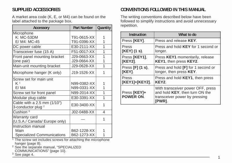
SUPPLIED ACCESSORIESA market area code (K, E, or M4) can be found on thelabel attached to the package box.
1 The screw set includes screws for attaching the microphonehanger page 8.
2 See the separate manual, “SPECIALIZEDCOMMUNICATIONS” page 10.
3 See page 4.
CONVENTIONS FOLLOWED IN THIS MANUALThe writing conventions described below have beenfollowed to simplify instructions and avoid unnecessaryrepetition.yrosseccA rebmuNtraP ytitnauQ
enohporciMMD35-CM:K
54-CM:4M/EXX-5160-19TXX-6930-19T
11
elbacrewopCD XX-1112-03E 1)A51(esufreviecsnarT XX-7100-15F 1
tekcarbgnitnuomlenaptnorF)riapeno(
XX-3660-92JXX-4660-92J
11
tekcarbgnitnuomtinu-niaM XX-8260-92J 1
)ylnoK(regnahenohporciM XX-6251-91J 1
tinuniamrofteswercSK 1
4M/EXX-2830-99NXX-1330-99N
11
lenaptnorfrofteswercS XX-4102-99N 1elbacgulpraludoM XX-1933-03E 1
)"01/1(mm5.2ahtiwelbaCgulprotcudnoc-3 2 XX-0043-03E 1
noihsuC 3 XX-8840-20J 4dracytnarraW
)ylnoeporuE/adanaC/.A.S.U( — 1
launamnoitcurtsnIniaM
snoitacinummoCdezilaicepSXX-8221-26BXX-3721-26B
11
noitcurtsnI odottahWsserP ]YEK[ . esaelerdnasserP YEK .
sserP)s1(]YEK[ .
dlohdnasserP YEK rodnoces1rof.regnol
sserP ]1YEK[ ,]2YEK[ .
sserP 1YEK esaeler,yliratnemom1YEK sserpneht, 2YEK .
sserP )s1(]F[ ,]YEK[ .
dlohdnasserP ]F[ rodnoces1rofsserpneht,regnol YEK .
sserP]2YEK[+]1YEK[ .
dlohdnasserP 1YEK sserpneht,2YEK .
sserP +]YEK[NOREWOP .
sserp,FFOrewopreviecsnarthtiWdlohdna YEK ehtNOnrutneht,
gnisserpybrewopreviecsnart]RWP[ .
2
1
PREPARATION
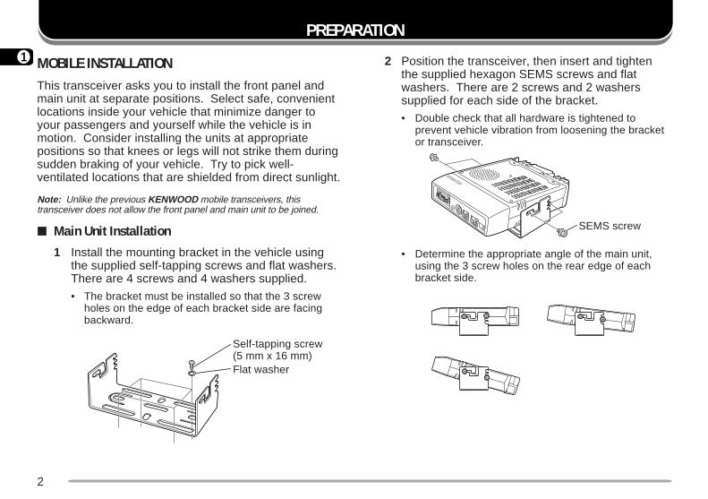
2 Position the transceiver, then insert and tightenthe supplied hexagon SEMS screws and flatwashers. There are 2 screws and 2 washerssupplied for each side of the bracket.
• Double check that all hardware is tightened toprevent vehicle vibration from loosening the bracketor transceiver.
• Determine the appropriate angle of the main unit,using the 3 screw holes on the rear edge of eachbracket side.
MOBILE INSTALLATIONThis transceiver asks you to install the front panel andmain unit at separate positions. Select safe, convenientlocations inside your vehicle that minimize danger toyour passengers and yourself while the vehicle is inmotion. Consider installing the units at appropriatepositions so that knees or legs will not strike them duringsudden braking of your vehicle. Try to pick well-ventilated locations that are shielded from direct sunlight.
Note: Unlike the previous KENWOOD mobile transceivers, thistransceiver does not allow the front panel and main unit to be joined.
Main Unit Installation
1 Install the mounting bracket in the vehicle usingthe supplied self-tapping screws and flat washers.There are 4 screws and 4 washers supplied.
• The bracket must be installed so that the 3 screwholes on the edge of each bracket side are facingbackward.
SEMS screw
Self-tapping screw(5 mm x 16 mm)Flat washer
3
1
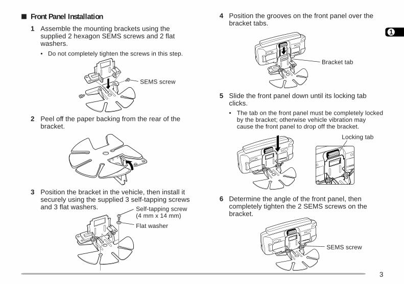
Front Panel Installation
1 Assemble the mounting brackets using thesupplied 2 hexagon SEMS screws and 2 flatwashers.
• Do not completely tighten the screws in this step.
2 Peel off the paper backing from the rear of thebracket.
3 Position the bracket in the vehicle, then install itsecurely using the supplied 3 self-tapping screwsand 3 flat washers.
4 Position the grooves on the front panel over thebracket tabs.
5 Slide the front panel down until its locking tabclicks.• The tab on the front panel must be completely locked
by the bracket; otherwise vehicle vibration maycause the front panel to drop off the bracket.
6 Determine the angle of the front panel, thencompletely tighten the 2 SEMS screws on thebracket.
SEMS screw
Self-tapping screw(4 mm x 14 mm)
Flat washer
Bracket tab
Locking tab
SEMS screw
4
1
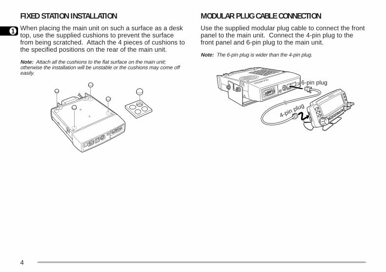
FIXED STATION INSTALLATIONWhen placing the main unit on such a surface as a desktop, use the supplied cushions to prevent the surfacefrom being scratched. Attach the 4 pieces of cushions tothe specified positions on the rear of the main unit.
Note: Attach all the cushions to the flat surface on the main unit;otherwise the installation will be unstable or the cushions may come offeasily.
MODULAR PLUG CABLE CONNECTIONUse the supplied modular plug cable to connect the frontpanel to the main unit. Connect the 4-pin plug to thefront panel and 6-pin plug to the main unit.
Note: The 6-pin plug is wider than the 4-pin plug.
4-pin plug
6-pin plug
5
1
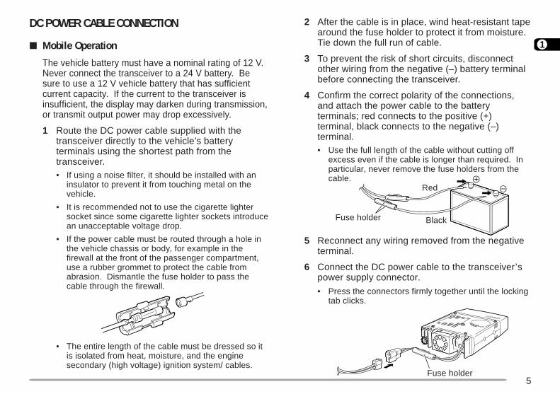
2 After the cable is in place, wind heat-resistant tapearound the fuse holder to protect it from moisture.Tie down the full run of cable.
3 To prevent the risk of short circuits, disconnectother wiring from the negative (–) battery terminalbefore connecting the transceiver.
4 Confirm the correct polarity of the connections,and attach the power cable to the batteryterminals; red connects to the positive (+)terminal, black connects to the negative (–)terminal.• Use the full length of the cable without cutting off
excess even if the cable is longer than required. Inparticular, never remove the fuse holders from thecable.
5 Reconnect any wiring removed from the negativeterminal.
6 Connect the DC power cable to the transceiver’spower supply connector.
• Press the connectors firmly together until the lockingtab clicks.
DC POWER CABLE CONNECTION
Mobile Operation
The vehicle battery must have a nominal rating of 12 V.Never connect the transceiver to a 24 V battery. Besure to use a 12 V vehicle battery that has sufficientcurrent capacity. If the current to the transceiver isinsufficient, the display may darken during transmission,or transmit output power may drop excessively.
1 Route the DC power cable supplied with thetransceiver directly to the vehicle’s batteryterminals using the shortest path from thetransceiver.• If using a noise filter, it should be installed with an
insulator to prevent it from touching metal on thevehicle.
• It is recommended not to use the cigarette lightersocket since some cigarette lighter sockets introducean unacceptable voltage drop.
• If the power cable must be routed through a hole inthe vehicle chassis or body, for example in thefirewall at the front of the passenger compartment,use a rubber grommet to protect the cable fromabrasion. Dismantle the fuse holder to pass thecable through the firewall.
• The entire length of the cable must be dressed so itis isolated from heat, moisture, and the enginesecondary (high voltage) ignition system/ cables.
Red
BlackFuse holder
Fuse holder

6
1
2 Connect the transceiver’s DC power connector tothe connector on the DC power cable.
• Press the connectors firmly together until the lockingtab clicks.
Note: For your transceiver to fully exhibit its performance capabilities,
the following optional power supply is recommended:PS-33 (20.5 A, 25% duty cycle).
Before connecting the DC power supply to the transceiver, besure to switch the transceiver and the DC power supply OFF.
Do not plug the DC power supply into an AC outlet until youmake all connections.
Fixed Station Operation
In order to use this transceiver for fixed stationoperation, you will need a separate 13.8 V DC powersupply that must be purchased separately. Therecommended current capacity of your power supplyis 12 A.
1 Connect the DC power cable to the regulated DCpower supply and check that polarities are correct(Red: positive, Black: negative).• DO NOT directly connect the transceiver to an AC
outlet.
• Use the supplied DC power cable to connect thetransceiver to a regulated power supply.
• Do not substitute a cable with smaller gauge wires.
Fuse holder
Black (–)Red (+)
To AC outlet
Regulated DC powersupply
Fuse holder
7
1
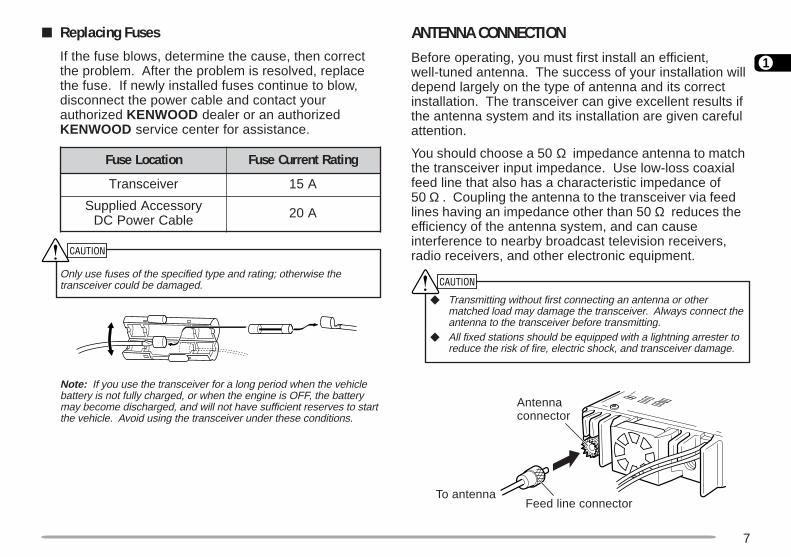
Replacing Fuses
If the fuse blows, determine the cause, then correctthe problem. After the problem is resolved, replacethe fuse. If newly installed fuses continue to blow,disconnect the power cable and contact yourauthorized KENWOOD dealer or an authorizedKENWOOD service center for assistance.
Only use fuses of the specified type and rating; otherwise thetransceiver could be damaged.
Note: If you use the transceiver for a long period when the vehiclebattery is not fully charged, or when the engine is OFF, the batterymay become discharged, and will not have sufficient reserves to startthe vehicle. Avoid using the transceiver under these conditions.
ANTENNA CONNECTIONBefore operating, you must first install an efficient,well-tuned antenna. The success of your installation willdepend largely on the type of antenna and its correctinstallation. The transceiver can give excellent results ifthe antenna system and its installation are given carefulattention.
You should choose a 50 Ω impedance antenna to matchthe transceiver input impedance. Use low-loss coaxialfeed line that also has a characteristic impedance of50 Ω . Coupling the antenna to the transceiver via feedlines having an impedance other than 50 Ω reduces theefficiency of the antenna system, and can causeinterference to nearby broadcast television receivers,radio receivers, and other electronic equipment.
Transmitting without first connecting an antenna or othermatched load may damage the transceiver. Always connect theantenna to the transceiver before transmitting.
All fixed stations should be equipped with a lightning arrester toreduce the risk of fire, electric shock, and transceiver damage.
noitacoLesuF gnitaRtnerruCesuF
reviecsnarT A51
yrosseccAdeilppuSelbaCrewoPCD A02
Feed line connector
Antennaconnector
To antenna

8
1
ACCESSORY CONNECTIONS
External Speakers
If you plan to use external speakers, choosespeakers with an impedance of 8 Ω . The externalspeaker jacks accept a 3.5 mm (1/8") mono (2-conductor) plug. Recommended speakers includethe SP-50B.
Microphone
To communicate in the voice modes, connect a 600 Ωmicrophone equipped with an 8-pin modular plug intothe modular socket on the front of the main unit.Press firmly on the plug until the locking tab clicks.
For the U.S.A./ Canada version, a microphone hanger issupplied. Attach the hanger to an appropriate positionusing the screws included in the screw set.
UPDC 8 V, 200 mA max.GNDSTBY (PTT)GND (MIC)MICNC: No connectionDWN
Microphonehanger
Microphonehanger screw(3 mm x 10 mm)

9
2
YOUR FIRST QSO
If you tend to discard instruction manuals along with thepackaging material .....please don’t. The 7 steps given here willget you on the air in your first QSO right away. So, you can enjoythe exhilaration that comes with opening a brand newtransceiver.
After trying the rig for a while, settle back in your mostcomfortable operating chair with this manual and your favoritedrink for an hour or two. The time spent will be worthwhile.
YOUR FIRST QSO
Switch ON the DC power supply, then press the PWR switch.
Turn the VOL and SQL controls to approximately 9 o’clock.
Press [BAND SEL] to select the VHF or UHF band.
Turn the Tuning control to select a frequency.
Press and hold Mic [PTT], then speak in a normal tone of voice.
Release Mic [PTT] to receive.
Repeat steps and to continue communication.
q
r wwe wwet
y
MC-53DM
10
3
GETTING ACQUAINTED
FRONT PANEL
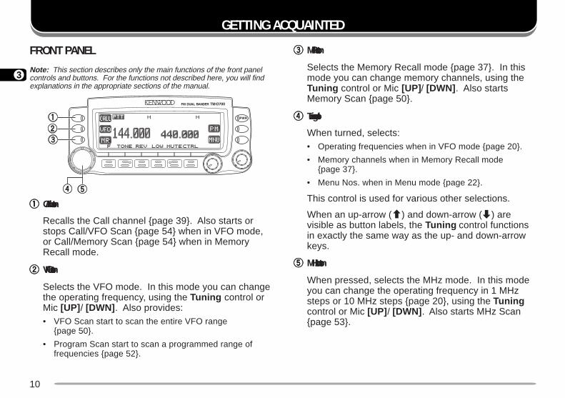
Note: This section describes only the main functions of the front panelcontrols and buttons. For the functions not described here, you will findexplanations in the appropriate sections of the manual.
qqqqq CALL button
Recalls the Call channel page 39. Also starts orstops Call/VFO Scan page 54 when in VFO mode,or Call/Memory Scan page 54 when in MemoryRecall mode.
wwwww VFO button
Selects the VFO mode. In this mode you can changethe operating frequency, using the Tuning control orMic [UP] / [DWN] . Also provides:• VFO Scan start to scan the entire VFO range
page 50.
• Program Scan start to scan a programmed range offrequencies page 52.
eeeee MR button
Selects the Memory Recall mode page 37. In thismode you can change memory channels, using theTuning control or Mic [UP] / [DWN] . Also startsMemory Scan page 50.
rrrrr Tuning control
When turned, selects:• Operating frequencies when in VFO mode page 20.
• Memory channels when in Memory Recall modepage 37.
• Menu Nos. when in Menu mode page 22.
This control is used for various other selections.
When an up-arrow (c) and down-arrow (d) arevisible as button labels, the Tuning control functionsin exactly the same way as the up- and down-arrowkeys.
ttttt MHz button
When pressed, selects the MHz mode. In this modeyou can change the operating frequency in 1 MHzsteps or 10 MHz steps page 20, using the Tuningcontrol or Mic [UP] / [DWN] . Also starts MHz Scanpage 53.
11
3
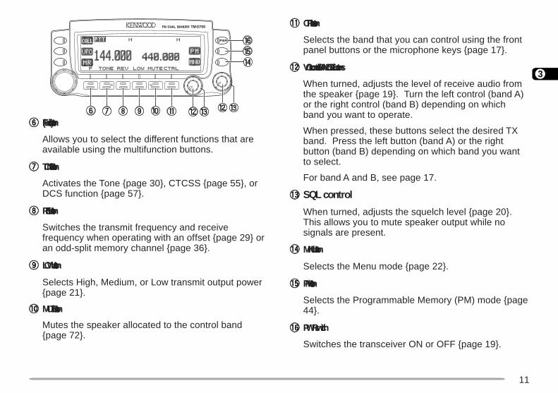
yyyyy F (Function) button
Allows you to select the different functions that areavailable using the multifunction buttons.
uuuuu TONE button
Activates the Tone page 30, CTCSS page 55, orDCS function page 57.
iiiii REV button
Switches the transmit frequency and receivefrequency when operating with an offset page 29 oran odd-split memory channel page 36.
ooooo LOW button
Selects High, Medium, or Low transmit output powerpage 21.
!0!0!0!0!0 MUTE button
Mutes the speaker allocated to the control bandpage 72.
!1!1!1!1!1 CTRL button
Selects the band that you can control using the frontpanel buttons or the microphone keys page 17.
!2!2!2!2!2 VOL controls/ BAND SEL buttons
When turned, adjusts the level of receive audio fromthe speaker page 19. Turn the left control (band A)or the right control (band B) depending on whichband you want to operate.
When pressed, these buttons select the desired TXband. Press the left button (band A) or the rightbutton (band B) depending on which band you wantto select.
For band A and B, see page 17.
!3!3!3!3!3 SQL control
When turned, adjusts the squelch level page 20.This allows you to mute speaker output while nosignals are present.
!4!4!4!4!4 MNU button
Selects the Menu mode page 22.
!5!5!5!5!5 PM button
Selects the Programmable Memory (PM) mode page44.
!6!6!6!6!6 PWR switch
Switches the transceiver ON or OFF page 19.

12
3
MAIN UNIT- FRONT
qqqqq COM connector
Accepts a DB-9 female connector for connecting to acomputer. See the separate manual, “SPECIALIZEDCOMMUNICATIONS” page 2.
wwwww GPS jack
Accepts a 2.5 mm (1/10") 3-conductor plug forconnecting to a GPS receiver. See the separate manual,“SPECIALIZED COMMUNICATIONS” page 10.
eeeee DATA connector
Accepts a 6-pin mini DIN plug for connecting to anexternal TNC or an optional VC-H1. See the separatemanual, “SPECIALIZED COMMUNICATIONS” pages 2and 35.
rrrrr PANEL connector
Insert one end of the supplied modular plug cable forconnecting the front panel page 4.
ttttt MIC connector
Insert the modular plug on the microphone cable untilthe locking tab clicks page 8.
yyyyy RESET buttonPress for 1 second or longer to perform Full Resetpage 41. No confirmation message appears. Usethis switch when the microcomputer and/or thememory chip malfunction because of ambient factors.
Note: With the transceiver power ON, do not connect cables to orremove from the front panel of the main unit.
MAIN UNIT- REAR
qqqqq Antenna connectorConnect an external antenna page 7. When makingtest transmissions, connect a dummy load in place ofthe antenna. The antenna system or load shouldhave an impedance of 50 Ω . The TM-D700E acceptsa male N-type connector and other versions accept amale PL-259 connector. This transceiver has onlyone antenna connector because of a built-in duplexer.
wwwww Power Input 13.8 V DC cable
Connect a 13.8 V DC power source. Use thesupplied DC power cable pages 5 and 6.
eeeee Speaker jacksIf you wish, connect an optional external speaker forclearer audio. These jacks accept a 3.5 mm (1/8")mono (2-conductor) plug. See page 8.
13
38
MIC
LOCK
ELECTRET CONDENSER MIC
MADE IN JAPAN
DWN UP
VFO MR PFCALL
3
5
4
2 1
6
7
4
12
37
6
5
6
8
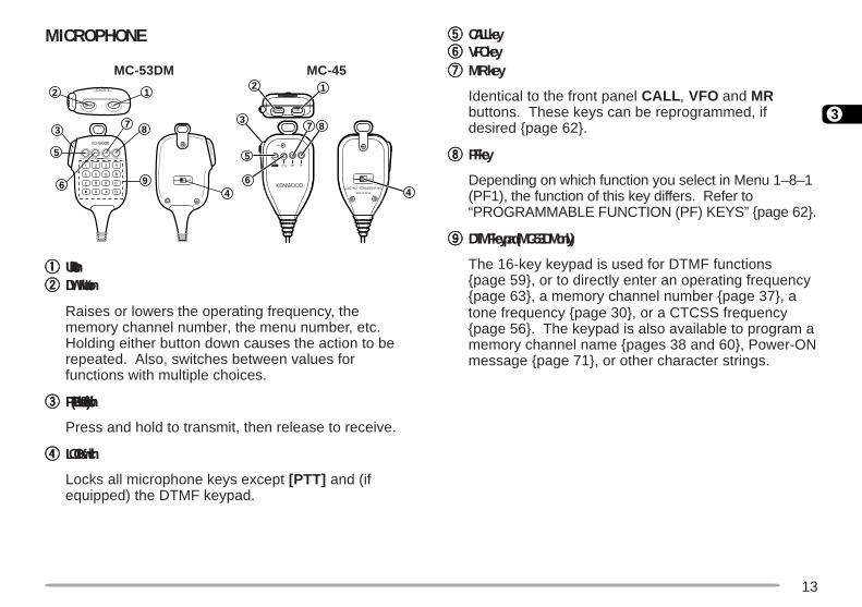
MICROPHONE
qqqqq UP buttonwwwww DWN button
Raises or lowers the operating frequency, thememory channel number, the menu number, etc.Holding either button down causes the action to berepeated. Also, switches between values forfunctions with multiple choices.
eeeee PTT (Push-to-Talk) switch
Press and hold to transmit, then release to receive.
rrrrr LOCK switch
Locks all microphone keys except [PTT] and (ifequipped) the DTMF keypad.
ttttt CALL keyyyyyy VFO keyuuuuu MR key
Identical to the front panel CALL , VFO and MRbuttons. These keys can be reprogrammed, ifdesired page 62.
iiiii PF key
Depending on which function you select in Menu 1–8–1(PF1), the function of this key differs. Refer to“PROGRAMMABLE FUNCTION (PF) KEYS” page 62.
ooooo DTMF keypad (MC-53DM only)
The 16-key keypad is used for DTMF functionspage 59, or to directly enter an operating frequencypage 63, a memory channel number page 37, atone frequency page 30, or a CTCSS frequencypage 56. The keypad is also available to program amemory channel name pages 38 and 60, Power-ONmessage page 71, or other character strings.
MC-53DM MC-45
14
3
rotacidnI uoYtahWdetceleS
otsserPuoYtahWlecnaC
.feRegaP
tuo-dekcoLyromemlennahc
.3–4–1uneMesU 15
dnaBotuAegnahC ]F[ , ].C.B.A[ 66
reviecsnarTkcoL ]F[ , ]zHM[ 76
kcoLlortnoc-llA REWOP+]zHM[NO neht, ]F[ , ]zHM[ 76
etuMrekaepS ]ETUM[ 27
edomtekcaP )s1(]F[ , ]CNT[ )4(
edomSRPA )s1(]F[ , ]CNT[ ,)s1(]F[ , ]CNT[ )11(
timsnartworraNnoitaived 1 .6–3–1uneMesU 27
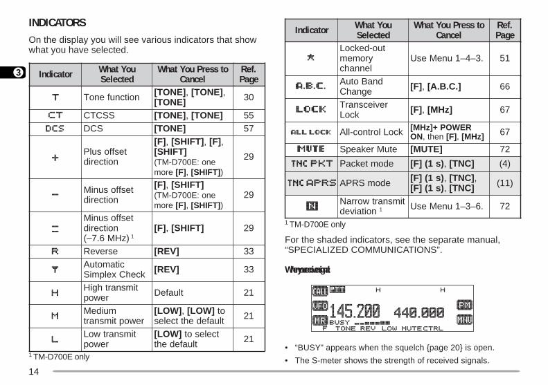
INDICATORSOn the display you will see various indicators that showwhat you have selected.
1 TM-D700E only
1 TM-D700E only
For the shaded indicators, see the separate manual,“SPECIALIZED COMMUNICATIONS”.
When you receive a signal:
• “BUSY” appears when the squelch page 20 is open.
• The S-meter shows the strength of received signals.
rotacidnI uoYtahWdetceleS
otsserPuoYtahWlecnaC
.feRegaP
noitcnufenoT ]ENOT[ , ]ENOT[ ,]ENOT[ 03
SSCTC ]ENOT[ , ]ENOT[ 55SCD ]ENOT[ 75
tesffosulPnoitcerid
]F[ , ]TFIHS[ , ]F[ ,]TFIHS[
eno:E007D-MT(erom ]F[ , ]TFIHS[ )
92
tesffosuniMnoitcerid
]F[ , ]TFIHS[eno:E007D-MT(
erom ]F[ , ]TFIHS[ )92
tesffosuniMnoitcerid
)zHM6.7–( 1]F[ , ]TFIHS[ 92
esreveR ]VER[ 33citamotuA
kcehCxelpmiS ]VER[ 33
timsnarthgiHrewop tluafeD 12
muideMrewoptimsnart
]WOL[ , ]WOL[ ottluafedehttceles 12
timsnartwoLrewop
]WOL[ tcelesottluafedeht 12
15
3
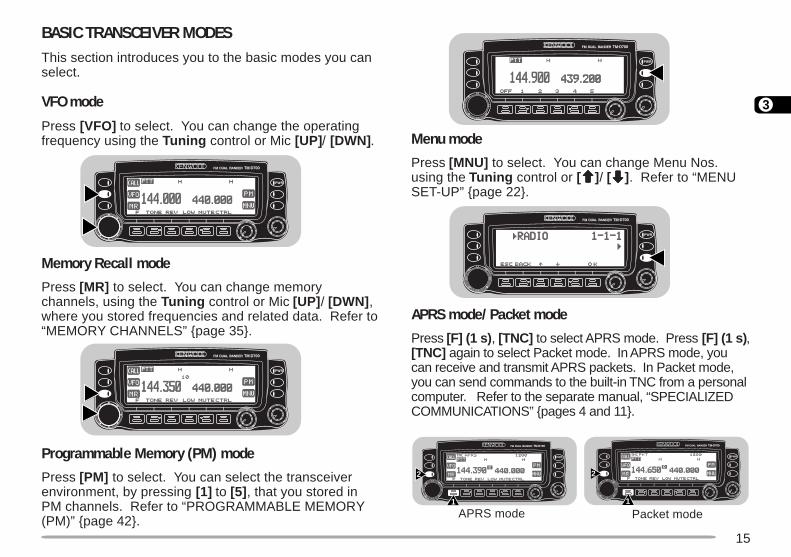
BASIC TRANSCEIVER MODESThis section introduces you to the basic modes you canselect.
VFO mode
Press [VFO] to select. You can change the operatingfrequency using the Tuning control or Mic [UP] / [DWN] .
Memory Recall mode
Press [MR] to select. You can change memorychannels, using the Tuning control or Mic [UP] / [DWN] ,where you stored frequencies and related data. Refer to“MEMORY CHANNELS” page 35.
Programmable Memory (PM) mode
Press [PM] to select. You can select the transceiverenvironment, by pressing [1] to [5] , that you stored inPM channels. Refer to “PROGRAMMABLE MEMORY(PM)” page 42.
Menu mode
Press [MNU] to select. You can change Menu Nos.using the Tuning control or [ccccc]/ [ddddd]. Refer to “MENUSET-UP” page 22.
APRS mode/ Packet mode
Press [F] (1 s) , [TNC] to select APRS mode. Press [F] (1 s) ,[TNC] again to select Packet mode. In APRS mode, youcan receive and transmit APRS packets. In Packet mode,you can send commands to the built-in TNC from a personalcomputer. Refer to the separate manual, “SPECIALIZEDCOMMUNICATIONS” pages 4 and 11.
1
2
1
2
APRS mode Packet mode
16
3
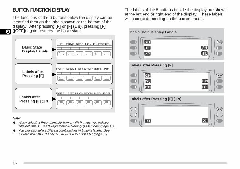
BUTTON FUNCTION DISPLAYThe functions of the 6 buttons below the display can beidentified through the labels shown at the bottom of thedisplay. After pressing [F] or [F] (1 s) , pressing [F]([OFF] ) again restores the basic state.
Note: When selecting Programmable Memory (PM) mode, you will see
different labels. See “Programmable Memory (PM) mode” page 15. You can also select different combinations of buttons labels. See
“CHANGING MULTI-FUNCTION BUTTON LABELS ” page 67.
The labels of the 5 buttons beside the display are shownat the left end or right end of the display. These labelswill change depending on the current mode.
Basic StateDisplay Labels
Labels afterPressing [F]
Labels afterPressing [F] (1 s)
Basic State Display Labels
Labels after Pressing [F]
Labels after Pressing [F] (1 s)
17
3
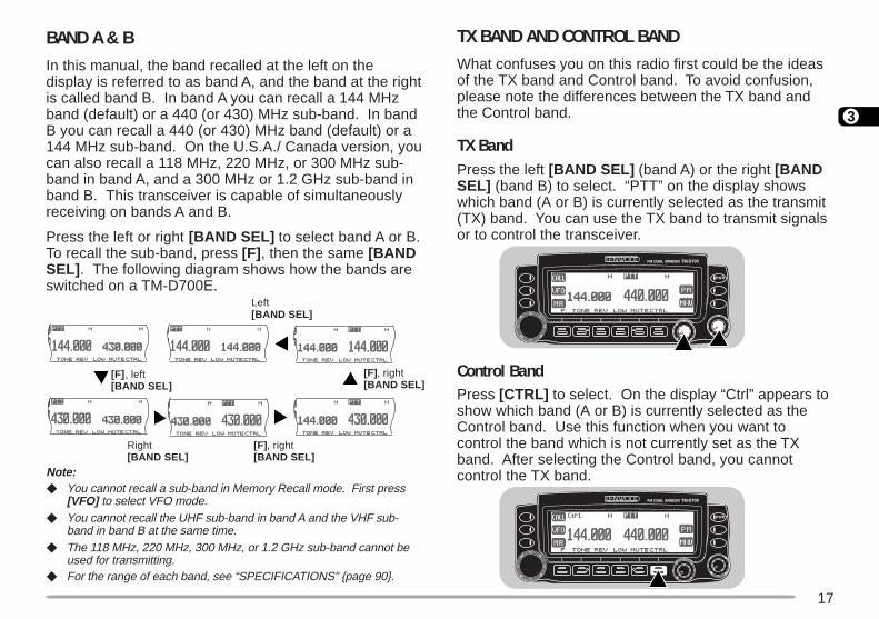
BAND A & BIn this manual, the band recalled at the left on thedisplay is referred to as band A, and the band at the rightis called band B. In band A you can recall a 144 MHzband (default) or a 440 (or 430) MHz sub-band. In bandB you can recall a 440 (or 430) MHz band (default) or a144 MHz sub-band. On the U.S.A./ Canada version, youcan also recall a 118 MHz, 220 MHz, or 300 MHz sub-band in band A, and a 300 MHz or 1.2 GHz sub-band inband B. This transceiver is capable of simultaneouslyreceiving on bands A and B.
Press the left or right [BAND SEL] to select band A or B.To recall the sub-band, press [F] , then the same [BANDSEL] . The following diagram shows how the bands areswitched on a TM-D700E.
Note: You cannot recall a sub-band in Memory Recall mode. First press
[VFO] to select VFO mode. You cannot recall the UHF sub-band in band A and the VHF sub-
band in band B at the same time. The 118 MHz, 220 MHz, 300 MHz, or 1.2 GHz sub-band cannot be
used for transmitting. For the range of each band, see “SPECIFICATIONS” page 90.
TX BAND AND CONTROL BANDWhat confuses you on this radio first could be the ideasof the TX band and Control band. To avoid confusion,please note the differences between the TX band andthe Control band.
TX BandPress the left [BAND SEL] (band A) or the right [BANDSEL] (band B) to select. “PTT” on the display showswhich band (A or B) is currently selected as the transmit(TX) band. You can use the TX band to transmit signalsor to control the transceiver.
Control BandPress [CTRL] to select. On the display “Ctrl” appears toshow which band (A or B) is currently selected as theControl band. Use this function when you want tocontrol the band which is not currently set as the TXband. After selecting the Control band, you cannotcontrol the TX band.
[F] , left[BAND SEL]
Right[BAND SEL]
[F] , right[BAND SEL]
Left[BAND SEL]
[F] , right[BAND SEL]
18
3
MIC KEYPAD DIRECT ENTRY (MC-53DM ONLY)The keypad on the MC-53DM allows you to makevarious entries depending on which mode thetransceiver is in.
In VFO or Memory Recall mode, use the Mic keypad toselect a frequency page 63 or memory channel numberpage 37. In Tone or CTCSS freq. Select mode, use thekeypad to select a Tone frequency page 30 or CTCSSfrequency page 56. First press the Mic PF keyprogrammed as the ENTER key page 62.
To manually send a DTMF number, press and hold Mic[PTT] , then press the DTMF keys on the Mic keypadpage 59 in sequence.
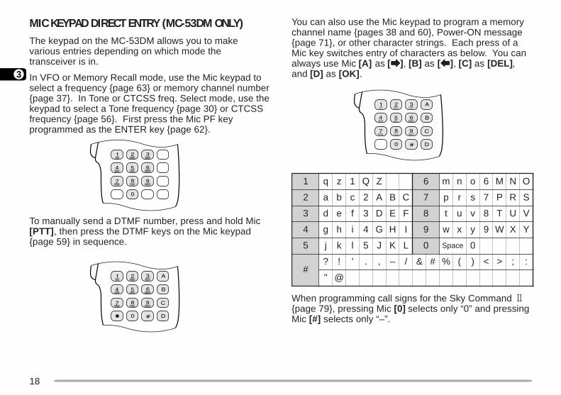
You can also use the Mic keypad to program a memorychannel name pages 38 and 60, Power-ON messagepage 71, or other character strings. Each press of aMic key switches entry of characters as below. You canalways use Mic [A] as [aaaaa], [B] as [bbbbb], [C] as [DEL] ,and [D] as [OK] .
When programming call signs for the Sky Command 2page 79, pressing Mic [0] selects only “0” and pressingMic [#] selects only “–”.
1 q z 1 Q Z 6 m n o 6 M N O
2 a b c 2 A B C 7 p r s 7 P R S
3 d e f 3 D E F 8 t u v 8 T U V
4 g h i 4 G H I 9 w x y 9 W X Y
5 j k l 5 J K L 0 ecapS 0
#? ! ' . , – / & # % ( ) < > ; :
" @
19
4
OPERATING BASICS
ADJUSTING VOLUMETurn the VOL control clockwise to increase the audiolevel and counterclockwise to decrease the audio level.
• If background noise is inaudible because of the Squelchfunction, press the Mic PF key assigned the Monitorfunction page 62, then adjust the VOL control. Press thePF key again to cancel the Monitor function.
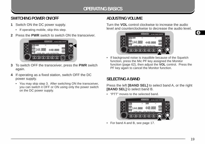
SELECTING A BANDPress the left [BAND SEL] to select band A, or the right[BAND SEL] to select band B.• “PTT” moves to the selected band.
• For band A and B, see page 17.
SWITCHING POWER ON/OFF1 Switch ON the DC power supply.
• If operating mobile, skip this step.
2 Press the PWR switch to switch ON the transceiver.
3 To switch OFF the transceiver, press the PWR switchagain.
4 If operating as a fixed station, switch OFF the DCpower supply.• You may skip step 3. After switching ON the transceiver,
you can switch it OFF or ON using only the power switchon the DC power supply.
20
4
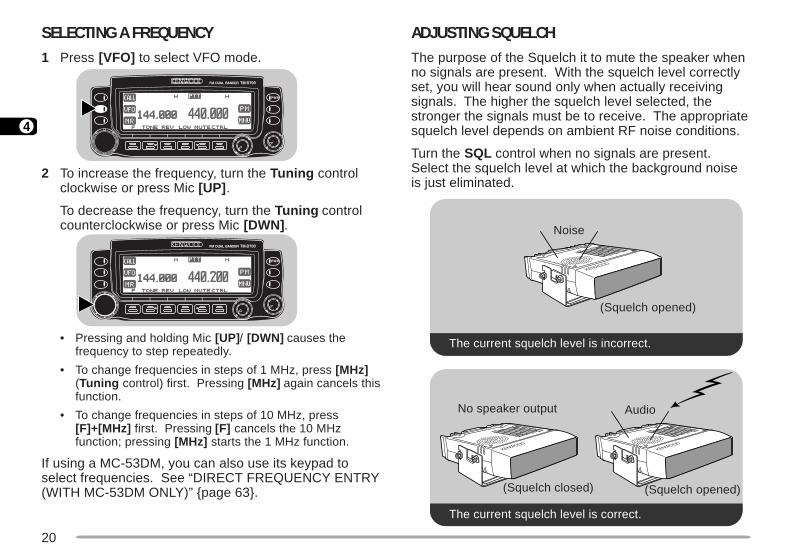
ADJUSTING SQUELCHThe purpose of the Squelch it to mute the speaker whenno signals are present. With the squelch level correctlyset, you will hear sound only when actually receivingsignals. The higher the squelch level selected, thestronger the signals must be to receive. The appropriatesquelch level depends on ambient RF noise conditions.
Turn the SQL control when no signals are present.Select the squelch level at which the background noiseis just eliminated.
The current squelch level is incorrect.
The current squelch level is correct.
SELECTING A FREQUENCY1 Press [VFO] to select VFO mode.
2 To increase the frequency, turn the Tuning controlclockwise or press Mic [UP] .
To decrease the frequency, turn the Tuning controlcounterclockwise or press Mic [DWN] .
• Pressing and holding Mic [UP] / [DWN] causes thefrequency to step repeatedly.
• To change frequencies in steps of 1 MHz, press [MHz](Tuning control) first. Pressing [MHz] again cancels thisfunction.
• To change frequencies in steps of 10 MHz, press[F]+[MHz] first. Pressing [F] cancels the 10 MHzfunction; pressing [MHz] starts the 1 MHz function.
If using a MC-53DM, you can also use its keypad toselect frequencies. See “DIRECT FREQUENCY ENTRY(WITH MC-53DM ONLY)” page 63.
Noise
(Squelch opened)
The current squelch level is incorrect.
No speaker output
(Squelch closed)
Audio
(Squelch opened)
The current squelch level is correct.

21
4
TRANSMITTING1 To transmit, press and hold Mic [PTT] and speak into
the microphone in a normal tone of voice.
• “ON AIR” and the RF power meter appear.
• Speaking too close to the microphone, or too loudly,may increase distortion and reduce intelligibility of yoursignals at the receiving station.
• The RF power meter shows the relative transmit outputpower.
2 When you finish speaking, release Mic [PTT] .
Time-Out Timer: Holding down Mic [PTT] for more than 10 minutescauses the transceiver to generate a beep and stop transmitting.Release, then press Mic [PTT] to resume transmitting. You may changethe time-out time to 3 or 5 minutes page 70.
Selecting Output Power
It’s wise to select lower transmit power if communicationis still reliable. This lowers the risk of interfering withothers on the band. When operating from batterypower, you will enjoy more operating time before acharge is necessary.
Press [LOW] to select high (“H”), medium (“M”), orlow (“L”) power. The default is high.• You can program a different power for band A and B.
Do not transmit at high output power for an extended period oftime. The transceiver could overheat and malfunction.
Continuous transmission causes the heat sink to overheat.Never touch the heat sink when it may be hot.
Note: When the transceiver overheats because of ambient hightemperature or continuous transmission, the protective circuit mayfunction to lower transmit output power.
22
5
MENU SET-UP
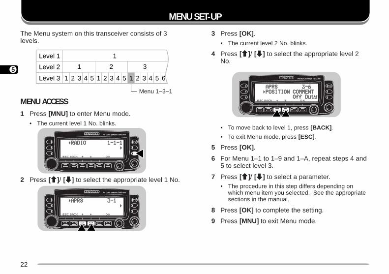
The Menu system on this transceiver consists of 3levels.
MENU ACCESS1 Press [MNU] to enter Menu mode.
• The current level 1 No. blinks.
2 Press [ccccc]/ [ddddd] to select the appropriate level 1 No.
3 Press [OK] .
• The current level 2 No. blinks.
4 Press [ccccc]/ [ddddd] to select the appropriate level 2No.
• To move back to level 1, press [BACK] .
• To exit Menu mode, press [ESC].
5 Press [OK] .
6 For Menu 1–1 to 1–9 and 1–A, repeat steps 4 and5 to select level 3.
7 Press [ccccc]/ [ddddd] to select a parameter.• The procedure in this step differs depending on
which menu item you selected. See the appropriatesections in the manual.
8 Press [OK] to complete the setting.
9 Press [MNU] to exit Menu mode.
Menu 1–3–1
Level 1 1
Level 2 1 2 3
1 2 3 4 51 2 3 41 2 3 4 5 5 6Level 3
23
5
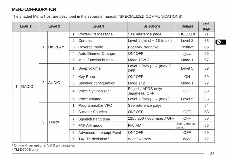
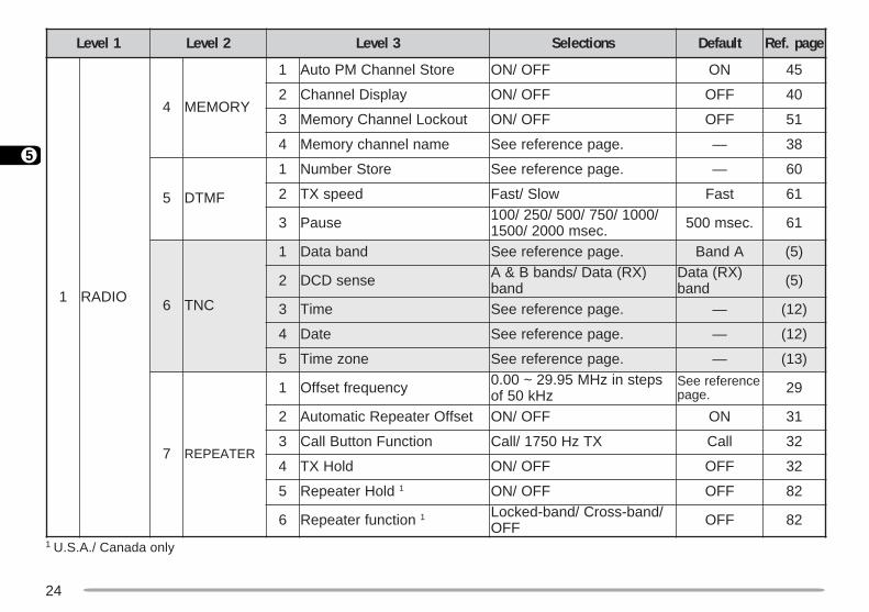
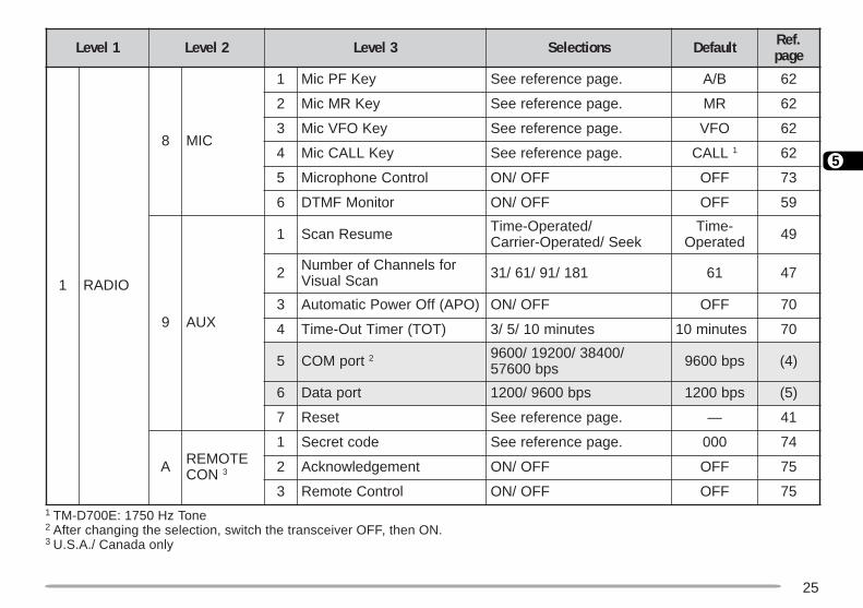
MENU CONFIGURATIONThe shaded Menu Nos. are described in the separate manual, “SPECIALIZED COMMUNICATIONS”.
1 Only with an optional VS-3 unit installed2 TM-D700E only
1leveL 2leveL 3leveL snoitceleS tluafeD .feRegap
1 OIDAR
1 YALPSID
1 egasseMNO-rewoP .egapecnerefereeS !!OLLEH 17
2 tsartnoC ).xam(61~).nim(1leveL 8leveL 56
3 edomesreveR evitageN/evitisoP evitisoP 56
4 egnahCremmiDotuA FFO/NO FFO 56
5 nottubnoitcnuf-itluM 3/2/1edoM 1edoM 76
2 OIDUA
1 emulovpeeB/).xam(7~).nim(1leveL
FFO5leveL 96
2 peeByeK FFO/NO NO 96
3 noitarugifnocrekaepS 2/1edoM 1edoM 27
4 rezisehtnySecioV 1 /ylnoSRPA/hsilgnEFFO/esenapaJ
FFO 38
5 emulovecioV 1 ).xam(7~).nim(1leveL 5leveL 38
3 XR/XT
1 OFVelbammargorP .egapecnerefereeS — 46
2 hcleuqSretem-S FFO/NO FFO 86
3 emitgnahhcleuqS FFO/.cesm005/052/521 FFO 86
4 edomMA/MF MA/MF ecnerefereeS.egap 96
5 tnioPtpecretnIdecnavdA FFO/NO FFO 96
6 noitaivedXR/XT 2 worraN/ediW ediW 27
24
5
1 U.S.A./ Canada only
1leveL 2leveL 3leveL snoitceleS tluafeD egap.feR
1 OIDAR
4 YROMEM
1 erotSlennahCMPotuA FFO/NO NO 54
2 yalpsiDlennahC FFO/NO FFO 04
3 tuokcoLlennahCyromeM FFO/NO FFO 15
4 emanlennahcyromeM .egapecnerefereeS — 83
5 FMTD
1 erotSrebmuN .egapecnerefereeS — 06
2 deepsXT wolS/tsaF tsaF 16
3 esuaP /0001/057/005/052/001.cesm0002/0051 .cesm005 16
6 CNT
1 dnabataD .egapecnerefereeS AdnaB )5(
2 esnesDCD )XR(ataD/sdnabB&Adnab
)XR(ataDdnab )5(
3 emiT .egapecnerefereeS — )21(
4 etaD .egapecnerefereeS — )21(
5 enozemiT .egapecnerefereeS — )31(
7 RETAEPER
1 ycneuqerftesffO spetsnizHM59.92~00.0zHk05fo
ecnerefereeS.egap 92
2 tesffOretaepeRcitamotuA FFO/NO NO 13
3 noitcnuFnottuBllaC XTzH0571/llaC llaC 23
4 dloHXT FFO/NO FFO 23
5 dloHretaepeR 1 FFO/NO FFO 28
6 noitcnufretaepeR 1 /dnab-ssorC/dnab-dekcoLFFO FFO 28
25
5
1 TM-D700E: 1750 Hz Tone2 After changing the selection, switch the transceiver OFF, then ON.3 U.S.A./ Canada only
1leveL 2leveL 3leveL snoitceleS tluafeD .feRegap
1 OIDAR
8 CIM
1 yeKFPciM .egapecnerefereeS B/A 26
2 yeKRMciM .egapecnerefereeS RM 26
3 yeKOFVciM .egapecnerefereeS OFV 26
4 yeKLLACciM .egapecnerefereeS LLAC 1 26
5 lortnoCenohporciM FFO/NO FFO 37
6 rotinoMFMTD FFO/NO FFO 95
9 XUA
1 emuseRnacS /detarepO-emiTkeeS/detarepO-reirraC
-emiTdetarepO 94
2 rofslennahCforebmuNnacSlausiV 181/19/16/13 16 74
3 )OPA(ffOrewoPcitamotuA FFO/NO FFO 07
4 )TOT(remiTtuO-emiT setunim01/5/3 setunim01 07
5 tropMOC 2 /00483/00291/0069spb00675 spb0069 )4(
6 tropataD spb0069/0021 spb0021 )5(
7 teseR .egapecnerefereeS — 14
A ETOMERNOC 3
1 edocterceS .egapecnerefereeS 000 47
2 tnemegdelwonkcA FFO/NO FFO 57
3 lortnoCetomeR FFO/NO FFO 57
26
5
1leveL 2leveL snoitceleS tluafeD .feRegap
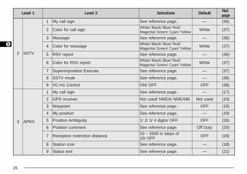
2 VTSS
1 ngisllacyM .egapecnerefereeS — )63(
2 ngisllacrofroloC /deR/eulB/kcalB/etihWwolleY/nayC/neerG/atnegaM etihW )73(
3 egasseM .egapecnerefereeS — )63(
4 egassemrofroloC /deR/eulB/kcalB/etihWwolleY/nayC/neerG/atnegaM etihW )73(
5 troperVSR .egapecnerefereeS — )63(
6 troperVSRrofroloC /deR/eulB/kcalB/etihWwolleY/nayC/neerG/atnegaM etihW )73(
7 etucexEnoitisopmirepuS .egapecnerefereeS — )73(
8 edomVTSS .egapecnerefereeS — )83(
9 lortnoC1H-CV FFO/NO FFO )83(
3 SRPA
1 ngisllacyM .egapecnerefereeS — )71(
2 reviecerSPG 69AEMN/AEMN/desutoN desutoN )01(
3 tniopyaW .egapecnerefereeS FFO )51(
4 noitisopyM .egapecnerefereeS — )91(
5 ytiugibmAnoitisoP FFO/stigid4/3/2/1 FFO )62(
6 tnemmocnoitisoP .egapecnerefereeS ytuDffO )02(
7 ecnatsidnoitcirtsernoitpeceR fospetsni0052~01FFO/01 FFO )62(
8 nocinoitatS .egapecnerefereeS — )81(
9 txetsutatS .egapecnerefereeS — )12(
27
5
1 U.S.A./ Canada: Mile and °F
1leveL 2leveL snoitceleS tluafeD .feRegap
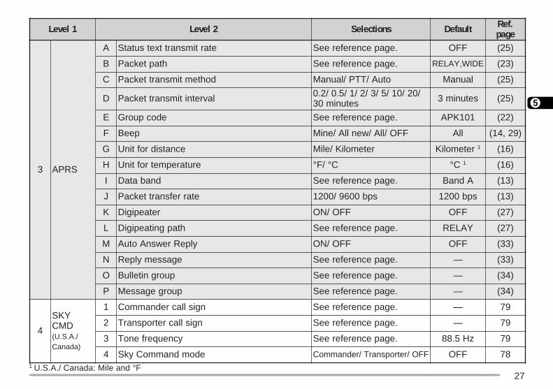
3 SRPA
A etartimsnarttxetsutatS .egapecnerefereeS FFO )52(
B htaptekcaP .egapecnerefereeS EDIW,YALER )32(
C dohtemtimsnarttekcaP otuA/TTP/launaM launaM )52(
D lavretnitimsnarttekcaP /02/01/5/3/2/1/5.0/2.0setunim03 setunim3 )52(
E edocpuorG .egapecnerefereeS 101KPA )22(
F peeB FFO/llA/wenllA/eniM llA )92,41(
G ecnatsidroftinU retemoliK/eliM retemoliK 1 )61(
H erutarepmetroftinU ° /F °C °C 1 )61(
I dnabataD .egapecnerefereeS AdnaB )31(
J etarrefsnarttekcaP spb0069/0021 spb0021 )31(
K retaepigiD FFO/NO FFO )72(
L htapgnitaepigiD .egapecnerefereeS YALER )72(
M ylpeRrewsnAotuA FFO/NO FFO )33(
N egassemylpeR .egapecnerefereeS — )33(
O puorgnitelluB .egapecnerefereeS — )43(
P puorgegasseM .egapecnerefereeS — )43(
4
YKSDMC
/.A.S.U()adanaC
1 ngisllacrednammoC .egapecnerefereeS — 97
2 ngisllacretropsnarT .egapecnerefereeS — 97
3 ycneuqerfenoT .egapecnerefereeS zH5.88 97
4 edomdnammoCykS FFO/retropsnarT/rednammoC FFO 87
28
6
OPERATING THROUGH REPEATERS
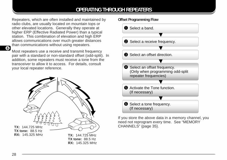
Repeaters, which are often installed and maintained byradio clubs, are usually located on mountain tops orother elevated locations. Generally they operate athigher ERP (Effective Radiated Power) than a typicalstation. This combination of elevation and high ERPallows communications over much greater distancesthan communications without using repeaters.
Most repeaters use a receive and transmit frequencypair with a standard or non-standard offset (odd-split). Inaddition, some repeaters must receive a tone from thetransceiver to allow it to access. For details, consultyour local repeater reference.
Offset Programming Flow
If you store the above data in a memory channel, youneed not reprogram every time. See “MEMORYCHANNELS” page 35.
Select a band.q
w
e
r
t
y
Select a receive frequency.
Select an offset direction.
Select an offset frequency. (Only when programming odd-split repeater frequencies)
Activate the Tone function. (If necessary)
Select a tone frequency. (If necessary)
TX: 144.725 MHzTX tone: 88.5 HzRX: 145.325 MHz
TX: 144.725 MHzTX tone: 88.5 HzRX: 145.325 MHz
29
6
PROGRAMMING OFFSETFirst select band A or B by pressing the left or right[BAND SEL] . To recall the sub-band next, press [F] ,then the same [BAND SEL] .
Selecting Offset Direction
Select whether the transmit frequency will be higher(+) or lower (–) than the receive frequency.
Press [F], [SHIFT] to switch the offset direction.• “+” or “–” appears to indicate which offset direction is
selected.
• To program –7.6 MHz offset on the TM-D700E (UHFonly), repeatedly press [F] , [SHIFT] until “=” appears.
If the offset transmit frequency falls outside theallowable range, transmitting is inhibited. Use one ofthe following methods to bring the transmit frequencywithin the band limits:
• Move the receive frequency further inside the band.
• Change the offset direction.
Note: While using an odd-split memory channel or transmitting, youcannot change the offset direction.
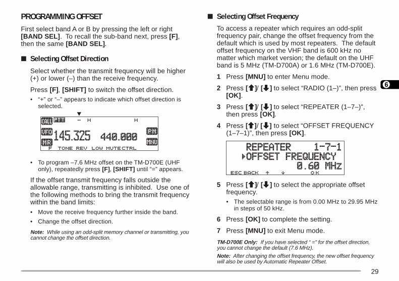
Selecting Offset Frequency
To access a repeater which requires an odd-splitfrequency pair, change the offset frequency from thedefault which is used by most repeaters. The defaultoffset frequency on the VHF band is 600 kHz nomatter which market version; the default on the UHFband is 5 MHz (TM-D700A) or 1.6 MHz (TM-D700E).
1 Press [MNU] to enter Menu mode.
2 Press [ccccc]/ [ddddd] to select “RADIO (1–)”, then press[OK] .
3 Press [ccccc]/ [ddddd] to select “REPEATER (1–7–)”,then press [OK] .
4 Press [ccccc]/ [ddddd] to select “OFFSET FREQUENCY(1–7–1)”, then press [OK] .
5 Press [ccccc]/ [ddddd] to select the appropriate offsetfrequency.• The selectable range is from 0.00 MHz to 29.95 MHz
in steps of 50 kHz.
6 Press [OK] to complete the setting.
7 Press [MNU] to exit Menu mode.
TM-D700E Only: If you have selected “ =” for the offset direction,you cannot change the default (7.6 MHz).
Note: After changing the offset frequency, the new offset frequencywill also be used by Automatic Repeater Offset.
30
6
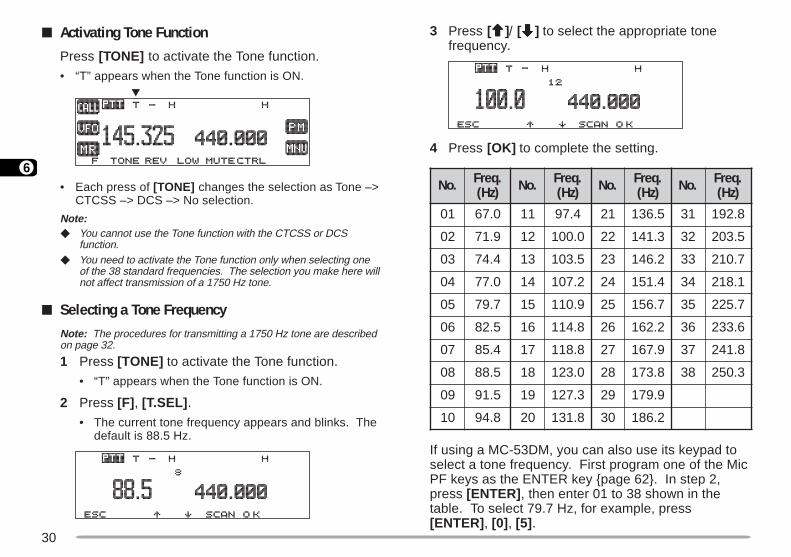
3 Press [ccccc]/ [ddddd] to select the appropriate tonefrequency.
4 Press [OK] to complete the setting.
If using a MC-53DM, you can also use its keypad toselect a tone frequency. First program one of the MicPF keys as the ENTER key page 62. In step 2,press [ENTER] , then enter 01 to 38 shown in thetable. To select 79.7 Hz, for example, press[ENTER] , [0] , [5] .
Activating Tone Function
Press [TONE] to activate the Tone function.
• “T” appears when the Tone function is ON.
• Each press of [TONE] changes the selection as Tone –>CTCSS –> DCS –> No selection.
Note: You cannot use the Tone function with the CTCSS or DCS
function. You need to activate the Tone function only when selecting one
of the 38 standard frequencies. The selection you make here willnot affect transmission of a 1750 Hz tone.
Selecting a Tone FrequencyNote: The procedures for transmitting a 1750 Hz tone are describedon page 32.
1 Press [TONE] to activate the Tone function.
• “T” appears when the Tone function is ON.
2 Press [F] , [T.SEL] .
• The current tone frequency appears and blinks. Thedefault is 88.5 Hz.
.oN .qerF)zH( .oN .qerF
)zH( .oN .qerF)zH( .oN .qerF
)zH(
10 0.76 11 4.79 12 5.631 13 8.291
20 9.17 21 0.001 22 3.141 23 5.302
30 4.47 31 5.301 32 2.641 33 7.012
40 0.77 41 2.701 42 4.151 43 1.812
50 7.97 51 9.011 52 7.651 53 7.522
60 5.28 61 8.411 62 2.261 63 6.332
70 4.58 71 8.811 72 9.761 73 8.142
80 5.88 81 0.321 82 8.371 83 3.052
90 5.19 91 3.721 92 9.971
01 8.49 02 8.131 03 2.681
31
6
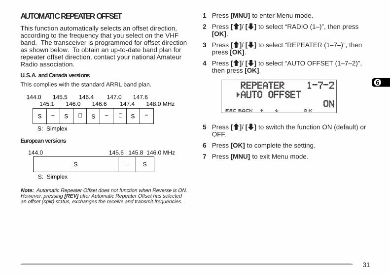
AUTOMATIC REPEATER OFFSETThis function automatically selects an offset direction,according to the frequency that you select on the VHFband. The transceiver is programmed for offset directionas shown below. To obtain an up-to-date band plan forrepeater offset direction, contact your national AmateurRadio association.
U.S.A. and Canada versions
This complies with the standard ARRL band plan.
European versions
Note: Automatic Repeater Offset does not function when Reverse is ON.However, pressing [REV] after Automatic Repeater Offset has selectedan offset (split) status, exchanges the receive and transmit frequencies.
1 Press [MNU] to enter Menu mode.
2 Press [ccccc]/ [ddddd] to select “RADIO (1–)”, then press[OK] .
3 Press [ccccc]/ [ddddd] to select “REPEATER (1–7–)”, thenpress [OK] .
4 Press [ccccc]/ [ddddd] to select “AUTO OFFSET (1–7–2)”,then press [OK] .
5 Press [ccccc]/ [ddddd] to switch the function ON (default) orOFF.
6 Press [OK] to complete the setting.
7 Press [MNU] to exit Menu mode.
+ −−− + SSSS
144.0 145.5 146.4 147.0 147.6145.1 146.0 146.6 147.4 148.0 MHz
S: Simplex
SS
S: Simplex
–
144.0 146.0 MHz145.8145.6
32
6
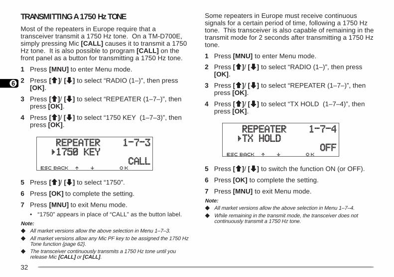
TRANSMITTING A 1750 Hz TONEMost of the repeaters in Europe require that atransceiver transmit a 1750 Hz tone. On a TM-D700E,simply pressing Mic [CALL] causes it to transmit a 1750Hz tone. It is also possible to program [CALL] on thefront panel as a button for transmitting a 1750 Hz tone.
1 Press [MNU] to enter Menu mode.
2 Press [ccccc]/ [ddddd] to select “RADIO (1–)”, then press[OK] .
3 Press [ccccc]/ [ddddd] to select “REPEATER (1–7–)”, thenpress [OK] .
4 Press [ccccc]/ [ddddd] to select “1750 KEY (1–7–3)”, thenpress [OK] .
5 Press [ccccc]/ [ddddd] to select “1750”.
6 Press [OK] to complete the setting.
7 Press [MNU] to exit Menu mode.• “1750” appears in place of “CALL” as the button label.
Note: All market versions allow the above selection in Menu 1–7–3. All market versions allow any Mic PF key to be assigned the 1750 Hz
Tone function page 62. The transceiver continuously transmits a 1750 Hz tone until you
release Mic [CALL] or [CALL] .
Some repeaters in Europe must receive continuoussignals for a certain period of time, following a 1750 Hztone. This transceiver is also capable of remaining in thetransmit mode for 2 seconds after transmitting a 1750 Hztone.
1 Press [MNU] to enter Menu mode.
2 Press [ccccc]/ [ddddd] to select “RADIO (1–)”, then press[OK] .
3 Press [ccccc]/ [ddddd] to select “REPEATER (1–7–)”, thenpress [OK] .
4 Press [ccccc]/ [ddddd] to select “TX HOLD (1–7–4)”, thenpress [OK] .
5 Press [ccccc]/ [ddddd] to switch the function ON (or OFF).
6 Press [OK] to complete the setting.
7 Press [MNU] to exit Menu mode.Note: All market versions allow the above selection in Menu 1–7–4. While remaining in the transmit mode, the transceiver does not
continuously transmit a 1750 Hz tone.
33
6
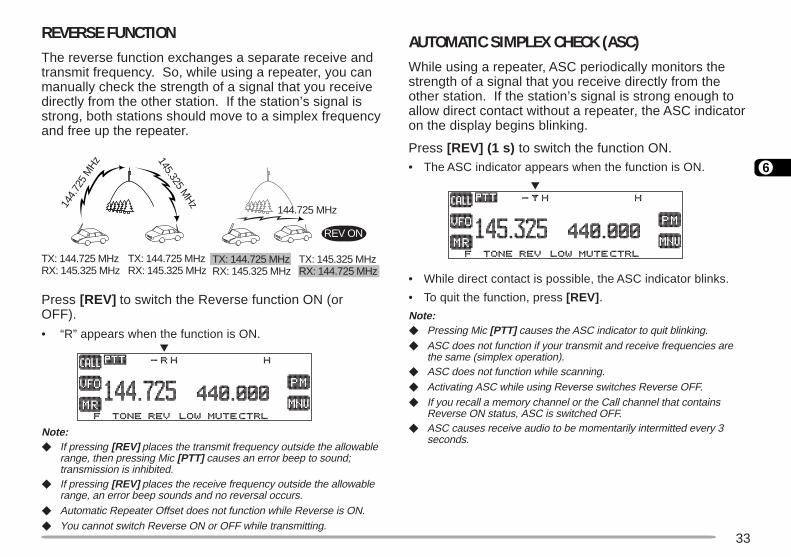
AUTOMATIC SIMPLEX CHECK (ASC)While using a repeater, ASC periodically monitors thestrength of a signal that you receive directly from theother station. If the station’s signal is strong enough toallow direct contact without a repeater, the ASC indicatoron the display begins blinking.
Press [REV] (1 s) to switch the function ON.• The ASC indicator appears when the function is ON.
• While direct contact is possible, the ASC indicator blinks.
• To quit the function, press [REV] .
Note: Pressing Mic [PTT] causes the ASC indicator to quit blinking. ASC does not function if your transmit and receive frequencies are
the same (simplex operation). ASC does not function while scanning. Activating ASC while using Reverse switches Reverse OFF. If you recall a memory channel or the Call channel that contains
Reverse ON status, ASC is switched OFF. ASC causes receive audio to be momentarily intermitted every 3
seconds.
REVERSE FUNCTIONThe reverse function exchanges a separate receive andtransmit frequency. So, while using a repeater, you canmanually check the strength of a signal that you receivedirectly from the other station. If the station’s signal isstrong, both stations should move to a simplex frequencyand free up the repeater.
Press [REV] to switch the Reverse function ON (orOFF).
• “R” appears when the function is ON.
Note: If pressing [REV] places the transmit frequency outside the allowable
range, then pressing Mic [PTT] causes an error beep to sound;transmission is inhibited.
If pressing [REV] places the receive frequency outside the allowablerange, an error beep sounds and no reversal occurs.
Automatic Repeater Offset does not function while Reverse is ON. You cannot switch Reverse ON or OFF while transmitting.
REV ON
144.
725
MHz
145.325 MHz
144.725 MHz
TX: 144.725 MHz TX: 144.725 MHzRX: 145.325 MHz RX: 145.325 MHz
TX: 144.725 MHz TX: 145.325 MHzRX: 145.325 MHz RX: 144.725 MHz

34
6
4 Press [OK] to program the identified frequency inplace of the currently set tone frequency.• The Tone function will be remained ON. You may press
[TONE] to switch the Tone function OFF.
• Press [ESC] if you do not want to program the identifiedfrequency.
• Press [SCAN] while the identified frequency is blinking,to resume scanning.
TONE FREQ. IDThis function scans through all tone frequencies toidentify the incoming tone frequency on a receivedsignal. You may use the function to find which tonefrequency is required by your local repeater.
1 Press [TONE] to switch ON the Tone function.
• “T” appears when the Tone function is ON.
2 Press [F], [T.SEL] .
• The current tone frequency appears and blinks.
3 Press [SCAN] to activate the Tone Freq. ID.“T SCAN” appears and blinks.
• Scan starts when signals are received.
• To reverse the scan direction, turn the Tuning controlclockwise (upward scan) or counterclockwise(downward scan). You can also press Mic [UP] / [DWN] .
• To quit the function, press [ESC] .
• When the tone frequency is identified, the identifiedfrequency appears and blinks.
35
7
MEMORY CHANNELS
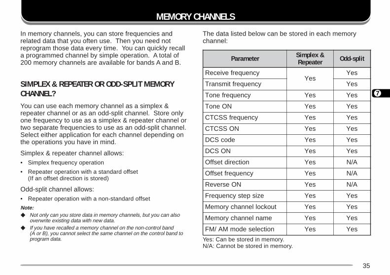
In memory channels, you can store frequencies andrelated data that you often use. Then you need notreprogram those data every time. You can quickly recalla programmed channel by simple operation. A total of200 memory channels are available for bands A and B.
SIMPLEX & REPEATER OR ODD-SPLIT MEMORYCHANNEL?You can use each memory channel as a simplex &repeater channel or as an odd-split channel. Store onlyone frequency to use as a simplex & repeater channel ortwo separate frequencies to use as an odd-split channel.Select either application for each channel depending onthe operations you have in mind.
Simplex & repeater channel allows:• Simplex frequency operation
• Repeater operation with a standard offset(If an offset direction is stored)
Odd-split channel allows:• Repeater operation with a non-standard offset
Note: Not only can you store data in memory channels, but you can also
overwrite existing data with new data. If you have recalled a memory channel on the non-control band
(A or B), you cannot select the same channel on the control band toprogram data.
The data listed below can be stored in each memorychannel:
Yes: Can be stored in memory.N/A: Cannot be stored in memory.
retemaraP &xelpmiSretaepeR tilps-ddO
ycneuqerfevieceRseY
seY
ycneuqerftimsnarT seY
ycneuqerfenoT seY seY
NOenoT seY seY
ycneuqerfSSCTC seY seY
NOSSCTC seY seY
edocSCD seY seY
NOSCD seY seY
noitceridtesffO seY A/N
ycneuqerftesffO seY A/N
NOesreveR seY A/N
ezispetsycneuqerF seY seY
tuokcollennahcyromeM seY seY
emanlennahcyromeM seY seY
noitcelesedomMA/MF seY seY
36
7
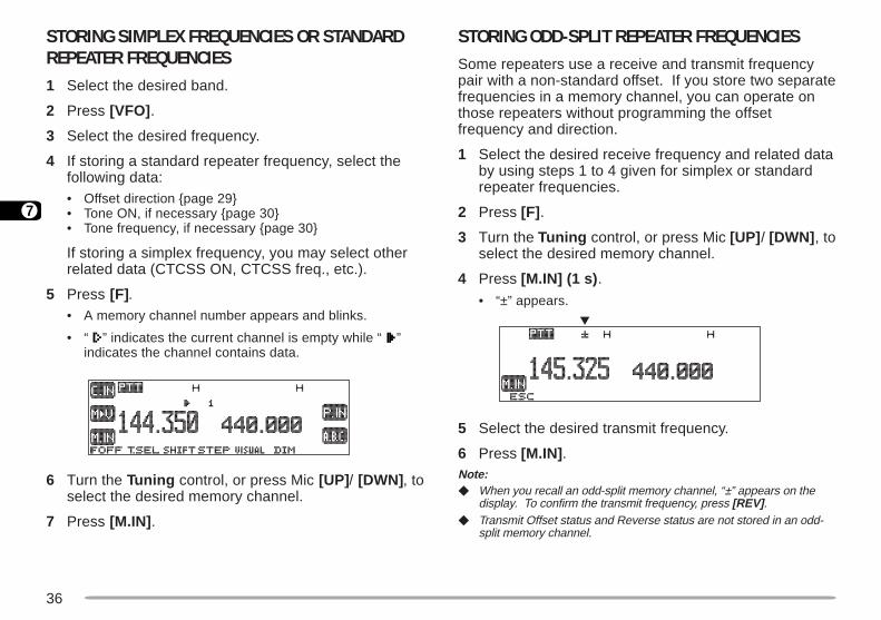
STORING ODD-SPLIT REPEATER FREQUENCIESSome repeaters use a receive and transmit frequencypair with a non-standard offset. If you store two separatefrequencies in a memory channel, you can operate onthose repeaters without programming the offsetfrequency and direction.
1 Select the desired receive frequency and related databy using steps 1 to 4 given for simplex or standardrepeater frequencies.
2 Press [F] .
3 Turn the Tuning control, or press Mic [UP] / [DWN] , toselect the desired memory channel.
4 Press [M.IN] (1 s) .
• “±” appears.
5 Select the desired transmit frequency.
6 Press [M.IN] .Note: When you recall an odd-split memory channel, “±” appears on the
display. To confirm the transmit frequency, press [REV] . Transmit Offset status and Reverse status are not stored in an odd-
split memory channel.
STORING SIMPLEX FREQUENCIES OR STANDARDREPEATER FREQUENCIES1 Select the desired band.
2 Press [VFO] .
3 Select the desired frequency.
4 If storing a standard repeater frequency, select thefollowing data:• Offset direction page 29• Tone ON, if necessary page 30• Tone frequency, if necessary page 30
If storing a simplex frequency, you may select otherrelated data (CTCSS ON, CTCSS freq., etc.).
5 Press [F].• A memory channel number appears and blinks.
• “ ” indicates the current channel is empty while “ ”indicates the channel contains data.
6 Turn the Tuning control, or press Mic [UP] / [DWN] , toselect the desired memory channel.
7 Press [M.IN] .

37
7
CLEARING A MEMORY CHANNELUse the following procedure to clear an individualmemory channel. Full Reset page 41 is a quick way toclear all memory channels.
1 Recall the desired memory channel.
2 Switch OFF the power to the transceiver.
3 Press [MHz] (Tuning control)+ POWER ON.
• A confirmation message appears.
• To quit clearing the memory channel, press [ESC] .
4 Press [OK] .Note: If you have recalled a memory channel on the non-control band (A or
B), you cannot select the same channel on the control band to clear. When in Channel Display mode, you cannot clear any memory
channel.
RECALLING A MEMORY CHANNEL1 Select band A or B.
2 Press [MR] to enter Memory Recall mode.
• The memory channel used last is recalled.
3 Turn the Tuning control, or press Mic [UP] / [DWN] , toselect the desired memory channel.
• You cannot recall an empty memory channel.
• To restore VFO mode, press [VFO] .
If using a MC-53DM, you can also use its keypad torecall a desired memory channel. First program one ofthe Mic PF keys as the ENTER key page 62. InMemory Recall mode press [ENTER], then enter thechannel number. To recall channel 3, for example, press[ENTER] , [0] , [0] , [3] .Note: When you recall an odd-split memory channel, “±” appears on the
display. Press [REV] to display the transmit frequency. After recalling a memory channel, you may program data such as
Tone or CTCSS. These settings, however, are cleared once youselect another channel or the VFO mode. To permanently store thedata, overwrite the channel contents page 36.
38
7
8 Repeat steps 6 and 7 to enter up to 8 digits.
9 Press [OK] to complete the setting.
10 Press [MNU] to exit Menu mode.
The keypad on the MC-53DM also is available to enteralphanumeric characters in step 6. See page 18.Note: You can also name the Program Scan page 52 and DTMF
page 60 channels, but you cannot name the Call channelpage 39.
You can assign names only to memory channels in which you havestored frequencies and related data.
The stored names can be overwritten by repeating steps 1 to 10. The stored names also are erased by clearing memory channels.
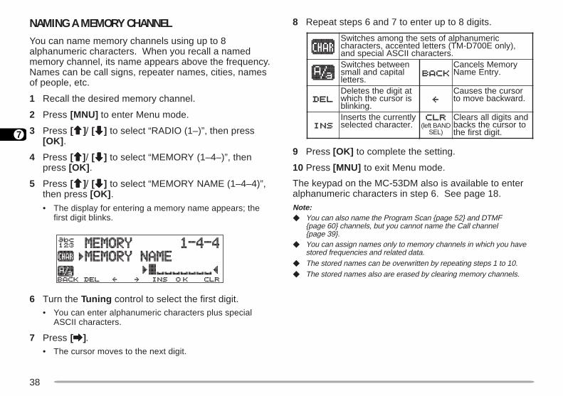
NAMING A MEMORY CHANNELYou can name memory channels using up to 8alphanumeric characters. When you recall a namedmemory channel, its name appears above the frequency.Names can be call signs, repeater names, cities, namesof people, etc.
1 Recall the desired memory channel.
2 Press [MNU] to enter Menu mode.
3 Press [ccccc]/ [ddddd] to select “RADIO (1–)”, then press[OK] .
4 Press [ccccc]/ [ddddd] to select “MEMORY (1–4–)”, thenpress [OK] .
5 Press [ccccc]/ [ddddd] to select “MEMORY NAME (1–4–4)”,then press [OK] .
• The display for entering a memory name appears; thefirst digit blinks.
6 Turn the Tuning control to select the first digit.• You can enter alphanumeric characters plus special
ASCII characters.
7 Press [aaaaa].• The cursor moves to the next digit.
ciremunahplafostesehtgnomasehctiwS,)ylnoE007D-MT(sretteldetnecca,sretcarahc
.sretcarahcIICSAlaicepsdnaneewtebsehctiwSlatipacdnallams
.srettel
yromeMslecnaC.yrtnEemaN
tatigidehtseteleDsirosrucehthcihw
.gniknilb
rosrucehtsesuaC.drawkcabevomot
yltnerrucehtstresnI.retcarahcdetceles DNABtfel(
)LES
dnastigidllasraelCotrosrucehtskcab
.tigidtsrifeht

39
7
CALL CHANNELThe Call channel can always be selected quickly nomatter what mode the transceiver is in. For instance,you may use the Call channel as an emergencychannel within your group. In this case, the Call/VFOscan page 54 will be useful.
The default frequency stored in the Call channel is144.000 MHz for the VHF band. The default on the UHFband is 440.000 MHz or 430.000 MHz depending on themarket versions. The Call channel can bereprogrammed either as a simplex & repeater or odd-split channel.
Note: Unlike channels 1 to 200 the call channel cannot be cleared.
Recalling the Call Channel
1 Select the desired band.
2 Press [CALL] to recall the Call channel.• “CALL” appears.
• To restore the previous mode, press [CALL] again.
Reprogramming the Call Channel
1 Select the desired band.
2 Press [VFO] .
3 Select the desired frequency and related data(Tone, CTCSS, etc.).• When you program the Call channel as an odd-split
channel, select a receive frequency.
4 Press [F] , [C.IN] .• The selected frequency and related data are stored
in the Call channel.
• The previous mode is restored.
• When programming as an odd-split channel, press[F] , [C.IN] (1 s) instead; “±” appears.
To also store a transmit frequency, proceed to thenext step.
5 Select the desired transmit frequency.
6 Press [C.IN] .• The transmit frequency is stored in the Call channel,
and the previous mode is restored.Note: Transmit Offset status and Reverse status are not stored in an
odd-split Call channel. To store data other than frequencies, select the data in step 3 not
step 5.
40
7
MEMORY-TO-VFO TRANSFERYou may sometimes want to search for other stations ora clear frequency, near the frequency stored in amemory channel or the Call channel. In this case firsttransfer the contents of a memory channel or the Callchannel to the VFO.
1 Recall the desired memory channel or the Callchannel.
2 Press [F] , [MsssssV] .• The entire contents of the memory channel or the Call
channel are copied to the VFO.Note: A transmit frequency from an odd-split memory channel or odd-split
Call channel is not transferred to the VFO. To transfer a transmitfrequency, press [REV] , then press [F] , [MsssssV].
Lockout status and memory names are not copied from a memorychannel to the VFO.
If you recall the Call channel in step 1, simply turning the TuningControl or pressing Mic [UP] / [DWN] also transfers the contents tothe VFO. The frequency, however, is changed by one step.
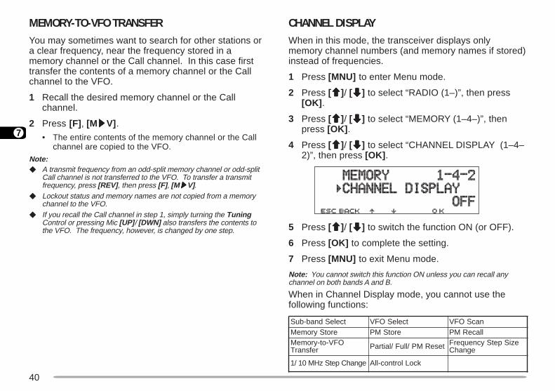
CHANNEL DISPLAYWhen in this mode, the transceiver displays onlymemory channel numbers (and memory names if stored)instead of frequencies.
1 Press [MNU] to enter Menu mode.
2 Press [ccccc]/ [ddddd] to select “RADIO (1–)”, then press[OK] .
3 Press [ccccc]/ [ddddd] to select “MEMORY (1–4–)”, thenpress [OK] .
4 Press [ccccc]/ [ddddd] to select “CHANNEL DISPLAY (1–4–2)”, then press [OK] .
5 Press [ccccc]/ [ddddd] to switch the function ON (or OFF).
6 Press [OK] to complete the setting.
7 Press [MNU] to exit Menu mode.
Note: You cannot switch this function ON unless you can recall anychannel on both bands A and B.
When in Channel Display mode, you cannot use thefollowing functions:
tceleSdnab-buS tceleSOFV nacSOFVerotSyromeM erotSMP llaceRMP
OFV-ot-yromeMrefsnarT teseRMP/lluF/laitraP eziSpetSycneuqerF
egnahC
egnahCpetSzHM01/1 kcoLlortnoc-llA
41
7
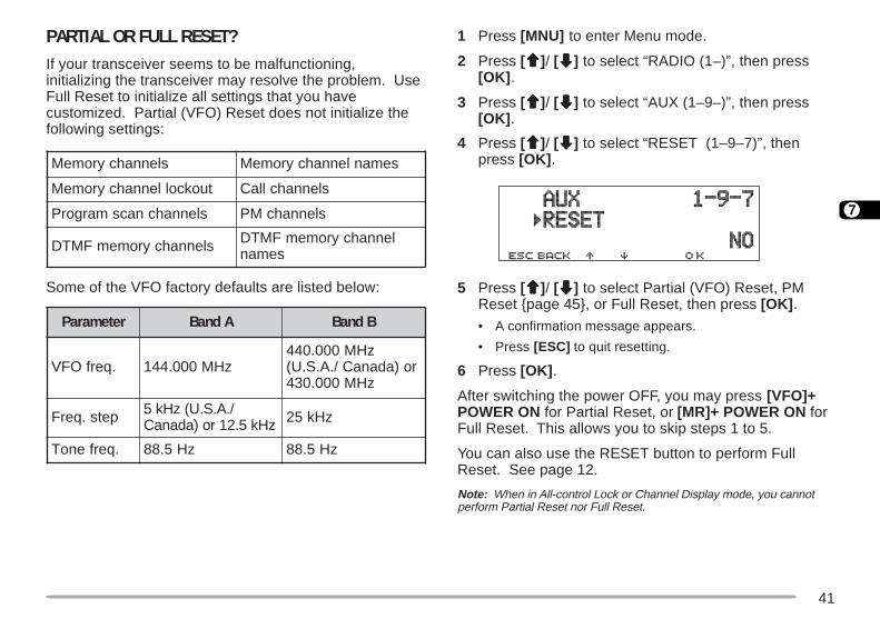
PARTIAL OR FULL RESET?If your transceiver seems to be malfunctioning,initializing the transceiver may resolve the problem. UseFull Reset to initialize all settings that you havecustomized. Partial (VFO) Reset does not initialize thefollowing settings:
Some of the VFO factory defaults are listed below:
1 Press [MNU] to enter Menu mode.
2 Press [ccccc]/ [ddddd] to select “RADIO (1–)”, then press[OK] .
3 Press [ccccc]/ [ddddd] to select “AUX (1–9–)”, then press[OK] .
4 Press [ccccc]/ [ddddd] to select “RESET (1–9–7)”, thenpress [OK] .
5 Press [ccccc]/ [ddddd] to select Partial (VFO) Reset, PMReset page 45, or Full Reset, then press [OK] .
• A confirmation message appears.
• Press [ESC] to quit resetting.
6 Press [OK] .
After switching the power OFF, you may press [VFO]+POWER ON for Partial Reset, or [MR]+ POWER ON forFull Reset. This allows you to skip steps 1 to 5.
You can also use the RESET button to perform FullReset. See page 12.
Note: When in All-control Lock or Channel Display mode, you cannotperform Partial Reset nor Full Reset.
retemaraP AdnaB BdnaB
.qerfOFV zHM000.441zHM000.044
ro)adanaC/.A.S.U(zHM000.034
pets.qerF /.A.S.U(zHk5zHk5.21ro)adanaC zHk52
.qerfenoT zH5.88 zH5.88
slennahcyromeM semanlennahcyromeM
tuokcollennahcyromeM slennahcllaC
slennahcnacsmargorP slennahcMP
slennahcyromemFMTD lennahcyromemFMTDseman

42
8
PROGRAMMABLE MEMORY (PM)
Programmable Memory (PM) stores virtually all settingscurrently set on the transceiver. This transceiverprovides 5 PM channels to store 5 sets of transceiverconfigurations. Later you can quickly recall one of these,depending on the operations in your mind or theoperating environment.
PROGRAMMABLE INFORMATIONThe following settings can be separately stored for bandA and B:
The following settings are shared by both band A and B:
ycneuqerfOFV edomOFV
edomllaceRyromeM edomlennahCllaC
noitceridtesffO ycneuqerftesffO
NOesreveR kcehCxelpmiScitamotuA
NOenoT ycneuqerfenoT
NOSSCTC ycneuqerfSSCTC
NOSCD edocSCD
timilycneuqerfreppU)OFVelbammargorProf(
timilycneuqerfrewoL)OFVelbammargorProf(
ezispetsycneuqerF edomMA/MF
noitaivedXTworran/ediW 1
1 TM-D700E only
1 The menu items listed below will not be stored:• 1–4–1, Auto PM Channel Store• 1–4–3, Memory Channel Lockout• 1–4–4, Memory channel name• 1–5–1, DTMF Number Store• 1–6–3, Time• 1–6–4, Date• 1–7–6, Repeater function• 1–9–5, COM port• 1–9–7, Reset• 1–A–3, Remote Control• 2–8, SSTV mode• 3–4, My position• 3–9, Status text• 4–4, Sky Command mode
2 U.S.A./ Canada only
dnabXT dnablortnoC
rewoptuptuotimsnarT egnahCdnaBotuA
remmiDyalpsiD snoitcelesunemehtfoynaM)–1(OIDARrednu 1
snoitcelesunemehtfotsoM)–2(VTSSrednu 1
snoitcelesunemehtfotsoM)–3(SRPArednu 1
snoitcelesunemehtfotsoM)–4(DNAMMOCYKSrednu 2,1
43
8
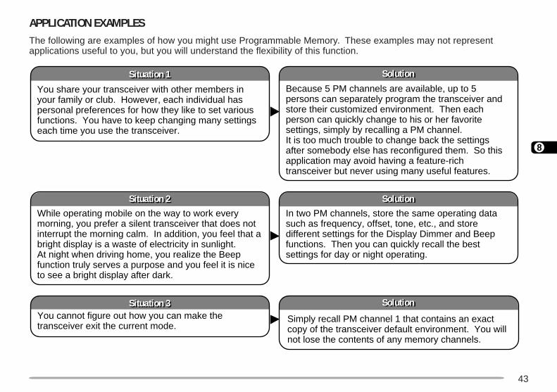
APPLICATION EXAMPLESThe following are examples of how you might use Programmable Memory. These examples may not representapplications useful to you, but you will understand the flexibility of this function.
SolutionSolution
SolutionSolution
SolutionSolution
Situation 3Situation 3
Situation 2Situation 2
Situation 1Situation 1
You share your transceiver with other members in your family or club. However, each individual has personal preferences for how they like to set various functions. You have to keep changing many settings each time you use the transceiver.
Because 5 PM channels are available, up to 5 persons can separately program the transceiver and store their customized environment. Then each person can quickly change to his or her favorite settings, simply by recalling a PM channel. It is too much trouble to change back the settings after somebody else has reconfigured them. So this application may avoid having a feature-rich transceiver but never using many useful features.
While operating mobile on the way to work every morning, you prefer a silent transceiver that does not interrupt the morning calm. In addition, you feel that a bright display is a waste of electricity in sunlight. At night when driving home, you realize the Beep function truly serves a purpose and you feel it is nice to see a bright display after dark.
In two PM channels, store the same operating data such as frequency, offset, tone, etc., and store different settings for the Display Dimmer and Beep functions. Then you can quickly recall the best settings for day or night operating.
You cannot figure out how you can make the transceiver exit the current mode.
Simply recall PM channel 1 that contains an exact copy of the transceiver default environment. You will not lose the contents of any memory channels.
44
8
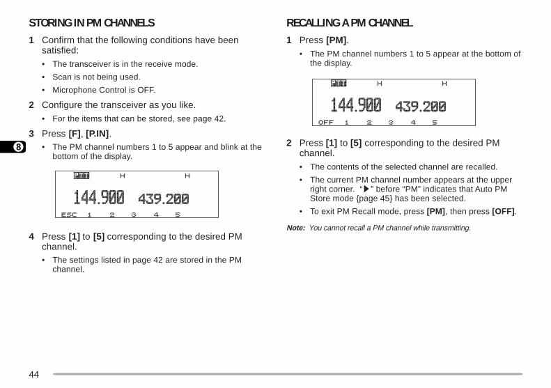
STORING IN PM CHANNELS1 Confirm that the following conditions have been
satisfied:
• The transceiver is in the receive mode.
• Scan is not being used.
• Microphone Control is OFF.
2 Configure the transceiver as you like.
• For the items that can be stored, see page 42.
3 Press [F] , [P.IN] .• The PM channel numbers 1 to 5 appear and blink at the
bottom of the display.
4 Press [1] to [5] corresponding to the desired PMchannel.• The settings listed in page 42 are stored in the PM
channel.
RECALLING A PM CHANNEL1 Press [PM] .
• The PM channel numbers 1 to 5 appear at the bottom ofthe display.
2 Press [1] to [5] corresponding to the desired PMchannel.
• The contents of the selected channel are recalled.
• The current PM channel number appears at the upperright corner. “s” before “PM” indicates that Auto PMStore mode page 45 has been selected.
• To exit PM Recall mode, press [PM] , then press [OFF].
Note: You cannot recall a PM channel while transmitting.
45
8
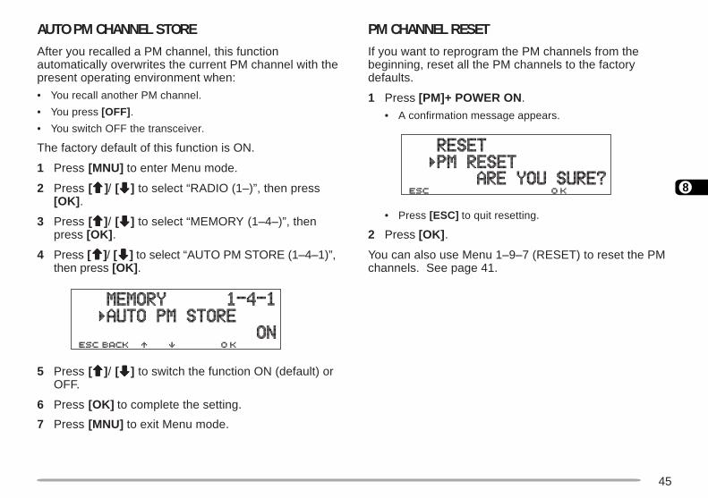
AUTO PM CHANNEL STOREAfter you recalled a PM channel, this functionautomatically overwrites the current PM channel with thepresent operating environment when:
• You recall another PM channel.
• You press [OFF] .
• You switch OFF the transceiver.
The factory default of this function is ON.
1 Press [MNU] to enter Menu mode.
2 Press [ccccc]/ [ddddd] to select “RADIO (1–)”, then press[OK] .
3 Press [ccccc]/ [ddddd] to select “MEMORY (1–4–)”, thenpress [OK] .
4 Press [ccccc]/ [ddddd] to select “AUTO PM STORE (1–4–1)”,then press [OK] .
5 Press [ccccc]/ [ddddd] to switch the function ON (default) orOFF.
6 Press [OK] to complete the setting.
7 Press [MNU] to exit Menu mode.
PM CHANNEL RESETIf you want to reprogram the PM channels from thebeginning, reset all the PM channels to the factorydefaults.
1 Press [PM]+ POWER ON .
• A confirmation message appears.
• Press [ESC] to quit resetting.
2 Press [OK] .
You can also use Menu 1–9–7 (RESET) to reset the PMchannels. See page 41.
46
9
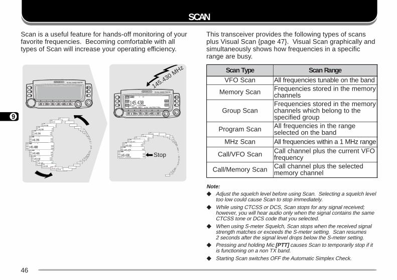
SCAN
This transceiver provides the following types of scansplus Visual Scan page 47. Visual Scan graphically andsimultaneously shows how frequencies in a specificrange are busy.
Note: Adjust the squelch level before using Scan. Selecting a squelch level
too low could cause Scan to stop immediately. While using CTCSS or DCS, Scan stops for any signal received;
however, you will hear audio only when the signal contains the sameCTCSS tone or DCS code that you selected.
When using S-meter Squelch, Scan stops when the received signalstrength matches or exceeds the S-meter setting. Scan resumes2 seconds after the signal level drops below the S-meter setting.
Pressing and holding Mic [PTT] causes Scan to temporarily stop if itis functioning on a non TX band.
Starting Scan switches OFF the Automatic Simplex Check.
Scan is a useful feature for hands-off monitoring of yourfavorite frequencies. Becoming comfortable with alltypes of Scan will increase your operating efficiency.
145.430 MHz
Stop
epyTnacS egnaRnacSnacSOFV dnabehtnoelbanutseicneuqerfllA
nacSyromeM yromemehtniderotsseicneuqerFslennahc
nacSpuorGyromemehtniderotsseicneuqerF
ehtotgnolebhcihwslennahcpuorgdeificeps
nacSmargorP egnarehtniseicneuqerfllAdnabehtnodetceles
nacSzHM egnarzHM1anihtiwseicneuqerfllA
nacSOFV/llaC OFVtnerrucehtsulplennahcllaCycneuqerf
nacSyromeM/llaC detcelesehtsulplennahcllaClennahcyromem
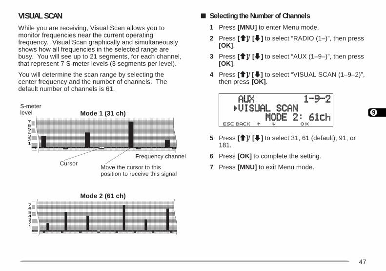
47
9
VISUAL SCANWhile you are receiving, Visual Scan allows you tomonitor frequencies near the current operatingfrequency. Visual Scan graphically and simultaneouslyshows how all frequencies in the selected range arebusy. You will see up to 21 segments, for each channel,that represent 7 S-meter levels (3 segments per level).
You will determine the scan range by selecting thecenter frequency and the number of channels. Thedefault number of channels is 61.
Selecting the Number of Channels
1 Press [MNU] to enter Menu mode.
2 Press [ccccc]/ [ddddd] to select “RADIO (1–)”, then press[OK] .
3 Press [ccccc]/ [ddddd] to select “AUX (1–9–)”, then press[OK] .
4 Press [ccccc]/ [ddddd] to select “VISUAL SCAN (1–9–2)”,then press [OK] .
5 Press [ccccc]/ [ddddd] to select 31, 61 (default), 91, or181.
6 Press [OK] to complete the setting.
7 Press [MNU] to exit Menu mode.
7
123456
7
123456
S-meterlevel Mode 1 (31 ch)
CursorFrequency channel
Move the cursor to thisposition to receive this signal
Mode 2 (61 ch)
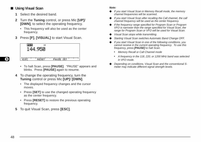
48
9
Note: If you start Visual Scan in Memory Recall mode, the memory
channel frequencies will be scanned. If you start Visual Scan after recalling the Call channel, the call
channel frequency will be used as the center frequency. If the frequency range specified for Program Scan or Program
VFO is narrower than the range specified for Visual Scan, therange for Program Scan or VFO will be used for Visual Scan.
Visual Scan stops while transmitting. Starting Visual Scan switches Automatic Band Change OFF. If you start Visual Scan in one of the following conditions, you
cannot receive in the current operating frequency. To use thisfrequency, press [PAUSE] to halt Scan.
• Memory Recall or Call Channel mode
• A frequency in the 118, 220, or 1200 MHz band was selectedin VFO mode.
Depending on conditions, Visual Scan and the conventional S-meter may indicate different signal strength levels.
Using Visual Scan
1 Select the desired band.
2 Turn the Tuning control, or press Mic [UP] /[DWN] , to select the operating frequency.• This frequency will also be used as the center
frequency.
3 Press [F] , [VISUAL] to start Visual Scan.
• To halt Scan, press [PAUSE] . “PAUSE” appears andblinks. Press [PAUSE] again to resume.
4 To change the operating frequency, turn theTuning control or press Mic [UP] / [DWN] .• The displayed frequency changes and the cursor
moves.
• Press [SET] to use the changed operating frequencyas the center frequency.
• Press [RESET] to restore the previous operatingfrequency.
5 To quit Visual Scan, press [ESC] .
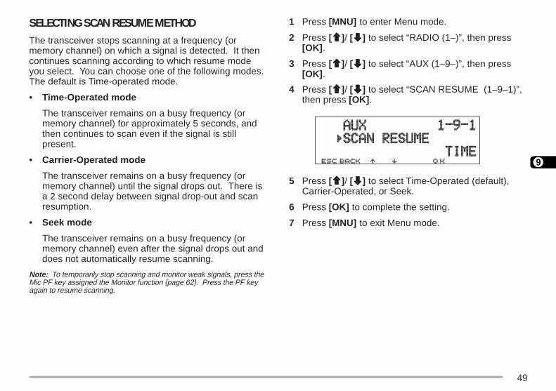
49
9
1 Press [MNU] to enter Menu mode.
2 Press [ccccc]/ [ddddd] to select “RADIO (1–)”, then press[OK] .
3 Press [ccccc]/ [ddddd] to select “AUX (1–9–)”, then press[OK] .
4 Press [ccccc]/ [ddddd] to select “SCAN RESUME (1–9–1)”,then press [OK] .
5 Press [ccccc]/ [ddddd] to select Time-Operated (default),Carrier-Operated, or Seek.
6 Press [OK] to complete the setting.
7 Press [MNU] to exit Menu mode.
SELECTING SCAN RESUME METHODThe transceiver stops scanning at a frequency (ormemory channel) on which a signal is detected. It thencontinues scanning according to which resume modeyou select. You can choose one of the following modes.The default is Time-operated mode.
• Time-Operated mode
The transceiver remains on a busy frequency (ormemory channel) for approximately 5 seconds, andthen continues to scan even if the signal is stillpresent.
• Carrier-Operated mode
The transceiver remains on a busy frequency (ormemory channel) until the signal drops out. There isa 2 second delay between signal drop-out and scanresumption.
• Seek mode
The transceiver remains on a busy frequency (ormemory channel) even after the signal drops out anddoes not automatically resume scanning.
Note: To temporarily stop scanning and monitor weak signals, press theMic PF key assigned the Monitor function page 62. Press the PF keyagain to resume scanning.
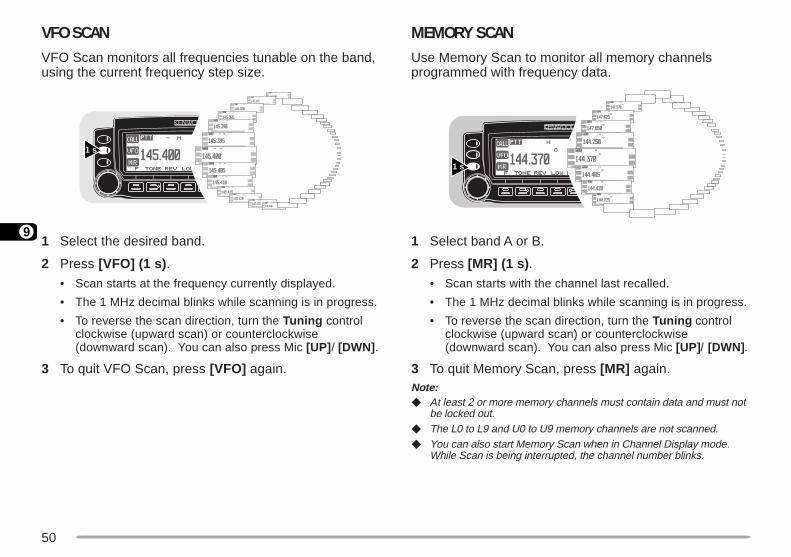
50
9
MEMORY SCANUse Memory Scan to monitor all memory channelsprogrammed with frequency data.
1 Select band A or B.
2 Press [MR] (1 s) .
• Scan starts with the channel last recalled.
• The 1 MHz decimal blinks while scanning is in progress.
• To reverse the scan direction, turn the Tuning controlclockwise (upward scan) or counterclockwise(downward scan). You can also press Mic [UP] / [DWN].
3 To quit Memory Scan, press [MR] again.Note: At least 2 or more memory channels must contain data and must not
be locked out. The L0 to L9 and U0 to U9 memory channels are not scanned. You can also start Memory Scan when in Channel Display mode.
While Scan is being interrupted, the channel number blinks.
VFO SCANVFO Scan monitors all frequencies tunable on the band,using the current frequency step size.
1 Select the desired band.
2 Press [VFO] (1 s) .
• Scan starts at the frequency currently displayed.
• The 1 MHz decimal blinks while scanning is in progress.
• To reverse the scan direction, turn the Tuning controlclockwise (upward scan) or counterclockwise(downward scan). You can also press Mic [UP] / [DWN] .
3 To quit VFO Scan, press [VFO] again.
1 s
1 s

51
9
Locking Out a Memory Channel
Select memory channels that you prefer not tomonitor while scanning.
1 Recall the desired memory channel.
2 Press [MNU] to enter Menu mode.
3 Press [ccccc]/ [ddddd] to select “RADIO (1–)”, then press[OK] .
4 Press [ccccc]/ [ddddd] to select “MEMORY (1–4–)”, thenpress [OK] .
5 Press [ccccc]/ [ddddd] to select “LOCKOUT (1–4–3)”,then press [OK] .
6 Press [ccccc]/ [ddddd] to switch Lockout ON (or OFF).
7 Press [OK] to complete the setting.
8 Press [MNU] to exit Menu mode.
• A star appears to indicate the channel has beenlocked out.
Note: The L0 to L9 and U0 to U9 memory channels cannot belocked out.
GROUP SCANFor the purpose of Group Scan, the 200 memorychannels are divided into 10 groups, with each groupcontaining 20 channels. Group Scan monitors only the20 channels which belong to the specified group. Thechannels are grouped as below:
1 Recall one of the memory channels in the desiredgroup.
2 Press [MHz] (Tuning control) (1 s).• Scan starts with the channel last recalled.
• The 1 MHz decimal blinks while scanning is in progress.
• To reverse the scan direction, turn the Tuning controlclockwise (upward scan) or counterclockwise(downward scan). You can also press Mic [UP] / [DWN].
3 To quit Group Scan, press [MHz] again.Note: At least 2 or more memory channels in the specified group must
contain data and must not be locked out. You can also start Group Scan when in Channel Display mode.
While Scan is being interrupted, the channel number blinks.
02~1.soN 021~101.soN
04~12.soN 041~121.soN
06~14.soN 061~141.soN
08~16.soN 081~161.soN
001~18.soN 002~181.soN

52
9
6 Press [M.IN] .• The lower limit is stored in the channel.
7 Select the desired frequency as the upper limit.
8 Press [F] .
9 Turn the Tuning control, or press Mic [UP] /[DWN] , to select a matching channel in the rangeU0 to U9.
• If you have selected for example L3 in step 5, selectU3.
10 Press [M.IN] .• The upper limit is stored in the channel.
To confirm the stored scan limits, press [MR] , thenselect the L and U channels.Note: The lower limit must be lower in frequency than the upper limit. The lower and upper frequency step sizes must be equal. The lower and upper limits must be selected on the same band.
PROGRAM SCANProgram Scan is identical with VFO Scan except thatyou select the frequency range of the scan.
Setting Scan Limits
You can store up to 10 scan ranges in memorychannels L0/U0 to L9/U9.
1 Select the desired band.
2 Press [VFO] .
3 Select the desired frequency as the lower limit.
4 Press [F] .• A memory channel number appears and blinks.
5 Turn the Tuning control, or press Mic [UP] /[DWN] , to select a channel in the range L0 to L9.
1 s

53
9
Using Program Scan
1 Select the appropriate band.
2 Press [VFO] .
3 Select a frequency equal to or between theprogrammed scan limits.
4 Press [VFO] (1 s) .• Scan starts at the frequency currently displayed.
• The 1 MHz decimal blinks while scanning is inprogress.
• To reverse the scan direction, turn the Tuningcontrol clockwise (upward scan) or counterclockwise(downward scan). You can also press Mic [UP] /[DWN] .
5 To quit Program Scan, press [VFO] again.Note: If the step size of the current VFO frequency differs from that of
the programmed frequencies, VFO scan starts instead ofProgram Scan.
If the step size differs between the lower limit and the upper limit,VFO scan starts instead of Program Scan.
If the current VFO frequency is within more than oneprogrammed scan range, the range stored in the smallestchannel number is used.
MHz SCANMHz Scan monitors a 1 MHz segment of the band, usingthe current frequency step size. The current 1 MHz digitdetermines the limits of the scan. For example, if thecurrent frequency is 145.400 MHz, then the scan rangewould be from 145.000 MHz to 145.995 MHz. The exactupper limit depends on the current frequency step size.
1 Select the desired band.
2 Press [VFO] to select VFO mode.
3 Select a frequency within the desired 1 MHzsegment.
4 Press [MHz] (Tuning control) (1 s).• Scan starts at the frequency currently displayed.
• The 1 MHz decimal blinks while scanning is in progress.
• To reverse the scan direction, turn the Tuning controlclockwise (upward scan) or counterclockwise(downward scan). You can also press Mic [UP] / [DWN].
5 To quit MHz Scan, press [MHz] again.
1 s

54
9
CALL/VFO SCANUse Call/VFO Scan to monitor both the Call channel andthe current VFO frequency on the selected band.
1 Select the desired band.
2 Press [VFO] .
3 Select the desired frequency.
4 Press [CALL] (1 s) to start Call/VFO Scan.
• The 1 MHz decimal blinks while scanning is in progress.
5 To quit Call/VFO Scan, press [CALL] again.
CALL/MEMORY SCANUse Call/Memory Scan to monitor both the Call channeland the desired memory channel.
1 Recall the desired memory channel.
2 Press [CALL] (1 s) to start Call/Memory Scan.
• The 1 MHz decimal blinks while scanning is in progress.
• The Call channel on the same band as of the selectedmemory channel is used for Scan.
3 To quit Call/Memory Scan, press [CALL] again.
Note: The memory channel last used is scanned even if it has beenlocked out.
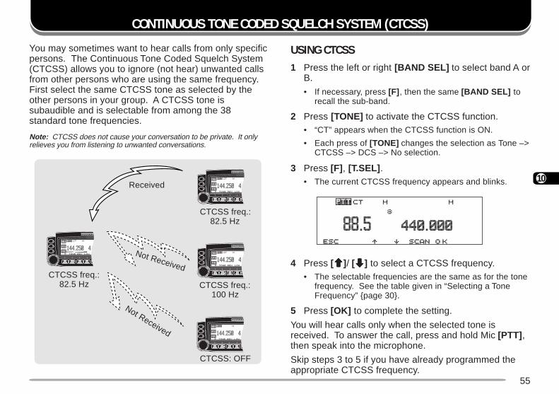
55
10
CONTINUOUS TONE CODED SQUELCH SYSTEM (CTCSS)
You may sometimes want to hear calls from only specificpersons. The Continuous Tone Coded Squelch System(CTCSS) allows you to ignore (not hear) unwanted callsfrom other persons who are using the same frequency.First select the same CTCSS tone as selected by theother persons in your group. A CTCSS tone issubaudible and is selectable from among the 38standard tone frequencies.
Note: CTCSS does not cause your conversation to be private. It onlyrelieves you from listening to unwanted conversations.
USING CTCSS1 Press the left or right [BAND SEL] to select band A or
B.
• If necessary, press [F] , then the same [BAND SEL] torecall the sub-band.
2 Press [TONE] to activate the CTCSS function.• “CT” appears when the CTCSS function is ON.
• Each press of [TONE] changes the selection as Tone –>CTCSS –> DCS –> No selection.
3 Press [F] , [T.SEL] .• The current CTCSS frequency appears and blinks.
4 Press [ccccc]/ [ddddd] to select a CTCSS frequency.• The selectable frequencies are the same as for the tone
frequency. See the table given in “Selecting a ToneFrequency” page 30.
5 Press [OK] to complete the setting.
You will hear calls only when the selected tone isreceived. To answer the call, press and hold Mic [PTT] ,then speak into the microphone.
Skip steps 3 to 5 if you have already programmed theappropriate CTCSS frequency.
CTCSS freq.:82.5 Hz
CTCSS freq.:82.5 Hz CTCSS freq.:
100 Hz
CTCSS: OFF
Received
Not Received
Not Received
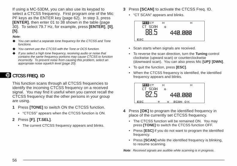
56
10
3 Press [SCAN] to activate the CTCSS Freq. ID.• “CT SCAN” appears and blinks.
• Scan starts when signals are received.
• To reverse the scan direction, turn the Tuning controlclockwise (upward scan) or counterclockwise(downward scan). You can also press Mic [UP] / [DWN] .
• To quit the function, press [ESC] .
• When the CTCSS frequency is identified, the identifiedfrequency appears and blinks.
4 Press [OK] to program the identified frequency inplace of the currently set CTCSS frequency.
• The CTCSS function will be remained ON. You maypress [TONE] to switch the CTCSS function OFF.
• Press [ESC] if you do not want to program the identifiedfrequency.
• Press [SCAN] while the identified frequency is blinking,to resume scanning.
Note : Received signals are audible while scanning is in progress.
If using a MC-53DM, you can also use its keypad toselect a CTCSS frequency. First program one of the MicPF keys as the ENTER key page 62. In step 3, press[ENTER] , then enter 01 to 38 shown in the table page30. To select 79.7 Hz, for example, press [ENTER] , [0],[5] .Note: You can select a separate tone frequency for the CTCSS and Tone
functions. You cannot use the CTCSS with the Tone or DCS function. If you select a high tone frequency, receiving audio or noise that
contains the same frequency portions may cause CTCSS to functionincorrectly. To prevent noise from causing this problem, select anappropriate noise squelch level page 20.
CTCSS FREQ. IDThis function scans through all CTCSS frequencies toidentify the incoming CTCSS frequency on a receivedsignal. You may find it useful when you cannot recall theCTCSS frequency that the other persons in your groupare using.
1 Press [TONE] to switch ON the CTCSS function.
• “CTCSS” appears when the CTCSS function is ON.
2 Press [F], [T.SEL] .
• The current CTCSS frequency appears and blinks.
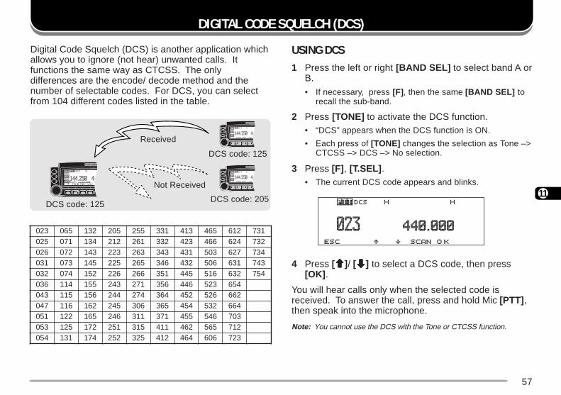
57
11
DIGITAL CODE SQUELCH (DCS)
USING DCS1 Press the left or right [BAND SEL] to select band A or
B.
• If necessary, press [F] , then the same [BAND SEL] torecall the sub-band.
2 Press [TONE] to activate the DCS function.• “DCS” appears when the DCS function is ON.
• Each press of [TONE] changes the selection as Tone –>CTCSS –> DCS –> No selection.
3 Press [F] , [T.SEL] .• The current DCS code appears and blinks.
4 Press [ccccc]/ [ddddd] to select a DCS code, then press[OK] .
You will hear calls only when the selected code isreceived. To answer the call, press and hold Mic [PTT] ,then speak into the microphone.
Note: You cannot use the DCS with the Tone or CTCSS function.
320 560 231 502 552 133 314 564 216 137520 170 431 212 162 233 324 664 426 237620 270 341 322 362 343 134 305 726 437130 370 541 522 562 643 234 605 136 347230 470 251 622 662 153 544 615 236 457630 411 551 342 172 653 644 325 456340 511 651 442 472 463 254 625 266740 611 261 542 603 563 454 235 466150 221 561 642 113 173 554 645 307350 521 271 152 513 114 264 565 217450 131 471 252 523 214 464 606 327
Digital Code Squelch (DCS) is another application whichallows you to ignore (not hear) unwanted calls. Itfunctions the same way as CTCSS. The onlydifferences are the encode/ decode method and thenumber of selectable codes. For DCS, you can selectfrom 104 different codes listed in the table.
Not Received
Received
DCS code: 125
DCS code: 125
DCS code: 205
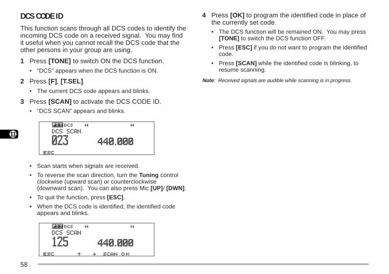
58
11
4 Press [OK] to program the identified code in place ofthe currently set code.• The DCS function will be remained ON. You may press
[TONE] to switch the DCS function OFF.
• Press [ESC] if you do not want to program the identifiedcode.
• Press [SCAN] while the identified code is blinking, toresume scanning.
Note : Received signals are audible while scanning is in progress.
DCS CODE IDThis function scans through all DCS codes to identify theincoming DCS code on a received signal. You may findit useful when you cannot recall the DCS code that theother persons in your group are using.
1 Press [TONE] to switch ON the DCS function.
• “DCS” appears when the DCS function is ON.
2 Press [F], [T.SEL] .
• The current DCS code appears and blinks.
3 Press [SCAN] to activate the DCS CODE ID.• “DCS SCAN” appears and blinks.
• Scan starts when signals are received.
• To reverse the scan direction, turn the Tuning controlclockwise (upward scan) or counterclockwise(downward scan). You can also press Mic [UP] / [DWN] .
• To quit the function, press [ESC] .
• When the DCS code is identified, the identified codeappears and blinks.
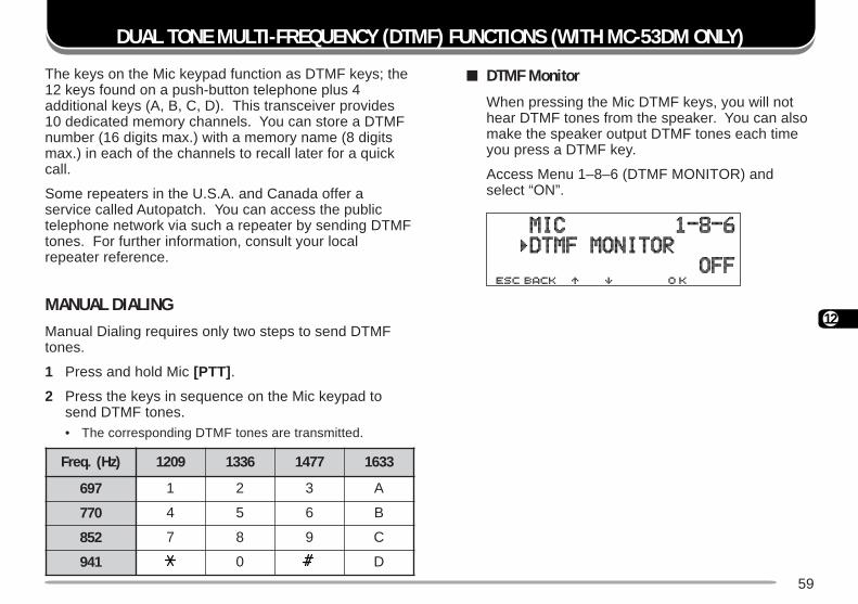
59
12
DUAL TONE MULTI-FREQUENCY (DTMF) FUNCTIONS (WITH MC-53DM ONLY)
The keys on the Mic keypad function as DTMF keys; the12 keys found on a push-button telephone plus 4additional keys (A, B, C, D). This transceiver provides10 dedicated memory channels. You can store a DTMFnumber (16 digits max.) with a memory name (8 digitsmax.) in each of the channels to recall later for a quickcall.
Some repeaters in the U.S.A. and Canada offer aservice called Autopatch. You can access the publictelephone network via such a repeater by sending DTMFtones. For further information, consult your localrepeater reference.
MANUAL DIALINGManual Dialing requires only two steps to send DTMFtones.
1 Press and hold Mic [PTT] .
2 Press the keys in sequence on the Mic keypad tosend DTMF tones.• The corresponding DTMF tones are transmitted.
DTMF Monitor
When pressing the Mic DTMF keys, you will nothear DTMF tones from the speaker. You can alsomake the speaker output DTMF tones each timeyou press a DTMF key.
Access Menu 1–8–6 (DTMF MONITOR) andselect “ON”.
)zH(.qerF 9021 6331 7741 3361
796 1 2 3 A
077 4 5 6 B
258 7 8 9 C
149 0 D
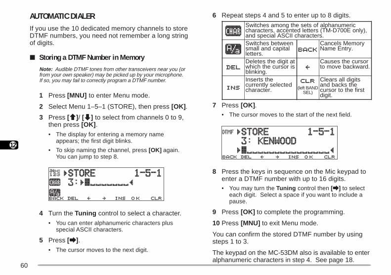
60
12
6 Repeat steps 4 and 5 to enter up to 8 digits.
7 Press [OK] .• The cursor moves to the start of the next field.
8 Press the keys in sequence on the Mic keypad toenter a DTMF number with up to 16 digits.• You may turn the Tuning control then [aaaaa] to select
each digit. Select a space if you want to include apause.
9 Press [OK] to complete the programming.
10 Press [MNU] to exit Menu mode.
You can confirm the stored DTMF number by usingsteps 1 to 3.
The keypad on the MC-53DM also is available to enteralphanumeric characters in step 4. See page 18.
AUTOMATIC DIALERIf you use the 10 dedicated memory channels to storeDTMF numbers, you need not remember a long stringof digits.
Storing a DTMF Number in MemoryNote: Audible DTMF tones from other transceivers near you (orfrom your own speaker) may be picked up by your microphone.If so, you may fail to correctly program a DTMF number.
1 Press [MNU] to enter Menu mode.
2 Select Menu 1–5–1 (STORE), then press [OK] .
3 Press [ccccc]/ [ddddd] to select from channels 0 to 9,then press [OK] .
• The display for entering a memory nameappears; the first digit blinks.
• To skip naming the channel, press [OK] again.You can jump to step 8.
4 Turn the Tuning control to select a character.
• You can enter alphanumeric characters plusspecial ASCII characters.
5 Press [aaaaa].• The cursor moves to the next digit.
ciremunahplafostesehtgnomasehctiwS,)ylnoE007D-MT(sretteldetnecca,sretcarahc
.sretcarahcIICSAlaicepsdnaneewtebsehctiwSlatipacdnallams
.srettel
yromeMslecnaC.yrtnEemaN
tatigidehtseteleDsirosrucehthcihw
.gniknilb
rosrucehtsesuaC.drawkcabevomot
ehtstresnIdetcelesyltnerruc
.retcarahc DNABtfel()LES
stigidllasraelCehtskcabdna
tsrifehtotrosruc.tigid
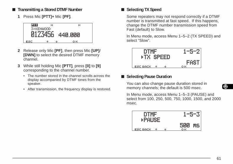
61
12
Selecting TX Speed
Some repeaters may not respond correctly if a DTMFnumber is transmitted at fast speed. If this happens,change the DTMF number transmission speed fromFast (default) to Slow.
In Menu mode, access Menu 1–5–2 (TX SPEED) andselect “Slow”.
Selecting Pause Duration
You can also change pause duration stored inmemory channels; the default is 500 msec.
In Menu mode, access Menu 1–5–3 (PAUSE) andselect from 100, 250, 500, 750, 1000, 1500, and 2000msec.
Transmitting a Stored DTMF Number
1 Press Mic [PTT]+ Mic [PF].
2 Release only Mic [PF] , then press Mic [UP] /[DWN] to select the desired DTMF memorychannel.
3 While still holding Mic [PTT] , press [0] to [9]corresponding to the channel number.• The number stored in the channel scrolls across the
display accompanied by DTMF tones from thespeaker.
• After transmission, the frequency display is restored.
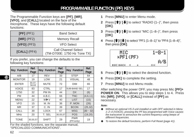
62
13
PROGRAMMABLE FUNCTION (PF) KEYS
1 Press [MNU] to enter Menu mode.
2 Press [ccccc]/ [ddddd] to select “RADIO (1–)”, then press[OK] .
3 Press [ccccc]/ [ddddd] to select “MIC (1–8–)”, then press[OK] .
4 Press [ccccc]/ [ddddd] to select “PF1 (1–8–1)” to “PF4 (1–8–4)”,then press [OK] .
5 Press [ccccc]/ [ddddd] to select the desired function.
6 Press [OK] to complete the setting.
7 Press [MNU] to exit Menu mode.
After switching the power OFF, you may press Mic [PF]+POWER ON. This allows you to skip steps 1 to 4. PressMic [MR] , [VFO] , or [CALL] instead of [PF] asnecessary.
Note: Without an optional VS-3 unit installed or with OFF selected in Menu
1–2–4 (VOICE), pressing the PF key programmed with Voice causesthe transceiver to announce the current frequency using beeps ofdifferent frequencies.
To restore the default functions, perform Full Reset page 41.
]FP[ )1FP( tceleSdnaB
]RM[ )2FP( llaceRyromeM
]OFV[ )3FP( tceleSOFV
]LLAC[ )4FP( tceleSlennahCllaC)XTenoTzH0571:E007D-MT(
For the shaded functions, see the separate manual,“SPECIALIZED COMMUNICATIONS”.
The Programmable Function keys are [PF] , [MR] ,[VFO] , and [CALL] located on the face of themicrophone. These keys have the following defaultfunctions:
If you prefer, you can change the defaults to thefollowing key functions:
noitcnuFyeK .feRegaP noitcnuFyeK .feR
egaP noitcnuFyeK .feRegaP
B/A 71 VER 33 PETS 46ROTINOM 91 WOL 12 LAUSIV 84
RETNE ,73,0336,65 ETUM 27 MID 56
ECIOV 38 LRTC 71 LESDNAB-BUS 710571 23 NIMP 44 XD )6(
MP 44 .C.B.A 66 CNT )11,6,4(UNEM 22 MsV 04 TSIL )51(
OFV 51 NI.M 63 NOM.P )62(RM 73 NI.C 93 NOCB )23,52(
LLAC 93 KCOL 76 GSM )23~03(zHM 02 LES.T 75,55,03 SOP )02,91(
ENOT 75,55,03 TFIHS 92 RWP)ylno1FP(
91
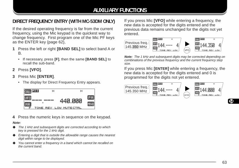
63
14
If you press Mic [VFO] while entering a frequency, thenew data is accepted for the digits entered and theprevious data remains unchanged for the digits not yetentered.
Note: The 1 kHz and subsequent digits may be corrected depending oncombinations of the previous frequency and the current frequency stepsize.
If you press Mic [ENTER] while entering a frequency, thenew data is accepted for the digits entered and 0 isprogrammed for the digits not yet entered.
AUXILIARY FUNCTIONS
Previous freq.:145.350 MHz
Previous freq.:145.350 MHz
DIRECT FREQUENCY ENTRY (WITH MC-53DM ONLY)If the desired operating frequency is far from the currentfrequency, using the Mic keypad is the quickest way tochange frequency. First program one of the Mic PF keysas the ENTER key page 62,
1 Press the left or right [BAND SEL] to select band A orB.
• If necessary, press [F] , then the same [BAND SEL] torecall the sub-band.
2 Press [VFO] .
3 Press Mic [ENTER] .• The display for Direct Frequency Entry appears.
4 Press the numeric keys in sequence on the keypad.Note: The 1 kHz and subsequent digits are corrected according to which
key is pressed for the 1 kHz digit. Entering a digit that is outside the allowable range causes the nearest
digit within range to be displayed. You cannot enter a frequency in a band which cannot be recalled on
the current band.
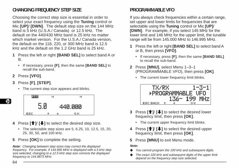
64
14
CHANGING FREQUENCY STEP SIZEChoosing the correct step size is essential in order toselect your exact frequency using the Tuning control orMic [UP] / [DWN] . The default step size on the 144 MHzband is 5 kHz (U.S.A./ Canada) or 12.5 kHz. Thedefault on the 440/430 MHz band is 25 kHz no matterwhich market version. For the U.S.A./ Canada version,the default on the 118, 220, or 300 MHz band is 12.5kHz and the default on the 1.2 GHz band is 25 kHz.
1 Press the left or right [BAND SEL] to select band A orB.
• If necessary, press [F] , then the same [BAND SEL] torecall the sub-band.
2 Press [VFO] .
3 Press [F], [STEP] .• The current step size appears and blinks.
4 Press [ccccc]/ [ddddd] to select the desired step size.• The selectable step sizes are 5, 6.25, 10, 12.5, 15, 20,
25, 30, 50, and 100 kHz.
5 Press [OK] to complete the setting.
Note: Changing between step sizes may correct the displayedfrequency. For example, if 144.995 MHz is displayed with a 5 kHz stepsize selected, changing to a 12.5 kHz step size corrects the displayedfrequency to 144.9875 MHz.
PROGRAMMABLE VFOIf you always check frequencies within a certain range,set upper and lower limits for frequencies that areselectable using the Tuning control or Mic [UP] /[DWN] . For example, if you select 145 MHz for thelower limit and 146 MHz for the upper limit, the tunablerange will be from 145.000 MHz to 146.995 MHz.
1 Press the left or right [BAND SEL] to select band Aor B, then press [VFO] .• If necessary, press [F] , then the same [BAND SEL]
to recall the sub-band.
2 Press [MNU] , select Menu 1–3–1(PROGRAMMABLE VFO), then press [OK] .• The current lower frequency limit blinks.
3 Press [ccccc]/ [ddddd] to select the desired lowerfrequency limit, then press [OK] .
• The current upper frequency limit blinks.
4 Press [ccccc]/ [ddddd] to select the desired upperfrequency limit, then press [OK] .
5 Press [MNU] to exit Menu mode.Note: You cannot program the 100 kHz and subsequent digits. The exact 100 kHz and subsequent digits of the upper limit
depend on the frequency step size selected.
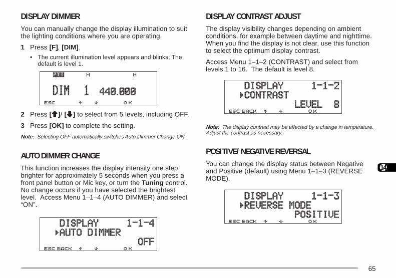
65
14
DISPLAY DIMMERYou can manually change the display illumination to suitthe lighting conditions where you are operating.
1 Press [F], [DIM] .• The current illumination level appears and blinks; The
default is level 1.
2 Press [ccccc]/ [ddddd] to select from 5 levels, including OFF.
3 Press [OK] to complete the setting.
Note: Selecting OFF automatically switches Auto Dimmer Change ON.
AUTO DIMMER CHANGEThis function increases the display intensity one stepbrighter for approximately 5 seconds when you press afront panel button or Mic key, or turn the Tuning control.No change occurs if you have selected the brightestlevel. Access Menu 1–1–4 (AUTO DIMMER) and select“ON”.
DISPLAY CONTRAST ADJUSTThe display visibility changes depending on ambientconditions, for example between daytime and nighttime.When you find the display is not clear, use this functionto select the optimum display contrast.
Access Menu 1–1–2 (CONTRAST) and select fromlevels 1 to 16. The default is level 8.
Note: The display contrast may be affected by a change in temperature.Adjust the contrast as necessary.
POSITIVE/ NEGATIVE REVERSALYou can change the display status between Negativeand Positive (default) using Menu 1–1–3 (REVERSEMODE).
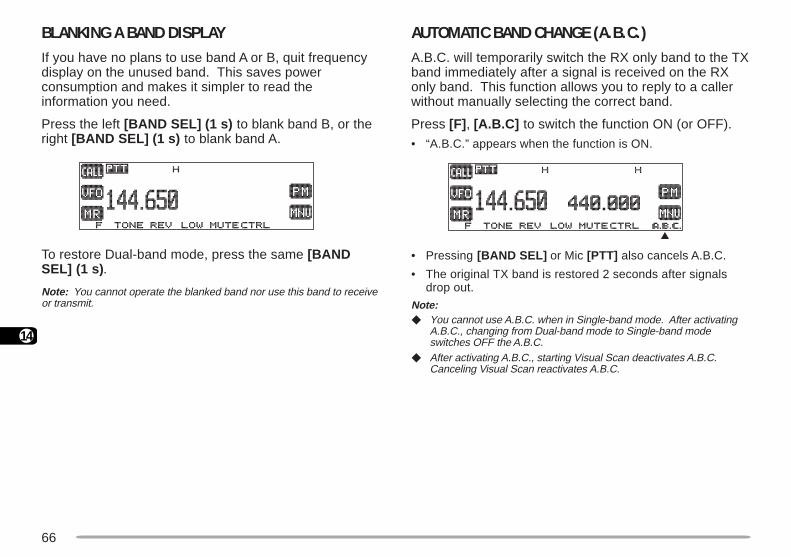
66
14
BLANKING A BAND DISPLAYIf you have no plans to use band A or B, quit frequencydisplay on the unused band. This saves powerconsumption and makes it simpler to read theinformation you need.
Press the left [BAND SEL] (1 s) to blank band B, or theright [BAND SEL] (1 s) to blank band A.
To restore Dual-band mode, press the same [BANDSEL] (1 s).
Note: You cannot operate the blanked band nor use this band to receiveor transmit.
AUTOMATIC BAND CHANGE (A.B.C.)A.B.C. will temporarily switch the RX only band to the TXband immediately after a signal is received on the RXonly band. This function allows you to reply to a callerwithout manually selecting the correct band.
Press [F] , [A.B.C] to switch the function ON (or OFF).
• “A.B.C.” appears when the function is ON.
• Pressing [BAND SEL] or Mic [PTT] also cancels A.B.C.
• The original TX band is restored 2 seconds after signalsdrop out.
Note: You cannot use A.B.C. when in Single-band mode. After activating
A.B.C., changing from Dual-band mode to Single-band modeswitches OFF the A.B.C.
After activating A.B.C., starting Visual Scan deactivates A.B.C.Canceling Visual Scan reactivates A.B.C.
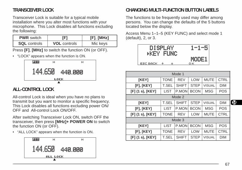
67
14
TRANSCEIVER LOCKTransceiver Lock is suitable for a typical mobileinstallation where you alter most functions with yourmicrophone. This Lock disables all functions excludingthe following:
Press [F] , [MHz] to switch the function ON (or OFF).
• “LOCK” appears when the function is ON.
ALL-CONTROL LOCKAll-control Lock is ideal when you have no plans totransmit but you want to monitor a specific frequency.This Lock disables all functions excluding power ON/OFF and All-control Lock ON/OFF.
After switching Transceiver Lock ON, switch OFF thetransceiver, then press [MHz]+ POWER ON to switchthe function ON (or OFF).• “ALL LOCK” appears when the function is ON.
CHANGING MULTI-FUNCTION BUTTON LABELSThe functions to be frequently used may differ amongpersons. You can change the defaults of the 5 buttonslocated below the display.
Access Menu 1–1–5 (KEY FUNC) and select mode 1(default), 2, or 3.RWP hctiws ]F[ ]F[ , ]zHM[
LQS slortnoc LOV slortnoc syekciM
1edoM
]YEK[ ENOT VER WOL ETUM LRTC
]YEK[,]F[ LES.T TFIHS PETS LAUSIV MID
]YEK[,)s1(]F[ TSIL NOM.P NOCB GSM SOP
2edoM
]YEK[ LES.T TFIHS PETS LAUSIV MID
]YEK[,]F[ TSIL NOM.P NOCB GSM SOP
]YEK[,)s1(]F[ ENOT VER WOL ETUM LRTC
3edoM
]YEK[ TSIL NOM.P NOCB GSM SOP
]YEK[,]F[ ENOT VER WOL ETUM LRTC
]YEK[,)s1(]F[ LES.T TFIHS PETS LAUSIV MID
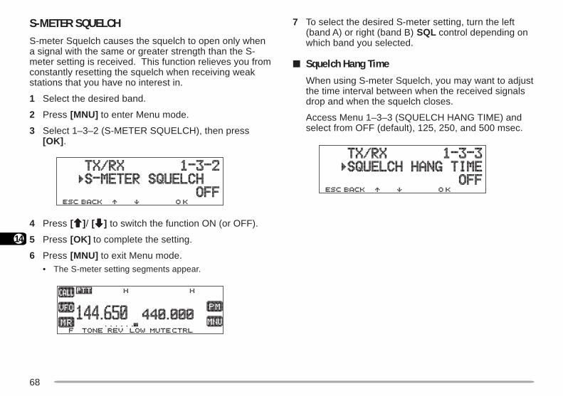
68
14
S-METER SQUELCHS-meter Squelch causes the squelch to open only whena signal with the same or greater strength than the S-meter setting is received. This function relieves you fromconstantly resetting the squelch when receiving weakstations that you have no interest in.
1 Select the desired band.
2 Press [MNU] to enter Menu mode.
3 Select 1–3–2 (S-METER SQUELCH), then press[OK] .
4 Press [ccccc]/ [ddddd] to switch the function ON (or OFF).
5 Press [OK] to complete the setting.
6 Press [MNU] to exit Menu mode.• The S-meter setting segments appear.
7 To select the desired S-meter setting, turn the left(band A) or right (band B) SQL control depending onwhich band you selected.
Squelch Hang Time
When using S-meter Squelch, you may want to adjustthe time interval between when the received signalsdrop and when the squelch closes.
Access Menu 1–3–3 (SQUELCH HANG TIME) andselect from OFF (default), 125, 250, and 500 msec.
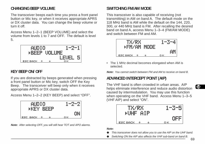
69
14
CHANGING BEEP VOLUMEThe transceiver beeps each time you press a front panelbutton or Mic key, or when it receives appropriate APRSor DX cluster data. You can change the beep volume orturn it off.
Access Menu 1–2–1 (BEEP VOLUME) and select thevolume from levels 1 to 7 and OFF. The default is level5.
KEY BEEP ON/ OFFIf you are distracted by beeps generated when pressinga front panel button or Mic key, switch OFF the KeyBeep. The transceiver will beep only when it receivesappropriate APRS or DX cluster data.
Access Menu 1–2–2 (KEY BEEP) and select “OFF”.
Note: After selecting OFF, you will still hear TOT and APO alarms.
SWITCHING FM/AM MODEThis transceiver is also capable of receiving (nottransmitting) in AM on band A. The default mode on the118 MHz band is AM while the default on the 144, 220,300, or 440 MHz band is FM. After recalling the desiredband on band A, access Menu 1–3–4 (FM/AM MODE)and switch between FM and AM.
• The 1 MHz decimal becomes elongated when AM isselected.
Note: You cannot switch between FM and AM to receive on band B.
ADVANCED INTERCEPT POINT (AIP)The VHF band is often crowded in urban areas. AIPhelps eliminate interference and reduce audio distortioncaused by intermodulation. You may use this functionwhen operating on the VHF band. Access Menu 1–3–5(VHF AIP) and select “ON”.
Note: This transceiver does not allow you to use the AIP on the UHF band. Switching ON the AIP also affects the VHF sub-band on band B.
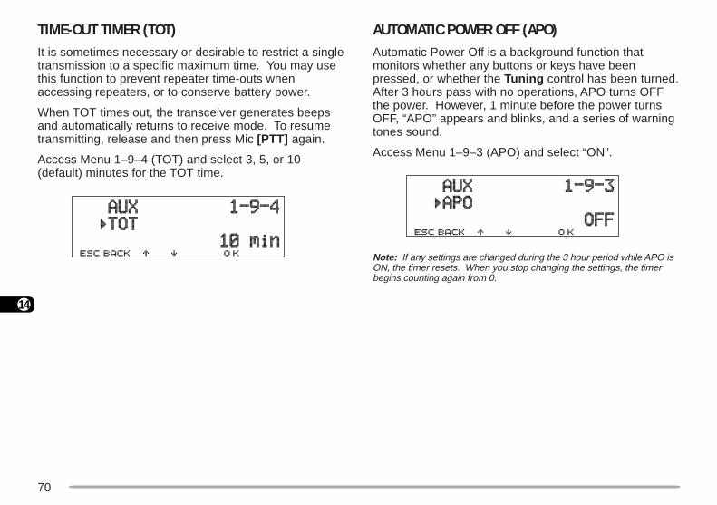
70
14
TIME-OUT TIMER (TOT)It is sometimes necessary or desirable to restrict a singletransmission to a specific maximum time. You may usethis function to prevent repeater time-outs whenaccessing repeaters, or to conserve battery power.
When TOT times out, the transceiver generates beepsand automatically returns to receive mode. To resumetransmitting, release and then press Mic [PTT] again.
Access Menu 1–9–4 (TOT) and select 3, 5, or 10(default) minutes for the TOT time.
AUTOMATIC POWER OFF (APO)Automatic Power Off is a background function thatmonitors whether any buttons or keys have beenpressed, or whether the Tuning control has been turned.After 3 hours pass with no operations, APO turns OFFthe power. However, 1 minute before the power turnsOFF, “APO” appears and blinks, and a series of warningtones sound.
Access Menu 1–9–3 (APO) and select “ON”.
Note: If any settings are changed during the 3 hour period while APO isON, the timer resets. When you stop changing the settings, the timerbegins counting again from 0.
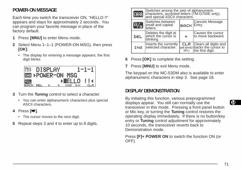
71
14
POWER-ON MESSAGEEach time you switch the transceiver ON, “HELLO !!”appears and stays for approximately 2 seconds. Youcan program your favorite message in place of thefactory default.
1 Press [MNU] to enter Menu mode.
2 Select Menu 1–1–1 (POWER-ON MSG), then press[OK] .
• The display for entering a message appears; the firstdigit blinks.
3 Turn the Tuning control to select a character.
• You can enter alphanumeric characters plus specialASCII characters.
4 Press [aaaaa].• The cursor moves to the next digit.
5 Repeat steps 3 and 4 to enter up to 8 digits.
6 Press [OK] to complete the setting.
7 Press [MNU] to exit Menu mode.
The keypad on the MC-53DM also is available to enteralphanumeric characters in step 3. See page 18.
DISPLAY DEMONSTRATIONBy initiating this function, various preprogrammeddisplays appear. You still can normally use thetransceiver in this mode. Pressing a front panel buttonor Mic key, or turning the Tuning control restores theoperating display immediately. If there is no button/keyentry or Tuning control adjustment for approximately10 seconds, the transceiver reverts back toDemonstration mode.
Press [F]+ POWER ON to switch the function ON (orOFF).
ciremunahplafostesehtgnomasehctiwS,)ylnoE007D-MT(sretteldetnecca,sretcarahc
.sretcarahcIICSAlaicepsdnaneewtebsehctiwSlatipacdnallams
.srettel
egasseMslecnaC.yrtnE
tatigidehtseteleDsirosrucehthcihw
.gniknilb
rosrucehtsesuaC.drawkcabevomot
yltnerrucehtstresnI.retcarahcdetceles DNABtfel(
)LES
dnastigidllasraelCotrosrucehtskcab
.tigidtsrifeht
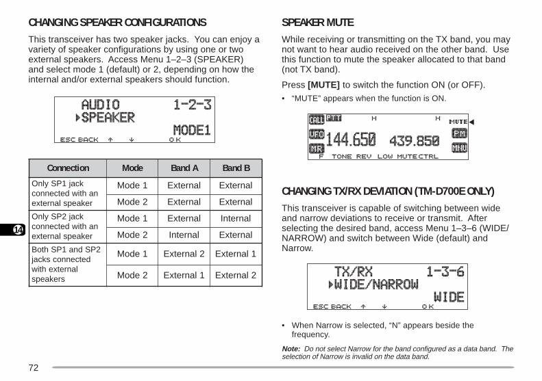
72
14
SPEAKER MUTEWhile receiving or transmitting on the TX band, you maynot want to hear audio received on the other band. Usethis function to mute the speaker allocated to that band(not TX band).
Press [MUTE] to switch the function ON (or OFF).
• “MUTE” appears when the function is ON.
CHANGING TX/RX DEVIATION (TM-D700E ONLY)This transceiver is capable of switching between wideand narrow deviations to receive or transmit. Afterselecting the desired band, access Menu 1–3–6 (WIDE/NARROW) and switch between Wide (default) andNarrow.
• When Narrow is selected, “N” appears beside thefrequency.
Note: Do not select Narrow for the band configured as a data band. Theselection of Narrow is invalid on the data band.
CHANGING SPEAKER CONFIGURATIONSThis transceiver has two speaker jacks. You can enjoy avariety of speaker configurations by using one or twoexternal speakers. Access Menu 1–2–3 (SPEAKER)and select mode 1 (default) or 2, depending on how theinternal and/or external speakers should function.
noitcennoC edoM AdnaB BdnaB
kcaj1PSylnOnahtiwdetcennoc
rekaepslanretxe
1edoM lanretxE lanretxE
2edoM lanretxE lanretxE
kcaj2PSylnOnahtiwdetcennoc
rekaepslanretxe
1edoM lanretxE lanretnI
2edoM lanretnI lanretxE
2PSdna1PShtoBdetcennocskcaj
lanretxehtiwsrekaeps
1edoM 2lanretxE 1lanretxE
2edoM 1lanretxE 2lanretxE
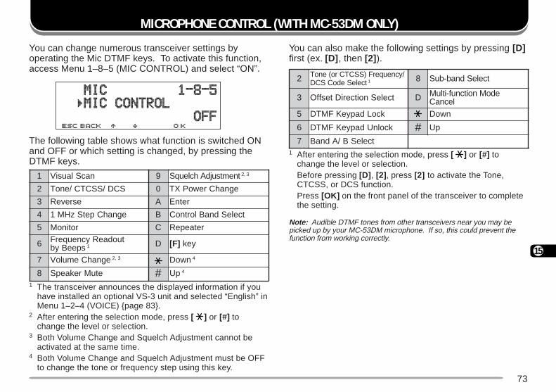
73
15
You can also make the following settings by pressing [D]first (ex. [D] , then [2] ).
1 After entering the selection mode, press [ ] or [#] tochange the level or selection.Before pressing [D] , [2] , press [2] to activate the Tone,CTCSS, or DCS function.Press [OK] on the front panel of the transceiver to completethe setting.
Note: Audible DTMF tones from other transceivers near you may bepicked up by your MC-53DM microphone. If so, this could prevent thefunction from working correctly.
2 /ycneuqerF)SSCTCro(enoTtceleSedoCSCD 1 8 tceleSdnab-buS
3 tceleSnoitceriDtesffO D edoMnoitcnuf-itluMlecnaC
5 kcoLdapyeKFMTD nwoD
6 kcolnUdapyeKFMTD # pU
7 tceleSB/AdnaB
1 nacSlausiV 9 tnemtsujdAhcleuqS 3,2
2 SCD/SSCTC/enoT 0 egnahCrewoPXT
3 esreveR A retnE
4 egnahCpetSzHM1 B tceleSdnaBlortnoC
5 rotinoM C retaepeR
6 tuodaeRycneuqerFspeeByb 1 D ]F[ yek
7 egnahCemuloV 3,2 nwoD 4
8 etuMrekaepS # pU 4
MICROPHONE CONTROL (WITH MC-53DM ONLY)
1 The transceiver announces the displayed information if youhave installed an optional VS-3 unit and selected “English” inMenu 1–2–4 (VOICE) page 83.
2 After entering the selection mode, press [ ] or [#] tochange the level or selection.
3 Both Volume Change and Squelch Adjustment cannot beactivated at the same time.
4 Both Volume Change and Squelch Adjustment must be OFFto change the tone or frequency step using this key.
You can change numerous transceiver settings byoperating the Mic DTMF keys. To activate this function,access Menu 1–8–5 (MIC CONTROL) and select “ON”.
The following table shows what function is switched ONand OFF or which setting is changed, by pressing theDTMF keys.
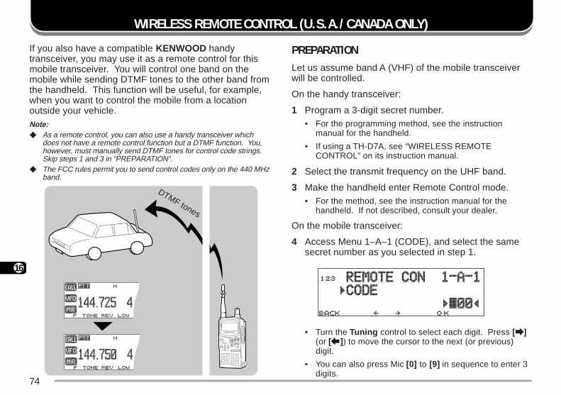
74
16
WIRELESS REMOTE CONTROL (U.S.A./ CANADA ONLY)
If you also have a compatible KENWOOD handytransceiver, you may use it as a remote control for thismobile transceiver. You will control one band on themobile while sending DTMF tones to the other band fromthe handheld. This function will be useful, for example,when you want to control the mobile from a locationoutside your vehicle.Note: As a remote control, you can also use a handy transceiver which
does not have a remote control function but a DTMF function. You,however, must manually send DTMF tones for control code strings.Skip steps 1 and 3 in “PREPARATION”.
The FCC rules permit you to send control codes only on the 440 MHzband.
PREPARATIONLet us assume band A (VHF) of the mobile transceiverwill be controlled.
On the handy transceiver:
1 Program a 3-digit secret number.• For the programming method, see the instruction
manual for the handheld.
• If using a TH-D7A, see “WIRELESS REMOTECONTROL” on its instruction manual.
2 Select the transmit frequency on the UHF band.
3 Make the handheld enter Remote Control mode.• For the method, see the instruction manual for the
handheld. If not described, consult your dealer.
On the mobile transceiver:
4 Access Menu 1–A–1 (CODE), and select the samesecret number as you selected in step 1.
• Turn the Tuning control to select each digit. Press [aaaaa](or [bbbbb]) to move the cursor to the next (or previous)digit.
• You can also press Mic [0] to [9] in sequence to enter 3digits.
DTMF tones
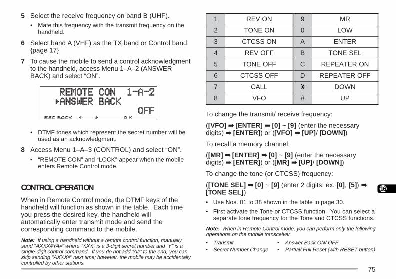
75
16
To change the transmit/ receive frequency:
([VFO] [ENTER] [0] ~ [9] (enter the necessarydigits) [ENTER] ) or ([VFO] [UP] / [DOWN] )
To recall a memory channel:
([MR] [ENTER] [0] ~ [9] (enter the necessarydigits) [ENTER] ) or ([MR] [UP] / [DOWN] )
To change the tone (or CTCSS) frequency:
([TONE SEL] [0] ~ [9] (enter 2 digits; ex. [0] , [5]) [TONE SEL] )
• Use Nos. 01 to 38 shown in the table in page 30.
• First activate the Tone or CTCSS function. You can select aseparate tone frequency for the Tone and CTCSS functions.
Note: When in Remote Control mode, you can perform only the followingoperations on the mobile transceiver.
• Transmit • Answer Back ON/ OFF• Secret Number Change • Partial/ Full Reset (with RESET button)
5 Select the receive frequency on band B (UHF).• Mate this frequency with the transmit frequency on the
handheld.
6 Select band A (VHF) as the TX band or Control bandpage 17.
7 To cause the mobile to send a control acknowledgmentto the handheld, access Menu 1–A–2 (ANSWERBACK) and select “ON”.
• DTMF tones which represent the secret number will beused as an acknowledgment.
8 Access Menu 1–A–3 (CONTROL) and select “ON”.
• “REMOTE CON” and “LOCK” appear when the mobileenters Remote Control mode.
CONTROL OPERATIONWhen in Remote Control mode, the DTMF keys of thehandheld will function as shown in the table. Each timeyou press the desired key, the handheld willautomatically enter transmit mode and send thecorresponding command to the mobile.
Note: If using a handheld without a remote control function, manuallysend “AXXX#YA#” where “XXX” is a 3-digit secret number and “Y” is asingle-digit control command. If you do not add ”A#” to the end, you canskip sending “AXXX#” next time; however, the mobile may be accidentallycontrolled by other stations.
1 NOVER 9 RM
2 NOENOT 0 WOL
3 NOSSCTC A RETNE
4 FFOVER B LESENOT
5 FFOENOT C NORETAEPER
6 FFOSSCTC D FFORETAEPER
7 LLAC NWOD
8 OFV # PU
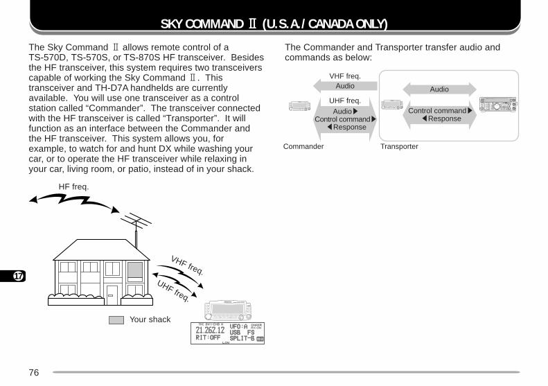
76
17
The Commander and Transporter transfer audio andcommands as below:
SKY COMMAND 22222 (U.S.A./ CANADA ONLY)
The Sky Command 2 allows remote control of aTS-570D, TS-570S, or TS-870S HF transceiver. Besidesthe HF transceiver, this system requires two transceiverscapable of working the Sky Command 2. Thistransceiver and TH-D7A handhelds are currentlyavailable. You will use one transceiver as a controlstation called “Commander”. The transceiver connectedwith the HF transceiver is called “Transporter”. It willfunction as an interface between the Commander andthe HF transceiver. This system allows you, forexample, to watch for and hunt DX while washing yourcar, or to operate the HF transceiver while relaxing inyour car, living room, or patio, instead of in your shack.
HF freq.
VHF freq.UHF freq.
Your shack
PF
ATT PRE-AMP
VOX PROC
SEND
CH1 MIC
CWFSK
LSBUSB
FMAM
AT TUNE
POWERHF TRANSCEIVER TS-570D
PHONES 1CH2
2CH3
3ANT
4REC
5FINE
6NB
7AGC/TONE
8REV
9
CLR
F.LOCK
0 ENT
MIC
PWR
KEY
DELAY MENU 1MHz
SPLIT
M/V
DOWNUP
MR
TF-SET
A=B
SCAN M>VFO M.IN
M.IN
FILTER
CW TUNE
B.C.
N.R.
A/B
CLEAR
RIT
XIT
RIT/XIT
IF SHIFT SQL CH4 6
0 10
2 8
AF RF
LOW
CU
T
HIGHDSP SLOPE
LOW
4 6
0 10
2 8+–
VHF freq.
Commander Transporter
Audio Audio
UHF freq.
Audios Control commands
tResponse
Control commands tResponse
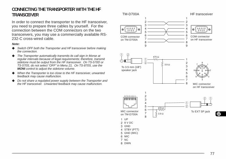
77
17
CONNECTING THE TRANSPORTER WITH THE HFTRANSCEIVERIn order to connect the transporter to the HF transceiver,you need to prepare three cables by yourself. For theconnection between the COM connectors on the twotransceivers, you may use a commercially available RS-232-C cross-wired cable.Note: Switch OFF both the Transporter and HF transceiver before making
the connection. The Transporter automatically transmits its call sign in Morse at
regular intervals because of legal requirements; therefore, transmitsidetone must be output from the HF transceiver. On TS-570D orTS-570S, do not select “OFF” in Menu 21. On TS-870S, use theMONI control to adjust the sidetone volume.
When the Transporter is too close to the HF transceiver, unwantedfeedback may cause malfunction.
Do not share a regulated power supply between the Transporter andthe HF transceiver. Unwanted feedback may cause malfunction.
COM connectoron TM-D700A
To 3.5 mm (1/8")speaker jack
COM connectoron HF transceiver
MIC connectoron HF transceiver
MIC connectoron TM-D700A
HF transceiver
To EXT SP jack
TM-D700A
UP8 V DCGNDSTBY (PTT)GND (MIC)MICNCDWN
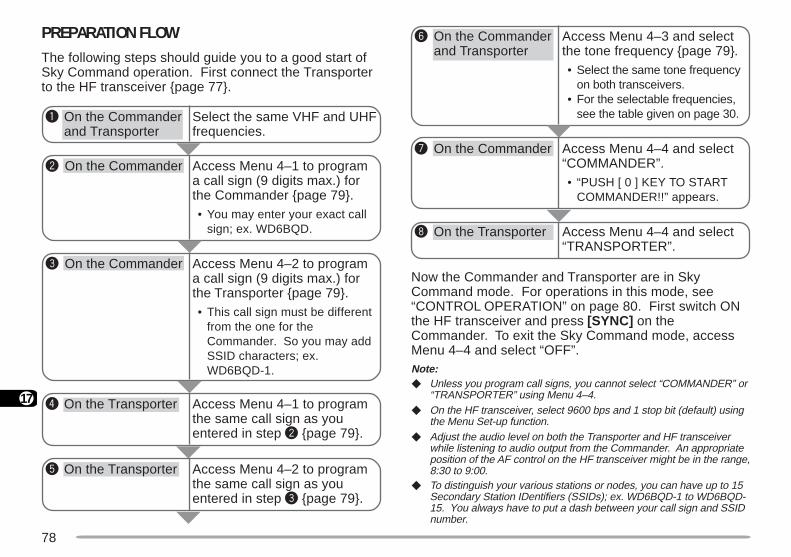
78
17
PREPARATION FLOWThe following steps should guide you to a good start ofSky Command operation. First connect the Transporterto the HF transceiver page 77.
y On the Commanderand Transporter
u On the Commander
i On the Transporter
Access Menu 4–3 and selectthe tone frequency page 79.• Select the same tone frequency
on both transceivers.• For the selectable frequencies,
see the table given on page 30.
Access Menu 4–4 and select“COMMANDER”.• “PUSH [ 0 ] KEY TO START
COMMANDER!!” appears.
Access Menu 4–4 and select“TRANSPORTER”.
Select the same VHF and UHFfrequencies.
Access Menu 4–1 to programa call sign (9 digits max.) forthe Commander page 79.• You may enter your exact call
sign; ex. WD6BQD.
Access Menu 4–1 to programthe same call sign as youentered in step w page 79.
Access Menu 4–2 to programthe same call sign as youentered in step e page 79.
q On the Commanderand Transporter
e On the Commander
w On the Commander
r On the Transporter
t On the Transporter
Access Menu 4–2 to programa call sign (9 digits max.) forthe Transporter page 79.• This call sign must be different
from the one for theCommander. So you may addSSID characters; ex.WD6BQD-1.
Now the Commander and Transporter are in SkyCommand mode. For operations in this mode, see“CONTROL OPERATION” on page 80. First switch ONthe HF transceiver and press [SYNC] on theCommander. To exit the Sky Command mode, accessMenu 4–4 and select “OFF”.Note: Unless you program call signs, you cannot select “COMMANDER” or
“TRANSPORTER” using Menu 4–4. On the HF transceiver, select 9600 bps and 1 stop bit (default) using
the Menu Set-up function. Adjust the audio level on both the Transporter and HF transceiver
while listening to audio output from the Commander. An appropriateposition of the AF control on the HF transceiver might be in the range,8:30 to 9:00.
To distinguish your various stations or nodes, you can have up to 15Secondary Station IDentifiers (SSIDs); ex. WD6BQD-1 to WD6BQD-15. You always have to put a dash between your call sign and SSIDnumber.
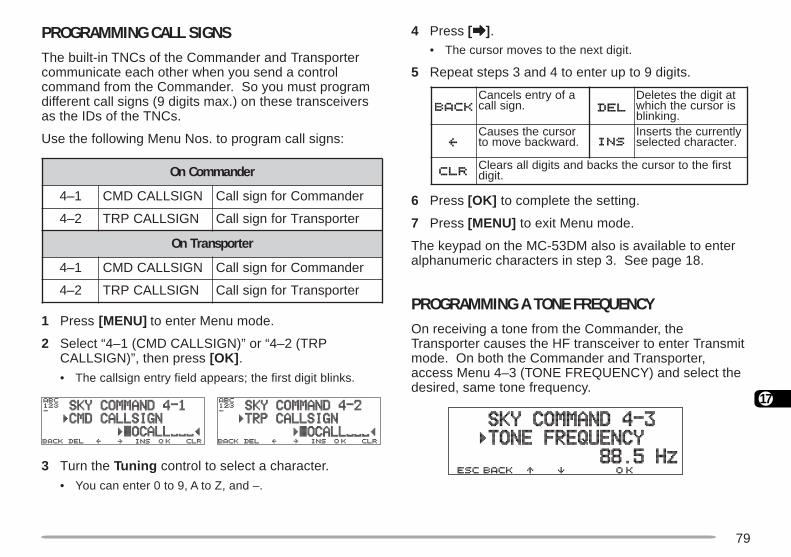
79
17
PROGRAMMING CALL SIGNSThe built-in TNCs of the Commander and Transportercommunicate each other when you send a controlcommand from the Commander. So you must programdifferent call signs (9 digits max.) on these transceiversas the IDs of the TNCs.
Use the following Menu Nos. to program call signs:
1 Press [MENU] to enter Menu mode.
2 Select “4–1 (CMD CALLSIGN)” or “4–2 (TRPCALLSIGN)”, then press [OK] .
• The callsign entry field appears; the first digit blinks.
3 Turn the Tuning control to select a character.
• You can enter 0 to 9, A to Z, and –.
4 Press [aaaaa].• The cursor moves to the next digit.
5 Repeat steps 3 and 4 to enter up to 9 digits.
6 Press [OK] to complete the setting.
7 Press [MENU] to exit Menu mode.
The keypad on the MC-53DM also is available to enteralphanumeric characters in step 3. See page 18.
PROGRAMMING A TONE FREQUENCYOn receiving a tone from the Commander, theTransporter causes the HF transceiver to enter Transmitmode. On both the Commander and Transporter,access Menu 4–3 (TONE FREQUENCY) and select thedesired, same tone frequency.
rednammoCnO
1–4 NGISLLACDMC rednammoCrofngisllaC
2–4 NGISLLACPRT retropsnarTrofngisllaC
retropsnarTnO
1–4 NGISLLACDMC rednammoCrofngisllaC
2–4 NGISLLACPRT retropsnarTrofngisllaC
afoyrtneslecnaC.ngisllac
tatigidehtseteleDsirosrucehthcihw
.gniknilbrosrucehtsesuaC.drawkcabevomot
yltnerrucehtstresnI.retcarahcdetceles
tsrifehtotrosrucehtskcabdnastigidllasraelC.tigid
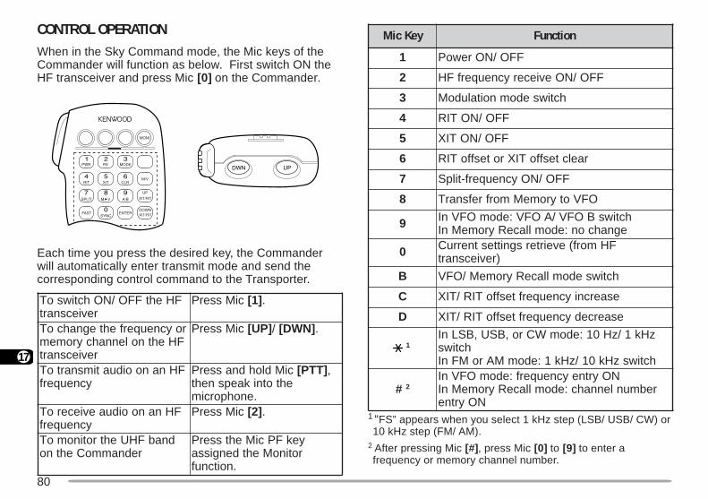
80
17
1 “FS” appears when you select 1 kHz step (LSB/ USB/ CW) or10 kHz step (FM/ AM).
2 After pressing Mic [#] , press Mic [0] to [9] to enter afrequency or memory channel number.
CONTROL OPERATIONWhen in the Sky Command mode, the Mic keys of theCommander will function as below. First switch ON theHF transceiver and press Mic [0] on the Commander.
Each time you press the desired key, the Commanderwill automatically enter transmit mode and send thecorresponding control command to the Transporter.
FHehtFFO/NOhctiwsoTreviecsnart
ciMsserP ]1[ .
roycneuqerfehtegnahcoTFHehtnolennahcyromem
reviecsnart
ciMsserP ]PU[ / ]NWD[ .
FHnanooiduatimsnartoTycneuqerf
ciMdlohdnasserP ]TTP[ ,ehtotnikaepsneht
.enohporcimFHnanooiduaevieceroT
ycneuqerfciMsserP ]2[ .
dnabFHUehtrotinomoTrednammoCehtno
yekFPciMehtsserProtinoMehtdengissa
.noitcnuf
yeKciM noitcnuF
1 FFO/NOrewoP
2 FFO/NOeviecerycneuqerfFH
3 hctiwsedomnoitaludoM
4 FFO/NOTIR
5 FFO/NOTIX
6 raelctesffoTIXrotesffoTIR
7 FFO/NOycneuqerf-tilpS
8 OFVotyromeMmorfrefsnarT
9 hctiwsBOFV/AOFV:edomOFVnIegnahcon:edomllaceRyromeMnI
0 FHmorf(eveirtersgnittestnerruC)reviecsnart
B hctiwsedomllaceRyromeM/OFV
C esaercniycneuqerftesffoTIR/TIX
D esaercedycneuqerftesffoTIR/TIX
1zHk1/zH01:edomWCro,BSU,BSLnI
hctiwshctiwszHk01/zHk1:edomMAroMFnI
# 2NOyrtneycneuqerf:edomOFVnI
rebmunlennahc:edomllaceRyromeMnINOyrtne
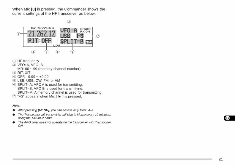
81
17
When Mic [0] is pressed, the Commander shows thecurrent settings of the HF transceiver as below:
q HF frequencyw VFO: A, VFO: B,
MR: 00 ~ 99 (memory channel number)e RIT, XITr OFF, –9.99 ~ +9.99t LSB, USB, CW, FM, or AMy SPLIT–A: VFO A is used for transmitting.
SPLIT–B: VFO B is used for transmitting.SPLIT–M: A memory channel is used for transmitting.
u “FS” appears when Mic [ ] is pressed.
Note: After pressing [MENU] , you can access only Menu 4–4. The Transporter will transmit its call sign in Morse every 10 minutes,
using the 144 MHz band. The APO timer does not operate on the transceiver with Transporter
ON.
q
e yr
u
w
t
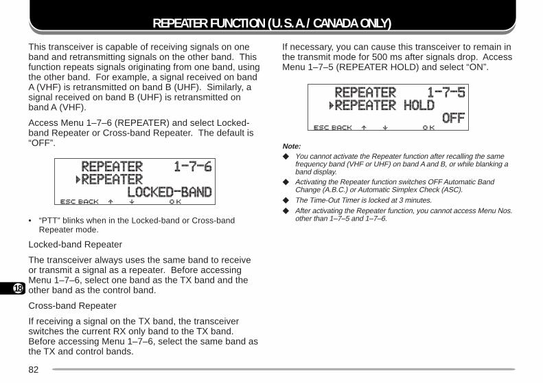
82
18
REPEATER FUNCTION (U.S.A./ CANADA ONLY)
This transceiver is capable of receiving signals on oneband and retransmitting signals on the other band. Thisfunction repeats signals originating from one band, usingthe other band. For example, a signal received on bandA (VHF) is retransmitted on band B (UHF). Similarly, asignal received on band B (UHF) is retransmitted onband A (VHF).
Access Menu 1–7–6 (REPEATER) and select Locked-band Repeater or Cross-band Repeater. The default is“OFF”.
• “PTT” blinks when in the Locked-band or Cross-bandRepeater mode.
Locked-band Repeater
The transceiver always uses the same band to receiveor transmit a signal as a repeater. Before accessingMenu 1–7–6, select one band as the TX band and theother band as the control band.
Cross-band Repeater
If receiving a signal on the TX band, the transceiverswitches the current RX only band to the TX band.Before accessing Menu 1–7–6, select the same band asthe TX and control bands.
If necessary, you can cause this transceiver to remain inthe transmit mode for 500 ms after signals drop. AccessMenu 1–7–5 (REPEATER HOLD) and select “ON”.
Note: You cannot activate the Repeater function after recalling the same
frequency band (VHF or UHF) on band A and B, or while blanking aband display.
Activating the Repeater function switches OFF Automatic BandChange (A.B.C.) or Automatic Simplex Check (ASC).
The Time-Out Timer is locked at 3 minutes. After activating the Repeater function, you cannot access Menu Nos.
other than 1–7–5 and 1–7–6.
Cross-bandRepeater
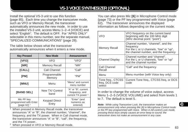
83
19
Install the optional VS-3 unit to use this functionpage 85. Each time you change the transceiver mode,such as VFO or Memory Recall, the transceiverautomatically announces the new mode. In order to usethe installed VS-3 unit, access Menu 1–2–4 (VOICE) andselect “English”. The default is OFF. For “APRS ONLY”selectable in this menu number, see the separate manual,“SPECIALIZED COMMUNICATIONS” page 28.
The table below shows what the transceiverautomatically announces when it enters a new mode.
1 When pressed in Memory Recall mode, the transceiverannounces “A” or “B”, the channel number, “channel”, thefrequency, and the TX power. When in Call channel mode,the transceiver announces “A” or “B”, “call”, the frequency,and the TX power..
2 When pressed in VFO or Memory Recall mode.
In order to change the volume of voice output, accessMenu 1–2–5 (VOICE VOLUME) and select from levels 1to 7. The default is level 5.
Note: While using Transceiver Lock, the transceiver makes anannouncement only when pressing Mic [6] in Microphone Control modeor the PF key programmed with Voice. When in All-control Lock mode,pressing these keys simply causes an error beep to sound; thetransceiver does not make an announcement in any case.
VS-3 VOICE SYNTHESIZER (OPTIONAL)
You can also press Mic [6] in Microphone Control modepage 73 or the PF key programmed with Voice page62. The transceiver announces the displayedinformation as follows depending on the current mode.
desserPyeK edoMweN tnemecnuonnA
]OFV[ OFV ”OFV“
]RM[ llaceRyromeM ”RM“
]LLAC[ lennahCllaC ”llaC“
]MP[ elbammargorPyromeM ”MP“
]UNM[ uneM tnerrucdna”uneM“rebmununem
]LESDNAB[ lortnoC/XTweNdnab
tnerruc,”B“ro”A“dna,ycneuqerfrewopXTtnerruc 1
yekFPciMretnEhtiwdemmargorp
26egap 2
tceriDdapyeKyrtnE
dna(”retnE“sasciremun
)deretne
OFVdnabtnerrucehtnoycneuqerfOFV
tigidzHM001ehthtiwgninnigeb)”tniop“:tnioplamicedzHM(
llaceRyromeM
ehtdna,”lennahc“,rebmunlennahCycneuqerf
,”pu“ro”wol“,slennahcUroLehtroFycneuqerfehtdna,rebmunlennahceht
yalpsiDlennahC.”lennahc“dnarebmunlennahC
”pu“ro”wol“,slennahcUroLehtroFrebmunlennahcehtdna
lennahCllaCllaceR
ycneuqerfehtdna”llaC“
uneM )ylnoyekecioVhtiw(rebmumuneM
SSCTC,.qerfenoTedocSCD,qerf
tceles
SCDro,qerfSSCTC,.qerfenoTtnerruCedoc
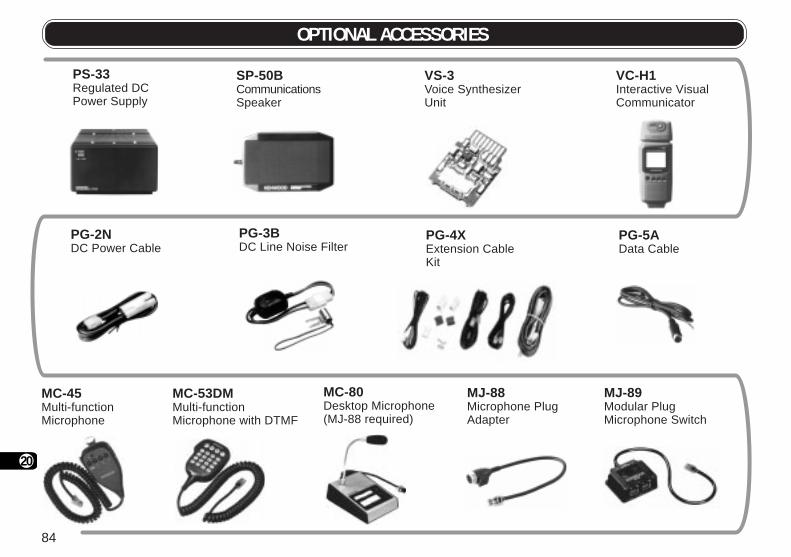
84
20
OPTIONAL ACCESSORIES
MJ-88Microphone PlugAdapter
PG-2NDC Power Cable
VS-3Voice SynthesizerUnit
VC-H1Interactive VisualCommunicator
SP-50BCommunicationsSpeaker
PG-5AData Cable
PG-3BDC Line Noise Filter
MJ-89Modular PlugMicrophone Switch
MC-45Multi-functionMicrophone
MC-53DMMulti-functionMicrophone with DTMF
MC-80Desktop Microphone(MJ-88 required)
PG-4XExtension CableKit
PS-33Regulated DCPower Supply

85
21
INSTALLING THE VS-3 VOICE SYNTHESIZER UNIT
Always switch off the power and unplug the DC power cable first.
1 Remove the 6 screws from the lower cover of themain unit.
2 Hold the VS-3 unit with the component side facingupward, and insert the VS-3 connector into thecorresponding transceiver connector; the componentside must not face downward.
3 Replace the lower cover (6 screws).
INSTALLING THE PG-4X EXTENSION CABLE KITThe PG-4X kit is available to extend the variousconnection cables. For the cable connections, see thenext page. With two sets of PG-4X kits, you can extendthe cables to the maximum length.
The PG-4X kit also includes noise filters, modular plugadapter cushions, and cable clamps. The followingdiagrams illustrate how to install these accessories.
Component side
Approx. 3 cm
Approx. 3 cm
From front panel
Frommicrophone
Noise filter
INSTALLING OPTIONS
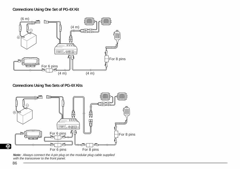
86
21
Connections Using One Set of PG-4X Kit
Connections Using Two Sets of PG-4X Kits
(4 m)(4 m)
(4 m)
(6 m)
For 6 pins
For 8 pins
Note: Always connect the 4-pin plug on the modular plug cable suppliedwith the transceiver to the front panel.
For 6 pins
For 6 pins
For 8 pins
For 8 pins
87
22
MAINTENANCE
GENERAL INFORMATIONThis product has been factory aligned and tested tospecification before shipment. Attempting service oralignment without factory authorization can void theproduct warranty.
SERVICEWhen returning this product to your dealer or servicecenter for repair, pack it in its original box and packingmaterial. Include a full description of the problem(s)experienced. Include your telephone number along withyour name and address in case the service technicianneeds to call you; if available, include also your faxnumber and e-mail address. Don’t return accessoryitems unless you feel they are directly related to theservice problem.
You may return this product for service to the authorizedKENWOOD dealer from whom you purchased it, or anyauthorized KENWOOD service center. Please do notsend subassemblies or printed circuit boards. Send thecomplete product. A copy of the service report will bereturned with the product.
SERVICE NOTEIf you desire to correspond on a technical or operationalproblem, please make your note legible, short, complete,and to the point. Help us help you by providing thefollowing:
• Model and serial number of equipment
• Question or problem you are having
• Other equipment in your station pertaining to the problem
Do not pack the equipment in crushed newspapers for shipment!Extensive damage may result during rough handling or shipping.
Note: Record the date of purchase, serial number and dealer from whom
this product was purchased. For your own information, retain a written record of any maintenance
performed on this product. When claiming warranty service, please include a photocopy of the
bill of sale, or other proof-of-purchase showing the date of sale.
CLEANINGTo clean the case of this product, use a neutral detergent(no strong chemicals) and a damp cloth.
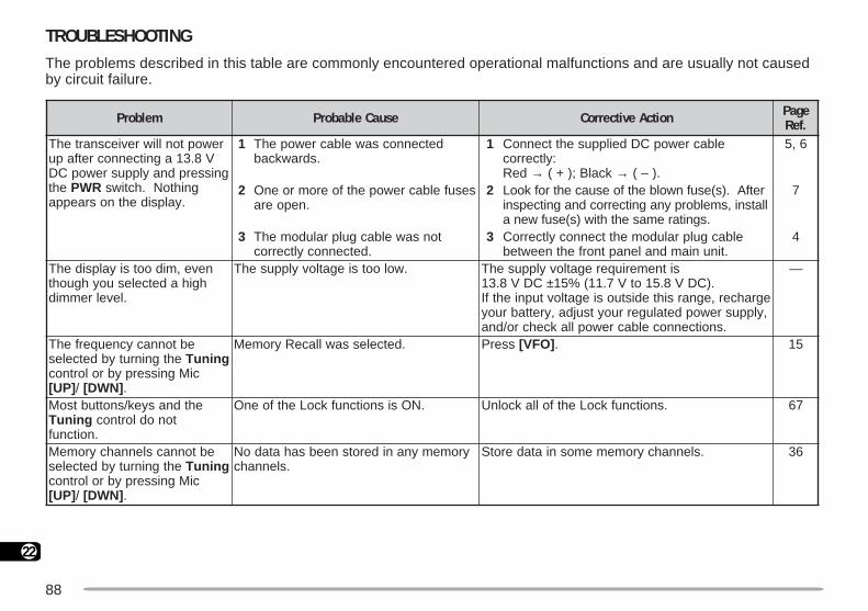
88
22
TROUBLESHOOTINGThe problems described in this table are commonly encountered operational malfunctions and are usually not causedby circuit failure.
melborP esuaCelbaborP noitcAevitcerroC egaP.feR
rewoptonlliwreviecsnartehTV8.31agnitcennocretfapu
gnisserpdnaylppusrewopCDeht RWP gnihtoN.hctiws
.yalpsidehtnosraeppa
1 detcennocsawelbacrewopehT.sdrawkcab
1 elbacrewopCDdeilppusehttcennoC:yltcerroc
deR → kcalB;)+( → .)–(
6,5
2 sesufelbacrewopehtfoeromroenO.nepoera
2 retfA.)s(esufnwolbehtfoesuacehtrofkooLllatsni,smelborpynagnitcerrocdnagnitcepsni
.sgnitaremasehthtiw)s(esufwena
7
3 tonsawelbacgulpraludomehT.detcennocyltcerroc
3 elbacgulpraludomehttcennocyltcerroC.tinuniamdnalenaptnorfehtneewteb
4
neve,midootsiyalpsidehThgihadetcelesuoyhguoht
.levelremmid
.wolootsiegatlovylppusehT sitnemeriuqeregatlovylppusehTCDV8.31 ± .)CDV8.51otV7.11(%51
egrahcer,egnarsihtedistuosiegatlovtupniehtfI,ylppusrewopdetalugerruoytsujda,yrettabruoy
.snoitcennocelbacrewopllakcehcro/dna
—
ebtonnacycneuqerfehTehtgninrutybdetceles gninuT
ciMgnisserpybrolortnoc]PU[ / ]NWD[ .
.detcelessawllaceRyromeM sserP ]OFV[ . 51
ehtdnasyek/snottubtsoMgninuT tonodlortnoc
.noitcnuf
.NOsisnoitcnufkcoLehtfoenO .snoitcnufkcoLehtfollakcolnU 76
ebtonnacslennahcyromeMehtgninrutybdetceles gninuT
ciMgnisserpybrolortnoc]PU[ / ]NWD[ .
yromemynaniderotsneebsahatadoN.slennahc
.slennahcyromememosniataderotS 63

89
22
melborP esuaCelbaborP noitcAevitcerroC egaP.feR
nevetimsnarttonnacuoYciMsserpuoyhguoht ]TTP[ .
1 tonsawgulpenohporcimehTtnorfehtotniyletelpmocdetresni
.rotcennoclenap
1 ehttresnineht,rewopehtFFOhctiwSniskcilcbatgnikcolehtlitnugulpenohporcim
.ecalp
8
2 tahttesffotimsnartadetcelesuoYedistuoycneuqerftimsnartehtsecalp
ycneuqerftimsnartelbawollaeht.egnar
2 sserP ]F[ , ]TFIHS[ ”+“rehtienosyldetaeper.elbisivsi”–“ron
92
3 CNTlanretxenaro(CNTni-tliubehT.gnittimsnartsaw)detcennocfi
3 ciMsserP ]TTP[ dehsinifCNTehtretfa.noissimsnart
—
otsliafrednammoCehTFHehtfosutatsehtyalpsid
.reviecsnart
1 llacmargorpyltcerroctondiduoYdnarednammoCehtnosngis
.retropsnarT
1 ,retropsnarTdnarednammoCehthtobnOehtmargorpot2–4dna1–4uneMssecca
.sngisllactcerroc
97
2 tcerrocehttcelestondiduoYFHehtnosretemarapnoitacinummoc
.reviecsnart
2 1dnaspb0069tceles,reviecsnartFHehtnO.noitcnufputeSuneMehtgnisutibpots
87
3 deepssnoitacinummocdetcelesuoY5–9–1uneMnispb0069nahtrehto
.)TROPMOC(
3 .”spb0069“tcelesot5–9–1uneMsseccA 52
oiduatimsnarttonnacuoY.reviecnartFHehtmorf
enotemasehttcelestondiduoYdnarednammoCehtnoycneuqerf
.retropsnarT
,retropsnarTdnarednammoCehthtobnOenotemasehttcelesot3–4uneMssecca
.ycneuqerf
97
rednammoCehtgnitarepOnatuptuoottisesuacylpmiswollatonseoddnapeebrorre
FHehtlortnocotuoy.reviecsnart
1 ehtneewtebecnatsidegralooTretropsnarTdnarednammoC
atadtcerrocstneverp.snoitacinummoc
1 ecnatsidanihtiwrednammoCehtetarepOawohsotsreviecsnartowtehtswollataht
.gnidaerretem-Selacs-lluf
—
2 tneverpsnoitidnocevawoidardaBgniebmorfsdnammoclortnoc
.dettimsnartyltcerroc
2 sserP ]CNYS[ sutatsehtdaerotyllanoisacco.reviecsnartFHehtfo
08
oiduaraehtonnacuoYFHehtybdeviecer
.reviecsnart
441ehtnoSSCTCehtNOdehctiwsuoY.rednammoCehtfodnabzHM
sserP ]ENOT[ .SSCTCehtFFOhctiwsot 55
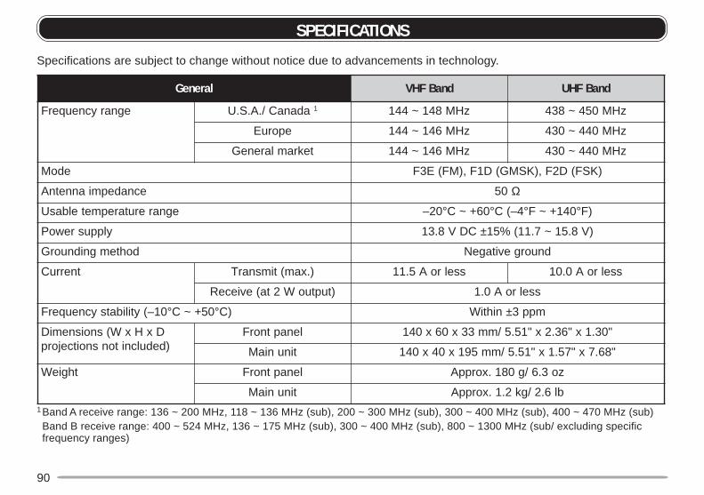
90
SPECIFICATIONS
Specifications are subject to change without notice due to advancements in technology.
1Band A receive range: 136 ~ 200 MHz, 118 ~ 136 MHz (sub), 200 ~ 300 MHz (sub), 300 ~ 400 MHz (sub), 400 ~ 470 MHz (sub)Band B receive range: 400 ~ 524 MHz, 136 ~ 175 MHz (sub), 300 ~ 400 MHz (sub), 800 ~ 1300 MHz (sub/ excluding specificfrequency ranges)
lareneG dnaBFHV dnaBFHU
egnarycneuqerF adanaC/.A.S.U 1 zHM841~441 zHM054~834
eporuE zHM641~441 zHM044~034
tekramlareneG zHM641~441 zHM044~034
edoM )KSF(D2F,)KSMG(D1F,)MF(E3F
ecnadepmiannetnA 05 Ω
egnarerutarepmetelbasU 02– ° 06+~C ° 4–(C ° 041+~F ° )F
ylppusrewoP CDV8.31 ± )V8.51~7.11(%51
dohtemgnidnuorG dnuorgevitageN
tnerruC ).xam(timsnarT sselroA5.11 sselroA0.01
)tuptuoW2ta(evieceR sselroA0.1
01–(ytilibatsycneuqerF ° 05+~C ° )C nihtiW ± mpp3
DxHxW(snoisnemiD)dedulcnitonsnoitcejorp
lenaptnorF "03.1x"63.2x"15.5/mm33x06x041
tinuniaM "86.7x"75.1x"15.5/mm591x04x041
thgieW lenaptnorF zo3.6/g081.xorppA
tinuniaM bl6.2/gk2.1.xorppA
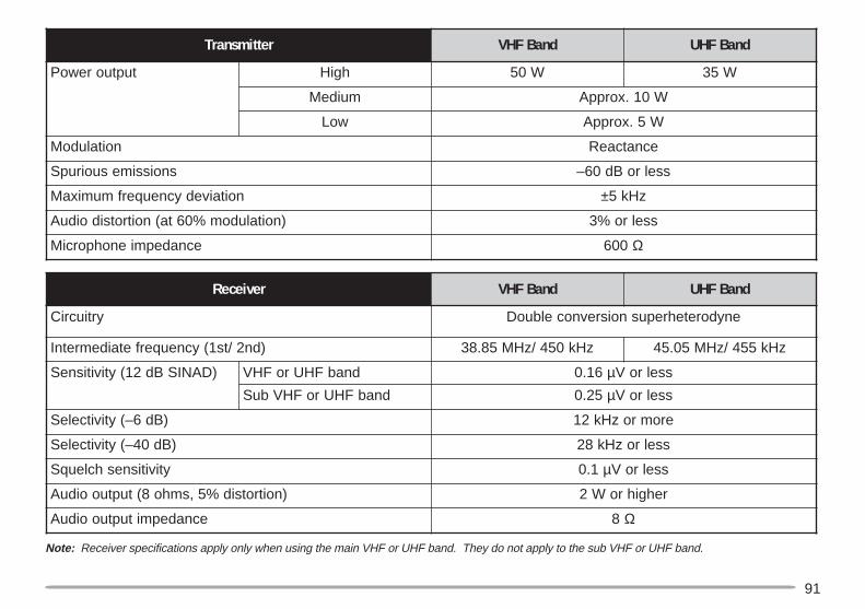
91
Note: Receiver specifications apply only when using the main VHF or UHF band. They do not apply to the sub VHF or UHF band.
rettimsnarT dnaBFHV dnaBFHU
tuptuorewoP hgiH W05 W53
muideM W01.xorppA
woL W5.xorppA
noitaludoM ecnatcaeR
snoissimesuoirupS sselroBd06–
noitaivedycneuqerfmumixaM ± zHk5
)noitaludom%06ta(noitrotsidoiduA sselro%3
ecnadepmienohporciM 006 Ω
revieceR dnaBFHV dnaBFHU
yrtiucriC enydoretehrepusnoisrevnocelbuoD
)dn2/ts1(ycneuqerfetaidemretnI zHk054/zHM58.83 zHk554/zHM50.54
)DANISBd21(ytivitisneS dnabFHUroFHV 61.0 µ sselroV
dnabFHUroFHVbuS 52.0 µ sselroV
)Bd6–(ytivitceleS eromrozHk21
)Bd04–(ytivitceleS sselrozHk82
ytivitisneshcleuqS 1.0 µ sselroV
)noitrotsid%5,smho8(tuptuooiduA rehgihroW2
ecnadepmituptuooiduA 8 Ω
92
INDEXAdvanced Intercept Point(AIP) .................................... 69Automatic Band Change(A. B. C.) .............................. 66Automatic Power Off(APO) .................................. 70Automatic Simplex Check(ASC) .................................. 33Autopatch ............................ 59Channel Display ................... 40Continuous Tone CodedSquelch System (CTCSS)
Freq. ID ............................ 56Using ................................ 55
Digital Code Squelch (DCS)Code ID ............................ 58Using ................................ 57
DisplayBlanking ........................... 66Contrast ........................... 65Demonstration .................. 71Dimmer, Changing............ 65Reversal ........................... 65
Dual Tone Multi-Frequency(DTMF) Functions
Making Calls ..................... 59Pause Duration................. 61Storing Numbers .............. 60Transmitting StoredNumbers .......................... 61TX Speed ......................... 61
MHz ................................. 53Program ........................... 52Time-Operated Resume ... 49VFO ................................. 50Visual ............................... 47
Sky Command 2 ................ 76Speaker
Configurations, changing .. 72Mute ................................. 72
SquelchAdjusting .......................... 20S-meter ............................ 68
Switching FM/AM ................. 69Time-Out Timer (TOT) .......... 70Tone
Activating .......................... 30Freq. ID ............................ 34Selecting .......................... 30
Transmit Output Power ........ 21TX/RX Deviation .................. 72Voice Synthesizer (VS-3) ..... 83Volume
Audio ................................ 19Beep ................................ 69
Wireless Remote Control ..... 74
Frequencies, SelectingMicrophone [UP]/ [DWN] .. 20Tuning Control .................. 20
Frequency Step Size ............ 64Fuses, Replacing ................... 7Keypad Direct Entry
CTCSS Freq. Number ...... 56Frequency ........................ 63Memory ChannelNumber ............................ 37Tone Freq. Number .......... 30
LockAll-control Lock ................. 67Transceiver Lock .............. 67
Memory ChannelsCall Channel, Changing .... 39Call Channel, Recalling .... 39Clearing ............................ 37Locking Out ...................... 51Naming............................. 38Recalling .......................... 37Storing, Odd-split .............. 36Storing, Simplex ............... 36Transfer to VFO ................ 40
MenuAccess ............................. 22Configuration .................... 23
Microphone Control ............. 73
OffsetAutomatic Repeater .......... 31Direction ........................... 29Frequency ........................ 29
Power-ON Message ............ 71Programmable Function(PF) Keys ............................ 62Programmable Memory (PM)
Auto Storing ..................... 45Recalling .......................... 44Resetting .......................... 45Storing .............................. 44
Programmable VFO ............. 64Repeater Access .................. 28Repeater Function
Cross-band....................... 82Locked-band .................... 82
ResetFull (Memory) ................... 41Partial (VFO) .................... 41Programmable Memory(PM) ................................. 45
Reverse Function ................. 33Scan
Call/Memory ..................... 54Call/VFO .......................... 54Carrier-OperatedResume............................ 49Group ............................... 51Memory ............................ 50