Embed Size (px)
Citation preview

8 8 8 .9 5 0 .6 531 CYC L E SAF E.C O M I N F O@CYC L E SAF E.C O M©2009 Cycle-Safe, Inc. *Cycle-Safe® and ProPark® are Federally registered trademarks. Printed on recycled paper.
TM
45˚ ANGLE BRACKETApproximate 3” Depth savings from wall with a 45˚ Angle Bracket. Angle also creates more space for a door to open if racks are placed next to the door.
Additional space saving with use of 45o Angle Bracket
Available in several standard colors to coordinate with existing color schemes.
One bike capacity protects bike frame, and allows for hanging gear U-Lock compatible to secure bike and frame
DIMENSION DRAWING
ORDER INFORMATION:• Wallrack #17502 - (R) red, (BL) blue, (BK) black, (S) silver • Stainless Steel #17503 upon request• Concrete lag shield #17504• Extra lag screw #17505• 45o angle bracket #17513
SPECIFICATIONS:• Heavy duty 3/8” wire frame• Durable polyester powder coat finish• Tamper resistant lag screws included• Optional 45o angle bracket• Custom colors upon request
25.5"
22.5"
14"
NOTE: NEW design conforms to bicycle wheel.
Hardware Included
Hardware kit (part# 17513) includes:2 - 45˚ angle brackets4 - 3/8 - 16 x 1” stainless steel button head cap screws4 - 3/8” stainless steel washers4 - 3/8 - 16 stainless steel weld nuts.
Wall
Wall
110”
107”
48”Minimum
72”Maximum
45˚ Angle Increases Aisle Width
12"
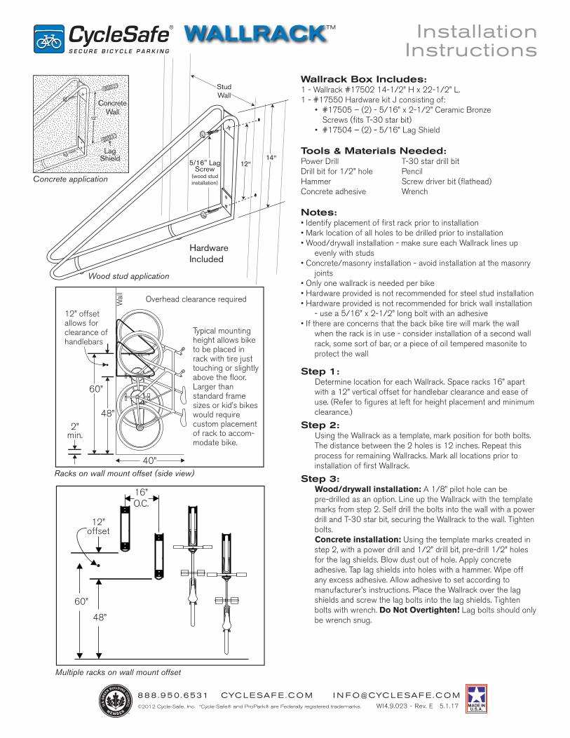
Racks on wall mount offset (side view)
TM
Wood stud application
60”
40”
48”
Typical mounting height allows bike to be placed in rack with tire just touching or slightly above the floor. Larger than standard frame sizes or kid’s bikes would require custom placement of rack to accom-modate bike.
12” offset allows for clearance of handlebars
Wal
l
Wallrack Box Includes:1 - Wallrack #17502 14-1/2” H x 22-1/2” L.1 - #17550 Hardware kit J consisting of: • #17505 – (2) - 5/16” x 2-1/2” Ceramic Bronze
Screws (fits T-30 star bit) • #17504 – (2) - 5/16” Lag Shield
Tools & Materials Needed:Power Drill T-30 star drill bitDrill bit for 1/2” hole PencilHammer Screw driver bit (flathead)Concrete adhesive Wrench
Notes:• Identify placement of first rack prior to installation• Mark location of all holes to be drilled prior to installation• Wood/drywall installation - make sure each Wallrack lines up
evenly with studs• Concrete/masonry installation - avoid installation at the masonry
joints• Only one wallrack is needed per bike• Hardware provided is not recommended for steel stud installation• Hardware provided is not recommended for brick wall installation
- use a 5/16” x 2-1/2” long bolt with an adhesive• If there are concerns that the back bike tire will mark the wall
when the rack is in use - consider installation of a second wall rack, some sort of bar, or a piece of oil tempered masonite to protect the wall
Step 1: Determine location for each Wallrack. Space racks 16” apart
with a 12” vertical offset for handlebar clearance and ease of use. (Refer to figures at left for height placement and minimum clearance.)
Step 2: Using the Wallrack as a template, mark position for both bolts.
The distance between the 2 holes is 12 inches. Repeat this process for remaining Wallracks. Mark all locations prior to installation of first Wallrack.
Step 3: Wood/drywall installation: A 1/8” pilot hole can be
pre-drilled as an option. Line up the Wallrack with the template marks from step 2. Self drill the bolts into the wall with a power drill and T-30 star bit, securing the Wallrack to the wall. Tighten bolts.
Concrete installation: Using the template marks created in step 2, with a power drill and 1/2” drill bit, pre-drill 1/2” holes for the lag shields. Blow dust out of hole. Apply concrete adhesive. Tap lag shields into holes with a hammer. Wipe off any excess adhesive. Allow adhesive to set according to manufacturer’s instructions. Place the Wallrack over the lag shields and screw the lag bolts into the lag shields. Tighten bolts with wrench. Do Not Overtighten! Lag bolts should only be wrench snug.
8 8 8 .9 5 0 .6 531 CYC L E SAF E.C O M I N F O@CYC L E SAF E.C O M©2012 Cycle-Safe, Inc. *Cycle-Safe® and ProPark® are Federally registered trademarks.
Installation Instructions
ConcreteWall
Concrete application
Lag Shield
WI4.9.023 - Rev. E 5.1.17
HardwareIncluded
StudWall
12"5/16" Lag Screw
(wood stud installation)
14"
2”min.
Overhead clearance required
Multiple racks on wall mount offset
12”offset
60”
48”
16”O.C.
2.25"Inside
Dimension
3"Outside
Dimension
8 8 8 .9 5 0 .6 531 CYC L E SAF E.C O M I N F O@CYC L E SAF E.C O M©2009 Cycle-Safe, Inc. *Cycle-Safe® and ProPark® are Federally registered trademarks. Printed on recycled paper.
TM
45˚ ANGLE BRACKETApproximate 3” Depth savings from wall with a 45˚ Angle Bracket. Angle also creates more space for a door to open if racks are placed next to the door.
Additional space saving with use of 45o Angle Bracket
Available in several standard colors to coordinate with existing color schemes.
One bike capacity protects bike frame, and allows for hanging gear U-Lock compatible to secure bike and frame
DIMENSION DRAWING
ORDER INFORMATION:• Wallrack #17502 - (R) red, (BL) blue, (BK) black, (S) silver • Stainless Steel #17503 upon request• Concrete lag shield #17504• Extra lag screw #17505• 45o angle bracket #17513
SPECIFICATIONS:• Heavy duty 3/8” wire frame• Durable polyester powder coat finish• Tamper resistant lag screws included• Optional 45o angle bracket• Custom colors upon request
25.5"
22.5"
14"
NOTE: NEW design conforms to bicycle wheel.
Hardware Included
Hardware kit (part# 17513) includes:2 - 45˚ angle brackets4 - 3/8 - 16 x 1” stainless steel button head cap screws4 - 3/8” stainless steel washers4 - 3/8 - 16 stainless steel weld nuts.
Wall
Wall
110”
107”
48”Minimum
72”Maximum
45˚ Angle Increases Aisle Width
12"
Racks on wall mount offset (side view)
TM
Wood stud application
60”
40”
48”
Typical mounting height allows bike to be placed in rack with tire just touching or slightly above the floor. Larger than standard frame sizes or kid’s bikes would require custom placement of rack to accom-modate bike.
12” offset allows for clearance of handlebars
Wal
l
Wallrack Box Includes:1 - Wallrack #17502 14-1/2” H x 22-1/2” L.1 - #17550 Hardware kit J consisting of: • #17505 – (2) - 5/16” x 2-1/2” Ceramic Bronze
Screws (fits T-30 star bit) • #17504 – (2) - 5/16” Lag Shield
Tools & Materials Needed:Power Drill T-30 star drill bitDrill bit for 1/2” hole PencilHammer Screw driver bit (flathead)Concrete adhesive Wrench
Notes:• Identify placement of first rack prior to installation• Mark location of all holes to be drilled prior to installation• Wood/drywall installation - make sure each Wallrack lines up
evenly with studs• Concrete/masonry installation - avoid installation at the masonry
joints• Only one wallrack is needed per bike• Hardware provided is not recommended for steel stud installation• Hardware provided is not recommended for brick wall installation
- use a 5/16” x 2-1/2” long bolt with an adhesive• If there are concerns that the back bike tire will mark the wall
when the rack is in use - consider installation of a second wall rack, some sort of bar, or a piece of oil tempered masonite to protect the wall
Step 1: Determine location for each Wallrack. Space racks 16” apart
with a 12” vertical offset for handlebar clearance and ease of use. (Refer to figures at left for height placement and minimum clearance.)
Step 2: Using the Wallrack as a template, mark position for both bolts.
The distance between the 2 holes is 12 inches. Repeat this process for remaining Wallracks. Mark all locations prior to installation of first Wallrack.
Step 3: Wood/drywall installation: A 1/8” pilot hole can be
pre-drilled as an option. Line up the Wallrack with the template marks from step 2. Self drill the bolts into the wall with a power drill and T-30 star bit, securing the Wallrack to the wall. Tighten bolts.
Concrete installation: Using the template marks created in step 2, with a power drill and 1/2” drill bit, pre-drill 1/2” holes for the lag shields. Blow dust out of hole. Apply concrete adhesive. Tap lag shields into holes with a hammer. Wipe off any excess adhesive. Allow adhesive to set according to manufacturer’s instructions. Place the Wallrack over the lag shields and screw the lag bolts into the lag shields. Tighten bolts with wrench. Do Not Overtighten! Lag bolts should only be wrench snug.
8 8 8 .9 5 0 .6 531 CYC L E SAF E.C O M I N F O@CYC L E SAF E.C O M©2012 Cycle-Safe, Inc. *Cycle-Safe® and ProPark® are Federally registered trademarks.
Installation Instructions
ConcreteWall
Concrete application
Lag Shield
WI4.9.023 - Rev. E 5.1.17
HardwareIncluded
StudWall
12"5/16" Lag Screw
(wood stud installation)
14"
2”min.
Overhead clearance required
Multiple racks on wall mount offset
12”offset
60”
48”
16”O.C.
2.25"Inside
Dimension
3"Outside
Dimension