Embed Size (px)
Citation preview

1
TM
Instruction ManualDirect Drive & 5:1 Gear Reduction Under Tailgate Spreaders
UNDER TAILGATE SPREADER WARRANTY
This warranty replaces all previous warranties and no employee of this company is authorized to extend any additional warran-ties, or agreements, or implications not explicitly covered herein. Buyers Products Company warrants all parts of the product to be free from defects in material and workmanship for a period of (1) one year from the date of original installation. Parts must be properly installed and used under normal conditions. Normal wear is excluded.
Any part which has been altered, including modification, misuse, accident, or lack of maintenance will not be considered under this warranty. Hydraulic units are not to be disassembled without the express written permission from Buyers Products Company. The sole responsibility of Buyers Products Company under this warranty is limited to repairing or replacing any part(s) which are returned, prepaid, 30 days after such defect is discovered, and returned part(s) are found to be defective by Buyers Products Company.
Authorization from Buyers Products Company must be obtained before returning any part. The following information must accom-pany defective parts returned to Buyers Products Company: RMA#, spreader model, serial number, date installed, and distributor from whom it was purchased. Buyers Products Company shall not be liable for damage arising out of failure of any unit to operate prop-erly, or failure, or delay in work, or for any consequential damages. No charges for transportation or labor performed on any part will be allowed under this warranty.
Table of ContentsWarranty Information ............................................... 1Spreader Installation Instructions ........................ 1,2Spreader Installation Drawing ................................. 2Spinner Assembly Instructions ................................ 3Spinner Assembly Drawing ...................................3,4Hydraulics Installation ............................................. 4Operating Instructions ...........................................5,6Recommended Maintenance .................................... 6Parts list: Spreader Assembly .................................. 7Spreader Parts Drawing ........................................... 7Parts List: Hardware Box ......................................... 8Spinner Components Drawing ................................. 8Auger Replacement Kits ........................................... 8
Installation Instructions
NOTE: The left and right end plates may, on occasion, get bent through improper handling during shipment or storage. If this should hap-pen, square and true the left and right end plates before installation.1. Aligning the spreader:A. Position the spreader with the truck such that the auger drive is located on the right side of the truck (passenger side).B. Lift the spreader up and under the dump body tailgate, positioning the spreader forward as close as possible to the dump body. The tailgate of the dump body should lay down horizontally over the spreader.C. Support the spreader solidly and securely when positioning for mounting.2. Attach mounting brackets (See hardware installation drawing on page 2.)A. Attach a quick detach plate, (Item 1) to both sides of the spreader frame using hinge pins (Item 2) and a hairpin cotter pins (Item 5).B. Position the (2) quick detach plates over the dump body rub rails and flush with rear edge of dump body.C. Weld the (2) quick detach plates to the dump body rub rails. Weld the plates continuously around (3) sides of each plate. Do not weld along the edge of the plates next to the attachment pin.
—continued inside
9049 Tyler Blvd. • Mentor, Ohio 44060Phone (440) 974-8888 • Fax (440) 974-0165Toll-Free Fax 800-841-8003 • saltdogg.com
NOTE: This manual applies to spreaders with a top screen.

2
TM
D. Align the pin brace (Item 4) on the dump body using the iron brace (Item 3) for exact positioning. For proper fit, hanger iron brace may require some minor bending.E. Weld the (2) pin braces (Item 4) to the dump body sides, all around.F. Attach the iron braces (Item 3) to the pin braces on the sides of the dump body and the sides of the spreader using (2) hairpin cotter pins (Item 5).
G. If there is a gap between the spreader and the dump body, weld or bolt a steel strip to the forward edge of the spreader to cover the gap. H. If you have purchased the tailgate side shields (purchased separately as P/N 924F0106PR or 924F0106SSPR, Stainless), bolt or weld them to the inside of the tailgate to prevent material spillage at the ends of the spreader.
1
2
3
4
5
DUMP BODY
SPREADER FRAME
Mounting Hardware Installation Drawing
Bill of Materials ITEM QTY. DESCRIPTION CARBON STAINLESS
1 2 Quick Detach Plate 924F0102 30095262 2 Hinge Pin 924F0103 30111393 2 Hanger Iron Brace 924F0101 30111374 2 Pin Brace 9240021B 30002105 6 Hair Pin Cotter 5/32" — —
NOTE: Lockout hardware is not shown

3
TM
3. Spinner assembly installation: (See installation drawings on pages 3 and 4.)
A. Attach the spinner shield (Item 2) to the spinner frame (Item 1) using (2) 5/16-18 x 1-1/4 cap screws, 5/16 flat washers and (2) 5/16-18 hex flange nuts.
B. Attach the spinner disk sub assembly to the hydraulic motor on the spinner frame and tighten the set screw in the disk collar.
Note: Be sure to lubricate the hydraulic motor shaft generously with Never Seez lubricant before assembling.
C. Attach the spinner frame assembly to the lower tray of the spreader with the hinge rod and attach (2) hairpin cotter pins.
D. The leveling mechanism may now be mounted. Park truck on flat, level surface. With spinner assembly in level position, carefully measure “L” and “D” distances. Use any of 3 available holes in height adjustment bracket. Locate bar or spinner lug such that ½” hole will position with D1=D and L1=L. Modify angle if necessary.
E. Secure bar or spinner lug to the truck frame.
F. Attach parallel linkage rods to heights adjustment bracket and angle. Secure them using ½” washers and hair pins.
G. Clamp parallel linkage rods together. To verify leveling action, slowly raise the dump. Be sure that spinner motor assembly and linkages do not have any interference with truck body and it does not have contact with the road. After checking weld parallel linkage bars together.
H. Keeping the spinner assembly level, remove the set screw from the clamp collar and secure the spinner frame in place using the spinner assembly lock.
Truck FrameHinge Rod
SpinnerFrame
Spinner Lug or Bar
Spreader
Dump BodyHinge
BarParallelLinkageHole
L1 L
Parallel Linkage, Spinner Frame & Bar Installation Drawings

4
TM
3
2
1
8
5
6
7
4
Hydraulic Installation Instructions
A. During assembly take precautions to keep all hydraulic components as clean as possible.B. Allow enough hose length to prevent kinking and stretching of the hoses and to permit raising the dump body. Support long hoses with wire ties or clamps.C. Protect hoses from wear caused by sliding and/or vibration.D. For proper rotation of auger and spinner motors, hoses may be reversed.Note: Use of a pipe joint sealant compatible with hydraulic oil is recommended for all screw fittings.E. Use swivel type hose ends to connect hoses to flow valve. Damage to valve body may occur if the fittings in flow valve are over tightenedF. To achieve an additional positive shutoff of the auger motor, the inlet flow must pass through the bulkhead fitting (preinstalled on the bottom tray), through latch bracket, through the quick disconnect fitting assembly (preinstalled on the side plate) then to the motor.G. Buyers Products recommends a minimum flow rate of 9 GPM @ 1000 rpm to operate our spreaders.
Valve 1/2" Quick Disconnects
Side Plate Mounted 1/2" Quick Disconnects
3/4" (1)Wire Hose
3/4" (1) Wire Hose
1/2" (1) Wire Hose
1/2" (1) Wire Hose
1/2" (1) Wire Hose
Auger MotorCW Rotation
Spinner MotorCCW Rotation
3/4" QuickDisconnects
3/4" (2) Wire Hose
1-1/4" SpiralSuctionHose
3/4" (2) Wire Hose
1/2" (1) Wire Hose
Tank
Pump
3
1 T
A
P
S
Recommended Parts (not included)
Hydraulic Flow Diagram
Parallel Linkage, Spinner Frame & Bar Installation Drawings (cont.)
Bill of Materials ITEM QTY. DESCRIPTION CARBON STAINLESS
1 1 Spinner Frame Assy. 3020184 30184162 1 Spinner Shield 924F0015 30066593 1 Spinner Disk Assy. 3001472A 3001472A4 2 Linkage Rods, Welded 924F0012 924F0012
ITEM QTY. DESCRIPTION CARBON STAINLESS
5 1 Hinge Rod 924F0018 30066466 1 Spinner Lug 924F0013 30066457 1 Bar 924F0014 924F00148 1 Height Adjustment Bracket 3020185 3017175
ITEM PART NO. QTY DESCRIPTION
1 HV715 1 Dual Flow Regulator Valve2 HVC1 1 Dual Flow Regulator Console3 SMR15 1 15 Gallon Reservoir

5
TM
Auger Quick Disconnect Installation
Operating Instructions
1. Pre-start up.A. Use high grade non foaming hydraulic oil to fill reservoir about 3/4 full.B. Position valve on/off lever to off.C. Move auger and spinner knobs on the valve to the open position.D. Engage PTO and circulate hydraulic oil for sev-eral minutes to warm up.E. Move valve on/off lever to on.F. Inspect hydraulic system for leaks.G. Check auger and spinner to see if they are work-ing properly.H. Refill reservoir to 3/4 full.I. Hydraulic system should now be ready for use.2. Initial use of spreaderA. Shut off spinner and auger knobs and position the on/off lever to on. Engage the PTO and allow the hydraulic system to warm up.B. Open the cover plate and secure vertically with locking brackets.C. Open dump body tailgate as wide as possible from bottom without bearing against cover plate. Set stop chains.D. Position spinner assembly to the far left (drivers side), tighten clamp. Determine placement of mate-rial at various spinner and auger speeds by spread-ing a small amount of material (Far left position used to spread (3) three or (4) four lane highway from right lane).E. Position spinner assembly to the far right (pas-senger side), tighten clamp. Determine placement of material at various spinner and auger speeds by spreading a small amount of material (Far right position used to spread (4) four lane highway from left lane).F. Changing auger and spinner speeds on the valve and placing spinner at various positions from left to right will produce various spread patterns.
CAUTIONA. Be sure everyone is standing clear.B. Be alert for anything that may require shutting down the system.C. Before working in or around spreader equip-ment, be sure all hydraulic controls are moved to off position.
Attach Inlet Flow Here
Hose must passthrough bracket
Flow toMotor

6
TM
3. Using the Auger Lock-out SystemA. Shut off spinner and auger then position the main hydraulics on/off lever to off. Turn off truck.B. Verify hydraulic system is shut off then discon-nect the quick disconnect fitting on the side plate of the spreader.C. The lower tray may now be opened for servicing.D. After servicing, close and lock the tray in op-erating position then reroute the hydraulic hose through the latch bracket and reconnect the quick disconnect coupler.E. Verify that all hydraulic components are still in operational condition, turn the main hydrau-lics back on and test the function of the unit. If any issues are noticed turn off spreader and main hydraulics then inspect and/or service the entire spreader and/or hydraulic system.
Recommended MaintenanceA. Warm up hydraulic system before using.B. Keep the reservoir 3/4 full with high grade non-foaming hydraulic oil.C. Use precautions to keep contaminants from get-ting in reservoir when filling.D. Quick connects are a prime source of contamination. 1. Clean quick connects before connecting or disconnecting them. 2. Protect quick connects from contaminates.E. Lubricate all bearings with suitable type grease on a regular basis. More frequent lubrication is recommended during periods of heavy use.F. Lubricate the spinner hinge rod periodically.G. Maintain the proper lubrication level in all gear-boxes with SAE 90 gear lubricant.H. When not in use, keep the spreader tray empty to prevent freezing of material around auger in extremely cold weather.I. To extend the life of your spreader: 1. Hose down and clean after each use. 2. Repaint and/or oil after each season.
CAUTIONPosition the valve on/off control lever in the off posi-tion when the spreader is not in use or is removed. In the event the valve on/off control lever is left in the on position, a heat problem may occur as the pump contin-ues to pump oil to the hydraulic valve. This could cause a hose to burst spraying hot oil.
DANGERBefore working in or around the auger area, all power to the spreader must be turned off. Disengage the PTO, shut off the engine and follow the lock out instructions. After servicing is complete, reverse the process to restore the spreader function. NEVER PUT ANY PART OF YOUR BODY INSIDE THE AUGER AREA OF SPREADER.
4. MiscellaneousA. Valve setting changes may be made with truck in motion.B. By moving on/off lever to the off position, spin-ner and auger may be stopped at the same time without changing their valve settings.C. Close cover plate flat over spreader trough and lock in place for normal use of dump truck. Tailgate may be opened from top or bottom.D. When truck is used for extensive hauling the spinner assembly should be removed.E. If auger clogs, shut off spinner, open auger knob valve and increase the engine speed. With the engine at a higher speed, move the valve lever from the on to the off positions rapidly; repeat as needed. This action may unclog the auger. If this action fails to free the auger, manual unclogging will be required.
HYDRAULICS SHOWN DISCONNECTED (AUGER POWER OFF) MAIN POWER
MUST ALSO BE SWITCHED OFF BEFORE TRAY AND LID MAY BE
OPENED FOR SERVICE
HYDRAULICS SHOWN CONNECTED (AUGER POWER ON) TRAY AND LID
MUST REMAIN IN OPERATIONAL POSITIONS
7
TM
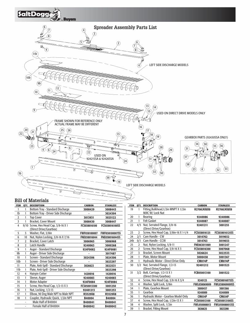
USED ON92421SSA & 92426SSA
LEFT SIDE DISCHARGE MODELS
LEFT SIDE DISCHARGE MODELS
GEARBOX PARTS (92430SSA ONLY)
USED ON DIRECT DRIVE MODELS ONLY
FRAME SHOWN FOR REFERENCE ONLY ACTUAL FRAME MAY BE DIFFERENT
1
1b
2
9b
9
10b
11b
10 1112
13 1415
1617
1819
202122
23
24
24
25 26
664
1939
2829
31
30
32
33
34
5
67
8
4
678
4
3635
3332
34
4
31
37
23
30
3113
38
22
Spreader Assembly Parts List
ITEM QTY. DESCRIPTION CARBON STAINLESS
1 1 Bottom Tray - Standard Discharge 3008429 30084431b 1 Bottom Tray - Driver Side Discharge - 30243042 1 Top Cover 3013931 30251223 1 Bracket, Cover Mount 3008430 30084474 9/10 Screw, Hex Head Cap, 3/8-16 X 1
(Direct Drive/Gearbox)FCS038016100 FCS038016100SS
5 3 Washer, Flat, 3/8in FWF038100007 FWF038100007SS6 10 Nut, Nylon Locking, 3/8-16 X 7/16 FNE038016044 FNE038016044SS7 2 Bracket, Cover Latch 3006965 30069688 2 Latch Handle 9240063 30002689 1 Auger - Standard Discharge 924F0082 924F0081
9b 1 Auger - Driver Side Discharge - 301748710 1 Screen - Standard Discharge 3024306 3024306
10b 1 Screen - Driver Side Discharge - 302329711 1 Plate, Anti-Spill - Standard Discharge 3026623 302253111b 1 Plate, Anti-Spill - Driver Side Discharge - 302329812 4 Hairpin Cotter 1420016 142001613 1 Sleeve, Auger 9240083 924008314 1 Motor Adapter 924F0084 924F008415 1 Screw, Hex Head Cap, 1/2-13 X 3 FCS050013300 300125016 1 Nut, Locking, 1/2-13 92401213 300125317 1 Elbow, 90 Deg Male NPT to Male NPT H3529X8 H3529X818 1 Coupler, Hydraulic Quick, 1/2in NPT B40004 B40004
- Male Half of B40004 B400041 B400041- Female Half of B40004 B400042 B400042
Bill of MaterialsITEM QTY. DESCRIPTION CARBON STAINLESS
19 1 Fitting,Bulkhead,1/2in MNPT X 1/2in MJIC W/ Lock Nut
H2706LNX8X8 H2706LNX8X8
20 1 Bearing 9240086 924008621 1 Felt Gasket 9240087 924008722 4/5 Nut, Serrated Flange, 3/8-16
(Direct Drive/Gearbox)92401211 3001255
23 2 Screw, Hex Head Cap, 3/8in-16 X 1-1/4 FCS038016125 FCS038016125SS24 2/1 Cam Handle - CW 3014762 3019032
24b 0/1 Cam Handle - CCW 3014763 301903325 2 Nut, Nylon Locking, 5/8-11 FNE063011069 300124726 2 Screw, Hex Head Cap, 3/8-16 X 3 FCS038016300 300706827 3 Bracket, Screen Mount 3026624 302253328 1 Plate, Motor Mount 3000458 300136729 1 Hydraulic Motor - Direct Drive Only CM074P CM074P30 3/2 Nut, Serrated Flange, 1/2-13
(Direct Drive/Gearbox)92401212 3001523
31 3/2 Bolt, Carriage, 1/2-13 X 1 (Direct Drive/Gearbox)
FCB050013100 3001522
32 4 Screw, Hex Head Cap, 3/8-16 X 3/4 9240125 FCS038016075SS33 4 Washer, Split Lock, 3/8in FWL038069009 FWL038069009SS34 1 Plate, Gearbox Mount 3000457 300136635 1 Gearbox 9240089 924008936 1 Hydraulic Motor - Gearbox Model Only CM034P CM034P37 4 Screw, Hex Head Cap, 1/2in-13 X 1 FCS050013100 FCS050013100SS38 4 Washer, Split Lock, 1/2in FWL050088013 FWL050088013SS39 1 Bracket, Fitting Mount 3026625 3023290

8
TM
1
2
3
6
7
4 5
8
9
11 2
5 6
7
4
3
8
9
10
1
12
3026614 Rev. A
Bill of MaterialsITEM PART NO. QTY DESCRIPTION
1924F0081 1 Auger Standard Discharge3017487 1 Auger Left Side Discharge
2 9240083 1 Adaptor Sleeve3 924F0084 1 Adaptor Shaft4 9240086 1 Bearing5 9240087 1 Felt Gasket6 — 1 Capscrew7 — 1 Locknut, Reversible Hex8 — 2 Capscrew9 — 2 Nut, Serratted Flange
Auger Replacement KitStandard Discharge (924F0081AK)Left Side Discharge (3026661)
Bill of Materials
ITEM QTY. DESCRIPTION CARBON STAINLESS
1 1 Spinner Frame Assy. 3020184 30184162 1 Spinner Shield 924F0015 30066593 1 Spinner Disk Assy. 3001472A 3001472A4 2 Linkage Rods, Welded 924F0012 924F00125 1 Hinge Rod 924F0018 30066466 1 Spinner Lug 924F0013 3006645
9049 Tyler Blvd. • Mentor, Ohio 44060Phone (440) 974-8888 • Fax (440) 974-0165Toll-Free Fax 800-841-8003 • saltdogg.com
Hardware Box Contents
ITEM QTY DESCRIPTION CARBON STAINLESS
7 1 Bar 924F0014 924F00148 2 Bar, Hanger Brace 924F0101 30111379 2 Detatch Mounting Plate 924F0102 300952610 2 Hinge Pin 924F0103 301113911 1 Hardware Bag 3015630 301783412 1 Height Adjustment Bracket 3020185 3017175