Embed Size (px)
Citation preview

INNOVATION IN MOBILITY ™
®
MIRAGE F9T
LiftPRO TRANSIT USE WHEELCHAIR
and STANDEE LIFT
SERVICE MANUAL
07/26/04 32DF9T02.C ©1995-2001 RICON CORPORATION All Rights Reserved
U.S and Foreign Patent(s) Pending Printed in the United States of America
TM
32DF9T02.C i
This Ricon service manual is for use by qualified service technicians, and is not intended for use by non-professionals (do-it-yourselfers). The manual provides es-sential instructions and reference information, which sup-ports qualified technicians in the correct installation and maintenance of Ricon products. Qualified service technicians have the training and knowl-edge to perform maintenance work properly and safely. For the location of a Ricon authorized service technician in your area, call Ricon Product Support at 1-800-322-2884.
32DF9T02.C ii
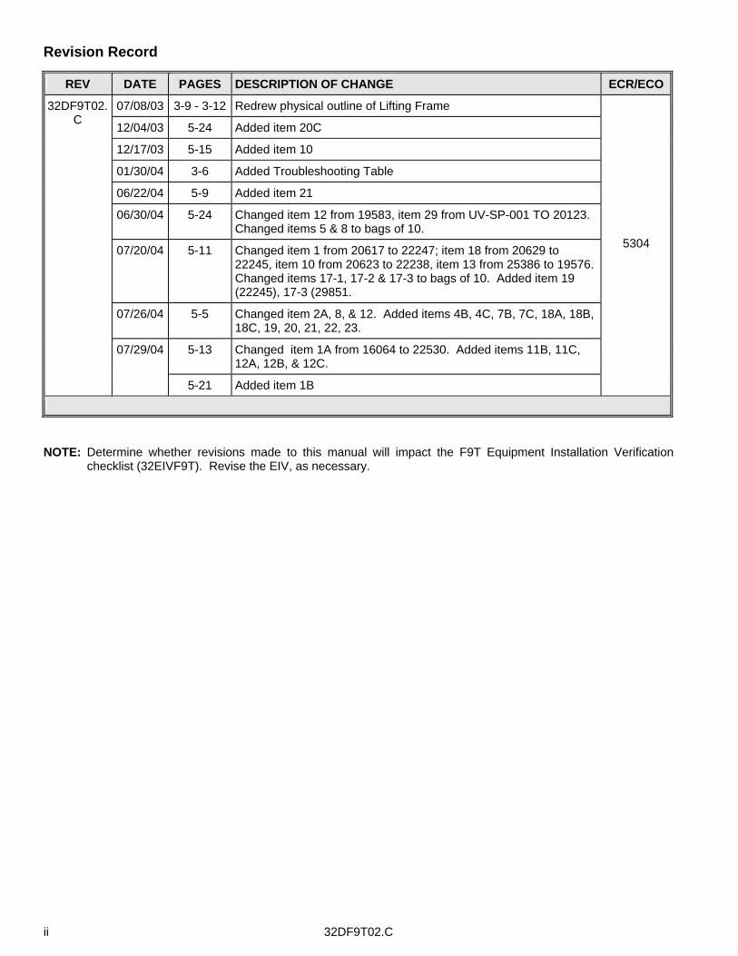
Revision Record
REV DATE PAGES DESCRIPTION OF CHANGE ECR/ECO
07/08/03 3-9 - 3-12 Redrew physical outline of Lifting Frame
12/04/03 5-24 Added item 20C
12/17/03 5-15 Added item 10
01/30/04 3-6 Added Troubleshooting Table
06/22/04 5-9 Added item 21
06/30/04 5-24 Changed item 12 from 19583, item 29 from UV-SP-001 TO 20123. Changed items 5 & 8 to bags of 10.
07/20/04 5-11 Changed item 1 from 20617 to 22247; item 18 from 20629 to 22245, item 10 from 20623 to 22238, item 13 from 25386 to 19576. Changed items 17-1, 17-2 & 17-3 to bags of 10. Added item 19 (22245), 17-3 (29851.
07/26/04 5-5 Changed item 2A, 8, & 12. Added items 4B, 4C, 7B, 7C, 18A, 18B, 18C, 19, 20, 21, 22, 23.
5-13 Changed item 1A from 16064 to 22530. Added items 11B, 11C, 12A, 12B, & 12C.
32DF9T02.C
07/29/04
5-21 Added item 1B
5304
NOTE: Determine whether revisions made to this manual will impact the F9T Equipment Installation Verification
checklist (32EIVF9T). Revise the EIV, as necessary.
32DF9T02.C iii
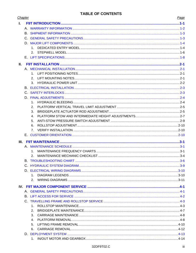
TABLE OF CONTENTS Chapter Page
I. F9T INTRODUCTION.........................................................................................................................1-1 A. WARRANTY INFORMATION .........................................................................................................................1-2 B. SHIPMENT INFORMATION ...........................................................................................................................1-3 C. GENERAL SAFETY PRECAUTIONS.............................................................................................................1-3 D. MAJOR LIFT COMPONENTS ........................................................................................................................1-4
1. DEDICATED ENTRY MODEL ................................................................................................................1-4 2. STEPWELL MODEL ...............................................................................................................................1-6
E. LIFT SPECIFICATIONS..................................................................................................................................1-8
II. F9T INSTALLATION ..........................................................................................................................2-1 A. MECHANICAL INSTALLATION......................................................................................................................2-1
1. LIFT POSITIONING NOTES...................................................................................................................2-1 2. LIFT MOUNTING NOTES.......................................................................................................................2-1 3. HYDRAULIC POWER UNIT ...................................................................................................................2-2
B. ELECTRICAL INSTALLATION .......................................................................................................................2-3 C. SAFETY INTERLOCKS ..................................................................................................................................2-3 D. FINAL ADJUSTMENTS ..................................................................................................................................2-4
1. HYDRAULIC BLEEDING........................................................................................................................2-4 2. PLATFORM VERTICAL TRAVEL LIMIT ADJUSTMENT .......................................................................2-5 3. BRIDGEPLATE ACTUATOR ROD ADJUSTMENT................................................................................2-5 4. PLATFORM STOW AND INTERMEDIATE HEIGHT ADJUSTMENTS..................................................2-7 5. ANTI-STOW PRESSURE SWITCH ADJUSTMENT ..............................................................................2-9 6. ROLLSTOP ADJUSTMENT..................................................................................................................2-10 7. VERIFY INSTALLATION ......................................................................................................................2-10
E. CUSTOMER ORIENTATION........................................................................................................................2-10
III. F9T MAINTENANCE..........................................................................................................................3-1 A. MAINTENANCE SCHEDULE .........................................................................................................................3-1
1. MAINTENANCE FREQUENCY CHARTS ..............................................................................................3-1 2. MAINTENANCE MECHANIC CHECKLIST ............................................................................................3-4
B. TROUBLESHOOTING CHART ......................................................................................................................3-6 C. HYDRAULIC SYSTEM DIAGRAM..................................................................................................................3-9 D. ELECTRICAL WIRING DIAGRAMS .............................................................................................................3-10
1. DIAGRAM LEGENDS...........................................................................................................................3-10 2. WIRING DIAGRAMS ............................................................................................................................3-11
IV. F9T MAJOR COMPONENT SERVICE ..............................................................................................4-1 A. GENERAL SAFETY PRECAUTIONS.............................................................................................................4-1 B. LIFT ACCESS FOR SERVICE .......................................................................................................................4-2 C. TRAVELLING FRAME AND ROLLSTOP SERVICE ......................................................................................4-3
1. ROLLSTOP MAINTENANCE..................................................................................................................4-3 2. BRIDGEPLATE MAINTENANCE............................................................................................................4-7 3. CARRIAGE MAINTENANCE..................................................................................................................4-8 4. PLATFORM REMOVAL..........................................................................................................................4-8 5. LIFTING FRAME REMOVAL................................................................................................................4-10 6. CARRIAGE REMOVAL.........................................................................................................................4-12
D. DEPLOYMENT SYSTEM .............................................................................................................................4-13 1. IN/OUT MOTOR AND GEARBOX........................................................................................................4-14
32DF9T02.C iv
2. DRIVE CHAINS.................................................................................................................................... 4-15 3. TORQUE LIMITING CLUTCH.............................................................................................................. 4-18 4. INTERMEDIATE SHAFT AND FINAL DRIVESHAFT .......................................................................... 4-19 5. MANUAL PLATFORM RELEASE MECHANISM ................................................................................. 4-20
E. HYDRAULIC POWER SYSTEM .................................................................................................................. 4-22 1. SYSTEM FLUID RENEWAL ................................................................................................................ 4-22 2. ELECTRIC PUMP MOTOR.................................................................................................................. 4-23 3. HYDRAULIC CYLINDER...................................................................................................................... 4-24 4. PRESSURE SWITCH ADJUSTMENT ................................................................................................. 4-25 5. HYDRAULIC HOSE AND MAIN ELECTRICAL HARNESS................................................................. 4-26
F. ELECTRICAL CONTROLS .......................................................................................................................... 4-27 1. GENERAL LIMIT SWITCH REPLACEMENT....................................................................................... 4-27 2. ELECTRONIC CONTROLLER REPLACEMENT ................................................................................ 4-27 3. HYDRAULIC HOSE AND MAIN ELECTRICAL HARNESS................................................................. 4-28
V. F9T SPARE PARTS...........................................................................................................................5-1
-RETURN TO FRONT COVER- -GO TO NEXT CHAPTER-
32DF9T02.C
1 - 1
I. F9T INTRODUCTION afe and easy access to mass-transit vehicles is provided by the RICON Mirage F9T Transit Use Wheelchair and Standee Lift. Refer to Figures 1-1 and 1-2. This manual covers both Dedicated Entry (DE) and Stepwell (SW) models. The Dedicated Entry model is intended for installation in a vehicle baggage bay, or similar com-
partment. The Stepwell model is installed within a vehicle stepwell. An electric-motor driven hydraulic pump assures smooth platform movement, with a maximum capacity of 660 pounds (300 kilograms). The vehicle operator, or a trained attendant, operates it. The operator uses control switches to with-draw the platform from the vehicle (deploy) and lower it to ground level. The passenger boards the large non-skid platform and is then raised to floor height. The passenger enters the vehicle, and then the operator lowers the plat-form and retracts it back into the vehicle (stow). When the passenger exits, the operator uses control switches to withdraw the platform from the vehicle (deploy) and raise it to floor height. The passenger boards the platform and is then lowered to the ground by the operator. The passenger departs, and the operator returns the platform to the stow position. One individual can manually operate the lift when normal power is not present. A manual release mechanism is provided to ease the task of pulling the platform out of its enclosure by hand. The hydraulic pump assembly includes a manually operated back-up pump to raise the platform, and a release valve to lower it. The front platform rollstop, normally power operated, has a manual override knob for back-up use. This manual contains general installation instructions, a maintenance chapter, a repair chapter, and a spare parts chapter. If you have questions about this manual, or need additional copies, please contact Ricon Product Support at one of the following locations:
Ricon Corporation 7900 Nelson Road Panorama City, CA 91402 . . . . .(818) 267-3000 Outside (818) Area Code . . . . .(800) 322-2884 World Wide Website . . . . .www.riconcorp.com
Ricon U.K. Ltd. Littlemoss Business Park, Littlemoss Road Droylsden, Manchester United Kingdom, M43 7EF . . . . .(+44) 161 301 6000
S
32DF9T02.C 1 - 2
A. F9T TWO-YEAR LIMITED WARRANTY
RICON CORPORATION ~ TWO-YEAR LIMITED WARRANTY ~
Ricon Corporation (Ricon) warrants to the original purchaser of this product that Ricon will repair or replace, at its option, any part that fails because of defective material or workmanship as follows: • Repair or replace parts for a period of two years from the date of purchase. A complete list of parts covered by this
warranty can be obtained from Ricon Product Support. • Labor costs for specified parts replaced under this warranty for a period of two years from the date put into service.
A Ricon rate schedule determines parts covered and labor allowed.
If You Need to Return a Product: Return this product to Ricon, following the Ricon RMA procedure. Please give as much advance notice as possi-ble, and allow a reasonable amount of time for repair.
This Warranty Does Not Cover: Malfunction or damage to product parts caused by: accident, misuse, lack of proper maintenance, neglect, im-proper adjustment, modification, alteration, the mechanical condition of the vehicle, road hazards, overloading, fail-ure to follow operating instructions, or acts of Nature (i.e., weather, lightning, flood).
NOTE: Ricon recommends this product be inspected by a Ricon authorized service technician at least once every six months, or sooner if necessary. Any required maintenance should be performed at that time.
WARNING! THIS PRODUCT HAS BEEN DESIGNED AND MANUFACTURED TO EXACT SPECIFICATIONS.
— MODIFICATION OF THIS PRODUCT CAN BE DANGEROUS —
This Warranty is Void If: • The product is not installed and maintained by a Ricon authorized service technician. • The product is modified or altered in any respect from its original design without written authorization by Ricon.
Ricon disclaims liability for any personal injury or property damage that results from operation of a Ricon product that has been modified from the original Ricon design. No person or company is authorized to change the de-sign of this Ricon product without written authorization by Ricon.
Ricon's obligation under this warranty is exclusively limited to the repair or exchange of parts that fail within the warranty period.
Ricon assumes no responsibility for expenses or damages, including incidental or consequential damages. Some states do not allow the exclusion or limitation of incidental or consequential damages, so the above limita-tion or exclusion may not apply.
Important: The warranty registration card must be completed and returned to Ricon within twenty days after in-stallation of this Ricon product for the warranty to be valid. The warranty is not transferable.
The warranty gives specific legal rights. There may be other rights that vary in each state.
32DF9T02.C
1 - 3
B. SHIPMENT INFORMATION Verify that lift installation kit, if supplied, contains all items listed on kit packing list. Please report any missing items immediately to Ricon Product Support. The warranty and owner registration cards must be completed and returned to Ricon within 20 days to validate warranty.
NOTE: Sales or Service Personnel must review the Warranty and the Operator Manual with the user to confirm that they know how to safely operate the product. Instruct the user to follow operating instructions without ex-ception.
C. GENERAL SAFETY PRECAUTIONS Follow the general safety precautions during installation, operation, service, and maintenance: Do not attempt maintenance, repairs, or adjustments without the presence of a person capable of
rendering aid. Take notice of all injuries, regardless of how slight. Administer first aid or seek medical attention
immediately. Wear protective eye shields and appropriate clothing at all times. Work in a properly ventilated area. Do not smoke, or use an open flame, near the battery. Exercise caution when operating lift to avoid injury. Be certain that hands, feet, legs and clothing are
not in path of the platform as it moves. Be cautious when using metallic (conductive) tools near the battery, or heavy gauge wires. If battery acid contacts skin, wash area immediately with soap and water. Check under vehicle before drilling or cutting to avoid damage to the frame, subframe members, wir-
ing, hydraulic lines, etc. Thoroughly understand the operating instructions before attempting to operate lift. Inspect lift before each use. Do not operate lift if an unsafe condition is present, or if there are un-
usual noises or movements. Keep others clear during lift operation. Maintain the lift at its highest level of performance by doing the required maintenance. Ricon recom-
mends a thorough inspection every six months.
32DF9T02.C 1 - 4
D. MAJOR LIFT COMPONENTS
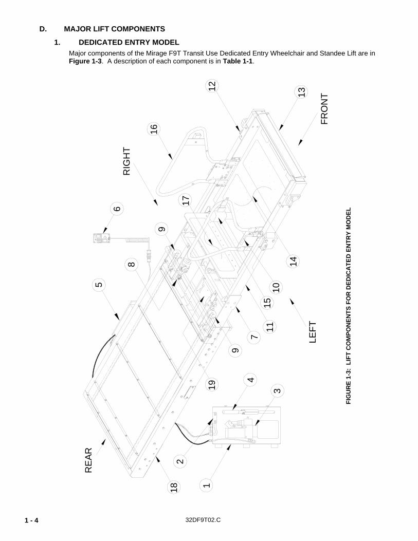
1. DEDICATED ENTRY MODEL Major components of the Mirage F9T Transit Use Dedicated Entry Wheelchair and Standee Lift are in Figure 1-3. A description of each component is in Table 1-1.
1
2
3
4
5
6
7
8
9
1011
1312
14
15
16
17
19
FRO
NT
RIG
HT
LEFT
RE
AR
9
18
FIG
UR
E 1-
3: L
IFT
CO
MPO
NEN
TS F
OR
DED
ICA
TED
EN
TRY
MO
DEL
32DF9T02.C
1 - 5
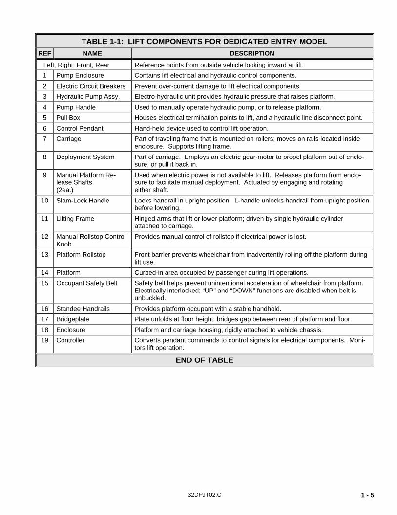
TABLE 1-1: LIFT COMPONENTS FOR DEDICATED ENTRY MODEL REF NAME DESCRIPTION
Left, Right, Front, Rear Reference points from outside vehicle looking inward at lift. 1 Pump Enclosure Contains lift electrical and hydraulic control components. 2 Electric Circuit Breakers Prevent over-current damage to lift electrical components. 3 Hydraulic Pump Assy. Electro-hydraulic unit provides hydraulic pressure that raises platform. 4 Pump Handle Used to manually operate hydraulic pump, or to release platform. 5 Pull Box Houses electrical termination points to lift, and a hydraulic line disconnect point. 6 Control Pendant Hand-held device used to control lift operation. 7 Carriage Part of traveling frame that is mounted on rollers; moves on rails located inside
enclosure. Supports lifting frame. 8 Deployment System Part of carriage. Employs an electric gear-motor to propel platform out of enclo-
sure, or pull it back in. 9 Manual Platform Re-
lease Shafts (2ea.)
Used when electric power is not available to lift. Releases platform from enclo-sure to facilitate manual deployment. Actuated by engaging and rotating either shaft.
10 Slam-Lock Handle Locks handrail in upright position. L-handle unlocks handrail from upright position before lowering.
11 Lifting Frame Hinged arms that lift or lower platform; driven by single hydraulic cylinder attached to carriage.
12 Manual Rollstop Control Knob
Provides manual control of rollstop if electrical power is lost.
13 Platform Rollstop Front barrier prevents wheelchair from inadvertently rolling off the platform during lift use.
14 Platform Curbed-in area occupied by passenger during lift operations. 15 Occupant Safety Belt Safety belt helps prevent unintentional acceleration of wheelchair from platform.
Electrically interlocked; “UP” and “DOWN” functions are disabled when belt is unbuckled.
16 Standee Handrails Provides platform occupant with a stable handhold. 17 Bridgeplate Plate unfolds at floor height; bridges gap between rear of platform and floor. 18 Enclosure Platform and carriage housing; rigidly attached to vehicle chassis. 19 Controller Converts pendant commands to control signals for electrical components. Moni-
tors lift operation.
END OF TABLE
32DF9T02.C 1 - 6
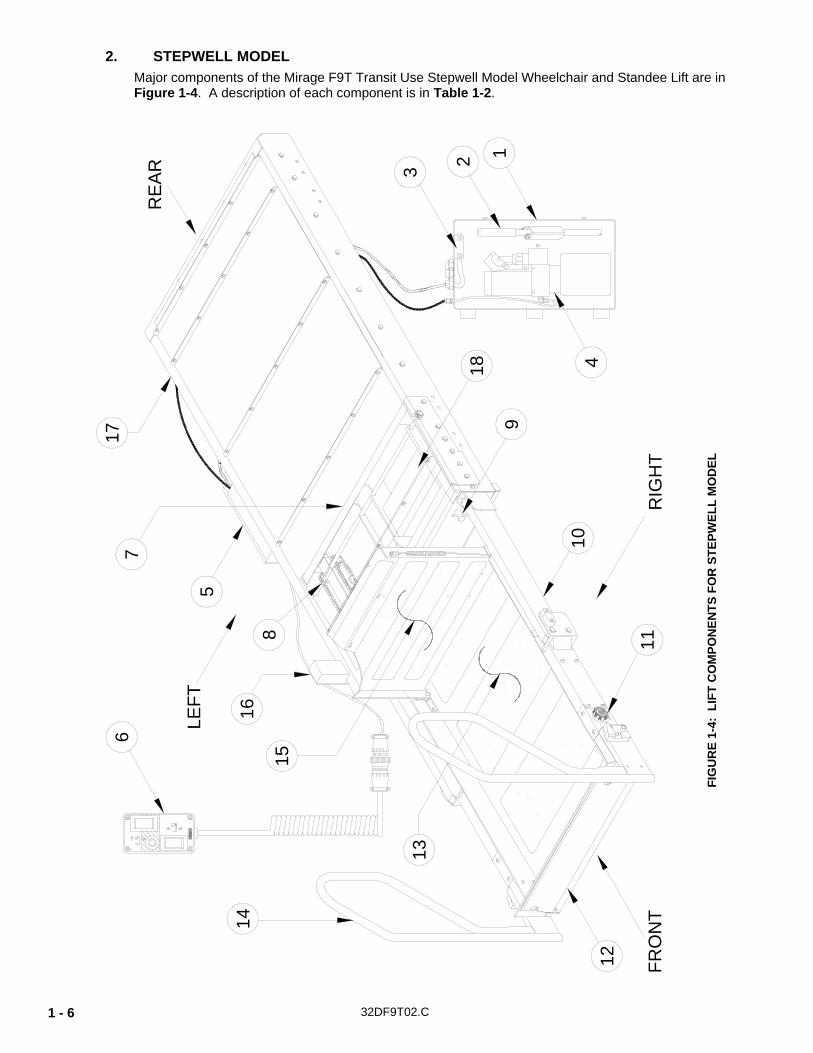
2. STEPWELL MODEL Major components of the Mirage F9T Transit Use Stepwell Model Wheelchair and Standee Lift are in Figure 1-4. A description of each component is in Table 1-2.
RE
AR
10
17
RIG
HT
2
12
13
11FR
ON
T
18
7
168
9
14
15
5LE
FT
6
4
3
1
FIG
UR
E 1-
4: L
IFT
CO
MPO
NEN
TS F
OR
STE
PWEL
L M
OD
EL
32DF9T02.C
1 - 7
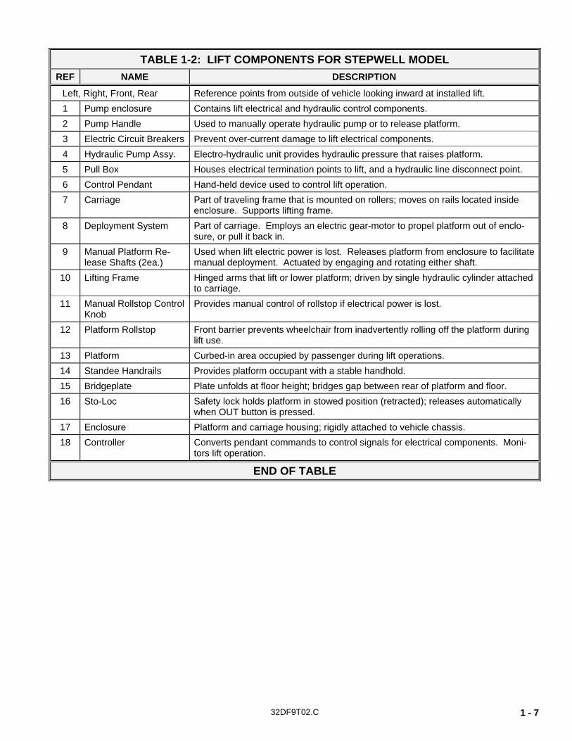
TABLE 1-2: LIFT COMPONENTS FOR STEPWELL MODEL REF NAME DESCRIPTION
Left, Right, Front, Rear Reference points from outside of vehicle looking inward at installed lift. 1 Pump enclosure Contains lift electrical and hydraulic control components. 2 Pump Handle Used to manually operate hydraulic pump or to release platform. 3 Electric Circuit Breakers Prevent over-current damage to lift electrical components. 4 Hydraulic Pump Assy. Electro-hydraulic unit provides hydraulic pressure that raises platform. 5 Pull Box Houses electrical termination points to lift, and a hydraulic line disconnect point. 6 Control Pendant Hand-held device used to control lift operation. 7 Carriage Part of traveling frame that is mounted on rollers; moves on rails located inside
enclosure. Supports lifting frame. 8 Deployment System Part of carriage. Employs an electric gear-motor to propel platform out of enclo-
sure, or pull it back in. 9 Manual Platform Re-
lease Shafts (2ea.) Used when lift electric power is lost. Releases platform from enclosure to facilitate manual deployment. Actuated by engaging and rotating either shaft.
10 Lifting Frame Hinged arms that lift or lower platform; driven by single hydraulic cylinder attached to carriage.
11 Manual Rollstop Control Knob
Provides manual control of rollstop if electrical power is lost.
12 Platform Rollstop Front barrier prevents wheelchair from inadvertently rolling off the platform during lift use.
13 Platform Curbed-in area occupied by passenger during lift operations. 14 Standee Handrails Provides platform occupant with a stable handhold. 15 Bridgeplate Plate unfolds at floor height; bridges gap between rear of platform and floor. 16 Sto-Loc Safety lock holds platform in stowed position (retracted); releases automatically
when OUT button is pressed. 17 Enclosure Platform and carriage housing; rigidly attached to vehicle chassis. 18 Controller Converts pendant commands to control signals for electrical components. Moni-
tors lift operation.
END OF TABLE
32DF9T02.C 1 - 8
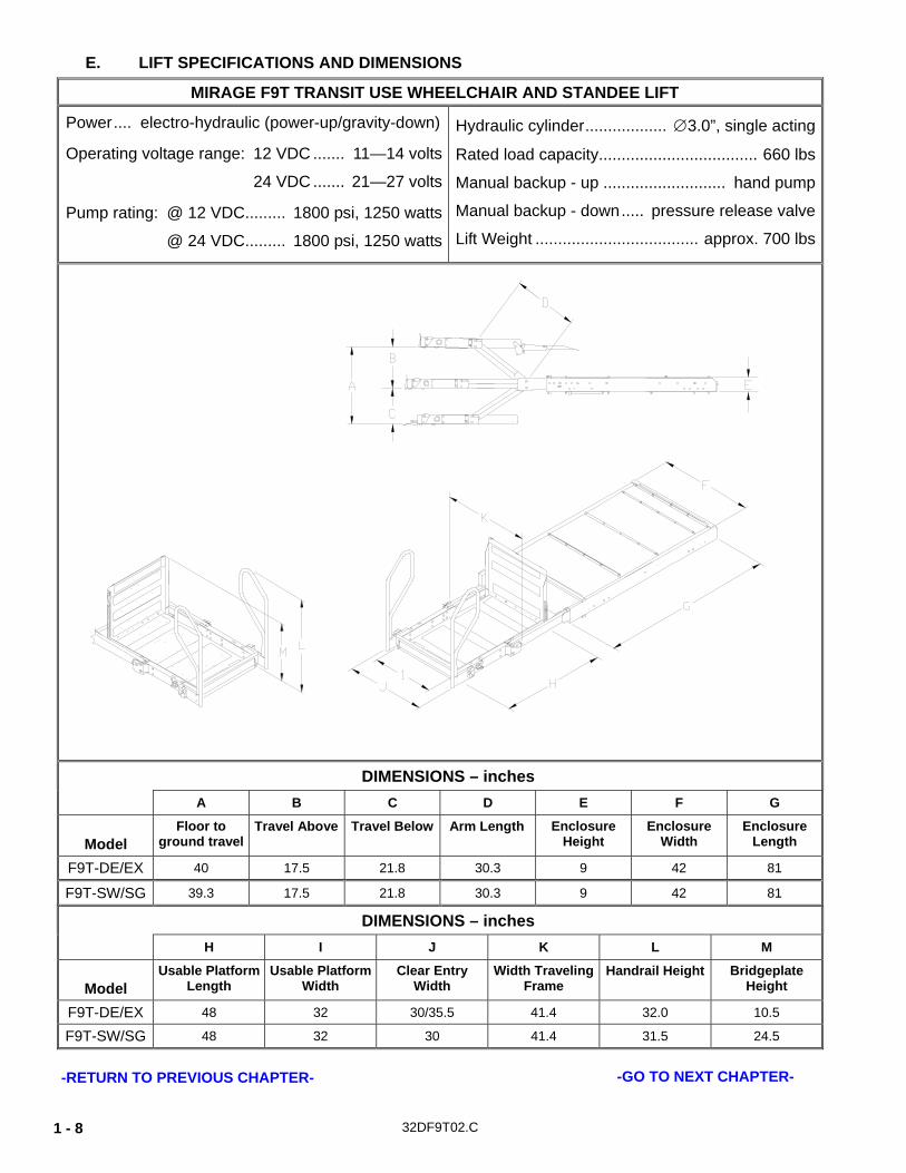
E. LIFT SPECIFICATIONS AND DIMENSIONS
MIRAGE F9T TRANSIT USE WHEELCHAIR AND STANDEE LIFT
Power.... electro-hydraulic (power-up/gravity-down)
Operating voltage range: 12 VDC ....... 11—14 volts
24 VDC ....... 21—27 volts
Pump rating: @ 12 VDC......... 1800 psi, 1250 watts
@ 24 VDC......... 1800 psi, 1250 watts
Hydraulic cylinder.................. ∅3.0”, single acting
Rated load capacity................................... 660 lbs
Manual backup - up ........................... hand pump
Manual backup - down..... pressure release valve
Lift Weight .................................... approx. 700 lbs
DIMENSIONS – inches A B C D E F G
Model
Floor to ground travel
Travel Above Travel Below Arm Length Enclosure Height
Enclosure Width
Enclosure Length
F9T-DE/EX 40 17.5 21.8 30.3 9 42 81
F9T-SW/SG 39.3 17.5 21.8 30.3 9 42 81
DIMENSIONS – inches H I J K L M
Model
Usable Platform Length
Usable Platform Width
Clear Entry Width
Width Traveling Frame
Handrail Height Bridgeplate Height
F9T-DE/EX 48 32 30/35.5 41.4 32.0 10.5
F9T-SW/SG 48 32 30 41.4 31.5 24.5
-RETURN TO PREVIOUS CHAPTER- -GO TO NEXT CHAPTER-
32DF9T02.C 2 - 1
II. F9T INSTALLATION he RICON Mirage F9T Transit Use Wheelchair and Standee Lift is contained in an enclosure, which can be mounted in several possible vehicle locations. Specific information for every possible installation is not provided due to the wide range of applications. Most illustrations used in this chapter apply to both the Dedicated Entry model and Stepwell model.
Therefore, some views could appear reversed compared to the application being worked on. The following general procedures apply to most installations. Contact Ricon Product Support for information on installations not covered. Installation is carried out in four steps:
1. Mechanical 2. Electrical 3. Final Adjustments 4. Installation Verification
A. MECHANICAL 1. LIFT POSITIONING NOTES
Select a location within vehicle to install lift. The exact mounting position is determined by the motion path of the lift platform, relative to the ground and the vehicle interior floor. The lift must move without obstruction through its range of travel.
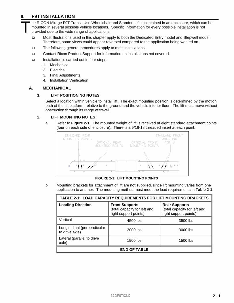
2. LIFT MOUNTING NOTES a. Refer to Figure 2-1. The mounted weight of lift is received at eight standard attachment points
(four on each side of enclosure). There is a 5/16-18 threaded insert at each point.
b. Mounting brackets for attachment of lift are not supplied, since lift mounting varies from one application to another. The mounting method must meet the load requirements in Table 2-1.
TABLE 2-1: LOAD CAPACITY REQUIREMENTS FOR LIFT MOUNTING BRACKETS
Loading Direction Front Supports (total capacity for left and right support points)
Rear Supports (total capacity for left and right support points)
Vertical 4500 lbs 3500 lbs
Longitudinal (perpendicular to drive axle) 3000 lbs 3000 lbs
Lateral (parallel to drive axle) 1500 lbs 1500 lbs
END OF TABLE
T
FIGURE 2-1: LIFT MOUNTING POINTS
32DF9T02.C 2 - 2
CAUTION! It is important that fasteners used for lift mounting do not protrude into the lift interior. Fasteners that are too long can interfere with movement of carriage.
c. Threaded fasteners for mounting lift are 5/16-18, and must be grade 5, or higher. Their length must provide at least 5/16” and no more than 7/16” of thread engagement with threaded inserts.
d. If adjustment slots are added to mounting brackets, they must be horizontal. Horizontal slots, rather than vertical, will prevent the lift slipping downward if the hardware loosens.
e. Vertical adjustment must be accomplished placing shims between the mounting brackets and vehicle frame. Maximum shim thickness is 1/8”.
f. Use at least two mounting points at each corner of enclosure to support lift.
g. The top four corners of the enclosure must be in the same plane, +/- 1/8”. Shim, as required.
h. Mounting brackets must be painted or treated to protect against rust and corrosion.
3. HYDRAULIC POWER UNIT
a. Hydraulic Power Unit Mounting Notes ♦ The hydraulic power unit must be located so that operator has a clear view of platform while
operating manual back-up system. ♦ The load capacity of brackets used to mount hydraulic power unit must meet criteria in
Table 2-2:
TABLE 2-2: LOAD CAPACITY REQUIREMENTS FOR HYDRAULIC POWER UNIT MOUNTING BRACKETS
LOAD DIRECTION BRACKET CAPACITY
Vertical 125 lb Longitudinal (perpendicular to drive axles) 200 lb Lateral (parallel to drive axles) 100 lb
END OF TABLE
♦ Meeting these criteria assures that the pump mounting will withstand normal loads occuring during transit, and also during manual pump use.
♦ Be certain pick-up tube is oriented properly when pump assembly is horizontally mounted. Also, be certain breather plug oriented properly (requires elbow fitting).
b. Power Unit to Pull Box Connection 1) Connect main hydraulic hose to hydraulic power unit, if not already done. 2) Operate manual backup pump until hydraulic fluid flows out open end of hose. 3) Connect open end of hose to hydraulic fitting located on side of pull-box. 4) Deploy platform and lower to ground.
CAUTION! Check and add hydraulic fluid when platform is at ground level. Adding fluid with platform raised will cause oil reservoir to overflow when it is lowered.
5) Remove temporary plug on top of hydraulic pump reservoir. Verify that hydraulic fluid in reservoir is at FULL level. Add Texaco 01554 Aircraft Hydraulic Oil, or equivalent U.S. mil spec H5606G fluid, if necessary. Replace temporary plug with supplied breather plug.
6) Refer to Final Adjustments section in this chapter for hydraulic bleeding procedure.
32DF9T02.C 2 - 3
B. ELECTRICAL Electrical installation is similar for both 12 and 24 VDC electrical systems, whether they are insulated return, or chassis return. Use the following procedure to connect power to lift.
NOTE: A dedicated, insulated 4 AWG return (ground) wire is recommended. In either case, be certain all connections are clean and strong.
CAUTION! Check vehicle before drilling. Do not drill into factory wiring, hydraulic lines, fuel lines, fuel tank, etc.
1. Mount a circuit breaker (50 amp for 24V application, and 90 amp for 12V) within 12” (30 cm) of battery.
2. Cut one 3/4" (19.5-mm) hole through vehicle floor or wall to gain access to underside of vehicle. Locate hole adjacent to hydraulic pump unit. Deburr hole and install rubber grommet.
3. Crimp a 5/16” ring terminal to end of four gauge, red power cable, then fasten to power cut-off solenoid (located near hydraulic pump unit). Insert other end of red wire through grommet.
CAUTION! When routing power cable, avoid hazards such as drive- shafts, moving suspension parts, exhaust system, etc.
4. Route cable along vehicle frame, etc, to circuit breaker location. Make sure cable does not interfere with moving parts or contact anything hot. Secure with cable ties every 18” (45 cm).
5. Cut red wire to an appropriate length for reaching the circuit breaker. Save the discarded wire. 6. Crimp a ¼” ring terminal to end of red wire, then fasten to circuit breaker AUX terminal. 7. Cut a 12" (30 cm) length of wire from the previously saved heavy red wire, and crimp a ¼” ring
terminal to both ends. 8. Fasten one end of wire to circuit breaker BAT terminal.
WARNING! • WEAR PROTECTIVE CLOTHING AND EYE PROTECTION AT ALL TIMES. BATTERIES
CONTAIN ACID THAT CAN BURN. IF ACID COMES INTO CONTACT WITH SKIN, IM-MEDIATELY FLUSH AFFECTED AREA WITH WATER AND WASH WITH SOAP.
• ALWAYS WORK IN A PROPERLY VENTILATED AREA. DO NOT SMOKE OR USE AN OPEN FLAME IN THE VICINITY OF BATTERY.
• DO NOT LAY ANYTHING METALLIC ON TOP OF BATTERY.
9. Fasten other end of wire to POSITIVE (+) battery terminal. 10. Connect supplied harness between terminal strip in hydraulic pump enclosure and terminal strip in
pull box. Connect harness to pendant (or to pendant extension). Refer to electrical diagrams in Chapter III.
C. SAFETY INTERLOCKS
WARNING! • THE LIFT CONTROLS MUST BE DISABLED ANYTIME THE VEHICLE IS NOT SAFELY
PARKED. VERIFY THAT LIFT OPERATION CONFORMS TO ADA CODE 49 CFR.
• INSTALLATION OF SAFETY INTERLOCKS FOR COMPLIANCE WITH ADA REQUIRE-MENTS IS THE RESPONSIBILITY OF THE INSTALLER.
Refer to wiring diagrams in Chapter III. A voltage that is sourced from vehicle (12 or 24 VDC) is applied to terminal five of the pump enclosure terminal strip WHEN VEHICLE IS SAFELY PARKED. This complies with ADA interlock requirements.
32DF9T02.C 2 - 4
D. FINAL ADJUSTMENTS This section contains procedures that might be needed after lift is installed in vehicle. It is not a requirement to perform all procedures after lift installation, but only those that are necessary. Additional adjustment procedures, that would normally be needed after maintenance or repair, are in Chapter IV.
WARNING! FAILURE TO PROPERLY ADJUST EQUIPMENT MAY RESULT IN UNSAFE OPERATING CONDITIONS FOR THE LIFT USER.
1. HYDRAULIC BLEEDING The fluid in hydraulic system will contain air after installation of lift into vehicle. It may also contain air as a result of doing maintenance or repairs. The trapped air must be removed by "bleeding" the hydraulic system. Two methods are possible. The first is a traditional procedure that requires opening the hydraulic system. The second procedure is quicker and easier because it does not require any disassembly. However, the second procedure will not remove air as thoroughly as the first.
a. TYPICAL BLEEDING PROCEDURE NOTE: The following procedure should be performed by two people, and may spill hydraulic fluid.
1) Fully deploy lift. 2) Raise platform to floor height, and support.
WARNING! THE SERVICE ACCESS PANEL IS HINGED ALONG THE REAR EDGE AND SHOULD BE HELD UP WHILE REMOVING THE RETAINING SCREWS AT THE FRONT EDGE. THIS WILL PREVENT PANEL FROM FALLING AND CAUSING INJURY OR DAMAGE.
3) To gain access to underside of lift, hold service access panel up, remove the two retaining screws and lock-nuts near front edge of panel, and then lower panel.
WARNING! C WEAR PROTECTIVE CLOTHING AND EYE PROTECTION AT ALL TIMES. BAT-
TERIES CONTAIN ACID THAT CAN BURN. IF ACID COMES INTO CONTACT WITH SKIN, IMMEDIATELY FLUSH AFFECTED AREA WITH WATER AND WASH WITH SOAP.
C ALWAYS WORK IN A PROPERLY VENTILATED AREA. DO NOT SMOKE OR USE AN OPEN FLAME IN THE VICINITY OF BATTERY.
C DO NOT LAY ANYTHING METALLIC ON TOP OF BATTERY.
4) Disconnect positive battery (+) cable in vehicle battery compartment. 5) Locate air bleeder valve on top side of hydraulic cylinder (cylinder located in carriage).
Access to this valve is through a hole in the rear carriage frame channel. 6) Remove platform support.
WARNING! THE FOLLOWING STEP OPENS THE HYDRAULIC BLEEDER VALVE AND WILL ALLOW THE PLATFORM TO SLOWLY DROP.
NOTE: This step will spill hydraulic fluid; have dry rags on hand. 7) Open bleeder valve slightly. Let air and hydraulic fluid escape from cylinder. 8) Close air bleeder valve.
9) Manually lower platform to ground.
CAUTION! Check and add hydraulic fluid when platform is at ground level. Adding fluid with platform raised will cause oil reservoir to overflow when it is lowered.
32DF9T02.C 2 - 5
10) Remove plug on the top of hydraulic pump tank (reservoir). Make sure that hydraulic fluid in tank is at FULL level. Add only Texaco 01554 Aircraft Hydraulic Oil, or equivalent U.S. mil spec H5606G fluid and reinstall plug.
11) Repeat previous five steps until fluid coming out of bleeder valve is free of air. 12) Verify that air bleeder valve is fully closed. 13) Hold service access panel up, remove two retaining screws and lock-nuts at front edge of
panel, and then lower panel. 14) Connect positive (+) battery cable at vehicle battery compartment. 15) Remove platform support and stow platform.
b. ALTERNATE BLEEDING PROCEDURE 1) Connect hydraulic hose to fitting on pump box, if not already connected. 2) Use manual pump to fill hose; fluid should flow from open end. 3) Connect open end of hose to fitting on pull box. 4) Verify that top of enclosure is about 40” above ground, and that enclosure is level. 5) Deploy platform and lower until maximum down travel is obtained. 6) Raise platform to floor level. 7) Repeat above cycle ten times.
2. PLATFORM VERTICAL TRAVEL LIMIT ADJUSTMENT
CAUTION! The following procedure measures and sets the platform height at floor level. Adjustments to platform height are made at a lower height to reduce loading on the hydraulic cylinder piston. Do not attempt to rotate hydraulic cylinder piston rod if excessive resistance is felt. Determine cause of resistance, and correct before rotating piston rod.
NOTE: This procedure should be used to adjust vertical travel limit errors of less than 1”. Errors greater than 1” must be adjusted by supporting platform, removing keeper plates (2 ea), and rotating the trunnion.
a. Raise platform until hydraulic cylinder is fully extended. b. Measure vertical distance between floor and rear edge of platform. The platform must be 1–1½”
above the floor. Note the amount of error, and whether platform needs to be raised or lowered. Continue this procedure, if adjustment is necessary.
c. Lower the platform to a height about one foot below floor level, and support it. d. Loosen jam nut on hydraulic cylinder piston rod. e. Rotate piston rod to raise or lower platform the required amount; rotate CW to raise platform and
CCW to lower. Do not rotate piston rod more than ¼ turn without checking result. f. Return platform to floor height (fully extend hydraulic cylinder), and remeasure the distance
between floor and platform. If readjustment is necessary, repeat steps b through f. g. Tighten jam nut.
NOTE: Reprogram the stow height (and intermediate height, if lift is installed in baggage bay) if an adjustment was made. Refer to the Platform Stow Height Adjustment section in this chapter.
3. BRIDGEPLATE ACTUATOR ROD ADJUSTMENT Bridgeplate deployment is controlled by two actuator rods. The length of the rods control the angle of the bridgeplate relative to the platform. Adjust actuator rods so bridgeplate is fully unfolded when platform arrives at floor height.
WARNING! INCORRECT DEPLOYMENT OF BRIDGEPLATE CAN CREATE A DANGEROUS CONDITION FOR LIFT USER, AND MAY CAUSE DAMAGE TO THE BRIDGE PLATE OR PLATFORM. VERIFY THAT THE BRIDGEPLATE IS ADJUSTED CORRECTLY.
a. Deploy platform using control pendant ( /OUT). b. Raise platform to floor height and support it.
32DF9T02.C 2 - 6
WARNING! C WEAR PROTECTIVE CLOTHING AND EYE PROTECTION AT ALL TIMES. BATTERIES
CONTAIN ACID THAT CAN BURN. IF ACID COMES INTO CONTACT WITH SKIN, IM-MEDIATELY FLUSH AFFECTED AREA WITH WATER AND WASH WITH SOAP.
C ALWAYS WORK IN A PROPERLY VENTILATED AREA. DO NOT SMOKE OR USE OPEN FLAME IN THE VICINITY OF BATTERY.
C DO NOT LAY ANYTHING ON TOP OF BATTERY.
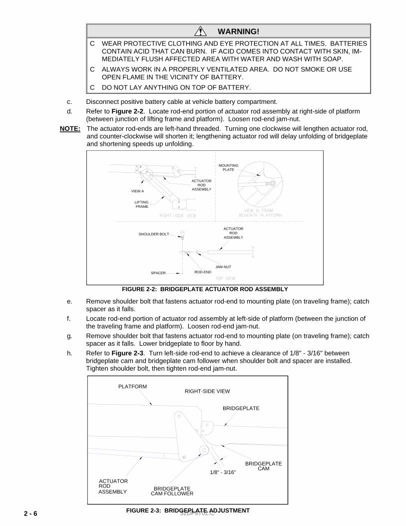
c. Disconnect positive battery cable at vehicle battery compartment. d. Refer to Figure 2-2. Locate rod-end portion of actuator rod assembly at right-side of platform
(between junction of lifting frame and platform). Loosen rod-end jam-nut. NOTE: The actuator rod-ends are left-hand threaded. Turning one clockwise will lengthen actuator rod,
and counter-clockwise will shorten it; lengthening actuator rod will delay unfolding of bridgeplate and shortening speeds up unfolding.
e. Remove shoulder bolt that fastens actuator rod-end to mounting plate (on traveling frame); catch spacer as it falls.
f. Locate rod-end portion of actuator rod assembly at left-side of platform (between the junction of the traveling frame and platform). Loosen rod-end jam-nut.
g. Remove shoulder bolt that fastens actuator rod-end to mounting plate (on traveling frame); catch spacer as it falls. Lower bridgeplate to floor by hand.
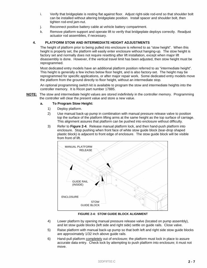
h. Refer to Figure 2-3. Turn left-side rod-end to achieve a clearance of 1/8" - 3/16" between bridgeplate cam and bridgeplate cam follower when shoulder bolt and spacer are installed. Tighten shoulder bolt, then tighten rod-end jam-nut.
1/8" - 3/16"
BRIDGEPLATE
PLATFORM
BRIDGEPLATECAM FOLLOWER
RIGHT-SIDE VIEW
CAMBRIDGEPLATE
RODACTUATOR
ASSEMBLY
FIGURE 2-3: BRIDGEPLATE ADJUSTMENT
SHOULDER BOLT
JAM-NUTROD-END
ACTUATORROD
ASSEMBLY
SPACER
ACTUATOR
ASSEMBLYROD
VIEW A
MOUNTINGPLATE
LIFTINGFRAME
FIGURE 2-2: BRIDGEPLATE ACTUATOR ROD ASSEMBLY
32DF9T02.C 2 - 7
i. Verify that bridgeplate is resting flat against floor. Adjust right-side rod-end so that shoulder bolt can be installed without altering bridgeplate position. Install spacer and shoulder bolt, then tighten rod-end jam-nut.
j. Reconnect positive battery cable at vehicle battery compartment. k. Remove platform support and operate lift to verify that bridgeplate deploys correctly. Readjust
actuator rod assemblies, if necessary.
4. PLATFORM STOW AND INTERMEDIATE HEIGHT ADJUSTMENTS The height of platform prior to being pulled into enclosure is referred to as “stow height”. When this height is properly set, the platform will easily enter enclosure without hanging-up. The stow height is factory set and normally does not require resetting after lift installation, except when major lift disassembly is done. However, if the vertical travel limit has been adjusted, then stow height must be reprogrammed. Most dedicated entry models have an additional platform position referred to as “intermediate height”. This height is generally a few inches below floor height, and is also factory-set. The height may be reprogrammed for specific applications, or after major repair work. Some dedicated entry models move the platform from the ground directly to floor height, without an intermediate stop. An optional programming switch kit is available to program the stow and intermediate heights into the controller memory. It is Ricon part number 17885.
NOTE: The stow and intermediate height values are stored indefinitely in the controller memory. Programming the controller will clear the present value and store a new value. a. To Program Stow Height:
1) Deploy platform. 2) Use manual back-up pump in combination with manual pressure release valve to position
top the surface of the platform lifting arms at the same height as the top surface of carriage. This alignment assures that platform can be pushed into enclosure without difficulty.
3) Refer to Figure 2-4. Release manual platform lock, and then hand-push platform into enclosure. Stop pushing when front face of white stow guide block (tear-drop shaped plastic block) is adjacent to front edge of enclosure. The stow guide block will be visible from front of lift.
4) Lower platform by opening manual pressure release valve (located on pump assembly), and let stow guide blocks (left side and right side) settle on guide rails. Close valve.
5) Raise platform with manual back-up pump so that both left and right side stow guide blocks are approximately 1/32 inch above guide rails.
6) Hand-pull platform completely out of enclosure; the platform must lock in place to assure accurate data entry. Check lock by attempting to push platform into enclosure; it must not move.
FIGURE 2-4: STOW GUIDE BLOCK ALIGNMENT
GUIDE RAIL(INSIDE)
STOWGUIDE BLOCK
RELEASEMANUAL PLATFORM
ENCLOSURE
32DF9T02.C 2 - 8
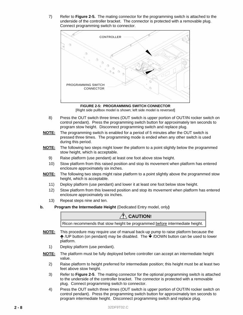
7) Refer to Figure 2-5. The mating connector for the programming switch is attached to the underside of the controller bracket. The connector is protected with a removable plug. Connect programming switch to connector.
8) Press the OUT switch three times (OUT switch is upper portion of OUT/IN rocker switch on control pendant). Press the programming switch button for approximately ten seconds to program stow height. Disconnect programming switch and replace plug.
NOTE: The programming switch is enabled for a period of 5 minutes after the OUT switch is pressed three times. The programming mode is ended when any other switch is used during this period.
NOTE: The following two steps might lower the platform to a point slightly below the programmed stow height, which is acceptable.
9) Raise platform (use pendant) at least one foot above stow height. 10) Stow platform from this raised position and stop its movement when platform has entered
enclosure approximately six inches. NOTE: The following two steps might raise platform to a point slightly above the programmed stow
height, which is acceptable. 11) Deploy platform (use pendant) and lower it at least one foot below stow height. 12) Stow platform from this lowered position and stop its movement when platform has entered
enclosure approximately six inches. 13) Repeat steps nine and ten.
b. Program the Intermediate Height (Dedicated Entry model, only)
CAUTION! Ricon recommends that stow height be programmed before intermediate height.
NOTE: This procedure may require use of manual back-up pump to raise platform because the /UP button (on pendant) may be disabled. The /DOWN button can be used to lower
platform. 1) Deploy platform (use pendant).
NOTE: The platform must be fully deployed before controller can accept an intermediate height value.
2) Raise platform to height preferred for intermediate position; this height must be at least two feet above stow height.
3) Refer to Figure 2-5. The mating connector for the optional programming switch is attached to the underside of the controller bracket. The connector is protected with a removable plug. Connect programming switch to connector.
4) Press the OUT switch three times (OUT switch is upper portion of OUT/IN rocker switch on control pendant). Press the programming switch button for approximately ten seconds to program intermediate height. Disconnect programming switch and replace plug.
FIGURE 2-5: PROGRAMMING SWITCH CONNECTOR[Right side pullbox model is shown; left side model is reversed]
PROGRAMMING SWITCHCONNECTOR
CONTROLLER
32DF9T02.C 2 - 9
NOTE: After the OUT switch is pressed three times, there is a time period of 5 minutes during which the programming switch is enabled. Programming will be disabled if any other switch is used during this period.
5) Verify that programmed intermediate position is correct by stowing platform, then deploying and raising it to intermediate height.
NOTE: It is acceptable for the intermediate position to vary +/- ½ inch from the programmed height.
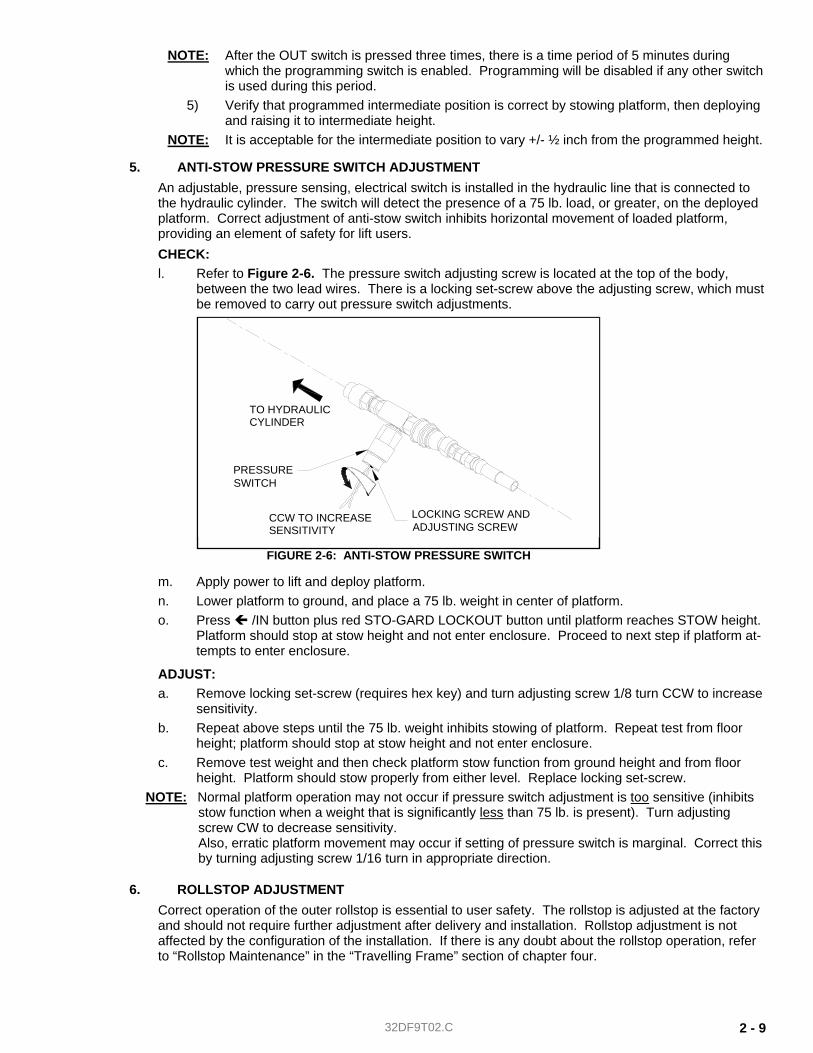
5. ANTI-STOW PRESSURE SWITCH ADJUSTMENT An adjustable, pressure sensing, electrical switch is installed in the hydraulic line that is connected to the hydraulic cylinder. The switch will detect the presence of a 75 lb. load, or greater, on the deployed platform. Correct adjustment of anti-stow switch inhibits horizontal movement of loaded platform, providing an element of safety for lift users. CHECK: l. Refer to Figure 2-6. The pressure switch adjusting screw is located at the top of the body,
between the two lead wires. There is a locking set-screw above the adjusting screw, which must be removed to carry out pressure switch adjustments.
m. Apply power to lift and deploy platform. n. Lower platform to ground, and place a 75 lb. weight in center of platform. o. Press /IN button plus red STO-GARD LOCKOUT button until platform reaches STOW height.
Platform should stop at stow height and not enter enclosure. Proceed to next step if platform at-tempts to enter enclosure.
ADJUST: a. Remove locking set-screw (requires hex key) and turn adjusting screw 1/8 turn CCW to increase
sensitivity. b. Repeat above steps until the 75 lb. weight inhibits stowing of platform. Repeat test from floor
height; platform should stop at stow height and not enter enclosure. c. Remove test weight and then check platform stow function from ground height and from floor
height. Platform should stow properly from either level. Replace locking set-screw. NOTE: Normal platform operation may not occur if pressure switch adjustment is too sensitive (inhibits
stow function when a weight that is significantly less than 75 lb. is present). Turn adjusting screw CW to decrease sensitivity. Also, erratic platform movement may occur if setting of pressure switch is marginal. Correct this by turning adjusting screw 1/16 turn in appropriate direction.
6. ROLLSTOP ADJUSTMENT Correct operation of the outer rollstop is essential to user safety. The rollstop is adjusted at the factory and should not require further adjustment after delivery and installation. Rollstop adjustment is not affected by the configuration of the installation. If there is any doubt about the rollstop operation, refer to “Rollstop Maintenance” in the “Travelling Frame” section of chapter four.
TO HYDRAULICCYLINDER
CCW TO INCREASESENSITIVITY
LOCKING SCREW ANDADJUSTING SCREW
PRESSURESWITCH
FIGURE 2-6: ANTI-STOW PRESSURE SWITCH
32DF9T02.C 2 - 10
7. VERIFY INSTALLATION • Lifts that are installed for the first time in a new application, or installations carried out by
technicians with limited experience, must be checked by a representative of Ricon Applications Engineering. The check is based on the items listed on Ricon document 32EIVF9T (Equipment Installation Verification checklist for F9T).
• Be certain there is no interference with operation of lift by interior or exterior components. • The lift is designed to carry the weight of a wheelchair and its passenger. The vehicle structure
must be adequate to support all loads produced during lift operation, as well as forces incurred by the motion of vehicle during transit.
CAUTION! • DO NOT OPERATE LIFT DURING LOAD TEST. THE LOAD TEST IS INTENDED TO
TEST LIFT INSTALLATION MOUNTING POINTS, NOT LIFTING CAPACITY. REMOVE TEST WEIGHT IMMEDIATELY AFTER TEST.
• WHEN TEST WEIGHT IS PLACED ON PLATFORM, THE VEHICLE SUSPENSION WILL COMPRESS AND VEHICLE WILL LEAN. IF WEIGHTED PLATFORM TOUCHES GROUND, REMOVE WEIGHT, RAISE PLATFORM, AND RETEST.
• The installed lift must be test loaded to 125% of its rated 660 pound load capacity to verify integrity of installation. Position platform 2"–6" above ground, and place 825 pounds in center of platform. Inspect lift mounting points. REMOVE TEST WEIGHT.
• Run lift through several complete cycles to verify proper operation.
E. CUSTOMER ORIENTATION
IMPORTANT - Customer Orientation -
Ricon Sales or Service personnel must review the Warranty and the Operator Manual with the customer to confirm that they understand the safe operation of the lift. Instruct customer to follow operating instructions without exception.
NOTE: The installing service technician must attach the F9T series normal operating and manual operating instructions decals to vehicle in a location clearly visible to operator. Attach parking restriction decals to vehicle, if provided with lift.
-RETURN TO PREVIOUS CHAPTER- -GO TO NEXT CHAPTER-
32DF9T02.B 3 - 1
III. F9T MAINTENANCE egular maintenance of the Ricon Mirage F9T Transit Use Wheelchair and Standee Lift is essential for optimum performance, and will reduce the need for repairs. This chapter contains a maintenance schedule, plus electrical and hydraulic diagrams.
CAUTION This Ricon product is highly specialized. maintenance and repair work must be performed by a Ricon authorized service technician, using Ricon replacement parts.
WARNING MODIFYING OR FAILING TO PROPERLY MAINTAIN THIS PRODUCT WILL VOID THE WARRANTY AND MAY RESULT IN UNSAFE OPERATING CONDITIONS.
A. MAINTENANCE SCHEDULE Climate (weather), lift usage (rate of cycling), and lift age (vehicle mileage) combine to determine the frequency of lift maintenance. Ricon recommends carrying out the inspection items listed in the Maintenance Mechanic Checklist. Maintenance should be done at the interval prescribed on the appropriate Maintenance Frequency Chart. Select the Maintenance Frequency Chart that contains the lift usage (low, normal, etc) and climate type (average, se-vere, etc) that applies to your vehicle. Do maintenance at the interval above your vehicle type (stepwell, dedicated en-try, or touring) at the mileage or time interval that first occurs. ● A stepwell model lift is installed in the bottom step riser; most of the lift is exposed to the weather. ● A dedicated entry model lift is installed within a compartment; the lift is sheltered from the weather. ● A touring coach (bus) is usually equipped with a dedicated entry lift; extended mileage occurs between each lift op-
eration. ● Refer to the Maintenance Mechanic Checklist. Copy the checklist for routine use.
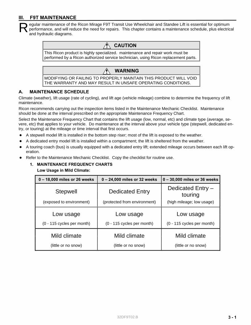
1. MAINTENANCE FREQUENCY CHARTS Low Usage in Mild Climate:
0 – 18,000 miles or 26 weeks 0 – 24,000 miles or 32 weeks 0 – 30,000 miles or 36 weeks
Stepwell Dedicated Entry Dedicated Entry – touring
(exposed to environment) (protected from environment) (high mileage; low usage)
Low usage Low usage Low usage (0 - 115 cycles per month) (0 - 115 cycles per month) (0 - 115 cycles per month)
Mild climate Mild climate Mild climate (little or no snow) (little or no snow) (little or no snow)
R

32DF9T02.B 3 - 2
Low to Normal Usage in Mild to Average Climate:
0 – 18,000 miles or 22 weeks 0 – 24,000 miles or 28 weeks 0 – 30,000 or 32 weeks
Stepwell Dedicated Entry Dedicated Entry – touring
(exposed to environment) (protected from environment) (high mileage; low usage)
Low Normal usage
Low Normal usage
Low Normal usage
(0 – 115 cycles)
(116 – 230 cycles per month)
(0 – 115 cycles)
(116 – 230 cycles per month)
(0 – 115 cycles)
(116 – 230 cycles per month)
Mild Average climate
Mild Average climate
Mild Average climate
(little or no snow)
(light snow) (light snow) (light snow) (little or no snow)
(light snow)
Low to High Usage in Severe Climate:
0 – 6,000 miles or 6 weeks 0 – 12,000 miles or 6 weeks 0 – 18,000 miles or 6 weeks
Stepwell Dedicated Entry Dedicated Entry – touring
(exposed to environment) (protected from environment) (high mileage; low usage)
Low, normal, and high usage
Low, normal, and high usage
Low, normal, and high usage
(0 – 230+ cycles per month) (0 – 230+ cycles per month) (0 – 230+ cycles per month)
Severe climate Severe climate Severe climate (medium to heavy snow /
marine) (medium to heavy snow /
marine) (medium to heavy snow /
marine)
32DF9T02.B 3 - 3
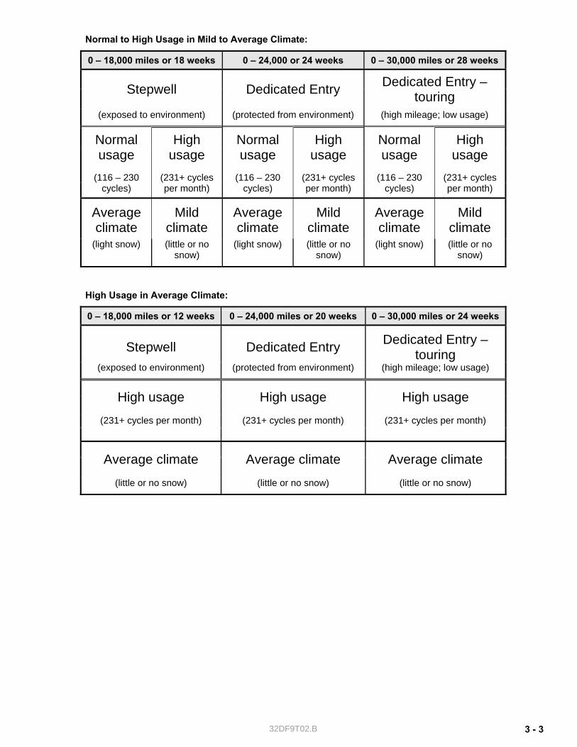
Normal to High Usage in Mild to Average Climate:
0 – 18,000 miles or 18 weeks 0 – 24,000 or 24 weeks 0 – 30,000 miles or 28 weeks
Stepwell Dedicated Entry Dedicated Entry – touring
(exposed to environment) (protected from environment) (high mileage; low usage)
Normal usage
High usage
Normal usage
High usage
Normal usage
High usage
(116 – 230 cycles)
(231+ cycles per month)
(116 – 230 cycles)
(231+ cycles per month)
(116 – 230 cycles)
(231+ cyclesper month)
Average climate
Mild climate
Average climate
Mild climate
Average climate
Mild climate
(light snow) (little or no snow)
(light snow) (little or no snow)
(light snow) (little or no snow)
High Usage in Average Climate:
0 – 18,000 miles or 12 weeks 0 – 24,000 miles or 20 weeks 0 – 30,000 miles or 24 weeks
Stepwell Dedicated Entry Dedicated Entry – touring
(exposed to environment) (protected from environment) (high mileage; low usage)
High usage High usage High usage
(231+ cycles per month) (231+ cycles per month) (231+ cycles per month)
Average climate Average climate Average climate
(little or no snow) (little or no snow) (little or no snow)
32DF9T02.B 3 - 4
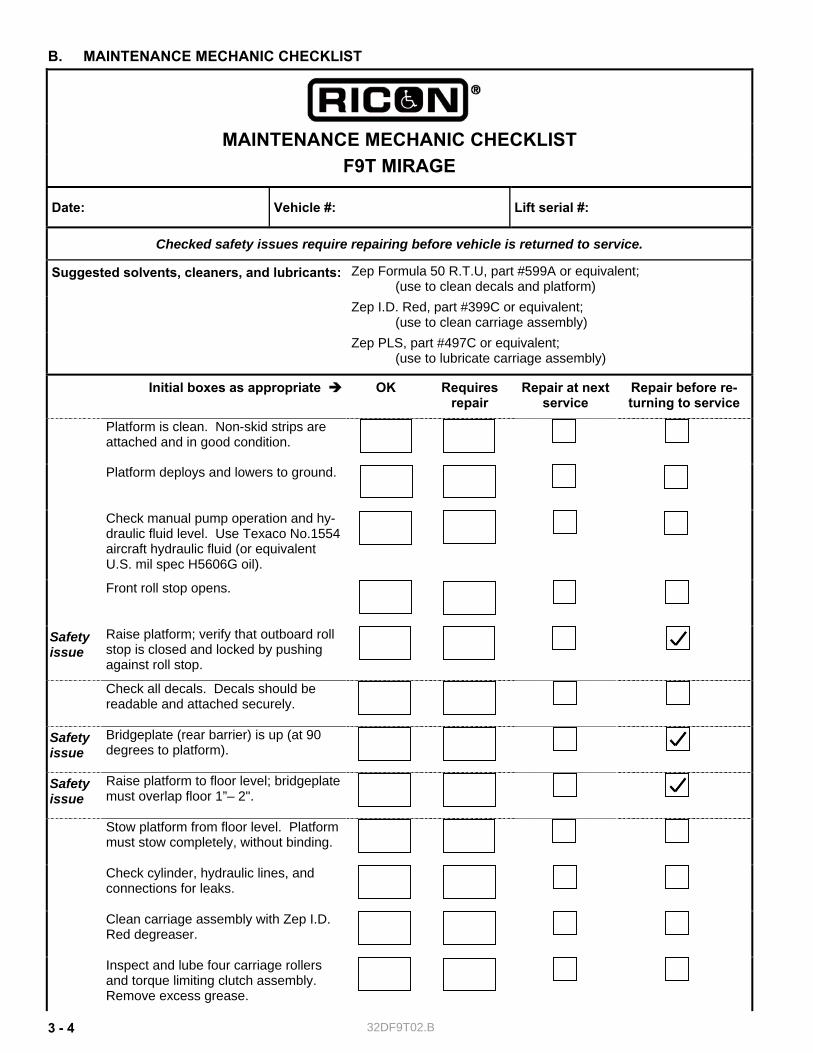
B. MAINTENANCE MECHANIC CHECKLIST
MAINTENANCE MECHANIC CHECKLIST F9T MIRAGE
Date: Vehicle #: Lift serial #:
Checked safety issues require repairing before vehicle is returned to service.
Zep Formula 50 R.T.U, part #599A or equivalent; (use to clean decals and platform) Zep I.D. Red, part #399C or equivalent; (use to clean carriage assembly)
Suggested solvents, cleaners, and lubricants:
Zep PLS, part #497C or equivalent; (use to lubricate carriage assembly)
Initial boxes as appropriate OK Requires repair
Repair at next service
Repair before re-turning to service
Platform is clean. Non-skid strips are attached and in good condition.
Platform deploys and lowers to ground.
Check manual pump operation and hy-draulic fluid level. Use Texaco No.1554 aircraft hydraulic fluid (or equivalent U.S. mil spec H5606G oil).
Front roll stop opens.
Safety issue
Raise platform; verify that outboard roll stop is closed and locked by pushing against roll stop.
Check all decals. Decals should be readable and attached securely.
Safety issue
Bridgeplate (rear barrier) is up (at 90 degrees to platform).
Safety issue
Raise platform to floor level; bridgeplate must overlap floor 1”– 2".
Stow platform from floor level. Platform must stow completely, without binding.
Check cylinder, hydraulic lines, and connections for leaks.
Clean carriage assembly with Zep I.D. Red degreaser.
Inspect and lube four carriage rollers and torque limiting clutch assembly. Remove excess grease.
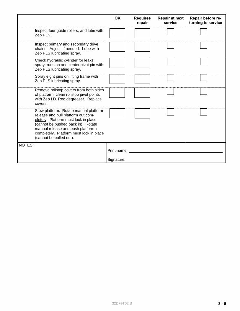
32DF9T02.B 3 - 5
OK Requires repair
Repair at next service
Repair before re-turning to service
Inspect four guide rollers, and lube with Zep PLS.
Inspect primary and secondary drive chains. Adjust, if needed. Lube with Zep PLS lubricating spray.
Check hydraulic cylinder for leaks; spray trunnion and center pivot pin with Zep PLS lubricating spray.
Spray eight pins on lifting frame with Zep PLS lubricating spray.
Remove rollstop covers from both sides of platform; clean rollstop pivot points with Zep I.D. Red degreaser. Replace covers.
Stow platform. Rotate manual platform release and pull platform out com-pletely. Platform must lock in place (cannot be pushed back in). Rotate manual release and push platform in completely. Platform must lock in place (cannot be pulled out).
NOTES: Print name: Signature:
32DF9T02.B 3 - 6
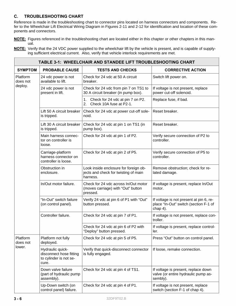
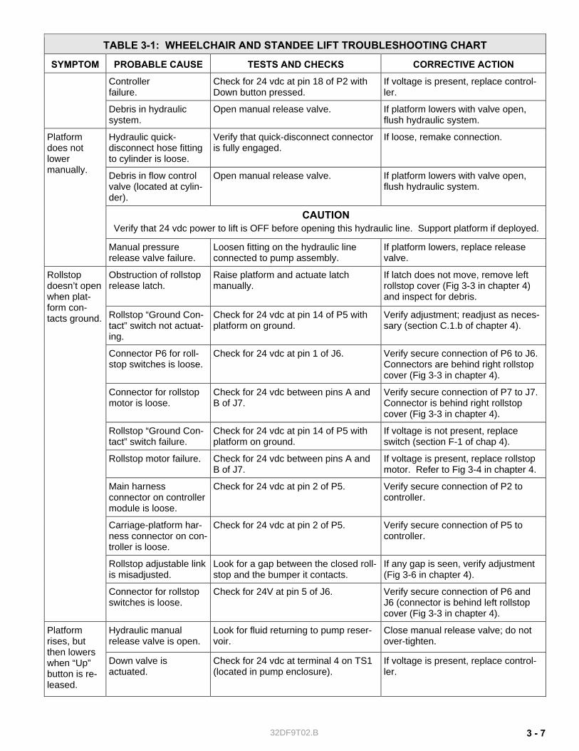
C. TROUBLESHOOTING CHART Reference is made in the troubleshooting chart to connector pins located on harness connectors and components. Re-fer to the Wheelchair Lift Electrical Wiring Diagram in Figures 2-11 and 2-12 for identification and location of these com-ponents and connectors.
NOTE: Figures referenced in the troubleshooting chart are located either in this chapter or other chapters in this man-ual.
NOTE: Verify that the 24 VDC power supplied to the wheelchair lift by the vehicle is present, and is capable of supply-ing sufficient electrical current. Also, verify that vehicle interlock requirements are met.
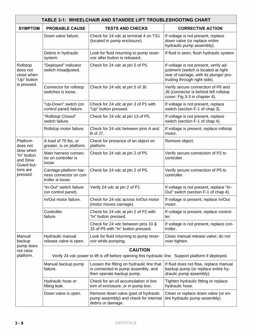
TABLE 3-1: WHEELCHAIR AND STANDEE LIFT TROUBLESHOOTING CHART
SYMPTOM PROBABLE CAUSE TESTS AND CHECKS CORRECTIVE ACTION
24 vdc power is not available to lift.
Check for 24 vdc at 50 A circuit breaker.
Switch lift power on.
Check for 24 vdc from pin 7 on TS1 to 30 A circuit breaker (in pump box).
If voltage is not present, replace power cut-off solenoid.
24 vdc power is not present in lift.
1. Check for 24 vdc at pin 7 on P2. 2. Check 10A fuse at P2-1.
Replace fuse, if bad.
Lift 50 A circuit breaker is tripped.
Check for 24 vdc at power cut-off sole-noid.
Reset breaker.
Lift 30 A circuit breaker is tripped.
Check for 24 vdc at pin 1 on TS1 (in pump box).
Reset breaker.
Platform does not deploy.
Main harness connec-tor on controller is loose.
Check for 24 vdc at pin 1 of P2. Verify secure connection of P2 to controller.
Carriage-platform harness connector on controller is loose.
Check for 24 vdc at pin 2 of P5. Verify secure connection of P5 to controller.
Obstruction in enclosure.
Look inside enclosure for foreign ob-jects and check for twisting of main harness.
Remove obstruction; check for re-lated damage.
In/Out motor failure. Check for 24 vdc across In/Out motor (moves carriage) with “Out” button pressed.
If voltage is present, replace In/Out motor.
“In-Out” switch failure (on control panel).
Verify 24 vdc at pin 6 of P1 with “Out” button pressed.
If voltage is not present at pin 6, re-place “In-Out” switch (section F-1 of chap 4).
Check for 24 vdc at pin 7 of P1. If voltage is not present, replace con-troller.
Controller failure.
Check for 24 vdc at pin 6 of P2 with “Deploy” button pressed.
If voltage is present, replace control-ler.
Platform not fully deployed.
Check for 24 vdc at pin 5 of P5. Press “Out” button on control panel.
Hydraulic quick-disconnect hose fitting to cylinder is not se-cure.
Verify that quick-disconnect connector is fully engaged.
If loose, remake connection.
Down valve failure (part of hydraulic pump assembly).
Check for 24 vdc at pin 4 of TS1. If voltage is present, replace down valve (or entire hydraulic pump as-sembly).
Platform does not lower.
Up-Down switch (on control panel) failure.
Check for 24 vdc at pin 4 of P1. If voltage is not present, replace switch (section F-1 of chap 4).
32DF9T02.B 3 - 7
TABLE 3-1: WHEELCHAIR AND STANDEE LIFT TROUBLESHOOTING CHART
SYMPTOM PROBABLE CAUSE TESTS AND CHECKS CORRECTIVE ACTION
Controller failure.
Check for 24 vdc at pin 18 of P2 with Down button pressed.
If voltage is present, replace control-ler.
Debris in hydraulic system.
Open manual release valve. If platform lowers with valve open, flush hydraulic system.
Hydraulic quick-disconnect hose fitting to cylinder is loose.
Verify that quick-disconnect connector is fully engaged.
If loose, remake connection.
Debris in flow control valve (located at cylin-der).
Open manual release valve. If platform lowers with valve open, flush hydraulic system.
CAUTION Verify that 24 vdc power to lift is OFF before opening this hydraulic line. Support platform if deployed.
Platform does not lower manually.
Manual pressure release valve failure.
Loosen fitting on the hydraulic line connected to pump assembly.
If platform lowers, replace release valve.
Obstruction of rollstop release latch.
Raise platform and actuate latch manually.
If latch does not move, remove left rollstop cover (Fig 3-3 in chapter 4) and inspect for debris.
Rollstop “Ground Con-tact” switch not actuat-ing.
Check for 24 vdc at pin 14 of P5 with platform on ground.
Verify adjustment; readjust as neces-sary (section C.1.b of chapter 4).
Connector P6 for roll-stop switches is loose.
Check for 24 vdc at pin 1 of J6. Verify secure connection of P6 to J6. Connectors are behind right rollstop cover (Fig 3-3 in chapter 4).
Connector for rollstop motor is loose.
Check for 24 vdc between pins A and B of J7.
Verify secure connection of P7 to J7. Connector is behind right rollstop cover (Fig 3-3 in chapter 4).
Rollstop “Ground Con-tact” switch failure.
Check for 24 vdc at pin 14 of P5 with platform on ground.
If voltage is not present, replace switch (section F-1 of chap 4).
Rollstop motor failure. Check for 24 vdc between pins A and B of J7.
If voltage is present, replace rollstop motor. Refer to Fig 3-4 in chapter 4.
Main harness connector on controller module is loose.
Check for 24 vdc at pin 2 of P5. Verify secure connection of P2 to controller.
Carriage-platform har-ness connector on con-troller is loose.
Check for 24 vdc at pin 2 of P5. Verify secure connection of P5 to controller.
Rollstop adjustable link is misadjusted.
Look for a gap between the closed roll-stop and the bumper it contacts.
If any gap is seen, verify adjustment (Fig 3-6 in chapter 4).
Rollstop doesn’t open when plat-form con-tacts ground.
Connector for rollstop switches is loose.
Check for 24V at pin 5 of J6. Verify secure connection of P6 and J6 (connector is behind left rollstop cover (Fig 3-3 in chapter 4).
Hydraulic manual release valve is open.
Look for fluid returning to pump reser-voir.
Close manual release valve; do not over-tighten.
Platform rises, but then lowers when “Up” button is re-leased.
Down valve is actuated.
Check for 24 vdc at terminal 4 on TS1 (located in pump enclosure).
If voltage is present, replace control-ler.
32DF9T02.B 3 - 8
TABLE 3-1: WHEELCHAIR AND STANDEE LIFT TROUBLESHOOTING CHART
SYMPTOM PROBABLE CAUSE TESTS AND CHECKS CORRECTIVE ACTION
Down valve failure. Check for 24 vdc at terminal 4 on TS1 (located in pump enclosure).
If voltage is not present, replace down valve (or replace entire hydraulic pump assembly).
Debris in hydraulic system.
Look for fluid returning to pump reser-voir after button is released.
If fluid is seen, flush hydraulic system.
“Deployed” indicator switch misadjusted.
Check for 24 vdc at pin 5 of P5. If voltage is not present, verify ad-justment (switch is located at right rear of carriage, with its plunger pro-truding through right side).
Connector for rollstop switches is loose.
Check for 24 vdc at pin 5 of J6. Verify secure connection of P6 and J6 (connector is behind left rollstop cover; Fig 3-3 in chapter 4).
“Up-Down” switch (on control panel) failure.
Check for 24 vdc at pin 3 of P1 with “Up” button pressed.
If voltage is not present, replace switch (section F-1 of chap 3).
“Rollstop Closed” switch failure.
Check for 24 vdc at pin 13 of P5. If voltage is not present, replace switch (section F-1 of chap 4).
Rollstop does not close when “Up” button is pressed.
Rollstop motor failure. Check for 24 vdc between pins A and B of J7.
If voltage is present, replace rollstop motor.
A load of 75 lbs, or greater, is on platform.
Check for presence of an object on platform.
Remove object.
Main harness connec-tor on controller is loose.
Check for 24 vdc at pin 2 of P5. Verify secure connection of P2 to controller.
Carriage-platform har-ness connector on con-troller is loose.
Check for 24 vdc at pin 2 of P5. Verify secure connection of P5 to controller.
“In-Out” switch failure (on control panel).
Verify 24 vdc at pin 2 of P1.
If voltage is not present, replace “In-Out” switch (section F-1 of chap 4).
In/Out motor failure. Check for 24 vdc across In/Out motor (motor moves carriage).
If voltage is present, replace In/Out motor.
Check for 24 vdc at pin 2 of P2 with “In” button pressed.
If voltage is present, replace control-ler.
Platform does not stow when “In” button and Stow Guard but-tons are pressed.
Controller failure.
Check for 24 vdc between pins 10 & 15 of P5 with “In” button pressed.
If voltage is not present, replace con-troller.
Hydraulic manual release valve is open.
Look for fluid returning to pump reser-voir while pumping.
Close manual release valve; do not over-tighten.
CAUTION Verify 24 vdc power to lift is off before opening this hydraulic line. Support platform if deployed.
Manual backup pump failure.
Loosen the fitting on hydraulic line that is connected to pump assembly, and then operate backup pump.
If fluid does not flow, replace manual backup pump (or replace entire hy-draulic pump assembly).
Hydraulic hose or fitting leak.
Check for an oil accumulation in bot-tom of enclosure, or in pump box.
Tighten hydraulic fitting or replace hydraulic hose.
Manual backup pump does not raise platform.
Down valve is open.
Remove down valve (part of hydraulic pump assembly) and check for internal debris or damage.
Clean or replace down valve (or en-tire hydraulic pump assembly).
32DF9T02.B 3 - 9
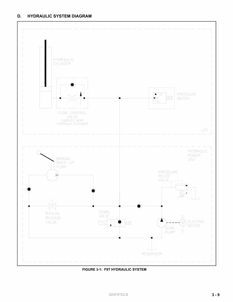
D. HYDRAULIC SYSTEM DIAGRAM
FIGURE 3-1: F9T HYDRAULIC SYSTEM
32DF9T02.B 3 - 10
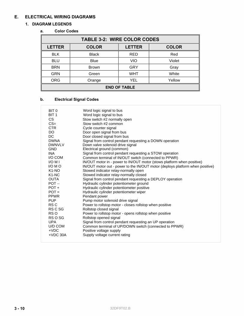
E. ELECTRICAL WIRING DIAGRAMS 1. DIAGRAM LEGENDS
a. Color Codes
TABLE 3-2: WIRE COLOR CODES LETTER COLOR LETTER COLOR
BLK Black RED Red BLU Blue VIO Violet BRN Brown GRY Gray GRN Green WHT White ORG Orange YEL Yellow
END OF TABLE
b. Electrical Signal Codes
Down valve solenoid drive signal
IN/OUT motor in - power to IN/OUT motor (stows platform when positive)Common terminal of IN/OUT switch (connected to PPWR)Signal from control pendant requesting a STOW operation
Pump motor solenoid drive signalPower to rollstop motor - closes rollstop when positive
Power to rollstop motor - opens rollstop when positive
Supply voltage current rating
Signal from control pendant requesting a DEPLOY operation
Rollstop closed signal
Rollstop opened signalSignal from control pendant requesting an UP operation
Pendant power
Positive voltage supply
IN/OUT motor out - power to the IN/OUT motor (deploys platform when positive)
+VDC 30A
UPA
+VDC
RS C SGRS O
RS C
RS O SG
I/O M O
OUTA
PUPPPWR
I/O M II/O COMINA
Signal from control pendant requesting a DOWN operation
Cycle counter signal
Stow switch #2 normally openStow switch #2 common
Word logic signal to busWord logic signal to bus
Door open signal from busDoor closed signal from bus
CS
CTRCS=
DWNADWNVLV
DODC
BIT 0BIT 1
K1-NCK1-NO Stowed indicator relay-normally open
Stowed indicator relay-normally closed
POT POT +POT =
Hydraulic cylinder potentiometer groundHydraulic cylinder potentiometer positiveHydraulic cylinder potentiometer wiper
U/D COM Common terminal of UP/DOWN switch (connected to PPWR)
¯
GND Electrical ground (common)
32DF9T02.B 3 - 11
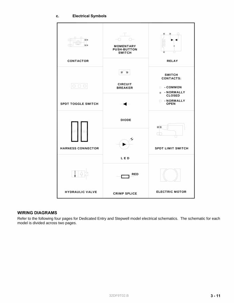
c. Electrical Symbols
WIRING DIAGRAMS Refer to the following four pages for Dedicated Entry and Stepwell model electrical schematics. The schematic for each model is divided across two pages.
RELAY
PUSH-BUTTONMOMENTARY
SPDT LIMIT SWITCH
SWITCH
CIRCUIT
L E D
OPEN
- NORMALLY
- NORMALLY CLOSED
DIODE
SWITCH
- COMMON
CONTACTS:
CONTACTOR
SPDT TOGGLE SWITCH
BREAKER
HARNESS CONNECTOR
HYDRAULIC VALVE CRIMP SPLICE ELECTRIC MOTOR
RED
32DF9T02.B 3 - 12
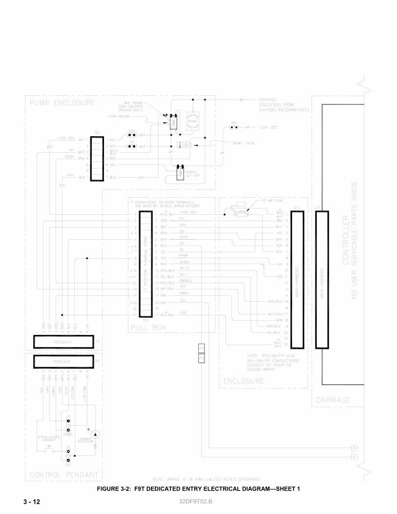
FIGURE 3-2: F9T DEDICATED ENTRY ELECTRICAL DIAGRAM—SHEET 1

32DF9T02.B 3 - 13
FIGURE 3-3: F9T DEDICATED ENTRY ELECTRICAL DIAGRAM—SHEET 2

32DF9T02.B 3 - 14
FIGURE 3-4: F9T STEPWELL ELECTRICAL DIAGRAM—SHEET 1
32DF9T02.B 3 - 15
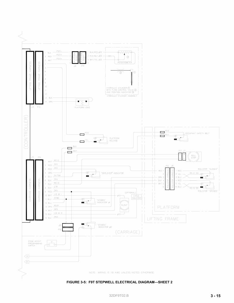
FIGURE 3-5: F9T STEPWELL ELECTRICAL DIAGRAM—SHEET 2

32DF9T02.B 3 - 16
This page intentionally left blank.
-GO TO NEXT CHAPTER- -RETURN TO PREVIOUS CHAPTER-
32DF9T02.C 4 - 1
IV. F9T MAJOR COMPONENT SERVICE his chapter provides instructions for major system repairs, system adjustments, and parts replacement on the RICON Mirage F9T Series Transit Use Wheelchair and Standee Lift. Maintain the lift at its highest level of performance by doing the required maintenance. Ricon recommends
a thorough inspection every six months. Nearly all illustrations in this chapter apply to both Dedicated Entry and Stepwell models. As a result,
some illustrations may differ slightly from what is being worked on. A specific repair task might not require completion of all listed steps in a procedure. Additional component illustrations are available in the Spare Parts chapter.
A. GENERAL SAFETY PRECAUTIONS
WARNING! THIS RICON PRODUCT IS HIGHLY SPECIALIZED. AN AUTHORIZED RICON SERVICE TECHNICIAN MUST PERFORM MAINTENANCE AND REPAIRS USING RICON REPLACE-MENT PARTS. MODIFYING OR NOT PROPERLY MAINTAINING THIS PRODUCT WILL VOID THE WARRANTY, AND MAY RESULT IN UNSAFE OPERATING CONDITIONS.
The following general safety precautions must be followed during service and maintenance: Do not attempt maintenance, repairs, or adjustments without the presence of a person capable of
rendering first-aid. Take notice of all injuries, regardless of how slight. Administer first aid or seek medical attention im-
mediately. Wear protective eye shields and appropriate clothing at all times. Work in a properly ventilated area. Do not smoke, or use an open flame, near the battery. Exercise caution when operating lift to avoid injury. Be certain that hands, feet, legs and clothing are
not in path of the platform as it moves. Be cautious when using metallic (conductive) tools near the battery, or heavy gauge wires. If battery acid contacts skin, wash area immediately with soap and water. Check under vehicle before drilling or cutting to avoid damage to the frame, subframe members, wir-
ing, hydraulic lines, etc. Thoroughly understand the operating instructions before attempting to operate lift. Keep others clear during lift operation.
T
32DF9T02.C 4 - 2
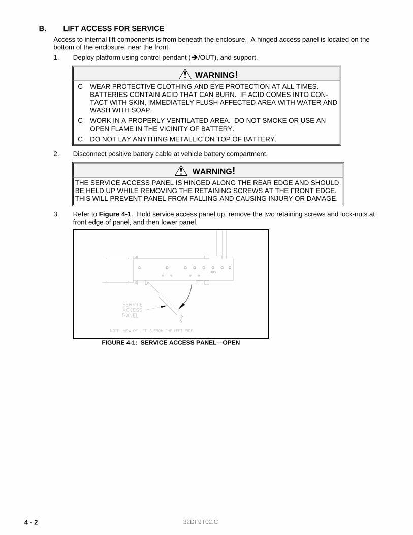
B. LIFT ACCESS FOR SERVICE Access to internal lift components is from beneath the enclosure. A hinged access panel is located on the bottom of the enclosure, near the front. 1. Deploy platform using control pendant ( /OUT), and support.
WARNING! C WEAR PROTECTIVE CLOTHING AND EYE PROTECTION AT ALL TIMES.
BATTERIES CONTAIN ACID THAT CAN BURN. IF ACID COMES INTO CON-TACT WITH SKIN, IMMEDIATELY FLUSH AFFECTED AREA WITH WATER AND WASH WITH SOAP.
C WORK IN A PROPERLY VENTILATED AREA. DO NOT SMOKE OR USE AN OPEN FLAME IN THE VICINITY OF BATTERY.
C DO NOT LAY ANYTHING METALLIC ON TOP OF BATTERY.
2. Disconnect positive battery cable at vehicle battery compartment.
WARNING! THE SERVICE ACCESS PANEL IS HINGED ALONG THE REAR EDGE AND SHOULD BE HELD UP WHILE REMOVING THE RETAINING SCREWS AT THE FRONT EDGE. THIS WILL PREVENT PANEL FROM FALLING AND CAUSING INJURY OR DAMAGE.
3. Refer to Figure 4-1. Hold service access panel up, remove the two retaining screws and lock-nuts at front edge of panel, and then lower panel.
FIGURE 4-1: SERVICE ACCESS PANEL—OPEN
32DF9T02.C 4 - 3
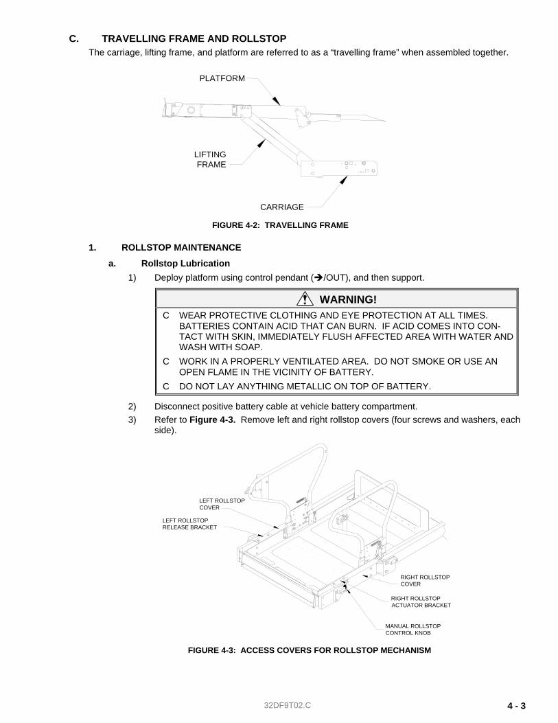
C. TRAVELLING FRAME AND ROLLSTOP The carriage, lifting frame, and platform are referred to as a “travelling frame” when assembled together.
1. ROLLSTOP MAINTENANCE
a. Rollstop Lubrication 1) Deploy platform using control pendant ( /OUT), and then support.
WARNING! C WEAR PROTECTIVE CLOTHING AND EYE PROTECTION AT ALL TIMES.
BATTERIES CONTAIN ACID THAT CAN BURN. IF ACID COMES INTO CON-TACT WITH SKIN, IMMEDIATELY FLUSH AFFECTED AREA WITH WATER AND WASH WITH SOAP.
C WORK IN A PROPERLY VENTILATED AREA. DO NOT SMOKE OR USE AN OPEN FLAME IN THE VICINITY OF BATTERY.
C DO NOT LAY ANYTHING METALLIC ON TOP OF BATTERY.
2) Disconnect positive battery cable at vehicle battery compartment. 3) Refer to Figure 4-3. Remove left and right rollstop covers (four screws and washers, each
side).
LEFT ROLLSTOPCOVER
LEFT ROLLSTOPRELEASE BRACKET
MANUAL ROLLSTOPCONTROL KNOB
RIGHT ROLLSTOPACTUATOR BRACKET
RIGHT ROLLSTOPCOVER
FIGURE 4-3: ACCESS COVERS FOR ROLLSTOP MECHANISM
PLATFORM
CARRIAGE
LIFTINGFRAME
FIGURE 4-2: TRAVELLING FRAME
32DF9T02.C 4 - 4
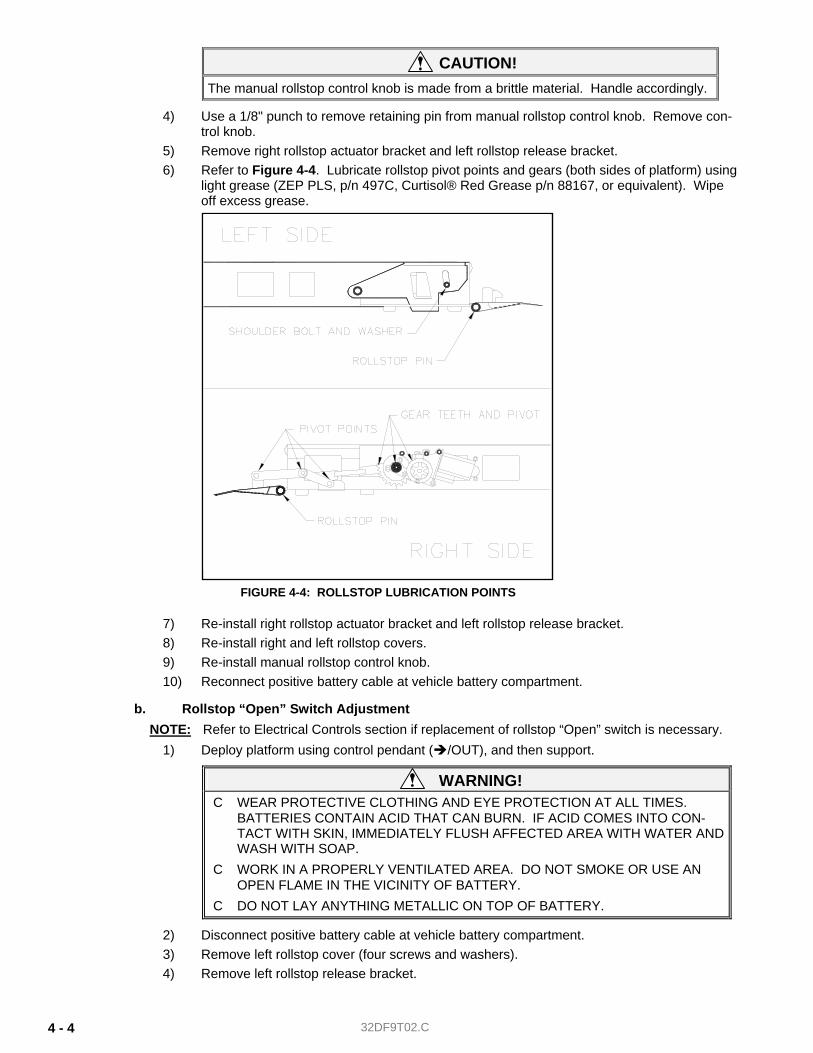
CAUTION! The manual rollstop control knob is made from a brittle material. Handle accordingly.
4) Use a 1/8" punch to remove retaining pin from manual rollstop control knob. Remove con-trol knob.
5) Remove right rollstop actuator bracket and left rollstop release bracket. 6) Refer to Figure 4-4. Lubricate rollstop pivot points and gears (both sides of platform) using
light grease (ZEP PLS, p/n 497C, Curtisol® Red Grease p/n 88167, or equivalent). Wipe off excess grease.
7) Re-install right rollstop actuator bracket and left rollstop release bracket. 8) Re-install right and left rollstop covers. 9) Re-install manual rollstop control knob. 10) Reconnect positive battery cable at vehicle battery compartment.
b. Rollstop “Open” Switch Adjustment NOTE: Refer to Electrical Controls section if replacement of rollstop “Open” switch is necessary.
1) Deploy platform using control pendant ( /OUT), and then support.
WARNING! C WEAR PROTECTIVE CLOTHING AND EYE PROTECTION AT ALL TIMES.
BATTERIES CONTAIN ACID THAT CAN BURN. IF ACID COMES INTO CON-TACT WITH SKIN, IMMEDIATELY FLUSH AFFECTED AREA WITH WATER AND WASH WITH SOAP.
C WORK IN A PROPERLY VENTILATED AREA. DO NOT SMOKE OR USE AN OPEN FLAME IN THE VICINITY OF BATTERY.
C DO NOT LAY ANYTHING METALLIC ON TOP OF BATTERY.
2) Disconnect positive battery cable at vehicle battery compartment. 3) Remove left rollstop cover (four screws and washers). 4) Remove left rollstop release bracket.
FIGURE 4-4: ROLLSTOP LUBRICATION POINTS
32DF9T02.C 4 - 5
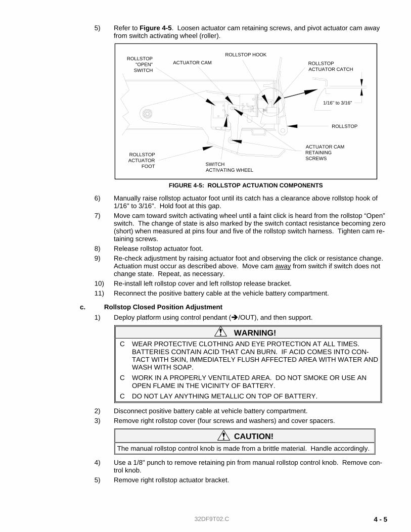
5) Refer to Figure 4-5. Loosen actuator cam retaining screws, and pivot actuator cam away from switch activating wheel (roller).
6) Manually raise rollstop actuator foot until its catch has a clearance above rollstop hook of 1/16" to 3/16". Hold foot at this gap.
7) Move cam toward switch activating wheel until a faint click is heard from the rollstop “Open” switch. The change of state is also marked by the switch contact resistance becoming zero (short) when measured at pins four and five of the rollstop switch harness. Tighten cam re-taining screws.
8) Release rollstop actuator foot. 9) Re-check adjustment by raising actuator foot and observing the click or resistance change.
Actuation must occur as described above. Move cam away from switch if switch does not change state. Repeat, as necessary.
10) Re-install left rollstop cover and left rollstop release bracket. 11) Reconnect the positive battery cable at the vehicle battery compartment.
c. Rollstop Closed Position Adjustment 1) Deploy platform using control pendant ( /OUT), and then support.
WARNING! C WEAR PROTECTIVE CLOTHING AND EYE PROTECTION AT ALL TIMES.
BATTERIES CONTAIN ACID THAT CAN BURN. IF ACID COMES INTO CON-TACT WITH SKIN, IMMEDIATELY FLUSH AFFECTED AREA WITH WATER AND WASH WITH SOAP.
C WORK IN A PROPERLY VENTILATED AREA. DO NOT SMOKE OR USE AN OPEN FLAME IN THE VICINITY OF BATTERY.
C DO NOT LAY ANYTHING METALLIC ON TOP OF BATTERY.
2) Disconnect positive battery cable at vehicle battery compartment. 3) Remove right rollstop cover (four screws and washers) and cover spacers.
CAUTION! The manual rollstop control knob is made from a brittle material. Handle accordingly.
4) Use a 1/8" punch to remove retaining pin from manual rollstop control knob. Remove con-trol knob.
5) Remove right rollstop actuator bracket.
FIGURE 4-5: ROLLSTOP ACTUATION COMPONENTS
ROLLSTOP ACTUATOR CATCH
ROLLSTOP
ACTUATOR CAMRETAINING SCREWS
ACTUATOR CAM
SWITCH ACTIVATING WHEEL
ROLLSTOP HOOKROLLSTOP
"OPEN"SWITCH
ROLLSTOPACTUATOR
FOOT
1/16" to 3/16"
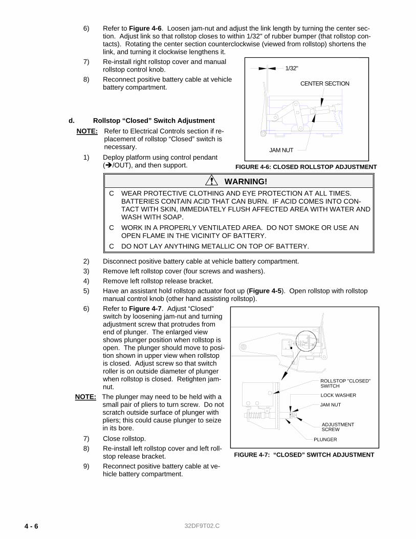
32DF9T02.C 4 - 6
6) Refer to Figure 4-6. Loosen jam-nut and adjust the link length by turning the center sec-tion. Adjust link so that rollstop closes to within 1/32" of rubber bumper (that rollstop con-tacts). Rotating the center section counterclockwise (viewed from rollstop) shortens the link, and turning it clockwise lengthens it.
7) Re-install right rollstop cover and manual rollstop control knob.
8) Reconnect positive battery cable at vehicle battery compartment.
d. Rollstop “Closed” Switch Adjustment NOTE: Refer to Electrical Controls section if re-
placement of rollstop “Closed” switch is necessary.
1) Deploy platform using control pendant ( /OUT), and then support.
WARNING! C WEAR PROTECTIVE CLOTHING AND EYE PROTECTION AT ALL TIMES.
BATTERIES CONTAIN ACID THAT CAN BURN. IF ACID COMES INTO CON-TACT WITH SKIN, IMMEDIATELY FLUSH AFFECTED AREA WITH WATER AND WASH WITH SOAP.
C WORK IN A PROPERLY VENTILATED AREA. DO NOT SMOKE OR USE AN OPEN FLAME IN THE VICINITY OF BATTERY.
C DO NOT LAY ANYTHING METALLIC ON TOP OF BATTERY.
2) Disconnect positive battery cable at vehicle battery compartment. 3) Remove left rollstop cover (four screws and washers). 4) Remove left rollstop release bracket. 5) Have an assistant hold rollstop actuator foot up (Figure 4-5). Open rollstop with rollstop
manual control knob (other hand assisting rollstop). 6) Refer to Figure 4-7. Adjust “Closed”
switch by loosening jam-nut and turning adjustment screw that protrudes from end of plunger. The enlarged view shows plunger position when rollstop is open. The plunger should move to posi-tion shown in upper view when rollstop is closed. Adjust screw so that switch roller is on outside diameter of plunger when rollstop is closed. Retighten jam-nut.
NOTE: The plunger may need to be held with a small pair of pliers to turn screw. Do not scratch outside surface of plunger with pliers; this could cause plunger to seize in its bore.
7) Close rollstop. 8) Re-install left rollstop cover and left roll-
stop release bracket. 9) Reconnect positive battery cable at ve-
hicle battery compartment.
FIGURE 4-6: CLOSED ROLLSTOP ADJUSTMENT
CENTER SECTION
JAM NUT
1/32"
FIGURE 4-7: “CLOSED” SWITCH ADJUSTMENT
JAM NUT
PLUNGER
ADJUSTMENT
ROLLSTOP "CLOSED"SWITCH
SCREW
LOCK WASHER
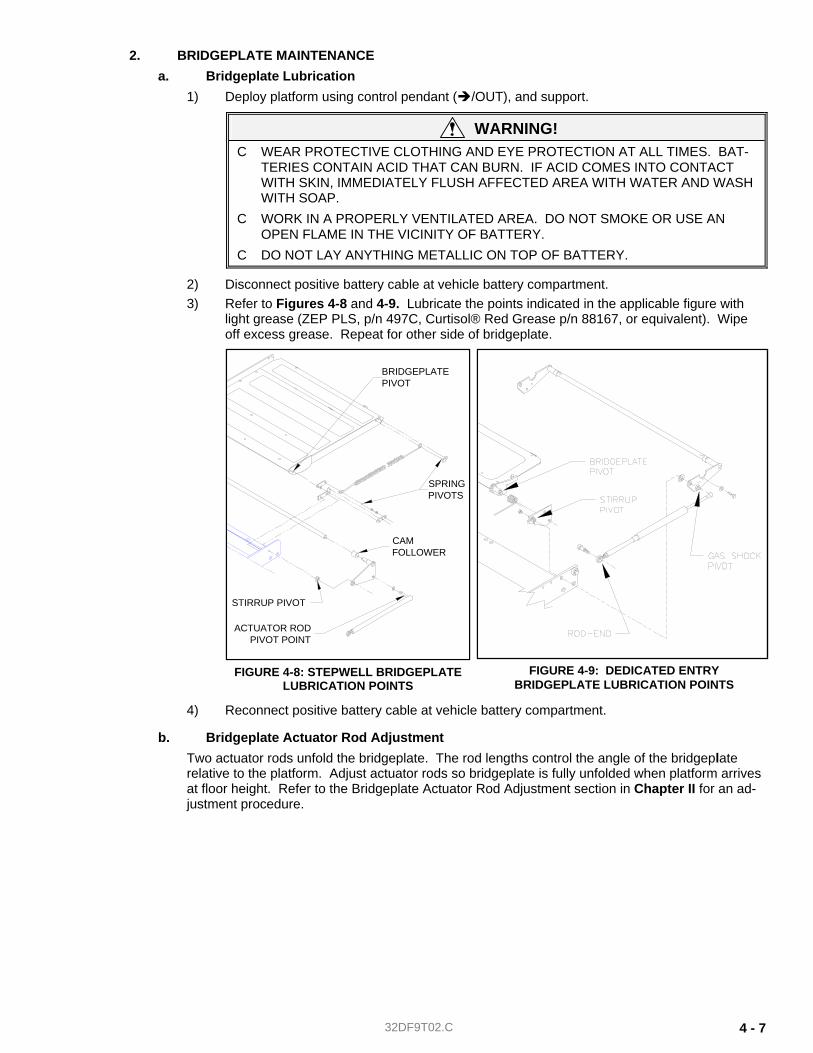
32DF9T02.C 4 - 7
2. BRIDGEPLATE MAINTENANCE a. Bridgeplate Lubrication
1) Deploy platform using control pendant ( /OUT), and support.
WARNING! C WEAR PROTECTIVE CLOTHING AND EYE PROTECTION AT ALL TIMES. BAT-
TERIES CONTAIN ACID THAT CAN BURN. IF ACID COMES INTO CONTACT WITH SKIN, IMMEDIATELY FLUSH AFFECTED AREA WITH WATER AND WASH WITH SOAP.
C WORK IN A PROPERLY VENTILATED AREA. DO NOT SMOKE OR USE AN OPEN FLAME IN THE VICINITY OF BATTERY.
C DO NOT LAY ANYTHING METALLIC ON TOP OF BATTERY.
2) Disconnect positive battery cable at vehicle battery compartment. 3) Refer to Figures 4-8 and 4-9. Lubricate the points indicated in the applicable figure with
light grease (ZEP PLS, p/n 497C, Curtisol® Red Grease p/n 88167, or equivalent). Wipe off excess grease. Repeat for other side of bridgeplate.
4) Reconnect positive battery cable at vehicle battery compartment.
b. Bridgeplate Actuator Rod Adjustment Two actuator rods unfold the bridgeplate. The rod lengths control the angle of the bridgeplate relative to the platform. Adjust actuator rods so bridgeplate is fully unfolded when platform arrives at floor height. Refer to the Bridgeplate Actuator Rod Adjustment section in Chapter II for an ad-justment procedure.
FIGURE 4-9: DEDICATED ENTRYBRIDGEPLATE LUBRICATION POINTS
FIGURE 4-8: STEPWELL BRIDGEPLATE LUBRICATION POINTS
BRIDGEPLATEPIVOT
SPRINGPIVOTS
CAMFOLLOWER
STIRRUP PIVOT
ACTUATOR RODPIVOT POINT
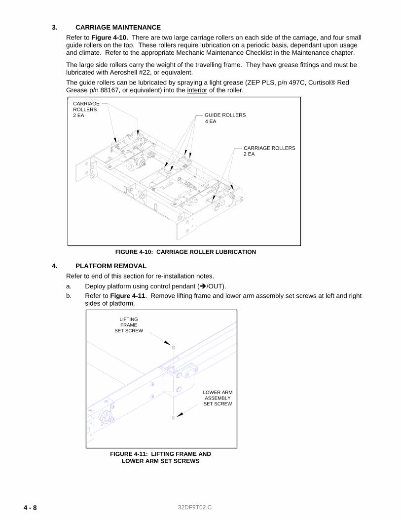
32DF9T02.C 4 - 8
3. CARRIAGE MAINTENANCE Refer to Figure 4-10. There are two large carriage rollers on each side of the carriage, and four small guide rollers on the top. These rollers require lubrication on a periodic basis, dependant upon usage and climate. Refer to the appropriate Mechanic Maintenance Checklist in the Maintenance chapter.
The large side rollers carry the weight of the travelling frame. They have grease fittings and must be lubricated with Aeroshell #22, or equivalent. The guide rollers can be lubricated by spraying a light grease (ZEP PLS, p/n 497C, Curtisol® Red Grease p/n 88167, or equivalent) into the interior of the roller.
4. PLATFORM REMOVAL Refer to end of this section for re-installation notes. a. Deploy platform using control pendant ( /OUT). b. Refer to Figure 4-11. Remove lifting frame and lower arm assembly set screws at left and right
sides of platform.
GUIDE ROLLERS
CARRIAGE ROLLERS2 EA
4 EA
CARRIAGEROLLERS2 EA
FIGURE 4-10: CARRIAGE ROLLER LUBRICATION
FIGURE 4-11: LIFTING FRAME AND LOWER ARM SET SCREWS
LIFTINGFRAME
SET SCREW
LOWER ARMASSEMBLY
SET SCREW

32DF9T02.C 4 - 9
c. Raise platform to vehicle floor height using control pendant ( /UP), and then support.
WARNING! C WEAR PROTECTIVE CLOTHING AND EYE PROTECTION AT ALL TIMES. BAT-
TERIES CONTAIN ACID THAT CAN BURN. IF ACID COMES INTO CONTACT WITH SKIN, IMMEDIATELY FLUSH AFFECTED AREA WITH WATER AND WASH WITH SOAP.
C WORK IN A PROPERLY VENTILATED AREA. DO NOT SMOKE OR USE AN OPEN FLAME IN THE VICINITY OF BATTERY.
C DO NOT LAY ANYTHING METALLIC ON TOP OF BATTERY.
d. Disconnect positive battery cable at vehicle battery compartment.
e. Refer to Figure 4-12. View A-A is from beneath platform. Locate right-side actuator rod assem-bly (right-hand side of platform, at top of lifting frame). Loosen rod-end jam-nut.
f. Remove shoulder bolt that fastens actuator rod-end to mounting plate (on lifting frame); catch spacer as it falls.
g. Repeat for left-side actuator rod assembly. h. Fold bridgeplate onto lift platform, and rotate actuator arms parallel to platform. Secure bridge-
plate and actuator arms to platform with cable ties. i. Remove right and left rollstop side covers (four screws and washers) and spacers. j. Disconnect electrical harnesses at both sides of platform (rollstop switch harness at left; rollstop
motor harness at right). Cut black and white leads to the safety belt switch; cut leads adjacent to factory-crimped butt splices. Remove cable ties that hold harnesses in place. Remove connec-tors from harnesses.
NOTE: Record connector pin position for each wire. This data will be used for platform re-installation; refer to wiring diagrams in Chapter 3. Crimp safety belt switch leads to harness with new butt splices when re-installing.
CAUTION! • Double-check platform support before removing lower mounting pins.
The platform will be free to rotate after pins are removed. • Do not damage outside surface of pins during removal. A pin should be
replaced if its outer surface is pitted or grooved after removal.
FIGURE 4-12: BRIDGEPLATE ACTUATOR ROD REMOVAL
SHOULDER BOLTJAM-NUT
SPACER
ACTUATOR
ASSEMBLYROD
VIEW A-A
VIEW A-ARIGHT-SIDE
MOUNTINGPLATE
LIFTINGFRAME
&
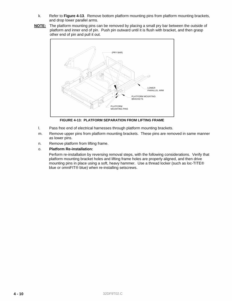
32DF9T02.C 4 - 10
k. Refer to Figure 4-13. Remove bottom platform mounting pins from platform mounting brackets, and drop lower parallel arms.
NOTE: The platform mounting pins can be removed by placing a small pry bar between the outside of platform and inner end of pin. Push pin outward until it is flush with bracket, and then grasp other end of pin and pull it out.
l. Pass free end of electrical harnesses through platform mounting brackets. m. Remove upper pins from platform mounting brackets. These pins are removed in same manner
as lower pins. n. Remove platform from lifting frame. o. Platform Re-installation:
Perform re-installation by reversing removal steps, with the following considerations. Verify that platform mounting bracket holes and lifting frame holes are properly aligned, and then drive mounting pins in place using a soft, heavy hammer. Use a thread locker (such as loc-TITE® blue or omniFIT® blue) when re-installing setscrews.
FIGURE 4-13: PLATFORM SEPARATION FROM LIFTING FRAME
PLATFORMMOUNTING PINS
PLATFORM MOUNTINGBRACKETS
LOWERPARALLEL ARM
(PRY BAR)
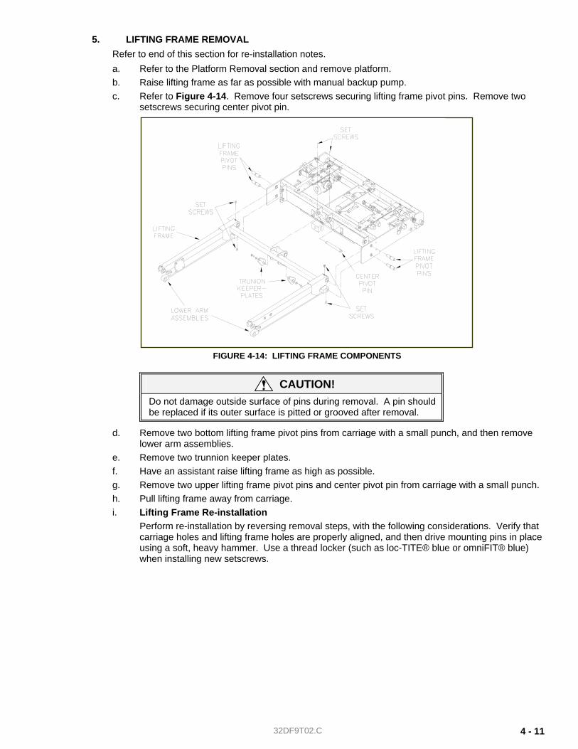
32DF9T02.C 4 - 11
5. LIFTING FRAME REMOVAL Refer to end of this section for re-installation notes. a. Refer to the Platform Removal section and remove platform. b. Raise lifting frame as far as possible with manual backup pump. c. Refer to Figure 4-14. Remove four setscrews securing lifting frame pivot pins. Remove two
setscrews securing center pivot pin.
CAUTION! Do not damage outside surface of pins during removal. A pin should be replaced if its outer surface is pitted or grooved after removal.
d. Remove two bottom lifting frame pivot pins from carriage with a small punch, and then remove lower arm assemblies.
e. Remove two trunnion keeper plates. f. Have an assistant raise lifting frame as high as possible. g. Remove two upper lifting frame pivot pins and center pivot pin from carriage with a small punch. h. Pull lifting frame away from carriage. i. Lifting Frame Re-installation
Perform re-installation by reversing removal steps, with the following considerations. Verify that carriage holes and lifting frame holes are properly aligned, and then drive mounting pins in place using a soft, heavy hammer. Use a thread locker (such as loc-TITE® blue or omniFIT® blue) when installing new setscrews.
FIGURE 4-14: LIFTING FRAME COMPONENTS
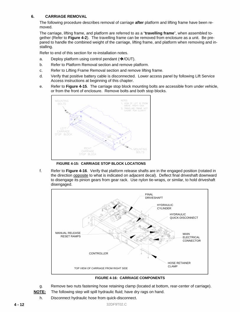
32DF9T02.C 4 - 12
6. CARRIAGE REMOVAL The following procedure describes removal of carriage after platform and lifting frame have been re-moved. The carriage, lifting frame, and platform are referred to as a “travelling frame”, when assembled to-gether (Refer to Figure 4-2). The travelling frame can be removed from enclosure as a unit. Be pre-pared to handle the combined weight of the carriage, lifting frame, and platform when removing and in-stalling. Refer to end of this section for re-installation notes. a. Deploy platform using control pendant ( /OUT). b. Refer to Platform Removal section and remove platform. c. Refer to Lifting Frame Removal section and remove lifting frame. d. Verify that positive battery cable is disconnected. Lower access panel by following Lift Service
Access instructions at beginning of this chapter. e. Refer to Figure 4-15. The carriage stop block mounting bolts are accessible from under vehicle,
or from the front of enclosure. Remove bolts and both stop blocks.
f. Refer to Figure 4-16. Verify that platform release shafts are in the engaged position (rotated in the direction opposite to what is indicated on adjacent decal). Deflect final driveshaft downward to disengage its pinion gears from gear rack. Use nylon tie-wraps, or similar, to hold driveshaft disengaged.
g. Remove two nuts fastening hose retaining clamp (located at bottom, rear-center of carriage). NOTE: The following step will spill hydraulic fluid; have dry rags on hand.
h. Disconnect hydraulic hose from quick-disconnect.
FIGURE 4-15: CARRIAGE STOP BLOCK LOCATIONS
FIGURE 4-16: CARRIAGE COMPONENTS
HYDRAULICQUICK-DISCONNECT
MAINELECTRICALCONNECTOR
HOSE RETAINER CLAMP
CONTROLLER
TOP VIEW OF CARRIAGE FROM RIGHT SIDE
HYDRAULICCYLINDER
FINALDRIVESHAFT
MANUAL RELEASERESET RAMPS
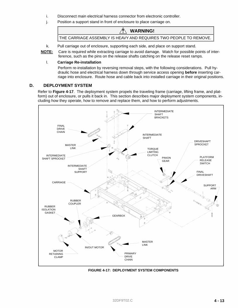
32DF9T02.C 4 - 13
i. Disconnect main electrical harness connector from electronic controller. j. Position a support stand in front of enclosure to place carriage on.
WARNING! THE CARRIAGE ASSEMBLY IS HEAVY AND REQUIRES TWO PEOPLE TO REMOVE.
k. Pull carriage out of enclosure, supporting each side, and place on support stand. NOTE: Care is required while extracting carriage to avoid damage. Watch for possible points of inter-
ference, such as the pins on the release shafts catching on the release reset ramps. l. Carriage Re-installation
Perform re-installation by reversing removal steps, with the following considerations. Pull hy-draulic hose and electrical harness down through service access opening before inserting car-riage into enclosure. Route hose and cable back into installed carriage in their original positions.
D. DEPLOYMENT SYSTEM Refer to Figure 4-17. The deployment system propels the traveling frame (carriage, lifting frame, and plat-form) out of enclosure, or pulls it back in. This section describes major deployment system components, in-cluding how they operate, how to remove and replace them, and how to perform adjustments.
FIGURE 4-17: DEPLOYMENT SYSTEM COMPONENTS
INTERMEDIATESHAFT
TORQUELIMITINGCLUTCH
FINALDRIVESHAFT
PINIONGEAR
MASTERLINK
PRIMARYDRIVECHAIN
IN/OUT MOTOR
RUBBERCOUPLER
RUBBERISOLATION
GASKET
INTERMEDIATESHAFT
SUPPORT
MASTERLINK
FINALDRIVECHAIN
GEARBOX
INTERMEDIATESHAFTBRACKETS
MOTORRETAINING
CLAMP
SUPPORTARM
PLATFORMRELEASESWITCH
CARRIAGE
DRIVESHAFTSPROCKET
INTERMEDIATESHAFT SPROCKET
32DF9T02.C 4 - 14
1. IN/OUT MOTOR AND GEARBOX The in/out motor drives the deployment system. The motor receives electric power from the on-board electronic controller; voltage polarity determines the direction of motor rotation (which determines whether platform is deployed or stowed). The motor drives the gearbox, reducing the motor speed and increasing torque. The gearbox drives the primary drive chain.
a. In/Out Motor and Gearbox Removal 1) Deploy platform using control pendant ( /OUT).
WARNING! THE SERVICE ACCESS PANEL IS HINGED ALONG THE REAR EDGE AND SHOULD BE HELD UP WHILE REMOVING THE RETAINING SCREWS AT THE FRONT EDGE. THIS WILL PREVENT PANEL FROM FALLING AND CAUSING INJURY OR DAMAGE.
2) Lower access panel by following Lift Service Access instructions at beginning of chapter. 3) Position primary drive chain master-link at bottom-center of its travel by moving carriage in
or out of enclosure. 4) Support platform.
WARNING! C WEAR PROTECTIVE CLOTHING AND EYE PROTECTION AT ALL TIMES. BAT-
TERIES CONTAIN ACID THAT CAN BURN. IF ACID COMES INTO CONTACT WITH SKIN, IMMEDIATELY FLUSH AFFECTED AREA WITH WATER AND WASH WITH SOAP.
C WORK IN A PROPERLY VENTILATED AREA. DO NOT SMOKE OR USE AN OPEN FLAME IN THE VICINITY OF BATTERY.
C DO NOT LAY ANYTHING METALLIC ON TOP OF BATTERY.
5) Disconnect positive battery cable at vehicle battery compartment. 6) Refer to Figure 4-17. Loosen two nuts fastening the gearbox to carriage. 7) Label motor electrical leads, and then disconnect. 8) Remove motor retaining clamp. 9) Slide gearmotor assembly toward platform. 10) Remove primary drive chain master link; remove chain. 11) Remove two nuts and washers fastening gearbox to carriage; support gearmotor assembly. 12) Remove rubber isolation gasket from gearmotor, and remove gearmotor assembly from car-
riage. 13) Remove nuts and washers fastening motor to gearbox. 14) Separate motor from gearbox; do not damage or lose rubber coupler.
NOTE: Refer to next section for re-installation.
b. In/Out Motor and Gearbox Installation 1) Refer to Figure 4-16. Slide rubber coupler onto gearbox input shaft. 2) Insert motor output shaft into coupler, and then align motor and gear box:
о Hold motor with electrical connections pointed at you, and positioned at 5 o’clock. о Hold gearbox with its output housing up. о Align motor studs with holes in gearbox flange and assemble.
3) Install star-washers and nuts on motor studs. 4) Place gearmotor assembly in carriage, with gearbox studs inserted in mounting tab slots. 5) Install lock washers and nuts on gear box studs. Do not tighten. 6) Install motor retaining clamp and vibration isolation gasket; the clamp fits over tab on gear-
motor support bracket. Do not tighten clamp. 7) Refer to PRIMARY DRIVE CHAIN INSTALLATION section. Install primary drive chain. 8) Reconnect two motor electrical leads.
32DF9T02.C 4 - 15
9) Raise service access panel, and install two retaining screws and lock-nuts at front edge of panel.
10) Reconnect positive battery cable at vehicle battery compartment.
2. DRIVE CHAINS The drive chains transfer power from gearmotor to final driveshaft. Power is transferred through pri-mary drive chain to torque limiting clutch (mounted on an intermediate shaft), and then to secondary drive chain.
a. Drive Chain Removal ♦ Final Drive Chain
1) Deploy platform using control pendant ( /OUT). 2) Raise platform to a comfortable working height and support.
WARNING! THE SERVICE ACCESS PANEL IS HINGED ALONG THE REAR EDGE AND SHOULD BE HELD UP WHILE REMOVING THE RETAINING SCREWS AT THE FRONT EDGE. THIS WILL PREVENT PANEL FROM FALLING AND CAUSING INJURY OR DAMAGE.
3) To gain access to underside of the lift, hold service access panel up, remove two retaining screws and lock-nuts from front edge of panel, and lower panel.
4) Refer to Figure 4-17. Position master link at bottom-center of its travel by moving carriage assembly forward or backward (use the DEPLOY and STOW functions).
WARNING! C WEAR PROTECTIVE CLOTHING AND EYE PROTECTION AT ALL TIMES. BAT-
TERIES CONTAIN ACID THAT CAN BURN. IF ACID COMES INTO CONTACT WITH SKIN, IMMEDIATELY FLUSH AFFECTED AREA WITH WATER AND WASH WITH SOAP.
C WORK IN A PROPERLY VENTILATED AREA. DO NOT SMOKE OR USE AN OPEN FLAME IN THE VICINITY OF BATTERY.
C DO NOT LAY ANYTHING METALLIC ON TOP OF BATTERY.
5) Disconnect positive battery cable at vehicle battery compartment. 6) Loosen two nuts fastening gearbox to the carriage. 7) Loosen two screws fastening intermediate shaft mounting bracket to carriage. The front
screw is accessible from top of lift, and rear screw is accessible through service hatch (use an open end wrench above intermediate shaft mounting bracket to hold nut).
8) Move gearmotor assembly toward driveshaft to slacken chain; a small pry bar can be in-serted between motor and front of carriage for leverage.
NOTE: DO NOT FORCE THE GEARMOTOR. Loosen two nuts further, or loosen motor retaining clamp to obtain more movement.
9) Remove master link and final drive chain.
♦ Primary Drive Chain 1) Fully deploy lift. 2) Raise platform to a comfortable working height and support.
WARNING! THE SERVICE ACCESS PANEL IS HINGED ALONG THE REAR EDGE AND SHOULD BE HELD UP WHILE REMOVING THE RETAINING SCREWS AT THE FRONT EDGE. THIS WILL PREVENT PANEL FROM FALLING AND CAUSING INJURY OR DAMAGE
3) To gain access to underside of lift, hold service access panel up, remove two retaining screws and lock-nuts from front edge of panel, and lower panel.
4) Refer to Figure 4-17. Position master link at bottom-center of its travel by moving carriage assembly forward or backward (use the DEPLOY and STOW functions).
32DF9T02.C 4 - 16
WARNING! C WEAR PROTECTIVE CLOTHING AND EYE PROTECTION AT ALL TIMES. BAT-
TERIES CONTAIN ACID THAT CAN BURN. IF ACID COMES INTO CONTACT WITH SKIN, IMMEDIATELY FLUSH AFFECTED AREA WITH WATER AND WASH WITH SOAP.
C WORK IN A PROPERLY VENTILATED AREA. DO NOT SMOKE OR USE AN OPEN FLAME IN THE VICINITY OF BATTERY.
C DO NOT LAY ANYTHING METALLIC ON TOP OF BATTERY.
5) Disconnect positive battery cable at vehicle battery compartment. 6) Loosen motor retaining clamp that fastens gearmotor to gearmotor support. 7) Loosen two nuts fastening gearbox to carriage. 8) Move gearmotor assembly toward driveshaft to slacken chain. A small pry bar may be in-
serted between motor and front of carriage to gain leverage. NOTE: DO NOT FORCE THE GEARMOTOR. Further loosen two nuts, or loosen motor retaining
clamp to obtain more movement. 9) Remove primary drive chain master link and primary drive chain.
b. DRIVE CHAIN INSTALLATION ♦ Final Drive Chain
1) Refer to Figure 4-17. Verify the two screws fastening the intermediate shaft mounting bracket to carriage are loose.
2) Install final drive chain around sprocket on final driveshaft, and around sprocket on interme-diate shaft. Install master link.
3) Refer to Final Drive Chain Adjustment section and adjust final drive chain.
♦ Primary Drive Chain 1) Refer to Figure 4-17. Loosen motor retaining clamp that fastens the gearmotor to gearmo-
tor support. 2) Loosen nuts fastening gearbox to carriage. 3) Install primary drive chain around sprocket on gearbox output shaft, and around clutch
sprocket. Install master link.
4) Refer to Primary Drive Chain Adjustment section and adjust primary drive chain.
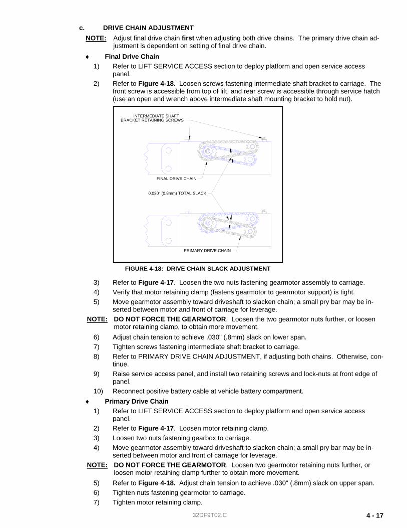
32DF9T02.C 4 - 17
c. DRIVE CHAIN ADJUSTMENT NOTE: Adjust final drive chain first when adjusting both drive chains. The primary drive chain ad-
justment is dependent on setting of final drive chain. ♦ Final Drive Chain
1) Refer to LIFT SERVICE ACCESS section to deploy platform and open service access panel.
2) Refer to Figure 4-18. Loosen screws fastening intermediate shaft bracket to carriage. The front screw is accessible from top of lift, and rear screw is accessible through service hatch (use an open end wrench above intermediate shaft mounting bracket to hold nut).
3) Refer to Figure 4-17. Loosen the two nuts fastening gearmotor assembly to carriage. 4) Verify that motor retaining clamp (fastens gearmotor to gearmotor support) is tight. 5) Move gearmotor assembly toward driveshaft to slacken chain; a small pry bar may be in-
serted between motor and front of carriage for leverage. NOTE: DO NOT FORCE THE GEARMOTOR. Loosen the two gearmotor nuts further, or loosen
motor retaining clamp, to obtain more movement. 6) Adjust chain tension to achieve .030" (.8mm) slack on lower span. 7) Tighten screws fastening intermediate shaft bracket to carriage. 8) Refer to PRIMARY DRIVE CHAIN ADJUSTMENT, if adjusting both chains. Otherwise, con-
tinue. 9) Raise service access panel, and install two retaining screws and lock-nuts at front edge of
panel. 10) Reconnect positive battery cable at vehicle battery compartment.
♦ Primary Drive Chain 1) Refer to LIFT SERVICE ACCESS section to deploy platform and open service access
panel. 2) Refer to Figure 4-17. Loosen motor retaining clamp. 3) Loosen two nuts fastening gearbox to carriage. 4) Move gearmotor assembly toward driveshaft to slacken chain; a small pry bar may be in-
serted between motor and front of carriage for leverage. NOTE: DO NOT FORCE THE GEARMOTOR. Loosen two gearmotor retaining nuts further, or
loosen motor retaining clamp further to obtain more movement. 5) Refer to Figure 4-18. Adjust chain tension to achieve .030" (.8mm) slack on upper span. 6) Tighten nuts fastening gearmotor to carriage. 7) Tighten motor retaining clamp.
FIGURE 4-18: DRIVE CHAIN SLACK ADJUSTMENT
PRIMARY DRIVE CHAIN
FINAL DRIVE CHAIN
BRACKET RETAINING SCREWSINTERMEDIATE SHAFT
0.030" (0.8mm) TOTAL SLACK
32DF9T02.C 4 - 18
8) Raise service access panel, and install two retaining screws and lock-nuts at front edge of panel.
9) Reconnect positive battery cable at vehicle battery compartment.
3. TORQUE LIMITING CLUTCH The torque limiting clutch prevents stalling of deployment motor when traveling frame reaches either end of its movement. It also disengages deployment motor if traveling frame contacts a foreign object. The torque limiting clutch makes a loud clicking sound when it slips.
a. TORQUE LIMITING CLUTCH REMOVAL 1) Refer to LIFT SERVICE ACCESS section to deploy platform and open service access
panel. 2) Refer to IN/OUT MOTOR AND GEARBOX section and remove gearmotor assembly. 3) Refer to DRIVE CHAIN REMOVAL section and remove both drive chains. 4) Refer to Figure 4-17. Remove screws fastening intermediate shaft bracket to carriage. 5) Slide intermediate shaft bracket toward driveshaft, and drop front end of bracket down in-
side carriage. 6) Remove intermediate shaft bracket (with intermediate shaft assembly) from carriage by slid-
ing it forward and twisting (to clear carriage). 7) Place intermediate shaft bracket on a workbench, flat side down. 8) Remove roll pin that fastens clutch assembly to intermediate shaft. 9) Twist and slide clutch assembly off intermediate shaft.
b. TORQUE LIMITING CLUTCH INSTALLATION NOTE: Perform torque limiting clutch removal described in previous section if a clutch is present.
1) Refer to Figure 4-17. Slide clutch assembly onto intermediate shaft (mounted to intermedi-ate shaft support), being sure that bushings are installed in support and washer is in place on shaft. Twisting clutch assembly relative to driveshaft will ease installation. Align roll-pin hole in clutch hub with hole on shaft.
2) Drive new roll pin into clutch and intermediate shaft. 3) Place intermediate shaft brackets, with intermediate shaft assembly, into carriage by insert-
ing assembly up into carriage. This will require twisting bracket assembly (relative to car-riage) and inserting rear of bracket over rear of carriage first. Then place front of bracket over front of carriage, and slide assembly forward. Refer to Figure 4-17 and verify that bracket orientation matches illustration.
4) Install screws and lock washers fastening intermediate shaft bracket to carriage. 5) Refer to In/Out Motor and Gearbox Installation section to re-install gearmotor assembly. 6) Refer to Drive Chain Installation and Adjustment sections and install and adjust both drive
chains. 7) Refer to Setting Torque Limiting Clutch section and adjust clutch breakaway point.
c. TORQUE LIMITING CLUTCH CHECK AND ADJUSTMENT The clutch is set at the factory. Re-adjustment is typically required after 500 lift cycles. To provide smooth platform movement:
♦ The clutch must not disengage before platform reaches the end of its stow or deploy travel.
♦ The clutch must disengage when platform reaches the end of its travel.
CHECK: 1) Refer to LIFT SERVICE ACCESS section to deploy platform and open service access
panel. 2) Refer to FINAL DRIVE CHAIN REMOVAL section and remove final drive chain. 3) Measure clutch breakaway torque with a torque wrench that will retain a maximum reading
(Snap-On "Torqometer" part number TE25FFUA, or equivalent). 4) Refer to Figure 4-17. Engage final drive chain sprocket (mounted on intermediate shaft)
with torque wrench.
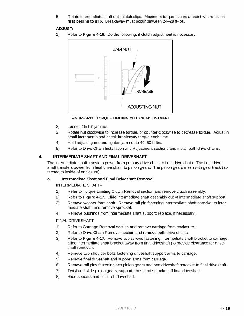
32DF9T02.C 4 - 19
5) Rotate intermediate shaft until clutch slips. Maximum torque occurs at point where clutch first begins to slip. Breakaway must occur between 24–28 ft-lbs.
ADJUST: 1) Refer to Figure 4-19. Do the following, if clutch adjustment is necessary:
2) Loosen 15/16" jam nut. 3) Rotate nut clockwise to increase torque, or counter-clockwise to decrease torque. Adjust in
small increments and check breakaway torque each time. 4) Hold adjusting nut and tighten jam nut to 40–50 ft-lbs. 5) Refer to Drive Chain Installation and Adjustment sections and install both drive chains.
4. INTERMEDIATE SHAFT AND FINAL DRIVESHAFT The intermediate shaft transfers power from primary drive chain to final drive chain. The final drive-shaft transfers power from final drive chain to pinion gears. The pinion gears mesh with gear track (at-tached to inside of enclosure).
a. Intermediate Shaft and Final Driveshaft Removal INTERMEDIATE SHAFT– 1) Refer to Torque Limiting Clutch Removal section and remove clutch assembly. 2) Refer to Figure 4-17. Slide intermediate shaft assembly out of intermediate shaft support. 3) Remove washer from shaft. Remove roll pin fastening intermediate shaft sprocket to inter-
mediate shaft, and remove sprocket. 4) Remove bushings from intermediate shaft support; replace, if necessary.
FINAL DRIVESHAFT– 1) Refer to Carriage Removal section and remove carriage from enclosure. 2) Refer to Drive Chain Removal section and remove both drive chains. 3) Refer to Figure 4-17. Remove two screws fastening intermediate shaft bracket to carriage.
Slide intermediate shaft bracket away from final driveshaft (to provide clearance for drive-shaft removal).
4) Remove two shoulder bolts fastening driveshaft support arms to carriage. 5) Remove final driveshaft and support arms from carriage. 6) Remove roll pins fastening two pinion gears and one driveshaft sprocket to final driveshaft. 7) Twist and slide pinion gears, support arms, and sprocket off final driveshaft. 8) Slide spacers and collar off driveshaft.
ADJUSTING NUT
JAM NUT
INCREASE
FIGURE 4-19: TORQUE LIMITING CLUTCH ADJUSTMENT
32DF9T02.C 4 - 20
b. Intermediate Shaft and Final Driveshaft Installation
INTERMEDIATE SHAFT– NOTE: Refer to Intermediate Shaft Removal section if an intermediate shaft is present.
1) Press new bushings into intermediate shaft support, if necessary. Bearing flange is on out-side of support.
2) Slide intermediate shaft sprocket onto intermediate shaft. Align hole in sprocket hub with corresponding hole in intermediate shaft.
3) Drive new rollpin into sprocket hub and intermediate shaft. 4) Slide intermediate shaft assembly through bushings of intermediate shaft support. Refer to
Figure 4-17 and verify that orientation of intermediate shaft assembly matches illustration (sprocket is near outside of carriage).
5) Refer to Torque Limiting Clutch Installation section. Install and adjust clutch. 6) Refer to Carriage Installation section and install carriage into enclosure.
FINAL DRIVESHAFT– NOTE: Refer to Final Driveshaft Removal section if a final driveshaft is present.
1) Refer to Figure 4-17. Slide driveshaft sprocket onto driveshaft. Align roll pin-hole in sprocket hub with hole in driveshaft.
2) Drive new roll pin into sprocket hub and driveshaft. 3) Press new bushings into driveshaft support arms, if necessary. Bearing flange is on inside
of support arms NOTE: Spring retaining pins on driveshaft support arms must point downward.
4) Slide collar, spacers, and driveshaft support arms onto driveshaft. 5) Slide pinion gears onto driveshaft. Align holes in gear hubs and collar with corresponding
holes on driveshaft. 6) Drive new rollpins into gear hubs, collar, and driveshaft. 7) Position driveshaft assembly in carriage, and fasten support arms with two shoulder bolts
and related hardware. 8) Locate compression springs over spring retaining pins on carriage. Rotate support arms
down onto springs. Verify that both ends of each spring are held by spring retaining pins. 9) Locate intermediate shaft bracket (with intermediate shaft assembly) on top of carriage and
install screws and lock washers. Tighten sufficiently to lock the washers. 10) Refer to Drive Chain Installation section and install the primary and final drive chains. 11) Refer to Carriage Removal section and install carriage into enclosure by reversing removal
steps. Heed all warnings and precautions.
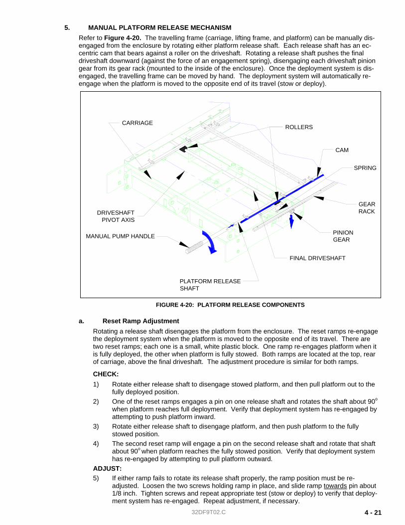
32DF9T02.C 4 - 21
5. MANUAL PLATFORM RELEASE MECHANISM Refer to Figure 4-20. The travelling frame (carriage, lifting frame, and platform) can be manually dis-engaged from the enclosure by rotating either platform release shaft. Each release shaft has an ec-centric cam that bears against a roller on the driveshaft. Rotating a release shaft pushes the final driveshaft downward (against the force of an engagement spring), disengaging each driveshaft pinion gear from its gear rack (mounted to the inside of the enclosure). Once the deployment system is dis-engaged, the travelling frame can be moved by hand. The deployment system will automatically re-engage when the platform is moved to the opposite end of its travel (stow or deploy).
a. Reset Ramp Adjustment Rotating a release shaft disengages the platform from the enclosure. The reset ramps re-engage the deployment system when the platform is moved to the opposite end of its travel. There are two reset ramps; each one is a small, white plastic block. One ramp re-engages platform when it is fully deployed, the other when platform is fully stowed. Both ramps are located at the top, rear of carriage, above the final driveshaft. The adjustment procedure is similar for both ramps.
CHECK: 1) Rotate either release shaft to disengage stowed platform, and then pull platform out to the
fully deployed position. 2) One of the reset ramps engages a pin on one release shaft and rotates the shaft about 90o
when platform reaches full deployment. Verify that deployment system has re-engaged by attempting to push platform inward.
3) Rotate either release shaft to disengage platform, and then push platform to the fully stowed position.
4) The second reset ramp will engage a pin on the second release shaft and rotate that shaft about 90o when platform reaches the fully stowed position. Verify that deployment system has re-engaged by attempting to pull platform outward.
ADJUST: 5) If either ramp fails to rotate its release shaft properly, the ramp position must be re-
adjusted. Loosen the two screws holding ramp in place, and slide ramp towards pin about 1/8 inch. Tighten screws and repeat appropriate test (stow or deploy) to verify that deploy-ment system has re-engaged. Repeat adjustment, if necessary.
ROLLERS
CAM
GEAR
FINAL DRIVESHAFT
DRIVESHAFTPIVOT AXIS
PLATFORM RELEASESHAFT
MANUAL PUMP HANDLE
SPRING
PINION
RACK
GEAR
CARRIAGE
FIGURE 4-20: PLATFORM RELEASE COMPONENTS
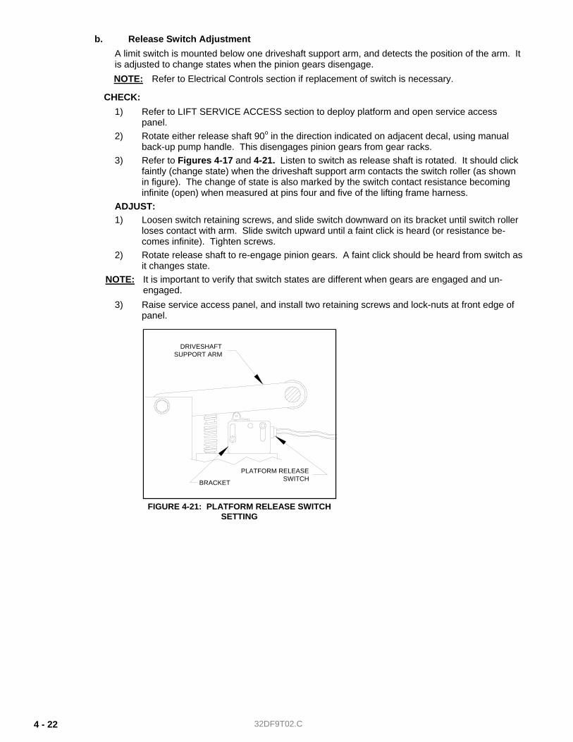
32DF9T02.C 4 - 22
b. Release Switch Adjustment A limit switch is mounted below one driveshaft support arm, and detects the position of the arm. It is adjusted to change states when the pinion gears disengage. NOTE: Refer to Electrical Controls section if replacement of switch is necessary.
CHECK: 1) Refer to LIFT SERVICE ACCESS section to deploy platform and open service access
panel. 2) Rotate either release shaft 90o in the direction indicated on adjacent decal, using manual
back-up pump handle. This disengages pinion gears from gear racks. 3) Refer to Figures 4-17 and 4-21. Listen to switch as release shaft is rotated. It should click
faintly (change state) when the driveshaft support arm contacts the switch roller (as shown in figure). The change of state is also marked by the switch contact resistance becoming infinite (open) when measured at pins four and five of the lifting frame harness.
ADJUST: 1) Loosen switch retaining screws, and slide switch downward on its bracket until switch roller
loses contact with arm. Slide switch upward until a faint click is heard (or resistance be-comes infinite). Tighten screws.
2) Rotate release shaft to re-engage pinion gears. A faint click should be heard from switch as it changes state.
NOTE: It is important to verify that switch states are different when gears are engaged and un-engaged.
3) Raise service access panel, and install two retaining screws and lock-nuts at front edge of panel.
DRIVESHAFTSUPPORT ARM
PLATFORM RELEASESWITCHBRACKET
FIGURE 4-21: PLATFORM RELEASE SWITCHSETTING
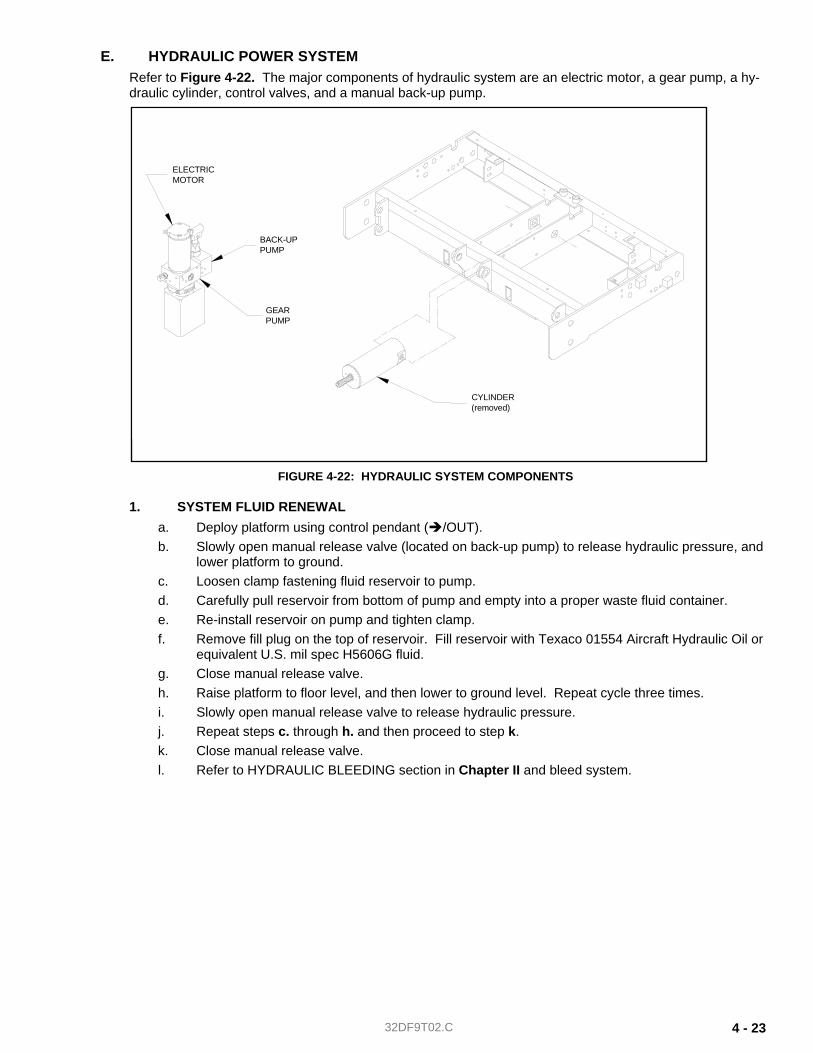
32DF9T02.C 4 - 23
E. HYDRAULIC POWER SYSTEM Refer to Figure 4-22. The major components of hydraulic system are an electric motor, a gear pump, a hy-draulic cylinder, control valves, and a manual back-up pump.
1. SYSTEM FLUID RENEWAL a. Deploy platform using control pendant ( /OUT). b. Slowly open manual release valve (located on back-up pump) to release hydraulic pressure, and
lower platform to ground. c. Loosen clamp fastening fluid reservoir to pump. d. Carefully pull reservoir from bottom of pump and empty into a proper waste fluid container. e. Re-install reservoir on pump and tighten clamp. f. Remove fill plug on the top of reservoir. Fill reservoir with Texaco 01554 Aircraft Hydraulic Oil or
equivalent U.S. mil spec H5606G fluid. g. Close manual release valve. h. Raise platform to floor level, and then lower to ground level. Repeat cycle three times. i. Slowly open manual release valve to release hydraulic pressure. j. Repeat steps c. through h. and then proceed to step k. k. Close manual release valve. l. Refer to HYDRAULIC BLEEDING section in Chapter II and bleed system.
CYLINDER(removed)
ELECTRICMOTOR
BACK-UPPUMP
GEARPUMP
FIGURE 4-22: HYDRAULIC SYSTEM COMPONENTS
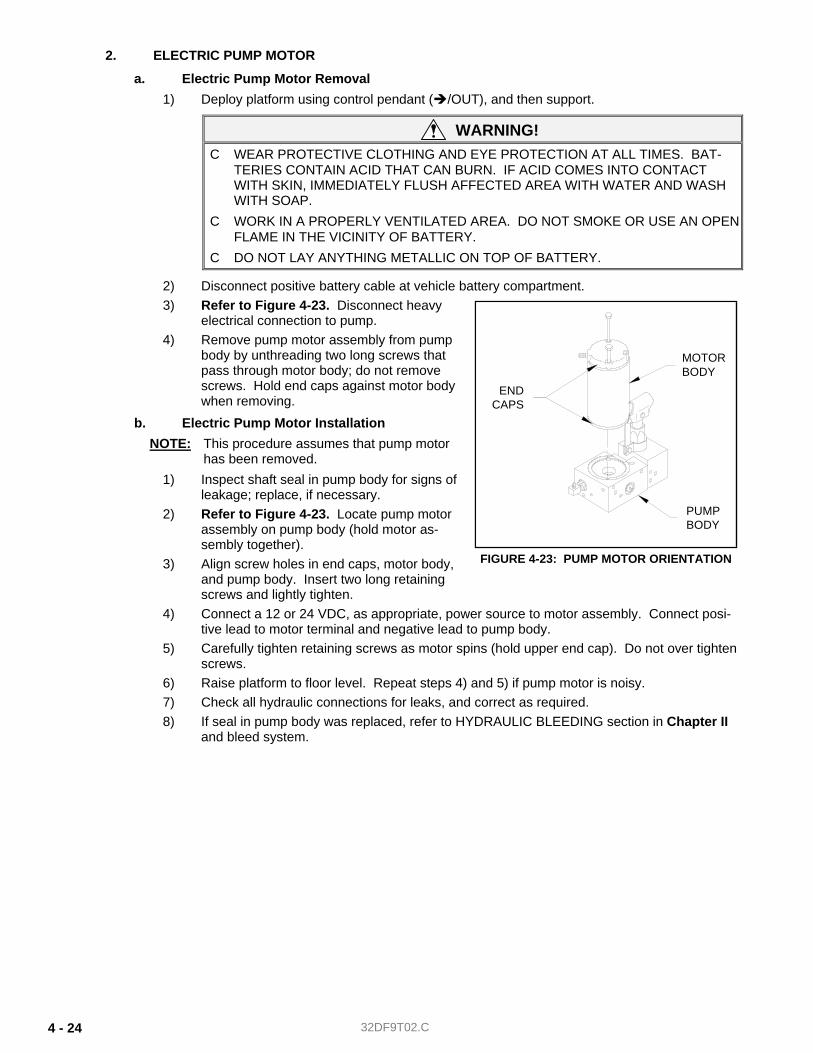
32DF9T02.C 4 - 24
2. ELECTRIC PUMP MOTOR
a. Electric Pump Motor Removal 1) Deploy platform using control pendant ( /OUT), and then support.
WARNING! C WEAR PROTECTIVE CLOTHING AND EYE PROTECTION AT ALL TIMES. BAT-
TERIES CONTAIN ACID THAT CAN BURN. IF ACID COMES INTO CONTACT WITH SKIN, IMMEDIATELY FLUSH AFFECTED AREA WITH WATER AND WASH WITH SOAP.
C WORK IN A PROPERLY VENTILATED AREA. DO NOT SMOKE OR USE AN OPEN FLAME IN THE VICINITY OF BATTERY.
C DO NOT LAY ANYTHING METALLIC ON TOP OF BATTERY.
2) Disconnect positive battery cable at vehicle battery compartment. 3) Refer to Figure 4-23. Disconnect heavy
electrical connection to pump. 4) Remove pump motor assembly from pump
body by unthreading two long screws that pass through motor body; do not remove screws. Hold end caps against motor body when removing.
b. Electric Pump Motor Installation NOTE: This procedure assumes that pump motor
has been removed. 1) Inspect shaft seal in pump body for signs of
leakage; replace, if necessary. 2) Refer to Figure 4-23. Locate pump motor
assembly on pump body (hold motor as-sembly together).
3) Align screw holes in end caps, motor body, and pump body. Insert two long retaining screws and lightly tighten.
4) Connect a 12 or 24 VDC, as appropriate, power source to motor assembly. Connect posi-tive lead to motor terminal and negative lead to pump body.
5) Carefully tighten retaining screws as motor spins (hold upper end cap). Do not over tighten screws.
6) Raise platform to floor level. Repeat steps 4) and 5) if pump motor is noisy. 7) Check all hydraulic connections for leaks, and correct as required. 8) If seal in pump body was replaced, refer to HYDRAULIC BLEEDING section in Chapter II
and bleed system.
PUMPBODY
ENDCAPS
MOTORBODY
FIGURE 4-23: PUMP MOTOR ORIENTATION
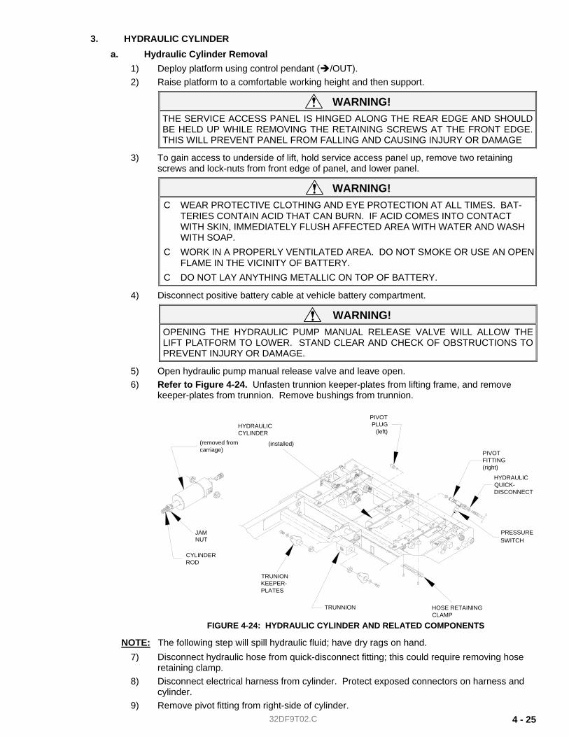
32DF9T02.C 4 - 25
3. HYDRAULIC CYLINDER a. Hydraulic Cylinder Removal
1) Deploy platform using control pendant ( /OUT). 2) Raise platform to a comfortable working height and then support.
WARNING! THE SERVICE ACCESS PANEL IS HINGED ALONG THE REAR EDGE AND SHOULD BE HELD UP WHILE REMOVING THE RETAINING SCREWS AT THE FRONT EDGE. THIS WILL PREVENT PANEL FROM FALLING AND CAUSING INJURY OR DAMAGE
3) To gain access to underside of lift, hold service access panel up, remove two retaining screws and lock-nuts from front edge of panel, and lower panel.
WARNING! C WEAR PROTECTIVE CLOTHING AND EYE PROTECTION AT ALL TIMES. BAT-
TERIES CONTAIN ACID THAT CAN BURN. IF ACID COMES INTO CONTACT WITH SKIN, IMMEDIATELY FLUSH AFFECTED AREA WITH WATER AND WASH WITH SOAP.
C WORK IN A PROPERLY VENTILATED AREA. DO NOT SMOKE OR USE AN OPEN FLAME IN THE VICINITY OF BATTERY.
C DO NOT LAY ANYTHING METALLIC ON TOP OF BATTERY. 4) Disconnect positive battery cable at vehicle battery compartment.
WARNING! OPENING THE HYDRAULIC PUMP MANUAL RELEASE VALVE WILL ALLOW THE LIFT PLATFORM TO LOWER. STAND CLEAR AND CHECK OF OBSTRUCTIONS TO PREVENT INJURY OR DAMAGE.
5) Open hydraulic pump manual release valve and leave open. 6) Refer to Figure 4-24. Unfasten trunnion keeper-plates from lifting frame, and remove
keeper-plates from trunnion. Remove bushings from trunnion.
NOTE: The following step will spill hydraulic fluid; have dry rags on hand. 7) Disconnect hydraulic hose from quick-disconnect fitting; this could require removing hose
retaining clamp. 8) Disconnect electrical harness from cylinder. Protect exposed connectors on harness and
cylinder. 9) Remove pivot fitting from right-side of cylinder.
(installed)
TRUNIONKEEPER-PLATES
(removed fromcarriage)
PIVOTPLUG
(left)
CYLINDERROD
JAMNUT
PIVOTFITTING(right)
PRESSURE SWITCH
HYDRAULICCYLINDER
HYDRAULICQUICK-DISCONNECT
HOSE RETAININGCLAMP
TRUNNION
FIGURE 4-24: HYDRAULIC CYLINDER AND RELATED COMPONENTS
32DF9T02.C 4 - 26
10) Remove pivot plug from left-side of cylinder; this will release cylinder from carriage. 11) Carefully remove cylinder and trunnion assembly from carriage. Remove two bushings
from carriage frame. Loosen jam nut (located behind trunnion), and remove trunnion.
b. Hydraulic Cylinder Installation NOTE: This procedure assumes that hydraulic cylinder has been removed.
1) Refer to Figure 4-24. Assemble jam nut and trunnion onto hydraulic cylinder rod. Install two cylinder pivot bushings into carriage frame (with flanges to inside of frame).
2) Insert rear of hydraulic cylinder up into center of carriage, and push cylinder as far up and back as possible. Swing front of cylinder up into carriage.
3) Align cylinder with bushings, and install pivot plug through carriage frame bushing and into left-side of cylinder.
4) Install pivot fitting (with hydraulic Quick-Disconnect) through carriage frame bushing and into right-side of cylinder.
5) Connect hydraulic hose to Quick-Disconnect fitting. Fasten hose retaining clamp to car-riage.
6) Verify that hydraulic pump manual release valve is closed. Extend trunnion out to tabs on lifting frame with manual backup pump.
7) Install two bushings in trunnion, and then insert keeper-plates through lifting frame tabs and into trunnion bushings. Fasten keeper-plates to lifting frame.
8) Refer to HYDRAULIC BLEEDING section in Chapter II and bleed system. 9) Raise platform to maximum height possible using manual back-up pump. Compare this
height to vehicle floor height and note whether platform needs to be raised or lowered. 10) Insert a 3/8” hex wrench, or 3/8” hex drive, into end of cylinder rod. Turn rod clockwise to
raise platform, and counterclockwise to lower. Adjust to height needed for entry into vehi-cle. Tighten jam nut against trunnion.
NOTE: It could be necessary to lift platform slightly to make turning of cylinder rod easier. 11) Refer to Platform Stow Height Adjustment section in Chapter II, and program stow height.
Program intermediate height, if necessary.
4. PRESSURE SWITCH ADJUSTMENT An adjustable, pressure sensing, electrical switch is installed in the hydraulic line connected to the hy-draulic cylinder. The switch detects the presence of a load, of 75 lbs or greater, on the deployed plat-form. Correct adjustment of switch inhibits a loaded platform from stowing into vehicle, providing a safety factor for lift users. Refer to the Pressure Switch Adjustment section in Chapter II after doing major repair or replacement of components in the hydraulic system.
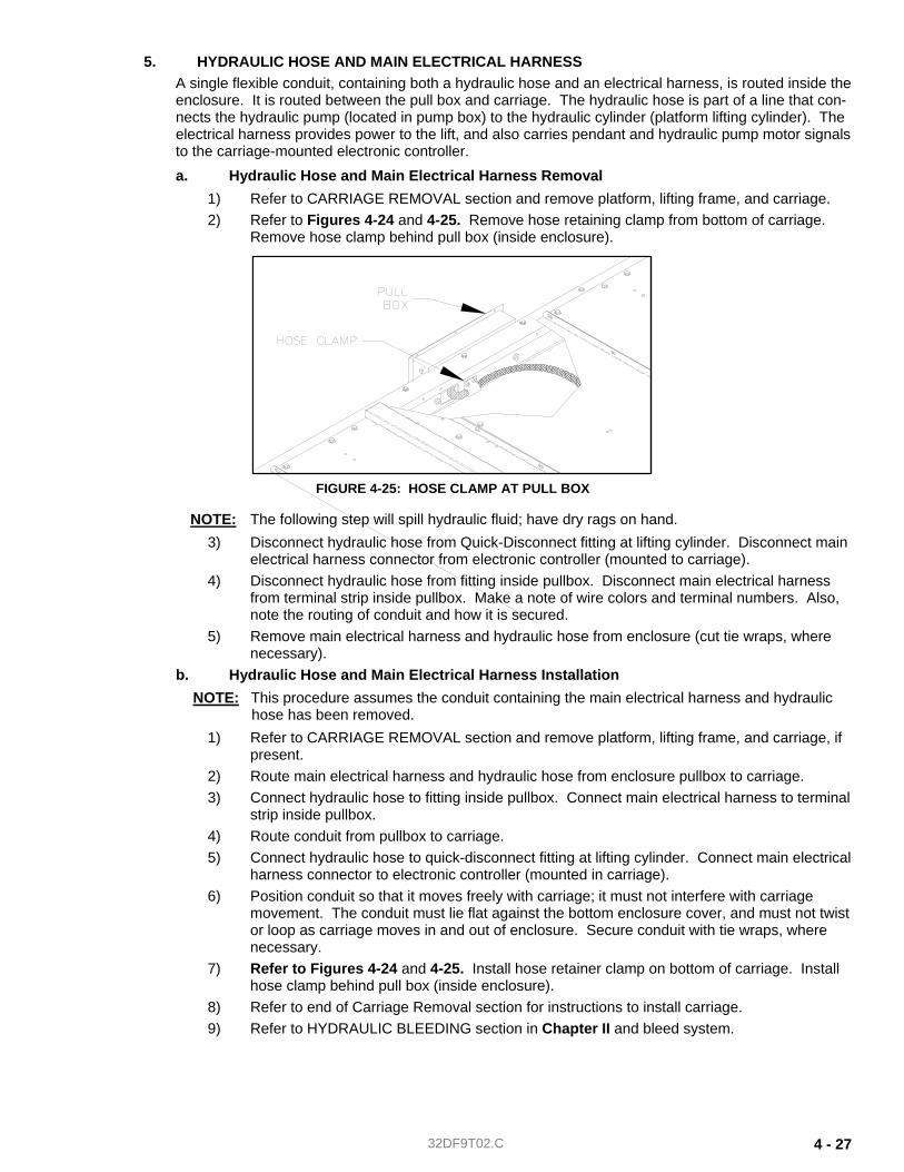
32DF9T02.C 4 - 27
5. HYDRAULIC HOSE AND MAIN ELECTRICAL HARNESS A single flexible conduit, containing both a hydraulic hose and an electrical harness, is routed inside the enclosure. It is routed between the pull box and carriage. The hydraulic hose is part of a line that con-nects the hydraulic pump (located in pump box) to the hydraulic cylinder (platform lifting cylinder). The electrical harness provides power to the lift, and also carries pendant and hydraulic pump motor signals to the carriage-mounted electronic controller. a. Hydraulic Hose and Main Electrical Harness Removal
1) Refer to CARRIAGE REMOVAL section and remove platform, lifting frame, and carriage. 2) Refer to Figures 4-24 and 4-25. Remove hose retaining clamp from bottom of carriage.
Remove hose clamp behind pull box (inside enclosure).
NOTE: The following step will spill hydraulic fluid; have dry rags on hand. 3) Disconnect hydraulic hose from Quick-Disconnect fitting at lifting cylinder. Disconnect main
electrical harness connector from electronic controller (mounted to carriage). 4) Disconnect hydraulic hose from fitting inside pullbox. Disconnect main electrical harness
from terminal strip inside pullbox. Make a note of wire colors and terminal numbers. Also, note the routing of conduit and how it is secured.
5) Remove main electrical harness and hydraulic hose from enclosure (cut tie wraps, where necessary).
b. Hydraulic Hose and Main Electrical Harness Installation NOTE: This procedure assumes the conduit containing the main electrical harness and hydraulic
hose has been removed. 1) Refer to CARRIAGE REMOVAL section and remove platform, lifting frame, and carriage, if
present. 2) Route main electrical harness and hydraulic hose from enclosure pullbox to carriage. 3) Connect hydraulic hose to fitting inside pullbox. Connect main electrical harness to terminal
strip inside pullbox. 4) Route conduit from pullbox to carriage. 5) Connect hydraulic hose to quick-disconnect fitting at lifting cylinder. Connect main electrical
harness connector to electronic controller (mounted in carriage). 6) Position conduit so that it moves freely with carriage; it must not interfere with carriage
movement. The conduit must lie flat against the bottom enclosure cover, and must not twist or loop as carriage moves in and out of enclosure. Secure conduit with tie wraps, where necessary.
7) Refer to Figures 4-24 and 4-25. Install hose retainer clamp on bottom of carriage. Install hose clamp behind pull box (inside enclosure).
8) Refer to end of Carriage Removal section for instructions to install carriage. 9) Refer to HYDRAULIC BLEEDING section in Chapter II and bleed system.
FIGURE 4-25: HOSE CLAMP AT PULL BOX
32DF9T02.C 4 - 28
F. ELECTRICAL CONTROLS 1. GENERAL LIMIT SWITCH REPLACEMENT
There are several limit switches installed in the platform and carriage. The switches are hard-wired to their harnesses at the factory, but can be replaced in the field. Replacement switches are supplied with three wire leads (pigtails). Use this procedure to wire a replacement switch into a harness.
WARNING! C WEAR PROTECTIVE CLOTHING AND EYE PROTECTION AT ALL TIMES. BAT-
TERIES CONTAIN ACID THAT CAN BURN. IF ACID COMES INTO CONTACT WITH SKIN, IMMEDIATELY FLUSH AFFECTED AREA WITH WATER AND WASH WITH SOAP.
C WORK IN A PROPERLY VENTILATED AREA. DO NOT SMOKE OR USE AN OPEN FLAME IN THE VICINITY OF BATTERY.
C DO NOT LAY ANYTHING METALLIC ON TOP OF BATTERY.
a. Disconnect positive battery cable at vehicle battery compartment. b. Note colors of wire leads on switch to be replaced (red lead and blue lead, red lead and yellow
lead, etc). Cut leads close to switch body. Strip a ¼” of insulation off remaining leads. c. Cut wire leads on replacement switch to an appropriate length; cut leads long if unsure of exact
length. Strip ends of wires ¼”. d. Place a 1" length of ¼” shrinkable tubing around each switch wire if you are going to solder the
new connections. Slide tubing away from end of wire. e. Connect each harness lead to appropriate lead on replacement switch. [Contact Ricon Product
Support if replacement switch leads are a different color than switch being replaced.] The leads can be joined with crimp-on butt connectors, or soldered.
f. Verify integrity of each connection by attempting to pull it apart. g. Slide the shrinkable tubing over soldered connections and shrink with a heat gun. h. Cut unused switch lead close to switch body. i. Remove original switch from its bracket and mount replacement switch in its place. j. Refer to appropriate Switch Adjustment section in this chapter and set switch position. k. Reconnect positive battery cable at vehicle battery compartment.
2. ELECTRONIC CONTROLLER REPLACEMENT The electronic circuitry inside the controller box receives command inputs from the pendant. It also monitors and controls all lift functions. There are no parts in controller that can be replaced in the field; the entire controller must be replaced if at fault. Verify that replacement controller is appropriate for the application being worked on.
CAUTION! The electronic controllers used in the various Ricon Mirage models are visually similar and physically interchangeable. However, their programming and internal circuitry are different, and they must not be installed in a lift they were not designed for.
a. Fully deploy lift. b. The controller is taken out of carriage from below on some models (through access hatch), but
can be removed from above on others.
WARNING! THE SERVICE ACCESS PANEL IS HINGED ALONG THE REAR EDGE AND SHOULD BE HELD UP WHILE REMOVING THE RETAINING SCREWS AT THE FRONT EDGE. THIS WILL PREVENT PANEL FROM FALLING AND CAUSING INJURY OR DAMAGE
c. To gain access to underside of lift, hold service access panel up, remove two retaining screws and lock-nuts from front edge of panel, and lower panel.
d. Disconnect three harness connectors from controller. e. Remove two Phillips screws fastening connector-end of controller to its mounting bracket.

32DF9T02.C 4 - 29
f. Slide controller mounting loop off of other bracket and remove controller from carriage. g. Position replacement controller inside carriage. Slide loop on top of housing onto mounting
bracket tab. h. Re-install two Phillips screws. i. Connect three harness connectors to controller; tighten connectors securely.
NOTE: Each connector is uniquely keyed, and cannot be intermixed. However, do not attempt to force a connector plug onto wrong receptacle.
j. Raise service access panel, and install two retaining screws and lock-nuts at front edge of panel. k. Reconnect positive battery cable at vehicle battery compartment.
3. HYDRAULIC HOSE AND MAIN ELECTRICAL HARNESS A single flexible conduit, containing both a hydraulic hose and an electrical harness, is routed inside the enclosure. It is routed between the pull box and carriage. The hydraulic hose is part of a line that con-nects the hydraulic pump (located in pump box) to the hydraulic cylinder (platform lifting cylinder). The electrical harness provides power to the lift, and also carries pendant and hydraulic pump motor signals to the carriage-mounted electronic controller. Refer to the Hydraulic Hose and Main Electrical Harness paragraph in the Hydraulic Power System section for removal and installation instructions.

32DF9T02.C 4 - 30
-This page intentionally left blank-
-BACK TO PREVIOUS CHAPTER- -GO TO NEXT CHAPTER-
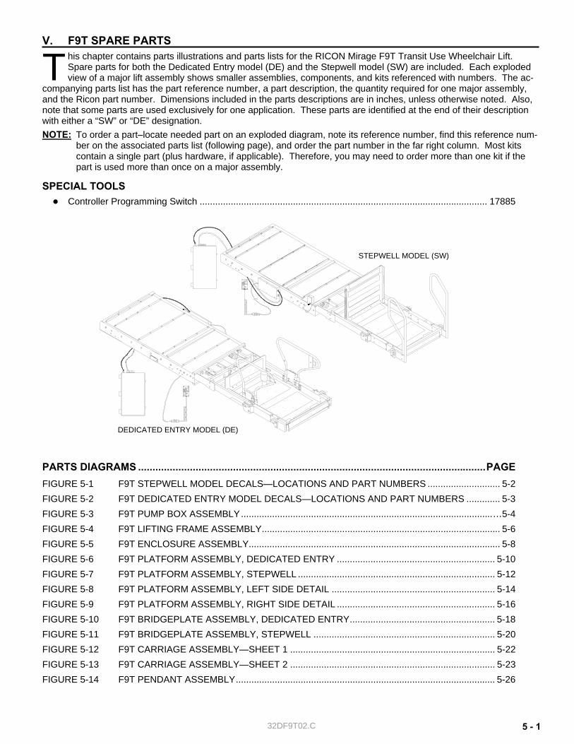
32DF9T02.C 5 - 1
V. F9T SPARE PARTS his chapter contains parts illustrations and parts lists for the RICON Mirage F9T Transit Use Wheelchair Lift. Spare parts for both the Dedicated Entry model (DE) and the Stepwell model (SW) are included. Each exploded view of a major lift assembly shows smaller assemblies, components, and kits referenced with numbers. The ac-
companying parts list has the part reference number, a part description, the quantity required for one major assembly, and the Ricon part number. Dimensions included in the parts descriptions are in inches, unless otherwise noted. Also, note that some parts are used exclusively for one application. These parts are identified at the end of their description with either a “SW” or “DE” designation. NOTE: To order a part–locate needed part on an exploded diagram, note its reference number, find this reference num-
ber on the associated parts list (following page), and order the part number in the far right column. Most kits contain a single part (plus hardware, if applicable). Therefore, you may need to order more than one kit if the part is used more than once on a major assembly.
SPECIAL TOOLS ● Controller Programming Switch ............................................................................................................... 17885
PARTS DIAGRAMS .........................................................................................................................PAGE FIGURE 5-1 F9T STEPWELL MODEL DECALS—LOCATIONS AND PART NUMBERS ............................ 5-2 FIGURE 5-2 F9T DEDICATED ENTRY MODEL DECALS—LOCATIONS AND PART NUMBERS ............. 5-3 FIGURE 5-3 F9T PUMP BOX ASSEMBLY.................................................................................................…5-4 FIGURE 5-4 F9T LIFTING FRAME ASSEMBLY............................................................................................ 5-6 FIGURE 5-5 F9T ENCLOSURE ASSEMBLY................................................................................................. 5-8 FIGURE 5-6 F9T PLATFORM ASSEMBLY, DEDICATED ENTRY ............................................................. 5-10 FIGURE 5-7 F9T PLATFORM ASSEMBLY, STEPWELL ............................................................................ 5-12 FIGURE 5-8 F9T PLATFORM ASSEMBLY, LEFT SIDE DETAIL ............................................................... 5-14 FIGURE 5-9 F9T PLATFORM ASSEMBLY, RIGHT SIDE DETAIL ............................................................. 5-16 FIGURE 5-10 F9T BRIDGEPLATE ASSEMBLY, DEDICATED ENTRY........................................................ 5-18 FIGURE 5-11 F9T BRIDGEPLATE ASSEMBLY, STEPWELL ...................................................................... 5-20 FIGURE 5-12 F9T CARRIAGE ASSEMBLY—SHEET 1 ............................................................................... 5-22 FIGURE 5-13 F9T CARRIAGE ASSEMBLY—SHEET 2 ............................................................................... 5-23 FIGURE 5-14 F9T PENDANT ASSEMBLY.................................................................................................... 5-26
T
DEDICATED ENTRY MODEL (DE)
STEPWELL MODEL (SW)
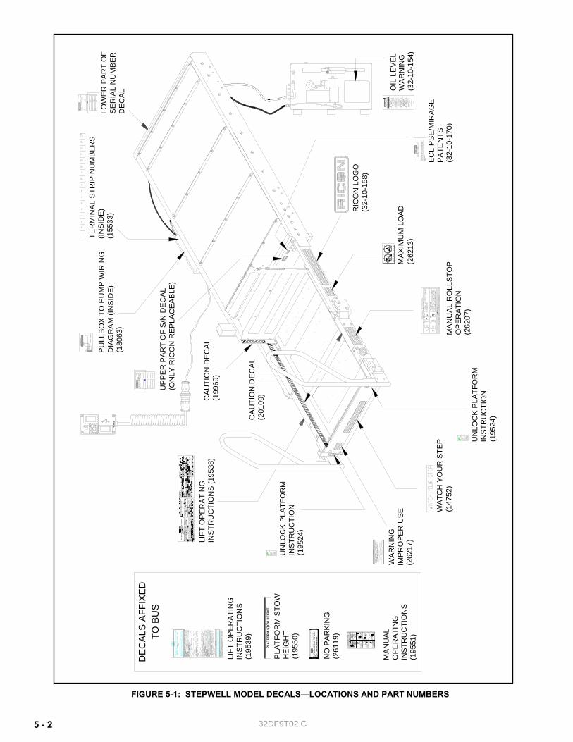
32DF9T02.C 5 - 2
FIGURE 5-1: STEPWELL MODEL DECALS—LOCATIONS AND PART NUMBERS
MA
XIM
UM
LO
AD(2
6213
)Th
is p
rodu
ct is
cov
ered
by
one
or m
ore
of th
e fo
llow
ing
pate
nts:
U
.S. P
aten
ts N
os. x
,xxx
,xxx
; x,x
xx,x
xx; x
,xxx
,xxx
; Aus
trailia
n P
aten
t No.
xxx
xxx;
GB
2,x
xx,x
xx, B
(UK
); G
erm
an P
aten
t No.
xx
xxxx
xx.x
-xx;
Fre
nch
pate
nt N
o. x
-xxx
-xxx
; Oth
er U
.S. a
nd fo
reig
n pa
tent
s pe
ndin
gxx
-xx-
xxx
UP
PE
R P
AR
T O
F S
/N D
ECA
L(O
NLY
RIC
ON
RE
PLA
CE
AB
LE)
EC
LIP
SE
/MIR
AGE
PA
TEN
TS(3
2-10
-170
)
LOW
ER
PAR
T O
F S
ER
IAL
NU
MBE
R
DEC
AL
UN
LOC
K P
LATF
OR
M
INS
TRU
CTI
ON
(1
9524
)
UN
LOC
K PL
ATFO
RM
IN
STR
UC
TIO
N(1
9524
)
TER
MIN
AL
STR
IP N
UM
BER
S(IN
SID
E)
(155
33) (3
2-10
-158
)R
ICO
N L
OG
O
MA
NU
AL
RO
LLST
OP
O
PE
RA
TIO
N(2
6207
)
(147
52)
WAT
CH
YO
UR
STE
P
MAN
UAL
OPE
RA
TIN
GIN
STR
UC
TIO
NS
(195
51)
PLE
AS
E D
ON
'T P
AR
KW
ITH
IN 8
FE
ET
NO
PA
RK
ING
(261
19)
DE
CA
LS A
FFIX
ED
WAR
NIN
GIM
PR
OPE
R U
SE(2
6217
)LIFT
OP
ER
ATI
NG
IN
STR
UC
TIO
NS
(195
38)
LIFT
OP
ER
ATI
NG
IN
STR
UC
TIO
NS
(195
39)
CA
UTI
ON
DE
CA
L (2
0109
)
TO B
US
PARK
SAF
ELY,
CLE
AR A
REA,
OPE
N DOO
RSC
AU
TIO
N
MA
NU
AL
OP
ER
AT
ING
INST
RU
CTI
ON
SRI
CON
MIR
AGE
F9T
STEP
WEL
L W
HEEL
CHAI
R AN
D ST
ANDE
E LIFT
OIL
LE
VEL
(32-
10-1
54)
WA
RN
ING
PU
LLB
OX
TO
PU
MP
WIR
ING
D
IAG
RA
M (I
NS
IDE
)(1
8063
)
CA
UTI
ON
DE
CA
L (1
9969
)
PLA
TFO
RM
ST
OW
HE
IGH
T
PLA
TFO
RM
STO
W
HE
IGH
T(1
9550
)
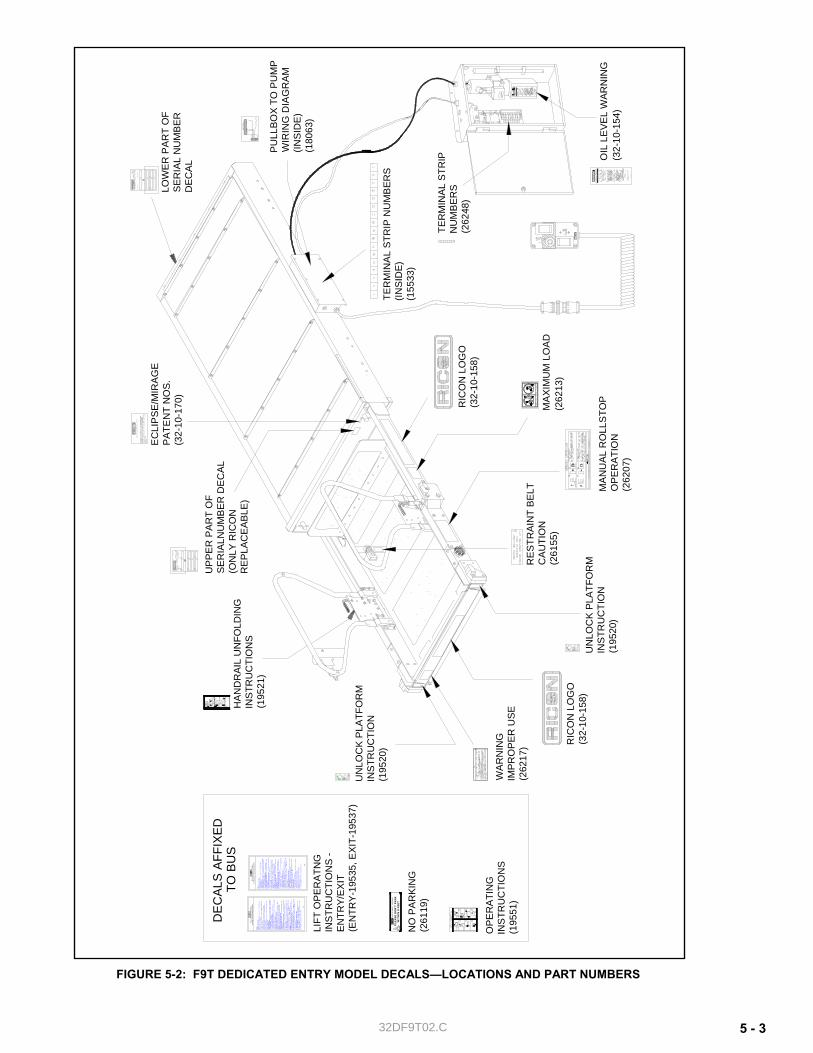
32DF9T02.C 5 - 3
FIGURE 5-2: F9T DEDICATED ENTRY MODEL DECALS—LOCATIONS AND PART NUMBERS
MA
XIM
UM
LO
AD
(262
13)
PLE
AS
E D
ON
'T P
AR
KW
ITH
IN 8
FE
ET
NO
PA
RKI
NG
(261
19)
Ric
on w
heel
chai
r Lift
(RW
L) &
slid
ing
Doo
r O
pera
ting
Inst
ruct
ions
Ric
on w
heel
chai
r Lift
(RW
L) &
slid
ing
Doo
r O
pera
ting
Inst
ruct
ions
EXI
T -
PRE
PARA
TIO
N F
OR
US
E:Fo
llow
the
prep
arat
ions
des
crib
ed o
n th
e "E
NTRY
" ins
truct
ions
dec
al.
TO E
XIT
VEHI
CLE
:1.
DEP
LOY
PLA
TFO
RM:
Pre
ss ⇒
/OUT
but
ton
until
pla
tform
is fu
lly d
eplo
yed.
2. R
AIS
E HA
NDR
AILS
: L
ift R
IGHT
han
drai
l and
eng
age
slam
lock
, the
n lift
LE
FT h
andr
ail a
nd e
ngag
e its
sla
m lo
ck.
3. B
UCK
LE O
CCUP
ANT
REST
RAI
NT
BELT
to e
nabl
e lift
con
trol.
4. P
ART
IALL
Y R
AIS
E PL
ATF
ORM
: P
ress
⇑/U
P bu
tton
until
pla
tform
sto
ps
just
bel
ow fl
oor l
evel
.5.
OP
EN W
HE
ELCH
AIR
ACC
ESS
DOO
R: U
nlat
ch w
heel
chai
r acc
ess
door
and
pu
ll op
en 3
to 4
inch
es; d
oor w
ill th
en o
pen
auto
mat
ically
.6.
RA
ISE
PLAT
FORM
: P
ress
⇑/U
P bu
tton
until
pla
tform
sto
ps a
t flo
or le
vel.
7. B
OA
RD
PLA
TFO
RM:
Pos
ition
whe
elch
air i
n ce
nter
of p
latfo
rm, f
acin
g ou
twar
d if
poss
ible
, and
adv
ise
occu
pant
to lo
ck w
heel
chai
r bra
kes.
STA
NDE
ES s
tand
in c
ente
r of p
latfo
rm a
nd fi
rmly
gra
sp h
andr
ails.
8. P
ART
IALL
Y LO
WER
PLA
TFO
RM:
Pre
ss ⇓
/DO
WN
butto
n un
til p
latfo
rm
stop
s ju
st b
elow
floo
r lev
el.
WAR
NIN
G!
Ver
ify th
at p
asse
nger
s ar
e cl
ear o
f whe
elch
air a
cces
s do
or!
9. C
LOS
E W
HEE
LCHA
IR A
CCES
S DO
OR:
Clo
se d
oor 3
to 4
inch
es; d
oor
will
then
clo
se a
utom
atic
ally.
Pus
h do
or to
latc
h.10
. LO
WER
PLA
TFOR
M:
Pre
ss ⇓
/DO
WN
but
ton
until
pla
tform
sto
ps a
t gro
und
leve
l, an
d ro
llsto
p op
ens
com
plet
ely.
11. U
NBUC
KLE
OC
CUPA
NT R
ESTR
AINT
BEL
T.12
. EXI
T P
LAT
FOR
M:
Adv
ise
pass
enge
rs to
car
eful
ly d
epar
t pla
tform
.13
. PAR
TIAL
LY S
TOW
PLA
TFO
RM:
Pre
ss ⇐
/IN b
utto
n pl
us re
d ST
O-G
ARD
LO
CK
OUT
but
ton
until
pla
tform
reac
hes S
TOW
leve
l and
be
gins
to m
ove
inw
ard.
Rel
ease
but
tons
.14
. UNB
UCKL
E O
CCU
PANT
RES
TRAI
NT B
ELT.
15. L
OW
ER H
AND
RAIL
S:
Lift
the
LEFT
sla
m lo
ck h
andl
e an
d lo
wer h
andr
ail t
o pl
atfo
rm.
Lift
RIG
HT s
lam
lock
han
dle
and
lowe
r han
drai
l.16
. STO
W P
LAT
FORM
: P
ress
⇐/IN
but
ton
plus
red
STO
-GA
RD L
OC
KOU
T bu
tton
until
pla
tform
is fu
lly s
tow
ed in
side
enclo
sure
.S
ECUR
E FO
R TR
AVEL
:1.
Ret
urn
RWL
pend
ant t
o pe
ndan
t tra
y.2.
Tur
n R
WL
lift k
ey to
"OFF
"; th
e po
wer l
ight
on
the
pend
ant t
urns
off
and
the
air l
atch
es e
ngag
e th
e wh
eelc
hair
acce
ss d
oor.
3. C
lose
RW
L fli
p-do
or, l
ock
door
, and
rem
ove
key.
CA
UTI
ON!
Ver
ify th
at R
WL
flip-
door
is la
tched
sec
urel
y!4.
Tur
n RW
L da
sh k
ey to
"OFF
".5.
Loc
k up
per s
lidin
g w
heel
chai
r acc
ess
door
with
For
d-lik
e ke
y.
ENT
RY -
PRE
PARA
TIO
N F
OR
USE
:V
erify
that
par
king
bra
ke is
set
, tra
nsm
issio
n is
in "N
", an
d RW
L da
sh k
ey is
tu
rned
"ON"
bef
ore
oper
atin
g RW
L.Th
e sm
all R
WL
flip-
door
mus
t be
unlo
cked
and
fu
lly o
pen;
floo
dlig
hts
will
illum
inat
e do
or o
peni
ng.
NO
TE:
Flip
-doo
r key
can
not b
e re
mov
ed w
hen
door
is u
nloc
ked.
Turn
RW
L lif
t key
at r
ight
sid
e of
lift
"ON
"; th
is u
nlat
ches
upp
er s
lidin
g w
heel
chai
r acc
ess
door
.S
tand
at r
ear o
f RW
L w
heel
chai
r acc
ess
door
with
RW
L pe
ndan
t; th
e pe
ndan
t po
wer
ligh
t sho
uld
be "O
N".
TO E
NTE
R V
EHIC
LE:
1. D
EPL
OY P
LATF
ORM
: P
ress
/O
UT b
utto
n un
til p
latfo
rm is
fully
dep
loye
d.2.
RA
ISE
HA
NDRA
ILS:
Lift
RIG
HT h
andr
ail a
nd e
ngag
e sl
am lo
ck, t
hen
lift
LEFT
han
drai
l and
eng
age
its s
lam
lock
.3.
BU
CKLE
OC
CUP
ANT
REST
RAIN
T BE
LT to
ena
ble
lift c
ontro
l.4.
LO
WE
R PL
ATFO
RM:
Pre
ss ⇓
/DO
WN
but
ton
until
plat
form
sto
ps a
t gro
und
leve
l and
rolls
top
open
s co
mpl
etel
y.5.
UN
BUCK
LE O
CCUP
ANT
REST
RAIN
T BE
LT.
6. B
OA
RD
PLAT
FORM
: P
ositi
on w
heel
chai
r in
cent
er o
f pla
tform
, fac
ing
outw
ard
if po
ssib
le, a
nd a
dvis
e oc
cupa
nt to
lock
whe
elch
air b
rake
s.S
TAN
DEE
S s
tand
in c
ente
r of p
latfo
rm a
nd fi
rmly
gra
sp h
andr
ails.
7. B
UCK
LE O
CC
UPAN
T RE
STRA
INT
BELT
.8.
PA
RTIA
LLY
RAIS
E PL
ATFO
RM:
Pre
ss ⇑
/UP
butto
n un
til pl
atfo
rm s
tops
ju
st b
elow
floo
r leve
l.9.
OP
EN
WHE
ELC
HAIR
AC
CESS
DO
OR:
Unl
atch
slid
ing
whe
elch
air a
cces
s do
or a
nd p
ull o
pen
3 to
4 in
ches
; doo
r will
then
ope
n au
tom
atica
lly.
10. R
AIS
E P
LATF
ORM
: P
ress
⇑/U
P bu
tton
until
pla
tform
stop
s at
floo
r lev
el.
11. E
XIT
PLA
TFO
RM:
Adv
ise p
asse
nger
s to
car
eful
ly en
ter v
ehicl
e.12
. LO
WE
R P
LATF
OR
M (S
TOW
): P
ress
⇐/IN
but
ton
plus
red
STO
-GA
RD
LOC
KOUT
but
ton;
low
er p
latfo
rm to
jus
t bel
ow fl
oor l
evel
.W
AR
NIN
G! V
erify
that
pas
seng
ers
are
clea
r of w
heel
chai
r acc
ess
door
!13
. CLO
SE W
HEEL
CHAI
R AC
CESS
DO
OR:
Clo
se d
oor 3
to 4
inch
es; d
oor
will
then
clo
se a
utom
atica
lly.
Push
doo
r to
latc
h.14
. PAR
TIA
LLY
STO
W P
LATF
OR
M:
Pre
ss ⇐
/IN b
utto
n pl
us re
d ST
O-G
ARD
LO
CKO
UT b
utto
n un
til p
latfo
rm re
ache
s ST
OW
leve
l and
be
gins
to m
ove
inwa
rd.
Rele
ase
butto
ns.
15. U
NB
UCKL
E O
CCUP
ANT
RES
TRAI
NT B
ELT
.16
. LO
WE
R H
ANDR
AILS
: L
ift L
EFT
slam
lock
han
dle
and
lowe
r han
drail
to
pla
tform
. Li
ft RI
GHT
sla
m lo
ck h
andl
e an
d lo
wer h
andr
ail.
17. S
TOW
PLA
TFOR
M:
Pre
ss ⇐
/IN b
utto
n pl
us re
d ST
O-G
ARD
LOC
KOUT
bu
tton
until
pla
tform
is fu
lly s
tow
ed in
side
enclo
sure
.
LIFT
OP
ER
ATN
G
INS
TRU
CTI
ON
S -
EN
TRY/
EX
IT(E
NTR
Y-1
9535
, EX
IT-1
9537
)
1953
719
535
DE
CA
LS A
FFIX
ED
WA
RN
ING
IMP
RO
PE
R U
SE
(262
17)
TO B
US
This
pro
duct
is c
over
ed b
y on
e or
mor
e of
the
follo
wing
pat
ents
: U
.S. P
aten
ts N
os. x
,xxx
,xxx
; x,x
xx,x
xx; x
,xxx
,xxx
; Aus
trailia
n P
aten
t No.
xxx
xxx;
GB
2,xx
x,xx
x, B
(UK)
; Ger
man
Pat
ent N
o.
xxxx
xxxx
.x-x
x; F
renc
h pa
tent
No.
x-x
xx-x
xx; O
ther
U.S
. and
fore
ign
pate
nts
pend
ing
xx-x
x-xx
x
UP
PE
R P
AR
T O
F S
ER
IALN
UM
BE
R D
EC
AL
(ON
LY R
ICO
N
RE
PLA
CE
ABL
E)
EC
LIP
SE/M
IRA
GE
PA
TEN
T N
OS
. (3
2-10
-170
)LO
WE
R P
AR
T O
F S
ERIA
L N
UM
BE
R
DEC
AL
RE
STR
AIN
T BE
LT
CA
UTI
ON
(2
6155
)
HA
ND
RAI
L U
NFO
LDIN
G
INS
TRU
CTI
ON
S(1
9521
)
UN
LOC
K PL
ATF
OR
M
INS
TRU
CTI
ON
(1
9520
)
UN
LOC
K P
LATF
OR
M
INS
TRU
CTI
ON
(195
20)
TER
MIN
AL
STR
IP N
UM
BER
S(IN
SID
E)(1
5533
)
(32-
10-1
58)
RIC
ON
LO
GO
MA
NU
AL
RO
LLS
TOP
O
PE
RA
TIO
N(2
6207
)
(32-
10-1
58)
RIC
ON
LO
GO
OPE
RA
TIN
GIN
STR
UC
TIO
NS
(195
51)
OIL
LE
VEL
WAR
NIN
G(3
2-10
-154
)
PU
LLB
OX
TO
PU
MP
W
IRIN
G D
IAG
RA
M(IN
SID
E)
(180
63)
TER
MIN
AL
STR
IPN
UM
BE
RS
(262
48)

32DF9T02.C 5 - 4
FIGURE 5-3: F9T PUMP BOX ASSEMBLY
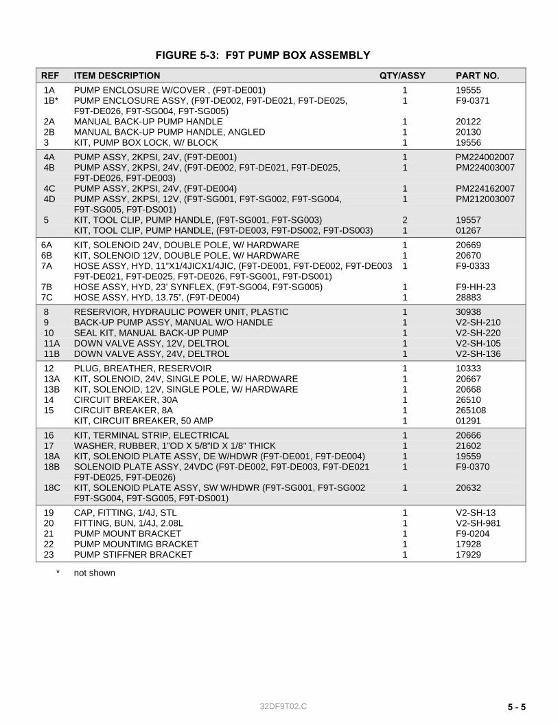
32DF9T02.C 5 - 5
FIGURE 5-3: F9T PUMP BOX ASSEMBLY
REF ITEM DESCRIPTION QTY/ASSY PART NO. 1A PUMP ENCLOSURE W/COVER , (F9T-DE001) 1 19555 1B* PUMP ENCLOSURE ASSY, (F9T-DE002, F9T-DE021, F9T-DE025, 1 F9-0371 F9T-DE026, F9T-SG004, F9T-SG005) 2A MANUAL BACK-UP PUMP HANDLE 1 20122 2B MANUAL BACK-UP PUMP HANDLE, ANGLED 1 20130 3 KIT, PUMP BOX LOCK, W/ BLOCK 1 19556 4A PUMP ASSY, 2KPSI, 24V, (F9T-DE001) 1 PM224002007 4B PUMP ASSY, 2KPSI, 24V, (F9T-DE002, F9T-DE021, F9T-DE025, 1 PM224003007 F9T-DE026, F9T-DE003) 4C PUMP ASSY, 2KPSI, 24V, (F9T-DE004) 1 PM224162007 4D PUMP ASSY, 2KPSI, 12V, (F9T-SG001, F9T-SG002, F9T-SG004, 1 PM212003007 F9T-SG005, F9T-DS001) 5 KIT, TOOL CLIP, PUMP HANDLE, (F9T-SG001, F9T-SG003) 2 19557 KIT, TOOL CLIP, PUMP HANDLE, (F9T-DE003, F9T-DS002, F9T-DS003) 1 01267
6A KIT, SOLENOID 24V, DOUBLE POLE, W/ HARDWARE 1 20669 6B KIT, SOLENOID 12V, DOUBLE POLE, W/ HARDWARE 1 20670 7A HOSE ASSY, HYD, 11”X1/4JICX1/4JIC, (F9T-DE001, F9T-DE002, F9T-DE003 1 F9-0333 F9T-DE021, F9T-DE025, F9T-DE026, F9T-SG001, F9T-DS001) 7B HOSE ASSY, HYD, 23’ SYNFLEX, (F9T-SG004, F9T-SG005) 1 F9-HH-23 7C HOSE ASSY, HYD, 13.75”, (F9T-DE004) 1 28883 8 RESERVIOR, HYDRAULIC POWER UNIT, PLASTIC 1 30938 9 BACK-UP PUMP ASSY, MANUAL W/O HANDLE 1 V2-SH-210 10 SEAL KIT, MANUAL BACK-UP PUMP 1 V2-SH-220 11A DOWN VALVE ASSY, 12V, DELTROL 1 V2-SH-105 11B DOWN VALVE ASSY, 24V, DELTROL 1 V2-SH-136 12 PLUG, BREATHER, RESERVOIR 1 10333 13A KIT, SOLENOID, 24V, SINGLE POLE, W/ HARDWARE 1 20667 13B KIT, SOLENOID, 12V, SINGLE POLE, W/ HARDWARE 1 20668 14 CIRCUIT BREAKER, 30A 1 26510 15 CIRCUIT BREAKER, 8A 1 265108 KIT, CIRCUIT BREAKER, 50 AMP 1 0129116 KIT, TERMINAL STRIP, ELECTRICAL 1 20666 17 WASHER, RUBBER, 1”OD X 5/8”ID X 1/8” THICK 1 21602 18A KIT, SOLENOID PLATE ASSY, DE W/HDWR (F9T-DE001, F9T-DE004) 1 19559 18B SOLENOID PLATE ASSY, 24VDC (F9T-DE002, F9T-DE003, F9T-DE021 1 F9-0370 F9T-DE025, F9T-DE026) 18C KIT, SOLENOID PLATE ASSY, SW W/HDWR (F9T-SG001, F9T-SG002 1 20632 F9T-SG004, F9T-SG005, F9T-DS001) 19 CAP, FITTING, 1/4J, STL 1 V2-SH-13 20 FITTING, BUN, 1/4J, 2.08L 1 V2-SH-981 21 PUMP MOUNT BRACKET 1 F9-0204 22 PUMP MOUNTIMG BRACKET 1 17928 23 PUMP STIFFNER BRACKET 1 17929
* not shown
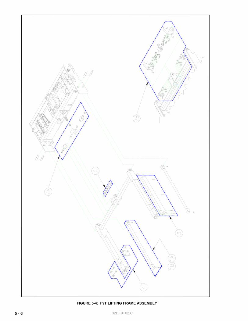
32DF9T02.C 5 - 6
FIGURE 5-4: F9T LIFTING FRAME ASSEMBLY
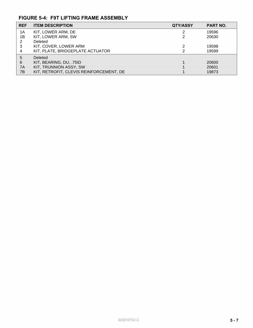
32DF9T02.C 5 - 7
FIGURE 5-4: F9T LIFTING FRAME ASSEMBLY REF ITEM DESCRIPTION QTY/ASSY PART NO. 1A KIT, LOWER ARM, DE 2 19596 1B KIT, LOWER ARM, SW 2 20630 2 Deleted 3 KIT, COVER, LOWER ARM 2 19598 4 KIT, PLATE, BRIDGEPLATE ACTUATOR 2 19599 5 Deleted 6 KIT, BEARING, DU, .75ID 1 20600 7A KIT, TRUNNION ASSY, SW 1 20601 7B KIT, RETROFIT, CLEVIS REINFORCEMENT, DE 1 19873
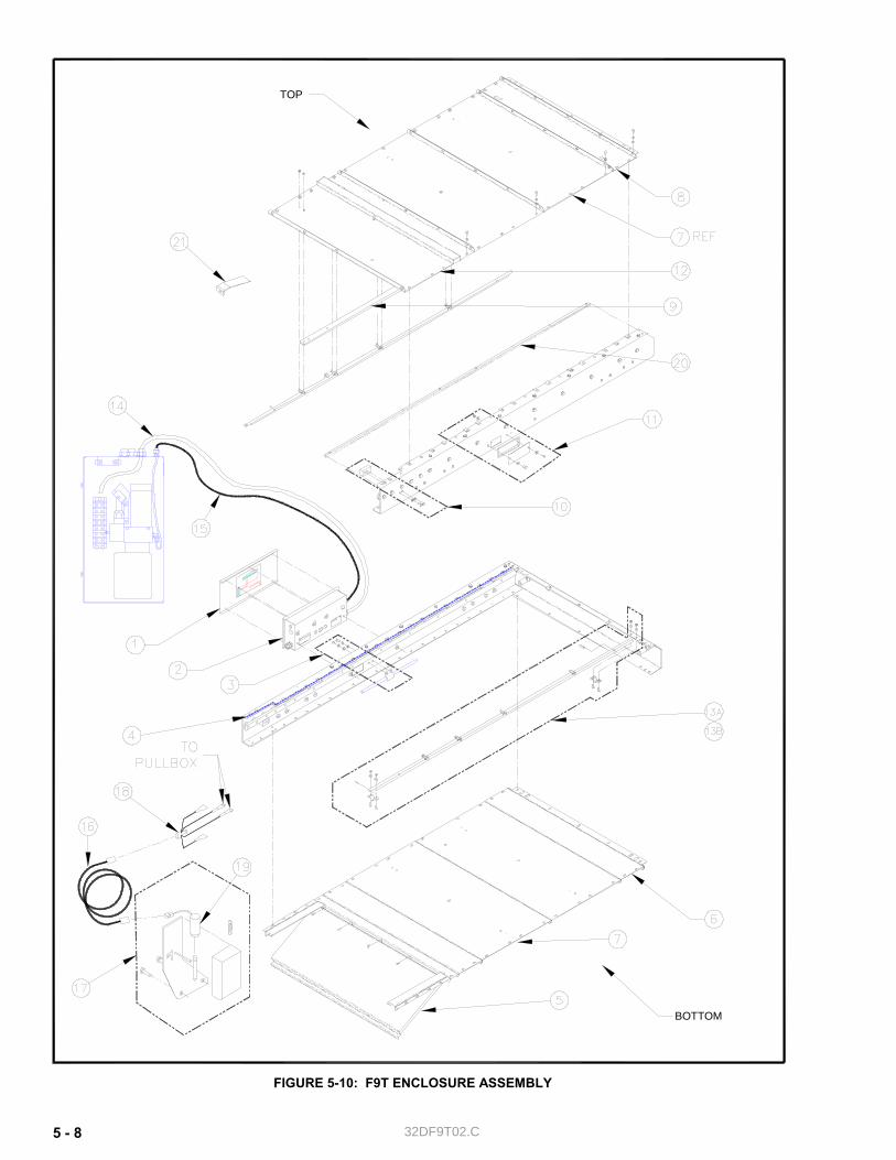
32DF9T02.C 5 - 8
FIGURE 5-10: F9T ENCLOSURE ASSEMBLY
TOP
BOTTOM
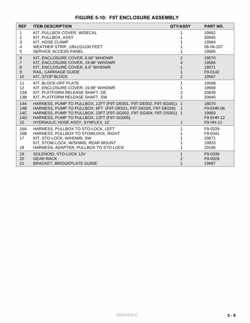
32DF9T02.C 5 - 9
FIGURE 5-10: F9T ENCLOSURE ASSEMBLY REF ITEM DESCRIPTION QTY/ASSY PART NO. 1 KIT, PULLBOX COVER, W/DECAL 1 19562 2 KIT, PULLBOX, ASSY 1 30945 3 KIT, HOSE CLAMP 1 19564 4 WEATHER STRIP, 1/8x1/2x100 FEET 1 06-06-107 5 SERVICE ACCESS PANEL 1 19565 6 KIT, ENCLOSURE COVER, 6.66” W/HDWR 2 19570 7 KIT, ENCLOSURE COVER, 19.98” W/HDWR 4 19566 8 KIT, ENCLOSURE COVER, 6.6” W/HDWR 1 19571 9 RAIL, CARRIAGE GUIDE 1 F9-0142 10 KIT, STOP BLOCK 2 1956711 KIT, BLOCK-OFF PLATE 1 19568 12 KIT, ENCLOSURE COVER, 19.98” W/HDWR 1 19569 13A KIT, PLATFORM RELEASE SHAFT, DE 2 20639 13B KIT, PLATFORM RELEASE SHAFT, SW 2 20640 14A HARNESS, PUMP TO PULLBOX, 12FT (F9T-DE001, F9T-DE002, F9T-SG001) 1 18070 14B HARNESS, PUMP TO PULLBOX, 6FT (F9T-DE021, F9T-DE025, F9T-DE026) 1 F9-EHR-06 14C HARNESS, PUMP TO PULLBOX, 23FT (F9T-SG002, F9T-SG004, F9T-DS001) 1 19993 14D HARNESS, PUMP TO PULLBOX, 12FT (F9T-SG005) F9-EHR-12 15 HYDRAULIC HOSE ASSY, SYNFLEX, 12’ 1 F9-HH-12 16A HARNESS, PULLBOX TO STO-LOCK, LEFT 1 F9-0229 16B HARNESS, PULLBOX TO STOWLOCK, RIGHT 1 F9-0341 17 KIT, STO-LOCK, W/HDWR, SW 1 20671 KIT, STOW LOCK, W/SHIMS, REAR MOUNT 1 19933 18 HARNESS, ADAPTER, PULLBOX TO STO-LOCK 1 20106 19 SOLENOID, STO-LOCK 12V 1 F9-0339 20 GEAR RACK 2 F9-0028 21 BRACKET, BRIDGEPLATE GUIDE 1 19687
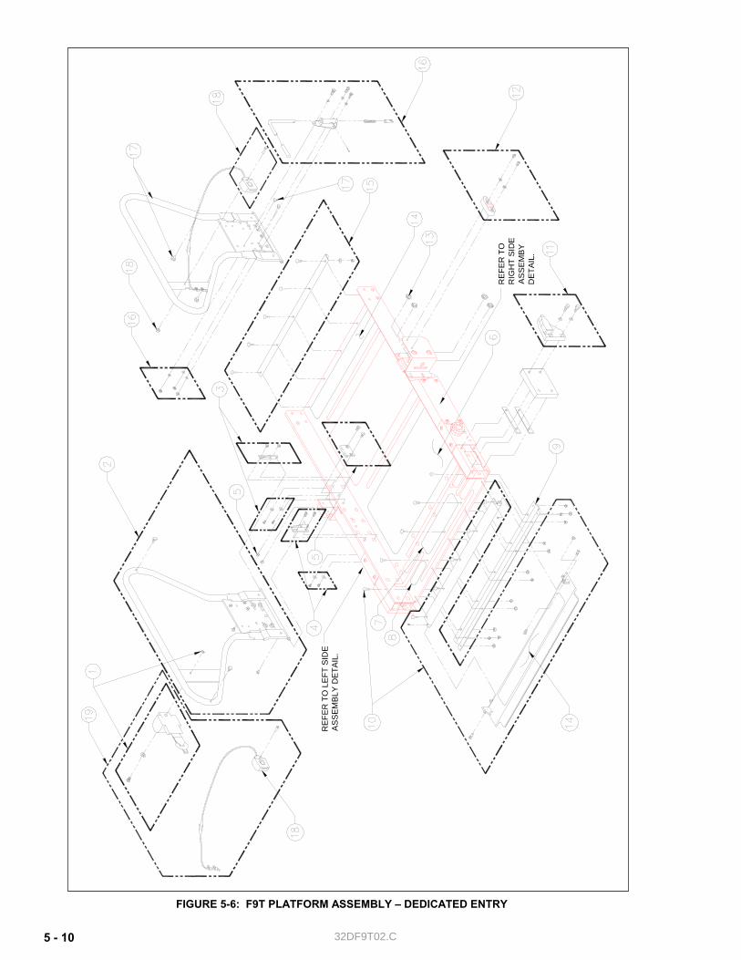
32DF9T02.C 5 - 10
FIGURE 5-6: F9T PLATFORM ASSEMBLY – DEDICATED ENTRY
REF
ER T
O L
EFT
SID
E A
SS
EMB
LY D
ETAI
L.
REF
ER T
O
RIG
HT
SID
E A
SS
EM
BY
DET
AIL.
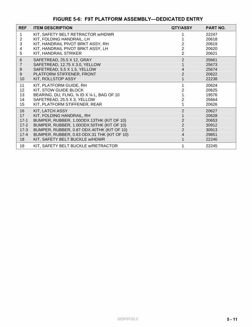
32DF9T02.C 5 - 11
FIGURE 5-6: F9T PLATFORM ASSEMBLY—DEDICATED ENTRY REF ITEM DESCRIPTION QTY/ASSY PART NO. 1 KIT, SAFETY BELT RETRACTOR w/HDWR 1 22247 2 KIT, FOLDING HANDRAIL, LH 1 20618 3 KIT, HANDRAIL PIVOT BRKT ASSY, RH 2 20619 4 KIT, HANDRAIL PIVOT BRKT ASSY, LH 2 20620 5 KIT, HANDRAIL STRIKER 2 206216 SAFETREAD, 25.5 X 12, GRAY 2 25661 7 SAFETREAD, 12.75 X 3.0, YELLOW 1 25673 8 SAFETREAD, 5.5 X 1.5, YELLOW 4 25674 9 PLATFORM STIFFENER, FRONT 2 20622 10 KIT, ROLLSTOP ASSY 1 22238 11 KIT, PLATFORM GUIDE, RH 1 20624 12 KIT, STOW GUIDE BLOCK 2 20625 13 BEARING, DU, FLNG, ¾ ID X ¼ L, BAG OF 10 1 19576 14 SAFETREAD, 25.5 X 3, YELLOW 2 25664 15 KIT, PLATFORM STIFFENER, REAR 1 20626 16 KIT, LATCH ASSY 2 20627 17 KIT, FOLDING HANDRAIL, RH 1 20628 17-1 BUMPER, RUBBER, 1.00ODX.13THK (KIT OF 10) 2 2065317-2 BUMPER, RUBBER, 1.00ODX.50THK (KIT OF 10) 2 30912 17-3 BUMPER, RUBBER, 0.87 ODX.40THK (KIT OF 10) 2 30913 17-4 BUMPER, RUBBER, 0.63 ODX.31 THK (KIT OF 10) 4 29851 18 KIT, SAFETY BELT BUCKLE w/HDWR 1 22246 19 KIT, SAFETY BELT BUCKLE w/RETRACTOR 1 22245
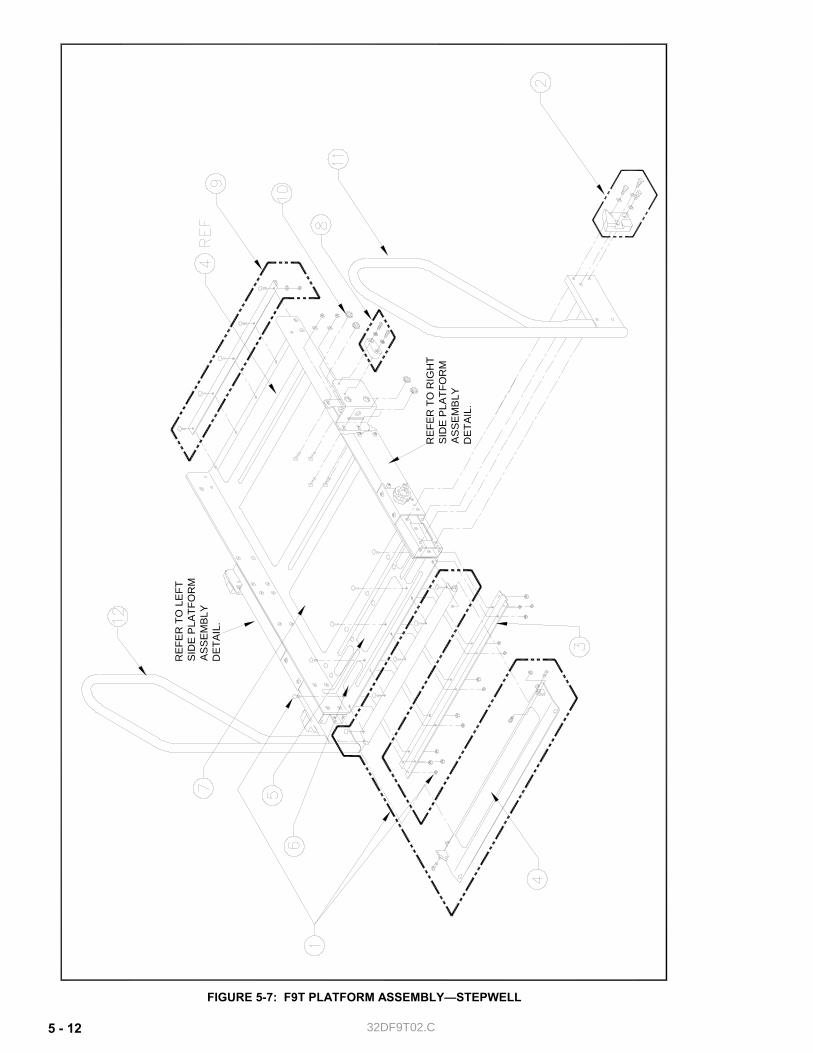
32DF9T02.C 5 - 12
FIGURE 5-7: F9T PLATFORM ASSEMBLY—STEPWELL
REF
ER
TO
LE
FT
SID
E P
LATF
OR
M
AS
SEM
BLY
DET
AIL
.
REF
ER T
O R
IGH
T S
IDE
PLA
TFO
RM
A
SSE
MB
LY
DET
AIL.
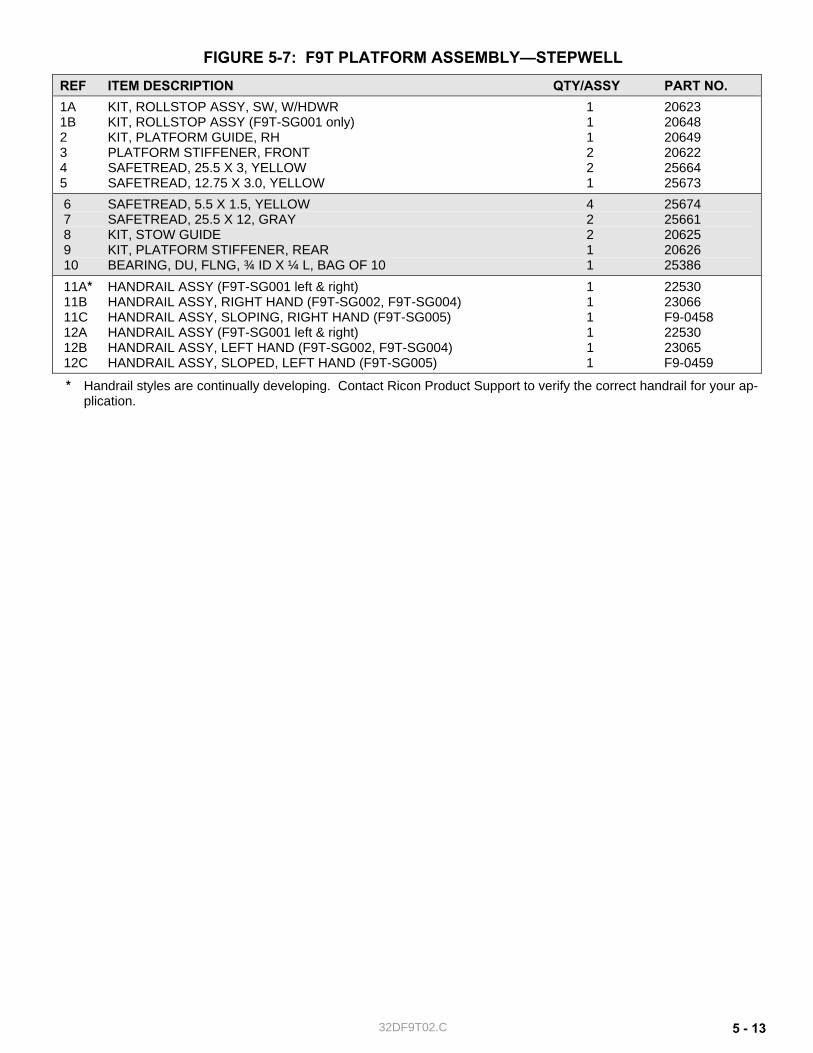
32DF9T02.C 5 - 13
FIGURE 5-7: F9T PLATFORM ASSEMBLY—STEPWELL REF ITEM DESCRIPTION QTY/ASSY PART NO. 1A KIT, ROLLSTOP ASSY, SW, W/HDWR 1 20623 1B KIT, ROLLSTOP ASSY (F9T-SG001 only) 1 20648 2 KIT, PLATFORM GUIDE, RH 1 20649 3 PLATFORM STIFFENER, FRONT 2 20622 4 SAFETREAD, 25.5 X 3, YELLOW 2 25664 5 SAFETREAD, 12.75 X 3.0, YELLOW 1 25673 6 SAFETREAD, 5.5 X 1.5, YELLOW 4 25674 7 SAFETREAD, 25.5 X 12, GRAY 2 25661 8 KIT, STOW GUIDE 2 20625 9 KIT, PLATFORM STIFFENER, REAR 1 20626 10 BEARING, DU, FLNG, ¾ ID X ¼ L, BAG OF 10 1 25386 11A* HANDRAIL ASSY (F9T-SG001 left & right) 1 22530 11B HANDRAIL ASSY, RIGHT HAND (F9T-SG002, F9T-SG004) 1 23066 11C HANDRAIL ASSY, SLOPING, RIGHT HAND (F9T-SG005) 1 F9-0458 12A HANDRAIL ASSY (F9T-SG001 left & right) 1 22530 12B HANDRAIL ASSY, LEFT HAND (F9T-SG002, F9T-SG004) 1 23065 12C HANDRAIL ASSY, SLOPED, LEFT HAND (F9T-SG005) 1 F9-0459
* Handrail styles are continually developing. Contact Ricon Product Support to verify the correct handrail for your ap-plication.
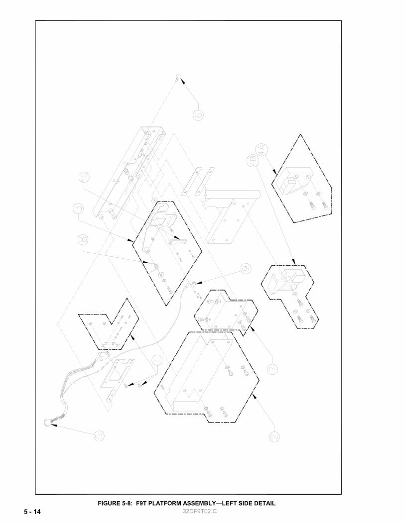
32DF9T02.C 5 - 14FIGURE 5-8: F9T PLATFORM ASSEMBLY—LEFT SIDE DETAIL
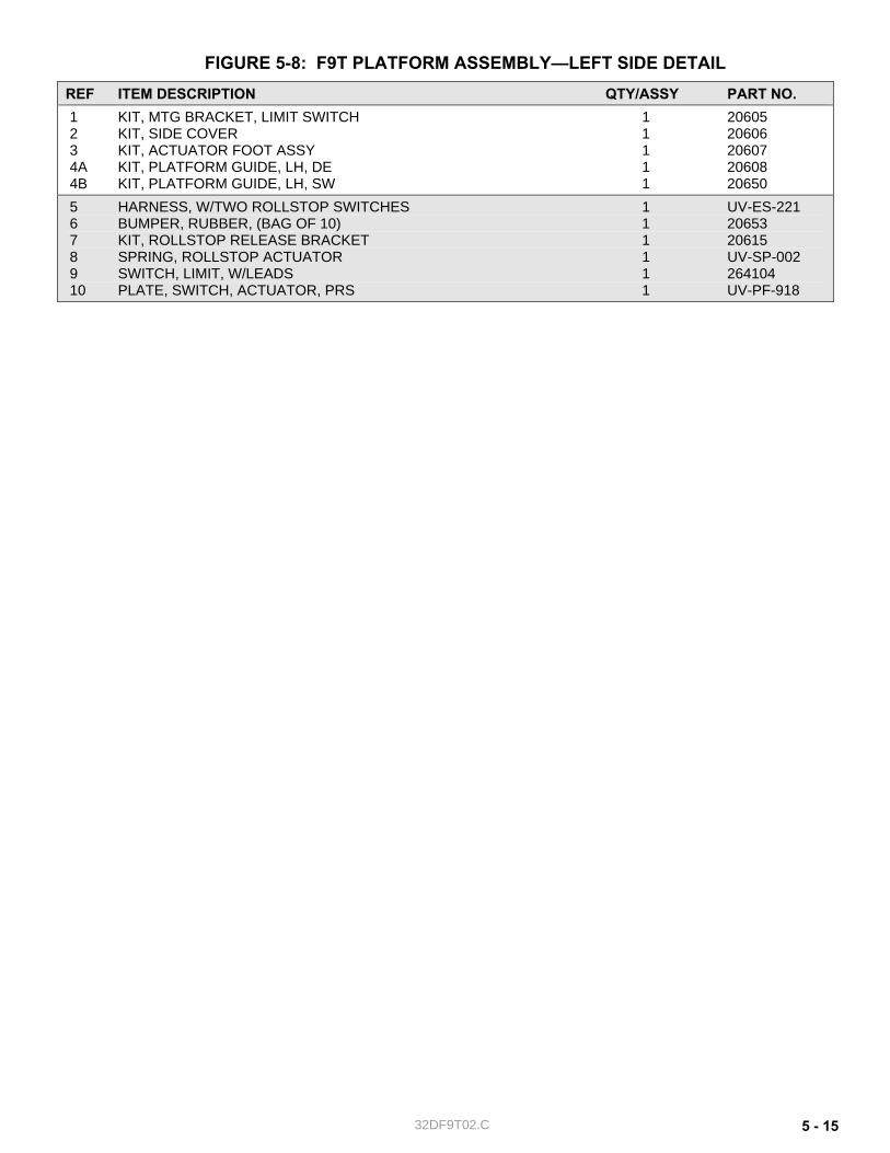
32DF9T02.C 5 - 15
FIGURE 5-8: F9T PLATFORM ASSEMBLY—LEFT SIDE DETAIL REF ITEM DESCRIPTION QTY/ASSY PART NO. 1 KIT, MTG BRACKET, LIMIT SWITCH 1 20605 2 KIT, SIDE COVER 1 20606 3 KIT, ACTUATOR FOOT ASSY 1 20607 4A KIT, PLATFORM GUIDE, LH, DE 1 20608 4B KIT, PLATFORM GUIDE, LH, SW 1 20650 5 HARNESS, W/TWO ROLLSTOP SWITCHES 1 UV-ES-221 6 BUMPER, RUBBER, (BAG OF 10) 1 20653 7 KIT, ROLLSTOP RELEASE BRACKET 1 20615 8 SPRING, ROLLSTOP ACTUATOR 1 UV-SP-002 9 SWITCH, LIMIT, W/LEADS 1 264104 10 PLATE, SWITCH, ACTUATOR, PRS 1 UV-PF-918
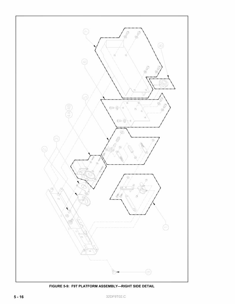
32DF9T02.C 5 - 16
FIGURE 5-9: F9T PLATFORM ASSEMBLY—RIGHT SIDE DETAIL
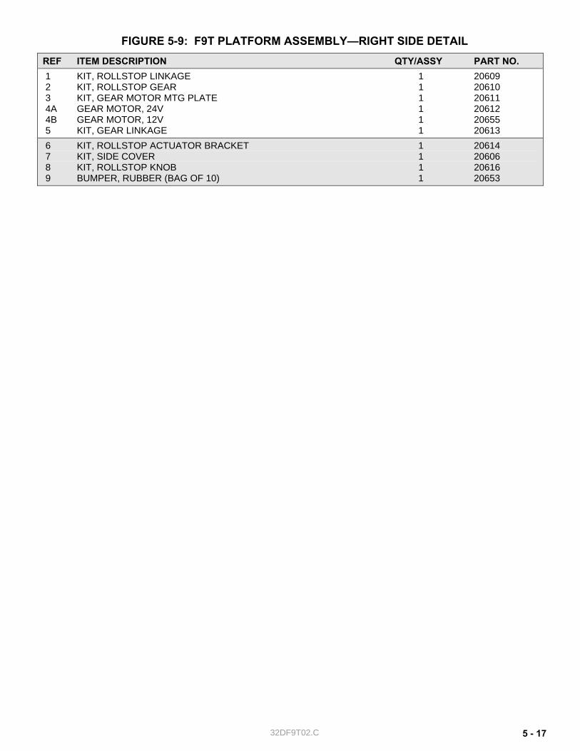
32DF9T02.C 5 - 17
FIGURE 5-9: F9T PLATFORM ASSEMBLY—RIGHT SIDE DETAIL REF ITEM DESCRIPTION QTY/ASSY PART NO. 1 KIT, ROLLSTOP LINKAGE 1 20609 2 KIT, ROLLSTOP GEAR 1 20610 3 KIT, GEAR MOTOR MTG PLATE 1 20611 4A GEAR MOTOR, 24V 1 20612 4B GEAR MOTOR, 12V 1 20655 5 KIT, GEAR LINKAGE 1 20613 6 KIT, ROLLSTOP ACTUATOR BRACKET 1 20614 7 KIT, SIDE COVER 1 20606 8 KIT, ROLLSTOP KNOB 1 20616 9 BUMPER, RUBBER (BAG OF 10) 1 20653
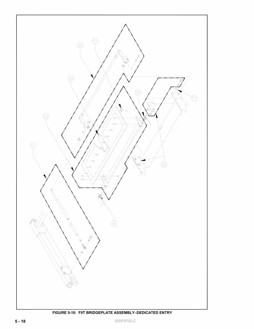
32DF9T02.C 5 - 18
FIGURE 5-10: F9T BRIDGEPLATE ASSEMBLY–DEDICATED ENTRY
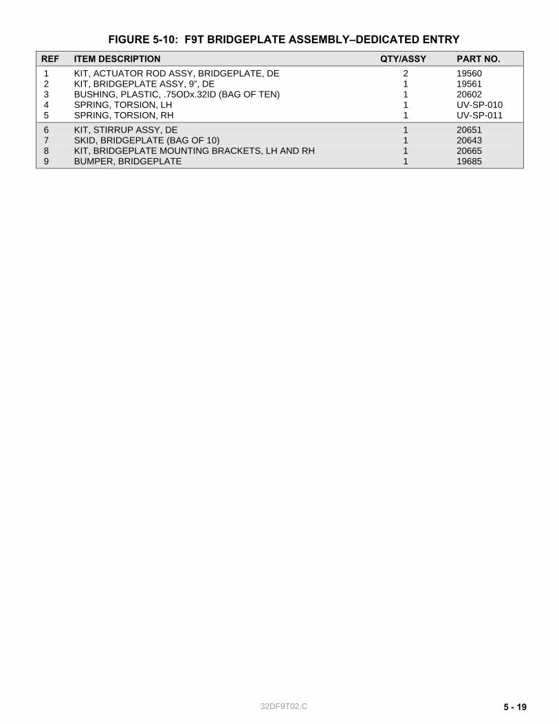
32DF9T02.C 5 - 19
FIGURE 5-10: F9T BRIDGEPLATE ASSEMBLY–DEDICATED ENTRY REF ITEM DESCRIPTION QTY/ASSY PART NO. 1 KIT, ACTUATOR ROD ASSY, BRIDGEPLATE, DE 2 19560 2 KIT, BRIDGEPLATE ASSY, 9”, DE 1 19561 3 BUSHING, PLASTIC, .75ODx.32ID (BAG OF TEN) 1 20602 4 SPRING, TORSION, LH 1 UV-SP-010 5 SPRING, TORSION, RH 1 UV-SP-011 6 KIT, STIRRUP ASSY, DE 1 20651 7 SKID, BRIDGEPLATE (BAG OF 10) 1 20643 8 KIT, BRIDGEPLATE MOUNTING BRACKETS, LH AND RH 1 20665 9 BUMPER, BRIDGEPLATE 1 19685
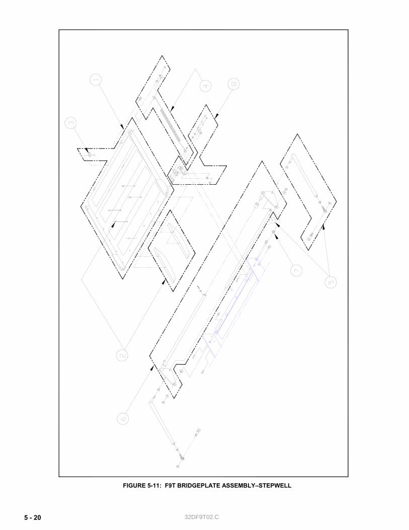
32DF9T02.C 5 - 20
FIGURE 5-11: F9T BRIDGEPLATE ASSEMBLY–STEPWELL

32DF9T02.C 5 - 21
FIGURE 5-11: F9T BRIDGEPLATE ASSEMBLY–STEPWELL REF ITEM DESCRIPTION QTY/ASSY PART NO. 1A KIT, BRIDGEPLATE ASSY, SW (F9T-SG001) 1 20641 1B KIT, BRIDGEPLATE ASSY, 23” SPAN (F9T-SG002, F9T-SG004, F9T-SG005) 1 F9-0314 2 KIT, SKID, BRIDGEPLATE, SW 1 20642 3 BUMPER PAD, BRIDGEGPLATE, (BAG OF 10) 1 20643 4 KIT, SPRING ASSY, SW 2 20644 5 KIT, LINK ARM ASSY, SW 2 20645 6 KIT, STIRRUP ASSY, SW 1 20646 7 BUSHING, STIRRUP PIVOT, (BAG OF 10) 1 20647 8 KIT, PIVOT LINKAGE, SW 2 20652
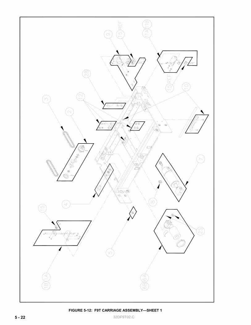
32DF9T02.C 5 - 22
FIGURE 5-12: F9T CARRIAGE ASSEMBLY—SHEET 1
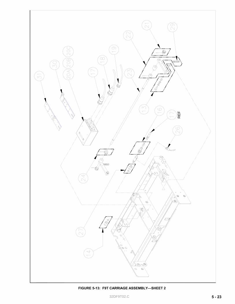
32DF9T02.C 5 - 23
FIGURE 5-13: F9T CARRIAGE ASSEMBLY—SHEET 2
RE
F
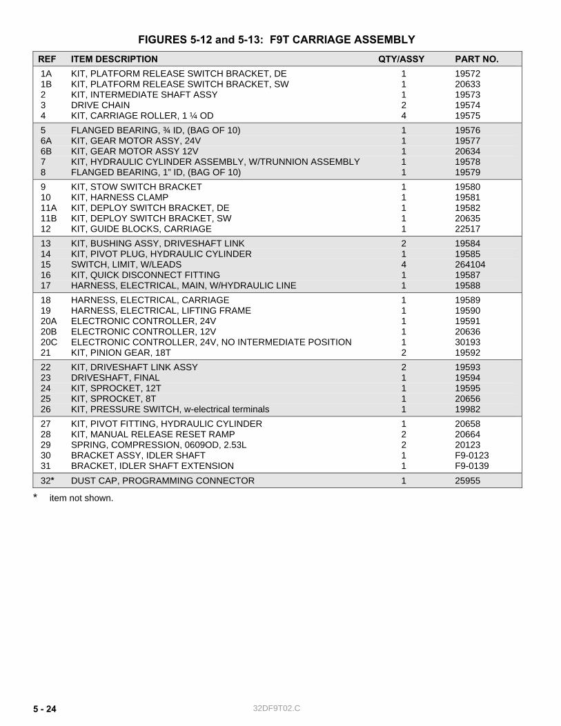
32DF9T02.C 5 - 24
FIGURES 5-12 and 5-13: F9T CARRIAGE ASSEMBLY REF ITEM DESCRIPTION QTY/ASSY PART NO. 1A KIT, PLATFORM RELEASE SWITCH BRACKET, DE 1 19572 1B KIT, PLATFORM RELEASE SWITCH BRACKET, SW 1 20633 2 KIT, INTERMEDIATE SHAFT ASSY 1 19573 3 DRIVE CHAIN 2 19574 4 KIT, CARRIAGE ROLLER, 1 ¼ OD 4 19575 5 FLANGED BEARING, ¾ ID, (BAG OF 10) 1 19576 6A KIT, GEAR MOTOR ASSY, 24V 1 19577 6B KIT, GEAR MOTOR ASSY 12V 1 20634 7 KIT, HYDRAULIC CYLINDER ASSEMBLY, W/TRUNNION ASSEMBLY 1 19578 8 FLANGED BEARING, 1” ID, (BAG OF 10) 1 19579 9 KIT, STOW SWITCH BRACKET 1 19580 10 KIT, HARNESS CLAMP 1 19581 11A KIT, DEPLOY SWITCH BRACKET, DE 1 19582 11B KIT, DEPLOY SWITCH BRACKET, SW 1 20635 12 KIT, GUIDE BLOCKS, CARRIAGE 1 22517 13 KIT, BUSHING ASSY, DRIVESHAFT LINK 2 19584 14 KIT, PIVOT PLUG, HYDRAULIC CYLINDER 1 19585 15 SWITCH, LIMIT, W/LEADS 4 264104 16 KIT, QUICK DISCONNECT FITTING 1 19587 17 HARNESS, ELECTRICAL, MAIN, W/HYDRAULIC LINE 1 19588 18 HARNESS, ELECTRICAL, CARRIAGE 1 19589 19 HARNESS, ELECTRICAL, LIFTING FRAME 1 19590 20A ELECTRONIC CONTROLLER, 24V 1 19591 20B ELECTRONIC CONTROLLER, 12V 1 20636 20C ELECTRONIC CONTROLLER, 24V, NO INTERMEDIATE POSITION 1 30193 21 KIT, PINION GEAR, 18T 2 19592 22 KIT, DRIVESHAFT LINK ASSY 2 19593 23 DRIVESHAFT, FINAL 1 19594 24 KIT, SPROCKET, 12T 1 19595 25 KIT, SPROCKET, 8T 1 20656 26 KIT, PRESSURE SWITCH, w-electrical terminals 1 19982 27 KIT, PIVOT FITTING, HYDRAULIC CYLINDER 1 20658 28 KIT, MANUAL RELEASE RESET RAMP 2 20664 29 SPRING, COMPRESSION, 0609OD, 2.53L 2 20123 30 BRACKET ASSY, IDLER SHAFT 1 F9-0123 31 BRACKET, IDLER SHAFT EXTENSION 1 F9-0139 32* DUST CAP, PROGRAMMING CONNECTOR 1 25955
* item not shown.

32DF9T02.C 5 - 25
This page intentionally left blank.

32DF9T02.C 5 - 26
FIGURE 5-14: F9T PENDANT ASSEMBLY

32DF9T02.C 5 - 27
FIGURE 5-14: F9T PENDANT ASSEMBLY REF ITEM DESCRIPTION QTY/ASSY PART NO. 1A KIT, MOUNTING BRACKET, PENDANT, SW 1 01118 1B KIT, MOUNTING BRACKET, PENDANT, DE 1 20637 2A PENDANT, 24V, (F9T-DE005, DE007, DE021, DE025, DE026, DE033, DS002 1 F9-0373 DS003, SG001, SG004, SG005) 2B PENDANT, 24V, (F9T-DE001, DE002, DE003, DE004) 1 206383 EXTENSION, PENDANT, 62” 1 19818 EXTENSION, HARNESS, PENDANT TO PULLBOX 1 F9-0395 4A SWITCH, SPDT ROCKER, WHITE 1 264115 4B SWITCH, SPDT ROCKER, RED 1 20103
-RETURN TO PREVIOUS CHAPTER-