Embed Size (px)
Citation preview
Recommendation for Space Data System Standards
BLUE BOOK
TM SPACE DATA LINK PROTOCOL
RECOMMENDED STANDARD
CCSDS 132.0-B-2
September 2015
Recommendation for Space Data System Standards
TM SPACE DATA LINK PROTOCOL
RECOMMENDED STANDARD
CCSDS 132.0-B-2
BLUE BOOK September 2015

CCSDS RECOMMENDED STANDARD FOR TM SPACE DATA LINK PROTOCOL
CCSDS 132.0-B-2 Page i September 2015
AUTHORITY
Issue: Recommended Standard, Issue 2 Date: September 2015 Location: Washington, DC, USA
This document has been approved for publication by the Management Council of the Consultative Committee for Space Data Systems (CCSDS) and represents the consensus technical agreement of the participating CCSDS Member Agencies. The procedure for review and authorization of CCSDS documents is detailed in Organization and Processes for the Consultative Committee for Space Data Systems (CCSDS A02.1-Y-4), and the record of Agency participation in the authorization of this document can be obtained from the CCSDS Secretariat at the e-mail address below. This document is published and maintained by:
CCSDS Secretariat National Aeronautics and Space Administration Washington, DC, USA E-mail: [email protected]

CCSDS RECOMMENDED STANDARD FOR TM SPACE DATA LINK PROTOCOL
CCSDS 132.0-B-2 Page ii September 2015
STATEMENT OF INTENT
The Consultative Committee for Space Data Systems (CCSDS) is an organization officially established by the management of its members. The Committee meets periodically to address data systems problems that are common to all participants, and to formulate sound technical solutions to these problems. Inasmuch as participation in the CCSDS is completely voluntary, the results of Committee actions are termed Recommended Standards and are not considered binding on any Agency.
This Recommended Standard is issued by, and represents the consensus of, the CCSDS members. Endorsement of this Recommendation is entirely voluntary. Endorsement, however, indicates the following understandings:
o Whenever a member establishes a CCSDS-related standard, this standard will be in accord with the relevant Recommended Standard. Establishing such a standard does not preclude other provisions which a member may develop.
o Whenever a member establishes a CCSDS-related standard, that member will provide other CCSDS members with the following information:
-- The standard itself.
-- The anticipated date of initial operational capability.
-- The anticipated duration of operational service.
o Specific service arrangements shall be made via memoranda of agreement. Neither this Recommended Standard nor any ensuing standard is a substitute for a memorandum of agreement.
No later than five years from its date of issuance, this Recommended Standard will be reviewed by the CCSDS to determine whether it should: (1) remain in effect without change; (2) be changed to reflect the impact of new technologies, new requirements, or new directions; or (3) be retired or canceled.
In those instances when a new version of a Recommended Standard is issued, existing CCSDS-related member standards and implementations are not negated or deemed to be non-CCSDS compatible. It is the responsibility of each member to determine when such standards or implementations are to be modified. Each member is, however, strongly encouraged to direct planning for its new standards and implementations towards the later version of the Recommended Standard.
CCSDS RECOMMENDED STANDARD FOR TM SPACE DATA LINK PROTOCOL
CCSDS 132.0-B-2 Page iii September 2015
FOREWORD
This document is a technical Recommendation for use in developing flight and ground systems for space missions and has been prepared by the Consultative Committee for Space Data Systems (CCSDS). The TM Space Data Link Protocol described herein is intended for missions that are cross-supported between Agencies of the CCSDS.
Attention is drawn to the possibility that some of the elements of this document may be the subject of patent rights. CCSDS has processes for identifying patent issues and for securing from the patent holder agreement that all licensing policies are reasonable and non-discriminatory. However, CCSDS does not have a patent law staff, and CCSDS shall not be held responsible for identifying any or all such patent rights.
Through the process of normal evolution, it is expected that expansion, deletion, or modification of this document may occur. This Recommended Standard is therefore subject to CCSDS document management and change control procedures, which are defined in Organization and Processes for the Consultative Committee for Space Data Systems (CCSDS A02.1-Y-4). Current versions of CCSDS documents are maintained at the CCSDS Web site:
http://www.ccsds.org/
Questions relating to the contents or status of this document should be sent to the CCSDS Secretariat at the e-mail address indicated on page i.
CCSDS RECOMMENDED STANDARD FOR TM SPACE DATA LINK PROTOCOL
CCSDS 132.0-B-2 Page iv September 2015
At time of publication, the active Member and Observer Agencies of the CCSDS were:
Member Agencies – Agenzia Spaziale Italiana (ASI)/Italy. – Canadian Space Agency (CSA)/Canada. – Centre National d’Etudes Spatiales (CNES)/France. – China National Space Administration (CNSA)/People’s Republic of China. – Deutsches Zentrum für Luft- und Raumfahrt (DLR)/Germany. – European Space Agency (ESA)/Europe. – Federal Space Agency (FSA)/Russian Federation. – Instituto Nacional de Pesquisas Espaciais (INPE)/Brazil. – Japan Aerospace Exploration Agency (JAXA)/Japan. – National Aeronautics and Space Administration (NASA)/USA. – UK Space Agency/United Kingdom.
Observer Agencies – Austrian Space Agency (ASA)/Austria. – Belgian Federal Science Policy Office (BFSPO)/Belgium. – Central Research Institute of Machine Building (TsNIIMash)/Russian Federation. – China Satellite Launch and Tracking Control General, Beijing Institute of Tracking and
Telecommunications Technology (CLTC/BITTT)/China. – Chinese Academy of Sciences (CAS)/China. – Chinese Academy of Space Technology (CAST)/China. – Commonwealth Scientific and Industrial Research Organization (CSIRO)/Australia. – Danish National Space Center (DNSC)/Denmark. – Departamento de Ciência e Tecnologia Aeroespacial (DCTA)/Brazil. – Electronics and Telecommunications Research Institute (ETRI)/Korea. – European Organization for the Exploitation of Meteorological Satellites (EUMETSAT)/Europe. – European Telecommunications Satellite Organization (EUTELSAT)/Europe. – Geo-Informatics and Space Technology Development Agency (GISTDA)/Thailand. – Hellenic National Space Committee (HNSC)/Greece. – Indian Space Research Organization (ISRO)/India. – Institute of Space Research (IKI)/Russian Federation. – KFKI Research Institute for Particle & Nuclear Physics (KFKI)/Hungary. – Korea Aerospace Research Institute (KARI)/Korea. – Ministry of Communications (MOC)/Israel. – National Institute of Information and Communications Technology (NICT)/Japan. – National Oceanic and Atmospheric Administration (NOAA)/USA. – National Space Agency of the Republic of Kazakhstan (NSARK)/Kazakhstan. – National Space Organization (NSPO)/Chinese Taipei. – Naval Center for Space Technology (NCST)/USA. – Scientific and Technological Research Council of Turkey (TUBITAK)/Turkey. – South African National Space Agency (SANSA)/Republic of South Africa. – Space and Upper Atmosphere Research Commission (SUPARCO)/Pakistan. – Swedish Space Corporation (SSC)/Sweden. – Swiss Space Office (SSO)/Switzerland. – United States Geological Survey (USGS)/USA.
CCSDS RECOMMENDED STANDARD FOR TM SPACE DATA LINK PROTOCOL
CCSDS 132.0-B-2 Page v September 2015
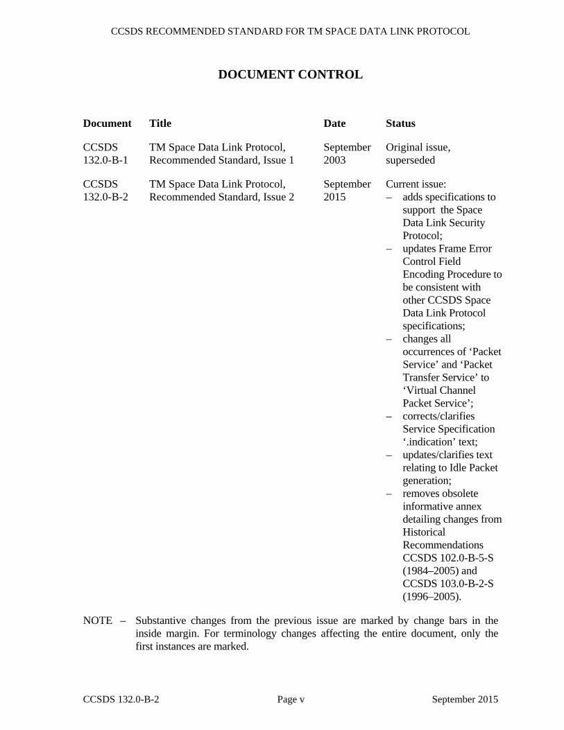
DOCUMENT CONTROL
Document Title Date Status
CCSDS 132.0-B-1
TM Space Data Link Protocol, Recommended Standard, Issue 1
September 2003
Original issue, superseded
CCSDS 132.0-B-2
TM Space Data Link Protocol, Recommended Standard, Issue 2
September 2015
Current issue: – adds specifications to
support the Space Data Link Security Protocol;
– updates Frame Error Control Field Encoding Procedure to be consistent with other CCSDS Space Data Link Protocol specifications;
– changes all occurrences of ‘Packet Service’ and ‘Packet Transfer Service’ to ‘Virtual Channel Packet Service’;
– corrects/clarifies Service Specification ‘.indication’ text;
– updates/clarifies text relating to Idle Packet generation;
– removes obsolete informative annex detailing changes from Historical Recommendations CCSDS 102.0-B-5-S (1984–2005) and CCSDS 103.0-B-2-S (1996–2005).
NOTE – Substantive changes from the previous issue are marked by change bars in the inside margin. For terminology changes affecting the entire document, only the first instances are marked.

CCSDS RECOMMENDED STANDARD FOR TM SPACE DATA LINK PROTOCOL
CCSDS 132.0-B-2 Page vi September 2015
CONTENTS
Section Page
1 INTRODUCTION .......................................................................................................... 1-1 1.1 PURPOSE ............................................................................................................... 1-1 1.2 SCOPE .................................................................................................................... 1-1 1.3 APPLICABILITY ................................................................................................... 1-1 1.4 RATIONALE .......................................................................................................... 1-2 1.5 DOCUMENT STRUCTURE ................................................................................. 1-2 1.6 CONVENTIONS AND DEFINITIONS................................................................. 1-2 1.7 REFERENCES ....................................................................................................... 1-6
2 OVERVIEW ................................................................................................................... 2-1
2.1 CONCEPT OF TM SPACE DATA LINK PROTOCOL ....................................... 2-1 2.2 OVERVIEW OF SERVICES ................................................................................. 2-4 2.3 OVERVIEW OF FUNCTIONS ............................................................................ 2-12 2.4 SERVICES ASSUMED FROM LOWER LAYERS ........................................... 2-14
3 SERVICE DEFINITION ............................................................................................... 3-1
3.1 OVERVIEW ........................................................................................................... 3-1 3.2 SOURCE DATA ..................................................................................................... 3-1 3.3 VIRTUAL CHANNEL PACKET (VCP) SERVICE ............................................. 3-4 3.4 VIRTUAL CHANNEL ACCESS (VCA) SERVICE ............................................. 3-8 3.5 VIRTUAL CHANNEL FRAME SECONDARY HEADER (VC_FSH)
SERVICE .............................................................................................................. 3-12 3.6 VIRTUAL CHANNEL OPERATIONAL CONTROL FIELD (VC_OCF)
SERVICE .............................................................................................................. 3-15 3.7 VIRTUAL CHANNEL FRAME (VCF) SERVICE ............................................. 3-18 3.8 MASTER CHANNEL FRAME SECONDARY HEADER (MC_FSH)
SERVICE .............................................................................................................. 3-21 3.9 MASTER CHANNEL OPERATIONAL CONTROL FIELD (MC_OCF)
SERVICE .............................................................................................................. 3-24 3.10 MASTER CHANNEL FRAME (MCF) SERVICE .............................................. 3-27
4 PROTOCOL SPECIFICATION WITHOUT SDLS OPTION ................................. 4-1
4.1 PROTOCOL DATA UNIT ..................................................................................... 4-1 4.2 PROTOCOL PROCEDURES AT THE SENDING END .................................... 4-15 4.3 PROTOCOL PROCEDURES AT THE RECEIVING END ................................ 4-22
CCSDS RECOMMENDED STANDARD FOR TM SPACE DATA LINK PROTOCOL
CCSDS 132.0-B-2 Page vii September 2015
CONTENTS (continued)
Section Page
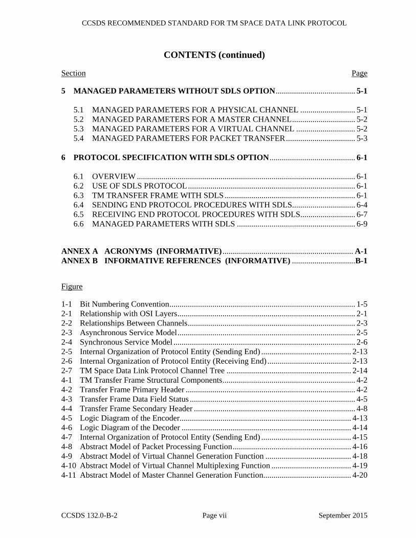
5 MANAGED PARAMETERS WITHOUT SDLS OPTION ....................................... 5-1 5.1 MANAGED PARAMETERS FOR A PHYSICAL CHANNEL ........................... 5-1 5.2 MANAGED PARAMETERS FOR A MASTER CHANNEL ............................... 5-2 5.3 MANAGED PARAMETERS FOR A VIRTUAL CHANNEL ............................. 5-2 5.4 MANAGED PARAMETERS FOR PACKET TRANSFER .................................. 5-3
6 PROTOCOL SPECIFICATION WITH SDLS OPTION .......................................... 6-1
6.1 OVERVIEW ........................................................................................................... 6-1 6.2 USE OF SDLS PROTOCOL .................................................................................. 6-1 6.3 TM TRANSFER FRAME WITH SDLS ................................................................ 6-1 6.4 SENDING END PROTOCOL PROCEDURES WITH SDLS............................... 6-4 6.5 RECEIVING END PROTOCOL PROCEDURES WITH SDLS........................... 6-7 6.6 MANAGED PARAMETERS WITH SDLS .......................................................... 6-9
ANNEX A ACRONYMS (INFORMATIVE) ................................................................ A-1 ANNEX B INFORMATIVE REFERENCES (INFORMATIVE) ...............................B-1
Figure
1-1 Bit Numbering Convention ........................................................................................... 1-5 2-1 Relationship with OSI Layers ....................................................................................... 2-1 2-2 Relationships Between Channels .................................................................................. 2-3 2-3 Asynchronous Service Model ....................................................................................... 2-5 2-4 Synchronous Service Model ......................................................................................... 2-6 2-5 Internal Organization of Protocol Entity (Sending End) ............................................ 2-13 2-6 Internal Organization of Protocol Entity (Receiving End) ......................................... 2-13 2-7 TM Space Data Link Protocol Channel Tree ............................................................. 2-14 4-1 TM Transfer Frame Structural Components ................................................................. 4-2 4-2 Transfer Frame Primary Header ................................................................................... 4-2 4-3 Transfer Frame Data Field Status ................................................................................. 4-5 4-4 Transfer Frame Secondary Header ............................................................................... 4-8 4-5 Logic Diagram of the Encoder.................................................................................... 4-13 4-6 Logic Diagram of the Decoder ................................................................................... 4-14 4-7 Internal Organization of Protocol Entity (Sending End) ............................................ 4-15 4-8 Abstract Model of Packet Processing Function .......................................................... 4-16 4-9 Abstract Model of Virtual Channel Generation Function .......................................... 4-18 4-10 Abstract Model of Virtual Channel Multiplexing Function ....................................... 4-19 4-11 Abstract Model of Master Channel Generation Function........................................... 4-20
CCSDS RECOMMENDED STANDARD FOR TM SPACE DATA LINK PROTOCOL
CCSDS 132.0-B-2 Page viii September 2015
CONTENTS (continued)
Figure Page
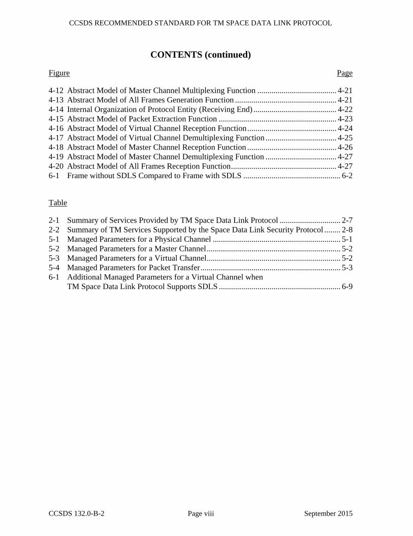
4-12 Abstract Model of Master Channel Multiplexing Function ....................................... 4-21 4-13 Abstract Model of All Frames Generation Function .................................................. 4-21 4-14 Internal Organization of Protocol Entity (Receiving End) ......................................... 4-22 4-15 Abstract Model of Packet Extraction Function .......................................................... 4-23 4-16 Abstract Model of Virtual Channel Reception Function ............................................ 4-24 4-17 Abstract Model of Virtual Channel Demultiplexing Function ................................... 4-25 4-18 Abstract Model of Master Channel Reception Function ............................................ 4-26 4-19 Abstract Model of Master Channel Demultiplexing Function ................................... 4-27 4-20 Abstract Model of All Frames Reception Function .................................................... 4-27 6-1 Frame without SDLS Compared to Frame with SDLS ................................................ 6-2
Table
2-1 Summary of Services Provided by TM Space Data Link Protocol .............................. 2-7 2-2 Summary of TM Services Supported by the Space Data Link Security Protocol ........ 2-8 5-1 Managed Parameters for a Physical Channel ............................................................... 5-1 5-2 Managed Parameters for a Master Channel .................................................................. 5-2 5-3 Managed Parameters for a Virtual Channel .................................................................. 5-2 5-4 Managed Parameters for Packet Transfer ..................................................................... 5-3 6-1 Additional Managed Parameters for a Virtual Channel when
TM Space Data Link Protocol Supports SDLS ............................................................ 6-9
CCSDS RECOMMENDED STANDARD FOR TM SPACE DATA LINK PROTOCOL
CCSDS 132.0-B-2 Page 1-1 September 2015
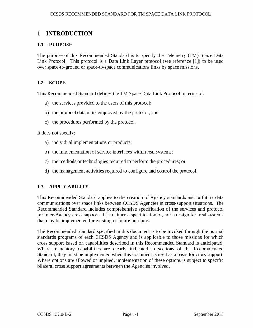
1 INTRODUCTION
1.1 PURPOSE
The purpose of this Recommended Standard is to specify the Telemetry (TM) Space Data Link Protocol. This protocol is a Data Link Layer protocol (see reference [1]) to be used over space-to-ground or space-to-space communications links by space missions.
1.2 SCOPE
This Recommended Standard defines the TM Space Data Link Protocol in terms of:
a) the services provided to the users of this protocol;
b) the protocol data units employed by the protocol; and
c) the procedures performed by the protocol.
It does not specify:
a) individual implementations or products;
b) the implementation of service interfaces within real systems;
c) the methods or technologies required to perform the procedures; or
d) the management activities required to configure and control the protocol.
1.3 APPLICABILITY
This Recommended Standard applies to the creation of Agency standards and to future data communications over space links between CCSDS Agencies in cross-support situations. The Recommended Standard includes comprehensive specification of the services and protocol for inter-Agency cross support. It is neither a specification of, nor a design for, real systems that may be implemented for existing or future missions.
The Recommended Standard specified in this document is to be invoked through the normal standards programs of each CCSDS Agency and is applicable to those missions for which cross support based on capabilities described in this Recommended Standard is anticipated. Where mandatory capabilities are clearly indicated in sections of the Recommended Standard, they must be implemented when this document is used as a basis for cross support. Where options are allowed or implied, implementation of these options is subject to specific bilateral cross support agreements between the Agencies involved.
CCSDS RECOMMENDED STANDARD FOR TM SPACE DATA LINK PROTOCOL
CCSDS 132.0-B-2 Page 1-2 September 2015
1.4 RATIONALE
The CCSDS believes it is important to document the rationale underlying the recommendations chosen, so that future evaluations of proposed changes or improvements will not lose sight of previous decisions.
1.5 DOCUMENT STRUCTURE
This document is divided into six numbered sections and two annexes:
– Section 1 presents the purpose, scope, applicability and rationale of this Recommended Standard and lists the conventions, definitions, and references used throughout the Recommended Standard.
– Section 2 provides an overview of the TM Space Data Link Protocol.
– Section 3 defines the services provided by the protocol entity.
– Section 4 specifies the protocol data units and procedures employed by the protocol entity.
– Section 5 specifies the managed parameters used by the protocol entity.
– Section 6 specifies the protocol entity with support for the Space Data Link Security Protocol.
– Annex A lists all acronyms used within this document.
– Annex B provides a list of informative references.
1.6 CONVENTIONS AND DEFINITIONS
1.6.1 DEFINITIONS
1.6.1.1 Definitions from the Open Systems Interconnection (OSI) Basic Reference Model
This Recommended Standard makes use of a number of terms defined in reference [1]. The use of those terms in this Recommended Standard is to be understood in a generic sense, i.e., in the sense that those terms are generally applicable to any of a variety of technologies that provide for the exchange of information between real systems. Those terms are:
a) blocking;
b) connection;
c) Data Link Layer;
d) entity;
CCSDS RECOMMENDED STANDARD FOR TM SPACE DATA LINK PROTOCOL
CCSDS 132.0-B-2 Page 1-3 September 2015
e) flow control;
f) Network Layer;
g) peer entities;
h) Physical Layer;
i) protocol control information;
j) protocol data unit;
k) real system;
l) segmenting;
m) service;
n) Service Access Point (SAP);
o) SAP address;
p) service data unit.
1.6.1.2 Definitions from OSI Service Definition Conventions
This Recommended Standard makes use of a number of terms defined in reference [2]. The use of those terms in this Recommended Standard is to be understood in a generic sense, i.e., in the sense that those terms are generally applicable to any of a variety of technologies that provide for the exchange of information between real systems. Those terms are:
a) confirmation;
b) indication;
c) primitive;
d) request;
e) response;
f) service provider;
g) service user.
1.6.1.3 Terms Defined in This Recommended Standard
For the purposes of this Recommended Standard, the following definitions also apply. Many other terms that pertain to specific items are defined in the appropriate sections.
aperiodic: not periodic (see below).
CCSDS RECOMMENDED STANDARD FOR TM SPACE DATA LINK PROTOCOL
CCSDS 132.0-B-2 Page 1-4 September 2015
asynchronous: not synchronous (see below).
delimited: having a known (and finite) length; applies to data in the context of data handling.
Mission Phase: a period of a mission during which specified communications characteristics are fixed. The transition between two consecutive Mission Phases may cause an interruption of the communications services.
periodic: of or pertaining to a sequence of events in which each event occurs at a fixed time interval (within specified tolerance) after the previous event in the sequence.
Physical Channel: a stream of bits transferred over a space link in a single direction.
space link: a communications link between a spacecraft and its associated ground system or between two spacecraft. A space link consists of one or more Physical Channels in one or both directions.
synchronous: of or pertaining to a sequence of events occurring in a fixed time relationship (within specified tolerance) to another sequence of events. It should be noted that ‘synchronous’ does not necessarily imply ‘periodic’ or ‘constant rate’.
(TM) Transfer Frame: The protocol data unit of the Telemetry (TM) Space Data Link Protocol.
1.6.2 NOMENCLATURE
1.6.2.1 Normative Text
The following conventions apply for the normative specifications in this Recommended Standard:
a) the words ‘shall’ and ‘must’ imply a binding and verifiable specification;
b) the word ‘should’ implies an optional, but desirable, specification;
c) the word ‘may’ implies an optional specification;
d) the words ‘is’, ‘are’, and ‘will’ imply statements of fact.
NOTE – These conventions do not imply constraints on diction in text that is clearly informative in nature.
1.6.2.2 Informative Text
In the normative sections of this document, informative text is set off from the normative specifications either in notes or under one of the following subsection headings:
CCSDS RECOMMENDED STANDARD FOR TM SPACE DATA LINK PROTOCOL
CCSDS 132.0-B-2 Page 1-5 September 2015
– Overview;
– Background;
– Rationale;
– Discussion.
1.6.3 CONVENTIONS
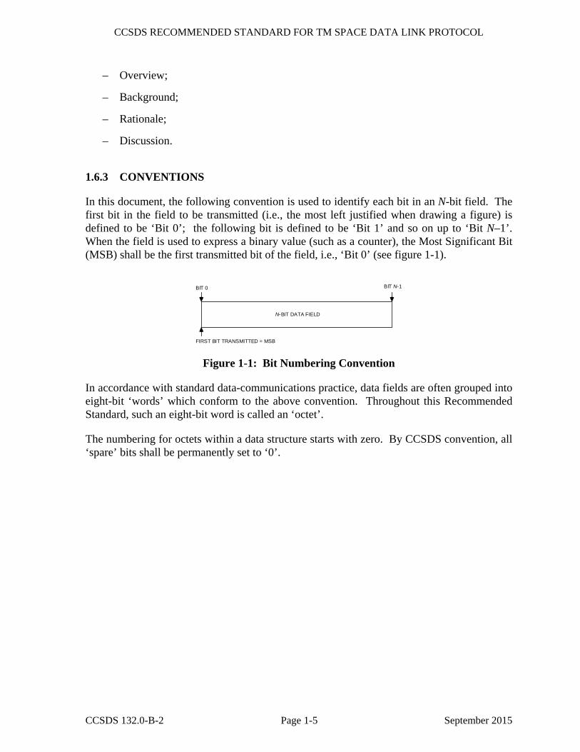
In this document, the following convention is used to identify each bit in an N-bit field. The first bit in the field to be transmitted (i.e., the most left justified when drawing a figure) is defined to be ‘Bit 0’; the following bit is defined to be ‘Bit 1’ and so on up to ‘Bit N–1’. When the field is used to express a binary value (such as a counter), the Most Significant Bit (MSB) shall be the first transmitted bit of the field, i.e., ‘Bit 0’ (see figure 1-1).
N-BIT DATA FIELD
BIT 0 BIT N-1
FIRST BIT TRANSMITTED = MSB
Figure 1-1: Bit Numbering Convention
In accordance with standard data-communications practice, data fields are often grouped into eight-bit ‘words’ which conform to the above convention. Throughout this Recommended Standard, such an eight-bit word is called an ‘octet’.
The numbering for octets within a data structure starts with zero. By CCSDS convention, all ‘spare’ bits shall be permanently set to ‘0’.
CCSDS RECOMMENDED STANDARD FOR TM SPACE DATA LINK PROTOCOL
CCSDS 132.0-B-2 Page 1-6 September 2015
1.7 REFERENCES
The following publications contain provisions which, through reference in this text, constitute provisions of this document. At the time of publication, the editions indicated were valid. All publications are subject to revision, and users of this document are encouraged to investigate the possibility of applying the most recent editions of the publications indicated below. The CCSDS Secretariat maintains a register of currently valid CCSDS publications.
[1] Information Technology—Open Systems Interconnection—Basic Reference Model: The Basic Model. 2nd ed. International Standard, ISO/IEC 7498-1:1994. Geneva: ISO, 1994.
[2] Information Technology—Open Systems Interconnection—Basic Reference Model—Conventions for the Definition of OSI Services. International Standard, ISO/IEC 10731:1994. Geneva: ISO, 1994.
[3] TM Synchronization and Channel Coding. Issue 2. Recommendation for Space Data System Standards (Blue Book), CCSDS 131.0-B-2. Washington, D.C.: CCSDS, August 2011.
[4] Flexible Advanced Coding and Modulation Scheme for High Rate Telemetry Applications. Issue 1. Recommendation for Space Data System Standards (Blue Book), CCSDS 131.2-B-1. Washington, D.C.: CCSDS, March 2012.
[5] CCSDS Space Link Protocols over ETSI DVB-S2 Standard. Issue 1. Recommendation for Space Data System Standards (Blue Book), CCSDS 131.3-B-1. Washington, D.C.: CCSDS, March 2013.
[6] “Packet Version Number.” Space Assigned Number Authority. http://sanaregistry.org/r/packet_version_number/.
[7] CCSDS Global Spacecraft Identification Field Code Assignment Control Procedures. Issue 6. Recommendation for Space Data System Standards (Blue Book), CCSDS 320.0-B-6. Washington, D.C.: CCSDS, October 2013.
[8] Space Packet Protocol. Issue 1. Recommendation for Space Data System Standards (Blue Book), CCSDS 133.0-B-1. Washington, D.C.: CCSDS, September 2003.
[9] Encapsulation Service. Issue 2. Recommendation for Space Data System Standards (Blue Book), CCSDS 133.1-B-2. Washington, D.C.: CCSDS, October 2009.
[10] Space Data Link Security Protocol. Issue 1. Recommendation for Space Data System Standards (Blue Book), CCSDS 355.0-B-1. Washington, D.C.: CCSDS, September 2015.
NOTE – Informative references are listed in annex B.
CCSDS RECOMMENDED STANDARD FOR TM SPACE DATA LINK PROTOCOL
CCSDS 132.0-B-2 Page 2-1 September 2015
2 OVERVIEW
2.1 CONCEPT OF TM SPACE DATA LINK PROTOCOL
2.1.1 ARCHITECTURE
The TM Space Data Link Protocol is a Data Link Layer protocol (see reference [1]) to be used by space missions. This protocol has been designed to meet the requirements of space missions for efficient transfer of space application data of various types and characteristics over space-to-ground or space-to-space communications links (hereafter called space links).
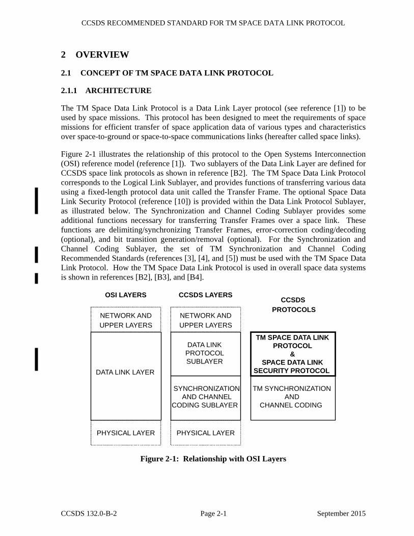
Figure 2-1 illustrates the relationship of this protocol to the Open Systems Interconnection (OSI) reference model (reference [1]). Two sublayers of the Data Link Layer are defined for CCSDS space link protocols as shown in reference [B2]. The TM Space Data Link Protocol corresponds to the Logical Link Sublayer, and provides functions of transferring various data using a fixed-length protocol data unit called the Transfer Frame. The optional Space Data Link Security Protocol (reference [10]) is provided within the Data Link Protocol Sublayer, as illustrated below. The Synchronization and Channel Coding Sublayer provides some additional functions necessary for transferring Transfer Frames over a space link. These functions are delimiting/synchronizing Transfer Frames, error-correction coding/decoding (optional), and bit transition generation/removal (optional). For the Synchronization and Channel Coding Sublayer, the set of TM Synchronization and Channel Coding Recommended Standards (references [3], [4], and [5]) must be used with the TM Space Data Link Protocol. How the TM Space Data Link Protocol is used in overall space data systems is shown in references [B2], [B3], and [B4].
PHYSICAL LAYERPHYSICAL LAYER
NETWORK ANDUPPER LAYERS
CCSDS LAYERSOSI LAYERS
NETWORK ANDUPPER LAYERS
CCSDSPROTOCOLS
TM SPACE DATA LINKPROTOCOL
&SPACE DATA LINK
SECURITY PROTOCOL
TM SYNCHRONIZATIONAND
CHANNEL CODING
SYNCHRONIZATIONAND CHANNEL
CODING SUBLAYER
DATA LINK LAYER
DATA LINKPROTOCOLSUBLAYER
Figure 2-1: Relationship with OSI Layers
CCSDS RECOMMENDED STANDARD FOR TM SPACE DATA LINK PROTOCOL
CCSDS 132.0-B-2 Page 2-2 September 2015
2.1.2 PROTOCOL FEATURES
2.1.2.1 Transfer Frames and Virtual Channels
The TM Space Data Link Protocol provides the users with several services to transfer service data units over a space link. To facilitate simple, reliable, and robust synchronization procedures, fixed-length protocol data units are used to transfer data through the weak-signal, noisy space links: their length is established for a particular Physical Channel (a single stream of bits transferred over a space link in a single direction) during a particular Mission Phase by management. These protocol data units are known as TM Transfer Frames (unless otherwise stated, the terms ‘Transfer Frame’ and ‘Frame’ in this document refer to the TM Transfer Frame). Each Transfer Frame contains a header which provides protocol control information, and a fixed-length data field within which higher-layer service data units are carried.
A key feature of the TM Space Data Link Protocol is the concept of ‘Virtual Channels’ (VC). The Virtual Channel facility allows one Physical Channel to be shared among multiple higher-layer data streams, each of which may have different service requirements. A single Physical Channel may therefore be divided into several separate logical data channels, each known as a ‘Virtual Channel’. Each Transfer Frame transferred over a Physical Channel belongs to one of the Virtual Channels of the Physical Channel.
2.1.2.2 Optional Space Data Link Security Protocol
The Data Link Protocol Sublayer includes the Space Data Link Security (SDLS) Protocol specified in reference [10]. The SDLS protocol can provide security, such as authentication and confidentiality, for TM Transfer Frames. Support for the SDLS protocol is an optional feature of the TM Space Data Link Protocol.
NOTE – The introduction of the SDLS protocol makes no changes to any requirements in this Recommended Standard that apply to a TM Space Data Link Protocol that does not support the SDLS protocol.
The security provided by the SDLS protocol can vary between Virtual Channels. So, for example, there can be some Virtual Channels with security and some without. The type of security can vary from one Virtual Channel to another.
2.1.3 ADDRESSING
There are three identifier fields in the header of Transfer Frames: Transfer Frame Version Number (TFVN), Spacecraft Identifier (SCID), and Virtual Channel Identifier (VCID). The concatenation of a TFVN and a SCID is known as a Master Channel Identifier (MCID), and the concatenation of an MCID and a VCID is called a Global Virtual Channel Identifier (GVCID). Therefore,
MCID = TFVN + SCID;
GVCID = MCID + VCID = TFVN + SCID + VCID.
CCSDS RECOMMENDED STANDARD FOR TM SPACE DATA LINK PROTOCOL
CCSDS 132.0-B-2 Page 2-3 September 2015
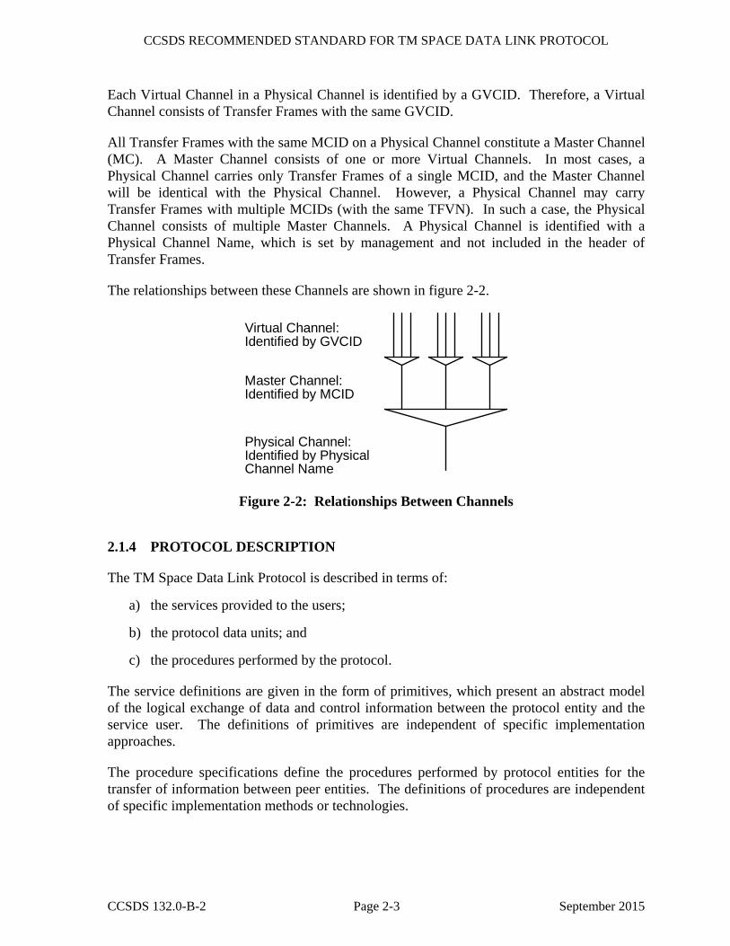
Each Virtual Channel in a Physical Channel is identified by a GVCID. Therefore, a Virtual Channel consists of Transfer Frames with the same GVCID.
All Transfer Frames with the same MCID on a Physical Channel constitute a Master Channel (MC). A Master Channel consists of one or more Virtual Channels. In most cases, a Physical Channel carries only Transfer Frames of a single MCID, and the Master Channel will be identical with the Physical Channel. However, a Physical Channel may carry Transfer Frames with multiple MCIDs (with the same TFVN). In such a case, the Physical Channel consists of multiple Master Channels. A Physical Channel is identified with a Physical Channel Name, which is set by management and not included in the header of Transfer Frames.
The relationships between these Channels are shown in figure 2-2.
Physical Channel:Identified by PhysicalChannel Name
Virtual Channel:Identified by GVCID
Master Channel:Identified by MCID
Figure 2-2: Relationships Between Channels
2.1.4 PROTOCOL DESCRIPTION
The TM Space Data Link Protocol is described in terms of:
a) the services provided to the users;
b) the protocol data units; and
c) the procedures performed by the protocol.
The service definitions are given in the form of primitives, which present an abstract model of the logical exchange of data and control information between the protocol entity and the service user. The definitions of primitives are independent of specific implementation approaches.
The procedure specifications define the procedures performed by protocol entities for the transfer of information between peer entities. The definitions of procedures are independent of specific implementation methods or technologies.

CCSDS RECOMMENDED STANDARD FOR TM SPACE DATA LINK PROTOCOL
CCSDS 132.0-B-2 Page 2-4 September 2015
This protocol specification also specifies the requirements for the underlying services provided by the Channel Coding Sublayer and the Physical Layer.
2.2 OVERVIEW OF SERVICES
2.2.1 COMMON FEATURES OF SERVICES
The TM Space Data Link Protocol provides users with data transfer services. The point at which a service is provided by a protocol entity to a user is called a Service Access Point (SAP) (see reference [1]). Each service user is identified by a SAP address.
Service data units submitted to a SAP are processed in the order of submission. No processing order is maintained for service data units submitted to different SAPs.
NOTE – Implementations may be required to perform flow control at a SAP between the service user and the service provider. However, CCSDS does not make any recommendations for a scheme for flow control between the user and the provider.
The followings are features common to all the services defined by this Recommended Standard:
a) unidirectional (one way) services: one end of a connection can send, but not receive, data through the space link, while the other end can receive, but not send;
b) unconfirmed services: the sending user does not receive confirmation from the receiving end that data has been received;
c) incomplete services: the services do not guarantee completeness, but some services may signal gaps in the sequence of service data units delivered to the receiving user;
d) sequence-preserving services: the sequence of service data units supplied by the sending user is preserved through the transfer over the space link, although there may be gaps and duplications in the sequence of service data units delivered to the receiving user.
NOTE – This Recommended Standard assumes that these services are provided at the end points of a space link. However, this Recommended Standard makes no assumptions concerning how these end points are composed or configured either on-board a spacecraft or in a ground system. In a ground system, the services defined by this Recommended Standard may be extended or enhanced with Space Link Extension Services (reference [B5]).
CCSDS RECOMMENDED STANDARD FOR TM SPACE DATA LINK PROTOCOL
CCSDS 132.0-B-2 Page 2-5 September 2015
2.2.2 SERVICE TYPES
2.2.2.1 Overview
The TM Space Data Link Protocol provides three service types (asynchronous, synchronous, and periodic) that determine how service data units supplied by the user are transferred in protocol data units over a space link.
The models shown below are intended only to illustrate the characteristics of services. They are not intended to guide or restrict design of on-board or ground systems.
2.2.2.2 Asynchronous Service
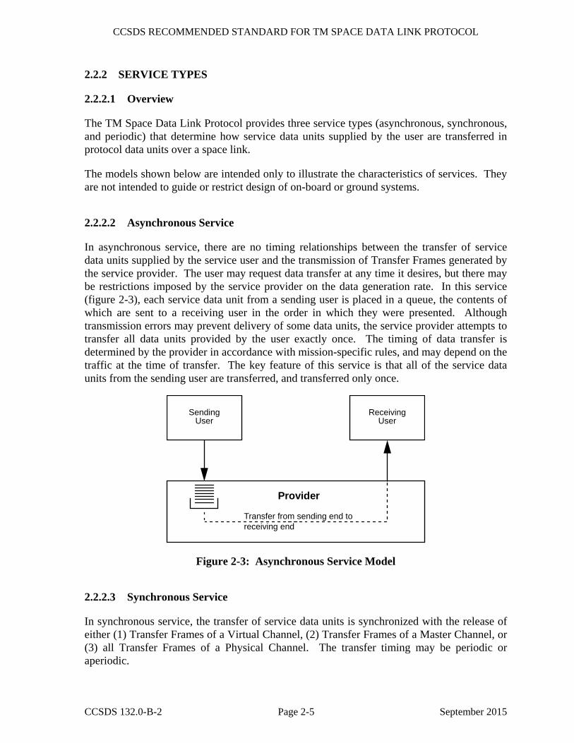
In asynchronous service, there are no timing relationships between the transfer of service data units supplied by the service user and the transmission of Transfer Frames generated by the service provider. The user may request data transfer at any time it desires, but there may be restrictions imposed by the service provider on the data generation rate. In this service (figure 2-3), each service data unit from a sending user is placed in a queue, the contents of which are sent to a receiving user in the order in which they were presented. Although transmission errors may prevent delivery of some data units, the service provider attempts to transfer all data units provided by the user exactly once. The timing of data transfer is determined by the provider in accordance with mission-specific rules, and may depend on the traffic at the time of transfer. The key feature of this service is that all of the service data units from the sending user are transferred, and transferred only once.
SendingUser
ReceivingUser
Provider
Transfer from sending end toreceiving end
Figure 2-3: Asynchronous Service Model
2.2.2.3 Synchronous Service
In synchronous service, the transfer of service data units is synchronized with the release of either (1) Transfer Frames of a Virtual Channel, (2) Transfer Frames of a Master Channel, or (3) all Transfer Frames of a Physical Channel. The transfer timing may be periodic or aperiodic.
CCSDS RECOMMENDED STANDARD FOR TM SPACE DATA LINK PROTOCOL
CCSDS 132.0-B-2 Page 2-6 September 2015
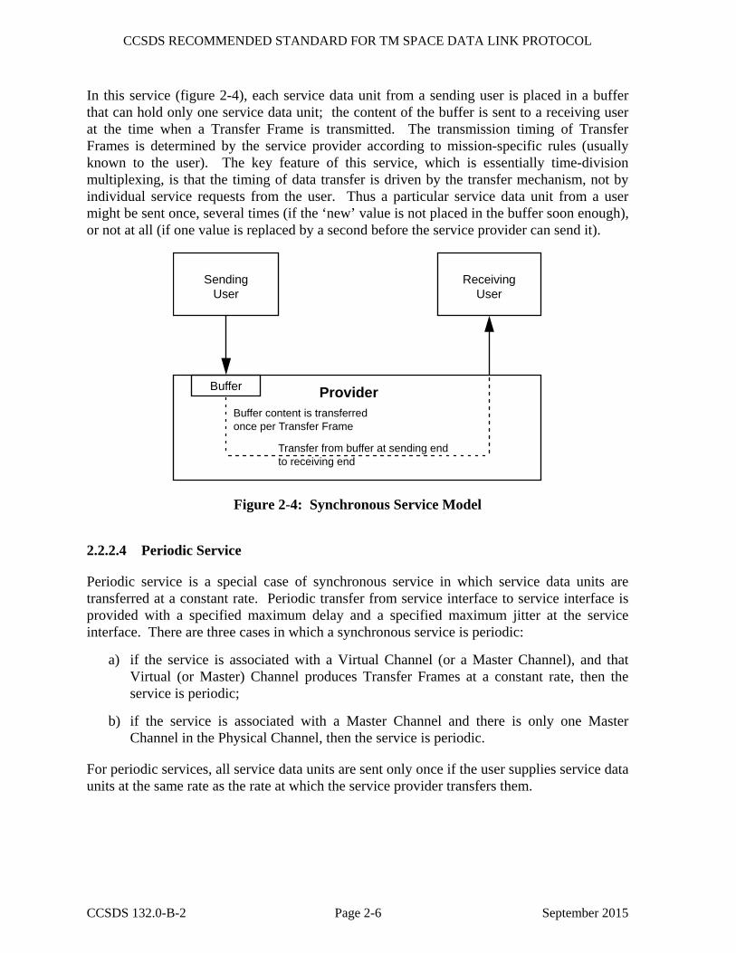
In this service (figure 2-4), each service data unit from a sending user is placed in a buffer that can hold only one service data unit; the content of the buffer is sent to a receiving user at the time when a Transfer Frame is transmitted. The transmission timing of Transfer Frames is determined by the service provider according to mission-specific rules (usually known to the user). The key feature of this service, which is essentially time-division multiplexing, is that the timing of data transfer is driven by the transfer mechanism, not by individual service requests from the user. Thus a particular service data unit from a user might be sent once, several times (if the ‘new’ value is not placed in the buffer soon enough), or not at all (if one value is replaced by a second before the service provider can send it).
Provider
ReceivingUser
Transfer from buffer at sending endto receiving end
SendingUser
Buffer
Buffer content is transferredonce per Transfer Frame
Figure 2-4: Synchronous Service Model
2.2.2.4 Periodic Service
Periodic service is a special case of synchronous service in which service data units are transferred at a constant rate. Periodic transfer from service interface to service interface is provided with a specified maximum delay and a specified maximum jitter at the service interface. There are three cases in which a synchronous service is periodic:
a) if the service is associated with a Virtual Channel (or a Master Channel), and that Virtual (or Master) Channel produces Transfer Frames at a constant rate, then the service is periodic;
b) if the service is associated with a Master Channel and there is only one Master Channel in the Physical Channel, then the service is periodic.
For periodic services, all service data units are sent only once if the user supplies service data units at the same rate as the rate at which the service provider transfers them.

CCSDS RECOMMENDED STANDARD FOR TM SPACE DATA LINK PROTOCOL
CCSDS 132.0-B-2 Page 2-7 September 2015
2.2.3 SUMMARY OF SERVICES
2.2.3.1 General
Eight services are provided by the TM Space Data Link Protocol. Five of them (Virtual Channel Packet, Virtual Channel Access, Virtual Channel Frame Secondary Header, Virtual Channel Operational Control Field, and Virtual Channel Frame) are provided for a Virtual Channel. Three of them (Master Channel Frame Secondary Header, Master Channel Operational Control Field, and Master Channel Frame) are provided for a Master Channel.
Table 2-1 summarizes these services and shows their characteristics and the Service Data Units (SDUs) that they transfer.
Table 2-1: Summary of Services Provided by TM Space Data Link Protocol
Service Service Type Service Data Unit
SAP Address
Virtual Channel Packet (VCP) Asynchronous Packet GVCID + Packet Version Number
Virtual Channel Access (VCA) Asynchronous or Periodic
VCA_SDU GVCID
Virtual Channel Frame Secondary Header (VC_FSH)
Synchronous or Periodic
FSH_SDU GVCID
Virtual Channel Operational Control Field (VC_OCF)
Synchronous or Periodic
OCF_SDU GVCID
Virtual Channel Frame (VCF) Asynchronous or Periodic
Transfer Frame GVCID
Master Channel Frame Secondary Header (MC_FSH)
Synchronous or Periodic
FSH_SDU MCID
Master Channel Operational Control Field (MC_OCF)
Synchronous or Periodic
OCF_SDU MCID
Master Channel Frame (MCF) Asynchronous or Periodic
Transfer Frame MCID
† In this document, the term ‘Packet Service’ is used as an abbreviation for Virtual Channel Packet (VCP) Service.
CCSDS RECOMMENDED STANDARD FOR TM SPACE DATA LINK PROTOCOL
CCSDS 132.0-B-2 Page 2-8 September 2015
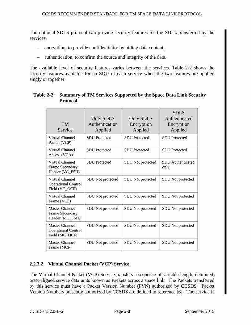
The optional SDLS protocol can provide security features for the SDUs transferred by the services:
– encryption, to provide confidentiality by hiding data content;
– authentication, to confirm the source and integrity of the data.
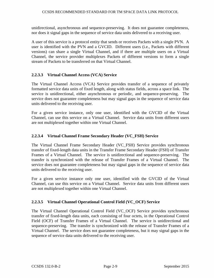
The available level of security features varies between the services. Table 2-2 shows the security features available for an SDU of each service when the two features are applied singly or together.
Table 2-2: Summary of TM Services Supported by the Space Data Link Security Protocol
TM Service
Only SDLS Authentication
Applied
Only SDLS Encryption
Applied
SDLS Authenticated
Encryption Applied
Virtual Channel Packet (VCP)
SDU Protected SDU Protected SDU Protected
Virtual Channel Access (VCA)
SDU Protected SDU Protected SDU Protected
Virtual Channel Frame Secondary Header (VC_FSH)
SDU Protected SDU Not protected SDU Authenticated only
Virtual Channel Operational Control Field (VC_OCF)
SDU Not protected SDU Not protected SDU Not protected
Virtual Channel Frame (VCF)
SDU Not protected SDU Not protected SDU Not protected
Master Channel Frame Secondary Header (MC_FSH)
SDU Not protected SDU Not protected SDU Not protected
Master Channel Operational Control Field (MC_OCF)
SDU Not protected SDU Not protected SDU Not protected
Master Channel Frame (MCF)
SDU Not protected SDU Not protected SDU Not protected
2.2.3.2 Virtual Channel Packet (VCP) Service
The Virtual Channel Packet (VCP) Service transfers a sequence of variable-length, delimited, octet-aligned service data units known as Packets across a space link. The Packets transferred by this service must have a Packet Version Number (PVN) authorized by CCSDS. Packet Version Numbers presently authorized by CCSDS are defined in reference [6]. The service is
CCSDS RECOMMENDED STANDARD FOR TM SPACE DATA LINK PROTOCOL
CCSDS 132.0-B-2 Page 2-9 September 2015
unidirectional, asynchronous and sequence-preserving. It does not guarantee completeness, nor does it signal gaps in the sequence of service data units delivered to a receiving user.
A user of this service is a protocol entity that sends or receives Packets with a single PVN. A user is identified with the PVN and a GVCID. Different users (i.e., Packets with different versions) can share a single Virtual Channel, and if there are multiple users on a Virtual Channel, the service provider multiplexes Packets of different versions to form a single stream of Packets to be transferred on that Virtual Channel.
2.2.3.3 Virtual Channel Access (VCA) Service
The Virtual Channel Access (VCA) Service provides transfer of a sequence of privately formatted service data units of fixed length, along with status fields, across a space link. The service is unidirectional, either asynchronous or periodic, and sequence-preserving. The service does not guarantee completeness but may signal gaps in the sequence of service data units delivered to the receiving user.
For a given service instance, only one user, identified with the GVCID of the Virtual Channel, can use this service on a Virtual Channel. Service data units from different users are not multiplexed together within one Virtual Channel.
2.2.3.4 Virtual Channel Frame Secondary Header (VC_FSH) Service
The Virtual Channel Frame Secondary Header (VC_FSH) Service provides synchronous transfer of fixed-length data units in the Transfer Frame Secondary Header (FSH) of Transfer Frames of a Virtual Channel. The service is unidirectional and sequence-preserving. The transfer is synchronized with the release of Transfer Frames of a Virtual Channel. The service does not guarantee completeness but may signal gaps in the sequence of service data units delivered to the receiving user.
For a given service instance only one user, identified with the GVCID of the Virtual Channel, can use this service on a Virtual Channel. Service data units from different users are not multiplexed together within one Virtual Channel.
2.2.3.5 Virtual Channel Operational Control Field (VC_OCF) Service
The Virtual Channel Operational Control Field (VC_OCF) Service provides synchronous transfer of fixed-length data units, each consisting of four octets, in the Operational Control Field (OCF) of Transfer Frames of a Virtual Channel. The service is unidirectional and sequence-preserving. The transfer is synchronized with the release of Transfer Frames of a Virtual Channel. The service does not guarantee completeness, but it may signal gaps in the sequence of service data units delivered to the receiving user.
CCSDS RECOMMENDED STANDARD FOR TM SPACE DATA LINK PROTOCOL
CCSDS 132.0-B-2 Page 2-10 September 2015
For a given service instance only one user, identified with the GVCID of the Virtual Channel, can use this service on a Virtual Channel. Service data units from different users are not multiplexed together within one Virtual Channel.
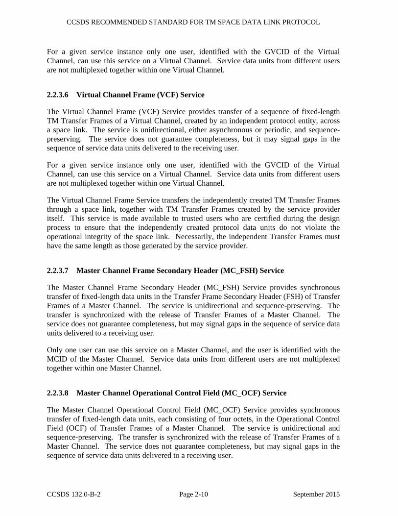
2.2.3.6 Virtual Channel Frame (VCF) Service
The Virtual Channel Frame (VCF) Service provides transfer of a sequence of fixed-length TM Transfer Frames of a Virtual Channel, created by an independent protocol entity, across a space link. The service is unidirectional, either asynchronous or periodic, and sequence-preserving. The service does not guarantee completeness, but it may signal gaps in the sequence of service data units delivered to the receiving user.
For a given service instance only one user, identified with the GVCID of the Virtual Channel, can use this service on a Virtual Channel. Service data units from different users are not multiplexed together within one Virtual Channel.
The Virtual Channel Frame Service transfers the independently created TM Transfer Frames through a space link, together with TM Transfer Frames created by the service provider itself. This service is made available to trusted users who are certified during the design process to ensure that the independently created protocol data units do not violate the operational integrity of the space link. Necessarily, the independent Transfer Frames must have the same length as those generated by the service provider.
2.2.3.7 Master Channel Frame Secondary Header (MC_FSH) Service
The Master Channel Frame Secondary Header (MC_FSH) Service provides synchronous transfer of fixed-length data units in the Transfer Frame Secondary Header (FSH) of Transfer Frames of a Master Channel. The service is unidirectional and sequence-preserving. The transfer is synchronized with the release of Transfer Frames of a Master Channel. The service does not guarantee completeness, but may signal gaps in the sequence of service data units delivered to a receiving user.
Only one user can use this service on a Master Channel, and the user is identified with the MCID of the Master Channel. Service data units from different users are not multiplexed together within one Master Channel.
2.2.3.8 Master Channel Operational Control Field (MC_OCF) Service
The Master Channel Operational Control Field (MC_OCF) Service provides synchronous transfer of fixed-length data units, each consisting of four octets, in the Operational Control Field (OCF) of Transfer Frames of a Master Channel. The service is unidirectional and sequence-preserving. The transfer is synchronized with the release of Transfer Frames of a Master Channel. The service does not guarantee completeness, but may signal gaps in the sequence of service data units delivered to a receiving user.
CCSDS RECOMMENDED STANDARD FOR TM SPACE DATA LINK PROTOCOL
CCSDS 132.0-B-2 Page 2-11 September 2015
Only one user can use this service on a Master Channel, and the user is identified with the MCID of the Master Channel. Service data units from different users are not multiplexed together within one Master Channel.
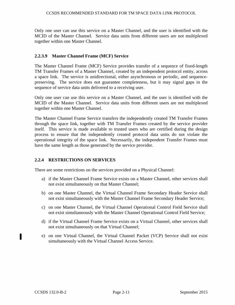
2.2.3.9 Master Channel Frame (MCF) Service
The Master Channel Frame (MCF) Service provides transfer of a sequence of fixed-length TM Transfer Frames of a Master Channel, created by an independent protocol entity, across a space link. The service is unidirectional, either asynchronous or periodic, and sequence-preserving. The service does not guarantee completeness, but it may signal gaps in the sequence of service data units delivered to a receiving user.
Only one user can use this service on a Master Channel, and the user is identified with the MCID of the Master Channel. Service data units from different users are not multiplexed together within one Master Channel.
The Master Channel Frame Service transfers the independently created TM Transfer Frames through the space link, together with TM Transfer Frames created by the service provider itself. This service is made available to trusted users who are certified during the design process to ensure that the independently created protocol data units do not violate the operational integrity of the space link. Necessarily, the independent Transfer Frames must have the same length as those generated by the service provider.
2.2.4 RESTRICTIONS ON SERVICES
There are some restrictions on the services provided on a Physical Channel:
a) if the Master Channel Frame Service exists on a Master Channel, other services shall not exist simultaneously on that Master Channel;
b) on one Master Channel, the Virtual Channel Frame Secondary Header Service shall not exist simultaneously with the Master Channel Frame Secondary Header Service;
c) on one Master Channel, the Virtual Channel Operational Control Field Service shall not exist simultaneously with the Master Channel Operational Control Field Service;
d) if the Virtual Channel Frame Service exists on a Virtual Channel, other services shall not exist simultaneously on that Virtual Channel;
e) on one Virtual Channel, the Virtual Channel Packet (VCP) Service shall not exist simultaneously with the Virtual Channel Access Service.

CCSDS RECOMMENDED STANDARD FOR TM SPACE DATA LINK PROTOCOL
CCSDS 132.0-B-2 Page 2-12 September 2015
2.3 OVERVIEW OF FUNCTIONS
2.3.1 GENERAL FUNCTIONS
The TM Space Data Link Protocol transfers various service data units supplied by sending users encapsulated in a sequence of protocol data units using services of lower layers. The protocol data units, known as TM Transfer Frames, have a fixed length and must be transferred over a Physical Channel at a constant rate.
The protocol entity performs the following protocol functions:
a) generation and processing of protocol control information (i.e., headers and trailers) to perform data identification, loss detection, and error detection;
b) segmenting and blocking of service data units to transfer variable-length service data units in fixed-length protocol data units;
c) multiplexing/demultiplexing and commutation/decommutation in order for various service users to share a single Physical Channel;
d) generation and removal of idle data to transfer protocol data units at a constant rate.
If the protocol entity supports the optional SDLS protocol, then it uses the functions of SDLS to apply the configured security features.
The protocol entity does not perform the following protocol functions:
a) connection establishment and release;
b) flow control;
c) retransmission of protocol data units;
d) management or configuration of the SDLS protocol.
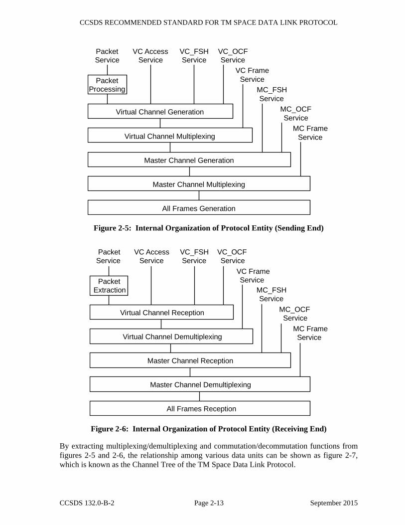
2.3.2 INTERNAL ORGANIZATION OF PROTOCOL ENTITY
Figures 2-5 and 2-6 show the internal organization of the protocol entity of the sending and receiving ends, respectively. Data flow from top to bottom in figure 2-5, and from bottom to top in figure 2-6. These figures identify data-handling functions performed by the protocol entity and show logical relationships among these functions. The figures are not intended to imply any hardware or software configuration in a real system. Depending on the services actually used for a real system, not all of the functions may be present in the protocol entity.
CCSDS RECOMMENDED STANDARD FOR TM SPACE DATA LINK PROTOCOL
CCSDS 132.0-B-2 Page 2-13 September 2015
MC FrameService
VC FrameService
MC_OCFService
MC_FSHService
PacketService
VC AccessService
Virtual Channel Multiplexing
Virtual Channel Generation
PacketProcessing
Master Channel Generation
Master Channel Multiplexing
All Frames Generation
VC_FSHService
VC_OCFService
Figure 2-5: Internal Organization of Protocol Entity (Sending End)
MC FrameService
VC FrameService
MC_OCFService
MC_FSHService
PacketService
VC AccessService
Virtual Channel Demultiplexing
Virtual Channel Reception
PacketExtraction
Master Channel Reception
Master Channel Demultiplexing
All Frames Reception
VC_FSHService
VC_OCFService
Figure 2-6: Internal Organization of Protocol Entity (Receiving End)
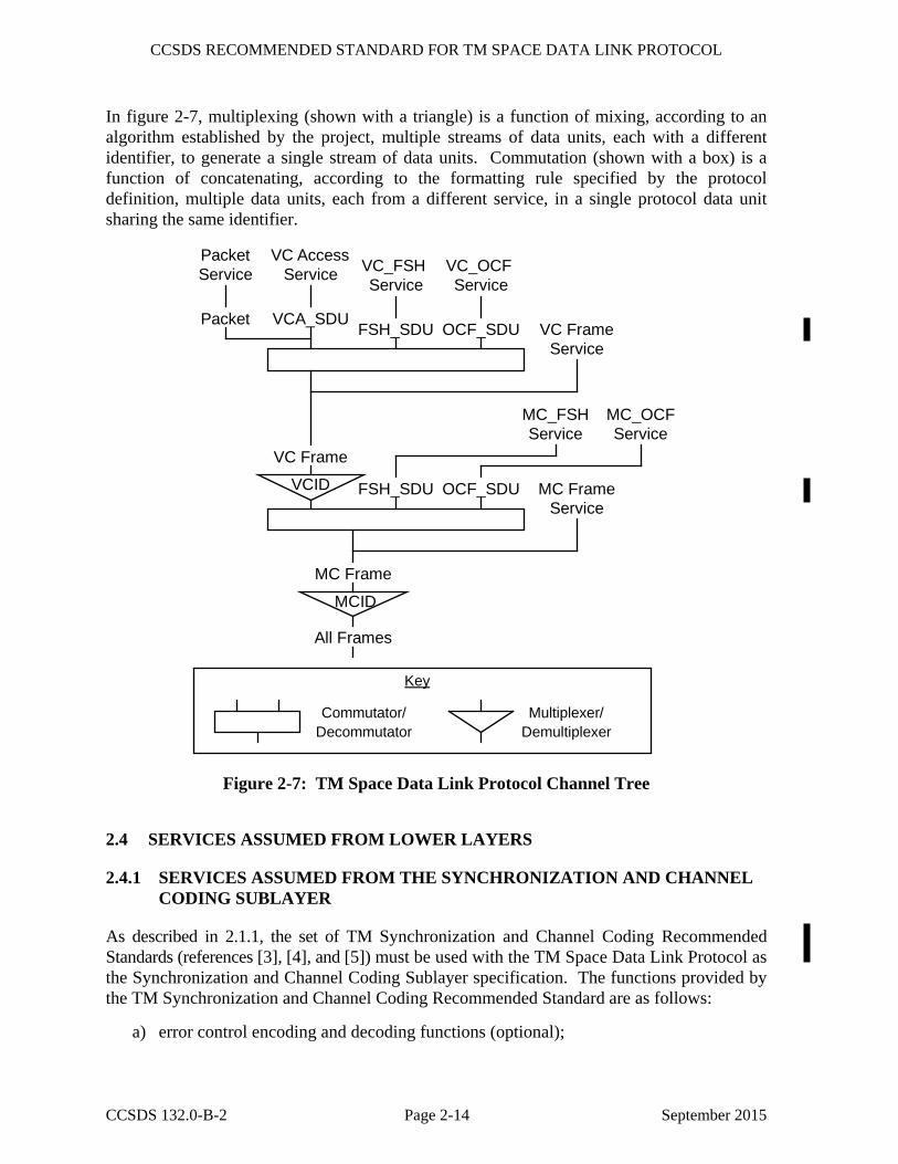
By extracting multiplexing/demultiplexing and commutation/decommutation functions from figures 2-5 and 2-6, the relationship among various data units can be shown as figure 2-7, which is known as the Channel Tree of the TM Space Data Link Protocol.
CCSDS RECOMMENDED STANDARD FOR TM SPACE DATA LINK PROTOCOL
CCSDS 132.0-B-2 Page 2-14 September 2015
In figure 2-7, multiplexing (shown with a triangle) is a function of mixing, according to an algorithm established by the project, multiple streams of data units, each with a different identifier, to generate a single stream of data units. Commutation (shown with a box) is a function of concatenating, according to the formatting rule specified by the protocol definition, multiple data units, each from a different service, in a single protocol data unit sharing the same identifier.
MC FrameService
VC FrameService
MC_OCFService
PacketService
VC AccessService
OCF_SDU
FSH_SDUVCA_SDUPacket
VC_FSHService
MCID
VCID
All Frames
VC Frame
MC Frame
Commutator/Decommutator
Key
Multiplexer/Demultiplexer
OCF_SDU
VC_OCFService
FSH_SDU
MC_FSHService
Figure 2-7: TM Space Data Link Protocol Channel Tree
2.4 SERVICES ASSUMED FROM LOWER LAYERS
2.4.1 SERVICES ASSUMED FROM THE SYNCHRONIZATION AND CHANNEL CODING SUBLAYER
As described in 2.1.1, the set of TM Synchronization and Channel Coding Recommended Standards (references [3], [4], and [5]) must be used with the TM Space Data Link Protocol as the Synchronization and Channel Coding Sublayer specification. The functions provided by the TM Synchronization and Channel Coding Recommended Standard are as follows:
a) error control encoding and decoding functions (optional);

CCSDS RECOMMENDED STANDARD FOR TM SPACE DATA LINK PROTOCOL
CCSDS 132.0-B-2 Page 2-15 September 2015
b) bit transition generation and removal functions (optional);
c) delimiting and synchronizing functions.
The Synchronization and Channel Coding Sublayer, then, transfers contiguous, fixed-length, delimited protocol data units as a contiguous stream of bits over a space link using the services of the underlying Physical Layer.
2.4.2 PERFORMANCE REQUIREMENTS TO LOWER LAYERS
The coding options of the TM Channel Coding and Synchronization Recommended Standard and the performance of the RF link provided by the Physical Layer shall be chosen according to the following criteria:
a) the probability of misidentifying the MCID and VCID shall be less than a mission-specified value;
b) the probability of not correctly extracting Packets from Transfer Frames using the First Header Pointer and the Packet Length Field shall be less than a mission-specified value.
In order to assure correct decoding at the receiving end, the same coding options must be applied to all Transfer Frames of a Physical Channel.
CCSDS RECOMMENDED STANDARD FOR TM SPACE DATA LINK PROTOCOL
CCSDS 132.0-B-2 Page 3-1 September 2015
3 SERVICE DEFINITION
3.1 OVERVIEW
This section provides service definition in the form of primitives, which present an abstract model of the logical exchange of data and control information between the protocol entity and the service user. The definitions of primitives are independent of specific implementation approaches.
The parameters of the primitives are specified in an abstract sense and specify the information to be made available to the user of the primitives. The way in which a specific implementation makes this information available is not constrained by this specification. In addition to the parameters specified in this section, an implementation may provide other parameters to the service user (e.g., parameters for controlling the service, monitoring performance, facilitating diagnosis, and so on).
3.2 SOURCE DATA
3.2.1 SOURCE DATA OVERVIEW
NOTE – This subsection describes the service data units that are transferred from sending users to receiving users by the TM Space Data Link Protocol.
The service data units transferred by the TM Space Data Link Protocol are as follows:
a) Packet;
b) Virtual Channel Access Service Data Unit (VCA_SDU);
c) Frame Secondary Header Service Data Unit (FSH_SDU);
d) Operational Control Field Service Data Unit (OCF_SDU);
e) TM Transfer Frame.
3.2.2 PACKET
3.2.2.1 Packets shall be transferred over a space link via the Virtual Channel Packet (VCP) Service.
3.2.2.2 The Packets transferred by this service must have a Packet Version Number (PVN) authorized by CCSDS. Further, each Packet transferred must conform to the corresponding packet format specified by reference [6].
3.2.2.3 The position and length of the Packet Length Field of the Packets must be known to the service provider in order to extract Packets from Transfer Frames at the receiving end.

CCSDS RECOMMENDED STANDARD FOR TM SPACE DATA LINK PROTOCOL
CCSDS 132.0-B-2 Page 3-2 September 2015
NOTES
1 Packets are variable-length, delimited, octet-aligned data units, and are usually the protocol data unit of a Network Layer protocol.
2 PVNs presently authorized by CCSDS are defined in reference [6].
3.2.3 VIRTUAL CHANNEL ACCESS SERVICE DATA UNIT (VCA_SDU)
VCA_SDUs shall be transferred over a space link with the Virtual Channel Access Service.
NOTE – Virtual Channel Access Service Data Units (VCA_SDUs) are fixed-length, octet-aligned data units, the format of which is unknown to the service provider. Their length is established by management.
3.2.4 FRAME SECONDARY HEADER SERVICE DATA UNIT (FSH_SDU)
3.2.4.1 Frame Secondary Header Service Data Units (FSH_SDUs) shall be transferred over a space link with the VC_FSH or MC_FSH Service. Data units may be carried in every frame of a Virtual Channel, using the VC_FSH Service, or, in every frame of a Master Channel, using the MC_FSH Service.
3.2.4.2 Although the transfer of FSH_SDUs is synchronized with the Virtual Channel or Master Channel that will provide the transfer service, the creation of FSH_SDUs by the sending user may or may not be synchronized with the Virtual Channel or Master Channel. Such synchronization, if required for timing or other purposes, is a mission-design issue.
NOTE – Frame Secondary Header Service Data Units (FSH_SDUs) are fixed-length data units carried in the Transfer Frame Secondary Header (FSH), defined in 4.1.3, from a sending end to a receiving end. Their length may be of any constant value which is an integral number of octets, between 2 octets and 64 octets. It is static within the associated Master or Virtual Channel, and is established by management. Except for the Frame Secondary Header Identification Field defined in 4.1.3.2, CCSDS specifies no format or semantics for the content of an FSH_SDU.
3.2.5 OPERATIONAL CONTROL FIELD SERVICE DATA UNIT (OCF_SDU)
3.2.5.1 Operational Control Field Service Data Units (OCF_SDUs) shall be transferred over a space link with the VC_OCF or MC_OCF Service. Data units may be carried in every frame of a Virtual Channel, using the VC_OCF Service, or, in every frame of a Master Channel, using the MC_OCF Service.
3.2.5.2 Although the transfer of OCF_SDUs is synchronized with the Virtual Channel or Master Channel that shall provide the transfer service, the creation of OCF_SDUs by the
CCSDS RECOMMENDED STANDARD FOR TM SPACE DATA LINK PROTOCOL
CCSDS 132.0-B-2 Page 3-3 September 2015
sending user may or may not be synchronized with the Virtual Channel or Master Channel. Such synchronization, if required for timing or other purposes, is a mission-design issue.
NOTE – Operational Control Field Service Data Units (OCF_SDUs) are fixed-length data units, each consisting of four octets, carried in the Operational Control Field (OCF), defined in 4.1.5, from a sending end to a receiving end. As defined in 4.1.5, CCSDS specifies the use of the first bit of this field to indicate the type of data carried.
3.2.6 TM TRANSFER FRAME
Transfer Frames transferred by the Virtual Channel Frame and Master Channel Frame Services shall be partially formatted TM Transfer Frames, and the following restrictions apply:
a) the Master Channel Frame Count Field of the Transfer Frames submitted to the Virtual Channel Frame Service shall be empty;
b) if the MC_FSH Service exists on a Master Channel, the Transfer Frame Secondary Header and the Transfer Frame Secondary Header Flag of the Transfer Frames submitted to the Virtual Channel Frame Service on the same Master Channel shall be empty;
c) if the MC_OCF Service exists on a Master Channel, the Operational Control Field and the Operational Control Field Flag of the Transfer Frames submitted to the Virtual Channel Frame Service on the same Master Channel shall be empty;
d) the Frame Error Control Field of the Transfer Frames submitted to the Master or Virtual Channel Frame Service shall be empty, if it is present on the Physical Channel.
NOTE – The TM Transfer Frame is the fixed-length protocol data unit of the TM Space Data Link Protocol, but also can be used as the service data units of the Virtual Channel Frame and Master Channel Frame Services. Its format is defined in 4.1 and 6.3 of this Recommended Standard. The length of any Transfer Frame transferred on a Physical Channel must be the same, and is established by management.
CCSDS RECOMMENDED STANDARD FOR TM SPACE DATA LINK PROTOCOL
CCSDS 132.0-B-2 Page 3-4 September 2015
3.3 VIRTUAL CHANNEL PACKET (VCP) SERVICE
3.3.1 OVERVIEW OF VCP SERVICE
The Virtual Channel Packet (VCP) Service transfers a sequence of variable-length, delimited, octet-aligned service data units known as Packets across a space link. The Packets transferred by this service must have a Packet Version Number (PVN) authorized by CCSDS. Packet Version Numbers presently authorized by CCSDS are defined in reference [6]. The service is unidirectional, asynchronous and sequence-preserving. It does not guarantee completeness, nor does it signal gaps in the sequence of service data units delivered to a receiving user.
A user of this service is a protocol entity that sends or receives Packets with a single PVN. A user is identified with the PVN and a GVCID. Different users (i.e., Packets with different versions) can share a single Virtual Channel, and if there are multiple users on a Virtual Channel, the service provider multiplexes Packets of different versions to form a single stream of Packets to be transferred on that Virtual Channel.
3.3.2 VCP SERVICE PARAMETERS
3.3.2.1 General
The parameters used by the VCP Service primitives shall conform to the specifications contained in 3.3.2.2 through 3.3.2.6.
3.3.2.2 Packet
The Packet parameter shall contain a Packet for transfer by the VCP Service.
NOTE – The Packet parameter is the service data unit transferred by the VCP Service. Restrictions on the Packets transferred by the VCP Service are stated in 3.2.2.
3.3.2.3 GVCID
The GVCID parameter shall contain a GVCID that indicates the Virtual Channel through which the Packet is to be transferred.
NOTE – The GVCID parameter is part of the SAP address of the VCP Service.
3.3.2.4 Packet Version Number
NOTE – The Packet Version Number parameter is part of the SAP address of the VCP Service and identifies the protocol entity of the upper layer that uses the VCP Service.

CCSDS RECOMMENDED STANDARD FOR TM SPACE DATA LINK PROTOCOL
CCSDS 132.0-B-2 Page 3-5 September 2015
3.3.2.5 Packet Quality Indicator
3.3.2.5.1 The Packet Quality Indicator is an optional parameter that may be used to notify the user at the receiving end of the VCP Service whether the Packet delivered by the primitive is complete or partial.
3.3.2.5.2 This parameter shall be used when the service provider is required to deliver incomplete Packets to the user at the receiving end.
3.3.2.6 Verification Status Code
3.3.2.6.1 The Verification Status Code is an optional parameter that may be used if the service provider supports the optional SDLS protocol.
3.3.2.6.2 The parameter shall be used to notify the user at the receiving end of the VCP Service of a verification failure in a transfer frame addressed to the Virtual Channel.
3.3.2.6.3 A non-zero value shall indicate that the SDLS protocol has detected an error; the values taken by this parameter are defined in reference [10].
3.3.2.6.4 Data from the failed transfer frame shall not be delivered to the service user.
3.3.3 VCP SERVICE PRIMITIVES
3.3.3.1 General
The service primitives associated with the VCP Service are:
a) VCP.request;
b) VCP.indication.
CCSDS RECOMMENDED STANDARD FOR TM SPACE DATA LINK PROTOCOL
CCSDS 132.0-B-2 Page 3-6 September 2015
3.3.3.2 VCP.request
3.3.3.2.1 Function
At the sending end, the VCP Service user shall pass a VCP.request primitive to the service provider to request that a Packet be transferred to the user at the receiving end through the specified Virtual Channel.
NOTE – The VCP.request primitive is the service request primitive for the VCP Service.
3.3.3.2.2 Semantics
The VCP.request primitive shall provide parameters as follows:
VCP.request (Packet, GVCID, Packet Version Number)
3.3.3.2.3 When Generated
The VCP.request primitive shall be passed to the service provider to request it to send the Packet.
3.3.3.2.4 Effect On Receipt
Receipt of the VCP.request primitive shall cause the service provider to transfer the Packet.
3.3.3.2.5 Additional Comments
The VCP.request primitive shall be used to transfer Packets across the space link on the specified Virtual Channel.
CCSDS RECOMMENDED STANDARD FOR TM SPACE DATA LINK PROTOCOL
CCSDS 132.0-B-2 Page 3-7 September 2015
3.3.3.3 VCP.indication
3.3.3.3.1 Function
At the receiving end, the service provider shall pass a VCP.indication to the VCP Service user to deliver a Packet.
NOTE – The VCP.indication primitive is the service indication primitive for the VCP Service.
3.3.3.3.2 Semantics
The VCP.indication primitive shall provide parameters as follows:
VCP.indication (Packet, GVCID, Packet Version Number, Packet Quality Indicator (optional), Verification Status Code (optional))
3.3.3.3.3 When Generated
The VCP.indication primitive shall be passed from the service provider to the VCP Service user at the receiving end to deliver a Packet.
3.3.3.3.4 Effect On Receipt
The effect of receipt of the VCP.indication primitive by the VCP Service user is undefined.
3.3.3.3.5 Additional Comments
The VCP.indication primitive shall be used to deliver Packets to the VCP Service user identified by the GVCID and Packet Version Number. Incomplete Packets may be delivered (optional).
CCSDS RECOMMENDED STANDARD FOR TM SPACE DATA LINK PROTOCOL
CCSDS 132.0-B-2 Page 3-8 September 2015
3.4 VIRTUAL CHANNEL ACCESS (VCA) SERVICE
3.4.1 OVERVIEW OF VCA SERVICE
The Virtual Channel Access (VCA) Service provides transfer of a sequence of privately formatted service data units of fixed length, along with status fields, across a space link. The service is unidirectional, either asynchronous or periodic, and sequence-preserving. The service does not guarantee completeness, but it may signal gaps in the sequence of service data units delivered to the receiving user.
Only one user, identified with the GVCID of the Virtual Channel, can use this service on a Virtual Channel. Service data units from different users are not multiplexed together within one Virtual Channel.
3.4.2 VCA SERVICE PARAMETERS
3.4.2.1 General
The parameters used by the VCA Service primitives shall conform to the specifications contained in 3.4.2.2 through 3.4.2.6.
3.4.2.2 VCA_SDU
NOTE – The VCA_SDU parameter is the service data unit transferred by the VCA Service. Restrictions on the VCA_SDUs transferred by the VCA Service are stated in 3.2.3.
3.4.2.3 VCA Status Fields
The Packet Order Flag (1 bit) and Segment Length ID (2 bits) may be used to convey information on the validity, sequence, or other status of the VCA_SDUs. Provision of this field is mandatory; semantics are user-optional.
NOTE – The VCA Status Fields parameter consists of the Transfer Frame First Header Pointer Field and three other bits of the Transfer Frame Status Field: the Packet Order Flag (1 bit), and Segment Length ID (2 bits). These are undefined by CCSDS when a Virtual Channel is used to transfer VCA_SDUs.
3.4.2.4 GVCID
The GVCID parameter shall contain a GVCID that indicates the Virtual Channel through which the VCA_SDU is to be transferred.
NOTE – The GVCID parameter is the SAP address of the VCA Service.
CCSDS RECOMMENDED STANDARD FOR TM SPACE DATA LINK PROTOCOL
CCSDS 132.0-B-2 Page 3-9 September 2015
3.4.2.5 VCA_SDU Loss Flag
The VCA_SDU Loss Flag is an optional parameter that may be used to notify the user at the receiving end of the VCA Service that a sequence discontinuity has been detected and that one or more VCA_SDUs have been lost. If implemented, the flag shall be derived by examining the Virtual Channel Frame Count in the Transfer Frames.
3.4.2.6 Verification Status Code
3.4.2.6.1 The Verification Status Code is an optional parameter that may be used if the service provider supports the optional SDLS protocol.
3.4.2.6.2 The parameter shall be used to notify the user at the receiving end of the VCA Service of a verification failure in a transfer frame addressed to the Virtual Channel.
3.4.2.6.3 A non-zero value shall indicate that the SDLS protocol has detected an error; the values taken by this parameter are defined in reference [10].
3.4.2.6.4 Data from the failed transfer frame shall not be delivered to the service user.
3.4.3 VCA SERVICE PRIMITIVES
3.4.3.1 General
The service primitives associated with the VCA Service are:
a) VCA.request;
b) VCA.indication.
CCSDS RECOMMENDED STANDARD FOR TM SPACE DATA LINK PROTOCOL
CCSDS 132.0-B-2 Page 3-10 September 2015
3.4.3.2 VCA.request
3.4.3.2.1 Function
At the sending end, the VCA Service user shall pass a VCA.request primitive to the service provider to request that a VCA_SDU be transferred to the user at the receiving end through the specified Virtual Channel.
NOTE – The VCA.request primitive is the service request primitive for the VCA Service.
3.4.3.2.2 Semantics
The VCA.request primitive shall provide parameters as follows:
VCA.request (VCA_SDU, VCA Status Fields, GVCID)
3.4.3.2.3 When Generated
The VCA.request primitive shall be passed to the service provider to request it to send the VCA_SDU.
3.4.3.2.4 Effect On Receipt
Receipt of the VCA.request primitive shall cause the service provider to transfer the VCA_SDU.
3.4.3.2.5 Additional Comments
The VCA.request primitive shall be used to transfer VCA_SDUs across the space link on the specified Virtual Channel.
CCSDS RECOMMENDED STANDARD FOR TM SPACE DATA LINK PROTOCOL
CCSDS 132.0-B-2 Page 3-11 September 2015
3.4.3.3 VCA.indication
3.4.3.3.1 Function
At the receiving end, the service provider shall pass a VCA.indication to the VCA Service user to deliver a VCA_SDU.
NOTE – The VCA.indication primitive is the service indication primitive for the VCA Service.
3.4.3.3.2 Semantics
The VCA.indication primitive shall provide parameters as follows:
VCA.indication (VCA_SDU, VCA Status Fields, GVCID, VCA_SDU Loss Flag (optional), Verification Status Code (optional))
3.4.3.3.3 When Generated
The VCA.indication primitive shall be passed from the service provider to the VCA Service user at the receiving end to deliver a VCA_SDU.
3.4.3.3.4 Effect On Receipt
The effect of receipt of the VCA.indication primitive by the VCA Service user is undefined.
3.4.3.3.5 Additional Comments
The VCA.indication primitive shall be used to deliver VCA_SDUs to the VCA Service user identified by the GVCID.

CCSDS RECOMMENDED STANDARD FOR TM SPACE DATA LINK PROTOCOL
CCSDS 132.0-B-2 Page 3-12 September 2015
3.5 VIRTUAL CHANNEL FRAME SECONDARY HEADER (VC_FSH) SERVICE
3.5.1 OVERVIEW OF VC_FSH SERVICE
The Virtual Channel Frame Secondary Header (VC_FSH) Service provides synchronous transfer of fixed-length data units in the Transfer Frame Secondary Header (FSH) of Transfer Frames of a Virtual Channel. The service is unidirectional and sequence-preserving. The transfer is synchronized with the release of Transfer Frames of a Virtual Channel. The service does not guarantee completeness, but it may signal gaps in the sequence of service data units delivered to the receiving user.
Only one user, identified with the GVCID of the Virtual Channel, can use this service on a Virtual Channel. Service data units from different users are not multiplexed together within one Virtual Channel.
3.5.2 VC_FSH SERVICE PARAMETERS
3.5.2.1 General
The parameters used by the VC_FSH Service primitives shall conform to the specifications contained in 3.5.2.2 through 3.5.2.4.
3.5.2.2 FSH_SDU
NOTE – The FSH_SDU parameter is the service data unit transferred by the VC_FSH Service in the Frame Secondary Header of Transfer Frames of a Virtual Channel. Restrictions on the FSH_SDU transferred by the VC_FSH Service are stated in 3.2.4.
3.5.2.3 GVCID
The GVCID parameter shall contain a GVCID that indicates the Virtual Channel through which the FSH_SDU is to be transferred.
NOTE – The GVCID parameter is the SAP address of the VC_FSH Service.
3.5.2.4 FSH_SDU Loss Flag
The FSH_SDU Loss Flag is an optional parameter that may be used to notify the user at the receiving end of the VC_FSH Service that a sequence discontinuity has been detected and that one or more FSH_SDUs may have been lost. If implemented, the flag shall be derived by examining the Virtual Channel Frame Count in the Transfer Frames.
CCSDS RECOMMENDED STANDARD FOR TM SPACE DATA LINK PROTOCOL
CCSDS 132.0-B-2 Page 3-13 September 2015
3.5.3 VC_FSH SERVICE PRIMITIVES
3.5.3.1 General
The service primitives associated with the VC_FSH Service are:
a) VC_FSH.request;
b) VC_FSH.indication.
3.5.3.2 VC_FSH.request
3.5.3.2.1 Function
At the sending end, the VC_FSH Service user shall pass a VC_FSH.request primitive to the service provider to request that an FSH_SDU be transferred to the user at the receiving end through the specified Virtual Channel.
NOTE – The VC_FSH.request primitive is the service request primitive for the VC_FSH Service.
3.5.3.2.2 Semantics
The VC_FSH.request primitive shall provide parameters as follows:
VC_FSH.request (FSH_SDU, GVCID)
3.5.3.2.3 When Generated
The VC_FSH.request primitive shall be passed to the service provider to request it to send the FSH_SDU.
3.5.3.2.4 Effect On Receipt
Receipt of the VC_FSH.request primitive shall cause the service provider to transfer the FSH_SDU.
3.5.3.2.5 Additional Comments
The VC_FSH.request primitive shall be used to transfer FSH_SDUs across the space link on the specified Virtual Channel.
CCSDS RECOMMENDED STANDARD FOR TM SPACE DATA LINK PROTOCOL
CCSDS 132.0-B-2 Page 3-14 September 2015
3.5.3.3 VC_FSH.indication
3.5.3.3.1 Function
At the receiving end, the service provider shall pass a VC_FSH.indication to the VC_FSH Service user to deliver an FSH_SDU.
NOTE – The VC_FSH.indication primitive is the service indication primitive for the VC_FSH Service.
3.5.3.3.2 Semantics
The VC_FSH.indication primitive shall provide parameters as follows:
VC_FSH.indication (FSH_SDU, GVCID, FSH_SDU Loss Flag (optional))
3.5.3.3.3 When Generated
The VC_FSH.indication primitive shall be passed from the service provider to the VC_FSH Service user at the receiving end to deliver an FSH_SDU.
3.5.3.3.4 Effect On Receipt
The effect of receipt of the VC_FSH.indication primitive by the VC_FSH Service user is undefined.
3.5.3.3.5 Additional Comments
The VC_FSH.indication primitive shall be used to deliver FSH_SDUs to the VC_FSH Service user identified by the GVCID.
CCSDS RECOMMENDED STANDARD FOR TM SPACE DATA LINK PROTOCOL
CCSDS 132.0-B-2 Page 3-15 September 2015
3.6 VIRTUAL CHANNEL OPERATIONAL CONTROL FIELD (VC_OCF) SERVICE
3.6.1 OVERVIEW OF VC_OCF SERVICE
The Virtual Channel Operational Control Field (VC_OCF) Service provides synchronous transfer of fixed-length data units, each consisting of four octets, in the Operational Control Field (OCF) of Transfer Frames of a Virtual Channel. The service is unidirectional and sequence-preserving. The transfer is synchronized with the release of Transfer Frames of a Virtual Channel. The service does not guarantee completeness, but it may signal gaps in the sequence of service data units delivered to the receiving user.
Only one user, identified with the GVCID of the Virtual Channel, can use this service on a Virtual Channel. Service data units from different users are not multiplexed together within one Virtual Channel.
3.6.2 VC_OCF SERVICE PARAMETERS
3.6.2.1 General
The parameters used by the VC_OCF Service primitives shall conform to the specifications contained in 3.6.2.2 through 3.6.2.4.
3.6.2.2 OCF_SDU
NOTE – The OCF_SDU parameter is the service data unit transferred by the VC_OCF Service in the Operational Control Field of Transfer Frames of a Virtual Channel. Restrictions on the OCF_SDU transferred by the VC_OCF Service are stated in 3.2.5.
3.6.2.3 GVCID
The GVCID parameter shall contain a GVCID that indicates the Virtual Channel through which the OCF_SDU is to be transferred.
NOTE – The GVCID parameter is the SAP address of the VC_OCF Service.
3.6.2.4 OCF_SDU Loss Flag
The OCF_SDU Loss Flag is an optional parameter that may be used to notify the user at the receiving end of the VC_OCF Service that a sequence discontinuity has been detected and that one or more OCF_SDUs may have been lost. If implemented, the flag shall be derived by examining the Virtual Channel Frame Count in the Transfer Frames.
CCSDS RECOMMENDED STANDARD FOR TM SPACE DATA LINK PROTOCOL
CCSDS 132.0-B-2 Page 3-16 September 2015
3.6.3 VC_OCF SERVICE PRIMITIVES
3.6.3.1 General
The service primitives associated with the VC_OCF Service are:
a) VC_OCF.request;
b) VC_OCF.indication.
3.6.3.2 VC_OCF.request
3.6.3.2.1 Function
At the sending end, the VC_OCF Service user shall pass a VC_OCF.request primitive to the service provider to request that an OCF_SDU be transferred to the user at the receiving end through the specified Virtual Channel.
NOTE – The VC_OCF.request primitive is the service request primitive for the VC_OCF Service.
3.6.3.2.2 Semantics
The VC_OCF.request primitive shall provide parameters as follows:
VC_OCF.request (OCF_SDU, GVCID)
3.6.3.2.3 When Generated
The VC_OCF.request primitive shall be passed to the service provider to request it to send the OCF_SDU.
3.6.3.2.4 Effect On Receipt
Receipt of the VC_OCF.request primitive shall cause the service provider to transfer the OCF_SDU.
3.6.3.2.5 Additional Comments
The VC_OCF.request primitive shall be used to transfer OCF_SDUs across the space link on the specified Virtual Channel.
CCSDS RECOMMENDED STANDARD FOR TM SPACE DATA LINK PROTOCOL
CCSDS 132.0-B-2 Page 3-17 September 2015
3.6.3.3 VC_OCF.indication
3.6.3.3.1 Function
At the receiving end, the service provider shall pass a VC_OCF.indication to the VC_OCF Service user to deliver an OCF_SDU.
NOTE – The VC_OCF.indication primitive is the service indication primitive for the VC_OCF Service.
3.6.3.3.2 Semantics
The VC_OCF.indication primitive shall provide parameters as follows:
VC_OCF.indication (OCF_SDU, GVCID, OCF_SDU Loss Flag (optional))
3.6.3.3.3 When Generated
The VC_OCF.indication primitive shall be passed from the service provider to the VC_OCF Service user at the receiving end to deliver an OCF_SDU.
3.6.3.3.4 Effect On Receipt
The effect of receipt of the VC_OCF.indication primitive by the VC_OCF Service user is undefined.
3.6.3.3.5 Additional Comments
The VC_OCF.indication primitive shall be used to deliver OCF_SDUs to the VC_OCF Service user identified by the GVCID.

CCSDS RECOMMENDED STANDARD FOR TM SPACE DATA LINK PROTOCOL
CCSDS 132.0-B-2 Page 3-18 September 2015
3.7 VIRTUAL CHANNEL FRAME (VCF) SERVICE
3.7.1 OVERVIEW OF VCF SERVICE
The Virtual Channel Frame (VCF) Service provides transfer of a sequence of fixed-length TM Transfer Frames of a Virtual Channel, created by an independent protocol entity, across a space link. The service is unidirectional, either asynchronous or periodic, and sequence-preserving. The service does not guarantee completeness, but it may signal gaps in the sequence of service data units delivered to the receiving user.
Only one user, identified with the GVCID of the Virtual Channel, can use this service on a Virtual Channel. Service data units from different users are not multiplexed together within one Virtual Channel.
3.7.2 VCF SERVICE PARAMETERS
3.7.2.1 General
The parameters used by the VCF Service primitives shall conform to the specifications contained in 3.7.2.2 through 3.7.2.4.
3.7.2.2 Frame
The Frame parameter shall be a TM Transfer Frame of the Virtual Channel specified by the GVCID parameter.
NOTES
1 The Frame parameter is the service data unit transferred by the VCF Service.
2 The format of the GVCID parameter is defined in 4.1.
3 Restrictions on the TM Transfer Frames transferred by the VCF Service are stated in 3.2.6.
3.7.2.3 GVCID
The GVCID parameter shall contain a GVCID that indicates the Virtual Channel through which the Frame is to be transferred.
NOTE – The GVCID parameter is the SAP address of the VCF Service.

CCSDS RECOMMENDED STANDARD FOR TM SPACE DATA LINK PROTOCOL
CCSDS 132.0-B-2 Page 3-19 September 2015
3.7.2.4 Frame Loss Flag
The Frame Loss Flag is an optional parameter that may be used to notify the user at the receiving end of the VCF Service that a sequence discontinuity has been detected, and that one or more Transfer Frames of the specified Virtual Channel have been lost. If implemented, the flag shall be derived by examining the Virtual Channel Frame Count in the Transfer Frames.
3.7.3 VCF SERVICE PRIMITIVES
3.7.3.1 General
The service primitives associated with the VCF Service are:
a) VCF.request;
b) VCF.indication.
3.7.3.2 VCF.request
3.7.3.2.1 Function
At the sending end, the VCF Service user shall pass a VCF.request primitive to the service provider to request that a Frame be transferred to the user at the receiving end through the specified Virtual Channel.
NOTE – The VCF.request primitive is the service request primitive for the VCF Service.
3.7.3.2.2 Semantics
The VCF.request primitive shall provide parameters as follows:
VCF.request (Frame, GVCID)
3.7.3.2.3 When Generated
The VCF.request primitive shall be passed to the service provider to request it to send the Frame.
3.7.3.2.4 Effect On Receipt
Receipt of the VCF.request primitive shall cause the service provider to transfer the Frame.
3.7.3.2.5 Additional Comments
The VCF.request primitive is used to transfer Transfer Frames of a Virtual Channel across the space link.

CCSDS RECOMMENDED STANDARD FOR TM SPACE DATA LINK PROTOCOL
CCSDS 132.0-B-2 Page 3-20 September 2015
3.7.3.3 VCF.indication
3.7.3.3.1 Function
At the receiving end, the service provider shall pass a VCF.indication to the VCF Service user to deliver a Frame.
NOTE – The VCF.indication primitive is the service indication primitive for the VCF Service.
3.7.3.3.2 Semantics
The VCF.indication primitive shall provide parameters as follows:
VCF.indication (Frame, GVCID, Frame Loss Flag (optional))
3.7.3.3.3 When Generated
The VCF.indication primitive shall be passed from the service provider to the VCF Service user at the receiving end to deliver a Frame.
3.7.3.3.4 Effect On Receipt
The effect of receipt of the VCF.indication primitive by the VCF Service user is undefined.
3.7.3.3.5 Additional Comments
The VCF.indication primitive shall be used to deliver Transfer Frames of a Virtual Channel to the VCF Service user identified by the GVCID.
CCSDS RECOMMENDED STANDARD FOR TM SPACE DATA LINK PROTOCOL
CCSDS 132.0-B-2 Page 3-21 September 2015
3.8 MASTER CHANNEL FRAME SECONDARY HEADER (MC_FSH) SERVICE
3.8.1 OVERVIEW OF MC_FSH SERVICE
The Master Channel Frame Secondary Header (MC_FSH) Service provides synchronous transfer of fixed-length data units in the Transfer Frame Secondary Header (FSH) of Transfer Frames of a Master Channel. The service is unidirectional and sequence-preserving. The transfer is synchronized with the release of Transfer Frames of a Master Channel. The service does not guarantee completeness, but it may signal gaps in the sequence of service data units delivered to a receiving user.
Only one user, identified with the MCID of the Master Channel, can use this service on a Master Channel. Service data units from different users are not multiplexed together within one Master Channel.
3.8.2 MC_FSH SERVICE PARAMETERS
3.8.2.1 General
The parameters used by the MC_FSH Service primitives shall conform to the specifications contained in 3.8.2.2 through 3.8.2.4.
3.8.2.2 FSH_SDU
NOTE – The FSH_SDU parameter is the service data unit transferred by the MC_FSH Service in the Frame Secondary Header of Transfer Frames of a Master Channel. Restrictions on the FSH_SDU transferred by the MC_FSH Service are stated in 3.2.4.
3.8.2.3 MCID
The MCID parameter shall contain an MCID that indicates the Master Channel through which the FSH_SDU is to be transferred.
NOTE – The MCID parameter is the SAP address of the MC_FSH Service.
3.8.2.4 FSH_SDU Loss Flag
The FSH_SDU Loss Flag is an optional parameter that may be used to notify the user at the receiving end of the MC_FSH Service that a sequence discontinuity has been detected, and that one or more FSH_SDUs may have been lost. If implemented, the flag shall be derived by examining the Master Channel Frame Count in the Transfer Frames.
CCSDS RECOMMENDED STANDARD FOR TM SPACE DATA LINK PROTOCOL
CCSDS 132.0-B-2 Page 3-22 September 2015
3.8.3 MC_FSH SERVICE PRIMITIVES
3.8.3.1 General
The service primitives associated with the MC_FSH Service are:
a) MC_FSH.request;
b) MC_FSH.indication.
3.8.3.2 MC_FSH.request
3.8.3.2.1 Function
At the sending end, the MC_FSH Service user shall pass an MC_FSH.request primitive to the service provider to request that an FSH_SDU be transferred to the user at the receiving end through the specified Master Channel.
NOTE – The MC_FSH.request primitive is the service request primitive for the MC_FSH Service.
3.8.3.2.2 Semantics
The MC_FSH.request primitive shall provide parameters as follows:
MC_FSH.request (FSH_SDU, MCID)
3.8.3.2.3 When Generated
The MC_FSH.request primitive shall be passed to the service provider to request it to send the FSH_SDU.
3.8.3.2.4 Effect On Receipt
Receipt of the MC_FSH.request primitive causes the service provider to transfer the FSH_SDU.
3.8.3.2.5 Additional Comments
The MC_FSH.request primitive shall be used to transfer FSH_SDUs across the space link on the specified Master Channel.
CCSDS RECOMMENDED STANDARD FOR TM SPACE DATA LINK PROTOCOL
CCSDS 132.0-B-2 Page 3-23 September 2015
3.8.3.3 MC_FSH.indication
3.8.3.3.1 Function
At the receiving end, the service provider shall pass an MC_FSH.indication to the MC_FSH Service user to deliver an FSH_SDU.
NOTE – The MC_FSH.indication primitive is the service indication primitive for the MC_FSH Service.
3.8.3.3.2 Semantics
The MC_FSH.indication primitive shall provide parameters as follows:
MC_FSH.indication (FSH_SDU, MCID, FSH_SDU Loss Flag (optional))
3.8.3.3.3 When Generated
The MC_FSH.indication primitive shall be passed from the service provider to the MC_FSH Service user at the receiving end to deliver an FSH_SDU.
3.8.3.3.4 Effect On Receipt
The effect of receipt of the MC_FSH.indication primitive by the MC_FSH Service user is undefined.
3.8.3.3.5 Additional Comments
The MC_FSH.indication primitive shall be used to deliver FSH_SDUs to the MC_FSH Service user identified by the MCID.
CCSDS RECOMMENDED STANDARD FOR TM SPACE DATA LINK PROTOCOL
CCSDS 132.0-B-2 Page 3-24 September 2015
3.9 MASTER CHANNEL OPERATIONAL CONTROL FIELD (MC_OCF) SERVICE
3.9.1 OVERVIEW OF MC_OCF SERVICE
The Master Channel Operational Control Field (MC_OCF) Service provides synchronous transfer of fixed-length data units, each consisting of four octets, in the Operational Control Field (OCF) of Transfer Frames of a Master Channel. The service is unidirectional and sequence-preserving. The transfer is synchronized with the release of Transfer Frames of a Master Channel. The service does not guarantee completeness, but it may signal gaps in the sequence of service data units delivered to a receiving user.
Only one user, identified with the MCID of the Master Channel, can use this service on a Master Channel. Service data units from different users are not multiplexed together within one Master Channel.
3.9.2 MC_OCF SERVICE PARAMETERS
3.9.2.1 General
The parameters used by the MC_OCF Service primitives shall conform to the specifications contained in 3.9.2.2 through 3.9.2.4.
3.9.2.2 OCF_SDU
NOTE – The OCF_SDU parameter is the service data unit transferred by the MC_OCF Service in the Operational Control Field of Transfer Frames of a Master Channel. Restrictions on the OCF_SDU transferred by the MC_OCF Service are stated in 3.2.5.
3.9.2.3 MCID
The MCID parameter shall contain an MCID that indicates the Master Channel through which the OCF_SDU is to be transferred.
NOTE – The MCID parameter is the SAP address of the OCF_SDU Service.
3.9.2.4 OCF_SDU Loss Flag
The OCF_SDU Loss Flag is an optional parameter that may be used to notify the user at the receiving end of the MC_OCF Service that a sequence discontinuity has been detected, and that one or more OCF_SDUs may have been lost. If implemented, the flag shall be derived by examining the Master Channel Frame Count in the Transfer Frames.
CCSDS RECOMMENDED STANDARD FOR TM SPACE DATA LINK PROTOCOL
CCSDS 132.0-B-2 Page 3-25 September 2015
3.9.3 MC_OCF SERVICE PRIMITIVES
3.9.3.1 General
The service primitives associated with the MC_OCF Service are:
a) MC_OCF.request;
b) MC_OCF.indication.
3.9.3.2 MC_OCF.request
3.9.3.2.1 Function
At the sending end, the MC_OCF Service user shall pass an MC_OCF.request primitive to the service provider to request that an OCF_SDU be transferred to the user at the receiving end through the specified Master Channel.
NOTE – The MC_OCF.request primitive is the service request primitive for the MC_OCF Service.
3.9.3.2.2 Semantics
The MC_OCF.request primitive shall provide parameters as follows:
MC_OCF.request (OCF_SDU, MCID)
3.9.3.2.3 When Generated
The MC_OCF.request primitive shall be passed to the service provider to request it to send the OCF_SDU.
3.9.3.2.4 Effect On Receipt
Receipt of the MC_OCF.request primitive shall cause the service provider to transfer the OCF_SDU.
3.9.3.2.5 Additional Comments
The MC_OCF.request primitive shall be used to transfer OCF_SDUs across the space link on the specified Master Channel.
CCSDS RECOMMENDED STANDARD FOR TM SPACE DATA LINK PROTOCOL
CCSDS 132.0-B-2 Page 3-26 September 2015
3.9.3.3 MC_OCF.indication
3.9.3.3.1 Function
At the receiving end, the service provider shall pass an MC_OCF.indication to the MC_OCF Service user to deliver an OCF_SDU.
NOTE – The MC_OCF.indication primitive is the service indication primitive for the MC_OCF Service.
3.9.3.3.2 Semantics
The MC_OCF.indication primitive shall provide parameters as follows:
MC_OCF.indication (OCF_SDU, MCID, OCF_SDU Loss Flag (optional))
3.9.3.3.3 When Generated
The MC_OCF.indication primitive shall be passed from the service provider to the MC_OCF Service user at the receiving end to deliver an OCF_SDU.
3.9.3.3.4 Effect On Receipt
The effect of receipt of the MC_OCF.indication primitive by the MC_OCF Service user is undefined.
3.9.3.3.5 Additional Comments
The MC_OCF.indication primitive shall be used to deliver OCF_SDUs to the MC_OCF Service user identified by the MCID.
CCSDS RECOMMENDED STANDARD FOR TM SPACE DATA LINK PROTOCOL
CCSDS 132.0-B-2 Page 3-27 September 2015
3.10 MASTER CHANNEL FRAME (MCF) SERVICE
3.10.1 OVERVIEW OF MCF SERVICE
The Master Channel Frame (MCF) Service provides transfer of a sequence of fixed-length TM Transfer Frames of a Master Channel, created by an independent protocol entity, across a space link. The service is unidirectional, either asynchronous or periodic, and sequence-preserving. The service does not guarantee completeness, but it may signal gaps in the sequence of service data units delivered to a receiving user.
Only one user, identified with the MCID of the Master Channel, can use this service on a Master Channel. Service data units from different users are not multiplexed together within one Master Channel.
3.10.2 MCF SERVICE PARAMETERS
3.10.2.1 General
The parameters used by the MCF Service primitives shall conform to the specifications contained in 3.10.2.2 through 3.10.2.4.
3.10.2.2 Frame
The Frame parameter shall be a TM Transfer Frame of the Master Channel specified by the parameter MCID.
NOTES
1 The Frame parameter is the service data unit transferred by the MCF Service.
2 The format of the MCID parameter is defined in 4.1.
3 Restrictions on the TM Transfer Frames transferred by the MCF Service are stated in 3.2.6.
3.10.2.3 MCID
The MCID parameter shall contain an MCID that indicates the Master Channel through which the Frame is to be transferred.
NOTE – The MCID parameter is the SAP address of the MCF Service.
3.10.2.4 Frame Loss Flag
The Frame Loss Flag is an optional parameter that may be used to notify the user at the receiving end of the MCF Service that a sequence discontinuity has been detected, and that one or more Transfer Frames of the specified Master Channel have been lost. If implemented, the flag shall be derived by examining the Master Channel Frame Count in the Transfer Frames.
CCSDS RECOMMENDED STANDARD FOR TM SPACE DATA LINK PROTOCOL
CCSDS 132.0-B-2 Page 3-28 September 2015
3.10.3 MCF SERVICE PRIMITIVES
3.10.3.1 General
The service primitives associated with the MCF Service are:
a) MCF.request;
b) MCF.indication.
3.10.3.2 MCF.request
3.10.3.2.1 Function
At the sending end, the MCF Service user shall pass an MCF.request primitive to the service provider to request that a Frame be transferred to the user at the receiving end through the specified Master Channel.
NOTE – The MCF.request primitive is the service request primitive for the MCF Service.
3.10.3.2.2 Semantics
The MCF.request primitive shall provide parameters as follows:
MCF.request (Frame, MCID)
3.10.3.2.3 When Generated
The MCF.request primitive shall be passed to the service provider to request it to send the Frame.
3.10.3.2.4 Effect On Receipt
Receipt of the MCF.request primitive shall cause the service provider to transfer the Frame.
3.10.3.2.5 Additional Comments
The MCF.request primitive shall be used to transfer Transfer Frames of a Master Channel across the space link.
CCSDS RECOMMENDED STANDARD FOR TM SPACE DATA LINK PROTOCOL
CCSDS 132.0-B-2 Page 3-29 September 2015
3.10.3.3 MCF.indication
3.10.3.3.1 Function
At the receiving end, the service provided shall pass an MCF.indication to the MCF Service user to deliver a Frame.
NOTE – The MCF.indication primitive is the service indication primitive for the MCF Service.
3.10.3.3.2 Semantics
The MCF.indication primitive shall provide parameters as follows:
MCF.indication (Frame, MCID, Frame Loss Flag (optional))
3.10.3.3.3 When Generated
The MCF.indication primitive shall be passed from the service provider to the MCF Service user at the receiving end to deliver a Frame.
3.10.3.3.4 Effect On Receipt
The effect of receipt of the MCF.indication primitive by the MCF Service user is undefined.
3.10.3.3.5 Additional Comments
The MCF.indication primitive shall be used to deliver Transfer Frames of a Master Channel to the VCF Service user identified by the MCID.

CCSDS RECOMMENDED STANDARD FOR TM SPACE DATA LINK PROTOCOL
CCSDS 132.0-B-2 Page 4-1 September 2015
4 PROTOCOL SPECIFICATION WITHOUT SDLS OPTION
NOTE – This section specifies the protocol data unit and the procedures of the TM Space Data Link Protocol without support for the SDLS protocol. Section 6 specifies the protocol with the SDLS option.
4.1 PROTOCOL DATA UNIT
4.1.1 TM TRANSFER FRAME
4.1.1.1 A TM Transfer Frame shall encompass the major fields, positioned contiguously, in the following sequence:
a) Transfer Frame Primary Header (6 octets, mandatory);
b) Transfer Frame Secondary Header (up to 64 octets, optional);
c) Transfer Frame Data Field (integral number of octets, mandatory);
d) Operational Control Field (4 octets, optional);
e) Frame Error Control Field (2 octets, optional).
4.1.1.2 The TM Transfer Frame shall be of constant length throughout a specific Mission Phase for any Virtual Channel or Master Channel on a Physical Channel. Its length shall be consistent with the specifications contained in references [3], [4], and [5]. The structural components of the TM Transfer Frame are shown in figure 4-1.
NOTES
1 The protocol data unit of the TM Space Data Link Protocol is the TM Transfer Frame. In this Recommended Standard, the TM Transfer Frame is also called the Transfer Frame, or Frame, for simplicity.
2 The combination of the Operational Control Field and the Frame Error Control Field is called the Transfer Frame Trailer.
3 The start of the Transfer Frame is signaled by the underlying Channel Coding Sublayer.
4 A change of Transfer Frame Length may result in a loss of synchronization at the receiver.

CCSDS RECOMMENDED STANDARD FOR TM SPACE DATA LINK PROTOCOL
CCSDS 132.0-B-2 Page 4-2 September 2015
TRANSFERFRAME
SECONDARYHEADER(Optional)
TRANSFERFRAME
PRIMARYHEADER
Up to 64 octets Varies 2 octets4 octets6 octets
OPERA-TIONAL
CONTROLFIELD
(Optional)
FRAMEERROR
CONTROLFIELD
(Optional)
TRANSFER FRAMETRAILER (Optional)
TM TRANSFER FRAME
TRANSFER FRAMEDATA FIELD
Figure 4-1: TM Transfer Frame Structural Components
4.1.2 TRANSFER FRAME PRIMARY HEADER
4.1.2.1 General
The Transfer Frame Primary Header is mandatory and shall consist of six fields, positioned contiguously, in the following sequence:
a) Master Channel Identifier (12 bits, mandatory);
b) Virtual Channel Identifier (3 bits, mandatory);
c) Operational Control Field Flag (1 bit, mandatory);
d) Master Channel Frame Count (1 octet, mandatory);
e) Virtual Channel Frame Count (1 octet, mandatory);
f) Transfer Frame Data Field Status (2 octets, mandatory).
The format of the Transfer Frame Primary Header is shown in figure 4-2.
OCFFLAG
VIRTUALCHANNEL
IDTRANSFER
FRAMEVERSIONNUMBER
MASTERCHANNEL ID
SPACECRAFTID
VIRTUALCHANNEL
FRAMECOUNT
MASTERCHANNEL
FRAMECOUNT
TRANSFERFRAME DATA
FIELD STATUS
2 octets1 octet1 octet
1 bit3 bits10 bits2 bits
2 octets
TRANSFER FRAME PRIMARY HEADER (6 octets)
Figure 4-2: Transfer Frame Primary Header
CCSDS RECOMMENDED STANDARD FOR TM SPACE DATA LINK PROTOCOL
CCSDS 132.0-B-2 Page 4-3 September 2015
4.1.2.2 Master Channel Identifier
4.1.2.2.1 General
Bits 0–11 of the Transfer Frame Primary Header shall contain the Master Channel Identifier (MCID). The Master Channel Identifier shall consist of:
a) Transfer Frame Version Number (2 bits, mandatory);
b) Spacecraft Identifier (10 bits, mandatory).
4.1.2.2.2 Transfer Frame Version Number
4.1.2.2.2.1 Bits 0–1 of the Transfer Frame Primary Header shall contain the (binary encoded) Transfer Frame Version Number.
4.1.2.2.2.2 This 2-bit field shall identify the data unit as a Transfer Frame defined by this Recommended Standard; it shall be set to ‘00’.
NOTE – This Recommended Standard defines the TM Version 1 Synchronous Transfer Frame whose binary encoded Version Number is ‘00’.
4.1.2.2.3 Spacecraft Identifier
4.1.2.2.3.1 Bits 2–11 of the Transfer Frame Primary Header shall contain the Spacecraft Identifier (SCID).
4.1.2.2.3.2 The Spacecraft Identifier shall provide the identification of the spacecraft which is associated with the data contained in the Transfer Frame.
4.1.2.2.3.3 The Spacecraft Identifier shall be static throughout all Mission Phases.
NOTE – The Space Assigned Numbers Authority (SANA) assigns Spacecraft Identifiers according to the procedures in reference [7].
4.1.2.3 Virtual Channel Identifier
Bits 12–14 of the Transfer Frame Primary Header shall contain the Virtual Channel Identifier (VCID).
NOTES
1 The Virtual Channel Identifier provides the identification of the Virtual Channel.
2 There are no restrictions on the selection of Virtual Channel Identifiers. In particular, Virtual Channels are not required to be numbered consecutively.
CCSDS RECOMMENDED STANDARD FOR TM SPACE DATA LINK PROTOCOL
CCSDS 132.0-B-2 Page 4-4 September 2015
4.1.2.4 Operational Control Field Flag
4.1.2.4.1 Bit 15 of the Transfer Frame Primary Header shall contain the Operational Control Field Flag.
4.1.2.4.2 The Operational Control Field Flag shall indicate the presence or absence of the Operational Control Field. It shall be ‘1’ if the Operational Control Field is present; it shall be ‘0’ if the Operational Control Field is not present.
4.1.2.4.3 The Operational Control Field Flag shall be static within the associated Master or Virtual Channel throughout a Mission Phase.
NOTE – The significance of the above-mentioned association is explained in 4.1.5.
4.1.2.5 Master Channel Frame Count
4.1.2.5.1 Bits 16–23 of the Transfer Frame Primary Header shall contain the Master Channel Frame Count.
4.1.2.5.2 This 8-bit field shall contain a sequential binary count (modulo-256) of each Transfer Frame transmitted within a specific Master Channel.
4.1.2.5.3 A re-setting of the Master Channel Frame Count before reaching 255 shall not take place unless it is unavoidable.
NOTE – The purpose of this field is to provide a running count of the Transfer Frames which have been transmitted through the same Master Channel. If the Master Channel Frame Count is re-set because of an unavoidable re-initialization, then the completeness of a sequence of Transfer Frames in the related Master Channel cannot be determined.
4.1.2.6 Virtual Channel Frame Count
4.1.2.6.1 Bits 24–31 of the Transfer Frame Primary Header shall contain the Virtual Channel Frame Count.
4.1.2.6.2 This 8-bit field shall contain a sequential binary count (modulo-256) of each Transfer Frame transmitted within a specific Virtual Channel.
4.1.2.6.3 A re-setting of the Virtual Channel Frame Count before reaching 255 shall not take place unless it is unavoidable.
NOTE – The purpose of this field is to provide individual accountability for each Virtual Channel, primarily to enable systematic Packet extraction from the Transfer Frame Data Field. If the Virtual Channel Frame Count is re-set because of an unavoidable re-initialization, the completeness of a sequence of Transfer Frames in the related Virtual Channel cannot be determined.
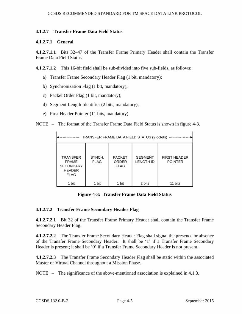
CCSDS RECOMMENDED STANDARD FOR TM SPACE DATA LINK PROTOCOL
CCSDS 132.0-B-2 Page 4-5 September 2015
4.1.2.7 Transfer Frame Data Field Status
4.1.2.7.1 General
4.1.2.7.1.1 Bits 32–47 of the Transfer Frame Primary Header shall contain the Transfer Frame Data Field Status.
4.1.2.7.1.2 This 16-bit field shall be sub-divided into five sub-fields, as follows:
a) Transfer Frame Secondary Header Flag (1 bit, mandatory);
b) Synchronization Flag (1 bit, mandatory);
c) Packet Order Flag (1 bit, mandatory);
d) Segment Length Identifier (2 bits, mandatory);
e) First Header Pointer (11 bits, mandatory).
NOTE – The format of the Transfer Frame Data Field Status is shown in figure 4-3.
PACKETORDERFLAG
SEGMENTLENGTH ID
TRANSFERFRAME
SECONDARYHEADER
FLAG
FIRST HEADERPOINTER
2 bits
TRANSFER FRAME DATA FIELD STATUS (2 octets)
SYNCH.FLAG
1 bit 1 bit 11 bits1 bit
Figure 4-3: Transfer Frame Data Field Status
4.1.2.7.2 Transfer Frame Secondary Header Flag
4.1.2.7.2.1 Bit 32 of the Transfer Frame Primary Header shall contain the Transfer Frame Secondary Header Flag.
4.1.2.7.2.2 The Transfer Frame Secondary Header Flag shall signal the presence or absence of the Transfer Frame Secondary Header. It shall be ‘1’ if a Transfer Frame Secondary Header is present; it shall be ‘0’ if a Transfer Frame Secondary Header is not present.
4.1.2.7.2.3 The Transfer Frame Secondary Header Flag shall be static within the associated Master or Virtual Channel throughout a Mission Phase.
NOTE – The significance of the above-mentioned association is explained in 4.1.3.

CCSDS RECOMMENDED STANDARD FOR TM SPACE DATA LINK PROTOCOL
CCSDS 132.0-B-2 Page 4-6 September 2015
4.1.2.7.3 Synchronization Flag
4.1.2.7.3.1 Bit 33 of the Transfer Frame Primary Header shall contain the Synchronization Flag.
4.1.2.7.3.2 The Synchronization Flag shall signal the type of data which are inserted into the Transfer Frame Data Field. It shall be ‘0’ if octet-synchronized and forward-ordered Packets or Idle Data are inserted; it shall be ‘1’ if a VCA_SDU is inserted.
4.1.2.7.3.3 The Synchronization Flag shall be static within a specific Virtual Channel throughout a Mission Phase.
4.1.2.7.4 Packet Order Flag
Bit 34 of the Transfer Frame Primary Header shall contain the Packet Order Flag.
NOTE – If the Synchronization Flag is set to ‘0’, the Packet Order Flag is reserved for future use by the CCSDS and is set to ‘0’. If the Synchronization Flag is set to ‘1’, the use of the Packet Order Flag is undefined.
4.1.2.7.5 Segment Length Identifier
4.1.2.7.5.1 Bits 35 and 36 of the Transfer Frame Primary Header shall contain the Segment Length Identifier.
4.1.2.7.5.2 If the Synchronization Flag is set to ‘0’, the Segment Length Identifier shall be set to ‘11’.
NOTES
1 This Identifier was required for earlier versions of this Recommended Standard to allow for the use of Source Packet Segments, which are no longer defined. Its value has been set to the value used to denote non-use of Source Packet Segments in previous versions.
2 If the Synchronization Flag is set to ‘1’, then the Segment Length Identifier is undefined.
4.1.2.7.6 First Header Pointer
4.1.2.7.6.1 Bits 37–47 of the Transfer Frame Primary Header shall contain the First Header Pointer.
4.1.2.7.6.2 If the Synchronization Flag is set to ‘0’, the First Header Pointer shall contain the position of the first octet of the first Packet that starts in the Transfer Frame Data Field.
NOTE – If the Synchronization Flag is set to ‘1’, then the First Header Pointer is undefined.
CCSDS RECOMMENDED STANDARD FOR TM SPACE DATA LINK PROTOCOL
CCSDS 132.0-B-2 Page 4-7 September 2015
4.1.2.7.6.3 The locations of the octets in the Transfer Frame Data Field shall be numbered in ascending order. The first octet in this Field is assigned the number 0. The First Header Pointer shall contain the binary representation of the location of the first octet of the first Packet that starts in the Transfer Frame Data Field.
NOTES
1 The purpose of the First Header Pointer is to facilitate delimiting of variable-length Packets contained within the Transfer Frame Data Field by pointing directly to the location of the first Packet from which its length may be determined.
2 The locations of any subsequent Packets within the same Transfer Frame Data Field will be determined by calculating the locations using the length field of these Packets.
3 If the last Packet in the Transfer Frame Data Field of Transfer Frame N spills over into Frame M of the same Virtual Channel (N<M), the First Header Pointer in Frame M ignores the residue of the split Packet and indicates the start of the next Packet that starts in Frame M.
4.1.2.7.6.4 If no Packet starts in the Transfer Frame Data Field, the First Header Pointer shall be set to ‘11111111111’.
NOTE – The above situation may occur if a long Packet extends across more than one Transfer Frame.
4.1.2.7.6.5 If a Transfer Frame contains only Idle Data in its Transfer Frame Data Field, the First Header Pointer shall be set to ‘11111111110’.
NOTE – A Transfer Frame with its First Header Pointer set to ‘11111111110’ is called an Only Idle Data (OID) Transfer Frame, meaning that it has Only Idle Data in its Data Field (see 4.1.4.6).
4.1.3 TRANSFER FRAME SECONDARY HEADER
4.1.3.1 General
4.1.3.1.1 If present, the Transfer Frame Secondary Header shall follow, without gap, the Transfer Frame Primary Header.
4.1.3.1.2 The Transfer Frame Secondary Header is optional; its presence or absence shall be signaled by the Transfer Frame Secondary Header Flag in the Transfer Frame Primary Header (see 4.1.2.7.2).
4.1.3.1.3 The Transfer Frame Secondary Header shall consist of an integral number of octets as follows:
a) Transfer Frame Secondary Header Identification Field (1 octet, mandatory);
b) Transfer Frame Secondary Header Data Field (1 to 63 octets, mandatory).
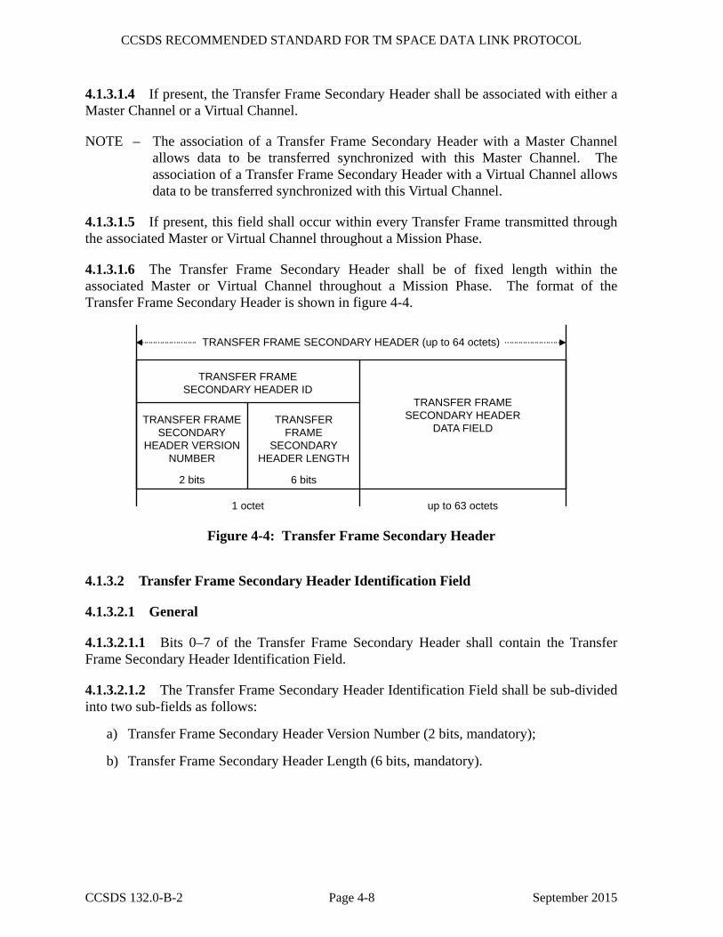
CCSDS RECOMMENDED STANDARD FOR TM SPACE DATA LINK PROTOCOL
CCSDS 132.0-B-2 Page 4-8 September 2015
4.1.3.1.4 If present, the Transfer Frame Secondary Header shall be associated with either a Master Channel or a Virtual Channel.
NOTE – The association of a Transfer Frame Secondary Header with a Master Channel allows data to be transferred synchronized with this Master Channel. The association of a Transfer Frame Secondary Header with a Virtual Channel allows data to be transferred synchronized with this Virtual Channel.
4.1.3.1.5 If present, this field shall occur within every Transfer Frame transmitted through the associated Master or Virtual Channel throughout a Mission Phase.
4.1.3.1.6 The Transfer Frame Secondary Header shall be of fixed length within the associated Master or Virtual Channel throughout a Mission Phase. The format of the Transfer Frame Secondary Header is shown in figure 4-4.
TRANSFER FRAMESECONDARY
HEADER VERSIONNUMBER
TRANSFER FRAMESECONDARY HEADER ID
TRANSFER FRAMESECONDARY HEADER
DATA FIELD
up to 63 octets
TRANSFERFRAME
SECONDARYHEADER LENGTH
6 bits2 bits
1 octet
TRANSFER FRAME SECONDARY HEADER (up to 64 octets)
Figure 4-4: Transfer Frame Secondary Header
4.1.3.2 Transfer Frame Secondary Header Identification Field
4.1.3.2.1 General
4.1.3.2.1.1 Bits 0–7 of the Transfer Frame Secondary Header shall contain the Transfer Frame Secondary Header Identification Field.
4.1.3.2.1.2 The Transfer Frame Secondary Header Identification Field shall be sub-divided into two sub-fields as follows:
a) Transfer Frame Secondary Header Version Number (2 bits, mandatory);
b) Transfer Frame Secondary Header Length (6 bits, mandatory).
CCSDS RECOMMENDED STANDARD FOR TM SPACE DATA LINK PROTOCOL
CCSDS 132.0-B-2 Page 4-9 September 2015
4.1.3.2.2 Transfer Frame Secondary Header Version Number
4.1.3.2.2.1 Bits 0–1 of the Transfer Frame Secondary Header shall contain the (Binary Encoded) Transfer Frame Secondary Header Version Number.
4.1.3.2.2.2 The Transfer Frame Secondary Header Version Number shall be set to ‘00’.
NOTE – This sub-field indicates which of up to four Secondary Header versions is used. The present Recommended Standard recognizes only one version, which is Version 1, the binary encoded Version Number of which is ‘00’.
4.1.3.2.3 Transfer Frame Secondary Header Length
4.1.3.2.3.1 Bits 2–7 of the Transfer Frame Secondary Header shall contain the Transfer Frame Secondary Header Length.
4.1.3.2.3.2 This sub-field shall contain the total length of the Transfer Frame Secondary Header in octets minus one, represented as a binary number.
4.1.3.2.3.3 The Transfer Frame Secondary Header Length shall be static within the associated Master or Virtual Channel throughout a Mission Phase.
NOTE – When a Secondary Header is present, this length may be used to compute the location of the start of the field following the Secondary Header.
4.1.3.3 Transfer Frame Secondary Header Data Field
4.1.3.3.1 The Transfer Frame Secondary Header Data Field shall follow, without gap, the Transfer Frame Secondary Header Identification Field.
4.1.3.3.2 The Transfer Frame Secondary Header Data Field shall contain the Transfer Frame Secondary Header data.
4.1.3.3.3 The Transfer Frame Secondary Header Data Field shall be of fixed length within the associated Master or Virtual Channel throughout a Mission Phase.
4.1.4 TRANSFER FRAME DATA FIELD
4.1.4.1 The Transfer Frame Data Field shall follow, without gap, the Transfer Frame Primary Header or the Transfer Frame Secondary Header if present.
4.1.4.2 The Transfer Frame Data Field, which shall contain an integer number of octets, has a length which varies and is equal to:
a) the fixed Transfer Frame length which has been selected for use on a particular Physical Channel; minus
b) the length of the Transfer Frame Primary Header plus the length of the Transfer Frame Secondary Header and/or the Transfer Frame Trailer (if any of these are present).
CCSDS RECOMMENDED STANDARD FOR TM SPACE DATA LINK PROTOCOL
CCSDS 132.0-B-2 Page 4-10 September 2015
4.1.4.3 The Transfer Frame Data Field shall contain Packets, one VCA_SDU, or Idle Data.
4.1.4.4 VCA_SDUs shall not be mixed with Packets on the same Virtual Channel. Idle Data shall be transferred on a Virtual Channel that transfers Packets. Whether a particular Virtual Channel transfers Packets (and possibly Idle Data) or VCA_SDUs shall be established by management and static throughout a Mission Phase.
4.1.4.5 If Packets are contained in the Transfer Frame Data Field, Packets shall be inserted contiguously and in forward order into the Transfer Frame Data Field.
NOTE – The first and last Packets of the Transfer Frame Data Field are not necessarily complete, since the first Packet may be a continuation of a Packet begun in the previous Transfer Frame, and the last Packet may continue in the subsequent Transfer Frame of the same Virtual Channel.
4.1.4.6 In the case where sufficient data (Packets including Idle Packets or a VCA_SDU) are not available to be inserted in a Transfer Frame Data Field at release time for a Transfer Frame, a Transfer Frame with a Data Field containing only Idle Data shall be transmitted. Such a Transfer Frame is called an OID (Only Idle Data in its Data Field) Transfer Frame. The First Header Pointer of an OID Transfer Frame shall be set to ‘11111111110’ (see 4.1.2.7.6) and a project-specified ‘idle’ pattern shall be inserted into the Transfer Frame Data Field. The VCID of an OID Transfer Frame shall be one of the VCIDs used for transferring Packets.
NOTES
1 The data field of an OID Frame contains only idle data, but the Transfer Frame Secondary Header or Operational Control Field can contain valid data depending upon the Virtual Channel.
2 OID Transfer Frames may be sent on Virtual Channels that also carry valid Packets, but it is preferred that a separate Virtual Channel be dedicated to carry OID Transfer Frames unless there is a need to send OID Transfer Frames on a specific Virtual Channel (e.g., to transmit data in the Transfer Frame Secondary Header and/or the Operational Control Field on a specific Virtual Channel).
3 An OID Transfer Frame can be generated whenever it is necessary (even in the middle of transmission of a Packet that is split into multiple Transfer Frames).
4 OID Data in the Transfer Frame Data Field of an OID Transfer Frame should not be confused with the Idle Packet specified in reference [8].
5 The idle pattern used in the OID Transfer Frame is project specific, but a random pattern is preferred. Problems with the reception of frames have been encountered because of insufficient randomization.
CCSDS RECOMMENDED STANDARD FOR TM SPACE DATA LINK PROTOCOL
CCSDS 132.0-B-2 Page 4-11 September 2015
4.1.5 OPERATIONAL CONTROL FIELD
4.1.5.1 If present, the Operational Control Field shall occupy the four octets following, without gap, the Transfer Frame Data Field.
NOTE – The Operational Control Field is optional; its presence or absence is signaled by the Operational Control Field Flag in the Transfer Frame Primary Header (see 4.1.2.4).
4.1.5.2 If present, the Operational Control Field shall be associated with either a Master Channel or a Virtual Channel.
NOTE – The association of an Operational Control Field with a Master Channel allows data to be transferred synchronized with this Master Channel. The association of an Operational Control Field with a Virtual Channel allows data to be transferred synchronized with this Virtual Channel.
4.1.5.3 If present, this field shall occur within every Transfer Frame transmitted through the associated Master or Virtual Channel throughout a Mission Phase.
4.1.5.4 Bit 0 of the Operational Control Field shall contain a Type Flag with the following meanings:
a) the Type Flag shall be ‘0’ if the Operational Control Field holds a Type-1-Report which shall contain a Communications Link Control Word, the content of which is defined in reference [B6];
b) the Type Flag shall be ‘1’ if the Operational Control Field holds a Type-2-Report.
NOTE – The Type Flag may vary between Transfer Frames on the same Master or Virtual Channel that carries this field.
4.1.5.5 In a Type-2 Report, bit 1 of the Operational Control Field shall indicate the use of this report as follows:
a) if this bit is ‘0’, the contents of the report are project-specific;
b) if this bit is ‘1’, the contents of the report are reserved by CCSDS for future application.
NOTES
1 In Type-2 Reports, the value of bit 1 of the Operational Control Field can vary between Transfer Frames on the same Virtual Channel that carries this field.
2 The purpose of this field is to provide a standardized mechanism for reporting a small number of real-time functions (such as retransmission control or spacecraft clock calibration); currently the use for retransmission control (Type-1 Reports) has been defined by CCSDS in reference [B6]. This issue of the Recommended Standard does not define the use of Type-2 Reports; however, it reserves the possibility to do so in future issues by restricting the utilization of bit 1 of the Operational Control Field.
CCSDS RECOMMENDED STANDARD FOR TM SPACE DATA LINK PROTOCOL
CCSDS 132.0-B-2 Page 4-12 September 2015
4.1.6 FRAME ERROR CONTROL FIELD
4.1.6.1 General
4.1.6.1.1 If present, the Frame Error Control Field shall occupy the two octets following, without gap, the Operational Control Field if this is present, or the Transfer Frame Data Field, if an Operational Control Field is not present.
4.1.6.1.2 The Frame Error Control Field is optional; its presence or absence shall be established by management.
4.1.6.1.3 If present, the Frame Error Control Field shall occur within every Transfer Frame transmitted within the same Physical Channel throughout a Mission Phase.
NOTES
1 The purpose of this field is to provide a capability for detecting errors which may have been introduced into the Transfer Frame during the transmission and data handling process.
2 Whether this field should be used on a particular Physical Channel is determined based on the mission requirements for data quality and the selected options for the underlying Channel Coding Sublayer. This field may be mandatory depending on the selected options for the Channel Coding Sublayer.
4.1.6.2 Frame Error Control Field Encoding Procedure
4.1.6.2.1 The Frame Error Control Field is computed by applying Cyclic Redundancy Check (CRC) techniques. The Encoding Procedure shall accept an (n–16)-bit Transfer Frame, excluding the Frame Error Control Field, and generate a systematic binary (n,n–16) block code by appending a 16-bit Frame Error Control Field as the final 16 bits of the codeblock, where n is the length of the Transfer Frame.
NOTE – The Bit Numbering Convention as specified in 1.6.2 is applicable below.
4.1.6.2.2 The equation for the contents of the Frame Error Control Field is:
FECF = [(X16 · M(X)) + (X(n–16) · L(X))] modulo G(X)
= P0 · X15 + P1 · X14 + P2 · X13 + … + P14 · X1 + P15 · X0
where
– all arithmetic is modulo 2;
– FECF is the 16-bit Frame Error Control Field with the first bit transferred being the most significant bit P0 taken as the coefficient of the highest power of X;
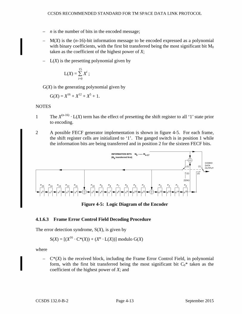
CCSDS RECOMMENDED STANDARD FOR TM SPACE DATA LINK PROTOCOL
CCSDS 132.0-B-2 Page 4-13 September 2015
– n is the number of bits in the encoded message;
– M(X) is the (n-16)-bit information message to be encoded expressed as a polynomial with binary coefficients, with the first bit transferred being the most significant bit M0 taken as the coefficient of the highest power of X;
– L(X) is the presetting polynomial given by
L(X) = ∑i=0
15 Xi ;
G(X) is the generating polynomial given by
G(X) = X16 + X12 + X5 + 1.
NOTES
1 The X(n-16) · L(X) term has the effect of presetting the shift register to all ‘1’ state prior to encoding.
2 A possible FECF generator implementation is shown in figure 4-5. For each frame, the shift register cells are initialized to ‘1’. The ganged switch is in position 1 while the information bits are being transferred and in position 2 for the sixteen FECF bits.
(M0 transferred first)INFORMATION BITS M0 Mn-17
X0 X1 X2 X3 X4 X5 X6 X7 X8 X9 X10 X11 X12 X13 X14 X15
P15 P14 P13 P12 P11 P10 P9 P8 P7 P6 P5 P4 P3 P2 P1 P0
ZERO
(1) (1)
(2) (2)
CODEDDATAOUTPUT
Figure 4-5: Logic Diagram of the Encoder
4.1.6.3 Frame Error Control Field Decoding Procedure
The error detection syndrome, S(X), is given by
S(X) = [(X16 · C*(X)) + (Xn · L(X))] modulo G(X)
where
– C*(X) is the received block, including the Frame Error Control Field, in polynomial form, with the first bit transferred being the most significant bit C0* taken as the coefficient of the highest power of X; and
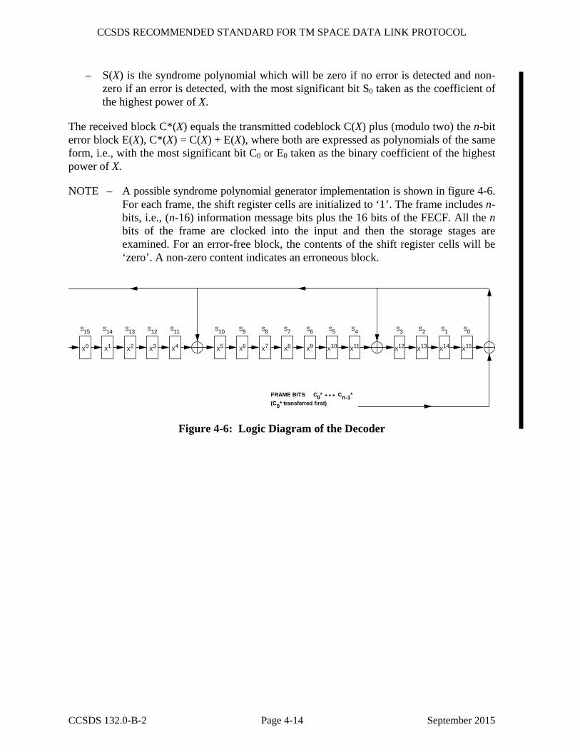
CCSDS RECOMMENDED STANDARD FOR TM SPACE DATA LINK PROTOCOL
CCSDS 132.0-B-2 Page 4-14 September 2015
– S(X) is the syndrome polynomial which will be zero if no error is detected and non-zero if an error is detected, with the most significant bit S0 taken as the coefficient of the highest power of X.
The received block C*(X) equals the transmitted codeblock C(X) plus (modulo two) the n-bit error block E(X), C*(X) = C(X) + E(X), where both are expressed as polynomials of the same form, i.e., with the most significant bit C0 or E0 taken as the binary coefficient of the highest power of X.
NOTE – A possible syndrome polynomial generator implementation is shown in figure 4-6. For each frame, the shift register cells are initialized to ‘1’. The frame includes n-bits, i.e., (n-16) information message bits plus the 16 bits of the FECF. All the n bits of the frame are clocked into the input and then the storage stages are examined. For an error-free block, the contents of the shift register cells will be ‘zero’. A non-zero content indicates an erroneous block.
(C0* transferred first)FRAME BITS C0* Cn-1*
X0 X1 X2 X3 X4 X5 X6 X7 X8 X9 X10 X11 X12 X13 X14 X15
S15 S14 S13 S12 S11 S10 S9 S8 S7 S6 S5 S4 S3 S2 S1 S0
Figure 4-6: Logic Diagram of the Decoder
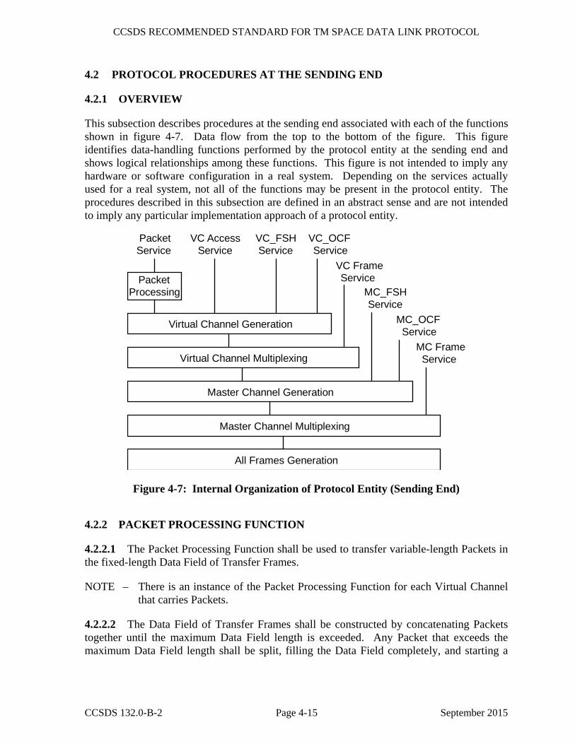
CCSDS RECOMMENDED STANDARD FOR TM SPACE DATA LINK PROTOCOL
CCSDS 132.0-B-2 Page 4-15 September 2015
4.2 PROTOCOL PROCEDURES AT THE SENDING END
4.2.1 OVERVIEW
This subsection describes procedures at the sending end associated with each of the functions shown in figure 4-7. Data flow from the top to the bottom of the figure. This figure identifies data-handling functions performed by the protocol entity at the sending end and shows logical relationships among these functions. This figure is not intended to imply any hardware or software configuration in a real system. Depending on the services actually used for a real system, not all of the functions may be present in the protocol entity. The procedures described in this subsection are defined in an abstract sense and are not intended to imply any particular implementation approach of a protocol entity.
MC FrameService
VC FrameService
MC_OCFService
MC_FSHService
PacketService
VC AccessService
Virtual Channel Multiplexing
Virtual Channel Generation
PacketProcessing
Master Channel Generation
Master Channel Multiplexing
All Frames Generation
VC_FSHService
VC_OCFService
Figure 4-7: Internal Organization of Protocol Entity (Sending End)
4.2.2 PACKET PROCESSING FUNCTION
4.2.2.1 The Packet Processing Function shall be used to transfer variable-length Packets in the fixed-length Data Field of Transfer Frames.
NOTE – There is an instance of the Packet Processing Function for each Virtual Channel that carries Packets.
4.2.2.2 The Data Field of Transfer Frames shall be constructed by concatenating Packets together until the maximum Data Field length is exceeded. Any Packet that exceeds the maximum Data Field length shall be split, filling the Data Field completely, and starting a
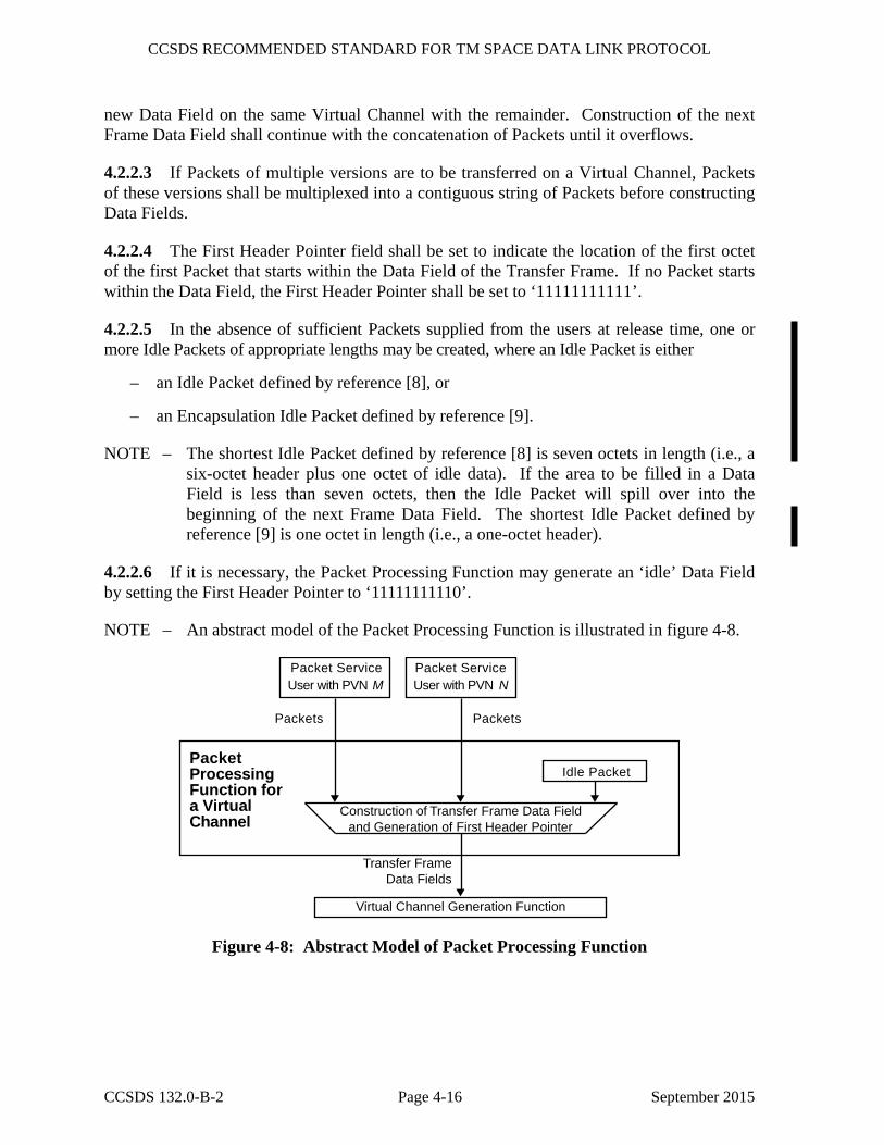
CCSDS RECOMMENDED STANDARD FOR TM SPACE DATA LINK PROTOCOL
CCSDS 132.0-B-2 Page 4-16 September 2015
new Data Field on the same Virtual Channel with the remainder. Construction of the next Frame Data Field shall continue with the concatenation of Packets until it overflows.
4.2.2.3 If Packets of multiple versions are to be transferred on a Virtual Channel, Packets of these versions shall be multiplexed into a contiguous string of Packets before constructing Data Fields.
4.2.2.4 The First Header Pointer field shall be set to indicate the location of the first octet of the first Packet that starts within the Data Field of the Transfer Frame. If no Packet starts within the Data Field, the First Header Pointer shall be set to ‘11111111111’.
4.2.2.5 In the absence of sufficient Packets supplied from the users at release time, one or more Idle Packets of appropriate lengths may be created, where an Idle Packet is either
– an Idle Packet defined by reference [8], or
– an Encapsulation Idle Packet defined by reference [9].
NOTE – The shortest Idle Packet defined by reference [8] is seven octets in length (i.e., a six-octet header plus one octet of idle data). If the area to be filled in a Data Field is less than seven octets, then the Idle Packet will spill over into the beginning of the next Frame Data Field. The shortest Idle Packet defined by reference [9] is one octet in length (i.e., a one-octet header).
4.2.2.6 If it is necessary, the Packet Processing Function may generate an ‘idle’ Data Field by setting the First Header Pointer to ‘11111111110’.
NOTE – An abstract model of the Packet Processing Function is illustrated in figure 4-8.
Transfer FrameData Fields
Packet ServiceUser with PVN M
PacketProcessingFunction fora VirtualChannel
Construction of Transfer Frame Data Fieldand Generation of First Header Pointer
PacketsPackets
Idle Packet
Virtual Channel Generation Function
Packet ServiceUser with PVN N
Figure 4-8: Abstract Model of Packet Processing Function

CCSDS RECOMMENDED STANDARD FOR TM SPACE DATA LINK PROTOCOL
CCSDS 132.0-B-2 Page 4-17 September 2015
4.2.3 VIRTUAL CHANNEL GENERATION FUNCTION
NOTE – The Virtual Channel Generation Function is used to build the basic structure of Transfer Frames. It is also used to build the structure and the Primary Header of the Transfer Frames for transmission on each Virtual Channel. There is an instance of the Virtual Channel Generation Function for each Virtual Channel.
4.2.3.1 Transfer Frames shall be assembled by:
a) placing a Transfer Frame Data Field (received from the Packet Processing Function) or a VCA_SDU (received from the VCA Service user) into the Transfer Frame Data Field; and
b) generating the Transfer Frame Primary Header fields.
4.2.3.2 A Virtual Channel Frame Count shall be generated independently for each Virtual Channel and placed into the Primary Header.
4.2.3.3 If there is a user of the VC_FSH Service for a particular Virtual Channel, an FSH_SDU supplied by the user shall be placed in the Transfer Frame Secondary Header. If there is a user of the VC_OCF Service for a particular Virtual Channel, an OCF_SDU supplied by the user shall be placed in the Operational Control Field.
The Master Channel Frame Count field of Transfer Frames shall be kept empty by the Virtual Channel Generation Function. The following fields of Transfer Frames, if present for the particular Physical or Master Channel, shall also be kept empty by the Virtual Channel Generation Function:
a) MC_FSH;
b) MC_OCF; and
c) Frame Error Control Field.
NOTE – An abstract model of the Virtual Channel Generation Function is illustrated in figure 4-9.
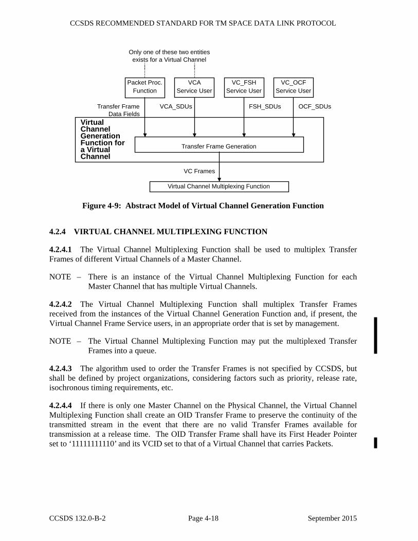
CCSDS RECOMMENDED STANDARD FOR TM SPACE DATA LINK PROTOCOL
CCSDS 132.0-B-2 Page 4-18 September 2015
Transfer FrameData Fields
VC Frames
Packet Proc.Function
VirtualChannelGenerationFunction fora VirtualChannel
Only one of these two entitiesexists for a Virtual Channel
VCA_SDUs
Transfer Frame Generation
VC_FSHService User
VC_OCFService User
VCAService User
Virtual Channel Multiplexing Function
FSH_SDUs OCF_SDUs
Figure 4-9: Abstract Model of Virtual Channel Generation Function
4.2.4 VIRTUAL CHANNEL MULTIPLEXING FUNCTION
4.2.4.1 The Virtual Channel Multiplexing Function shall be used to multiplex Transfer Frames of different Virtual Channels of a Master Channel.
NOTE – There is an instance of the Virtual Channel Multiplexing Function for each Master Channel that has multiple Virtual Channels.
4.2.4.2 The Virtual Channel Multiplexing Function shall multiplex Transfer Frames received from the instances of the Virtual Channel Generation Function and, if present, the Virtual Channel Frame Service users, in an appropriate order that is set by management.
NOTE – The Virtual Channel Multiplexing Function may put the multiplexed Transfer Frames into a queue.
4.2.4.3 The algorithm used to order the Transfer Frames is not specified by CCSDS, but shall be defined by project organizations, considering factors such as priority, release rate, isochronous timing requirements, etc.
4.2.4.4 If there is only one Master Channel on the Physical Channel, the Virtual Channel Multiplexing Function shall create an OID Transfer Frame to preserve the continuity of the transmitted stream in the event that there are no valid Transfer Frames available for transmission at a release time. The OID Transfer Frame shall have its First Header Pointer set to ‘11111111110’ and its VCID set to that of a Virtual Channel that carries Packets.
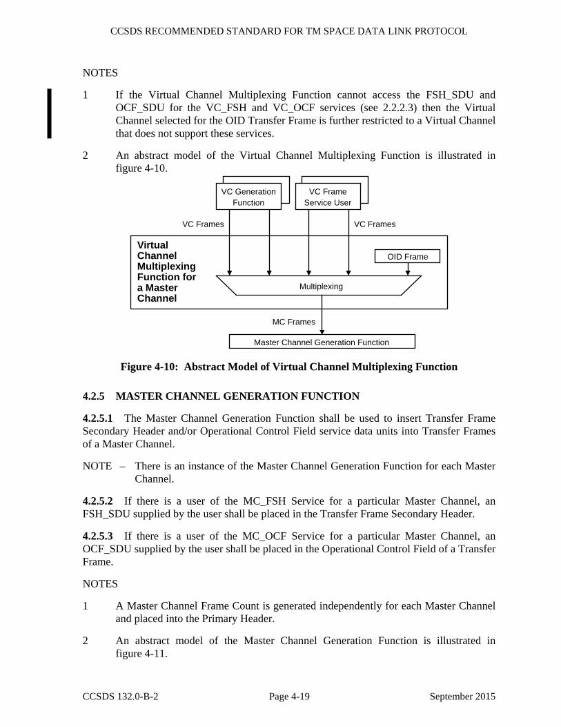
CCSDS RECOMMENDED STANDARD FOR TM SPACE DATA LINK PROTOCOL
CCSDS 132.0-B-2 Page 4-19 September 2015
NOTES
1 If the Virtual Channel Multiplexing Function cannot access the FSH_SDU and OCF_SDU for the VC_FSH and VC_OCF services (see 2.2.2.3) then the Virtual Channel selected for the OID Transfer Frame is further restricted to a Virtual Channel that does not support these services.
2 An abstract model of the Virtual Channel Multiplexing Function is illustrated in figure 4-10.
VC Frames
MC Frames
VC GenerationFunction
VirtualChannelMultiplexingFunction fora MasterChannel
VC Frames
Multiplexing
OID Frame
Master Channel Generation Function
VC FrameService User
Figure 4-10: Abstract Model of Virtual Channel Multiplexing Function
4.2.5 MASTER CHANNEL GENERATION FUNCTION
4.2.5.1 The Master Channel Generation Function shall be used to insert Transfer Frame Secondary Header and/or Operational Control Field service data units into Transfer Frames of a Master Channel.
NOTE – There is an instance of the Master Channel Generation Function for each Master Channel.
4.2.5.2 If there is a user of the MC_FSH Service for a particular Master Channel, an FSH_SDU supplied by the user shall be placed in the Transfer Frame Secondary Header.
4.2.5.3 If there is a user of the MC_OCF Service for a particular Master Channel, an OCF_SDU supplied by the user shall be placed in the Operational Control Field of a Transfer Frame.
NOTES
1 A Master Channel Frame Count is generated independently for each Master Channel and placed into the Primary Header.
2 An abstract model of the Master Channel Generation Function is illustrated in figure 4-11.
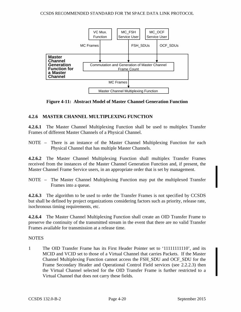
CCSDS RECOMMENDED STANDARD FOR TM SPACE DATA LINK PROTOCOL
CCSDS 132.0-B-2 Page 4-20 September 2015
MC Frames
MC Frames
VC Mux.Function
MasterChannelGenerationFunction fora MasterChannel
Commutation and Generation of Master ChannelFrame Count
MC_FSHService User
MC_OCFService User
Master Channel Multiplexing Function
FSH_SDUs OCF_SDUs
Figure 4-11: Abstract Model of Master Channel Generation Function
4.2.6 MASTER CHANNEL MULTIPLEXING FUNCTION
4.2.6.1 The Master Channel Multiplexing Function shall be used to multiplex Transfer Frames of different Master Channels of a Physical Channel.
NOTE – There is an instance of the Master Channel Multiplexing Function for each Physical Channel that has multiple Master Channels.
4.2.6.2 The Master Channel Multiplexing Function shall multiplex Transfer Frames received from the instances of the Master Channel Generation Function and, if present, the Master Channel Frame Service users, in an appropriate order that is set by management.
NOTE – The Master Channel Multiplexing Function may put the multiplexed Transfer Frames into a queue.
4.2.6.3 The algorithm to be used to order the Transfer Frames is not specified by CCSDS but shall be defined by project organizations considering factors such as priority, release rate, isochronous timing requirements, etc.
4.2.6.4 The Master Channel Multiplexing Function shall create an OID Transfer Frame to preserve the continuity of the transmitted stream in the event that there are no valid Transfer Frames available for transmission at a release time.
NOTES
1 The OID Transfer Frame has its First Header Pointer set to ‘11111111110’, and its MCID and VCID set to those of a Virtual Channel that carries Packets. If the Master Channel Multiplexing Function cannot access the FSH_SDU and OCF_SDU for the Frame Secondary Header and Operational Control Field services (see 2.2.2.3) then the Virtual Channel selected for the OID Transfer Frame is further restricted to a Virtual Channel that does not carry these fields.
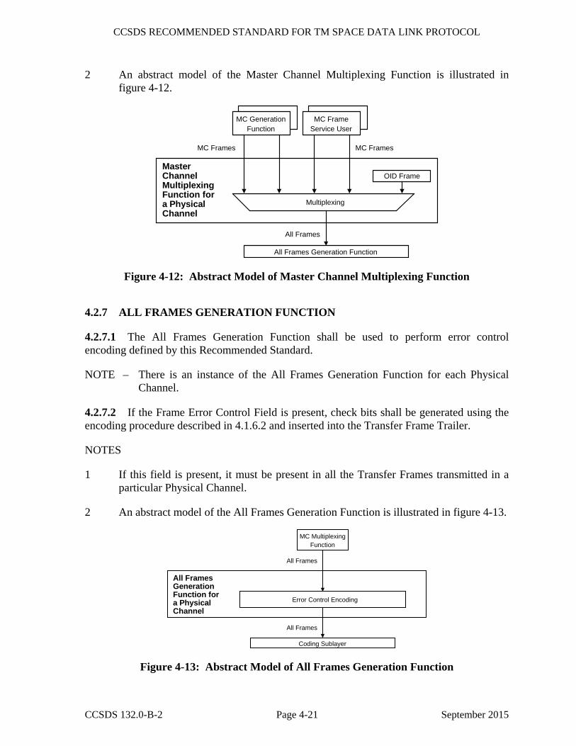
CCSDS RECOMMENDED STANDARD FOR TM SPACE DATA LINK PROTOCOL
CCSDS 132.0-B-2 Page 4-21 September 2015
2 An abstract model of the Master Channel Multiplexing Function is illustrated in figure 4-12.
MC Frames
All Frames
MC GenerationFunction
MasterChannelMultiplexingFunction fora PhysicalChannel
MC Frames
Multiplexing
OID Frame
All Frames Generation Function
MC FrameService User
Figure 4-12: Abstract Model of Master Channel Multiplexing Function
4.2.7 ALL FRAMES GENERATION FUNCTION
4.2.7.1 The All Frames Generation Function shall be used to perform error control encoding defined by this Recommended Standard.
NOTE – There is an instance of the All Frames Generation Function for each Physical Channel.
4.2.7.2 If the Frame Error Control Field is present, check bits shall be generated using the encoding procedure described in 4.1.6.2 and inserted into the Transfer Frame Trailer.
NOTES
1 If this field is present, it must be present in all the Transfer Frames transmitted in a particular Physical Channel.
2 An abstract model of the All Frames Generation Function is illustrated in figure 4-13.
All Frames
All Frames
MC MultiplexingFunction
All FramesGenerationFunction fora PhysicalChannel
Error Control Encoding
Coding Sublayer
Figure 4-13: Abstract Model of All Frames Generation Function
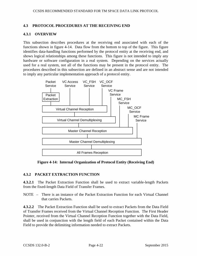
CCSDS RECOMMENDED STANDARD FOR TM SPACE DATA LINK PROTOCOL
CCSDS 132.0-B-2 Page 4-22 September 2015
4.3 PROTOCOL PROCEDURES AT THE RECEIVING END
4.3.1 OVERVIEW
This subsection describes procedures at the receiving end associated with each of the functions shown in figure 4-14. Data flow from the bottom to top of the figure. This figure identifies data-handling functions performed by the protocol entity at the receiving end, and shows logical relationships among these functions. This figure is not intended to imply any hardware or software configuration in a real system. Depending on the services actually used for a real system, not all of the functions may be present in the protocol entity. The procedures described in this subsection are defined in an abstract sense and are not intended to imply any particular implementation approach of a protocol entity.
MC FrameService
VC FrameService
MC_OCFService
MC_FSHService
PacketService
VC AccessService
Virtual Channel Demultiplexing
Virtual Channel Reception
PacketExtraction
Master Channel Reception
Master Channel Demultiplexing
All Frames Reception
VC_FSHService
VC_OCFService
Figure 4-14: Internal Organization of Protocol Entity (Receiving End)
4.3.2 PACKET EXTRACTION FUNCTION
4.3.2.1 The Packet Extraction Function shall be used to extract variable-length Packets from the fixed-length Data Field of Transfer Frames.
NOTE – There is an instance of the Packet Extraction Function for each Virtual Channel that carries Packets.
4.3.2.2 The Packet Extraction Function shall be used to extract Packets from the Data Field of Transfer Frames received from the Virtual Channel Reception Function. The First Header Pointer, received from the Virtual Channel Reception Function together with the Data Field, shall be used in conjunction with the length field of each Packet contained within the Data Field to provide the delimiting information needed to extract Packets.
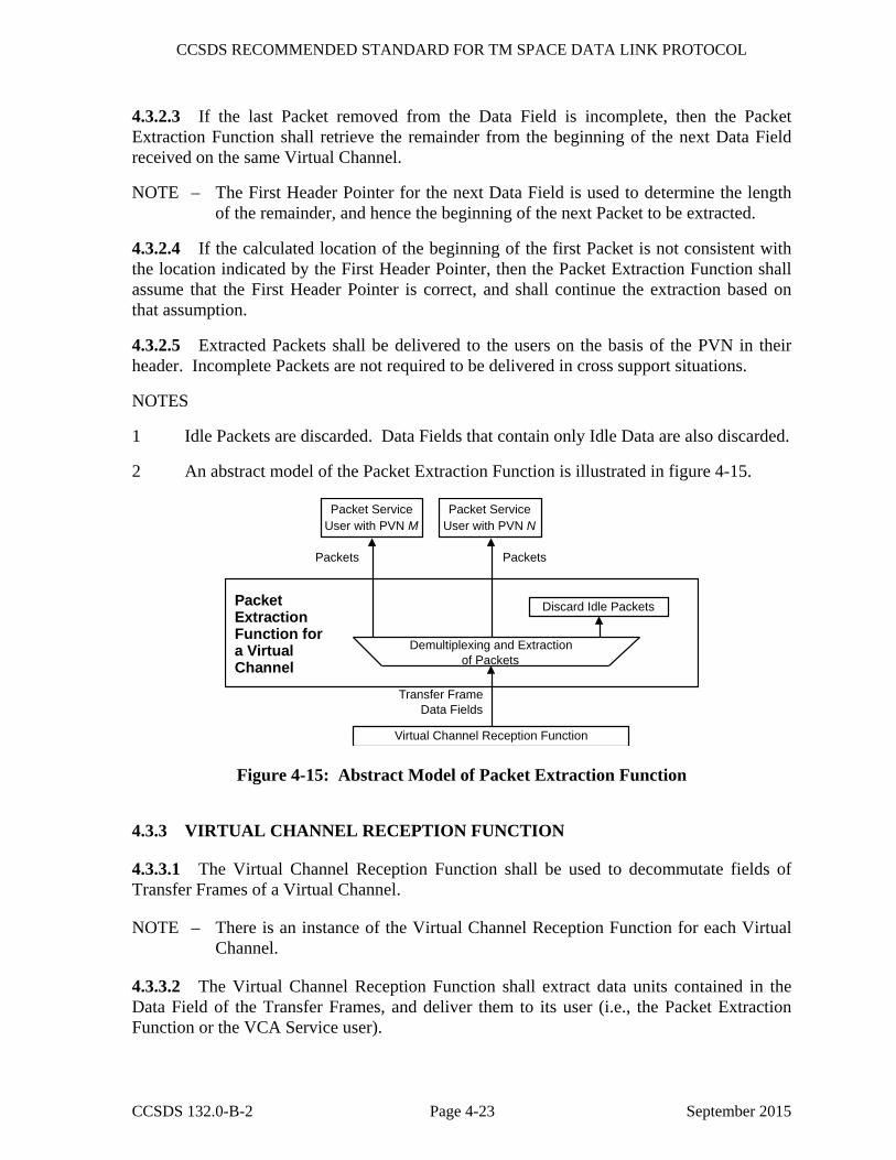
CCSDS RECOMMENDED STANDARD FOR TM SPACE DATA LINK PROTOCOL
CCSDS 132.0-B-2 Page 4-23 September 2015
4.3.2.3 If the last Packet removed from the Data Field is incomplete, then the Packet Extraction Function shall retrieve the remainder from the beginning of the next Data Field received on the same Virtual Channel.
NOTE – The First Header Pointer for the next Data Field is used to determine the length of the remainder, and hence the beginning of the next Packet to be extracted.
4.3.2.4 If the calculated location of the beginning of the first Packet is not consistent with the location indicated by the First Header Pointer, then the Packet Extraction Function shall assume that the First Header Pointer is correct, and shall continue the extraction based on that assumption.
4.3.2.5 Extracted Packets shall be delivered to the users on the basis of the PVN in their header. Incomplete Packets are not required to be delivered in cross support situations.
NOTES
1 Idle Packets are discarded. Data Fields that contain only Idle Data are also discarded.
2 An abstract model of the Packet Extraction Function is illustrated in figure 4-15.
Transfer FrameData Fields
Packet ServiceUser with PVN M
PacketExtractionFunction fora VirtualChannel
PacketsPackets
Demultiplexing and Extractionof Packets
Discard Idle Packets
Packet ServiceUser with PVN N
Virtual Channel Reception Function
Figure 4-15: Abstract Model of Packet Extraction Function
4.3.3 VIRTUAL CHANNEL RECEPTION FUNCTION
4.3.3.1 The Virtual Channel Reception Function shall be used to decommutate fields of Transfer Frames of a Virtual Channel.
NOTE – There is an instance of the Virtual Channel Reception Function for each Virtual Channel.
4.3.3.2 The Virtual Channel Reception Function shall extract data units contained in the Data Field of the Transfer Frames, and deliver them to its user (i.e., the Packet Extraction Function or the VCA Service user).
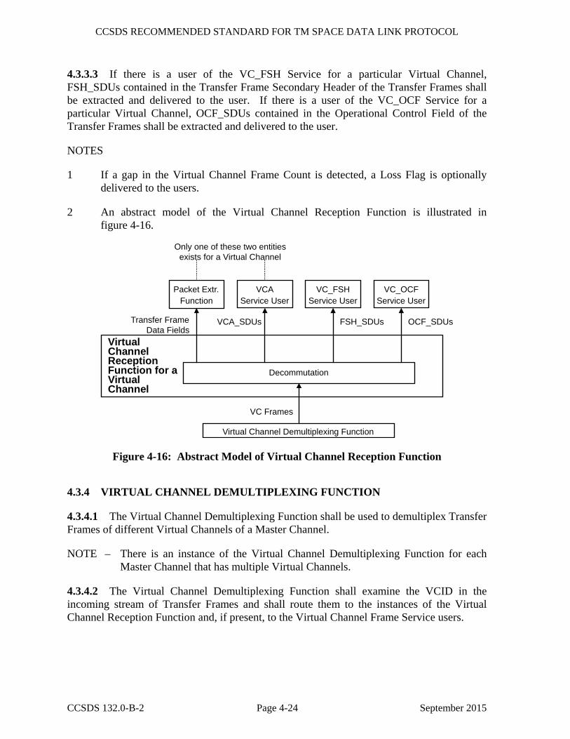
CCSDS RECOMMENDED STANDARD FOR TM SPACE DATA LINK PROTOCOL
CCSDS 132.0-B-2 Page 4-24 September 2015
4.3.3.3 If there is a user of the VC_FSH Service for a particular Virtual Channel, FSH_SDUs contained in the Transfer Frame Secondary Header of the Transfer Frames shall be extracted and delivered to the user. If there is a user of the VC_OCF Service for a particular Virtual Channel, OCF_SDUs contained in the Operational Control Field of the Transfer Frames shall be extracted and delivered to the user.
NOTES
1 If a gap in the Virtual Channel Frame Count is detected, a Loss Flag is optionally delivered to the users.
2 An abstract model of the Virtual Channel Reception Function is illustrated in figure 4-16.
Transfer FrameData Fields
VC Frames
Packet Extr.Function
VirtualChannelReceptionFunction for aVirtualChannel
Only one of these two entitiesexists for a Virtual Channel
VCA_SDUs
Decommutation
VC_FSHService User
VC_OCFService User
VCAService User
Virtual Channel Demultiplexing Function
FSH_SDUs OCF_SDUs
Figure 4-16: Abstract Model of Virtual Channel Reception Function
4.3.4 VIRTUAL CHANNEL DEMULTIPLEXING FUNCTION
4.3.4.1 The Virtual Channel Demultiplexing Function shall be used to demultiplex Transfer Frames of different Virtual Channels of a Master Channel.
NOTE – There is an instance of the Virtual Channel Demultiplexing Function for each Master Channel that has multiple Virtual Channels.
4.3.4.2 The Virtual Channel Demultiplexing Function shall examine the VCID in the incoming stream of Transfer Frames and shall route them to the instances of the Virtual Channel Reception Function and, if present, to the Virtual Channel Frame Service users.
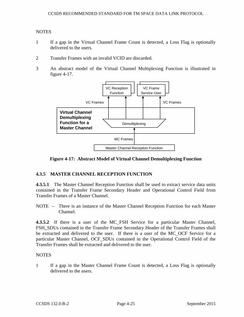
CCSDS RECOMMENDED STANDARD FOR TM SPACE DATA LINK PROTOCOL
CCSDS 132.0-B-2 Page 4-25 September 2015
NOTES
1 If a gap in the Virtual Channel Frame Count is detected, a Loss Flag is optionally delivered to the users.
2 Transfer Frames with an invalid VCID are discarded.
3 An abstract model of the Virtual Channel Multiplexing Function is illustrated in figure 4-17.
VC Frames
MC Frames
VC ReceptionFunction
Virtual ChannelDemultiplexingFunction for aMaster Channel
VC Frames
Demultiplexing
Master Channel Reception Function
VC FrameService User
Figure 4-17: Abstract Model of Virtual Channel Demultiplexing Function
4.3.5 MASTER CHANNEL RECEPTION FUNCTION
4.3.5.1 The Master Channel Reception Function shall be used to extract service data units contained in the Transfer Frame Secondary Header and Operational Control Field from Transfer Frames of a Master Channel.
NOTE – There is an instance of the Master Channel Reception Function for each Master Channel.
4.3.5.2 If there is a user of the MC_FSH Service for a particular Master Channel, FSH_SDUs contained in the Transfer Frame Secondary Header of the Transfer Frames shall be extracted and delivered to the user. If there is a user of the MC_OCF Service for a particular Master Channel, OCF_SDUs contained in the Operational Control Field of the Transfer Frames shall be extracted and delivered to the user.
NOTES
1 If a gap in the Master Channel Frame Count is detected, a Loss Flag is optionally delivered to the users.

CCSDS RECOMMENDED STANDARD FOR TM SPACE DATA LINK PROTOCOL
CCSDS 132.0-B-2 Page 4-26 September 2015
2 An abstract model of the Master Channel Reception Function is illustrated in figure 4-18.
MC Frames
MC Frames
VC Demux.Function
Master ChannelReceptionFunction for aMaster Channel
Decommutation
MC_FSHService User
MC_OCFService User
Master Channel Demultiplexing Function
FSH_SDUs OCF_SDUs
Figure 4-18: Abstract Model of Master Channel Reception Function
4.3.6 MASTER CHANNEL DEMULTIPLEXING FUNCTION
4.3.6.1 The Master Channel Demultiplexing Function shall be used to demultiplex Transfer Frames of different Master Channels of a Physical Channel.
NOTE – There is an instance of the Master Channel Demultiplexing Function for each Physical Channel that has multiple Master Channels.
4.3.6.2 The Master Channel Demultiplexing Function shall examine the MCID in the incoming stream of Transfer Frames and shall route them to the instances of the Master Channel Reception Function and, if present, to the Master Channel Frame Service users.
NOTES
1 If a gap in the Master Channel Frame Count is detected, a Loss Flag is optionally delivered to the users.
2 Transfer Frames with an invalid MCID are discarded.
3 An abstract model of the Master Channel Demultiplexing Function is illustrated in figure 4-19.
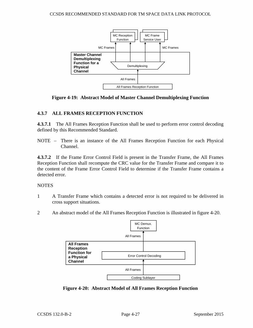
CCSDS RECOMMENDED STANDARD FOR TM SPACE DATA LINK PROTOCOL
CCSDS 132.0-B-2 Page 4-27 September 2015
MC Frames
All Frames
MC ReceptionFunction
Master ChannelDemultiplexingFunction for aPhysicalChannel
MC Frames
Demultiplexing
All Frames Reception Function
MC FrameService User
Figure 4-19: Abstract Model of Master Channel Demultiplexing Function
4.3.7 ALL FRAMES RECEPTION FUNCTION
4.3.7.1 The All Frames Reception Function shall be used to perform error control decoding defined by this Recommended Standard.
NOTE – There is an instance of the All Frames Reception Function for each Physical Channel.
4.3.7.2 If the Frame Error Control Field is present in the Transfer Frame, the All Frames Reception Function shall recompute the CRC value for the Transfer Frame and compare it to the content of the Frame Error Control Field to determine if the Transfer Frame contains a detected error.
NOTES
1 A Transfer Frame which contains a detected error is not required to be delivered in cross support situations.
2 An abstract model of the All Frames Reception Function is illustrated in figure 4-20.
All Frames
All Frames
MC Demux.Function
All FramesReceptionFunction fora PhysicalChannel
Error Control Decoding
Coding Sublayer
Figure 4-20: Abstract Model of All Frames Reception Function
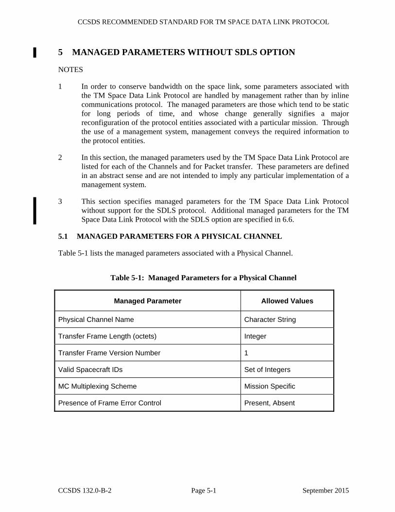
CCSDS RECOMMENDED STANDARD FOR TM SPACE DATA LINK PROTOCOL
CCSDS 132.0-B-2 Page 5-1 September 2015
5 MANAGED PARAMETERS WITHOUT SDLS OPTION
NOTES
1 In order to conserve bandwidth on the space link, some parameters associated with the TM Space Data Link Protocol are handled by management rather than by inline communications protocol. The managed parameters are those which tend to be static for long periods of time, and whose change generally signifies a major reconfiguration of the protocol entities associated with a particular mission. Through the use of a management system, management conveys the required information to the protocol entities.
2 In this section, the managed parameters used by the TM Space Data Link Protocol are listed for each of the Channels and for Packet transfer. These parameters are defined in an abstract sense and are not intended to imply any particular implementation of a management system.
3 This section specifies managed parameters for the TM Space Data Link Protocol without support for the SDLS protocol. Additional managed parameters for the TM Space Data Link Protocol with the SDLS option are specified in 6.6.
5.1 MANAGED PARAMETERS FOR A PHYSICAL CHANNEL
Table 5-1 lists the managed parameters associated with a Physical Channel.
Table 5-1: Managed Parameters for a Physical Channel
Managed Parameter Allowed Values
Physical Channel Name Character String
Transfer Frame Length (octets) Integer
Transfer Frame Version Number 1
Valid Spacecraft IDs Set of Integers
MC Multiplexing Scheme Mission Specific
Presence of Frame Error Control Present, Absent

CCSDS RECOMMENDED STANDARD FOR TM SPACE DATA LINK PROTOCOL
CCSDS 132.0-B-2 Page 5-2 September 2015
5.2 MANAGED PARAMETERS FOR A MASTER CHANNEL
Table 5-2 lists the managed parameters associated with a Master Channel.
Table 5-2: Managed Parameters for a Master Channel
Managed Parameter Allowed Values
Spacecraft ID Integer
Valid VCIDs Set of Integers (from 0 to 7)
VC Multiplexing Scheme Mission Specific
Presence of MC_FSH Present, Absent
MC_FSH Length (if present) (octets) Integer (from 2 to 64)
Presence of MC_OCF Present, Absent
NOTE – The value of the Transfer Frame Version Number is the same for all Transfer Frames on a Physical Channel.
5.3 MANAGED PARAMETERS FOR A VIRTUAL CHANNEL
Table 5-3 lists the managed parameters associated with a Virtual Channel.
Table 5-3: Managed Parameters for a Virtual Channel
Managed Parameter Allowed Values
Spacecraft ID Integer
VCID 0, 1, …, 7
Data Field Content Packets, VCA_SDU
Presence of VC_FSH Present, Absent
VC_FSH Length (if present) (octets) Integer
Presence of VC_OCF Present, Absent
NOTE – The value of the Transfer Frame Version Number is the same for all Transfer Frames on a Physical Channel.

CCSDS RECOMMENDED STANDARD FOR TM SPACE DATA LINK PROTOCOL
CCSDS 132.0-B-2 Page 5-3 September 2015
5.4 MANAGED PARAMETERS FOR PACKET TRANSFER
Table 5-4 lists the managed parameters associated with a Virtual Channel used for the Virtual Channel Packet Service.
Table 5-4: Managed Parameters for Packet Transfer
Managed Parameter Allowed Values
Valid Packet Version Numbers Set of Integers selected from reference [6]
Maximum Packet Length (octets) Integer
Whether incomplete Packets are required to be delivered to the user at the receiving end
Required, Not required
CCSDS RECOMMENDED STANDARD FOR TM SPACE DATA LINK PROTOCOL
CCSDS 132.0-B-2 Page 6-1 September 2015
6 PROTOCOL SPECIFICATION WITH SDLS OPTION
6.1 OVERVIEW
This section specifies the protocol data unit and the procedures of the TM Space Data Link Protocol with support for the Space Data Link Security Protocol (reference [10]). If the TM Space Data Link protocol entity supports SDLS, it has managed parameters for each Virtual Channel to indicate whether SDLS is in use for that channel (see 6.6). Section 4 contains the specification of the protocol without the SDLS option.
6.2 USE OF SDLS PROTOCOL
If SDLS as defined in reference [10] is required over the TM space data link, then the SDLS protocol shall be used.
NOTE – The Space Data Link Security Protocol provides a security header and trailer along with associated procedures that may be used with the TM Space Data Link Protocol to provide data authentication and data confidentiality at the Data Link Layer.
6.3 TM TRANSFER FRAME WITH SDLS
6.3.1 OVERVIEW
To support the use of the SDLS security features, a Security Header and a Security Trailer are defined for a TM Transfer Frame. The use of SDLS can vary between Virtual Channels, so a managed parameter indicates the presence of the Security Header (see 6.6). If the Security Header is present then SDLS is in use for the Virtual Channel. This subsection specifies the TM Transfer Frames on a Virtual Channel that is using SDLS.
If a Virtual Channel is not using SDLS, then the frames are as specified in 4.1.
The Security Header and Security Trailer are placed before and after the Transfer Frame Data Field, and they reduce the length of the Transfer Frame Data Field compared to a frame without SDLS. Figure 6-1 compares the frame fields for a frame without SDLS and a frame with SDLS. The upper part of figure 6-1 shows the TM Transfer Frame without the SDLS fields and is the same as figure 4-1.

CCSDS RECOMMENDED STANDARD FOR TM SPACE DATA LINK PROTOCOL
CCSDS 132.0-B-2 Page 6-2 September 2015
TRANSFERFRAME
SECONDARYHEADER(Optional)
TRANSFERFRAME
PRIMARYHEADER
Up to 64 octets Varies 2 octets4 octets6 octets
OPERA-TIONAL
CONTROLFIELD
(Optional)
FRAMEERROR
CONTROLFIELD
(Optional)
TRANSFER FRAMETRAILER (Optional)
TM TRANSFER FRAME
TRANSFER FRAMEDATA FIELD
TRANSFERFRAME
SECONDARYHEADER(Optional)
TRANSFERFRAME
PRIMARYHEADER
Up to 64 octets Varies 2 octets4 octets6 octets
OPERA-TIONAL
CONTROLFIELD
(Optional)
FRAMEERROR
CONTROLFIELD
(Optional)
TRANSFER FRAMETRAILER (Optional)
TM TRANSFER FRAME WITH SDLS
TRANSFERFRAME
DATA FIELD
SECURITYHEADER
SECURITYTRAILER(Optional)
Figure 6-1: Frame without SDLS Compared to Frame with SDLS
6.3.2 TRANSFER FRAME PRIMARY HEADER IN A FRAME WITH SDLS
The Transfer Frame Primary Header for a frame with SDLS shall conform to the specifications of 4.1.2.
NOTE – The Transfer Frame Primary Header is the same for a frame without SDLS and a frame with SDLS.
6.3.3 TRANSFER FRAME SECONDARY HEADER IN A FRAME WITH SDLS
The Transfer Frame Secondary Header for a frame with SDLS shall conform to the specifications of 4.1.3.
NOTE – The Transfer Frame Secondary Header is the same for a frame without SDLS and a frame with SDLS.

CCSDS RECOMMENDED STANDARD FOR TM SPACE DATA LINK PROTOCOL
CCSDS 132.0-B-2 Page 6-3 September 2015
6.3.4 SECURITY HEADER
If present, the Security Header shall follow, without gap, the Transfer Frame Secondary Header if a Transfer Frame Secondary Header is present, or the Transfer Frame Primary Header if a Transfer Frame Secondary Header is not present.
NOTES
1 The presence of the Security Header is a managed parameter of the Virtual Channel (see 6.6). If the Security Header is not present, the TM Transfer Frame has the format specified in 4.1.
2 The requirements for the length and contents of the Security Header are specified in reference [10].
3 The length of the Security Header is an integral number of octets and is a managed parameter of the Virtual Channel.
6.3.5 TRANSFER FRAME DATA FIELD IN A FRAME WITH SDLS
6.3.5.1 The Transfer Frame Data Field of a frame with SDLS shall conform to the specifications of 4.1.4.3 through 4.1.4.6 as modified by 6.3.5.2.
6.3.5.2 In a Transfer Frame with SDLS, the Transfer Frame Data Field shall
a) follow, without gap, the Security Header;
b) contain an integer number of octets equal to the fixed Transfer Frame length selected for use on a particular Physical Channel, minus
– the lengths of the Transfer Frame Primary Header and of the Security Header;
– the lengths of the Transfer Frame Secondary Header, of the Security Trailer and of the Transfer Frame Trailer, if any of these are present.
6.3.6 SECURITY TRAILER
If present, the Security Trailer shall follow, without gap, the Transfer Frame Data Field.
NOTES
1 The Security Trailer is optional in a TM Transfer Frame with SDLS. The presence of the Security Trailer is a managed parameter of the Virtual Channel (see 6.6).
2 The requirements for the length and contents of the Security Trailer are specified in reference [10].
3 The length of the Security Trailer is an integral number of octets and is a managed parameter of the Virtual Channel.

CCSDS RECOMMENDED STANDARD FOR TM SPACE DATA LINK PROTOCOL
CCSDS 132.0-B-2 Page 6-4 September 2015
6.3.7 OPERATIONAL CONTROL FIELD IN A FRAME WITH SDLS
6.3.7.1 The Operational Control Field of a frame with SDLS shall conform to the specifications of 4.1.5.2 through 4.1.5.5 as modified by 6.3.7.2.
6.3.7.2 In a Transfer Frame with SDLS, the Operational Control Field, if present, shall occupy the four octets following, without gap, the Security Trailer if this is present, or the Transfer Frame Data Field if a Security Trailer is not present.
6.3.8 FRAME ERROR CONTROL FIELD IN A FRAME WITH SDLS
6.3.8.1 The Frame Error Control Field of a frame with SDLS shall conform to the specifications of 4.1.6.1.2, 4.1.6.1.3, 4.1.6.2, 4.1.6.3 as modified by 6.3.8.2.
6.3.8.2 In a Transfer Frame with SDLS, the Frame Error Control Field, if present, shall occupy the two octets following, without gap,
– the Operational Control Field if this is present;
– the Security Trailer if this is present and the Operational Control Field is not present;
– the Transfer Frame Data Field if the Operational Control Field and the Security Trailer are not present.
6.4 SENDING END PROTOCOL PROCEDURES WITH SDLS
6.4.1 OVERVIEW
When a secure TM link is required, the TM Space Data Link Protocol supports the use of the SDLS protocol. In this case, the TM Space Data Link Protocol contains differences in the sending end procedures compared to the procedures described in 4.2. This subsection defines those differences.
The SDLS ApplySecurity Function may interface with the TM Space Data Link Protocol at either the Virtual Channel Generation Function (6.4.3) or the Virtual Channel Multiplexing Function (6.4.4). The choice of where to apply security within the TM Data Link Layer depends upon several factors such as the number of Security Associations (SAs), their type (one VC or more than one VC per SA), and the corresponding source and termination of the security function(s), key management, and the use of the anti-replay feature.
There can be security configurations in which, for example, one or several SAs covering just one VC each are present. The physical location of the security processing may not be the same for all Virtual Channels, at the sending end or at the receiving end. This case can be supported by placing the SDLS interface in the Virtual Channel Generation Function where the greatest flexibility in managing the security function occurs.
CCSDS RECOMMENDED STANDARD FOR TM SPACE DATA LINK PROTOCOL
CCSDS 132.0-B-2 Page 6-5 September 2015
Conversely, with the SDLS interface in the Virtual Channel Multiplexing Function, the security configuration can include multiple Virtual Channels (not necessarily all) sharing an SDLS Security Association. The call to the SDLS ApplySecurity function follows the Virtual Channel multiplexing, so that the SDLS processing is applied to the multiplexed stream of frames.
6.4.2 PACKET PROCESSING FUNCTION WITH SDLS
6.4.2.1 The Packet Processing Function of a TM Protocol entity that supports SDLS shall conform to the specifications of 4.2.2 and 6.4.2.2.
6.4.2.2 When handling Packets on a Virtual Channel that uses SDLS, the Packet Processing Function shall apply the Transfer Frame Data Field specification in 6.3.5 to determine the length of the Data Fields that it constructs.
NOTE – The Packet Processing Function constructs fixed-length Data Fields to fit exactly within the fixed-length Transfer Frame Data Field (see 4.2.2.1 and 4.2.2.2).
6.4.3 VIRTUAL CHANNEL GENERATION FUNCTION WITH SDLS
6.4.3.1 When assembling a Transfer Frame, the Virtual Channel Generation Function shall conform to the specifications of 4.2.4, 6.3, and 6.4.3.2 through 6.4.3.3.
6.4.3.2 The Security Header, and the Security Trailer if it is present for the Virtual Channel, shall be kept empty.
NOTES
1 The SDLS ApplySecurity Function specified in reference [10] provides the contents of these security fields as necessary and may modify the contents of the Transfer Frame Data Field by encrypting the data.
2 The lengths of the Security Header and Security Trailer are managed parameters of the Virtual Channel (see 6.6).
6.4.3.3 If the Virtual Channel Generation Function contains the interface to the SDLS protocol,
a) it shall call the SDLS ApplySecurity function for the Transfer Frames that it assembles for Virtual Channels that use SDLS;
b) the order of processing between the functions of the TM and SDLS protocols shall occur as follows:
1) the frame assembly processing by the Virtual Channel Generation Function;
CCSDS RECOMMENDED STANDARD FOR TM SPACE DATA LINK PROTOCOL
CCSDS 132.0-B-2 Page 6-6 September 2015
2) the call by the Virtual Channel Generation Function to the SDLS ApplySecurity Function.
NOTE – The way that Transfer Frame data is passed between the Virtual Channel Generation Function and the SDLS ApplySecurity Function is implementation dependent.
6.4.4 VIRTUAL CHANNEL MULTIPLEXING FUNCTION WITH SDLS
6.4.4.1 The Virtual Channel Multiplexing Function of a TM Protocol entity that supports SDLS shall conform to the specifications of 4.2.4 and 6.4.4.2.
6.4.4.2 If the Virtual Channel Multiplexing Function contains the interface to the SDLS protocol,
a) it shall call the SDLS ApplySecurity function for Transfer Frames on Virtual Channels that use SDLS after the frames have been selected by the multiplexing algorithm;
b) the order of processing between the functions of the TM and SDLS protocols shall occur as follows in the Virtual Channel Multiplexing Function:
1) the Virtual Channel multiplexing processing of the Virtual Channel Multiplexing Function;
2) the call by the Virtual Channel Multiplexing Function to the SDLS ApplySecurity Function.
6.4.5 MASTER CHANNEL GENERATION FUNCTION WITH SDLS
The Master Channel Generation Function of a TM Protocol entity that supports SDLS shall conform to the specifications of 4.2.5.
6.4.6 MASTER CHANNEL MULTIPLEXING FUNCTION WITH SDLS
6.4.6.1 The Master Channel Multiplexing Function of a TM Protocol entity that supports SDLS shall conform to the specifications of 4.2.6 and 6.4.6.2.
6.4.6.2 If the Master Channel Multiplexing Function creates an OID Transfer Frame (see 4.2.6.4), it shall set the MCID and VCID of the frame to identify a Virtual Channel that does not use SDLS.
CCSDS RECOMMENDED STANDARD FOR TM SPACE DATA LINK PROTOCOL
CCSDS 132.0-B-2 Page 6-7 September 2015
6.4.7 ALL FRAMES GENERATION FUNCTION WITH SDLS
The All Frames Generation Function of a TM Protocol entity that supports SDLS shall conform to the specifications of 4.2.7.
6.5 RECEIVING END PROTOCOL PROCEDURES WITH SDLS
6.5.1 OVERVIEW
When the TM Transfer Frame Protocol supports the use of the SDLS protocol, there are differences in the receiving end procedures compared to the procedures described in 4.3. This subsection defines those differences.
The position of the SDLS interface is generally selected to reflect the position of the corresponding interface at the sending end. These choices include the Virtual Channel Demultiplexing Function or the Virtual Channel Reception Function, corresponding to the options discussed in 6.4.1.
6.5.2 ERROR REPORTING
6.5.2.1 Discussion
Depending on the security features in use, the SDLS ProcessSecurity function specified in reference [10] can verify the authenticity of the frame and it can decrypt the contents of the Transfer Frame Data Field. If the SDLS ProcessSecurity Function detects any errors, these are reported to either the Virtual Channel Demultiplexing Function or the Virtual Channel Reception Function. The way that Transfer Frame data is passed between either of these Functions and the SDLS ProcessSecurity Function is implementation dependent.
6.5.2.2 Requirements
6.5.2.2.1 If the SDLS ProcessSecurity Function does not report an error, the Virtual Channel Reception Function shall extract the contents of the Transfer Frame Data Field from the frame and deliver it to its user (or Function).
6.5.2.2.2 If the SDLS ProcessSecurity Function reports an error, either the Virtual Channel Demultiplexing Function or the Virtual Channel Reception Function shall discard the frame (depending on the interface point).
NOTE – In this case, the optional Verification Status Code parameter can be used to inform the user of the relevant service (see 3.3.2.6 and 3.4.2.6).
CCSDS RECOMMENDED STANDARD FOR TM SPACE DATA LINK PROTOCOL
CCSDS 132.0-B-2 Page 6-8 September 2015
6.5.3 PACKET EXTRACTION FUNCTION WITH SDLS
6.5.3.1 The Packet Extraction Function of a TM Protocol entity that supports SDLS shall conform to the specifications of 4.3.2 and 6.5.3.2.
6.5.3.2 When handling Packets on a Virtual Channel that uses SDLS, the Packet Extraction Function shall apply the Transfer Frame Data Field specification in 6.3.5 to determine the expected length of the Data Fields that it receives.
NOTE – The Packet Extraction Function receives fixed-length Data Fields that fit exactly within the fixed-length Transfer Frame Data Field (see 4.2.2.1 and 4.2.2.2).
6.5.4 VIRTUAL CHANNEL RECEPTION FUNCTION WITH SDLS
6.5.4.1 The Virtual Channel Reception Function of a TM Protocol entity that supports SDLS shall conform to the specifications of 4.3.3 and 6.5.4.2 through 6.5.4.3.
6.5.4.2 If the Virtual Channel Reception Function contains the interface to the SDLS protocol, it shall call the SDLS ProcessSecurity function for the Transfer Frames that it handles for Virtual Channels that use SDLS.
6.5.4.3 When handling a Transfer Frame on a Virtual Channel that uses SDLS, the Virtual Channel Reception Function shall apply the Transfer Frame specification in 6.3 to determine the lengths and positions of the fields in the Transfer Frame.
6.5.5 VIRTUAL CHANNEL DEMULTIPLEXING FUNCTION WITH SDLS
6.5.5.1 The Virtual Channel Demultiplexing Function of a TM Protocol entity that supports SDLS shall conform to the specifications of 4.3.4 and 6.5.5.2.
6.5.5.2 If the Virtual Channel Demultiplexing Function contains the interface to the SDLS protocol, it shall call the SDLS ProcessSecurity function for Transfer Frames on Virtual Channels that use SDLS before the demultiplexing is applied.
6.5.6 MASTER CHANNEL RECEPTION FUNCTION WITH SDLS
The Master Channel Reception Function of a TM Protocol entity that supports SDLS shall conform to the specifications of 4.3.5.
6.5.7 MASTER CHANNEL DEMULTIPLEXING FUNCTION WITH SDLS
The Master Channel Demultiplexing Function of a TM Protocol entity that supports SDLS shall conform to the specifications of 4.3.6.
CCSDS RECOMMENDED STANDARD FOR TM SPACE DATA LINK PROTOCOL
CCSDS 132.0-B-2 Page 6-9 September 2015
6.5.8 ALL FRAMES RECEPTION FUNCTION WITH SDLS
The All Frames Reception Function of a TM Protocol entity that supports SDLS shall conform to the specifications of 4.3.7.
6.6 MANAGED PARAMETERS WITH SDLS
6.6.1 OVERVIEW
Managed parameters for the SDLS protocol are specified in reference [10].
6.6.2 ADDITIONAL MANAGED PARAMETERS FOR A VIRTUAL CHANNEL
The managed parameters associated with a Virtual Channel for the TM Space Data Link Protocol that supports the SDLS protocol shall conform to the definitions in table 5-3 and the additional definitions in table 6-1.
Table 6-1: Additional Managed Parameters for a Virtual Channel when TM Space Data Link Protocol Supports SDLS
Managed Parameter Allowed Values
Presence of Space Data Link Security Header Present / Absent
Presence of Space Data Link Security Trailer Present / Absent
Length of Space Data Link Security Header (octets) Integer
Length of Space Data Link Security Trailer (octets) Integer
NOTES
1 If the Security Header is present then SDLS is in use for the Virtual Channel.
2 The valid lengths for the Security Header and Security Trailer are specified in reference [10].
CCSDS RECOMMENDED STANDARD FOR TM SPACE DATA LINK PROTOCOL
CCSDS 132.0-B-2 Page A-1 September 2015
ANNEX A
ACRONYMS
(INFORMATIVE)
APID Application Process Identifier
CCSDS Consultative Committee for Space Data Systems
CLCW Communications Link Control Word
FECF Frame Error Control Field
FSH Frame Secondary Header
GVCID Global Virtual Channel Identifier
MC Master Channel
MCF Master Channel Frame
MCID Master Channel Identifier
MSB Most Significant Bit
OCF Operational Control Field
OID Only Idle Data
OSI Open Systems Interconnection
PVN Packet Version Number
SAP Service Access Point
SANA Space Assigned Numbers Authority
SCID Spacecraft Identifier
SDLS Space Data Link Security
SDU Service Data Unit
TC Telecommand
TM Telemetry
CCSDS RECOMMENDED STANDARD FOR TM SPACE DATA LINK PROTOCOL
CCSDS 132.0-B-2 Page A-2 September 2015
TFVN Transfer Frame Version Number
VC Virtual Channel
VCA Virtual Channel Access
VCF Virtual Channel Frame
VCID Virtual Channel Identifier
VCP Virtual Channel Packet
CCSDS RECOMMENDED STANDARD FOR TM SPACE DATA LINK PROTOCOL
CCSDS 132.0-B-2 Page B-1 September 2015
ANNEX B
INFORMATIVE REFERENCES
(INFORMATIVE)
[B1] Organization and Processes for the Consultative Committee for Space Data Systems. Issue 4. CCSDS Record (Yellow Book), CCSDS A02.1-Y-4. Washington, D.C.: CCSDS, April 2014.
[B2] Overview of Space Communications Protocols. Issue 3. Report Concerning Space Data System Standards (Green Book), CCSDS 130.0-G-3. Washington, D.C.: CCSDS, July 2014.
[B3] Space Communications Cross Support—Architecture Description Document. Issue 1. Report Concerning Space Data System Standards (Green Book), CCSDS 901.0-G-1. Washington, D.C.: CCSDS, November 2013.
[B4] Space Communications Cross Support—Architecture Requirements Document. Issue 1. Recommendation for Space Data System Practices (Magenta Book), CCSDS 901.1-M-1. Washington, D.C.: CCSDS, May 2015.
[B5] Cross Support Reference Model—Part 1: Space Link Extension Services. Issue 2. Recommendation for Space Data System Standards (Blue Book), CCSDS 910.4-B-2. Washington, D.C.: CCSDS, October 2005.
[B6] TC Space Data Link Protocol. Issue 3. Recommendation for Space Data System Standards (Blue Book), CCSDS 232.0-B-3. Washington, D.C.: CCSDS, September 2015.
[B7] The Application of CCSDS Protocols to Secure Systems. Issue 2. Report Concerning Space Data System Standards (Green Book), CCSDS 350.0-G-2. Washington, D.C.: CCSDS, January 2006.
NOTE – Normative references are listed in 1.7.