Embed Size (px)
DESCRIPTION
aircon
Citation preview

TM-YAC-0511-B
®
TECHNICAL MANUAL
Air-CooledMini Chiller

1. Nomenclature ........................................................................................................ 1
2. Features ................................................................................................................ 2
3. Specifications ........................................................................................................ 3 Engineering and Physical Data ................................................................... 3 Safety Devices ............................................................................................ 8
4. Selection Process ................................................................................................ 10
5. Application Information ........................................................................................ 12 Refrigerant Diagram .................................................................................. 12 Controllers ................................................................................................. 14
6. Installation ........................................................................................................... 38
7. Wiring Diagram .................................................................................................... 47
8. Servicing & Maintenance .................................................................................... 51
9. Troubleshooting .................................................................................................. 52
10. Dimensional Data ................................................................................................ 53
11. Exploded View & Parts List ................................................................................. 56
Note:Installationandmaintenancearetobeperformedonlybyqualifiedpersonnelwhoare familiar with local codes and regulations, and experienced with this type of equipment.
Caution : Sharp edges and coil surfaces are a potential injury hazard. Avoid contact with them.
Warning : Moving machinery and electrical power hazard. May cause severe personnel injury or death. Disconnect and lock off power before servicing equipment.
Table of Contents®
®
1
TM-Y
AC
-051
1-B
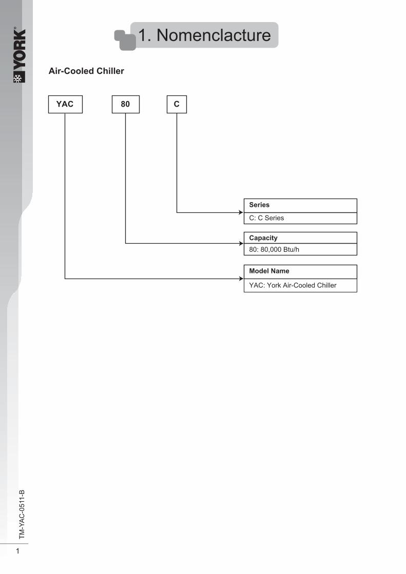
1. Nomenclacture
Air-Cooled Chiller
80YAC
Series
C: C Series
Model Name
YAC: York Air-Cooled Chiller
C
Capacity80: 80,000 Btu/h

®
2
TM-Y
AC
-051
1-B
2. Features
Refrigerant Circuit Models YAC80~150C has been designed with two separate refrigerant circuits, i.e. it has two compressors. By doing so, the unit has part loading capabilities, i.e. 0-50-100% of rated capacity. This will improvethereliabilityandenergyefficiencyof theunit,especiallyduring low loadingoperations.Each circuit is factory brazed and evacuated before accurately charged with refrigerant to ensure optimum performance. Because each circuit is separated, there is no danger of cross-contamination should either one of the compressor experiences a burnt-up. Each circuit is also equipped with a carefully sized thermostatic expansion valve (for cooling only units) to give optimum performance characteristic.
Scroll Compressor Scroll Compressors are used for the units (e.g. YAC20C) which use rotary compressor to give quiet and reliable performance over a wide operating temperature range. However, in order to protect the compressors from damage, a phase protector (which is available in certain models) is provided to prevent the compressors from rotating in the wrong directions. Condenser Fan Motor ModelsYAC80~150Cisequippedwithtwohighairflowpropellerfanbladeswhicharemadeofmetal.The fans are driven vertically by weather proof motors which are single phase type. Evaporator The heat exchanger is made of stainless steel plates closely arranged and brazed together (BPHE) toensurehighheatexchangeefficiency.FormodelsYAC80~150C,thewaterflowthroughtheBPHEinachannelonitsown,whilebecauseofthetwocompressors,therefrigerantflowsthroughanother two separate channels. Safety Protection The safety protections provided for the mini chiller are: a) High and low pressure switches b)Differentialwaterflowswitch c) Compressor, water pump and fan motor overload protectors d) Anti-freeze protection sensor During abnormal condition, chiller panel controller will turn off the unit and then display the faults of operation.
Water Tank And Piping ConnectionThe models YAC80~150C does not come with a water buffer tank. However, the unit does come with an 8 liters expansion tank. Besides that, an optional 135L hydraulic tank is also available.The external water piping connection can be made either from the left or right side of the unit. Connection is done with Ø1-1/4 “ female thread couplings for both supply and return pipes.Meanwhile,YAC20~60Cdoescomewitha22Lor40L(refertospecification)waterbuffertank. Antifreeze Protection The BPHE (Brazed plate heat exchanger) has a strip heater around it to prevent water freezing inside Maintenance In order to facilitate of the controller, a rocker switch is provided to power-off the supply to the PCB. However, switching off the switch will not disconnect the main incoming power supply to the chiller unit.

®
3
TM-Y
AC
-051
1-B
3.Specifications
YAC 20C YAC 25CBtu/h 18,000 23,500
W 5,274 6,886W 2,669 2,730A 12.6 12.6
V/Ph/Hz
ROTARY SCROLL
cm3/fl.oz. 1130 / 38 1240 / 42E NA
V/Ph/Hz 220 - 240 / 1 / 50 220 - 240 / 1 / 50W 2,359 2,405A 11.2 11.1A 67 82µF 45 50
l/s / CFM 1038 / 2200 1038 / 2200R / MIN 910 920
1 1
mm/in
1 1
F FV/Ph/Hz 220 - 240 / 1 / 50 220 - 240 / 1 / 50
W 135 135A 0.67 0.67W 145 145
mm/inmm/in
mm/inm2/ft2 0.66 / 7.1 0.65 / 7.0
1 220 16
0.25 / 0.9 0.33 / 1.2in 1 1
kPa 1000 1000dBA 57 57
MAX. WATER OPER. PRESSURE kPa / psiWATER FLOW RATE l/s / m3/hr 0.25 / 0.9 0.33 / 1.2
F FV/Ph/Hz 220 - 240 / 1 / 50 220 - 240 / 1 / 50
W 175 190A 0.77 0.83
INSTALLATION PIPE CONNECTION mm/inm 9.2 9.5
116 / 256
1.1 / 2.4
123 / 272
1.8 / 4.0
L/ft3
mm/inmm/inmm/in
ALUMINUM0.11 / 0.0043
BRAZED PLATE HEAT EXCHANGER (BPHE)STAINLESS STEEL
SEAMLESS COPPER9.52 / 3/8
0.35 / 0.014
RATED RUNNING CURRENTMOTOR OUTPUT
TYPE
OIL TYPE
CAPACITOR
457.2 / 18
STEEL PLATE
MINERAL OIL
RATED INPUT POWERPOWER SOURCE
EVAPORATOR
AIR FLOW (HIGH)FAN SPEED
LOCKED ROTOR AMP.
PIPING
TANK
HEADMATERIALCAPACITY / VOLUME
INSULATION GRADEPOWER SOURCERATED INPUT POWERRATED RUNNING CURRENT
UNITDIMENSION
PACKINGDIMENSION
HEIGHTWIDTHDEPTH
RUNNING CURRENT, 1Φ [3Φ]POWER SOURCE
INSULATION GRADEPOWER SOURCEFAN MOTOR
TYPEQUANTITY
MATERIALDRIVEDIAMETER
MODEL OUTDOOR UNIT
TOTAL COOLING CAPACITY
INPUT POWER
HYDRAULICKIT
WEIGHT
CASING
REFRIGERANT
CAPILLARY TUBE
CONDENSER (COIL)
SOUND PRESSURE LEVEL (H/M/L)
THICKNESS
INSULATION GRADE
FANTYPEQUANTITY
COMPRESSOR
22 / 0.78
0 - 100%STAGE OF CAPACITY CONTROL (Btu/h)
RATED INPUT POWER
OIL AMOUNT
TYPE
RATED RUNNING CURRENT
TUBEMATERIALDIAMETER
MILD STEEL COATED WITH ZING
ELECTRO-GALVANIZED MILD STEELPOLYESTER POWDER
LIGHT GREY
HIGH HEAD CIRCULATOR
1000 / 145
25.4 / 1
NOMINAL WATER FLOW
DIRECT
PROPELLER
TYPE
INDEX OF PROTECTION (IP)
ROWFIN PER INCH
PUMP
INDUCTION
CROSS FINNED TUBES
800 / 31.51160 / 45.7460 / 18.1958 / 37.7
1309 / 51.5574 / 22.6
220 - 240 / 1 / 50TYPEFLOW CONTROLREFRIGERANT R-22
CAST IRON & STAINLESS STEELMATERIAL
NA
WATER CONNECTIONS (BSP)MAXIMUM WATER PRESSURE
MATERIALTYPE
FIN
MATERIALTHICKNESSFACE AREA
mm/inmm/inmm/inkg/Ib
kg/Ib
HEIGHTWIDTHDEPTH
MATERIALFINISHCOLOUR
OUTDOOR UNIT (R-22)
l/s / m3/hr

®
4
TM-Y
AC
-051
1-B
OUTDOOR UNIT (R-22) YAC 30C YAC 40C
Btu/hWWA
V/Ph/Hz
cm3/fl.oz.
V/Ph/HzWAAµF
l/s / CFMR / MIN
mm/in
V/Ph/HzWAW
mm/inmm/in
mm/inm2/ft2
inkPadBA
MAX. WATER OPER. PRESSURE kPa / psiWATER FLOW RATE l/s / m3/hr
V/Ph/HzWA
INSTALLATION PIPE CONNECTION mm/inm
L/ft3
mm/inmm/inmm/in
RATED RUNNING CURRENTMOTOR OUTPUT
TYPE
OIL TYPE
CAPACITOR
RATED INPUT POWERPOWER SOURCE
EVAPORATOR
AIR FLOW (HIGH)FAN SPEED
LOCKED ROTOR AMP.
PIPING
TANK
HEADMATERIALCAPACITY / VOLUME
INSULATION GRADEPOWER SOURCERATED INPUT POWERRATED RUNNING CURRENT
UNITDIMENSION
PACKINGDIMENSION
HEIGHTWIDTHDEPTH
RUNNING CURRENT, 1Φ [3Φ]POWER SOURCE
INSULATION GRADEPOWER SOURCEFAN MOTOR
TYPEQUANTITY
MATERIALDRIVEDIAMETER
MODEL OUTDOOR UNIT
TOTAL COOLING CAPACITY
INPUT POWER
HYDRAULICKIT
WEIGHT
CASING
REFRIGERANT
CONDENSER (COIL)
SOUND PRESSURE LEVEL (H/M/L)
THICKNESS
INSULATION GRADE
FANTYPEQUANTITY
COMPRESSOR
STAGE OF CAPACITY CONTROL (Btu/h)
RATED INPUT POWER
OIL AMOUNT
TYPE
RATED RUNNING CURRENT
TUBEMATERIALDIAMETER
NOMINAL WATER FLOW
TYPE
INDEX OF PROTECTION (IP)
ROWFIN PER INCH
PUMP
TYPEFLOW CONTROLREFRIGERANT
MATERIAL
WATER CONNECTIONS (BSP)MAXIMUM WATER PRESSURE
MATERIALTYPE
FIN
MATERIALTHICKNESSFACE AREA
mm/inmm/inmm/inkg/Ib
kg/Ib
HEIGHTWIDTHDEPTH
MATERIALFINISHCOLOUR
l/s / m3/hr
27,500 40,0008,058 11,7203,491 4,47016.6 [8.8]
380-415 / 3 / 50
SCROLL SCROLL
1240 / 42 1950 / 66NA NA
220 - 240 / 1 / 50 380 - 415 / 3 / 503,155 3,88015.0 7.6114 6660 NA
1038 / 2200 1038 / 2200920 920
1 2
1 2
F F220 - 240 / 1 / 50 220 - 240 / 1 / 50
135 2700.67 1.34145 145x2
0.65 / 7.0 1.17 / 12.62 216 16
0.39 / 1.4 0.56 / 2.01 1
1000 100058 60
HIGH HEAD CIRCULATOR HORIZONTAL MULTISTAGE END-SUCTION
0.39 / 1.4 0.56 / 2.0F F
220 - 240 / 1 / 50 380 - 415 / 3 / 50201 3200.88 0.71
9.6 9.7
22 / 0.78 40 / 1.41800 / 31.5 1410 / 55.51160 / 45.7 1160 / 45.7
220 - 240 / 1 / 50R-22
0.11 / 0.0043
BRAZED PLATE HEAT EXCHANGER (BPHE)STAINLESS STEEL
CAST IRON & STAINLESS STEEL
PROPELLER
DIRECT
1000 / 145
25.4 / 1
STEEL PLATE
457.2 / 18INDUCTION
NA
CROSS FINNED TUBES
CAPILLARY TUBE
MILD STEEL COATED WITH ZING
0 - 100%MINERAL OIL
SEAMLESS COPPER9.52 / 3/8
0.35 / 0.014ALUMINUM
460 / 18.1 460 / 18.1958 / 37.7 1578 / 62.1
1309 / 51.5 1309 / 51.5574 / 22.6 574 / 22.6128 / 282 195 / 430
1.6 / 3.5 2.7 / 6.0LIGHT GREY
ELECTRO-GALVANIZED MILD STEELPOLYESTER POWDER

®
5
TM-Y
AC
-051
1-B
OUTDOOR UNIT (R-22)
Btu/hWWA
V/Ph/Hz
cm3/fl.oz.
V/Ph/HzWAAµF
l/s / CFMR / MIN
mm/in
V/Ph/HzWAW
mm/inmm/in
mm/inm2/ft2
inkPadBA
MAX. WATER OPER. PRESSURE kPa / psiWATER FLOW RATE l/s / m3/hr
V/Ph/HzWA
INSTALLATION PIPE CONNECTION mm/inm
L/ft3
mm/inmm/inmm/in
RATED RUNNING CURRENTMOTOR OUTPUT
TYPE
OIL TYPE
CAPACITOR
RATED INPUT POWERPOWER SOURCE
EVAPORATOR
AIR FLOW (HIGH)FAN SPEED
LOCKED ROTOR AMP.
PIPING
TANK
HEADMATERIALCAPACITY / VOLUME
INSULATION GRADEPOWER SOURCERATED INPUT POWERRATED RUNNING CURRENT
UNITDIMENSION
PACKINGDIMENSION
HEIGHTWIDTHDEPTH
RUNNING CURRENT, 1Φ [3Φ]POWER SOURCE
INSULATION GRADEPOWER SOURCEFAN MOTOR
TYPEQUANTITY
MATERIALDRIVEDIAMETER
MODEL OUTDOOR UNIT
TOTAL COOLING CAPACITY
INPUT POWER
HYDRAULICKIT
WEIGHT
CASING
REFRIGERANT
CONDENSER (COIL)
SOUND PRESSURE LEVEL (H/M/L)
THICKNESS
INSULATION GRADE
FANTYPEQUANTITY
COMPRESSOR
STAGE OF CAPACITY CONTROL (Btu/h)
RATED INPUT POWER
OIL AMOUNT
TYPE
RATED RUNNING CURRENT
TUBEMATERIALDIAMETER
NOMINAL WATER FLOW
TYPE
INDEX OF PROTECTION (IP)
ROWFIN PER INCH
PUMP
TYPEFLOW CONTROLREFRIGERANT
MATERIAL
WATER CONNECTIONS (BSP)MAXIMUM WATER PRESSURE
MATERIALTYPE
FIN
MATERIALTHICKNESSFACE AREA
mm/inmm/inmm/inkg/Ib
kg/Ib
HEIGHTWIDTHDEPTH
MATERIALFINISHCOLOUR
l/s / m3/hr
YAC 50C YAC 60C50,000 53,00014,650 15,5295,245 6,361[9.3] [12.3]
1770 / 60 1770 / 60NA NA
380 - 415 / 3 / 50 380 - 415 / 3 / 504,630 4,6308.1 11.174 101NA NA
1038 / 2200 1038 / 2200920 920
2 2
2 2
F F220 - 240 / 1 / 50 220 - 240 / 1 / 50
270 2701.34 1.34
145x2 145x2
0.35 / 0.014 0.33 / 0.013
1.17 / 12.6 1.17 / 12.62 2
16 16
0.70 / 2.5 0.74 / 2.71 1
1000 100060 61
0.70 / 2.5 0.74 / 2.7F F
380 - 415 / 3 / 50 380 - 415 / 3 / 50345 3510.77 0.78
7.5 8.3
196 / 432 203 / 448
3.1 / 6.8 3.1 / 6.8LIGHT GREY
ELECTRO-GALVANIZED MILD STEELPOLYESTER POWDER
1578 / 62.11309 / 51.5574 / 22.6
1410 / 55.51160 / 45.7460 / 18.1
25.4 / 1
MILD STEEL COATED WITH ZING40 / 1.41
HORIZONTAL MULTISTAGE END-SUCTIONCAST IRON & STAINLESS STEEL
1000 / 145
STAINLESS STEEL
ALUMINUM0.11 / 0.0043
CROSS FINNED TUBESSEAMLESS COPPER
9.52 / 3/8
457.2 / 18INDUCTION
CAPILLARY TUBE
380-415 / 3 / 50R-22
SCROLL
NA
0 - 100%MINERAL OIL
PROPELLER
STEEL PLATEDIRECT
BRAZED PLATE HEAT EXCHANGER (BPHE)

®
6
TM-Y
AC
-051
1-B
OUTDOOR UNIT (R-22)
Btu/hWWA
V/Ph/Hz
cm3/fl.oz.
V/Ph/HzWAAµF
l/s / CFMR / MIN
mm/in
V/Ph/HzWAW
mm/inmm/in
mm/inm2/ft2
inkPadBA
MAX. WATER OPER. PRESSURE kPa / psiWATER FLOW RATE l/s / m3/hr
V/Ph/HzWA
INSTALLATION PIPE CONNECTION mm/inm
L/ft3
mm/inmm/inmm/in
RATED RUNNING CURRENTMOTOR OUTPUT
TYPE
OIL TYPE
CAPACITOR
RATED INPUT POWERPOWER SOURCE
EVAPORATOR
AIR FLOW (HIGH)FAN SPEED
LOCKED ROTOR AMP.
PIPING
TANK
HEADMATERIALCAPACITY / VOLUME
INSULATION GRADEPOWER SOURCERATED INPUT POWERRATED RUNNING CURRENT
UNITDIMENSION
PACKINGDIMENSION
HEIGHTWIDTHDEPTH
RUNNING CURRENT, 1Φ [3Φ]POWER SOURCE
INSULATION GRADEPOWER SOURCEFAN MOTOR
TYPEQUANTITY
MATERIALDRIVEDIAMETER
MODEL OUTDOOR UNIT
TOTAL COOLING CAPACITY
INPUT POWER
HYDRAULICKIT
WEIGHT
CASING
REFRIGERANT
CONDENSER (COIL)
SOUND PRESSURE LEVEL (H/M/L)
THICKNESS
INSULATION GRADE
FANTYPEQUANTITY
COMPRESSOR
STAGE OF CAPACITY CONTROL (Btu/h)
RATED INPUT POWER
OIL AMOUNT
TYPE
RATED RUNNING CURRENT
TUBEMATERIALDIAMETER
NOMINAL WATER FLOW
TYPE
INDEX OF PROTECTION (IP)
ROWFIN PER INCH
PUMP
TYPEFLOW CONTROL
COMPRESSOR 1COMPRESSOR 2
REFRIGERANT
MATERIAL
WATER CONNECTIONS (BSP)MAXIMUM WATER PRESSURE
MATERIALTYPE
FIN
MATERIALTHICKNESSFACE AREA
mm/inmm/inmm/inkg/Ib
kg/Ib
HEIGHTWIDTHDEPTH
MATERIALFINISHCOLOUR
l/s / m3/hr
YAC 80C YAC 100C78,000 93,00022,854 27,2498,667 10,175[16.3] [17.0]
1950 / 66 1770 / 601950 / 66 1770 / 60
NA NA380 - 415 / 3 / 50 380 - 415 / 3 / 50
7,052 8,56014.0 14.7
66 / 66 74 / 74NA NA
1800 / 3814 1800 / 3814690 690
2 2
2 2
F F220 - 240 / 1 / 50 220 - 240 / 1 / 50
565 5652.4 2.4
120x2 120x2
1.37 / 14.7 1.37 / 14.72 214 14
1.08 / 3.9 1.31 / 4.71¼ 1¼
1000 100065 66
1.08 / 3.9 1.31 / 4.7F F
380 - 415 / 3 / 50 380 - 415 / 3 / 501050 10501.5 1.5
42 / 1¼ 42 / 1¼21.6 18.7
340 / 750 350 / 772
4.5x2 / 9.9x2 3.9x2 / 8.6x2
SCROLL0 - 50 - 100%MINERAL OIL
DIRECT609.6 / 24
CAST IRON & STAINLESS STEEL1000 / 145
NA
CROSS FINNED TUBES
STAINLESS STEEL
ELECTRO-GALVANIZED MILD STEELPOLYESTER POWDER
LIGHT GREY
1032 / 40.6
NA1245 / 49.01500 / 59.1900 / 35.4
1452 / 57.21732 / 68.2
HORIZONTAL MULTISTAGE END-SUCTION
380-415 / 3 / 50R-22
INDUCTION
NA
PROPELLER
ALUMINIUM
TXV
SEAMLESS COPPER9.52 / ⅜
ALUMINUM (HYDROPHILIC)0.11 / 0.0043
0.33 / 0.013
BRAZED PLATE HEAT EXCHANGER (BPHE)

®
7
TM-Y
AC
-051
1-B
OUTDOOR UNIT (R-22)
Btu/hWWA
V/Ph/Hz
cm3/fl.oz.
V/Ph/HzWAAµF
l/s / CFMR / MIN
mm/in
V/Ph/HzWAW
mm/inmm/in
mm/inm2/ft2
inkPadBA
MAX. WATER OPER. PRESSURE kPa / psiWATER FLOW RATE l/s / m3/hr
V/Ph/HzWA
INSTALLATION PIPE CONNECTION mm/inm
L/ft3
mm/inmm/inmm/in
RATED RUNNING CURRENTMOTOR OUTPUT
TYPE
OIL TYPE
CAPACITOR
RATED INPUT POWERPOWER SOURCE
EVAPORATOR
AIR FLOW (HIGH)FAN SPEED
LOCKED ROTOR AMP.
PIPING
TANK
HEADMATERIALCAPACITY / VOLUME
INSULATION GRADEPOWER SOURCERATED INPUT POWERRATED RUNNING CURRENT
UNITDIMENSION
PACKINGDIMENSION
HEIGHTWIDTHDEPTH
RUNNING CURRENT, 1Φ [3Φ]POWER SOURCE
INSULATION GRADEPOWER SOURCEFAN MOTOR
TYPEQUANTITY
MATERIALDRIVEDIAMETER
MODEL OUTDOOR UNIT
TOTAL COOLING CAPACITY
INPUT POWER
HYDRAULICKIT
WEIGHT
CASING
REFRIGERANT
CONDENSER (COIL)
SOUND PRESSURE LEVEL (H/M/L)
THICKNESS
INSULATION GRADE
FANTYPEQUANTITY
COMPRESSOR
STAGE OF CAPACITY CONTROL (Btu/h)
RATED INPUT POWER
OIL AMOUNT
TYPE
RATED RUNNING CURRENT
TUBEMATERIALDIAMETER
NOMINAL WATER FLOW
TYPE
INDEX OF PROTECTION (IP)
ROWFIN PER INCH
PUMP
TYPEFLOW CONTROLREFRIGERANT
MATERIAL
WATER CONNECTIONS (BSP)MAXIMUM WATER PRESSURE
MATERIALTYPE
FIN
MATERIALTHICKNESSFACE AREA
mm/inmm/inmm/inkg/Ib
kg/Ib
HEIGHTWIDTHDEPTH
MATERIALFINISHCOLOUR
l/s / m3/hr
YAC 120C YAC 150C116,000 138,00033,988 40,43411,005 13,779[22.9] [26.7]
1770 / 60 2510 / 851770 / 60 2510 / 85
NA NA380 - 415 / 3 / 50 380 - 415 / 3 / 50
9,433 11,44719.7 22.4
101 / 101 95 / 95NA NA
4000 / 8476 4000 / 8476650 780
2 2
2 2
F F220 - 240 / 1 / 50 220 - 240 / 1 / 50
772 1,5323.6 6.8
200x2 450x2
1.79 / 19.3 1.79 / 19.32 2
14 14
1.67 / 6.0 2.00 / 7.21¼ 1¼
1000 100067 69
1.67 / 6.0 2.00 / 7.2F F
380 - 415 / 3 / 50 380 - 415 / 3 / 50800 8002 2
42 / 1¼ 42 / 1¼19.2 16.5
460 / 1014 540 / 1190
6.0x2 / 13.2x2 7.1x2 / 15.7x2
SCROLL0 - 50 - 100%
DIRECT
1000 / 145
NA
2032 / 80.0
CAST IRON & STAINLESS STEEL
1452 / 57.2
HORIZONTAL MULTISTAGE END-SUCTION
STAINLESS STEEL
380-415 / 3 / 50R-22
PROPELLER
0.33 / 0.013ALUMINUM (HYDROPHILIC)
0.11 / 0.0043
BRAZED PLATE HEAT EXCHANGER (BPHE)
MINERAL OIL
CROSS FINNED TUBESSEAMLESS COPPER
9.52 / ⅜
ALUMINIUM
609.6 / 24INDUCTION
NA
TXV
NA1245 / 49.01800 / 70.91150 / 45.3
ELECTRO-GALVANIZED MILD STEELPOLYESTER POWDER
LIGHT GREY
1282 / 50.5
COMPRESSOR 1COMPRESSOR 2

®
8
TM-Y
AC
-051
1-B
Safety Devices - R-22 Cooling only
1) ALL SPECIFICATIONS ARE SUBJECTED TO CHANGE BY THE MANUFACTURER WITHOUT PRIOR NOTICE.
YAC 20C YAC 25C
NC NC
OPEN kPa / psi 2939 / 426 2939 / 426
CLOSE kPa / psi 2415 / 350 2415 / 350
NC NC
OPEN kPa / psi 124 / 18 125 / 18
CLOSE kPa / psi 193 / 28 193 / 28
DIFFERENTIAL PRESSURE SWITCH YES YES
ANTI-FREEZE PROTECTION SENSOR YES YES
OVER PRESSURE RELIEF VALVE YES YES
YES YES
YES YES
MODEL
COMPRESSOR OLP
HIGH PRESSURE SWITCH
LOW PRESSURE SWITCH
PUMP OLP
TYPE
TYPE
SAFETY DEVICE
YAC 30C YAC 40C
NC NC
OPEN kPa / psi 2939 / 426 2939 / 426
CLOSE kPa / psi 2415 / 350 2415 / 350
NC NC
OPEN kPa / psi 124 / 18 125 / 18
CLOSE kPa / psi 193 / 28 193 / 28
BUILT IN ON BOARD
DIFFERENTIAL PRESSURE SWITCH
PHASE PROTECTION
YES
NA
NA
YES
ANTI-FREEZE PROTECTION SENSOR
DISCH.THERMOSTAT SETTING
YES YES
110 / 230
OVER PRESSURE RELIEF VALVE YES YES
YES YES
YES YES
MODEL
COMPRESSOR OLP
HIGH PRESSURE SWITCH
LOW PRESSURE SWITCH
PUMP OLP
TYPE
TYPE
SAFETY DEVICE
YAC 50C YAC 60C
NC NC
OPEN kPa / psi 2939 / 426 2939 / 426
CLOSE kPa / psi 2415 / 350 2415 / 350
NC NC
OPEN kPa / psi 124 / 18 125 / 18
CLOSE kPa / psi 193 / 28 193 / 28
BUILT IN ON BOARD
DIFFERENTIAL PRESSURE SWITCH
PHASE PROTECTION
YES
BUILT IN ON BOARD
110 / 230
YES
ANTI-FREEZE PROTECTION SENSOR
DISCH.THERMOSTAT SETTING
YES YES
110 / 230
OVER PRESSURE RELIEF VALVE YES YES
YES YES
YES YES
MODEL
COMPRESSOR OLP
HIGH PRESSURE SWITCH
LOW PRESSURE SWITCH
PUMP OLP
TYPE
TYPE
SAFETY DEVICE
˚C/˚F
˚C/˚F

®
9
TM-Y
AC
-051
1-B
Safety Devices - R-22 Cooling only
1) ALL SPECIFICATIONS ARE SUBJECTED TO CHANGE BY THE MANUFACTURER WITHOUT PRIOR NOTICE.
YAC 80C YAC 100C
NC NC
OPEN kPa / psi 2939 / 426 2939 / 426
CLOSE kPa / psi 2415 / 350 2415 / 350
NC NC
OPEN kPa / psi 124 / 18 125 / 18
CLOSE kPa / psi 193 / 28 193 / 28
BUILT IN ON BOARD
DIFFERENTIAL PRESSURE SWITCH
PHASE PROTECTION
YES
BUILT IN ON BOARD
110 / 230
YES
ANTI-FREEZE PROTECTION SENSOR
DISCH.THERMOSTAT SETTING
YES YES
110 / 230
OVER PRESSURE RELIEF VALVE YES YES
YES YES
YES YES
MODEL
COMPRESSOR OLP
HIGH PRESSURE SWITCH
LOW PRESSURE SWITCH
PUMP OLP
TYPE
TYPE
SAFETY DEVICE
YAC 120C YAC 150C
NC NC
OPEN kPa / psi 2939 / 426 2939 / 426
CLOSE kPa / psi 2415 / 350 2415 / 350
NC NC
OPEN kPa / psi 124 / 18 125 / 18
CLOSE kPa / psi 193 / 28 193 / 28
BUILT IN ON BOARD
DIFFERENTIAL PRESSURE SWITCH
PHASE PROTECTION
YES
BUILT IN ON BOARD
110 / 230
YES
ANTI-FREEZE PROTECTION SENSOR
DISCH.THERMOSTAT SETTING
YES YES
110 / 230
OVER PRESSURE RELIEF VALVE YES YES
YES YES
YES YES
MODEL
COMPRESSOR OLP
HIGH PRESSURE SWITCH
LOW PRESSURE SWITCH
PUMP OLP
TYPE
TYPE
SAFETY DEVICE
˚C/˚F
˚C/˚F

®
10
TM-Y
AC
-051
1-B
4. Selection Process
Water Pressure Drop vs Flow Rate
Water Flow m3/hr
Pump Head kPa Available Head Pressure kPa
0.6 117.0 12.0 105.00.8 115.0 25.0 90.01.0 114.0 34.0 80.01.2 112.0 50.0 62.01.4 108.0 59.9 48.1
Water Flow m3/hr
Pump Head kPa Available Head Pressure kPa
0.7 116.0 10.4 105.60.8 116.0 10.8 105.21.0 114.0 15.2 98.81.3 110.0 20.9 89.11.5 105.0 27.9 77.11.8 100.0 35.2 64.8
Water Flow m3/hr
Pump Head kPa Available Head PressurekPa
0.9 115.0 7.4 107.61.2 112.0 12.3 99.71.5 105.0 19.6 85.41.8 98.0 29.4 68.62.1 90.0 36.8 53.2
Water Flow m3/hr
Pump Head kPa Available Head Pressure kPa
1.2 168.0 26.3 141.71.6 162.0 26.5 135.52.0 144.0 34.3 109.72.4 137.0 49.5 87.52.8 113.0 62.5 50.5
Water Flow m3/hr
Pump Head kPa System Head kPa Available Head Pressure kPa
1.5 163.0 15.0 148.02.0 144.0 25.7 118.32.5 126.0 39.4 86.63.0 107.0 52.6 54.4
Model: YAC 20C
Model: YAC 25C
Model: YAC 30C
Model: YAC 40C
Model: YAC 50C
System Head kPa
System Head kPa
System Head kPa
System Head kPa

®
11
TM-Y
AC
-051
1-B
Water Flow m3/hr
Pump Head kPa Available Head Pressure kPa
1.8 150.0 10.5 139.52.4 137.0 22.8 114.23.0 107.0 39.0 68.03.2 69.0 41.8 27.2
Water Flow m3/hr
Pump Head kPa Available Head Pressure kPa
2.4 300.0 18.7 281.33.2 270.0 32.6 237.44.0 260.0 49.3 210.74.8 230.0 69.6 160.45.6 200.0 93.5 106.56.4 175.0 121.0 54.0
Water Flow m3/hr
Pump Head kPa Available Head Pressure kPa
3.0 280.0 22.9 257.14.0 260.0 39.3 220.75.0 220.0 59.8 160.26.0 180.0 84.2 95.87.0 150.0 112.6 37.4
Water Flow m3/hr
Pump Head kPa Available Head Pressure kPa
3.0 280.0 16.6 263.44.0 270.0 28.6 241.45.0 260.0 43.6 216.46.0 250.0 61.5 188.57.0 230.0 82.4 147.6
Water Flow m3/hr
Pump Head kPa Available Head Pressure kPa
3.0 280.0 13.8 266.24.0 270.0 23.7 246.35.0 260.0 36.0 224.06.0 250.0 50.7 199.37.0 230.0 67.8 162.28.0 210.0 87.1 122.9
Model: YAC 60C
Model: YAC 80C
Model: YAC 100C
Model: YAC 120C
Model: YAC 150C
System Head kPa
System Head kPa
System Head kPa
System Head kPa
System Head kPa

®
12
TM-Y
AC
-051
1-B
5. Application Information
Model: YAC 20/25/30C
Model: YAC 40/50/60C
P
FILTERILILDRIER CAP TUBE
BPHE
COMPRESSOR
WATER PUMPAA
AUTO PRESS RELIEF VA V V LVLL E
WATERAAOUT
WATERAAIN
EXPANSIONPPTANKTT
WATER STAA ORAGE TANK T T
P
FILTERILILDRIER CAP TUBE
BPHE
COMPRESSOR
WATER PUMPAA
AUTO PRESS RELIEF VALVE
WATEROUT
WAATERIN
EXPANSIONTANKT
WATER STAA
ORAGE TANK T T
Refrigerant Circuit Diagram
®
13
TM-Y
AC
-051
1-B
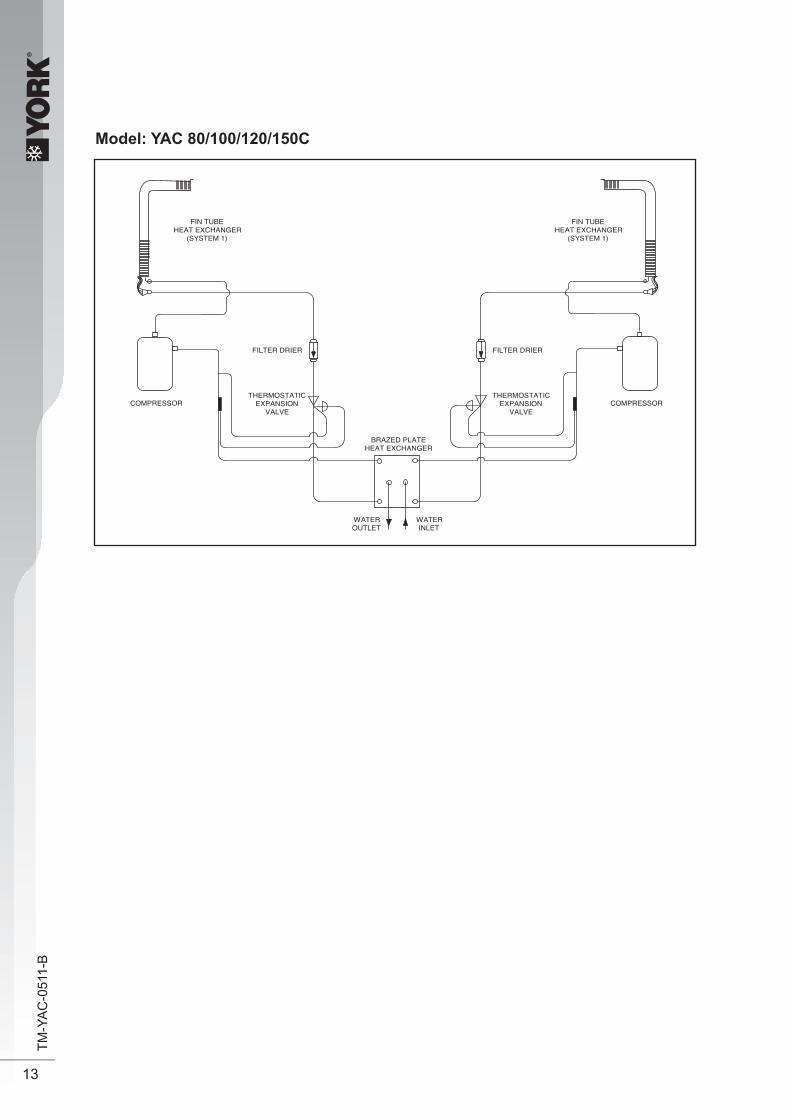
Model: YAC 80/100/120/150C
FIN TUBEHEAT EXCHANGER
(SYSTEM 1)
FIN TUBEHEAT EXCHANGER
(SYSTEM 1)
COMPRESSOR COMPRESSOR
FILTER DRIER FILTER DRIER
WATEROUTLET
WATERINLET
THERMOSTATICEXPANSION
VALVE
THERMOSTATICEXPANSION
VALVE
BRAZED PLATEHEAT EXCHANGER

®
14
TM-Y
AC
-051
1-B
Chiller Panel Controller
1. Safety Consideration Only specially trained and technicians and installers are authorized to install and service this
equipment.
1.1 General Installation Recommendations • OnlysupplyDCvoltage(9-17V,typically12V,maximumcurrent200mA)asapowersourceto
the device. • Inputcontactvoltagesupplyshouldlimitto12VDCor24VAC. • Isolatedallthelowvoltagewiring(communicationbus,etc)fromhighvoltagepowersupply
wiring.
2. General Description
2.1 General The chiller panel controller is designed to control the chiller operation. This device allows the
user to have customized control for each connected unit.
2.2 Features The requirements of user friendly and easy to use have been taken into account in designing
this chiller panel controller. It can do the task as follow: • Wholesystemconfiguration • Uniqueparametersettings • Operationstatusdisplay • Tracingfaultrecord(easyinhardwaretroubleshooting) The display is shown in an 8-lines graphical LCD display. There are 8 dedicated keys available
in the panel, • Menuselection • Navigationonthescreen • Modificationoftheselectedvalue During first start-up, the panel will have a default configuration (timer schedule, set point,
miscellaneoussettings,etc)Usercandothechangesonthatparticularconfigurationlater.
2.3 Panel Position The chiller panel controller can be installed anywhere, as long as it is easy to accessed by
authorized personnel. The requirements of installation are: • Avoidexposuretoshocks • Avoidanysourceofelectromagneticpollution • Avoidinstallationonunevenverticalsurface
2.4 Operation Environmental Condition • Temperature: - 10°C to 65°C operating temperature - 20°C to 85°C storage temperature
• Relative Humidity: 0 to 95% non-condensing

®
15
TM-Y
AC
-051
1-B
3. Hardware Description
1 & 2 Navigation key3 Execute instruction key4 Cancel instruction key6 Switching to cool mode shortcut key7 Toggle ON/OFF shortcut key8 Show alarm key9 Graphical LCD display10 ON/OFF indicator
Legend
1 & 2 Chiller terminal unit connectionLegend
3.1 Key Explanation
The 2 navigation keys permit item selection and modifying the selected value.
ENTER key is used to execute the navigation instruction
ESC key is used to cancel the navigation instruction
Shortcut key to switch the operation mode in the summary pages
Shortcut key to trigger ON/OFF in the summary pages
Shortcut key to show fault / alarm in the summary pages
3 Not available4 CMOS rset jumper (JH2)5 Chiller bus resist or configuration (JH3)6 Not available7 Not available8 Not available9 Not available10 Backup battery
ENTER
ESC
ON/OFF
ALARM
COOL

®
16
TM-Y
AC
-051
1-B
4. Installation
4.1 Chiller Bus
Chiller panel needs to be energized with +12Vdc. The 5 way wires that provided is once on the easiest solution to establish a communication between the panel and chiller main board (CN8-CN8). If the 5-way wires socket has been occupied in main board, just using 2 insulation wired are needed to establish a communication between panel and chiller main board.
Chiller panel can support maximum up to 50 units of chiller. In the chiller network, duplication of main board unit address is not allowed. Each chiller main board should have their unique unit address (0-50).Forfirsttimerunning,userneedtoassignauniqueunitaddresstoeachmainboardinthechillernetwork.Usershouldfollowtheprocedurebelow:
• Only power ON one main board at once time. Make sure not others main boards are energize.• By using the panel connected to the main board.
• Key in unique unit address and press ENTER to execute.• De-energized the main board and repeat the procedures again all the main boards have been
assigned a unique unit address.
IMPORTANT : Do not assign a same unit address to more than one chiller main board.
RECOMMENDATION : Please select a coherant model (G1 Model) to all the chiller main boards in the same network.
Supported up to 50 units of Chiller
Chiller 0 Chiller 1 Chiller 25 way wire (CM8)ChillerCommunication bus
Chiller Panel 0 (Master)
Chiller Panel 1(Slave)
Chiller Network
Summary Pages
<ENTER> <ENTER>
<ENTER>key in “0001” as password
<ENTER>G7 Unit No
Main Menu
1. General
Setting Menu
Set Parameter
®
17
TM-Y
AC
-051
1-B
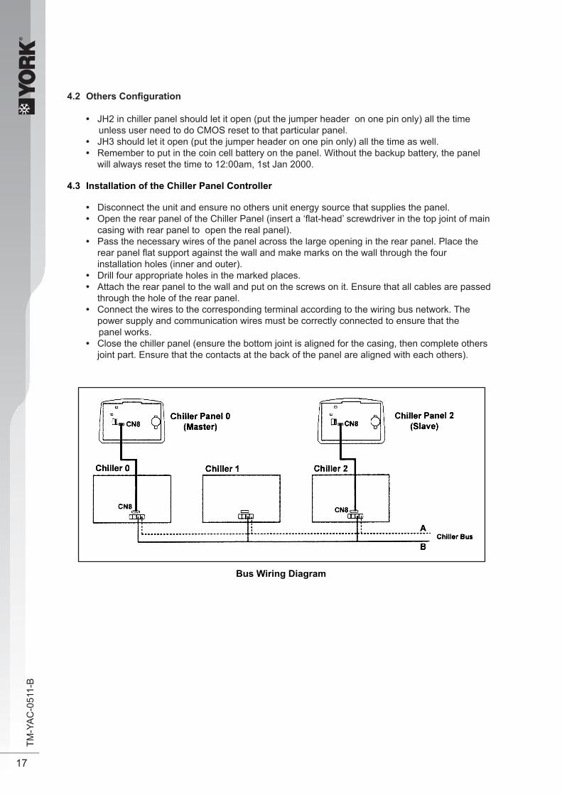
4.2 OthersConfiguration
• JH2 in chiller panel should let it open (put the jumper header on one pin only) all the time unless user need to do CMOS reset to that particular panel. • JH3 should let it open (put the jumper header on one pin only) all the time as well. • Remember to put in the coin cell battery on the panel. Without the backup battery, the panel
will always reset the time to 12:00am, 1st Jan 2000.
4.3 Installation of the Chiller Panel Controller • Disconnect the unit and ensure no others unit energy source that supplies the panel. • OpentherearpaneloftheChillerPanel(inserta‘flat-head’screwdriverinthetopjointofmain
casing with rear panel to open the real panel). • Pass the necessary wires of the panel across the large opening in the rear panel. Place the
rearpanelflatsupportagainstthewallandmakemarksonthewallthroughthefour installation holes (inner and outer).
• Drill four appropriate holes in the marked places. • Attach the rear panel to the wall and put on the screws on it. Ensure that all cables are passed
through the hole of the rear panel. • Connect the wires to the corresponding terminal according to the wiring bus network. The power supply and communication wires must be correctly connected to ensure that the panel works. • Close the chiller panel (ensure the bottom joint is aligned for the casing, then complete others
joint part. Ensure that the contacts at the back of the panel are aligned with each others).
Bus Wiring Diagram

®
18
TM-Y
AC
-051
1-B
5. Software Description
5.1 Introduction The Chiller Panel Controller can be used to control / display the status of Chiller.
Status viewing: •ON/OFF status • Mode set temperature • Compressor status (ON/OFF) •Water in, Water Out, Outdoor air and Panel temperature • Advance parameter settings • Defrost sensor temperatures •Compressor discharge sensor temperatures • Compressor run times • Incoming alarm/ fault/ error
Status settings: •ON/OFF switching • Mode set temperature •Advance parameter settings • Password changing • Panel option setting (Backlight, Alarm Buzzer, Screen saver, Contrast, Brightness, temperature unit) • Time and date settings • Clearing compressor run time

®
19
TM-Y
AC
-051
1-B
Menu Structure Diagram for Chiller
5.2 Menu Structures
Summary Pages
Main Menu
Settings Menu
Timer Menu
Alarm Menu
Display Menu
UnitSelectionMenu
Set Parameter
General
Sensor
Regulator
Compressor
Antifreeze
Alarm and Contact
Clock Setting
Date Setting
Show Alarms
Discharge Sensor
Schedule Timer
Erase All Alarms
Comp Run Time [#] [#] - Password Required
Change Password
Panel Option
Set Panel ID
[#]
[#]

®
20
TM-Y
AC
-051
1-B
5.3 Chiller Menu Structure
5.3.1 Summary Pages There are 4 pages in [Summary Pages]. Press UP or DOWN for page scrolling. Press
ENTER to go to [Main Menu]. Time and date are shown on top of each page. Beside that, the bottom of each page shows current control unit of the Chiller.
For example: [00] - Chiller Panel controls Chiller ID 0 currently [03] - Chiller Panel controls Chiller ID 3 currently [All] - Chiller Panel controls all Chiller currently
1st page: Display ON/OFF status, Mode settings and Temperature settings.
2nd page: Display Compressor status.
3rd page: Display Water In, Water Out, Outdoor air and Panel temperature
4th page: DisplayChiller model, Compressor No. and Chiller ID.
01/01/2000 12:00am
Status : ON
Mode : Cooling
Cool Temp : 12.0°C
[00]
01/01/2000 12:00am
Compressor : ON
[00]
01/01/2000 12:00am
Water In :19.8°CWater Out : 25.6°COutdoor Air : 32.2°CPanel : 20.5°C
[00]
01/01/2000 12:00am
Model : Chiller
No. Comp : 1 Comp
Unit No : 0

®
21
TM-Y
AC
-051
1-B
5.3.2 Main Menu Press ENTER in [Summary Pages] to go into this menu
There are 5 sub menus in [Main Menu]. Press UP or DOWN to select sub menus, ENTER to enter into the sub menu or press ESC to exit to [Summary Pages]
5.3.2.1 Operation Menu Select [Operation Menu] in [Main Menu] and press ENTER to go into this menu.
Some normal settings can be found here. Press UP or DOWN to select each settings, ENTER to start the setting or press ESC here to exit to [Main Menu]
Settings : - ON/OFF unit - Cooling temperature setting
MAIN MENU Operating Menu Setting MenuTimer MenuAlarm MenuDisplay Menu
OPERATION MENU Status : ON Mode : Cooling Cool Temperature : 12.0° C

®
22
TM-Y
AC
-051
1-B
5.3.2.2 Settings Menu Select [Settings Menu] in [Main Menu] and press ENTER to go into this menu.
Some advance settings can be found here. Press UP or DOWN to select settings, ENTER to start the setting or press ESC here to exit to [Main Menu]. Settings: - Set Parameter - Password Changing - Panel Option - Set Panel ID
SETTINGS MENU Set Parameter Change Password Panel Option Set Panel ID
5.3.2.2.1 Panel Option Select [Panel Option] in [Setting Menu] and Press ENTER to go into this menu.
Usercandosomemiscellaneousforthepanel.Thesesettingswouldnotaffectwholesystem performance.
Settings - Toggle Backlight - Alarm Buzzer - Enable / Disable Screen Saver - Screen Saver timeout - Contrast display - Backlight brightness - Temperature unit
Press ESC to exit to [Settings Menu]
5.3.2.2.2 Set Panel ID Select [Set Panel ID] in [Settings Menu] and press ENTER to go into this menu.
UsercanassigntheIDno,tothepanel. Example:IfIDno.0hasbeenassigned,thepanelactslikeMasterPanelUnit.Itcanchoose to control each Chiller in the network.
IfotherIDno.(1-50)hasbeenassigned,thepanelactslikeSlavePanelUnit.Itisdedicatedto one particular Chiller. It can only control the Chiller with same ID in the network.
Press [ESC] to exit to [Settings Menu]
Please enter the Panel ID……
=> Unit 0
Backlight : Normal : Buzzer : OnScreen Saver : Disable Timeout : 5m Contrast : 50% Brightness : Medium Temp Unit : ° C

®
23
TM-Y
AC
-051
1-B
5.3.2.3 Time Menu Select [Time Menu] in [Main Menu] and press ENTER to go into this menu.
All the timer/ schedule settings are included in this menu. Press UP or DOWN to select each settings. ENTER to start the setting or press ESC here to exit to [Main Menu].
Settings: - Set Clock - Set Date - Set Schedule ( 7 days Programmable Timer) - Enable/ Disable Timer Schedule
5.3.2.3.1 Set Clock Select [Clock Setting] in [Timer Menu] and press ENTER to go into this menu.
Usercansetthetimeinthismenu.Thetimesettingisin24-hourformat.
Pres [ESC] to exit to [Timer Menu].
TIMER MENU Clock Setting : Date Setting Time Schedule Timer : Disable
Set Time : hh: mm 00: 00

®
24
TM-Y
AC
-051
1-B
5.3.2.3.2 Set Date Select [Date Setting] in [Timer Menu] and press ENTER to go into this menu.
Usercansetthedateinthismenu.Thedateissetaccordingtosequencebelow:
(year) / (month) / (day)
Press [ESC] to exit to [Timer Menu].
5.3.2.3.3 Set Schedule Select [Schedule Timer] in [Timer Menu] and press ENTER to go into this menu.
This is the 7 days programmable timer schedule menu. There are 2 ON/OFF events in one day.Usercanchoosetoseteachdayofweek(Sunday-Saturday)ON/OFFtimer.Beforethis schedule carry their effect to the Chiller, user need to set the [Timer] in [Timer Menu] to enable.
Press [ESC] to exit to [Timer Menu].
5.3.2.4 Alarm Menu Select [Alarm Menu] in [Main Menu] and press ENTER to go into this menu.
Thisplacekeeps records forallpreviousoccurred fault/alarms.Usercanview thealarm history and clear that record (alarm history) as well. The panel can keep up to 20 fault / alarm records.
Press ESC to exit to [Main Menu]
Set Time :
yyyy hh mm
2000 /01 / 01
Timer 1 Timer2 ON OFF ON OFF
Sun 0800 1600 _ _ _ _ _ _ _ _ Mon 0800 1600 _ _ _ _ _ _ _ _ Tue 0800 1600 _ _ _ _ _ _ _ _ Wed 0800 1600 _ _ _ _ _ _ _ _
ALARM MENU
Show Alarms
Erase All Alarm

®
25
TM-Y
AC
-051
1-B
5.3.2.4.1 Show Alarms Select [Show Alarms] in [Alarm Menu] and press ENTER to go into this menu.
Usercanviewallthefault/alarmrecordsinthismenu.
The record shows: - Alarm type - Alarm occurred date - Alarm occurred time - Alarm occurred unit (Chiller ID)
Beside that, user can erase the alarm record in this menu.
Press [ESC] to exit to [Alarm Menu].
5.3.2.4.2 Erase All Alarms Select [Erase All Alarms] in [Alarm Menu] and press ENTER to go into this menu.
Usercanraseallthealarm/faultrecordsatonceinthismenu.
Press [ESC] to exit to [Alarm Menu].
5.3.2.5 Display Menu Select [Display Menu] in [Main Menu] and press ENTER to go into this menu.
This menu display Compressor Discharge sensor temperature and Compressor Run Time. Beside that, user can clear each Compressor Run Time for Chiller.
Press [ESC] to exit to [Main Menu]
[Ch 0] Alarm 1
Comp 1 overload
01/ 01/ 00 12:00am
Are you sure ?
Press Enter to erase, or ESC to exit.
DISPLAY MENU
Discharge Sensor Comp Run Time

®
26
TM-Y
AC
-051
1-B
5.3.2.5.1 Discharge Sensor Select [Discharge Sensor] in [Display Menu] and press ENTER to go into this menu.
UsercanviewthedischargesensortemperatureforeachcompressorintheChiller.
Press [ESC] to exit to [Display Menu].
6. Operation User Manual
6.1 Starting
ChillerpanelcanbesetasMasterorSlavepanelunit.WhenthePanelIDissetto‘0’,itactslikea Master panel, whereas it is Slave panel if Panel ID is set to others number (1-50).
Chiller panel can control the Chiller if both ID no. (Panel ID and Chiller ID) are same.
For example: Panel ID 1 can only control Chiller ID 1
Master Panel can choose to control each Chiller or control all Chiller at once in the network.
For example : Panel ID 0 (master) can control Chiller ID 0 / ID 1/ ID 32 .... or all Chillers at once.
Panel ID can be set in Set Panel ID in Settings Menu.
Please enter the Panel ID ……
=> Unit 0
Discharge Sensor
Comp1:36.5˚C
®
27
TM-Y
AC
-051
1-B
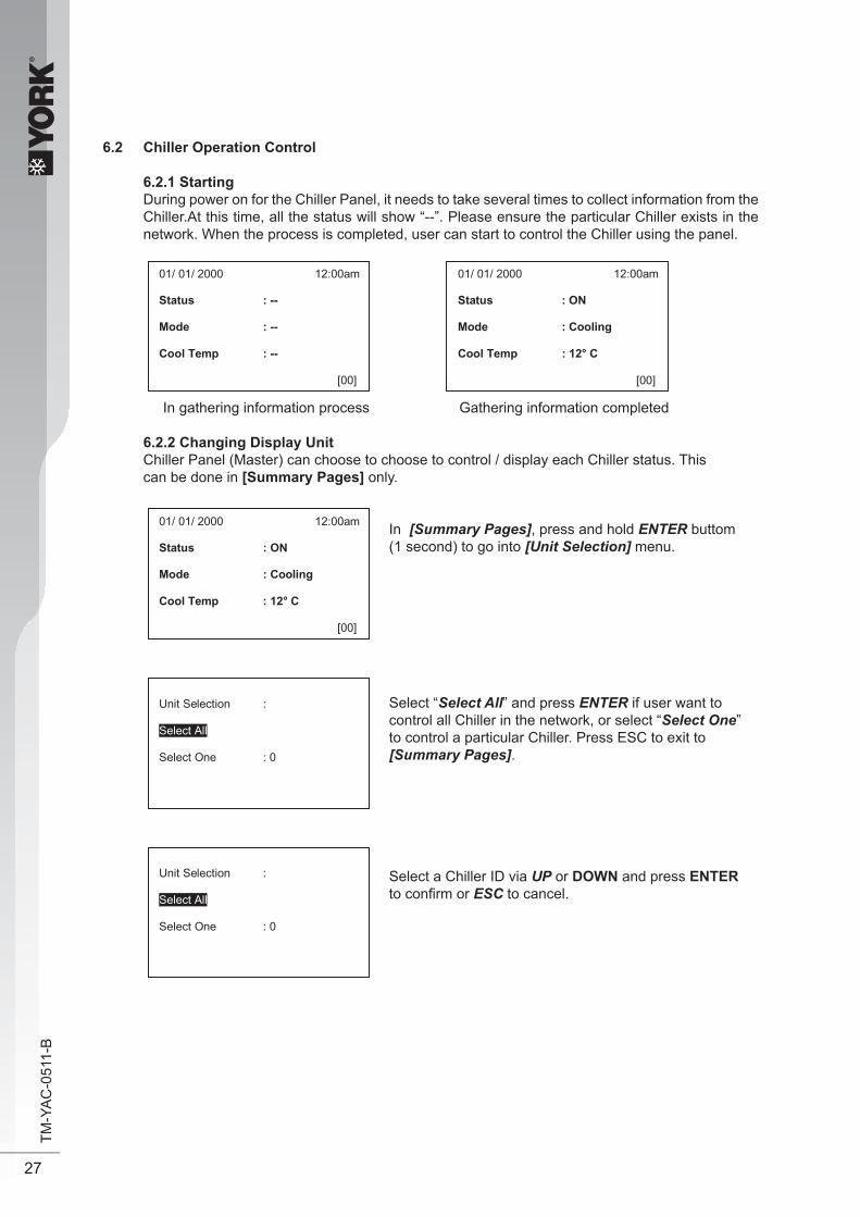
6.2 Chiller Operation Control
6.2.1 Starting During power on for the Chiller Panel, it needs to take several times to collect information from the
Chiller.At this time, all the status will show “--”. Please ensure the particular Chiller exists in the network. When the process is completed, user can start to control the Chiller using the panel.
In gathering information process Gathering information completed
6.2.2 Changing Display Unit Chiller Panel (Master) can choose to choose to control / display each Chiller status. This can be done in [Summary Pages] only.
In [Summary Pages], press and hold ENTER buttom (1 second) to go into [Unit Selection] menu.
Select “Select All” and press ENTER if user want to control all Chiller in the network, or select “Select One” to control a particular Chiller. Press ESC to exit to [Summary Pages].
Select a Chiller ID via UP or DOWN and press ENTER toconfirmor ESC to cancel.
01/ 01/ 2000 12:00am
Status : --
Mode : --
Cool Temp : --
[00]
01/ 01/ 2000 12:00am
Status : ON
Mode : Cooling
Cool Temp : 12° C
[00]
Unit Selection :
Select All
Select One : 0
01/ 01/ 2000 12:00am
Status : ON
Mode : Cooling
Cool Temp : 12° C
[00]
Unit Selection :
Select All
Select One : 0

®
28
TM-Y
AC
-051
1-B
6.2.3 Switching ON/OFF There are several ways to switch ON/OFF for the Chiller.
i) [Summary Pages]
Press and hold ON/OFF button (hold 1 second). Please note that the ON/OFF button will only function in [Summary Pages].
ii) [Operation Menu]
In [Operation Menu], select “Status” and press ENTER.
Toggle ON/OFF via UP or DOWN button, and then press ENTER to confirm the change or ESC to cancel.
iii) [Timer Menu]
7daysprogrammabletimecanturnchillerON/OFF.Usercansetthescheduleinthis [Timer Menu]. Please refer 6.2.11 (page 27) for schedule settings.
OPERATION MENU Status : ON Mode : Cooling Cool Temperature : 12.0° C
OPERATION MENU Status : ON Mode : Cooling Cool Temperature : 12.0° C
>RETNE<>RETNE<
uneMniaMsegaPyrammuS
>CSE<>CSE<
>RETNE<>RETNE<
iaMsegaPyrammuS uneMnoitarepOuneMn
>CSE<>CSE<
Timer Menu

®
29
TM-Y
AC
-051
1-B
6.2.4 Clock Setting Usercansettheclockforthepanel.
UP or DOWN to change ‘hour’. ENTER to set ‘minute’ or ESC to exit to [Timer Menu].
UP or DOWN to change ‘minute’. ENTER to confirm or ESC to set ‘hour’again.
6.2.5 Date Setting Usercansetthedateforthepanel.
UP or DOWN to change ‘year’. ENTER to set ‘month’ or ESC to exit to [Timer Menu].
UP or DOWN to change ‘month’. ENTER to set ‘day’ or ESC to set ‘year’ again.
UP or DOWN to change ‘day’. ENTER to confirm or ESC to set ‘month’ again.
Set Time :
hh mm
00 : 00
Set Time :
yyyy hh mm
2000 /01 / 01
>RETNE<>RETNE<uneMremiTuneMniaMsegaPyrammuS
>CSE<>CSE<<ENTER> <ESC>
Set Time
>RETNE<>RETNE<uneMremiTuneMniaMsegaPyrammuS
>CSE<>CSE<<ENTER> <ESC>
Set Time

®
30
TM-Y
AC
-051
1-B
6.2.6 7 days Programmable Setting The are 2 ON/OFF events in one day for the schedule. This schedule is applicable to all the chillers in the network.
UP or DOWN select day of week, ENTER to select event or ESC to exit to [Timer Menu].
UP or DOWN select event. ENTER to startsetting or ESC to back to select day of week.
Event setting is same like time setting. User candisable the event by set it to ‘- - - -’
Select “Timer” and press ENTER to start the settings. UP or DOWN to toggle Enable/ Disable, ENTER to confirm or ESC to cancel.
Before the schedule will carry the effect, user need to set ENABLE for “TIMER” in [Timer Menu].
Timer 1 Timer 2 ON OFF ON OFF
Sun 0800 1600 _ _ _ _ _ _ _ _ Mon 0800 1600 _ _ _ _ _ _ _ _ Tue 0800 1600 _ _ _ _ _ _ _ _ Wed 0800 1600 _ _ _ _ _ _ _ _
Timer 1 Timer 2 ON OFF ON OFF
Sun 0800 1600 _ _ _ _ _ _ _ _ Mon 0800 1600 _ _ _ _ _ _ _ _ Tue 0800 1600 _ _ _ _ _ _ _ _ Wed 0800 1600 _ _ _ _ _ _ _ _
TIMER MENU
Set Time Set Date Set Schedule Timer : Disable
>RETNE<>RETNE<uneMremiTuneMniaMsegaPyrammuS
>CSE<>CSE<<ENTER> <ESC>
Set Schedule
®
31
TM-Y
AC
-051
1-B
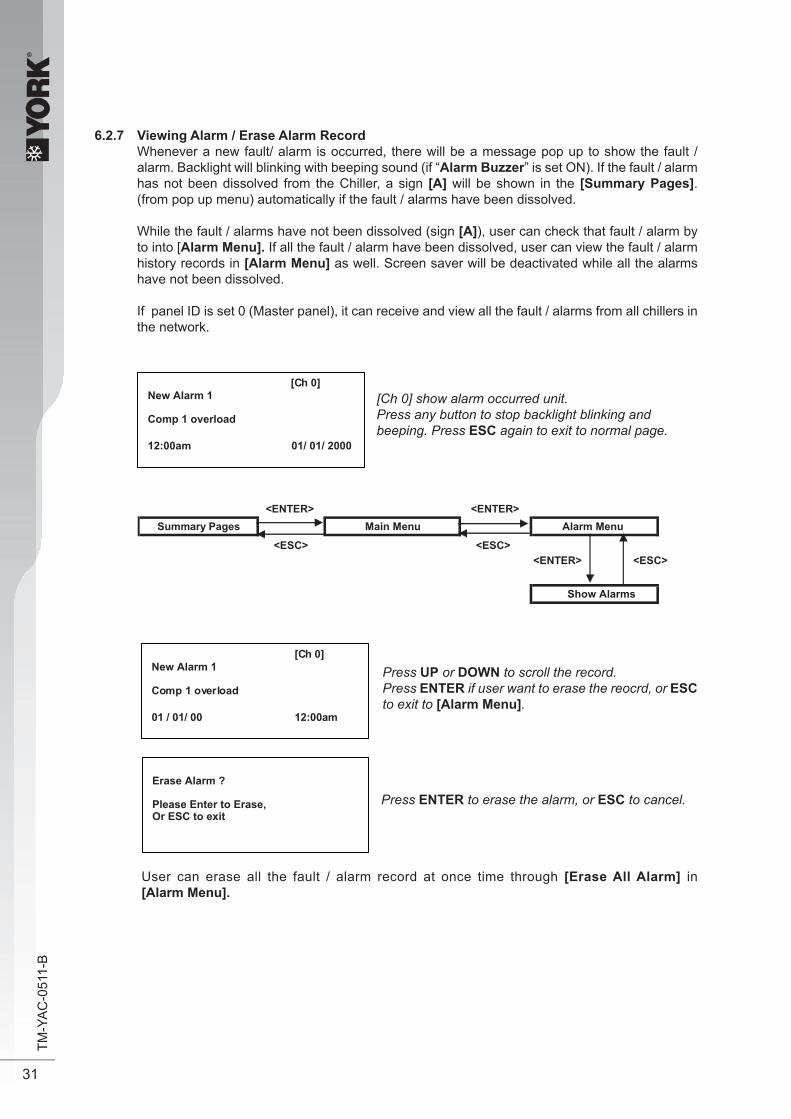
6.2.7 Viewing Alarm / Erase Alarm Record Whenever a new fault/ alarm is occurred, there will be a message pop up to show the fault /
alarm. Backlight will blinking with beeping sound (if “Alarm Buzzer” is set ON). If the fault / alarm has not been dissolved from the Chiller, a sign [A] will be shown in the [Summary Pages]. (from pop up menu) automatically if the fault / alarms have been dissolved.
While the fault / alarms have not been dissolved (sign [A]), user can check that fault / alarm by to into [Alarm Menu]. If all the fault / alarm have been dissolved, user can view the fault / alarm history records in [Alarm Menu] as well. Screen saver will be deactivated while all the alarms have not been dissolved.
If panel ID is set 0 (Master panel), it can receive and view all the fault / alarms from all chillers in the network.
[Ch 0] show alarm occurred unit.Press any button to stop backlight blinking andbeeping. Press ESC again to exit to normal page.
Press UP or DOWN to scroll the record.Press ENTER if user want to erase the reocrd, or ESC to exit to [Alarm Menu].
Press ENTER to erase the alarm, or ESC to cancel.
User can erase all the fault / alarm record at once time through [Erase All Alarm] in [Alarm Menu].
[Ch 0] New Alarm 1
Comp 1 overload
12:00am 01/ 01/ 2000
[Ch 0] New Alarm 1
Comp 1 overload
01 / 01/ 00 12:00am
Erase Alarm ?
Please Enter to Erase, Or ESC to exit
>RETNE<>RETNE<Alarm MenuuneMniaMsegaPyrammuS
>CSE<>CSE<<ENTER> <ESC>
Show Alarms

®
32
TM-Y
AC
-051
1-B
6.2.8 Viewing Defrost Sensor Temperature The Chiller Panel displays defrost sensor temperature for each compressor in [Defrost Sensor] in [Display Menu].
Press ESC to exit to [Display Menu]
6.2.9 Viewing Compressor Discharge Temperature The Chiller Panel displays compressor discharge temperature for each compressor in [Discharge Sensor] in [Display Menu].
Press ESC to exit to [Display Menu]
Defrost Sensor
Comp 1 : 12.8° C
Discharge Sensor
Comp 1 : 36.5 ° C
>RETNE<>RETNE<Display MenuuneMniaMsegaPyrammuS
>CSE<>CSE<<ENTER> <ESC>
Defrost Sensor
>RETNE<>RETNE<Display MenuuneMniaMsegaPyrammuS
>CSE<>CSE<<ENTER> <ESC>
Discharge Sensor

®
33
TM-Y
AC
-051
1-B
6.2.10 Viewing/ Clear Compressor Run Time Usercanview/clearthecompressorruntimefortheChillerin[Comp Run Time] in [Display Menu].
6.2.11 Miscellaneous Settings Usercandosomemiscellaneoussettingstothepanel.
Press UP or DOWN to select the item. ENTER to set, or ESC to exit to [Settings Menu].
Press UP or DOWN to toggle the value. ENTER to confirm, or ESC to cancel.
Comp Run Time Comp 1 : 13579h
Clear Run Time ? Press Enter to Clear Or ESC to exit.
Backlight : Normal : Buzzer : On Screen Saver : Disable Timeout : 5m Contrast : 50% Brightness : Medium Temp Unit : ° C
>RETNE<>RETNE<Display MenuuneMniaMsegaPyrammuS
>CSE<>CSE<<ENTER> <ESC>
Comp Run Time
>RETNE<>RETNE<Settings MenuuneMniaMsegaPyrammuS
>CSE<>CSE<<ENTER> <ESC>
Panel Option
Press UP or DOWN to select teh compressor.ENTER to start clear the run time, or ESC to exit to [Display Menu].
Press ENTER and key in the password to confirm or ESC to cancel

®
34
TM-Y
AC
-051
1-B
CMOS is resetting …………
CMOS reset completed !
Please remove JUMPER and restart the panel
Parameter Value DescriptionNormal Turn ON backlight for 30s via key pressAlways Always ON backlight
derruccomrala/tluafnehwdnuosgnipeebelbanENOderruccomrala/tluafnehwdnuosgnipeebelbasiDFFO
Enable Show screen saver when timeoutDisable No screen save
*Timeout 1-30m Timeout for showing screen saverContrast 0-100% Adjust the contrast setting for the LCD panel
thgilkcaboNFFOLow, Medium, High Adjust the backlight intensity
suisleCeergednierutarepmetyalpsiDC°tiehnerhaFeergednierutarepmetyalpsiDF°
Temp Unit
Backlight
Buzzer
*Screen Saver
Brightness
* This product must be branded. Screen saver will be deactivated for brand less panel
6.3 CMOS Reset
• CMOS reset allows user to reset some settings to default value such as:
Password -> 0001 Backlight -> Normal Buzzer -> ON Screen Saver -> Disable Timeout -> 5m Contrast -> 50% Brightness -> Medium TempUnit ->C
• Procedures 1. Power OFF the panel 2. Close the jumper JH2 with the provided jumper header 3. Power ON the panel and the LCD panel should display as follow:
4. Remove the jumper header (put the jumper header on 1 pin only), power OFF and then power ON the panel.

®
35
TM-Y
AC
-051
1-B
7. Problem And Troubleshooting
Symptoms Possible Cause Troubleshooting1 Panel gets hot - Wiring fault in 12VDC supply - Change a new panel module and turn ON the unit again
noitacifirevehtretfayllamronba2 The LCD no display - Wiring fault in 12VDC supply - Correct the wiring problem
(blank screen) - No power supply - Check the wiring and supply 12VDC to panel- Voltage supply too low - Check the power source- Module defective - Change a new panel module
3 - -' for all status -Panel cannot/ not yet - Ensure the selected unit exits in the network(quite a long time) received the information - Ensure the wiring is correct
from chiller or FCU completely - Ensure the wiring is not defective- Ensure the wiring has been isolated from high power cable
- That particular unit address - Select a coherent unit address on the panel (refer to 6.2.2) is not recognized by the panel - Module defective - Change a new module
5 Cannot step inside - Software limitation. Panel has - Refer to symptoms 3[Set Parameter] not received all the information
from chiller completely6 7 Days Programmable - Software limitation. User Control of Chiller:
Timer not function did not activate the schedule - Ensure the "Timer" in [Timer Menu] is set ENABLEControl of Chiller:
- Ensure the 'Timer" in [Operation Menu] is set ENABLE7 No beeping sound - Software limitation. User - Ensure "Buzzer" in [Panel Option] is set ON
when new alarm did not set ON to the alarm occurred buzzer
8 No screen saver after - Software limitation. User did - Ensure "Screen Saver" in [Panel Option] I set ENABLEtimeout not set ENABLE to the screen
saver
9 Time always reset to - No backup battery - Replace coin cell battery12:00am, 1st Jan 2000 - Energy of the backup battery is
low10 Panel stop operation. - Unstable power supply - Power off the panel. Take out the backup battery as well.
Whole operation - Energy of the backup battery is Replace with a new 3V coil cell battery if necessary. Putniaganorewopdnalenapehtotniyrettabpukcabehtkcabwol)gnah(gnizeerf

®
36
TM-Y
AC
-051
1-B
8. Appendix
noituloseRxaMniMtluafeDtinUepyTROSNESS1 Entering water sensor calibration U °C (F) 0 (0) -12 (21.6) -12 (21.6) 0.1S2 Leaving water sensor calibration U °C (F) 0 (0) -12 (21.6) -12 (21.6) 0.1
1.0)6.12( 21-)6.12( 21-)0( 0)F( C°Unoitarbilac rosnes riA3SS4 Defrost(condenser) sensor 1 calibration U °C (F) 0 (0) -12 (21.6) -12 (21.6) 0.1S5 Defrost(condenser) sensor 2 calibration U °C (F) 0 (0) -12 (21.6) -12 (21.6) 0.1S6 Defrost(condenser) sensor 3 calibration U °C (F) 0 (0) -12 (21.6) -12 (21.6) 0.1S7 Defrost(condenser) sensor 4 calibration U °C (F) 0 (0) -12 (21.6) -12 (21.6) 0.1S8 Compressor discharge sensor 1 calibration U °C (F) 0 (0) -12 (21.6) -12 (21.6) 0.1S9 Compressor discharge sensor 2 calibration U °C (F) 0 (0) -12 (21.6) -12 (21.6) 0.1S10 Compressor discharge sensor 3 calibration U °C (F) 0 (0) -12 (21.6) -12 (21.6) 0.1S11 Compressor discharge sensor 4 calibration U °C (F) 0 (0) -12 (21.6) -12 (21.6) 0.1
noituloseRxaMniMtluafeDtinUepyTlareneG1204galFFledoM
0=Chiller (Chiller+Boiler)1=Heat pump,2=Chiller/ Boiler,3=Heat pump/ Boiler, 4=Chiller+Boiler5=Heat pump+Boiller
1411galFFrosserpmoc fo rebmuN1=1 compressor,2=2 compressor,3=3 compressor,4=4 compressor
110)elbasid( 0galFFtupni ffO/nO0=disable, 1=enable
110)elbasid( 0galFFtupni taeH /ooC0=disable, 1=enable
110)elbasid( 0galFFtupni mrala lanretxE0=disable, 1=enableWater system for chiller network F Flag 0 (disable) 0 1 10=independent, 1=modular
10500galFFrebmun tinU7G
G5
G6
G1
G2
G3
G4
noituloseRniMxaMtluafeDtinUepyTROSSNEDNOC12D)4-( 02-)23( 0)F( C°Uerutarepmet tsorfed tratS1D1)401( 041D)75( 41)F( C°Uerutarepmet tsorfed dnE2D
D3 Maximum duration of defrost cycle U min 10 1 40 11991054nimUemit lavretni tsorfeD4D01099100cesUgnitsorfed erofeb yaleD5D0109910021cesUgnitsorfed retfa yaleD6D

®
37
TM-Y
AC
-051
1-B
noituloseRxaMniMtluafeDtinUEZEERFITNA EDOM LOOC1)401( 04)04-( 04-)14( 5)F( C°tniop-tes retaeh ezeerfitnA1A
1.0)81( 01)7.0( 4.0)6.3( 2)F( C°laitnereffid retaeh ezeerfitnA2A1100galFtceles rosnes ezeerfitnA3A
)gnivael(retaw gniretnE=1 ,retaw gnivaeL=01)401(04)04-( 04-)73( 3)F( C°tniop-tes mrala ezeerfitnA4A
1.0)81( 01)7.0( 4.0)6.3( 2)F( C°laitnereffid mrala ezeerfitnA5A
noituloseRxaMniMtluafeDtinUTCATNOC DNA MRALA199105cesemit noitamrifnoc hctiws wolF1P
P2 Flow switch alarm delay at pump start sec 120 0 199 1P3 Low pressure alarm delay at compressor start up sec 30 0 199 1
1100galFepyt teser mrala daolrevo pmoC4P)launam(teser otuA=1 ,teser launaM=0
1101galFepyt teser mrala erusserp hgiH5P)otua(teser otuA=1 ,teser launaM=0
1101galFteser mrala erusserp woL6P)otua(teser otuA=1 ,teser launaM=0
1101galFepyt teser mrala daolrevo naF7P)otua(teser otuA=1 ,teser launaM=0
1100galFepyt teser mrala daolrevo pmuP8P)launam(teser otuA=1 ,teser launaM=0
1100galFepyt teser mrala hctiws wolF9P)launam(teser otuA=1 ,teser launaM=0
1101galFepyt teser mrala yrailixuA01P)otua(teser otuA=1 ,teser launaM=0
1101galFepyt teser mrala ezeerfitnA11P)otua(teser otuA=1 ,teser launaM=0
1100galFepyt tcatnoc daolrevo pmoC21P)CN()ON(nepo yllamroN=1 )CN(esolc yllamroN=0
1100galFepyt tcatnoc erusserp hgiH31P)CN()ON(nepo yllamroN=1 )CN(esolc yllamroN=0
1100galFepyt tcatnoc erusserp woL41P)CN()ON(nepo yllamroN=1 )CN(esolc yllamroN=0
1100galFepyt tcatnoc daolrevo naF51P)CN()ON(nepo yllamroN=1 )CN(esolc yllamroN=0
1100galFepyt tcatnoc daolrevo pmuP61P)CN()ON(nepo yllamroN=1 )CN(esolc yllamroN=0
1100galFepyt tcatnoc hctiws wolF71P)CN()ON(nepo yllamroN=1 )CN(esolc yllamroN=0
1100galFepyt tcatnoc mrala lanretxE81P)CN()ON(nepo yllamroN=1 )CN(esolc yllamroN=0
1100galFepyt tcatnoc dne tsorfeD91P)CN()ON(nepo yllamroN=1 )CN(esolc yllamroN=0

®
38
TM-Y
AC
-051
1-B
6. Installation
Installations
YAC 20/25/30C
YAC 40/50/60C

®
39
TM-Y
AC
-051
1-B
YAC 80/100/120/150C
005005500
1500AI
R F
LOW
AIR FFLOW
AIR FFLOW
MIN
500
YAC 20/25/30/40/50/60C
For single unit installation

®
40
TM-Y
AC
-051
1-B
! Warning
IMPORTANTDO NOT INSTALL OR USE THE AIR CONDITIONER UNIT IN A LAUNDRY ROOM
• Installation and maintenance should be performed by qualified persons who are familiarwith local code and regulation, and experienced with this type of appliance.
• All field wiring must be installed in accordance with the national wiring regulation.• Ensure that the rated voltage of the unit corresponds to that of the name plate before
commencing wiring work according to the wiring diagram.• The unit must be GROUNDED to prevent possible hazards due to installation failure.• All electrical wiring must not touch the refrigerant piping, compressor or any moving parts
of the fan motors.• Confirm that the unit has been switched OFF before installing or servicing the unit.• Do not touch the compressor or refrigerant piping without wearing gloves.
500 1000 0050001
1500
AIR
FLO W
A IR
FLOW
AIR
FLO W
AIR FLOW
AIR FLOW
AIR FLOW
AIR FLOW
MIN 500
50 50
100
SAFETY PRECAUTIONSBefore installing the air conditioner unit, please read the following safety precautions carefully
For multiple unit installation (mm)
For floor installation (mm)
YAC 20/25/30/40/50/60C

®
41
TM-Y
AC
-051
1-B
CautionPlease take note of the following important points when installing.
• Do not install the unit where leakage of flammable gas may occur.
If gas leaks and accumulates around the unit, it may cause fire ignition.
• Ensure that the drainage piping is connected properly.
If the drainage piping is not connected properly, it may cause water leakage which will dampenthe furniture.
• Do not overcharge the unit.
This unit is factory pre-charged. Overcharge will cause over-current or damage to the compressor.
• Ensure that the units panel is closed after service or installation.
Unsecured panels will cause unit to operate noisily.
Installation Location• Installation work should be done by the authorized dealer or qualified contractor. Never install
the unit yourself.• Make sure there is sufficient airflow around the unit.• Vibration isolator should be provided to reduce the vibration and noise of the unit.• There should be sufficient space allocated for servicing and maintenance when installing the unit.
Transportation• The unit should be lifted using a crane. Ensure that the hanger belts are not touching the coil, top panel and front panel (use protective panel)
as shown in Figure 1.• The bolt of the base and channel support can be removed after putting the unit on the fixed location.
Figure 1Water Piping And Fitting• All water pipe must be insulated to prevent capacity losses and condensation.• Install a 40-60 mesh strainer to ensure water quality is good.• Water pipe recommended are black steel pipe and copper pipe.• During installation, the piping of the unit should be clamp before rotating the installation pipe to reduce
the moment induce on the unit piping.• Users are recommended to install the pipe and accessories as shown in Figure 2 & 3.• An air vent must be installed at the highest position, while a drainage plug at the lowest position of
the water circuit. Open the air vent to release any air trap in the water circuit.• Run the clean water through the water inlet and operate the pump to drain out the dirty water.
Clean the strainer after running the pump for 30 minutes.• Fill up the water circuit after connecting the pipes and equipment. Check water leakage at all
connections and joints. Do not start the unit when the system is leaking.• To optimize the capacity of the system, ensure that the system is free of air bubbles. The air trapped
in the system would make the system unbalanced.
!
!

®
42
TM-Y
AC
-051
1-B
P
PP
PRESSURE GAUGE
GATEAAVALVE
GATEAAVALVE
BALANCINGVALVETHERMOMETER
FLEXIBLE GATE VAA AVV LVE (LOWERLLPOSITION FOR DRAINAGE)
AIRVENT (INSTALLTTHIGHEST POSITION)
FAN COIL UNIT/AIR HANDLING UNITL
GATEAAVALVE
THERMOMETER GATE VEAA AVV LVLL E GATE VAA AVV LVLL EVALVE
STRAINER
CHECKVALVE
MAKE UPVALVE
BYPP AALVLL E(DIFFER ENT
PRESSURE GAUGE
GAAVA E
GAATHERMOMETER
FLEXIBLE AALVE (LOWERLL
AIRVENT (INSTALLTTHIGHEST POSITION)
FAN COIL UNIT/AIR HANDLING UNITL
GATEAAVALVE
THERMOMETER AALVLL E VALVE
STRAINER
VALVLL E
MAKE UPVALVE
BYPP AALVLL(DIFFER ENT TYPE)
YAC 20/25/30C
YAC 40/50/60C
YAC 80/100/120/150C
• Do not allow water to remain in the water pipes if the unit is not operating for a long period. Water must be drained out if the unit is not running during winter. Failing to do so would cause the pipe to crack.• Do not drink the chilled water in the unit.
CAUTION
Figure 2
PRESSURE GAUGE
GATEVALVE
GATEVALVE
BALANCINGVALVETHERMOMETER
FLEXIBLE GATE VALVE(LOWER POSITIONFOR DRAINAGE)
AIRVENT (INSTALLHIGHEST POSITION)
FAN COIL UNIT/AIR HANDLING UNIT
GATEVALVE
Figure 3
THERMOMETER GATEVALVE
GATEVALVE
BALANCINGVALVE
STRAINER
CHECKVALVE
MAKE UPVALVE
PRESSUREDIFFERENTIAL
VALVEFLEXIBLE

®
43
TM-Y
AC
-051
1-B
Electrical And Wiring
Remove this wirewhen doingwiring for fanspeed controller
Wiring for fanspeed controller(FS C ) FS C
OF IN OF OUTTB3
TB3 OF IN OF OUT
TO (PC B)OUT_FAN1
TO (A) OUT_FAN 1C APAC ITOR
Power supply 400V / 3Ph-N / 50Hz
L1 N
TB1 R S T N
L2 L3
TB3
Power supply 230V / 1Ph-N / 50Hz
Remove this wirewhen doing wiringfor fan speedcontroller
Figure 8
OF IN OF OUT
OF IN OF OUT
Wiring for fanspeed controller(FS C )
FS C
TB3
TO (PC B)OUT_FAN1
TO (A) OUT_FAN 1C APAC ITOR
L1 N
TB1 L/L1 N/L2
15 Nm
• Refer to the wiring diagram provided on the unit when making electrical wiring.• Install an isolator (optional) to prevent electrical shock.• Do not ground any electrical equipment to the water piping. • Operation of the mini chiller without any fan speed controller (Field supply) is limited to an ambient
temperature of 20˚C. With the fan speed controller (Field supply), the unit is able to operate down to -5˚C. All mini chillers will have a 1/4” access valve provided for along the liquidline of the refrigerant circuit.This valve is for direct pressure connectionto the fan speed controller. To install the fan speed controller, screw inthe female adaptor to the 1/4” access valve. Use a pair of spanners totighten properly(max. torque 15Nm). See Fig. 8. Ensure there is no leakage atthe joint. Wire the fan speed controller to the terminal blocks.
YAC 20/25/30C
YAC 40/50/60C
FM1 FM2 OF1 OF2
FS C 1
FS C 2
4WV2
4WV1
HTR ALLIN
ALL FM1 FM2 OF1 OF2 C / H ON/ OFF
OFF ON CH
12 VDC or 230V AC
Power supply 415V / 3Ph-N / 50Hz
Wiring for fan speedcontroller (FS C )
Remove these wireswhen do wiring for fanspeed controller
YAC 80/100/120/150C

®
44
TM-Y
AC
-051
1-B
Recommended Fuse And Cable Sizes
Model YAC 20C YAC 25C YAC 30C YAC 40C
Voltage range ** 220-240V/1Ph/50Hz + N + 380-415V/3Ph/50Hz + N +
Recommended fuse * A 27 38 45 22 Power supply cablesize * mm2 Numbers of conductor
10 3
10 3
10 3
5 5
Interconnection cable size * mm2 1.5 1.5 1.5 1.5
Model YAC 50C YAC 60C
Voltage range ** 380-415V/3Ph/50Hz + N +
Recommended fuse * A 24 29 Power supply cable size * mm2
Numbers of conductor 5 5
5 5
1.5 1.5 Interconnection cable size * mm2 1.5 1.5
Model YAC 80C YAC 100C YAC 120C YAC 150C
Voltage range ** 380-415V/3Ph/50Hz + N +
Recommended fuse * A 35 40 50 60 Power supply cable size * mm2
Numbers of conductor 10 5
10 5
10 5
10 5
Interconnection cable size * mm2 1.5 1.5 1.5 1.5
IMPORTANT : * The figures shown in the table are for information purpose only. They should be checked and selected to comply with the local/national codes of regulations. This is also subjected to the type of installation and conductors used. ** The appropriate voltage range should be checked with label data on the unit.
• All field wiring must be installed in accordance with the national wiring regulation. • All the terminals and connections must be tightened. Improper connection and fastenings could cause electric
shock, short circuit and fire. • Ensure that the rated voltage of the unit corresponds to that of the name plate before commencing wiring work
according to the wiring diagram. • The unit mus be GROUNDED to prevent possible hazards due to insulation failure. • All electrical wiring must not touch the refrigerant piping, compressor, pump, fan motor or any moving parts of the
fan motors. • Do not operate the chiller with wet hands. It would result in electric shock. • Do not use fuse of different amperage than stated. Using wire etc. to replace a fuse could cause equipment
damage or fire.
! CAUTION

®
45
TM-Y
AC
-051
1-B
• All terminals and connection must be tightened.• Avoid any wires from touching the refrigerant pipe. Apply insulation if necessary.• Avoid any wires from touching the moving components such as, fan motor, pump & compressor.
Water Piping System Setup
Refrigerant Circuit
Safety And Caution
WARNING
• Fill up the water circuit after connecting all the pipes and equipment. Perform leak checks for all connections and joints. Do not start the unit when the system is leaking.
• To optimize the capacity of the system, ensure that the system is free of air bubbles. The air trapped in the system would make the system unbalanced.
• Ensure that the water tank (optional) is not full. This is to ensure optimal performance of the mini chiller. If the pressure is too high, release the air trapped from the auto air vent (on the tank) and manual air vent (installed on the water system).
• All mini chillers units are pre-charged with R22 refrigerant. The only piping that needs to be done is the water piping from mini chiller (outdoor) to the fan coil unit (indoor).
It is advisable to read through all the safety precautions before installing and commissioning of the unit.• Contact your dealer for installation, reinstallation or dismantling of unit. Improper handling of unit could
result in leaks, electrical shock or unit malfunction.• Use the controller handset to switch on/off the unit. Do not plug off the Main power supply directly, it
would cause the unit to breakdown.• Improper connections and fastening could cause electric shock, short circuit and fire.• Do not introduce foreign objects such as fingers, sticks etc. Into the air inlet and outlet.• Do not spray any chemical agents or flammable agents to the unit. It would cause fire or explosion.• Do not climb or place objects on top of the mini chiller.• Do not operate the chiller with wet hands. It would result in electric shock.• Do not use fuse of different amperage than stated. Using wire, Etc. To replace a fuse could cause
equipment damage or fire.• Provide proper grounding for the mini chiller. Do not connect the ground wire to gas piping, water
piping, lighting rods or telephone ground wire. Improper grounding could cause electrical shock.• Do not attempt to do any service or maintenance when unit is operating.• Do not change the settings of the safety devices.• Do not consume the chilled water in the unit.• Do not allow water to remain in the water pipes if the unit is not operating for a long period. Water must
be drained out if the unit is not running during winter. Failing to do so would cause the pipe to crack. • Do not touch the aluminum fin coil. It would damage the coil or cause injury.

®
46
TM-Y
AC
-051
1-B
Control Operation GuideThe unit is equipped with a microprocessor controller board. The microprocessor controller is provided to give temperature control for the system by accurately measuring the ambient temperature, and controlling the water entering and water leaving temperature. The temperature setting in the unit is preset in the factory. It is not recommended to change the setting unless necessary. A wired controller handset is connected to the microprocessor board. Every parameter setting and reading can be observed from the LCD of the handset.
1. Handset location The handset is located on a metal bracket behind the right door panel.2. LED Display (microprocessor board) The keypad LED will light up when the unit is turned on.3. LCD display (controller handset) During normal operations, the LCD can display the entering water temperature, the leaving water
temperature, the entering water setpoint temperature, compressor on or off status and outdoor air temperature. When malfunctioning occurred, the LCD would blink. The display would show the faulty parameter and the date and time of the occurance.
4. Controller functioning specification There is a 3 minute delay for the compressor and fan motor to restart (default setting).

®
47
TM-Y
AC
-051
1-B
7. Wiring Diagrams
Model: YAC 20C

®
48
TM-Y
AC
-051
1-B
Model: YAC 25/30C

®
49
TM-Y
AC
-051
1-B
Model: YAC 40/50/60C
®
50
TM-Y
AC
-051
1-B
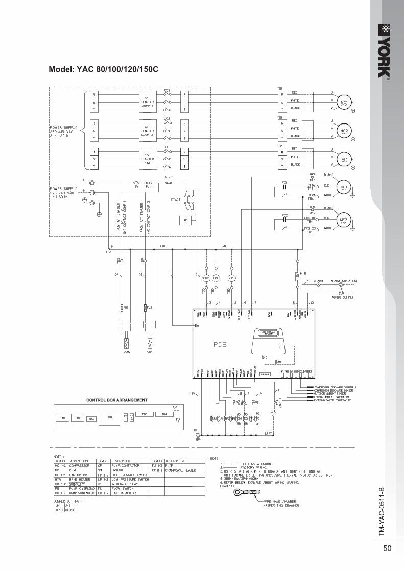
Model: YAC 80/100/120/150C
®
51
TM-Y
AC
-051
1-B
8. Servicing & Maintenance
ServicingServicing or maintenance of these unit must be carried out by experienced personnel with specific training in refrigeration. Repeated check the safety devices and continuous cycling of control components must be analyzed and corrected before being reset.
The simple design of the refrigeration circuit totally eliminates potential problems during normal unit operation. No maintenance work is needed on the refrigeration circuit as long as the unit is operating normally.
Ease of maintenance has been taken into consideration during the design stage such that the unit is easily accessible for servicing and maintenance. By accessing from the front panel of the unit, servicing and maintenance operation can be done easily. The electrical components are especially easy to access since it is located in the terminal box on top of the front panel.
Under normal circumstances, these chiller require only a check and cleaning of air intake through the coil surface only. These can be done monthly or quarterly depending on the surrounding where the units are installed.
When the surrounding is very oily or dusty, then the coils must be regularly cleaned by a qualified air conditioner service technician to ensure sufficient cooling capacity and efficient unit operation. The normal life span might be shortened if no proper service is provided.
MaintenanceFor consistent performance and durability, always conduct proper and regular maintenance to the unit.
For prolong period of operation time, the heat exchanger will become dirty impairing its effectiveness and reducing the performance of the units. Consult your local dealer about the cleaning of the heat exchanger.
No major maintenance or servicing needed for the internal water circuit in the unit except the water pump failure. It is advised that regular check on the filter to be conducted and change the water filter if the filter is dirty or choked.
Always check the water level in the system, in order to protect the moving components in the hydraulic kit from over heating and excessive wear.

®
52
TM-Y
AC
-051
1-B
Phase Proctector (Optional)
Notes: 1. “+” indicates additional for PP01 phase proctector. 2. When R phase missing. no LED or buzzer will indicate the error, but relay 71 and 81 will cut off.
SYMPTONS PROBLEM CAUSES REMEDIAL ACTION 1. Compressor does
not start. • No power supply. • Fuses blown or automatic circuit
break down open.
• Defective contactor or coil. • Unit is stopped because safety device has tripped.
• Loose wires.
• Compressor faulty.
• Check power supply. • Look for short circuit or grounded
wires in motor windings. Replace fuses and reset circuit breakers when the fault has been corrected. Check tightness and soundness of all electrical connections.
• Repair or replace. • Determine the type of safety shut down and correct the default before the unit is restarted. • Check wire connections and
tighten terminal screws. • Contact local dealer.
2. Fan does not work. • No power supply. • Fan motor faulty.
• Check power supply. • Contact local dealer
3. Unit does work, but insufficient cooling.
• Thermostats setting too high. • Condenser coil dirty. • Obstacle blocking air inlet or outlet of the unit. • Insufficient refrigerant in the
system. • Improper water flow rate, • Water in the system is
contaminated.
• Reset thermostat. • Contact local dealer. • Remove obstacles.
• Contact local dealer.
• Contact local dealer. • Contact local dealer.
4. Flow switch error. • No water in the system. • Low water level in the system.
• Check water supply. • Check water supply.
LED PW P_R P_S P_TDescription (Red) (Yellow) (Yellow) (Yellow)
Normal operation ○ ● ● ●
● ● ● ●
● ● ●
-
Reverse phase Switch off the unit. Check the 3 phase wiring.
T phase missing ● ● Switch off the unit. Check the 3 phase wiring.
S phase missing ● ● Switch off the unit. Check the 3 phase wiring.
R phase missing Switch off the unit. Check the 3 phase wiring.
S & T phase missing + ● Switch off the unit. Check the 3 phase wiring.
Overload + High discharge temperature. Check the refrigerant system.
Sensor missing + ○ ○ ○ Switch off the unit. Plug in sensor.
Actions
○ On ● Off Fast Blink
When any malfunction is occurred, immediately switch off the power supply to the unit, and contact the local dealer, if necessary. Some simple troubleshooting tips are given below:
The unit with Scroll Compressor can only rotate in one direction. For this reason, a protective device (phase proctector) is fitted to prevent incorrect wiring of the electrical phases. When the three phases are not connected correctly, the phase protector operates, and the unit will not start. This devise is located in the control box of model YAC 80~150C.
The following tables shows the LED indicator light for phase proctector under normal operation and fault conditions.
9. Troubleshooting

®
53
TM-Y
AC
-051
1-B
10. Dimensional Data
Model : YAC 20/25/30C
1181,6 0,010,01
460,0
85,0 128,5
WATERINLET
DRAINAGE
WATEROUTLET
128,5
789,
5
475,
055
,2
80,0
300,
080
,0
1181,6
460,0
85,0 128,5
0,510,51
300,
079
,7
20,0
80,3
1160,0
1409
,4
878,
8
WATERINLET
DRAINAGE
WATEROUTLET
Model: YAC 40/50/60C
All Dimensions are in mm
All Dimensions are in mm

®
54
TM-Y
AC
-051
1-B
Model: YAC 80/100/120/150C
A
C D
L LG
K
M I J
HHB
WAWW TERAAOUTLET
WAWW TERAAINLET
FE
All Dimensions are in mm
F G Model A B C D E Base Leg Hole YAC 80CYAC 100C 1500 900 1245 1190 297.5 307.5 1446 YAC 120C 1800 1150 1245 1190 347.5 416 1776 YAC 150C 1800 1150 1245 1190 347.5 416 1776
H I J K L M 100 265 385 60 200 170 100 265 385 60 200 170100 265 385 60 200 170100 265 385 60 200 170
1500 900 1245 1190 297.5 307.5 1446

®
55
TM-Y
AC
-051
1-B
Accessory Hydraulic Kit (Optional)
Weight = 92kgMaterial of water tank = Mild steel with 3mm thicknessPipe Connection = 1 - 1/4”Type of pipes connection = BSPF FemalePacking Dimension = 838 (W) x 788 (D) x 1378 (H)
Hydraulic kit consists of 135L capacity water storage butffer tank, over pressure release value anddrainage point.
The buffer tank is installed at the water return path back to chiller. In order to let the connection look tidy, the tank has a bypass pipe (the center connection) to allow the pipe to be connected to FCU. The additional outlets are sealed (they are meant for installation at different side). Please refer to the exploded view.

®
56
TM-Y
AC
-051
1-B
11. Exploded View And Parts List
Model: YAC 20/25/30C
61419717
1213
24
20
18
5510116
1589
311
ITEM ITEMDESCRIPTION DESCRIPTION
1. ALL SPECIFICATION ARE SUBJECTED TO CHANGE BY THE MANUFACTURER WITHOUT PRIOR NOTICE
1 TOP PANEL 2 STRUCTURE FRONT RIGHT 3 PANRL SUPPORT PILLAR 4 ASSY, PANEL ORIFICE 5 STRUCTURE REAL RIGHT 6 PANEL RIGHT 7 ASSY BASE PAN 8 PANEL PARTITION 9 COILGUIDE BACK 10 COIL GUIDE LEFT 11 ASSY. CONTROL BOX 12 COVER, TERMINAL BOX
13 WATER STORAGE TANK 22L14 HEAT EXCHANGER, BPHE15 CLAMP, BPHE16 ASSY, UNIT TUBING17 ASSY, WATER PIPING18 ASSY, FAN MOTORPARTS NOT SHOWN IN DIAGRAM FILTER DRIER CONTROL MODULE TANK, EXPANSION 2 LITER VALVE, PRESS RELIFT PUMP, WATER

®
57
TM-Y
AC
-051
1-B
Model: YAC 40/50/60C
11
12
13
113 9 1 8 16 15
10
23
20
14
21
18
6
1917
7
2
22
5
4
ITEM ITEMDESCRIPTION DESCRIPTION
1. ALL SPECIFICATION ARE SUBJECTED TO CHANGE BY THE MANUFACTURER WITHOUT PRIOR NOTICE
1 PANEL TOP 2 ASSY STRUCTURE FRONT RIGHT TOP 3 PANEL,SUPPORT PILLAR 4 PANEL ORIFICE 5 ASSY STRUCTURE REAR RIGHT 6 PANEL, RIGHT 7 ASSY BASE PAN 8 PANEL PARTITION 9 ASSY COIL 10 COIL GUARD11 COIL GUARD 11 ASSY. CONTROL BOX 12 COVER, TERMINAL BOX 13 COVER, TERMINAL BOX
14 ASSY, INS WATER STORAGE TANK 40L15 CLAMP, BPHE16 HEAT EXCHANGER, BPHE17 COMPRESSOR18 ASSY, PUMP BASE19 PUMP, WATER20 ASSY, UNIT TUBING21 ASSY, WATER PIPING22 ASSY, FAN MOTOR23 ASSY, S. HOISTING BRACKETPARTS NOT SHOWN IN DIAGRAM CONTROL MODULE MC01 EC VALVE, PRESS RELIFT TANK, EXPANSION 5 LITER

®
58
TM-Y
AC
-051
1-B
Model: YAC 80/100C
33
32
7 1038 9 41 37 36 35
40
26
25
18
21
8
2
24
19
15
31
34
1
27
22
20
3
4111312
14
29
30
28
5
6
16
17
ITEM ITEMDESCRIPTION DESCRIPTION15 ASSY, COIL RIGHT16 ASSY, COIL LEFT17 ACCUMULATOR18 LIQUID RECEIVER19 BRACKET BPHE20 SUPPORT, TUBE21 CLIP, FILTER22 COMPRESSOR23 HEAT EXCHANGER M(4)AC80C24 CLAMP, BPHE25 INS, ACUMULATOR BODY26 INS, LIQUID RECEIVER27 PANEL, TERMINAL BOX SUPPORT28 ASSY. CONTROL BOX
1 ASSY, BASE PAN2 ASSY, INS PARTITION PANEL3 SUPPORT, FLUTTED WIRE4 ASSY, RIGHT PANEL5 ASSY, LEFT PANEL6 PANEL, SUPPORT FRONT7 STRUCTURE BACK L/R8 PANEL, COIL SUPPORT9 PANEL, RIGHT ORIFICE10 PANEL, LEFT ORIFICE11 SUPPORT, EXPANSION TANK12 DOOR HINGE13 ASSY, DOOR PANEL RIGHT 14 ASSY, PANEL DOOR LEFT

®
59
TM-Y
AC
-051
1-B
Model: YAC 80/100C (Continued)
ITEM ITEMDESCRIPTION DESCRIPTIONPARTS NOT SHOWN IN DIAGRAM HANDSET CONTROL MODULE MC01 EC PHASE PROTECTOR LOW PRESSURE SWITCH HIGH PRESSURE SWITCH FILTER DRIER VALVE, TXV M(4) AC80/100C 4 WAYS VALVE M(4) AC80/100C
30 ASSY, PANEL HOOK31 PUMP, WATER32 EXPANSION TANK 8L33 CLAMP, EXPANSION TANK34 ASSY, PANEL PARTITION35 BRACKET, FAN MOTOR36 FAN MOTOR37 FAN BLADE38 FAN GUARD 24”
1. ALL SPECIFICATION ARE SUBJECTED TO CHANGE BY THE MANUFACTURER WITHOUT PRIOR NOTICE

®
60
TM-Y
AC
-051
1-B
Model: YAC 120/150C
33
35
6 2023
38
30
21
31
27
5
2
26
24
23
22
5
34
4
3710
25
191716
18
13
4 5
4
3
14
28
1211
ITEM ITEMDESCRIPTION DESCRIPTION15 ASSY, COIL RIGHT16 DOOR HUNGE17 ASSY, DOOR PANEL RIGHT18 ASSY, PANEL DOOR LEFT19 COMPRESSOR20 ACCUMULATOR21 LIQUID RECEIVER22 BRACKET BPHE23 HEA EXCHANGER24 CLAMP, BPHE25 SUPPORT, TUBE26 CLIP, FILTER27 COIL GUARD, BACK28 COIL GUARD, L/R
1 ASSY, BASE PAN2 ASSY, PANEL PARTITION 3 PANEL, SIDE RIGHT4 PANEL, SIDE LEFT5 PANEL, COIL SUPPORT6 STRUCTURE BACK L/R7 PANEL, CONTROL BOX SUPPORT8 ASSY, CONTROL BOX MAIN9 PANEL, SUPPORT FRONT10 SUPPORT, WIRE FLUTTED11 PANEL, RIGHT ORIFICE12 PANEL, LEFT ORIFICE13 PANEL, FRONT14 ASSY, COIL LEFT

®
61
TM-Y
AC
-051
1-B
Model: YAC 120/150C (Continued)
ITEM ITEMDESCRIPTION DESCRIPTIONPARTS NOT SHOWN IN DIAGRAM CONTROL MODULE HANDSET PHASE PROTECTOR LOW PRESSURE SWITCH HIGH PRESSURE SWITCH FILTER DRIER 4 WAY VALVE VALVE, TXV
29 FAN GUARD 26”30 INS, ACCUMULATOR BODY31 INS, LIQUID RECEIVER BODY32 SUPPORT, EXPANSION TANK33 CLAMP EXPANSION TANK34 PUMP, WATER35 EXPANSION TANK 8L36 BRACKET, FAN MOTOR37 FAN MOTOR38 FAN BLADE
1. ALL SPECIFICATION ARE SUBJECTED TO CHANGE BY THE MANUFACTURER WITHOUT PRIOR NOTICE

Head Office: Tel: 03-7718 8388 Fax: 03-7727 4371 Email: [email protected], [email protected]
Branches: • Penang Tel: 04-331 1670 • Johor Tel: 07-557 7788 • Pahang Tel: 09-567 6778 • Perak Tel: 05-548 2307 • Melaka Tel: 06-288 1133 • Sabah Tel: 088-722 194 • Sarawak Tel: 082-333 299 • Negeri Sembilan Tel: 06-7688969
Service Centre: • Alor Setar • Kota Bharu
Group Associated (C&L) Sdn Bhd (109719-M)