Embed Size (px)
Citation preview

TM200 Service Manual
Service manual
TM200
Rev. No. : V. 1.10
TM200 Service Manual
Contents 1 Features and General Description ....................................................... - 1 -
1.1 Printer Parts .............................................................................. - 1 - 1.2 Major Component Specifications............................................... - 6 - 1.3 Connectors................................................................................ - 6 - 1.4 Interfaces .................................................................................. - 7 - 1.5 Buttons, Switches, and Panel Lights ......................................... - 9 - 1.6 Self-test................................................................................... - 14 - 1.7 Hexadecimal Dump................................................................. - 15 - 1.8 Paper Sensors ........................................................................ - 16 - 1.9 Standard Accessories.............................................................. - 16 - 1.10 Options.................................................................................... - 17 - 1.11 Consumables .......................................................................... - 17 - 1.12 External Power Supply Specifications..................................... - 17 -
2 Mechanisms and Operation ............................................................... - 19 - 2.1 Component Connections Diagram .......................................... - 19 - 2.2 TM200 Printer Mechanism ...................................................... - 19 - 2.3 Main Circuit Board Unit ........................................................... - 21 - 2.4 I/F Circuit Board Assembly...................................................... - 24 - 2.5 Switch Circuit Board Assembly ............................................... - 24 -
3 Handling, Maintenance, and Repairs ................................................. - 25 - 3.1 Handling.................................................................................. - 25 - 3.2 Problem Solving...................................................................... - 28 - 3.3 Clearing Paper Jams............................................................... - 29 - 3.4 Inspection and Maintenance ................................................... - 30 -
4 Troubleshooting ................................................................................. - 32 - 4.1 Symptoms and Solutions ........................................................ - 31 - 4.2 Error Types and Processing.................................................... - 33 -
5 Disassembly, Assembly, and Adjustment ........................................... - 35 - 5.1 Before Starting disassembly, assembly, and adjustment......... - 35 - 5.2 Using this Manual.................................................................... - 35 - 5.3 TM200 Disassembly, Assembly, and Adjustment .................... - 36 -
Door sensor block……………………………………………………- 37 - Front sensor and paper sensor block………………………….……- 39 - Autocutter module…………..........…………………………………- 42 - Thermal head module…............……………………………………- 44 - Main circuit board….…………………………………………………- 47 - Appendix A Interface………………………………………………………- 50 - Appendix B Exploded Diagram ......................................................... - 52 - Appendix C Panel lights and indicators ........................................... - 53 - Appendix D Parts number list ........................................................... - 55 -
TM200 Service Manual
- 1 -
1 Features and General Description
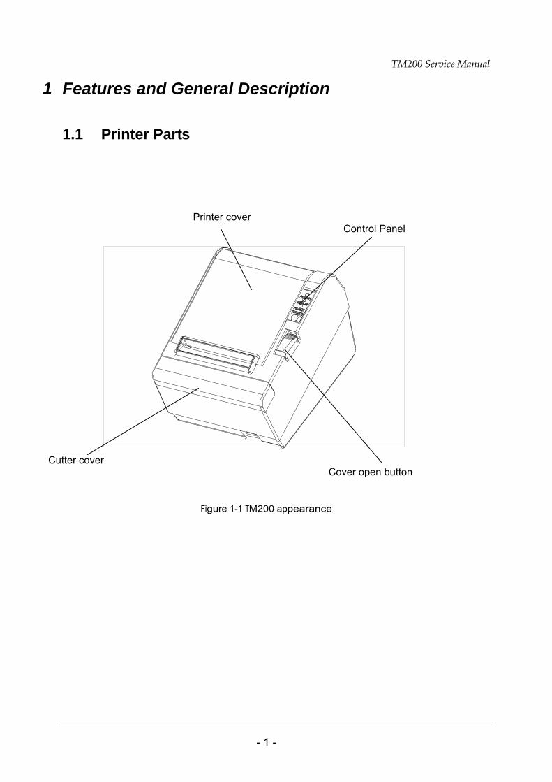
1.1 Printer Parts
Printer cover
Control Panel
Cutter cover Cover open button
Figure 1-1 TM200 appearance
TM200 Service Manual
- 2 -
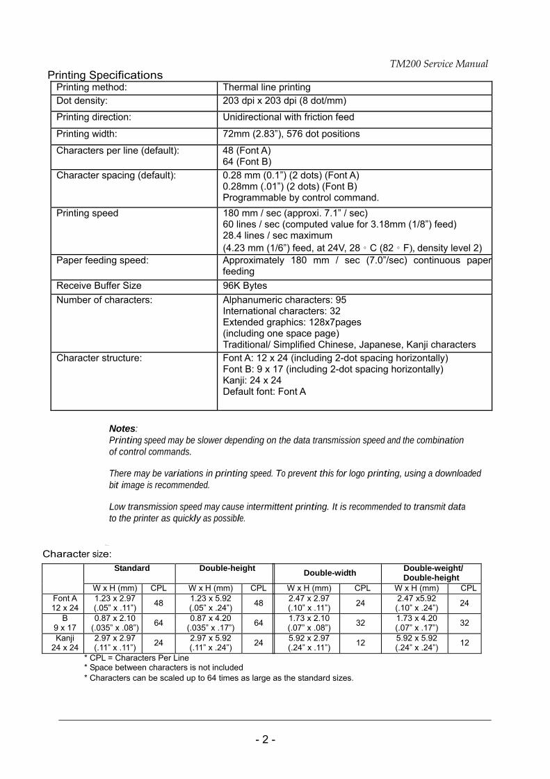
Printing Specifications Printing method: Thermal line printing Dot density: 203 dpi x 203 dpi (8 dot/mm)
Printing direction: Unidirectional with friction feed
Printing width: 72mm (2.83”), 576 dot positions
Characters per line (default): 48 (Font A) 64 (Font B)
Character spacing (default): 0.28 mm (0.1”) (2 dots) (Font A) 0.28mm (.01”) (2 dots) (Font B) Programmable by control command.
Printing speed 180 mm / sec (approxi. 7.1” / sec) 60 lines / sec (computed value for 3.18mm (1/8”) feed) 28.4 lines / sec maximum (4.23 mm (1/6”) feed, at 24V, 28。C (82。F), density level 2)
Paper feeding speed: Approximately 180 mm / sec (7.0”/sec) continuous paper feeding
Receive Buffer Size 96K Bytes Number of characters: Alphanumeric characters: 95
International characters: 32 Extended graphics: 128x7pages (including one space page) Traditional/ Simplified Chinese, Japanese, Kanji characters
Character structure: Font A: 12 x 24 (including 2-dot spacing horizontally) Font B: 9 x 17 (including 2-dot spacing horizontally) Kanji: 24 x 24 Default font: Font A
Notes: Printing speed may be slower depending on the data transmission speed and the combination of control commands.
There may be variations in printing speed. To prevent this for logo printing, using a downloaded bit image is recommended.
Low transmission speed may cause intermittent printing. It is recommended to transmit data to the printer as quickly as possible.
Character size:
* CPL = Characters Per Line * Space between characters is not included * Characters can be scaled up to 64 times as large as the standard sizes.
Double-width Double-weight/ Double-height
W x H (mm) CPL W x H (mm) CPL2.47 x 2.97 (.10” x .11”) 24 2.47 x5.92
(.10” x .24”) 24
1.73 x 2.10 (.07” x .08”) 32 1.73 x 4.20
(.07” x .17”) 32
5.92 x 2.97 (.24” x .11”) 12 5.92 x 5.92
(.24” x .24”) 12
Standard
Double-height
W x H (mm) CPL W x H (mm) CPLFont A 12 x 24
1.23 x 2.97 (.05” x .11”) 48 1.23 x 5.92
(.05” x .24”) 48
B 9 x 17
0.87 x 2.10 (.035” x .08”) 64 0.87 x 4.20
(.035” x .17”) 64
Kanji 24 x 24
2.97 x 2.97 (.11” x .11”) 24 2.97 x 5.92
(.11” x .24”) 24
TM200 Service Manual
- 3 -
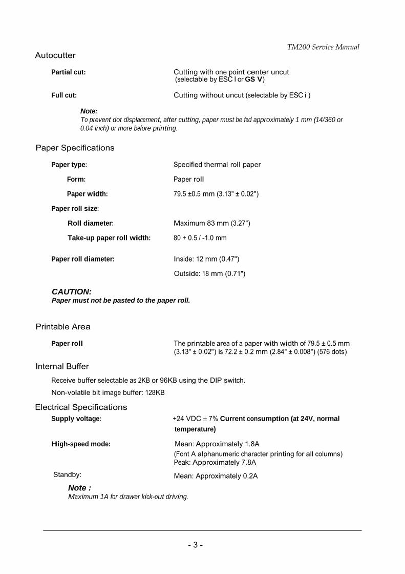
Autocutter
Partial cut: Cutting with one point center uncut (selectable by ESC I or GS V)
Full cut: Cutting without uncut (selectable by ESC i )
Note: To prevent dot displacement, after cutting, paper must be fed approximately 1 mm (14/360 or 0.04 inch) or more before printing.
Paper Specifications
Paper type: Specified thermal roll paper
Form: Paper roll
Paper width: 79.5 ±0.5 mm (3.13" ± 0.02")
Paper roll size:
Roll diameter: Maximum 83 mm (3.27")
Take-up paper roll width: 80 + 0.5 / -1.0 mm
Paper roll diameter: Inside: 12 mm (0.47")
Outside: 18 mm (0.71")
CAUTION: Paper must not be pasted to the paper roll.
Printable Area
Paper roll The printable area of a paper with width of 79.5 ± 0.5 mm
(3.13" ± 0.02") is 72.2 ± 0.2 mm (2.84" ± 0.008") (576 dots) Internal Buffer
Receive buffer selectable as 2KB or 96KB using the DIP switch.
Non-volatile bit image buffer: 128KB
Electrical Specifications
Supply voltage: +24 VDC ± 7% Current consumption (at 24V, normal temperature)
High-speed mode: Mean: Approximately 1.8A (Font A alphanumeric character printing for all columns) Peak: Approximately 7.8A
Standby:
Mean: Approximately 0.2A
Note : Maximum 1A for drawer kick-out driving.
TM200 Service Manual
- 4 -
EMI and Safety Standards Applied
These standards are only valid for products which bear a mark or statement on the main unit.
Europe: CE marking: Directive: 89/336/EEC
EN55022:1998 Class A EN6100-3-3:1995+A1:2001 EN55024:1998, including
IEC61000-4-2, IEC61000-4-3, IEC61000-4-4, IEC61000-4-5, IEC61000-4-6, IEC61000-4-8,
Safety standards: EN60950
North America: EMI: FCC Class A
Safety standards: UL1950/CSA C22.2 No.950
Oceania: EMI: AS/NZS3548
Conditions of acceptability
1. This component has been judged on the basis of the required spacing in the Standard
for Information Technology Equipment, including Electrical Business Equipment, UL 1950 and CSA22.2 No. 950. sub-clause 2.9, which would cover the component itself if submitted for Listing.
2. The terminals and connectors have not been evaluated for field wiring.
Reliability
Life: Mechanism: 15,000,000 lines
Thermal head: 100 million pulses, 50 Km
Autocutter: 1,200,000 cuts
(End of life is defined to have been reached when it reaches the beginning of the wear out period.)
MTBF: 360,000 hours
(Failure is defined as a random failure occurring during the time of the random failure period.)
MCBF: 52,000,000 lines
(This is an average failure interval based on failures relating to wear out and random failures up to the life of 15 million lines.)
External Dimensions and Weight:
Height: Approximately 138.7 mm (5.46")
Width: Approximately 146.5 mm (5.77")
Depth: Approximately 195 mm (7.68")
Weight: Approximately 1.4 kg (3.08 lb) (except for the paper roll)

TM200 Service Manual
- 5 -
Environmental Conditions
Temperature:
Operating: 5 to 45℃ (41 to 113℉) Storage: –10 to 50℃ (14 to 122℉) (except for paper)
Humidity:
Operating: 10 to 90% RH Storage: 10 to 90% RH (except for paper)
TM200 Service Manual
- 6 -
1.2 Major Component Specifications
TM200 Printer Mechanism
Paper Feed Motor Type: 4-phase, 48-polarity, PM-type stepping motor Drive voltage: 24 VDC ± 10% Winding resistance: 11.5 ± 10% at 25° C (77° F), per phase
Print Head Unit
Dot number: 576 dots Dot density: 0.125 mm/dot (203 DPI) Resistance: Average 600 ± 4.6%
Paper-end Sensor Reflection type photo sensor
Paper Roll Near-end Sensor Reflection type photo sensor
Autocutter Unit
Type: DC brush motor Cutter motor voltage: 24 VDC ± 7%
Current consumption: 800 mA peak (at starting, low temperature)
70 mA average (room temperature)
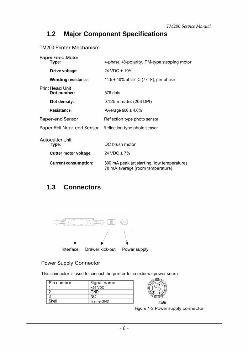
1.3 Connectors
Interface Drawer kick-out Power supply
Power Supply Connector This connector is used to connect the printer to an external power source.
Figure 1-2 Power supply connector
Pin number Signal name1 +24 VDC 2 GND 3 NC Shell Frame GND
TM200 Service Manual
- 7 -
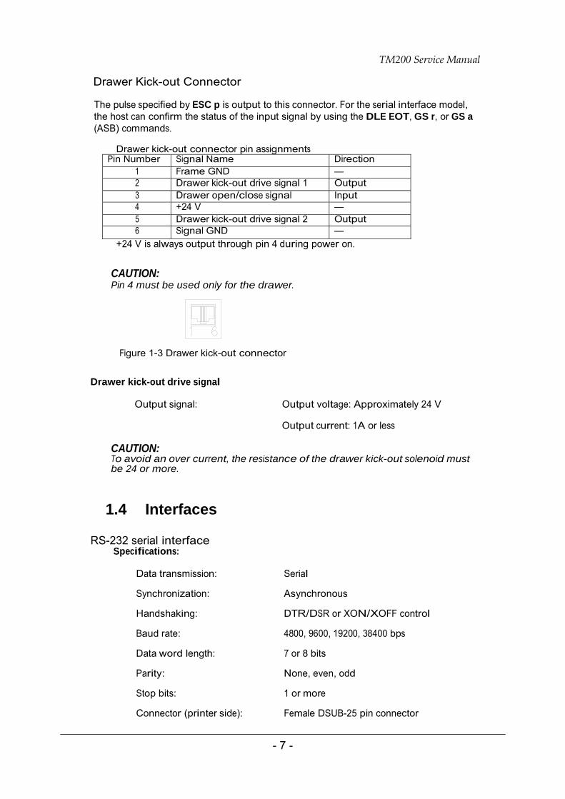
Drawer Kick-out Connector
The pulse specified by ESC p is output to this connector. For the serial interface model, the host can confirm the status of the input signal by using the DLE EOT, GS r, or GS a (ASB) commands.
Drawer kick-out connector pin assignments
Pin Number Signal Name Direction 1 Frame GND — 2 Drawer kick-out drive signal 1 Output 3 Drawer open/close signal Input 4 +24 V — 5 Drawer kick-out drive signal 2 Output 6 Signal GND —
+24 V is always output through pin 4 during power on.
CAUTION: Pin 4 must be used only for the drawer.
Figure 1-3 Drawer kick-out connector Drawer kick-out drive signal
Output signal: Output voltage: Approximately 24 V
Output current: 1A or less
CAUTION: To avoid an over current, the resistance of the drawer kick-out solenoid must be 24 or more.
1.4 Interfaces
RS-232 serial interface Specifications:
Data transmission: Serial Synchronization: Asynchronous Handshaking: DTR/DSR or XON/XOFF control Baud rate: 4800, 9600, 19200, 38400 bps Data word length: 7 or 8 bits Parity: None, even, odd Stop bits: 1 or more Connector (printer side): Female DSUB-25 pin connector
TM200 Service Manual
- 8 -
Note: The handshaking, data word length, baud rate, and parity depend on the DIP switch settings. Data transmitted from the printer has 1 stop bit (fixed)
Switching between online and offline
The printer does not have an online/offline switch. The printer goes offline:
When the cover is open
When an error has occurred
When the printer stops printing due to a paper-end(in cases when an
empty paper supply is detected by either paper roll end detector or the paper roll near- end detector with a printing halt feature using ESC c 4)
Interface connector terminal assignments and signal functions are described in the table below. TM200 serial printer status and signals:
Pin number Signal name Signal direction
Function
1 FG --- Frame ground 2 TXD Output Transmit data 3 RXD Input Receive data 4 RTS Output Same as DTR signal (Pin 20)
This signal indicates whether the host computer can receive data. SPACE indicates that the host computer can receive data, and MARK indicates that the host computer cannot receive data. When DTR/DSR control is selected, the printer transmits data after confirming this signal (except when transmitting data by DLE EOT, and GS a).
6 DSR Input
When XON/XOFF control is selected, the printer does not check this signal.
7 SG --- Signal ground
TM200 Service Manual
- 9 -
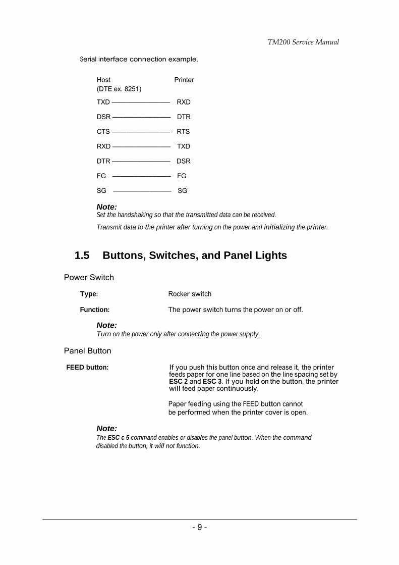
Serial interface connection example.
Host Printer (DTE ex. 8251)
TXD –––––––––––––––– RXD
DSR –––––––––––––––– DTR
CTS –––––––––––––––– RTS
RXD –––––––––––––––– TXD
DTR –––––––––––––––– DSR
FG –––––––––––––––– FG
SG –––––––––––––––– SG
Note: Set the handshaking so that the transmitted data can be received.
Transmit data to the printer after turning on the power and initializing the printer.
1.5 Buttons, Switches, and Panel Lights
Power Switch
Type: Rocker switch
Function: The power switch turns the power on or off.
Note: Turn on the power only after connecting the power supply.
Panel Button
FEED button: If you push this button once and release it, the printer
feeds paper for one line based on the line spacing set by ESC 2 and ESC 3. If you hold on the button, the printer will feed paper continuously.
Paper feeding using the FEED button cannot be performed when the printer cover is open.
Note: The ESC c 5 command enables or disables the panel button. When the command disabled the button, it will not function.
TM200 Service Manual
- 10 -
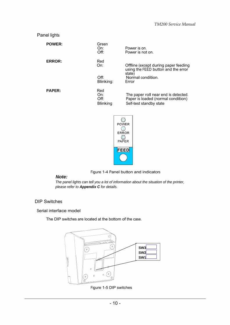
Panel lights
POWER: Green On: Power is on. Off: Power is not on.
ERROR: Red
On: Offline (except during paper feeding using the FEED button and the error state)
Off: Normal condition. Blinking: Error
PAPER: Red
On: The paper roll near end is detected. Off: Paper is loaded (normal condition) Blinking Self-test standby state
Figure 1-4 Panel button and indicators Note: The panel lights can tell you a lot of information about the situation of the printer, please refer to Appendix C for details.
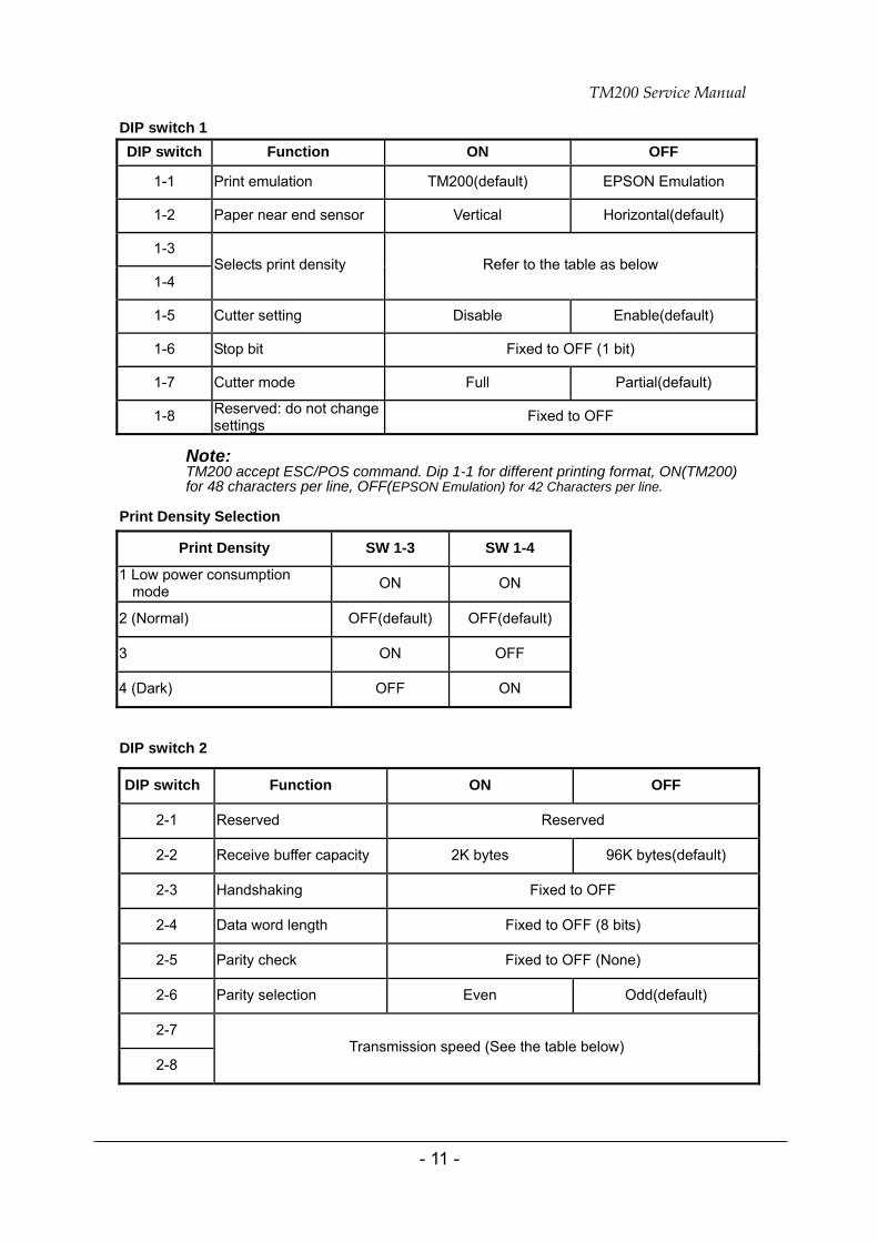
DIP Switches Serial interface model
The DIP switches are located at the bottom of the case.
Figure 1-5 DIP switches
SW3SW2SW1
TM200 Service Manual
- 11 -
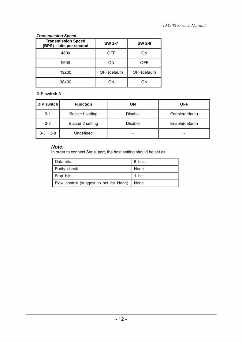
DIP switch 1
Note: TM200 accept ESC/POS command. Dip 1-1 for different printing format, ON(TM200) for 48 characters per line, OFF(EPSON Emulation) for 42 Characters per line.
Print Density Selection
DIP switch 2
DIP switch Function ON OFF
1-1 Print emulation TM200(default) EPSON Emulation
1-2 Paper near end sensor Vertical Horizontal(default)
1-3
1-4 Selects print density Refer to the table as below
1-5 Cutter setting Disable Enable(default)
1-6 Stop bit Fixed to OFF (1 bit)
1-7 Cutter mode Full Partial(default)
1-8 Reserved: do not change settings Fixed to OFF
Print Density SW 1-3 SW 1-4
1 Low power consumption mode ON ON
2 (Normal) OFF(default) OFF(default)
3 ON OFF
4 (Dark) OFF ON
DIP switch Function ON OFF
2-1 Reserved Reserved
2-2 Receive buffer capacity 2K bytes 96K bytes(default)
2-3 Handshaking Fixed to OFF
2-4 Data word length Fixed to OFF (8 bits)
2-5 Parity check Fixed to OFF (None)
2-6 Parity selection Even Odd(default)
2-7
2-8 Transmission speed (See the table below)
TM200 Service Manual
- 12 -
Transmission Speed
DIP switch 3
Note: In order to connect Serial port, the host setting should be set as:
Data bits 8 bits
Parity check None
Stop bits 1 bit
Flow control (suggest to set for None) None
Transmission Speed (BPS) – bits per second SW 2-7 SW 2-8
4800 OFF ON
9600 ON OFF
19200 OFF(default) OFF(default)
38400 ON ON
DIP switch Function ON OFF
3-1 Buzzer1 setting Disable Enable(default)
3-2 Buzzer 2 setting Disable Enable(default)
3-3 ~ 3-8 Undefined - -
TM200 Service Manual
- 13 -
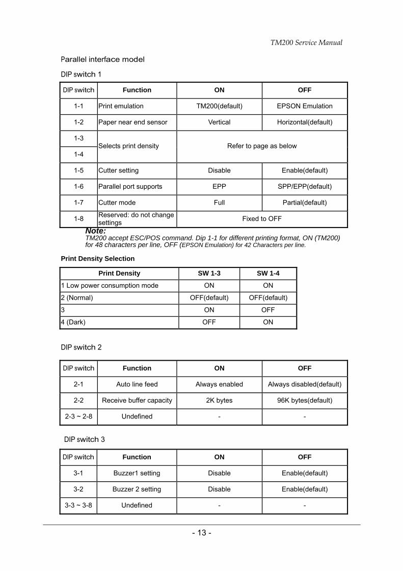
Parallel interface model DIP switch 1
Note: TM200 accept ESC/POS command. Dip 1-1 for different printing format, ON (TM200) for 48 characters per line, OFF (EPSON Emulation) for 42 Characters per line.
Print Density Selection
DIP switch 2
DIP switch 3
DIP switch Function ON OFF
1-1 Print emulation TM200(default) EPSON Emulation
1-2 Paper near end sensor Vertical Horizontal(default)
1-3
1-4 Selects print density Refer to page as below
1-5 Cutter setting Disable Enable(default)
1-6 Parallel port supports EPP SPP/EPP(default)
1-7 Cutter mode Full Partial(default)
1-8 Reserved: do not change settings Fixed to OFF
Print Density SW 1-3 SW 1-4
1 Low power consumption mode ON ON
2 (Normal) OFF(default) OFF(default)
3 ON OFF
4 (Dark) OFF ON
DIP switch Function ON OFF
2-1 Auto line feed Always enabled Always disabled(default)
2-2 Receive buffer capacity 2K bytes 96K bytes(default)
2-3 ~ 2-8 Undefined - -
DIP switch Function ON OFF
3-1 Buzzer1 setting Disable Enable(default)
3-2 Buzzer 2 setting Disable Enable(default)
3-3 ~ 3-8 Undefined - -
TM200 Service Manual
- 14 -
1.6 Self-test
The printer has a self-test function that checks the following:
Control circuit functions
Printer mechanisms
Print quality
Control software version
DIP switch settings.
NOTE: This test is independent of any other equipment or software.
Running the self test 1. Make sure the printer is turned off and the printer cover is closed properly. 2. Make sure a paper roll has been installed properly. 3. While holding down the FEED button, turn on the printer using the switch on the front
of the printer to begin the self test. The self test prints the printer settings, and then prints the following, cuts the paper, and pauses.
If you want to continue SELF-TEST
Please press the FEED button 4. Press the FEED button to continue printing. The printer prints a pattern using the
built-in character set. 5. The self test automatically ends and cuts the paper after printing the following.
*** completed *** Please re-start to exit SELF-TEST
TM200 Service Manual
- 15 -
1.7 Hexadecimal Dump
Hexadecimal Dump Function
This function prints the data transmitted from the host computer in hexadecimal numbers and in their corresponding characters.
Performing a Hexadecimal Dump
To use the hex dump feature, follow these steps:
1. After you make sure that the printer is off, open the cover.
2. Hold down the FEED button while you turn on the printer.
3. Close the cover.
4. Run any software program that sends data to the printer. The printer prints
“Hexadecimal Dump” and then all the codes it receives in a two-column format. The first column contains the hexadecimal codes and the second column gives the ASCII characters that correspond to the codes.
Hexadecimal Dump 1B 21 00 1B 26 02 40 40 ← ! ← & ☻ @ @ 1B 25 01 1B 63 34 00 1B ←%☺← c 4 ← 41 42 43 44 45 43 47 48 ABCDEFGH
5. Close the cover and turn off the printer or reset it to turn off the hex dump
mode. (or to terminate hex dump, press FEED button three times, and when you see
*** completed *** the hex dump mode was turned off.
Note: Insufficient print data to fill the last line can be printed by setting the printer offline.
Ending hexadecimal dumping
Hexadecimal dumping ends by turning the power off or resetting the printer via the interface after printing has finished.
TM200 Service Manual
- 16 -
1.8 Paper Sensors
The printer has 2 paper sensors as follows:
Paper roll near-end sensor
The sensor detects a near-end of a paper roll. When the paper roll diameter becomes sufficiently small, the sensor detects a near-end of the paper roll and the PAPER indicator lights on.
Paper roll end sensor
This sensor detects whether paper is present or not. When the sensor detects a paper-end, the printer stops printing.
Note: After installing new paper roll, close the printer cover; then the printer restarts printing.
Cover Open Button
When the cover open button (located to the right of the cover) is pressed, the printer cover is opened. When the cover is closed, the cover open button is latched.
Note: Be sure to use the cover open button to open the printer cover. Do not open the cover during printing. Do not open the cover during the autocutter is operating; otherwise the mechanism may be damaged.
Cover Open Sensor
The cover open sensor monitors the printer cover. When the sensor detects a cover open during printing, the ERROR light blinks and the printer stops printing. The printer recovers when the cover is closed. When the sensor detects a cover open while the printer is in the standby status, the printer goes offline. The printer recovers when the cover is closed.
Note: Whether the cover is open or not does not affect the status reported by the paper roll end sensor.
1.9 Standard Accessories
Sample paper roll x 1 roll
User's Manual
Exclusive external power supply unit and power cord
Disc x 1 Communication printer cable
TM200 Service Manual
- 17 -
1.10 Options
Standard cable cover set (included wall mounting bracket)
Top waterproof cover
1.11 Consumables
Specified paper
Specified paper Roll paper: NTP080-80
Original paper: TF50KS-E Nippon Paper Industries Co., Ltd.
Packaged roll paper Original paper: PD160R Oji Paper Mfg. Co. Ltd.
In Japan: Nakagawa, Seisakujo
In North America: Nakagawa Mfg. (USA) Inc.
In Europe: Nakagawa Mfg. (Europe) GmbH
In Southeast Asia: N.A.K. Mfg. (Malaysia) SDN BHD
Note: The following paper can be used instead of the specified paper above.
Original paper: AF50KS-E Jujo Thermal Oy (Finland)
P350 (F380), P310 Kanzaki Specialty Papers, Inc. (U.S.A.)
PD190R Oji Paper Mfg. Co. Ltd.
Note: Do not use any paper other than these specified above. Otherwise, print head reliability and print quality are affected adversely.
1.12 External Power Supply Specifications
Input specifications
Rated input voltage 90 to 264 VAC
Rated frequency 50/60 Hz ± 3
Hz Rated input current Less than 100 V
A Power switch None Power LED None

TM200 Service Manual
- 18 -
Output specifications
Output voltage 24 VDC ± 5%
Rated output current 2.5 A
Rated output power Approximately 60 W
Output peak current 4.5 A (within 300 ms duty 1/6)
TM200 Service Manual
- 19 -
2 Mechanisms and Operation
2.1 Component Connections
This printer is made up of the following major components:
TM200 printer mechanism (switch circuit board assembly)
I/F circuit board assembly
Main circuit board unit
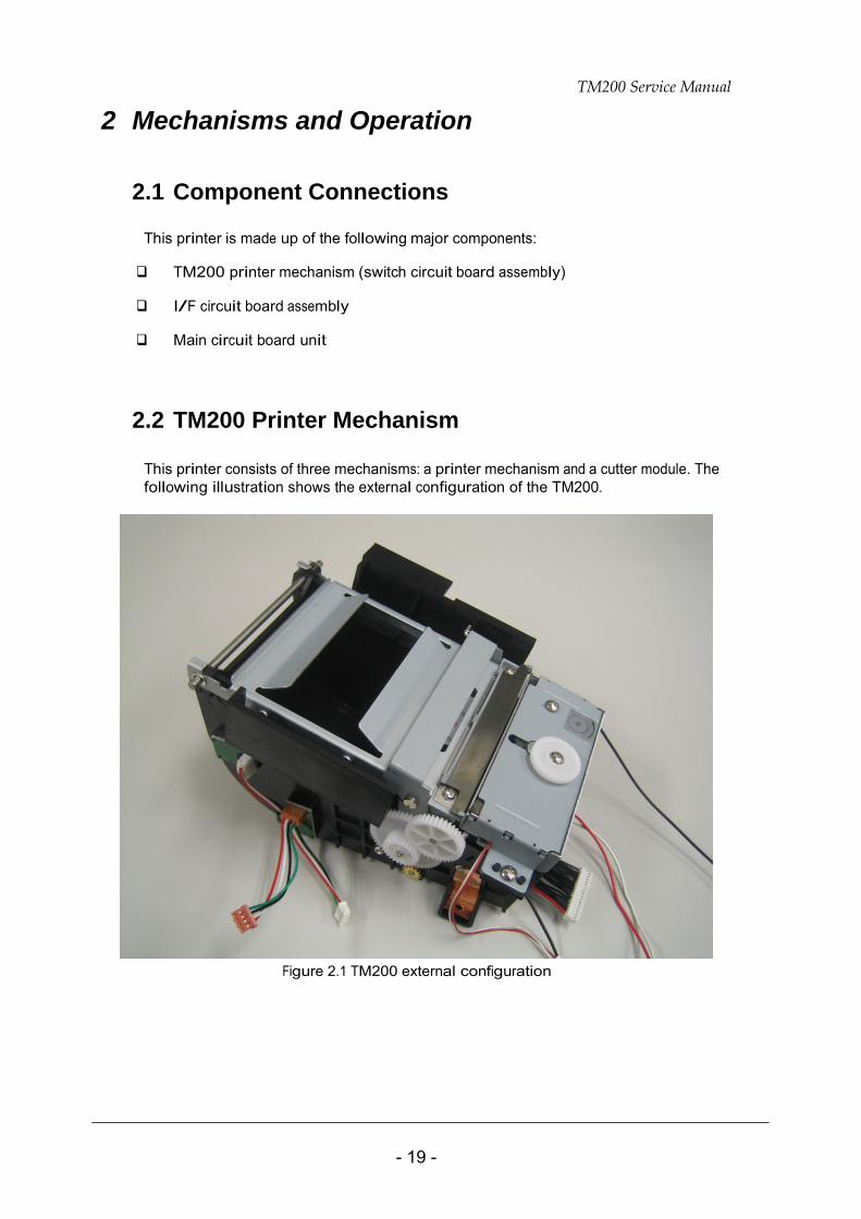
2.2 TM200 Printer Mechanism
This printer consists of three mechanisms: a printer mechanism and a cutter module. The following illustration shows the external configuration of the TM200.
Figure 2.1 TM200 external configuration
TM200 Service Manual
- 20 -
Printer Mechanism Thermal head Module
The thermal head is designed so its heating element is positioned where it comes into contact with the platen. The roll paper wrapped around the platen is kept in contact with the thermal head’s heating element at a prescribed pressure, and printing is performed when heat is generated by the heating element. Printing is performed according to the following steps:
1. The print signal sends a prescribed energizing pulse to the electrodes that
correspond to each dot to be printed.
2. Resistors at each electrode generate heat. 3. The heat energy generated by the resistors is transmitted to the roll paper surface
through the protective layer to the paper’s heat-sensitive layer, causing coloration of the paper.
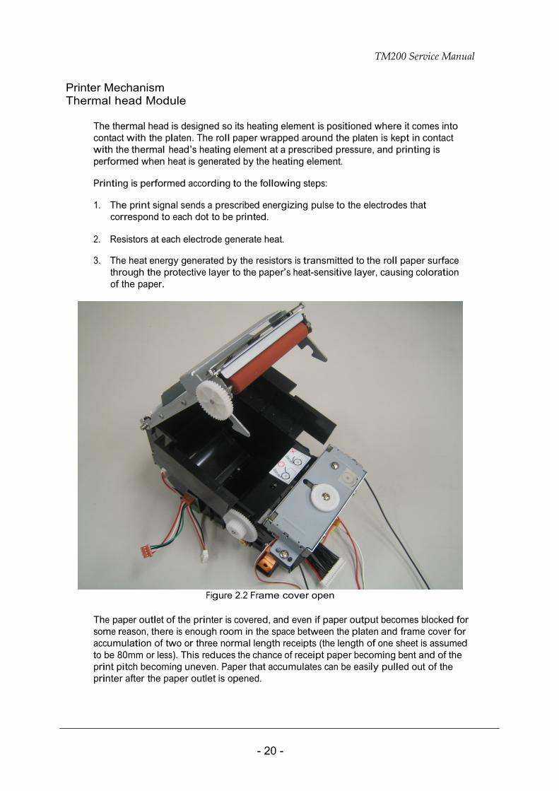
Figure 2.2 Frame cover open
The paper outlet of the printer is covered, and even if paper output becomes blocked for some reason, there is enough room in the space between the platen and frame cover for accumulation of two or three normal length receipts (the length of one sheet is assumed to be 80mm or less). This reduces the chance of receipt paper becoming bent and of the print pitch becoming uneven. Paper that accumulates can be easily pulled out of the printer after the paper outlet is opened.
TM200 Service Manual
- 21 -
Autocutter Module
This printer is equipped with an autocutter module for cutting of the roll paper and a manual cutter for manual cutting.
The autocutter has two opposing cutter blades that operate like a scissors to cut the paper. It is a separate cutter blade-type mechanism that does not require passage of the roll paper through an autocutter mechanism slit. Opening the frame cover causes the stationary blade to separate completely from the moving blade. The stationary blade is fixed to the frame cover, while the moving blade is attached to the main frame.
Autocutter operation
The frame cover can be closed while the movable blade is in the home position. Closing the frame cover causes the stationary blade to come into partial contact with the paper cutter frame, and the stationary blade and movable blade are brought into relative position.
Cutter blade knob
The movable blade is in the home position whenever cutter operation is not being performed. In addition to safety considerations, this enables a mechanism in which the frame cover cannot be opened or closed while the movable blade is not in the home position.
2.3 Main Circuit Board Unit
The main circuit board unit is made up of the following electrical circuits:
CPU and CPU peripheral logic circuits CPU RAM ROM Gate array Reset circuit
TM200 control circuits
Thermal head drive circuit Paper feed motor drive circuit Autocutter drive circuit Detector circuits
Control panel control circuits
Drawer kick control circuit
Power supply circuits
Filter circuits
+24V output circuit +5V output circuit
TM200 Service Manual
- 22 -
CPU peripheral logic circuits RAM (128K byte)
RAM is used for temporary storage of the following:
Data received from the interface (receive buffer)
Pattern data printed by the print head unit (printer buffer)
Data used for CPU routines (flags, pointers, etc.)
Flash memory (2M or 8M bits)
A printer control program and character generator data is written into flash memory. The control program controls basic printer operations, and all CPU control is performed in accordance with this program. Another flash memory works as a sub-memory for such items as expanding character generator data.
RS-232C interface specifications
Selection between two signals (pin 6 (DSR) or pin 25 (INIT)) is possible.
TM200 Control Circuit
Thermal head driver circuit
The print head of the receipt printer mechanism is a thermal type print head with 576 dots per line. All print head control is performed via a gate array. A driver is built into the print head, and sending of print signal DATA-IN, which is synchronized with the CLOCK signal, to the driver sets the print/non-print status of each dot. Data is confirmed by latch signal #LATCH. Print time control is performed by #STROBE1 and #STROBE2, while energizing time is controlled by the gate array.
Changes in head temperature causes fluctuation of the resistance value of the thermistor built into the head, which is output as temperature signal THERMISTOR.
Paper feed motor driver circuit
The paper feed motor is constant-current driven by a special-purpose IC. The energizing direction switching signals (PH1,PH2,PH3 and PH4) from the CPU. The special-purpose IC controls the paper feed motor in accordance with these signals using Q1, Q2, Q3, and Q4 signals.
Autocutter driver circuit
The autocutter driver use MOSFET to control DC motor.
Detector circuits
Paper end sensor circuit
The thermal printer mechanism is equipped with a paper end sensor, which is connected via switch circuit board assembly to the main circuit board unit. The paper end signal FP_Sensor is input to the DSP’s port.
Cover open sensor circuit
TM200 Service Manual
- 23 -
The cover open sensor is located next to the thermal printer mechanism, and it is connected via Door Sensor board assembly to the main circuit board unit. Detector signal INPUT_4 is input to the CPU.
Control Panel Control Circuit
This control panel is located on the mainboard. It has three LEDs (POWER, ERROR, PAPER) and one button (FEED). The POWER LED drives when +5V is supplied by the power circuit. The ERROR and PAPER LEDs are controlled by the CPU.
Drawer Kick Control Circuit
When signals KICK_OUT_X1 and KICK_OUT_X2 from CPU go active, it causes transistor array and outputting the drawer drive signal. The OPEN_CLOSE signal, which indicates whether or not the drawer is open, is input to the CPU, and this status can be obtained from the host interface.
Power Supply Circuit
The table as below shows supply voltage values and their applications.
Power supply voltage values and applications
Voltage Value Main Applications 1.8V Power supply for the CPU core 3.3V Power supply for the CPU I/O pins
Logic circuit power supply Interface board power supply Detector power supply
+5V (VCC)
Thermal head logic circuit power supply Printer mechanism power supply Paper feed motor Thermal head Autocutter
+24V
Drawer kick driver power supply
+24V Control Circuit
The +24V power supply is split between the printer power supply and +5V. Then split into 3.3V and 1.8V.
+5V Control Circuit
A +5V regulator circuit switches the input +24V power supply and converts it to +5V. The switching regulator IC switches the input +24V, and +5V voltage is output.
The RS-232 power supply is generated by a charge up circuit built into the RS-232 interface’s onboard driver.
TM200 Service Manual
- 24 -
2.4 I/F Circuit Board
This printer uses a TM series universal interface, which allows support of a variety of different interfaces by changing the interface board.
RS-232 Interface
IEEE 1284 Interface
USB Interface
Multi interface (Parallel and Serial)
2.5 Switch Circuit Board
Switch circuit board has the following built-in electrical circuits:
Paper FEED button
LED (POWER, ERROR, PAPER)
TM200 Service Manual
- 25 -
3 Handling, Maintenance, and Repairs
3.1 Handling
Transport Precautions
Take the following steps to protect the unit against vibration and impact whenever transporting it: CAUTION:
We recommend that each unit be packed individually in the boxes supplied by LABAU Technology Corp..
Remove the paper from the unit.
Make sure that the paper roll cover is securely closed.
Setup Precautions
Note: The cover of the unit is secured in place with tape. Remove the tape before using the unit.
Operational Precautions
Observing the following operational precautions protects the unit against damage.
CAUTION:
Connect the interface cable, power cable, and drawer cable to the applicable connectors of the unit. Do not use undue force when plugging cables into connectors.
Do not turn unit power off during normal operation. Be especially careful to avoid turning power off while a paper cut operation is being performed. Doing so can result in the cutter blade being exposed, which will make it impossible to open the paper roll cover.
Never pull out paper while the paper roll cover is open.
During normal operation, never open the cutter cover and rotate the cutter manual knob by hand. Doing so can cause the cutter blade to be exposed, making it impossible to open the paper roll cover.
The heating element of the printer mechanism’s thermal head and the driver IC are easily damaged. Never allow these components to come into contact with metal or other hard objects.
Never touch the printer mechanism’s (thermal head’s) heating element with your hand. Doing so can soil the heating element and affect proper operation.
The head and motor areas are very hot during and immediately after printing. Do not touch components in these areas directly with your hand.
TM200 Service Manual
- 26 -
Paper Precautions
CAUTION: Be sure to use only paper that conforms with the specifications in the preceding section of this manual. Thermal paper that includes Na, K, or C1 ions can affect proper operation of the thermal head’s heating element.
Thermal paper starts to color at around 70°C. Take care to protect unused and printed thermal paper against the effects of heat, light, and humidity, which can cause the paper to color and characters on the paper to fade.
Take the paper roll out of the printer when you will not use the printer for a long time in a high temperature and humidity environment.
Do not use this unit to print on label paper.
Loading paper roll
Note: Be sure to use paper rolls that meet the specifications. Do not use paper rolls that have the paper glued to the core because the printer cannot detect the paper end correctly.
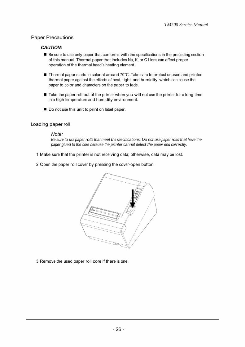
1. Make sure that the printer is not receiving data; otherwise, data may be lost. 2. Open the paper roll cover by pressing the cover-open button.
3. Remove the used paper roll core if there is one.
TM200 Service Manual
- 27 -
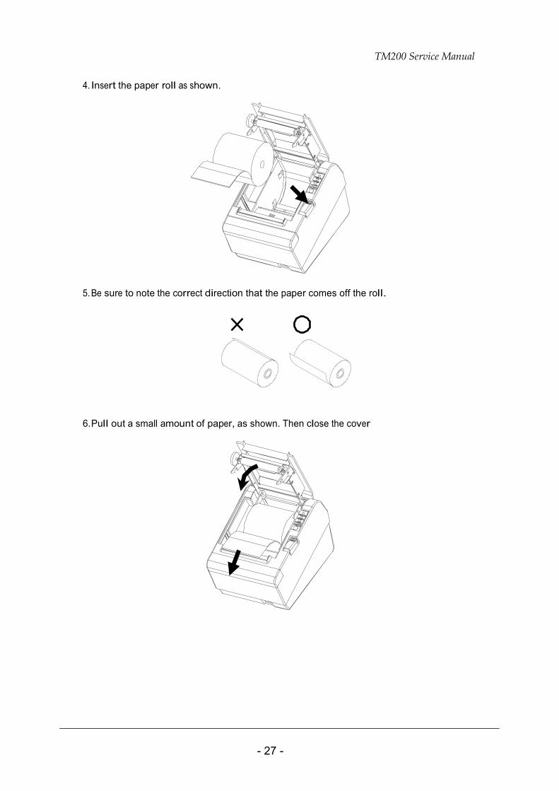
4. Insert the paper roll as shown.
5. Be sure to note the correct direction that the paper comes off the roll.
6. Pull out a small amount of paper, as shown. Then close the cover
TM200 Service Manual
- 28 -
3.2 Problem Solving
Errors
See Chapter 4, Error Types and Processing. Paper roll cover does not open (paper roll cover button does not work)
1. Turn the printer off and press the cover open button to open the cover.
2. Remove the jammed paper and put the roll back in the printer and close the cover. (Take care not to touch the print head.)
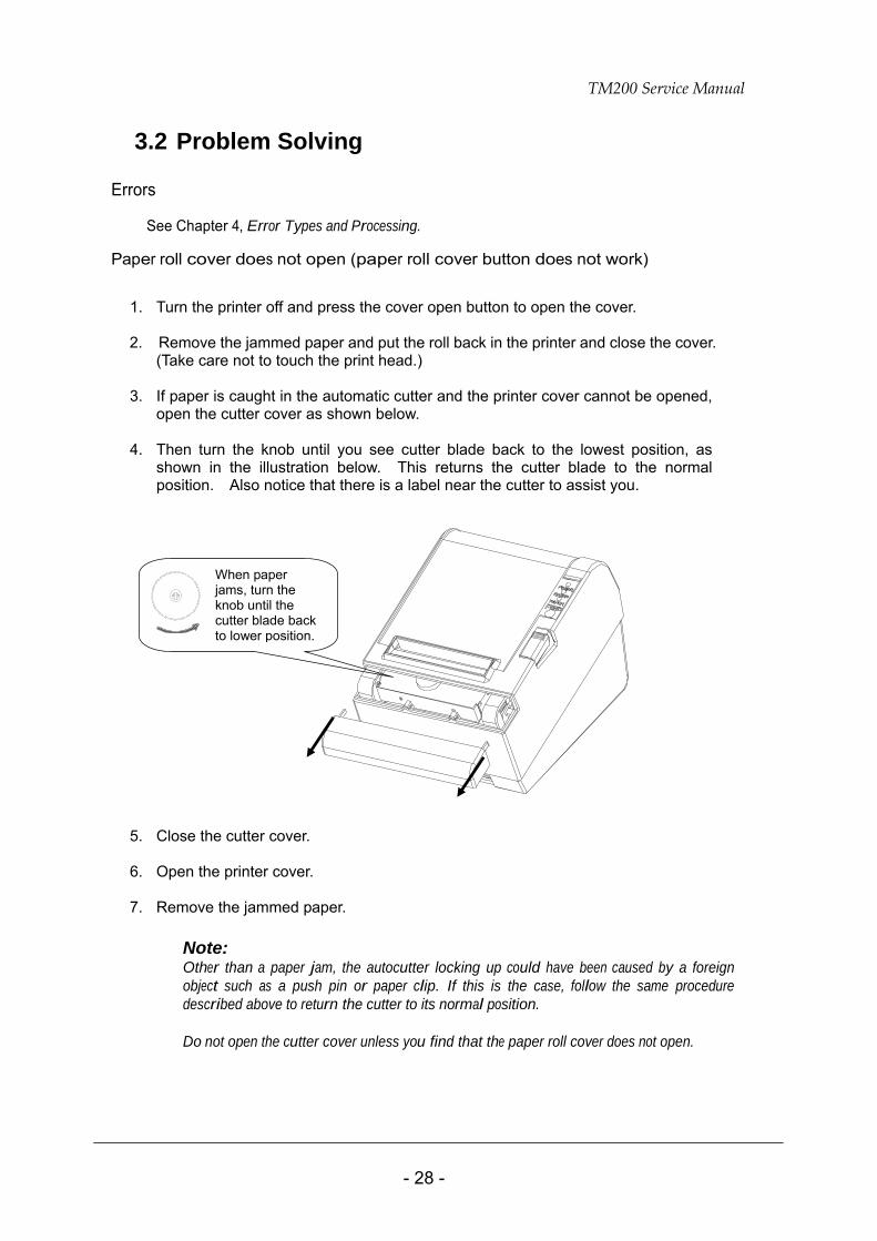
3. If paper is caught in the automatic cutter and the printer cover cannot be opened,
open the cutter cover as shown below.
4. Then turn the knob until you see cutter blade back to the lowest position, as shown in the illustration below. This returns the cutter blade to the normal position. Also notice that there is a label near the cutter to assist you.
5. Close the cutter cover.
6. Open the printer cover.
7. Remove the jammed paper.
Note: Other than a paper jam, the autocutter locking up could have been caused by a foreign object such as a push pin or paper clip. If this is the case, follow the same procedure described above to return the cutter to its normal position.
Do not open the cutter cover unless you find that the paper roll cover does not open.
When paper jams, turn the knob until the cutter blade back to lower position.
TM200 Service Manual
- 29 -
3.3 Clearing Paper Jams
CAUTION: Take care not to let metal objects come into contact with the thermal head. Metal can damage the head.
Do not touch the thermal head or radiation plate. Printing can cause them to become very hot.
1. Open the paper roll cover.
Note: See the previous section for steps to take if the paper roll cover does not open.
2. Next, turn power off.
3. Grasp the leading end of the receipt paper and pull the jammed paper.
Note: Be sure to remove all of the paper. Leaving part of the paper in the unit can cause the sensor to malfunction.
4. Correct the problem that caused the paper jam and reload the paper roll into the unit.
Note: See the section “Loading paper roll” for details on how to load paper roll.
TM200 Service Manual
- 30 -
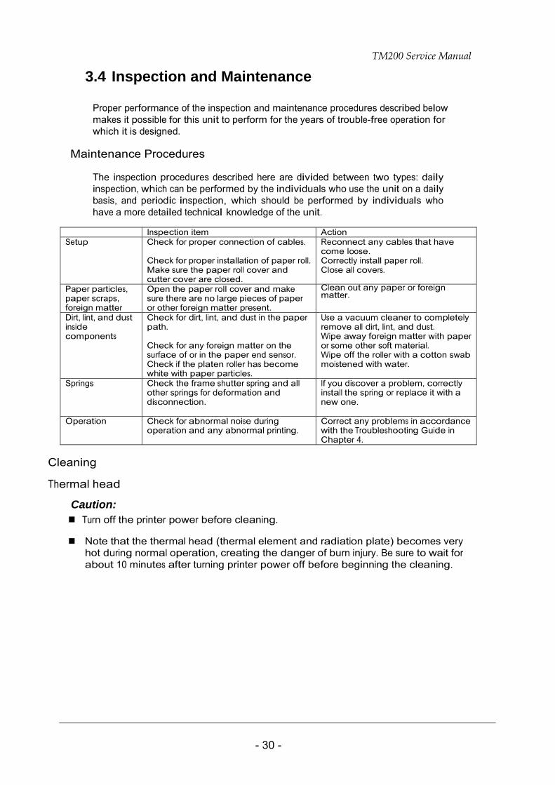
3.4 Inspection and Maintenance
Proper performance of the inspection and maintenance procedures described below makes it possible for this unit to perform for the years of trouble-free operation for which it is designed.
Maintenance Procedures
The inspection procedures described here are divided between two types: daily inspection, which can be performed by the individuals who use the unit on a daily basis, and periodic inspection, which should be performed by individuals who have a more detailed technical knowledge of the unit.
Inspection item Action Setup Check for proper connection of cables.
Check for proper installation of paper roll.Make sure the paper roll cover and cutter cover are closed.
Reconnect any cables that have come loose. Correctly install paper roll. Close all covers.
Paper particles, paper scraps, foreign matter
Open the paper roll cover and make sure there are no large pieces of paper or other foreign matter present.
Clean out any paper or foreign matter.
Dirt, lint, and dust inside components
Check for dirt, lint, and dust in the paper path. Check for any foreign matter on the surface of or in the paper end sensor. Check if the platen roller has become white with paper particles.
Use a vacuum cleaner to completely remove all dirt, lint, and dust. Wipe away foreign matter with paper or some other soft material. Wipe off the roller with a cotton swab moistened with water.
Springs Check the frame shutter spring and all other springs for deformation and disconnection.
If you discover a problem, correctly install the spring or replace it with a new one.
Operation Check for abnormal noise during operation and any abnormal printing.
Correct any problems in accordance with the Troubleshooting Guide in Chapter 4.
Cleaning
Thermal head
Caution: Turn off the printer power before cleaning.
Note that the thermal head (thermal element and radiation plate) becomes very
hot during normal operation, creating the danger of burn injury. Be sure to wait for about 10 minutes after turning printer power off before beginning the cleaning.
TM200 Service Manual
- 31 -
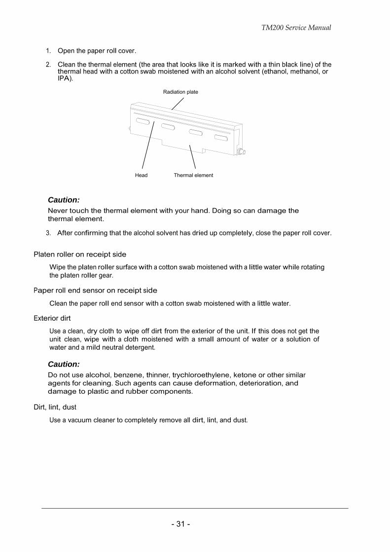
1. Open the paper roll cover.
2. Clean the thermal element (the area that looks like it is marked with a thin black line) of the thermal head with a cotton swab moistened with an alcohol solvent (ethanol, methanol, or IPA).
Radiation plate
Head Thermal element
Caution: Never touch the thermal element with your hand. Doing so can damage the thermal element.
3. After confirming that the alcohol solvent has dried up completely, close the paper roll cover.
Platen roller on receipt side
Wipe the platen roller surface with a cotton swab moistened with a little water while rotating the platen roller gear.
Paper roll end sensor on receipt side
Clean the paper roll end sensor with a cotton swab moistened with a little water.
Exterior dirt
Use a clean, dry cloth to wipe off dirt from the exterior of the unit. If this does not get the unit clean, wipe with a cloth moistened with a small amount of water or a solution of water and a mild neutral detergent. Caution: Do not use alcohol, benzene, thinner, trychloroethylene, ketone or other similar agents for cleaning. Such agents can cause deformation, deterioration, and damage to plastic and rubber components.
Dirt, lint, dust
Use a vacuum cleaner to completely remove all dirt, lint, and dust.
TM200 Service Manual
- 32 -
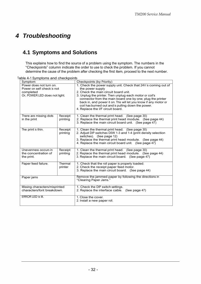
4 Troubleshooting
4.1 Symptoms and Solutions
This explains how to find the source of a problem using the symptom. The numbers in the “Checkpoints” column indicate the order to use to check the problem. If you cannot determine the cause of the problem after checking the first item, proceed to the next number.
Table 4-1 Symptoms and checkpoints
Symptom Checkpoints (by Priority) Power does not turn on. Power on self check is not completed Or, POWER LED does not light.
1. Check the power supply unit. Check that 24V is coming out of the power supply
2. Check the main circuit board unit. 3. Unplug the printer. Then unplug each motor or coil's
connector from the main board one by one; plug the printer back in, and power it on. This will let you know if any motor or coil has burned out and is pulling down the power.
4. Replace the I/F circuit board.
There are missing dots in the print
Receipt printing
1. Clean the thermal print head. (See page 30) 2. Replace the thermal print head module. (See page 44) 3. Replace the main circuit board unit. (See page 47)
The print is thin. Receipt printing
1. Clean the thermal print head. (See page 30) 2. Adjust DIP switches DSW 1-3 and 1-4 (print density selection
switches). (See page 12) 3. Replace the thermal print head module. (See page 44) 4. Replace the main circuit board unit. (See page 47)
Unevenness occurs in the concentration of the print.
Receipt printing
1. Clean the thermal print head. (See page 30) 2. Replace the thermal print head module. (See page 44) 3. Replace the main circuit board. (See page 47)
Paper feed failure. Thermal printer
1. Check that the roll paper is properly loaded. 2. Check the receipt paper feed motor. 3. Replace the main circuit board. (See page 44)
Paper jams Remove the jammed paper by following the directions in “Clearing Paper Jams.”
Missing characters/misprinted characters/font breakdown.
1. Check the DIP switch settings. 2. Replace the interface cable. (See page 47)
ERROR LED is lit.
1. Close the cover. 2. Install a new paper roll.
TM200 Service Manual
- 33 -
4.2 Error Types and Processing
Printer Operation when an Error Occurs
The printer executes the following operations upon detecting an error.
Stops all printer operations.
Flashes the ERROR LED.
Data Receive Error (only with the serial interface model)
If one of the following errors occurs during serial interface communications, the printer ignores the data
Parity error
Framing error
Overrun error
TM200 Service Manual
- 34 -
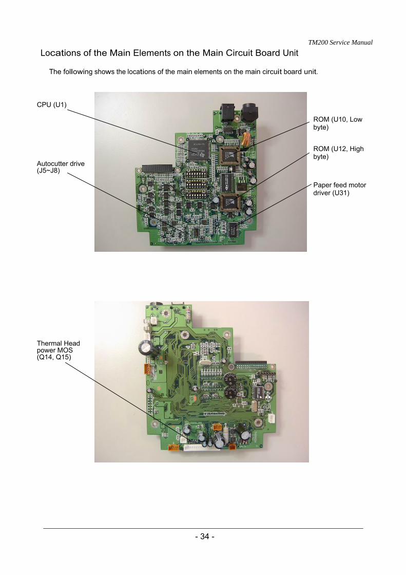
Locations of the Main Elements on the Main Circuit Board Unit
The following shows the locations of the main elements on the main circuit board unit.
CPU (U1)
ROM (U10, Low byte)
ROM (U12, High byte)
Autocutter drive (J5~J8)
Paper feed motor driver (U31)
Thermal Head power MOS (Q14, Q15)
TM200 Service Manual
- 35 -
5 Disassembly, Assembly, and Adjustment
5.1 Before Starting disassembly, assembly, and adjustment Be sure to observe the following important points whenever performing disassembly, assembly, or adjustment.
Caution: Disconnect the power supply unit from the printer before beginning work. Current continues to flow through internal circuitry even when the printer’s power switch is turned off. Performing work without disconnecting the power supply can cause serious damage to the printer.
Disconnect all peripherals connected to the printer before beginning work.
Perform all disassembly in accordance with the procedures in this manual. Incorrect disassembly can cause serious damage to the printer.
Never touch an FPC or its connectors with your fingers. Getting dirt on the FPC or its connectors can result in improper connection.
5.2 Using this Manual
This section explains a number of general conventions used in this manual. Titles
The titles that appear inside the sections of this manual describe the assembly and disassembly of major parts and blocks. Not all of the parts (service parts) are indicated as titles.
Disassembly, Assembly, and Adjustment Procedures
The procedures in this manual are arranged so the entire printer is disassembled when performed from beginning to end.
Disassembly of some parts and blocks may be impossible unless performed in accordance with the procedures described in this manual.
Perform the procedures in this manual in reverse to assemble the printer.
TM200 Service Manual
- 36 -
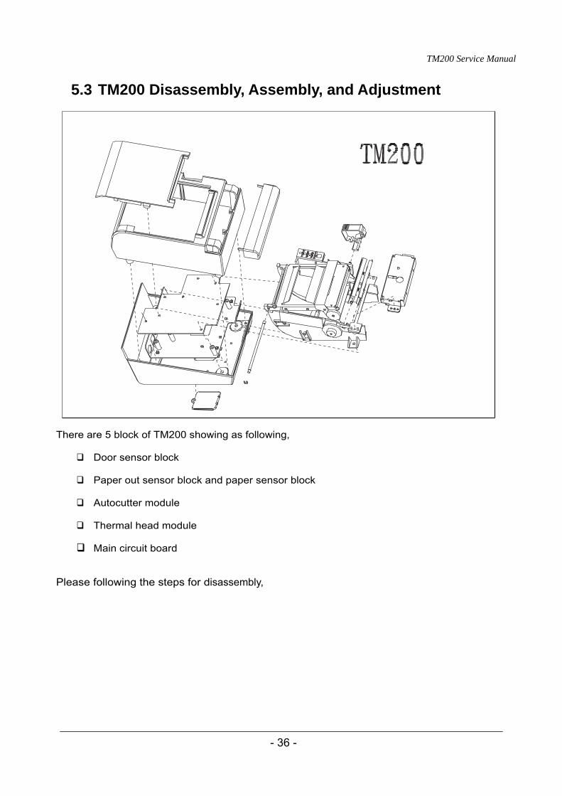
5.3 TM200 Disassembly, Assembly, and Adjustment
There are 5 block of TM200 showing as following,
Door sensor block
Paper out sensor block and paper sensor block
Autocutter module
Thermal head module
Main circuit board Please following the steps for disassembly,
TM200 Service Manual
- 37 -
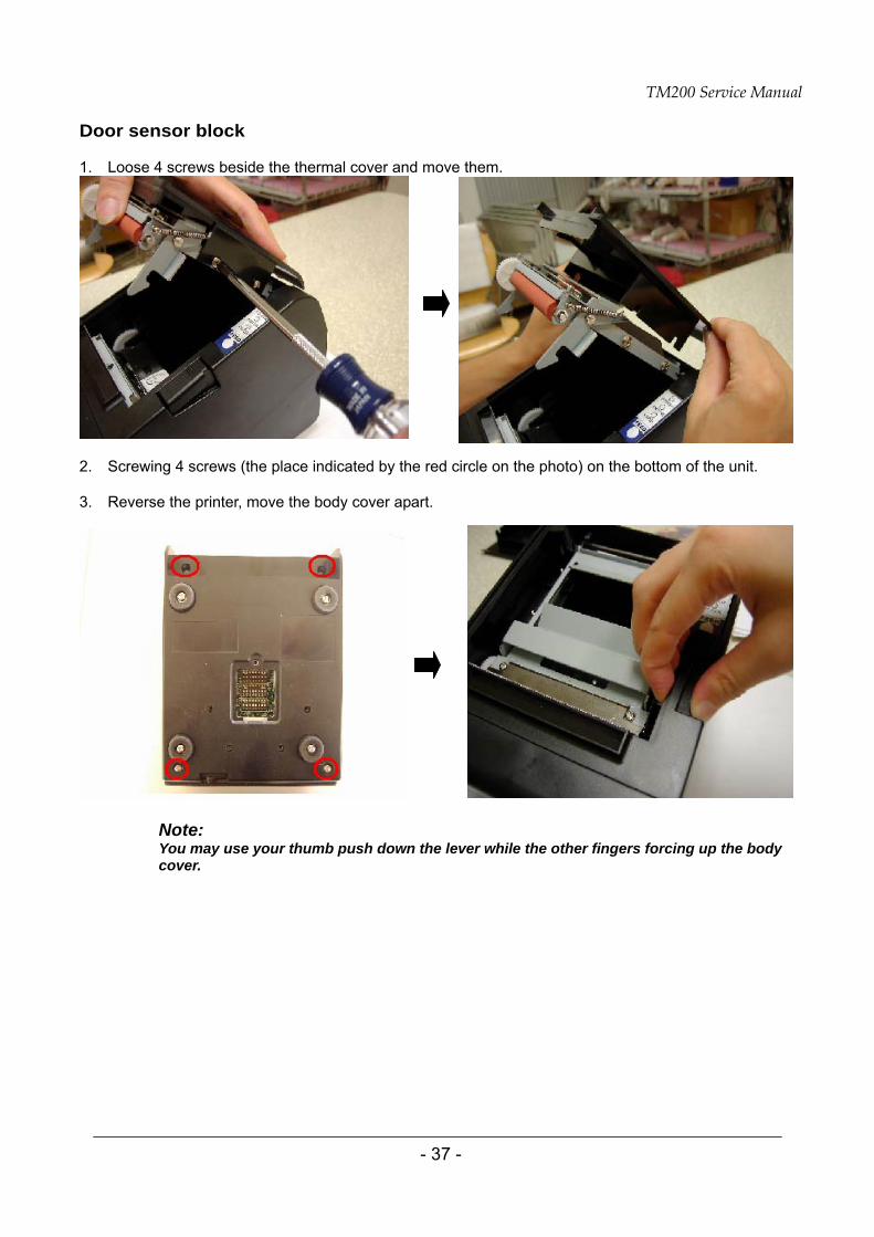
Door sensor block
1. Loose 4 screws beside the thermal cover and move them.
2. Screwing 4 screws (the place indicated by the red circle on the photo) on the bottom of the unit. 3. Reverse the printer, move the body cover apart.
Note: You may use your thumb push down the lever while the other fingers forcing up the body cover.
TM200 Service Manual
- 38 -
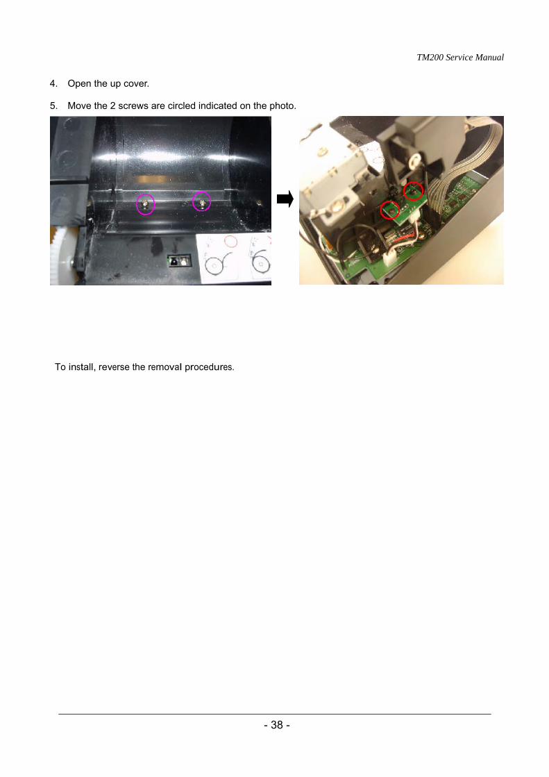
4. Open the up cover. 5. Move the 2 screws are circled indicated on the photo.
To install, reverse the removal procedures.
TM200 Service Manual
- 39 -
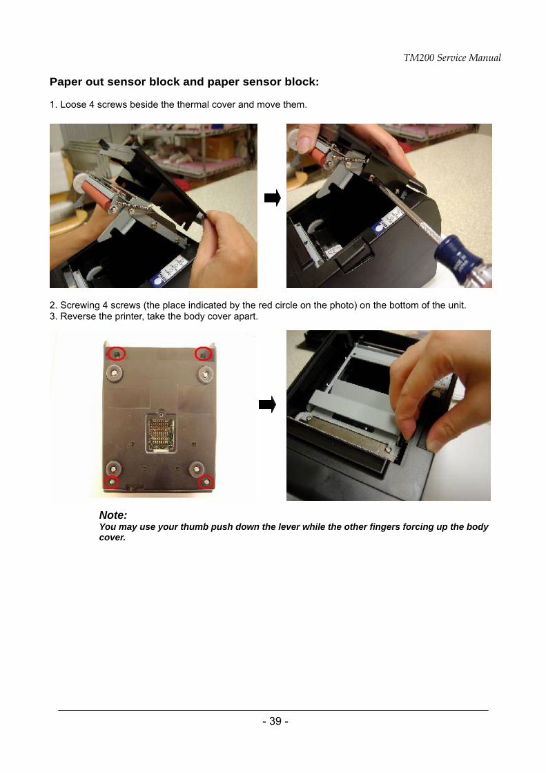
Paper out sensor block and paper sensor block:
1. Loose 4 screws beside the thermal cover and move them.
2. Screwing 4 screws (the place indicated by the red circle on the photo) on the bottom of the unit. 3. Reverse the printer, take the body cover apart.
Note: You may use your thumb push down the lever while the other fingers forcing up the body cover.
TM200 Service Manual
- 40 -
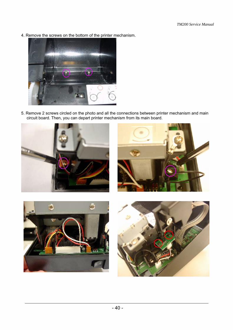
4. Remove the screws on the bottom of the printer mechanism.
5. Remove 2 screws circled on the photo and all the connections between printer mechanism and main circuit board. Then, you can depart printer mechanism from its main board.
TM200 Service Manual
- 41 -
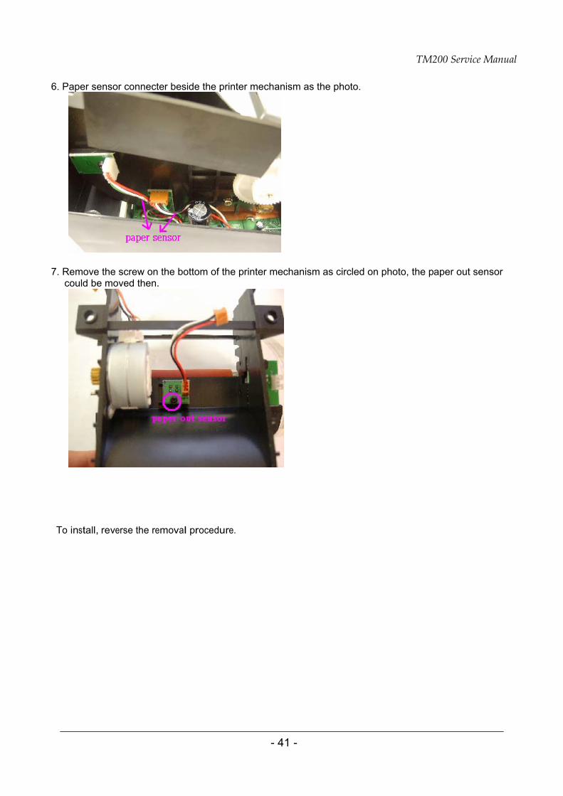
6. Paper sensor connecter beside the printer mechanism as the photo.
7. Remove the screw on the bottom of the printer mechanism as circled on photo, the paper out sensor could be moved then.
To install, reverse the removal procedure.
TM200 Service Manual
- 42 -
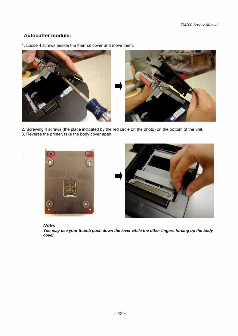
Autocutter module:
1. Loose 4 screws beside the thermal cover and move them.
2. Screwing 4 screws (the place indicated by the red circle on the photo) on the bottom of the unit. 3. Reverse the printer, take the body cover apart.
Note: You may use your thumb push down the lever while the other fingers forcing up the body cover.
TM200 Service Manual
- 43 -
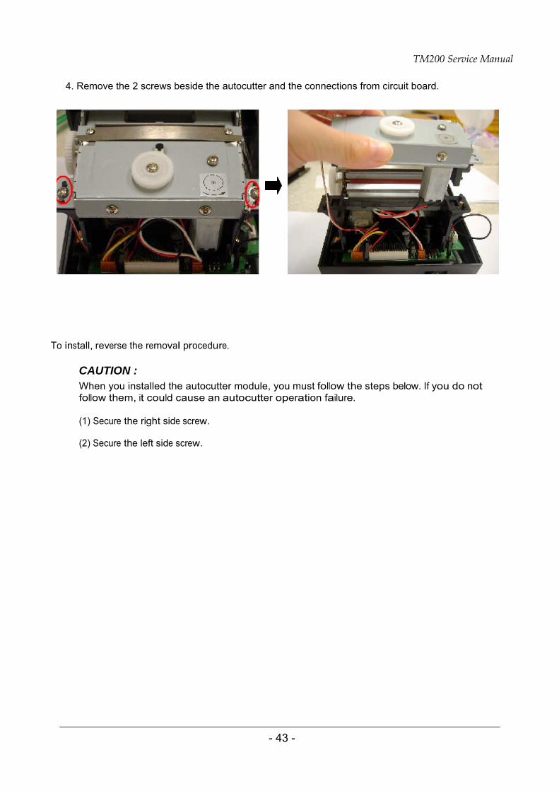
4. Remove the 2 screws beside the autocutter and the connections from circuit board.
To install, reverse the removal procedure.
CAUTION : When you installed the autocutter module, you must follow the steps below. If you do not follow them, it could cause an autocutter operation failure.
(1) Secure the right side screw.
(2) Secure the left side screw.
TM200 Service Manual
- 44 -
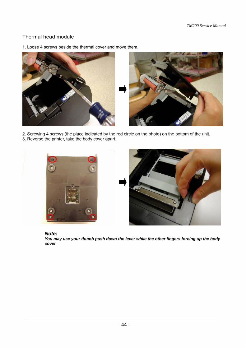
Thermal head module
1. Loose 4 screws beside the thermal cover and move them.
2. Screwing 4 screws (the place indicated by the red circle on the photo) on the bottom of the unit. 3. Reverse the printer, take the body cover apart.
Note: You may use your thumb push down the lever while the other fingers forcing up the body cover.
TM200 Service Manual
- 45 -
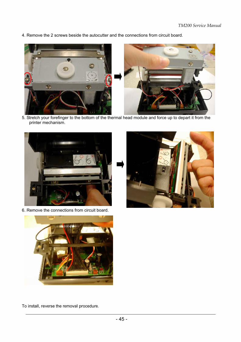
4. Remove the 2 screws beside the autocutter and the connections from circuit board.
5. Stretch your forefinger to the bottom of the thermal head module and force up to depart it from the printer mechanism.
6. Remove the connections from circuit board.
To install, reverse the removal procedure.
TM200 Service Manual
- 46 -
CAUTION: Note that the (thermal head) becomes very hot during normal operation, creating the danger of burn injury. Be sure to wait for about 10 minutes after turning printer power off before beginning the procedures.
When performing procedures, be sure to use a grounded wrist band or take other measures to protect against electrostatic charge. Failure to do so can result in damage to the (thermal head).
Never touch the thermal element (the area that looks like it is marked with a thin black line) of the (thermal head) with your hand. Doing so can damage the heating element.
Whenever there is dirt or any other foreign matter on the (thermal head), clean it off with a cotton swab moistened with alcohol.
When you installed the autocutter module, you must follow the steps below. If you do not follow them, it could cause an autocutter operation failure.
(1) Secure the right side screw. (2) Secure the left side screw.
TM200 Service Manual
- 47 -
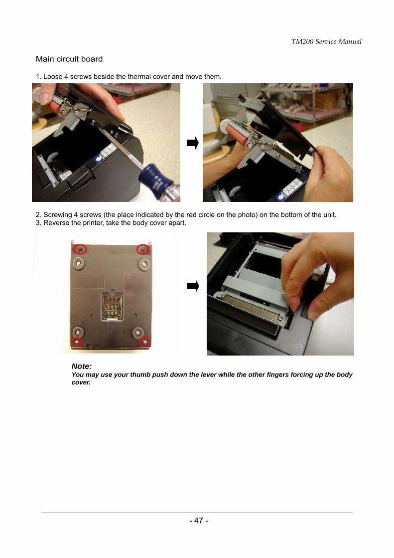
Main circuit board 1. Loose 4 screws beside the thermal cover and move them.
2. Screwing 4 screws (the place indicated by the red circle on the photo) on the bottom of the unit. 3. Reverse the printer, take the body cover apart.
Note: You may use your thumb push down the lever while the other fingers forcing up the body cover.
TM200 Service Manual
- 48 -
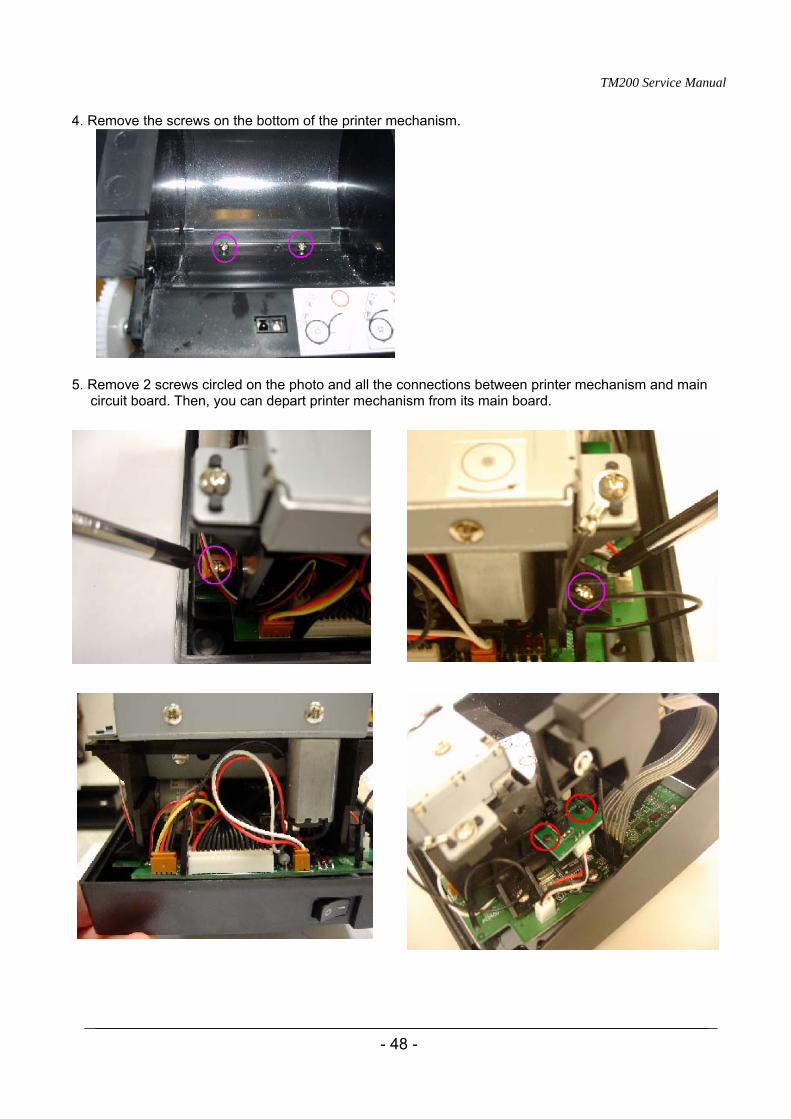
4. Remove the screws on the bottom of the printer mechanism.
5. Remove 2 screws circled on the photo and all the connections between printer mechanism and main circuit board. Then, you can depart printer mechanism from its main board.
TM200 Service Manual
- 49 -
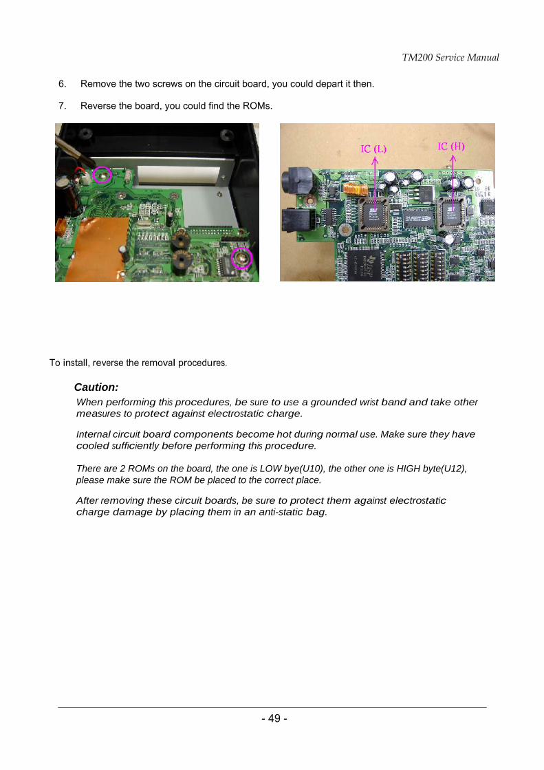
6. Remove the two screws on the circuit board, you could depart it then. 7. Reverse the board, you could find the ROMs.
To install, reverse the removal procedures.
Caution: When performing this procedures, be sure to use a grounded wrist band and take other measures to protect against electrostatic charge.
Internal circuit board components become hot during normal use. Make sure they have cooled sufficiently before performing this procedure. There are 2 ROMs on the board, the one is LOW bye(U10), the other one is HIGH byte(U12), please make sure the ROM be placed to the correct place.
After removing these circuit boards, be sure to protect them against electrostatic charge damage by placing them in an anti-static bag.
TM200 Service Manual
- 50 -
Appendix A Interface IEEE 1284 Bidirectional Parallel Interface
Specifications
Data transmission: 8-bit Parallel
Synchronization: Externally supplied P-/STROBE signals
Handshaking: P-/Ack and P-BUSY signals
Signal levels: TTL compatible
Reverse communication (Printer Host): Nibble or Byte Mode
Switching between online and offline
The printer is not equipped with any online/offline switch. The printer is placed into offline status in either of the followings:
1. When the power is turned on or until the printer becomes ready for data transmission after it is
initialized by the reset signal from the interface.
2. During the self-test.
3. When the cover is open.
4. During paper feeding using the paper feed button.
5. When the printer stops printing due to a paper-end (in cases when empty paper supply is detected by either the paper roll end detector or the paper roll near-end detector with a printing halt due to paper shortage enabled by ESC c 4).
6. During macro executing standby status.
7. When a temporary abnormality occurs in the power supply voltage.
8. When an error has occurred.
TM200 Service Manual
- 51 -
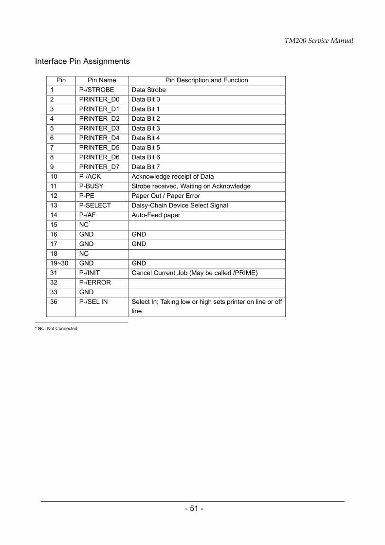
Interface Pin Assignments
Pin Pin Name Pin Description and Function 1 P-/STROBE Data Strobe 2 PRINTER_D0 Data Bit 0 3 PRINTER_D1 Data Bit 1 4 PRINTER_D2 Data Bit 2 5 PRINTER_D3 Data Bit 3 6 PRINTER_D4 Data Bit 4 7 PRINTER_D5 Data Bit 5 8 PRINTER_D6 Data Bit 6 9 PRINTER_D7 Data Bit 7 10 P-/ACK Acknowledge receipt of Data 11 P-BUSY Strobe received, Waiting on Acknowledge 12 P-PE Paper Out / Paper Error 13 P-SELECT Daisy-Chain Device Select Signal 14 P-/AF Auto-Feed paper 15 NC* 16 GND GND 17 GND GND 18 NC 19~30 GND GND 31 P-/INIT Cancel Current Job (May be called /PRIME) 32 P-/ERROR 33 GND 36 P-/SEL IN Select In; Taking low or high sets printer on line or off
line
* NC: Not Connected
TM200 Service Manual
52
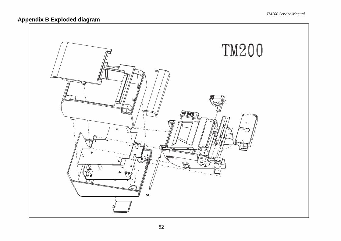
Appendix B Exploded diagram
TM200 Service Manual
- 53 -
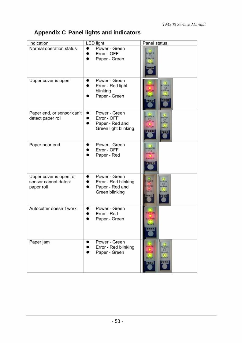
Appendix C Panel lights and indicators
Indication LED light Panel status Normal operation status Power - Green
Error - OFF Paper - Green
Upper cover is open Power - Green
Error - Red light blinking
Paper - Green
Paper end, or sensor can’t detect paper roll
Power - Green Error - OFF Paper - Red and
Green light blinking
Paper near end Power - Green
Error - OFF Paper - Red
Upper cover is open, or sensor cannot detect paper roll
Power - Green Error - Red blinking Paper - Red and
Green blinking
Autocutter doesn’t work Power - Green
Error - Red Paper - Green
Paper jam Power - Green
Error - Red blinking Paper - Green
TM200 Service Manual
- 54 -
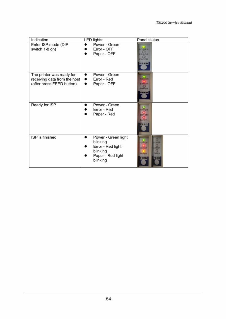
Indication LED lights Panel status Enter ISP mode (DIP switch 1-8 on)
Power - Green Error - OFF Paper - OFF
The printer was ready for receiving data from the host (after press FEED button)
Power - Green Error - Red Paper - OFF
Ready for ISP Power - Green
Error - Red Paper - Red
ISP is finished Power - Green light
blinking Error - Red light
blinking Paper - Red light
blinking
TM200 Service Manual
- 55 -
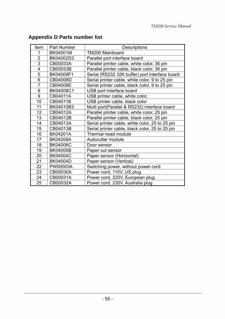
Appendix D Parts number list
Item Part Number Descriptions 1 BK04001M TM200 Mainboard 2 BK04002D3 Parallel port interface board 3 CB00033A Parallel printer cable, white color, 36 pin 4 CB00033B Parallel printer cable, black color, 36 pin 5 BK04009F1 Serial (RS232 32K buffer) port interface board 6 CB04008D Serial printer cable, white color, 9 to 25 pin 7 CB04008E Serial printer cable, black color, 9 to 25 pin 8 BK04008C1 USB port interface board 9 CB04011A USB printer cable, white color, 10 CB04011B USB printer cable, black color 11 BK04010B3 Multi port(Parallel & RS232) interface board 12 CB04012A Parallel printer cable, white color, 25 pin 13 CB04012B Parallel printer cable, black color, 25 pin 14 CB04013A Serial printer cable, white color, 25 to 25 pin 15 CB04013B Serial printer cable, black color, 25 to 25 pin 16 BK04201A Thermal head module 17 BK04208A Autocutter module 18 BK04006C Door sensor 19 BK04005B Paper out sensor 20 BK04004C Paper sensor (Horizontal) 21 BK04004D Paper sensor (Vertical) 22 PW00003A Switching power, without power cord 23 CB00030A Power cord, 110V, US plug 24 CB00031A Power cord, 220V, European plug 25 CB00032A Power cord, 230V, Australia plug