Embed Size (px)
Citation preview
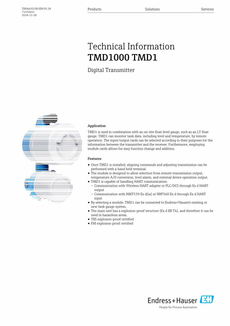
Application
TMD1 is used in combination with an on-site float level gauge, such as an LT floatgauge. TMD1 can monitor tank data, including level and temperature, by remoteoperation. The input/output cards can be selected according to their purposes for theinformation between the transmitter and the receiver. Furthermore, employingmodule cards allows for easy function change and addition.
Features
• Once TMD1 is installed, aligning commands and adjusting transmission can beperformed with a hand held terminal.
• The module is designed to allow selection from remote transmission output,temperature A/D conversion, level alarm, and external device operation output.
• TMD1 is capable of handling HART communication.– Communication with Wireless HART adapter or PLC/DCS through Ex d HART
output– Communication with NMT539 Ex d[ia] or NRF560 Ex d through Ex d HART
input• By selecting a module, TMD1 can be connected to Endress+Hauser's existing or
new tank gauge system.• The main unit has a explosion-proof structure (Ex d IIB T4), and therefore it can be
used in hazardous areas.• TIIS explosion-proof certified• FM explosion-proof certified
Products Solutions Services
Technical InformationTMD1000 TMD1Digital Transmitter
TI00463G/00/EN/03.18714346452018-12-28

TMD1000 TMD1
2 Endress+Hauser
Table of contents
About this document . . . . . . . . . . . . . . . . . . . . . . . . 3Symbol . . . . . . . . . . . . . . . . . . . . . . . . . . . . . . . . . . . . 3Registered trademarks . . . . . . . . . . . . . . . . . . . . . . . . . . 5
Functions and system configuration . . . . . . . . . . . . . 6NMT53x & NRF560 combination (HART communication) . . 6Combination with spot temperature device . . . . . . . . . . . . 6Combination with NMT539 Ex d[ia] (TIIS only) . . . . . . . . . 7Combination with RCV and DRM9700 (TIIS only) . . . . . . . . 8Operating Principle . . . . . . . . . . . . . . . . . . . . . . . . . . . . 9Configuration diagram . . . . . . . . . . . . . . . . . . . . . . . . . 11
Input/Output . . . . . . . . . . . . . . . . . . . . . . . . . . . . . 12Temperature input . . . . . . . . . . . . . . . . . . . . . . . . . . . . 124 to 20 mA input . . . . . . . . . . . . . . . . . . . . . . . . . . . . . 12Contact point input (status) . . . . . . . . . . . . . . . . . . . . . . 12HART output . . . . . . . . . . . . . . . . . . . . . . . . . . . . . . . 132-wire digital output . . . . . . . . . . . . . . . . . . . . . . . . . . 13BCD parallel output . . . . . . . . . . . . . . . . . . . . . . . . . . . 14SAKURA code parallel output . . . . . . . . . . . . . . . . . . . . 14Optical (FFi) communication . . . . . . . . . . . . . . . . . . . . . 144 to 20 mA output . . . . . . . . . . . . . . . . . . . . . . . . . . . . 14Contact output (Alarm) . . . . . . . . . . . . . . . . . . . . . . . . 15External device operation output . . . . . . . . . . . . . . . . . . 15Relay contact output (alarm) . . . . . . . . . . . . . . . . . . . . . 15Allowable load impedance . . . . . . . . . . . . . . . . . . . . . . 15Standard TMD1 terminal table . . . . . . . . . . . . . . . . . . . . 16A - 3 H terminal table . . . . . . . . . . . . . . . . . . . . . . . . . 16A - 2 H terminal table . . . . . . . . . . . . . . . . . . . . . . . . . 17B - 2 H terminal table . . . . . . . . . . . . . . . . . . . . . . . . . . 18B - 3 H terminal table . . . . . . . . . . . . . . . . . . . . . . . . . . 19C H terminal table . . . . . . . . . . . . . . . . . . . . . . . . . . . . 20E - 1 H terminal table . . . . . . . . . . . . . . . . . . . . . . . . . . 21550 H terminal table . . . . . . . . . . . . . . . . . . . . . . . . . . 22A - 2 H Optical FFi terminal table . . . . . . . . . . . . . . . . . . 23
Power supply . . . . . . . . . . . . . . . . . . . . . . . . . . . . . 25Power consumption . . . . . . . . . . . . . . . . . . . . . . . . . . . 25Cable entry . . . . . . . . . . . . . . . . . . . . . . . . . . . . . . . . . 25Level A/D conversion . . . . . . . . . . . . . . . . . . . . . . . . . . 25
Performance characteristics . . . . . . . . . . . . . . . . . . 26Performance characteristics of tank side monitor . . . . . . . 26
Installation . . . . . . . . . . . . . . . . . . . . . . . . . . . . . . . 27Installation location . . . . . . . . . . . . . . . . . . . . . . . . . . . 27Structure . . . . . . . . . . . . . . . . . . . . . . . . . . . . . . . . . . 28Installation onto a tank . . . . . . . . . . . . . . . . . . . . . . . . 31
Environment . . . . . . . . . . . . . . . . . . . . . . . . . . . . . . 33Ambient temperature range . . . . . . . . . . . . . . . . . . . . . 33Water-proof dust-proof structure . . . . . . . . . . . . . . . . . . 33Surge arrester . . . . . . . . . . . . . . . . . . . . . . . . . . . . . . . 33
Operability . . . . . . . . . . . . . . . . . . . . . . . . . . . . . . . 34HHT2 (Hand Held Terminal) . . . . . . . . . . . . . . . . . . . . . 34
Certificates and approvals . . . . . . . . . . . . . . . . . . . 35Ex Approval . . . . . . . . . . . . . . . . . . . . . . . . . . . . . . . . 35
Order information . . . . . . . . . . . . . . . . . . . . . . . . . 36
Accessories . . . . . . . . . . . . . . . . . . . . . . . . . . . . . . . 37Coupling . . . . . . . . . . . . . . . . . . . . . . . . . . . . . . . . . . 37
Documentation . . . . . . . . . . . . . . . . . . . . . . . . . . . . 38Operating Instructions (BA) . . . . . . . . . . . . . . . . . . . . . 38Safety Instructions (XA) . . . . . . . . . . . . . . . . . . . . . . . . 38

TMD1000 TMD1
Endress+Hauser 3
About this document
Symbol Safety symbols
Symbol Meaning
DANGER
DANGER!This symbol alerts you to a dangerous situation. Failure to avoid this situation willresult in serious or fatal injury, as well as a risk of fire or explosion.
WARNING
WARNING!This symbol alerts you to a dangerous situation. Failure to avoid this situation willresult in a risk of serious or fatal injury, fire or explosion.
CAUTION
NoteThis symbol alerts you to a dangerous situation. Failure to avoid this situation willresult in a risk of minor or moderate injury and damages to properties.
NOTICE
NOTE!This symbol contains information on procedures and other facts that do not result inpersonal injury.
Electrical symbols
Symbol Meaning
Direct current
Alternating current
Direct current and alternating current
Ground connectionA grounded terminal that, as far as the operator is concerned, is grounded via agrounding system.
Protective ground connectionA terminal that must be connected to the ground prior to establishing any otherconnections.
Equipotential connectionThis connects with the grounding system at the plant.It includes equipotential line andsingle point ground systems, depending on the norms of each country or company.
Tool symbols
Symbol Meaning
A0013442
Torx screwdriver
A0011220
Flat blade screwdriver
A0011219
Phillips screwdriver
A0011221
Allen key
A0011222
Open-ended wrench

TMD1000 TMD1
4 Endress+Hauser
Symbols for certain types of information
Symbol Meaning
PermittedProcedures, processes or actions that are permitted
PreferredProcedures, processes or actions that are preferred
ForbiddenProcedures, processes or actions that are forbidden
TipIndicates additional information
Reference to documentation
A Reference to page
Reference to graphic
Notice or individual step to be observed
1. , 2. , 3. … Series of steps
Result of an operation or commissioning
Help in the event of a problem
Visual inspection
Operation via the local display
Operation via operating tool
Write-protected parameter
Symbols in graphics
Symbol Meaning
1, 2, 3 ... Item numbers
1. , 2. , 3. … Series of steps
A, B, C, ... Graphics
A-A, B-B, C-C, ... Cross-sections
-Hazardous areaIndicates the hazardous area
.Safe area (non-hazardous area)Indicates the non-hazardous area
Device symbol
Symbol Meaning
Safety instructionsObserve the safety instructions contained in the associated Operating Instructions.
Temperature resistance of the connection cablesSpecifies the minimum value of the temperature resistance of the connection cables.

TMD1000 TMD1
Endress+Hauser 5
Registered trademarks HART®Registered trademark of the HART Communication Foundation, Austin, USA

TMD1000 TMD1
6 Endress+Hauser
Functions and system configuration
NMT53x & NRF560combination (HARTcommunication)
TMD1 can be connected to Promonitor NRF560 instead of DRM9700 and average temperaturedevice Prothermo NMT53x equipped with a HART communication function. For specifications ofHART devices, contact your Endress+Hauser Sales Center.
NMT53x has two types of HART communication. Since TMD1 is Ex d (XP) type, an additionalbarrier is required in order to connect with NMT53x's Ex i type.
• NMT53x Ex i output (ATEX, IECEx, FM, NEPSI)• NMT53x Ex d [ia] output (TIIS only)
Combination with spottemperature device
Using conventional communication, tank information can be selected from various input/outputcards depending on the needs, and the functions can be changed and added easily with modulecards.
C
D
A
B
3
4
561
98
7
2
A0038054
1 Combination with spot temperature device
A Host communication systemB Digital outputC Local HART (Ex d) communicationD Contact point input (status)1 Float2 Spot temperature device3 Browser4 Tankvision5 Digital Transmitter TMD1000 TMD16 Float Level Gauge LT57 Promonitor NRF5608 Converter NRR2619 Oil Leak Detector NAR300

TMD1000 TMD1
Endress+Hauser 7
Combination with NMT539Ex d[ia] (TIIS only)
1
23
4
67
8 910
5
A
A
C
E
B
D
A0038055
2 HART Ex d [ia] output system configuration
A Contact point input (status)B Local HART (Ex d) communicationC Host communication systemD Digital outputE Local HART (Ex d) communication1 Level switch MPC2 Average temperature device NMT5393 Browser4 Tankvision5 Digital Transmitter TMD1000 TMD16 Float Level Gauge LT57 Float8 Oil Leak Detector NAR3009 Converter NRR26110 Promonitor NRF560

TMD1000 TMD1
8 Endress+Hauser
Combination with RCV andDRM9700 (TIIS only)
Using conventional communication, tank information can be selected from various input/outputcards depending on the needs, and the functions can be changed and added easily with modulecards.
1
23
4
67
8 9 10
5
A
A
B
C
A0038056
3 System configuration of RCV and DRM9700 combination
A Contact point input (status)B Host communication systemC Digital outputD Digital output1 Level switch MPC2 Average temperature device RCV3 Browser4 Tankvision5 Digital Transmitter TMD1000 TMD16 Float Level Gauge LT57 Float8 Oil Leak Detector NAR3009 Converter NRR26110 Tank Gauge Monitor DRM9700

TMD1000 TMD1
Endress+Hauser 9
Operating Principle Detection configuration
The changing amounts of tape or wire which corresponds to the level detected by a float level gauge(LT5) is converted to rotational angle and then transmitted inside the transmitter by means ofcoupling of the float level gauge and transmitter. The level's rotational change is transmitted to thelevel encoder and is digitally converted via gear unit and timing belt. The converted level is calculatedand diagnosed by a microprocessor and the level, its alarm, and temperature element switching aredigitally controlled, and digitally or analog transmitted along with other information.
1
23 4
6
7
8 9 10
5
D
AB
C C E F
811
0 - 99999 mm
0 - 99999 mm
A0038057
4 Detection configuration
A Float Level Gauge LT5B Digital Transmitter TMD1000 TMD1C To external devicesD Status input / Alarm outputE 2-way communicationF HART device1 Coupling (connected to a level gauge)2 Gear unit3 Low-order digit encoder4 Level A/D I/F module5 Timing belt6 High-order digit encoder7 Bus line8 Various I/O modules9 Exp module10 CPU module11 HHT2 (Hand Held Terminal)

TMD1000 TMD1
10 Endress+Hauser
Gear unit
Change in the tape travel distance, which the float gauge corresponds to the detecting level, isconverted to rotational angle inside the float level gauge and then transmitted to inside transmitterby the coupling of level gauge and transmitter. The gear mechanism applies acceleration adjustmentto this signal and runs the level encoder.
Level encoder
The level encoder is comprised of both a low-order digit level encoder and a high-order digit levelencoder.
Low-order encoder
When the disc which contains patterns rotates, the light which has passed through the slit is eitherpassed through along the pattern or is blocked. The light that passed through the pattern isconverted to an electrical signal by the light-receiving element and then output to themicroprocessor.
High-order encoder
The high-order encoder is comprised of a counter and an optic reader, and it optically reads codesalong the circumference of the mechanical counter's drum. The level is converted to a gray code,which is a combination of ON and OFF signal, and then output to the microprocessor.
12
3
4
5
6
A0038058
5 Level encoder
1 Optical transistor2 LED3 Slit4 Disk5 Counter6 Optical sensor
TMD1000 TMD1
Endress+Hauser 11
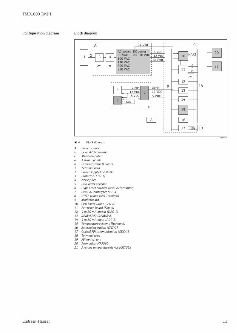
Configuration diagram Block diagram
HART
AC power60 VAC100 VAC110 VAC200 VAC220 VAC
DC power20 - 30 VDC
1 2 3 4
24 VDC
5
6
7
A
B
C
912 bits
12 VDC
5 VDC
10 bits
5 VDC
5 VDC
12 VDC
12 Vin
Serial
12 Vout
8
10
11
12
13
14
15
16
17
18
19
20
21
V1
FFi
ab
A0038059
6 Block diagram
A Power sourceB Level A/D converterC Microcomputera Alarm 8 pointsb External status 8 points1 Terminal area2 Power supply line shield3 Protector (ARS-1)4 Noise filter5 Low-order encoder6 High-order encoder (level A/D counter)7 Level A/D interface MIF-48 HHT2 (Hand Held Terminal)9 Motherboard10 CPU board (Main-CPU-B)11 Extension board (Exp-A)12 4 to 20 mA output (DAC-1)13 DRM-9700 (DRMM-A)14 4 to 20 mA input (ADC-2)15 Temperature system (Thermo-A)16 External operation (CNT-2)17 Optical FFi communication (ODC-1)18 Terminal area19 FFi optical unit20 Promonitor NRF56021 Average temperature device NMT53x

TMD1000 TMD1
12 Endress+Hauser
Input/Output
Temperature input TMD1 can connect to a temperature measuring device and collect temperature data inside the tank.
Average temperature device Prothermo NMT53x
NMT53x is an intelligent-type average temperature device in which an electrical compartment isinstalled on top of a flexible tube with a built-in temperature element, and a HART communicationmodule for A/D conversion installed on the temperature device side.
TMD1's HART output function cannot be used if TMD1 is used in HART input mode in order toconnect to NMT53x or NRF560. Conversely, HART input function cannot be used if TMD1 isbeing used in HART output mode.
TMD1 internal module None (the following shows Prothermo NMT539 series main unit's data)
Communication method HART (local HART protocol) 2-wire transmission
Corresponding temperature element Pt100 measuring temperature resistor
A/D conversion range –200 to 235 °C (–328 to 455 °F)
Conversion accuracy ±0.1 °C (32.2 °F)
Resolution 0.01 °C (32.01 °F)
Temperature element points Maximum 16 points
RCV series average temperature device
TMD1 internal module Thermo-A
Corresponding temperature element Pt100 measuring temperature resistor
A/D conversion range –200.9 to 240 °C (–329.6 to 464 °F)
Conversion accuracy ±0.15 °C (32.27 °F)
Resolution 0.1 °C (32.2 °F)
Temperature element points Maximum 12 points
4 to 20 mA input TMD1 imports the external 4 to 20 mA current output device's data, and it is able to add said data toa 2-wire transmission (V1) signal and output it.
Module ADC-2
Input points 1 data
Data conversion accuracy ±0.3 °C (32.54 °F)
Input signal 4 to 20 mA
Input resistance 250 Ω
Supply voltage 24 V DC
Current capacity 60 mA
Contact point input (status) It imports data from external device with contact point output, such as oil leak detector or PC Series'level switch, and it can output the contact point output as a status signal to a high-order receiver.
Module Exp-A
Input points Standard 4 points (max. 8 points)
Input rating DC 30 V, DC 30 mA
Circuit power DC 12 V, DC 4 mA/per circuit
Circuit resistance Maximum 100 Ω/ 1 line (including contact point resistance)

TMD1000 TMD1
Endress+Hauser 13
HART output Ex d HART output allows for communication with Wireless HART adapter or with PLC/DCS.
Output function Local HART
It can be used as a generic HART device, but does not have a DD (FDT/DTM) that is registered with the HART Federation.
Output format Can be selected from HART active or passive
Types of HART value output • PV: Level• SV: Temperature• TV: Status of status input 1• QV: Status of status input 2
4x relay control can be applied when SWA70 and SWG70 are usedtogether. For details, contact your Endress+Hauser Sales Center.
Level unit • mm• ft• in
HHT2 displays level only in ISO unit (mm: millimeter).When setting upinch (in) or feet (ft) tank, manually convert the values to millimeter.
Temperature unit • Celsius degree (mm)• Fahrenheit (ft or in)
Output current 4 mA
It is fixed to 4 mA so that it is compatible with Multidrop. Point-to-Point 4 to 20 mA cannot be used.
• For analog 4 to 20 mA output in which HART is not superimposed, it can be used fromanother port (terminal) by selecting an output option of 010 or 040 specifications.
• Since TMD1 is explosion proof, note that it cannot be connected directly in an explosion-proof area when an intrinsic safety Wireless HART adapter is being used.
• Note that HART input for connecting to NMT539 or NRF560 cannot be used functionallywhen the HART port is used for HART output.
2-wire digital output Digital 2-wire transmission communication, which can efficiently control measuring data for severalexisting tanks, is an important function in modern tank gauges. TMD1 uses V1 communicationwhich is a tank gauge standard protocol of Endress+Hauser, and it can handle a communicationdistance of up to 6 km (total loop length).
Module Exp-A
Communication method 2-way, 2-wire serial digital pulse transmission
Level output 0 to 89.999 mm
Temperature output –49.9 to 199.9 °C (–57.82 to 391.82 °F)
Contact point output (alarm) (see Hint) Standard 4 points (max. 8 points)
Contact point input (status) (see Hint) Standard 4 points (max. 8 points)
Communication address 0 to 225
Level transmission error ±0 mm
Temperature transmission error ±0.0 °C
Response speed Within 180 ms/unit
Transmission range 6 km (3.73 mi) (when using CPEVφ1.2)
Line resistor Maximum 120 Ω/line
Line capacitance 0.3 µF/loop
Select contact output (alarm) and contact input (status) as an output 2 and input function.
TMD1000 TMD1
14 Endress+Hauser
BCD parallel output TMD1 is capable of handling BCD parallel output. In BCD output, either collector common or emittercommon can be selected.
Module • OUT-3 (collector common)• OUT-4 (emitter common)
Communication method Digital parallel transmission
Level output • Standard: 0 to 19.999 mm• Special: 0 to 7.9999 mm
Temperature output –49.9 to 199.9 °C (–57.82 to 391.82 °F)
Number of wires Standard: 17 bit + 1 common (total 18 wires)
Transmission output error ± 0 (level and temperature)
SAKURA code parallel output TMD1 is capable of handling SAKURA code parallel output. In SAKURA code parallel output, eithercollector common or emitter common can be selected.
Module • OUT-3 (collector common)• OUT-4 (emitter common)
Communication method Digital parallel transmission
Level output • Standard: 0 to 19.999 mm• Special: 0 to 39.999 mm
Temperature output None
Number of wires Standard: 17 bit + 1 common (total 18 wires)
Transmission output error ± 0 (level)
Optical (FFi) communication Optical communication specification can be selected when using in lightning prone areas. Becausethe optical communication's characteristics, it can minimize the external stress such as electricalnoise, and it can send and receive stable data.
Module ODC-1
Communication method 2-way and half double optical digital pulse communication (FFiprotocol)
Level output 0 to 65.535 mmor±32 767 mm (can be set with HHT2)
Temperature output –49.9 to 199.9 °C (–57.82 to 391.82 °F)
Main status output Over and under tension, level A/D conversion error, level flow error
Level alarm output H (upper limit) and L (lower limit) alarm, each 1 point
Displacer balance output Balance or unbalance
External status output 4 points
TGM5 control and operationinformation
Hoisting, measurement, stop
Optic fiber for communication Step index 100/140 µm (110/150 µm is also available)
4 to 20 mA output 4 to 20 mA current output is a method for transmitting measurement data to a high-order receiverin a simple and secure way despite being a high-order system. The system can be configuredindependently from the loop control data transmission and receipt with digital signal, and it can beconnected to an analog bar graph of a receiver, etc.
Module DAC-1(2 modules can be installed)
Communication method 4 to 20 mA Current outputs
Input points 1 data (2 data when using 2 modules)
Data conversion accuracy ±0.3 %

TMD1000 TMD1
Endress+Hauser 15
Rating 4 to 20 mA
Input allowable impedance 600 Ω
Contact output (Alarm) TMD1 is used not only as a transmitter but also as a level alarm sensor of inventory control tooperate tank yard safely. By setting conditions for measurement data such as level and temperature,the alarm can output warning with relay contact with conditions that would exceed (or not reach)the range.
Module Exp-A
Output method Transistor (photo coupler) contact point
Output setting Level and temperature
Output points Standard 4 points (max. 8 points)
Output rating Open collector output by photo coupler
Collector current 30 mA
Voltage between collector and emitter Max. 250 V
External device operationoutput
External devices, such as valves, are controlled by operating relays via operation commands from adedicated receiver. Because the relay uses a latching type, the contact status of relays is maintainedeven during power outages.
Module CNT-2
Output method Relay contact point
Output setting External device control
Output points Standard 6 or 8 points depending on use (max. 8 points)
Number of wires 16C (8 points)
Contact capacity DC220 V/AC250 V, 3 A, 60 W/ 125 VA
Relay contact output (alarm) Module Exp-A + CD688
Output method Relay contact point output (contact point A)
Output setting Level and temperature
Output points Standard 4 points, independent common
Accuracy ±0 with respect to level or temperature data
Output rating AC100 V 0.5 A, DC30 V 0.5 A
Allowable load impedance E and R are determined so that the following equation is satisfied.
Is (A) ≤ ≤ 0.03 (A)! ! ! ! ! ! !R ( ) + 2r ( )Ω Ω
E (V) - 1.2 (V)
A0038061

TMD1000 TMD1
16 Endress+Hauser
ab
c
r (Ω)
r (Ω)
VOE1.2V
A0038060
7 Allowable load impedance of TMD1 and contact output circuit
a Max. 30 mAb Load R(Ω) / Operating current Is
Example: Transmission distance calculation on wiring
• The purpose of this calculation is to calculate the limitation between resistance and capacitancebetween the following lines.– Unidirectional resistance: Max. 120 Ω– Max. capacitance between lines: Max. 0.3 µF
• Maximum capacitance between lines and cable resistance (see table below)
Cable name Conductorresistance(Ω/km)
Capacitance(μF/km)
Max. transmissiondistance(km)
Note
CPEV, CPEE Ø0.9 Max. 30 Max. 0.05 4 Calculated based on30 Ω
KMPEV. KPEV-SKMPEE0.9 mm2
Max. 21.5 0.05 5.58 Calculated based on21.5 Ω
CPEV Ø1.2 16.5 0.05 6 Calculated based on0.05 µF
CPEV (T) Ø0.9 Max. 30 0.06 4 Calculated based on30 Ω
CVV2 mm2 (CEE) 9.5 0.09(0.06)
3.3 (5) Calculated based on 0.09(0.06) µF
Standard TMD1 terminaltable
Terminal assignment and internal wiring of TMD1 vary depending on the selected specifications.Specific cable patterns are determined according to their functions and combination of input andoutput. The following cable patterns are only a partial excerpt and the patterns vary depending ontheir specifications.
A - 3 H terminal table 4~20 mA analog current output, DRM9700 output, contact point alarm output, spottemperature device (1 point)
TerminalNo.
Signal name Polarity ConnectorNo.
Connectionboard
Remarks
1 Supply power AC /DC + AC has no polarity
2 -
3
4
5
6
7 DC 4 to 20 mA output + 4 DAC-1
8 -
9 DC 4 to 20 mA output + 8 DAC-1
10 -
11 DRM9700 output + 5 DRMM-A

TMD1000 TMD1
Endress+Hauser 17
TerminalNo.
Signal name Polarity ConnectorNo.
Connectionboard
Remarks
12 -
13
14
15 HART communication + Main-CPU-B Connection for HARTinput (NRF and NMT)or HART output16 -
17 Alarm output 1 + J-3 Exp-A
18 -
19 Alarm output 2 +
20 -
21 Alarm output 3 +
22 -
23 Alarm output 4 +
24 -
25 Spot temperature input (A) 2 Thermo-A Simultaneousoperation with NMT-type averagetemperature device isprohibited.
26 Spot temperature input (B)
27 Spot temperature input (b)
28
29
30
31
32
33
34
35
36
A - 2 H terminal table 2-way, 2-wire transmission, 4 to 20 mA analog current output, DRM9700 output, contact pointalarm output, status input spot temperature device (1 point), level gauge operation output
TerminalNo.
Signal name Polarity ConnectorNo.
Connectionboard
Remarks
1 Supply power AC/DC + AC has no polarity
2 -
3 Level gauge operationoutput: hoisting common
6 CNT-2
4 Level gauge operationoutput: hoisting
5 Level gauge operationoutput: stop common
6 Level gauge operationoutput: stop
7 2-way, 2-wire transmission 1 Exp-A
8
9 DC 4 to 20 mA output + 4 DAC-1

TMD1000 TMD1
18 Endress+Hauser
TerminalNo.
Signal name Polarity ConnectorNo.
Connectionboard
Remarks
10 -
11 DRM9700 output + 5 DRMM-A
12 -
13 DC4 to 20 mA input + 7 ADC-2
14 -
15 HART communication + Main-CPU-B Connection for HARTinput (NRF and NMT)or HART output16 -
17 Alarm output 1 + J-3 Exp-A
18 -
19 Alarm output 2 +
20 -
21 Alarm output 3 +
22 -
23 Alarm output 4 +
24 -
25 Spot temperature input (A) 2 Thermo-A Simultaneousoperation with NMT-type averagetemperature device isprohibited.
26 Spot temperature input (B)
27 Spot temperature input (b)
28
29 Status input 1 + J-4 Exp-A
30 -
31 Status input 2 +
32 -
33 Status input 3 +
34 -
35 Status input 4 +
36 -
B - 2 H terminal table 2-way, 2-wire transmission, 4 to 20 mA analog current output, DRM9700 output, contact pointalarm output, average temperature/spot temperature devices (3 points), level gauge operationoutput
TerminalNo.
Signal name Polarity ConnectorNo.
Connectionboard
Remarks
1 Supply power AC/DC + AC has no polarity
2 -
3 Level gauge operationoutput: hoisting common
6 CNT-2
4 Level gauge operationoutput: hoisting
5 Level gauge operationoutput: stop common
6 Level gauge operationoutput: stop
7 2-way, 2-wire transmission + 1 Exp-A

TMD1000 TMD1
Endress+Hauser 19
TerminalNo.
Signal name Polarity ConnectorNo.
Connectionboard
Remarks
8 -
9 DC 4 to 20 mA output + 4 DAC-1
10 -
11 DRM9700 output + 5 DRMM-A
12 -
13 DC4 to 20 mA input + 7 ADC-2
14 -
15 HART communication + Main-CPU-B Connection for HARTinput (NRF and NMT)or HART output16 -
17 Alarm output 1 + J-3 Exp-A
18 -
19 Alarm output 2 +
20 -
21 Alarm output 3 +
22 -
23 Alarm output 4 +
24 -
25 Average temperature input (B) 2 Thermo-A Simultaneousoperation with NMT-type averagetemperature device isprohibited.
26 Average temperature input (b)
27 Average temperature input (A1)/Spot 1 (A)
28 Average temperature input (A2)/Spot 1 (B)
29 Average temperature input (A3)/Spot 1 (b)
30 Average temperature input (A4)/Spot 2 (A)
31 Average temperature input (A5)/Spot 2 (B)
32 Average temperature input (A6)/Spot 2 (b)
33 Average temperature input (A7)/Spot 3 (A)
34 Average temperature input (A8)/Spot 3 (B)
35 Average temperature input (A9)/Spot 3 (b)
36 Average temperature input (A10)
B - 3 H terminal table 2-way, 2-wire transmission, 4 to 20 mA analog current output, DRM9700, output, contact pointalarm output, average temperature/spot temperature devices (3 points), level gauge operationoutput
TerminalNo.
Signal name Polarity ConnectorNo.
Connectionboard
Remarks
1 Supply power AC/DC + AC has no polarity
2 -
3 Level gauge operationoutput: hoisting common
6 CNT-2
4 Level gauge operationoutput: hoisting
5 Level gauge operationoutput: stop common

TMD1000 TMD1
20 Endress+Hauser
TerminalNo.
Signal name Polarity ConnectorNo.
Connectionboard
Remarks
6 Level gauge operationoutput: stop
7 2-way, 2-wire transmission + 1 Exp-A
8 -
9 DC 4 to 20 mA output + 4 DAC-1
10 -
11 DRM9700 output + 5 DRMM-A
12 -
13 DC 4 to 20 mA input + 7 ADC-2
14 -
15 HART communication + Main-CPU-B Connection for HARTinput (NRF and NMT)or HART output16 -
17 Alarm output 1 + J-4 Exp-A
18 -
19 Alarm output 2 +
20 -
21 Alarm output 3 +
22 -
23 Alarm output 4 +
24 -
25 Average temperature input (B) 2 Thermo-A Simultaneousoperation with NMT-type averagetemperature device isprohibited.
26 Average temperature input (b)
27 Average temperature input (A1)/Spot 1 (A)
28 Average temperature input (A2)/Spot 1 (B)
29 Average temperature input (A3)/Spot 1 (b)
30 Average temperature input (A4)/Spot 2 (A)
31 Average temperature input (A5)/Spot 2 (B)
32 Average temperature input (A6)/Spot 2 (b)
33 Average temperature input (A7)/Spot 3 (A)
34 Average temperature input (A8)/Spot 3 (B)
35 Average temperature input (A9)/Spot 3 (b)
36 Average temperature input (A10)
C H terminal table 2-way, 2-wire transmission, contact point alarm output, status input, average temperature/spot temperature devices (3 points)
TerminalNo.
Signal name Polarity ConnectorNo.
Connectionboard
Remarks
1 Supply power AC/DC +
2 -
3 HART communication + Main-CPU-B Connection for HARTinput (NRF and NMT)or HART output4 -
5

TMD1000 TMD1
Endress+Hauser 21
TerminalNo.
Signal name Polarity ConnectorNo.
Connectionboard
Remarks
6
7 2-way, 2-wire transmission + 1 Exp-A
8 -
9 Alarm output 1 + J-3 Exp-A
10 -
11 Alarm output 2 +
12 -
13 Alarm output 3 +
14 -
15 Alarm output 4 +
16 -
17 Status input 1 + J-4 Exp-A
18 -
19 Status input 2 +
20 -
21 Status input 3 +
22 -
23 Status input 4 +
24 -
25 Average temperature input (B) 2 Thermo-A Simultaneousoperation with NMT-type averagetemperature device isprohibited.
26 Average temperature input (b)
27 Average temperature input (A1)/Spot 1 (A)
28 Average temperature input (A2)/Spot 1 (B)
29 Average temperature input (A3)/Spot 1 (b)
30 Average temperature input (A4)/Spot 2 (A)
31 Average temperature input (A5)/Spot 2 (B)
32 Average temperature input (A6)/Spot 2 (b)
33 Average temperature input (A7)/Spot 3 (A)
34 Average temperature input (A8)/Spot 3 (B)
35 Average temperature input (A9)/Spot 3 (b)
36 Average temperature input (A10)
E - 1 H terminal table 4 to 20 mA Analog current output, contact point alarm output, status input, level/averagetemperature or spot temperature device (3 points)
TerminalNo.
Signal name Polarity ConnectorNo.
Connectionboard
Remarks
1 Supply power AC /DC + AC has no polarity
2 -
3 HART communication + Main-CPU-B Connection for HARTinput (NRF and NMT)or HART output4 -
5
6

TMD1000 TMD1
22 Endress+Hauser
TerminalNo.
Signal name Polarity ConnectorNo.
Connectionboard
Remarks
7 Common 1 OUT-3 orOUT-4
Use OUT-3 forcollector commonUse OUT-4 for emittercommonEither level ortemperature outputmust be selectedaccording tospecifications.
8 Level 100 -20/Temperature 10-1 -20
9 Level 100 -21/Temperature 10-1 -21
10 Level 100 -22/Temperature 10-1 -22
11 Level 100 -23/Temperature 10-1 -23
12 Level 101 -20/Temperature 10-1 -20
13 Level 101 -21/Temperature 10-0 -21
14 Level 101 -22/Temperature 10-0 -22
15 Level 100 -20/Temperature 10-1 -20
16 Level 102 -20/Temperature 10-1 -20
17 Level 102 -21/Temperature 10-1 -21
18 Level 102 -22/Temperature 10-1 -22
19 Level 102 -23/Temperature 10-1 -23
20 Level 103 -20/Temperature 10-2 -20
21 Level 103 -21/Temperature 10-2 -21
22 Level 103 -22/Temperature 10-2 -22
23 Level 103 -23/Temperature 10-2 -23
24 Level 104 -20/Temperature 10 +, -
25 DRM-9700 output + 5 DRMM-A
26 -
27 DC 4 to 20 mA output + 4 DAC-1
28 -
29 Alarm output 1 + J-3 Exp-A
30 -
31 Alarm output 2 +
32 -
33 Alarm output 3 +
34 -
35 Alarm output 4 +
36 -
550 H terminal table 2-way, 2-wire transmission, 4 to 20 mA analog current output, DRM9700 output, alarm output(relay), status input, spot temperature device (1 point), level gauge operation output
TerminalNo.
Signal name Polarity ConnectorNo.
Connectionboard
Remarks
1 Supply power AC /DC + AC has no polarity
2 -
3 Level gauge operationoutput: hoisting common
6 CNT-2
4 Level gauge operationoutput: hoisting
5 Level gauge operationoutput: stop common
TMD1000 TMD1
Endress+Hauser 23
TerminalNo.
Signal name Polarity ConnectorNo.
Connectionboard
Remarks
6 Level gauge operationoutput: stop
7 2-way, 2-wire transmission + 1 DAC-1
8 -
9 DC 4 to 20 mA output + 4 DAC-1
10 -
11 DRM9700 output + 5 DRMM-A
12 -
13 DC4 to 20 mA input + 7 ADC-2
14 -
15 HART communication + Main-CPU-B Connection for HARTinput (NRF and NMT)or HART outputHART input or output(depending on thespecifications)
16 -
17 Alarm output (relay) 1 J-3 Exp-A andCD-688
Because of mechanicalrelay for alarm output,CD-688 module issupplied.
18
19 Alarm output (relay) 2
20
21 Alarm output (relay) 3
22
23 Alarm output (relay) 4
24
25 Average temperature input(A)
A 2 Thermo-A Simultaneousoperation with NMT-type averagetemperature device isprohibited.
26 Average temperature input(B)
B
27 Average temperature input(b)
b
28
29 Status input 1 + J-4 Exp-A
30 -
31 Status input 2 +
32 -
33 Status input 3 +
34 -
35 Status input 4 +
36 -
A - 2 H Optical FFi terminaltable
4 to 20 mA analog current output, DRM9700 output, contact point alarm output, spottemperature device (1 point)
TerminalNo.
Signal name Polarity ConnectorNo.
Connectionboard
Remarks
1 Supply power AC
2

TMD1000 TMD1
24 Endress+Hauser
TerminalNo.
Signal name Polarity ConnectorNo.
Connectionboard
Remarks
3
4
5
6
7
8
9 DC 4 to 20 mA output + 4 DAC-1
10 -
11 DRM9700 output + 5 DRMM-A DRMM-A board isoptional.
12 -
13 DC4 to 20 mA input + 7 ADC-2
14 -
15 HART communication + Main-CPU-B Connection for HARTinput (NRF and NMT)or HART outputHART input or output(depending on thespecifications)
16 -
17 Alarm output 1 + J-3 Exp-A
18 -
19 Alarm output 2 +
20 -
21 Alarm output 3 +
22 -
23 Alarm output 4 +
24 -
25 Average temperature input(A)
2 Thermo-A Simultaneousoperation with NMT-type averagetemperature device isprohibited.
26 Average temperature input(B)
27 Average temperature input(b)
28
29 Status input 1 + J-4 Exp-A
30 -
31 Status input 2 +
32 -
33 Status input 3 +
34 -
35 Status input 4 +
36 -

TMD1000 TMD1
Endress+Hauser 25
Power supply• 60 VAC, 100 VAC, 110 VAC, 200 VAC, 220 VAC ±10 % 50/60 Hz• 20 to 32 VDC
DC power source cannot be used with FFi specification. For special power supply, contact yourEndress+Hauser Sales Center.
Power consumption AC Max. 14 W
DC Max. 10 W
Cable entry Code Spec.
0 A: PF(G)1-1/2, B: PF(G)3/4, C: PF(G)1, D: PF(G)1 (Thread positions are fixed. See externaldimensional drawing.)
H 2 x thread G1/EXPC-28B, 2x blind plug (The position of the thread hole can be specified by A, B, C, orD.)
J 3 x thread G1/EXPC-28B, 1x blind plug (The position of the thread hole can be specified by A, B, C, orD.)
K 4 x thread G1 EXPC-28B (The position of the thread hole can be specified by A, B, C, or D.)
L 2 x thread G3/4 /EXPC-22B, 2x blind plug (The position of the thread hole can be specified by A, B, C,or D.)
M 3 x thread G3/4 /EXPC-22B, 1x blind plug (The position of the thread hole can be specified by A, B, C,or D.)
N 4 x thread G3/4 EXPC-22B (The position of the thread hole can be specified by A, B, C, or D.)
P 4 x thread NPT 1
Q 4 x thread NPT 3/4
Level A/D conversion Method Optical non-contact absolute encoder
Capacity 0 to 99 999 mm
Accuracy ±1 mm (0.04 in)

TMD1000 TMD1
26 Endress+Hauser
Performance characteristics
Performance characteristicsof tank side monitor
Tank Gauge Monitor DRM9700
TMD1 incorporates DRMM-A module as output 2 and can output level and temperature data to tankgauge monitor DRM9700.
TMD1 module name DRMM-A
Communication method Single-way (unidirectional) serial digital pulse 2-wire transmission
Level display 0 to 99 999 mm (0 to 3 536 in)
Temperature display –999.9 to 999.9 °C (–1 767.8 to 1 831.8 °F)
Other display Gauge status
Line resistor Max. 6.0 Ω (Disconnection)
Line capacitance Max. 0.4 µF(CPEV cable φ1.2 = max. 4 km, φ0.9 = max. 2 lm
Promonitor NRF560
Promonitor NRF560 is characterized by its ability to send and receive data via HART communication;it does not have a unidirectional on-site monitor function.
Type Promonitor NRF560
Communication method HART (local HART protocol) 2-wire transmission
Level display 0 to 99 999.9 mm (0 to 3 536 in)
Temperature display –999.9 to 999.9 °C (–1 767.8 to 1 831.8 °F)
Other display Gauge status (measuring status), error status
• Because a standard TMD1 has a local HART communication board built into the Main CPU-B,it can connect directly to on-site monitor Promonitor NRF560 and average temperaturedevice Prothermo NMT53x without the need to add a circuit board.
• TMD1's HART output function cannot be used if TMD1 is used in HART input mode in orderto connect to NMT53x or NRF560.Conversely, HART input function cannot be used if TMD1is being used in HART output mode.

TMD1000 TMD1
Endress+Hauser 27
Installation
Installation location Digital Transmitter TMD1 is designed to be installed on the rear of a level gauge and placed outsidethe tank as shown below. This equipment (level gauge and transmitter) is primarily employed inmeasuring level, particularly for crude or other oil in refineries and storage tanks. Other applicationsmay include acid, alkaline fluid and fat products in chemical industry storage tanks.
1
2
A0038037
8 TMD Installation
1 Digital Transmitter TMD12 Float level gauge LT5

TMD1000 TMD1
28 Endress+Hauser
Structure Standard size
Ordering information 080 A cable gland is included with cable entry options H/J/K/L/M. In this case,the cable gland attached to the device must always be used. Options P/Q do not come with a cablegland.
14
0 (
5.5
1)
!1
80
(7.0
9)
11
8 (4
.65
)1
91
(7.5
2)
!1
36
(5.3
5)
28
0 (
11
.02
)
a
AB
C D
1
23
6
4
5
5
7
A0038038
9 TMD1 size (Standard) Unit: mm (in)
A Cable entry position AB Cable entry position BC Cable entry position CD Cable entry position Da 325 mm (12.79 in)(Non-FM specifications) / 335 mm (13.19 in)(FM specifications)1 Coupling (Material: ADC6/Quantity: 1)2 Electrical housing (Material: AC4C-T6/Quantity: 1)3 Cover of electrical housing (Material: AC4C-T6/Quantity: 1)4 Terminal box (Material: ADC12/Quantity: 1)5 Locking (Material: ADC6/Quantity: 2)6 Hand-held terminal connection port (Quantity: 1)7 Terminal box cover (AC4C-T6/Quantity: 1)
TMD1000 TMD1
Endress+Hauser 29
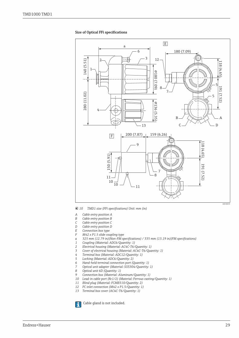
Size of Optical FFi specifications
11
8 (4
.65
)1
91
(7.5
2)
11
8 (4
.65
)1
91
(7.5
2)
AB
C D
14
0 (
5.5
1)
!1
80
(7.0
9)
!1
36
(5.3
5)
28
0 (
11
.02
)
a
1
23 12
6
4
5
5
78
8
180 (7.09)
200 (7.87) 159 (6.26)
15
0 (
5.9
1)
1010
11
11
9
7
13
E
F
A0038039
10 TMD1 size (FFi specifications) Unit: mm (in)
A Cable entry position AB Cable entry position BC Cable entry position CD Cable entry position DE Connection box typeF M42 x P1.5 slide coupling typea 325 mm (12.79 in)(Non-FM specifications) / 335 mm (13.19 in)(FM specifications)1 Coupling (Material: ADC6/Quantity: 1)2 Electrical housing (Material: AC4C-T6/Quantity: 1)3 Cover of electrical housing (Material: AC4C-T6/Quantity: 1)4 Terminal box (Material: ADC12/Quantity: 1)5 Locking (Material: ADC6/Quantity: 2)6 Hand-held terminal connection port (Quantity: 1)7 Optical unit adapter (Material: SUS304/Quantity: 1)8 Optical unit 6D (Quantity: 1)9 Connection box (Material: Aluminum/Quantity: 1)10 Lead-in cable port (Rc1/2) (Material: Ferrous casting/Quantity: 1)11 Blind plug (Material: FCMB310/Quantity: 2)12 FC inlet connection (M42 x P1.5/Quantity: 1)13 Terminal box cover (AC4C-T6/Quantity: 1)
Cable gland is not included.

TMD1000 TMD1
30 Endress+Hauser
Weight
10 kg (22 lb)
Material
• Electrical housing: AC4C-T6• Electrical housing cover: AC4C-T6• Terminal box: ADC12• Terminal box cover: AC4C-T6
Color
Blue and white

TMD1000 TMD1
Endress+Hauser 31
Installation onto a tank
1
2
3
4
5
5
6
7
8
4
6
7
8
1
23
1
A
B
A0038042
11 Installation (Standard)
A Standard installationB Special installation (See notes)1 Float level gauge2 TMD1 electric lid3 TMD1 terminal box4 Flexible fitting5 Cable gland or cable conduit6 Tumbler switch7 Flexible fitting8 Thick steel conduit tube
B in the drawing shows an installation that requires wire routing. This is not recommended as itis prone to letting in rain water through the cable entry.

TMD1000 TMD1
32 Endress+Hauser
1
2
3
4
56
7
8
9
10
1
2
5
67
8
9
10
4
3
A
B
A0038043
12 Installation (FFi Specification)
A Standard installationB Special installation (See notes)1 Float level gauge2 TMD1 electric lid3 TMD1 terminal box4 Connection box5 Flexible fitting for optical fiber6 Flexible fitting7 Cable gland or cable conduit8 Tumbler switch9 Flexible fitting10 Thick steel conduit tube
B in the drawing shows an installation that requires wire routing. This is not recommended as itis prone to letting in rain water through the cable entry.

TMD1000 TMD1
Endress+Hauser 33
Environment
Ambient temperature range Non-explosion proof/Explosion proof
–20 to 60 °C (–4 to 140 °F)
FFi Specifications –10 to 40 °C (14 to 104 °F)
Water-proof dust-proofstructure
IP65 / NEMA Type 4X
Surge arrester Supplied as standard

TMD1000 TMD1
34 Endress+Hauser
Operability
HHT2 (Hand Held Terminal) HHT2 is TIIS explosion-proof certified. HHT2 can be used by confirming, with a detector, that thereare no explosive elements (gas, liquid, powder) in the atmosphere. The operation, setting, andadjustment of the TMD1 Series can be done easily with HHT2 Ver. 5.5 or later (Hand HeldTerminal).
Note that the HHT2 (Hand Held Terminal) for operating TMD1 does not come with the TMD1 mainunit. It must be ordered separately for purchase.
• TMD1 with HART input specifications requires the latest HHT2 software (HHT2 Ver. 5.8 orlater).
• HHT2 is TIIS explosion-proof certified.HHT2 can be used by confirming, with a detector, thatthere are no explosive elements (gas, liquid, powder) in the atmosphere.
• Handle explosion-proof products with care in hazardous areas.
102 (4.01)
29
(1
.14
)1
91
(7
.51
)
SFT MODE OFF ON
HAND HELD TERMINAL
HHT-2-
7 8 9
0 ENT
4 5 6
1 2 3
D E F
A B C
A0038062
13 HHT2 (Hand Held Terminal) external dimensions Unit: mm (in)

TMD1000 TMD1
Endress+Hauser 35
Certificates and approvalsCurrently available certificates and approvals can be called up via the product configurator.
Ex Approval TMD1
• TIIS Ex d IIB T4• TIIS d2G4 (FFi specifications only)• FM XP Cl.I Div.1 Gr.C-D, AEx d IIB T4HHT2
TIIS i2G3The devices are certified for use in hazardous areas, and the relevant safety instructions are providedin the separate "Safety Instructions" (XA) document. Reference is made to this document on thenameplate.
The separate documentation, "Safety Instructions" (XA), containing all the relevant explosionprotection data is available from your Endress+Hauser Sales Center.

TMD1000 TMD1
36 Endress+Hauser
Order informationDetailed ordering information is available from the following sources:• In the Product Configurator on the Endress+Hauser website: www.endress.com -> Click "Corporate"
-> Select your country -> Click "Products" -> Select the product using the filters and search field ->Open product page -> The "Configure" button to the right of the product image opens the ProductConfigurator.
• From your nearest Endress+Hauser sales organization: www.addresses.endress.comProduct Configurator - the tool for individual product configuration• Up-to-the-minute configuration data• Depending on the device: Direct input of measuring point-specific information such as
measuring range or operating language• Automatic verification of exclusion criteria• Automatic creation of the order code and its breakdown in PDF or Excel output format• Ability to order directly in the Endress+Hauser Online Shop

TMD1000 TMD1
Endress+Hauser 37
Accessories
Coupling O-ring and stud bolt are supplied as standard to connect to float level gauges.
30 (1.18)10 (0.39)
A
Ø20 (0.79)
Ø10 (0.39)
Ø50 (1.97)
B
16
(0
.62
)R
20
(0.7
9)
!5
0(1
.97
)
A0038063
14 Coupling Unit: mm (in)
A Comes as an additional attachment for connection to medium- and high-pressure float gaugesB Coupling for level gauge connection

TMD1000 TMD1
38 Endress+Hauser
Documentation
Operating Instructions (BA) The Operating Instructions contain all the information that is required during various phases of thelife cycle of the device: from product identification, incoming acceptance and storage, to mounting,connection, operation and commissioning through to troubleshooting, maintenance and disposal.
They also contain detailed information on the parameters in the operation menu. The description isaimed at those who work with the device over the entire life cycle and perform specificconfigurations.
Measuring device Operating Instructions
Digital Transmitter TMD1000 TMD1 BA00427GBA00428GBA00429G
Safety Instructions (XA) Specification code 030"Approval"
Meaning XA
4 TIIS Exd IIB T4 XA01072G
5 FM XP Cl.I Div.1 Gr.C-D, AEx d IIB T4 XA01089G


www.addresses.endress.com