Embed Size (px)
Citation preview
TMS320C6x Peripheral Support LibraryProgrammer’s Reference
Literature Number: SPRU273BJuly 1998
Printed on Recycled Paper
IMPORTANT NOTICE
Texas Instruments (TI) reserves the right to make changes to its products or to discontinue anysemiconductor product or service without notice, and advises its customers to obtain the latestversion of relevant information to verify, before placing orders, that the information being reliedon is current.
TI warrants performance of its semiconductor products and related software to the specificationsapplicable at the time of sale in accordance with TI’s standard warranty. Testing and other qualitycontrol techniques are utilized to the extent TI deems necessary to support this warranty.Specific testing of all parameters of each device is not necessarily performed, except thosemandated by government requirements.
Certain applications using semiconductor products may involve potential risks of death,personal injury, or severe property or environmental damage (“Critical Applications”).
TI SEMICONDUCTOR PRODUCTS ARE NOT DESIGNED, INTENDED, AUTHORIZED, ORWARRANTED TO BE SUITABLE FOR USE IN LIFE-SUPPORT APPLICATIONS, DEVICESOR SYSTEMS OR OTHER CRITICAL APPLICATIONS.
Inclusion of TI products in such applications is understood to be fully at the risk of the customer.Use of TI products in such applications requires the written approval of an appropriate TI officer.Questions concerning potential risk applications should be directed to TI through a local SCsales office.
In order to minimize risks associated with the customer’s applications, adequate design andoperating safeguards should be provided by the customer to minimize inherent or proceduralhazards.
TI assumes no liability for applications assistance, customer product design, softwareperformance, or infringement of patents or services described herein. Nor does TI warrant orrepresent that any license, either express or implied, is granted under any patent right, copyright,mask work right, or other intellectual property right of TI covering or relating to any combination,machine, or process in which such semiconductor products or services might be or are used.
Copyright 1998, Texas Instruments Incorporated
iiiContents
Preface
Read This First
About This Manual
This manual describes the TMS320C6x peripheral support library of functionsand macros. This library consists of low-level macros and functions that initial-ize and control the on-chip peripherals of the TMS320C6x digital signal proc-essor (DSP). This document serves as a reference for the C programmer increating code for the TMS320C6x.
For a summary of updates in this book, see Appendix C, Summary of Updatesin this Document.
How to Use This Manual
The information in this document describes the contents of the TMS320C6xperipheral support library in several different ways. Chapters 2 through 4 eachcontain descriptions of all of the macros and functions within the library, but thechapters organize the information in different ways:
� Chapter 2 provides a discussion of the purposes and actions of eachheader file and lists the macros and functions it contains. This chapteruses examples to show how these elements are used.
� Chapter 3 also organizes macros and functions by header file, but it simplylists the macros and functions, provides a brief description of each, andgives a page reference to Chapter 4 where more detailed information isavailable.
� Chapter 4 is an alphabetical reference of all macros and functions. It givesa syntax, description, and provides a code example showing how each isused.
iv
Notational Conventions
This document uses the following conventions:
� Program listings, program examples, and interactive displays are shownin a special typeface .
� In syntax descriptions, the function or macro appears in a bold typefaceand the parameters appear in plainface within parentheses. Portions of asyntax that are in bold should be entered as shown; portions of a syntaxthat are within parentheses describe the type of information that should beentered.
� Macro names are written in uppercase text; function names are written inlowercase.
� The TMS320C6x is also referred to as the ’C6x.
Related Documentation From Texas Instruments
The following books describe the TMS320C6x devices and related supporttools. To obtain a copy of any of these TI documents, call the Texas Instru-ments Literature Response Center at (800) 477–8924. When ordering, pleaseidentify the book by its title and literature number.
TMS320C62x/C67x Technical Brief (literature number SPRU197) gives anintroduction to the ’C62x/C67x digital signal processors, developmenttools, and third-party support.
TMS320C62x/C67x CPU and Instruction Set Reference Guide (literaturenumber SPRU189) describes the ’C62x/C67x CPU architecture, instruc-tion set, pipeline, and interrupts for these digital signal processors.
TMS320C6201/C6701 Peripherals Reference Guide (literature numberSPRU190) describes common peripherals available on theTMS320C6201/C6701 digital signal processors. This book includes in-formation on the internal data and program memories, the externalmemory interface (EMIF), the host port, multichannel buffered serialports, direct memory access (DMA), clocking and phase-locked loop(PLL), and the power-down modes.
TMS320C62x/C67x Programmer’s Guide (literature number SPRU198)describes ways to optimize C and assembly code for theTMS320C62x/C67x DSPs and includes application program examples.
TMS320C6201 Digital Signal Processor Data Sheet (literature numberSPRS051) describes the features of the TMS320C6201 fixed-point DSPand provides pinouts, electrical specifications, and timings for the de-vice.
Notational Conventions / Related Documentation From Texas Instruments
v
TMS320C6x Assembly Language Tools User’s Guide (literature numberSPRU186) describes the assembly language tools (assembler, linker,and other tools used to develop assembly language code), assemblerdirectives, macros, common object file format, and symbolic debuggingdirectives for the ’C6x generation of devices.
TMS320C6x Optimizing C Compiler User’s Guide (literature numberSPRU187) describes the ’C6x C compiler and the assembly optimizer.This C compiler accepts ANSI standard C source code and produces as-sembly language source code for the ’C6x generation of devices. The as-sembly optimizer helps you optimize your assembly code.
TMS320C6x C Source Debugger User’s Guide (literature numberSPRU188) tells you how to invoke the ’C6x simulator and emulatorversions of the C source debugger interface. This book discussesvarious aspects of the debugger, including command entry, codeexecution, data management, breakpoints, profiling, and analysis.
TMS320C6201 Digital Signal Processor Data Sheet (literature numberSPRS051) describes the features of the TMS320C6201 and providespinouts, electrical specifications, and timings for the device.
TMS320C6x Evaluation Module Reference Guide (literature numberSPRU269) provides instructions for installing and operating the ’C6xevaluation module. It also includes support software documentation, ap-plication programming interfaces, and technical reference material.
Trademarks
320 Hotline On-line is a trademark of Texas Instruments Incorporated.
Related Documentation From Texas Instruments / Trademarks
Read This First
vi
If You Need Assistance . . .
� World-Wide Web SitesTI Online http://www.ti.comSemiconductor Product Information Center (PIC) http://www.ti.com/sc/docs/pic/home.htmDSP Solutions http://www.ti.com/dsps320 Hotline On-line� http://www.ti.com/sc/docs/dsps/support.htm
� North America, South America, Central AmericaProduct Information Center (PIC) (972) 644-5580TI Literature Response Center U.S.A. (800) 477-8924Software Registration/Upgrades (214) 638-0333 Fax: (214) 638-7742U.S.A. Factory Repair/Hardware Upgrades (281) 274-2285U.S. Technical Training Organization (972) 644-5580DSP Hotline (281) 274-2320 Fax: (281) 274-2324 Email: [email protected] Modem BBS (281) 274-2323DSP Internet BBS via anonymous ftp to ftp://ftp.ti.com/pub/tms320bbs
� Europe, Middle East, AfricaEuropean Product Information Center (EPIC) Hotlines:
Multi-Language Support +33 1 30 70 11 69 Fax: +33 1 30 70 10 32Email: [email protected]
Deutsch +49 8161 80 33 11 or +33 1 30 70 11 68English +33 1 30 70 11 65Francais +33 1 30 70 11 64Italiano +33 1 30 70 11 67
EPIC Modem BBS +33 1 30 70 11 99European Factory Repair +33 4 93 22 25 40Europe Customer Training Helpline Fax: +49 81 61 80 40 10
� Asia-PacificLiterature Response Center +852 2 956 7288 Fax: +852 2 956 2200Hong Kong DSP Hotline +852 2 956 7268 Fax: +852 2 956 1002Korea DSP Hotline +82 2 551 2804 Fax: +82 2 551 2828Korea DSP Modem BBS +82 2 551 2914Singapore DSP Hotline Fax: +65 390 7179Taiwan DSP Hotline +886 2 377 1450 Fax: +886 2 377 2718Taiwan DSP Modem BBS +886 2 376 2592Taiwan DSP Internet BBS via anonymous ftp to ftp://dsp.ee.tit.edu.tw/pub/TI/
� JapanProduct Information Center +0120-81-0026 (in Japan) Fax: +0120-81-0036 (in Japan)
+03-3457-0972 or (INTL) 813-3457-0972 Fax: +03-3457-1259 or (INTL) 813-3457-1259DSP Hotline +03-3769-8735 or (INTL) 813-3769-8735 Fax: +03-3457-7071 or (INTL) 813-3457-7071DSP BBS via Nifty-Serve Type “Go TIASP”
� DocumentationWhen making suggestions or reporting errors in documentation, please include the following information that is on the titlepage: the full title of the book, the publication date, and the literature number.
Mail: Texas Instruments Incorporated Email: [email protected] Documentation Services, MS 702P.O. Box 1443Houston, Texas 77251-1443
Note: When calling a Literature Response Center to order documentation, please specify the literature number of thebook.
If You Need Assistance
Contents
vii
Contents
1 Introduction 1-1. . . . . . . . . . . . . . . . . . . . . . . . . . . . . . . . . . . . . . . . . . . . . . . . . . . . . . . . . . . . . . . . . . . . . Lists the header files that comprise the TMS320C6x peripheral support library and discusseshow to create and use the object library.
1.1 Source Files Included in Library 1-2. . . . . . . . . . . . . . . . . . . . . . . . . . . . . . . . . . . . . . . . . . . . . . 1.2 Building the TMS320C6x Peripheral Support Library 1-2. . . . . . . . . . . . . . . . . . . . . . . . . . . . 1.3 Using the TMS320C6x Peripheral Support Library 1-3. . . . . . . . . . . . . . . . . . . . . . . . . . . . . .
2 Source Files Description 2-1. . . . . . . . . . . . . . . . . . . . . . . . . . . . . . . . . . . . . . . . . . . . . . . . . . . . . . . . . Provides a description of each header file, its actions, and its component macros and functions.
2.1 Bit-Field Definitions 2-2. . . . . . . . . . . . . . . . . . . . . . . . . . . . . . . . . . . . . . . . . . . . . . . . . . . . . . . . . 2.2 Peripheral Support Library Source Files 2-2. . . . . . . . . . . . . . . . . . . . . . . . . . . . . . . . . . . . . . .
2.2.1 Device Register Support (regs.h) 2-2. . . . . . . . . . . . . . . . . . . . . . . . . . . . . . . . . . . . . . 2.2.2 Cache Support (cache.h) 2-8. . . . . . . . . . . . . . . . . . . . . . . . . . . . . . . . . . . . . . . . . . . . . 2.2.3 Direct Memory Access Support (dma.h, dma.c) 2-9. . . . . . . . . . . . . . . . . . . . . . . . . . 2.2.4 External Memory Interface Support (emif.h, emif.c) 2-18. . . . . . . . . . . . . . . . . . . . . 2.2.5 Host Port Interface Support (hpi.h) 2-22. . . . . . . . . . . . . . . . . . . . . . . . . . . . . . . . . . . . 2.2.6 Interrupt Support (intr.h, intr.c, intr_.asm) 2-23. . . . . . . . . . . . . . . . . . . . . . . . . . . . . . 2.2.7 Multichannel Buffered Serial Port Support (mcbsp.h, mcbsp.c) 2-27. . . . . . . . . . . 2.2.8 Timer Support (timer.h, timer.c) 2-40. . . . . . . . . . . . . . . . . . . . . . . . . . . . . . . . . . . . . . .
3 Macros and Functions Summary 3-1. . . . . . . . . . . . . . . . . . . . . . . . . . . . . . . . . . . . . . . . . . . . . . . . . Provides tables that summarize all macros and functions within the library.
4 Macros and Functions Description 4-1. . . . . . . . . . . . . . . . . . . . . . . . . . . . . . . . . . . . . . . . . . . . . . . . Provides an alphabetical reference of the macros and functions included in the peripheral sup-port library.
A Source File Listing A-1. . . . . . . . . . . . . . . . . . . . . . . . . . . . . . . . . . . . . . . . . . . . . . . . . . . . . . . . . . . . . . Provides code listings for all header, C, and assembly files contained in the library.
A.1 Header Files A-2. . . . . . . . . . . . . . . . . . . . . . . . . . . . . . . . . . . . . . . . . . . . . . . . . . . . . . . . . . . . . . . A.1.1 cache.h A-2. . . . . . . . . . . . . . . . . . . . . . . . . . . . . . . . . . . . . . . . . . . . . . . . . . . . . . . . . . . . A.1.2 dma.h A-3. . . . . . . . . . . . . . . . . . . . . . . . . . . . . . . . . . . . . . . . . . . . . . . . . . . . . . . . . . . . . . A.1.3 emif.h A-12. . . . . . . . . . . . . . . . . . . . . . . . . . . . . . . . . . . . . . . . . . . . . . . . . . . . . . . . . . . . . A.1.4 hpi.h A-15. . . . . . . . . . . . . . . . . . . . . . . . . . . . . . . . . . . . . . . . . . . . . . . . . . . . . . . . . . . . . . A.1.5 intr.h A-16. . . . . . . . . . . . . . . . . . . . . . . . . . . . . . . . . . . . . . . . . . . . . . . . . . . . . . . . . . . . . . A.1.6 mcbsp.h A-22. . . . . . . . . . . . . . . . . . . . . . . . . . . . . . . . . . . . . . . . . . . . . . . . . . . . . . . . . . . A.1.7 regs.h A-31. . . . . . . . . . . . . . . . . . . . . . . . . . . . . . . . . . . . . . . . . . . . . . . . . . . . . . . . . . . . . A.1.8 timer.h A-35. . . . . . . . . . . . . . . . . . . . . . . . . . . . . . . . . . . . . . . . . . . . . . . . . . . . . . . . . . . .
Contents
viii
A.2 C and Assembly Files A-39. . . . . . . . . . . . . . . . . . . . . . . . . . . . . . . . . . . . . . . . . . . . . . . . . . . . . . A.2.1 dma.c A-39. . . . . . . . . . . . . . . . . . . . . . . . . . . . . . . . . . . . . . . . . . . . . . . . . . . . . . . . . . . . . A.2.2 emif.c A-42. . . . . . . . . . . . . . . . . . . . . . . . . . . . . . . . . . . . . . . . . . . . . . . . . . . . . . . . . . . . . A.2.3 intr.c A-43. . . . . . . . . . . . . . . . . . . . . . . . . . . . . . . . . . . . . . . . . . . . . . . . . . . . . . . . . . . . . . A.2.4 intr_.asm A-47. . . . . . . . . . . . . . . . . . . . . . . . . . . . . . . . . . . . . . . . . . . . . . . . . . . . . . . . . . A.2.5 mcbsp.c A-52. . . . . . . . . . . . . . . . . . . . . . . . . . . . . . . . . . . . . . . . . . . . . . . . . . . . . . . . . . . A.2.6 timer.c A-54. . . . . . . . . . . . . . . . . . . . . . . . . . . . . . . . . . . . . . . . . . . . . . . . . . . . . . . . . . . . A.2.7 Makefile for Peripheral Support Library A-56. . . . . . . . . . . . . . . . . . . . . . . . . . . . . . . . A.2.8 Makefile for Peripheral Support Library (large memory model) A-58. . . . . . . . . . . .
B Glossary B-1. . . . . . . . . . . . . . . . . . . . . . . . . . . . . . . . . . . . . . . . . . . . . . . . . . . . . . . . . . . . . . . . . . . . . . . . Defines terms and abbreviations used in this book.
C Summary of Updates in this Document C-1. . . . . . . . . . . . . . . . . . . . . . . . . . . . . . . . . . . . . . . . . . . .
Tables
ix
Tables
2–1 AMR Bits and Bit-Relative Positions 2-4. . . . . . . . . . . . . . . . . . . . . . . . . . . . . . . . . . . . . . . . . . . . . 2–2 CSR Bits and Bit-Relative Positions 2-5. . . . . . . . . . . . . . . . . . . . . . . . . . . . . . . . . . . . . . . . . . . . . 2–3 IFR Bits and Bit-Relative Positions 2-5. . . . . . . . . . . . . . . . . . . . . . . . . . . . . . . . . . . . . . . . . . . . . . 2–4 ISR Bits and Bit-Relative Positions 2-6. . . . . . . . . . . . . . . . . . . . . . . . . . . . . . . . . . . . . . . . . . . . . . 2–5 ICR Bits and Bit-Relative Positions 2-6. . . . . . . . . . . . . . . . . . . . . . . . . . . . . . . . . . . . . . . . . . . . . . 2–6 IER Bits and Bit-Relative Positions 2-7. . . . . . . . . . . . . . . . . . . . . . . . . . . . . . . . . . . . . . . . . . . . . . 2–7 ISTP Bits and Bit-Relative Positions 2-7. . . . . . . . . . . . . . . . . . . . . . . . . . . . . . . . . . . . . . . . . . . . . 2–8 DMA Register Definition Table 2-10. . . . . . . . . . . . . . . . . . . . . . . . . . . . . . . . . . . . . . . . . . . . . . . . . 2–9 DMA Primary Control Register Bits and Bit-Relative Positions 2-11. . . . . . . . . . . . . . . . . . . . . . 2–10 DMA Secondary Control Register Bits and Bit-Relative Positions 2-12. . . . . . . . . . . . . . . . . . . 2–11 DMA Channel Transfer Counter Register Bits and Bit-Relative Position 2-12. . . . . . . . . . . . . 2–12 DMA Global Count Reload Register Bits and Bit-Relative Positions 2-13. . . . . . . . . . . . . . . . . 2–13 DMA Global Index Register Bits and Bit-Relative Positions 2-13. . . . . . . . . . . . . . . . . . . . . . . . 2–14 DMA Global Address Register Bits and Bit-Relative Positions 2-13. . . . . . . . . . . . . . . . . . . . . . 2–15 DMA Auxiliary Control Register Bits and Bit-Relative Positions 2-13. . . . . . . . . . . . . . . . . . . . . 2–16 DMA Channel Primary Control Register Bits and Possible Values 2-14. . . . . . . . . . . . . . . . . . 2–17 EMIF Register Definition Table 2-18. . . . . . . . . . . . . . . . . . . . . . . . . . . . . . . . . . . . . . . . . . . . . . . . . 2–18 EMIF Global Control Register Bits and Bit-Relative Positions 2-19. . . . . . . . . . . . . . . . . . . . . . 2–19 EMIF CE0/1/2/3 Control Register Bits and Bit-Relative Positions 2-19. . . . . . . . . . . . . . . . . . . 2–20 EMIF SDRAM Control Register Bits and Bit-Relative Positions 2-20. . . . . . . . . . . . . . . . . . . . . 2–21 EMIF SDRAM Timing Register Bits and Bit-Relative Positions 2-20. . . . . . . . . . . . . . . . . . . . . 2–22 EMIF CE Space Control Register Memory Type (MTYPE) Bit-Field Values 2-20. . . . . . . . . . . 2–23 HPIC Bits and Bit-Relative Positions 2-22. . . . . . . . . . . . . . . . . . . . . . . . . . . . . . . . . . . . . . . . . . . . 2–24 HPIC Register Address 2-22. . . . . . . . . . . . . . . . . . . . . . . . . . . . . . . . . . . . . . . . . . . . . . . . . . . . . . . 2–25 Interrupt Select Register Addresses 2-24. . . . . . . . . . . . . . . . . . . . . . . . . . . . . . . . . . . . . . . . . . . . 2–26 Interrupt Multiplexer Low Register Bits and Bit-Relative Positions 2-24. . . . . . . . . . . . . . . . . . . 2–27 Interrupt Multiplexer High Register Bits and Bit-Relative Positions 2-25. . . . . . . . . . . . . . . . . . 2–28 External Interrupt Polarity Register Bits and Bit-Relative Positions 2-25. . . . . . . . . . . . . . . . . . 2–29 CPU Interrupt Numbers 2-25. . . . . . . . . . . . . . . . . . . . . . . . . . . . . . . . . . . . . . . . . . . . . . . . . . . . . . . 2–30 Interrupt Selection Numbers 2-26. . . . . . . . . . . . . . . . . . . . . . . . . . . . . . . . . . . . . . . . . . . . . . . . . . . 2–31 McBSP Register Definitions 2-29. . . . . . . . . . . . . . . . . . . . . . . . . . . . . . . . . . . . . . . . . . . . . . . . . . . 2–32 McBSP Control Register Bits and Bit-Relative Positions 2-30. . . . . . . . . . . . . . . . . . . . . . . . . . . 2–33 McBSP Pin Control Register Bits and Bit-Relative Positions 2-30. . . . . . . . . . . . . . . . . . . . . . . 2–34 McBPS Receive and Transmit Register Bits and Bit-Relative Positions 2-31. . . . . . . . . . . . . .
Contents
Tables
x
2–35 McBSP Sample Rate Generator Register Bits and Bit-Relative Positions 2-32. . . . . . . . . . . . 2–36 McBSP Multichannel Control Register Bits and Bit-Relative Positions 2-32. . . . . . . . . . . . . . . 2–37 McBSP Receive Enable Register Bits and Bit-Relative Positions 2-33. . . . . . . . . . . . . . . . . . . 2–38 McBSP Transmit Enable Register Bits and Bit-Relative Positions 2-34. . . . . . . . . . . . . . . . . . . 2–39 McBSP Port Types 2-35. . . . . . . . . . . . . . . . . . . . . . . . . . . . . . . . . . . . . . . . . . . . . . . . . . . . . . . . . . . 2–40 Serial Port Control Register (SPCR) Bits and Possible Values 2-35. . . . . . . . . . . . . . . . . . . . . . 2–41 Pin Control Register (PCR) Bits and Possible Values 2-36. . . . . . . . . . . . . . . . . . . . . . . . . . . . . 2–42 Transmit Receive Control Register (XCR/RCR) Bits and Possible Values 2-37. . . . . . . . . . . . 2–43 Sample Rate Generator Register (SRGR) Bits and Possible Values 2-38. . . . . . . . . . . . . . . . . 2–44 Timer Register Bits and Bit-Relative Positions 2-41. . . . . . . . . . . . . . . . . . . . . . . . . . . . . . . . . . . 2–45 Timer Mode Values 2-41. . . . . . . . . . . . . . . . . . . . . . . . . . . . . . . . . . . . . . . . . . . . . . . . . . . . . . . . . . . 2–46 Timer Register Definition Table 2-41. . . . . . . . . . . . . . . . . . . . . . . . . . . . . . . . . . . . . . . . . . . . . . . . . 3–1 Macros Defined in regs.h 3-2. . . . . . . . . . . . . . . . . . . . . . . . . . . . . . . . . . . . . . . . . . . . . . . . . . . . . 3–2 Macros Defined in cache.h 3-3. . . . . . . . . . . . . . . . . . . . . . . . . . . . . . . . . . . . . . . . . . . . . . . . . . . . . 3–3 Macros and Functions Defined in dma.h and dma.c 3-3. . . . . . . . . . . . . . . . . . . . . . . . . . . . . . . 3–4 Macros and Functions Defined in emif.c and emif.h 3-4. . . . . . . . . . . . . . . . . . . . . . . . . . . . . . . 3–5 Macros and Functions Defined in hpi.h 3-4. . . . . . . . . . . . . . . . . . . . . . . . . . . . . . . . . . . . . . . . . . 3–6 Macros and Functions Defined in intr.h and intr.c 3-4. . . . . . . . . . . . . . . . . . . . . . . . . . . . . . . . . 3–7 Macros and Functions Defined in mcbsp.h 3-6. . . . . . . . . . . . . . . . . . . . . . . . . . . . . . . . . . . . . . 3–8 Macros and Functions Defined in timer.h and timer.c 3-7. . . . . . . . . . . . . . . . . . . . . . . . . . . . .
1-1
Introduction
The TMS320C6x peripheral support library is a collection of macros and func-tions for programming the ’C6x digital signal processor (DSP) registers andperipherals using the C programming language. The library allows the user tocontrol the following:
� Internal peripherals. These include the direct memory access (DMA)controller, multichannel buffered serial ports (McBSPs), host port inter-faces (HPIs), external memory interface (EMIF) and runtime support tim-ers.
� Interrupt functionality . This comes from the memory-mapped interruptselector registers and the interrupt polarity register, as well as frommemory-mapped registers in the control register file.
� CPU operational modes. These include big- and little-endian modes,cache control, circular addressing, and power-down modes. Thesemodes are also controlled by registers in the register file.
Topic Page
1.1 Source Files Included in Library 1-2. . . . . . . . . . . . . . . . . . . . . . . . . . . . . . . .
1.2 Building the TMS320C6x Peripheral Support Library 1-2. . . . . . . . . . . . .
1.3 Using the TMS320C6x Peripheral Support Library 1-3. . . . . . . . . . . . . . .
Chapter 1
Source Files Included in Library
1-2
1.1 Source Files Included in Library
The ’C6x peripheral support library consists of several header, C, andassembly source files. These are supplied to the user in the source filedev6x.src. The following header files included in dev6x.src provide access todevice library macro definitions and functions:
� regs.h� mcbsp.h� dma.h� timer.h� cache.h� emif.h� hpi.h� intr.h
There are a few additional C and assembly source files that are used to buildthe dev6x.lib library file, which is linked into user code. These files include:
� dma.c� emif.c� mcbsp.c� timer.c� intr_.asm
1.2 Building the TMS320C6x Peripheral Support Library
You must build the ’C6x peripheral support (object) library before referencingit in the linker command line. The options selected during compile must matchthose that you used in building the application code. For instance, if your codeis built in big-endian mode with the large memory model, the entire peripheralsupport library must also be built with these options. The following exampleextracts source files from dev6x.src, compiles with the big-endian (–me) andlarge-memory-model (–ml) options, and archives the resulting object files toproduce the peripheral support library, dev6x.lib:
ar6x –x dev6x.src ; extracts source files from archive
cl6x –me –ml *.c*.asm ; compile c and asm source files
ar6x –r dev6x.lib *.obj ; create object library dev6x.lib
You can use many other compiler options to compile the dev6x.lib library. Formore information about the ’C6x C compiler, and library-build utility, see theTMS320C6x Optimizing C Compiler User’s Guide. For information about de-bugging C source code, see the TMS320C6x C Source Debugger User’sGuide.
Source Files Included in Library / Building the TMS320C6x Peripheral Support Library
Using the TMS320C6x Peripheral Support Library
1-3Introduction
Peripheral support library functions are handled in one of two ways, dependingupon the state of the _INLINE preprocessor symbol when compiling usercode. See the TMS320C6x Optimizing C Compiler User’s Guide for more in-formation on controlling this symbol. If the _INLINE symbol is defined, periph-eral support library functions are included as expanded inline code taken fromthe corresponding header file. If the _INLINE symbol is not defined, the linkeruses the peripheral support library code to resolve the external reference. Inthis case, function calls are generated.
During program linking, the dev6x.lib object library must be specified as an in-put file to the linker so that references to the peripheral support functions canbe resolved. Libraries are usually specified last on the linker command line be-cause the assembler searches for unresolved references when it encountersa library on the command line. When a library is linked, the linker includes onlythose library members required to resolve undefined references. For more in-formation about the linker, see the TMS320C6x Assembly Language ToolsUser’s Guide.
1.3 Using the TMS320C6x Peripheral Support Library
To use a peripheral support library function or macro, you must first use the#include preprocessor directive to include the header file that declares thefunction. For example, since the dma_reset() function is declared by thedma.h header file, you must include the dma.h header file as shown before youuse the dma_reset( ) function.
#include <dma.h>
dma_reset();
Header files may be included in any order. However, they must be includedbefore referring to any of the functions that they declare.
Header files also include macros that use #define to perform macro substitu-tion to improve readability. The following example assigns *dma_ptr to pointto the DMA channel #1 primary control register using the macro namedDMA_PRIMARY_CTRL_ADDR( ):
unsigned init *dma_ptr = (unsigned int *)DMA_PRIMARY_CTRL_ADDR(1);
Building the TMS320C6x Peripheral Support Library / Using the TMS320C6x Peripheral Support Library
2-1
Source Files Description
Source files are C files that declare a set of related functions and macros. Touse the elements declared in a header file, each file must be declared in yourprogram using the #include preprocessor directive. This chapter describeseach header file, its actions, and the functions and macros within it.
Topic Page
2.1 Bit-Field Definitions 2-2. . . . . . . . . . . . . . . . . . . . . . . . . . . . . . . . . . . . . . . . . . .
2.2 Peripheral Support Library Source Files 2-2. . . . . . . . . . . . . . . . . . . . . . . .
Chapter 2
Bit-Field Definitions
2-2
2.1 Bit-Field Definitions
Each bit and bit field within memory-mapped peripheral registers on the ’C6xhas a corresponding name (macro define). These macros are defined accord-ing to the type of peripheral the header file controls. Each bit field greater than1 also has an associated macro indicating its length. These macros are identi-cal to the named macros, with the addition of an _SZ suffix. The following codethat obtains the current value of the transmit data delay field within the receivecontrol register of the multichannel buffered serial ports shows the macro de-fine and the associated bit-field length macro:
#include <regs.h>
#include <mcbsp.h>
{
unsigned int txDataDelay;
unsigned int addr;
addr = MCBSP_RCR_ADDR(0);
txDataDelay = GET_FIELD(addr,XDATDLY,XDATADLY_SZ)
}
Macro define tables that list the bit fields and their relative positions are pro-vided in this chapter for each header file that uses memory-mapped peripheralregisters. See the TMS320C6201/C6701 Peripherals Reference Guide for theassociated control register diagrams.
2.2 Peripheral Support Library Source Files
The following sections describe each of the source files included in the ’C6xperipheral support library. These files are listed according to the peripheraldevice supported. Each section also lists the macros and functions containedin each file.
2.2.1 Device Register Support (regs.h)
The regs.h header file contains bit and bit-field manipulation macros anddefines the non-memory-mapped control registers. The regs.h file is the low-est level file in the peripheral support library and is included by all of the otherperipheral-specific header files. It provides two kinds of macros: those thatmanipulate bits within a register when given its memory-mapped address andthose that manipulate bits within non-memory-mapped registers when giventhe register’s name.
Bit-Field Definitions / Peripheral Support Library Source Files
Peripheral Support Library Source Files
2-3 Source Files Description
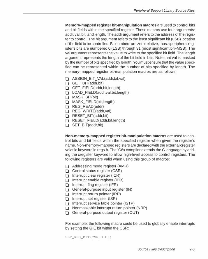
Memory-mapped register bit-manipulation macros are used to control bitsand bit fields within the specified register. These macros use four arguments:addr, val, bit, and length. The addr argument refers to the address of the regis-ter to control. The bit argument refers to the least significant bit (LSB) locationof the field to be controlled. Bit numbers are zero relative, thus a peripheral reg-ister’s bits are numbered 0 (LSB) through 31 (most significant bit–MSB). Theval argument represents the value to write to the specified bit field. The lengthargument represents the length of the bit field in bits. Note that val is maskedby the number of bits specified by length. You must ensure that the value speci-fied can be represented within the number of bits specified by length. Thememory-mapped register bit-manipulation macros are as follows:
� ASSIGN_BIT_VAL(addr,bit,val)� GET_BIT(addr,bit)� GET_FIELD(addr,bit,length)� LOAD_FIELD(addr,val,bit,length)� MASK_BIT(bit)� MASK_FIELD(bit,length)� REG_READ(addr)� REG_WRITE(addr,val)� RESET_BIT(addr,bit)� RESET_FIELD(addr,bit,length)� SET_BIT(addr,bit)
Non-memory-mapped register bit-manipulation macros are used to con-trol bits and bit fields within the specified register when given the register’sname. Non-memory-mapped registers are declared with the external cregistervolatile keyword in regs.h. The ’C6x compiler extends the C language by add-ing the cregister keyword to allow high-level access to control registers. Thefollowing registers are valid when using this group of macros:
� Addressing mode register (AMR)� Control status register (CSR)� Interrupt clear register (ICR)� Interrupt enable register (IER)� Interrupt flag register (IFR)� General-purpose input register (IN)� Interrupt return pointer (IRP)� Interrupt set register (ISR)� Interrupt service table pointer (ISTP)� Nonmaskable interrupt return pointer (NRP)� General-purpose output register (OUT)
For example, the following macro could be used to globally enable interruptsby setting the GIE bit within the CSR:
SET_REG_BIT(CSR,GIE);
Peripheral Support Library Source Files
2-4
The list of memory-mapped register bit-manipulation macros is shown below:
� GET_REG(reg)� GET_REG_BIT(reg,bit)� GET_REG_FIELD(reg,bit,length)� LOAD_REG_FIELD(reg,val,bit,length)� RESET_REG_BIT(reg,bit)� SET_REG(reg,val)� SET_REG_BIT(reg,bit)
Often, macros for other peripherals accomplish the same operations per-formed by the macros in regs.h. For instance, the intr.h header file defines themacro INTR_GLOBAL_ENABLE, which also sets the GIE bit in the CSR butrequires no arguments. The regs.h file is the lowest-level include file and isused by the peripheral-specific include files. In fact, the macro INTR_GLOBAL_ENABLE is defined in intr.h as follows:
#define INTR_GLOBAL_ENABLE SET_REG_BIT(CSR, GIE)
Although these two methods of setting the GIE bit are exactly the same, useof the higher-level macro INTR_GLOBAL_ENABLE improves code readabilityand demonstrates why you should use these higher-level macros when theyare available.
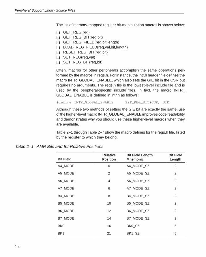
Table 2–1 through Table 2–7 show the macro defines for the regs.h file, listedby the register to which they belong.
Table 2–1. AMR Bits and Bit-Relative Positions
Bit FieldRelativePosition
Bit Field LengthMnemonic
Bit FieldLength
A4_MODE 0 A4_MODE_SZ 2
A5_MODE 2 A5_MODE_SZ 2
A6_MODE 4 A6_MODE_SZ 2
A7_MODE 6 A7_MODE_SZ 2
B4_MODE 8 B4_MODE_SZ 2
B5_MODE 10 B5_MODE_SZ 2
B6_MODE 12 B6_MODE_SZ 2
B7_MODE 14 B7_MODE_SZ 2
BK0 16 BK0_SZ 5
BK1 21 BK1_SZ 5
Peripheral Support Library Source Files
2-5 Source Files Description
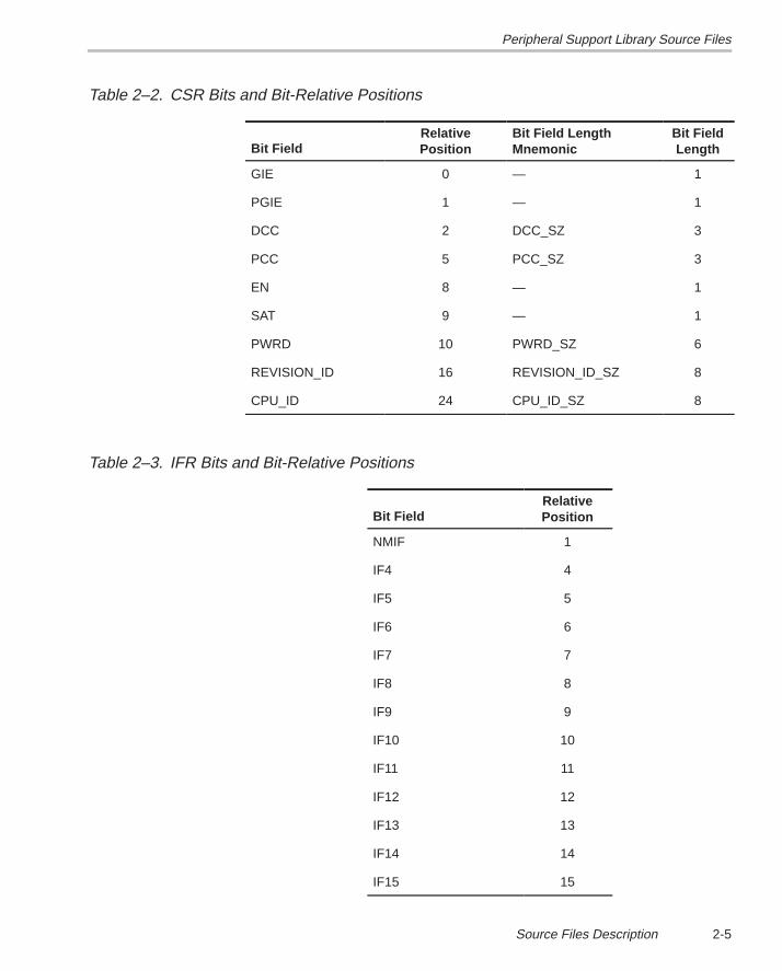
Table 2–2. CSR Bits and Bit-Relative Positions
Bit FieldRelativePosition
Bit Field LengthMnemonic
Bit FieldLength
GIE 0 — 1
PGIE 1 — 1
DCC 2 DCC_SZ 3
PCC 5 PCC_SZ 3
EN 8 — 1
SAT 9 — 1
PWRD 10 PWRD_SZ 6
REVISION_ID 16 REVISION_ID_SZ 8
CPU_ID 24 CPU_ID_SZ 8
Table 2–3. IFR Bits and Bit-Relative Positions
Bit FieldRelativePosition
NMIF 1
IF4 4
IF5 5
IF6 6
IF7 7
IF8 8
IF9 9
IF10 10
IF11 11
IF12 12
IF13 13
IF14 14
IF15 15
Peripheral Support Library Source Files
2-6
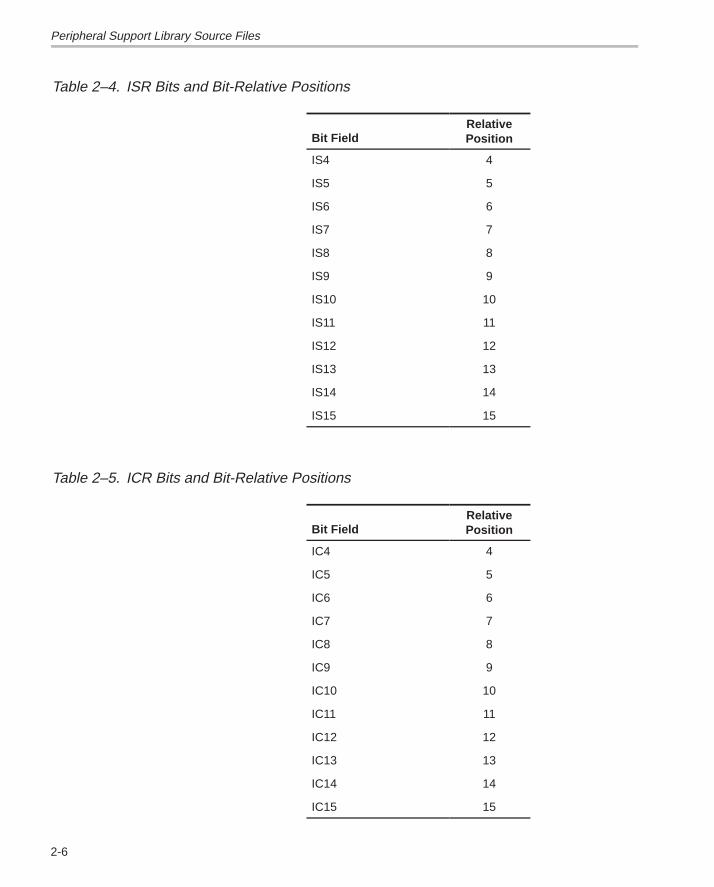
Table 2–4. ISR Bits and Bit-Relative Positions
Bit FieldRelativePosition
IS4 4
IS5 5
IS6 6
IS7 7
IS8 8
IS9 9
IS10 10
IS11 11
IS12 12
IS13 13
IS14 14
IS15 15
Table 2–5. ICR Bits and Bit-Relative Positions
Bit FieldRelativePosition
IC4 4
IC5 5
IC6 6
IC7 7
IC8 8
IC9 9
IC10 10
IC11 11
IC12 12
IC13 13
IC14 14
IC15 15
Peripheral Support Library Source Files
2-7 Source Files Description
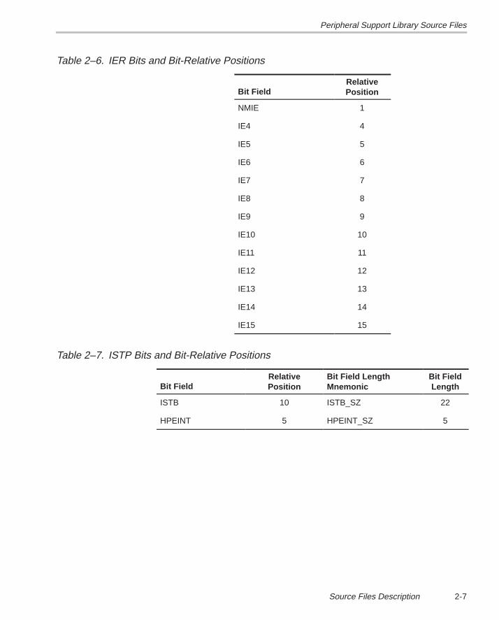
Table 2–6. IER Bits and Bit-Relative Positions
Bit FieldRelativePosition
NMIE 1
IE4 4
IE5 5
IE6 6
IE7 7
IE8 8
IE9 9
IE10 10
IE11 11
IE12 12
IE13 13
IE14 14
IE15 15
Table 2–7. ISTP Bits and Bit-Relative Positions
Bit FieldRelativePosition
Bit Field LengthMnemonic
Bit FieldLength
ISTB 10 ISTB_SZ 22
HPEINT 5 HPEINT_SZ 5
Peripheral Support Library Source Files
2-8
The following examples show the use of macros, functions, and defines in thedevice register support header file:
Example 1 : The following code reads the revision ID field of the CSR to deter-mine the revision ID of the ’C6x on which the code is currently running:
unsigned int revision_id;
revision_id=GET_REG_FIELD(CSR,REVISION_ID,REVISION_ID_SZ);
Example 2 : The following macro generates the INT4 interrupt and sets thecorresponding bit in the ISR:
SET_REG_BIT(ISR,IS4);
Example 3 : The following code reads the current value of the timer 0 counterregister:
unsigned int count_val;
count_val = REG_READ(TIMER_COUNTER_ADDR(0));
Note that the macro function TIMER_COUNTER_ADDR(chan), which returnsthe address of the indicated timer counter register, is supplied in the timer.hfile. This file must be included for this code to work.
2.2.2 Cache Support (cache.h)
The cache.h file provides macro functions for controlling the mode of the inter-nal program memory of the ‘C6x. These macros manipulate the programcache control (PCC) field of the CPU CSR. There are no arguments to any ofthese macro functions. The following is a list of the macros supplied in cache.h:
� CACHE_BYPASS( )� CACHE_DISABLE( )� CACHE_ENABLE( )� CACHE_FLUSH( )� CACHE_FREEZE( )� IDLE( )
The following examples show the use of macros, functions, and defines in thecache support header file:
Example 1: The following call enables the internal program memory as pro-gram cache:
CACHE_ENABLE( );
Example 2: The following call returns the program memory area to mappedmode:
CACHE_DISABLE( );
Peripheral Support Library Source Files
2-9 Source Files Description
2.2.3 Direct Memory Access Support (dma.h, dma.c)
The dma.h and dma.c files provide macros and functions that control the op-eration of the ‘C6x DMA controller. Functions are provided in dma.c (as wellas their corresponding inline functions in dma.h) to initialize and reset all chan-nels of the DMA controller. Control macros are provided in dma.h that start op-eration in normal and autoinitialization modes, pause, and stop the indicatedDMA channel. These functions and macros are listed below:
The reset and initialization functions are as follows:
� dma_global_init(auxcr,gcra,gcrb,gndxa,gndxb,gaddra,gaddrb,gaddrc,gaddrd)
� dma_init(channel,pri_ctrl,sec_ctrl,src_addr,dst_addr,trans_ctr)
� dma_reset( )
Operation mode macros are as follows:
� DMA_AUTO_START(chan)� DMA_PAUSE(chan)� DMA_RSYNC_CLR(chan)� DMA_RSYNC_SET(chan)� DMA_START(chan)� DMA_STOP(chan)� DMA_WSYNC_CLR(chan)� DMA_WSYNC_SET(chan)
The dma.h file also provides a number of macros that may be used to obtainthe memory-mapped address of a DMA register, based upon a given channelnumber. These macros are:
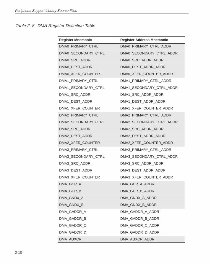
� DMA_DEST_ADDR_ADDR(chan)� DMA_PRIMARY_CTRL_ADDR(chan)� DMA_SECONDARY_CTRL_ADDR(chan)� DMA_SRC_ADDR_ADDR(chan)� DMA_XFER_COUNTER_ADDR(chan)
Table 2–8 shows the DMA register definition table.
Peripheral Support Library Source Files
2-10
Table 2–8. DMA Register Definition Table
Register Mnemonic Register Address Mnemonic
DMA0_PRIMARY_CTRL DMA0_PRIMARY_CTRL_ADDR
DMA0_SECONDARY_CTRL DMA0_SECONDARY_CTRL_ADDR
DMA0_SRC_ADDR DMA0_SRC_ADDR_ADDR
DMA0_DEST_ADDR DMA0_DEST_ADDR_ADDR
DMA0_XFER_COUNTER DMA0_XFER_COUNTER_ADDR
DMA1_PRIMARY_CTRL DMA1_PRIMARY_CTRL_ADDR
DMA1_SECONDARY_CTRL DMA1_SECONDARY_CTRL_ADDR
DMA1_SRC_ADDR DMA1_SRC_ADDR_ADDR
DMA1_DEST_ADDR DMA1_DEST_ADDR_ADDR
DMA1_XFER_COUNTER DMA1_XFER_COUNTER_ADDR
DMA2_PRIMARY_CTRL DMA2_PRIMARY_CTRL_ADDR
DMA2_SECONDARY_CTRL DMA2_SECONDARY_CTRL_ADDR
DMA2_SRC_ADDR DMA2_SRC_ADDR_ADDR
DMA2_DEST_ADDR DMA2_DEST_ADDR_ADDR
DMA2_XFER_COUNTER DMA2_XFER_COUNTER_ADDR
DMA3_PRIMARY_CTRL DMA3_PRIMARY_CTRL_ADDR
DMA3_SECONDARY_CTRL DMA3_SECONDARY_CTRL_ADDR
DMA3_SRC_ADDR DMA3_SRC_ADDR_ADDR
DMA3_DEST_ADDR DMA3_DEST_ADDR_ADDR
DMA3_XFER_COUNTER DMA3_XFER_COUNTER_ADDR
DMA_GCR_A DMA_GCR_A_ADDR
DMA_GCR_B DMA_GCR_B_ADDR
DMA_GNDX_A DMA_GNDX_A_ADDR
DMA_GNDX_B DMA_GNDX_B_ADDR
DMA_GADDR_A DMA_GADDR_A_ADDR
DMA_GADDR_B DMA_GADDR_B_ADDR
DMA_GADDR_C DMA_GADDR_C_ADDR
DMA_GADDR_D DMA_GADDR_D_ADDR
DMA_AUXCR DMA_AUXCR_ADDR
Peripheral Support Library Source Files
2-11 Source Files Description
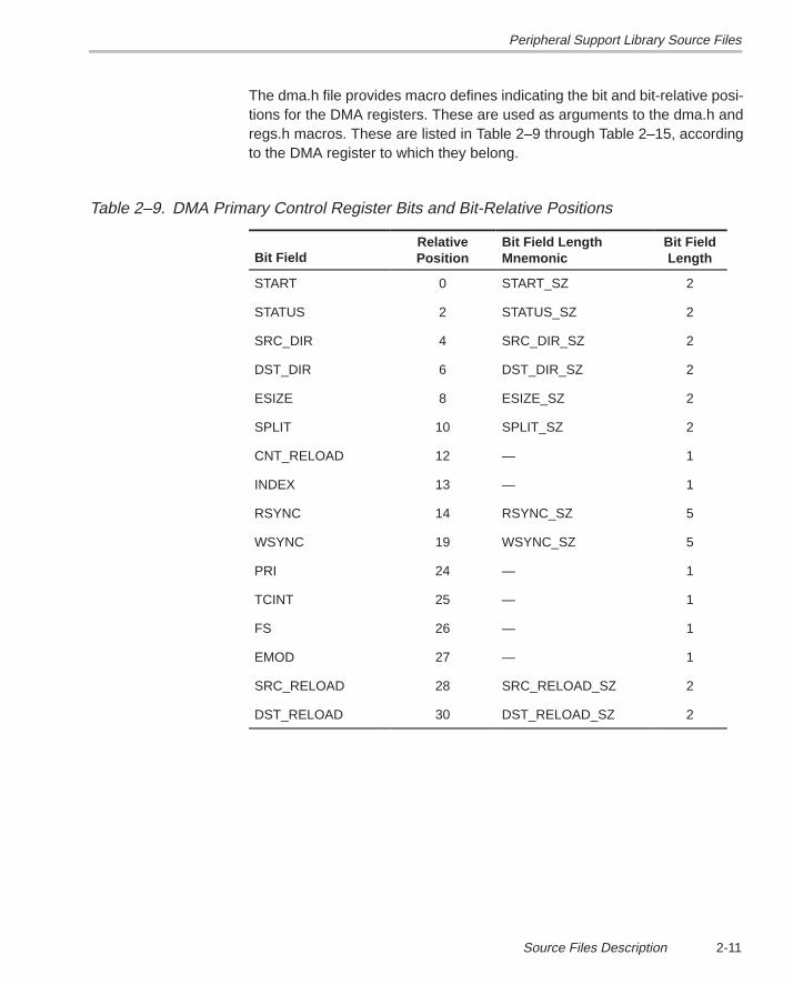
The dma.h file provides macro defines indicating the bit and bit-relative posi-tions for the DMA registers. These are used as arguments to the dma.h andregs.h macros. These are listed in Table 2–9 through Table 2–15, accordingto the DMA register to which they belong.
Table 2–9. DMA Primary Control Register Bits and Bit-Relative Positions
Bit FieldRelativePosition
Bit Field LengthMnemonic
Bit FieldLength
START 0 START_SZ 2
STATUS 2 STATUS_SZ 2
SRC_DIR 4 SRC_DIR_SZ 2
DST_DIR 6 DST_DIR_SZ 2
ESIZE 8 ESIZE_SZ 2
SPLIT 10 SPLIT_SZ 2
CNT_RELOAD 12 — 1
INDEX 13 — 1
RSYNC 14 RSYNC_SZ 5
WSYNC 19 WSYNC_SZ 5
PRI 24 — 1
TCINT 25 — 1
FS 26 — 1
EMOD 27 — 1
SRC_RELOAD 28 SRC_RELOAD_SZ 2
DST_RELOAD 30 DST_RELOAD_SZ 2
Peripheral Support Library Source Files
2-12
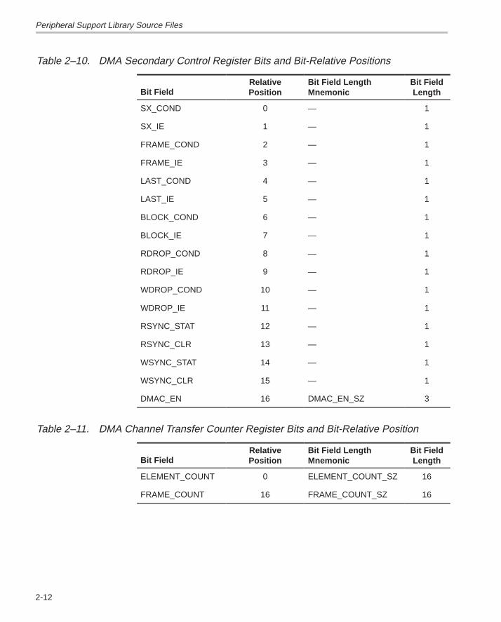
Table 2–10. DMA Secondary Control Register Bits and Bit-Relative Positions
Bit FieldRelativePosition
Bit Field LengthMnemonic
Bit FieldLength
SX_COND 0 — 1
SX_IE 1 — 1
FRAME_COND 2 — 1
FRAME_IE 3 — 1
LAST_COND 4 — 1
LAST_IE 5 — 1
BLOCK_COND 6 — 1
BLOCK_IE 7 — 1
RDROP_COND 8 — 1
RDROP_IE 9 — 1
WDROP_COND 10 — 1
WDROP_IE 11 — 1
RSYNC_STAT 12 — 1
RSYNC_CLR 13 — 1
WSYNC_STAT 14 — 1
WSYNC_CLR 15 — 1
DMAC_EN 16 DMAC_EN_SZ 3
Table 2–11. DMA Channel Transfer Counter Register Bits and Bit-Relative Position
Bit FieldRelativePosition
Bit Field LengthMnemonic
Bit FieldLength
ELEMENT_COUNT 0 ELEMENT_COUNT_SZ 16
FRAME_COUNT 16 FRAME_COUNT_SZ 16
Peripheral Support Library Source Files
2-13 Source Files Description
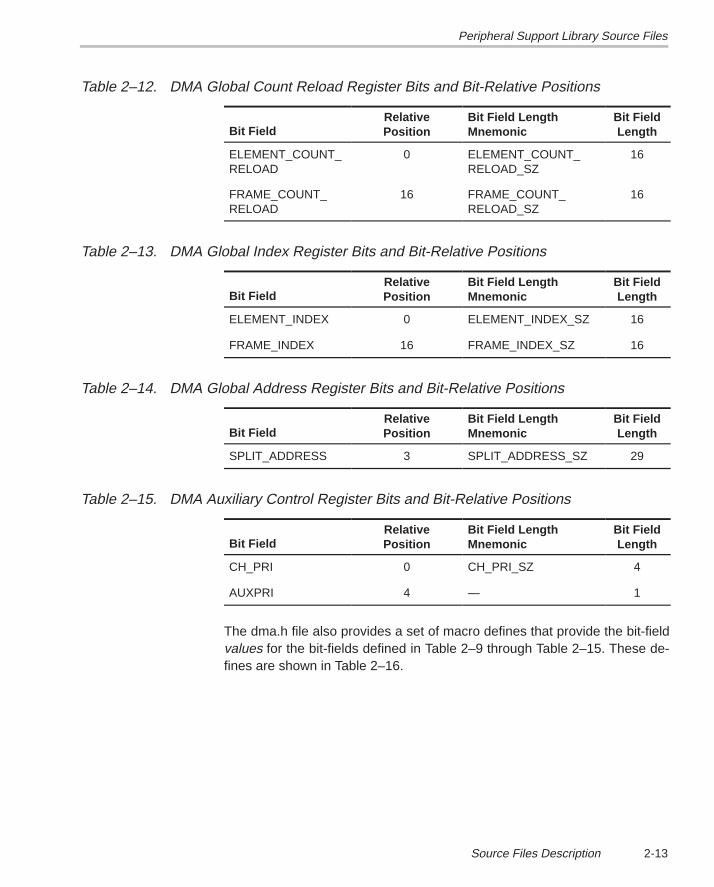
Table 2–12. DMA Global Count Reload Register Bits and Bit-Relative Positions
Bit FieldRelativePosition
Bit Field LengthMnemonic
Bit FieldLength
ELEMENT_COUNT_RELOAD
0 ELEMENT_COUNT_RELOAD_SZ
16
FRAME_COUNT_RELOAD
16 FRAME_COUNT_RELOAD_SZ
16
Table 2–13. DMA Global Index Register Bits and Bit-Relative Positions
Bit FieldRelativePosition
Bit Field LengthMnemonic
Bit FieldLength
ELEMENT_INDEX 0 ELEMENT_INDEX_SZ 16
FRAME_INDEX 16 FRAME_INDEX_SZ 16
Table 2–14. DMA Global Address Register Bits and Bit-Relative Positions
Bit FieldRelativePosition
Bit Field LengthMnemonic
Bit FieldLength
SPLIT_ADDRESS 3 SPLIT_ADDRESS_SZ 29
Table 2–15. DMA Auxiliary Control Register Bits and Bit-Relative Positions
Bit FieldRelativePosition
Bit Field LengthMnemonic
Bit FieldLength
CH_PRI 0 CH_PRI_SZ 4
AUXPRI 4 — 1
The dma.h file also provides a set of macro defines that provide the bit-fieldvalues for the bit-fields defined in Table 2–9 through Table 2–15. These de-fines are shown in Table 2–16.
Peripheral Support Library Source Files
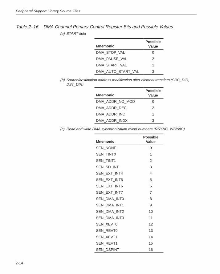
2-14
Table 2–16. DMA Channel Primary Control Register Bits and Possible Values(a) START field
MnemonicPossible
Value
DMA_STOP_VAL 0
DMA_PAUSE_VAL 2
DMA_START_VAL 1
DMA_AUTO_START_VAL 3
(b) Source/destination address modification after element transfers (SRC_DIR,DST_DIR)
MnemonicPossible
Value
DMA_ADDR_NO_MOD 0
DMA_ADDR_DEC 2
DMA_ADDR_INC 1
DMA_ADDR_INDX 3
(c) Read and write DMA synchronization event numbers (RSYNC, WSYNC)
MnemonicPossible
Value
SEN_NONE 0
SEN_TINT0 1
SEN_TINT1 2
SEN_SD_INT 3
SEN_EXT_INT4 4
SEN_EXT_INT5 5
SEN_EXT_INT6 6
SEN_EXT_INT7 7
SEN_DMA_INT0 8
SEN_DMA_INT1 9
SEN_DMA_INT2 10
SEN_DMA_INT3 11
SEN_XEVT0 12
SEN_REVT0 13
SEN_XEVT1 14
SEN_REVT1 15
SEN_DSPINT 16
Peripheral Support Library Source Files
2-15 Source Files Description
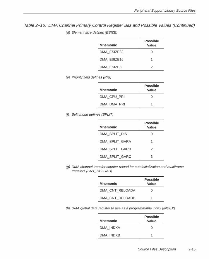
Table 2–16. DMA Channel Primary Control Register Bits and Possible Values (Continued)
(d) Element size defines (ESIZE)
MnemonicPossible
Value
DMA_ESIZE32 0
DMA_ESIZE16 1
DMA_ESIZE8 2
(e) Priority field defines (PRI)
MnemonicPossible
Value
DMA_CPU_PRI 0
DMA_DMA_PRI 1
(f) Split mode defines (SPLIT)
MnemonicPossible
Value
DMA_SPLIT_DIS 0
DMA_SPLIT_GARA 1
DMA_SPLIT_GARB 2
DMA_SPLIT_GARC 3
(g) DMA channel transfer counter reload for autoinitialization and multiframetransfers (CNT_RELOAD)
MnemonicPossible
Value
DMA_CNT_RELOADA 0
DMA_CNT_RELOADB 1
(h) DMA global data register to use as a programmable index (INDEX)
MnemonicPossible
Value
DMA_INDXA 0
DMA_INDXB 1
Peripheral Support Library Source Files
2-16
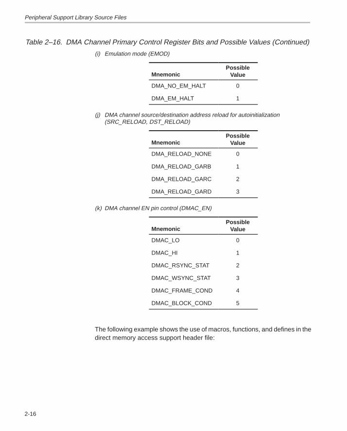
Table 2–16. DMA Channel Primary Control Register Bits and Possible Values (Continued)
(i) Emulation mode (EMOD)
MnemonicPossible
Value
DMA_NO_EM_HALT 0
DMA_EM_HALT 1
(j) DMA channel source/destination address reload for autoinitialization(SRC_RELOAD, DST_RELOAD)
MnemonicPossible
Value
DMA_RELOAD_NONE 0
DMA_RELOAD_GARB 1
DMA_RELOAD_GARC 2
DMA_RELOAD_GARD 3
(k) DMA channel EN pin control (DMAC_EN)
MnemonicPossible
Value
DMAC_LO 0
DMAC_HI 1
DMAC_RSYNC_STAT 2
DMAC_WSYNC_STAT 3
DMAC_FRAME_COND 4
DMAC_BLOCK_COND 5
The following example shows the use of macros, functions, and defines in thedirect memory access support header file:
Peripheral Support Library Source Files
2-17 Source Files Description
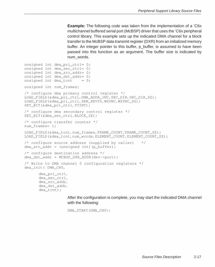
Example: The following code was taken from the implementation of a ’C6xmultichannel buffered serial port (McBSP) driver that uses the ’C6x peripheralcontrol library. This example sets up the indicated DMA channel for a blocktransfer to the McBSP data transmit register (DXR) from an initialized memorybuffer. An integer pointer to this buffer, p_buffer, is assumed to have beenpassed into this function as an argument. The buffer size is indicated bynum_words.
unsigned int dma_pri_ctrl= 0;unsigned int dma_sec_ctrl= 0;unsigned int dma_src_addr= 0;unsigned int dma_dst_addr= 0;unsigned int dma_tcnt = 0;
unsigned int num_frames;
/* configure dma primary control register */LOAD_FIELD(&dma_pri_ctrl,DMA_ADDR_INC,SRC_DIR,SRC_DIR_SZ);LOAD_FIELD(&dma_pri_ctrl,SEN_XEVT0,WSYNC,WSYNC_SZ);SET_BIT(&dma_pri_ctrl,TCINT);
/* configure dma secondary control register */SET_BIT(&dma_sec_ctrl,BLOCK_IE);
/* configure transfer counter */num_frames= 1;
LOAD_FIELD(&dma_tcnt,num_frames,FRAME_COUNT,FRAME_COUNT_SZ);LOAD_FIELD(&dma_tcnt,num_words,ELEMENT_COUNT,ELEMENT_COUNT_SZ);
/* configure source address (supplied by caller) */dma_src_addr = (unsigned int)(p_buffer);
/* configure destination address */dma_dst_addr = MCBSP_DXR_ADDR(dev–>port);
/* Write to DMA channel 0 configuration registers */dma_init( DMA_CH0,
dma_pri_ctrl,dma_sec_ctrl,dma_src_addr,dma_dst_addr,dma_tcnt);
After the configuration is complete, you may start the indicated DMA channelwith the following:
DMA_START(DMA_CH0);
Peripheral Support Library Source Files
2-18
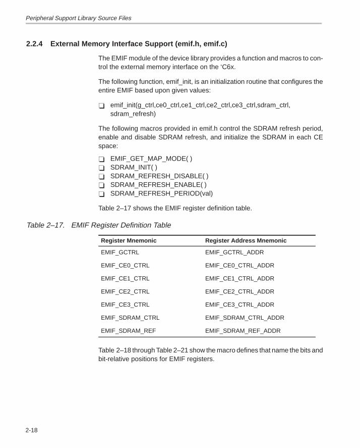
2.2.4 External Memory Interface Support (emif.h, emif.c)
The EMIF module of the device library provides a function and macros to con-trol the external memory interface on the ‘C6x.
The following function, emif_init, is an initialization routine that configures theentire EMIF based upon given values:
� emif_init(g_ctrl,ce0_ctrl,ce1_ctrl,ce2_ctrl,ce3_ctrl,sdram_ctrl,sdram_refresh)
The following macros provided in emif.h control the SDRAM refresh period,enable and disable SDRAM refresh, and initialize the SDRAM in each CEspace:
� EMIF_GET_MAP_MODE( )� SDRAM_INIT( )� SDRAM_REFRESH_DISABLE( )� SDRAM_REFRESH_ENABLE( )� SDRAM_REFRESH_PERIOD(val)
Table 2–17 shows the EMIF register definition table.
Table 2–17. EMIF Register Definition Table
Register Mnemonic Register Address Mnemonic
EMIF_GCTRL EMIF_GCTRL_ADDR
EMIF_CE0_CTRL EMIF_CE0_CTRL_ADDR
EMIF_CE1_CTRL EMIF_CE1_CTRL_ADDR
EMIF_CE2_CTRL EMIF_CE2_CTRL_ADDR
EMIF_CE3_CTRL EMIF_CE3_CTRL_ADDR
EMIF_SDRAM_CTRL EMIF_SDRAM_CTRL_ADDR
EMIF_SDRAM_REF EMIF_SDRAM_REF_ADDR
Table 2–18 through Table 2–21 show the macro defines that name the bits andbit-relative positions for EMIF registers.
Peripheral Support Library Source Files
2-19 Source Files Description
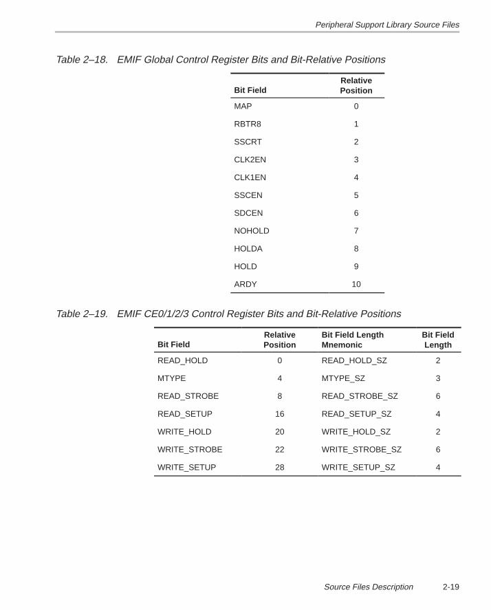
Table 2–18. EMIF Global Control Register Bits and Bit-Relative Positions
Bit FieldRelativePosition
MAP 0
RBTR8 1
SSCRT 2
CLK2EN 3
CLK1EN 4
SSCEN 5
SDCEN 6
NOHOLD 7
HOLDA 8
HOLD 9
ARDY 10
Table 2–19. EMIF CE0/1/2/3 Control Register Bits and Bit-Relative Positions
Bit FieldRelativePosition
Bit Field LengthMnemonic
Bit FieldLength
READ_HOLD 0 READ_HOLD_SZ 2
MTYPE 4 MTYPE_SZ 3
READ_STROBE 8 READ_STROBE_SZ 6
READ_SETUP 16 READ_SETUP_SZ 4
WRITE_HOLD 20 WRITE_HOLD_SZ 2
WRITE_STROBE 22 WRITE_STROBE_SZ 6
WRITE_SETUP 28 WRITE_SETUP_SZ 4
Peripheral Support Library Source Files
2-20
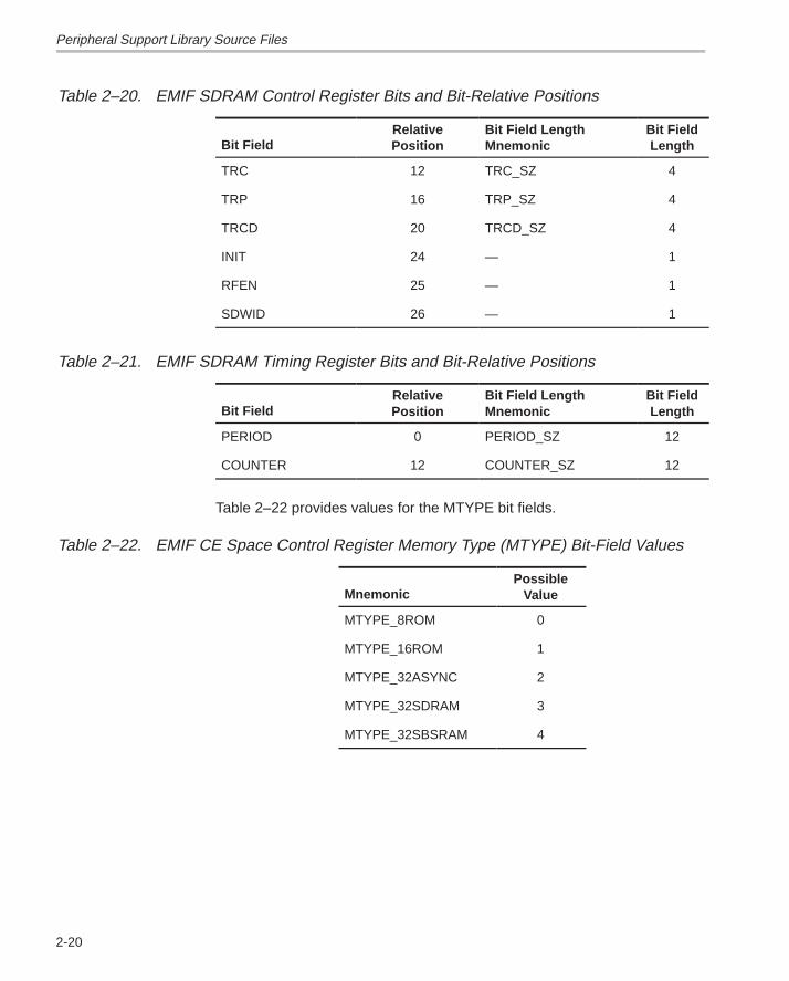
Table 2–20. EMIF SDRAM Control Register Bits and Bit-Relative Positions
Bit FieldRelativePosition
Bit Field LengthMnemonic
Bit FieldLength
TRC 12 TRC_SZ 4
TRP 16 TRP_SZ 4
TRCD 20 TRCD_SZ 4
INIT 24 — 1
RFEN 25 — 1
SDWID 26 — 1
Table 2–21. EMIF SDRAM Timing Register Bits and Bit-Relative Positions
Bit FieldRelativePosition
Bit Field LengthMnemonic
Bit FieldLength
PERIOD 0 PERIOD_SZ 12
COUNTER 12 COUNTER_SZ 12
Table 2–22 provides values for the MTYPE bit fields.
Table 2–22. EMIF CE Space Control Register Memory Type (MTYPE) Bit-Field Values
MnemonicPossible
Value
MTYPE_8ROM 0
MTYPE_16ROM 1
MTYPE_32ASYNC 2
MTYPE_32SDRAM 3
MTYPE_32SBSRAM 4
Peripheral Support Library Source Files
2-21 Source Files Description
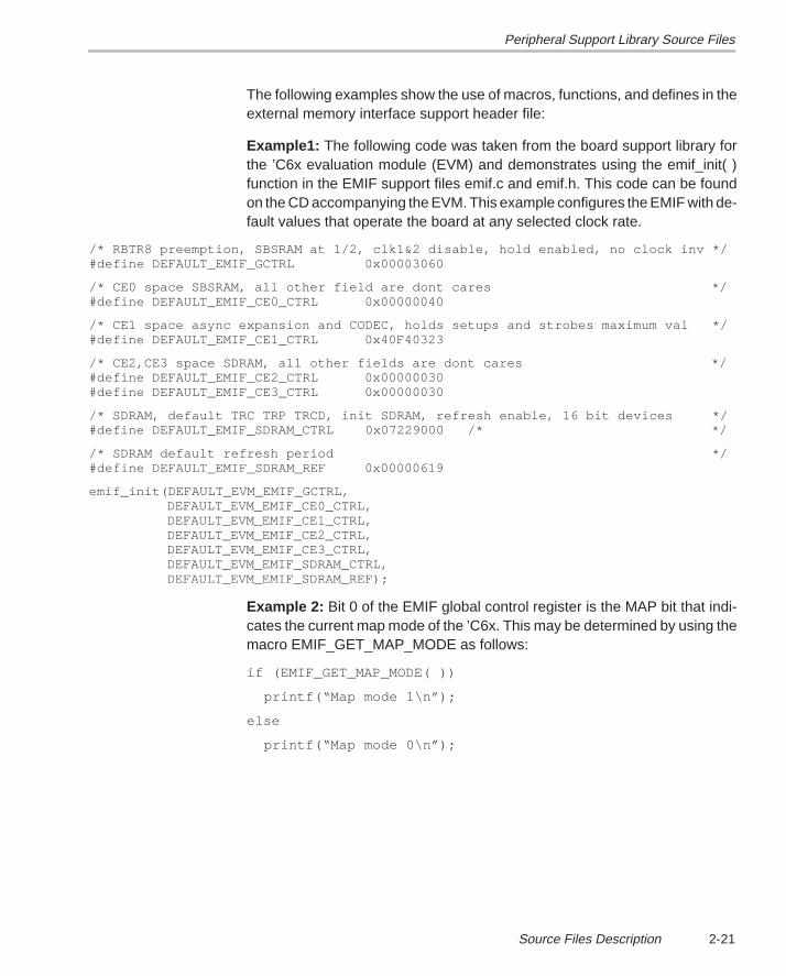
The following examples show the use of macros, functions, and defines in theexternal memory interface support header file:
Example1: The following code was taken from the board support library forthe ’C6x evaluation module (EVM) and demonstrates using the emif_init( )function in the EMIF support files emif.c and emif.h. This code can be foundon the CD accompanying the EVM. This example configures the EMIF with de-fault values that operate the board at any selected clock rate.
/* RBTR8 preemption, SBSRAM at 1/2, clk1&2 disable, hold enabled, no clock inv */#define DEFAULT_EMIF_GCTRL 0x00003060
/* CE0 space SBSRAM, all other field are dont cares */#define DEFAULT_EMIF_CE0_CTRL 0x00000040
/* CE1 space async expansion and CODEC, holds setups and strobes maximum val */#define DEFAULT_EMIF_CE1_CTRL 0x40F40323
/* CE2,CE3 space SDRAM, all other fields are dont cares */#define DEFAULT_EMIF_CE2_CTRL 0x00000030#define DEFAULT_EMIF_CE3_CTRL 0x00000030
/* SDRAM, default TRC TRP TRCD, init SDRAM, refresh enable, 16 bit devices */#define DEFAULT_EMIF_SDRAM_CTRL 0x07229000 /* */
/* SDRAM default refresh period */#define DEFAULT_EMIF_SDRAM_REF 0x00000619
emif_init(DEFAULT_EVM_EMIF_GCTRL, DEFAULT_EVM_EMIF_CE0_CTRL, DEFAULT_EVM_EMIF_CE1_CTRL, DEFAULT_EVM_EMIF_CE2_CTRL, DEFAULT_EVM_EMIF_CE3_CTRL, DEFAULT_EVM_EMIF_SDRAM_CTRL, DEFAULT_EVM_EMIF_SDRAM_REF);
Example 2: Bit 0 of the EMIF global control register is the MAP bit that indi-cates the current map mode of the ’C6x. This may be determined by using themacro EMIF_GET_MAP_MODE as follows:
if (EMIF_GET_MAP_MODE( ))
printf(“Map mode 1\n”);
else
printf(“Map mode 0\n”);
Peripheral Support Library Source Files
2-22
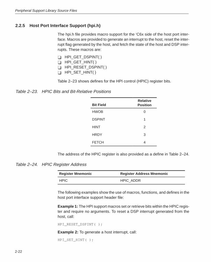
2.2.5 Host Port Interface Support (hpi.h)
The hpi.h file provides macro support for the ‘C6x side of the host port inter-face. Macros are provided to generate an interrupt to the host, reset the inter-rupt flag generated by the host, and fetch the state of the host and DSP inter-rupts. These macros are:
� HPI_GET_DSPINT( )� HPI_GET_HINT( )� HPI_RESET_DSPINT( )� HPI_SET_HINT( )
Table 2–23 shows defines for the HPI control (HPIC) register bits.
Table 2–23. HPIC Bits and Bit-Relative Positions
Bit FieldRelativePosition
HWOB 0
DSPINT 1
HINT 2
HRDY 3
FETCH 4
The address of the HPIC register is also provided as a define in Table 2–24.
Table 2–24. HPIC Register Address
Register Mnemonic Register Address Mnemonic
HPIC HPIC_ADDR
The following examples show the use of macros, functions, and defines in thehost port interface support header file:
Example 1: The HPI support macros set or retrieve bits within the HPIC regis-ter and require no arguments. To reset a DSP interrupt generated from thehost, call:
HPI_RESET_DSPINT( );
Example 2: To generate a host interrupt, call:
HPI_SET_HINT( );
Peripheral Support Library Source Files
2-23 Source Files Description
2.2.6 Interrupt Support (intr.h, intr.c, intr_.asm)
The interrupt module, which consists of the intr.h, intr.c, and intr_.asm files,provides support for interrupts on the ’C6x. The intr.h file contains defines forCPU interrupt numbers, interrupt selection numbers, and default interrupt se-lector values, as well as macro functions that manipulate interrupt-related bitswithin memory-mapped and non-memory-mapped registers.
The intr.c file provides subroutines that initialize interrupt processing, allow dy-namic interrupt hooking, and control the interrupt selector registers. Interruptprocessing is initialized by setting the interrupt service table pointer (ISTP) tothe address of the IST. The contents of the IST is provided in intr_.asm and itslocation in memory is determined by the linker command file. Each interruptservice fetch packet (ISFP) contains code that looks up the address of its cor-responding ISR from the isr_jump_table, which is defined in intr.c. If this loca-tion is “unhooked” (indicated by a value of 0), no ISR is called and the ISFPsimply returns from interrupt. If a non-zero value is found in the isr_jump_table,a branch to this location is executed. The intr_hook() routine is used to placethe address of an indicated ISR in the isr_jump_table at the location corre-sponding to the indicated CPU interrupt number.
Interrupt processing functions include the following:
� intr_get_cpu_intr(isn)� intr_hook(void(*fp)(void),cpu_intr)� intr_init( )� intr_isn(cpu_intr)� intr_map(cpu_intr,isn)� intr_reset()
The value *fp is a function pointer to the user supplied ISR, cpu_intr refers tothe CPU interrupt number, and isn refers to the interrupt selection number thatspecifies the interrupt source to map to a given CPU interrupt.
Peripheral Support Library Source Files
2-24
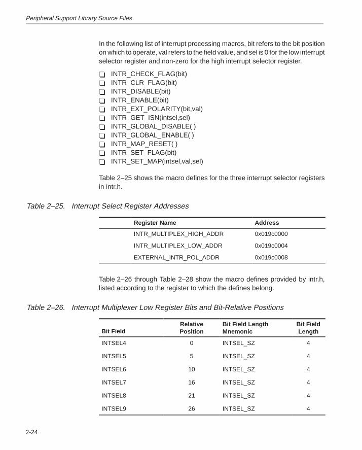
In the following list of interrupt processing macros, bit refers to the bit positionon which to operate, val refers to the field value, and sel is 0 for the low interruptselector register and non-zero for the high interrupt selector register.
� INTR_CHECK_FLAG(bit)� INTR_CLR_FLAG(bit)� INTR_DISABLE(bit)� INTR_ENABLE(bit)� INTR_EXT_POLARITY(bit,val)� INTR_GET_ISN(intsel,sel)� INTR_GLOBAL_DISABLE( )� INTR_GLOBAL_ENABLE( )� INTR_MAP_RESET( )� INTR_SET_FLAG(bit)� INTR_SET_MAP(intsel,val,sel)
Table 2–25 shows the macro defines for the three interrupt selector registersin intr.h.
Table 2–25. Interrupt Select Register Addresses
Register Name Address
INTR_MULTIPLEX_HIGH_ADDR 0x019c0000
INTR_MULTIPLEX_LOW_ADDR 0x019c0004
EXTERNAL_INTR_POL_ADDR 0x019c0008
Table 2–26 through Table 2–28 show the macro defines provided by intr.h,listed according to the register to which the defines belong.
Table 2–26. Interrupt Multiplexer Low Register Bits and Bit-Relative Positions
Bit FieldRelativePosition
Bit Field LengthMnemonic
Bit FieldLength
INTSEL4 0 INTSEL_SZ 4
INTSEL5 5 INTSEL_SZ 4
INTSEL6 10 INTSEL_SZ 4
INTSEL7 16 INTSEL_SZ 4
INTSEL8 21 INTSEL_SZ 4
INTSEL9 26 INTSEL_SZ 4
Peripheral Support Library Source Files
2-25 Source Files Description
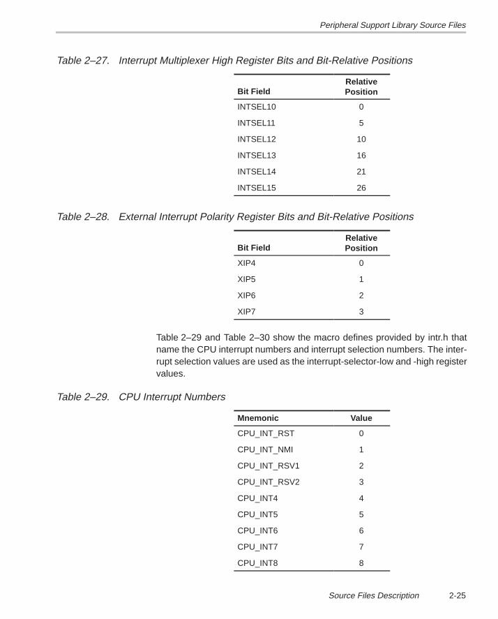
Table 2–27. Interrupt Multiplexer High Register Bits and Bit-Relative Positions
Bit FieldRelativePosition
INTSEL10 0
INTSEL11 5
INTSEL12 10
INTSEL13 16
INTSEL14 21
INTSEL15 26
Table 2–28. External Interrupt Polarity Register Bits and Bit-Relative Positions
Bit FieldRelativePosition
XIP4 0
XIP5 1
XIP6 2
XIP7 3
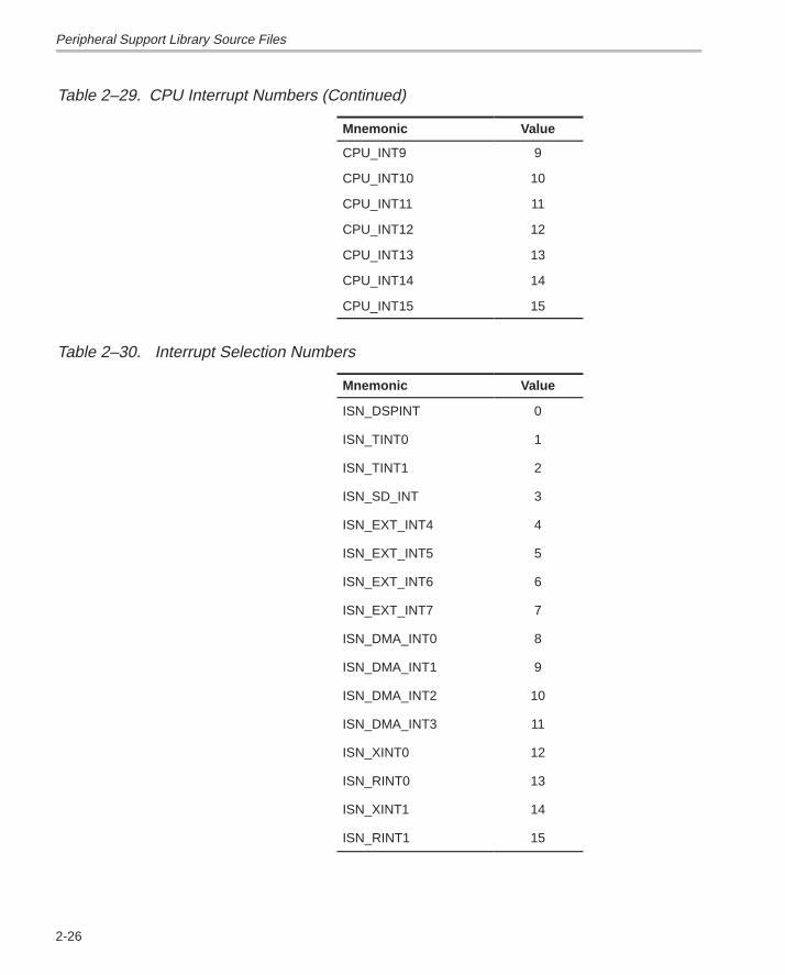
Table 2–29 and Table 2–30 show the macro defines provided by intr.h thatname the CPU interrupt numbers and interrupt selection numbers. The inter-rupt selection values are used as the interrupt-selector-low and -high registervalues.
Table 2–29. CPU Interrupt Numbers
Mnemonic Value
CPU_INT_RST 0
CPU_INT_NMI 1
CPU_INT_RSV1 2
CPU_INT_RSV2 3
CPU_INT4 4
CPU_INT5 5
CPU_INT6 6
CPU_INT7 7
CPU_INT8 8
Peripheral Support Library Source Files
2-26
Table 2–29. CPU Interrupt Numbers (Continued)
Mnemonic Value
CPU_INT9 9
CPU_INT10 10
CPU_INT11 11
CPU_INT12 12
CPU_INT13 13
CPU_INT14 14
CPU_INT15 15
Table 2–30. Interrupt Selection Numbers
Mnemonic Value
ISN_DSPINT 0
ISN_TINT0 1
ISN_TINT1 2
ISN_SD_INT 3
ISN_EXT_INT4 4
ISN_EXT_INT5 5
ISN_EXT_INT6 6
ISN_EXT_INT7 7
ISN_DMA_INT0 8
ISN_DMA_INT1 9
ISN_DMA_INT2 10
ISN_DMA_INT3 11
ISN_XINT0 12
ISN_RINT0 13
ISN_XINT1 14
ISN_RINT1 15
Peripheral Support Library Source Files
2-27 Source Files Description
The following examples show how an interrupt service routine (ISR) can behooked to a given interrupt.
Example 1: The interrupt source needs to be mapped to a CPU interrupt. Thisis accomplished by loading the interrupt selection number into the desired in-terrupt selection field in the interrupt multiplexer register (see theTMS320C6201/6701 Peripherals Reference Guide for more information). Tomap the DMA channel 0 interrupt source to CPU interrupt 8 (INT8), use theintr_map function as follows:
intr_map(CPU_INT8,ISN_DMA_INT0);
Example 2: Once the interrupt multiplexer register is configured, the ISR canbe hooked to the CPU interrupt and enabled as follows:
interrupt void exampleISR(void)
{
isrFlag= TRUE;
return;
}
intr_hook( exampleISR, CPU_INT8 );
INTR_ENABLE( CPU_INT8 );
A DMA channel 0 interrupt event now causes the example ISR to be invoked.
2.2.7 Multichannel Buffered Serial Port Support (mcbsp.h, mcbsp.c)
The mcbsp.h and mcbsp.c files contain macros and one function that controlthe multichannel buffered serial port registers on the ‘C6x. Four groups of mac-ros exist to control the operation of the indicated channel. The first group en-ables and disables functionality on the port. The second group is used to resetindicated portions of the McBSP. The third group is used during data transferto start, stop, and receive status of the indicated port. The fourth group of mac-ros returns the address of a particular McBSP register, based upon a given portnumber.
The McBSP enable and disable macros are as follows:
� MCBSP_ENABLE(port_no,type)� MCBSP_FRAME_SYNC_ENABLE(port_no)� MCBSP_IO_DISABLE(port_no)� MCBSP_IO_ENABLE(port_no)� MCBSP_LOOPBACK_DISABLE(port_no)� MCBSP_LOOPBACK_ENABLE(port_no)� MCBSP_SAMPLE_RATE_ENABLE(port_no)
Peripheral Support Library Source Files
2-28
McBSP reset and initialization macros and function are as follows:
� Macros:
� MCBSP_FRAME_SYNC_RESET(port_no)� MCBSP_RX_RESET(port_no)� MCBSP_SAMPLE_RATE_RESET(port_no)� MCBSP_TX_RESET(port_no)
� Function:
� mcbsp_init(port_no,spcr_ctrl,rcr_ctrl,xcr_ctrl,srgr_ctrl,mcr_ctrl,rcer_ctrl,xcer_ctrl,pcr_ctrl)
McBSP data transfer macros follow:
� MCBSP_ADDR(port_no)� MCBSP_BYTES_PER_WORD(wdlen)� MCBSP_READ(port_no)� MCBSP_RRDY(port_no)� MCBSP_WRITE(port_no)� MCBSP_XRDY(port_no)
McBSP register address macros are as follows:
� MCBSP_DRR_ADDR(port_no)� MCBSP_DXR_ADDR(port_no)� MCBSP_MCR_ADDR(port_no)� MCBSP_PCR_ADDR(port_no)� MCBSP_RCER_ADDR(port_no)� MCBSP_RCR_ADDR(port_no)� MCBSP_SPCR_ADDR(port_no)� MCBSP_SRGR_ADDR(port_no)� MCBSP_XCER_ADDR(port_no)� MCBSP_XCR_ADDR(port_no)
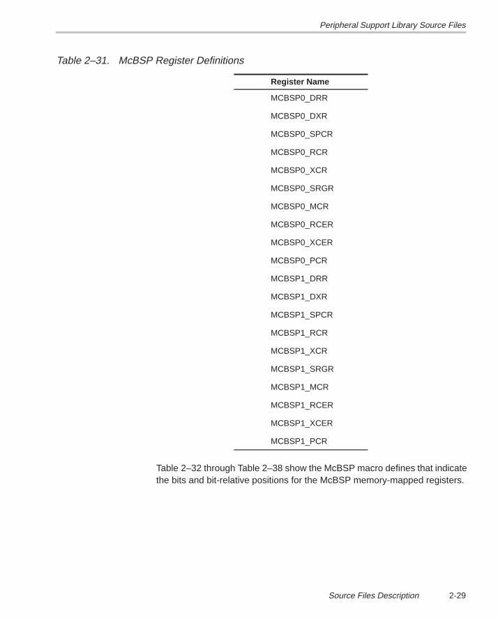
Table 2–31 shows the McBSP register definition table. McBSP register ad-dresses may be obtained by using the register address macros shown inTable 3–7 on page 3-6.
Peripheral Support Library Source Files
2-29 Source Files Description
Table 2–31. McBSP Register Definitions
Register Name
MCBSP0_DRR
MCBSP0_DXR
MCBSP0_SPCR
MCBSP0_RCR
MCBSP0_XCR
MCBSP0_SRGR
MCBSP0_MCR
MCBSP0_RCER
MCBSP0_XCER
MCBSP0_PCR
MCBSP1_DRR
MCBSP1_DXR
MCBSP1_SPCR
MCBSP1_RCR
MCBSP1_XCR
MCBSP1_SRGR
MCBSP1_MCR
MCBSP1_RCER
MCBSP1_XCER
MCBSP1_PCR
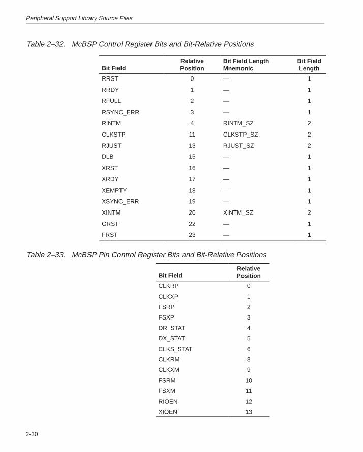
Table 2–32 through Table 2–38 show the McBSP macro defines that indicatethe bits and bit-relative positions for the McBSP memory-mapped registers.
Peripheral Support Library Source Files
2-30
Table 2–32. McBSP Control Register Bits and Bit-Relative Positions
Bit FieldRelativePosition
Bit Field LengthMnemonic
Bit FieldLength
RRST 0 — 1
RRDY 1 — 1
RFULL 2 — 1
RSYNC_ERR 3 — 1
RINTM 4 RINTM_SZ 2
CLKSTP 11 CLKSTP_SZ 2
RJUST 13 RJUST_SZ 2
DLB 15 — 1
XRST 16 — 1
XRDY 17 — 1
XEMPTY 18 — 1
XSYNC_ERR 19 — 1
XINTM 20 XINTM_SZ 2
GRST 22 — 1
FRST 23 — 1
Table 2–33. McBSP Pin Control Register Bits and Bit-Relative Positions
Bit FieldRelativePosition
CLKRP 0
CLKXP 1
FSRP 2
FSXP 3
DR_STAT 4
DX_STAT 5
CLKS_STAT 6
CLKRM 8
CLKXM 9
FSRM 10
FSXM 11
RIOEN 12
XIOEN 13
Peripheral Support Library Source Files
2-31 Source Files Description
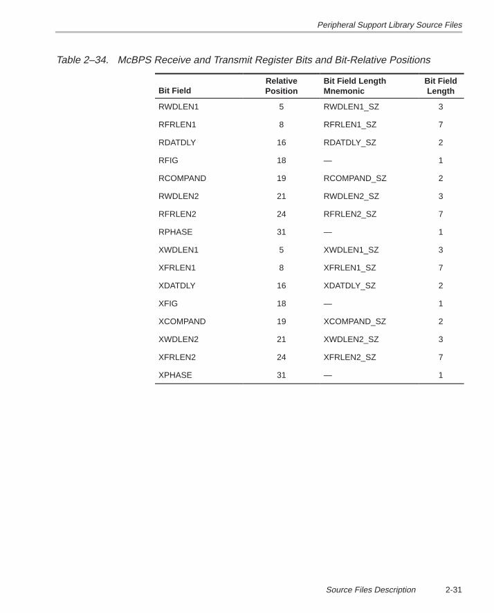
Table 2–34. McBPS Receive and Transmit Register Bits and Bit-Relative Positions
Bit FieldRelativePosition
Bit Field LengthMnemonic
Bit FieldLength
RWDLEN1 5 RWDLEN1_SZ 3
RFRLEN1 8 RFRLEN1_SZ 7
RDATDLY 16 RDATDLY_SZ 2
RFIG 18 — 1
RCOMPAND 19 RCOMPAND_SZ 2
RWDLEN2 21 RWDLEN2_SZ 3
RFRLEN2 24 RFRLEN2_SZ 7
RPHASE 31 — 1
XWDLEN1 5 XWDLEN1_SZ 3
XFRLEN1 8 XFRLEN1_SZ 7
XDATDLY 16 XDATDLY_SZ 2
XFIG 18 — 1
XCOMPAND 19 XCOMPAND_SZ 2
XWDLEN2 21 XWDLEN2_SZ 3
XFRLEN2 24 XFRLEN2_SZ 7
XPHASE 31 — 1
Peripheral Support Library Source Files
2-32
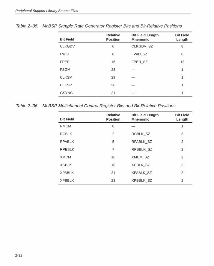
Table 2–35. McBSP Sample Rate Generator Register Bits and Bit-Relative Positions
Bit FieldRelativePosition
Bit Field LengthMnemonic
Bit FieldLength
CLKGDV 0 CLKGDV_SZ 8
FWID 8 FWID_SZ 8
FPER 16 FPER_SZ 12
FSGM 28 — 1
CLKSM 29 — 1
CLKSP 30 — 1
GSYNC 31 — 1
Table 2–36. McBSP Multichannel Control Register Bits and Bit-Relative Positions
Bit FieldRelativePosition
Bit Field LengthMnemonic
Bit FieldLength
RMCM 0 — 1
RCBLK 2 RCBLK_SZ 3
RPABLK 5 RPABLK_SZ 2
RPBBLK 7 RPBBLK_SZ 2
XMCM 16 XMCM_SZ 2
XCBLK 18 XCBLK_SZ 3
XPABLK 21 XPABLK_SZ 2
XPBBLK 23 XPBBLK_SZ 2
Peripheral Support Library Source Files
2-33 Source Files Description
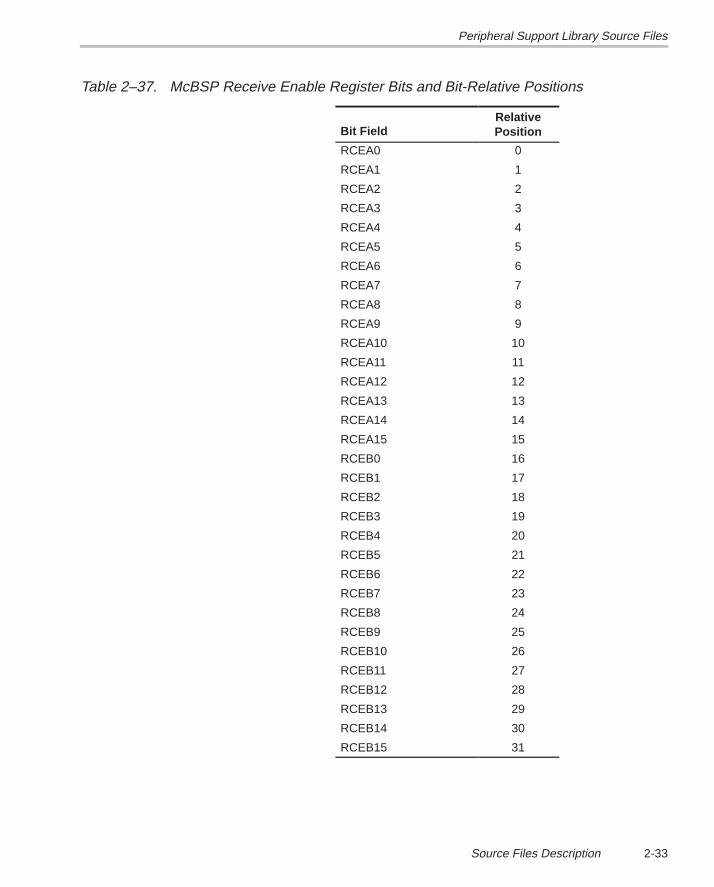
Table 2–37. McBSP Receive Enable Register Bits and Bit-Relative Positions
Bit FieldRelativePosition
RCEA0 0
RCEA1 1
RCEA2 2
RCEA3 3
RCEA4 4
RCEA5 5
RCEA6 6
RCEA7 7
RCEA8 8
RCEA9 9
RCEA10 10
RCEA11 11
RCEA12 12
RCEA13 13
RCEA14 14
RCEA15 15
RCEB0 16
RCEB1 17
RCEB2 18
RCEB3 19
RCEB4 20
RCEB5 21
RCEB6 22
RCEB7 23
RCEB8 24
RCEB9 25
RCEB10 26
RCEB11 27
RCEB12 28
RCEB13 29
RCEB14 30
RCEB15 31
Peripheral Support Library Source Files
2-34
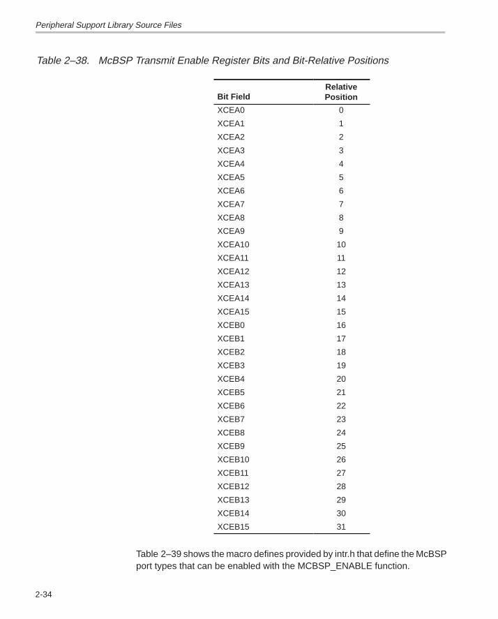
Table 2–38. McBSP Transmit Enable Register Bits and Bit-Relative Positions
Bit FieldRelativePosition
XCEA0 0
XCEA1 1
XCEA2 2
XCEA3 3
XCEA4 4
XCEA5 5
XCEA6 6
XCEA7 7
XCEA8 8
XCEA9 9
XCEA10 10
XCEA11 11
XCEA12 12
XCEA13 13
XCEA14 14
XCEA15 15
XCEB0 16
XCEB1 17
XCEB2 18
XCEB3 19
XCEB4 20
XCEB5 21
XCEB6 22
XCEB7 23
XCEB8 24
XCEB9 25
XCEB10 26
XCEB11 27
XCEB12 28
XCEB13 29
XCEB14 30
XCEB15 31
Table 2–39 shows the macro defines provided by intr.h that define the McBSPport types that can be enabled with the MCBSP_ENABLE function.
Peripheral Support Library Source Files
2-35 Source Files Description
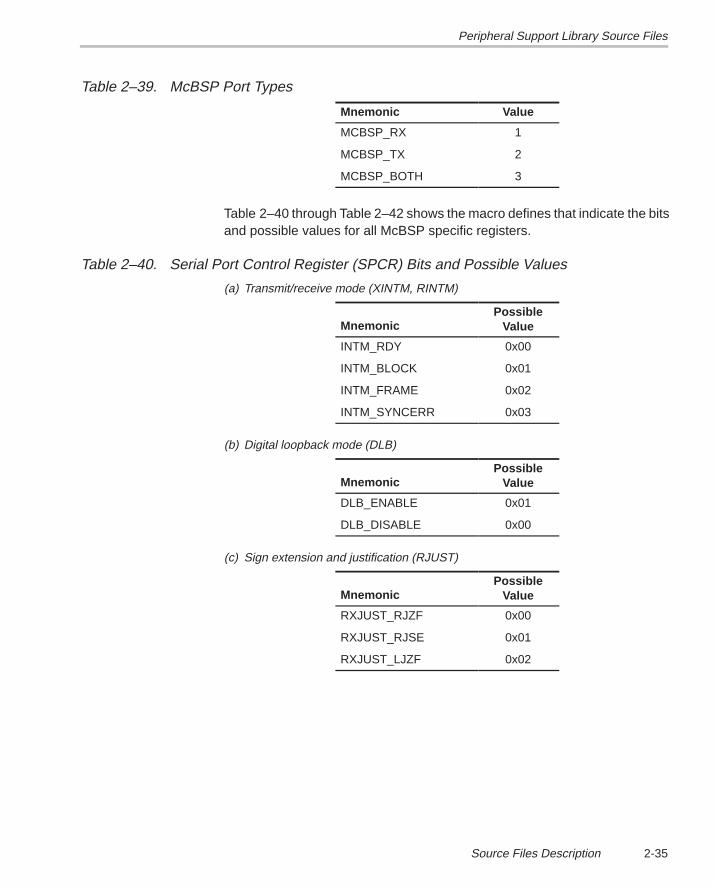
Table 2–39. McBSP Port Types
Mnemonic Value
MCBSP_RX 1
MCBSP_TX 2
MCBSP_BOTH 3
Table 2–40 through Table 2–42 shows the macro defines that indicate the bitsand possible values for all McBSP specific registers.
Table 2–40. Serial Port Control Register (SPCR) Bits and Possible Values
(a) Transmit/receive mode (XINTM, RINTM)
MnemonicPossible
Value
INTM_RDY 0x00
INTM_BLOCK 0x01
INTM_FRAME 0x02
INTM_SYNCERR 0x03
(b) Digital loopback mode (DLB)
MnemonicPossible
Value
DLB_ENABLE 0x01
DLB_DISABLE 0x00
(c) Sign extension and justification (RJUST)
MnemonicPossible
Value
RXJUST_RJZF 0x00
RXJUST_RJSE 0x01
RXJUST_LJZF 0x02
Peripheral Support Library Source Files
2-36
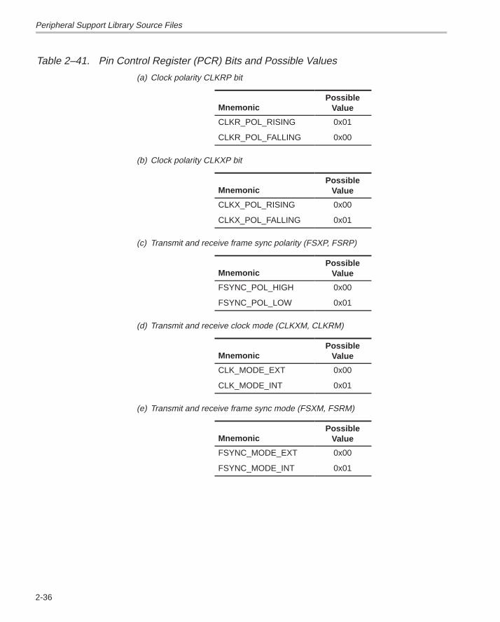
Table 2–41. Pin Control Register (PCR) Bits and Possible Values
(a) Clock polarity CLKRP bit
MnemonicPossible
Value
CLKR_POL_RISING 0x01
CLKR_POL_FALLING 0x00
(b) Clock polarity CLKXP bit
MnemonicPossible
Value
CLKX_POL_RISING 0x00
CLKX_POL_FALLING 0x01
(c) Transmit and receive frame sync polarity (FSXP, FSRP)
MnemonicPossible
Value
FSYNC_POL_HIGH 0x00
FSYNC_POL_LOW 0x01
(d) Transmit and receive clock mode (CLKXM, CLKRM)
MnemonicPossible
Value
CLK_MODE_EXT 0x00
CLK_MODE_INT 0x01
(e) Transmit and receive frame sync mode (FSXM, FSRM)
MnemonicPossible
Value
FSYNC_MODE_EXT 0x00
FSYNC_MODE_INT 0x01
Peripheral Support Library Source Files
2-37 Source Files Description
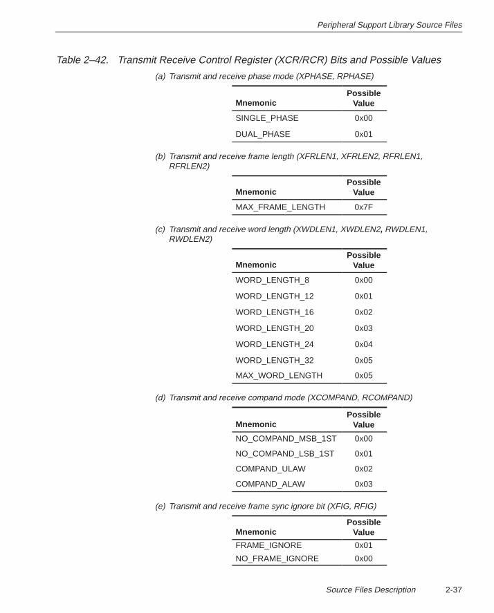
Table 2–42. Transmit Receive Control Register (XCR/RCR) Bits and Possible Values
(a) Transmit and receive phase mode (XPHASE, RPHASE)
MnemonicPossible
Value
SINGLE_PHASE 0x00
DUAL_PHASE 0x01
(b) Transmit and receive frame length (XFRLEN1, XFRLEN2, RFRLEN1,RFRLEN2)
MnemonicPossible
Value
MAX_FRAME_LENGTH 0x7F
(c) Transmit and receive word length (XWDLEN1, XWDLEN2, RWDLEN1,RWDLEN2)
MnemonicPossible
Value
WORD_LENGTH_8 0x00
WORD_LENGTH_12 0x01
WORD_LENGTH_16 0x02
WORD_LENGTH_20 0x03
WORD_LENGTH_24 0x04
WORD_LENGTH_32 0x05
MAX_WORD_LENGTH 0x05
(d) Transmit and receive compand mode (XCOMPAND, RCOMPAND)
MnemonicPossible
Value
NO_COMPAND_MSB_1ST 0x00
NO_COMPAND_LSB_1ST 0x01
COMPAND_ULAW 0x02
COMPAND_ALAW 0x03
(e) Transmit and receive frame sync ignore bit (XFIG, RFIG)
MnemonicPossible
Value
FRAME_IGNORE 0x01
NO_FRAME_IGNORE 0x00
Peripheral Support Library Source Files
2-38
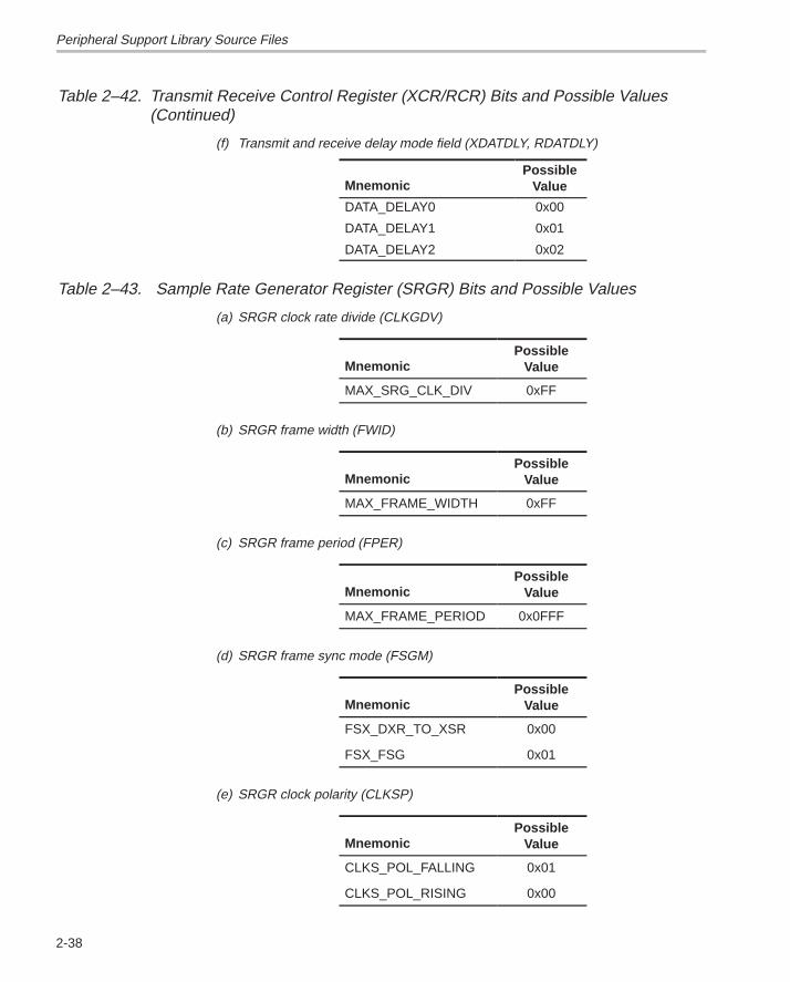
Table 2–42. Transmit Receive Control Register (XCR/RCR) Bits and Possible Values(Continued)
(f) Transmit and receive delay mode field (XDATDLY, RDATDLY)
MnemonicPossible
Value
DATA_DELAY0 0x00
DATA_DELAY1 0x01
DATA_DELAY2 0x02
Table 2–43. Sample Rate Generator Register (SRGR) Bits and Possible Values
(a) SRGR clock rate divide (CLKGDV)
MnemonicPossible
Value
MAX_SRG_CLK_DIV 0xFF
(b) SRGR frame width (FWID)
MnemonicPossible
Value
MAX_FRAME_WIDTH 0xFF
(c) SRGR frame period (FPER)
MnemonicPossible
Value
MAX_FRAME_PERIOD 0x0FFF
(d) SRGR frame sync mode (FSGM)
MnemonicPossible
Value
FSX_DXR_TO_XSR 0x00
FSX_FSG 0x01
(e) SRGR clock polarity (CLKSP)
MnemonicPossible
Value
CLKS_POL_FALLING 0x01
CLKS_POL_RISING 0x00
Peripheral Support Library Source Files
2-39 Source Files Description
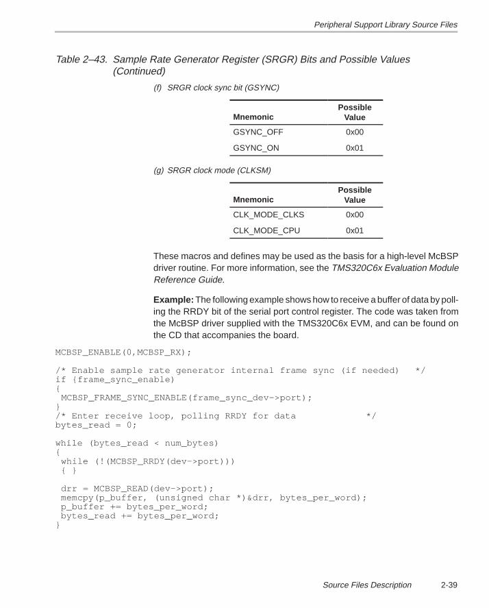
Table 2–43. Sample Rate Generator Register (SRGR) Bits and Possible Values(Continued)
(f) SRGR clock sync bit (GSYNC)
MnemonicPossible
Value
GSYNC_OFF 0x00
GSYNC_ON 0x01
(g) SRGR clock mode (CLKSM)
MnemonicPossible
Value
CLK_MODE_CLKS 0x00
CLK_MODE_CPU 0x01
These macros and defines may be used as the basis for a high-level McBSPdriver routine. For more information, see the TMS320C6x Evaluation ModuleReference Guide.
Example: The following example shows how to receive a buffer of data by poll-ing the RRDY bit of the serial port control register. The code was taken fromthe McBSP driver supplied with the TMS320C6x EVM, and can be found onthe CD that accompanies the board.
MCBSP_ENABLE(0,MCBSP_RX);
/* Enable sample rate generator internal frame sync (if needed) */if {frame_sync_enable){ MCBSP_FRAME_SYNC_ENABLE(frame_sync_dev–>port);}/* Enter receive loop, polling RRDY for data */bytes_read = 0;
while (bytes_read < num_bytes){ while (!(MCBSP_RRDY(dev–>port))) { }
drr = MCBSP_READ(dev–>port); memcpy(p_buffer, (unsigned char *)&drr, bytes_per_word); p_buffer += bytes_per_word; bytes_read += bytes_per_word;}
Peripheral Support Library Source Files
2-40
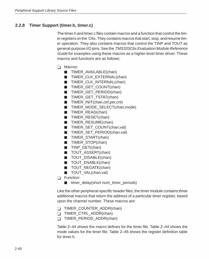
2.2.8 Timer Support (timer.h, timer.c)
The timer.h and timer.c files contain macros and a function that control the tim-er registers on the ‘C6x. They contains macros that start, stop, and resume tim-er operation. They also contains macros that control the TINP and TOUT asgeneral-purpose I/O pins. See the TMS320C6x Evaluation Module ReferenceGuide for examples using these macros as a higher-level timer driver. Thesemacros and functions are as follows:
� Macros:� TIMER_AVAILABLE(chan)� TIMER_CLK_EXTERNAL(chan)� TIMER_CLK_INTERNAL(chan)� TIMER_GET_COUNT(chan)� TIMER_GET_PERIOD(chan)� TIMER_GET_TSTAT(chan)� TIMER_INIT(chan,ctrl,per,cnt)� TIMER_MODE_SELECT(chan,mode)� TIMER_READ(chan)� TIMER_RESET(chan)� TIMER_RESUME(chan)� TIMER_SET_COUNT(chan,val)� TIMER_SET_PERIOD(chan,val)� TIMER_START(chan)� TIMER_STOP(chan)� TINP_GET(chan)� TOUT_ASSERT(chan)� TOUT_DISABLE(chan)� TOUT_ENABLE(chan)� TOUT_NEGATE(chan)� TOUT_VAL(chan,val)
� Function:� timer_delay(short num_timer_periods)
Like the other peripheral-specific header files, the timer module contains threeadditional macros that return the address of a particular timer register, basedupon the channel number. These macros are:
� TIMER_COUNTER_ADDR(chan)� TIMER_CTRL_ADDR(chan)� TIMER_PERIOD_ADDR(chan)
Table 2–44 shows the macro defines for the timer file. Table 2–44 shows themode values for the timer file. Table 2–45 shows the register definition tablefor timer.h.
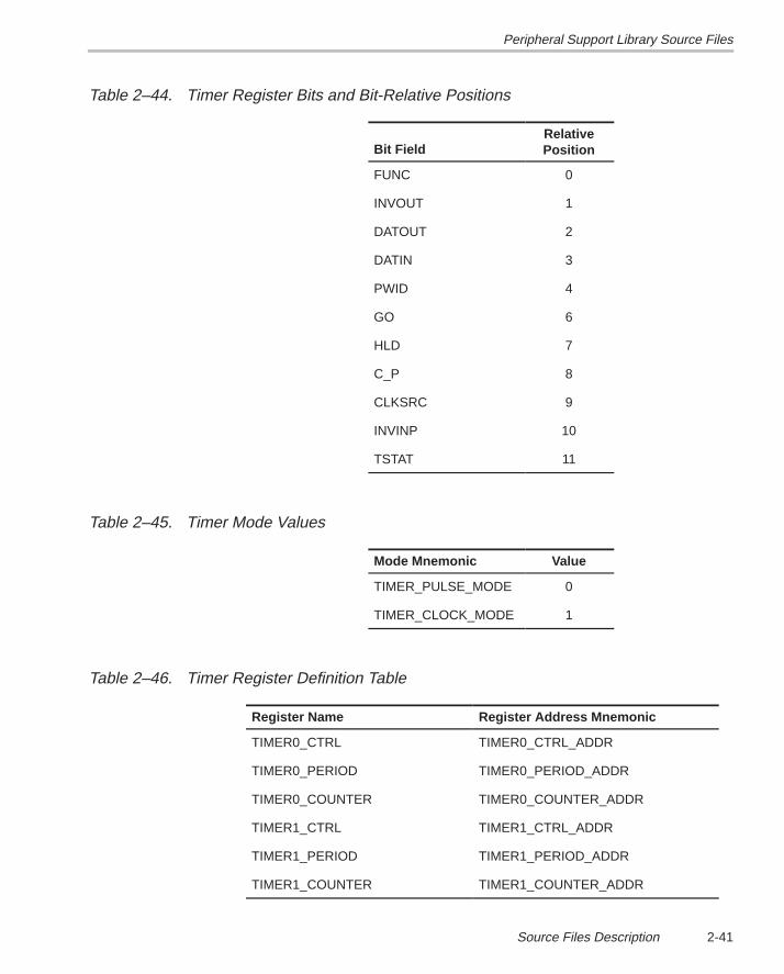
Peripheral Support Library Source Files
2-41 Source Files Description
Table 2–44. Timer Register Bits and Bit-Relative Positions
Bit FieldRelativePosition
FUNC 0
INVOUT 1
DATOUT 2
DATIN 3
PWID 4
GO 6
HLD 7
C_P 8
CLKSRC 9
INVINP 10
TSTAT 11
Table 2–45. Timer Mode Values
Mode Mnemonic Value
TIMER_PULSE_MODE 0
TIMER_CLOCK_MODE 1
Table 2–46. Timer Register Definition Table
Register Name Register Address Mnemonic
TIMER0_CTRL TIMER0_CTRL_ADDR
TIMER0_PERIOD TIMER0_PERIOD_ADDR
TIMER0_COUNTER TIMER0_COUNTER_ADDR
TIMER1_CTRL TIMER1_CTRL_ADDR
TIMER1_PERIOD TIMER1_PERIOD_ADDR
TIMER1_COUNTER TIMER1_COUNTER_ADDR
Peripheral Support Library Source Files
2-42
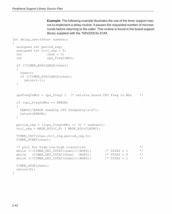
Example: The following example illustrates the use of the timer support mac-ros to implement a delay routine. It pauses the requested number of microse-conds before returning to the caller. This routine is found in the board supportlibrary supplied with the TMS320C6x EVM.
int delay_usec(short numUsec){
unsigned int period_reg;unsigned int ctrl_reg = 0;int chan = 0;int cpu_freqInMhz;
if (!TIMER_AVAILABLE(chan)){
chan++;if (!TIMER_AVAILABLE(chan))
return(–1);}
cpuFreqInMhz = cpu_freq( ) /* returns board CPU freq in Mhz */
if (cpu_freqInMhz == ERROR){
DEBUG(”ERROR reading CPU frequency\n\n”);return(ERROR);
}
period_reg = ((cpu_freqInMhz >> 3) * numUsec);ctrl_reg = MASK_BIG(C_P) � MASK_BIG(CLKSRC);
TIMER_INIT(chan,ctrl_reg,period_reg,0);TIMER_START(chan);
/* poll for high–low–high transition */while (!(TIMER_GET_TSTAT(chan))){NOPS;} /* TSTAT = 1 */while (TIMER_GET_TSTAT(chan) {NOPS;} /* TSTAT = 0 */while (!(TIMER_GET_TSTAT(chan))){NOPS;} /* TSTAT = 1 */
TIMER_STOP(chan);return(0);
}
3-1
Macros and Functions Summary
This chapter consists of tables that list all macros and functions found in the’C6x peripheral support library, listed by the source file in which each appears.The tables provide a concise description of each macro and function and givea page reference to the location in Chapter 4 where each is defined in moredetail.
Chapter 3
3-2
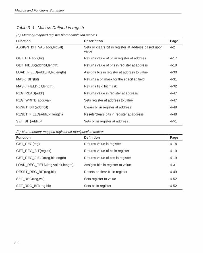
Table 3–1. Macros Defined in regs.h
(a) Memory-mapped register bit-manipulation macros
Function Description Page
ASSIGN_BIT_VAL(addr,bit,val) Sets or clears bit in register at address based uponvalue
4-2
GET_BIT(addr,bit) Returns value of bit in register at address 4-17
GET_FIELD(addr,bit,length) Returns value of bits in register at address 4-18
LOAD_FIELD(addr,val,bit,length) Assigns bits in register at address to value 4-30
MASK_BIT(bit) Returns a bit mask for the specified field 4-31
MASK_FIELD(bit,length) Returns field bit mask 4-32
REG_READ(addr) Returns value in register at address 4-47
REG_WRITE(addr,val) Sets register at address to value 4-47
RESET_BIT(addr,bit) Clears bit in register at address 4-48
RESET_FIELD(addr,bit,length) Resets/clears bits in register at address 4-48
SET_BIT(addr,bit) Sets bit in register at address 4-51
(b) Non-memory-mapped register bit-manipulation macros
Function Definition Page
GET_REG(reg) Returns value in register 4-18
GET_REG_BIT(reg,bit) Returns value of bit in register 4-19
GET_REG_FIELD(reg,bit,length) Returns value of bits in register 4-19
LOAD_REG_FIELD(reg,val,bit,length) Assigns bits in register to value 4-31
RESET_REG_BIT(reg,bit) Resets or clear bit in register 4-49
SET_REG(reg,val) Sets register to value 4-52
SET_REG_BIT(reg,bit) Sets bit in register 4-52
Macros and Functions Summary
3-3Macros and Functions Summary
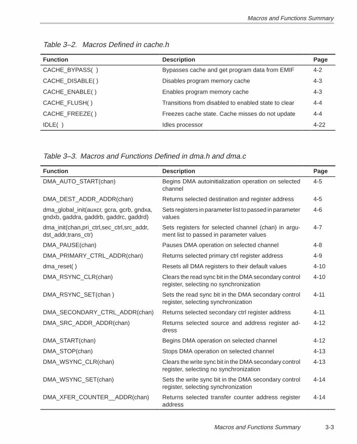
Table 3–2. Macros Defined in cache.h
Function Description Page
CACHE_BYPASS( ) Bypasses cache and get program data from EMIF 4-2
CACHE_DISABLE( ) Disables program memory cache 4-3
CACHE_ENABLE( ) Enables program memory cache 4-3
CACHE_FLUSH( ) Transitions from disabled to enabled state to clear 4-4
CACHE_FREEZE( ) Freezes cache state. Cache misses do not update 4-4
IDLE( ) Idles processor 4-22
Table 3–3. Macros and Functions Defined in dma.h and dma.c
Function Description Page
DMA_AUTO_START(chan) Begins DMA autoinitialization operation on selectedchannel
4-5
DMA_DEST_ADDR_ADDR(chan) Returns selected destination and register address 4-5
dma_global_init(auxcr, gcra, gcrb, gndxa,gndxb, gaddra, gaddrb, gaddrc, gaddrd)
Sets registers in parameter list to passed in parametervalues
4-6
dma_init(chan,pri_ctrl,sec_ctrl,src_addr,dst_addr,trans_ctr)
Sets registers for selected channel (chan) in argu-ment list to passed in parameter values
4-7
DMA_PAUSE(chan) Pauses DMA operation on selected channel 4-8
DMA_PRIMARY_CTRL_ADDR(chan) Returns selected primary ctrl register address 4-9
dma_reset( ) Resets all DMA registers to their default values 4-10
DMA_RSYNC_CLR(chan) Clears the read sync bit in the DMA secondary controlregister, selecting no synchronization
4-10
DMA_RSYNC_SET(chan ) Sets the read sync bit in the DMA secondary controlregister, selecting synchronization
4-11
DMA_SECONDARY_CTRL_ADDR(chan) Returns selected secondary ctrl register address 4-11
DMA_SRC_ADDR_ADDR(chan) Returns selected source and address register ad-dress
4-12
DMA_START(chan) Begins DMA operation on selected channel 4-12
DMA_STOP(chan) Stops DMA operation on selected channel 4-13
DMA_WSYNC_CLR(chan) Clears the write sync bit in the DMA secondary controlregister, selecting no synchronization
4-13
DMA_WSYNC_SET(chan) Sets the write sync bit in the DMA secondary controlregister, selecting synchronization
4-14
DMA_XFER_COUNTER__ADDR(chan) Returns selected transfer counter address registeraddress
4-14
Macros and Functions SummaryMacros and Functions Summary
3-4
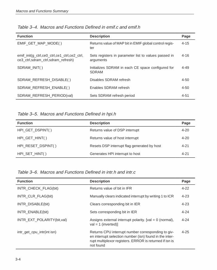
Table 3–4. Macros and Functions Defined in emif.c and emif.h
Function Description Page
EMIF_GET_MAP_MODE( ) Returns value of MAP bit in EMIF global control regis-ter
4-15
emif_init(g_ctrl,ce0_ctrl,ce1_ctrl,ce2_ctrl,ce3_ctrl,sdram_ctrl,sdram_refresh)
Sets registers in parameter list to values passed inarguments
4-16
SDRAM_INIT( ) Initializes SDRAM in each CE space configured forSDRAM
4-49
SDRAM_REFRESH_DISABLE( ) Disables SDRAM refresh 4-50
SDRAM_REFRESH_ENABLE( ) Enables SDRAM refresh 4-50
SDRAM_REFRESH_PERIOD(val) Sets SDRAM refresh period 4-51
Table 3–5. Macros and Functions Defined in hpi.h
Function Description Page
HPI_GET_DSPINT( ) Returns value of DSP interrupt 4-20
HPI_GET_HINT( ) Returns value of host interrupt 4-20
HPI_RESET_DSPINT( ) Resets DSP interrupt flag generated by host 4-21
HPI_SET_HINT( ) Generates HPI interrupt to host 4-21
Table 3–6. Macros and Functions Defined in intr.h and intr.c
Function Description Page
INTR_CHECK_FLAG(bit) Returns value of bit in IFR 4-22
INTR_CLR_FLAG(bit) Manually clears indicated interrupt by writing 1 to ICR 4-23
INTR_DISABLE(bit) Clears corresponding bit in IER 4-23
INTR_ENABLE(bit) Sets corresponding bit in IER 4-24
INTR_EXT_POLARITY(bit,val) Assigns external interrupt polarity. [val = 0 (normal),val = 1 (inverted)]
4-24
intr_get_cpu_intr(int isn) Returns CPU interrupt number corresponding to giv-en interrupt selection number (isn) found in the inter-rupt multiplexor registers. ERROR is returned if isn isnot found
4-25
Macros and Functions Summary
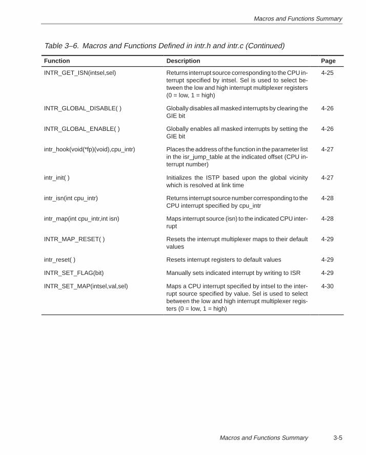
3-5Macros and Functions Summary
Table 3–6. Macros and Functions Defined in intr.h and intr.c (Continued)
Function PageDescription
INTR_GET_ISN(intsel,sel) Returns interrupt source corresponding to the CPU in-terrupt specified by intsel. Sel is used to select be-tween the low and high interrupt multiplexer registers(0 = low, 1 = high)
4-25
INTR_GLOBAL_DISABLE( ) Globally disables all masked interrupts by clearing theGIE bit
4-26
INTR_GLOBAL_ENABLE( ) Globally enables all masked interrupts by setting theGIE bit
4-26
intr_hook(void(*fp)(void),cpu_intr) Places the address of the function in the parameter listin the isr_jump_table at the indicated offset (CPU in-terrupt number)
4-27
intr_init( ) Initializes the ISTP based upon the global vicinitywhich is resolved at link time
4-27
intr_isn(int cpu_intr) Returns interrupt source number corresponding to theCPU interrupt specified by cpu_intr
4-28
intr_map(int cpu_intr,int isn) Maps interrupt source (isn) to the indicated CPU inter-rupt
4-28
INTR_MAP_RESET( ) Resets the interrupt multiplexer maps to their defaultvalues
4-29
intr_reset( ) Resets interrupt registers to default values 4-29
INTR_SET_FLAG(bit) Manually sets indicated interrupt by writing to ISR 4-29
INTR_SET_MAP(intsel,val,sel) Maps a CPU interrupt specified by intsel to the inter-rupt source specified by value. Sel is used to selectbetween the low and high interrupt multiplexer regis-ters (0 = low, 1 = high)
4-30
Macros and Functions Summary
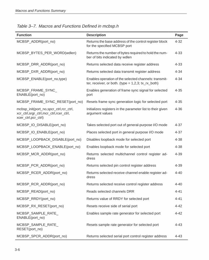
3-6
Table 3–7. Macros and Functions Defined in mcbsp.h
Function Description Page
MCBSP_ADDR(port_no) Returns the base address of the control register blockfor the specified MCBSP port
4-32
MCBSP_BYTES_PER_WORD(wdlen) Returns the number of bytes required to hold the num-ber of bits indicated by wdlen
4-33
MCBSP_DRR_ADDR(port_no) Returns selected data receive register address 4-33
MCBSP_DXR_ADDR(port_no) Returns selected data transmit register address 4-34
MCBSP_ENABLE(port_no,type) Enables operation of the selected channels: transmit-ter, receiver, or both. (type = 1,2,3; tx_rx_both)
4-34
MCBSP_FRAME_SYNC_ENABLE(port_no)
Enables generation of frame sync signal for selectedport
4-35
MCBSP_FRAME_SYNC_RESET(port_no) Resets frame sync generation logic for selected port 4-35
mcbsp_init(port_no,spcr_ctrl,rcr_ctrl,xcr_ctrl,srgr_ctrl,mcr_ctrl,rcer_ctrl,xcer_ctrl,pcr_ctrl)
Initializes registers in the parameter list to their givenargument values
4-36
MCBSP_IO_DISABLE(port_no) Takes selected port out of general-purpose I/O mode 4-37
MCBSP_IO_ENABLE(port_no) Places selected port in general purpose I/O mode 4-37
MCBSP_LOOPBACK_DISABLE(port_no) Disables loopback mode for selected port 4-38
MCBSP_LOOPBACK_ENABLE(port_no) Enables loopback mode for selected port 4-38
MCBSP_MCR_ADDR(port_no) Returns selected multichannel control register ad-dress
4-39
MCBSP_PCR_ADDR(port_no) Returns selected pin control register address 4-39
MCBSP_RCER_ADDR(port_no) Returns selected receive channel enable register ad-dress
4-40
MCBSP_RCR_ADDR(port_no) Returns selected receive control register address 4-40
MCBSP_READ(port_no) Reads selected channels DRR 4-41
MCBSP_RRDY(port_no) Returns value of RRDY for selected port 4-41
MCBSP_RX_RESET(port_no) Resets receive side of serial port 4-42
MCBSP_SAMPLE_RATE_ENABLE(port_no)
Enables sample rate generator for selected port 4-42
MCBSP_SAMPLE_RATE_RESET(port_no)
Resets sample rate generator for selected port 4-43
MCBSP_SPCR_ADDR(port_no) Returns selected serial port control register address 4-43
Macros and Functions SummaryMacros and Functions Summary
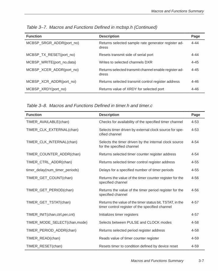
3-7Macros and Functions Summary
Table 3–7. Macros and Functions Defined in mcbsp.h (Continued)
Function PageDescription
MCBSP_SRGR_ADDR(port_no) Returns selected sample rate generator register ad-dress
4-44
MCBSP_TX_RESET(port_no) Resets transmit side of serial port 4-44
MCBSP_WRITE(port_no,data) Writes to selected channels DXR 4-45
MCBSP_XCER_ADDR(port_no) Returns selected transmit channel enable register ad-dress
4-45
MCBSP_XCR_ADDR(port_no) Returns selected transmit control register address 4-46
MCBSP_XRDY(port_no) Returns value of XRDY for selected port 4-46
Table 3–8. Macros and Functions Defined in timer.h and timer.c
Function Description Page
TIMER_AVAILABLE(chan) Checks for availability of the specified timer channel 4-53
TIMER_CLK_EXTERNAL(chan) Selects timer driven by external clock source for spe-cified channel
4-53
TIMER_CLK_INTERNAL(chan) Selects the timer driven by the internal clock sourcefor the specified channel
4-54
TIMER_COUNTER_ADDR(chan) Returns selected timer counter register address 4-54
TIMER_CTRL_ADDR(chan) Returns selected timer control register address 4-55
timer_delay(num_timer_periods) Delays for a specified number of timer periods 4-55
TIMER_GET_COUNT(chan) Returns the value of the timer counter register for thespecified channel
4-56
TIMER_GET_PERIOD(chan) Returns the value of the timer period register for thespecified channel
4-56
TIMER_GET_TSTAT(chan) Returns the value of the timer status bit, TSTAT, in thetimer control register of the specified channel
4-57
TIMER_INIT(chan,ctrl,per,cnt) Initializes timer registers 4-57
TIMER_MODE_SELECT(chan,mode) Selects between PULSE and CLOCK modes 4-58
TIMER_PERIOD_ADDR(chan) Returns selected period register address 4-58
TIMER_READ(chan) Reads value of timer counter register 4-59
TIMER_RESET(chan) Resets timer to condition defined by device reset 4-59
Macros and Functions Summary
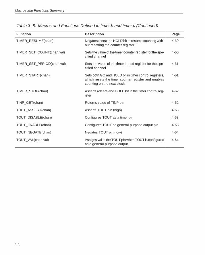
3-8
Table 3–8. Macros and Functions Defined in timer.h and timer.c (Continued)
Function PageDescription
TIMER_RESUME(chan) Negates (sets) the HOLD bit to resume counting with-out resetting the counter register
4-60
TIMER_SET_COUNT(chan,val) Sets the value of the timer counter register for the spe-cified channel
4-60
TIMER_SET_PERIOD(chan,val) Sets the value of the timer period register for the spe-cified channel
4-61
TIMER_START(chan) Sets both GO and HOLD bit in timer control registers,which resets the timer counter register and enablescounting on the next clock
4-61
TIMER_STOP(chan) Asserts (clears) the HOLD bit in the timer control reg-ister
4-62
TINP_GET(chan) Returns value of TINP pin 4-62
TOUT_ASSERT(chan) Asserts TOUT pin (high) 4-63
TOUT_DISABLE(chan) Configures TOUT as a timer pin 4-63
TOUT_ENABLE(chan) Configures TOUT as general-purpose output pin 4-63
TOUT_NEGATE(chan) Negates TOUT pin (low) 4-64
TOUT_VAL(chan,val) Assigns val to the TOUT pin when TOUT is configuredas a general-purpose output
4-64
Macros and Functions Summary
4-1 Macros and Functions Description
Macros and FunctionsDescription
This chapter provides an alphabetical list of all functions and macros providedin the ’C6x peripheral support library. Each entry gives the complete syntaxand description information for the named function or macro, shows where itis defined, and provides a code example. Macros are denoted by uppercasetext and functions are denoted by lowercase.
Chapter 4
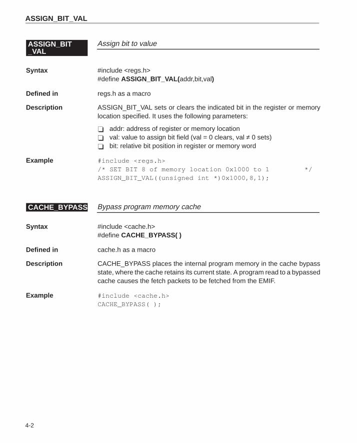
ASSIGN_BIT_VAL
4-2
Assign bit to valueASSIGN_BIT_VAL
Syntax #include <regs.h>#define ASSIGN_BIT_VAL( addr,bit,val)
Defined in regs.h as a macro
Description ASSIGN_BIT_VAL sets or clears the indicated bit in the register or memorylocation specified. It uses the following parameters:
� addr: address of register or memory location� val: value to assign bit field (val = 0 clears, val ≠ 0 sets)� bit: relative bit position in register or memory word
Example #include <regs.h>/* SET BIT 8 of memory location 0x1000 to 1 */ASSIGN_BIT_VAL((unsigned int *)0x1000,8,1);
Bypass program memory cacheCACHE_BYPASS
Syntax #include <cache.h>#define CACHE_BYPASS( )
Defined in cache.h as a macro
Description CACHE_BYPASS places the internal program memory in the cache bypassstate, where the cache retains its current state. A program read to a bypassedcache causes the fetch packets to be fetched from the EMIF.
Example #include <cache.h>CACHE_BYPASS( );
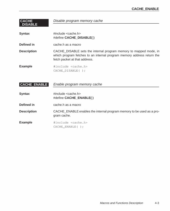
CACHE_ENABLE
4-3 Macros and Functions Description
Disable program memory cacheCACHE_DISABLE
Syntax #include <cache.h>#define CACHE_DISABLE( )
Defined in cache.h as a macro
Description CACHE_DISABLE sets the internal program memory to mapped mode, inwhich program fetches to an internal program memory address return thefetch packet at that address.
Example #include <cache.h>CACHE_DISABLE( );
Enable program memory cacheCACHE_ENABLE
Syntax #include <cache.h>#define CACHE_ENABLE( )
Defined in cache.h as a macro
Description CACHE_ENABLE enables the internal program memory to be used as a pro-gram cache.
Example #include <cache.h>CACHE_ENABLE( );
CACHE_FLUSH
4-4
Flush program memory cacheCACHE_FLUSH
Syntax #include <cache.h>#define CACHE_FLUSH( )
Defined in cache.h as a macro
Description CACHE_FLUSH flushes the cache by transitioning internal program memorymodes from mapped to enabled. This mode transition is the only mechanismthat flushes the cache.
Example #include <cache.h>CACHE_FLUSH( );
Freeze program memory cacheCACHE_FREEZE
Syntax #include <cache.h>#define CACHE_FREEZE( )
Defined in cache.h as a macro
Description CACHE_FREEZE places the internal program memory in the cache freezestate, in which the cache retains its current state. A program read to a frozencache is identical to a read from an enabled cache, with the exception that ona cache miss the data read from the EMIF is not stored in the cache.
Example #include <cache.h>CACHE_FREEZE( );

DMA_DEST_ADDR_ADDR
4-5 Macros and Functions Description
DMA start operation for autoinitializationDMA_AUTO_START
Syntax #include <dma.h>#define DMA_AUTO_START( chan)
Defined in dma.h as a macro
Description DMA_AUTO_START starts the DMA operation of the selected channel by set-ting the START field of the selected channel’s primary control register (PCR)to a value of 11b. After completion of a block transfer, the DMA channel is re-started and the selected DMA channel registers are reloaded. It uses the fol-lowing parameter:
� chan: channel selector (0,1)
Example #include <dma.h>/*Start DMA channel 2 operation using autoinitialization*/DMA_AUTO_START(2);
Selects DMA destination address register addressDMA_DEST_ADDR_ADDR
Syntax #include <dma.h>#define DMA_DEST_ADDR_ADDR(chan)
Defined in dma.h as a macro
Description DMA_DEST_ADDR_ADDR returns the address of the DMA destination ad-dress register for the selected channel. It uses the following parameter:
� chan: channel selector (0,1)
Example #include <dma.h>/* *//*Set destination address for DMA channel register 2*//* */* (unsigned int *) DMA_DEST_ADDR_ADDR(2) = (unsignedint *)0X00400000u;
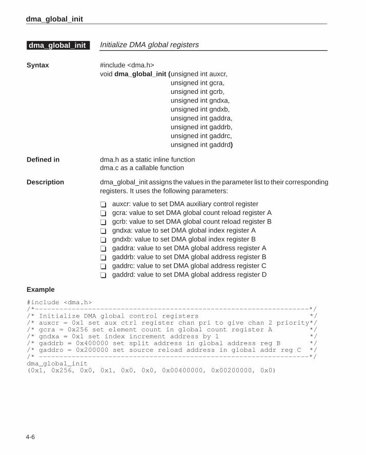
dma_global_init
4-6
Initialize DMA global registersdma_global_init
Syntax #include <dma.h>void dma_global_init (unsigned int auxcr,
unsigned int gcra,unsigned int gcrb,unsigned int gndxa,unsigned int gndxb,unsigned int gaddra,unsigned int gaddrb,unsigned int gaddrc,unsigned int gaddrd)
Defined in dma.h as a static inline functiondma.c as a callable function
Description dma_global_init assigns the values in the parameter list to their correspondingregisters. It uses the following parameters:
� auxcr: value to set DMA auxiliary control register� gcra: value to set DMA global count reload register A� gcrb: value to set DMA global count reload register B� gndxa: value to set DMA global index register A� gndxb: value to set DMA global index register B� gaddra: value to set DMA global address register A� gaddrb: value to set DMA global address register B� gaddrc: value to set DMA global address register C� gaddrd: value to set DMA global address register D
Example
#include <dma.h>/*–––––––––––––––––––––––––––––––––––––––––––––––––––––––––––––––––––*//* Initialize DMA global control registers *//* auxcr = 0x1 set aux ctrl register chan pri to give chan 2 priority*//* gcra = 0x256 set element count in global count register A *//* gndxa = 0x1 set index increment address by 1 *//* gaddrb = 0x400000 set split address in global address reg B *//* gaddro = 0x200000 set source reload address in global addr reg C *//* ––––––––––––––––––––––––––––––––––––––––––––––––––––––––––––––––––*/dma_global_init(0x1, 0x256, 0x0, 0x1, 0x0, 0x0, 0x00400000, 0x00200000, 0x0)
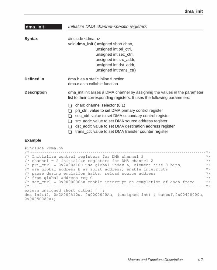
dma_init
4-7 Macros and Functions Description
Initialize DMA channel-specific registersdma_init
Syntax #include <dma.h>void dma_init (unsigned short chan,
unsigned int pri_ctrl,unsigned int sec_ctrl,unsigned int src_addr,unsigned int dst_addr,unsigned int trans_ctr)
Defined in dma.h as a static inline functiondma.c as a callable function
Description dma_init initializes a DMA channel by assigning the values in the parameterlist to their corresponding registers. It uses the following parameters:
� chan: channel selector (0,1)� pri_ctrl: value to set DMA primary control register� sec_ctrl: value to set DMA secondary control register� src_addr: value to set DMA source address register� dst_addr: value to set DMA destination address register� trans_ctr: value to set DMA transfer counter register
Example
#include <dma.h> /* *//* Initialize control registers for DMA channel 2 *//* channel = 2 initialize registers for DMA channel 2 *//* pri_ctrl = 0x2A00A10U use global index A, element size 8 bits, *//* use global address B as split address, enable interrupts *//* pause during emulation halts, reload source address *//* from global address reg C *//* sec_ctrl = 0x0000000Au enable interrupt on completion of each frame *//* */extern unsigned short outbuf [ ];dma_init(2, 0x2A000A10u, 0x0000000Au, (unsigned int) & outbuf,0x00400000u,0x00050080u);
DMA_PAUSE
4-8
DMA pause transferDMA_PAUSE
Syntax #include <dma.h>#define DMA_PAUSE(chan)
Defined in dma.h as a macro
Description DMA_PAUSE pauses the DMA transfer for the indicated channel. Any writetransfers whose read transfer requests are complete is also completed. If theDMA channel has all of the necessary read synchronizations for the next ele-ment, one more element transfer is allowed to complete. DMA_PAUSE usesthe following parameter:
� chan: channel selector (0–3)
Example #include <dma>h>/* *//* Suspend DMA channel 2 operation *//* */DMA_PAUSE (2);
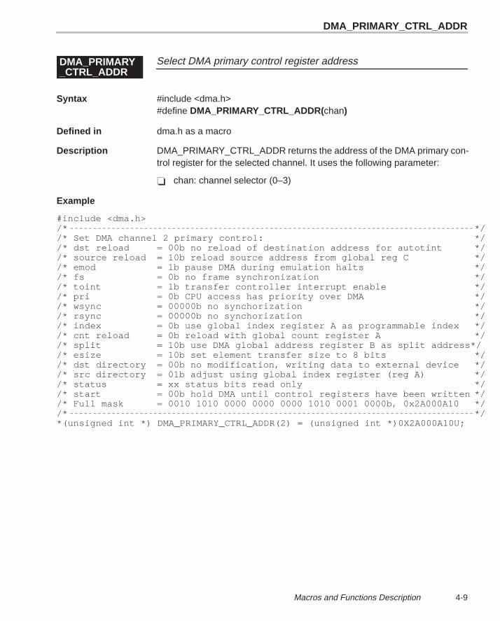
DMA_PRIMARY_CTRL_ADDR
4-9 Macros and Functions Description
Select DMA primary control register addressDMA_PRIMARY_CTRL_ADDR
Syntax #include <dma.h>#define DMA_PRIMARY_CTRL_ADDR( chan)
Defined in dma.h as a macro
Description DMA_PRIMARY_CTRL_ADDR returns the address of the DMA primary con-trol register for the selected channel. It uses the following parameter:
� chan: channel selector (0–3)
Example
#include <dma.h>/* *//* Set DMA channel 2 primary control: *//* dst reload = 00b no reload of destination address for autotint *//* source reload = 10b reload source address from global reg C *//* emod = 1b pause DMA during emulation halts *//* fs = 0b no frame synchronization *//* toint = 1b transfer controller interrupt enable *//* pri = 0b CPU access has priority over DMA *//* wsync = 00000b no synchorization *//* rsync = 00000b no synchorization *//* index = 0b use global index register A as programmable index *//* cnt reload = 0b reload with global count register A *//* split = 10b use DMA global address register B as split address*//* esize = 10b set element transfer size to 8 bits *//* dst directory = 00b no modification, writing data to external device *//* src directory = 01b adjust using global index register (reg A) *//* status = xx status bits read only *//* start = 00b hold DMA until control registers have been written *//* Full mask = 0010 1010 0000 0000 0000 1010 0001 0000b, 0x2A000A10 *//* */*(unsigned int *) DMA_PRIMARY_CTRL_ADDR(2) = (unsigned int *)0X2A000A10U;
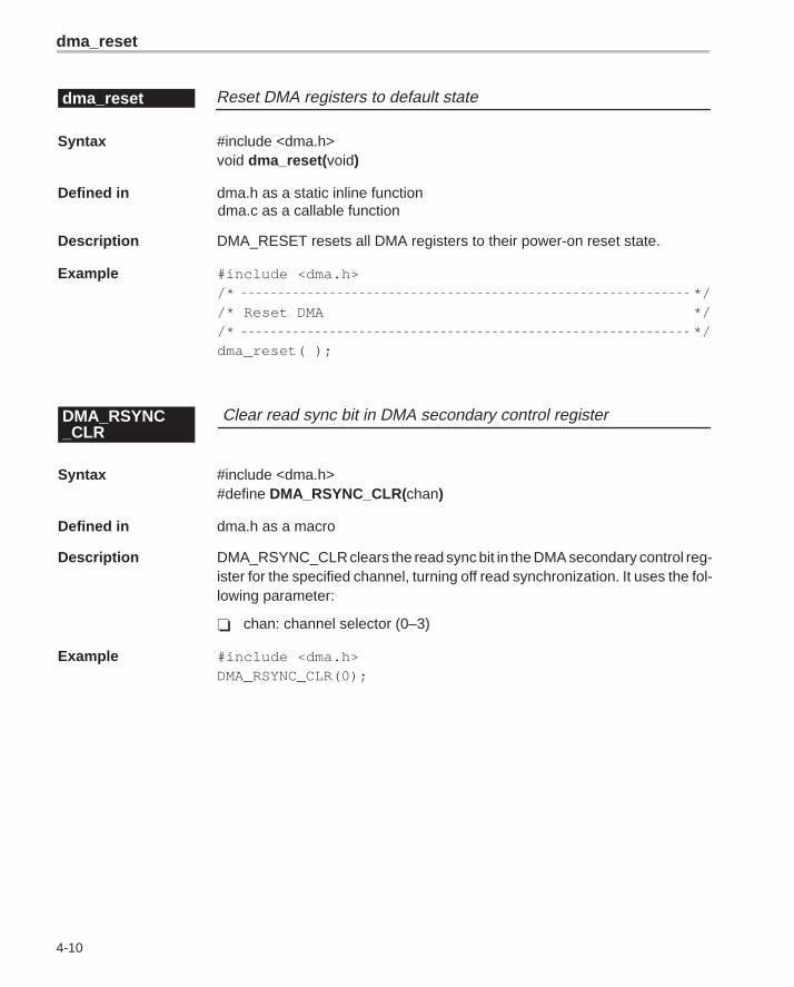
dma_reset
4-10
Reset DMA registers to default statedma_reset
Syntax #include <dma.h>void dma_reset( void)
Defined in dma.h as a static inline functiondma.c as a callable function
Description DMA_RESET resets all DMA registers to their power-on reset state.
Example #include <dma.h>/* *//* Reset DMA *//* */dma_reset( );
Clear read sync bit in DMA secondary control registerDMA_RSYNC_CLR
Syntax #include <dma.h>#define DMA_RSYNC_CLR(chan)
Defined in dma.h as a macro
Description DMA_RSYNC_CLR clears the read sync bit in the DMA secondary control reg-ister for the specified channel, turning off read synchronization. It uses the fol-lowing parameter:
� chan: channel selector (0–3)
Example #include <dma.h>DMA_RSYNC_CLR(0);
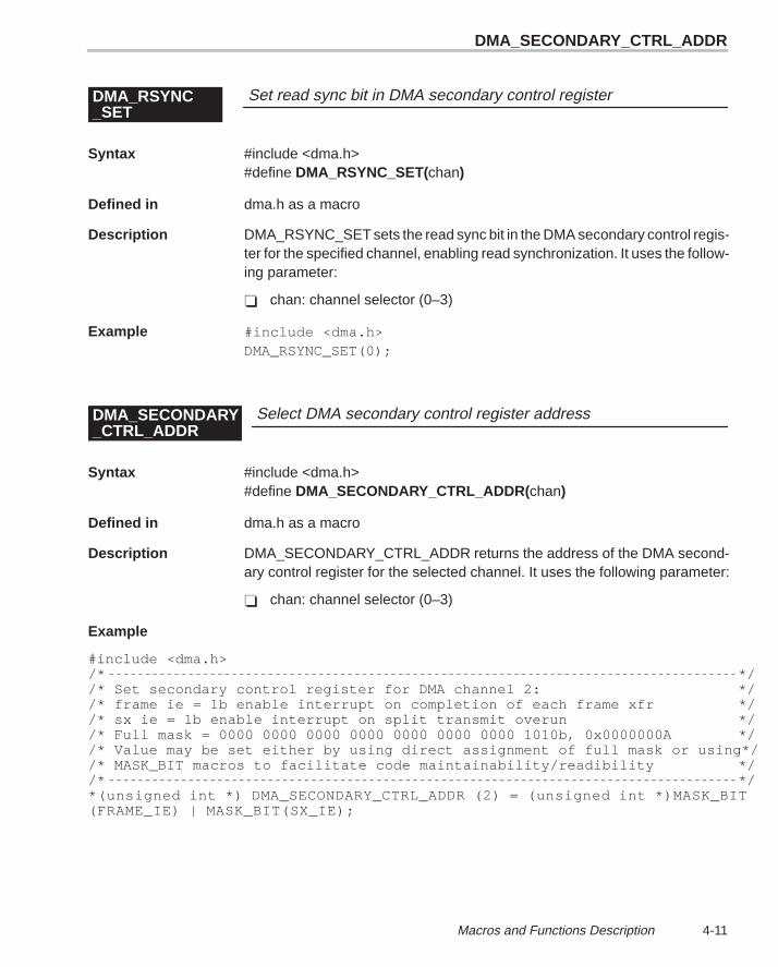
DMA_SECONDARY_CTRL_ADDR
4-11 Macros and Functions Description
Set read sync bit in DMA secondary control registerDMA_RSYNC_SET
Syntax #include <dma.h>#define DMA_RSYNC_SET(chan)
Defined in dma.h as a macro
Description DMA_RSYNC_SET sets the read sync bit in the DMA secondary control regis-ter for the specified channel, enabling read synchronization. It uses the follow-ing parameter:
� chan: channel selector (0–3)
Example #include <dma.h>DMA_RSYNC_SET(0);
Select DMA secondary control register addressDMA_SECONDARY_CTRL_ADDR
Syntax #include <dma.h>#define DMA_SECONDARY_CTRL_ADDR( chan)
Defined in dma.h as a macro
Description DMA_SECONDARY_CTRL_ADDR returns the address of the DMA second-ary control register for the selected channel. It uses the following parameter:
� chan: channel selector (0–3)
Example
#include <dma.h>/* *//* Set secondary control register for DMA channel 2: *//* frame ie = 1b enable interrupt on completion of each frame xfr *//* sx ie = 1b enable interrupt on split transmit overun *//* Full mask = 0000 0000 0000 0000 0000 0000 0000 1010b, 0x0000000A *//* Value may be set either by using direct assignment of full mask or using*//* MASK_BIT macros to facilitate code maintainability/readibility *//* */*(unsigned int *) DMA_SECONDARY_CTRL_ADDR (2) = (unsigned int *)MASK_BIT(FRAME_IE) | MASK_BIT(SX_IE);
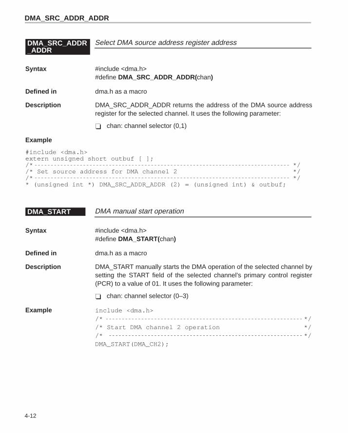
DMA_SRC_ADDR_ADDR
4-12
Select DMA source address register addressDMA_SRC_ADDR_ADDR
Syntax #include <dma.h>#define DMA_SRC_ADDR_ADDR(chan)
Defined in dma.h as a macro
Description DMA_SRC_ADDR_ADDR returns the address of the DMA source addressregister for the selected channel. It uses the following parameter:
� chan: channel selector (0,1)
Example
#include <dma.h>extern unsigned short outbuf [ ];/* *//* Set source address for DMA channel 2 *//* */* (unsigned int *) DMA_SRC_ADDR_ADDR (2) = (unsigned int) & outbuf;
DMA manual start operationDMA_START
Syntax #include <dma.h>#define DMA_START(chan)
Defined in dma.h as a macro
Description DMA_START manually starts the DMA operation of the selected channel bysetting the START field of the selected channel’s primary control register(PCR) to a value of 01. It uses the following parameter:
� chan: channel selector (0–3)
Example include <dma.h>/* *//* Start DMA channel 2 operation *//* */DMA_START(DMA_CH2);
DMA_WSYNC_CLR
4-13 Macros and Functions Description
DMA stop transferDMA_STOP
Syntax #include <dma.h>#define DMA_STOP(chan)
Defined in dma.h as a macro
Description DMA_STOP immediately stops the DMA operation on the selected channeland discards any data from completed read transfers that is held internally. Ituses the following parameter:
� chan: channel selector (0–3)
Example #include <dma.h>DMA_STOP(DMA_CH2);
Clear write sync bit in DMA secondary control registerDMA_WSYNC_CLR
Syntax #include <dma.h>#define DMA_WSYNC_CLR(chan)
Defined in dma.h as a macro
Description DMA_WSYNC_CLR clears the write sync bit in the DMA secondary controlregister for the specified channel, turning off write synchronization. It uses thefollowing parameter:
� chan: channel selector (0–3)
Example #include <dma.h>DMA_WSYNC_CLR(0);
DMA_WSYNC_SET
4-14
Set write sync bit in DMA secondary control registerDMA_WSYNC_SET
Syntax #include <dma.h>#define DMA_WSYNC_SET(chan)
Defined in dma.h as a macro
Description DMA_WSYNC_SET sets the write sync bit in the DMA secondary control reg-ister for the specified channel, enabling write synchronization. It uses the fol-lowing parameter:
� chan: channel selector (0–3)
Example #include <dma.h>DMA_WSYNC_SET(0);
Select DMA transfer counter register addressDMA_XFER_COUNTER_ADDR
Syntax #include <dma.h>#define DMA_XFER_COUNTER_ADDR(chan)
Defined in dma.h as a macro
Description DMA_XFER_COUNTER_ADDR returns the address of the DMA transfercounter register for the selected channel.
� chan: channel selector (0–3)
Example #include <dma.h> /* Get address of transfer counter for DMA channel 2 */unsigned int *xfer_counter = (unsigned int *)DMA_XFER_COUNTER_ADDR(2);
EMIF_GET_MAP_MODE
4-15 Macros and Functions Description
Return value of MAP bit in EMIF global control registerEMIF_GET_MAP_MODE
Syntax #include <emif.h>#define EMIF_GET_MAP_MODE( )
Defined in emif.h as a macro
Description EMIF_GET_MAP_MODE returns the value of the MAP bit in the EMIF globalcontrol register. The MAP bit determines whether internal or external memoryis mapped at address 0.
Example #include <emif.h> unsigned short map = EMIF_GET_MAP_MODE( );
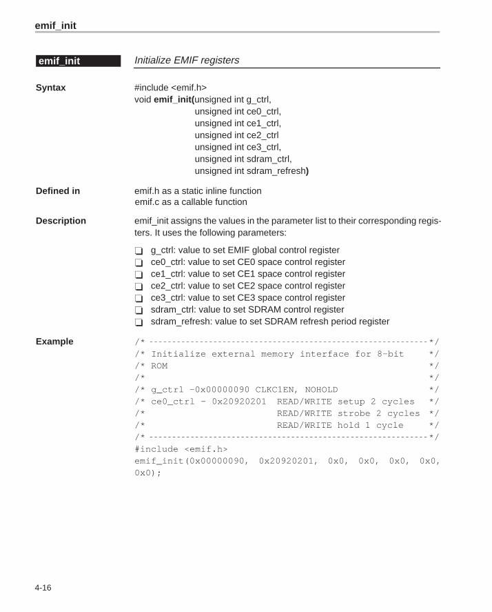
emif_init
4-16
Initialize EMIF registersemif_init
Syntax #include <emif.h>void emif_init( unsigned int g_ctrl,
unsigned int ce0_ctrl,unsigned int ce1_ctrl,unsigned int ce2_ctrlunsigned int ce3_ctrl,unsigned int sdram_ctrl,unsigned int sdram_refresh)
Defined in emif.h as a static inline functionemif.c as a callable function
Description emif_init assigns the values in the parameter list to their corresponding regis-ters. It uses the following parameters:
� g_ctrl: value to set EMIF global control register� ce0_ctrl: value to set CE0 space control register� ce1_ctrl: value to set CE1 space control register� ce2_ctrl: value to set CE2 space control register� ce3_ctrl: value to set CE3 space control register� sdram_ctrl: value to set SDRAM control register� sdram_refresh: value to set SDRAM refresh period register
Example /* *//* Initialize external memory interface for 8-bit *//* ROM *//* *//* g_ctrl –0x00000090 CLKC1EN, NOHOLD *//* ce0_ctrl – 0x20920201 READ/WRITE setup 2 cycles *//* READ/WRITE strobe 2 cycles *//* READ/WRITE hold 1 cycle *//* */#include <emif.h>emif_init(0x00000090, 0x20920201, 0x0, 0x0, 0x0, 0x0,0x0);
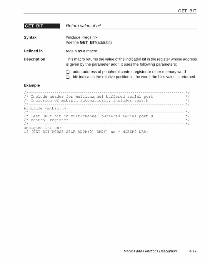
GET_BIT
4-17 Macros and Functions Description
Return value of bitGET_BIT
Syntax #include <regs.h>#define GET_BIT(addr,bit)
Defined in regs.h as a macro
Description This macro returns the value of the indicated bit in the register whose addressis given by the parameter addr. It uses the following parameters:
� addr: address of peripheral control register or other memory word� bit: indicates the relative position in the word, the bit’s value is returned
Example
/* *//* Include header for multichannel buffered serial port *//* Inclusion of mcbsp.h automatically includes regs.h *//* */#include <mcbsp.h>/* *//* Test RRDY bit in multichannel buffered serial port 0 *//* control register *//* */unsigned int xx;if (GET_BIT(MCBSP_SPCR_ADDR(0),RRDY) xx = MCBSP0_DRR;
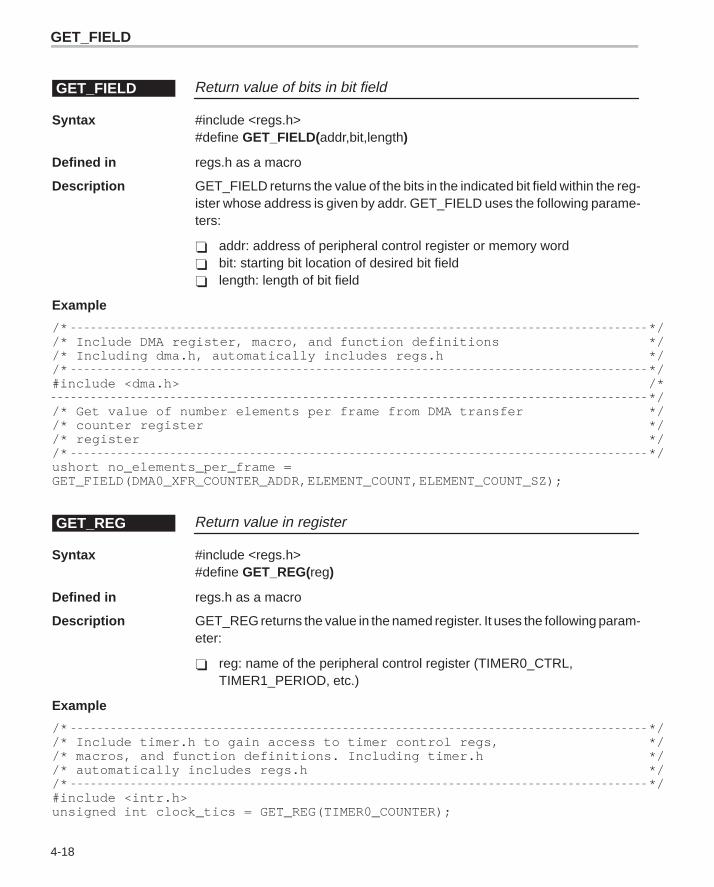
GET_FIELD
4-18
Return value of bits in bit fieldGET_FIELD
Syntax #include <regs.h>#define GET_FIELD(addr,bit,length)
Defined in regs.h as a macro
Description GET_FIELD returns the value of the bits in the indicated bit field within the reg-ister whose address is given by addr. GET_FIELD uses the following parame-ters:
� addr: address of peripheral control register or memory word� bit: starting bit location of desired bit field� length: length of bit field
Example
/* *//* Include DMA register, macro, and function definitions *//* Including dma.h, automatically includes regs.h *//* */#include <dma.h> /*
*//* Get value of number elements per frame from DMA transfer *//* counter register *//* register *//* */ushort no_elements_per_frame = GET_FIELD(DMA0_XFR_COUNTER_ADDR,ELEMENT_COUNT,ELEMENT_COUNT_SZ);
Return value in registerGET_REG
Syntax #include <regs.h>#define GET_REG(reg)
Defined in regs.h as a macro
Description GET_REG returns the value in the named register. It uses the following param-eter:
� reg: name of the peripheral control register (TIMER0_CTRL,TIMER1_PERIOD, etc.)
Example
/* *//* Include timer.h to gain access to timer control regs, *//* macros, and function definitions. Including timer.h *//* automatically includes regs.h *//* */#include <intr.h>unsigned int clock_tics = GET_REG(TIMER0_COUNTER);
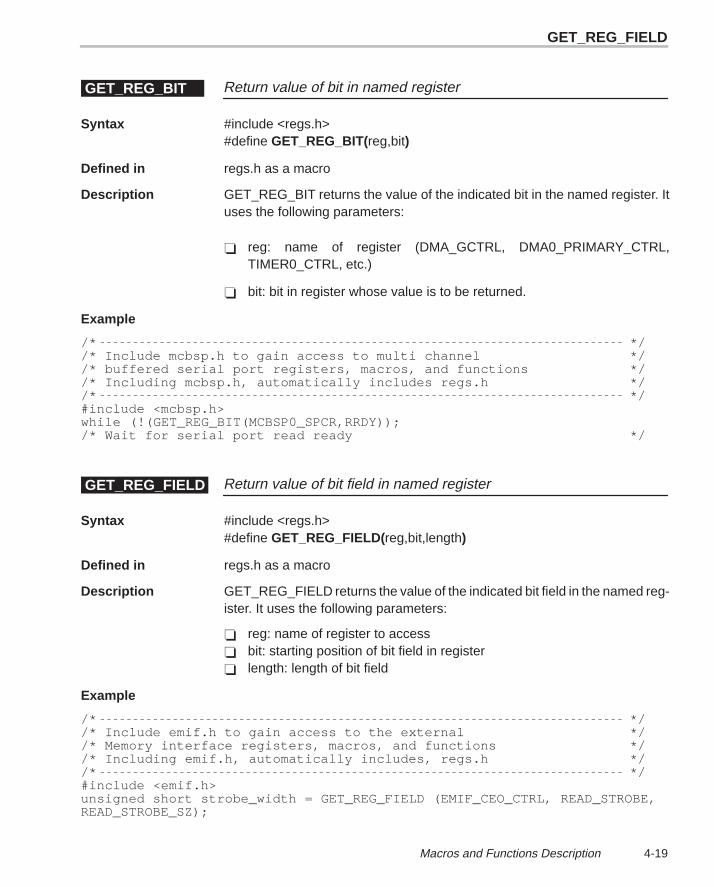
GET_REG_FIELD
4-19 Macros and Functions Description
Return value of bit in named registerGET_REG_BIT
Syntax #include <regs.h>#define GET_REG_BIT(reg,bit)
Defined in regs.h as a macro
Description GET_REG_BIT returns the value of the indicated bit in the named register. Ituses the following parameters:
� reg: name of register (DMA_GCTRL, DMA0_PRIMARY_CTRL,TIMER0_CTRL, etc.)
� bit: bit in register whose value is to be returned.
Example
/* *//* Include mcbsp.h to gain access to multi channel *//* buffered serial port registers, macros, and functions *//* Including mcbsp.h, automatically includes regs.h *//* */#include <mcbsp.h>while (!(GET_REG_BIT(MCBSP0_SPCR,RRDY));/* Wait for serial port read ready */
Return value of bit field in named registerGET_REG_FIELD
Syntax #include <regs.h>#define GET_REG_FIELD(reg,bit,length)
Defined in regs.h as a macro
Description GET_REG_FIELD returns the value of the indicated bit field in the named reg-ister. It uses the following parameters:
� reg: name of register to access� bit: starting position of bit field in register� length: length of bit field
Example
/* *//* Include emif.h to gain access to the external *//* Memory interface registers, macros, and functions *//* Including emif.h, automatically includes, regs.h *//* */#include <emif.h>unsigned short strobe_width = GET_REG_FIELD (EMIF_CEO_CTRL, READ_STROBE,READ_STROBE_SZ);
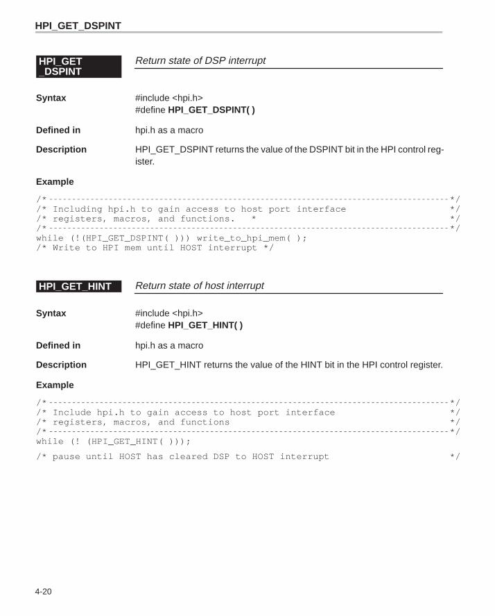
HPI_GET_DSPINT
4-20
Return state of DSP interruptHPI_GET_DSPINT
Syntax #include <hpi.h>#define HPI_GET_DSPINT( )
Defined in hpi.h as a macro
Description HPI_GET_DSPINT returns the value of the DSPINT bit in the HPI control reg-ister.
Example
/* *//* Including hpi.h to gain access to host port interface *//* registers, macros, and functions. * *//* */while (!(HPI_GET_DSPINT( ))) write_to_hpi_mem( );/* Write to HPI mem until HOST interrupt */
Return state of host interruptHPI_GET_HINT
Syntax #include <hpi.h>#define HPI_GET_HINT( )
Defined in hpi.h as a macro
Description HPI_GET_HINT returns the value of the HINT bit in the HPI control register.
Example
/* *//* Include hpi.h to gain access to host port interface *//* registers, macros, and functions *//* */while (! (HPI_GET_HINT( )));
/* pause until HOST has cleared DSP to HOST interrupt */
HPI_SET_HINT
4-21 Macros and Functions Description
Reset/clear DSP interruptHPI_RESET_DSPINT
Syntax #include <hpi.h>#define HPI_RESET_DSPINT( )
Defined in hpi.h as a macro
Description HPI_RESET_DSPINT resets/clears the DSPINT signal by writing a 1 to theDSPINT bit in the HPI control register.
Example
/* *//* Include hpi.h to gain access to host port interface *//* registers, macros, and functions *//* */HPI_RESET_DSPINT( );
Generate host interruptHPI_SET_HINT
Syntax #include <hpi.h>#define HPI_SET_HINT( )
Defined in hpi.h as a macro
Description HPI_SET_HINT sets the HINT bit in the HPI control register that generates ahost interrupt.
Example
/* *//* Include hpi.h to gain access to host port interface *//* registers, macros, and functions. *//* */#include <hpi.h>HPI_SET_HINT( );
/* Send interrupt to host processor */
IDLE
4-22
Idle the processorIDLE
Syntax #include <cache.h>#define IDLE( )
Defined in cache.h as a macro
Description IDLE issues the assembly instruction IDLE, which performs a multicycle NOP.The idle is broken when an interrupt is serviced.
Example /* *//* Idle CPU *//* */#include <cache.h>IDLE( );
Check value of bit in IFRINTR_CHECK_FLAG
Syntax #include <intr.h>#define INTR_CHECK_FLAG( bit)
Defined in intr.h as a macro
Description INTR_CHECK_FLAG returns the value of the indicated bit in the Interrupt flagregister (IFR). It uses the following parameter:
� bit: bit position in interrupt flag register to poll
Example #include <intr.h>while (INTR_CHECK_FLAG (CPU_INT14));
INTR_DISABLE
4-23 Macros and Functions Description
Clear interrupt manuallyINTR_CLR_FLAG
Syntax #include <intr.h>#define INTR_CLR_FLAG( bit)
Defined in intr.h as a macro
Description INTR_CLR_FLAG manually clears the selected interrupt by writing a 1 to thespecified bit in the ICR. Writing a 1 to IC4–IC15 in the ICR causes the corre-sponding bit in the IFR to be cleared. INTR_CLR_FLAG uses the following pa-rameter:
� bit: CPU interrupt (value 0–15) that must be cleared
Example #include <intr.h>INTR_CLR_FLAG (CPU_INT14);
Disable interruptINTR_DISABLE
Syntax #include <intr.h>#define INTR_DISABLE( bit)
Defined in intr.h as a macro
Description intr_disable disables the specified interrupt by clearing the indicated bit in theinterrupt enable register (IER). It uses the following parameter:
� bit: CPU interrupt (value 0–15) that disables the specified interrupt
Example #include <intr.h>INTR_DISABLE (CPU_14);/* Disable CPU 14 interrupt */
INTR_ENABLE
4-24
Enable interruptINTR_ENABLE
Syntax #include <intr.h>#define INTR_ENABLE( bit)
Defined in intr.h as a macro
Description intr_enable (bit) enables the specified interrupt by setting the indicated bit inthe interrupt enable register (IER). It uses the following parameter:
� bit: CPU interrupt (value 0–15) that enables the specified interrupt
Example #include <intr.h>INTR_ENABLE (CPU_INT14);/* Enable CPU 14 interrupt */
Set polarity for external interruptsINTR_EXT_POLARITY
Syntax #include <intr.h>#define INTR_EXT_POLARITY(bit,val)
Defined in intr.h as a macro
Description INTR_EXT_POLARITY sets polarity of the four external interrupts by writingto the external interrupt polarity register. It uses the following parameters:
� bit: bit in external polarity register (0 – affects external interrupt-4 polarity,1 – affects external interrupt-5 polarity, 2 – affects external interrupt-6 po-larity, 3 – affects external interrupt-7 polarity)
� val: 0/1 clears/sets (respectively) the external polarity for the specified ex-ternal interrupt
Example #include <intr.h>INTR_EXT_POLARITY (XIP4; 1);/* Invert external polarity for external interrupt #4*/
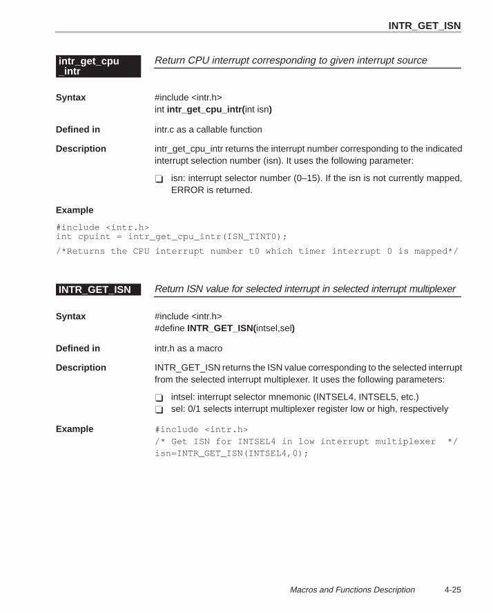
INTR_GET_ISN
4-25 Macros and Functions Description
Return CPU interrupt corresponding to given interrupt sourceintr_get_cpu_intr
Syntax #include <intr.h>int intr_get_cpu_intr( int isn)
Defined in intr.c as a callable function
Description intr_get_cpu_intr returns the interrupt number corresponding to the indicatedinterrupt selection number (isn). It uses the following parameter:
� isn: interrupt selector number (0–15). If the isn is not currently mapped,ERROR is returned.
Example
#include <intr.h> int cpuint = intr_get_cpu_intr(ISN_TINT0);
/*Returns the CPU interrupt number t0 which timer interrupt 0 is mapped*/
Return ISN value for selected interrupt in selected interrupt multiplexerINTR_GET_ISN
Syntax #include <intr.h>#define INTR_GET_ISN(intsel,sel)
Defined in intr.h as a macro
Description INTR_GET_ISN returns the ISN value corresponding to the selected interruptfrom the selected interrupt multiplexer. It uses the following parameters:
� intsel: interrupt selector mnemonic (INTSEL4, INTSEL5, etc.)� sel: 0/1 selects interrupt multiplexer register low or high, respectively
Example #include <intr.h> /* Get ISN for INTSEL4 in low interrupt multiplexer */isn=INTR_GET_ISN(INTSEL4,0);
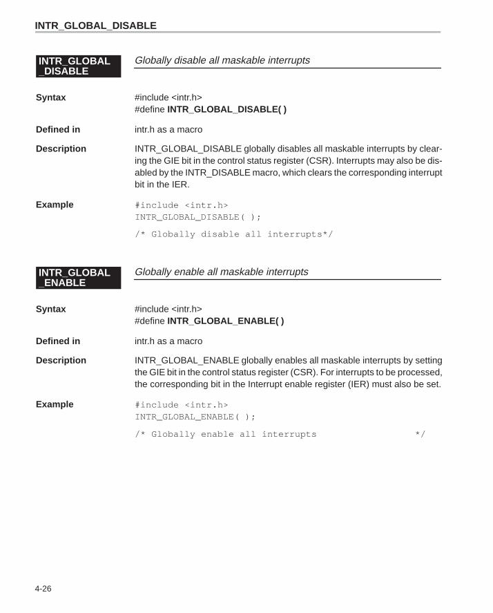
INTR_GLOBAL_DISABLE
4-26
Globally disable all maskable interruptsINTR_GLOBAL_DISABLE
Syntax #include <intr.h>#define INTR_GLOBAL_DISABLE( )
Defined in intr.h as a macro
Description INTR_GLOBAL_DISABLE globally disables all maskable interrupts by clear-ing the GIE bit in the control status register (CSR). Interrupts may also be dis-abled by the INTR_DISABLE macro, which clears the corresponding interruptbit in the IER.
Example #include <intr.h>INTR_GLOBAL_DISABLE( );
/* Globally disable all interrupts*/
Globally enable all maskable interruptsINTR_GLOBAL_ENABLE
Syntax #include <intr.h>#define INTR_GLOBAL_ENABLE( )
Defined in intr.h as a macro
Description INTR_GLOBAL_ENABLE globally enables all maskable interrupts by settingthe GIE bit in the control status register (CSR). For interrupts to be processed,the corresponding bit in the Interrupt enable register (IER) must also be set.
Example #include <intr.h>INTR_GLOBAL_ENABLE( );
/* Globally enable all interrupts */
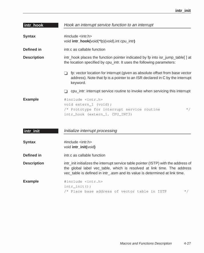
intr_init
4-27 Macros and Functions Description
Hook an interrupt service function to an interruptintr_hook
Syntax #include <intr.h>void intr_hook( void(*fp)(void),int cpu_intr)
Defined in intr.c as callable function
Description intr_hook places the function pointer indicated by fp into isr_jump_table[ ] atthe location specified by cpu_intr. It uses the following parameters:
� fp: vector location for interrupt (given as absolute offset from base vectoraddress). Note that fp is a pointer to an ISR declared in C by the interruptkeyword.
� cpu_intr: interrupt service routine to invoke when servicing this interrupt
Example #include <intr.h>void extern_1 (void);/* Prototype for interrupt service routine */intr_hook (extern_1, CPU_INT3)
Initialize interrupt processingintr_init
Syntax #include <intr.h>void intr_init( void)
Defined in intr.c as callable function
Description intr_init initializes the interrupt service table pointer (ISTP) with the address ofthe global label vec_table, which is resolved at link time. The addressvec_table is defined in intr_.asm and its value is determined at link time.
Example #include <intr.h>intr_init();/* Place base address of vector table in ISTP */
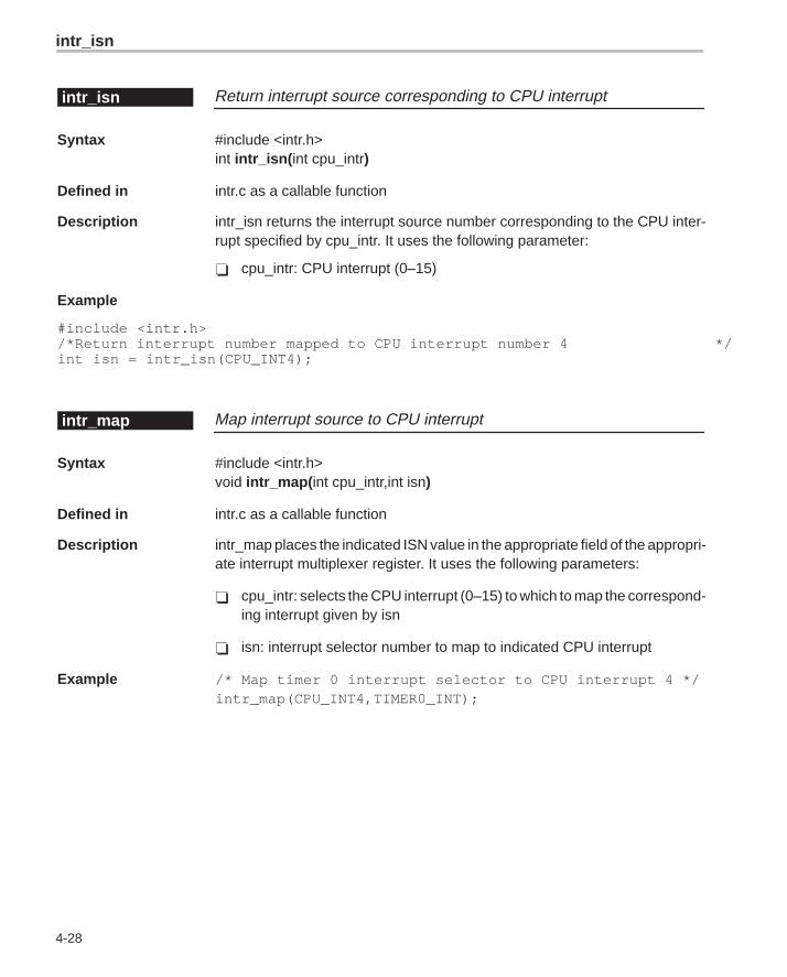
intr_isn
4-28
Return interrupt source corresponding to CPU interruptintr_isn
Syntax #include <intr.h>int intr_isn( int cpu_intr)
Defined in intr.c as a callable function
Description intr_isn returns the interrupt source number corresponding to the CPU inter-rupt specified by cpu_intr. It uses the following parameter:
� cpu_intr: CPU interrupt (0–15)
Example
#include <intr.h>/*Return interrupt number mapped to CPU interrupt number 4 */int isn = intr_isn(CPU_INT4);
Map interrupt source to CPU interruptintr_map
Syntax #include <intr.h>void intr_map( int cpu_intr,int isn)
Defined in intr.c as a callable function
Description intr_map places the indicated ISN value in the appropriate field of the appropri-ate interrupt multiplexer register. It uses the following parameters:
� cpu_intr: selects the CPU interrupt (0–15) to which to map the correspond-ing interrupt given by isn
� isn: interrupt selector number to map to indicated CPU interrupt
Example /* Map timer 0 interrupt selector to CPU interrupt 4 */intr_map(CPU_INT4,TIMER0_INT);
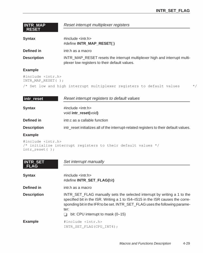
INTR_SET_FLAG
4-29 Macros and Functions Description
Reset interrupt multiplexer registersINTR_MAP_RESET
Syntax #include <intr.h>#define INTR_MAP_RESET( )
Defined in intr.h as a macro
Description INTR_MAP_RESET resets the interrupt multiplexer high and interrupt multi-plexer low registers to their default values.
Example
#include <intr.h>INTR_MAP_RESET( );
/* Set low and high interrupt multiplexer registers to default values */
Reset interrupt registers to default valuesintr_reset
Syntax #include <intr.h>void intr_reset( void)
Defined in intr.c as a callable function
Description intr_reset initializes all of the interrupt-related registers to their default values.
Example
#include <intr.h>/* initialize interrupt registers to their default values */intr_reset( );
Set interrupt manuallyINTR_SET_FLAG
Syntax #include <intr.h>#define INTR_SET_FLAG(bit)
Defined in intr.h as a macro
Description INTR_SET_FLAG manually sets the selected interrupt by writing a 1 to thespecified bit in the ISR. Writing a 1 to IS4–IS15 in the ISR causes the corre-sponding bit in the IFR to be set. INTR_SET_FLAG uses the following parame-ter:� bit: CPU interrupt to mask (0–15)
Example #include <intr.h>INTR_SET_FLAG(CPU_INT4);
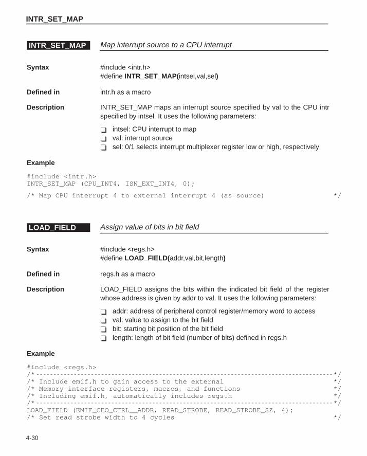
INTR_SET_MAP
4-30
Map interrupt source to a CPU interruptINTR_SET_MAP
Syntax #include <intr.h>#define INTR_SET_MAP(intsel,val,sel)
Defined in intr.h as a macro
Description INTR_SET_MAP maps an interrupt source specified by val to the CPU intrspecified by intsel. It uses the following parameters:
� intsel: CPU interrupt to map� val: interrupt source� sel: 0/1 selects interrupt multiplexer register low or high, respectively
Example
#include <intr.h>INTR_SET_MAP (CPU_INT4, ISN_EXT_INT4, 0);
/* Map CPU interrupt 4 to external interrupt 4 (as source) */
Assign value of bits in bit fieldLOAD_FIELD
Syntax #include <regs.h>#define LOAD_FIELD( addr,val,bit,length)
Defined in regs.h as a macro
Description LOAD_FIELD assigns the bits within the indicated bit field of the registerwhose address is given by addr to val. It uses the following parameters:
� addr: address of peripheral control register/memory word to access� val: value to assign to the bit field� bit: starting bit position of the bit field� length: length of bit field (number of bits) defined in regs.h
Example
#include <regs.h>/* *//* Include emif.h to gain access to the external *//* Memory interface registers, macros, and functions *//* Including emif.h, automatically includes regs.h *//* */LOAD_FIELD (EMIF_CEO_CTRL__ADDR, READ_STROBE, READ_STROBE_SZ, 4); /* Set read strobe width to 4 cycles */
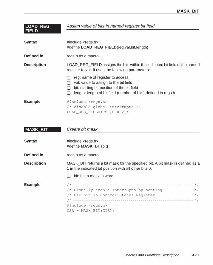
MASK_BIT
4-31 Macros and Functions Description
Assign value of bits in named register bit fieldLOAD_REG_FIELD
Syntax #include <regs.h>#define LOAD_REG_FIELD( reg,val,bit,length)
Defined in regs.h as a macro
Description LOAD_REG_FIELD assigns the bits within the indicated bit field of the namedregister to val. It uses the following parameters:
� reg: name of register to access� val: value to assign to the bit field� bit: starting bit position of the bit field� length: length of bit field (number of bits) defined in regs.h
Example #include <regs.h>/* disable global interrupts */LOAD_REG_FIELD(CSR,0,0,2);
Create bit maskMASK_BIT
Syntax #include <regs.h>#define MASK_BIT( bit)
Defined in regs.h as a macro
Description MASK_BIT returns a bit mask for the specified bit. A bit mask is defined as a1 in the indicated bit position with all other bits 0.
� bit: bit to mask in word
Example /* *//* Globally enable interrupts by setting *//* GIE bit in Control Status Register *//* */#include <regs.h>CSR = MASK_BIT(GIE);
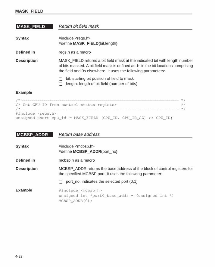
MASK_FIELD
4-32
Return bit field maskMASK_FIELD
Syntax #include <regs.h>#define MASK_FIELD( bit,length)
Defined in regs.h as a macro
Description MASK_FIELD returns a bit field mask at the indicated bit with length numberof bits masked. A bit field mask is defined as 1s in the bit locations comprisingthe field and 0s elsewhere. It uses the following parameters:
� bit: starting bit position of field to mask� length: length of bit field (number of bits)
Example
/* *//* Get CPU ID from control status register *//* */#include <regs.h>unsigned short cpu_id |= MASK_FIELD (CPU_ID, CPU_ID_SZ) >> CPU_ID;
Return base addressMCBSP_ADDR
Syntax #include <mcbsp.h>#define MCBSP_ADDR(port_no)
Defined in mcbsp.h as a macro
Description MCBSP_ADDR returns the base address of the block of control registers forthe specified MCBSP port. It uses the following parameter:
� port_no: indicates the selected port (0,1)
Example #include <mcbsp.h>unsigned int *port0_base_addr = (unsigned int *)MCBSP_ADDR(0);
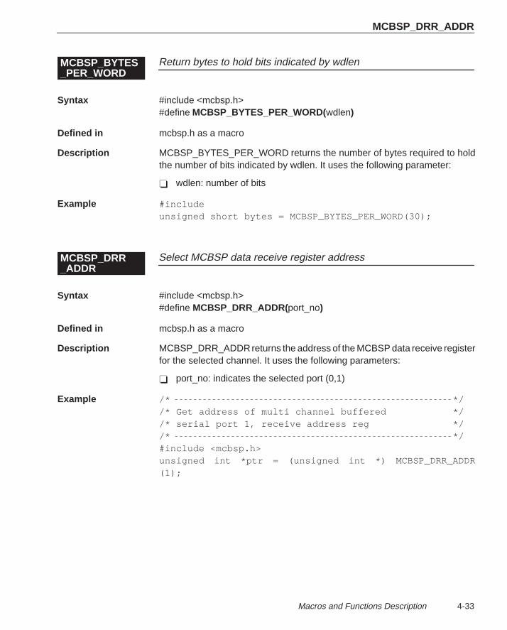
MCBSP_DRR_ADDR
4-33 Macros and Functions Description
Return bytes to hold bits indicated by wdlenMCBSP_BYTES_PER_WORD
Syntax #include <mcbsp.h>#define MCBSP_BYTES_PER_WORD(wdlen)
Defined in mcbsp.h as a macro
Description MCBSP_BYTES_PER_WORD returns the number of bytes required to holdthe number of bits indicated by wdlen. It uses the following parameter:
� wdlen: number of bits
Example #includeunsigned short bytes = MCBSP_BYTES_PER_WORD(30);
Select MCBSP data receive register addressMCBSP_DRR_ADDR
Syntax #include <mcbsp.h>#define MCBSP_DRR_ADDR(port_no)
Defined in mcbsp.h as a macro
Description MCBSP_DRR_ADDR returns the address of the MCBSP data receive registerfor the selected channel. It uses the following parameters:
� port_no: indicates the selected port (0,1)
Example /* *//* Get address of multi channel buffered *//* serial port 1, receive address reg *//* */#include <mcbsp.h>unsigned int *ptr = (unsigned int *) MCBSP_DRR_ADDR(1);
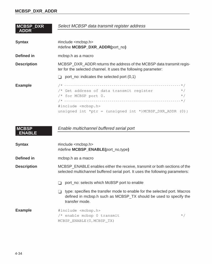
MCBSP_DXR_ADDR
4-34
Select MCBSP data transmit register addressMCBSP_DXR_ADDR
Syntax #include <mcbsp.h>#define MCBSP_DXR_ADDR(port_no)
Defined in mcbsp.h as a macro
Description MCBSP_DXR_ADDR returns the address of the MCBSP data transmit regis-ter for the selected channel. It uses the following parameter:
� port_no: indicates the selected port (0,1)
Example /* *//* Get address of data transmit register *//* for MCBSP port 0. *//* */#include <mcbsp.h>unsigned int *ptr = (unsigned int *)MCBSP_DXR_ADDR (0);
Enable multichannel buffered serial portMCBSP_ENABLE
Syntax #include <mcbsp.h>#define MCBSP_ENABLE( port_no,type)
Defined in mcbsp.h as a macro
Description MCBSP_ENABLE enables either the receive, transmit or both sections of theselected multichannel buffered serial port. It uses the following parameters:
� port_no: selects which McBSP port to enable
� type: specifies the transfer mode to enable for the selected port. Macrosdefined in mcbsp.h such as MCBSP_TX should be used to specify thetransfer mode.
Example #include <mcbsp.h>/* enable mcbsp 0 transmit */MCBSP_ENABLE(0,MCBSP_TX)
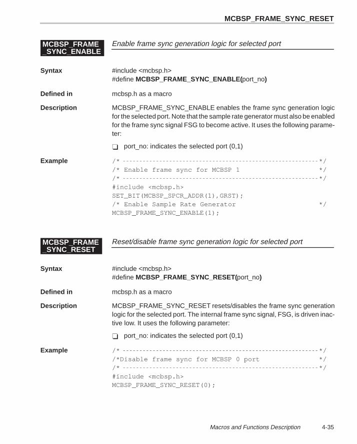
MCBSP_FRAME_SYNC_RESET
4-35 Macros and Functions Description
Enable frame sync generation logic for selected portMCBSP_FRAME_SYNC_ENABLE
Syntax #include <mcbsp.h>#define MCBSP_FRAME_SYNC_ENABLE( port_no)
Defined in mcbsp.h as a macro
Description MCBSP_FRAME_SYNC_ENABLE enables the frame sync generation logicfor the selected port. Note that the sample rate generator must also be enabledfor the frame sync signal FSG to become active. It uses the following parame-ter:
� port_no: indicates the selected port (0,1)
Example /* *//* Enable frame sync for MCBSP 1 *//* */#include <mcbsp.h>SET_BIT(MCBSP_SPCR_ADDR(1),GRST);/* Enable Sample Rate Generator */MCBSP_FRAME_SYNC_ENABLE(1);
Reset/disable frame sync generation logic for selected portMCBSP_FRAME_SYNC_RESET
Syntax #include <mcbsp.h>#define MCBSP_FRAME_SYNC_RESET(port_no)
Defined in mcbsp.h as a macro
Description MCBSP_FRAME_SYNC_RESET resets/disables the frame sync generationlogic for the selected port. The internal frame sync signal, FSG, is driven inac-tive low. It uses the following parameter:
� port_no: indicates the selected port (0,1)
Example /* *//*Disable frame sync for MCBSP 0 port *//* */#include <mcbsp.h>MCBSP_FRAME_SYNC_RESET(0);
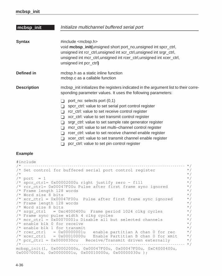
mcbsp_init
4-36
Initialize multichannel buffered serial portmcbsp_init
Syntax #include <mcbsp.h>void mcbsp_init( unsigned short port_no,unsigned int spcr_ctrl,unsigned int rcr_ctrl,unsigned int xcr_ctrl,unsigned int srgr_ctrl,unsigned int mcr_ctrl,unsigned int rcer_ctrl,unsigned int xcer_ctrl,unsigned int pcr_ctrl)
Defined in mcbsp.h as a static inline functionmcbsp.c as a callable function
Description mcbsp_init initializes the registers indicated in the argument list to their corre-sponding parameter values. It uses the following parameters:
� port_no: selects port (0,1)� spcr_ctrl: value to set serial port control register� rcr_ctrl: value to set receive control register� xcr_ctrl: value to set transmit control register� srgr_ctrl: value to set sample rate generator register� mcr_ctrl: value to set multi–channel control register� rcer_ctrl: value to set receive channel enable register� xcer_ctrl: value to set transmit channel enable register� pcr_ctrl: value to set pin control register
Example
#include/* *//* Set control for buffered serial port control register *//* *//* port = 1 *//* spcr_ctrl= 0x00002000u right justify zero – fill *//* rcr_ctrl= 0x00047F00u Pulse after first frame sync ignored *//* Frame length 128 words *//* Word size 8 bits *//* xcr_ctrl = 0x00047F00u Pulse after first frame sync ignored *//* Frame length 128 words *//* Word size 8 bits *//* srgr_ctrl = 0xc4000400u Frame period 1024 clkg cycles *//* Frame sync pulse width 4 clkg cycles *//* mcr_ctrl = 0x00070001u Disable all but selected channels *//* enable blk 0 for receive *//* enable blk 1 for transmit *//* rcer_ctrl = 0x00000001u enable partitian A chan 0 for rec *//* xcer_ctrl = 0x00010000u Enable Partitian B chan 0 for xmit *//* pcr_ctrl = 0x0000030cu Receive/Transmit driven externally *//* */mcbsp_init(1, 0x00002000u, 0x00047F00u, 0x00047F00u, 0xC4000400u,0x00070001u, 0x00000001u, 0x00010000u, 0x00000030u );
MCBSP_IO_ENABLE
4-37 Macros and Functions Description
Take selected port out of general-purpose I/O modeMCBSP_IO_DISABLE
Syntax #include <mcbsp.h>#define MCBSP_IO_DISABLE( port_no)
Defined in mcbsp.h as a macro
Description MCBSP_IO_DISABLE restores the selected port to McBSP operational modefrom the general-purpose I/O mode. It uses the following parameter:
� port_no: indicates the selected port (0,1)
Example /* *//* Take MCBSP 0 out of general purpose I/O *//* mode *//* */#include <mcbsp.h>MCBSP_IO_DISABLE(0);
Place selected port in general-purpose I/O modeMCBSP_IO_ENABLE
Syntax #include <mcbsp.h>#define MCBSP_IO_ENABLE( port_no)
Defined in mcbsp.h as a macro
Description MCBSP_IO_ENABLE places the selected port in general purpose I/O mode.DR and CLKS are general purpose input pins; DX is a general purpose outputpin. FS(R/X), CLK(R/X) are general-purpose I/O pins. MCBSP_IO_ENABLEuses the following parameter:
� port_no: indicates the selected port (0,1)
Example /* *//* Place MCBSP 0 port in general purpose I/O *//* mode *//* */#include <mcbsp.h>MCBSP_IO_ENABLE (0);
MCBSP
4-38
Take selected serial port out of internal loopback modeMCBSP_LOOPBACK_DISABLE
Syntax #include <mcbsp.h>#define MCBSP_LOOPBACK_DISABLE( port_no)
Defined in mcbsp.h as a macro2
Description MCBSP_LOOPBACK_DISABLE takes the selected serial port out of internalloopback mode by resetting the DLB bit in the appropriate serial port configura-tion register. It uses the following parameter:
� port_no: indicates the selected port (0,1)
Example /* *//* Disable loopback mode mode for MCBSP 1 *//* */#include <mcbsp.h>MCBSP_LOOPBACK_DISABLE(1);
Place selected serial port in internal loopback modeMCBSP_LOOPBACK_ENABLE
Syntax #include <mcbsp.h>#define MCBSP_LOOPBACK_ENABLE( port_no)
Defined in mcbsp.h as a macro
Description MCBSP_LOOPBACK_ENABLE places the selected serial port in internalloopback mode by setting the DLB bit in the appropriate serial port configura-tion register. During DLB mode, the DR, FSR, and CLKR are internally con-nected to the DX, FSX and CLKX pins, respectively. MCBSP_LOOP-BACK_ENABLE uses the following parameter:
� port_no: indicates the selected port (0,1)
Example /* *//* Place MCBSP 1 digital loopback mode *//* */#include <mcbsp.h>MCBSP_LOOPBACK_ENABLE(1);
MCBSP_LOOPBACK_DISABLE
MCBSP_PCR_ADDR
4-39 Macros and Functions Description
Select MCBSP multichannel control register addressMCBSP_MCR_ADDR
Syntax #include <mcbsp.h>#define MCBSP_MCR_ADDR(port_no)
Defined in mcbsp.h as a macro
Description MCBSP_MCR_ADDR returns the address of the MCBSP multichannel controlregister for the selected channel. It uses the following parameter:
� port_no: indicates the selected port (0,1)
Example /* *//* Get address of MCBSP 1 multi–channel *//* control register *//* */#include <mcbsp.h>unsigned int *ptr = (unsigned int *)MCBSP_MCR_ADDR(1);
Select MCBSP pin control register addressMCBSP_PCR_ADDR
Syntax #include <mcbsp.h>#define MCBSP_PCR_ADDR(port_no)
Defined in mcbsp.h as a macro
Description MCBSP_PCR_ADDR returns the address of the MCBSP pin control registerfor the selected channel. It uses the following parameter:
� port_no: indicates the selected port (0,1)
Example /* *//* Get address of MCBSP 1 pin control reg *//* */#include <mcbsp.h>unsigned int *ptr = (unsigned int *)MCBSP_PCR_ADDR(1);
MCBSP_RCER_ADDR
4-40
Select MCBSP receive channel enable register addressMCBSP_RCER_ADDR
Syntax #include <mcbsp.h>#define MCBSP_RCER_ADDR(port_no)
Defined in mcbsp.h as a macro
Description MCBSP_RCER_ADDR returns the address of the MCBSP receive channelenable register for the selected channel. It uses the following parameter:
� port_no: indicates the selected port (0,1)
Example /* *//*Get address of MCBSP 1 receive channel enable reg *//* */#include <mcbsp.h>unsigned int *ptr = (unsigned int *)MCBSP_RCER_ADDR(1);
Select MCBSP receive control register addressMCBSP_RCR_ADDR
Syntax #include <mcbsp.h>#define MCBSP_RCR_ADDR(port_no)
Defined in mcbsp.h as a macro
Description This macro function returns the address of the MCBSP receive control registerfor the selected channel. It uses the following parameter:
� port_no: indicates the selected port (0,1)
Example /* *//*Get address of MCBSP 1 receive control register *//* */#include <mcbsp.h>unsigned int *ptr = (unsigned int *)MCBSP_RCR_ADDR(1);
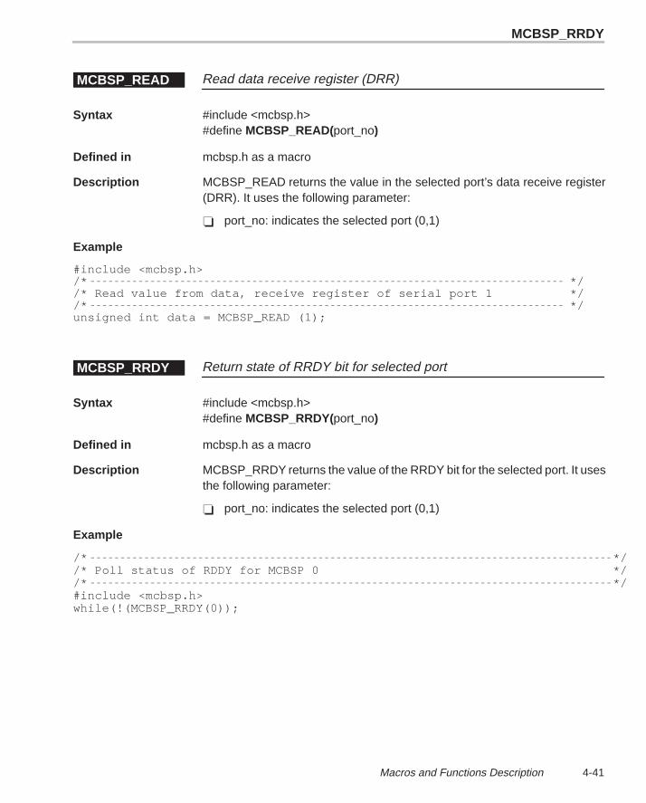
MCBSP_RRDY
4-41 Macros and Functions Description
Read data receive register (DRR)MCBSP_READ
Syntax #include <mcbsp.h>#define MCBSP_READ(port_no)
Defined in mcbsp.h as a macro
Description MCBSP_READ returns the value in the selected port’s data receive register(DRR). It uses the following parameter:
� port_no: indicates the selected port (0,1)
Example
#include <mcbsp.h>/* *//* Read value from data, receive register of serial port 1 *//* */unsigned int data = MCBSP_READ (1);
Return state of RRDY bit for selected portMCBSP_RRDY
Syntax #include <mcbsp.h>#define MCBSP_RRDY(port_no)
Defined in mcbsp.h as a macro
Description MCBSP_RRDY returns the value of the RRDY bit for the selected port. It usesthe following parameter:
� port_no: indicates the selected port (0,1)
Example
/* *//* Poll status of RDDY for MCBSP 0 *//* */#include <mcbsp.h>while(!(MCBSP_RRDY(0));
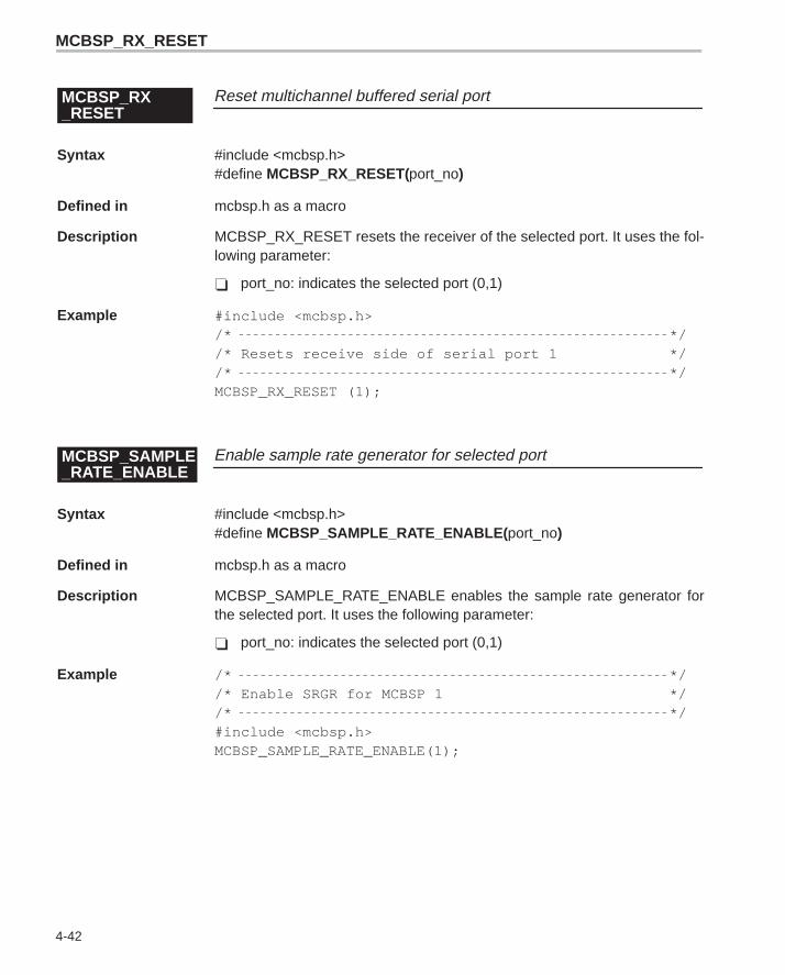
MCBSP_RX_RESET
4-42
Reset multichannel buffered serial portMCBSP_RX_RESET
Syntax #include <mcbsp.h>#define MCBSP_RX_RESET(port_no)
Defined in mcbsp.h as a macro
Description MCBSP_RX_RESET resets the receiver of the selected port. It uses the fol-lowing parameter:
� port_no: indicates the selected port (0,1)
Example #include <mcbsp.h>/* *//* Resets receive side of serial port 1 *//* */MCBSP_RX_RESET (1);
Enable sample rate generator for selected portMCBSP_SAMPLE_RATE_ENABLE
Syntax #include <mcbsp.h>#define MCBSP_SAMPLE_RATE_ENABLE( port_no)
Defined in mcbsp.h as a macro
Description MCBSP_SAMPLE_RATE_ENABLE enables the sample rate generator forthe selected port. It uses the following parameter:
� port_no: indicates the selected port (0,1)
Example /* *//* Enable SRGR for MCBSP 1 *//* */#include <mcbsp.h>MCBSP_SAMPLE_RATE_ENABLE(1);
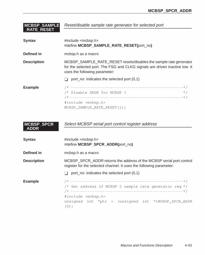
MCBSP_SPCR_ADDR
4-43 Macros and Functions Description
Reset/disable sample rate generator for selected portMCBSP_SAMPLE_RATE_RESET
Syntax #include <mcbsp.h>#define MCBSP_SAMPLE_RATE_RESET( port_no)
Defined in mcbsp.h as a macro
Description MCBSP_SAMPLE_RATE_RESET resets/disables the sample rate generatorfor the selected port. The FSG and CLKG signals are driven inactive low. Ituses the following parameter:
� port_no: indicates the selected port (0,1)
Example /* *//* Disable SRGR for MCBSP 1 *//* */#include <mcbsp.h>MCBSP_SAMPLE_RATE_RESET(1);
Select MCBSP serial port control register addressMCBSP_SPCR_ADDR
Syntax #include <mcbsp.h>#define MCBSP_SPCR_ADDR(port_no)
Defined in mcbsp.h as a macro
Description MCBSP_SPCR_ADDR returns the address of the MCBSP serial port controlregister for the selected channel. It uses the following parameter:
� port_no: indicates the selected port (0,1)
Example /* *//* Get address of MCBSP 0 sample rate generator reg *//* */#include <mcbsp.h>unsigned int *ptr = (unsigned int *)MCBSP_SPCR_ADDR(0);
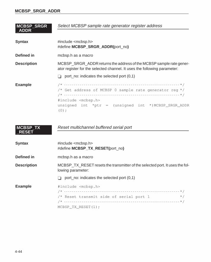
MCBSP_SRGR_ADDR
4-44
Select MCBSP sample rate generator register addressMCBSP_SRGR_ADDR
Syntax #include <mcbsp.h>#define MCBSP_SRGR_ADDR(port_no)
Defined in mcbsp.h as a macro
Description MCBSP_SRGR_ADDR returns the address of the MCBSP sample rate gener-ator register for the selected channel. It uses the following parameter:
� port_no: indicates the selected port (0,1)
Example /* *//* Get address of MCBSP 0 sample rate generator reg *//* */#include <mcbsp.h>unsigned int *ptr = (unsigned int *)MCBSP_SRGR_ADDR(0);
Reset multichannel buffered serial portMCBSP_TX_RESET
Syntax #include <mcbsp.h>#define MCBSP_TX_RESET(port_no)
Defined in mcbsp.h as a macro
Description MCBSP_TX_RESET resets the transmitter of the selected port. It uses the fol-lowing parameter:
� port_no: indicates the selected port (0,1)
Example #include <mcbsp.h>/* *//* Reset transmit side of serial port 1 *//* */MCBSP_TX_RESET(1);
MCBSP_XCER_ADDR
4-45 Macros and Functions Description
Write data transmit register (DXR)MCBSP_WRITE
Syntax #include <mcbsp.h>#define MCBSP_WRITE (port_no,data)
Defined in mcbsp.h as a macro
Description MCBSP_WRITE loads data into the selected port’s data transmit register(DXR). It uses the following parameters:
� port_no: indicates the selected port (0,1)� data: data to be transmitted
Example #include <mcbsp.h>MCBSP_WRITE (1, (unsigned int) ’A’);
Select MCBSP transmit channel enable register addressMCBSP_XCER_ADDR
Syntax #include <mcbsp.h>#define MCBSP_XCER_ADDR(port_no)
Defined in mcbsp.h as a macro
Description MCBSP_XCER_ADDR returns the address of the MCBSP transmit channelenable register for the selected channel. It uses the following parameter:
� port_no: indicates the selected port (0,1)
Example
/* *//* Get address of MCBSP 1 transmit control register *//* */#include <mcbsp.h>unsigned int xcer = MCBSP_XCER_ADDR(1);
MCBSP_XCR_ADDR
4-46
Select MCBSP transmit control register addressMCBSP_XCR_ADDR
Syntax #include <mcbsp.h>#define MCBSP_XCR_ADDR(port_no)
Defined in mcbsp.h as a macro
Description MCBSP_XCR_ADDR returns the address of the MCBSP transmit control reg-ister for the selected channel. It uses the following parameter:
� port_no: indicates the selected port (0,1)
Example /* *//* Get address of MCBSP 1 transmit control register *//* */#include <mcbsp.h>unsigned int *ptr = (unsigned int *)MCBSP_XCR_ADDR (1);
Return state of XRDY bit for selected portMCBSP_XRDY
Syntax #include <mcbsp.h>#define MCBSP_XRDY(port_no)
Defined in mcbsp.h as a macro
Description MCBSP_XRDY returns the value of the XRDY bit for the selected port. It usesthe following parameter:
� port_no: indicates the selected port (0,1)
Example /* *//* Poll status of XRDY for MCBSP 0 *//* */#include <mcbsp.h>while (!(MCBSP_XRDY(0));
REG_WRITE
4-47 Macros and Functions Description
Read memory-mapped registerREG_READ
Syntax #include <regs.h>#define REG_READ(addr)
Defined in regs.h as a macro
Description REG_READ returns the contents of the register whose address is given byaddr. It uses the following parameter:
� addr: address of memory-mapped register to be read.
Example
/* *//* Include timer.h to access timer control register *//* Definitions, macros, and functions, including timer.h *//* Automatically includes regs.h *//* */#include <timer.h>unsigned int count = REG_READ(TIMER0_COUNTER_ADDR);/*Get value of timer counter register */
Write to memory-mapped registerREG_WRITE
Syntax #include <regs.h>#define REG_WRITE(addr,val)
Defined in regs.h as a macro
Description REG_WRITE writes val to the register whose address is given by addr. It usesthe following parameters:
� addr: address of memory-mapped register to write to� val: value to write to register
Example
/* *//* Include timer.h to access timer control register *//* Definitions, macros and functions, including timer.h *//* Automatically includes, regs.h *//* */#include <timer.h>REG_WRITE(TIMER0_PERIOD_ADDR,256);/* Set TIMER 0 period register */
RESET_BIT
4-48
Reset/clear bitRESET_BIT
Syntax #include <regs.h>#define RESET_BIT(addr,bit)
Defined in regs.h as a macro
Description RESET_BIT resets (clears) the indicated bit in the register whose address isgiven by addr. It uses the following parameters:
� addr: address of memory-mapped register/word to access� bit: bit to reset/clear
Example
/* *//* Include hpi.h to gain access to Host Port Interface *//* Register definitions, macros, and functions *//* Including hpi.h, automatically includes, regs.h *//* */RESET_BIT (HPIC_ADDR, DSPINT);
/*Clear HOST to DSP/DMA interrupt bit */
Resets/clears bits in bit fieldRESET_FIELD
Syntax #include <regs.h>#define RESET_FIELD(addr,bit,length)
Defined in regs.h as a macro
Description RESET_FIELD clears the bits within the indicated bit field in the register whoseaddress is given by addr. It uses the following parameters:
� addr: address of memory-mapped register� bit: starting bit of field to reset/clear� length: length of bit field (number of bits)
Example
/* *//* Include intr.h to access interrupt handling macros *//* Functions and register definitions. Including *//* intr.h automatically includes, regs.h *//* */#include <intr.h>
RESET_FIELD(INTR_MULTIPLEX_LOW_ADDR,INTSEL6, INTSEL_SZ);/* Reset interrupt selector interrupt 6 */
SDRAM_INIT
4-49 Macros and Functions Description
Reset/clear bit in named registerRESET_REG_BIT
Syntax #include <regs.h>#define RESET_REG_BIT(reg,bit)
Defined in regs.h as a macro
Description RESET_REG_BIT sets the indicated bit in the named register. It uses the fol-lowing parameters:
� reg: register name (CSR, MCBSP0_SPCR, TIMER0_CTRL,DMA_GCTRL)
� bit: bit in register to reset/clear
Example
/* *//* Include intr.h to access interrupt handling macros *//* Functions and register definitions. Including *//* intr.h automatically includes, regs.h *//* */#include <intr.h>RESET_REG_BIT(IFR,IF4);
/* Reset/clear interrupt flag for CPU interrupt #4 */
Initialize SDRAMSDRAM_INIT
Syntax #include <emif.h>#define SDRAM_INIT( )
Defined in emif.h as a macro
Description SDRAM_INIT causes the EMIF to perform the necessary functions to initializeSDRAM if any of the CE spaces are configured for SDRAM.
Example #include <emif.h> SDRAM_INIT( ) ;
SDRAM_REFRESH_DISABLE
4-50
Disable SDRAM refresh cyclesSDRAM_REFRESH_DISABLE
Syntax #include <emif.h>#define SDRAM_REFRESH_DISABLE( )
Defined in emif.h as a macro
Description SDRAM_REFRESH_DISABLE disables SDRAM refresh cycles for all CEspaces that specify an SDRAM memory type in the MTYPE field of theassociated CE space control register.
Example #include <emif.h>SDRAM_REFRESH_DISABLE( );
Enable SDRAM refresh cyclesSDRAM_REFRESH_ENABLE
Syntax #include <emif.h>#define SDRAM_REFRESH_ENABLE( )
Defined in emif.h as a macro
Description SDRAM_REFRESH_ENABLE enables SDRAM refresh cycles for all CEspaces that specify an SDRAM memory type in the MTYPE field of theassociated CE space control register.
Example #include <emif.h> SDRAM_REFRESH_ENABLE( );
SET_BIT
4-51 Macros and Functions Description
Set SDRAM refresh periodSDRAM_REFRESH_PERIOD
Syntax #include <emif.h>#define SDRAM_REFRESH_PERIOD(val)
Defined in emif.h as a macro
Description SDRAM_REFRESH_PERIOD sets the SDRAM refresh period by assigningthe val parameter to the PERIOD field of the SDRAM timing register. It usesthe following parameter:
� val: value to set SDRAM refresh period in SDRAM timing register. Val indi-cates the number of CLKOUT2 periods (1/2 the CPU clock rate) in the re-fresh cycle.
Example #include <emif.h>SDRAM_REFRESH_PERIOD(2048);
Set bitSET_BIT
Syntax #include <regs.h>#define SET_BIT(addr,bit)
Defined in regs.h as a macro
Description SET_BIT sets the indicated bit to 1 in the register whose address is given byaddr. It uses the following parameter:
� addr: address of memory-mapped register� bit: bit in register to set
Example /* HPI.H automatically includes regs.h */#include <hpi.h>SET_BIT(HPIC_ADDR,HRDY);
SET_REG
4-52
Set value of named registerSET_REG
Syntax #include <regs.h>#define SET_REG(reg,val)
Defined in regs.h as a macro
Description SET_REG sets the value of the named register. It uses the following parame-ters:
� reg: name of memory-mapped register� val: value to assign to register
Example #include <timer.h>/* timer.h automatically includes regs.h */SET_REG(TIMER0_PERIOD,256);
Set bit in named registerSET_REG_BIT
Syntax #include <regs.h>#define SET_REG_BIT(reg,bit)
Defined in regs.h as a macro
Description SET_REG_BIT sets the indicated bit in the named register.
� reg: name of peripheral/memory-mapped control register� bit: bit in register to be set
Example #include <hpi.h>/* hpi.h automatically includes regs.h */SET_REG_BIT(HPIC,HRDY);

TIMER_CLK_EXTERNAL
4-53 Macros and Functions Description
Check for availability of timer channelTIMER_AVAILABLE
Syntax #include <timer.h>#define TIMER_AVAILABLE( chan)
Defined in timer.h as a macro
Description TIMER_AVAILABLE checks the status of the specified channel to see if it isavailable for use. It uses the following parameter:
� chan: channel selector (0,1)
Example #include <timer.h>if (TIMER_AVAILABLE(0)) timer_init(0, 0x1, 0xffff);
Select external clock source timer for channelTIMER_CLK_EXTERNAL
Syntax #include <timer.h>#define TIMER_CLK_EXTERNAL( chan)
Defined in timer.h as a macro
Description TIMER_CLK_EXTERNAL selects the external clock source for the specifiedtimer channel. It uses the following parameter:
� chan: channel selector (0,1)
Example#include <timer.h>TIMER_CLK_EXTERNAL(1); /* TIMER 1 driven by external clock source */
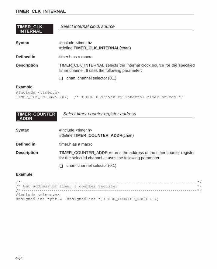
TIMER_CLK_INTERNAL
4-54
Select internal clock sourceTIMER_CLK_INTERNAL
Syntax #include <timer.h>#define TIMER_CLK_INTERNAL( chan)
Defined in timer.h as a macro
Description TIMER_CLK_INTERNAL selects the internal clock source for the specifiedtimer channel. It uses the following parameter:
� chan: channel selector (0,1)
Example#include <timer.h>TIMER_CLK_INTERNAL(0); /* TIMER 0 driven by internal clock source */
Select timer counter register addressTIMER_COUNTER_ADDR
Syntax #include <timer.h>#define TIMER_COUNTER_ADDR(chan)
Defined in timer.h as a macro
Description TIMER_COUNTER_ADDR returns the address of the timer counter registerfor the selected channel. It uses the following parameter:
� chan: channel selector (0,1)
Example
/* *//* Get address of timer 1 counter register *//* */#include <timer.h>unsigned int *ptr = (unsigned int *)TIMER_COUNTER_ADDR (1);
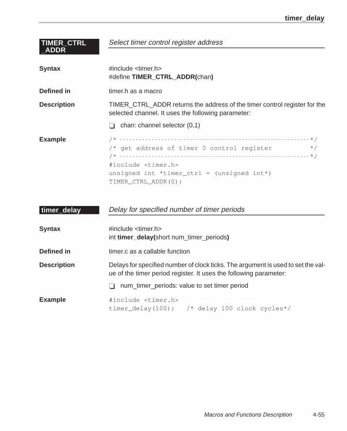
timer_delay
4-55 Macros and Functions Description
Select timer control register addressTIMER_CTRL_ADDR
Syntax #include <timer.h>#define TIMER_CTRL_ADDR(chan)
Defined in timer.h as a macro
Description TIMER_CTRL_ADDR returns the address of the timer control register for theselected channel. It uses the following parameter:
� chan: channel selector (0,1)
Example /* *//* get address of timer 0 control register *//* */#include <timer.h>unsigned int *timer_ctrl = (unsigned int*)TIMER_CTRL_ADDR(0);
Delay for specified number of timer periodstimer_delay
Syntax #include <timer.h>int timer_delay( short num_timer_periods)
Defined in timer.c as a callable function
Description Delays for specified number of clock ticks. The argument is used to set the val-ue of the timer period register. It uses the following parameter:
� num_timer_periods: value to set timer period
Example #include <timer.h>timer_delay(100); /* delay 100 clock cycles*/
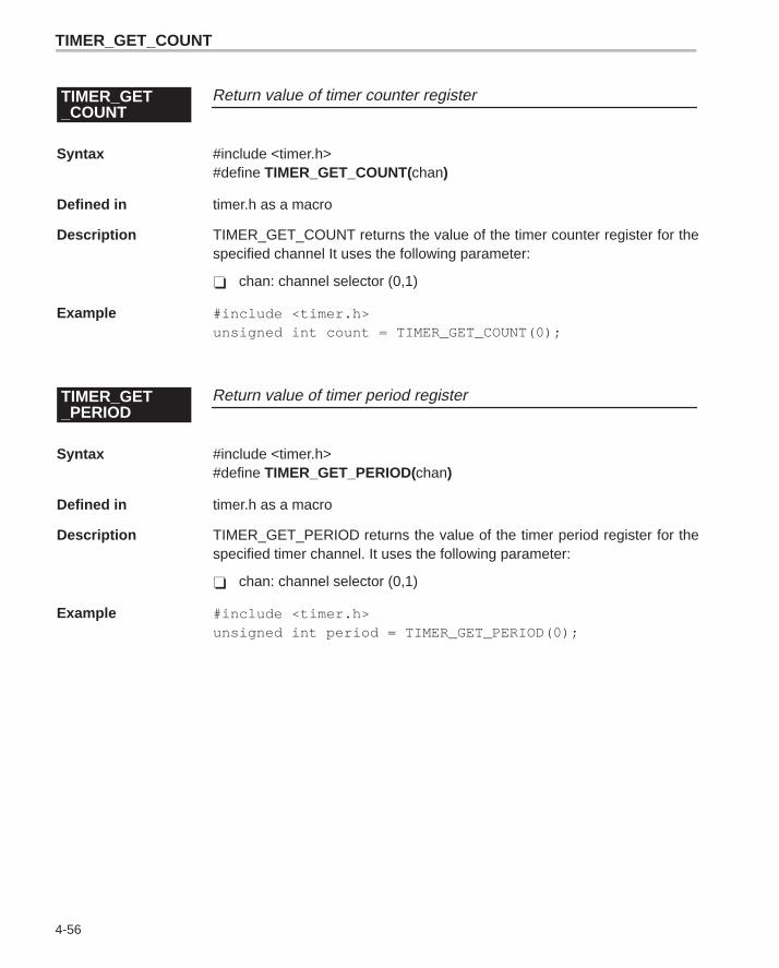
TIMER_GET_COUNT
4-56
Return value of timer counter registerTIMER_GET_COUNT
Syntax #include <timer.h>#define TIMER_GET_COUNT(chan)
Defined in timer.h as a macro
Description TIMER_GET_COUNT returns the value of the timer counter register for thespecified channel It uses the following parameter:
� chan: channel selector (0,1)
Example #include <timer.h>unsigned int count = TIMER_GET_COUNT(0);
Return value of timer period registerTIMER_GET_PERIOD
Syntax #include <timer.h>#define TIMER_GET_PERIOD(chan)
Defined in timer.h as a macro
Description TIMER_GET_PERIOD returns the value of the timer period register for thespecified timer channel. It uses the following parameter:
� chan: channel selector (0,1)
Example #include <timer.h>unsigned int period = TIMER_GET_PERIOD(0);
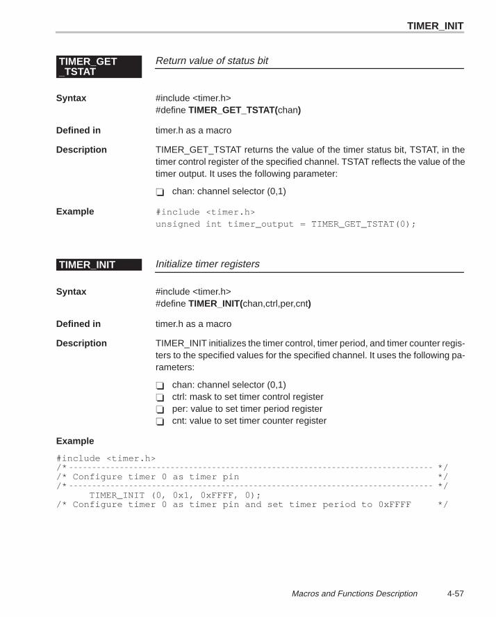
TIMER_INIT
4-57 Macros and Functions Description
Return value of status bitTIMER_GET_TSTAT
Syntax #include <timer.h>#define TIMER_GET_TSTAT(chan)
Defined in timer.h as a macro
Description TIMER_GET_TSTAT returns the value of the timer status bit, TSTAT, in thetimer control register of the specified channel. TSTAT reflects the value of thetimer output. It uses the following parameter:
� chan: channel selector (0,1)
Example #include <timer.h>unsigned int timer_output = TIMER_GET_TSTAT(0);
Initialize timer registersTIMER_INIT
Syntax #include <timer.h>#define TIMER_INIT(chan,ctrl,per,cnt)
Defined in timer.h as a macro
Description TIMER_INIT initializes the timer control, timer period, and timer counter regis-ters to the specified values for the specified channel. It uses the following pa-rameters:
� chan: channel selector (0,1)� ctrl: mask to set timer control register� per: value to set timer period register� cnt: value to set timer counter register
Example
#include <timer.h>/* *//* Configure timer 0 as timer pin *//* */
TIMER_INIT (0, 0x1, 0xFFFF, 0);/* Configure timer 0 as timer pin and set timer period to 0xFFFF */
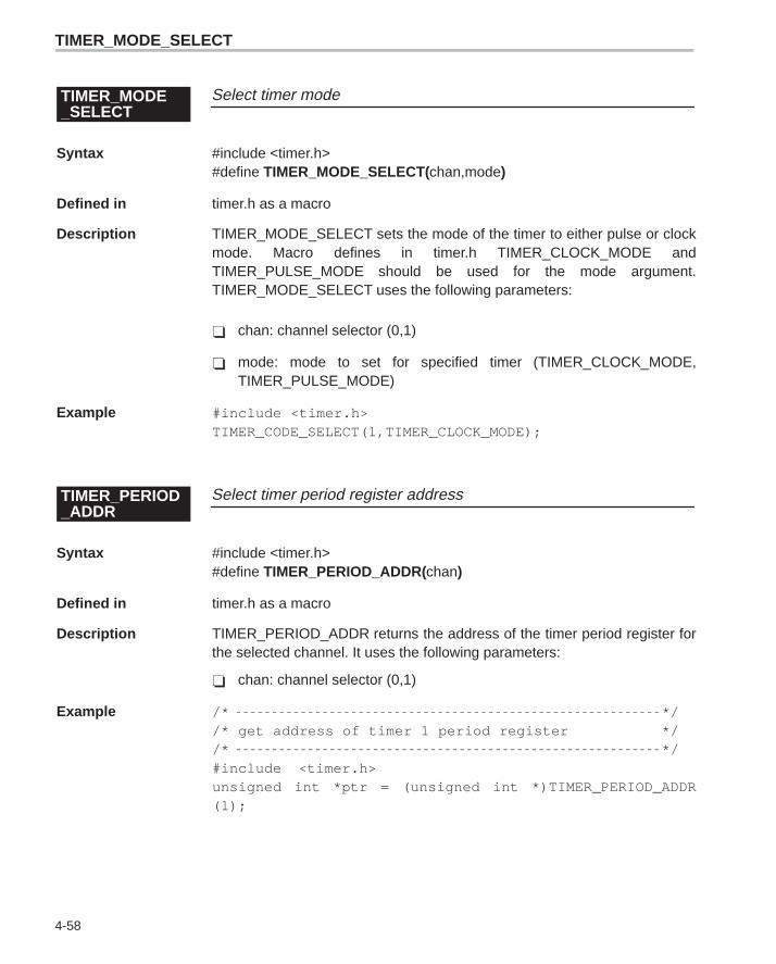
TIMER_MODE_SELECT
4-58
Select timer modeTIMER_MODE_SELECT
Syntax #include <timer.h>#define TIMER_MODE_SELECT(chan,mode)
Defined in timer.h as a macro
Description TIMER_MODE_SELECT sets the mode of the timer to either pulse or clockmode. Macro defines in timer.h TIMER_CLOCK_MODE andTIMER_PULSE_MODE should be used for the mode argument.TIMER_MODE_SELECT uses the following parameters:
� chan: channel selector (0,1)
� mode: mode to set for specified timer (TIMER_CLOCK_MODE,TIMER_PULSE_MODE)
Example #include <timer.h>TIMER_CODE_SELECT(1,TIMER_CLOCK_MODE);
Select timer period register addressTIMER_PERIOD_ADDR
Syntax #include <timer.h>#define TIMER_PERIOD_ADDR(chan)
Defined in timer.h as a macro
Description TIMER_PERIOD_ADDR returns the address of the timer period register forthe selected channel. It uses the following parameters:
� chan: channel selector (0,1)
Example /* *//* get address of timer 1 period register *//* */#include <timer.h>unsigned int *ptr = (unsigned int *)TIMER_PERIOD_ADDR(1);
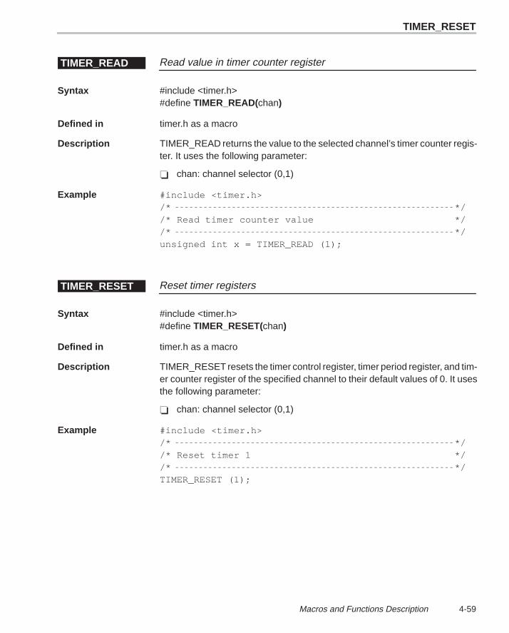
TIMER_RESET
4-59 Macros and Functions Description
Read value in timer counter registerTIMER_READ
Syntax #include <timer.h>#define TIMER_READ(chan)
Defined in timer.h as a macro
Description TIMER_READ returns the value to the selected channel’s timer counter regis-ter. It uses the following parameter:
� chan: channel selector (0,1)
Example #include <timer.h>/* *//* Read timer counter value *//* */unsigned int x = TIMER_READ (1);
Reset timer registersTIMER_RESET
Syntax #include <timer.h>#define TIMER_RESET(chan)
Defined in timer.h as a macro
Description TIMER_RESET resets the timer control register, timer period register, and tim-er counter register of the specified channel to their default values of 0. It usesthe following parameter:
� chan: channel selector (0,1)
Example #include <timer.h>/* *//* Reset timer 1 *//* */TIMER_RESET (1);
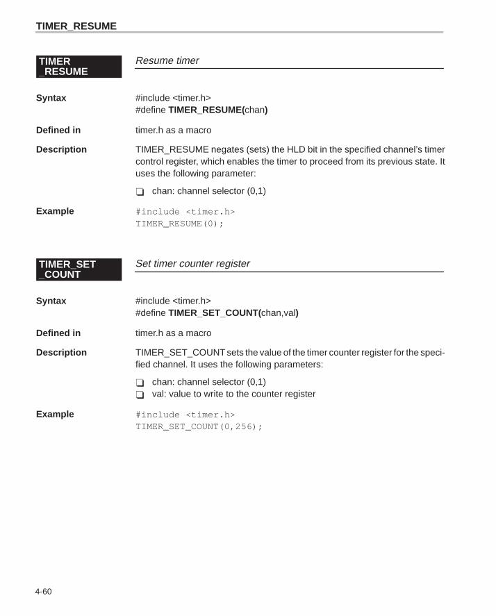
TIMER
4-60
Resume timerTIMER_RESUME
Syntax #include <timer.h>#define TIMER_RESUME(chan)
Defined in timer.h as a macro
Description TIMER_RESUME negates (sets) the HLD bit in the specified channel’s timercontrol register, which enables the timer to proceed from its previous state. Ituses the following parameter:
� chan: channel selector (0,1)
Example #include <timer.h>TIMER_RESUME(0);
Set timer counter registerTIMER_SET_COUNT
Syntax #include <timer.h>#define TIMER_SET_COUNT(chan,val)
Defined in timer.h as a macro
Description TIMER_SET_COUNT sets the value of the timer counter register for the speci-fied channel. It uses the following parameters:
� chan: channel selector (0,1)� val: value to write to the counter register
Example #include <timer.h>TIMER_SET_COUNT(0,256);
TIMER_RESUME
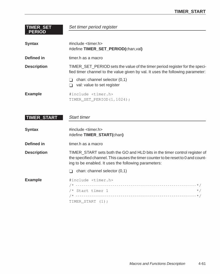
TIMER_START
4-61 Macros and Functions Description
Set timer period registerTIMER_SET_PERIOD
Syntax #include <timer.h>#define TIMER_SET_PERIOD(chan,val)
Defined in timer.h as a macro
Description TIMER_SET_PERIOD sets the value of the timer period register for the speci-fied timer channel to the value given by val. It uses the following parameter:
� chan: channel selector (0,1)� val: value to set register
Example #include <timer.h>TIMER_SET_PERIOD(1,1024);
Start timerTIMER_START
Syntax #include <timer.h>#define TIMER_START(chan)
Defined in timer.h as a macro
Description TIMER_START sets both the GO and HLD bits in the timer control register ofthe specified channel. This causes the timer counter to be reset to 0 and count-ing to be enabled. It uses the following parameters:
� chan: channel selector (0,1)
Example #include <timer.h>/* *//* Start timer 1 *//* */TIMER_START (1);
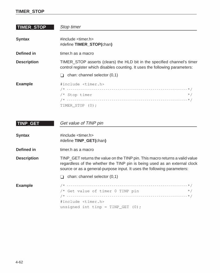
TIMER_STOP
4-62
Stop timerTIMER_STOP
Syntax #include <timer.h>#define TIMER_STOP(chan)
Defined in timer.h as a macro
Description TIMER_STOP asserts (clears) the HLD bit in the specified channel’s timercontrol register which disables counting. It uses the following parameters:
� chan: channel selector (0,1)
Example #include <timer.h>/* *//* Stop timer *//* */TIMER_STOP (0);
Get value of TINP pinTINP_GET
Syntax #include <timer.h>#define TINP_GET(chan)
Defined in timer.h as a macro
Description TINP_GET returns the value on the TINP pin. This macro returns a valid valueregardless of the whether the TINP pin is being used as an external clocksource or as a general-purpose input. It uses the following parameters:
� chan: channel selector (0,1)
Example /* *//* Get value of timer 0 TINP pin *//* */#include <timer.h>unsigned int tinp = TINP_GET (0);
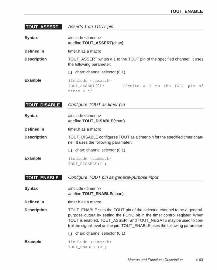
TOUT_ENABLE
4-63 Macros and Functions Description
Asserts 1 on TOUT pinTOUT_ASSERT
Syntax #include <timer.h>#define TOUT_ASSERT(chan)
Defined in timer.h as a macro
Description TOUT_ASSERT writes a 1 to the TOUT pin of the specified channel. It usesthe following parameter:
� chan: channel selector (0,1)
Example #include <timer.h>TOUT_ASSERT(0); /*Write a 1 to the TOUT pin oftimer 0 */
Configure TOUT as timer pinTOUT_DISABLE
Syntax #include <timer.h>#define TOUT_DISABLE( chan)
Defined in timer.h as a macro
Description TOUT_DISABLE configures TOUT as a timer pin for the specified timer chan-nel. It uses the following parameter:
� chan: channel selector (0,1)
Example #include <timer.h>TOUT_DISABLE(1);
Configure TOUT pin as general-purpose inputTOUT_ENABLE
Syntax #include <timer.h>#define TOUT_ENABLE( chan)
Defined in timer.h as a macro
Description TOUT_ENABLE sets the TOUT pin of the selected channel to be a general-purpose output by setting the FUNC bit in the timer control register. WhenTOUT is enabled, TOUT_ASSERT and TOUT_NEGATE may be used to con-trol the signal level on the pin. TOUT_ENABLE uses the following parameter:
� chan: channel selector (0,1)
Example #include <timer.h>TOUT_ENABLE (0);
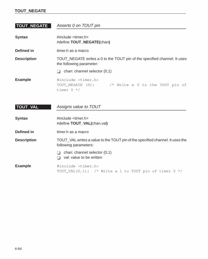
TOUT_NEGATE
4-64
Asserts 0 on TOUT pinTOUT_NEGATE
Syntax #include <timer.h>#define TOUT_NEGATE(chan)
Defined in timer.h as a macro
Description TOUT_NEGATE writes a 0 to the TOUT pin of the specified channel. It usesthe following parameter:
� chan: channel selector (0,1)
Example #include <timer.h>TOUT_NEGATE (0); /* Write a 0 to the TOUT pin oftimer 0 */
Assigns value to TOUTTOUT_VAL
Syntax #include <timer.h>#define TOUT_VAL(chan,val)
Defined in timer.h as a macro
Description TOUT_VAL writes a value to the TOUT pin of the specified channel. It uses thefollowing parameters:
� chan: channel selector (0,1)� val: value to be written
Example #include <timer.h>TOUT_VAL(0,1); /* Write a 1 to TOUT pin of timer 0 */
A-1
Appendix A
Source File Listing
This appendix provides the entire code listing for each source file containedin the ’C6x peripheral support library. However, the code provided to you maybe a more recent version than the one that is listed here. For more informationon the source files and the macros and functions that comprise them, seeChapter 2.
Topic Page
A.1 Header Files A-2. . . . . . . . . . . . . . . . . . . . . . . . . . . . . . . . . . . . . . . . . . . . . . . . . .
A.2 C and Assembly Files A-39. . . . . . . . . . . . . . . . . . . . . . . . . . . . . . . . . . . . . . . .
Appendix A
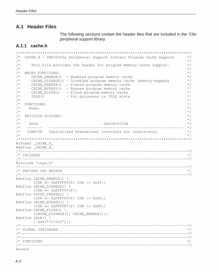
Header Files
A-2
A.1 Header FilesThe following sections contain the header files that are included in the ’C6xperipheral support library.
A.1.1 cache.h
/******************************************************************************//* CACHE.H – TMS320C6x Peripheral Support Library Program Cache Support *//* *//* This file provides the header for program memory cache support. *//* *//* MACRO FUNCTIONS: *//* CACHE_ENABLE() – Enables program memory cache *//* CACHE_DISABLE() – Disables program memory cache (memory–mapped) *//* CACHE_FREEZE() – Freeze program memory cache *//* CACHE_BYPASS() – Bypass program memory cache *//* CACHE_FLUSH() – Flush program memory cache *//* IDLE() – Put processor in IDLE state *//* *//* FUNCTIONS: *//* None. *//* *//* REVISION HISTORY: *//* *//* DATE DESCRIPTION *//* ––––––– ––––––––––––––––––––––––––––––––––––––––––––––––––––––––––––– *//* 11MAY98 Capitalized hexadecimal constants for consistency. *//* *//******************************************************************************/#ifndef _CACHE_H_#define _CACHE_H_/*––––––––––––––––––––––––––––––––––––––––––––––––––––––––––––––––––––––––––––*//* INCLUDES *//*––––––––––––––––––––––––––––––––––––––––––––––––––––––––––––––––––––––––––––*/#include ”regs.h”/*––––––––––––––––––––––––––––––––––––––––––––––––––––––––––––––––––––––––––––*//* DEFINES AND MACROS *//*––––––––––––––––––––––––––––––––––––––––––––––––––––––––––––––––––––––––––––*/#define CACHE_ENABLE() \ {CSR &= 0xFFFFFF1F; CSR |= 0x40;}#define CACHE_DISABLE() \ {CSR &= 0xFFFFFF1F;}#define CACHE_FREEZE() \ {CSR &= 0xFFFFFF1F; CSR |= 0x60;}#define CACHE_BYPASS() \ {CSR &= 0xFFFFFF1F; CSR |= 0x80;}#define CACHE_FLUSH() \ {CACHE_DISABLE(); CACHE_ENABLE();}#define IDLE() \ { asm(”\tidle”);}/*––––––––––––––––––––––––––––––––––––––––––––––––––––––––––––––––––––––––––––*//* GLOBAL VARIABLES *//*––––––––––––––––––––––––––––––––––––––––––––––––––––––––––––––––––––––––––––*//*––––––––––––––––––––––––––––––––––––––––––––––––––––––––––––––––––––––––––––*//* FUNCTIONS *//*––––––––––––––––––––––––––––––––––––––––––––––––––––––––––––––––––––––––––––*/#endif
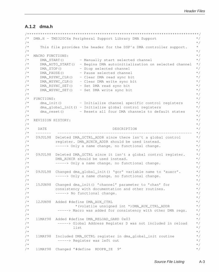
Header Files
A-3Source File Listing
A.1.2 dma.h
/******************************************************************************//* DMA.H – TMS320C6x Peripheral Support Library DMA Support *//* *//* This file provides the header for the DSP’s DMA controller support. */* *//* MACRO FUNCTIONS: *//* DMA_START() – Manually start selected channel *//* DMA_AUTO_START() – Begins DMA autoinitialization on selected channel *//* DMA_STOP() – Stop selected channel *//* DMA_PAUSE() – Pause selected channel *//* DMA_RSYNC_CLR() – Clear DMA read sync bit *//* DMA_WSYNC_CLR() – Clear DMA write sync bit *//* DMA_RSYNC_SET() – Set DMA read sync bit *//* DMA_WSYNC_SET() – Set DMA write sync bit *//* *//* FUNCTIONS: *//* dma_init() – Initialize channel specific control registers *//* dma_global_init() – Initialize global control registers *//* dma_reset() – Resets all four DMA channels to default states *//* *//* REVISION HISTORY: *//* *//* DATE DESCRIPTION *//* ––––––– ––––––––––––––––––––––––––––––––––––––––––––––––––––––––––––– *//* 09JUL98 Deleted DMA_GCTRL_ADDR since there isn’t a global control *//* register. DMA_AUXCR_ADDR should be used instead. *//* –––––> Only a name change, no functional change. *//* *//* 09JUL98 Deleted DMA_GCTRL since it isn’t a global control register. *//* DMA_AUXCR should be used instead. *//* –––––> Only a name change, no functional change. *//* *//* 09JUL98 Changed dma_global_init() “gcr” variable name to “auxcr”. *//* –––––> Only a name change, no functional change. *//* *//* 15JUN98 Changed dma_init() ”channel” parameter to ”chan” for *//* consistency with documentation and other routines. *//* –––––> No functional change. *//* *//* 12JUN98 Added #define DMA_AUX_CTRL *//* *(volatile unsigned int *)DMA_AUX_CTRL_ADDR *//* –––––> Macro was added for consistency with other DMA regs. *//* *//* 11MAY98 Added #define DMA_RELOAD_GARD 0x03 *//* –––––> Global Address Register D was not included in reload *//* list *//* *//* 11MAY98 Included DMA_GCTRL register in dma_global_init routine *//* –––––> Register was left out *//* *//* 11MAY98 Changed ”#define RDOPR_IE 9” */
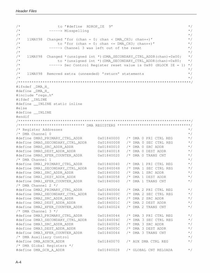
Header Files
A-4
/* to ”#define RDROP_IE 9” *//* –––––> Misspelling *//* *//* 11MAY98 Changed ”for (chan = 0; chan < DMA_CH3; chan++)” *//* to ”for (chan = 0; chan <= DMA_CH3; chan++)” *//* –––––> Channel 3 was left out of the reset *//* *//* 11MAY98 Changed *(unsigned int *)(DMA_SECONDARY_CTRL_ADDR(chan)=0x00; *//* to *(unsigned int *)(DMA_SECONDARY_CTRL_ADDR(chan)=0x80; *//* –––––> Sec Control Register reset value is 0x80 (BLOCK IE = 1) *//* *//* 11MAY98 Removed extra (unneeded) ”return” statements *//* *//******************************************************************************/#ifndef _DMA_H_#define _DMA_H_#include ”regs.h”#ifdef _INLINE#define __INLINE static inline#else#define __INLINE#endif/******************************************************************************//****************************** DMA REGISTERS *********************************//* Register Addresses *//* DMA Channel 0 */#define DMA0_PRIMARY_CTRL_ADDR 0x01840000 /* DMA 0 PRI CTRL REG */#define DMA0_SECONDARY_CTRL_ADDR 0x01840008 /* DMA 0 SEC CTRL REG */#define DMA0_SRC_ADDR_ADDR 0x01840010 /* DMA 0 SRC ADDR */#define DMA0_DEST_ADDR_ADDR 0x01840018 /* DMA 0 DEST ADDR */#define DMA0_XFER_COUNTER_ADDR 0x01840020 /* DMA 0 TRANS CNT *//* DMA Channel 1 */#define DMA1_PRIMARY_CTRL_ADDR 0x01840040 /* DMA 1 PRI CTRL REG */#define DMA1_SECONDARY_CTRL_ADDR 0x01840048 /* DMA 1 SEC CTRL REG */#define DMA1_SRC_ADDR_ADDR 0x01840050 /* DMA 1 SRC ADDR */#define DMA1_DEST_ADDR_ADDR 0x01840058 /* DMA 1 DEST ADDR */#define DMA1_XFER_COUNTER_ADDR 0x01840060 /* DMA 1 TRANS CNT *//* DMA Channel 2 */#define DMA2_PRIMARY_CTRL_ADDR 0x01840004 /* DMA 2 PRI CTRL REG */#define DMA2_SECONDARY_CTRL_ADDR 0x0184000C /* DMA 2 SEC CTRL REG */#define DMA2_SRC_ADDR_ADDR 0x01840014 /* DMA 2 SRC ADDR */#define DMA2_DEST_ADDR_ADDR 0x0184001C /* DMA 2 DEST ADDR */#define DMA2_XFER_COUNTER_ADDR 0x01840024 /* DMA 2 TRANS CNT *//* DMA Channel 3 */#define DMA3_PRIMARY_CTRL_ADDR 0x01840044 /* DMA 3 PRI CTRL REG */#define DMA3_SECONDARY_CTRL_ADDR 0x0184004C /* DMA 3 SEC CTRL REG */#define DMA3_SRC_ADDR_ADDR 0x01840054 /* DMA 3 SRC ADDR */#define DMA3_DEST_ADDR_ADDR 0x0184005C /* DMA 3 DEST ADDR */#define DMA3_XFER_COUNTER_ADDR 0x01840064 /* DMA 3 TRANS CNT *//* DMA Auxiliary Control */#define DMA_AUXCR_ADDR 0x01840070 /* AUX DMA CTRL REG *//* DMA Global Registers */#define DMA_GCR_A_ADDR 0x01840028 /* GLOBAL CNT RELOADA */
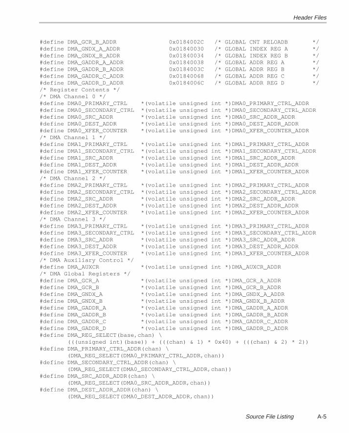
Header Files
A-5Source File Listing
#define DMA_GCR_B_ADDR 0x0184002C /* GLOBAL CNT RELOADB */#define DMA_GNDX_A_ADDR 0x01840030 /* GLOBAL INDEX REG A */#define DMA_GNDX_B_ADDR 0x01840034 /* GLOBAL INDEX REG B */#define DMA_GADDR_A_ADDR 0x01840038 /* GLOBAL ADDR REG A */#define DMA_GADDR_B_ADDR 0x0184003C /* GLOBAL ADDR REG B */#define DMA_GADDR_C_ADDR 0x01840068 /* GLOBAL ADDR REG C */#define DMA_GADDR_D_ADDR 0x0184006C /* GLOBAL ADDR REG D *//* Register Contents *//* DMA Channel 0 */#define DMA0_PRIMARY_CTRL *(volatile unsigned int *)DMA0_PRIMARY_CTRL_ADDR#define DMA0_SECONDARY_CTRL *(volatile unsigned int *)DMA0_SECONDARY_CTRL_ADDR#define DMA0_SRC_ADDR *(volatile unsigned int *)DMA0_SRC_ADDR_ADDR#define DMA0_DEST_ADDR *(volatile unsigned int *)DMA0_DEST_ADDR_ADDR#define DMA0_XFER_COUNTER *(volatile unsigned int *)DMA0_XFER_COUNTER_ADDR/* DMA Channel 1 */#define DMA1_PRIMARY_CTRL *(volatile unsigned int *)DMA1_PRIMARY_CTRL_ADDR#define DMA1_SECONDARY_CTRL *(volatile unsigned int *)DMA1_SECONDARY_CTRL_ADDR#define DMA1_SRC_ADDR *(volatile unsigned int *)DMA1_SRC_ADDR_ADDR#define DMA1_DEST_ADDR *(volatile unsigned int *)DMA1_DEST_ADDR_ADDR#define DMA1_XFER_COUNTER *(volatile unsigned int *)DMA1_XFER_COUNTER_ADDR/* DMA Channel 2 */#define DMA2_PRIMARY_CTRL *(volatile unsigned int *)DMA2_PRIMARY_CTRL_ADDR#define DMA2_SECONDARY_CTRL *(volatile unsigned int *)DMA2_SECONDARY_CTRL_ADDR#define DMA2_SRC_ADDR *(volatile unsigned int *)DMA2_SRC_ADDR_ADDR#define DMA2_DEST_ADDR *(volatile unsigned int *)DMA2_DEST_ADDR_ADDR#define DMA2_XFER_COUNTER *(volatile unsigned int *)DMA2_XFER_COUNTER_ADDR/* DMA Channel 3 */#define DMA3_PRIMARY_CTRL *(volatile unsigned int *)DMA3_PRIMARY_CTRL_ADDR#define DMA3_SECONDARY_CTRL *(volatile unsigned int *)DMA3_SECONDARY_CTRL_ADDR#define DMA3_SRC_ADDR *(volatile unsigned int *)DMA3_SRC_ADDR_ADDR#define DMA3_DEST_ADDR *(volatile unsigned int *)DMA3_DEST_ADDR_ADDR#define DMA3_XFER_COUNTER *(volatile unsigned int *)DMA3_XFER_COUNTER_ADDR/* DMA Auxiliary Control */#define DMA_AUXCR *(volatile unsigned int *)DMA_AUXCR_ADDR/* DMA Global Registers */#define DMA_GCR_A *(volatile unsigned int *)DMA_GCR_A_ADDR#define DMA_GCR_B *(volatile unsigned int *)DMA_GCR_B_ADDR#define DMA_GNDX_A *(volatile unsigned int *)DMA_GNDX_A_ADDR#define DMA_GNDX_B *(volatile unsigned int *)DMA_GNDX_B_ADDR#define DMA_GADDR_A *(volatile unsigned int *)DMA_GADDR_A_ADDR#define DMA_GADDR_B *(volatile unsigned int *)DMA_GADDR_B_ADDR#define DMA_GADDR_C *(volatile unsigned int *)DMA_GADDR_C_ADDR#define DMA_GADDR_D *(volatile unsigned int *)DMA_GADDR_D_ADDR#define DMA_REG_SELECT(base,chan) \ (((unsigned int)(base)) + (((chan) & 1) * 0x40) + (((chan) & 2) * 2))#define DMA_PRIMARY_CTRL_ADDR(chan) \ (DMA_REG_SELECT(DMA0_PRIMARY_CTRL_ADDR,chan))#define DMA_SECONDARY_CTRL_ADDR(chan) \ (DMA_REG_SELECT(DMA0_SECONDARY_CTRL_ADDR,chan))#define DMA_SRC_ADDR_ADDR(chan) \ (DMA_REG_SELECT(DMA0_SRC_ADDR_ADDR,chan))#define DMA_DEST_ADDR_ADDR(chan) \ (DMA_REG_SELECT(DMA0_DEST_ADDR_ADDR,chan))
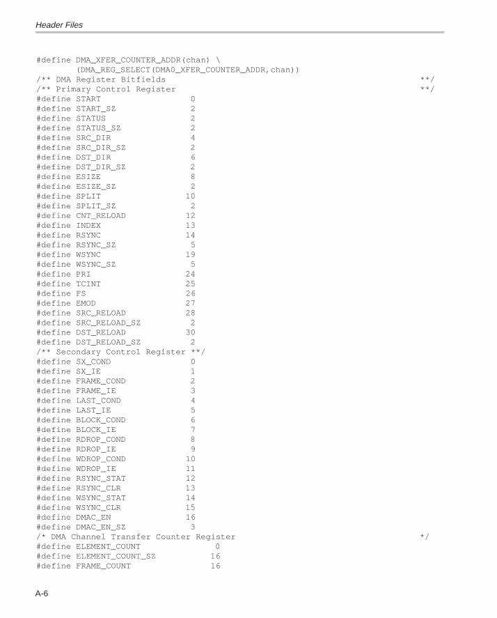
Header Files
A-6
#define DMA_XFER_COUNTER_ADDR(chan) \ (DMA_REG_SELECT(DMA0_XFER_COUNTER_ADDR,chan))/** DMA Register Bitfields **//** Primary Control Register **/#define START 0#define START_SZ 2#define STATUS 2#define STATUS_SZ 2#define SRC_DIR 4#define SRC_DIR_SZ 2#define DST_DIR 6#define DST_DIR_SZ 2#define ESIZE 8#define ESIZE_SZ 2#define SPLIT 10#define SPLIT_SZ 2#define CNT_RELOAD 12#define INDEX 13#define RSYNC 14#define RSYNC_SZ 5#define WSYNC 19#define WSYNC_SZ 5#define PRI 24#define TCINT 25#define FS 26#define EMOD 27#define SRC_RELOAD 28#define SRC_RELOAD_SZ 2#define DST_RELOAD 30#define DST_RELOAD_SZ 2/** Secondary Control Register **/#define SX_COND 0#define SX_IE 1#define FRAME_COND 2#define FRAME_IE 3#define LAST_COND 4#define LAST_IE 5#define BLOCK_COND 6#define BLOCK_IE 7#define RDROP_COND 8#define RDROP_IE 9#define WDROP_COND 10#define WDROP_IE 11#define RSYNC_STAT 12#define RSYNC_CLR 13#define WSYNC_STAT 14#define WSYNC_CLR 15#define DMAC_EN 16#define DMAC_EN_SZ 3/* DMA Channel Transfer Counter Register */#define ELEMENT_COUNT 0#define ELEMENT_COUNT_SZ 16#define FRAME_COUNT 16
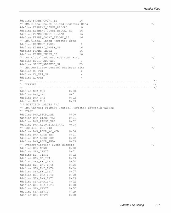
Header Files
A-7Source File Listing
#define FRAME_COUNT_SZ 16/* DMA Global Count Reload Register Bits */#define ELEMENT_COUNT_RELOAD 0#define ELEMENT_COUNT_RELOAD_SZ 16#define FRAME_COUNT_RELOAD 16#define FRAME_COUNT_RELOAD_SZ 16/* DMA Global Index Register Bits */#define ELEMENT_INDEX 0#define ELEMENT_INDEX_SZ 16#define FRAME_INDEX 16#define FRAME_INDEX_SZ 16/* DMA Global Address Register Bits */#define SPLIT_ADDRESS 3#define SPLIT_ADDRESS_SZ 29/* DMA Auxiliary Control Register Bits */#define CH_PRI 0#define CH_PRI_SZ 4#define AUXPRI 4/*––––––––––––––––––––––––––––––––––––––––––––––––––––––––––––––––––––––––––––*//* DEFINES *//*––––––––––––––––––––––––––––––––––––––––––––––––––––––––––––––––––––––––––––*/#define DMA_CH0 0x00#define DMA_CH1 0x01#define DMA_CH2 0x02#define DMA_CH3 0x03/** BITFIELD VALUES **//* DMA Channel Primary Control Register bitfield values *//* START */#define DMA_STOP_VAL 0x00#define DMA_START_VAL 0x01#define DMA_PAUSE_VAL 0x02#define DMA_AUTO_START_VAL 0x03/* SRC DIR, DST DIR */#define DMA_ADDR_NO_MOD 0x00#define DMA_ADDR_INC 0x01#define DMA_ADDR_DEC 0x02#define DMA_ADDR_INDX 0x03/* Synchronization Event Numbers */#define SEN_NONE 0x00#define SEN_TINT0 0x01#define SEN_TINT1 0x02#define SEN_SD_INT 0x03#define SEN_EXT_INT4 0x04#define SEN_EXT_INT5 0x05#define SEN_EXT_INT6 0x06#define SEN_EXT_INT7 0x07#define SEN_DMA_INT0 0x08#define SEN_DMA_INT1 0x09#define SEN_DMA_INT2 0x0A#define SEN_DMA_INT3 0x0B#define SEN_XEVT0 0x0C#define SEN_REVT0 0x0D#define SEN_XEVT1 0x0E
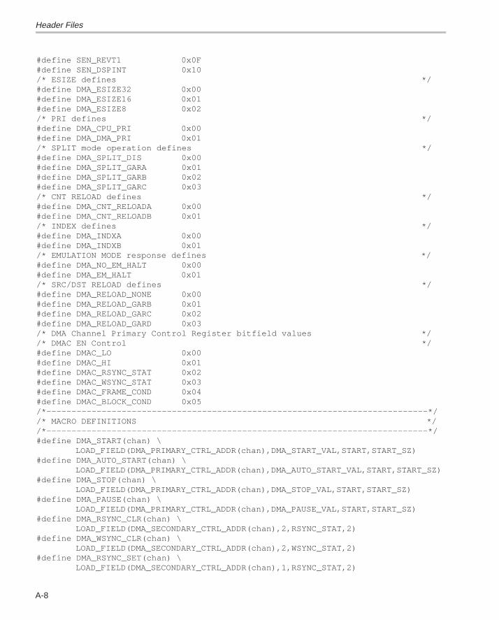
Header Files
A-8
#define SEN_REVT1 0x0F#define SEN_DSPINT 0x10/* ESIZE defines */#define DMA_ESIZE32 0x00#define DMA_ESIZE16 0x01#define DMA_ESIZE8 0x02/* PRI defines */#define DMA_CPU_PRI 0x00#define DMA_DMA_PRI 0x01/* SPLIT mode operation defines */#define DMA_SPLIT_DIS 0x00#define DMA_SPLIT_GARA 0x01#define DMA_SPLIT_GARB 0x02#define DMA_SPLIT_GARC 0x03/* CNT RELOAD defines */#define DMA_CNT_RELOADA 0x00#define DMA_CNT_RELOADB 0x01/* INDEX defines */#define DMA_INDXA 0x00#define DMA_INDXB 0x01/* EMULATION MODE response defines */#define DMA_NO_EM_HALT 0x00#define DMA_EM_HALT 0x01/* SRC/DST RELOAD defines */#define DMA_RELOAD_NONE 0x00#define DMA_RELOAD_GARB 0x01#define DMA_RELOAD_GARC 0x02#define DMA_RELOAD_GARD 0x03/* DMA Channel Primary Control Register bitfield values *//* DMAC EN Control */#define DMAC_LO 0x00#define DMAC_HI 0x01#define DMAC_RSYNC_STAT 0x02#define DMAC_WSYNC_STAT 0x03#define DMAC_FRAME_COND 0x04#define DMAC_BLOCK_COND 0x05/*––––––––––––––––––––––––––––––––––––––––––––––––––––––––––––––––––––––––––––*//* MACRO DEFINITIONS *//*––––––––––––––––––––––––––––––––––––––––––––––––––––––––––––––––––––––––––––*/#define DMA_START(chan) \ LOAD_FIELD(DMA_PRIMARY_CTRL_ADDR(chan),DMA_START_VAL,START,START_SZ)#define DMA_AUTO_START(chan) \ LOAD_FIELD(DMA_PRIMARY_CTRL_ADDR(chan),DMA_AUTO_START_VAL,START,START_SZ)#define DMA_STOP(chan) \ LOAD_FIELD(DMA_PRIMARY_CTRL_ADDR(chan),DMA_STOP_VAL,START,START_SZ)#define DMA_PAUSE(chan) \ LOAD_FIELD(DMA_PRIMARY_CTRL_ADDR(chan),DMA_PAUSE_VAL,START,START_SZ)#define DMA_RSYNC_CLR(chan) \ LOAD_FIELD(DMA_SECONDARY_CTRL_ADDR(chan),2,RSYNC_STAT,2)#define DMA_WSYNC_CLR(chan) \ LOAD_FIELD(DMA_SECONDARY_CTRL_ADDR(chan),2,WSYNC_STAT,2)#define DMA_RSYNC_SET(chan) \ LOAD_FIELD(DMA_SECONDARY_CTRL_ADDR(chan),1,RSYNC_STAT,2)
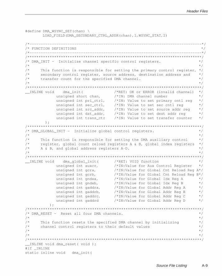
Header Files
A-9Source File Listing
#define DMA_WSYNC_SET(chan) \ LOAD_FIELD(DMA_SECONDARY_CTRL_ADDR(chan),1,WSYNC_STAT,2) /*–––––––––––––––––––––––––––––––––––––––––––––––––––––––––––––––––––––––––––––*//* FUNCTION DEFINITIONS *//*–––––––––––––––––––––––––––––––––––––––––––––––––––––––––––––––––––––––––––––*//******************************************************************************//* DMA_INIT – Initialize channel specific control registers. *//* *//* This function is responsible for setting the primary control register, *//* secondary control register, source address, destination address and *//* transfer count for the specified DMA channel. *//* *//******************************************************************************/__INLINE void dma_init( /*RET: OK or ERROR (invalid channel) */ unsigned short chan, /*IN: DMA channel number */ unsigned int pri_ctrl, /*IN: Value to set primary cntl reg */ unsigned int sec_ctrl, /*IN: Value to set sec cntl reg */ unsigned int src_addr, /*IN: Value to set source addr reg */ unsigned int dst_addr, /*IN: Value to set dest addr reg */ unsigned int trans_ctr /*IN: Value to set transfer counter */ );/******************************************************************************//* DMA_GLOBAL_INIT – Initialize global control registers. *//* *//* This function is responsible for setting the DMA auxiliary control *//* register, global count reload registers A & B, global index registers *//* A & B, and global address registers A–D. *//* *//******************************************************************************/__INLINE void dma_global_init( /*RET: VOID function */ unsigned int auxcr, /*IN:Value for Aux Control Register */ unsigned int gcra, /*IN:Value for Global Cnt Reload Reg A*/ unsigned int gcrb, /*IN:Value for Global Cnt Reload Reg B*/ unsigned int gndxa, /*IN:Value for Global Idx Reg A */ unsigned int gndxb, /*IN:Value for Global Idx Reg B */ unsigned int gaddra, /*IN:Value for Global Addr Reg A */ unsigned int gaddrb, /*IN:Value for Global Addr Reg B */ unsigned int gaddrc, /*IN:Value for Global Addr Reg C */ unsigned int gaddrd /*IN:Value for Global Addr Reg D */ );/******************************************************************************//* DMA_RESET – Reset all four DMA channels. *//* *//* This function resets the specified DMA channel by initializing *//* channel control registers to their default values *//* *//* *//******************************************************************************/__INLINE void dma_reset( void );#if _INLINEstatic inline void dma_init(
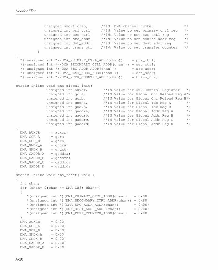
Header Files
A-10
unsigned short chan, /*IN: DMA channel number */ unsigned int pri_ctrl, /*IN: Value to set primary cntl reg */ unsigned int sec_ctrl, /*IN: Value to set sec cntl reg */ unsigned int src_addr, /*IN: Value to set source addr reg */ unsigned int dst_addr, /*IN: Value to set dest addr reg */ unsigned int trans_ctr /*IN: Value to set transfer counter */ ){ *((unsigned int *)(DMA_PRIMARY_CTRL_ADDR(chan))) = pri_ctrl; *((unsigned int *)(DMA_SECONDARY_CTRL_ADDR(chan))) = sec_ctrl; *((unsigned int *)(DMA_SRC_ADDR_ADDR(chan))) = src_addr; *((unsigned int *)(DMA_DEST_ADDR_ADDR(chan))) = dst_addr; *((unsigned int *)(DMA_XFER_COUNTER_ADDR(chan))) = trans_ctr;}static inline void dma_global_init( unsigned int auxcr, /*IN:Value for Aux Control Register */ unsigned int gcra, /*IN:Value for Global Cnt Reload Reg A*/ unsigned int gcrb, /*IN:Value for Global Cnt Reload Reg B*/ unsigned int gndxa, /*IN:Value for Global Idx Reg A */ unsigned int gndxb, /*IN:Value for Global Idx Reg B */ unsigned int gaddra, /*IN:Value for Global Addr Reg A */ unsigned int gaddrb, /*IN:Value for Global Addr Reg B */ unsigned int gaddrc, /*IN:Value for Global Addr Reg C */ unsigned int gaddrd) /*IN:Value for Global Addr Reg D */{ DMA_AUXCR = auxcr; DMA_GCR_A = gcra; DMA_GCR_B = gcrb; DMA_GNDX_A = gndxa; DMA_GNDX_B = gndxb; DMA_GADDR_A = gaddra; DMA_GADDR_B = gaddrb; DMA_GADDR_C = gaddrc; DMA_GADDR_D = gaddrd;}static inline void dma_reset( void ){ int chan; for (chan= 0;chan <= DMA_CH3; chan++) { *(unsigned int *)(DMA_PRIMARY_CTRL_ADDR(chan)) = 0x00; *(unsigned int *)(DMA_SECONDARY_CTRL_ADDR(chan)) = 0x80; *(unsigned int *)(DMA_SRC_ADDR_ADDR(chan)) = 0x00; *(unsigned int *)(DMA_DEST_ADDR_ADDR(chan)) = 0x00; *(unsigned int *)(DMA_XFER_COUNTER_ADDR(chan)) = 0x00; } DMA_AUXCR = 0x00; DMA_GCR_A = 0x00; DMA_GCR_B = 0x00; DMA_GNDX_A = 0x00; DMA_GNDX_B = 0x00; DMA_GADDR_A = 0x00; DMA_GADDR_B = 0x00;
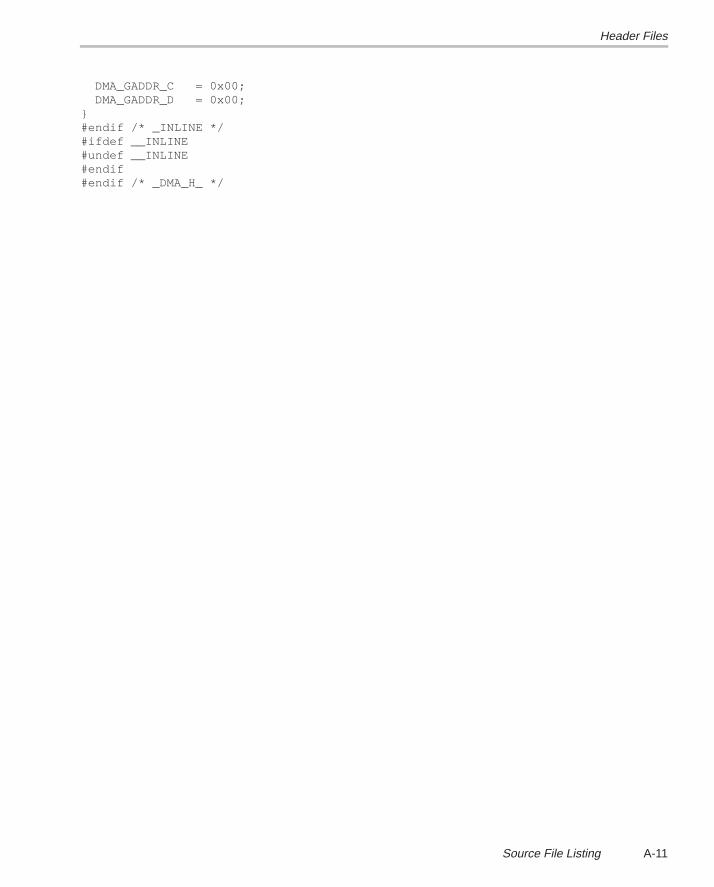
Header Files
A-11Source File Listing
DMA_GADDR_C = 0x00; DMA_GADDR_D = 0x00;}#endif /* _INLINE */#ifdef __INLINE#undef __INLINE#endif#endif /* _DMA_H_ */
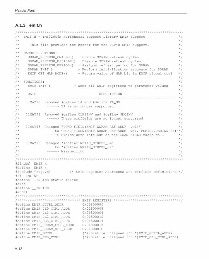
Header Files
A-12
A.1.3 emif.h
/******************************************************************************//* EMIF.H – TMS320C6x Peripheral Support Library EMIF Support *//* *//* This file provides the header for the DSP’s EMIF support. *//* *//* MACRO FUNCTIONS: *//* SDRAM_REFRESH_ENABLE() – Enable SDRAM refresh cycles *//* SDRAM_REFRESH_DISABLE() – Disable SDRAM refresh cycles *//* SDRAM_REFRESH_PERIOD() – Assigns refresh period for SDRAM *//* SDRAM_INIT() – Perform initialization sequence for SDRAM *//* EMIF_GET_MAP_MODE() – Return value of MAP bit in EMIF global ctrl *//* *//* FUNCTIONS: *//* emif_init() – Sets all EMIF registers to parameter values *//* *//* DATE DESCRIPTION *//* ––––––– ––––––––––––––––––––––––––––––––––––––––––––––––––––––––––––– *//* 11MAY98 Removed #define TA and #define TA_SZ *//* –––––> TA is no longer supported. *//* *//* 11MAY98 Removed #define CLK2INV and #define SDCINV *//* –––––> These bitfields are no longer supported. *//* *//* 11MAY98 Changed ”LOAD_FIELD(EMIF_SDRAM_REF_ADDR, val)” *//* to ”LOAD_FIELD(EMIF_SDRAM_REF_ADDR, val, PERIOD,PERIOD_SZ)”*//* –––––> Fields were left out of the LOAD_FIELD macro call *//* *//* 11MAY98 Changed ”#define WRTIE_STROBE_SZ” *//* to ”#define WRITE_STROBE_SZ” *//* –––––> Misspelling *//* *//******************************************************************************/#ifndef _EMIF_H_#define _EMIF_H_#include ”regs.h” /* EMIF Register Addresses and bitfield definitions */#if _INLINE#define __INLINE static inline#else#define __INLINE#endif/******************************************************************************//****************************** EMIF REGISTERS ********************************/#define EMIF_GCTRL_ADDR 0x01800000#define EMIF_CE0_CTRL_ADDR 0x01800008#define EMIF_CE1_CTRL_ADDR 0x01800004#define EMIF_CE2_CTRL_ADDR 0x01800010#define EMIF_CE3_CTRL_ADDR 0x01800014#define EMIF_SDRAM_CTRL_ADDR 0x01800018#define EMIF_SDRAM_REF_ADDR 0x0180001C#define EMIF_GCTRL (*(volatile unsigned int *)EMIF_GCTRL_ADDR)#define EMIF_CE0_CTRL (*(volatile unsigned int *)EMIF_CE0_CTRL_ADDR)
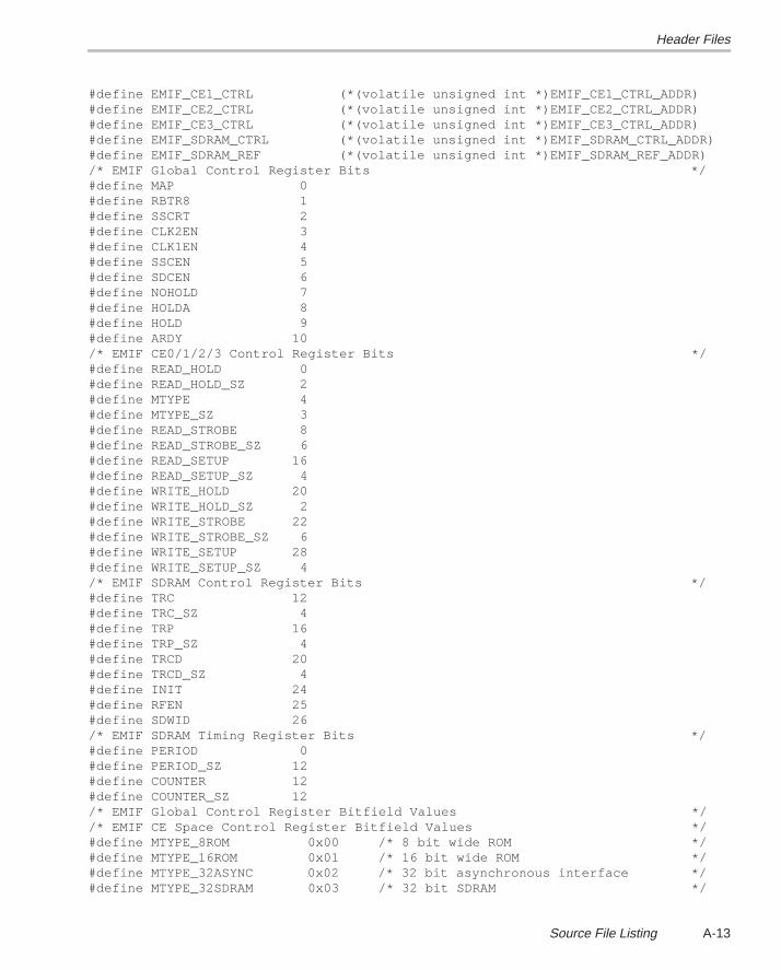
Header Files
A-13Source File Listing
#define EMIF_CE1_CTRL (*(volatile unsigned int *)EMIF_CE1_CTRL_ADDR)#define EMIF_CE2_CTRL (*(volatile unsigned int *)EMIF_CE2_CTRL_ADDR)#define EMIF_CE3_CTRL (*(volatile unsigned int *)EMIF_CE3_CTRL_ADDR)#define EMIF_SDRAM_CTRL (*(volatile unsigned int *)EMIF_SDRAM_CTRL_ADDR)#define EMIF_SDRAM_REF (*(volatile unsigned int *)EMIF_SDRAM_REF_ADDR)/* EMIF Global Control Register Bits */#define MAP 0#define RBTR8 1#define SSCRT 2#define CLK2EN 3#define CLK1EN 4#define SSCEN 5#define SDCEN 6#define NOHOLD 7#define HOLDA 8#define HOLD 9#define ARDY 10/* EMIF CE0/1/2/3 Control Register Bits */#define READ_HOLD 0#define READ_HOLD_SZ 2#define MTYPE 4#define MTYPE_SZ 3#define READ_STROBE 8#define READ_STROBE_SZ 6#define READ_SETUP 16#define READ_SETUP_SZ 4#define WRITE_HOLD 20#define WRITE_HOLD_SZ 2#define WRITE_STROBE 22#define WRITE_STROBE_SZ 6#define WRITE_SETUP 28#define WRITE_SETUP_SZ 4/* EMIF SDRAM Control Register Bits */#define TRC 12#define TRC_SZ 4#define TRP 16#define TRP_SZ 4#define TRCD 20#define TRCD_SZ 4#define INIT 24#define RFEN 25#define SDWID 26/* EMIF SDRAM Timing Register Bits */#define PERIOD 0#define PERIOD_SZ 12#define COUNTER 12#define COUNTER_SZ 12/* EMIF Global Control Register Bitfield Values *//* EMIF CE Space Control Register Bitfield Values */#define MTYPE_8ROM 0x00 /* 8 bit wide ROM */#define MTYPE_16ROM 0x01 /* 16 bit wide ROM */#define MTYPE_32ASYNC 0x02 /* 32 bit asynchronous interface */#define MTYPE_32SDRAM 0x03 /* 32 bit SDRAM */
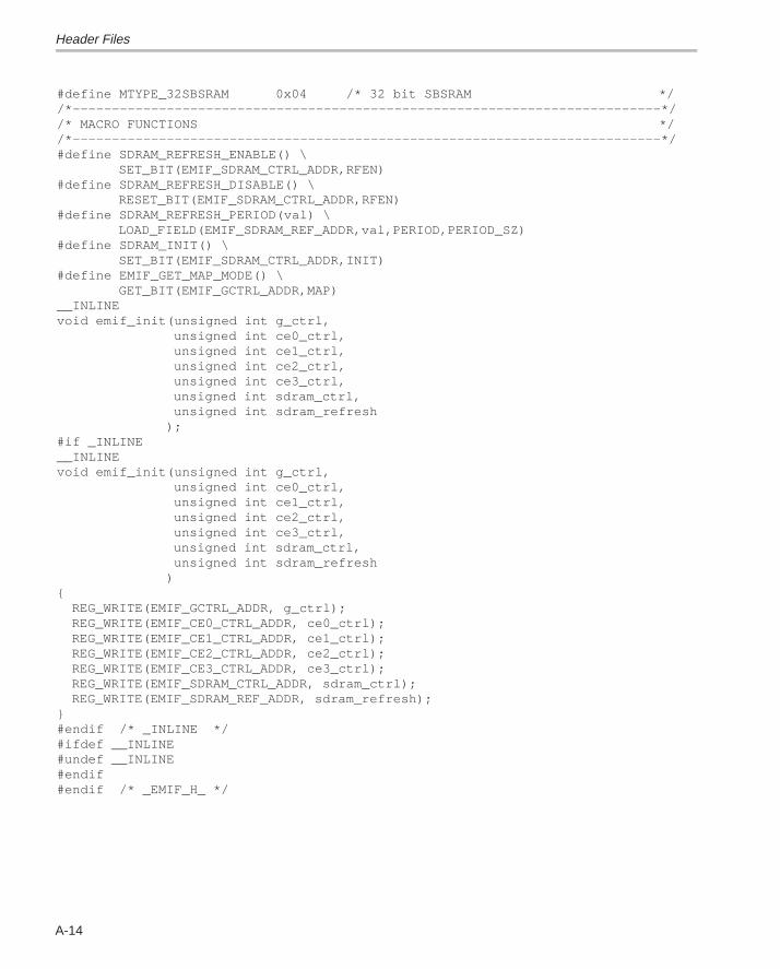
Header Files
A-14
#define MTYPE_32SBSRAM 0x04 /* 32 bit SBSRAM *//*–––––––––––––––––––––––––––––––––––––––––––––––––––––––––––––––––––––––––––*//* MACRO FUNCTIONS *//*–––––––––––––––––––––––––––––––––––––––––––––––––––––––––––––––––––––––––––*/#define SDRAM_REFRESH_ENABLE() \ SET_BIT(EMIF_SDRAM_CTRL_ADDR,RFEN)#define SDRAM_REFRESH_DISABLE() \ RESET_BIT(EMIF_SDRAM_CTRL_ADDR,RFEN)#define SDRAM_REFRESH_PERIOD(val) \ LOAD_FIELD(EMIF_SDRAM_REF_ADDR,val,PERIOD,PERIOD_SZ)#define SDRAM_INIT() \ SET_BIT(EMIF_SDRAM_CTRL_ADDR,INIT)#define EMIF_GET_MAP_MODE() \ GET_BIT(EMIF_GCTRL_ADDR,MAP)__INLINEvoid emif_init(unsigned int g_ctrl, unsigned int ce0_ctrl, unsigned int ce1_ctrl, unsigned int ce2_ctrl, unsigned int ce3_ctrl, unsigned int sdram_ctrl, unsigned int sdram_refresh );#if _INLINE__INLINEvoid emif_init(unsigned int g_ctrl, unsigned int ce0_ctrl, unsigned int ce1_ctrl, unsigned int ce2_ctrl, unsigned int ce3_ctrl, unsigned int sdram_ctrl, unsigned int sdram_refresh ){ REG_WRITE(EMIF_GCTRL_ADDR, g_ctrl); REG_WRITE(EMIF_CE0_CTRL_ADDR, ce0_ctrl); REG_WRITE(EMIF_CE1_CTRL_ADDR, ce1_ctrl); REG_WRITE(EMIF_CE2_CTRL_ADDR, ce2_ctrl); REG_WRITE(EMIF_CE3_CTRL_ADDR, ce3_ctrl); REG_WRITE(EMIF_SDRAM_CTRL_ADDR, sdram_ctrl); REG_WRITE(EMIF_SDRAM_REF_ADDR, sdram_refresh);}#endif /* _INLINE */#ifdef __INLINE#undef __INLINE#endif#endif /* _EMIF_H_ */
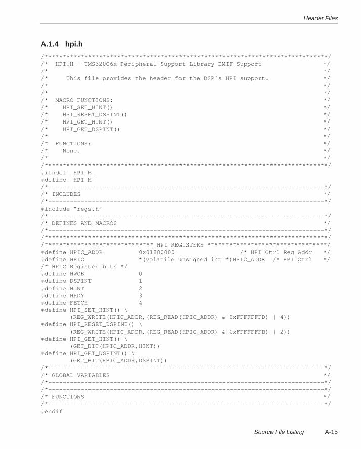
Header Files
A-15Source File Listing
A.1.4 hpi.h
/******************************************************************************//* HPI.H – TMS320C6x Peripheral Support Library EMIF Support *//* *//* This file provides the header for the DSP’s HPI support. *//* *//* *//* MACRO FUNCTIONS: *//* HPI_SET_HINT() *//* HPI_RESET_DSPINT() *//* HPI_GET_HINT() *//* HPI_GET_DSPINT() *//* *//* FUNCTIONS: *//* None. *//* *//******************************************************************************/#ifndef _HPI_H_#define _HPI_H_/*––––––––––––––––––––––––––––––––––––––––––––––––––––––––––––––––––––––––––––*//* INCLUDES *//*––––––––––––––––––––––––––––––––––––––––––––––––––––––––––––––––––––––––––––*/#include ”regs.h”/*––––––––––––––––––––––––––––––––––––––––––––––––––––––––––––––––––––––––––––*//* DEFINES AND MACROS *//*––––––––––––––––––––––––––––––––––––––––––––––––––––––––––––––––––––––––––––*//******************************************************************************//****************************** HPI REGISTERS *********************************/#define HPIC_ADDR 0x01880000 /* HPI Ctrl Reg Addr */#define HPIC *(volatile unsigned int *)HPIC_ADDR /* HPI Ctrl *//* HPIC Register bits */#define HWOB 0#define DSPINT 1#define HINT 2#define HRDY 3#define FETCH 4#define HPI_SET_HINT() \ (REG_WRITE(HPIC_ADDR,(REG_READ(HPIC_ADDR) & 0xFFFFFFFD) | 4))#define HPI_RESET_DSPINT() \ (REG_WRITE(HPIC_ADDR,(REG_READ(HPIC_ADDR) & 0xFFFFFFFB) | 2))#define HPI_GET_HINT() \ (GET_BIT(HPIC_ADDR,HINT))#define HPI_GET_DSPINT() \ (GET_BIT(HPIC_ADDR,DSPINT))/*––––––––––––––––––––––––––––––––––––––––––––––––––––––––––––––––––––––––––––*//* GLOBAL VARIABLES *//*––––––––––––––––––––––––––––––––––––––––––––––––––––––––––––––––––––––––––––*//*––––––––––––––––––––––––––––––––––––––––––––––––––––––––––––––––––––––––––––*//* FUNCTIONS *//*––––––––––––––––––––––––––––––––––––––––––––––––––––––––––––––––––––––––––––*/#endif
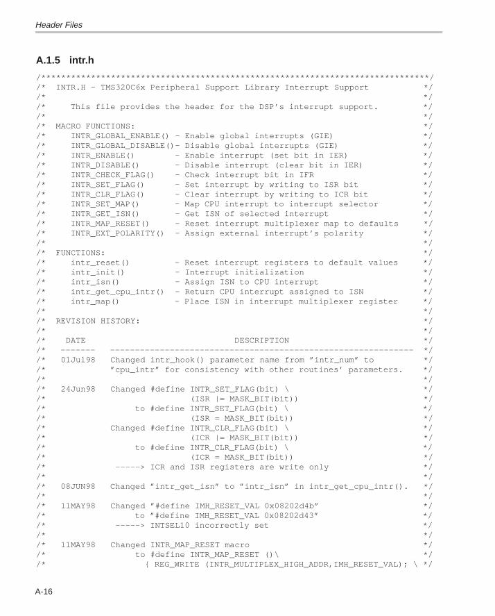
Header Files
A-16
A.1.5 intr.h
/******************************************************************************//* INTR.H – TMS320C6x Peripheral Support Library Interrupt Support *//* *//* This file provides the header for the DSP’s interrupt support. *//* *//* MACRO FUNCTIONS: *//* INTR_GLOBAL_ENABLE() – Enable global interrupts (GIE) *//* INTR_GLOBAL_DISABLE()– Disable global interrupts (GIE) *//* INTR_ENABLE() – Enable interrupt (set bit in IER) *//* INTR_DISABLE() – Disable interrupt (clear bit in IER) *//* INTR_CHECK_FLAG() – Check interrupt bit in IFR *//* INTR_SET_FLAG() – Set interrupt by writing to ISR bit *//* INTR_CLR_FLAG() – Clear interrupt by writing to ICR bit *//* INTR_SET_MAP() – Map CPU interrupt to interrupt selector *//* INTR_GET_ISN() – Get ISN of selected interrupt *//* INTR_MAP_RESET() – Reset interrupt multiplexer map to defaults *//* INTR_EXT_POLARITY() – Assign external interrupt’s polarity *//* *//* FUNCTIONS: *//* intr_reset() – Reset interrupt registers to default values *//* intr_init() – Interrupt initialization *//* intr_isn() – Assign ISN to CPU interrupt *//* intr_get_cpu_intr() – Return CPU interrupt assigned to ISN *//* intr_map() – Place ISN in interrupt multiplexer register *//* *//* REVISION HISTORY: *//* *//* DATE DESCRIPTION *//* ––––––– ––––––––––––––––––––––––––––––––––––––––––––––––––––––––––––– *//* 01Jul98 Changed intr_hook() parameter name from ”intr_num” to *//* ”cpu_intr” for consistency with other routines’ parameters. *//* *//* 24Jun98 Changed #define INTR_SET_FLAG(bit) \ *//* (ISR |= MASK_BIT(bit)) *//* to #define INTR_SET_FLAG(bit) \ *//* (ISR = MASK_BIT(bit)) *//* Changed #define INTR_CLR_FLAG(bit) \ *//* (ICR |= MASK_BIT(bit)) *//* to #define INTR_CLR_FLAG(bit) \ *//* (ICR = MASK_BIT(bit)) *//* –––––> ICR and ISR registers are write only *//* *//* 08JUN98 Changed ”intr_get_isn” to ”intr_isn” in intr_get_cpu_intr(). *//* *//* 11MAY98 Changed ”#define IMH_RESET_VAL 0x08202d4b” *//* to ”#define IMH_RESET_VAL 0x08202d43” *//* –––––> INTSEL10 incorrectly set *//* *//* 11MAY98 Changed INTR_MAP_RESET macro *//* to #define INTR_MAP_RESET ()\ *//* { REG_WRITE (INTR_MULTIPLEX_HIGH_ADDR,IMH_RESET_VAL); \ */
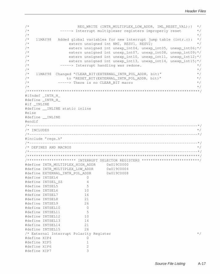
Header Files
A-17Source File Listing
/* REG_WRITE (INTR_MULTIPLEX_LOW_ADDR, IML_RESET_VAL);} *//* –––––> Interrupt multiplexer registers improperly reset *//* *//* 11MAY98 Added global variables for new interrupt jump table (intr.c): *//* extern unsigned int NMI, RESV1, RESV2; *//* extern unsigned int unexp_int04, unexp_int05, unexp_int06;*//* extern unsigned int unexp_int07, unexp_int08, unexp_int09;*//* extern unsigned int unexp_int10, unexp_int11, unexp_int12;*//* extern unsigned int unexp_int13, unexp_int14, unexp_int15;*//* –––––> Interrupt handling was redone. *//* *//* 11MAY98 Changed ”CLEAR_BIT(EXTERNAL_INTR_POL_ADDR, bit)” *//* to ”RESET_BIT(EXTERNAL_INTR_POL_ADDR, bit)” *//* –––––> There is no CLEAR_BIT macro *//* *//******************************************************************************/#ifndef _INTR_H_#define _INTR_H_#if _INLINE#define __INLINE static inline#else#define __INLINE#endif/*––––––––––––––––––––––––––––––––––––––––––––––––––––––––––––––––––––––––––––*//* INCLUDES *//*––––––––––––––––––––––––––––––––––––––––––––––––––––––––––––––––––––––––––––*/#include ”regs.h”/*––––––––––––––––––––––––––––––––––––––––––––––––––––––––––––––––––––––––––––*//* DEFINES AND MACROS *//*––––––––––––––––––––––––––––––––––––––––––––––––––––––––––––––––––––––––––––*//******************************************************************************//********************** INTERRUPT SELECTOR REGISTERS **************************/#define INTR_MULTIPLEX_HIGH_ADDR 0x019C0000#define INTR_MULTIPLEX_LOW_ADDR 0x019C0004#define EXTERNAL_INTR_POL_ADDR 0x019C0008#define INTSEL4 0#define INTSEL_SZ 4#define INTSEL5 5#define INTSEL6 10#define INTSEL7 16#define INTSEL8 21#define INTSEL9 26#define INTSEL10 0#define INTSEL11 5#define INTSEL12 10#define INTSEL13 16#define INTSEL14 21#define INTSEL15 26/* External Interrupt Polarity Register */#define XIP4 0#define XIP5 1#define XIP6 2#define XIP7 3
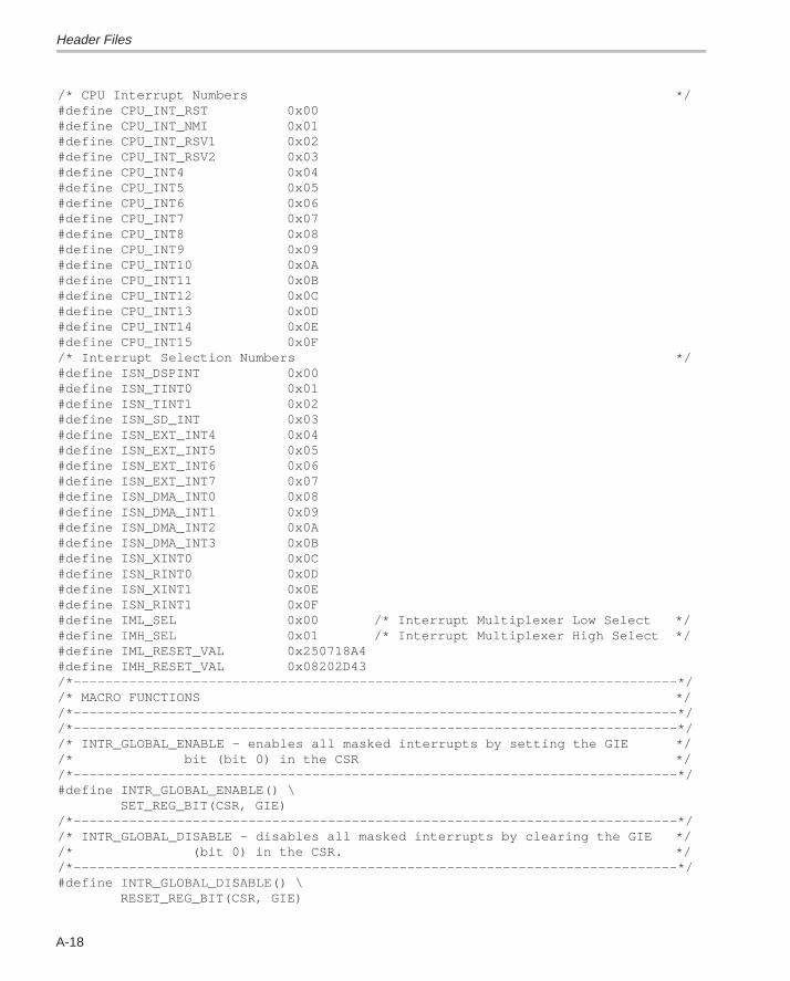
Header Files
A-18
/* CPU Interrupt Numbers */#define CPU_INT_RST 0x00#define CPU_INT_NMI 0x01#define CPU_INT_RSV1 0x02#define CPU_INT_RSV2 0x03#define CPU_INT4 0x04#define CPU_INT5 0x05#define CPU_INT6 0x06#define CPU_INT7 0x07#define CPU_INT8 0x08#define CPU_INT9 0x09#define CPU_INT10 0x0A#define CPU_INT11 0x0B#define CPU_INT12 0x0C#define CPU_INT13 0x0D#define CPU_INT14 0x0E#define CPU_INT15 0x0F/* Interrupt Selection Numbers */#define ISN_DSPINT 0x00#define ISN_TINT0 0x01#define ISN_TINT1 0x02#define ISN_SD_INT 0x03#define ISN_EXT_INT4 0x04#define ISN_EXT_INT5 0x05#define ISN_EXT_INT6 0x06#define ISN_EXT_INT7 0x07#define ISN_DMA_INT0 0x08#define ISN_DMA_INT1 0x09#define ISN_DMA_INT2 0x0A#define ISN_DMA_INT3 0x0B#define ISN_XINT0 0x0C#define ISN_RINT0 0x0D#define ISN_XINT1 0x0E#define ISN_RINT1 0x0F#define IML_SEL 0x00 /* Interrupt Multiplexer Low Select */#define IMH_SEL 0x01 /* Interrupt Multiplexer High Select */#define IML_RESET_VAL 0x250718A4#define IMH_RESET_VAL 0x08202D43/*––––––––––––––––––––––––––––––––––––––––––––––––––––––––––––––––––––––––––––*//* MACRO FUNCTIONS *//*––––––––––––––––––––––––––––––––––––––––––––––––––––––––––––––––––––––––––––*//*––––––––––––––––––––––––––––––––––––––––––––––––––––––––––––––––––––––––––––*//* INTR_GLOBAL_ENABLE – enables all masked interrupts by setting the GIE *//* bit (bit 0) in the CSR *//*––––––––––––––––––––––––––––––––––––––––––––––––––––––––––––––––––––––––––––*/#define INTR_GLOBAL_ENABLE() \ SET_REG_BIT(CSR, GIE)/*––––––––––––––––––––––––––––––––––––––––––––––––––––––––––––––––––––––––––––*//* INTR_GLOBAL_DISABLE – disables all masked interrupts by clearing the GIE *//* (bit 0) in the CSR. *//*––––––––––––––––––––––––––––––––––––––––––––––––––––––––––––––––––––––––––––*/#define INTR_GLOBAL_DISABLE() \ RESET_REG_BIT(CSR, GIE)
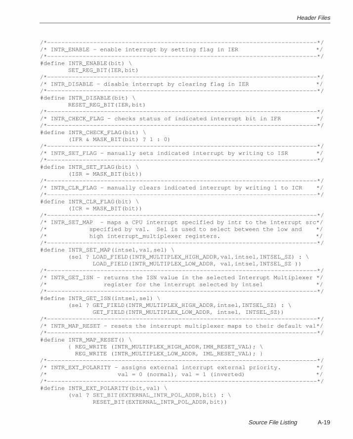
Header Files
A-19Source File Listing
/*––––––––––––––––––––––––––––––––––––––––––––––––––––––––––––––––––––––––––––*//* INTR_ENABLE – enable interrupt by setting flag in IER *//*––––––––––––––––––––––––––––––––––––––––––––––––––––––––––––––––––––––––––––*/#define INTR_ENABLE(bit) \ SET_REG_BIT(IER,bit)/*––––––––––––––––––––––––––––––––––––––––––––––––––––––––––––––––––––––––––––*//* INTR_DISABLE – disable interrupt by clearing flag in IER *//*––––––––––––––––––––––––––––––––––––––––––––––––––––––––––––––––––––––––––––*/#define INTR_DISABLE(bit) \ RESET_REG_BIT(IER,bit)/*––––––––––––––––––––––––––––––––––––––––––––––––––––––––––––––––––––––––––––*//* INTR_CHECK_FLAG – checks status of indicated interrupt bit in IFR *//*––––––––––––––––––––––––––––––––––––––––––––––––––––––––––––––––––––––––––––*/#define INTR_CHECK_FLAG(bit) \ (IFR & MASK_BIT(bit) ? 1 : 0)/*––––––––––––––––––––––––––––––––––––––––––––––––––––––––––––––––––––––––––––*//* INTR_SET_FLAG – manually sets indicated interrupt by writing to ISR *//*––––––––––––––––––––––––––––––––––––––––––––––––––––––––––––––––––––––––––––*/#define INTR_SET_FLAG(bit) \ (ISR = MASK_BIT(bit))/*––––––––––––––––––––––––––––––––––––––––––––––––––––––––––––––––––––––––––––*//* INTR_CLR_FLAG – manually clears indicated interrupt by writing 1 to ICR *//*––––––––––––––––––––––––––––––––––––––––––––––––––––––––––––––––––––––––––––*/#define INTR_CLR_FLAG(bit) \ (ICR = MASK_BIT(bit))/*––––––––––––––––––––––––––––––––––––––––––––––––––––––––––––––––––––––––––––*//* INTR_SET_MAP – maps a CPU interrupt specified by intr to the interrupt src*//* specified by val. Sel is used to select between the low and *//* high interrupt_multiplexer registers. *//*––––––––––––––––––––––––––––––––––––––––––––––––––––––––––––––––––––––––––––*/#define INTR_SET_MAP(intsel,val,sel) \ (sel ? LOAD_FIELD(INTR_MULTIPLEX_HIGH_ADDR,val,intsel,INTSEL_SZ) : \ LOAD_FIELD(INTR_MULTIPLEX_LOW_ADDR, val,intsel,INTSEL_SZ ))/*––––––––––––––––––––––––––––––––––––––––––––––––––––––––––––––––––––––––––––*//* INTR_GET_ISN – returns the ISN value in the selected Interrupt Multiplexer *//* register for the interrupt selected by intsel *//*––––––––––––––––––––––––––––––––––––––––––––––––––––––––––––––––––––––––––––*/#define INTR_GET_ISN(intsel,sel) \ (sel ? GET_FIELD(INTR_MULTIPLEX_HIGH_ADDR,intsel,INTSEL_SZ) : \ GET_FIELD(INTR_MULTIPLEX_LOW_ADDR, intsel, INTSEL_SZ))/*––––––––––––––––––––––––––––––––––––––––––––––––––––––––––––––––––––––––––––*//* INTR_MAP_RESET – resets the interrupt multiplexer maps to their default val*//*––––––––––––––––––––––––––––––––––––––––––––––––––––––––––––––––––––––––––––*/#define INTR_MAP_RESET() \ { REG_WRITE (INTR_MULTIPLEX_HIGH_ADDR,IMH_RESET_VAL); \ REG_WRITE (INTR_MULTIPLEX_LOW_ADDR, IML_RESET_VAL); }/*––––––––––––––––––––––––––––––––––––––––––––––––––––––––––––––––––––––––––––*//* INTR_EXT_POLARITY – assigns external interrupt external priority. *//* val = 0 (normal), val = 1 (inverted) *//*––––––––––––––––––––––––––––––––––––––––––––––––––––––––––––––––––––––––––––*/#define INTR_EXT_POLARITY(bit,val) \ (val ? SET_BIT(EXTERNAL_INTR_POL_ADDR,bit) : \ RESET_BIT(EXTERNAL_INTR_POL_ADDR,bit))
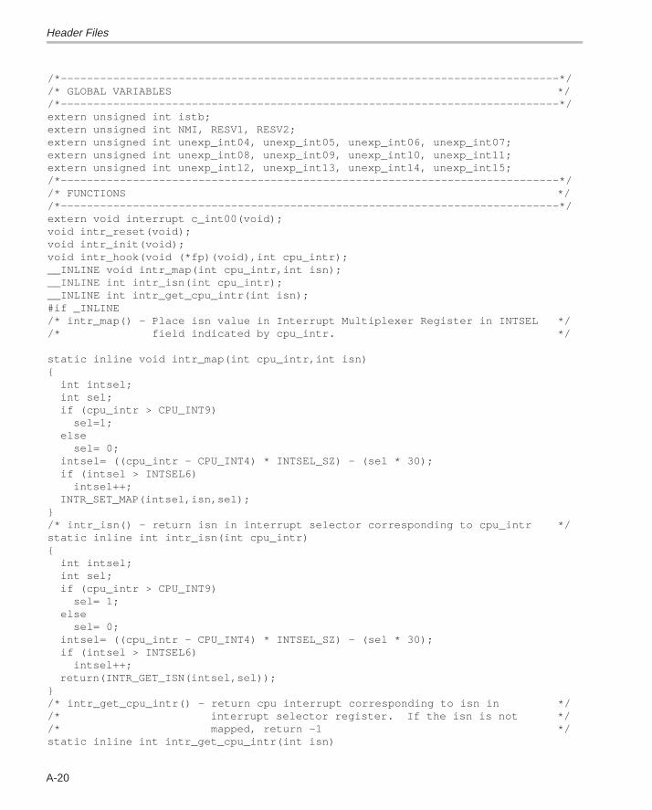
Header Files
A-20
/*––––––––––––––––––––––––––––––––––––––––––––––––––––––––––––––––––––––––––––*//* GLOBAL VARIABLES *//*––––––––––––––––––––––––––––––––––––––––––––––––––––––––––––––––––––––––––––*/extern unsigned int istb;extern unsigned int NMI, RESV1, RESV2;extern unsigned int unexp_int04, unexp_int05, unexp_int06, unexp_int07;extern unsigned int unexp_int08, unexp_int09, unexp_int10, unexp_int11;extern unsigned int unexp_int12, unexp_int13, unexp_int14, unexp_int15;/*––––––––––––––––––––––––––––––––––––––––––––––––––––––––––––––––––––––––––––*//* FUNCTIONS *//*––––––––––––––––––––––––––––––––––––––––––––––––––––––––––––––––––––––––––––*/extern void interrupt c_int00(void);void intr_reset(void);void intr_init(void);void intr_hook(void (*fp)(void),int cpu_intr);__INLINE void intr_map(int cpu_intr,int isn);__INLINE int intr_isn(int cpu_intr);__INLINE int intr_get_cpu_intr(int isn);#if _INLINE/* intr_map() – Place isn value in Interrupt Multiplexer Register in INTSEL *//* field indicated by cpu_intr. */ static inline void intr_map(int cpu_intr,int isn){ int intsel; int sel; if (cpu_intr > CPU_INT9) sel=1; else sel= 0; intsel= ((cpu_intr – CPU_INT4) * INTSEL_SZ) – (sel * 30); if (intsel > INTSEL6) intsel++; INTR_SET_MAP(intsel,isn,sel);}/* intr_isn() – return isn in interrupt selector corresponding to cpu_intr */static inline int intr_isn(int cpu_intr){ int intsel; int sel; if (cpu_intr > CPU_INT9) sel= 1; else sel= 0; intsel= ((cpu_intr – CPU_INT4) * INTSEL_SZ) – (sel * 30); if (intsel > INTSEL6) intsel++; return(INTR_GET_ISN(intsel,sel));}/* intr_get_cpu_intr() – return cpu interrupt corresponding to isn in *//* interrupt selector register. If the isn is not *//* mapped, return –1 */static inline int intr_get_cpu_intr(int isn)
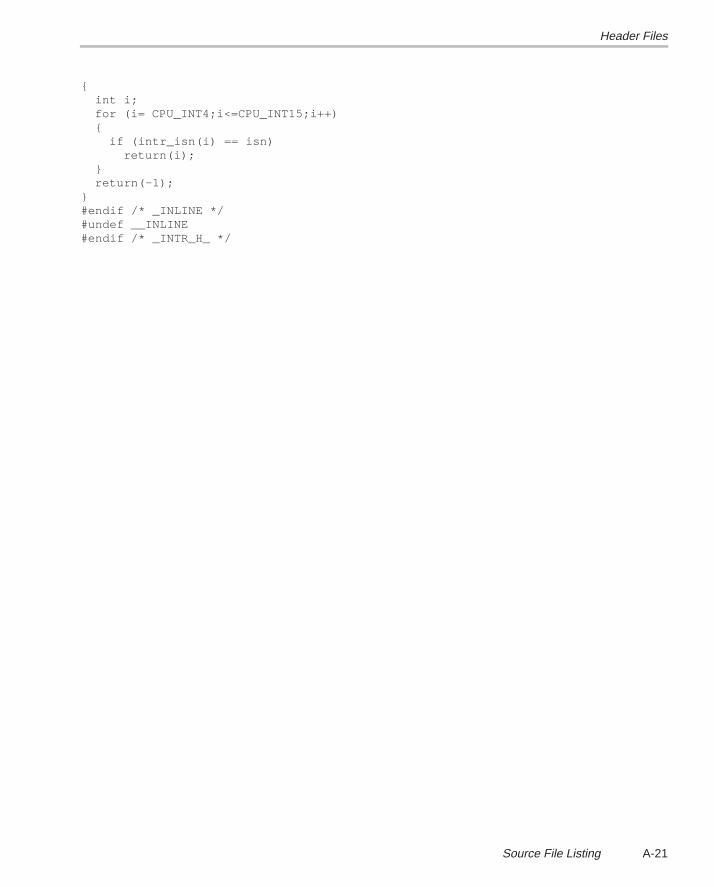
Header Files
A-21Source File Listing
{ int i; for (i= CPU_INT4;i<=CPU_INT15;i++) { if (intr_isn(i) == isn) return(i); } return(–1);}#endif /* _INLINE */#undef __INLINE#endif /* _INTR_H_ */
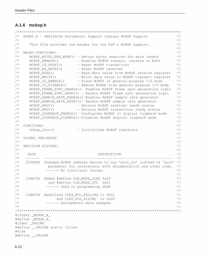
Header Files
A-22
A.1.6 mcbsp.h
/******************************************************************************//* MCBSP.H – TMS320C6x Peripheral Support Library McBSP Support *//* *//* This file provides the header for the DSP’s McBSP support. *//* *//* MACRO FUNCTIONS: *//* MCBSP_BYTES_PER_WORD() – Return bytes required for word length *//* MCBSP_ENABLE() – Enables McBSP transit, receive or both *//* MCBSP_TX_RESET() – Reset McBSP transmitter *//* MCBSP_RX_RESET() – Reset McBSP receiver *//* MCBSP_READ() – Read data value from McBSP receive register *//* MCBSP_WRITE() – Write data value to McBSP transmit register *//* MCBSP_IO_ENABLE() – Place McBSP in general–purpose I/O mode *//* MCBSP_IO_DISABLE() – Remove McBSP from general–purpose I/O mode *//* MCBSP_FRAME_SYNC_ENABLE()– Enables McBSP frame sync generation logic *//* MCBSP_FRAME_SYNC_RESET() – Resets McBSP frame sync generation logic *//* MCBSP_SAMPLE_RATE_ENABLE()–Enables McBSP sample rate generator *//* MCBSP_SAMPLE_RATE_RESET()– Resets McBSP sample rate generator *//* MCBSP_RRDY() – Returns McBSP receiver ready status *//* MCBSP_XRDY() – Returns McBSP transmitter ready status *//* MCBSP_LOOPBACK_ENABLE()– Configures McBSP in digital loopback mode *//* MCBSP_LOOPBACK_DISABLE()–Disables McBSP digital loopback mode *//* *//* FUNCTIONS: *//* mcbsp_init() – Initializes McBSP registers *//* *//* GLOBAL VARIABLES *//* *//* REVISION HISTORY: *//* *//* DATE DESCRIPTION *//* ––––––– –––––––––––––––––––––––––––––––––––––––––––––––––––––––––––––– *//* 15JUN98 Changed McBSP address macros to use ”port_no” instead of ”port” *//* parameter for consistency with documentation and other code. *//* –––––> No functional change. *//* *//* 11MAY98 Added #define CLK_MODE_CLKS 0x00 *//* and #define CLK_MODE_CPU 0x01 *//* –––––> Used in programming SRGR *//* *//* 11MAY98 Redefined CLKS_POL_FALLING to 0x01 *//* and CLKS_POL_RISING to 0x00 *//* –––––> Assignments were swapped *//* *//******************************************************************************/#ifndef _MCBSP_H_#define _MCBSP_H_#ifdef _INLINE#define __INLINE static inline#else#define __INLINE
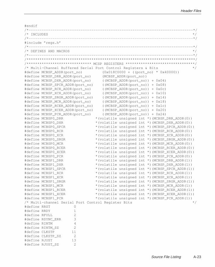
Header Files
A-23Source File Listing
#endif/*––––––––––––––––––––––––––––––––––––––––––––––––––––––––––––––––––––––––––––*//* INCLUDES *//*––––––––––––––––––––––––––––––––––––––––––––––––––––––––––––––––––––––––––––*/#include ”regs.h”/*––––––––––––––––––––––––––––––––––––––––––––––––––––––––––––––––––––––––––––*//* DEFINES AND MACROS *//*––––––––––––––––––––––––––––––––––––––––––––––––––––––––––––––––––––––––––––*//******************************************************************************//****************************** MCSP REGISTERS ********************************//* Multi–Channel Buffered Serial Port Control Registers & Bits */#define MCBSP_ADDR(port_no) (0x018C0000 + ((port_no) * 0x40000))#define MCBSP_DRR_ADDR(port_no) (MCBSP_ADDR(port_no))#define MCBSP_DXR_ADDR(port_no) ((MCBSP_ADDR(port_no)) + 0x04)#define MCBSP_SPCR_ADDR(port_no) ((MCBSP_ADDR(port_no)) + 0x08)#define MCBSP_RCR_ADDR(port_no) ((MCBSP_ADDR(port_no)) + 0x0c)#define MCBSP_XCR_ADDR(port_no) ((MCBSP_ADDR(port_no)) + 0x10)#define MCBSP_SRGR_ADDR(port_no) ((MCBSP_ADDR(port_no)) + 0x14)#define MCBSP_MCR_ADDR(port_no) ((MCBSP_ADDR(port_no)) + 0x18)#define MCBSP_RCER_ADDR(port_no) ((MCBSP_ADDR(port_no)) + 0x1c)#define MCBSP_XCER_ADDR(port_no) ((MCBSP_ADDR(port_no)) + 0x20)#define MCBSP_PCR_ADDR(port_no) ((MCBSP_ADDR(port_no)) + 0x24)#define MCBSP0_DRR *(volatile unsigned int *)(MCBSP_DRR_ADDR(0))#define MCBSP0_DXR *(volatile unsigned int *)(MCBSP_DXR_ADDR(0))#define MCBSP0_SPCR *(volatile unsigned int *)(MCBSP_SPCR_ADDR(0))#define MCBSP0_RCR *(volatile unsigned int *)(MCBSP_RCR_ADDR(0))#define MCBSP0_XCR *(volatile unsigned int *)(MCBSP_XCR_ADDR(0))#define MCBSP0_SRGR *(volatile unsigned int *)(MCBSP_SRGR_ADDR(0))#define MCBSP0_MCR *(volatile unsigned int *)(MCBSP_MCR_ADDR(0))#define MCBSP0_RCER *(volatile unsigned int *)(MCBSP_RCER_ADDR(0))#define MCBSP0_XCER *(volatile unsigned int *)(MCBSP_XCER_ADDR(0))#define MCBSP0_PCR *(volatile unsigned int *)(MCBSP_PCR_ADDR(0))#define MCBSP1_DRR *(volatile unsigned int *)(MCBSP_DRR_ADDR(1))#define MCBSP1_DXR *(volatile unsigned int *)(MCBSP_DXR_ADDR(1))#define MCBSP1_SPCR *(volatile unsigned int *)(MCBSP_SPCR_ADDR(1))#define MCBSP1_RCR *(volatile unsigned int *)(MCBSP_RCR_ADDR(1))#define MCBSP1_XCR *(volatile unsigned int *)(MCBSP_XCR_ADDR(1))#define MCBSP1_SRGR *(volatile unsigned int *)(MCBSP_SRGR_ADDR(1))#define MCBSP1_MCR *(volatile unsigned int *)(MCBSP_MCR_ADDR(1))#define MCBSP1_RCER *(volatile unsigned int *)(MCBSP_RCER_ADDR(1))#define MCBSP1_XCER *(volatile unsigned int *)(MCBSP_XCER_ADDR(1))#define MCBSP1_PCR *(volatile unsigned int *)(MCBSP_PCR_ADDR(1))/* Multi–channel Serial Port Control Register Bits */#define RRST 0#define RRDY 1#define RFULL 2#define RSYNC_ERR 3#define RINTM 4#define RINTM_SZ 2#define CLKSTP 11#define CLKSTP_SZ 2#define RJUST 13#define RJUST_SZ 2
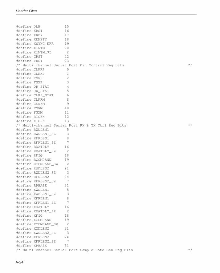
Header Files
A-24
#define DLB 15#define XRST 16#define XRDY 17#define XEMPTY 18#define XSYNC_ERR 19#define XINTM 20#define XINTM_SZ 2#define GRST 22#define FRST 23/* Multi–channel Serial Port Pin Control Reg Bits */#define CLKRP 0#define CLKXP 1#define FSRP 2#define FSXP 3#define DR_STAT 4#define DX_STAT 5#define CLKS_STAT 6#define CLKRM 8#define CLKXM 9#define FSRM 10#define FSXM 11#define RIOEN 12#define XIOEN 13/* Multi–channel Serial Port RX & TX Ctrl Reg Bits */#define RWDLEN1 5#define RWDLEN1_SZ 3#define RFRLEN1 8#define RFRLEN1_SZ 7#define RDATDLY 16#define RDATDLY_SZ 2#define RFIG 18#define RCOMPAND 19#define RCOMPAND_SZ 2#define RWDLEN2 21#define RWDLEN2_SZ 3#define RFRLEN2 24#define RFRLEN2_SZ 7#define RPHASE 31#define XWDLEN1 5#define XWDLEN1_SZ 3#define XFRLEN1 8#define XFRLEN1_SZ 7#define XDATDLY 16#define XDATDLY_SZ 2#define XFIG 18#define XCOMPAND 19#define XCOMPAND_SZ 2#define XWDLEN2 21#define XWDLEN2_SZ 3#define XFRLEN2 24#define XFRLEN2_SZ 7#define XPHASE 31/* Multi–channel Serial Port Sample Rate Gen Reg Bits */
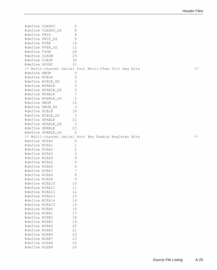
Header Files
A-25Source File Listing
#define CLKGDV 0#define CLKGDV_SZ 8#define FWID 8#define FWID_SZ 8#define FPER 16#define FPER_SZ 12#define FSGM 28#define CLKSM 29#define CLKSP 30#define GSYNC 31/* Multi–channel Serial Port Multi–Chan Ctrl Reg Bits */#define RMCM 0#define RCBLK 2#define RCBLK_SZ 3#define RPABLK 5#define RPABLK_SZ 2#define RPBBLK 7#define RPBBLK_SZ 2#define XMCM 16#define XMCM_SZ 2#define XCBLK 18#define XCBLK_SZ 3#define XPABLK 21#define XPABLK_SZ 2#define XPBBLK 23#define XPBBLK_SZ 2/* Multi–channel Serial Port Rec Enable Register Bits */#define RCEA0 0#define RCEA1 1#define RCEA2 2#define RCEA3 3#define RCEA4 4#define RCEA5 5#define RCEA6 6#define RCEA7 7#define RCEA8 8#define RCEA9 9#define RCEA10 10#define RCEA11 11#define RCEA12 12#define RCEA13 13#define RCEA14 14#define RCEA15 15#define RCEB0 16#define RCEB1 17#define RCEB2 18#define RCEB3 19#define RCEB4 20#define RCEB5 21#define RCEB6 22#define RCEB7 23#define RCEB8 24#define RCEB9 25
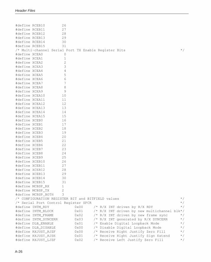
Header Files
A-26
#define RCEB10 26#define RCEB11 27#define RCEB12 28#define RCEB13 29#define RCEB14 30#define RCEB15 31/* Multi–channel Serial Port TX Enable Register Bits */#define XCEA0 0#define XCEA1 1#define XCEA2 2#define XCEA3 3#define XCEA4 4#define XCEA5 5#define XCEA6 6#define XCEA7 7#define XCEA8 8#define XCEA9 9#define XCEA10 10#define XCEA11 11#define XCEA12 12#define XCEA13 13#define XCEA14 14#define XCEA15 15#define XCEB0 16#define XCEB1 17#define XCEB2 18#define XCEB3 19#define XCEB4 20#define XCEB5 21#define XCEB6 22#define XCEB7 23#define XCEB8 24#define XCEB9 25#define XCEB10 26#define XCEB11 27#define XCEB12 28#define XCEB13 29#define XCEB14 30#define XCEB15 31#define MCBSP_RX 1#define MCBSP_TX 2#define MCBSP_BOTH 3/* CONFIGURATION REGISTER BIT and BITFIELD values *//* Serial Port Control Register SPCR */#define INTM_RDY 0x00 /* R/X INT driven by R/X RDY */#define INTM_BLOCK 0x01 /* R/X INT driven by new multichannel blk*/#define INTM_FRAME 0x02 /* R/X INT driven by new frame sync */#define INTM_SYNCERR 0x03 /* R/X INT generated by R/X SYNCERR */#define DLB_ENABLE 0x01 /* Enable Digital Loopback Mode */#define DLB_DISABLE 0x00 /* Disable Digital Loopback Mode */#define RXJUST_RJZF 0x00 /* Receive Right Justify Zero Fill */#define RXJUST_RJSE 0x01 /* Receive Right Justify Sign Extend */#define RXJUST_LJZF 0x02 /* Receive Left Justify Zero Fill */
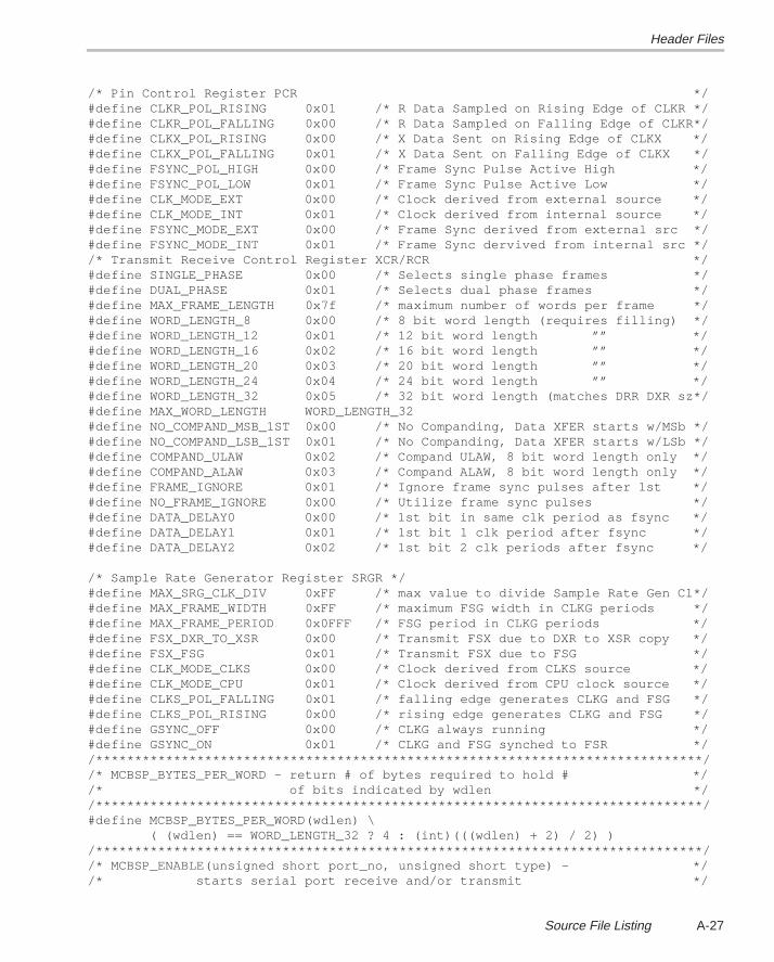
Header Files
A-27Source File Listing
/* Pin Control Register PCR */#define CLKR_POL_RISING 0x01 /* R Data Sampled on Rising Edge of CLKR */#define CLKR_POL_FALLING 0x00 /* R Data Sampled on Falling Edge of CLKR*/#define CLKX_POL_RISING 0x00 /* X Data Sent on Rising Edge of CLKX */#define CLKX_POL_FALLING 0x01 /* X Data Sent on Falling Edge of CLKX */#define FSYNC_POL_HIGH 0x00 /* Frame Sync Pulse Active High */#define FSYNC_POL_LOW 0x01 /* Frame Sync Pulse Active Low */#define CLK_MODE_EXT 0x00 /* Clock derived from external source */#define CLK_MODE_INT 0x01 /* Clock derived from internal source */#define FSYNC_MODE_EXT 0x00 /* Frame Sync derived from external src */#define FSYNC_MODE_INT 0x01 /* Frame Sync dervived from internal src *//* Transmit Receive Control Register XCR/RCR */#define SINGLE_PHASE 0x00 /* Selects single phase frames */#define DUAL_PHASE 0x01 /* Selects dual phase frames */#define MAX_FRAME_LENGTH 0x7f /* maximum number of words per frame */#define WORD_LENGTH_8 0x00 /* 8 bit word length (requires filling) */#define WORD_LENGTH_12 0x01 /* 12 bit word length ”” */#define WORD_LENGTH_16 0x02 /* 16 bit word length ”” */#define WORD_LENGTH_20 0x03 /* 20 bit word length ”” */#define WORD_LENGTH_24 0x04 /* 24 bit word length ”” */#define WORD_LENGTH_32 0x05 /* 32 bit word length (matches DRR DXR sz*/#define MAX_WORD_LENGTH WORD_LENGTH_32#define NO_COMPAND_MSB_1ST 0x00 /* No Companding, Data XFER starts w/MSb */#define NO_COMPAND_LSB_1ST 0x01 /* No Companding, Data XFER starts w/LSb */#define COMPAND_ULAW 0x02 /* Compand ULAW, 8 bit word length only */#define COMPAND_ALAW 0x03 /* Compand ALAW, 8 bit word length only */#define FRAME_IGNORE 0x01 /* Ignore frame sync pulses after 1st */#define NO_FRAME_IGNORE 0x00 /* Utilize frame sync pulses */#define DATA_DELAY0 0x00 /* 1st bit in same clk period as fsync */#define DATA_DELAY1 0x01 /* 1st bit 1 clk period after fsync */#define DATA_DELAY2 0x02 /* 1st bit 2 clk periods after fsync */ /* Sample Rate Generator Register SRGR */#define MAX_SRG_CLK_DIV 0xFF /* max value to divide Sample Rate Gen Cl*/#define MAX_FRAME_WIDTH 0xFF /* maximum FSG width in CLKG periods */#define MAX_FRAME_PERIOD 0x0FFF /* FSG period in CLKG periods */#define FSX_DXR_TO_XSR 0x00 /* Transmit FSX due to DXR to XSR copy */#define FSX_FSG 0x01 /* Transmit FSX due to FSG */#define CLK_MODE_CLKS 0x00 /* Clock derived from CLKS source */#define CLK_MODE_CPU 0x01 /* Clock derived from CPU clock source */#define CLKS_POL_FALLING 0x01 /* falling edge generates CLKG and FSG */#define CLKS_POL_RISING 0x00 /* rising edge generates CLKG and FSG */#define GSYNC_OFF 0x00 /* CLKG always running */#define GSYNC_ON 0x01 /* CLKG and FSG synched to FSR *//******************************************************************************//* MCBSP_BYTES_PER_WORD – return # of bytes required to hold # *//* of bits indicated by wdlen *//******************************************************************************/#define MCBSP_BYTES_PER_WORD(wdlen) \ ( (wdlen) == WORD_LENGTH_32 ? 4 : (int)(((wdlen) + 2) / 2) )/******************************************************************************//* MCBSP_ENABLE(unsigned short port_no, unsigned short type) – *//* starts serial port receive and/or transmit */
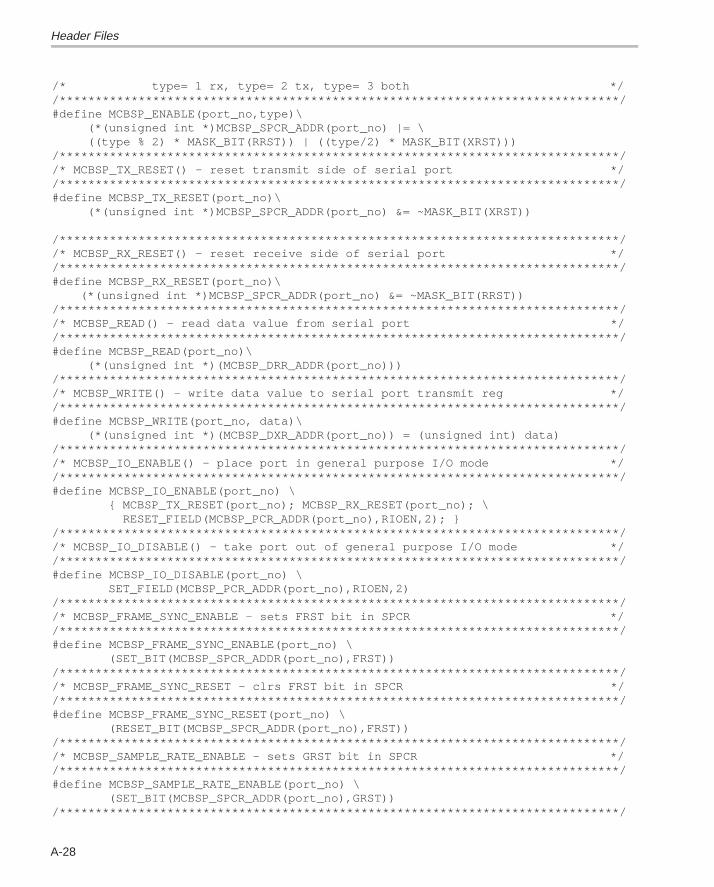
Header Files
A-28
/* type= 1 rx, type= 2 tx, type= 3 both *//******************************************************************************/#define MCBSP_ENABLE(port_no,type)\ (*(unsigned int *)MCBSP_SPCR_ADDR(port_no) |= \ ((type % 2) * MASK_BIT(RRST)) | ((type/2) * MASK_BIT(XRST)))/******************************************************************************//* MCBSP_TX_RESET() – reset transmit side of serial port *//******************************************************************************/#define MCBSP_TX_RESET(port_no)\ (*(unsigned int *)MCBSP_SPCR_ADDR(port_no) &= ~MASK_BIT(XRST)) /******************************************************************************//* MCBSP_RX_RESET() – reset receive side of serial port *//******************************************************************************/#define MCBSP_RX_RESET(port_no)\ (*(unsigned int *)MCBSP_SPCR_ADDR(port_no) &= ~MASK_BIT(RRST))/******************************************************************************//* MCBSP_READ() – read data value from serial port *//******************************************************************************/#define MCBSP_READ(port_no)\ (*(unsigned int *)(MCBSP_DRR_ADDR(port_no)))/******************************************************************************//* MCBSP_WRITE() – write data value to serial port transmit reg *//******************************************************************************/#define MCBSP_WRITE(port_no, data)\ (*(unsigned int *)(MCBSP_DXR_ADDR(port_no)) = (unsigned int) data)/******************************************************************************//* MCBSP_IO_ENABLE() – place port in general purpose I/O mode *//******************************************************************************/#define MCBSP_IO_ENABLE(port_no) \ { MCBSP_TX_RESET(port_no); MCBSP_RX_RESET(port_no); \ RESET_FIELD(MCBSP_PCR_ADDR(port_no),RIOEN,2); }/******************************************************************************//* MCBSP_IO_DISABLE() – take port out of general purpose I/O mode *//******************************************************************************/#define MCBSP_IO_DISABLE(port_no) \ SET_FIELD(MCBSP_PCR_ADDR(port_no),RIOEN,2)/******************************************************************************//* MCBSP_FRAME_SYNC_ENABLE – sets FRST bit in SPCR *//******************************************************************************/#define MCBSP_FRAME_SYNC_ENABLE(port_no) \ (SET_BIT(MCBSP_SPCR_ADDR(port_no),FRST))/******************************************************************************//* MCBSP_FRAME_SYNC_RESET – clrs FRST bit in SPCR *//******************************************************************************/#define MCBSP_FRAME_SYNC_RESET(port_no) \ (RESET_BIT(MCBSP_SPCR_ADDR(port_no),FRST))/******************************************************************************//* MCBSP_SAMPLE_RATE_ENABLE – sets GRST bit in SPCR *//******************************************************************************/#define MCBSP_SAMPLE_RATE_ENABLE(port_no) \ (SET_BIT(MCBSP_SPCR_ADDR(port_no),GRST))/******************************************************************************/
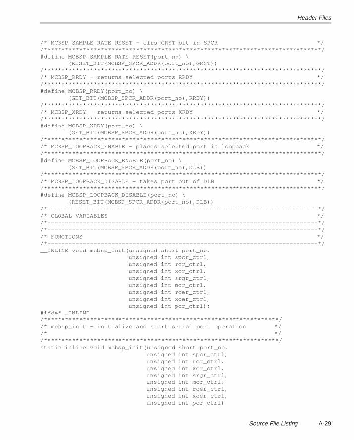
Header Files
A-29Source File Listing
/* MCBSP_SAMPLE_RATE_RESET – clrs GRST bit in SPCR *//******************************************************************************/#define MCBSP_SAMPLE_RATE_RESET(port_no) \ (RESET_BIT(MCBSP_SPCR_ADDR(port_no),GRST))/******************************************************************************//* MCBSP_RRDY – returns selected ports RRDY *//******************************************************************************/#define MCBSP_RRDY(port_no) \ (GET_BIT(MCBSP_SPCR_ADDR(port_no),RRDY))/******************************************************************************//* MCBSP_XRDY – returns selected ports XRDY *//******************************************************************************/#define MCBSP_XRDY(port_no) \ (GET_BIT(MCBSP_SPCR_ADDR(port_no),XRDY))/******************************************************************************//* MCBSP_LOOPBACK_ENABLE – places selected port in loopback *//******************************************************************************/#define MCBSP_LOOPBACK_ENABLE(port_no) \ (SET_BIT(MCBSP_SPCR_ADDR(port_no),DLB))/******************************************************************************//* MCBSP_LOOPBACK_DISABLE – takes port out of DLB *//******************************************************************************/#define MCBSP_LOOPBACK_DISABLE(port_no) \ (RESET_BIT(MCBSP_SPCR_ADDR(port_no),DLB))/*––––––––––––––––––––––––––––––––––––––––––––––––––––––––––––––––––––––––––––*//* GLOBAL VARIABLES *//*––––––––––––––––––––––––––––––––––––––––––––––––––––––––––––––––––––––––––––*//*––––––––––––––––––––––––––––––––––––––––––––––––––––––––––––––––––––––––––––*//* FUNCTIONS *//*––––––––––––––––––––––––––––––––––––––––––––––––––––––––––––––––––––––––––––*/__INLINE void mcbsp_init(unsigned short port_no, unsigned int spcr_ctrl, unsigned int rcr_ctrl, unsigned int xcr_ctrl, unsigned int srgr_ctrl, unsigned int mcr_ctrl, unsigned int rcer_ctrl, unsigned int xcer_ctrl, unsigned int pcr_ctrl);#ifdef _INLINE/******************************************************************//* mcbsp_init – initialize and start serial port operation *//* *//******************************************************************/static inline void mcbsp_init(unsigned short port_no, unsigned int spcr_ctrl, unsigned int rcr_ctrl, unsigned int xcr_ctrl, unsigned int srgr_ctrl, unsigned int mcr_ctrl, unsigned int rcer_ctrl, unsigned int xcer_ctrl, unsigned int pcr_ctrl)
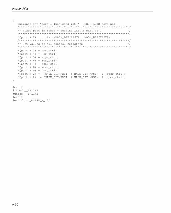
Header Files
A-30
{ unsigned int *port = (unsigned int *)(MCBSP_ADDR(port_no)); /****************************************************************/ /* Place port in reset – setting XRST & RRST to 0 */ /****************************************************************/ *(port + 2) &= ~(MASK_BIT(RRST) | MASK_BIT(XRST)); /****************************************************************/ /* Set values of all control reigsters */ /****************************************************************/ *(port + 3) = rcr_ctrl; *(port + 4) = xcr_ctrl; *(port + 5) = srgr_ctrl; *(port + 6) = mcr_ctrl; *(port + 7) = rcer_ctrl; *(port + 8) = xcer_ctrl; *(port + 9) = pcr_ctrl; *(port + 2) = ~(MASK_BIT(RRST) | MASK_BIT(XRST)) & (spcr_ctrl); *(port + 2) |= (MASK_BIT(RRST) | MASK_BIT(XRST)) & (spcr_ctrl);} #endif#ifdef __INLINE#undef __INLINE#endif#endif /* _MCBSP_H_ */
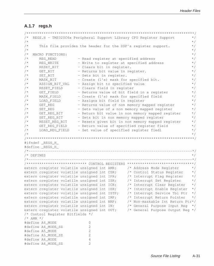
Header Files
A-31Source File Listing
A.1.7 regs.h
/******************************************************************************//* REGS.H – TMS320C6x Peripheral Support Library CPU Register Support *//* *//* This file provides the header for the DSP’s register support. *//* *//* MACRO FUNCTIONS: *//* REG_READ – Read register at specified address *//* REG_WRITE – Write to register at specified address *//* RESET_BIT – Clears bit in register. *//* GET_BIT – Returns bit value in register. *//* SET_BIT – Sets bit in register. *//* MASK_BIT – Create (1’s) mask for specified bit. *//* ASSIGN_BIT_VAL – Assign bit to specified value *//* RESET_FIELD – Clears field in register *//* GET_FIELD – Returns value of bit field in a register *//* MASK_FIELD – Create (1’s) mask for specified field *//* LOAD_FIELD – Assigns bit field in register *//* GET_REG – Returns value of non memory mapped register *//* SET_REG – Sets value of a non memory mapped register *//* GET_REG_BIT – Return bit value in non memory mapped register *//* SET_REG_BIT – Sets bit in non memory mapped register *//* RESET_REG_BIT – Resets given bit in non memory mapped register *//* GET_REG_FIELD – Return value of specified register field *//* LOAD_REG_FIELD – Set value of specified register fiedl *//* *//******************************************************************************/#ifndef _REGS_H_#define _REGS_H_/*––––––––––––––––––––––––––––––––––––––––––––––––––––––––––––––––––––––––––––*//* DEFINES *//*––––––––––––––––––––––––––––––––––––––––––––––––––––––––––––––––––––––––––––*//**************************** CONTROL REGISTERS *******************************/extern cregister volatile unsigned int AMR; /* Address Mode Register */extern cregister volatile unsigned int CSR; /* Control Status Register */extern cregister volatile unsigned int IFR; /* Interrupt Flag Register */extern cregister volatile unsigned int ISR; /* Interrupt Set Register */extern cregister volatile unsigned int ICR; /* Interrupt Clear Register */extern cregister volatile unsigned int IER; /* Interrupt Enable Register */extern cregister volatile unsigned int ISTP; /* Interrupt Service Tbl Ptr */extern cregister volatile unsigned int IRP; /* Interrupt Return Pointer */extern cregister volatile unsigned int NRP; /* Non–maskable Int Return Ptr*/extern cregister volatile unsigned int IN; /* General Purpose Input Reg */extern cregister volatile unsigned int OUT; /* General Purpose Output Reg *//* Control Register Bitfields *//* AMR */#define A4_MODE 0#define A4_MODE_SZ 2#define A5_MODE 2#define A5_MODE_SZ 2#define A6_MODE 4#define A6_MODE_SZ 2
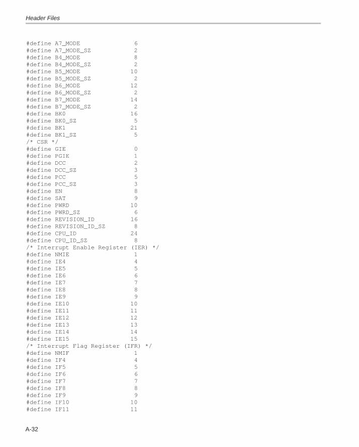
Header Files
A-32
#define A7_MODE 6#define A7_MODE_SZ 2#define B4_MODE 8#define B4_MODE_SZ 2#define B5_MODE 10#define B5_MODE_SZ 2#define B6_MODE 12#define B6_MODE_SZ 2#define B7_MODE 14#define B7_MODE_SZ 2#define BK0 16#define BK0_SZ 5#define BK1 21#define BK1_SZ 5/* CSR */#define GIE 0#define PGIE 1#define DCC 2#define DCC_SZ 3#define PCC 5#define PCC_SZ 3#define EN 8#define SAT 9#define PWRD 10#define PWRD_SZ 6#define REVISION_ID 16#define REVISION_ID_SZ 8#define CPU_ID 24#define CPU_ID_SZ 8/* Interrupt Enable Register (IER) */#define NMIE 1#define IE4 4#define IE5 5#define IE6 6#define IE7 7#define IE8 8#define IE9 9#define IE10 10#define IE11 11#define IE12 12#define IE13 13#define IE14 14#define IE15 15/* Interrupt Flag Register (IFR) */#define NMIF 1#define IF4 4#define IF5 5#define IF6 6#define IF7 7#define IF8 8#define IF9 9#define IF10 10#define IF11 11
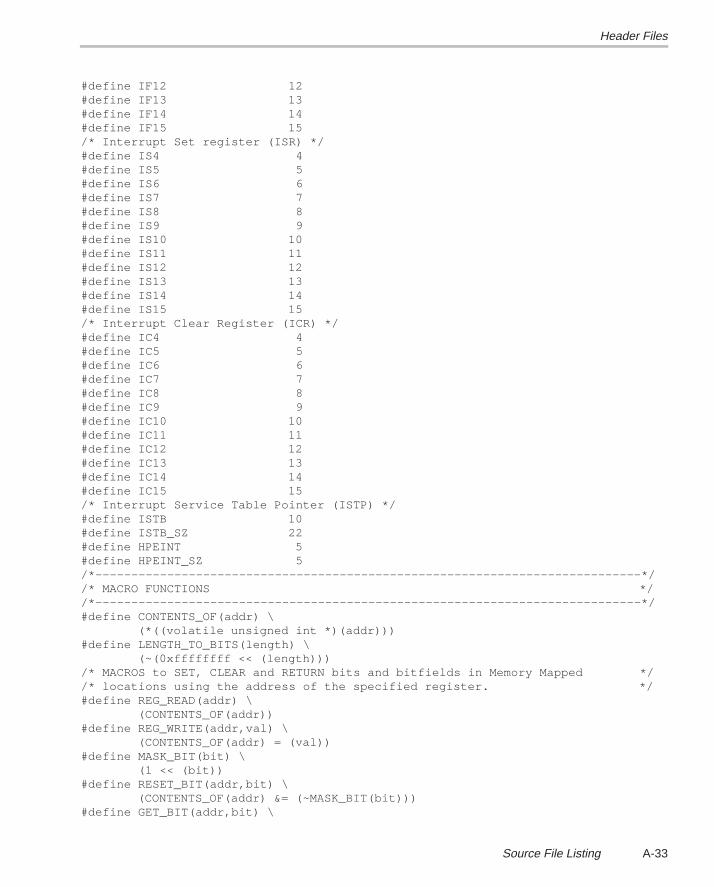
Header Files
A-33Source File Listing
#define IF12 12#define IF13 13#define IF14 14#define IF15 15/* Interrupt Set register (ISR) */#define IS4 4#define IS5 5#define IS6 6#define IS7 7#define IS8 8#define IS9 9#define IS10 10#define IS11 11#define IS12 12#define IS13 13#define IS14 14#define IS15 15/* Interrupt Clear Register (ICR) */#define IC4 4#define IC5 5#define IC6 6#define IC7 7#define IC8 8#define IC9 9#define IC10 10#define IC11 11#define IC12 12#define IC13 13#define IC14 14#define IC15 15/* Interrupt Service Table Pointer (ISTP) */#define ISTB 10#define ISTB_SZ 22#define HPEINT 5#define HPEINT_SZ 5/*––––––––––––––––––––––––––––––––––––––––––––––––––––––––––––––––––––––––––––*//* MACRO FUNCTIONS *//*––––––––––––––––––––––––––––––––––––––––––––––––––––––––––––––––––––––––––––*/#define CONTENTS_OF(addr) \ (*((volatile unsigned int *)(addr)))#define LENGTH_TO_BITS(length) \ (~(0xffffffff << (length)))/* MACROS to SET, CLEAR and RETURN bits and bitfields in Memory Mapped *//* locations using the address of the specified register. */#define REG_READ(addr) \ (CONTENTS_OF(addr))#define REG_WRITE(addr,val) \ (CONTENTS_OF(addr) = (val))#define MASK_BIT(bit) \ (1 << (bit))#define RESET_BIT(addr,bit) \ (CONTENTS_OF(addr) &= (~MASK_BIT(bit)))#define GET_BIT(addr,bit) \
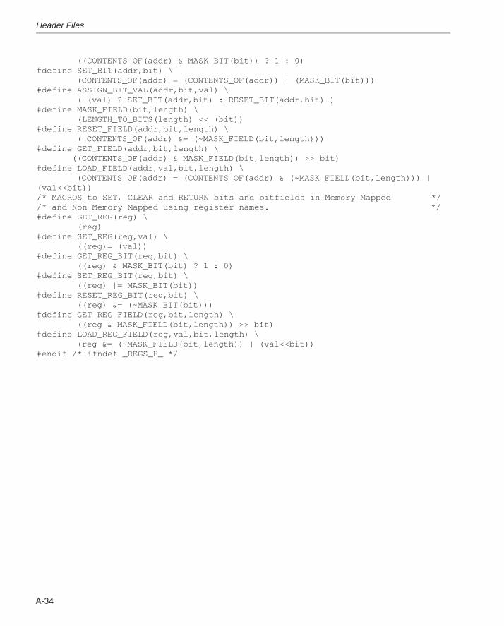
Header Files
A-34
((CONTENTS_OF(addr) & MASK_BIT(bit)) ? 1 : 0)#define SET_BIT(addr,bit) \ (CONTENTS_OF(addr) = (CONTENTS_OF(addr)) | (MASK_BIT(bit)))#define ASSIGN_BIT_VAL(addr,bit,val) \ ( (val) ? SET_BIT(addr,bit) : RESET_BIT(addr,bit) )#define MASK_FIELD(bit,length) \ (LENGTH_TO_BITS(length) << (bit))#define RESET_FIELD(addr,bit,length) \ ( CONTENTS_OF(addr) &= (~MASK_FIELD(bit,length)))#define GET_FIELD(addr,bit,length) \ ((CONTENTS_OF(addr) & MASK_FIELD(bit,length)) >> bit)#define LOAD_FIELD(addr,val,bit,length) \ (CONTENTS_OF(addr) = (CONTENTS_OF(addr) & (~MASK_FIELD(bit,length))) |(val<<bit))/* MACROS to SET, CLEAR and RETURN bits and bitfields in Memory Mapped *//* and Non–Memory Mapped using register names. */#define GET_REG(reg) \ (reg)#define SET_REG(reg,val) \ ((reg)= (val))#define GET_REG_BIT(reg,bit) \ ((reg) & MASK_BIT(bit) ? 1 : 0)#define SET_REG_BIT(reg,bit) \ ((reg) |= MASK_BIT(bit))#define RESET_REG_BIT(reg,bit) \ ((reg) &= (~MASK_BIT(bit)))#define GET_REG_FIELD(reg,bit,length) \ ((reg & MASK_FIELD(bit,length)) >> bit)#define LOAD_REG_FIELD(reg,val,bit,length) \ (reg &= (~MASK_FIELD(bit,length)) | (val<<bit))#endif /* ifndef _REGS_H_ */
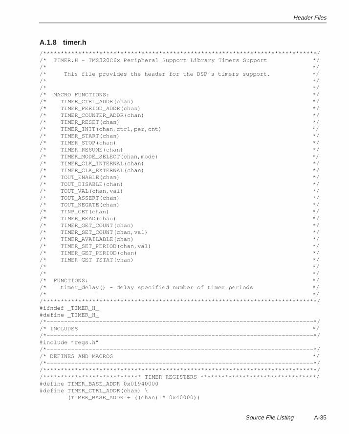
Header Files
A-35Source File Listing
A.1.8 timer.h/******************************************************************************//* TIMER.H – TMS320C6x Peripheral Support Library Timers Support *//* *//* This file provides the header for the DSP’s timers support. *//* *//* *//* MACRO FUNCTIONS: *//* TIMER_CTRL_ADDR(chan) *//* TIMER_PERIOD_ADDR(chan) *//* TIMER_COUNTER_ADDR(chan) *//* TIMER_RESET(chan) *//* TIMER_INIT(chan,ctrl,per,cnt) *//* TIMER_START(chan) *//* TIMER_STOP(chan) *//* TIMER_RESUME(chan) *//* TIMER_MODE_SELECT(chan,mode) *//* TIMER_CLK_INTERNAL(chan) *//* TIMER_CLK_EXTERNAL(chan) *//* TOUT_ENABLE(chan) *//* TOUT_DISABLE(chan) *//* TOUT_VAL(chan,val) *//* TOUT_ASSERT(chan) *//* TOUT_NEGATE(chan) *//* TINP_GET(chan) *//* TIMER_READ(chan) *//* TIMER_GET_COUNT(chan) *//* TIMER_SET_COUNT(chan,val) *//* TIMER_AVAILABLE(chan) *//* TIMER_SET_PERIOD(chan,val) *//* TIMER_GET_PERIOD(chan) *//* TIMER_GET_TSTAT(chan) *//* *//* *//* FUNCTIONS: *//* timer_delay() – delay specified number of timer periods *//* *//******************************************************************************/#ifndef _TIMER_H_#define _TIMER_H_/*––––––––––––––––––––––––––––––––––––––––––––––––––––––––––––––––––––––––––––*//* INCLUDES *//*––––––––––––––––––––––––––––––––––––––––––––––––––––––––––––––––––––––––––––*/#include ”regs.h”/*––––––––––––––––––––––––––––––––––––––––––––––––––––––––––––––––––––––––––––*//* DEFINES AND MACROS *//*––––––––––––––––––––––––––––––––––––––––––––––––––––––––––––––––––––––––––––*//******************************************************************************//**************************** TIMER REGISTERS *********************************/#define TIMER_BASE_ADDR 0x01940000#define TIMER_CTRL_ADDR(chan) \ (TIMER_BASE_ADDR + ((chan) * 0x40000))
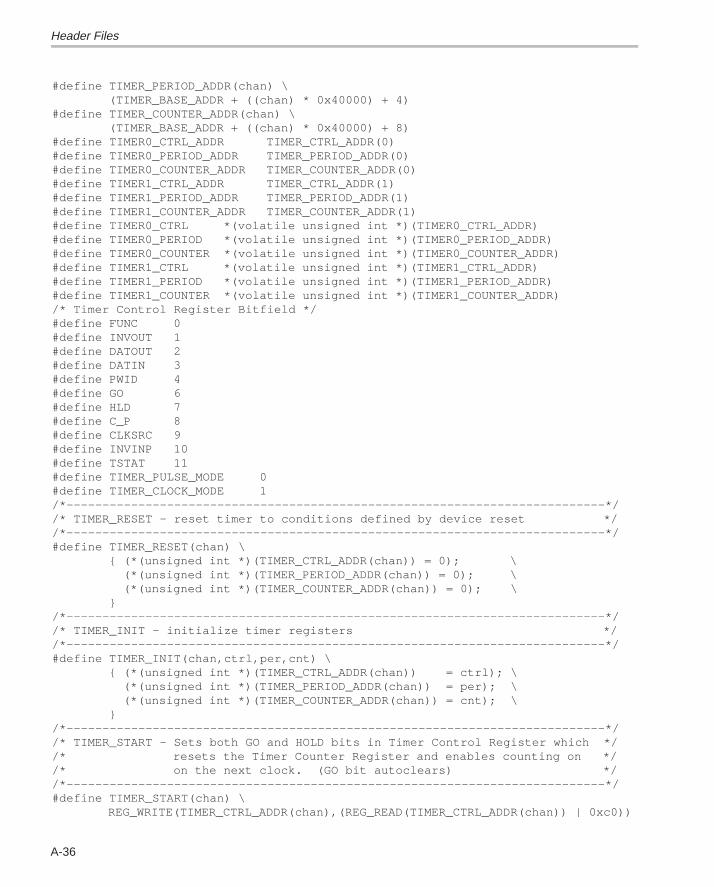
Header Files
A-36
#define TIMER_PERIOD_ADDR(chan) \ (TIMER_BASE_ADDR + ((chan) * 0x40000) + 4)#define TIMER_COUNTER_ADDR(chan) \ (TIMER_BASE_ADDR + ((chan) * 0x40000) + 8)#define TIMER0_CTRL_ADDR TIMER_CTRL_ADDR(0)#define TIMER0_PERIOD_ADDR TIMER_PERIOD_ADDR(0)#define TIMER0_COUNTER_ADDR TIMER_COUNTER_ADDR(0)#define TIMER1_CTRL_ADDR TIMER_CTRL_ADDR(1)#define TIMER1_PERIOD_ADDR TIMER_PERIOD_ADDR(1)#define TIMER1_COUNTER_ADDR TIMER_COUNTER_ADDR(1)#define TIMER0_CTRL *(volatile unsigned int *)(TIMER0_CTRL_ADDR)#define TIMER0_PERIOD *(volatile unsigned int *)(TIMER0_PERIOD_ADDR)#define TIMER0_COUNTER *(volatile unsigned int *)(TIMER0_COUNTER_ADDR)#define TIMER1_CTRL *(volatile unsigned int *)(TIMER1_CTRL_ADDR)#define TIMER1_PERIOD *(volatile unsigned int *)(TIMER1_PERIOD_ADDR)#define TIMER1_COUNTER *(volatile unsigned int *)(TIMER1_COUNTER_ADDR)/* Timer Control Register Bitfield */#define FUNC 0#define INVOUT 1#define DATOUT 2#define DATIN 3#define PWID 4#define GO 6#define HLD 7#define C_P 8#define CLKSRC 9#define INVINP 10#define TSTAT 11#define TIMER_PULSE_MODE 0#define TIMER_CLOCK_MODE 1/*–––––––––––––––––––––––––––––––––––––––––––––––––––––––––––––––––––––––––––*//* TIMER_RESET – reset timer to conditions defined by device reset *//*–––––––––––––––––––––––––––––––––––––––––––––––––––––––––––––––––––––––––––*/#define TIMER_RESET(chan) \ { (*(unsigned int *)(TIMER_CTRL_ADDR(chan)) = 0); \ (*(unsigned int *)(TIMER_PERIOD_ADDR(chan)) = 0); \ (*(unsigned int *)(TIMER_COUNTER_ADDR(chan)) = 0); \ }/*–––––––––––––––––––––––––––––––––––––––––––––––––––––––––––––––––––––––––––*//* TIMER_INIT – initialize timer registers *//*–––––––––––––––––––––––––––––––––––––––––––––––––––––––––––––––––––––––––––*/#define TIMER_INIT(chan,ctrl,per,cnt) \ { (*(unsigned int *)(TIMER_CTRL_ADDR(chan)) = ctrl); \ (*(unsigned int *)(TIMER_PERIOD_ADDR(chan)) = per); \ (*(unsigned int *)(TIMER_COUNTER_ADDR(chan)) = cnt); \ }/*–––––––––––––––––––––––––––––––––––––––––––––––––––––––––––––––––––––––––––*//* TIMER_START – Sets both GO and HOLD bits in Timer Control Register which *//* resets the Timer Counter Register and enables counting on *//* on the next clock. (GO bit autoclears) *//*–––––––––––––––––––––––––––––––––––––––––––––––––––––––––––––––––––––––––––*/#define TIMER_START(chan) \ REG_WRITE(TIMER_CTRL_ADDR(chan),(REG_READ(TIMER_CTRL_ADDR(chan)) | 0xc0))
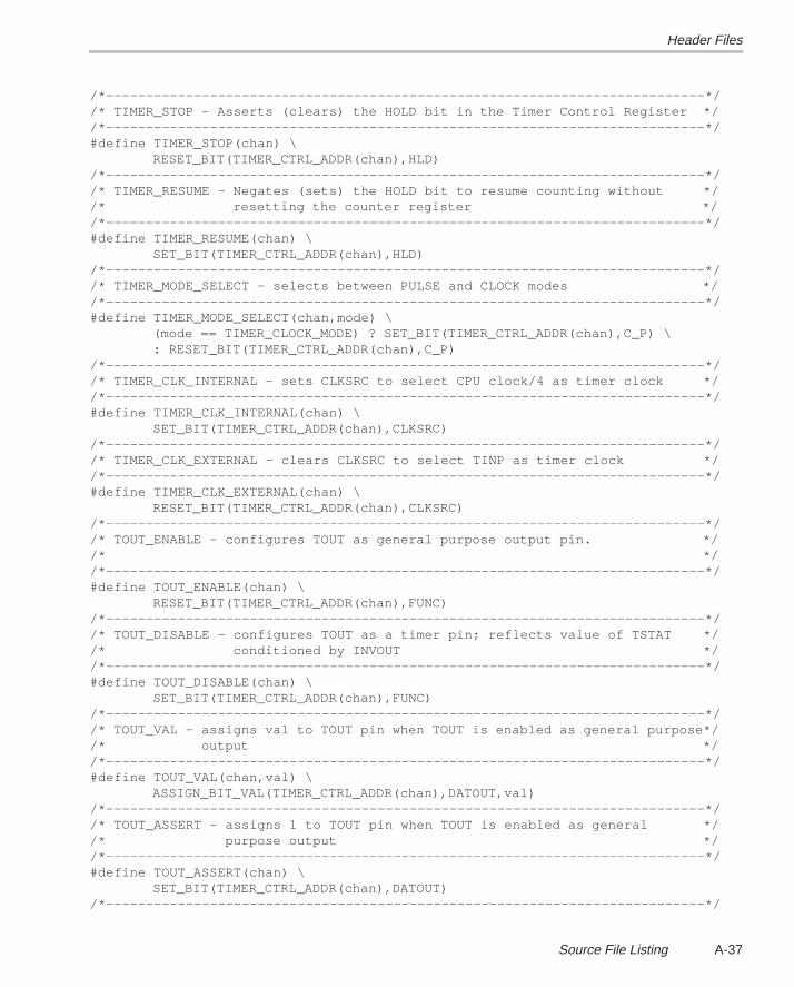
Header Files
A-37Source File Listing
/*–––––––––––––––––––––––––––––––––––––––––––––––––––––––––––––––––––––––––––*//* TIMER_STOP – Asserts (clears) the HOLD bit in the Timer Control Register *//*–––––––––––––––––––––––––––––––––––––––––––––––––––––––––––––––––––––––––––*/#define TIMER_STOP(chan) \ RESET_BIT(TIMER_CTRL_ADDR(chan),HLD)/*–––––––––––––––––––––––––––––––––––––––––––––––––––––––––––––––––––––––––––*//* TIMER_RESUME – Negates (sets) the HOLD bit to resume counting without *//* resetting the counter register *//*–––––––––––––––––––––––––––––––––––––––––––––––––––––––––––––––––––––––––––*/#define TIMER_RESUME(chan) \ SET_BIT(TIMER_CTRL_ADDR(chan),HLD)/*–––––––––––––––––––––––––––––––––––––––––––––––––––––––––––––––––––––––––––*//* TIMER_MODE_SELECT – selects between PULSE and CLOCK modes *//*–––––––––––––––––––––––––––––––––––––––––––––––––––––––––––––––––––––––––––*/#define TIMER_MODE_SELECT(chan,mode) \ (mode == TIMER_CLOCK_MODE) ? SET_BIT(TIMER_CTRL_ADDR(chan),C_P) \ : RESET_BIT(TIMER_CTRL_ADDR(chan),C_P)/*–––––––––––––––––––––––––––––––––––––––––––––––––––––––––––––––––––––––––––*//* TIMER_CLK_INTERNAL – sets CLKSRC to select CPU clock/4 as timer clock *//*–––––––––––––––––––––––––––––––––––––––––––––––––––––––––––––––––––––––––––*/#define TIMER_CLK_INTERNAL(chan) \ SET_BIT(TIMER_CTRL_ADDR(chan),CLKSRC)/*–––––––––––––––––––––––––––––––––––––––––––––––––––––––––––––––––––––––––––*//* TIMER_CLK_EXTERNAL – clears CLKSRC to select TINP as timer clock *//*–––––––––––––––––––––––––––––––––––––––––––––––––––––––––––––––––––––––––––*/#define TIMER_CLK_EXTERNAL(chan) \ RESET_BIT(TIMER_CTRL_ADDR(chan),CLKSRC)/*–––––––––––––––––––––––––––––––––––––––––––––––––––––––––––––––––––––––––––*//* TOUT_ENABLE – configures TOUT as general purpose output pin. *//* *//*–––––––––––––––––––––––––––––––––––––––––––––––––––––––––––––––––––––––––––*/#define TOUT_ENABLE(chan) \ RESET_BIT(TIMER_CTRL_ADDR(chan),FUNC)/*–––––––––––––––––––––––––––––––––––––––––––––––––––––––––––––––––––––––––––*//* TOUT_DISABLE – configures TOUT as a timer pin; reflects value of TSTAT *//* conditioned by INVOUT *//*–––––––––––––––––––––––––––––––––––––––––––––––––––––––––––––––––––––––––––*/#define TOUT_DISABLE(chan) \ SET_BIT(TIMER_CTRL_ADDR(chan),FUNC)/*–––––––––––––––––––––––––––––––––––––––––––––––––––––––––––––––––––––––––––*//* TOUT_VAL – assigns val to TOUT pin when TOUT is enabled as general purpose*//* output *//*–––––––––––––––––––––––––––––––––––––––––––––––––––––––––––––––––––––––––––*/#define TOUT_VAL(chan,val) \ ASSIGN_BIT_VAL(TIMER_CTRL_ADDR(chan),DATOUT,val)/*–––––––––––––––––––––––––––––––––––––––––––––––––––––––––––––––––––––––––––*//* TOUT_ASSERT – assigns 1 to TOUT pin when TOUT is enabled as general *//* purpose output *//*–––––––––––––––––––––––––––––––––––––––––––––––––––––––––––––––––––––––––––*/#define TOUT_ASSERT(chan) \ SET_BIT(TIMER_CTRL_ADDR(chan),DATOUT)/*–––––––––––––––––––––––––––––––––––––––––––––––––––––––––––––––––––––––––––*/
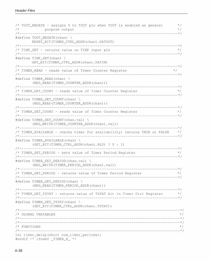
Header Files
A-38
/* TOUT_NEGATE – assigns 0 to TOUT pin when TOUT is enabled as general *//* purpose output *//*–––––––––––––––––––––––––––––––––––––––––––––––––––––––––––––––––––––––––––*/#define TOUT_NEGATE(chan) \ RESET_BIT(TIMER_CTRL_ADDR(chan),DATOUT)/*–––––––––––––––––––––––––––––––––––––––––––––––––––––––––––––––––––––––––––*//* TINP_GET – returns value on TINP input pin *//*–––––––––––––––––––––––––––––––––––––––––––––––––––––––––––––––––––––––––––*/#define TINP_GET(chan) \ GET_BIT(TIMER_CTRL_ADDR(chan),DATIN)/*–––––––––––––––––––––––––––––––––––––––––––––––––––––––––––––––––––––––––––*//* TIMER_READ – reads value of Timer Counter Register *//*–––––––––––––––––––––––––––––––––––––––––––––––––––––––––––––––––––––––––––*/#define TIMER_READ(chan) \ (REG_READ(TIMER_COUNTER_ADDR(chan)))/*–––––––––––––––––––––––––––––––––––––––––––––––––––––––––––––––––––––––––––*//* TIMER_GET_COUNT – reads value of Timer Counter Register *//*–––––––––––––––––––––––––––––––––––––––––––––––––––––––––––––––––––––––––––*/#define TIMER_GET_COUNT(chan) \ (REG_READ(TIMER_COUNTER_ADDR(chan)))/*–––––––––––––––––––––––––––––––––––––––––––––––––––––––––––––––––––––––––––*//* TIMER_SET_COUNT – reads value of Timer Counter Register *//*–––––––––––––––––––––––––––––––––––––––––––––––––––––––––––––––––––––––––––*/#define TIMER_SET_COUNT(chan,val) \ (REG_WRITE(TIMER_COUNTER_ADDR(chan),val))/*–––––––––––––––––––––––––––––––––––––––––––––––––––––––––––––––––––––––––––*//* TIMER_AVAILABLE – checks timer for availability; returns TRUE or FALSE *//*–––––––––––––––––––––––––––––––––––––––––––––––––––––––––––––––––––––––––––*/#define TIMER_AVAILABLE(chan) \ (GET_BIT(TIMER_CTRL_ADDR(chan),HLD) ? 0 : 1)/*–––––––––––––––––––––––––––––––––––––––––––––––––––––––––––––––––––––––––––*//* TIMER_SET_PERIOD – sets value of Timer Period Register *//*–––––––––––––––––––––––––––––––––––––––––––––––––––––––––––––––––––––––––––*/#define TIMER_SET_PERIOD(chan,val) \ (REG_WRITE(TIMER_PERIOD_ADDR(chan),val))/*–––––––––––––––––––––––––––––––––––––––––––––––––––––––––––––––––––––––––––*//* TIMER_GET_PERIOD – returns value of Timer Period Register *//*–––––––––––––––––––––––––––––––––––––––––––––––––––––––––––––––––––––––––––*/#define TIMER_GET_PERIOD(chan) \ (REG_READ(TIMER_PERIOD_ADDR(chan)))/*–––––––––––––––––––––––––––––––––––––––––––––––––––––––––––––––––––––––––––*//* TIMER_GET_TSTAT – returns value of TSTAT bit in Timer Ctrl Register *//*–––––––––––––––––––––––––––––––––––––––––––––––––––––––––––––––––––––––––––*/#define TIMER_GET_TSTAT(chan) \ (GET_BIT(TIMER_CTRL_ADDR(chan),TSTAT))/*––––––––––––––––––––––––––––––––––––––––––––––––––––––––––––––––––––––––––––*//* GLOBAL VARIABLES *//*––––––––––––––––––––––––––––––––––––––––––––––––––––––––––––––––––––––––––––*//*––––––––––––––––––––––––––––––––––––––––––––––––––––––––––––––––––––––––––––*//* FUNCTIONS *//*––––––––––––––––––––––––––––––––––––––––––––––––––––––––––––––––––––––––––––*/int timer_delay(short num_timer_periods);#endif /* ifndef _TIMER_H_ */
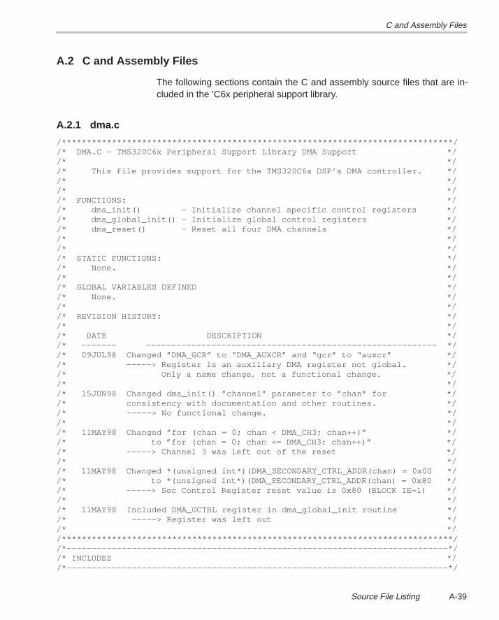
C and Assembly Files
A-39Source File Listing
A.2 C and Assembly Files
The following sections contain the C and assembly source files that are in-cluded in the ’C6x peripheral support library.
A.2.1 dma.c
/******************************************************************************//* DMA.C – TMS320C6x Peripheral Support Library DMA Support *//* *//* This file provides support for the TMS320C6x DSP’s DMA controller. *//* *//* *//* FUNCTIONS: *//* dma_init() – Initialize channel specific control registers *//* dma_global_init() – Initialize global control registers *//* dma_reset() – Reset all four DMA channels *//* *//* *//* STATIC FUNCTIONS: *//* None. *//* *//* GLOBAL VARIABLES DEFINED *//* None. *//* *//* REVISION HISTORY: *//* *//* DATE DESCRIPTION *//* ––––––– –––––––––––––––––––––––––––––––––––––––––––––––––––––––––– *//* 09JUL98 Changed ”DMA_GCR” to “DMA_AUXCR” and “gcr” to “auxcr” *//* –––––> Register is an auxiliary DMA register not global. *//* Only a name change, not a functional change. *//* *//* 15JUN98 Changed dma_init() ”channel” parameter to ”chan” for *//* consistency with documentation and other routines. *//* –––––> No functional change. *//* *//* 11MAY98 Changed ”for (chan = 0; chan < DMA_CH3; chan++)” *//* to ”for (chan = 0; chan <= DMA_CH3; chan++)” *//* –––––> Channel 3 was left out of the reset *//* *//* 11MAY98 Changed *(unsigned int*)(DMA_SECONDARY_CTRL_ADDR(chan) = 0x00 *//* to *(unsigned int*)(DMA_SECONDARY_CTRL_ADDR(chan) = 0x80 *//* –––––> Sec Control Register reset value is 0x80 (BLOCK IE=1) *//* *//* 11MAY98 Included DMA_GCTRL register in dma_global_init routine *//* –––––> Register was left out *//* *//******************************************************************************//*––––––––––––––––––––––––––––––––––––––––––––––––––––––––––––––––––––––––––––*//* INCLUDES *//*––––––––––––––––––––––––––––––––––––––––––––––––––––––––––––––––––––––––––––*/
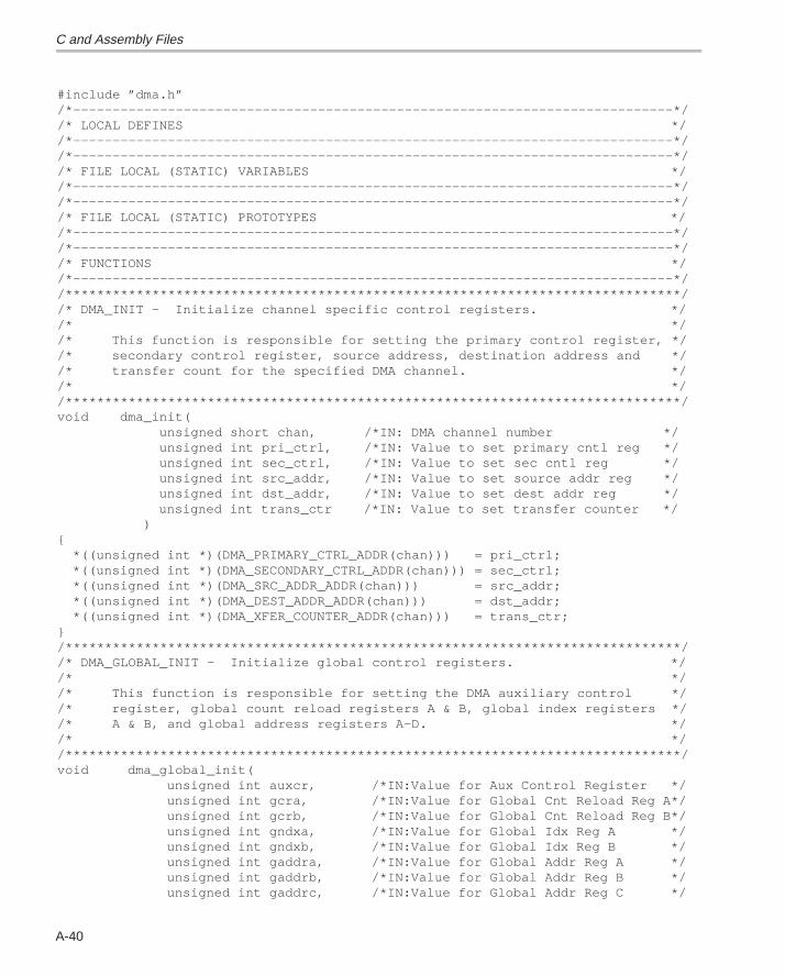
C and Assembly Files
A-40
#include ”dma.h”/*––––––––––––––––––––––––––––––––––––––––––––––––––––––––––––––––––––––––––––*//* LOCAL DEFINES *//*––––––––––––––––––––––––––––––––––––––––––––––––––––––––––––––––––––––––––––*//*––––––––––––––––––––––––––––––––––––––––––––––––––––––––––––––––––––––––––––*//* FILE LOCAL (STATIC) VARIABLES *//*––––––––––––––––––––––––––––––––––––––––––––––––––––––––––––––––––––––––––––*//*––––––––––––––––––––––––––––––––––––––––––––––––––––––––––––––––––––––––––––*//* FILE LOCAL (STATIC) PROTOTYPES *//*––––––––––––––––––––––––––––––––––––––––––––––––––––––––––––––––––––––––––––*//*––––––––––––––––––––––––––––––––––––––––––––––––––––––––––––––––––––––––––––*//* FUNCTIONS *//*––––––––––––––––––––––––––––––––––––––––––––––––––––––––––––––––––––––––––––*//******************************************************************************//* DMA_INIT – Initialize channel specific control registers. *//* *//* This function is responsible for setting the primary control register, *//* secondary control register, source address, destination address and *//* transfer count for the specified DMA channel. *//* *//******************************************************************************/void dma_init( unsigned short chan, /*IN: DMA channel number */ unsigned int pri_ctrl, /*IN: Value to set primary cntl reg */ unsigned int sec_ctrl, /*IN: Value to set sec cntl reg */ unsigned int src_addr, /*IN: Value to set source addr reg */ unsigned int dst_addr, /*IN: Value to set dest addr reg */ unsigned int trans_ctr /*IN: Value to set transfer counter */ ){ *((unsigned int *)(DMA_PRIMARY_CTRL_ADDR(chan))) = pri_ctrl; *((unsigned int *)(DMA_SECONDARY_CTRL_ADDR(chan))) = sec_ctrl; *((unsigned int *)(DMA_SRC_ADDR_ADDR(chan))) = src_addr; *((unsigned int *)(DMA_DEST_ADDR_ADDR(chan))) = dst_addr; *((unsigned int *)(DMA_XFER_COUNTER_ADDR(chan))) = trans_ctr;}/******************************************************************************//* DMA_GLOBAL_INIT – Initialize global control registers. *//* *//* This function is responsible for setting the DMA auxiliary control *//* register, global count reload registers A & B, global index registers *//* A & B, and global address registers A–D. *//* *//******************************************************************************/void dma_global_init( unsigned int auxcr, /*IN:Value for Aux Control Register */ unsigned int gcra, /*IN:Value for Global Cnt Reload Reg A*/ unsigned int gcrb, /*IN:Value for Global Cnt Reload Reg B*/ unsigned int gndxa, /*IN:Value for Global Idx Reg A */ unsigned int gndxb, /*IN:Value for Global Idx Reg B */ unsigned int gaddra, /*IN:Value for Global Addr Reg A */ unsigned int gaddrb, /*IN:Value for Global Addr Reg B */ unsigned int gaddrc, /*IN:Value for Global Addr Reg C */
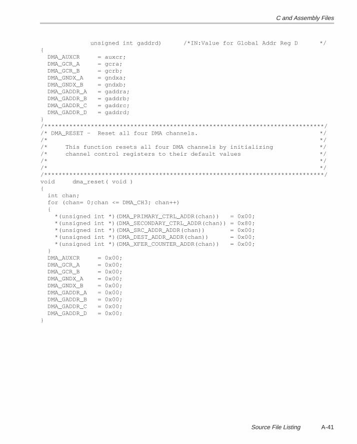
C and Assembly Files
A-41Source File Listing
unsigned int gaddrd) /*IN:Value for Global Addr Reg D */{ DMA_AUXCR = auxcr; DMA_GCR_A = gcra; DMA_GCR_B = gcrb; DMA_GNDX_A = gndxa; DMA_GNDX_B = gndxb; DMA_GADDR_A = gaddra; DMA_GADDR_B = gaddrb; DMA_GADDR_C = gaddrc; DMA_GADDR_D = gaddrd;}/******************************************************************************//* DMA_RESET – Reset all four DMA channels. *//* *//* This function resets all four DMA channels by initializing *//* channel control registers to their default values *//* *//* *//******************************************************************************/void dma_reset( void ){ int chan; for (chan= 0;chan <= DMA_CH3; chan++) { *(unsigned int *)(DMA_PRIMARY_CTRL_ADDR(chan)) = 0x00; *(unsigned int *)(DMA_SECONDARY_CTRL_ADDR(chan)) = 0x80; *(unsigned int *)(DMA_SRC_ADDR_ADDR(chan)) = 0x00; *(unsigned int *)(DMA_DEST_ADDR_ADDR(chan)) = 0x00; *(unsigned int *)(DMA_XFER_COUNTER_ADDR(chan)) = 0x00; } DMA_AUXCR = 0x00; DMA_GCR_A = 0x00; DMA_GCR_B = 0x00; DMA_GNDX_A = 0x00; DMA_GNDX_B = 0x00; DMA_GADDR_A = 0x00; DMA_GADDR_B = 0x00; DMA_GADDR_C = 0x00; DMA_GADDR_D = 0x00;}
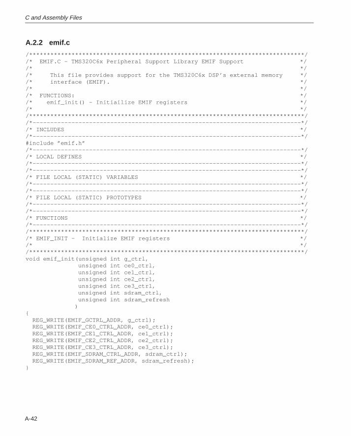
C and Assembly Files
A-42
A.2.2 emif.c
/******************************************************************************//* EMIF.C – TMS320C6x Peripheral Support Library EMIF Support *//* *//* This file provides support for the TMS320C6x DSP’s external memory *//* interface (EMIF). *//* *//* FUNCTIONS: *//* emif_init() – Initiailize EMIF registers *//* *//******************************************************************************//*––––––––––––––––––––––––––––––––––––––––––––––––––––––––––––––––––––––––––––*//* INCLUDES *//*––––––––––––––––––––––––––––––––––––––––––––––––––––––––––––––––––––––––––––*/#include ”emif.h”/*––––––––––––––––––––––––––––––––––––––––––––––––––––––––––––––––––––––––––––*//* LOCAL DEFINES *//*––––––––––––––––––––––––––––––––––––––––––––––––––––––––––––––––––––––––––––*//*––––––––––––––––––––––––––––––––––––––––––––––––––––––––––––––––––––––––––––*//* FILE LOCAL (STATIC) VARIABLES *//*––––––––––––––––––––––––––––––––––––––––––––––––––––––––––––––––––––––––––––*//*––––––––––––––––––––––––––––––––––––––––––––––––––––––––––––––––––––––––––––*//* FILE LOCAL (STATIC) PROTOTYPES *//*––––––––––––––––––––––––––––––––––––––––––––––––––––––––––––––––––––––––––––*//*––––––––––––––––––––––––––––––––––––––––––––––––––––––––––––––––––––––––––––*//* FUNCTIONS *//*––––––––––––––––––––––––––––––––––––––––––––––––––––––––––––––––––––––––––––*//******************************************************************************//* EMIF_INIT – Initialize EMIF registers *//* *//******************************************************************************/void emif_init(unsigned int g_ctrl, unsigned int ce0_ctrl, unsigned int ce1_ctrl, unsigned int ce2_ctrl, unsigned int ce3_ctrl, unsigned int sdram_ctrl, unsigned int sdram_refresh ){ REG_WRITE(EMIF_GCTRL_ADDR, g_ctrl); REG_WRITE(EMIF_CE0_CTRL_ADDR, ce0_ctrl); REG_WRITE(EMIF_CE1_CTRL_ADDR, ce1_ctrl); REG_WRITE(EMIF_CE2_CTRL_ADDR, ce2_ctrl); REG_WRITE(EMIF_CE3_CTRL_ADDR, ce3_ctrl); REG_WRITE(EMIF_SDRAM_CTRL_ADDR, sdram_ctrl); REG_WRITE(EMIF_SDRAM_REF_ADDR, sdram_refresh);}
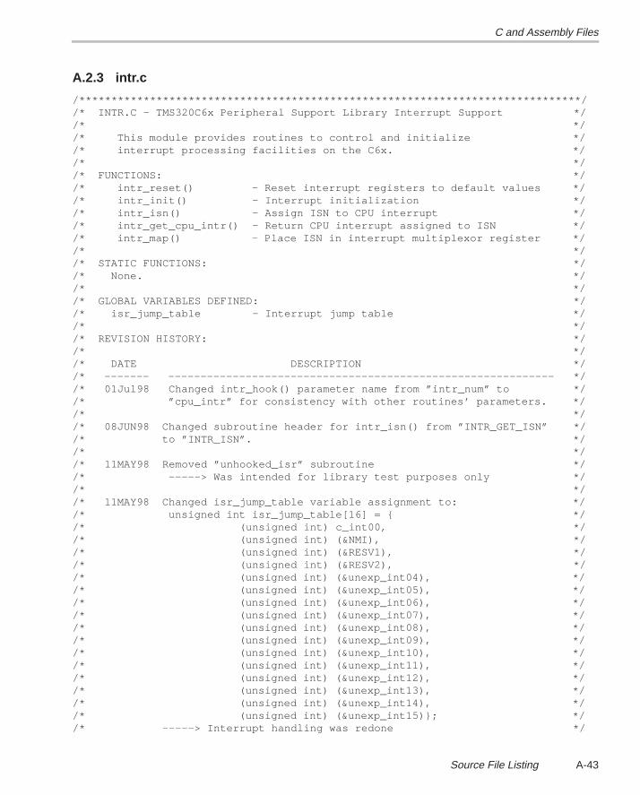
C and Assembly Files
A-43Source File Listing
A.2.3 intr.c
/******************************************************************************//* INTR.C – TMS320C6x Peripheral Support Library Interrupt Support *//* *//* This module provides routines to control and initialize *//* interrupt processing facilities on the C6x. *//* *//* FUNCTIONS: *//* intr_reset() – Reset interrupt registers to default values *//* intr_init() – Interrupt initialization *//* intr_isn() – Assign ISN to CPU interrupt *//* intr_get_cpu_intr() – Return CPU interrupt assigned to ISN *//* intr_map() – Place ISN in interrupt multiplexor register *//* *//* STATIC FUNCTIONS: *//* None. *//* *//* GLOBAL VARIABLES DEFINED: *//* isr_jump_table – Interrupt jump table *//* *//* REVISION HISTORY: *//* *//* DATE DESCRIPTION *//* ––––––– –––––––––––––––––––––––––––––––––––––––––––––––––––––––––––– *//* 01Jul98 Changed intr_hook() parameter name from ”intr_num” to *//* ”cpu_intr” for consistency with other routines’ parameters. *//* *//* 08JUN98 Changed subroutine header for intr_isn() from ”INTR_GET_ISN” *//* to ”INTR_ISN”. *//* *//* 11MAY98 Removed ”unhooked_isr” subroutine *//* –––––> Was intended for library test purposes only *//* *//* 11MAY98 Changed isr_jump_table variable assignment to: *//* unsigned int isr_jump_table[16] = { *//* (unsigned int) c_int00, *//* (unsigned int) (&NMI), *//* (unsigned int) (&RESV1), *//* (unsigned int) (&RESV2), *//* (unsigned int) (&unexp_int04), *//* (unsigned int) (&unexp_int05), *//* (unsigned int) (&unexp_int06), *//* (unsigned int) (&unexp_int07), *//* (unsigned int) (&unexp_int08), *//* (unsigned int) (&unexp_int09), *//* (unsigned int) (&unexp_int10), *//* (unsigned int) (&unexp_int11), *//* (unsigned int) (&unexp_int12), *//* (unsigned int) (&unexp_int13), *//* (unsigned int) (&unexp_int14), *//* (unsigned int) (&unexp_int15)}; *//* –––––> Interrupt handling was redone */
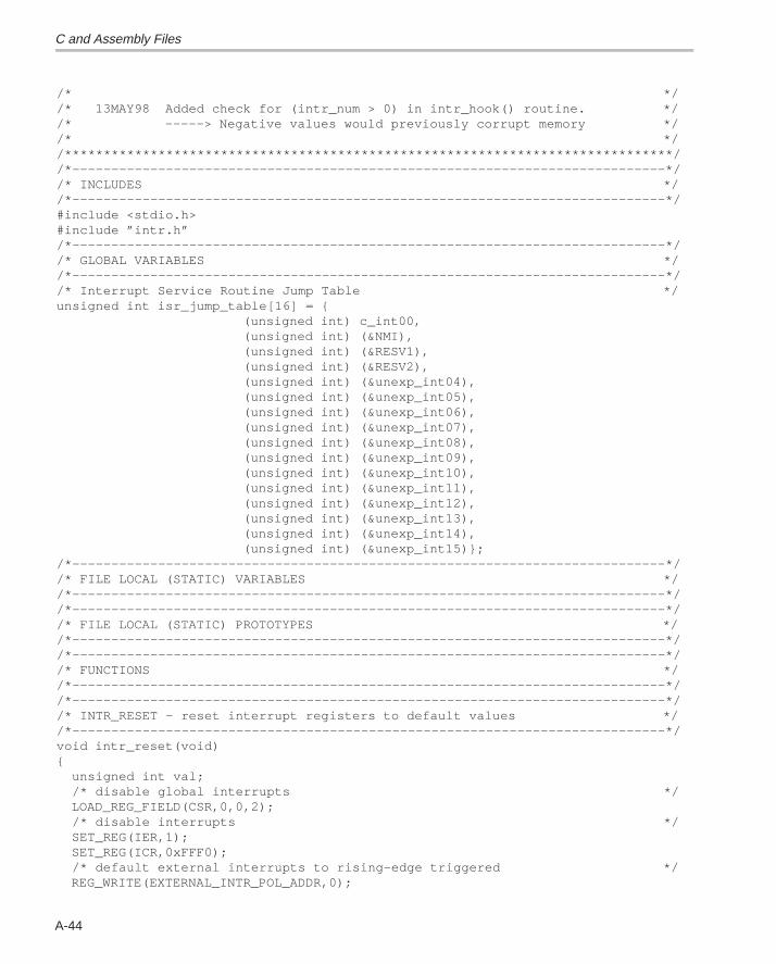
C and Assembly Files
A-44
/* *//* 13MAY98 Added check for (intr_num > 0) in intr_hook() routine. *//* –––––> Negative values would previously corrupt memory *//* *//******************************************************************************//*––––––––––––––––––––––––––––––––––––––––––––––––––––––––––––––––––––––––––––*//* INCLUDES *//*––––––––––––––––––––––––––––––––––––––––––––––––––––––––––––––––––––––––––––*/#include <stdio.h>#include ”intr.h”/*––––––––––––––––––––––––––––––––––––––––––––––––––––––––––––––––––––––––––––*//* GLOBAL VARIABLES *//*––––––––––––––––––––––––––––––––––––––––––––––––––––––––––––––––––––––––––––*//* Interrupt Service Routine Jump Table */unsigned int isr_jump_table[16] = { (unsigned int) c_int00, (unsigned int) (&NMI), (unsigned int) (&RESV1), (unsigned int) (&RESV2), (unsigned int) (&unexp_int04), (unsigned int) (&unexp_int05), (unsigned int) (&unexp_int06), (unsigned int) (&unexp_int07), (unsigned int) (&unexp_int08), (unsigned int) (&unexp_int09), (unsigned int) (&unexp_int10), (unsigned int) (&unexp_int11), (unsigned int) (&unexp_int12), (unsigned int) (&unexp_int13), (unsigned int) (&unexp_int14), (unsigned int) (&unexp_int15)};/*––––––––––––––––––––––––––––––––––––––––––––––––––––––––––––––––––––––––––––*//* FILE LOCAL (STATIC) VARIABLES *//*––––––––––––––––––––––––––––––––––––––––––––––––––––––––––––––––––––––––––––*//*––––––––––––––––––––––––––––––––––––––––––––––––––––––––––––––––––––––––––––*//* FILE LOCAL (STATIC) PROTOTYPES *//*––––––––––––––––––––––––––––––––––––––––––––––––––––––––––––––––––––––––––––*//*––––––––––––––––––––––––––––––––––––––––––––––––––––––––––––––––––––––––––––*//* FUNCTIONS *//*––––––––––––––––––––––––––––––––––––––––––––––––––––––––––––––––––––––––––––*//*––––––––––––––––––––––––––––––––––––––––––––––––––––––––––––––––––––––––––––*//* INTR_RESET – reset interrupt registers to default values *//*––––––––––––––––––––––––––––––––––––––––––––––––––––––––––––––––––––––––––––*/void intr_reset(void){ unsigned int val; /* disable global interrupts */ LOAD_REG_FIELD(CSR,0,0,2); /* disable interrupts */ SET_REG(IER,1); SET_REG(ICR,0xFFF0); /* default external interrupts to rising–edge triggered */ REG_WRITE(EXTERNAL_INTR_POL_ADDR,0);
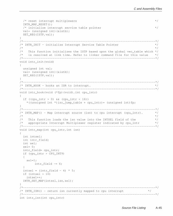
C and Assembly Files
A-45Source File Listing
/* reset interrupt multiplexers */ INTR_MAP_RESET(); /* initialize interrupt service table pointer */ val= (unsigned int)(&istb); SET_REG(ISTP,val);}/*––––––––––––––––––––––––––––––––––––––––––––––––––––––––––––––––––––––––––––*//* INTR_INIT – initialize Interrupt Service Table Pointer *//* *//* This function initializes the ISTP based upon the global vec_table which *//* is resolved at link time. Refer to linker command file for this value *//*––––––––––––––––––––––––––––––––––––––––––––––––––––––––––––––––––––––––––––*/void intr_init(void){ unsigned int val; val= (unsigned int)(&istb); SET_REG(ISTP,val);}/*––––––––––––––––––––––––––––––––––––––––––––––––––––––––––––––––––––––––––––*//* INTR_HOOK – hooks an ISR to interrupt. *//*––––––––––––––––––––––––––––––––––––––––––––––––––––––––––––––––––––––––––––*/void intr_hook(void (*fp)(void),int cpu_intr){ if ((cpu_intr > 0) && (cpu_intr < 16)) *((unsigned int *)isr_jump_table + cpu_intr)= (unsigned int)fp;}/*––––––––––––––––––––––––––––––––––––––––––––––––––––––––––––––––––––––––––––*//* INTR_MAP() – Map interrupt source (isn) to cpu interrupt (cpu_intr). *//* *//* This function loads the isn value into the INTSEL field of the *//* appropriate Interrupt Multiplexer register indicated by cpu_intr *//*––––––––––––––––––––––––––––––––––––––––––––––––––––––––––––––––––––––––––––*/void intr_map(int cpu_intr,int isn){ int intsel; int intr_field; int sel; sel= 0; intr_field= cpu_intr; if (cpu_intr > CPU_INT9) { sel=1;
intr_field –= 6; } intsel = (intr_field – 4) * 5; if (intsel > 10) intsel++; INTR_SET_MAP(intsel,isn,sel);}/*––––––––––––––––––––––––––––––––––––––––––––––––––––––––––––––––––––––––––––*//* INTR_ISN() – return isn currently mapped to cpu interrupt *//*––––––––––––––––––––––––––––––––––––––––––––––––––––––––––––––––––––––––––––*/int intr_isn(int cpu_intr)
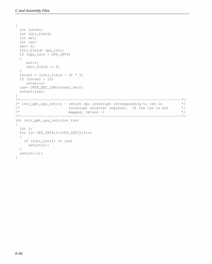
C and Assembly Files
A-46
{ int intsel; int intr_field; int sel; int isn; sel= 0; intr_field= cpu_intr; if (cpu_intr > CPU_INT9) { sel=1; intr_field –= 6; } intsel = (intr_field – 4) * 5; if (intsel > 10) intsel++; isn= INTR_GET_ISN(intsel,sel); return(isn);}/*––––––––––––––––––––––––––––––––––––––––––––––––––––––––––––––––––––––––––––*//* intr_get_cpu_intr() – return cpu interrupt corresponding to isn in *//* interrupt selecter register. If the isn is not *//* mapped, return –1 *//*––––––––––––––––––––––––––––––––––––––––––––––––––––––––––––––––––––––––––––*/int intr_get_cpu_intr(int isn){ int i; for (i= CPU_INT4;i<=CPU_INT15;i++) { if (intr_isn(i) == isn) return(i); } return(–1);}
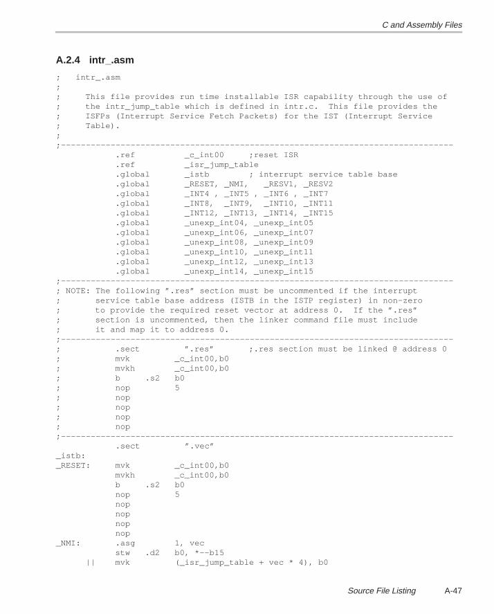
C and Assembly Files
A-47Source File Listing
A.2.4 intr_.asm
; intr_.asm;; This file provides run time installable ISR capability through the use of; the intr_jump_table which is defined in intr.c. This file provides the; ISFPs (Interrupt Service Fetch Packets) for the IST (Interrupt Service; Table).;;––––––––––––––––––––––––––––––––––––––––––––––––––––––––––––––––––––––––––––––– .ref _c_int00 ;reset ISR .ref _isr_jump_table .global _istb ; interrupt service table base .global _RESET, _NMI, _RESV1, _RESV2 .global _INT4 , _INT5 , _INT6 , _INT7 .global _INT8, _INT9, _INT10, _INT11 .global _INT12, _INT13, _INT14, _INT15 .global _unexp_int04, _unexp_int05 .global _unexp_int06, _unexp_int07 .global _unexp_int08, _unexp_int09 .global _unexp_int10, _unexp_int11 .global _unexp_int12, _unexp_int13 .global _unexp_int14, _unexp_int15;–––––––––––––––––––––––––––––––––––––––––––––––––––––––––––––––––––––––––––––––; NOTE: The following ”.res” section must be uncommented if the interrupt; service table base address (ISTB in the ISTP register) in non–zero; to provide the required reset vector at address 0. If the ”.res”; section is uncommented, then the linker command file must include; it and map it to address 0.;–––––––––––––––––––––––––––––––––––––––––––––––––––––––––––––––––––––––––––––––; .sect ”.res” ;.res section must be linked @ address 0; mvk _c_int00,b0; mvkh _c_int00,b0; b .s2 b0; nop 5; nop; nop; nop; nop;––––––––––––––––––––––––––––––––––––––––––––––––––––––––––––––––––––––––––––––– .sect ”.vec”_istb:_RESET: mvk _c_int00,b0 mvkh _c_int00,b0 b .s2 b0 nop 5 nop nop nop nop_NMI: .asg 1, vec stw .d2 b0, *––b15 || mvk (_isr_jump_table + vec * 4), b0
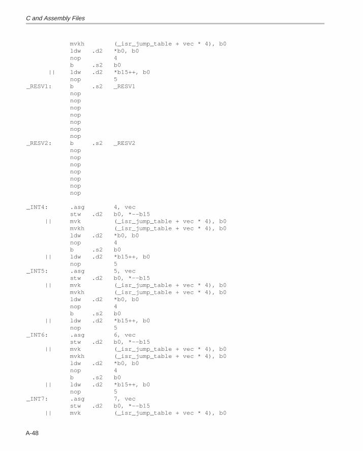
C and Assembly Files
A-48
mvkh (_isr_jump_table + vec * 4), b0 ldw .d2 *b0, b0 nop 4 b .s2 b0 || ldw .d2 *b15++, b0 nop 5_RESV1: b .s2 _RESV1 nop nop nop nop nop nop nop_RESV2: b .s2 _RESV2 nop nop nop nop nop nop nop _INT4: .asg 4, vec stw .d2 b0, *––b15 || mvk (_isr_jump_table + vec * 4), b0 mvkh (_isr_jump_table + vec * 4), b0 ldw .d2 *b0, b0 nop 4 b .s2 b0 || ldw .d2 *b15++, b0 nop 5_INT5: .asg 5, vec stw .d2 b0, *––b15 || mvk (_isr_jump_table + vec * 4), b0 mvkh (_isr_jump_table + vec * 4), b0 ldw .d2 *b0, b0 nop 4 b .s2 b0 || ldw .d2 *b15++, b0 nop 5_INT6: .asg 6, vec stw .d2 b0, *––b15 || mvk (_isr_jump_table + vec * 4), b0 mvkh (_isr_jump_table + vec * 4), b0 ldw .d2 *b0, b0 nop 4 b .s2 b0 || ldw .d2 *b15++, b0 nop 5_INT7: .asg 7, vec stw .d2 b0, *––b15 || mvk (_isr_jump_table + vec * 4), b0
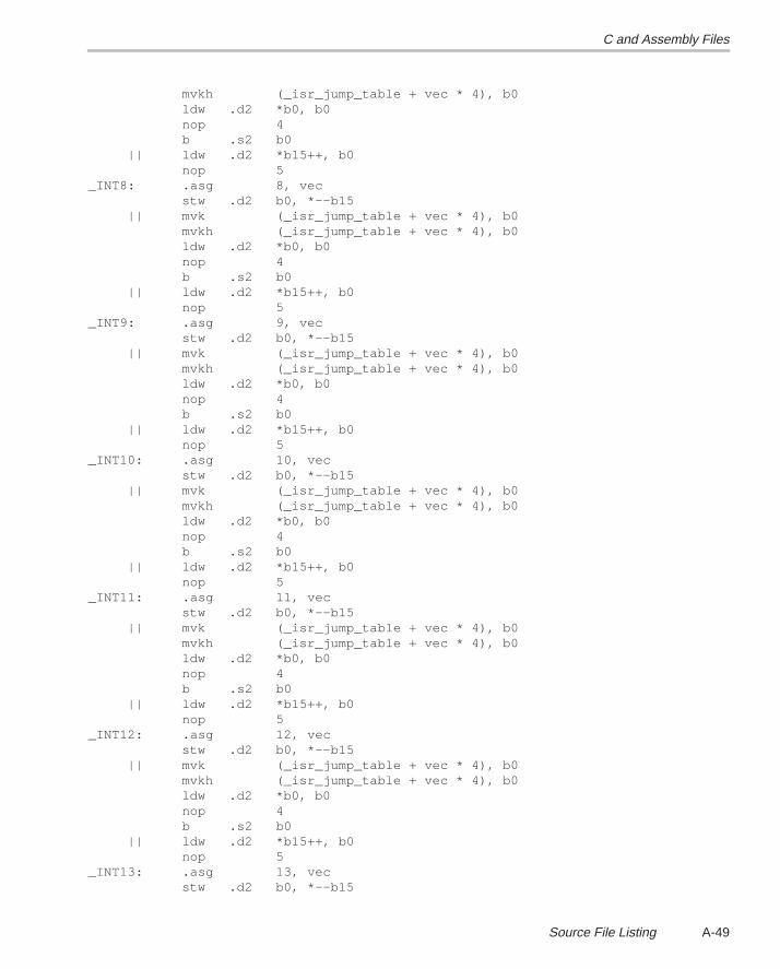
C and Assembly Files
A-49Source File Listing
mvkh (_isr_jump_table + vec * 4), b0 ldw .d2 *b0, b0 nop 4 b .s2 b0 || ldw .d2 *b15++, b0 nop 5_INT8: .asg 8, vec stw .d2 b0, *––b15 || mvk (_isr_jump_table + vec * 4), b0 mvkh (_isr_jump_table + vec * 4), b0 ldw .d2 *b0, b0 nop 4 b .s2 b0 || ldw .d2 *b15++, b0 nop 5_INT9: .asg 9, vec stw .d2 b0, *––b15 || mvk (_isr_jump_table + vec * 4), b0 mvkh (_isr_jump_table + vec * 4), b0 ldw .d2 *b0, b0 nop 4 b .s2 b0 || ldw .d2 *b15++, b0 nop 5_INT10: .asg 10, vec stw .d2 b0, *––b15 || mvk (_isr_jump_table + vec * 4), b0 mvkh (_isr_jump_table + vec * 4), b0 ldw .d2 *b0, b0 nop 4 b .s2 b0 || ldw .d2 *b15++, b0 nop 5_INT11: .asg 11, vec stw .d2 b0, *––b15 || mvk (_isr_jump_table + vec * 4), b0 mvkh (_isr_jump_table + vec * 4), b0 ldw .d2 *b0, b0 nop 4 b .s2 b0 || ldw .d2 *b15++, b0 nop 5_INT12: .asg 12, vec stw .d2 b0, *––b15 || mvk (_isr_jump_table + vec * 4), b0 mvkh (_isr_jump_table + vec * 4), b0 ldw .d2 *b0, b0 nop 4 b .s2 b0 || ldw .d2 *b15++, b0 nop 5_INT13: .asg 13, vec stw .d2 b0, *––b15
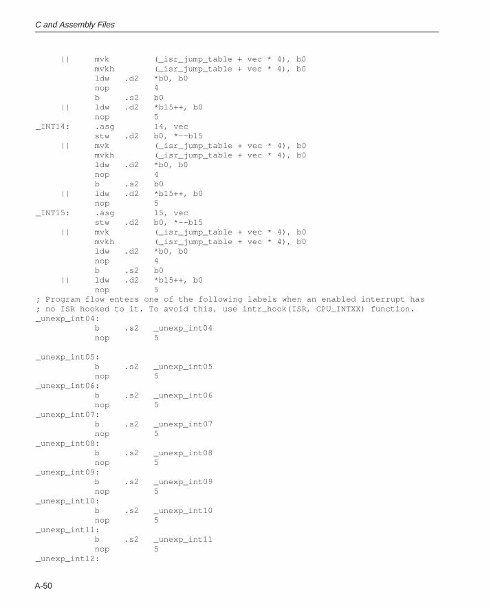
C and Assembly Files
A-50
|| mvk (_isr_jump_table + vec * 4), b0 mvkh (_isr_jump_table + vec * 4), b0 ldw .d2 *b0, b0 nop 4 b .s2 b0 || ldw .d2 *b15++, b0 nop 5_INT14: .asg 14, vec stw .d2 b0, *––b15 || mvk (_isr_jump_table + vec * 4), b0 mvkh (_isr_jump_table + vec * 4), b0 ldw .d2 *b0, b0 nop 4 b .s2 b0 || ldw .d2 *b15++, b0 nop 5_INT15: .asg 15, vec stw .d2 b0, *––b15 || mvk (_isr_jump_table + vec * 4), b0 mvkh (_isr_jump_table + vec * 4), b0 ldw .d2 *b0, b0 nop 4 b .s2 b0 || ldw .d2 *b15++, b0 nop 5; Program flow enters one of the following labels when an enabled interrupt has; no ISR hooked to it. To avoid this, use intr_hook(ISR, CPU_INTXX) function._unexp_int04: b .s2 _unexp_int04 nop 5 _unexp_int05: b .s2 _unexp_int05 nop 5_unexp_int06: b .s2 _unexp_int06 nop 5_unexp_int07: b .s2 _unexp_int07 nop 5_unexp_int08: b .s2 _unexp_int08 nop 5_unexp_int09: b .s2 _unexp_int09 nop 5_unexp_int10: b .s2 _unexp_int10 nop 5_unexp_int11: b .s2 _unexp_int11 nop 5_unexp_int12:
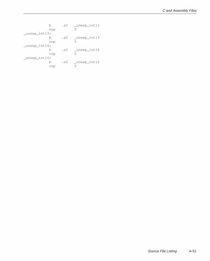
C and Assembly Files
A-51Source File Listing
b .s2 _unexp_int12 nop 5_unexp_int13: b .s2 _unexp_int13 nop 5_unexp_int14: b .s2 _unexp_int14 nop 5_unexp_int15: b .s2 _unexp_int15 nop 5
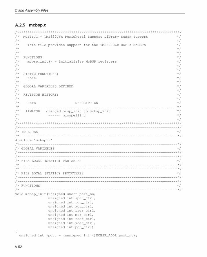
C and Assembly Files
A-52
A.2.5 mcbsp.c
/******************************************************************************//* MCBSP.C – TMS320C6x Peripheral Support Library McBSP Support *//* *//* This file provides support for the TMS320C6x DSP’s McBSPs *//* *//* *//* FUNCTIONS: *//* mcbsp_init() – initializize McBSP registers *//* *//* *//* STATIC FUNCTIONS: *//* None. *//* *//* GLOBAL VARIABLES DEFINED *//* *//* REVISION HISTORY: *//* *//* DATE DESCRIPTION *//* ––––––– ––––––––––––––––––––––––––––––––––––––––––––––––––––––––––––– *//* 11MAY98 changed mcsp_init to mcbsp_init *//* –––––> misspelling *//* *//******************************************************************************//*––––––––––––––––––––––––––––––––––––––––––––––––––––––––––––––––––––––––––––*//* INCLUDES *//*––––––––––––––––––––––––––––––––––––––––––––––––––––––––––––––––––––––––––––*/#include ”mcbsp.h”/*––––––––––––––––––––––––––––––––––––––––––––––––––––––––––––––––––––––––––––*//* GLOBAL VARIABLES *//*––––––––––––––––––––––––––––––––––––––––––––––––––––––––––––––––––––––––––––*//*––––––––––––––––––––––––––––––––––––––––––––––––––––––––––––––––––––––––––––*//* FILE LOCAL (STATIC) VARIABLES *//*––––––––––––––––––––––––––––––––––––––––––––––––––––––––––––––––––––––––––––*//*––––––––––––––––––––––––––––––––––––––––––––––––––––––––––––––––––––––––––––*//* FILE LOCAL (STATIC) PROTOTYPES *//*––––––––––––––––––––––––––––––––––––––––––––––––––––––––––––––––––––––––––––*//*––––––––––––––––––––––––––––––––––––––––––––––––––––––––––––––––––––––––––––*//* FUNCTIONS *//*––––––––––––––––––––––––––––––––––––––––––––––––––––––––––––––––––––––––––––*/void mcbsp_init(unsigned short port_no, unsigned int spcr_ctrl, unsigned int rcr_ctrl, unsigned int xcr_ctrl, unsigned int srgr_ctrl, unsigned int mcr_ctrl, unsigned int rcer_ctrl, unsigned int xcer_ctrl, unsigned int pcr_ctrl){ unsigned int *port = (unsigned int *)MCBSP_ADDR(port_no);
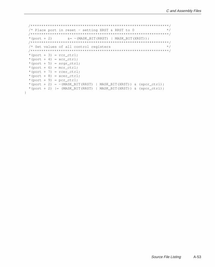
C and Assembly Files
A-53Source File Listing
/****************************************************************/ /* Place port in reset – setting XRST & RRST to 0 */ /****************************************************************/ *(port + 2) &= ~(MASK_BIT(RRST) | MASK_BIT(XRST)); /****************************************************************/ /* Set values of all control registers */ /****************************************************************/ *(port + 3) = rcr_ctrl; *(port + 4) = xcr_ctrl; *(port + 5) = srgr_ctrl; *(port + 6) = mcr_ctrl; *(port + 7) = rcer_ctrl; *(port + 8) = xcer_ctrl; *(port + 9) = pcr_ctrl; *(port + 2) = ~(MASK_BIT(RRST) | MASK_BIT(XRST)) & (spcr_ctrl); *(port + 2) |= (MASK_BIT(RRST) | MASK_BIT(XRST)) & (spcr_ctrl);}
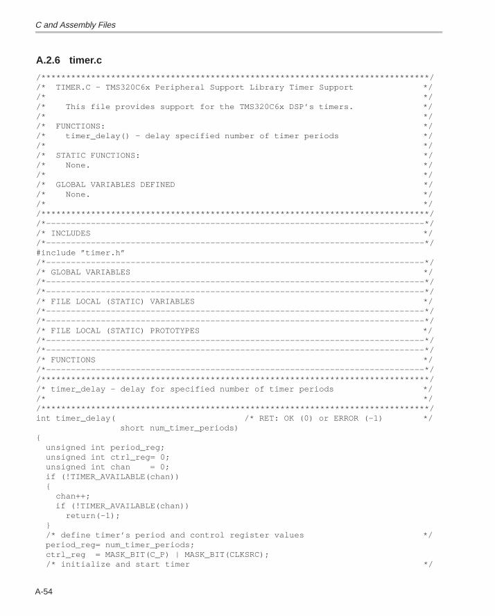
C and Assembly Files
A-54
A.2.6 timer.c
/******************************************************************************//* TIMER.C – TMS320C6x Peripheral Support Library Timer Support *//* *//* This file provides support for the TMS320C6x DSP’s timers. *//* *//* FUNCTIONS: *//* timer_delay() – delay specified number of timer periods *//* *//* STATIC FUNCTIONS: *//* None. *//* *//* GLOBAL VARIABLES DEFINED *//* None. *//* *//******************************************************************************//*––––––––––––––––––––––––––––––––––––––––––––––––––––––––––––––––––––––––––––*//* INCLUDES *//*––––––––––––––––––––––––––––––––––––––––––––––––––––––––––––––––––––––––––––*/#include ”timer.h”/*––––––––––––––––––––––––––––––––––––––––––––––––––––––––––––––––––––––––––––*//* GLOBAL VARIABLES *//*––––––––––––––––––––––––––––––––––––––––––––––––––––––––––––––––––––––––––––*//*––––––––––––––––––––––––––––––––––––––––––––––––––––––––––––––––––––––––––––*//* FILE LOCAL (STATIC) VARIABLES *//*––––––––––––––––––––––––––––––––––––––––––––––––––––––––––––––––––––––––––––*//*––––––––––––––––––––––––––––––––––––––––––––––––––––––––––––––––––––––––––––*//* FILE LOCAL (STATIC) PROTOTYPES *//*––––––––––––––––––––––––––––––––––––––––––––––––––––––––––––––––––––––––––––*//*––––––––––––––––––––––––––––––––––––––––––––––––––––––––––––––––––––––––––––*//* FUNCTIONS *//*––––––––––––––––––––––––––––––––––––––––––––––––––––––––––––––––––––––––––––*//******************************************************************************//* timer_delay – delay for specified number of timer periods *//* *//******************************************************************************/int timer_delay( /* RET: OK (0) or ERROR (–1) */ short num_timer_periods){ unsigned int period_reg; unsigned int ctrl_reg= 0; unsigned int chan = 0; if (!TIMER_AVAILABLE(chan)) { chan++; if (!TIMER_AVAILABLE(chan)) return(–1); } /* define timer’s period and control register values */ period_reg= num_timer_periods; ctrl_reg = MASK_BIT(C_P) | MASK_BIT(CLKSRC); /* initialize and start timer */

C and Assembly Files
A-55Source File Listing
TIMER_INIT(chan,ctrl_reg,period_reg,0); TIMER_START(chan); /* poll for high to low transition */ while (!(TIMER_GET_TSTAT(chan))){}; while (TIMER_GET_TSTAT(chan)) {}; /* stop timer and return 0 to indicate success */ TIMER_STOP(chan); return(0);}
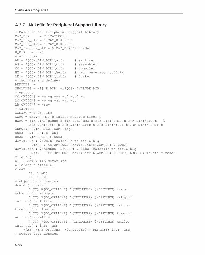
C and Assembly Files
A-56
A.2.7 Makefile for Peripheral Support Library
# Makefile for Peripheral Support LibraryC6X_DIR = C:\C6XTOOLSC6X_BIN_DIR = $(C6X_DIR)\binC6X_LIB_DIR = $(C6X_DIR)\libC6X_INCLUDE_DIR = $(C6X_DIR)\includeH_DIR = ..\h# utilitiesAR = $(C6X_BIN_DIR)\ar6x # archiverAS = $(C6X_BIN_DIR)\cl6x # assemblerCC = $(C6X_BIN_DIR)\cl6x # compilerHX = $(C6X_BIN_DIR)\hex6x # hex conversion utilityLK = $(C6X_BIN_DIR)\lnk6x # linker# includes and definesDEFINES =INCLUDES = –i$(H_DIR) –i$(C6X_INCLUDE_DIR)# optionsCC_OPTIONS = –c –q –ss –o0 –op0 –gAS_OPTIONS = –c –q –al –as –gsAR_OPTIONS = –rqv# targetsASMSRC = intr_.asmCSRC = dma.c emif.c intr.c mcbsp.c timer.cHSRC = $(H_DIR)\cache.h $(H_DIR)\dma.h $(H_DIR)\emif.h $(H_DIR)\hpi.h \ $(H_DIR)\intr.h $(H_DIR)\mcbsp.h $(H_DIR)\regs.h $(H_DIR)\timer.hASMOBJ = $(ASMSRC:.asm=.obj)COBJ = $(CSRC:.c=.obj)OBJS = $(ASMOBJ) $(COBJ)dev6x.lib : $(OBJS) makefile makefile.big $(AR) $(AR_OPTIONS) dev6x.lib $(ASMOBJ) $(COBJ)dev6x.src : $(ASMSRC) $(CSRC) $(HSRC) makefile makefile.big $(AR) $(AR_OPTIONS) dev6x.src $(ASMSRC) $(HSRC) $(CSRC) makefile make-file.bigall : dev6x.lib dev6x.srcallclean : clean allclean :
del *.objdel *.lst
# object dependenciesdma.obj : dma.c
$(CC) $(CC_OPTIONS) $(INCLUDES) $(DEFINES) dma.cmcbsp.obj : mcbsp.c
$(CC) $(CC_OPTIONS) $(INCLUDES) $(DEFINES) mcbsp.cintr.obj : intr.c
$(CC) $(CC_OPTIONS) $(INCLUDES) $(DEFINES) intr.ctimer.obj : timer.c
$(CC) $(CC_OPTIONS) $(INCLUDES) $(DEFINES) timer.cemif.obj : emif.c
$(CC) $(CC_OPTIONS) $(INCLUDES) $(DEFINES) emif.cintr_.obj : intr_.asm $(AS) $(AS_OPTIONS) $(INCLUDES) $(DEFINES) intr_.asm# source dependencies
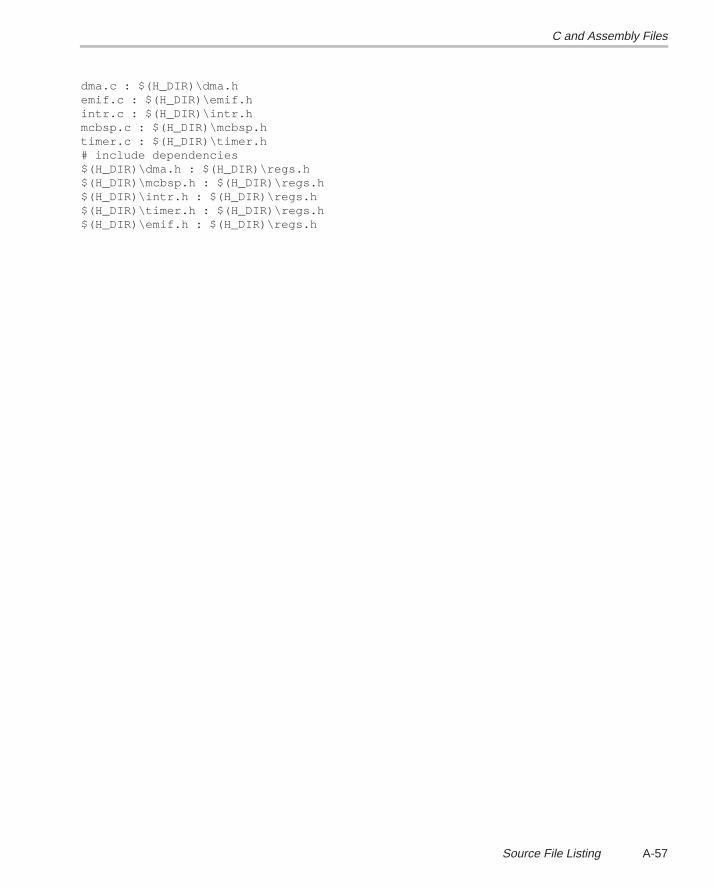
C and Assembly Files
A-57Source File Listing
dma.c : $(H_DIR)\dma.hemif.c : $(H_DIR)\emif.hintr.c : $(H_DIR)\intr.hmcbsp.c : $(H_DIR)\mcbsp.htimer.c : $(H_DIR)\timer.h# include dependencies$(H_DIR)\dma.h : $(H_DIR)\regs.h$(H_DIR)\mcbsp.h : $(H_DIR)\regs.h$(H_DIR)\intr.h : $(H_DIR)\regs.h$(H_DIR)\timer.h : $(H_DIR)\regs.h$(H_DIR)\emif.h : $(H_DIR)\regs.h
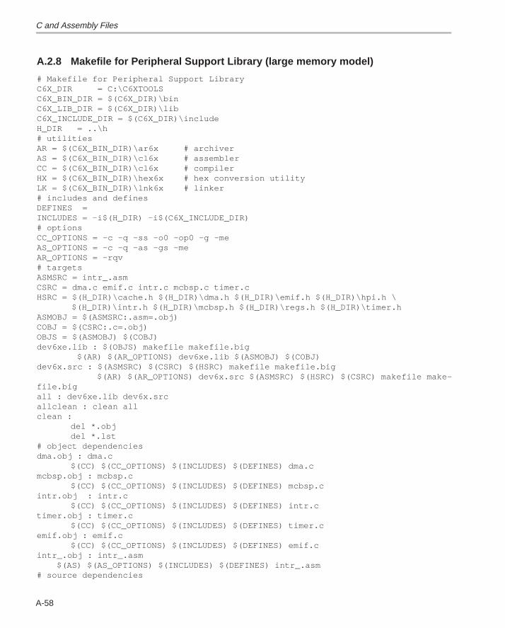
C and Assembly Files
A-58
A.2.8 Makefile for Peripheral Support Library (large memory model)
# Makefile for Peripheral Support LibraryC6X_DIR = C:\C6XTOOLSC6X_BIN_DIR = $(C6X_DIR)\binC6X_LIB_DIR = $(C6X_DIR)\libC6X_INCLUDE_DIR = $(C6X_DIR)\includeH_DIR = ..\h# utilitiesAR = $(C6X_BIN_DIR)\ar6x # archiverAS = $(C6X_BIN_DIR)\cl6x # assemblerCC = $(C6X_BIN_DIR)\cl6x # compilerHX = $(C6X_BIN_DIR)\hex6x # hex conversion utilityLK = $(C6X_BIN_DIR)\lnk6x # linker# includes and definesDEFINES =INCLUDES = –i$(H_DIR) –i$(C6X_INCLUDE_DIR)# optionsCC_OPTIONS = –c –q –ss –o0 –op0 –g –meAS_OPTIONS = –c –q –as –gs –meAR_OPTIONS = –rqv# targetsASMSRC = intr_.asmCSRC = dma.c emif.c intr.c mcbsp.c timer.cHSRC = $(H_DIR)\cache.h $(H_DIR)\dma.h $(H_DIR)\emif.h $(H_DIR)\hpi.h \ $(H_DIR)\intr.h $(H_DIR)\mcbsp.h $(H_DIR)\regs.h $(H_DIR)\timer.hASMOBJ = $(ASMSRC:.asm=.obj)COBJ = $(CSRC:.c=.obj)OBJS = $(ASMOBJ) $(COBJ)dev6xe.lib : $(OBJS) makefile makefile.big $(AR) $(AR_OPTIONS) dev6xe.lib $(ASMOBJ) $(COBJ)dev6x.src : $(ASMSRC) $(CSRC) $(HSRC) makefile makefile.big $(AR) $(AR_OPTIONS) dev6x.src $(ASMSRC) $(HSRC) $(CSRC) makefile make-file.bigall : dev6xe.lib dev6x.srcallclean : clean allclean :
del *.objdel *.lst
# object dependenciesdma.obj : dma.c
$(CC) $(CC_OPTIONS) $(INCLUDES) $(DEFINES) dma.cmcbsp.obj : mcbsp.c
$(CC) $(CC_OPTIONS) $(INCLUDES) $(DEFINES) mcbsp.cintr.obj : intr.c
$(CC) $(CC_OPTIONS) $(INCLUDES) $(DEFINES) intr.ctimer.obj : timer.c
$(CC) $(CC_OPTIONS) $(INCLUDES) $(DEFINES) timer.cemif.obj : emif.c
$(CC) $(CC_OPTIONS) $(INCLUDES) $(DEFINES) emif.cintr_.obj : intr_.asm $(AS) $(AS_OPTIONS) $(INCLUDES) $(DEFINES) intr_.asm# source dependencies

C and Assembly Files
A-59Source File Listing
dma.c : $(H_DIR)\dma.hemif.c : $(H_DIR)\emif.hintr.c : $(H_DIR)\intr.hmcbsp.c : $(H_DIR)\mcbsp.htimer.c : $(H_DIR)\timer.h# include dependencies$(H_DIR)\dma.h : $(H_DIR)\regs.h$(H_DIR)\mcbsp.h : $(H_DIR)\regs.h$(H_DIR)\intr.h : $(H_DIR)\regs.h$(H_DIR)\timer.h : $(H_DIR)\regs.h$(H_DIR)\emif.h : $(H_DIR)\regs.h
B-1
Appendix A
Glossary
Aaddress: The location of program code or data stored; an individually
accessible memory location.
A-law companding: See compress and expand (compand).
assembler: A software program that creates a machine language programfrom a source file that contains assembly language instructions, direc-tives, and macros. The assembler substitutes absolute operation codesfor symbolic operation codes and absolute or relocatable addresses forsymbolic addresses.
assert: To make a digital logic device pin active. If the pin is active low, thena low voltage on the pin asserts it. If the pin is active high, then a highvoltage asserts it.
Bbit: A binary digit, either a 0 or 1.
big endian: An addressing protocol in which bytes are numbered from leftto right within a word. More significant bytes in a word have lower num-bered addresses. Endian ordering is specific to hardware and is deter-mined at reset. See also little endian.
block: The three least significant bits of the program address. These corre-spond to the address within a fetch packet of the first instruction beingaddressed.
boot: The process of loading a program into program memory.
boot mode: The method of loading a program into program memory. The’C6x DSP supports booting from external ROM or the host port interface(HPI).
byte: A sequence of eight adjacent bits operated upon as a unit.
Appendix B
Glossary
B-2
C
cache: A fast storage buffer in the central processing unit of a computer.
cache controller: System component that coordinates program accessesbetween CPU program fetch mechanism, cache, and external memory.
central processing unit (CPU): The portion of the processor involved inarithmetic, shifting, and Boolean logic operations, as well as the genera-tion of data- and program-memory addresses. The CPU includes thecentral arithmetic logic unit (CALU), the multiplier, and the auxiliary regis-ter arithmetic unit (ARAU).
clock cycle: A periodic or sequence of events based on the input from theexternal clock.
clock modes: Options used by the clock generator to change the internalCPU clock frequency to a fraction or multiple of the frequency of the inputclock signal.
code: A set of instructions written to perform a task; a computer program orpart of a program.
coder-decoder or compression/decompression (codec): A device thatcodes in one direction of transmission and decodes in another directionof transmission.
compiler: A computer program that translates programs in a high-level lan-guage into their assembly-language equivalents.
compress and expand (compand): A quantization scheme for audio sig-nals in which the input signal is compressed and then, after processing,is reconstructed at the output by expansion. There are two distinct com-panding schemes: A-law (used in Europe) and µ-law (used in the UnitedStates).
control register: A register that contains bit fields that define the way a de-vice operates.
control register file: A set of control registers.
Glossary
B-3Glossary
D
device ID: Configuration register that identifies each peripheral componentinterconnect (PCI).
digital signal processor (DSP): A semiconductor that turns analog sig-nals—such as sound or light—into digital signals, which are discrete ordiscontinuous electrical impulses, so that they can be manipulated.
direct memory access (DMA): A mechanism whereby a device other thanthe host processor contends for and receives mastery of the memory busso that data transfers can take place independent of the host.
DMA operation: A series of DMA data transfers.
DMA source: The module where the DMA data originates. DMA data is readfrom the DMA source.
DMA transfer: The process of transferring data from one part of memory toanother. Each DMA transfer consists of a read bus cycle (source to DMAholding register) and a write bus cycle (DMA holding register to destina-tion).
E
evaluation module (EVM): A board and software tools that allow the userto evaluate a specific device.
external interrupt: A hardware interrupt triggered by a specific value on apin.
external memory interface (EMIF): Microprocessor hardware that is usedto read to and write from off-chip memory.
F
fetch packet: A contiguous 8-word series of instructions fetched by the CPUand aligned on an 8-word boundary.
flag: A binary status indicator whose state indicates whether a particularcondition has occurred or is in effect.
frame: An 8-word space in the cache RAMs. Each fetch packet in the cacheresides in only one frame. A cache update loads a frame with the re-quested fetch packet. The cache contains 512 frames.
Glossary
B-4
Gglobal interrupt enable bit (GIE): A bit in the control status register (CSR)
that is used to enable or disable maskable interrupts.
Hhost: A device to which other devices (peripherals) are connected and that
generally controls those devices.
host port interface (HPI): A parallel interface that the CPU uses to commu-nicate with a host processor.
Iindex: A relative offset in the program address that specifies which of the
512 frames in the cache into which the current access is mapped.
indirect addressing: An addressing mode in which an address points toanother pointer rather than to the actual data; this mode is prohibited inRISC architecture.
instruction fetch packet: A group of up to eight instructions held in memoryfor execution by the CPU.
internal interrupt: A hardware interrupt caused by an on-chip peripheral.
interrupt: A signal sent by hardware or software to a processor requestingattention. An interrupt tells the processor to suspend its current opera-tion, save the current task status, and perform a particular set of instruc-tions. Interrupts communicate with the operating system and prioritizetasks to be performed.
interrupt service fetch packet (ISFP): A fetch packet used to service inter-rupts. If eight instructions are insufficient, the user must branch out of thisblock for additional interrupt service. If the delay slots of the branch donot reside within the ISFP, execution continues from execute packets inthe next fetch packet (the next ISFP).
interrupt service routine (ISR): A module of code that is executed in re-sponse to a hardware or software interrupt.
Internal peripherals: Devices connected to and controlled by a host device.The ’C6x internal peripherals include the direct memory access (DMA)controller, multichannel buffered serial ports (McBSPs), host port inter-face (HPI), external memory-interface (EMIF), and runtime support tim-ers.
Glossary
B-5Glossary
Lleast significant bit (LSB): The lowest-order bit in a word.
linker: A software tool that combines object files to form an object module,which can be loaded into memory and executed.
little endian: An addressing protocol in which bytes are numbered from rightto left within a word. More significant bytes in a word have higher-num-bered addresses. Endian ordering is specific to hardware and is deter-mined at reset. See also big endian.
Mµ-law companding: See compress and expand (compand).
maskable interrupt : A hardware interrupt that can be enabled or disabledthrough software.
memory map: A graphical representation of a computer system’s memory,showing the locations of program space, data space, reserved space,and other memory-resident elements.
memory-mapped register: An on-chip register mapped to an address inmemory. Some memory-mapped registers are mapped to data memory,and some are mapped to input/output memory.
most significant bit (MSB): The highest order bit in a word.
multichannel buffered serial port (McBSP): An on-chip full-duplex circuitthat provides direct serial communication through several channels toexternal serial devices.
multiplexer: A device for selecting one of several available signals.
Nnonmaskable interrupt (NMI): An interrupt that can be neither masked nor
disabled.
Oobject file: A file that has been assembled or linked and contains machine
language object code.
off chip: A state of being external to a device.
on chip: A state of being internal to a device.
Glossary
B-6
P
peripheral: A device connected to and usually controlled by a host device.-
program cache: A fast memory cache for storing program instructions al-lowing for quick execution.
program memory: Memory accessed through the ‘C6x’s program fetch in-terface.
R
random-access memory (RAM): A type of memory device in which theindividual locations can be accessed in any order.
register: A small area of high speed memory located within a processor orelectronic device that is used for temporarily storing data or instructions.Each register is given a name, contains a few bytes of information, andis referenced by programs.
reduced-instruction-set computer (RISC): A computer whose instructionset and related decode mechanism are much simpler than those of micro-programmed complex instruction set computers. The result is a higherinstruction throughput and a faster real-time interrupt service responsefrom a smaller, cost-effective chip.
reset: A means of bringing the CPU to a known state by setting the registersand control bits to predetermined values and signaling execution to startat a specified address.
S
synchronous-burst static random-access memory (SBSRAM): RAMwhose contents does not have to be refreshed periodically. Transfer ofdata is at a fixed rate relative to the clock speed of the device, but thespeed is increased.
synchronous dynamic random-access memory (SDRAM): RAM whosecontents is refreshed periodically so the data is not lost. Transfer of datais at a fixed rate relative to the clock speed of the device.
syntax: The grammatical and structural rules of a language. All higher-levelprogramming languages possess a formal syntax.
Glossary
B-7Glossary
T
tag: The 18 most significant bits of the program address. This value corre-sponds to the physical address of the fetch packet that is in that frame.
timer: A programmable peripheral used to generate pulses or to timeevents.
W
word: A multiple of eight bits that is operated upon as a unit. For the ‘C6x,a word is 32 bits in length.
C-1
Appendix A
Summary of Updates in this Document
This appendix provides a summary of the updates in this version of the docu-ment. Updates within paragraphs appear in a bold typeface .
Page: Change or Add:
1-2 Change the first paragraph of section 1.1, Source Files Included in Library.
The ’C6x peripheral support library consists of several header, C, andassembly source files. These are supplied to the user in the source filedev6x.src . The following header files included in dev6x.src provide accessto device library macro definitions and functions:
Change the second paragraph of section 1.1, Source Files Included in Library.
There are a few additional C and assembly source files that are used to buildthe dev6x.lib library file, which is linked into user code. These files include:
Change the first paragraph of section 1.2, Building the TMS320C6x Peripheral SupportLibrary.
You must build the ’C6x peripheral support (object) library before referencingit in the linker command line. The options selected during compile must matchthose that you used in building the application code. For instance, if your codeis built in big-endian mode with the large memory model, the entire peripheralsupport library must also be built with these options. The following exampleextracts source files from dev6x.src , compiles with the big-endian (–me) andlarge-memory-model (–ml) options, and archives the resulting object files toproduce the peripheral support library, dev6x.lib :
Change the code example in section 1.2, Building the TMS320C6x Peripheral SupportLibrary.
ar6x –x dev6x.src ; extracts source files from archive
cl6x –me –ml *.c*.asm ; compile c and asm source files
ar6x –r dev6x.lib *.obj ; create object library dev6x.lib
Change the first sentence of the second paragraph in section 1.2, Building theTMS320C6x Peripheral Support Library.
You can use many other compiler options to compile the dev6x.lib library. Formore information ...
Appendix C
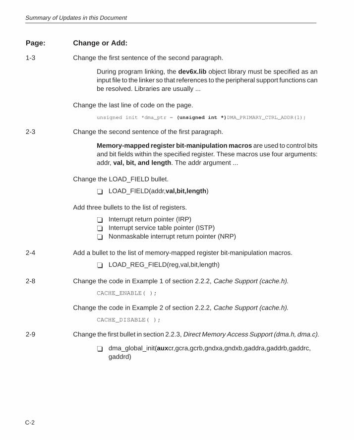
Summary of Updates in this Document
C-2
Page: Change or Add:
1-3 Change the first sentence of the second paragraph.
During program linking, the dev6x.lib object library must be specified as aninput file to the linker so that references to the peripheral support functions canbe resolved. Libraries are usually ...
Change the last line of code on the page.
unsigned init *dma_ptr = (unsigned int *) DMA_PRIMARY_CTRL_ADDR(1);
2-3 Change the second sentence of the first paragraph.
Memory-mapped register bit-manipulation macros are used to control bitsand bit fields within the specified register. These macros use four arguments:addr, val, bit, and length . The addr argument ...
Change the LOAD_FIELD bullet.
� LOAD_FIELD(addr,val,bit,length )
Add three bullets to the list of registers.
� Interrupt return pointer (IRP)� Interrupt service table pointer (ISTP)� Nonmaskable interrupt return pointer (NRP)
2-4 Add a bullet to the list of memory-mapped register bit-manipulation macros.
� LOAD_REG_FIELD(reg,val,bit,length)
2-8 Change the code in Example 1 of section 2.2.2, Cache Support (cache.h).
CACHE_ENABLE( );
Change the code in Example 2 of section 2.2.2, Cache Support (cache.h).
CACHE_DISABLE( );
2-9 Change the first bullet in section 2.2.3, Direct Memory Access Support (dma.h, dma.c).
� dma_global_init(auxcr,gcra,gcrb,gndxa,gndxb,gaddra,gaddrb,gaddrc,gaddrd)
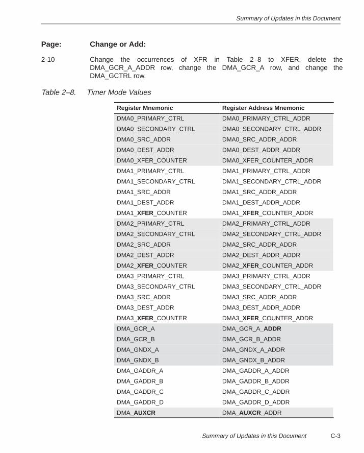
Summary of Updates in this Document
C-3Summary of Updates in this Document
Page: Change or Add:
2-10 Change the occurrences of XFR in Table 2–8 to XFER, delete theDMA_GCR_A_ADDR row, change the DMA_GCR_A row, and change theDMA_GCTRL row.
Table 2–8. Timer Mode Values
Register Mnemonic Register Address Mnemonic
DMA0_PRIMARY_CTRL DMA0_PRIMARY_CTRL_ADDR
DMA0_SECONDARY_CTRL DMA0_SECONDARY_CTRL_ADDR
DMA0_SRC_ADDR DMA0_SRC_ADDR_ADDR
DMA0_DEST_ADDR DMA0_DEST_ADDR_ADDR
DMA0_XFER_COUNTER DMA0_XFER_COUNTER_ADDR
DMA1_PRIMARY_CTRL DMA1_PRIMARY_CTRL_ADDR
DMA1_SECONDARY_CTRL DMA1_SECONDARY_CTRL_ADDR
DMA1_SRC_ADDR DMA1_SRC_ADDR_ADDR
DMA1_DEST_ADDR DMA1_DEST_ADDR_ADDR
DMA1_XFER_COUNTER DMA1_XFER_COUNTER_ADDR
DMA2_PRIMARY_CTRL DMA2_PRIMARY_CTRL_ADDR
DMA2_SECONDARY_CTRL DMA2_SECONDARY_CTRL_ADDR
DMA2_SRC_ADDR DMA2_SRC_ADDR_ADDR
DMA2_DEST_ADDR DMA2_DEST_ADDR_ADDR
DMA2_XFER_COUNTER DMA2_XFER_COUNTER_ADDR
DMA3_PRIMARY_CTRL DMA3_PRIMARY_CTRL_ADDR
DMA3_SECONDARY_CTRL DMA3_SECONDARY_CTRL_ADDR
DMA3_SRC_ADDR DMA3_SRC_ADDR_ADDR
DMA3_DEST_ADDR DMA3_DEST_ADDR_ADDR
DMA3_XFER_COUNTER DMA3_XFER_COUNTER_ADDR
DMA_GCR_A DMA_GCR_A_ADDR
DMA_GCR_B DMA_GCR_B_ADDR
DMA_GNDX_A DMA_GNDX_A_ADDR
DMA_GNDX_B DMA_GNDX_B_ADDR
DMA_GADDR_A DMA_GADDR_A_ADDR
DMA_GADDR_B DMA_GADDR_B_ADDR
DMA_GADDR_C DMA_GADDR_C_ADDR
DMA_GADDR_D DMA_GADDR_D_ADDR
DMA_AUXCR DMA_AUXCR_ADDR
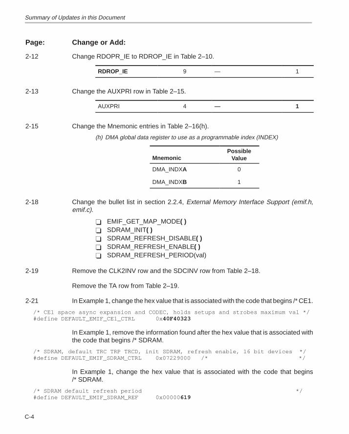
Summary of Updates in this Document
C-4
Page: Change or Add:
2-12 Change RDOPR_IE to RDROP_IE in Table 2–10.
RDROP_IE 9 — 1
2-13 Change the AUXPRI row in Table 2–15.
AUXPRI 4 — 1
2-15 Change the Mnemonic entries in Table 2–16(h).
(h) DMA global data register to use as a programmable index (INDEX)
MnemonicPossible
Value
DMA_INDXA 0
DMA_INDXB 1
2-18 Change the bullet list in section 2.2.4, External Memory Interface Support (emif.h,emif.c).
� EMIF_GET_MAP_MODE( )� SDRAM_INIT( )� SDRAM_REFRESH_DISABLE( )� SDRAM_REFRESH_ENABLE( )� SDRAM_REFRESH_PERIOD(val)
2-19 Remove the CLK2INV row and the SDCINV row from Table 2–18.
Remove the TA row from Table 2–19.
2-21 In Example 1, change the hex value that is associated with the code that begins /* CE1.
/* CE1 space async expansion and CODEC, holds setups and strobes maximum val */#define DEFAULT_EMIF_CE1_CTRL 0x 40F40323
In Example 1, remove the information found after the hex value that is associated withthe code that begins /* SDRAM.
/* SDRAM, default TRC TRP TRCD, init SDRAM, refresh enable, 16 bit devices */#define DEFAULT_EMIF_SDRAM_CTRL 0x07229000 /* */
In Example 1, change the hex value that is associated with the code that begins/* SDRAM.
/* SDRAM default refresh period */#define DEFAULT_EMIF_SDRAM_REF 0x00000 619
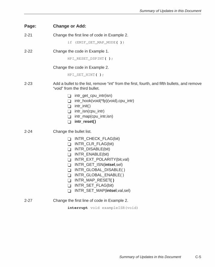
Summary of Updates in this Document
C-5Summary of Updates in this Document
Page: Change or Add:
2-21 Change the first line of code in Example 2.
if (EMIF_GET_MAP_MODE ( ) )
2-22 Change the code in Example 1.
HPI_RESET_DSPINT( ) ;
Change the code in Example 2.
HPI_SET_HINT ( ) ;
2-23 Add a bullet to the list, remove “int” from the first, fourth, and fifth bullets, and remove“void” from the third bullet.
� intr_get_cpu_intr(isn)� intr_hook(void(*fp)(void),cpu_intr)� intr_init( )� intr_isn(cpu_intr)� intr_map(cpu_intr,isn)� intr_reset()
2-24 Change the bullet list.
� INTR_CHECK_FLAG(bit)� INTR_CLR_FLAG(bit)� INTR_DISABLE(bit)� INTR_ENABLE(bit)� INTR_EXT_POLARITY(bit,val)� INTR_GET_ISN(intsel ,sel)� INTR_GLOBAL_DISABLE( )� INTR_GLOBAL_ENABLE( )� INTR_MAP_RESET( )� INTR_SET_FLAG(bit)� INTR_SET_MAP(intsel ,val,sel)
2-27 Change the first line of code in Example 2.
interrupt void exampleISR(void)
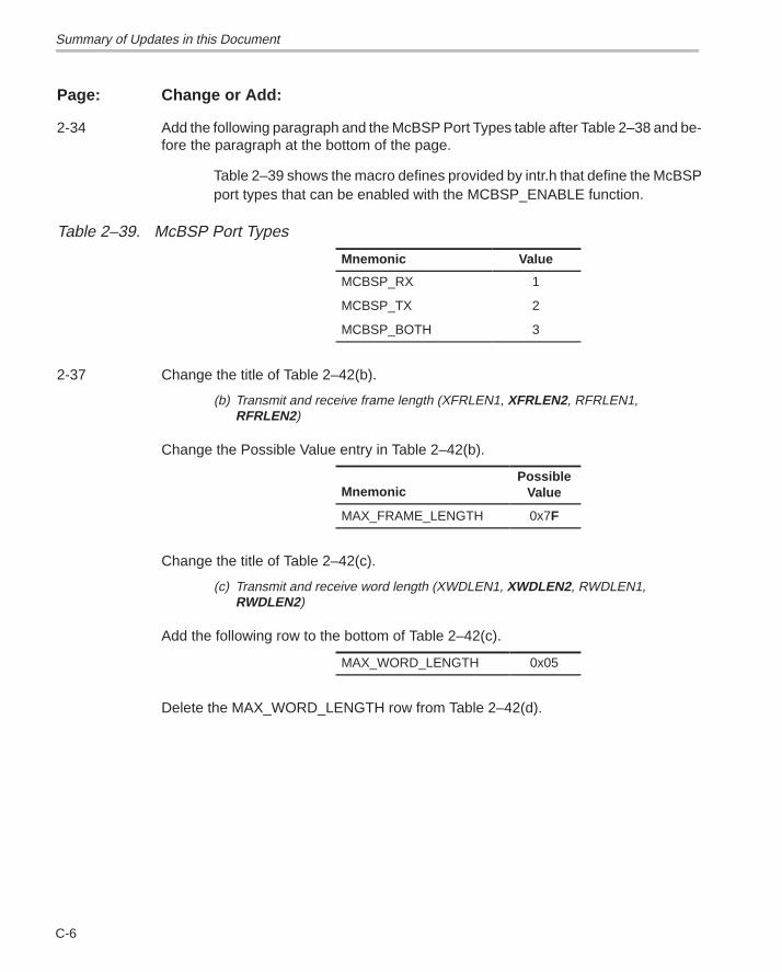
Summary of Updates in this Document
C-6
Page: Change or Add:
2-34 Add the following paragraph and the McBSP Port Types table after Table 2–38 and be-fore the paragraph at the bottom of the page.
Table 2–39 shows the macro defines provided by intr.h that define the McBSPport types that can be enabled with the MCBSP_ENABLE function.
Table 2–39. McBSP Port Types
Mnemonic Value
MCBSP_RX 1
MCBSP_TX 2
MCBSP_BOTH 3
2-37 Change the title of Table 2–42(b).
(b) Transmit and receive frame length (XFRLEN1, XFRLEN2, RFRLEN1, RFRLEN2)
Change the Possible Value entry in Table 2–42(b).
MnemonicPossible
Value
MAX_FRAME_LENGTH 0x7F
Change the title of Table 2–42(c).
(c) Transmit and receive word length (XWDLEN1, XWDLEN2, RWDLEN1,RWDLEN2)
Add the following row to the bottom of Table 2–42(c).
MAX_WORD_LENGTH 0x05
Delete the MAX_WORD_LENGTH row from Table 2–42(d).
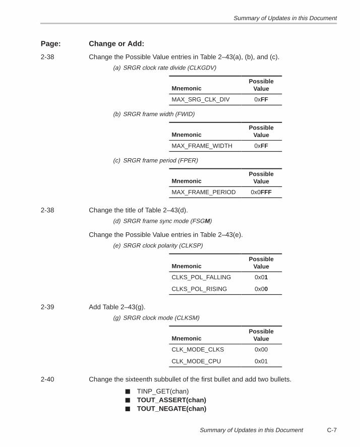
Summary of Updates in this Document
C-7Summary of Updates in this Document
Page: Change or Add:
2-38 Change the Possible Value entries in Table 2–43(a), (b), and (c).
(a) SRGR clock rate divide (CLKGDV)
MnemonicPossible
Value
MAX_SRG_CLK_DIV 0xFF
(b) SRGR frame width (FWID)
MnemonicPossible
Value
MAX_FRAME_WIDTH 0xFF
(c) SRGR frame period (FPER)
MnemonicPossible
Value
MAX_FRAME_PERIOD 0x0FFF
2-38 Change the title of Table 2–43(d).
(d) SRGR frame sync mode (FSGM)
Change the Possible Value entries in Table 2–43(e).
(e) SRGR clock polarity (CLKSP)
MnemonicPossible
Value
CLKS_POL_FALLING 0x01
CLKS_POL_RISING 0x00
2-39 Add Table 2–43(g).
(g) SRGR clock mode (CLKSM)
MnemonicPossible
Value
CLK_MODE_CLKS 0x00
CLK_MODE_CPU 0x01
2-40 Change the sixteenth subbullet of the first bullet and add two bullets.
� TINP_GET(chan)� TOUT_ASSERT(chan)� TOUT_NEGATE(chan)
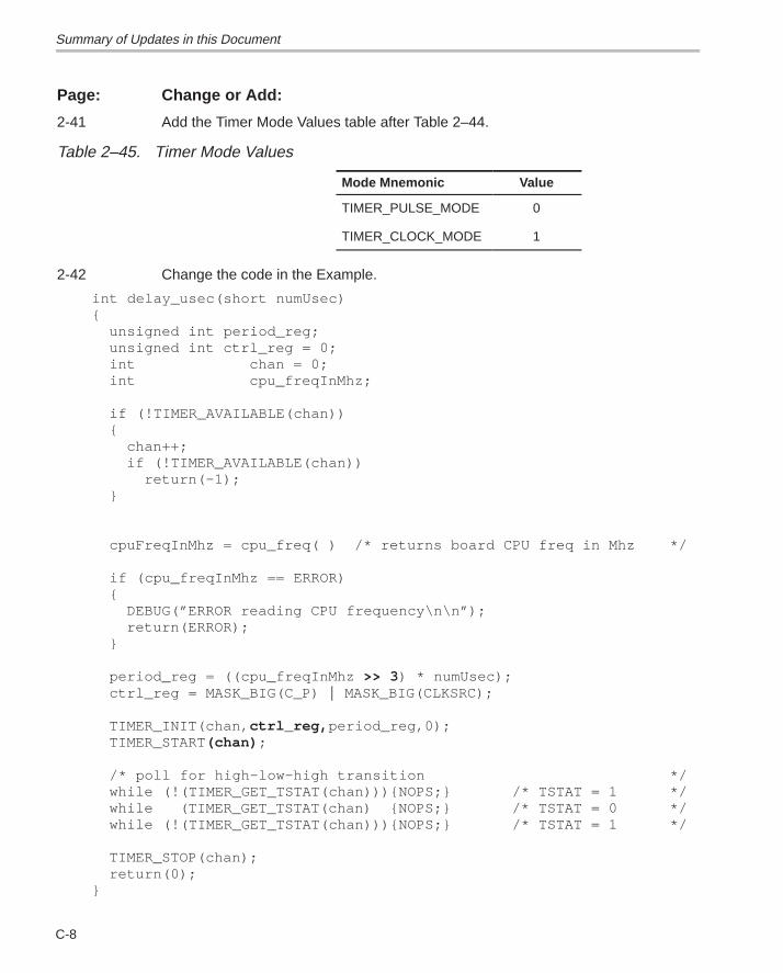
Summary of Updates in this Document
C-8
Page: Change or Add:
2-41 Add the Timer Mode Values table after Table 2–44.
Table 2–45. Timer Mode Values
Mode Mnemonic Value
TIMER_PULSE_MODE 0
TIMER_CLOCK_MODE 1
2-42 Change the code in the Example.
int delay_usec(short numUsec){
unsigned int period_reg;unsigned int ctrl_reg = 0;int chan = 0;int cpu_freqInMhz;
if (!TIMER_AVAILABLE(chan)){
chan++;if (!TIMER_AVAILABLE(chan))
return(–1);}
cpuFreqInMhz = cpu_freq( ) /* returns board CPU freq in Mhz */
if (cpu_freqInMhz == ERROR){
DEBUG(”ERROR reading CPU frequency\n\n”);return(ERROR);
}
period_reg = ((cpu_freqInMhz >> 3 ) * numUsec);ctrl_reg = MASK_BIG(C_P) � MASK_BIG(CLKSRC);
TIMER_INIT(chan, ctrl_reg, period_reg,0);TIMER_START(chan) ;
/* poll for high–low–high transition */while (!(TIMER_GET_TSTAT(chan))){NOPS;} /* TSTAT = 1 */while (TIMER_GET_TSTAT(chan) {NOPS;} /* TSTAT = 0 */while (!(TIMER_GET_TSTAT(chan))){NOPS;} /* TSTAT = 1 */
TIMER_STOP(chan);return(0);
}
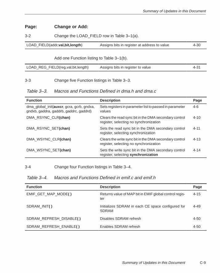
Summary of Updates in this Document
C-9Summary of Updates in this Document
Page: Change or Add:
3-2 Change the LOAD_FIELD row in Table 3–1(a).
LOAD_FIELD(addr,val,bit,length ) Assigns bits in register at address to value 4-30
Add one Function listing to Table 3–1(b).
LOAD_REG_FIELD(reg,val,bit,length) Assigns bits in register to value 4-31
3-3 Change five Function listings in Table 3–3.
Table 3–3. Macros and Functions Defined in dma.h and dma.c
Function Description Page
dma_global_init(auxcr , gcra, gcrb, gndxa,gndxb, gaddra, gaddrb, gaddrc, gaddrd)
Sets registers in parameter list to passed in parametervalues
4-6
DMA_RSYNC_CLR(chan) Clears the read sync bit in the DMA secondary controlregister, selecting no synchronization
4-10
DMA_RSYNC_SET(chan) Sets the read sync bit in the DMA secondary controlregister, selecting synchronization
4-11
DMA_WSYNC_CLR(chan) Clears the write sync bit in the DMA secondary controlregister, selecting no synchronization
4-13
DMA_WSYNC_SET(chan) Sets the write sync bit in the DMA secondary controlregister, selecting synchronization
4-14
3-4 Change four Function listings in Table 3–4.
Table 3–4. Macros and Functions Defined in emif.c and emif.h
Function Description Page
EMIF_GET_MAP_MODE( ) Returns value of MAP bit in EMIF global control regis-ter
4-15
SDRAM_INIT( ) Initializes SDRAM in each CE space configured forSDRAM
4-49
SDRAM_REFRESH_DISABLE( ) Disables SDRAM refresh 4-50
SDRAM_REFRESH_ENABLE( ) Enables SDRAM refresh 4-50
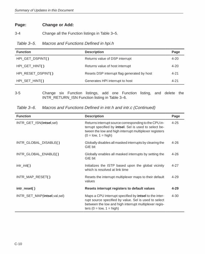
Summary of Updates in this Document
C-10
Page: Change or Add:
3-4 Change all the Function listings in Table 3–5.
Table 3–5. Macros and Functions Defined in hpi.h
Function Description Page
HPI_GET_DSPINT( ) Returns value of DSP interrupt 4-20
HPI_GET_HINT( ) Returns value of host interrupt 4-20
HPI_RESET_DSPINT( ) Resets DSP interrupt flag generated by host 4-21
HPI_SET_HINT( ) Generates HPI interrupt to host 4-21
3-5 Change six Function listings, add one Function listing, and delete theINTR_RETURN_ISN Function listing in Table 3–6.
Table 3–6. Macros and Functions Defined in intr.h and intr.c (Continued)
Function Description Page
INTR_GET_ISN(intsel ,sel) Returns interrupt source corresponding to the CPU in-terrupt specified by intsel . Sel is used to select be-tween the low and high interrupt multiplexer registers(0 = low, 1 = high)
4-25
INTR_GLOBAL_DISABLE( ) Globally disables all masked interrupts by clearing theGIE bit
4-26
INTR_GLOBAL_ENABLE( ) Globally enables all masked interrupts by setting theGIE bit
4-26
intr_init( ) Initializes the ISTP based upon the global vicinitywhich is resolved at link time
4-27
INTR_MAP_RESET( ) Resets the interrupt multiplexer maps to their defaultvalues
4-29
intr_reset( ) Resets interrupt registers to default values 4-29
INTR_SET_MAP(intsel ,val,sel) Maps a CPU interrupt specified by intsel to the inter-rupt source specified by value. Sel is used to selectbetween the low and high interrupt multiplexer regis-ters (0 = low, 1 = high)
4-30
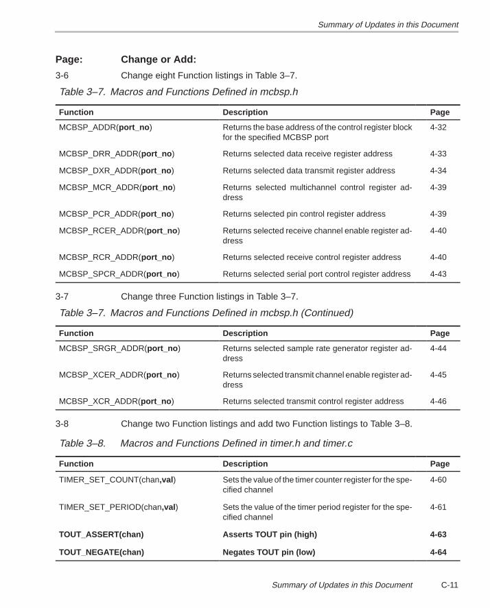
Summary of Updates in this Document
C-11Summary of Updates in this Document
Page: Change or Add:
3-6 Change eight Function listings in Table 3–7.
Table 3–7. Macros and Functions Defined in mcbsp.h
Function Description Page
MCBSP_ADDR(port_no ) Returns the base address of the control register blockfor the specified MCBSP port
4-32
MCBSP_DRR_ADDR(port_no ) Returns selected data receive register address 4-33
MCBSP_DXR_ADDR(port_no ) Returns selected data transmit register address 4-34
MCBSP_MCR_ADDR(port_no ) Returns selected multichannel control register ad-dress
4-39
MCBSP_PCR_ADDR(port_no ) Returns selected pin control register address 4-39
MCBSP_RCER_ADDR(port_no ) Returns selected receive channel enable register ad-dress
4-40
MCBSP_RCR_ADDR(port_no ) Returns selected receive control register address 4-40
MCBSP_SPCR_ADDR(port_no ) Returns selected serial port control register address 4-43
3-7 Change three Function listings in Table 3–7.
Table 3–7. Macros and Functions Defined in mcbsp.h (Continued)
Function Description Page
MCBSP_SRGR_ADDR(port_no ) Returns selected sample rate generator register ad-dress
4-44
MCBSP_XCER_ADDR(port_no ) Returns selected transmit channel enable register ad-dress
4-45
MCBSP_XCR_ADDR(port_no ) Returns selected transmit control register address 4-46
3-8 Change two Function listings and add two Function listings to Table 3–8.
Table 3–8. Macros and Functions Defined in timer.h and timer.c
Function Description Page
TIMER_SET_COUNT(chan,val ) Sets the value of the timer counter register for the spe-cified channel
4-60
TIMER_SET_PERIOD(chan,val ) Sets the value of the timer period register for the spe-cified channel
4-61
TOUT_ASSERT(chan) Asserts TOUT pin (high) 4-63
TOUT_NEGATE(chan) Negates TOUT pin (low) 4-64
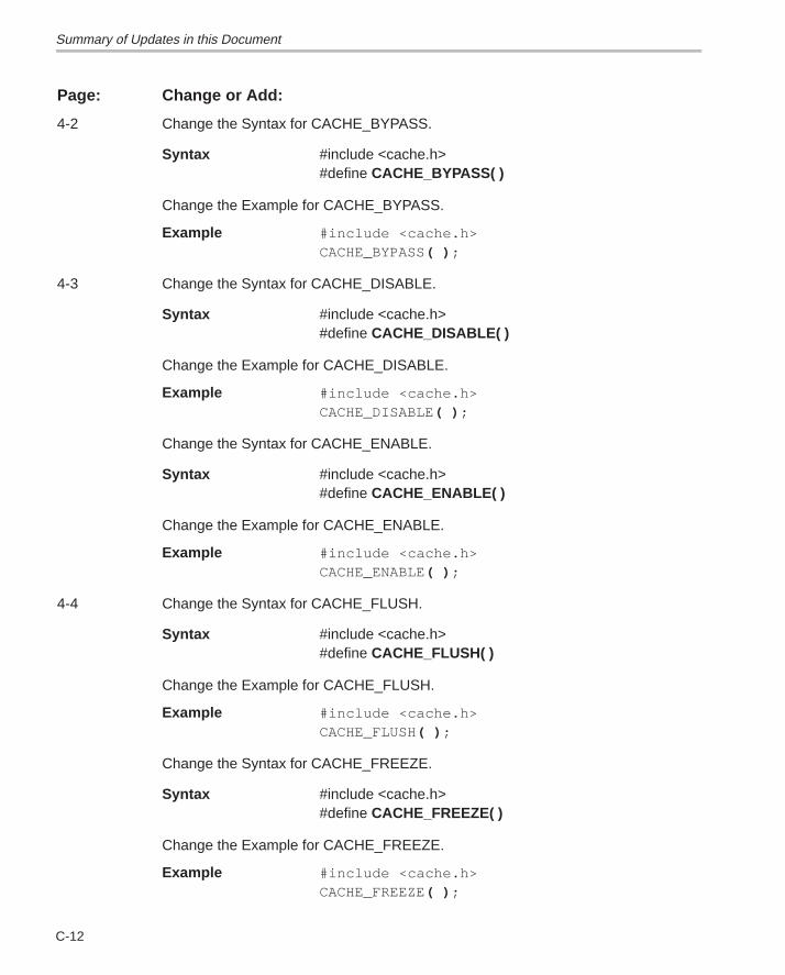
Summary of Updates in this Document
C-12
Page: Change or Add:
4-2 Change the Syntax for CACHE_BYPASS.
Syntax #include <cache.h>#define CACHE_BYPASS( )
Change the Example for CACHE_BYPASS.
Example #include <cache.h>CACHE_BYPASS( ) ;
4-3 Change the Syntax for CACHE_DISABLE.
Syntax #include <cache.h>#define CACHE_DISABLE( )
Change the Example for CACHE_DISABLE.
Example #include <cache.h>CACHE_DISABLE( ) ;
Change the Syntax for CACHE_ENABLE.
Syntax #include <cache.h>#define CACHE_ENABLE( )
Change the Example for CACHE_ENABLE.
Example #include <cache.h>CACHE_ENABLE( ) ;
4-4 Change the Syntax for CACHE_FLUSH.
Syntax #include <cache.h>#define CACHE_FLUSH( )
Change the Example for CACHE_FLUSH.
Example #include <cache.h>CACHE_FLUSH( ) ;
Change the Syntax for CACHE_FREEZE.
Syntax #include <cache.h>#define CACHE_FREEZE( )
Change the Example for CACHE_FREEZE.
Example #include <cache.h>CACHE_FREEZE( ) ;
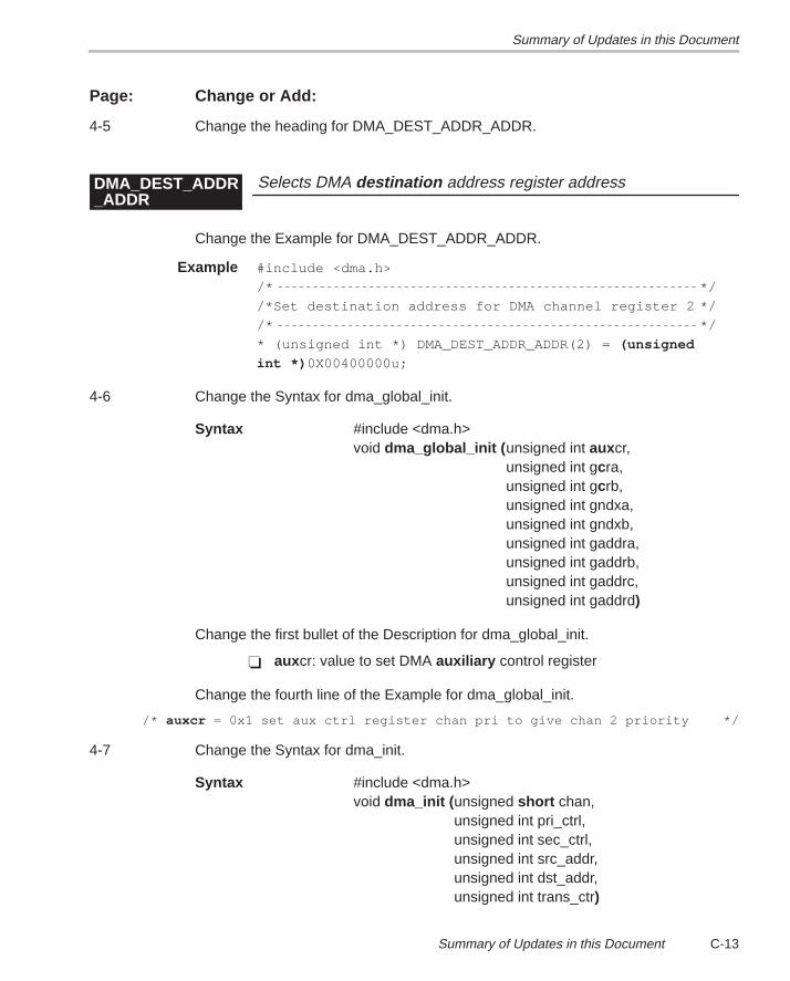
Summary of Updates in this Document
C-13Summary of Updates in this Document
Page: Change or Add:
4-5 Change the heading for DMA_DEST_ADDR_ADDR.
Selects DMA destination address register addressDMA_DEST_ADDR_ADDR
Change the Example for DMA_DEST_ADDR_ADDR.
Example #include <dma.h>
/* */
/*Set destination address for DMA channel register 2 */
/* */
* (unsigned int *) DMA_DEST_ADDR_ADDR(2) = (unsigned
int *) 0X00400000u;
4-6 Change the Syntax for dma_global_init.
Syntax #include <dma.h>void dma_global_init (unsigned int auxcr,
unsigned int gcra,unsigned int gcrb,unsigned int gndxa,unsigned int gndxb,unsigned int gaddra,unsigned int gaddrb,unsigned int gaddrc,unsigned int gaddrd)
Change the first bullet of the Description for dma_global_init.
� auxcr: value to set DMA auxiliary control register
Change the fourth line of the Example for dma_global_init.
/* auxcr = 0x1 set aux ctrl register chan pri to give chan 2 priority */
4-7 Change the Syntax for dma_init.
Syntax #include <dma.h>void dma_init (unsigned short chan,
unsigned int pri_ctrl,unsigned int sec_ctrl,unsigned int src_addr,unsigned int dst_addr,unsigned int trans_ctr)
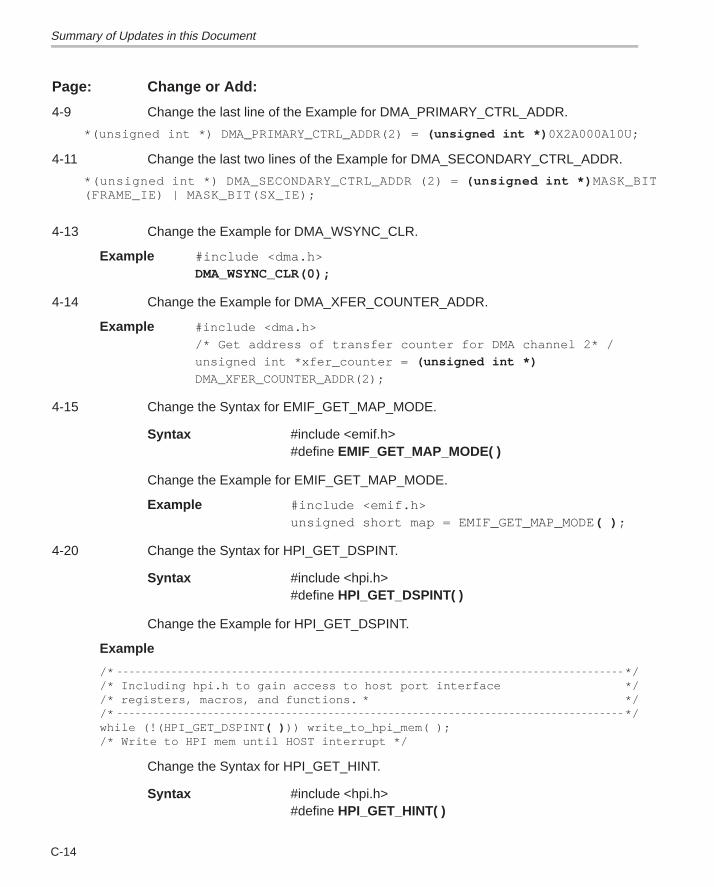
Summary of Updates in this Document
C-14
Page: Change or Add:
4-9 Change the last line of the Example for DMA_PRIMARY_CTRL_ADDR.
*(unsigned int *) DMA_PRIMARY_CTRL_ADDR(2) = (unsigned int *) 0X2A000A10U;
4-11 Change the last two lines of the Example for DMA_SECONDARY_CTRL_ADDR.
*(unsigned int *) DMA_SECONDARY_CTRL_ADDR (2) = (unsigned int *) MASK_BIT(FRAME_IE) | MASK_BIT(SX_IE);
4-13 Change the Example for DMA_WSYNC_CLR.
Example #include <dma.h>DMA_WSYNC_CLR(0);
4-14 Change the Example for DMA_XFER_COUNTER_ADDR.
Example #include <dma.h>
/* Get address of transfer counter for DMA channel 2* /
unsigned int *xfer_counter = (unsigned int *)
DMA_XFER_COUNTER_ADDR(2);
4-15 Change the Syntax for EMIF_GET_MAP_MODE.
Syntax #include <emif.h>#define EMIF_GET_MAP_MODE( )
Change the Example for EMIF_GET_MAP_MODE.
Example #include <emif.h> unsigned short map = EMIF_GET_MAP_MODE ( ) ;
4-20 Change the Syntax for HPI_GET_DSPINT.
Syntax #include <hpi.h>#define HPI_GET_DSPINT( )
Change the Example for HPI_GET_DSPINT.
Example
/* *//* Including hpi.h to gain access to host port interface *//* registers, macros, and functions. * *//* */while (!(HPI_GET_DSPINT ( ) )) write_to_hpi_mem( );/* Write to HPI mem until HOST interrupt */
Change the Syntax for HPI_GET_HINT.
Syntax #include <hpi.h>#define HPI_GET_HINT( )
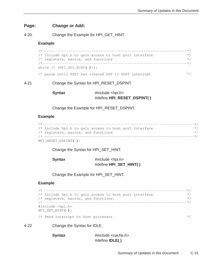
Summary of Updates in this Document
C-15Summary of Updates in this Document
Page: Change or Add:
4-20 Change the Example for HPI_GET_HINT.
Example
/* *//* Include hpi.h to gain access to host port interface *//* registers, macros, and functions *//* */while (! (HPI_GET_HINT ( ) ));
/* pause until HOST has cleared DSP to HOST interrupt */
4-21 Change the Syntax for HPI_RESET_DSPINT.
Syntax #include <hpi.h>#define HPI_RESET_DSPINT( )
Change the Example for HPI_RESET_DSPINT.
Example
/* *//* Include hpi.h to gain access to host port interface *//* registers, macros, and functions *//* */HPI_RESET_DSPINT( ) ;
Change the Syntax for HPI_SET_HINT.
Syntax #include <hpi.h>#define HPI_SET_HINT( )
Change the Example for HPI_SET_HINT.
Example
/* *//* Include hpi.h to gain access to host port interface *//* registers, macros, and functions. *//* */#include <hpi.h>HPI_SET_HINT ( ) ;
/* Send interrupt to host processor */
4-22 Change the Syntax for IDLE.
Syntax #include <cache.h>#define IDLE( )
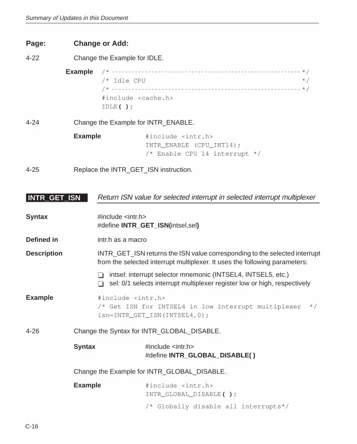
Summary of Updates in this Document
C-16
Page: Change or Add:
4-22 Change the Example for IDLE.
Example /* *//* Idle CPU *//* */#include <cache.h>IDLE ( ) ;
4-24 Change the Example for INTR_ENABLE.
Example #include <intr.h>INTR_ENABLE (CPU_INT14);/* Enable CPU 14 interrupt */
4-25 Replace the INTR_GET_ISN instruction.
Return ISN value for selected interrupt in selected interrupt multiplexerINTR_GET_ISN
Syntax #include <intr.h>#define INTR_GET_ISN(intsel,sel)
Defined in intr.h as a macro
Description INTR_GET_ISN returns the ISN value corresponding to the selected interruptfrom the selected interrupt multiplexer. It uses the following parameters:
� intsel: interrupt selector mnemonic (INTSEL4, INTSEL5, etc.)� sel: 0/1 selects interrupt multiplexer register low or high, respectively
Example #include <intr.h> /* Get ISN for INTSEL4 in low interrupt multiplexer */isn=INTR_GET_ISN(INTSEL4,0);
4-26 Change the Syntax for INTR_GLOBAL_DISABLE.
Syntax #include <intr.h>#define INTR_GLOBAL_DISABLE( )
Change the Example for INTR_GLOBAL_DISABLE.
Example #include <intr.h>INTR_GLOBAL_DISABLE( ) ;
/* Globally disable all interrupts*/
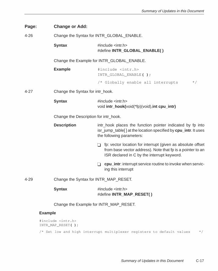
Summary of Updates in this Document
C-17Summary of Updates in this Document
Page: Change or Add:
4-26 Change the Syntax for INTR_GLOBAL_ENABLE.
Syntax #include <intr.h>#define INTR_GLOBAL_ENABLE( )
Change the Example for INTR_GLOBAL_ENABLE.
Example #include <intr.h>INTR_GLOBAL_ENABLE( ) ;
/* Globally enable all interrupts */
4-27 Change the Syntax for intr_hook.
Syntax #include <intr.h>void intr_hook( void(*fp)(void),int cpu_intr)
Change the Description for intr_hook.
Description intr_hook places the function pointer indicated by fp intoisr_jump_table[ ] at the location specified by cpu_intr . It usesthe following parameters:
� fp: vector location for interrupt (given as absolute offsetfrom base vector address). Note that fp is a pointer to anISR declared in C by the interrupt keyword.
� cpu_intr : interrupt service routine to invoke when servic-ing this interrupt
4-29 Change the Syntax for INTR_MAP_RESET.
Syntax #include <intr.h>#define INTR_MAP_RESET( )
Change the Example for INTR_MAP_RESET.
Example
#include <intr.h>INTR_MAP_RESET( ) ;
/* Set low and high interrupt multiplexer registers to default values */
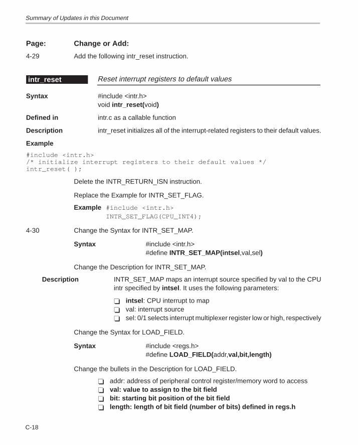
Summary of Updates in this Document
C-18
Page: Change or Add:
4-29 Add the following intr_reset instruction.
Reset interrupt registers to default valuesintr_reset
Syntax #include <intr.h>void intr_reset( void)
Defined in intr.c as a callable function
Description intr_reset initializes all of the interrupt-related registers to their default values.
Example
#include <intr.h>/* initialize interrupt registers to their default values */intr_reset( );
Delete the INTR_RETURN_ISN instruction.
Replace the Example for INTR_SET_FLAG.
Example #include <intr.h>INTR_SET_FLAG(CPU_INT4);
4-30 Change the Syntax for INTR_SET_MAP.
Syntax #include <intr.h>#define INTR_SET_MAP(intsel ,val,sel)
Change the Description for INTR_SET_MAP.
Description INTR_SET_MAP maps an interrupt source specified by val to the CPUintr specified by intsel . It uses the following parameters:
� intsel : CPU interrupt to map� val: interrupt source� sel: 0/1 selects interrupt multiplexer register low or high, respectively
Change the Syntax for LOAD_FIELD.
Syntax #include <regs.h>#define LOAD_FIELD( addr,val,bit,length)
Change the bullets in the Description for LOAD_FIELD.
� addr: address of peripheral control register/memory word to access� val: value to assign to the bit field� bit: starting bit position of the bit field� length: length of bit field (number of bits) defined in regs.h
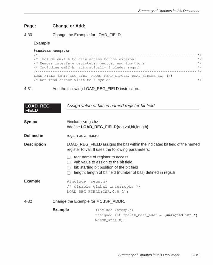
Summary of Updates in this Document
C-19Summary of Updates in this Document
Page: Change or Add:
4-30 Change the Example for LOAD_FIELD.
Example
#include <regs.h>/* *//* Include emif.h to gain access to the external *//* Memory interface registers, macros, and functions *//* Including emif.h, automatically includes regs.h *//* */LOAD_FIELD (EMIF_CEO_CTRL__ADDR, READ_STROBE, READ_STROBE_SZ, 4); /* Set read strobe width to 4 cycles */
4-31 Add the following LOAD_REG_FIELD instruction.
Assign value of bits in named register bit fieldLOAD_REG_FIELD
Syntax #include <regs.h>#define LOAD_REG_FIELD( reg,val,bit,length)
Defined in regs.h as a macro
Description LOAD_REG_FIELD assigns the bits within the indicated bit field of the namedregister to val. It uses the following parameters:
� reg: name of register to access� val: value to assign to the bit field� bit: starting bit position of the bit field� length: length of bit field (number of bits) defined in regs.h
Example #include <regs.h>/* disable global interrupts */LOAD_REG_FIELD(CSR,0,0,2);
4-32 Change the Example for MCBSP_ADDR.
Example #include <mcbsp.h>
unsigned int *port0_base_addr = (unsigned int *)
MCBSP_ADDR(0);
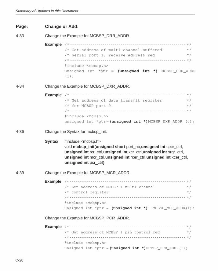
Summary of Updates in this Document
C-20
Page: Change or Add:
4-33 Change the Example for MCBSP_DRR_ADDR.
Example /* *//* Get address of multi channel buffered *//* serial port 1, receive address reg *//* */#include <mcbsp.h>unsigned int *ptr = (unsigned int *) MCBSP_DRR_ADDR(1);
4-34 Change the Example for MCBSP_DXR_ADDR.
Example /* *//* Get address of data transmit register *//* for MCBSP port 0. *//* */#include <mcbsp.h>unsigned int *ptr= (unsigned int *) MCBSP_DXR_ADDR (0);
4-36 Change the Syntax for mcbsp_init.
Syntax #include <mcbsp.h>void mcbsp_init(unsigned short port_no,unsigned int spcr_ctrl,unsigned int rcr_ctrl,unsigned int xcr_ctrl,unsigned int srgr_ctrl,unsigned int mcr_ctrl,unsigned int rcer_ctrl,unsigned int xcer_ctrl,unsigned int pcr_ctrl)
4-39 Change the Example for MCBSP_MCR_ADDR.
Example /* */
/* Get address of MCBSP 1 multi–channel */
/* control register */
/* */
#include <mcbsp.h>
unsigned int *ptr = (unsigned int *) MCBSP_MCR_ADDR(1);
Change the Example for MCBSP_PCR_ADDR.
Example /* */
/* Get address of MCBSP 1 pin control reg */
/* */
#include <mcbsp.h>
unsigned int *ptr = (unsigned int *) MCBSP_PCR_ADDR(1);
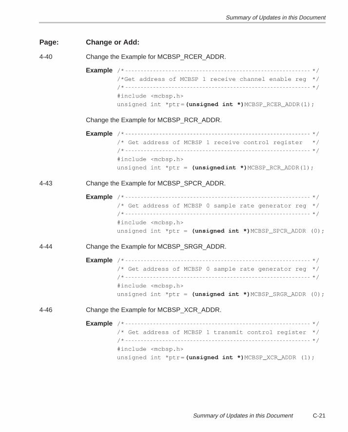
Summary of Updates in this Document
C-21Summary of Updates in this Document
Page: Change or Add:
4-40 Change the Example for MCBSP_RCER_ADDR.
Example /* */
/*Get address of MCBSP 1 receive channel enable reg */
/* */
#include <mcbsp.h>
unsigned int *ptr= (unsigned int *) MCBSP_RCER_ADDR(1);
Change the Example for MCBSP_RCR_ADDR.
Example /* */
/* Get address of MCBSP 1 receive control register */
/* */
#include <mcbsp.h>
unsigned int *ptr = (unsigned int *) MCBSP_RCR_ADDR(1);
4-43 Change the Example for MCBSP_SPCR_ADDR.
Example /* */
/* Get address of MCBSP 0 sample rate generator reg */
/* */
#include <mcbsp.h>
unsigned int *ptr = (unsigned int *) MCBSP_SPCR_ADDR (0);
4-44 Change the Example for MCBSP_SRGR_ADDR.
Example /* */
/* Get address of MCBSP 0 sample rate generator reg */
/* */
#include <mcbsp.h>
unsigned int *ptr = (unsigned int *) MCBSP_SRGR_ADDR (0);
4-46 Change the Example for MCBSP_XCR_ADDR.
Example /* */
/* Get address of MCBSP 1 transmit control register */
/* */
#include <mcbsp.h>
unsigned int *ptr= (unsigned int *) MCBSP_XCR_ADDR (1);
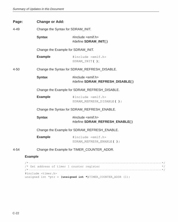
Summary of Updates in this Document
C-22
Page: Change or Add:
4-49 Change the Syntax for SDRAM_INIT.
Syntax #include <emif.h>#define SDRAM_INIT( )
Change the Example for SDRAM_INIT.
Example #include <emif.h> SDRAM_INIT( ) ;
4-50 Change the Syntax for SDRAM_REFRESH_DISABLE.
Syntax #include <emif.h>#define SDRAM_REFRESH_DISABLE( )
Change the Example for SDRAM_REFRESH_DISABLE.
Example #include <emif.h>SDRAM_REFRESH_DISABLE( ) ;
Change the Syntax for SDRAM_REFRESH_ENABLE.
Syntax #include <emif.h>#define SDRAM_REFRESH_ENABLE( )
Change the Example for SDRAM_REFRESH_ENABLE.
Example #include <emif.h> SDRAM_REFRESH_ENABLE( ) ;
4-54 Change the Example for TIMER_COUNTER_ADDR.
Example
/* *//* Get address of timer 1 counter register *//* */#include <timer.h>unsigned int *ptr = (unsigned int *) TIMER_COUNTER_ADDR (1);
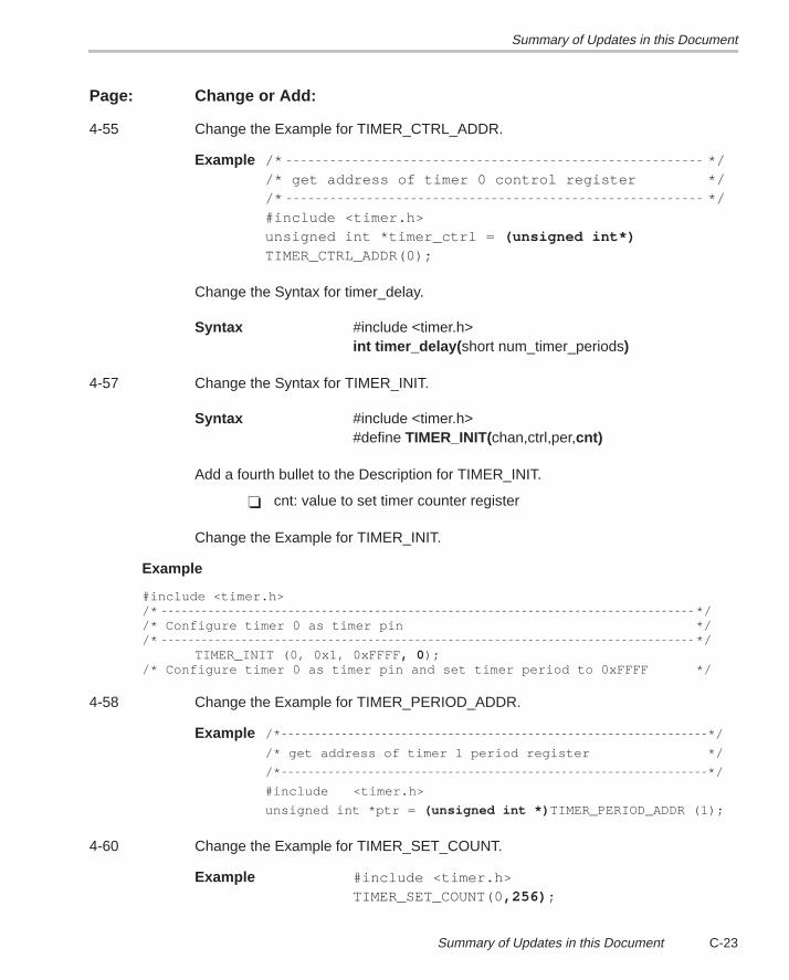
Summary of Updates in this Document
C-23Summary of Updates in this Document
Page: Change or Add:
4-55 Change the Example for TIMER_CTRL_ADDR.
Example /* *//* get address of timer 0 control register *//* */#include <timer.h>unsigned int *timer_ctrl = (unsigned int*)TIMER_CTRL_ADDR(0);
Change the Syntax for timer_delay.
Syntax #include <timer.h>int timer_delay( short num_timer_periods)
4-57 Change the Syntax for TIMER_INIT.
Syntax #include <timer.h>#define TIMER_INIT(chan,ctrl,per,cnt)
Add a fourth bullet to the Description for TIMER_INIT.
� cnt: value to set timer counter register
Change the Example for TIMER_INIT.
Example
#include <timer.h>/* *//* Configure timer 0 as timer pin *//* */
TIMER_INIT (0, 0x1, 0xFFFF , 0 );/* Configure timer 0 as timer pin and set timer period to 0xFFFF */
4-58 Change the Example for TIMER_PERIOD_ADDR.
Example /* */
/* get address of timer 1 period register */
/* */
#include <timer.h>
unsigned int *ptr = (unsigned int *) TIMER_PERIOD_ADDR (1);
4-60 Change the Example for TIMER_SET_COUNT.
Example #include <timer.h>TIMER_SET_COUNT(0,256) ;
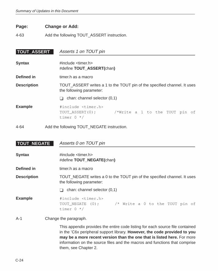
Summary of Updates in this Document
C-24
Page: Change or Add:
4-63 Add the following TOUT_ASSERT instruction.
Asserts 1 on TOUT pinTOUT_ASSERT
Syntax #include <timer.h>#define TOUT_ASSERT(chan)
Defined in timer.h as a macro
Description TOUT_ASSERT writes a 1 to the TOUT pin of the specified channel. It usesthe following parameter:
� chan: channel selector (0,1)
Example #include <timer.h>TOUT_ASSERT(0); /*Write a 1 to the TOUT pin oftimer 0 */
4-64 Add the following TOUT_NEGATE instruction.
Asserts 0 on TOUT pinTOUT_NEGATE
Syntax #include <timer.h>#define TOUT_NEGATE(chan)
Defined in timer.h as a macro
Description TOUT_NEGATE writes a 0 to the TOUT pin of the specified channel. It usesthe following parameter:
� chan: channel selector (0,1)
Example #include <timer.h>TOUT_NEGATE (0); /* Write a 0 to the TOUT pin oftimer 0 */
A-1 Change the paragraph.
This appendix provides the entire code listing for each source file containedin the ’C6x peripheral support library. However, the code provided to youmay be a more recent version than the one that is listed here. For moreinformation on the source files and the macros and functions that comprisethem, see Chapter 2.
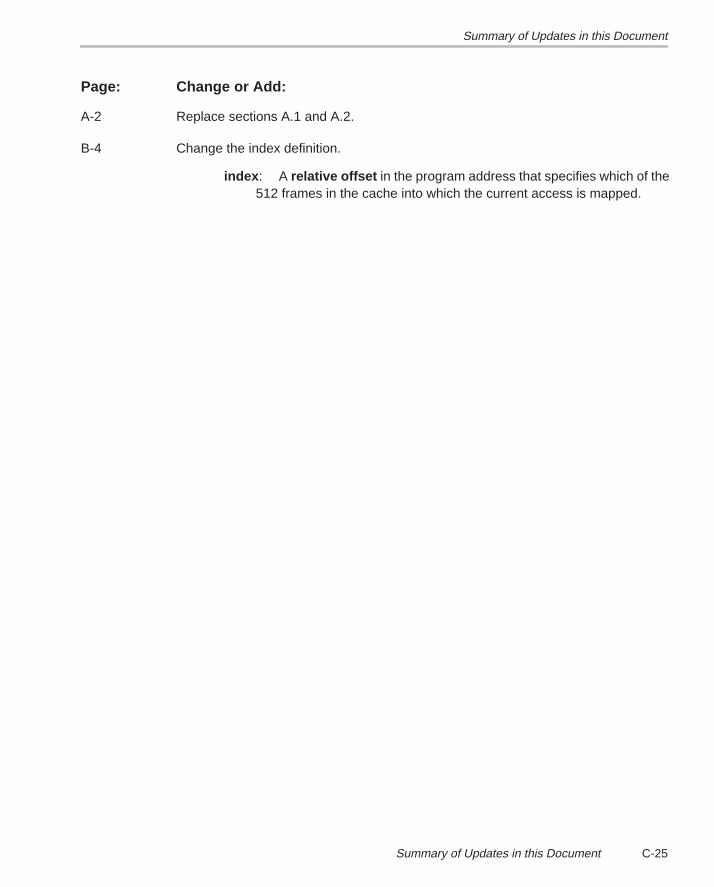
Summary of Updates in this Document
C-25Summary of Updates in this Document
Page: Change or Add:
A-2 Replace sections A.1 and A.2.
B-4 Change the index definition.
index : A relative offset in the program address that specifies which of the512 frames in the cache into which the current access is mapped.
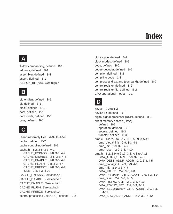
Index
Index-1
Index
AA–law companding, defined B-1address, defined B-1
assembler, defined B-1
assert, defined B-1
ASSIGN_BIT_VAL. See regs.h
Bbig endian, defined B-1
bit, defined B-1block, defined B-1
boot, defined B-1
boot mode, defined B-1
byte, defined B-1
CC and assembly files A-39 to A-59
cache, defined B-2cache controller, defined B-2
cache.h 1-2, 2-8, 3-3, A-2CACHE_BYPASS 2-8, 3-3, 4-2CACHE_DISABLE 2-8, 3-3, 4-3CACHE_ENABLE 2-8, 3-3, 4-3CACHE_FLUSH 2-8, 3-3, 4-4CACHE_FREEZE 2-8, 3-3, 4-4IDLE 2-8, 3-3, 4-22
CACHE_BYPASS. See cache.h
CACHE_DISABLE. See cache.h
CACHE_ENABLE. See cache.h
CACHE_FLUSH. See cache.hCACHE_FREEZE. See cache.h
central processing unit (CPU), defined B-2
clock cycle, defined B-2clock modes, defined B-2code, defined B-2coder–decoder, defined B-2compiler, defined B-2compiling code 1-3compress and expand (compand), defined B-2control register, defined B-2control register file, defined B-2CPU operational modes 1-1
Ddev6x 1-2 to 1-3device ID, defined B-3digital signal processor (DSP), defined B-3direct memory access (DMA)
defined B-3operation, defined B-3source, defined B-3transfer, defined B-3
dma.c 1-2, 2-9 to 2-17, 3-3, A-39 to A-41dma_global_init 2-9, 3-3, 4-6dma_init 2-9, 3-3, 4-7dma_reset 2-9, 3-3, 4-10
dma.h 1-2, 2-9 to 2-17, 3-3, A-3 to A-11DMA_AUTO_START 2-9, 3-3, 4-5DMA_DEST_ADDR_ADDR 2-9, 3-3, 4-5dma_global_init 2-9, 3-3, 4-6dma_init 2-9, 3-3, 4-7DMA_PAUSE 2-9, 3-3, 4-8DMA_PRIMARY_CTRL_ADDR 2-9, 3-3, 4-9dma_reset 2-9, 3-3, 4-10DMA_RSYNC_CLR 2-9, 3-3, 4-10DMA_RSYNC_SET 2-9, 3-3, 4-11DMA_SECONDARY_CTRL_ADDR 2-9, 3-3,
4-11DMA_SRC_ADDR_ADDR 2-9, 3-3, 4-12
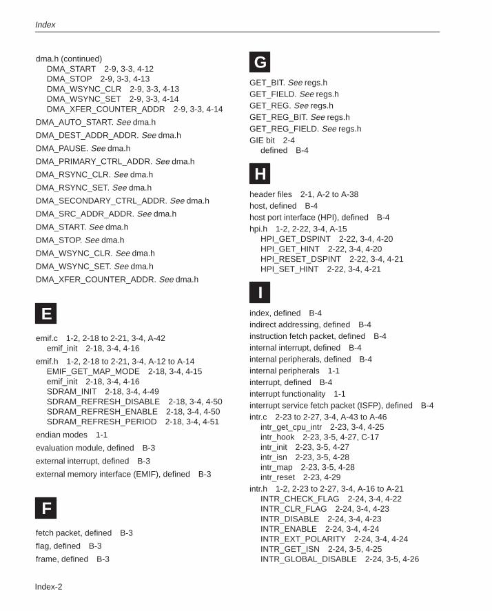
Index
Index-2
dma.h (continued)DMA_START 2-9, 3-3, 4-12DMA_STOP 2-9, 3-3, 4-13DMA_WSYNC_CLR 2-9, 3-3, 4-13DMA_WSYNC_SET 2-9, 3-3, 4-14DMA_XFER_COUNTER_ADDR 2-9, 3-3, 4-14
DMA_AUTO_START. See dma.h
DMA_DEST_ADDR_ADDR. See dma.h
DMA_PAUSE. See dma.h
DMA_PRIMARY_CTRL_ADDR. See dma.h
DMA_RSYNC_CLR. See dma.h
DMA_RSYNC_SET. See dma.h
DMA_SECONDARY_CTRL_ADDR. See dma.h
DMA_SRC_ADDR_ADDR. See dma.h
DMA_START. See dma.h
DMA_STOP. See dma.h
DMA_WSYNC_CLR. See dma.h
DMA_WSYNC_SET. See dma.h
DMA_XFER_COUNTER_ADDR. See dma.h
Eemif.c 1-2, 2-18 to 2-21, 3-4, A-42
emif_init 2-18, 3-4, 4-16
emif.h 1-2, 2-18 to 2-21, 3-4, A-12 to A-14EMIF_GET_MAP_MODE 2-18, 3-4, 4-15emif_init 2-18, 3-4, 4-16SDRAM_INIT 2-18, 3-4, 4-49SDRAM_REFRESH_DISABLE 2-18, 3-4, 4-50SDRAM_REFRESH_ENABLE 2-18, 3-4, 4-50SDRAM_REFRESH_PERIOD 2-18, 3-4, 4-51
endian modes 1-1
evaluation module, defined B-3
external interrupt, defined B-3
external memory interface (EMIF), defined B-3
Ffetch packet, defined B-3
flag, defined B-3
frame, defined B-3
GGET_BIT. See regs.hGET_FIELD. See regs.hGET_REG. See regs.hGET_REG_BIT. See regs.hGET_REG_FIELD. See regs.hGIE bit 2-4
defined B-4
Hheader files 2-1, A-2 to A-38host, defined B-4host port interface (HPI), defined B-4hpi.h 1-2, 2-22, 3-4, A-15
HPI_GET_DSPINT 2-22, 3-4, 4-20HPI_GET_HINT 2-22, 3-4, 4-20HPI_RESET_DSPINT 2-22, 3-4, 4-21HPI_SET_HINT 2-22, 3-4, 4-21
Iindex, defined B-4indirect addressing, defined B-4instruction fetch packet, defined B-4internal interrupt, defined B-4internal peripherals, defined B-4internal peripherals 1-1interrupt, defined B-4interrupt functionality 1-1interrupt service fetch packet (ISFP), defined B-4intr.c 2-23 to 2-27, 3-4, A-43 to A-46
intr_get_cpu_intr 2-23, 3-4, 4-25intr_hook 2-23, 3-5, 4-27, C-17intr_init 2-23, 3-5, 4-27intr_isn 2-23, 3-5, 4-28intr_map 2-23, 3-5, 4-28intr_reset 2-23, 4-29
intr.h 1-2, 2-23 to 2-27, 3-4, A-16 to A-21INTR_CHECK_FLAG 2-24, 3-4, 4-22INTR_CLR_FLAG 2-24, 3-4, 4-23INTR_DISABLE 2-24, 3-4, 4-23INTR_ENABLE 2-24, 3-4, 4-24INTR_EXT_POLARITY 2-24, 3-4, 4-24INTR_GET_ISN 2-24, 3-5, 4-25INTR_GLOBAL_DISABLE 2-24, 3-5, 4-26
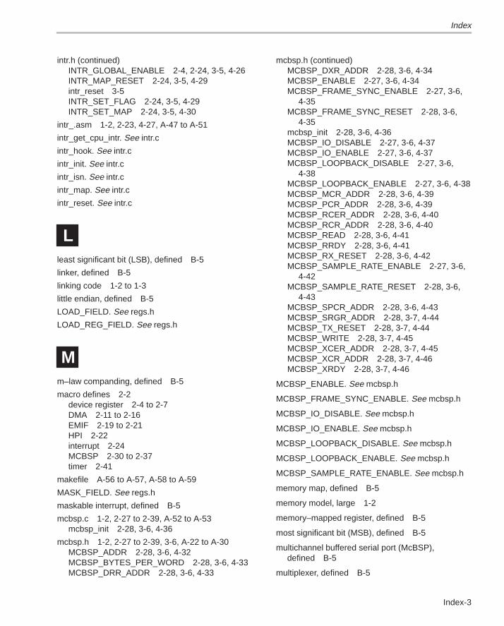
Index
Index-3
intr.h (continued)INTR_GLOBAL_ENABLE 2-4, 2-24, 3-5, 4-26INTR_MAP_RESET 2-24, 3-5, 4-29intr_reset 3-5INTR_SET_FLAG 2-24, 3-5, 4-29INTR_SET_MAP 2-24, 3-5, 4-30
intr_.asm 1-2, 2-23, 4-27, A-47 to A-51
intr_get_cpu_intr. See intr.c
intr_hook. See intr.c
intr_init. See intr.c
intr_isn. See intr.c
intr_map. See intr.c
intr_reset. See intr.c
Lleast significant bit (LSB), defined B-5
linker, defined B-5
linking code 1-2 to 1-3
little endian, defined B-5
LOAD_FIELD. See regs.h
LOAD_REG_FIELD. See regs.h
Mm–law companding, defined B-5
macro defines 2-2device register 2-4 to 2-7DMA 2-11 to 2-16EMIF 2-19 to 2-21HPI 2-22interrupt 2-24MCBSP 2-30 to 2-37timer 2-41
makefile A-56 to A-57, A-58 to A-59
MASK_FIELD. See regs.h
maskable interrupt, defined B-5
mcbsp.c 1-2, 2-27 to 2-39, A-52 to A-53mcbsp_init 2-28, 3-6, 4-36
mcbsp.h 1-2, 2-27 to 2-39, 3-6, A-22 to A-30MCBSP_ADDR 2-28, 3-6, 4-32MCBSP_BYTES_PER_WORD 2-28, 3-6, 4-33MCBSP_DRR_ADDR 2-28, 3-6, 4-33
mcbsp.h (continued)MCBSP_DXR_ADDR 2-28, 3-6, 4-34MCBSP_ENABLE 2-27, 3-6, 4-34MCBSP_FRAME_SYNC_ENABLE 2-27, 3-6,
4-35MCBSP_FRAME_SYNC_RESET 2-28, 3-6,
4-35mcbsp_init 2-28, 3-6, 4-36MCBSP_IO_DISABLE 2-27, 3-6, 4-37MCBSP_IO_ENABLE 2-27, 3-6, 4-37MCBSP_LOOPBACK_DISABLE 2-27, 3-6,
4-38MCBSP_LOOPBACK_ENABLE 2-27, 3-6, 4-38MCBSP_MCR_ADDR 2-28, 3-6, 4-39MCBSP_PCR_ADDR 2-28, 3-6, 4-39MCBSP_RCER_ADDR 2-28, 3-6, 4-40MCBSP_RCR_ADDR 2-28, 3-6, 4-40MCBSP_READ 2-28, 3-6, 4-41MCBSP_RRDY 2-28, 3-6, 4-41MCBSP_RX_RESET 2-28, 3-6, 4-42MCBSP_SAMPLE_RATE_ENABLE 2-27, 3-6,
4-42MCBSP_SAMPLE_RATE_RESET 2-28, 3-6,
4-43MCBSP_SPCR_ADDR 2-28, 3-6, 4-43MCBSP_SRGR_ADDR 2-28, 3-7, 4-44MCBSP_TX_RESET 2-28, 3-7, 4-44MCBSP_WRITE 2-28, 3-7, 4-45MCBSP_XCER_ADDR 2-28, 3-7, 4-45MCBSP_XCR_ADDR 2-28, 3-7, 4-46MCBSP_XRDY 2-28, 3-7, 4-46
MCBSP_ENABLE. See mcbsp.h
MCBSP_FRAME_SYNC_ENABLE. See mcbsp.h
MCBSP_IO_DISABLE. See mcbsp.h
MCBSP_IO_ENABLE. See mcbsp.h
MCBSP_LOOPBACK_DISABLE. See mcbsp.h
MCBSP_LOOPBACK_ENABLE. See mcbsp.h
MCBSP_SAMPLE_RATE_ENABLE. See mcbsp.h
memory map, defined B-5
memory model, large 1-2
memory–mapped register, defined B-5
most significant bit (MSB), defined B-5
multichannel buffered serial port (McBSP),defined B-5
multiplexer, defined B-5
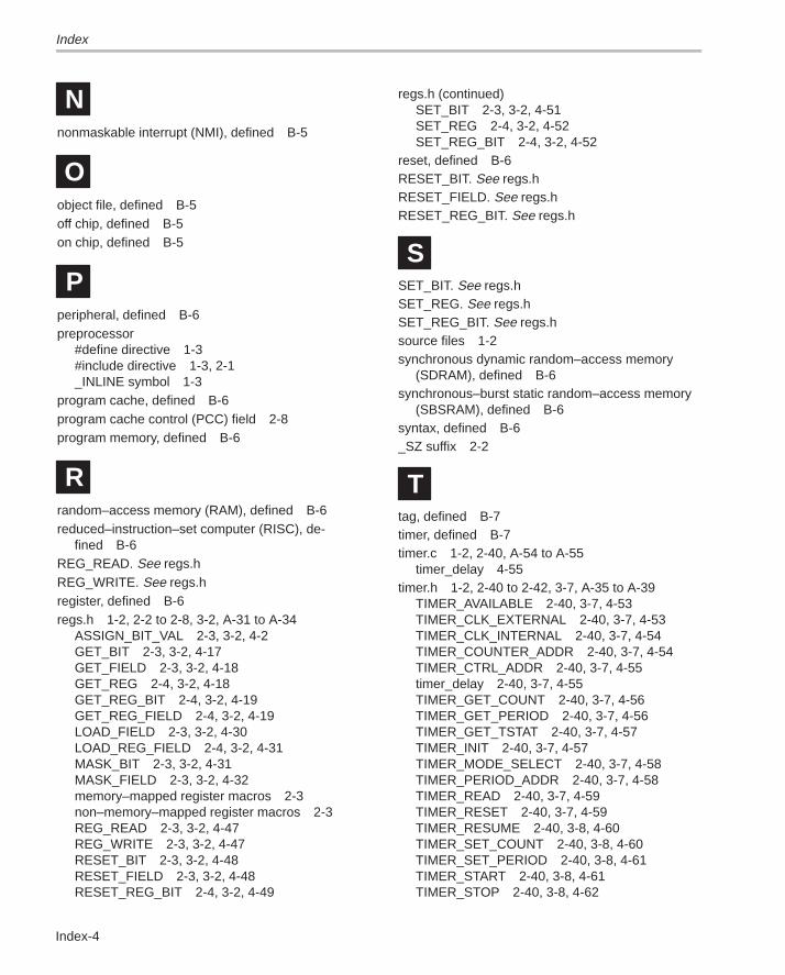
Index
Index-4
Nnonmaskable interrupt (NMI), defined B-5
Oobject file, defined B-5off chip, defined B-5on chip, defined B-5
Pperipheral, defined B-6preprocessor
#define directive 1-3#include directive 1-3, 2-1_INLINE symbol 1-3
program cache, defined B-6program cache control (PCC) field 2-8program memory, defined B-6
Rrandom–access memory (RAM), defined B-6reduced–instruction–set computer (RISC), de-
fined B-6REG_READ. See regs.hREG_WRITE. See regs.hregister, defined B-6regs.h 1-2, 2-2 to 2-8, 3-2, A-31 to A-34
ASSIGN_BIT_VAL 2-3, 3-2, 4-2GET_BIT 2-3, 3-2, 4-17GET_FIELD 2-3, 3-2, 4-18GET_REG 2-4, 3-2, 4-18GET_REG_BIT 2-4, 3-2, 4-19GET_REG_FIELD 2-4, 3-2, 4-19LOAD_FIELD 2-3, 3-2, 4-30LOAD_REG_FIELD 2-4, 3-2, 4-31MASK_BIT 2-3, 3-2, 4-31MASK_FIELD 2-3, 3-2, 4-32memory–mapped register macros 2-3non–memory–mapped register macros 2-3REG_READ 2-3, 3-2, 4-47REG_WRITE 2-3, 3-2, 4-47RESET_BIT 2-3, 3-2, 4-48RESET_FIELD 2-3, 3-2, 4-48RESET_REG_BIT 2-4, 3-2, 4-49
regs.h (continued)SET_BIT 2-3, 3-2, 4-51SET_REG 2-4, 3-2, 4-52SET_REG_BIT 2-4, 3-2, 4-52
reset, defined B-6RESET_BIT. See regs.hRESET_FIELD. See regs.hRESET_REG_BIT. See regs.h
SSET_BIT. See regs.hSET_REG. See regs.hSET_REG_BIT. See regs.hsource files 1-2synchronous dynamic random–access memory
(SDRAM), defined B-6synchronous–burst static random–access memory
(SBSRAM), defined B-6syntax, defined B-6_SZ suffix 2-2
Ttag, defined B-7timer, defined B-7timer.c 1-2, 2-40, A-54 to A-55
timer_delay 4-55timer.h 1-2, 2-40 to 2-42, 3-7, A-35 to A-39
TIMER_AVAILABLE 2-40, 3-7, 4-53TIMER_CLK_EXTERNAL 2-40, 3-7, 4-53TIMER_CLK_INTERNAL 2-40, 3-7, 4-54TIMER_COUNTER_ADDR 2-40, 3-7, 4-54TIMER_CTRL_ADDR 2-40, 3-7, 4-55timer_delay 2-40, 3-7, 4-55TIMER_GET_COUNT 2-40, 3-7, 4-56TIMER_GET_PERIOD 2-40, 3-7, 4-56TIMER_GET_TSTAT 2-40, 3-7, 4-57TIMER_INIT 2-40, 3-7, 4-57TIMER_MODE_SELECT 2-40, 3-7, 4-58TIMER_PERIOD_ADDR 2-40, 3-7, 4-58TIMER_READ 2-40, 3-7, 4-59TIMER_RESET 2-40, 3-7, 4-59TIMER_RESUME 2-40, 3-8, 4-60TIMER_SET_COUNT 2-40, 3-8, 4-60TIMER_SET_PERIOD 2-40, 3-8, 4-61TIMER_START 2-40, 3-8, 4-61TIMER_STOP 2-40, 3-8, 4-62
Index
Index-5
timer.h (continued)TINP_GET 2-40, 3-8, 4-62TOUT_ASSERT 2-40, 3-8, 4-63TOUT_DISABLE 2-40, 3-8, 4-63TOUT_ENABLE 2-40, 3-8, 4-63TOUT_NEGATE 2-40, 3-8, 4-64TOUT_VAL 2-40, 3-8, 4-64
TIMER_AVAILABLE. See timer.h
TIMER_CLK_EXTERNAL. See timer.h
TIMER_CLK_INTERNAL. See timer.h
TIMER_COUNTER_ADDR. See timer.h
TIMER_CTRL_ADDR. See timer.h
TIMER_GET_COUNT. See timer.h
TIMER_GET_PERIOD. See timer.h
TIMER_GET_TSTAT. See timer.h
TIMER_INIT. See timer.h
TIMER_MODE_SELECT. See timer.h
TIMER_PERIOD_ADDR. See timer.hTIMER_RESET. See timer.hTIMER_RESUME. See timer.hTIMER_SET_COUNT. See timer.hTIMER_SET_PERIOD. See timer.hTIMER_START. See timer.hTIMER_STOP. See timer.hTINP_GET. See timer.hTOUT_ASSERT. See timer.hTOUT_DISABLE. See timer.hTOUT_ENABLE. See timer.hTOUT_NEGATE. See timer.hTOUT_VAL. See timer.h
Wword, defined B-7


![Programmer’s GuideC7 Microsoft C 7.0 [.Extensions] Component Here are examples of extensions: Extension Description .LIB A library. Can be a static linked library or an import library](https://img.pdfslide.net/doc/110x75/5f05156e7e708231d4112e24/programmeras-guide-c7-microsoft-c-70-extensions-component-here-are-examples.jpg)