Embed Size (px)
Citation preview

UNCLASSIFIED
AD NUMBER
AD881759
NEW LIMITATION CHANGE
TOApproved for public release, distributionunlimited
FROMDistribution authorized to U.S. Gov't.agencies and their contractors; CriticalTechnology; AUG 1970. Other requests shallbe referred to Air Force Armament Lab.,Eglin AFB, FL.
AUTHORITY
AFAL ltr, 1 Oct 1980
THIS PAGE IS UNCLASSIFIED

AFATL-TR-70-90
€ m.4 DESIGN AND DEVELOPMENT
OF A
30MM ALUMINUM CARTRIDGE CASE
AMRON, DIVISION OFGULF & WESTERN INDUSTRIES, INC.
TECHNICAL REPORT AFATL-TR-70-90
DDCAUGUST 1970 iL-LK-
MR29 19nj
D
This document is subject to special export controls andeach transmittal to foreign governments oi- foreignnationals may be made only with prior approval of theAir Force Armament Laboratory (DLDG), Eglin AFB, Florida32542.
AIR FORCE ARMAMENT LABORATORYAIR FORCE SYSTEMS COMMAND* UNITED STATES AIR FORCE
EGLIN AIR FORCE BASE, FLORIDA

Design and Development
of a
30mm Aluminum Cartridge Case
Otto H. von Lossnitzer
This document is subject to special export controls and
each transmittal to foreign governments or foreignnationals may be made only with prior approval of the
Air Force Armament Laboratory (DLDG), Eglin AFB, Florida
32542.

FOREWORD
This effort was accomplished by Amron, Division of Gulfand Western Industries, Inc., Waukesha, Wisconsin, under Con-tract F08635-69-C-0222, with the Air Force Armament Laboratory.The Project Monitor for the Armament Laboratory was Mr. DavidG. Uhrig (DLDG). The period covered by the report was from 18July 1969 to 17 July 1970.
Information in this report is embargoed under the Depart-ment of State International Traffic In Arms Regulations. Thisreport may be released to foreign governments by departments oragencies of the U. S. Government subject to approval of the AirForce Armament Laboratory (DLDG), Eglin AFB, Florida 32542, orhigher authority within the Department of the Air Force. Pri-vate individuals or firms require a Department of State exportlicense.
This technical report has been reviewed and is approved.
CHARLES PETRIDESActing Chief, Adv. Development Div.
ii

ABSTRACT
This report describes the design, development, and testingof a 30mm aluminum cartridge case for the Air Force 30mm AX gunsystem. The program proves that a 30mm cartridge case is feas-ible and can be manufactured using the Aluminum Company ofAmerica X7475 material. Also, the Amron-designed cartridge casecan be satisfactorily fired to the parameters set forth in thecontract covering this program. This effort consists of an in-depth study of surface finishes that can be economically applied
to aluminum. This report also describes the successful applica-tion of the XM-115 percussion primer (FA X10542585) developed by
the U. S. Army at Frankford Arsenal.
This document is subject to special export controls andeach transmittal to foreign governments or foreignnationals may be made only with prior aDproval of theAir Force Armament Laboratory (DLDG), Eglin AFB, Florida
32542.
(The reverse of this page is blank.)
iii

Isi~
IBLANK PAGE
t
F1~

TABLE OF CONTENTS
Section Title Page
I DESIGN ...... ...................... 1
General .... .................. 1Gun Design Parameters Requiredfor Case Design ...... ............ 1Propellants .. _.. . . . . ..... .... 3Anticipated Design Difficulties . . .. 8Material Selection . ........... 9Cartridge Case Design Criteria" . 11Dimensional Characteristics ...... .. 13Design Analysis ............... .... 19Surface Finish . ......... 19Shorter Cartridge Case Design 19Proposed Redesign Requestedby the Air Force .. ........... .. 23Interior Case Volume Reduction . . .. 23
II MATERIAL . . . . . . . . . ......... . . . . . . 24
General .... ................ ... 24Raw Material. . . .. . ....... 24Metallurgical Processing ....... 24Properties . ............. ... 26
III MANUFACTURING PROCESS ... ......... . 27
General . . . . ................ 27Material . . . . .............. 27Manufacturing Problems . . . ... 27Process Developed .. ........... ... 28
IV IGNITION SYSTEM ................. 32
General .......... 32Ignition System Candidates. ...... 32Primers ..... ............... ... 32
V SURFACE FINISH .... ............... ... 36
General .... ................ ... 36Alcoa Investigation . . .......... 36Amron Investigation ............ ... 39Rim Shears and Other ExtractionDifficulties .... 39Corrosion, Stress Corrosion Crackingand Deterioration of Finish ...... .. 39Cost Analysis ..... ........... ... 39
v

TABLE OF CONTENTS (Concluded)
Section Title Page
VI FIRING MECHANISM..................43
General .. ................... 43Barxel Specifications. ........... 43Problem Resolution . . .. .. .. .. ... 43Government Furnished Equipment........43
VII TEST FIRING .. .................. 46
General......... . *.. .. .. .... 46Study of Metal Erosion DuringTest Firing .. .. .. .. ....... 50Misfires .. ................. 55
VIII CONCLUSIONS .. .................. 56
General. ................... 56Case Design. ................ 56Material. ........ ... .. .... 56Propnt. a.. nt... .. .. ...... 56Primer .. ........... ... ... 57Assembly. ...... ... .... . . . 57Surface Finish... . . . . . . . . . 57
vi

LIST OF FIGURES
Number Title Page
1 30mm Aluminum Cartridge Case ........ . 22 30mm Chamber ........ ............. 43 30mm Cartridge Case ..... ........... 74 Chamber Diameter Versus Barrel
Wall Thickness at 1.130 in. BaseDiameter Location on Cartridge Case . . . 12
5 Tear Strength/Yield Strength RatioVersus Yield Strength ... ............ 14
6 Typical Time/Pressure Curve ....... . 177 Three Case Design Factors .. ........ .. 188 Chamber Wall Expansion ........... 209 Stress in Chamber Wall ........... 21
10 Stress Check of 30mm AX Case Base .... 2211 Illustrated Manufacturing Operations . . . 2912 Cross Section of Case with Inserted
Primer. . .. ... ...... . . . . . .. 3413 AX Firing'Mechanism .......... ... 4414 Time Pressure Curve .... .......... . 4915 Hole in Case Neck .... ............ .. 5116 Primer Wall Erosion .. .......... 5417 Cartridge Case Erosion ........... 54
vii

LIST OF TABLES
Number Title Page
I Propellant Data ... ............... 6II Operational Summary . . ......... 30
III Coating Systems and Costs on aComparative Basis ............ .... 41
IV Temperature Preconditioning ........ 46V Mouth Hardness .... .......... .46
VI Copper Versus Kistler Pressure ..... 47VII Coatings of Fired Cases .......... .. 47
VIII Summation of Ballistic Results ..... 48
viii

SECTION I
CASE DESIGN
GENERAL
The dimensional characteristics of the 30mm aluminum cart-ridge case were determined by establishing:
1. Gun design parameters in sufficient detail to permit alogical case design.
2. Case feasibility through selection of case material,propellant, and primer and an analysis of the static stressconditions.
The selection of the aluminum alloy, in close coordinationwith Alcoa Research Laboratories, provided a material which isnot prone to splits or ruptures of the case body. The poss-bility of primer leaks and primer setbacks was considered.
Amron has developed a technique to form the primer iocket,which had proven in other case designs that leaks and setbackscan be eliminated.
The case design is strong enough to withstand pressures of65,000 to 70,000 psi. The initial investigation of suitable pro-pellants for the round resulted in this pressure figure beingnecessary to obtain the required muzzle velocity, based on thespecified 5000-grain projectile weight. Static stress calcula-tions of case wall and bottom support the design feasibility.
Aluminum offers important and desirable weight-saving advan-
tages for 30mm cartridges. (See Figure 1).
GUN DESIGN PARAMETERS REQUIRED FOR CASE DESIGN
An aluminum cartridge case, like a case design in any othermaterial, requires certain restrictions in the dimensioning ofbarrel, chamber, and bolt components of a weapon.
During the combustion of the propellant, the cartridge casegrows in diameter until it fills completely the space betweenchamber wall and cartridge case outer diameter. The contiruingpressure makes the barrel grow diametrically within its elasticlimit. The case continues to grow with the barrel and is limited
5, by the latter's expansion.p
The wall thickness of the barrel material in the chamberarea has to be carefully predetermined in order to eliminate un-desirable overexpansion of the aluminum under pressure. Forthis reason, preliminary maximum and minimum chamber diametershave been determined as a restrictive guideline for the gundesigner.
The longitudinal case expansion follows the same trend.
In this case, preliminary maximum and minimum dimensions of
1
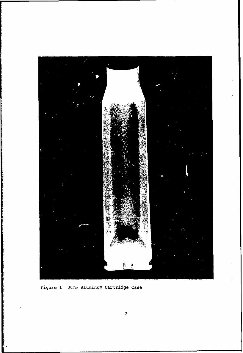
Figure 1 30mm Aluminum Cartridge Case
2
case datum line to bolt face have been established as restrictiveguidelines for the gun designer.
The rear end of each cartridge case protrudes out of thebarrel and is unsupported by the sidewall of the latter. Nat-urally, it is very desirable to hold the length of the unsup-ported case area to a minimum. Preliminary restrictive guide-lines for the gun designer were established. Within the unsup-ported rear end of the cartridge case falls the area of the caseextractor. The design study allotted sufficient space for asturdy and strong extractor without sacrificing too much rearend support.
The final gun chamber design is shown in Figure 2, Chamber
30mm.
PROPELLANTS
1. General
The preliminary cartridge case design was based on thedata provided in the RFP (projectile weight = 5,000 grains, muz-zle velocity = 3,500 fps, and maximum chamber pressure = 60,000psi) and the following calculations and assumptions.
2. Propellant Evaluation
The question of propellant type and characteristics wasinitially considered in order to establish the required casevolume. This evaluation was developed as follows:
RFP Specifications: Projectile weight - 5,000 grains(0.7143 lb.)
Diameter - 30mm(l.1811 in.)
Muzzle velocity - 3,500 fps
Maximum chamberpressure - 60,000 psi
Calculated: K.E. = W V2 = 0.7143 x 35002/2X32.1742g = 135,975 ft-lb. muzzle
energy of projectile with-out propellant
Assumption: If the propellant translated 30% of itspotential energy to emergence of the pro-jectile from the muzzle, then 135,975/0.30 = 453,250 ft-lb. would be requiredfrom the propellant, and if a propellantcontained 1,355,000 ft-lb. energy perpound, 453,250/1,355,000 = 0.334 lb. ofpropellant would be required. This con-verted to 0.334 lb. x 7,000 grains per lb =2340 grains of propellant. Thus, 2340 gr/200 gr per cubic inch = 11.7 cu. in. for
3

C) L C)
ama
0 0j
OL.an 0
'No20
r y-
S~ ~.04

propellant, or 2340 gr/250 gr per cubicinch = 9.4 cu in. for propellant would beneeded.
3. Suggested Propellants
Propellants suggested by propellant manufacturers were:
a. Olin Mathieson, East Alton, Illinois
WC-880 (Spherical Powder)
Volume - nearly 20 cu in.Weight - about 2100 grains For 90 in. pro-Maximum Pressure - 53,000 psi jectile travel
Volume - nearly 11 cu in.Weight - about 2350 grains For 80 in. pro-Maximum Pressure - 58,000 psi jectile travel
Action Time - 3.8 millisec.Time-to-peak Pressure - 1.6 millisec. 3Propellant Density - 0.96 g/cc (243 grains/in.3)
b. Hercules, Wilmington, Delaware
Hercules No. - HES6928
Volume - about 13 cu in. (for 85 in. projectiletravel)
Weight - 2650 grainsMaximum pressure - 58,000 psiBurn-out Time - 2.5 millisec.Time-to-peak Pressure - 1 millisec.Propellant Density - 227 grains/in.
3
Propellant Grain - 7% NG, d -0.02 in., OD- 0.15 in.L - 0.25 in., Cool Burning
(27000K, 24270c, 44000F),Methyl Centralite
c. Canadian Industries Ltd., Montreal, Quebec
Methyl Centralite (5.9%) with 0.024 to 0.27 in. web
Volume - 10 cu in. (85 in. from case head tomuzzle)Weight - 2250 grainsMaximum Pressure - 57,600 psi (3610 ft/sec and0.0242 in. web)
Action Time - about 4 millisecTime-to-peak Pressure - 1 to 1.5 millisec.Propellant Density - 0.89 g/cc (225 grains/in.3)
d. Du Pont de Nemours, Wilmington, Delaware
IMR-8325 or IMR-8261M with loading densities of.92 and .95 gram per milliliter.
5

4. Actual
In actuality, the final firings used 2350 grains ofC.I.L. 1379C. At .966 specific gravity, this occupies 9.62 cuin. Data for this propellant is shown in Table I.
TABLE I. PROPELLANT DATA
Manufacturer - Canadian Industries LimitedType: SPDN Lot: EXP - 1379-C Batch No. 3739Analysis of Nitrocellulose
Blends % Nitrogen % E/A. Sol. K1 Test Stability65.5 0C 134.5 0C
C(l) 205Average 13.11 35.80 36+ 30
FINISHED PROPELLANT TEST DATA
CompositionConstituents Formula % C.I.L.%
Nitrocellulose Remainder 93.52Methyl Centralite 6.0 Nominal 4.20Diphenylamine 0.7 to 1.0 0.83Pot. Sulphate 1.5 Maximum .61Lead Carbonate 0.6 to 1.0 0.84Moisture 1.0 ± 0.25 1.00Residual Solvent 1.1 Maximum 0.77Volatiles Total 2.35 Maximum 1.77Graphite --- 0.25Dust and ForeignMatters 0.075 Maximum 0.01
GRAIN DIMENSIONS (in inches)
Length Diameter Perforation Diameter Mean Web
Die .0909 .101 .015Finished .0825 .0657 .0071 0.0293
The case volume behind the projectile was thereforechosen to be between 10 and 11 cu in. The case drawn for thisproposal, as shown on RE-5-102 (Figure 3), contained approxi-mately 10.7 cu in. behind the projectile.
The extra case volume was selected to provide for thefollowing possibilities:
a. Heavier projectiles with same velocity
b. Higher velocity with same weight projectiles
c. Decreased velocities due to barrel erosion
6
I °. .

I~w H''--
IxI
0 4-1
A ~it t
______ ~ ~ d4

d. Shorter barrel
e. Lower bulk density propellant
f. Recommended 14% of case volume as air space
g. Lower energy propellant
h. Increased projectile insertion into case
If none of these prove to be required or desirable, thecase volume could be reduced up to 1.4 cu in. and the case lengthby 0.7 inches.
ANTICIPATED DESIGN DIFFICULTIES
No development program could be expected without its in-herent difficulties; however, the probability of successfulaccomplishment of the development is enhanced if these diffi-culties are recognized beforehand. The development program for
this 30mm aluminum cartridge case was no exception, and the fol-lowing were recognized as possible problem areas:
1. Primer Setback, Primer Leaks, and Blown Primers
Difficulties of this type had been encountered inearlier efforts to develop aluminum cartridge cases as substi-tutes for existing brass or steel case designs. Severe primerleaks or blown primers result in varying degrees of hot gaserosion of the cartridge case head. Such difficulties are be-lieved to be caused by undue expansion of the case head underpressure, surface irregularities in the primer pocket which wereintroduced during fabrication of the case or insertion of theprimer, and inadequate design attention to the need for primerobturation.
The general approach to elimination of primer area dif-ficulties was to recognize these potential problems in thedesign of the cartridge case head and primer pocket and to exer-cise due caution in producing a smooth primer pocket and keepingit smooth during primer insertion.
Further discussion of this problem is presented in theTest Firing section of this report.
2. Splits, Ruptures, and Case Erosion
Difficulties of this type had also been encountered inboth earlier and current efforts to substitute aluminum for brassor steel designs. Either a longitudinal split or a circumfer-ential rupture can lead to extensive hot gas erosion of the caseand damage to the barrel. Such erosion is believed to be asplit or rupture which occurred early in the interior ballisticscycle. Ruptures occurred mostly on caliber .50 cases made adecade ago, or earlier and were believed to have been caused bycircumferential irregularities, sometimes called "shock lines,introduced into the case walls during fabrication. Ruptures werenot a problem in the current efforts.
8
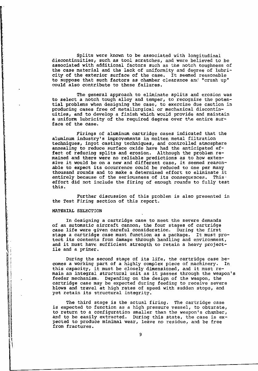
Splits were known to be associated with longitudinaldiscontinuities, such as tool scratches, and were believed to beassociated with additional factors such as the notch toughness ofthe case material and the lack of uniformity and degree of lubri-city of the exterior surface of the case. It seemed reasonableto suppose that such factors as chamber clearance an(' "crush up"could also contribute to these failures.
The general approach to eliminate splits and erosion wasto select a notch tough alloy and temper, to recognize the poten-tial problems when designing the case, to exercise due caution inproducing cases free of metallurgical or mechanical discontin-uities, and to develop a finish which would provide and maintaina uniform lubricity of the required degree over t1&e entire sur-face of the case.
Firings of aluminum cartridge cases indicated that thealuminum industry's improvements in molten metal filtrationtechniques, ingot casting techniques, and controlled atmosphereannealing to reduce surface oxide have had the anticipated ef-fect of reducing splits and erosion. Although the problem re-mained and there were no reliable predictions as to how exten-sive it would be on a new and different case, it seemed reason-able to expect its occurrence could be reduced to one per manythousand rounds and to make a determined effort to eliminate itentirely because of the seriousness of its consequences. Thiseffort did not include the firing of enough rounds to fully testthis.
Further discussion of this problem is also presented inthe Test Firing section of this report.
MATERIAL SELECTION
In designing a cartridge case to meet the severe demandsof an automatic aircraft cannon, the four stages of cartridgecase life were given careful consideration. During the firststage a cartridge case must function as a package. It must pro-tect its contents from damage through handling and environment,and it must have sufficient strength to retain a heavy project-ile and a primer.
During the second stage of its life, the cartridge case be-comes a working part of a highly complex piece of machinery. Inthis capacity, it must be closely dimensioned, and it must re-main an integral structural unit as it passes through the weapon'sfeeder mechanism. Depending on the design of the weapon, thecartridge case may be expected during feeding to receive severeblows and travel at high rates of speed with sudden stops, andyet retain its structural integrity.
The third stage is the actual firing. The cartridge caseis expected to function as a high pressure vessel, to obturate,to return to a configuration smaller than the weapon's chamber,and to be easily extracted. During this state, the case is ex-pected to produce minimal wear, leave no residue, and be freefrom fractures.

The fourth stage completes the cycle with the cartridgecase passing through the ejection system and becoming scrapmaterial.
If the customary cartridge case materials are considered inthe light of the above criteria, it is apparent that each mat-erial has its own strengths and weaknesses. Cartridge brass,for example, performs fairly well as a packaging material but issubject to severe corrosion in some environments and lacks suf-ficient strength to withstand abusive handling. As a machinepart, brass has optimum properties, and when properly supported,performs well as a high pressure vessel, but is undesirablyheavy within the context of an aircraft system where weight isimportant. In the fourth category, that of becoming scrap metal,lies another major area of disadvantage due to the high cost andthe resulting loss of brass as a strategic material. In con-trast, a heat-treated steel cartridge case provides an optimumpackaging material, particularly when plated with zinc to pro-vide cathcdic protection. A steel case functions well as amachine part and as a high pressure vessel but does producegreater wear on the mating surfaces of the weapon. The weightof the steel case, as with brass, is a disadvantage from thestandpoint of the load in an aircraft. As scrap, steel is ex-cellent since it does not represent any great loss of strategicmaterials.
Aluminum seems to fulfill all of the desirable features fora cartridge case material. In the higher strength heat-treat-able alloys, suitable mechanical properties are developed togive "package-ability"; with the application of suitable coat-ings and heat treatments, the cases can be expected to stand upwell under handling and environmental conditions. Unfinishedaluminum's tendency to gall and seize in contact with movingsteel parts and the abrasive nature of an anodic coating, com-bined with the obvious shift in the center of gravity of theround, may present a problem in existing, feeder designs. There-fore, the use of lubricant-impregnated coating alleviates partof the problem, but the center-of-gravity difference must beconsidered and allowed for during weapon design. Aluminum cart-ridge cases have successfully functioned as high pressure vessels.
The tendency for a cartridge case to stick in the chamber
and cause extraction problems is primarily a function of:
o the materi2. modulus of elasticity;
o the radial clearance between the cartridge case andchamber wall;
o the thickness of the chamber;
o the taper of case and chamber; and
o the coefficient of friction between the cartridge caseand the chamber wall.
10

CARTRIDGE CASE DESIGN CRITERIA
I. Propellant Weight
Propellant Weight - 2340 grains
2. Case Volume
Case Volume = Propellant Weight = 2340 grains
Estimated Propellant Density 225 gr/cu in.
=10.40 cu in.
3. Maximum Working Chamber Pressure
Maximum Working Chamber Pressure = 60,000 psi x 1.14(Saf ety Factor)
= 68,400 psi
4. Maximum Cartridge Case Diameter at Head
The final design (Figure 3) shows a maximum case out-side diameter of 1.78 inches although earlier calculations beganwith an outside diameter of 1.92 inches. With a case outsidediameter of 1.92 inches, the wall thickness of the barrel wouldbe approximately 0.73 inch. Since gun weight would be excessiveunder these conditions, the case chamber diameter was reduced to1.75 inches (while the volume was kept constant), permitting asignificantly smaller barrel wall thickness of 0.57 inch minimumat the chamber. This relationship, which is illustrated graph-ically in Figure 4, limits chamber wall deflection to 0.004 inchon the radius.
5. Case Material
The following data, supplied by Alcoa, are applicableto X7475 alloy in*T73 condition:
Typical Tensile Strength (ultimate) = 72,000 psi
Typical Tensile Yield Strength = 62,000 psi
Typical Shear Strength - 43,000 psi
Modulus of Elasticity - 10.4 x 10⁶ psi
6. Muzzle Energy
Muzzle Energy = W V2 = 136,000 ft-lb
Wb = Projectile weight (lb)
Vo = Muzzle velosity (ft/sec)
g = Acceleration of gravity (ft/sec2)*T73 is a patented Alcoa process
11
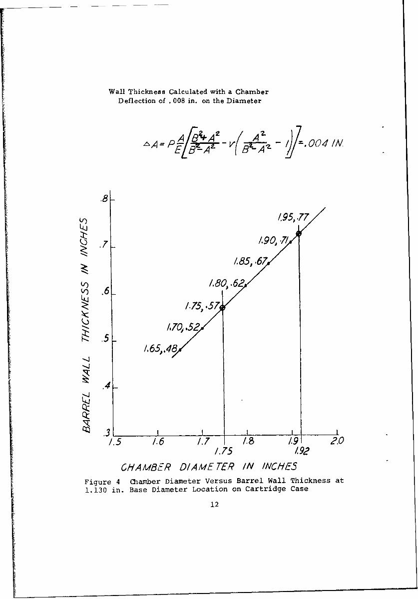
Wall Thickness Calculated with a ChamberDeflection of . 008 in. on the Diameter
"A= 7E[§ A - P' _ •
.3x-
,95,.77
/907/
1.85, .67
/.75, .5
/.i51.65,,48
-4-.4
.4_
QCT
'~ .31.5 1.6 1.7 1.8 19 2.0
1.75 /92
CHAMBER DIAMETER IN INCHES
Figure 4 Chamber Diameter Versus Barrel Wall Thickness at1.130 in. Base Diameter Location on Cartridge Case
12

7. Muzzle Impulse
1= Wb V° + Wp V0 = 96.00 lb/sec
g 2g
Wb = Projectile weight (ib)
VO = Muzzle velocity (ft/sec)
Wp = Propellant weight (lb)
g = Accerleration of gravity (ft/sec2)
DIMENSIONAL CHARACTERISTICS
1. General
The dimensional characteristics can certainly be deter-mined during the design phase of the weapon. The coefficient offriction appears to be most favorable, based on recent tests con-ducted by the Alcoa Research Laboratories, where the aluminum,with suitable surface treatments, has a coefficient considerablybelow that of either zinc-plated steel or cartridge brass. Ifthe alloy used and the design of the cartridge case are correct,the only detrimental feature would be the lower tear strength/yield strength ratio. This ratio describes the ability of amaterial to resist propagation of cracks in either an elastic orplastic stress field. The curves shown on Figure 5 are takenfrom current research work being conducted at the Alcoa ResearchLaboratories and show the relationship between cartridge brassand possible aluminum alloys under consideration for use in car-tridge case manufacture. Improving the characteristic of thisratio through modification of chemistry and processing tech-niques was accomplished.
a. Explanation of Engineering Curve (Figure 5Tear Strength/Yield Strength Ratio)
The curves shown illustrate one of the character-istics which is felt to be the key to success in the utilizationof aluminum for cartridge case manufacture. The curves show therelationship between tear strength and yield strength of variousaluminum alloys and various heat treatments in relation to thesame characteristic in 70/30 cartridge brass. The data wereobtained using sheet specimens, conventional for yield strength,and notched specimens for tear strength measurements. The spec-imens had been rolled to various dimensions and selectively heat-treated to represent various areas of a brass 20mm cartridgecase design.
The continuous line, identified Al-Zn-Mg T6, rep-resents the present behavior for this alloy system, and thedashed line, identified Al-Zn-Mg 1.5 Cu,establishes the be-havior for that alloy system.
13

2.0 _____Al-Zn-Mg T6
Al-Zn-Mg-1. 5Cu1.8 C
1.60T 70 - 30 Brass
1.65456_-2-- old Rolled
5456-H32& StressN Relieve
z a ?0 24-73__1.4 X7475-T6
H-
7075-T73
H
0.8 __________7178-T6 km,
1.4 5 6 7 8____
YIELD STRENGTH (KPSI)I Figure 5 Tear Strength/Yield Strength RatioVersus Yield StrengthI 14

The selection of X7475 (selecLed chemistry 7075)becomes obvious from a study of its relationship to the limitsof its alloy system. The use of a T73 heat treatment will shiftthe point shown for T6 slightly higher and to the left.
The traditional problem of stress corrosion crack-ing, encountered with high strength aluminum alloys, has beenessentially overcome through the use of the T73 , a two-stepaging treatment. Tear/yield curves illustrate this effect oftreatment on mechanical properties. In general, it is consid-ered that the mechanical and physical properties of aluminum,combined'with modern finishing techniques, give aluminum everychance and possibility of success for use in the manufacture ofautomatic aircraft cannon cartridge cases.
The selection of the alloy to be used became afairly straightforward decision when the physical and mechanicalproperties of the available alloys were screened using the cri-teria listed above. The alloys which had already been consideredwere 6066, 2024, and 7075. Such factors as adequate ductility,final strength levels, susceptibility to stress corrosion,availability, compatibility with finishing methods, natural agingtendency, sensitivity to processing tolerances, etc., lead rap-idly to the conclusion that the "right" alloy was X7475 ( a modi-fied 7075 alloy), heat-treated to condition T73. The modifica-tions of chemistry represented by the alloy, now designatedX7475, was a restriction of the chemical limits of 7075 and doesnot present a problem for future procurement from mu-tiplesources. The practice of limiting chemistry and impurity levelswithin the published ranges of materials is a common practice inthe marketing of high strength 7000-series aluminum alloys.
2. Cartridge Case Ccnfiguration
With regard to cartridge case configuration, the tra-ditional problem of meeting propellant volume requirements with-out an exaggerated length-to-diameter (L/D) ratio had to be con-sidered. As the length of the cartridge case increases to sat-isfy propellant volume requirements, the problems in gun feederdesign increase. As the diameter of the cartridge case increases,the effective stress increases, tending to rupture the case onits circumference: in addition, the size and thickness of theweapon chamber become prohibitive. If an aluminum cartridgecase is to function properly in an automatic gun, the L/D ratiomust be carefully established to provide optimum volume alongwith proper frictional holding forces during the pressure rise,and there has to be a sufficient sidewall strength to preventlongitudinal and circumferential rupture throughout the firingcycle. The final L/D ratio and the powder volume dictate thecartridge case wall and head dimensions. The sidewall dimen-sions must be carefully designed to produce the proper incre-mental obturation and frictional lockup beginning at the mouthof the case and ending at the extractor groove relief. If this
15

design fundamental is not carefully observed, the case cannot"grow" in longitudinal direction and a segment of the case willbe placed in a triaxial stress, permitting a fracture duringthe initial pressure rise. The wall thickness must also be con-sidered in the relationship of gun chamber clearance and theamount of elastic deformation allowed by the design of the gunchamber. If this design fundamental is ignored, longitudinalcracks can occur. The head section dimensions are critical fromthe standpoint cf the ability to withstand the imposed internalstresses in the unsupported case section in the extractor groovearea; the ability to expand under the imposed stresses and re-tention of the primer, and the ability to return to dimensionswhich will continue to provide clearance for extraction andprimer retention. Some of these characteristics are illustratedby the curves in Figure 7 that show the behavior of steel andaluminum cartridge cases under conditions imposed in 20mm auto--matic aircraft guns, as generated by the time-pressure condi-tions illustrated in Figure 6.
a. Explanation of Curves (Figures 6 and 7
The curve on Figure 6 illustrates the typical time-pressure curve for a steel-cased 20mm round. As noted, this in-formation was gained using a 20mm Mann barrel and an IMR stan-dard propellant load.
Figure 7 illustrates the factors which must be con-sidered in the design of new cartridge cases. As noted, threecharacteristics are most important:
(1) The minimum obturating pressure: This isdefined as the minimum pressure that would cause a given areaof a cartridge case to expand and just touch the chamber wall.This curve is a function of the material modulus and the casediameter.
(2) The minimum pressure for case separation:This curve shows the required chamber pressure to cause the caseto separate circumferentially, assuming there is no rearward sup-port. The curve is a function of the ultimate tensile strengthof the material and the case dimensions.
(3) The interfacial radial strength at 60 KPSIinternal pressure: 'his curve illustrates the force holdingthe cartridge case against the chamber wall at maximum chamberpressure. The component of force multipiied by the coefficientof friction gives the theoretical force or pressure required towithdraw the case from the chamber. It is important to notethat this curve is a function of pressure and dimensions and isindependent of the cartridge case material.
By utilizing this information, a cartridge case wasdesigned that can successfully withstand the stresses imposedand does return to dimensions suitable for proper extraction.This information also leads to accurate computation of the max-imum pressure that can be used but prevents case failure duringthe unlock and extraction portion of the cycle.
16

DATA FROM:20mm MANN BARRELPROJECTILE; MK 11 MOD 0CASE: MK 5 MOD 0PRIMER: M52A3B1
70L
W~ 50 _ _ _ __ _ _ _
P4
40
S 30 _ _ _ __ _ _ _
PORT PRESSURE
20 _ _ _ _ _ _____
17

INTERFACIAL RADIAL STRESS AT 60 KPSI - X- X-MINIMUM PRESSURE FOR CASE SEPARATION -0----MINIMUM PRESSURE FOR OBTURATION -- O---O-
60
0 X - - ) (--50 k ._____-----___
40 X
30 _ _ _
C1030 SteelHardened &K -Tempered
20010 0...
10 _________ 7075-T6
1 2 3 5INCH ES
Figure 7 Three Case Design Factors
18

DESIGN ANALYSIS
In order to prove the validity of the design previouslydepicted on Figure 3, static stress calculations were conductedas shown:
1. Chamber Wall Expansion
Calculation in Figure 8 shows the chamber expansion tobe .004 in., assuming a chamber pressure of 60,000 psi arid bar-rel material FS4150 (MIL-S-46047) are being used.
2. Stress in Chamber Wall
Calculation in Figure 9 shows the stress in the bar-rel chamber wall, under the expansion of .004 in., to be 137,142psi tensile strength. The stress condition is within thestrength of the barrel material FS4150 (MIL-S-4607) in heat-treated condition Rc 32-36.
3. Stress Check of Case Base
Calculation in Figure 10 shows the shear stress in thecase base to be 44,030 psi.
SURFACE FINISH
The surface finish was of prime importance to the successful
completion of this program. The problems of cartridge casecracking, general corrosion, retention of primers, and properextraction characteristics made the subject of surface finishworthy of a correlative study.
A suitable surface finish, correlated to the alloy requiredfor the desired mechanical and fabricating properties, must pro-duce corrosion resistance, lubricity, propellant compatibility,abrasion resistance, flexibility, and retention of initial ap-pearance on the aluminum case body. Thus, the development of anoptimum finish was a vital part of the total program for util-izing the advantages of aluminum in this application. A furtherdiscussion of surface finish is given in Section V, SurfaceFinish.
SHORTER CARTRIDGE CASE DESIGN
In October, 1969, at the request of the Air Force ArmamentLaboratory, a design investigation to shorten the cartridge casewas carried out by making the following basic changes:
1. The base diameter was increased by .110 in.
2. The sidewall taper was increased to .024 in. basic taperper inch on diamter.
3. The shoulder included angle was decreased to 380.
19

A_ Bz+ A9B
REF 'FORMULAS FORCHAMBER STRESS AND STRAIN" BYROARK PAGE 276 CASE HO.29A =CHAMBER RADIUS -. 8 75 1IN.
P CHAMBER PRESSURE 600 00 PS.I.E MODULUS OF ELASTICITY -30x10 6B -- BARREL OUTSI DE RADIUS-- 1.4 IN.V POISSON'S RATIO .26
,A 60,0'~875 [4.875 -(_8752A A ---6 0,00 0 0 o'iT -.--T _'6 -
AA == .003942 OR -004 IN,
Figure 8. Chamber Wall Expansion
20

A -
E= MODULUS OF ELASTCITYK=0XIO6
5--ESS e = A A -.00E- e/A A=CHAM3EP PAD.=.87b
6 (e8TF~SS=30X 10(eSTIPESS-
A
STI KES - (30 X 106) (.004) 137142 PS.I..875Figure 9. Stress in Chamber Wall
21

CALCLATE .AS CONICAL .SHEAQ-ING SE-CTION EXTENDING INTO EXTPACTORGRPOOVE AT 45.AREAZ OF CONICAL SUP-FACE OF FQUSTUMOF A CONE IN SHEAR A=I1.5708SS(D+d)
SHEAR STRESS= P4(.5O))d±
P = MAXIMUM CHAMBER RR-ESSURE=7Q,000 PSId =SMALL DIAMETER OF FRUSTUMv OF C-ONE=I.2 IN,5 = LENGTH OF CONICAL1 SURFACE= .388 IN.D = LARG-E DIAMETER OF FRUSTUM OF CONE=I.Th IN.
SHEARSTRES (4)(1.5708) (.388)(1i75+.20)
SHEAR STRESS= 44,030 P.S.I.
THIS CALCULATION SHOWS THAT THESHEAR STR-ESS AT THE CARTRIDGEBASE IS BELOW THE STRENGTH OFX 7475 -T73 ALUMINUM ALLOY.
Figure 10. Stress Check of 30mm AX Case Base
22

The objective of the above-mentioned changes was to reducethe overall length of the cartridge case .50 inch without de-creasing the interior volume an appreciable amount. No furtherengineering work was carried out on this shortened case becausethe advantage of length reduction was not great enough to bal-ance the disadvantages incurred by the increase in barreldiameter.
PROPOSED PEDESIGN REQUESTED BY THE AIR FORCE
The first case redesign was designed with a base diameter ofapproximately 44mm. The volume of the case was calculated to be10.2 cu in. The redesign and the original case design were pre-sented to the Air Force during a review meeting on 19-20 August1969. However, the RE-5-102 case (Figure 3) was accepted for thedesign of tools and gages and the fabrication of cases. Thelarger volume of the original design was considered better be-cause of the flexibility required for propellant selection.
INTERIOR CASE VOLUME REDUCTION
Part of the design evaluation was to attempt to reduce thevolume required for propellant so that the case could beshortened. The final propellant charge was established as 2350grains, which, if the assumption is made that the approximateloading density is 240 grains per cu in., requires a propellantvolume of 9.8 cu in. There are several disadvantages in havingexcess volume in a cartridge case, namely,
1. Ignition prcblems, when all the propellant is drivenforward from the flash hole as the round is chambered duringthe feeding cycle.
2. Unnecessary cartridge length resulting in extra weightand gun feeding problems. In order to minimize the case volume,a 6% clearance volume was assumed to be sufficient. The follow-ing computation shows what the interior volume requires:
Volume for propellant 9.8 cu in.
Clearance volume 0.6 cu in.
Volume of projectile base 1.0 cu in.
11.4 cu in.
Since the Amron AX case now has 12.0 cu in. total vol-ume excluding the primer cavity and flash hole, 0.6 cu in.could be eliminated.
23

SECTION II
MATERIAL
GENERAL
The material used for the 30mm cartridge case program is
the Alcoa alloy X7475. The purchased temper is OE4 which is aspecial full anneal temper. This temper imparts the maximumductility and thereby precludes the need for extensive andcostly long-cycle process annealing.
RAW MATERIAL
X7475 Chemical Composition
Silicon Iron Copper Manganese Magnesium
0.10% max. 0.12% max. 1.2 - 1.9% 0.06% max. 1.9 - 2.6%
Chromium Zinc Titanium Others Aluminum
0.18 - 0.25% 5.2 - 6.2% 0.06% max. Each 0.05% RemainderTotal 0.15%
The as-received plate material has a fir;e grain size and a
Rockwell Hardness of R H92-93.
Incoming inspection activities included, but were not lim-ited to, the following:
1. Check analysis of key elements using Atomic AbsorptionSpectrophotometer Techniques.
2. Rockwell hardness testing.
3. Metallurgical micro- and macroexamination.
4. Determinations of percent IACS.
METALLURGICAL PROCESSING
After discs were blanked from the-plate, they were annealedat 6300 - 6750 F for 30-90 minutes, resulting in a Rockwell corehardness of RH8 9 - 87.
The lubrication process for the metal-forming processthrough third draw was that of a precleaned surface, followedby an application of a zinc phosphate substrate overlayed andimpregnated by a lubrication coat of zinc stearate. Specificchemicals used were as follows:
1. Pre-cleaning - Wyandotte Aldet
2. Zinc phosphate - Bonderite 170X
24

3. Zinc sterate - Bonderlube 234
4. Post-cleaning - Oakite 33
All subsequent lubrication was conducted using the afore-mentioned pre- and post-cleaning supplemented with a basic solu-tion of Swift Soap Chips at a concentration of J.2 - 16 oz/gallon.
Studies conducted indicated that other lubricants, as pro-duced by Irmco, E. F. Houghton, Texaco, and Johnson's Wax, werepromising but did not offer any marked improvement in performanceover that initially selected for use. A study of the mass pro-ducibility could well show the need for a lubricant easily ap-plied by the dip or immersion process and imparting the sameexcellent surface finish but which would br more economical andone which could be cleaned in a more straightforward manner.
In-process annealing was conducted at 6300 - 675 0F for 30 -
90 minutes. Resulting hardnesses were in the range of the RH90 -
95. Starting hardness for the cold worked parts was in therange of RH94 - 98.
The metallurgical quality of X7475 alloy is consideredsuperior to that of any other alloy suitable for use in makingaluminum cartridge cases. The cleanliness of the metal and thefine grain size contribute to this feature. The highly inno-vative Alcoa 467 process is directly responsible for the alloy'ssuperior fracture toughness. This process was develped speci-fically to enhance the toughness of high purity 7000-seriesalloys (AI-Zn-Mg-Cu series). The mechanical properties featuresof the cartridge cases are discussed in Section I of this report.
Some time limitations were observed on parts subjected tothe process anneal relative to the time delay between annealingand cold working. The time limit appears to be approximately72 hours and affects the concept of high productivity, but itcan be compensated for by proper scheduling.
The solution heat treatment which results in minimizedstress corrosion susceptibility was conducted in a PacificScientific solution heat treatment furnace designed exclusivelyfor high quality aluminum alloy cartridge cases. This furnaceis provided with a unique protective atmosphere which inhibitsharmful oxidation. Quench delay times into cold water can bekept within 4 - 7 seconds. Artificial aging is conducted in ahigh rate recirculation oven. Approximate heat treatment timesand temperatures follow:
Solution 8800 - 950 ° F
Time 30 - 120 minutes
25

Quenchant 500 - 850F Water
Artificial agring 250°F - 325°F with time rangesfrom 24 hours at 250OF to : and
3250 F.
PROPERTIES
Typical mechanical properties follow:
PercentYield Ultimate Elongation R30T
X7475-T6 73,000 83,000 10 74
PreferredX7475-T73 62,000 72,000 8 74Generally observed tear strength/yield strength ratio is1.2 at a yield strength of 75,000 psi.
Alloy X7475 can be processed through metallurgical opera-tions without difficulty, and physical/mechanical propertiescan be tailored to those needed to provide high quality alum-inum cartridge cases for the T73 temper.
Raw material should be purchased as plate at proper thick-ness of alloy X7475 - OE4 Temper, fine grain size, ar. of cart-ridge case quality.
Chemical composition limits of X7475-T73 are given in thissection of the report.
Minimum hardness measured at the internal portions of thehead section and throughout the wall section shall be R30T 72minimum. The mechanical properties of tensile and percentelongation, measurel at a point 1.5 to 2.0 inches from the faceof the head section, shall be:
Yield psiUltimate (.2% offset) Percent Elongationpsi minimum Minimum (I in. gage) minimum70,000 60,000 8
26

SECTION III
MANUFACTURING PROCESS
GENERAL
Production of a ballisticdlly successful aluminum cartridgecase for the 30mm program depends heavily on a careful selectionof the correct alloy and of the quality control measures inmonitoring each of the operations. The backward extrusion fromrod method of manufacturing was investigated but the blarnk, coincup and draw process was chosen as the most appropriate andeconomical method for high production, high volume of manufact-uzing.
A few advantages other than the economical ones are thefollowing:
1. Superior physical properties were obtained in thecritical head section because of the loop grain flow.
2. The fact that the metal that will form the sidewall wasplaced in circumferential and longitudinal tension during thedrawing operation makes the process self-cleansing, because anyserious mechanical or metallurgical flaws will physically des-troy the part or it becomes an easy visual rejection.
MATERIAL
Raw material was received in strip form, and discs wereblanked from these strips. This gave the necessary loop grainflow in the head section of the case.
MANUFACTURING PROBLEMS
1. Blank
After manufacturing a few blanks, it was discoveredthat there was insufficient clearance between the punch and die.The punch had to be reground several times before the properclearance was established.
2. Coin Cup
After tool tryout of this operation, it was felt thatthe base thickness was insufficient for the heading operation.Therefore, the angle of the punch had to be regound in orderto trap more material in the die. This was accomplished withthe first try and produced the necessary base thickness.
3. First through Fourth Draw
Tool tryout of these operations proved to be no pro-blem, and everything went through a smooth manufacturing process.
h 27

4. Head and Indent Primer Cavity
After heading and indenting a few cases, they were heat-treated to see whether the primer pocket would change during theheat-treating process. After the heat-treating process, thecases were rechecked and the primer pocket had not changed.
5. Head Turn and Drill Flash Hole
This operation presented no problem. All that was nec-essary was to check the part and maintain the correct speed andfeed recommended for the tooling.
6. Pre-taper and Taper
In order to prevent any distortion in the final con-figuration of the cartridge case, it was necessary to go to apre-taper prior to final tapering of the case. The case waspre-tapered and then heat-treated. After heat-treating, thecase was final tapered.
7. Photograph
Figure 11 illustrates the manufacturing operations dis-cussed in the preceding paragraphs.
PROCESS DEVELOPED
Table II Operational Summary, lists the operations necessaryto produce the 30mm aluminum cartridge case.
28

.......... 0
29

TABLE II. OPERATIONAL SUMMARY
Operation OperationNumber Description
10 Receive and check order
20 Receiving inspection30 Blanking
40 Wash
50 Anneal blanks (Condition "0")
60 Bonderize and Bonderlube
70 Coin cup
80 Wash cups
90 Anneal
100 Bonderize and Bonderlube
110 1st Draw
i20 Wash
130 Anneal
140 Bonderize and Bonderlube
150 2nd Draw
160 2nd Draw Trim
170 Wash
180 Anneal
190 Bonderize and Bonderlube
200 3rd Draw
210 3rd Draw Trim
220 Wash
230 Anneal
240 Bonderize and Bonderlube
250 4th Draw
260 4th Draw Trim
270 Head and Indent Primer Cavity
28u Head Turn and Drill Flash Hole
290 Wash
300 Anneal
310
320 Pre-taper trim
330 Pre-taper
30

TABLE II. OPERATIONAL SUIARY (Concluded)
340 Wash
350 Heat Treat T-4
360
370 Taper
380 Final Wash
390 Artificial Age
400 Final Trim
410 Mouth Age
420 Size Mouth
430 Final Hardness and Tensile Test
440 Anodize
450 Mark
460 Final InspectionFinal Insp. - Lot Verification-
SamplingFinal Insp. - Lot Verification-
SamplingFinal Insp. - Lo. Verification-
SemplingFinal Insp. - Salt Spray TestFinal Insp. - Hardness Test
470 Pack and Store Prior toAssembly
31

SECTION IV
IGNITION SYSTEM
GENERAL
An ignition system was developed around Frankford Arsenal20mm XM-115 primer that suited the pressure-time curve of thepropellant burning.
If the primer had been too small and generated insufficientpressure and flame to ignite enough propellant within the propertime frame, "hang fires" could have resulted.
On the other hand, if the primer had been too large and hadgenerated sufficient pressure and flame to ignite all grains ofpropellant simultaneously, too high pressure may have developedtoo early and rapidly.
Thus, the optimum relationship was developed between thepropellant pressure-time curve and the primer fuze and type anddid not require the use of flash tubes.
IGNITION SYSTEM CANDIDATES
1. XM-115 primer (Frankford Arsenal X10543585) is cur-rently used in the 20mm M187E1 cartridge case fired in theHispano-Suiza 820 gun. (M139 is the Army designation of thisgun.)
2. M36AlBl primer is presently used in all mechanically-ignited ammunition such as the M90-series 20mm. This primerwould have been inserted in a primer pocket similar to that inthe 20mm Navy Mk 5 case.
3. FA-1054281 flash tube would have been used in con-junction with the M36AlBI primer. It is presently used in the30mm XM193 cartridge case, fired in the U. S. Army 30mm XM140gun carried aboard helicopters.
4. Percussion primer assembly (Type T) is a threaded,flash-tube assembly which contains standard primer M36 and iscurrently used in the 27.5mm cartridge case being developed byAmron for Aerojet for another program.
5. M52A3BI primer is presently used in all electricallyignited ammunition such as the M50-series and Mk 100-series 20nn.This primer would have been inserted in a primer pocket similarto that in the 20mm Navy Mk 5 case.
PRIMERS
The proper primer, primer pocket, flash hole and propellantwere selected to constitute the desired ignition train.
These experimental XM-115 primers used in the first firingtests had about .003 in. interference fit in the primer pockets.
32

This was found to be almost ideal from previous studies. Sub-sequent studies of 100 primer and primer pocket dimensionsrevealed:
1. Interference on diametric fit of .0008 in. to .0056 in.
2. Primer ellipticity of .0009 in. to .0034 in.
3. Average primer diameter of .3748 in. to .3781 in.
4. Primer height of .2655 in. to .2703 in.
5. Pocket diameter of .372 in. to .373 in.
6. Pocket depth of .264 in. to .266 in.
7. Pocket positive taper of .001 in.
In actual use, the usual primer insertion device exertedinsufficient pressure to seat the primers properly. A new prim--ing device was constructed to alleviate this difficulty. Anarbor press was used to seat the primers .003 in. ±.001 in.below the base of the case. As was seen by examining insertedprimers, some of the primers were not seated squarely in theprimer pockets due to irregularities in the lip of the primercup.
Examination of unused XM-115 primers revealed that someanvils are not seated squarely in the primer cup. Therefore, aplane across the anvil legs would not be parallel to the plane ofthe primer cup bottom. This helps to account for the lack ofsolid 3600 contact between assembled primers and their primerpocket bottom as well as the presence of cocked primers ( SeeFigure 12 ).
The hardness of the primer cups was investigated, and the
following summary resulted:
1. Metallurgical Evaluation of XM-115 Primers
The microexamination of the subject product indicated:
a. The anvil and the cup are produced from copperalloy 260, cartridge brass.
b. The Diamond Pyramid Hardness (D.P.H.) of 182(Rock-well B-RB-89) for the anvil would indicate a finished temper ofextra hard.
c. The cup hardness was D.P.H. 190 (RB-91) at the side-wall and D.P.H. 100 - 110 (RB-55 to 62) at the base.
2. Conclusion
The XM-115 primer specimens are manufactured from theproper copper alloy. The anvil is slightly harder than the
33

t
Figure 12 Cross Section of Case with Inserted Primer
34

specification hardness of half hard and the cup is as-cold-workedfrom annealed strip stock. The high hardness of the anvil shouldnot affect the intended function of the product, but the highhardness of the cup sidewall will result in a yield strength of65,000 psi as opposed to 22,000 psi for an annealed cup.
During previous work with 20mm aluminum cartridge cases, thepossibility of gas leaks at the primer pocket became apparent.It has been noted that high yield strength in the sidewall of aprimer inserted into an aluminum cartridge case will act as acontributing factor for primer gas leaks, because the high yieldstrength will not allow proper sealing between the cup sidewalland the primer cavity wall.
Primer leaks were nonexistent in all instances where thesidewalls of the primer pockets were smooth. There is evidence,though, that the work-hardened sidewalls of the primers, in con-junction with the unfinished lip of the primer cups, can producelongitudinal scratches in the pocket wall. These can, in turn,initiate primer leaks. This condition can be readily identifiediy the observance of bubbles forming following application of theprimer sealant.
At such time that future assembly of these primers intoaluminum cases becomes necessary on a production basis, it isrecommended that the primer cup lip be trimmed,follo,;ed byannealing of the work-hardened wall of the primer citp.
35

SECTION V
SURFACE FINISH
GENERAL
One of the major parts of the engineering and design studyof the 30mm aluminum cartridge case contract is surface finishdevelopment. The desired characteristics of a surface finishfor aluminum cartridge cases have been projected as follows:
1. Maintain the structural integrity of the case.
2. Resist surface oxidation and retain initial appearance.
3. Retain good resistance to stress corrosion cracking.
4. Provide sufficient anti-seize properties, both initi-ally and after prolonged field storage, to enable satisfactoryfunctioning of the cartridges under rapid fire conditions.
5. Be practical and economical for mass production.
As a result, the total finishing system must consider clear-ing and preparing the surface, applying a protective coating, andapplying an anti-seize coating.
Amron and Alcoa have concurrently, but separately, developedsurface finishing systems for application to the 30mm aluminumcartridge case.
ALCOA RESEARCH LABORATORIES INVESTIGATIONS
RECOMMENDED FINISHING TREATMENTS FOR X7475-T73 ALLOY
Extensive data have been accumulat3d in evaluating finishingtreatments applied to X7475-T73 alloy. These data include accel-erated corrosion test results and physical measurements such askinetic coefficient of friction, abrasion tests, reverse-impact,and diamond scratch hardness determinations. The data were util-ized to find coating systems having properties required for cart-ridge case application, which at the same time can be readilyapplied. Using these criteria for screening candidate finishingsystems, coatings have been selected for application to X7475-T73alloy.
The recommended cleaning processes required three differenttreatments:
1. An inhibited or non-etching alkaline cleaner to removefingerprints, oil and shop soil.
2. An acid etch in a solution containing 10% by volume of48% hydrofluoric acid and 10% by volume of 70% nitric acid atroom temperature.
36

3. A desmutting treatment at room temperature in 1:1 nitricacid to remove the light smut film which forms on the surface ofthe work during acid etching.
The first recommended finishing treatment is a thin anodicoxide coating applied in sulfuric acid at 70°F for 10 minutes.The most corrosion-resistant coating evaluated in this work waseither a dichromate-sealed or a dual nickel acetate-sodiumdichromate-sealed Alumilite coating. The first suggested seal-ing operation is carried out by immersing for 10 minutes insodium dichromate at 185 0F. The latter sealing technique re-quires 5 minute immersion in a boiling solution containingnickel acetate, followed by a ten minute immersion in sodiumdichromate at 1850F. Further corrosion protection and especiallya lower kinetic coefficient of friction can be obtained by sub-sequently applying a wax emulsion coating (deposited from a boil-ing water solution). Optimum results were obtained with thedichromate-sealed Alumilite coating with a thin film of McLube1700 fluoro-carbon lubricant (McGee Chemical Co.). The boilingwax and the fluoro-carbon lubricant treatments can be applied tounsealed Alumilite coatings, but neither is as corrosion resistantas that sealed in dichromate. A boiling water-sealed anodic coat-ing also has adequate corrosion resistance and the application ofMcLube 1700 will improve the anti-stick characteristics. Othersealing combinations can probably be incorporated in the anodizingapproach.
A second system employs an epoxy phenoli? coa.ing such asVarcum 5417 (Reichhold Chemical, Inc.). It is not only corrosion-resistant but also has a low kinetic coefficient of friction whenapplied to X7475-T73 alloy. If a still lower coefficient is re-quired, an internal lubricant, such as K-39 (Midland Chemical Co.)can be added to the formulation before spraying, without detrimen-tally affecting other coating properties. The Iridite 14-2 con-version coating substrate did not significantly enhanc the adhe-sion of the subsequently applied Varcum coating, when compared tothe adhesion of an ts-cleaned-only surface; although it wouldprovide a further safety factor.
The third recommended treatment, and probably the easiest toapply, is the chromium chromate-McLube 1700 tandem coating. Aminimum conversion coating weight of 23 mg/ft2 is recommended,although care should be exercised to avoid heavy coating weightswhich produce powder or flakey residues. Typical commercial for-mulations which give similar results include Iridite 14-2, Alodine
r1200 and Bonderite 721. This tandem coating is not quite as re-sistant to corrosion as the dichromate-sealed anodic oxide or theorganic coatings mentioned above, although it does have excellentfriction characteristics.
It should be understood that these recommendations are basedon work conducted on X7475-T73 alloy s.heet. Although these rec-ommended finishing treatments have been applied to 30mm aluminumcartridge cases, the test data on such specimens are incomplete.The selection of a final finishing treatment will depend on theapplication and performance characteristics on actual cases andon the relative economics for equivalent performance.
37

CONCLUSIONS
Based on test results compiled in this report, the follow-ing conclusions can be drawn:
1. A solution containing 10% by volume hydrofluoric acid(48%) and 10% by volume nitric acid (70%) can be effectivelyused to clean X7475-T73 alloy.
2. LcLube 1700 fluoro-carbon lubricant provides significantcorrosion protection to all types of substrates when applied as acontinuous thin film.
3. The most corrosion resistant coatings evaluated were adichromate-sealed anodic oxide coating (0.00007 in. or 0.00015 in.)or a dual nickel acetate-sodium dichromate-sealed anodic oxidecoating, with a subsequently applied thin film of McLube 1700fluoro-carbon lubricant in either case. These coatings showed notrace of corrosion even after 24 hours in the corrosive CASS test.
4. The easist and least time-consuming coating to apply isa thin (23 mg/ft ) chromium chromate conversion coating withthin film of McLube 1700. It is felt that this coating has enoughcorrosion resistance for cartridge case application.
5. The epoxy phenolic coating, Varcum 5417, is both corro-sion-resistant and has a low coefficient of friction. It can beapplied to an as-cleaned-only substrate without experiencingadhesion difficulties.
6. It is better to employ a sealing treatment on an anodizedfinish prior to the application of a lubricant film, rather thanrely (r,. the lubricating film to fulfill both functions. If it isnecessary to seal and lubricate with a siriyle treatment, thefluoro-carbon McLube 1700 is the most promising.
7. In stress-corrosion cesting (6% boiling NaCl solution)X7475 alloy cartridge cases, the T73 zempered cases showed excel-lent resistance to stress-corrosion cracki,;, reiardless of whetherthey were crimped or whether or not the n.,s we -. annealed.
8. It is believed that the aging cycle for X7475-T73 ail'oycartridge cases could 8e shortened b- substituting a heat0 treat-ment of 3 hours at 250 for a treatment of 6 hours at 225 F, with-out substantially affecting the tensile properties or stress-corrosion resistance.
9. All of the recommended coatings passed the formabilitytests (conical mandrel and reverse impact) on X7475-T73 alloysheet. Moreover, the dichromate-sealed Alumilite coating had tfehighest diamond scratch and abrasion-resistance of all testedsamples.
38
AMRON INVESTIGATION
RECOMMENDED COATINGS FOR X7475-T73 30mm CARTRIDGE CASES
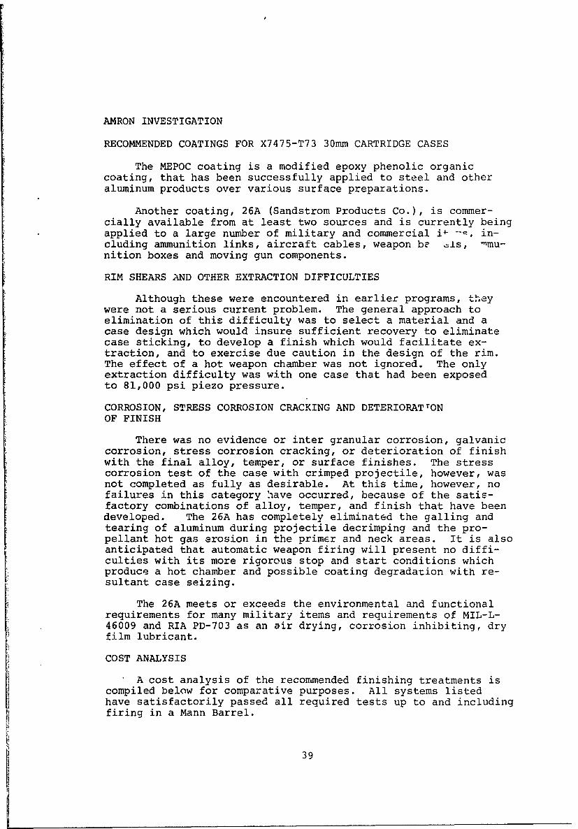
The MEPOC coating is a modified epoxy phenolic organiccoating, that has been successfully applied to steel and otheraluminum products over various surface preparations.
Another coating, 26A (Sandstrom Products Co.), is commer-cially available from at least two sources and is currently beingapplied to a large number of military and commercial i+ ---, in-cluding ammunition links, aircraft cables, weapon be =1s, -mu-nition boxes and moving gun components.
RIM SHEARS AND OTHER EXTRACTION DIFFICULTIES
Although these were encountered in earlier programs, theywere not a serious current problem. The general approach toelimination of this difficulty was to select a material and acase design which would insure sufficient recovery to eliminatecase sticking, to develop a finish which would facilitate ex-traction, and to exercise due caution in the design of the rim.The effect of a hot weapon chamber was not ignored. The onlyextraction difficulty was with one case that had been exposedto 81,000 psi piezo pressure.
CORROSION, STRESS CORROSION CRACKING AND DETERIORATrONOF FINISH
There was no evidence or inter granular corrosion, galvaniccorrosion, stress corrosion cracking, or deterioration of finishwith the final alloy, temper, or surface finishes. The stresscorrosion test of the case with crimped projectile, however, wasnot completed as fully as desirable. At this time, however, nofailures in this category "lave occurred, because of the satis-factory combinations of alloy, temper, and finish that have beendeveloped. The 26A has completely eliminated the galling andtearing of aluminum during projectile decrimping and the pro-pellant hot gas erosion in the primer and neck areas. It is alsoanticipated that automatic weapon firing will present no diffi-culties with its more rigorous stop and start conditions whichproduce a hot chamber and possible coating degradation with re-sultant case seizing.
The 26A meets or exceeds the environmental and functionalrequirements for many military items and requirements of MIL-L-46009 and RIA PD-703 as an air drying, corrosion inhibiting, dryfilm lubricant.
COST ANALYSIS
A cost analysis of the recommended finishing treatments iscompiled below for comparative purposes. All systems listedhave satisfactorily passed all required tests up to and includingfiring in a Mann Barrel.
39

Considered in this analysis were:
1. Surface preparation
2. Substrate
3. Coating
4. Additional surface treatment
5. Top coat
6. Labor
7. Material
8. Equipment
The estimates are based on a production rate (30mm aluminumcartridge cases) of 500,000 per month. At this rate and assum-ing 22 working days of two shifts, each, per month, an average of24 cases per minute must be processed. Obviously, considerableeffort will be required in designing handling equipment for thisvolume of production, and the ultimate costs will depend greatlyon how well that job is done.
In Table III the coating systems and costs were combined onthe same comparative basis. All systems require the same care-ful surface preparation of inhibited alkaline cleaning to re-move fabrication residues, hydrofluoric-nitric acid etching toremove the thermal film and activate the surface, and nitricacid desmutting.
In this process, a unit cost of 1 for cleaning and 2 foretching is assumed. Whether this unit represents 1/4 cent percase, 1/10 cent per case, or something else, will depend on theeffectiveness of the processing equipment design.
On the same scale, anodizing and sealing (0.00015 in. coat-ing with dichromate seal) might be 8 units, chemical conversioncoatinq 2 units, and organic coating 5 units.
40

TABLE III. COATING SYSTEMS AND COSTS ON A COMPARATIVE BASIS
ALCOA SYSTEMS AMRON SYSTEMS1 2 3 4 5 6
Cleaning I&Ol** I&O 1 I&O 1 I&O 1 I&O 1 I&O 1
Etching I&O 1 I&O 1 I&O 1 I&O 1 I&O 1 I&O 1
Desmutting I&O 1 I&O 1 I&O 1 I&O 1 I&O 1 I&O 1
Anodic Oxide I&O 7
Chromium Chromate I&O 2 I&O 2 I&0 2 I&O 2
Dichromate Seal I&O 1
Fluoro-carbon 0 5 0 5
Epoxy Phenolic 0 5
MEPOC 0 5
Epoxy-MOS 2 ____ 0 6 0 7
Total cost Units 16 10 10 10 11 10
Per Case Cost (M) 4.0 2.5 2.5 2.5 2.75 2.5
* Applied to Interior (I) and Outer (0) surfaces.
** Cost unit of each operation
Conversion of these relative values to actual cents per caseis subject to wide variation. It is believed, however, that evenwith low efficiency production facilities, per case coating costsof 4 cents, 2.75 cents and 2.5 cents, respectively, would not beexceeded.
COATING SYSTEMS
1. Alumilite (anodic oxide - .00015 in.) by 15% H2SO,70°F,12 asf (amps/sq.ft.) for 10 minutes, then 10 minutes at 18 OF in5% sodium dichromate, plus McLube 1700 (fluoro-carbon) aerosollubricant.
2. Iridite 14-2 (chromium chromate conversion coating -23 mg/ft 2 ) plus Varcum 5417 (epoxy at .0002 in.) cured at 350 Ffor 30 minutes.
3. Iridite 14-2 (chromium chromate conversion coating -23 mg/ft2) plus McLube 1700 (fluoro-carbon) aerosol lubricant(less than .0001 in.).
41

4. Alodine 1200 (chromium chromate conversion coating) plusMEPOC (Modified epoxy phenolic organic coating).
5. Alodine 1200 (chromium chromate conversion coating) plus26A (modified molybdenum disulfide-epoxy at .0004 - .0006 in.)air-dried or dried at 290 ± 10°F for one minute.
6. Fresh, scrupulously clean bare aluminum plus 26A(modified molybdenum disulfide-epoxy at .0004 - .0006 in.) air-dried or dried at 290 ± 10°F for one minute.
42

SECTION VI
FIRING MECHANISM
GENERAL
The Mann barrel, breech block, and yoke were manufacturedby the Mathewson Tool Company, Orauge, Connecticut, This vendorwas selected because of the total cost of the items and theability of the vendor to deliver these vital components. Thefiring mechanism, as shown in Figure 13, is mounted in the Amronballistic test facility and has the capability to measure coppercrusher and piezo quartz pressures.
BARREL SPECIFICATIONS
Material 4150 Steel
Heat treated to Rockwell "C" 34-36
Length of barrel 95.00 ± .150 in.
Rifling data (from breech):
Chamber 0 to 7.175 in.
Zero twist 7.175 to 10.175 in.
Gain twist 10.175 to 79.425 in.
Constant twist 79.425 to 95.000 in.
Exit angle 80 - 58 minutes
Number of grooves 20
Groove depth .0195 ± .001 in.
Groove width .110 ± .004 in.
Land diameter 1.1835 ± .001 in.
PROBLEM RESOLUTION
Some difficulty was initially encountered in obtaining theproper firing pin energy to ignite the primer. With the inset->tion of a heavy spring on the firing pin, the numerous misfiresencountered during the first tests were eliminated.
GOVERNMENT-FURNISHED EQUIPMENT (BARRELS)
The six gain twist test barrels (FF6357),supplied to Amzonas government furnished equipment,were not used because recham-bering for the RE-5-102 cartridge case would not leave sufficientmaterial for safe test firing. Also, these barrels are approx-imately 50 in. long and are unsatisfactory for this program. TheAir Force suggestion that two barrels be joined together to
43
I

................
* - - -~~~~ . .. ... . . .
. . . .. . . . . . . . . . . . . . . . . . . . .. . .. . . . . . . . . .4
44n

achieve the desired 95 in. length was rejected by the ProgramManager because a projectile would increase its rotational veloc-ity until it reaches the second barrel where there would be areduction ir the rotational velocity due to the reversing of ther ain twist.
45

SECTION VII
TEST FIRING
GENERAL
This section describes the test firing performed. Tables IVthrough VIIIshow the results of the firings under various compara-tive conditions with 5000-grain projectiles.
1. Temperature Preconditioning
The effects produced by varying the preconditioninqtemperature of the assembled round are tabulated below. There isa definite increase in both velocities and pressures as the pre-conditioning temperatures change from - 650 F to 70°F to 165°F.
TABLE IV - Temperature Preconditioning
Number Muzzle Number PressureReadings Velocity1 Readings (Copper)
Cold 13 3420 fps 13 36,298 psi
Ambient 134 3565 143 43,050
Hot 13 3601 13 48,500
iMuzzle Velocity (approximate) = Velocity at 100 feet + 100
2. Hardness
The effects produced by two conditions of mouth hardnesson pressure and velocity provi-d to be indistinguishable as illus-trated below. Once again, all conditions remained constant exceptmouth hardness.
TABLE V - Mouth Hardness
No Pressure(Copper) Muzzle Velocity1
Condition Fired psi %Spread Ft/sec. %Spread
Annealed 10 43,715 9.49 3587 1.06
T-73 29 43,292 8.89 3585 1.89
iMuzzle Velocity (approximate) = Velocity at 100 feet + 100
3. Copper Versus Kistler Pressures
Simultaneous measurements of copper crusher cylinder andKistler Piezo-electric peak pressures were made. The results ofambient temperature firings consistently show Kistler to be 1.25times the copper pressures. Average results follow:
46

- , -' V --'~w _ vT -, v -
TABLE VI Copper vs. Kistler Pressures
No. of YKistler/CopperTemperature Samples Kistler Copper Ratio
Cold 3 43,167 36,140 1.194
Ambient 41 53,439 42,916 1.245
Hot 1 60,400 48,500 1.2474. Coatings
The coatings were compared for possible effects on pres-sure and velocity. All other conditions of projectile and pro-pellant weights, temperature, crimping, and case hardness remainedconstant. There was no significant difference between the var-ious groups.
TABLE VII - Coatings of Fired Cases
Pressure(Copper) Muzzle Velocity1Coatings Plus No. Fired psi %Spread ft/sec. %Spread
Anodized2 C3 44,308 22.00 3522 2.49
Alumilite-McLube 1700 5 42,304 5.15 3564 1.26
Iridite 14-2-McLube 1700 5 41,860 6.09 3560 .45
Alodine-MEPOC 29 43,292 8.89 3585 1.89
Bare Aluminum-26A 5 43,840 4.11 3580 .62
iMuzzle Velocity (Approx.) Velocity at 100 feet + 1002Loaded and Fired with 2300 grains of 1379C(others loadedwith 2350 grains).
3Pressure-average of 12 results; velocity-average of 6results.
5. Current System for Interior Ballistics
Barrel Length: Total - 95 in. Projectile Travel -
87.825 in.
Projectile Weight: 5,000 grains.
Propellant: C.I.L. 137)C, Bulk Density - 0.966 g/ml(244.3 gr/in. 3).
Case Volume: Full - 11.97 in.3 ; With Dummy Projectile -
11.4 in.3.Propellant Weight: Maximum Possible (11.0 in. 3) -
2687 gr., Actual - 2300 gr. (9.41 in. 3), 2325 gr. (9.51 in. 3),and 2350 gr. (9.62 in. 3).
47

6. Summary of Results
The summation of Ballistic Results Table 8 shows thetotal number of cases fired under the various conditions.
'FABLE VIII - Summation n ResultsNo.
No. Muzzle* No. Copper Read- KistlerConditions Readings Velocity Readings Pressure ings Pressure
Dummy Projectile
Room Temperature
2300 gr 1379C 38 3550 fps 40 43,477psi
2315 gr 1379C 1 3523 1 41,320
2325 gr 1379C 17 3539 17 42,382
2350 gr 1379C 78 3579 85 43,003 41 53,427psi
Cold Temperature
2300 gr 1379C 10 3418 10 36,345
2300 gr 1379C 3 3429 3 36,140 3 43,167
Hot Temperature
2300 gr 1379C 12 3593 12 45,450
2350 gr 1379C 1 3696 1 48,500 1 60,500
Room Temperature
1900 gr WC870 1 3444 56,800
2050 gr WC880 2 3497 57,550
1800 gr 1379A 1 -- 35,600
2000 gr 1379A 1 -- 45,650
2225 gr 1379A 2 3696 58,600
2250 gr 1379A 3 3758 62,044
2300 gr 1379A 1 -64,380
*Approximate muzzle velocities were obtained by adding the aver-age distance of velocity determination to the velocity obtainedat that distance (Ex. V100 of 3450 fps plus 100 equals 3550 fps).
7. Time Pressure Curve
The Time Pressure Curve (Figurel4) is a typical curvethat results when piezo quartz pressure in psi is plotted versustime in milliseconds. The significant aspects of these curvesencountered during this developmental program are:
1. 0 to 1 ms - primer ignition
2. 1 to 1.4 ms - primer pressure and start of propellant4ignition
~48

PPOJECTJLE EXIT
I z
0
S r4)
I 9 u
10 Z T
0 0 0 0 0 0 0d0 0 0 0 0 0 OQ 0 0 (:0 0 0 0 0 0
PRESSUPE IN P.S.I.
49

3. 1.4 to 1.6 ms - primer pressure decays, propellant
pressure rises, and projectile movement begins
4. 1.6 to 2.7 ms - propellant pressure rises5. 2.7 to 3.0 ms - propellant burning ceases6. 3.0 to 6.7 ms - propellant pressure decays
7. 6.7 ms - projectile exits barrel muzzle
STUDIES OF METAL EROSION DURING TEST FIRING
The following two reports were made after some incidences ofpropellant gas leaks out of the cartridge case. It should berealized that these were caused by erosion of the metal by thehot propellant gas and not by failure of the metal in the case.
1. Study of Hole in Neck Area
T73 temper with MEPOC coating (not mouth annealed).
a. Holed Case
(1) Neck-shoulder hole (Figure 15)
(a) Only the tadpole's tail eroded through tothe outside; the "body" was physically torn loose due to fusionin "tail" area of the case to the chamber.
(b) Not due to crimping of projectile; appar-ently due to interior metal split in "tail" area with laminationin "body" area of case interior.
(c) Peripherally around the interior of thecase, uneroded pits indicated metal weaknesses, or "dirt" duringforming which came off during cleaning.
(2) Dark streaks from crimp to extractor groove onexterior.
(a) All streaks are inconsistently diagonal withpitted heads toward the case base.
(b) The streaks do not go through to the insideand are still covered with MEPOC.
(c) It appears that "dirt" was present duringfinal forming of the case which came off during cleaning in prep-aration for coating.
b. All other nine cases in this series exhibited pits,with or without streaks, in the interior and exterior to a lesserextent, but no hole occurred.
CONCLUSIONS:
1. The clear MEPOC makes case defects much more visible thanthe Alcoa coatings.
50

I
U0z0U')
"-4
C-,
0r-40
If)r-4
0
z.t
_ LI.I
51

2. The dark streaks on the outside probably form as a resultof turbulence, created by the pits, during the spraying of thecases. This produces a variation in coating texture which is ac-cented by the heat of the curing oven.
3. Pits form due to "dirt" on the case during the final form-ing operations which came off during the cleaning of the case inpreparation for the coating process.
4. An area of metal weakness in the neck-shoulder area al-lowed hot propellant gases to jet through and fuze a spot in thecase neck to the chamber wall which physically tore loose fromthe case when removed from the chamber.
5. This area of metal weakness was likely due to foreignmaterial inclusion in the metal incorporated during the finaldraws.
2. Study of Primer Leak
Components (worse conditions)
a. XM-115 Primers
(1) Unequal length of primer cup sides.
(2) Unfinished primer cup lip (rough).
(3) High hardness of primer cup sides(extra hardD.P.H. 190-Rockwell B-91) with yield strength of 65,000 psi.
(4) Low hardness of primer cup bottom (half hardD.P.H. 100 to 110-Rockwell B-55 to 62).
(5) Voids in exterior side wall of primer cup.
(6) Longitudinal forming-scratches in exterior side
wall of primer cup.
(7) Elliptical circumference (.0009 to .0034 in.).
b. Primer Pocket
(1) Tapered side wall (.0005 to .0015 in.).
(2) Low hardness of side wall (74-76R30T).
(3) Circumferential gaging marks in base metal ofside wall.
(4) Voids in side wall and bottom.
(5) Alodine-coated only (chromium chromate conver-sion coating with no top-coat).
(6) Longitudinal scratches through Alodine intoaluminum in side wall by paint spray conveyor spindle.
52

c. Assembly
(1) Dimensions
(a) Interference on average diameter (.0008 to.0056in)
(b) Crush-up on length (.0015 to.0163 in.).
(c) Seating depth below flush (.002 to .004 in.).
(2) Actions During Priming
(a) Arbor press used for seating.
(b) Rough, hard lip of primer cup machines sidewall of pocket through coating into base metal (longitudinal gougesand some metal particles torn loose).
(c) Hard primer cup side wall assumes taper ofprimer pocket side wall (.0005 to .0015 in.).
(d) Primer sealant used.
(e) No primer staking used.
(f) Pre-conditioned to 1650F before firing.
d. Actions During Firing
(1) Firing pin impacts (soft primer cup indentscrushing and igniting primer mix against anvil).
(2) Primer mix detonates (force loosens and backsout primer against bolt face - .003 to .005 in. protrusion out ofpocket).
(3) Flash of primer mix ignites propellant (hot gasof burning propellant then comes back into primer pocket through
flash hole - piezo quartz at 60.,500 psi).
(4) Hot gases rush through annular arc between twhard primer wall and primer pocket on the loosest side whiere theprimer cup lip is farthest off the pocket bottom and betweenanvil legs.
(5) Erosion of the primer and pocket wall occursalong longitudina, scratches and in areas of turbulent gas washdue to pits and voids (aerodynamic friction raises the.erodinggas temperature from the melting point of aluminum to near theboiling points of both aluminum ane cartridge brass).
(6) The primer wall erodes through from the outsideto the inside (see Figure 16).
(7) The hot propellant gas follows the path of leastresistance across, eroding the bolt face and cartridge case headprotruding beyond the chamber.
53

F'igure 16 Primer Wall Erosion
1%I
Figure 17 Cartridge Case Erosion
54

(8) Only very rarely is burning noted (as evidencedby oxide coating formation).
(9) No damage whatever is done to the flash hole orcase interior walls (see Figure 17).
MISFIRES
There were four instances during this project in which theprimer ignited 8ut the propellant did not. There was one thatoccurred at -65 F and three at 700F. All occurred during thelast week of the contract. Thus, there was insufficient time toexperiment and document the reasons for these malfunctions. Someof the possible contributory causes are:
1. Movement of primer by firing pin impact,
2. Light firing pin impact did not give near-simultaneousignition of primer mix.
3. Temperature differential between 70 F and -65 F, coupledwith differential in thermal expansion between the brass of theprimer, the aluminum of the primer pocket, and the steel of theprojectile, caused the case to "breathe" and draw moisture intothe propellant or primer mix.
4. Cracked primer mix pellet due to inadequate reconsolida-
tion during primer insertion.
5. Underloaded primers.
6. Propellant away from primer at moment of primer ignition.This was done on purpose to three rounds at 700F. to study theeffects produced by excess case volume. Two misfires resulted.
55

SECTION VIII
CONCLUSIONS
GENERAL
The Amron designed cartridge case has been satisfactorilymanufactured and withstood all tests performed under thiscontract.
CASE DESIGN
1. The case designed is capable of withstanding the pres-sure to achieve 3500 ft per second muzzle velocity with a 5000-grain projectile.
2. The overall length of the cartridge case can be reduced
the equivalent of 0.6 cu in. interior volume.
MATERIAL
1. The case material X7475-T73 aluminum alloy is feasihlefor further development in an automatic weapon system providingall surface irregularities are eliminated to prevent turbulenceof hot propellant gases.
2. Raw material should be purchased as plate at properthickness of alloy X7475 - OE4 temper, fine grain size and ofcartridge case quality.
3. Chemical composition limits: X7475-T73:
Silicon Iron Copper Manganese Magnesium
0.10% max. 0.12% max. 1.2 - 1.9% 0.06% max. 1.9 - 2.6%
Chromium Zinc Titanium Others Aluminum
0.18 - 0.25% 5.1 - 6.2% 0.06% max. Each 0.05% RemainderTotal 0.15%
4. Minimum hardness measured at the internal portions ofthe finished cartridge case X7475-T73 head secticn and throughoutthe wall section shall be R3 0T 72 minimum. The mechanical pro-perties of tensile and percent elongation measured at a point 1.5to 2.0 inches from the face of the head section should be:
Ultimate Yield psi % Elongationpsi minimum (.2% offset) (1 in. gage) minimui
minimum
70,000 60,000 u
PROPELLANT
1. The propellant to be used is 1379C from Canadian Indus-tries Limited per Table I. A total of 2350 grains of this pro-pellant is nominally required to drive a 5000-grain projectile to
56

muzzle velocities in excess of 3500 feet per second; 10.1 cubicinches behind the projectile is to be provided for adjustmentof the required propellant with varying conditions.
PRIMER
1. The primer to be used is the production model of theFrankford Arsenal XM-115 percussion primer. This primer is tobe loaded to its full capacity with approximately 4 grains ofprimer composition FA 956. The lip of the primer cup shall bemade smooth and regular. The primer cup itself shall be an-nealed before loading in order to relieve the work-hardening ofthe cup wall.
ASSEMBLY
1. The primer shall be inserted .002 - .006 in. belowflush in the primer pocket, sealed and water-proofed withprimer sealer MIL-L-o10287 sealing lacquer, and staked in theprimer pocket through 3600.
The base of the projectile shall be coated with water-proofing of Ordnance Type III Sealing Compound per MIL-A-82484,inserted into the cartridge case, and have applied a 3600 hy-draulic crimp.
SURFACE FINISH
1. It is believed that the epoxy-phenolic copo]ymer coat-ings over a chromate treatment of the aluminum in an automaticrapid-fire gun system provide all required properties. However,should additional lubricity or higher temperature resistance berequired due to the stop and start conditions of a rapid-firesystem, air drying corrosion inhibiting dry film lubricant perMIL-L-46009 should be used over fresh clean aluminum
57(The reverse of this page is blank)
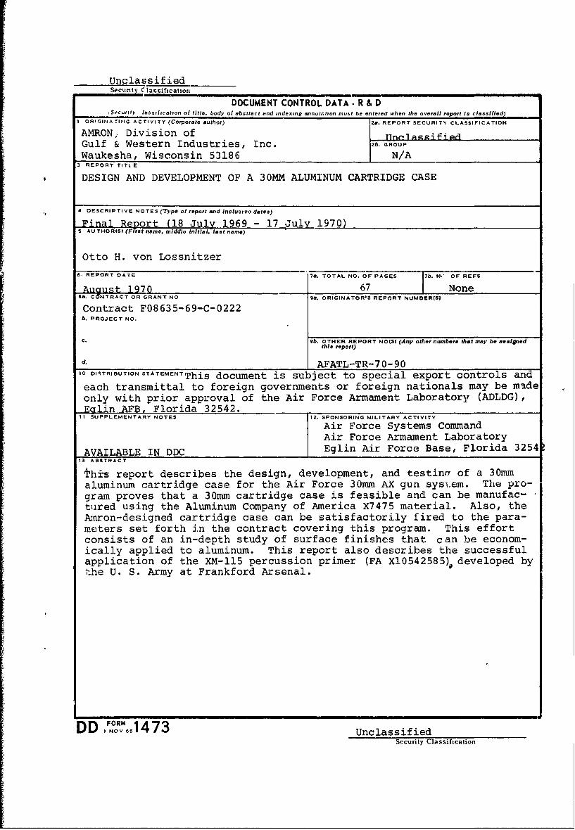
UnclassifiedSecunty C lassification
DOCUMENT CONTROL DATA- R & D(Security lessilhcation ol title, body of abstract and indexing annotation must be entered when the overall report is classified)
I ORIGINATING ACTIVITY (Corporate author) 2a. REPORT SECURITY CLASSIFICATION
AMRON; Division of TTnt1aqifiPGulf & Western Industries, Inc. 2b GROUPWaukesha, Wisconsin 53186 N/A
3 REPORT TITL E
DESIGN AND DEVELOPMENT OF A 30MM ALUMINUM CARTRIDGE CASE
4 DESCRIPTIVE NOTES (Type of report and inclusive dales)
Final Report (18 July 1969 - 17 July 1970)S AU THOR(S) (First name, middle initial, last name)
Otto H. von Lossnitzer
6. REPORT DATE 7a. TOTAL NO. OF PAGES 17b. N.' OF REFS
___ Auust_19767 NoneTa. C5NTRACT OR GRANT NO 9a. ORIGINATOR'S REPORT NUMBER(S)
Contract F08635-69-C-0222b. PROJECT NO.
c. 9b. OTHER REPORT NO(S) (Any other numbere that may be asaljnedthis report)
d. AFATL-TR-70-901o DISTRIBUTION STATEMENT This document is subject to special export controls and
each transmittal to foreign governments or foreign nationals may be madeonly with prior approval of the Air Force Armament Laboratory (ADLDG),Eglin AFB, Florida 32542.
11 SUPPLEMENTARY NOTES 12. SPONSORING MILITARY ACTIVITY
Air Force Systems CommandAir Force Armament Laboratory
AVAILABLE IN DDC Eglin Air Force Base, Florida 3254S- ABSTRACT
±his report describes the design, development, and testina of a 30mmaluminum cartridge case for the Air Force 30mm AX gun sysi.em. The pro-gram proves that a 30mm cartridge case is feasible and can be manufac-tured using the Aluminum Company of America X7475 material. Also, theATnron-designed cartridge case can be satisfactorily fired to the para-meters set forth in the contract covering this program. This effortconsists of an in-depth study of surface finishes that can be econom-ically applied to aluminum. This report also describes the successfulapplication of the XM-115 percussion primer (FA X10542585). developed bythe U. S. Army at Frankford Arsenal.
fFl ORMDDI NOV 651473 UnclassifiedSecurity Classification

k
UnclassifiedSecurity Classification
14.LI AKEY WORDS LINK INK LINK C
ROLE WT ROLE WT ROLE WT
Ammunition
Cartridge case
Aluminum
X7475 alloy aluminum
XM-115 primer
Aluminum surface finishes
CIL 1379C propellant
UnclassifiedSecurity Classification