Embed Size (px)
Citation preview
catch even more fi sh with our new dsp technology!
You’ve probably heard about digital fi sh fi nders, but aren’t quite sure what the difference is. The main difference is the fi ltering capabilities and auto adjustments. Our new DSP (Digital Signal Processing) technology adjusts the picture by fi ltering out items that you don’t need to see, while enhancing the fi sh targets! But even the best digital fi lter won’t help unless you start with a solid base, such as Furuno’s renowned fi sh fi nder technology. Anyone who knows fi shing will tell you that if you want the best fi sh fi nder, you need to go with Furuno. You’ll wonder how you ever managed without it!
NEW! FCV585 - 1kW or 600W
Dual-Frequency 50/200 kHz
8.4˝ Sunlight Viewable LCD
NEW! FCV620 - 600W
Dual-Frequency 50/200 kHz
5.6˝ Sunlight Viewable LCD
Go digital with Furuno and fi nd out!
After 35 years of awards, howcan our Fishfi nders get any better?
Go digital with Furuno and fi nd out!
After 35 years of awards, howcan our Fishfi nders get any better?
RADAR FISH FINDERS SONAR NAVIGATION COMMUNICATION AUTOPILOTS SOFTWARE
The most trusted name in marine electronics!www.Furuno.com
www.Furuno.com
Complete Angler's Guide to Marine Transducers
Furuno off ers a wide range of matched, high perfor-mance transducers for our depth sounders. There are transducers available for virtually every type and size of boat. There are also sensors you can install that will accurately read your boat speed and the surface water temperature. Because there are a number of variables in transducer types that can dramatically aff ect your fi sh fi nder's performance, understanding these variables is the key to selecting the right transducer. This book will help you learn about what makes a transducer ‘tick.’
17
Table of Contents1-3) Theory of Operation
4-5) Mounting Options & Installation tips
6-7) Getting the most out of your Fish Finder
8-10) Transducer Listings
11) Multisensors, Speed and Temperature sensors
12) Smart Sensors
13-15) FAQ's
16) Defi nitions
17) Additional Resources
Additional Resources
www.Furuno.com:Visit our web site at www.Furuno.com for the most up-to-date in-
formation on the entire line of Furuno products. Have a question
that needs an answer? Click on support and browse through our
extensive library of frequently asked questions. You can also ask
our knowledgeable Technical Support staff a question and receive
an answer via e-mail.
www.Airmar.com:AIRMAR Technology Corporation is the leading manufacturer
and OEM supplier of marine transducers, sensors, and instru-
ments for the recreational and professional markets. Visit the
Airmar web site at www.Airmar.com if you are looking for techni-
cal data or detailed specifi cations for a wide variety of transducers
and smart sensors.
Authorized Furuno Dealers:Your local Furuno dealer is perhaps your most valuable resource
when it comes to answering questions about the electronics that
are right for you. To fi nd your nearest Furuno dealer, simply go to
our web site at www.Furuno.com and click on Dealer Locator. En-
ter in your zip code and you will receive a complete list of Furuno
dealers in your area.
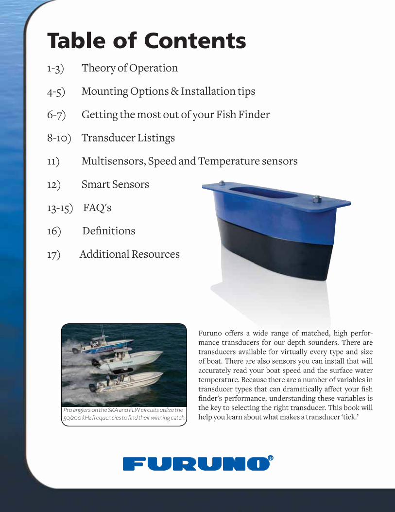
Pro anglers on the SKA and FLW circuits utilize the 50/200 kHz frequencies to fi nd their winning catch.
116
There are a wide variety of transducer options available for Furuno fi sh fi nders, but all of them operate on the same principle. At it’s most basic defi nition, a transducer is a device that takes en-ergy from one source, converts that energy into some other form and then delivers that energy to a target, such as a PA system converting sound from a microphone into electrical signals and then delivering that energy to the speakers. In the case of marine transducers, imagine that the same device can act as both the microphone and the speaker. Electricity from the fi sh fi nder is applied to the transducer, which sends out an acoustic signal - sound waves - into the water column. The transducer receives the refl ected echoes from objects that these sound waves en-counter and they are sent as an electrical signal to your fi sh fi nder. It is the fi sh fi nder's job to process this signal into a picture of the underwa-ter world on your screen.
The Essence of a TransducerThe physical device inside a transducer that creates the sound wave is a piezoceramic disc called the element. The element, when voltage is applied, vibrates - it distorts and reforms its shape in very rapid succession. This vibration oc-curs at a specifi c frequency and creates compres-sion waves, or acoustic energy - sound waves. These waves travel outward from the element in a vaguely cone-shaped pattern and encounter targets along the way.
As this acoustic energy encounters targets such as fi sh or bottom structure, some of the beam will be attenuated (absorbed by the target), some will be refl ected back at the transducer as an echo and some will be scattered. As the refl ected echoes strike the transducer they cause a minus-cule distortion in the shape of the crystal. This distortion of the crystal creates a small fl uctua-tion of voltage, which can be detected and
processed by the fi sh fi nder. The end result is an image on your display.
By measuring the time from when the sound wave is generated to when the return echo is received, we can learn the depth at which a target is encoun-tered. The strength of the refl ected echo can tell us about the size and density of the target.
Some transducers are referred to as single-ele-ment transducers. This means that they contain a single piezoceramic disc that vibrates alternately at 50kHz and 200kHz, utilizing both operating fre-quencies. Furuno off ers a wide range of single-ele-ment transducers that are very popular and carry a low price tag.
When greater performance is desired or required, multiple element transducers are available that can signifi cantly enhance the performance and sensitivity of your fi sh fi nder. A multiple-element transducer is one in which separate elements vibrate individually at their respective frequencies. Some high-end models utilize seven, nine or even fi fteen 50kHz elements along with a large-diameter 200kHz element. The dedicated 200kHz element off ers enhanced sensitivity in shallow water, while the greater surface area of the 50kHz array will receive echoes from deeper water with much more clarity and detail.
How it worksAcoustic: Relating to sound and sound waves.
Acoustic Property: The ability of a material to carry sound through it.
Acoustic Window: That part of the transducer through which the ultrasonic vibrations from the piezoceramic assembly travel to water.
Air Bladder: An organ in a fi sh which allows it to adjust to changes in water pressure at diff erent depths.
Amplitude: The degree of intensity (pressure) of a sound wave. If we could hear the sound wave, amplitude would be it's 'loudness.'
Array: A series of elements in a transducer.
Beamwidth: The diameter of a circle in which 50%-70% of the sound waves emitted by the transducer are concentrated.
Cone Angle: The measurement of beamwidth in degrees. indicates how large an area is covered by a transducer's soundbeam.
dB: Abbreviation for decibel, a unit for measuring the power of a sound wave.
Echosounder: An instrument comprised of a display screen and electronic circuitry used to interpret information from the transducer and display it in a readable format.
Frequency: The number of complete cycles or vibrations that occur within a specifi c time frame, typically one second. Usu-ally measured in Hertz.
Hertz: A measure of one cycle or complete vibration per second.
In-Hull: The method of installing a transducer by attaching it to the inside of the hull.
Multisensor: A combination of three sensing devices (depth, speed and temperature) in a single housing.
Phased Array: A series of piezoceramic elements in a trans-ducer, typically wired to allow them to fi re in time delayed se-quence so the echosounder can electronically steer the array.
Piezoceramic Element: A material made of crystals with posi-tive and negative charges.
Resolution: The sounders ability to show fi ne detail and to discriminate between individual objects.
Sidelobes: Portion of the acoustic image that lies outside of the main sound beam.
Sonar: Derived from the words Sound Navigation and Rang-ing. An apparatus that uses refl ected sound waves to detect and locate objects underwater.
Thru-Hull: A method for installing a transducer through a hole in the hull.
Transducer: A device that changes electrical energy to acous-tic energy and back again.
Transom Mount: A method of installing a transducer on the back (transom) of the boat.
Ultrasonic: Sound waves of high frequency (above 20,000 Hertz) that cannot be heard by humans.
Defi nitions
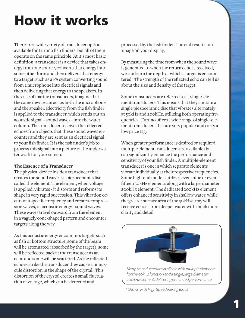
Many transducers are available with multiple elements for the 50kHz function and a single, large diameter 200kHz element, delivering enhanced performance.
* Shown with High Speed Fairing Block
2 15
Frequency demystifi edFrequency refers to the number of sound waves that radiate from a transducer each second. Sound waves are made up of high pressure and low-pres-sure pulses traveling through a given medium. The wavelength of sound is defi ned as the distance between two successive high-pressure pulses or two succes-sive low-pressure pulses. For example, when an electrical pulse is applied to a 200kHz trans-ducer the element vibrates at a frequency of 200,000 cycles per second – that is, 200,000 individ-ual sound waves are transmitted from the element each second. Short-wavelength, high frequency transducers produce sharp, crisp images on the fi sh fi nder display.
Why use two frequencies? For recreational and sportfi sh-ing applications, the 50/200kHz pairing of frequencies off ers an ideal balance of both shallow- and deep-water performance. The 200kHz frequency produces sharp, crisp images in shallow water while 50kHz allows you to “see” much deeper.
Some frequency pairings are more suited to an individual application than others, and for this reason Furuno has always off ered the commercial and serious sport fi sherman a choice when it comes to selecting frequency pairs for a commercial fi sh fi nder. These include 28, 38, 50, 88, 107 and 200kHz.
BeamwidthThe beamwidth of a transducer is a numeric value that describes the eff ective angle of the sound wave. This value is defi ned as the total angle between the points at which the acoustic energy has been re-duced to half its peak value, commonly referred to
as -3dB down points. This value is important because it determines the area in which your fi sh fi nder will be able to “see.”
As the frequency increases the beamwidth will become more narrow, similar to focusing the beam of a fl ashlight. As you adjust the lens, the beam of light focuses and covers a smaller area, deliver-ing more energy on-target. This is more a function of the design of the transducer rather than an inherent property of frequency.
Remember that the lower fre-quency wavelengths “see” deeper in the water column than higher frequency wavelengths, and so a boost in power is not always necessary to detect fi sh in deeper water. The lower in frequency that you go, the deeper the echo sounder will see for the same amount of power. You can also increase the fi sh fi nders detection
range in all frequencies by using a narrower beam transducer. A narrow beam delivers more energy on-target, resulting in stronger echoes, improved target resolution, and the ability to “see” in deeper water.
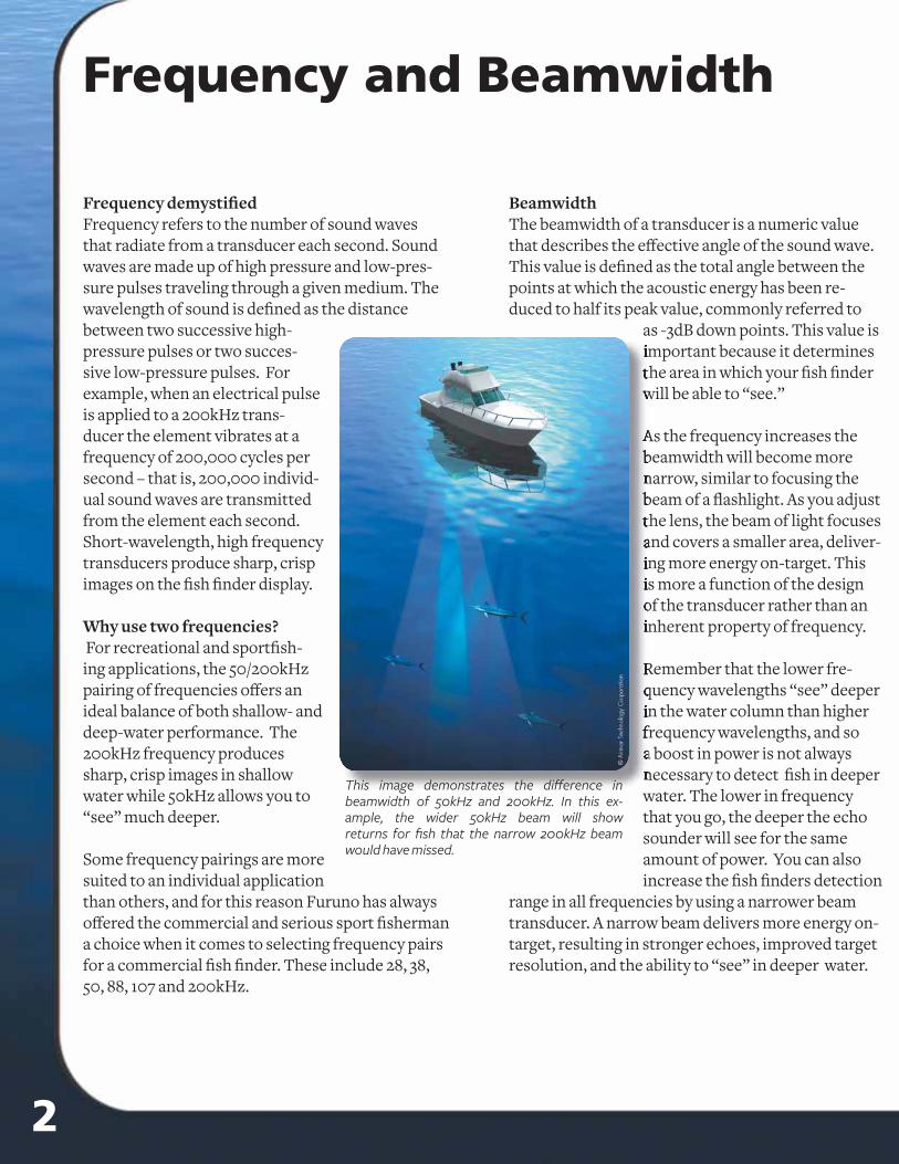
This image demonstrates the diff erence in beamwidth of 50kHz and 200kHz. In this ex-ample, the wider 50kHz beam will show returns for fi sh that the narrow 200kHz beam would have missed.
Q: What is the right transducer for a metal hull?A: Two diff erent metals in contact with each other in water allow electricity to fl ow between them. The resulting decomposition is known as electrolytic corrosion. A plastic transducer housing is the best choice for small aluminum vessels, such as bass boats and runabouts. For larger metal hulls [above 25 feet(8m)], we recommend using a stainless steel housing. However, it must be isolated from the metal hull with a plastic sleeve to prevent electrolytic corrosion. A bedding compound alone will not ensure that electrolytic corrosion is prevented.
A metal transducer must be isolated from a metal hull to avoid electrolytic corrosion that will cause the transducer, propeller and/or hull to decompose. After installation, check that the vessel’s bonding or grounding system is working. Be sure the anodes are suffi cient and in good condition. To verify that your transducer housing is properly isolated from your metal hull, use an ohm meter. Connect one lead of the meter to a spot on the hull that is bare metal - not painted. Connect the second lead to the metal transducer housing-again bare metal. Check several spots for readings. If the ohm meter measures a low resistance, the transducer housing is not suffi ciently isolated, and the isolation procedure needs to be repeated.Q: What type of liquid do I use to fi ll my in-hull base/tank?A: Mineral oil or castor oil should be used to fi ll an in-hull base/tank. These are thick liquids making them less prone to aeration. They do not evaporate as quickly as water and can also handle high power levels. We have also recently approved non-toxic antifreeze/coolant (propylene glycol) as an adequate solution to fi ll an in-hull base/tank. This solution is preferred on installations where the base/tank is installed with silicone.Q: Will a fairing aff ect the performance and top-speed of my boat?A: The size of the transducer will have some aff ect on the top-speed of the boat. However if you use a high-performance fairing, the loss will be minimal. Some people report a decrease of one or two knots. Generally, a 30 foot (10m) or longer boat will see almost no speed loss.Q: Can I cut my transducer cable?A: Yes, the transducer cable can be cut. However, if the transducer came with a connector do not cut it off . The molded on connector is waterproof. You need to cut and splice the cable away from the connector using Airmar's splash-proof Junction Box. The connections will not corrode and the strain relief grommets are water resistant and have excellent cable retention. Please note that cutting the cable or removing the connector, except when using Airmar's junction box, will void the sensor warranty. You can buy a junction box and splice kit from Gem Electronics.
Gem ElectronicsPhone: 843-394-3565 Fax: 843-394-3736.Q: Why does my depth sounder fail when I reach moderate speed? A: If a sounder works fi ne at slow speeds but gradually loses the bottom as the vessels speed increases, it is an indication that aerated water is fl owing over the transducer. Rather than relocate a thru-hull transducer, try installing it with a high-performance fariring. High-performance fairings are designed to improve a sounder's performance at speeds above 17MPH (15kn). It is much longer than its companion transducer. The elongated streamlined shape cuts smoothly through the water, so there is less aerated water fl owing over the transducer's face.Q: Is there an easy way to determine the bottom coverage of my transducer? A: Visit our web site at www.Furuno.com and go to Products - Transducers. Enter your transducer's beam angle from along with a depth into our Transducer Beam Angle Calculator, and it will instantly generate for you an accurate number for bottom coverage.
Frequency and Beamwidth
314
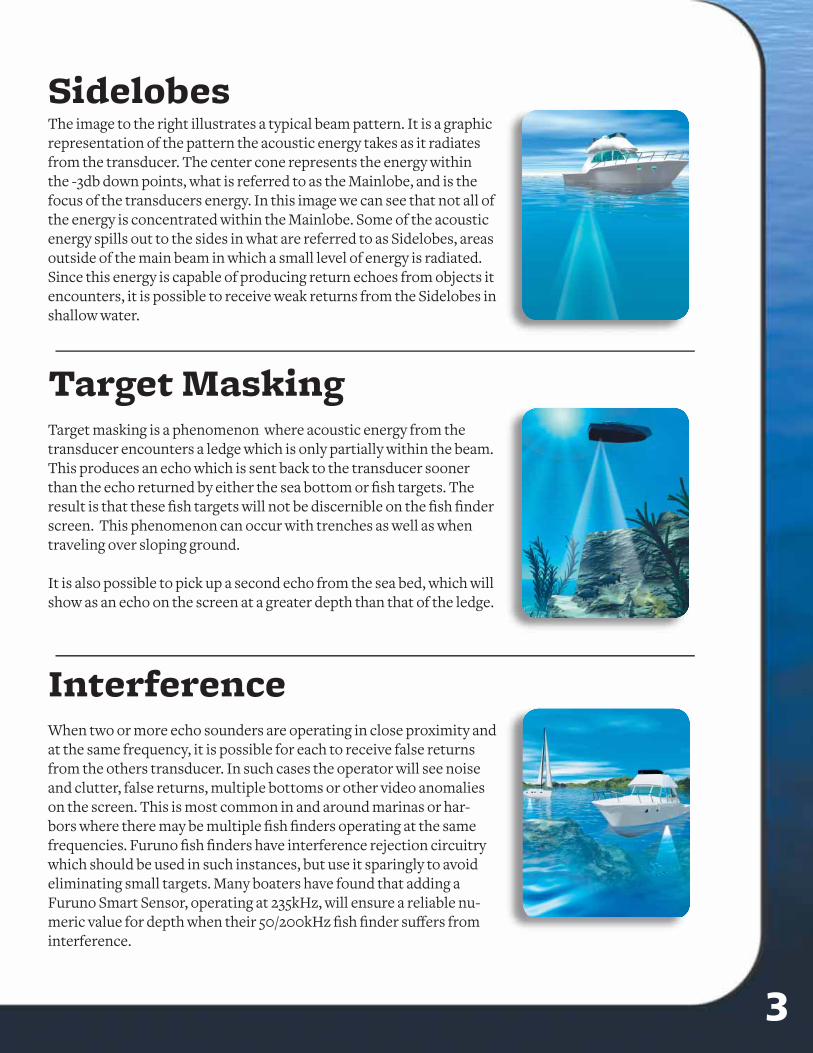
SidelobesThe image to the right illustrates a typical beam pattern. It is a graphic representation of the pattern the acoustic energy takes as it radiates from the transducer. The center cone represents the energy within the -3db down points, what is referred to as the Mainlobe, and is the focus of the transducers energy. In this image we can see that not all of the energy is concentrated within the Mainlobe. Some of the acoustic energy spills out to the sides in what are referred to as Sidelobes, areas outside of the main beam in which a small level of energy is radiated. Since this energy is capable of producing return echoes from objects it encounters, it is possible to receive weak returns from the Sidelobes in shallow water.
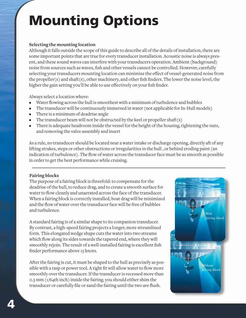
Target masking is a phenomenon where acoustic energy from the transducer encounters a ledge which is only partially within the beam. This produces an echo which is sent back to the transducer sooner than the echo returned by either the sea bottom or fi sh targets. The result is that these fi sh targets will not be discernible on the fi sh fi nder screen. This phenomenon can occur with trenches as well as when traveling over sloping ground.
It is also possible to pick up a second echo from the sea bed, which will show as an echo on the screen at a greater depth than that of the ledge.
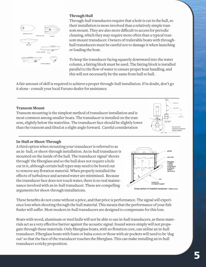
When two or more echo sounders are operating in close proximity and at the same frequency, it is possible for each to receive false returns from the others transducer. In such cases the operator will see noise and clutter, false returns, multiple bottoms or other video anomalies on the screen. This is most common in and around marinas or har-bors where there may be multiple fi sh fi nders operating at the same frequencies. Furuno fi sh fi nders have interference rejection circuitry which should be used in such instances, but use it sparingly to avoid eliminating small targets. Many boaters have found that adding a Furuno Smart Sensor, operating at 235kHz, will ensure a reliable nu-meric value for depth when their 50/200kHz fi sh fi nder suff ers from interference.
Target Masking
Interference
Transducer FAQ'scontinued ...
Q: What is the best place to install a transducer on my hull?A: It is diff erent for each style hull, however there are general guidelines. Choose a location where:
The water fl owing across the hull is smoothest with a minimum amount of bubbles and turbulence (especially at high speeds)The transducer will be in contact with the water continuouslyThere is minimum of vessel generated “noise” from engines, generators, gears, and pumpsThere is minimum deadrise angleThe transducer beam in not blocked by the keel or propeller shaft(s)There is adequate headroom inside the vessel for the height of the housing and tightening the nut(s)
Do not mount the transducer in an area of turbulence or bubbles. There is often turbulence near water intake or discharge openings and behind strakes, fi ttings, or hull irregularities. Do not install behind eroding paint, because it is an indication of turbulence.
•
•••••
Q: What is the relationship between the output wattage of the echosounder and the perfor-mance of the transducer?A: This is similar to an amplifi er and a speaker relationship. The echosounder output wattage must always be less than or equal to the wattage of the transducer. If the echosounder has more output watt-age than the transducer is capable of, the transducer will become damaged.
As far as results are concerned, higher output power equates to greater depth range.
Typically: 600W = 800’- 1200’ Max Depth1KW = 1800’ - 2500’ Max Depth2KW = 2500’ - 4000’ Max Depth
Other factors such as frequency and element/s used also aff ect maximum depth capability.Q: Can transom mount transducers be installed on either the starboard side or port side of the boat?A: We recommend mounting a transom mount transducer on the starboard side on single drive boats. The location should be a minimum of 3” from swing radius of the propeller. Starboard mounting as-sures minimal aeration from the turbulence of the propellers, which can degrade performance.Q: What is the best type of transducer mounting for a stepped hull?A: Choose a thru hull transducer. The steps on the underside of the hull create a lot of aeration. For a transducer to work, it must be mounted just in front of the fi rst step before the source of aeration. Note: A transom mount transducer should never be installed on a stepped hull. When mounted on the transom, the transducer receives all of the aerated water generated by the step(s). A transom mount will perform poorly above 9-12 MPH (8-10kn).
Q: What is a high performance fairing?A: A high-performance fairing improves both a sounder’s and a boat’s performance when traveling at speeds above 17MPH (15kn). A high-performance fairing is much longer than its companion trans-ducer. The elongated streamlined shape cuts smoothly through the water. The results are less aerated water fl owing across the transducer’s face and less boat drag.
We've gathered a list of some of the most frequently asked questions about transducers and provided the answers in this section. If you have a question that is not answered in this book, you can visit us on the web at www.Furuno.com and click on Support. You can browse through answers to questions, or search for your answer by model, topic or keyword. If you can't fi nd the answer you're looking for, you can send an Email directly from our web site to our technical support staff . A knowledgeable technician will respond with your answer, generally within 48 hours.
Q: My transducer needs to be cleaned frequently. Is there any type of paint I can use to prevent barnacles, algae and marine growth from fouling it?A: There are several manufacturers of anti-fouling marine paint. These paints are available from ma-rine supply stores. Furuno recommends spray-on Transducer Paint from Pettit Paints .(www.PettitPaint.com)Q: Do I need a backing block inside the hull?A: Yes, you do need a backing block. After the fairing block is cut, the remaining section becomes the backing block, which provides a level surface for tightening the nuts.Q: I have a transom mount transducer with my sounder. It works, but I know the readings are often wrong.A: The location of the transducer is the most important factor for a successful installation. You can check to see if the transducers location is optimal by performing the following test on the water.
Become familiar with your sounder’s performance at a speed of 4kn (5MPH). Gradually increase the boat speed and watch the gradual decline in performance. If the decline is sudden (not gradual), iden-tify the boat speed at which the onset occurred. Return the boat to this speed. Then gradually increase speed while making moderate turns in both directions. Note if the performance improves while the boat is turning toward the transducer side. If so, the transducer is probably in aerated water or coming out of the water. You probably need to adjust the transducer’s position.
Try the following, one at a time in the order given:
Increase the transducer’s angle in the water. A transducer works better with the trailing edge sitting lower than the leading edge. When the back of the sensor is tilted downward, waterpushes against the face of the transducer. In the case of a multisensor, a downward tilt ensures that the paddlewheel also stays in contact with the water. You may need to add a plastic shim to obtain a suffi cient angle.Move the transducer deeper into the water in increments of 1/8 inch (3mm).On boats capable of speeds above 40 MPH (35kn), move the transducer up on the transom in increments of 1/8 inch (3mm).If all else fails, move the transducer closer to the centerline of the boat. Repair unused screw holes.
•
••
•Q: What type of housing should I choose for my transducer?A: The type of housing you select depends on the hull where it will be installed:
A plastic housing is recommended for fi berglass or metal hulls only. Never install a plastic thru-hull sensor in a wood hull, since swelling of the wood may overstress the plastic and cause a frac-ture.A bronze housing is recommended for fi berglass or wood hulls only. Never install a bronze hous-ing in a metal hull, because electrolytic corrosion will occur.A stainless steel housing is recommended for metal hulls to prevent electrolytic corrosion.Never install a metal housing in a vessel with a positive ground system.
•
•
••
4 13
Mounting Options
Selecting the mounting locationAlthough it falls outside the scope of this guide to describe all of the details of installation, there are some important points that are true for every transducer installation. Acoustic noise is always pres-ent, and these sound waves can interfere with your transducers operation. Ambient (background) noise from sources such as waves, fi sh and other vessels cannot be controlled. However, carefully selecting your transducers mounting location can minimize the eff ect of vessel-generated noise from the propeller(s) and shaft(s), other machinery, and other fi sh fi nders. The lower the noise level, the higher the gain setting you'll be able to use eff ectively on your fi sh fi nder.
Always select a location where:Water fl owing across the hull is smoothest with a minimum of turbulence and bubblesThe transducer will be continuously immersed in water (not applicable for In-Hull models)There is a minimum of deadrise angleThe transducer beam will not be obstructed by the keel or propeller shaft(s)There is adequate headroom inside the vessel for the height of the housing, tightening the nuts, and removing the valve assembly and insert
As a rule, no transducer should be located near a water intake or discharge opening, directly aft of any lifting strakes, steps or other obstructions or irregularities in the hull , or behind eroding paint (an indication of turbulence). The fl ow of water across the transducer face must be as smooth as possible in order to get the best performance while cruising.
•••••
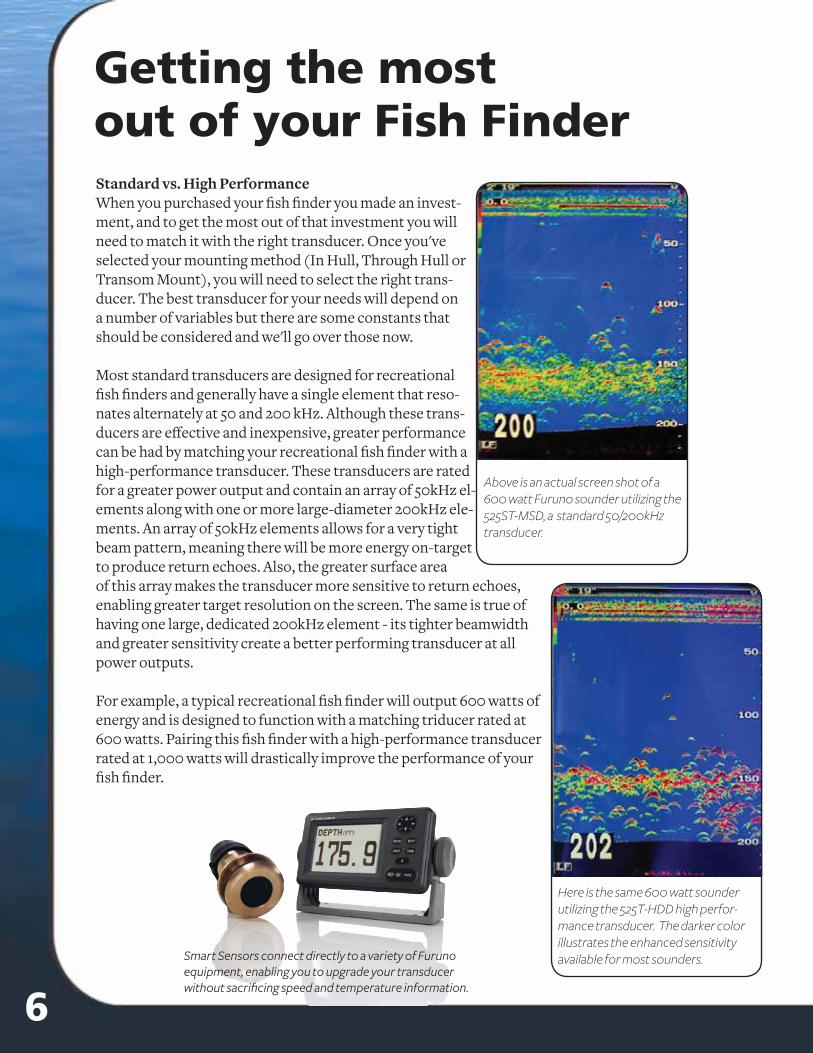
Fairing blocksThe purpose of a fairing block is threefold: to compensate for the deadrise of the hull, to reduce drag, and to create a smooth surface for water to fl ow cleanly and unaerated across the face of the transducer. When a fairing block is correctly installed, boat drag will be minimized and the fl ow of water over the transducer face will be free of bubbles and turbulence.
A standard fairing is of a similar shape to its companion transducer. By contrast, a high-speed fairing projects a longer, more streamlined form. This elongated wedge shape cuts the water into two streams which fl ow along its sides towards the tapered end, where they will smoothly rejoin. The result of a well-installed fairing is excellent fi sh fi nder performance above 15 knots.
After the fairing is cut, it must be shaped to the hull as precisely as pos-sible with a rasp or power tool. A tight fi t will allow water to fl ow more smoothly over the transducer. If the transducer is recessed more than 0.5 mm (1/64th inch) inside the fairing, you should either shim the transducer or carefully fi le or sand the fairing until the two are fl ush.
Withfairing block
Withoutfairing block
Transducer FAQ's
Model Functions Housing Style
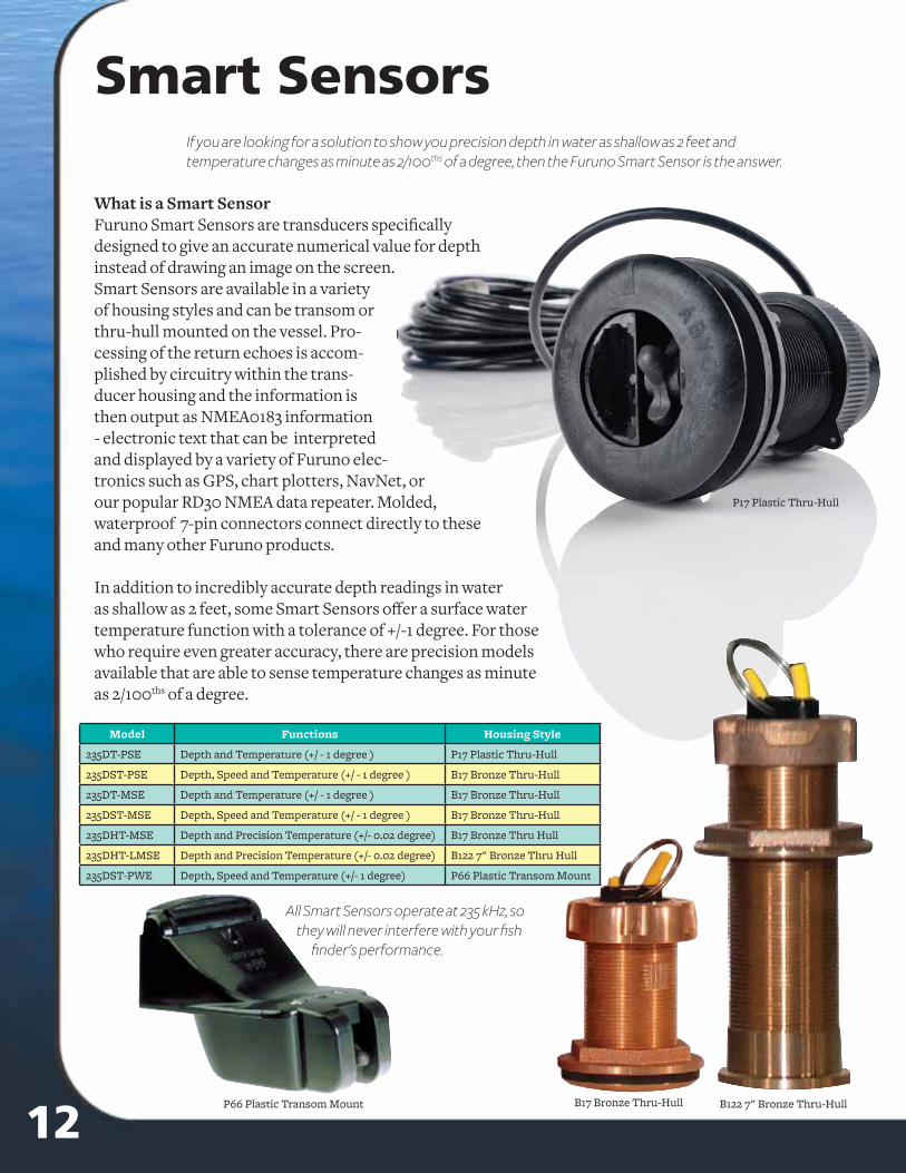
235DT-PSE Depth and Temperature (+/ - 1 degree ) P17 Plastic Thru-Hull
235DST-PSE Depth, Speed and Temperature (+/ - 1 degree ) B17 Bronze Thru-Hull
235DT-MSE Depth and Temperature (+/ - 1 degree ) B17 Bronze Thru-Hull
235DST-MSE Depth, Speed and Temperature (+/ - 1 degree ) B17 Bronze Thru-Hull
235DHT-MSE Depth and Precision Temperature (+/- 0.02 degree) B17 Bronze Thru Hull
235DHT-LMSE Depth and Precision Temperature (+/- 0.02 degree) B122 7" Bronze Thru Hull
235DST-PWE Depth, Speed and Temperature (+/- 1 degree) P66 Plastic Transom Mount
Smart SensorsIf you are looking for a solution to show you precision depth in water as shallow as 2 feet andtemperature changes as minute as 2/100ths of a degree, then the Furuno Smart Sensor is the answer.
What is a Smart SensorFuruno Smart Sensors are transducers specifi cally designed to give an accurate numerical value for depth instead of drawing an image on the screen. Smart Sensors are available in a variety of housing styles and can be transom or thru-hull mounted on the vessel. Pro-cessing of the return echoes is accom-plished by circuitry within the trans-ducer housing and the information is then output as NMEA0183 information - electronic text that can be interpreted and displayed by a variety of Furuno elec-tronics such as GPS, chart plotters, NavNet, or our popular RD30 NMEA data repeater. Molded, waterproof 7-pin connectors connect directly to these and many other Furuno products.
In addition to incredibly accurate depth readings in water as shallow as 2 feet, some Smart Sensors off er a surface water temperature function with a tolerance of +/-1 degree. For those who require even greater accuracy, there are precision models available that are able to sense temperature changes as minute as 2/100ths of a degree.
B122 7" Bronze Thru-Hull
P17 Plastic Thru-Hull
B17 Bronze Thru-Hull
All Smart Sensors operate at 235 kHz, so they will never interfere with your fi sh
fi nder's performance.
P66 Plastic Transom Mount
512
Through HullThrough-hull transducers require that a hole is cut in the hull, so their installation is more involved than a relatively simple tran-som mount. They are also more diffi cult to access for periodic cleaning, which they may require more often than a typical tran-som mount transducer. Owners of trailerable boats with through-hull transducers must be careful not to damage it when launching or loading the boat.
To keep the transducer facing squarely downward into the water column, a fairing block must be used. The fairing block is installed parallel to the fl ow of water to ensure proper boat handling, and this will not necessarily be the same from hull to hull.
A fair amount of skill is required to achieve a proper through-hull installation. If in doubt, don’t go it alone - consult your local Furuno dealer for assistance.
Transom MountTransom mounting is the simplest method of transducer installation and is most common among smaller boats. The transducer is installed on the tran-som, slightly below the waterline. The transducer face should be slightly lower than the transom and tilted at a slight angle forward. Careful consideration
In-Hull or Shoot-ThroughA third option when mounting your transducer is referred to as an in- hull, or shoot-through installation. An in-hull transducer is mounted on the inside of the hull. The transducer signal ‘shoots through’ the fi berglass and so the hull does not require a hole cut in it, although certain hull types may need to be bored out to remove any fl otation material. When properly installed the eff ects of turbulence and aerated water are minimized. Because the transducer face does not touch water, there is no real mainte-nance involved with an in-hull transducer. These are compelling arguments for shoot-through installations.
These benefi ts do not come without a price, and that price is performance. The signal will experi-ence loss when shooting through the hull material. This means that the performance of your fi sh fi nder will suff er. Most modern in-hull transducers are designed to compensate for this loss.
Boats with wood, aluminum or steel hulls will not be able to use in-hull transducers, as these mate-rials act as a very eff ective barrier against the acoustic signal. Sound waves simply will not propa-gate through these materials. Only fi berglass boats, with no fl otation core, can utilize an in-hull transducer. Fiberglass boats with foam or balsa cores or those with air pockets will need to be ‘dug out’ so that the face of the transducer touches the fi berglass. This can make installing an in-hull transducer a tricky proposition.
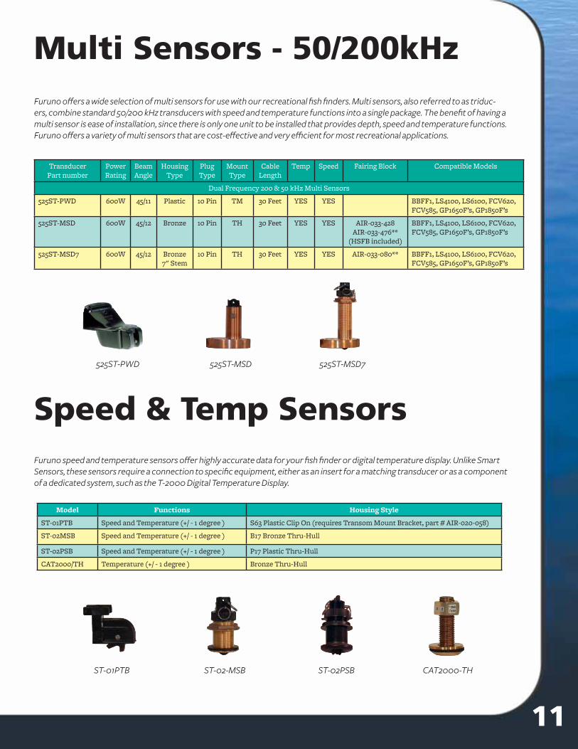
Furuno off ers a wide selection of multi sensors for use with our recreational fi sh fi nders. Multi sensors, also referred to as triduc-ers, combine standard 50/200 kHz transducers with speed and temperature functions into a single package. The benefi t of having a multi sensor is ease of installation, since there is only one unit to be installed that provides depth, speed and temperature functions. Furuno off ers a variety of multi sensors that are cost-eff ective and very effi cient for most recreational applications.
Furuno speed and temperature sensors off er highly accurate data for your fi sh fi nder or digital temperature display. Unlike Smart Sensors, these sensors require a connection to specifi c equipment, either as an insert for a matching transducer or as a component of a dedicated system, such as the T-2000 Digital Temperature Display.
Model Functions Housing Style
ST-01PTB Speed and Temperature (+/ - 1 degree ) S63 Plastic Clip On (requires Transom Mount Bracket, part # AIR-020-058)
ST-02MSB Speed and Temperature (+/ - 1 degree ) B17 Bronze Thru-Hull
ST-02PSB Speed and Temperature (+/ - 1 degree ) P17 Plastic Thru-Hull
CAT2000/TH Temperature (+/ - 1 degree ) Bronze Thru-Hull
Speed & Temp Sensors
Multi Sensors - 50/200kHz
TransducerPart number
Power Rating
BeamAngle
HousingType
PlugType
MountType
CableLength
Temp Speed Fairing Block Compatible Models
Dual Frequency 200 & 50 kHz Multi Sensors
525ST-PWD 600W 45/11 Plastic 10 Pin TM 30 Feet YES YES BBFF1, LS4100, LS6100, FCV620, FCV585, GP1650F’s, GP1850F’s
525ST-MSD 600W 45/12 Bronze 10 Pin TH 30 Feet YES YES AIR-033-428AIR-033-476**
(HSFB included)
BBFF1, LS4100, LS6100, FCV620, FCV585, GP1650F’s, GP1850F’s
525ST-MSD7 600W 45/12 Bronze7" Stem
10 Pin TH 30 Feet YES YES AIR-033-080** BBFF1, LS4100, LS6100, FCV620, FCV585, GP1650F’s, GP1850F’s
ST-01PTB ST-02-MSB ST-02PSB CAT2000-TH
6 11
525ST-PWD 525ST-MSD 525ST-MSD7
Standard vs. High PerformanceWhen you purchased your fi sh fi nder you made an invest-ment, and to get the most out of that investment you will need to match it with the right transducer. Once you've selected your mounting method (In Hull, Through Hull or Transom Mount), you will need to select the right trans-ducer. The best transducer for your needs will depend on a number of variables but there are some constants that should be considered and we'll go over those now.
Most standard transducers are designed for recreational fi sh fi nders and generally have a single element that reso-nates alternately at 50 and 200 kHz. Although these trans-ducers are eff ective and inexpensive, greater performance can be had by matching your recreational fi sh fi nder with a high-performance transducer. These transducers are rated for a greater power output and contain an array of 50kHz el-ements along with one or more large-diameter 200kHz ele-ments. An array of 50kHz elements allows for a very tight beam pattern, meaning there will be more energy on-target to produce return echoes. Also, the greater surface area of this array makes the transducer more sensitive to return echoes, enabling greater target resolution on the screen. The same is true of having one large, dedicated 200kHz element - its tighter beamwidth and greater sensitivity create a better performing transducer at all power outputs.
For example, a typical recreational fi sh fi nder will output 600 watts of energy and is designed to function with a matching triducer rated at 600 watts. Pairing this fi sh fi nder with a high-performance transducer rated at 1,000 watts will drastically improve the performance of your fi sh fi nder.
Getting the most out of your Fish Finder
Here is the same 600 watt sounder utilizing the 525T-HDD high perfor-mance transducer. The darker color illustrates the enhanced sensitivity available for most sounders.
Above is an actual screen shot of a 600 watt Furuno sounder utilizing the 525ST-MSD, a standard 50/200kHz transducer.
Smart Sensors connect directly to a variety of Furuno equipment, enabling you to upgrade your transducer without sacrifi cing speed and temperature information.
Transducers - Other frequencies
TransducerPart number
Frequency Power Rating
BeamAngle
HousingType
PlugType
MountType
CableLength
Compatible Models
CA15F-10 15kHz 2kW 22 x 34 Rubber Coated
NP Tank 15 Meter
BBFF3, FCV292, FCV1100, FCV1200, FCV1200BB, FCV1500
CA15F-4S 15kHz 1kW 28 x 46 Rubber Coated
NP Tank 15 Meter
BBFF3, FCV292, FCV1100, FCV1200, FCV1200BB, FCV1500
CV102 24 kHz 10kW 9 x 10 Rubber Coated
NP Tank 30 Meter
FCV10
CA28-B260 28kHz 1kW 24 x 39 Bronz3 NP TH 10 Meter
BBFF3, FCV292, FCV1100, FCV1200, FCV1200BB, FCV1500
CA28BL-6HR 28kHz 2kW 22 x 32 FRP NP Tank 15 Meter
BBFF3, FCV292, FCV1100, FCV1200, FCV1200BB, FCV1500
CA28BL-12HR 28kHz 3kW 16 x 21.5
FRP NP Tank 15 Meter
BBFF3, FCV292, FCV1100, FCV1200, FCV1200BB, FCV1500
CA28F-18 28kHz 2kW 17 x 18 Rubber Coated
NP Tank 15 Meter
BBFF3, FCV292, FCV1100, FCV1200, FCV1200BB, FCV1500
CA28F-24H 28kHz 3kW 18 x 24 Rubber Coated
NP Tank 15 Meter
BBFF3, FCV292, FCV1100, FCV1200, FCV1200BB, FCV1500
CA28F-38M 28kHz 5kW 14 Rubber Coated
NP Tank 30 Meter
BBFF3, FCV292, FCV1100, FCV1200, FCV1200BB, FCV1500
CA28f-72 28kHz 10kW 12 x 16 Rubber Coated
NP Tank 15 Meter
BBFF3, FCV292, FCV1100, FCV1200, FCV1200BB, FCV1500
CA28F-8 28kHz 1kW 31 x 34 Rubber Coated
NP Tank 15 Meter
BBFF3, FCV292, FCV1100, FCV1200, FCV1200BB, FCV1500
CA33B-6 33kHz Net Sounder Use Only
Rubber Coated
NP Tank 30 Meter
Net Sounder Use Only
CA38BL-9HR 38kHz 2kW 20.5 x 20.5
FRP NP Tank 15 Meter
BBFF3, FCV292, FCV1100, FCV1200, FCV1200BB, FCV1500
CA38BL-15HR 38kHz 3kW 12.5 x 21
FRP NP Tank 15 Meter
BBFF1, LS4100, LS6100, FCV620, FCV585, GP1650F’s, GP1850F’s
CA40B-6B 40kHz Net Sounder Use Only
Rubber Coated
NP Tank 30 Meter
Net Sounder Use Only
CA88F-126H 88kHz 5kW 4 x 5 Rubber Coated
NP Tank 15 Meter
BBFF3, FCV292, FCV1100, FCV1200, FCV1200BB, FCV1500
CA88B-10 88kHz 2kW 8 Rubber Coated
NP Tank 15 Meter
BBFF3, FCV292, FCV1100, FCV1200, FCV1200BB, FCV1500
CA88B-8 88kHz 1kW 11 Rubber Coated
NP Tank 15 Meter
BBFF3, FCV292, FCV1100, FCV1200, FCV1200BB, FCV1500
CA100B-10R 107kHz 3kW 8 x 13 Rubber Coated
NP Tank 10 Meter
BBFF3, FCV292, FCV1100, FCV1200, FCV1200BB, FCV1500
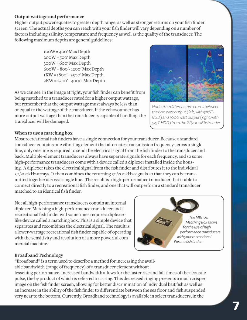
Notice the diff erence in returns between the 600 watt output ( left, with 525ST-MSD ) and 1,000 watt output ( right, with 525T-HDD ) from the GP7000F fi sh fi nder.
710
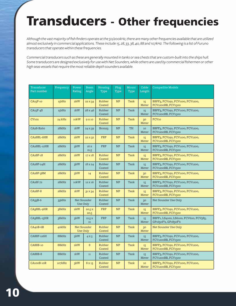
Although the vast majority of fi sh fi nders operate at the 50/200kHz, there are many other frequencies available that are utilized almost exclusively in commercial applications. These include 15, 28, 33, 38, 40, 88 and 107kHz. The following is a list of Furuno transducers that operate within these frequencies.
Commercial transducers such as these are generally mounted in tanks or sea chests that are custom-built into the ships hull. Some transducers are designed exclusively for use with Net Sounders, while others are used by commercial fi shermen or other high seas vessels that require the most reliable depth sounders available.
Output wattage and performanceHigher output power equates to greater depth range, as well as stronger returns on your fi sh fi nder screen. The actual depths you can reach with your fi sh fi nder will vary depending on a number of factors including salinity, temperature and frequency as well as the quality of the transducer. The following maximum depths are general guidelines:
100W = 400' Max Depth 200W = 500' Max Depth 300W = 600' Max Depth 600W = 800'- 1200' Max Depth 1KW = 1800' - 2500' Max Depth 2KW = 2500' - 4000' Max Depth
As we can see in the image at right, your fi sh fi nder can benefi t from being matched to a transducer rated for a higher output wattage, but remember that the output wattage must always be less than or equal to the wattage of the transducer. If the echosounder has more output wattage than the transducer is capable of handling, the transducer will be damaged.
When to use a matching boxMost recreational fi sh fi nders have a single connection for your transducer. Because a standard transducer contains one vibrating element that alternates transmission frequency across a single line, only one line is required to send the electrical signal from the fi sh fi nder to the transducer and back. Multiple-element transducers always have separate signals for each frequency, and so some high-performance transducers come with a device called a diplexer installed inside the hous-ing. A diplexer takes the electrical signal from the fi sh fi nder and distributes it to the individual 50/200kHz arrays. It then combines the returning 50/200kHz signals so that they can be trans-mitted together across a single line. The result is a high-performance transducer that is able to connect directly to a recreational fi sh fi nder, and one that will outperform a standard transducer matched to an identical fi sh fi nder.
Not all high-performance transducers contain an internal diplexer. Matching a high-performance transducer and a recreational fi sh fi nder will sometimes require a diplexer-like device called a matching box. This is a simple device that separates and recombines the electrical signal. The result is a lower-wattage recreational fi sh fi nder capable of operating with the sensitivity and resolution of a more powerful com-mercial machine.
Broadband Technology“Broadband” is a term used to describe a method for increasing the avail-able bandwidth (range of frequency) of a transducer element without lessening performance. Increased bandwidth allows for the faster rise and fall times of the acoustic pulse, the by product of which is referred to as ring. This decreased ringing presents a much crisper image on the fi sh fi nder screen, allowing for better discrimination of individual bait fi sh as well as an increase in the ability of the fi sh fi nder to diff erentiate between the sea fl oor and fi sh suspended very near to the bottom. Currently, Broadband technology is available in select transducers, in the
The MB1100 Matching Box allows
for the use of high performance transducers
with your recreationalFuruno fi sh fi nder.
TransducerPart number
Power Rating
BeamAngle
HousingType
PlugType
MountType
CableLength
Temp Speed Compatible Models
Single Frequency, High Power 200 kHz
CA200B-5 1KW 8.5 Bronze NC TH 50 Feet NO NO BBFF3, FCV292, FCV1100, FCV1200, FCV1200BB, FCV1500
CA200B-5S 1KW 8.5 Rubber NC C, H, T 50 Feet NO NO BBFF3, FCV292, FCV1100, FCV1200, FCV1200BB, FCV1500
CA200B-8B 2KW 5.5 Rubber NC C, H, T 50 Feet NO NO BBFF3, FCV292, FCV1100, FCV1200, FCV1200BB, FCV1500
CA200B-82M 2KW 5.5 Bronze NC TH 50 Feet NO NO BBFF3, FCV292, FCV1100, FCV1200, FCV1200BB, FCV1500
Single Frequency, High Power 50 Khz
CA50B-6B 1KW 28 Rubber NC C, H, T 50 Feet NO NO BBFF3, FCV292, FCV1100, FCV1200, FCV1200BB, FCV1500
CA50B-9B 1KW 12 X 28 Rubber NC C, H, T 50 Feet NO NO BBFF3, FCV292, FCV1100, FCV1200, FCV1200BB, FCV1500
CA50B-92M 1KW 12 X 28 Bronze NC TH 50 Feet NO NO BBFF3, FCV292, FCV1100, FCV1200, FCV1200BB, FCV1500
CA50B-12 2KW 12 X 12 Rubber NC T 50 Feet NO NO BBFF3, FCV292, FCV1100, FCV1200, FCV1200BB, FCV1500
CA50BL-12 2KW 18.5 X 25
Rubber NC T 50 Feet NO NO BBFF3, FCV292, FCV1100, FCV1200, FCV1200BB, FCV1500
CA50F-24H 3KW 9 X 13 Rubber NC T 50 Feet NO NO BBFF3, FCV292, FCV1100, FCV1200, FCV1200BB, FCV1500
CA50BL-24H 3KW 13 X 19 Rubber NC T 50 Feet NO NO BBFF3, FCV292, FCV1100, FCV1200, FCV1200BB, FCV1500
Transducers - 50 or 200 kHzTransducers - 50/200kHzTransducerPart number
Power Rating
BeamAngle
HousingType
PlugType
MountType
CableLength
Temp Fairing Block Compatible Models
Dual Frequency 50 & 200 kHz
520-5MSD 600W 46/10 Bronze 10 Pin TH 30 Feet NO BBFF1, LS4100, LS6100, FCV620, FCV585, GP1650F’s, GP1850F’s
520-5PSD 600W 46/10 Plastic 10 Pin TH 30 Feet NO BBFF1, LS4100, LS6100, FCV620, FCV585, GP1650F’s, GP1850F’s
520-5PWD 600W 46/10 Plastic 10 Pin TM 30 Feet NO BBFF1, LS4100, LS6100, FCV620, FCV585, GP1650F’s, GP1850F’s
520-BLD 600W 45/15 Bronze 10 Pin TH-LP 30 Feet NO BBFF1, LS4100, LS6100, FCV620, FCV585, GP1650F’s, GP1850F’s
520-IHD 600W 45/15 Plastic 10 Pin IH 30 Feet NO BBFF1, LS4100, LS6100, FCV620, FCV585, GP1650F’s, GP1850F’s
520-PLD 600W 45/15 Plastic 10 Pin TH-LP 30 Feet NO BBFF1, LS4100, LS6100, FCV620, FCV585, GP1650F’s, GP1850F’s
520T-HPD 1KW 25/5 Bronze 10 Pin TH 30 Feet YES AIR-033-226,AIR-033-357**
BBFF1, LS4100, LS6100, FCV620, FCV585, GP1650F’s, GP1850F’s
525T-BSD 600W 45/12 Bronze 10 Pin TH 30 Feet YES AIR-033-351AIR-033-352**
BBFF1, LS4100, LS6100, FCV620, FCV585, GP1650F’s, GP1850F’s
525T-LTD/12 600W 20/6Tilted
Element
Bronze 10 Pin TH-LP 30 Feet NO BBFF1, LS4100, LS6100, FCV620, FCV585, GP1650F’s, GP1850F’s
525T-LTD/20 600W 20/6Tilted
Element
Bronze 10 Pin TH-LP 30 Feet NO BBFF1, LS4100, LS6100, FCV620, FCV585, GP1650F’s, GP1850F’s
555-SLD 600W 45/15 SS 10 Pin TH-LP 30 Feet NO BBFF1, LS4100, LS6100, FCV620, FCV585, GP1650F’s, GP1850F’s
CA50/200-12M * 1KW 28/8.5 Bronze NC TH 30 Feet NO BBFF1, LS4100, LS6100, FCV620, FCV585, GP1650F’s, GP1850F’s
CA50/200-1T * 1KW 28/8.5 Rubber NC C, H, T 30 Feet NO BBFF1, LS4100, LS6100, FCV620, FCV585, GP1650F’s, GP1850F’s
526T-HDD **, *** 1KW 20/6 Bronze 10 Pin TH 30 Feet YES AIR-033-391** BBFF1, LS4100, LS6100, FCV620, FCV585, GP1650F’s, GP1850F’s
526T-HDN *, **, *** 1KW 18/9 Bronze NC TH 30 Feet YES AIR-033-391** BBFF1, LS4100, LS6100, FCV620, FCV585, GP1650F’s, GP1850F’s
525T-TMD 1KW 19/6 Valox 10 Pin TM 30 Feet YES BBFF1, LS4100, LS6100, FCV620, FCV585, GP1650F’s, GP1850F’s
527-IHD *** 1KW 19/6 In Hull 10 Pin IH 30 Feet NO BBFF1, LS4100, LS6100, FCV620, FCV585, GP1650F’s, GP1850F’s
526-IHN *, *** 1KW 19/6 In Hull NC IH 30 Feet NO BBFF3, FCV292, FCV1100, FCV1200, FCV1200BB, FCV1500
556T-HDD **, *** 1KW 20/6 SSBroadband
10 Pin TH 30 Feet YES (TBA, included)
BBFF1, LS4100, LS6100, FCV620, FCV585, GP1650F’s, GP1850F’s
555T-HDN *, ** 1KW 20/6 SS NC TH 30 Feet YES (TBA, included)
BBFF3, FCV292, FCV1100, FCV1200, FCV1200BB, FCV1500
CA50/200T-R99 2KW 19/6 Urethane NC IH 30 Feet NO BBFF3, FCV292, FCV1100, FCV1200, FCV1200BB, FCV1500
CA50/200-R199 2KW 9x17/6 Rubber Coated
10 Pin IH 30 Feet YES BBFF3, FCV292, FCV1100, FCV1200, FCV1200BB, FCV1500
* Must connect to MB1100 to use with: BBFF1, LS4100, LS6100, FCV620, FCV585, GP1650F’s, GP1850F’s** High Speed Fairing Block included; *** Broadband Transducer (200 kHz function only)
Legend: W=Watts, KW = Kilowatts, SS = Stainless Steel, NC = No Connector, TH - Thru Hull, TM = Transom Mount, IH = In Hull, LP = Low Profi le,
8 9
CA50/200-R199 In Hull Transducer R199 In-Hull
Transducers - Other frequencies
TransducerPart number
Frequency Power Rating
BeamAngle
HousingType
PlugType
MountType
CableLength
Compatible Models
CA15F-10 15kHz 2kW 22 x 34 Rubber Coated
NP Tank 15 Meter
BBFF3, FCV292, FCV1100, FCV1200, FCV1200BB, FCV1500
CA15F-4S 15kHz 1kW 28 x 46 Rubber Coated
NP Tank 15 Meter
BBFF3, FCV292, FCV1100, FCV1200, FCV1200BB, FCV1500
CV102 24 kHz 10kW 9 x 10 Rubber Coated
NP Tank 30 Meter
FCV10
CA28-B260 28kHz 1kW 24 x 39 Bronz3 NP TH 10 Meter
BBFF3, FCV292, FCV1100, FCV1200, FCV1200BB, FCV1500
CA28BL-6HR 28kHz 2kW 22 x 32 FRP NP Tank 15 Meter
BBFF3, FCV292, FCV1100, FCV1200, FCV1200BB, FCV1500
CA28BL-12HR 28kHz 3kW 16 x 21.5
FRP NP Tank 15 Meter
BBFF3, FCV292, FCV1100, FCV1200, FCV1200BB, FCV1500
CA28F-18 28kHz 2kW 17 x 18 Rubber Coated
NP Tank 15 Meter
BBFF3, FCV292, FCV1100, FCV1200, FCV1200BB, FCV1500
CA28F-24H 28kHz 3kW 18 x 24 Rubber Coated
NP Tank 15 Meter
BBFF3, FCV292, FCV1100, FCV1200, FCV1200BB, FCV1500
CA28F-38M 28kHz 5kW 14 Rubber Coated
NP Tank 30 Meter
BBFF3, FCV292, FCV1100, FCV1200, FCV1200BB, FCV1500
CA28f-72 28kHz 10kW 12 x 16 Rubber Coated
NP Tank 15 Meter
BBFF3, FCV292, FCV1100, FCV1200, FCV1200BB, FCV1500
CA28F-8 28kHz 1kW 31 x 34 Rubber Coated
NP Tank 15 Meter
BBFF3, FCV292, FCV1100, FCV1200, FCV1200BB, FCV1500
CA33B-6 33kHz Net Sounder Use Only
Rubber Coated
NP Tank 30 Meter
Net Sounder Use Only
CA38BL-9HR 38kHz 2kW 20.5 x 20.5
FRP NP Tank 15 Meter
BBFF3, FCV292, FCV1100, FCV1200, FCV1200BB, FCV1500
CA38BL-15HR 38kHz 3kW 12.5 x 21
FRP NP Tank 15 Meter
BBFF1, LS4100, LS6100, FCV620, FCV585, GP1650F’s, GP1850F’s
CA40B-6B 40kHz Net Sounder Use Only
Rubber Coated
NP Tank 30 Meter
Net Sounder Use Only
CA88F-126H 88kHz 5kW 4 x 5 Rubber Coated
NP Tank 15 Meter
BBFF3, FCV292, FCV1100, FCV1200, FCV1200BB, FCV1500
CA88B-10 88kHz 2kW 8 Rubber Coated
NP Tank 15 Meter
BBFF3, FCV292, FCV1100, FCV1200, FCV1200BB, FCV1500
CA88B-8 88kHz 1kW 11 Rubber Coated
NP Tank 15 Meter
BBFF3, FCV292, FCV1100, FCV1200, FCV1200BB, FCV1500
CA100B-10R 107kHz 3kW 8 x 13 Rubber Coated
NP Tank 10 Meter
BBFF3, FCV292, FCV1100, FCV1200, FCV1200BB, FCV1500
Notice the diff erence in returns between the 600 watt output ( left, with 525ST-MSD ) and 1,000 watt output ( right, with 525T-HDD ) from the GP7000F fi sh fi nder.
710
Although the vast majority of fi sh fi nders operate at the 50/200kHz, there are many other frequencies available that are utilized almost exclusively in commercial applications. These include 15, 28, 33, 38, 40, 88 and 107kHz. The following is a list of Furuno transducers that operate within these frequencies.
Commercial transducers such as these are generally mounted in tanks or sea chests that are custom-built into the ships hull. Some transducers are designed exclusively for use with Net Sounders, while others are used by commercial fi shermen or other high seas vessels that require the most reliable depth sounders available.
Output wattage and performanceHigher output power equates to greater depth range, as well as stronger returns on your fi sh fi nder screen. The actual depths you can reach with your fi sh fi nder will vary depending on a number of factors including salinity, temperature and frequency as well as the quality of the transducer. The following maximum depths are general guidelines:
100W = 400' Max Depth 200W = 500' Max Depth 300W = 600' Max Depth 600W = 800'- 1200' Max Depth 1KW = 1800' - 2500' Max Depth 2KW = 2500' - 4000' Max Depth
As we can see in the image at right, your fi sh fi nder can benefi t from being matched to a transducer rated for a higher output wattage, but remember that the output wattage must always be less than or equal to the wattage of the transducer. If the echosounder has more output wattage than the transducer is capable of handling, the transducer will be damaged.
When to use a matching boxMost recreational fi sh fi nders have a single connection for your transducer. Because a standard transducer contains one vibrating element that alternates transmission frequency across a single line, only one line is required to send the electrical signal from the fi sh fi nder to the transducer and back. Multiple-element transducers always have separate signals for each frequency, and so some high-performance transducers come with a device called a diplexer installed inside the hous-ing. A diplexer takes the electrical signal from the fi sh fi nder and distributes it to the individual 50/200kHz arrays. It then combines the returning 50/200kHz signals so that they can be trans-mitted together across a single line. The result is a high-performance transducer that is able to connect directly to a recreational fi sh fi nder, and one that will outperform a standard transducer matched to an identical fi sh fi nder.
Not all high-performance transducers contain an internal diplexer. Matching a high-performance transducer and a recreational fi sh fi nder will sometimes require a diplexer-like device called a matching box. This is a simple device that separates and recombines the electrical signal. The result is a lower-wattage recreational fi sh fi nder capable of operating with the sensitivity and resolution of a more powerful com-mercial machine.
Broadband Technology“Broadband” is a term used to describe a method for increasing the avail-able bandwidth (range of frequency) of a transducer element without lessening performance. Increased bandwidth allows for the faster rise and fall times of the acoustic pulse, the by product of which is referred to as ring. This decreased ringing presents a much crisper image on the fi sh fi nder screen, allowing for better discrimination of individual bait fi sh as well as an increase in the ability of the fi sh fi nder to diff erentiate between the sea fl oor and fi sh suspended very near to the bottom. Currently, Broadband technology is available in select transducers, in the
The MB1100 Matching Box allows
for the use of high performance transducers
with your recreationalFuruno fi sh fi nder.
Furuno off ers a wide selection of multi sensors for use with our recreational fi sh fi nders. Multi sensors, also referred to as triduc-ers, combine standard 50/200 kHz transducers with speed and temperature functions into a single package. The benefi t of having a multi sensor is ease of installation, since there is only one unit to be installed that provides depth, speed and temperature functions. Furuno off ers a variety of multi sensors that are cost-eff ective and very effi cient for most recreational applications.
Furuno speed and temperature sensors off er highly accurate data for your fi sh fi nder or digital temperature display. Unlike Smart Sensors, these sensors require a connection to specifi c equipment, either as an insert for a matching transducer or as a component of a dedicated system, such as the T-2000 Digital Temperature Display.
Model Functions Housing Style
ST-01PTB Speed and Temperature (+/ - 1 degree ) S63 Plastic Clip On (requires Transom Mount Bracket, part # AIR-020-058)
ST-02MSB Speed and Temperature (+/ - 1 degree ) B17 Bronze Thru-Hull
ST-02PSB Speed and Temperature (+/ - 1 degree ) P17 Plastic Thru-Hull
CAT2000/TH Temperature (+/ - 1 degree ) Bronze Thru-Hull
Speed & Temp Sensors
Multi Sensors - 50/200kHz
TransducerPart number
Power Rating
BeamAngle
HousingType
PlugType
MountType
CableLength
Temp Speed Fairing Block Compatible Models
Dual Frequency 200 & 50 kHz Multi Sensors
525ST-PWD 600W 45/11 Plastic 10 Pin TM 30 Feet YES YES BBFF1, LS4100, LS6100, FCV620, FCV585, GP1650F’s, GP1850F’s
525ST-MSD 600W 45/12 Bronze 10 Pin TH 30 Feet YES YES AIR-033-428AIR-033-476**
(HSFB included)
BBFF1, LS4100, LS6100, FCV620, FCV585, GP1650F’s, GP1850F’s
525ST-MSD7 600W 45/12 Bronze7" Stem
10 Pin TH 30 Feet YES YES AIR-033-080** BBFF1, LS4100, LS6100, FCV620, FCV585, GP1650F’s, GP1850F’s
ST-01PTB ST-02-MSB ST-02PSB CAT2000-TH
6 11
525ST-PWD 525ST-MSD 525ST-MSD7
Standard vs. High PerformanceWhen you purchased your fi sh fi nder you made an invest-ment, and to get the most out of that investment you will need to match it with the right transducer. Once you've selected your mounting method (In Hull, Through Hull or Transom Mount), you will need to select the right trans-ducer. The best transducer for your needs will depend on a number of variables but there are some constants that should be considered and we'll go over those now.
Most standard transducers are designed for recreational fi sh fi nders and generally have a single element that reso-nates alternately at 50 and 200 kHz. Although these trans-ducers are eff ective and inexpensive, greater performance can be had by matching your recreational fi sh fi nder with a high-performance transducer. These transducers are rated for a greater power output and contain an array of 50kHz el-ements along with one or more large-diameter 200kHz ele-ments. An array of 50kHz elements allows for a very tight beam pattern, meaning there will be more energy on-target to produce return echoes. Also, the greater surface area of this array makes the transducer more sensitive to return echoes, enabling greater target resolution on the screen. The same is true of having one large, dedicated 200kHz element - its tighter beamwidth and greater sensitivity create a better performing transducer at all power outputs.
For example, a typical recreational fi sh fi nder will output 600 watts of energy and is designed to function with a matching triducer rated at 600 watts. Pairing this fi sh fi nder with a high-performance transducer rated at 1,000 watts will drastically improve the performance of your fi sh fi nder.
Getting the most out of your Fish Finder
Here is the same 600 watt sounder utilizing the 525T-HDD high perfor-mance transducer. The darker color illustrates the enhanced sensitivity available for most sounders.
Above is an actual screen shot of a 600 watt Furuno sounder utilizing the 525ST-MSD, a standard 50/200kHz transducer.
Smart Sensors connect directly to a variety of Furuno equipment, enabling you to upgrade your transducer without sacrifi cing speed and temperature information.
Model Functions Housing Style
235DT-PSE Depth and Temperature (+/ - 1 degree ) P17 Plastic Thru-Hull
235DST-PSE Depth, Speed and Temperature (+/ - 1 degree ) B17 Bronze Thru-Hull
235DT-MSE Depth and Temperature (+/ - 1 degree ) B17 Bronze Thru-Hull
235DST-MSE Depth, Speed and Temperature (+/ - 1 degree ) B17 Bronze Thru-Hull
235DHT-MSE Depth and Precision Temperature (+/- 0.02 degree) B17 Bronze Thru Hull
235DHT-LMSE Depth and Precision Temperature (+/- 0.02 degree) B122 7" Bronze Thru Hull
235DST-PWE Depth, Speed and Temperature (+/- 1 degree) P66 Plastic Transom Mount
Smart SensorsIf you are looking for a solution to show you precision depth in water as shallow as 2 feet andtemperature changes as minute as 2/100ths of a degree, then the Furuno Smart Sensor is the answer.
What is a Smart SensorFuruno Smart Sensors are transducers specifi cally designed to give an accurate numerical value for depth instead of drawing an image on the screen. Smart Sensors are available in a variety of housing styles and can be transom or thru-hull mounted on the vessel. Pro-cessing of the return echoes is accom-plished by circuitry within the trans-ducer housing and the information is then output as NMEA0183 information - electronic text that can be interpreted and displayed by a variety of Furuno elec-tronics such as GPS, chart plotters, NavNet, or our popular RD30 NMEA data repeater. Molded, waterproof 7-pin connectors connect directly to these and many other Furuno products.
In addition to incredibly accurate depth readings in water as shallow as 2 feet, some Smart Sensors off er a surface water temperature function with a tolerance of +/-1 degree. For those who require even greater accuracy, there are precision models available that are able to sense temperature changes as minute as 2/100ths of a degree.
B122 7" Bronze Thru-Hull
P17 Plastic Thru-Hull
B17 Bronze Thru-Hull
All Smart Sensors operate at 235 kHz, so they will never interfere with your fi sh
fi nder's performance.
P66 Plastic Transom Mount
512
Through HullThrough-hull transducers require that a hole is cut in the hull, so their installation is more involved than a relatively simple tran-som mount. They are also more diffi cult to access for periodic cleaning, which they may require more often than a typical tran-som mount transducer. Owners of trailerable boats with through-hull transducers must be careful not to damage it when launching or loading the boat.
To keep the transducer facing squarely downward into the water column, a fairing block must be used. The fairing block is installed parallel to the fl ow of water to ensure proper boat handling, and this will not necessarily be the same from hull to hull.
A fair amount of skill is required to achieve a proper through-hull installation. If in doubt, don’t go it alone - consult your local Furuno dealer for assistance.
Transom MountTransom mounting is the simplest method of transducer installation and is most common among smaller boats. The transducer is installed on the tran-som, slightly below the waterline. The transducer face should be slightly lower than the transom and tilted at a slight angle forward. Careful consideration
In-Hull or Shoot-ThroughA third option when mounting your transducer is referred to as an in- hull, or shoot-through installation. An in-hull transducer is mounted on the inside of the hull. The transducer signal ‘shoots through’ the fi berglass and so the hull does not require a hole cut in it, although certain hull types may need to be bored out to remove any fl otation material. When properly installed the eff ects of turbulence and aerated water are minimized. Because the transducer face does not touch water, there is no real mainte-nance involved with an in-hull transducer. These are compelling arguments for shoot-through installations.
These benefi ts do not come without a price, and that price is performance. The signal will experi-ence loss when shooting through the hull material. This means that the performance of your fi sh fi nder will suff er. Most modern in-hull transducers are designed to compensate for this loss.
Boats with wood, aluminum or steel hulls will not be able to use in-hull transducers, as these mate-rials act as a very eff ective barrier against the acoustic signal. Sound waves simply will not propa-gate through these materials. Only fi berglass boats, with no fl otation core, can utilize an in-hull transducer. Fiberglass boats with foam or balsa cores or those with air pockets will need to be ‘dug out’ so that the face of the transducer touches the fi berglass. This can make installing an in-hull transducer a tricky proposition.
We've gathered a list of some of the most frequently asked questions about transducers and provided the answers in this section. If you have a question that is not answered in this book, you can visit us on the web at www.Furuno.com and click on Support. You can browse through answers to questions, or search for your answer by model, topic or keyword. If you can't fi nd the answer you're looking for, you can send an Email directly from our web site to our technical support staff . A knowledgeable technician will respond with your answer, generally within 48 hours.
Q: My transducer needs to be cleaned frequently. Is there any type of paint I can use to prevent barnacles, algae and marine growth from fouling it?A: There are several manufacturers of anti-fouling marine paint. These paints are available from ma-rine supply stores. Furuno recommends spray-on Transducer Paint from Pettit Paints .(www.PettitPaint.com)Q: Do I need a backing block inside the hull?A: Yes, you do need a backing block. After the fairing block is cut, the remaining section becomes the backing block, which provides a level surface for tightening the nuts.Q: I have a transom mount transducer with my sounder. It works, but I know the readings are often wrong.A: The location of the transducer is the most important factor for a successful installation. You can check to see if the transducers location is optimal by performing the following test on the water.
Become familiar with your sounder’s performance at a speed of 4kn (5MPH). Gradually increase the boat speed and watch the gradual decline in performance. If the decline is sudden (not gradual), iden-tify the boat speed at which the onset occurred. Return the boat to this speed. Then gradually increase speed while making moderate turns in both directions. Note if the performance improves while the boat is turning toward the transducer side. If so, the transducer is probably in aerated water or coming out of the water. You probably need to adjust the transducer’s position.
Try the following, one at a time in the order given:
Increase the transducer’s angle in the water. A transducer works better with the trailing edge sitting lower than the leading edge. When the back of the sensor is tilted downward, waterpushes against the face of the transducer. In the case of a multisensor, a downward tilt ensures that the paddlewheel also stays in contact with the water. You may need to add a plastic shim to obtain a suffi cient angle.Move the transducer deeper into the water in increments of 1/8 inch (3mm).On boats capable of speeds above 40 MPH (35kn), move the transducer up on the transom in increments of 1/8 inch (3mm).If all else fails, move the transducer closer to the centerline of the boat. Repair unused screw holes.
•
••
•Q: What type of housing should I choose for my transducer?A: The type of housing you select depends on the hull where it will be installed:
A plastic housing is recommended for fi berglass or metal hulls only. Never install a plastic thru-hull sensor in a wood hull, since swelling of the wood may overstress the plastic and cause a frac-ture.A bronze housing is recommended for fi berglass or wood hulls only. Never install a bronze hous-ing in a metal hull, because electrolytic corrosion will occur.A stainless steel housing is recommended for metal hulls to prevent electrolytic corrosion.Never install a metal housing in a vessel with a positive ground system.
•
•
••
4 13
Mounting Options
Selecting the mounting locationAlthough it falls outside the scope of this guide to describe all of the details of installation, there are some important points that are true for every transducer installation. Acoustic noise is always pres-ent, and these sound waves can interfere with your transducers operation. Ambient (background) noise from sources such as waves, fi sh and other vessels cannot be controlled. However, carefully selecting your transducers mounting location can minimize the eff ect of vessel-generated noise from the propeller(s) and shaft(s), other machinery, and other fi sh fi nders. The lower the noise level, the higher the gain setting you'll be able to use eff ectively on your fi sh fi nder.
Always select a location where:Water fl owing across the hull is smoothest with a minimum of turbulence and bubblesThe transducer will be continuously immersed in water (not applicable for In-Hull models)There is a minimum of deadrise angleThe transducer beam will not be obstructed by the keel or propeller shaft(s)There is adequate headroom inside the vessel for the height of the housing, tightening the nuts, and removing the valve assembly and insert
As a rule, no transducer should be located near a water intake or discharge opening, directly aft of any lifting strakes, steps or other obstructions or irregularities in the hull , or behind eroding paint (an indication of turbulence). The fl ow of water across the transducer face must be as smooth as possible in order to get the best performance while cruising.
•••••
Fairing blocksThe purpose of a fairing block is threefold: to compensate for the deadrise of the hull, to reduce drag, and to create a smooth surface for water to fl ow cleanly and unaerated across the face of the transducer. When a fairing block is correctly installed, boat drag will be minimized and the fl ow of water over the transducer face will be free of bubbles and turbulence.
A standard fairing is of a similar shape to its companion transducer. By contrast, a high-speed fairing projects a longer, more streamlined form. This elongated wedge shape cuts the water into two streams which fl ow along its sides towards the tapered end, where they will smoothly rejoin. The result of a well-installed fairing is excellent fi sh fi nder performance above 15 knots.
After the fairing is cut, it must be shaped to the hull as precisely as pos-sible with a rasp or power tool. A tight fi t will allow water to fl ow more smoothly over the transducer. If the transducer is recessed more than 0.5 mm (1/64th inch) inside the fairing, you should either shim the transducer or carefully fi le or sand the fairing until the two are fl ush.
Withfairing block
Withoutfairing block
Transducer FAQ's
314
SidelobesThe image to the right illustrates a typical beam pattern. It is a graphic representation of the pattern the acoustic energy takes as it radiates from the transducer. The center cone represents the energy within the -3db down points, what is referred to as the Mainlobe, and is the focus of the transducers energy. In this image we can see that not all of the energy is concentrated within the Mainlobe. Some of the acoustic energy spills out to the sides in what are referred to as Sidelobes, areas outside of the main beam in which a small level of energy is radiated. Since this energy is capable of producing return echoes from objects it encounters, it is possible to receive weak returns from the Sidelobes in shallow water.
Target masking is a phenomenon where acoustic energy from the transducer encounters a ledge which is only partially within the beam. This produces an echo which is sent back to the transducer sooner than the echo returned by either the sea bottom or fi sh targets. The result is that these fi sh targets will not be discernible on the fi sh fi nder screen. This phenomenon can occur with trenches as well as when traveling over sloping ground.
It is also possible to pick up a second echo from the sea bed, which will show as an echo on the screen at a greater depth than that of the ledge.
When two or more echo sounders are operating in close proximity and at the same frequency, it is possible for each to receive false returns from the others transducer. In such cases the operator will see noise and clutter, false returns, multiple bottoms or other video anomalies on the screen. This is most common in and around marinas or har-bors where there may be multiple fi sh fi nders operating at the same frequencies. Furuno fi sh fi nders have interference rejection circuitry which should be used in such instances, but use it sparingly to avoid eliminating small targets. Many boaters have found that adding a Furuno Smart Sensor, operating at 235kHz, will ensure a reliable nu-meric value for depth when their 50/200kHz fi sh fi nder suff ers from interference.
Target Masking
Interference
Transducer FAQ'scontinued ...
Q: What is the best place to install a transducer on my hull?A: It is diff erent for each style hull, however there are general guidelines. Choose a location where:
The water fl owing across the hull is smoothest with a minimum amount of bubbles and turbulence (especially at high speeds)The transducer will be in contact with the water continuouslyThere is minimum of vessel generated “noise” from engines, generators, gears, and pumpsThere is minimum deadrise angleThe transducer beam in not blocked by the keel or propeller shaft(s)There is adequate headroom inside the vessel for the height of the housing and tightening the nut(s)
Do not mount the transducer in an area of turbulence or bubbles. There is often turbulence near water intake or discharge openings and behind strakes, fi ttings, or hull irregularities. Do not install behind eroding paint, because it is an indication of turbulence.
•
•••••
Q: What is the relationship between the output wattage of the echosounder and the perfor-mance of the transducer?A: This is similar to an amplifi er and a speaker relationship. The echosounder output wattage must always be less than or equal to the wattage of the transducer. If the echosounder has more output watt-age than the transducer is capable of, the transducer will become damaged.
As far as results are concerned, higher output power equates to greater depth range.
Typically: 600W = 800’- 1200’ Max Depth1KW = 1800’ - 2500’ Max Depth2KW = 2500’ - 4000’ Max Depth
Other factors such as frequency and element/s used also aff ect maximum depth capability.Q: Can transom mount transducers be installed on either the starboard side or port side of the boat?A: We recommend mounting a transom mount transducer on the starboard side on single drive boats. The location should be a minimum of 3” from swing radius of the propeller. Starboard mounting as-sures minimal aeration from the turbulence of the propellers, which can degrade performance.Q: What is the best type of transducer mounting for a stepped hull?A: Choose a thru hull transducer. The steps on the underside of the hull create a lot of aeration. For a transducer to work, it must be mounted just in front of the fi rst step before the source of aeration. Note: A transom mount transducer should never be installed on a stepped hull. When mounted on the transom, the transducer receives all of the aerated water generated by the step(s). A transom mount will perform poorly above 9-12 MPH (8-10kn).
Q: What is a high performance fairing?A: A high-performance fairing improves both a sounder’s and a boat’s performance when traveling at speeds above 17MPH (15kn). A high-performance fairing is much longer than its companion trans-ducer. The elongated streamlined shape cuts smoothly through the water. The results are less aerated water fl owing across the transducer’s face and less boat drag.
2 15
Frequency demystifi edFrequency refers to the number of sound waves that radiate from a transducer each second. Sound waves are made up of high pressure and low-pres-sure pulses traveling through a given medium. The wavelength of sound is defi ned as the distance between two successive high-pressure pulses or two succes-sive low-pressure pulses. For example, when an electrical pulse is applied to a 200kHz trans-ducer the element vibrates at a frequency of 200,000 cycles per second – that is, 200,000 individ-ual sound waves are transmitted from the element each second. Short-wavelength, high frequency transducers produce sharp, crisp images on the fi sh fi nder display.
Why use two frequencies? For recreational and sportfi sh-ing applications, the 50/200kHz pairing of frequencies off ers an ideal balance of both shallow- and deep-water performance. The 200kHz frequency produces sharp, crisp images in shallow water while 50kHz allows you to “see” much deeper.
Some frequency pairings are more suited to an individual application than others, and for this reason Furuno has always off ered the commercial and serious sport fi sherman a choice when it comes to selecting frequency pairs for a commercial fi sh fi nder. These include 28, 38, 50, 88, 107 and 200kHz.
BeamwidthThe beamwidth of a transducer is a numeric value that describes the eff ective angle of the sound wave. This value is defi ned as the total angle between the points at which the acoustic energy has been re-duced to half its peak value, commonly referred to
as -3dB down points. This value is important because it determines the area in which your fi sh fi nder will be able to “see.”
As the frequency increases the beamwidth will become more narrow, similar to focusing the beam of a fl ashlight. As you adjust the lens, the beam of light focuses and covers a smaller area, deliver-ing more energy on-target. This is more a function of the design of the transducer rather than an inherent property of frequency.
Remember that the lower fre-quency wavelengths “see” deeper in the water column than higher frequency wavelengths, and so a boost in power is not always necessary to detect fi sh in deeper water. The lower in frequency that you go, the deeper the echo sounder will see for the same amount of power. You can also increase the fi sh fi nders detection
range in all frequencies by using a narrower beam transducer. A narrow beam delivers more energy on-target, resulting in stronger echoes, improved target resolution, and the ability to “see” in deeper water.
This image demonstrates the diff erence in beamwidth of 50kHz and 200kHz. In this ex-ample, the wider 50kHz beam will show returns for fi sh that the narrow 200kHz beam would have missed.
Q: What is the right transducer for a metal hull?A: Two diff erent metals in contact with each other in water allow electricity to fl ow between them. The resulting decomposition is known as electrolytic corrosion. A plastic transducer housing is the best choice for small aluminum vessels, such as bass boats and runabouts. For larger metal hulls [above 25 feet(8m)], we recommend using a stainless steel housing. However, it must be isolated from the metal hull with a plastic sleeve to prevent electrolytic corrosion. A bedding compound alone will not ensure that electrolytic corrosion is prevented.
A metal transducer must be isolated from a metal hull to avoid electrolytic corrosion that will cause the transducer, propeller and/or hull to decompose. After installation, check that the vessel’s bonding or grounding system is working. Be sure the anodes are suffi cient and in good condition. To verify that your transducer housing is properly isolated from your metal hull, use an ohm meter. Connect one lead of the meter to a spot on the hull that is bare metal - not painted. Connect the second lead to the metal transducer housing-again bare metal. Check several spots for readings. If the ohm meter measures a low resistance, the transducer housing is not suffi ciently isolated, and the isolation procedure needs to be repeated.Q: What type of liquid do I use to fi ll my in-hull base/tank?A: Mineral oil or castor oil should be used to fi ll an in-hull base/tank. These are thick liquids making them less prone to aeration. They do not evaporate as quickly as water and can also handle high power levels. We have also recently approved non-toxic antifreeze/coolant (propylene glycol) as an adequate solution to fi ll an in-hull base/tank. This solution is preferred on installations where the base/tank is installed with silicone.Q: Will a fairing aff ect the performance and top-speed of my boat?A: The size of the transducer will have some aff ect on the top-speed of the boat. However if you use a high-performance fairing, the loss will be minimal. Some people report a decrease of one or two knots. Generally, a 30 foot (10m) or longer boat will see almost no speed loss.Q: Can I cut my transducer cable?A: Yes, the transducer cable can be cut. However, if the transducer came with a connector do not cut it off . The molded on connector is waterproof. You need to cut and splice the cable away from the connector using Airmar's splash-proof Junction Box. The connections will not corrode and the strain relief grommets are water resistant and have excellent cable retention. Please note that cutting the cable or removing the connector, except when using Airmar's junction box, will void the sensor warranty. You can buy a junction box and splice kit from Gem Electronics.
Gem ElectronicsPhone: 843-394-3565 Fax: 843-394-3736.Q: Why does my depth sounder fail when I reach moderate speed? A: If a sounder works fi ne at slow speeds but gradually loses the bottom as the vessels speed increases, it is an indication that aerated water is fl owing over the transducer. Rather than relocate a thru-hull transducer, try installing it with a high-performance fariring. High-performance fairings are designed to improve a sounder's performance at speeds above 17MPH (15kn). It is much longer than its companion transducer. The elongated streamlined shape cuts smoothly through the water, so there is less aerated water fl owing over the transducer's face.Q: Is there an easy way to determine the bottom coverage of my transducer? A: Visit our web site at www.Furuno.com and go to Products - Transducers. Enter your transducer's beam angle from along with a depth into our Transducer Beam Angle Calculator, and it will instantly generate for you an accurate number for bottom coverage.
Frequency and Beamwidth
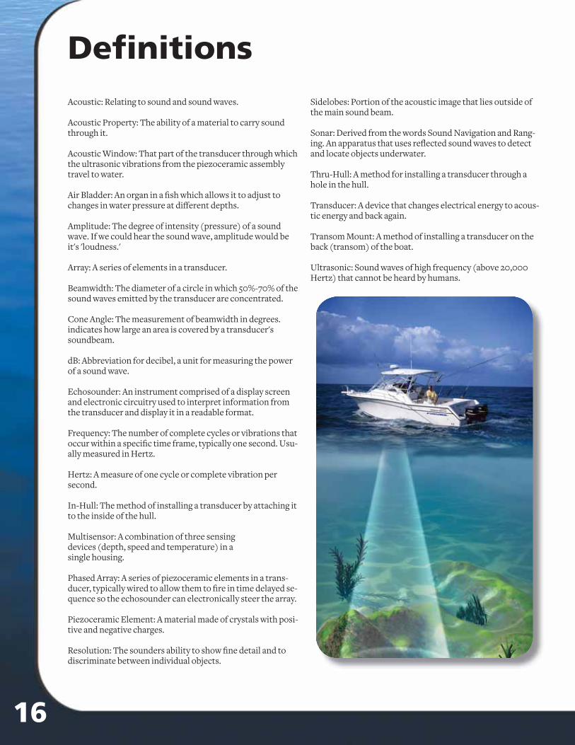
116
There are a wide variety of transducer options available for Furuno fi sh fi nders, but all of them operate on the same principle. At it’s most basic defi nition, a transducer is a device that takes en-ergy from one source, converts that energy into some other form and then delivers that energy to a target, such as a PA system converting sound from a microphone into electrical signals and then delivering that energy to the speakers. In the case of marine transducers, imagine that the same device can act as both the microphone and the speaker. Electricity from the fi sh fi nder is applied to the transducer, which sends out an acoustic signal - sound waves - into the water column. The transducer receives the refl ected echoes from objects that these sound waves en-counter and they are sent as an electrical signal to your fi sh fi nder. It is the fi sh fi nder's job to process this signal into a picture of the underwa-ter world on your screen.
The Essence of a TransducerThe physical device inside a transducer that creates the sound wave is a piezoceramic disc called the element. The element, when voltage is applied, vibrates - it distorts and reforms its shape in very rapid succession. This vibration oc-curs at a specifi c frequency and creates compres-sion waves, or acoustic energy - sound waves. These waves travel outward from the element in a vaguely cone-shaped pattern and encounter targets along the way.
As this acoustic energy encounters targets such as fi sh or bottom structure, some of the beam will be attenuated (absorbed by the target), some will be refl ected back at the transducer as an echo and some will be scattered. As the refl ected echoes strike the transducer they cause a minus-cule distortion in the shape of the crystal. This distortion of the crystal creates a small fl uctua-tion of voltage, which can be detected and
processed by the fi sh fi nder. The end result is an image on your display.
By measuring the time from when the sound wave is generated to when the return echo is received, we can learn the depth at which a target is encoun-tered. The strength of the refl ected echo can tell us about the size and density of the target.
Some transducers are referred to as single-ele-ment transducers. This means that they contain a single piezoceramic disc that vibrates alternately at 50kHz and 200kHz, utilizing both operating fre-quencies. Furuno off ers a wide range of single-ele-ment transducers that are very popular and carry a low price tag.
When greater performance is desired or required, multiple element transducers are available that can signifi cantly enhance the performance and sensitivity of your fi sh fi nder. A multiple-element transducer is one in which separate elements vibrate individually at their respective frequencies. Some high-end models utilize seven, nine or even fi fteen 50kHz elements along with a large-diameter 200kHz element. The dedicated 200kHz element off ers enhanced sensitivity in shallow water, while the greater surface area of the 50kHz array will receive echoes from deeper water with much more clarity and detail.
How it worksAcoustic: Relating to sound and sound waves.
Acoustic Property: The ability of a material to carry sound through it.
Acoustic Window: That part of the transducer through which the ultrasonic vibrations from the piezoceramic assembly travel to water.
Air Bladder: An organ in a fi sh which allows it to adjust to changes in water pressure at diff erent depths.
Amplitude: The degree of intensity (pressure) of a sound wave. If we could hear the sound wave, amplitude would be it's 'loudness.'
Array: A series of elements in a transducer.
Beamwidth: The diameter of a circle in which 50%-70% of the sound waves emitted by the transducer are concentrated.
Cone Angle: The measurement of beamwidth in degrees. indicates how large an area is covered by a transducer's soundbeam.
dB: Abbreviation for decibel, a unit for measuring the power of a sound wave.
Echosounder: An instrument comprised of a display screen and electronic circuitry used to interpret information from the transducer and display it in a readable format.
Frequency: The number of complete cycles or vibrations that occur within a specifi c time frame, typically one second. Usu-ally measured in Hertz.
Hertz: A measure of one cycle or complete vibration per second.
In-Hull: The method of installing a transducer by attaching it to the inside of the hull.
Multisensor: A combination of three sensing devices (depth, speed and temperature) in a single housing.
Phased Array: A series of piezoceramic elements in a trans-ducer, typically wired to allow them to fi re in time delayed se-quence so the echosounder can electronically steer the array.
Piezoceramic Element: A material made of crystals with posi-tive and negative charges.
Resolution: The sounders ability to show fi ne detail and to discriminate between individual objects.
Sidelobes: Portion of the acoustic image that lies outside of the main sound beam.
Sonar: Derived from the words Sound Navigation and Rang-ing. An apparatus that uses refl ected sound waves to detect and locate objects underwater.
Thru-Hull: A method for installing a transducer through a hole in the hull.
Transducer: A device that changes electrical energy to acous-tic energy and back again.
Transom Mount: A method of installing a transducer on the back (transom) of the boat.
Ultrasonic: Sound waves of high frequency (above 20,000 Hertz) that cannot be heard by humans.
Defi nitions
Many transducers are available with multiple elements for the 50kHz function and a single, large diameter 200kHz element, delivering enhanced performance.
* Shown with High Speed Fairing Block
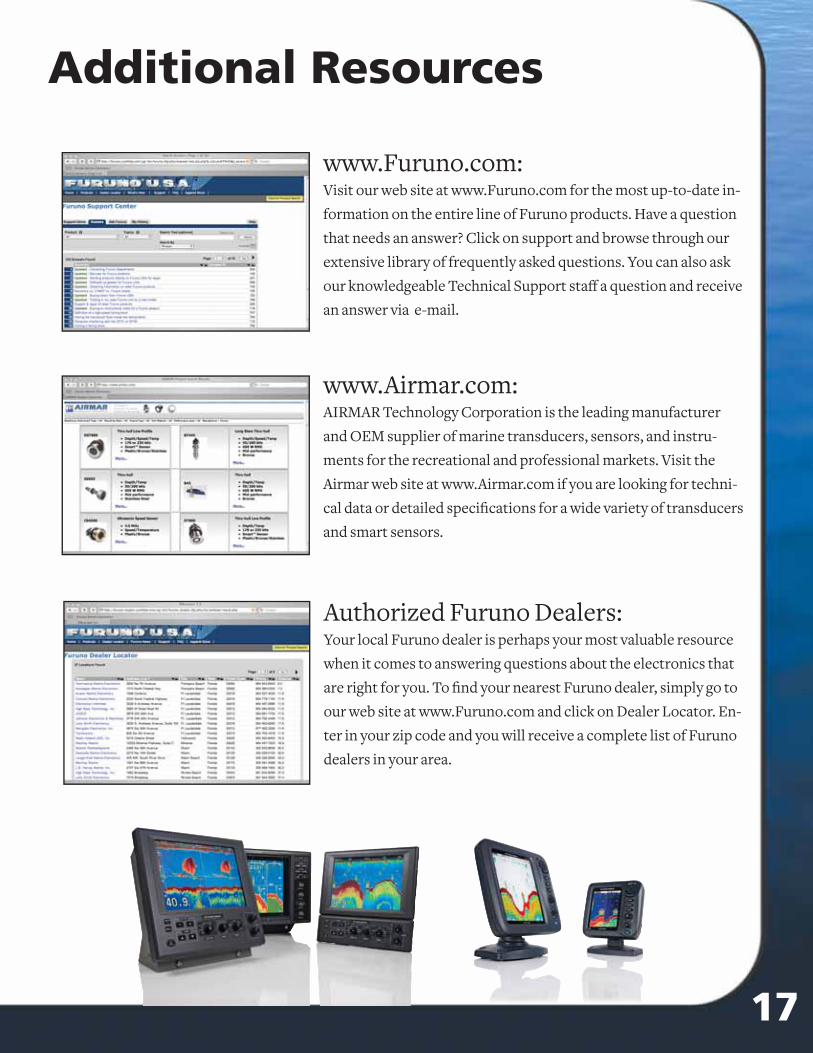
Furuno off ers a wide range of matched, high perfor-mance transducers for our depth sounders. There are transducers available for virtually every type and size of boat. There are also sensors you can install that will accurately read your boat speed and the surface water temperature. Because there are a number of variables in transducer types that can dramatically aff ect your fi sh fi nder's performance, understanding these variables is the key to selecting the right transducer. This book will help you learn about what makes a transducer ‘tick.’
17
Table of Contents1-3) Theory of Operation
4-5) Mounting Options & Installation tips
6-7) Getting the most out of your Fish Finder
8-10) Transducer Listings
11) Multisensors, Speed and Temperature sensors
12) Smart Sensors
13-15) FAQ's
16) Defi nitions
17) Additional Resources
Additional Resources
www.Furuno.com:Visit our web site at www.Furuno.com for the most up-to-date in-
formation on the entire line of Furuno products. Have a question
that needs an answer? Click on support and browse through our
extensive library of frequently asked questions. You can also ask
our knowledgeable Technical Support staff a question and receive
an answer via e-mail.
www.Airmar.com:AIRMAR Technology Corporation is the leading manufacturer
and OEM supplier of marine transducers, sensors, and instru-
ments for the recreational and professional markets. Visit the
Airmar web site at www.Airmar.com if you are looking for techni-
cal data or detailed specifi cations for a wide variety of transducers
and smart sensors.
Authorized Furuno Dealers:Your local Furuno dealer is perhaps your most valuable resource
when it comes to answering questions about the electronics that
are right for you. To fi nd your nearest Furuno dealer, simply go to
our web site at www.Furuno.com and click on Dealer Locator. En-
ter in your zip code and you will receive a complete list of Furuno
dealers in your area.
Pro anglers on the SKA and FLW circuits utilize the 50/200 kHz frequencies to fi nd their winning catch.

catch even more fi sh with our new dsp technology!
You’ve probably heard about digital fi sh fi nders, but aren’t quite sure what the difference is. The main difference is the fi ltering capabilities and auto adjustments. Our new DSP (Digital Signal Processing) technology adjusts the picture by fi ltering out items that you don’t need to see, while enhancing the fi sh targets! But even the best digital fi lter won’t help unless you start with a solid base, such as Furuno’s renowned fi sh fi nder technology. Anyone who knows fi shing will tell you that if you want the best fi sh fi nder, you need to go with Furuno. You’ll wonder how you ever managed without it!
NEW! FCV585 - 1kW or 600W
Dual-Frequency 50/200 kHz
8.4˝ Sunlight Viewable LCD
NEW! FCV620 - 600W
Dual-Frequency 50/200 kHz
5.6˝ Sunlight Viewable LCD
Go digital with Furuno and fi nd out!
After 35 years of awards, howcan our Fishfi nders get any better?
Go digital with Furuno and fi nd out!
After 35 years of awards, howcan our Fishfi nders get any better?
RADAR FISH FINDERS SONAR NAVIGATION COMMUNICATION AUTOPILOTS SOFTWARE
The most trusted name in marine electronics!www.Furuno.com
www.Furuno.com
Complete Angler's Guide to Marine Transducers