Embed Size (px)
Citation preview

University of Warwick institutional repository: http://go.warwick.ac.uk/wrap
This paper is made available online in accordance with publisher policies. Please scroll down to view the document itself. Please refer to the repository record for this item and our policy information available from the repository home page for further information.
To see the final version of this paper please visit the publisher’s website. Access to the published version may require a subscription.
Author(s): R. Bhagat, D. Dye, S.L. Raghunathan, R.J. Talling, D. Inman, B.K. Jackson, K.K. Rao and R.J. Dashwood Article Title: In situ synchrotron diffraction of the electrochemical reduction pathway of TiO2 Year of publication: 2010 Link to published article: http://dx.doi.org/ 10.1016/j.actamat.2010.05.041 Publisher statement: Citation: Bhagat, R. et al. (2010). In situ synchrotron diffraction of the electrochemical reduction pathway of TiO2. Acta Materialia, Vol. 58(15), pp. 5057-5062 .
In-Situ Synchrotron Diffraction of the Electrochemical Reduction Pathway of TiO2
R. Bhagata, D. Dyeb, S. L. Raghunathanb, R. J. Tallingb, D. Inmanb, B. K. Jacksonb, K. K. Raoc, and R. J. Dashwooda
a University of Warwick, Coventry, CV4 7AL, UKb Imperial College, London, SW7 2AZ, UK
c Metalysis, Rotherham, S63 5DB, UK
Despite over ten years of research into the low-cost electrowinning of titanium direct from the oxide, thereduction sequence of TiO2 pellets in molten CaCl2 has been the subject of debate, particularly as the reductionpathway has been inferred from ex-situ studies. Here, for the first time white beam synchrotron X-ray diffractionis used to characterize the phases that form, in-situ duringreduction and with∼100µm spatial resolution. It isfound that TiO2 becomes sub-stoichiometric very early in reduction facilitating the ionic conduction of oxygenions, that CaTiO3 persists to nearly the end of the process and that, finally, CaO forms just before completionof the process. The method is quite generally applicable to the in-situ study of industrial chemical processes.Implications for the industrial scale-up of this method forthe low-cost production of titanium are drawn.
I. INTRODUCTION
The FFC Cambridge process is an electrochemical methodby which metal oxides are reduced to metal using a moltenchloride flux [1]. The process is thought to have the potentialto lead to a step change in the cost of extraction of severalmetal alloy systems, including titanium. Currently the mostwidely used method for extracting titanium from rutile is theKroll process [2].
The FFC Cambridge reduction of TiO2 involves the pro-gressive reduction and deoxidation of a porous TiO2 pelletcathode in a molten halide salt. At the cathode the titaniumoxide is reduced to titanium and the oxide ions dissolve intothe calcium chloride. These oxide ions migrate to a carbonanode where they form carbon dioxide and carbon monoxide.The reduction pathway for this process has been studied usinga combination of pellet reductions [3], metal-cavity electrode[4] and thin-film experimentation [5].
Previous work by the present authors has focussed on thereduction of TiO2 using thin films [5] and metal-cavity elec-trodes [4]. Using cyclic voltammetry, these studies identifiedseveral electrochemical events taking place during reduction.These electrochemical events C4, C3, C2’, C2 and C1 wereidentified as reactions 1 to 6 respectively, usingex-situ X-ray diffraction (XRD) analysis of the thin-films removed aftereach reduction event. Despite being observed in XRD, the for-mation of CaTiO3 was not observed on the voltammograms.As such it was believed to form via a chemical reaction [6].
2TiO2 +2e− → Ti3O5 +O2− (1)
2Ti3O5 +2e− → 3Ti2O3 +O2− (2)
CaTiO3 +2e− → Ca2+ +TiO+2O2− (3)
Ti2O3 +2e− → 2TiO+O2− (4)
TiO+2e− → 2TiO+O2− (5)
TiO2 +Ca2+ +O2−→ CaTiO3 (6)
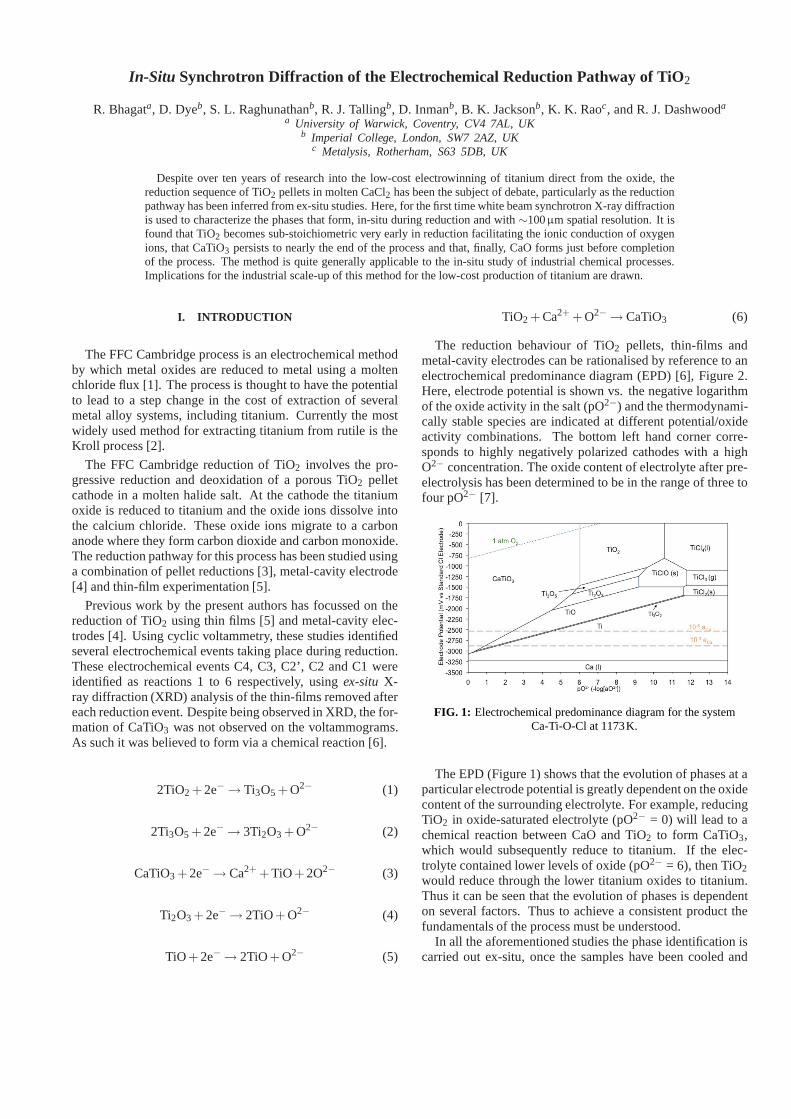
The reduction behaviour of TiO2 pellets, thin-films andmetal-cavity electrodes can be rationalised by reference to anelectrochemical predominance diagram (EPD) [6], Figure 2.Here, electrode potential is shown vs. the negative logarithmof the oxide activity in the salt (pO2−) and the thermodynami-cally stable species are indicated at different potential/oxideactivity combinations. The bottom left hand corner corre-sponds to highly negatively polarized cathodes with a highO2− concentration. The oxide content of electrolyte after pre-electrolysis has been determined to be in the range of three tofour pO2− [7].
FIG. 1: Electrochemical predominance diagram for the systemCa-Ti-O-Cl at 1173K.
The EPD (Figure 1) shows that the evolution of phases at aparticular electrode potential is greatly dependent on theoxidecontent of the surrounding electrolyte. For example, reducingTiO2 in oxide-saturated electrolyte (pO2− = 0) will lead to achemical reaction between CaO and TiO2 to form CaTiO3,which would subsequently reduce to titanium. If the elec-trolyte contained lower levels of oxide (pO2− = 6), then TiO2would reduce through the lower titanium oxides to titanium.Thus it can be seen that the evolution of phases is dependenton several factors. Thus to achieve a consistent product thefundamentals of the process must be understood.
In all the aforementioned studies the phase identification iscarried out ex-situ, once the samples have been cooled and

2
washed. This information is then correlated toin-situ voltam-metric or amperometric data. However, upon cooling anynumber of phase and crystallographic changes or compropor-tionation and disproportionation reactions may take place. Inaddition, washing may remove water-soluble species. Thishas resulted in erroneous and conflicting reduction pathwaysbeing proposed. By performingin-situ synchrotron X-raydiffraction (SXRD) on a FFC Cambridge cell whilst reducinga pellet of TiO2, we are able to present the first unequivocaldescription of the reduction pathway for TiO2.
II. RESULTS
The scans for the gauge volume closest to the bottom sur-face (1.2mm) of the sample are shown in Figure 2. The Ri-etveld refinements at key intervals in the reduction processareshown in Supplementary Figure 6. In some cases, due to thesmall gauge volume, insufficient grains were sampled to pro-duce a true powder pattern. In these case there was some dis-parity between the observed and calculated peak intensities.By analysing the scans from the bottom side of the sample(0, 0.3, 0.6, 0.9 and 1.2mm), molar fractions of the phasespresent were obtained (Figure 3).
FIG. 2: Evolution of the diffraction patterns obtained near thesurface of the pellet (1.2 mm from the centre).
The refined lattice parameters can be used to estimate theinterstitial oxygen content in theα-Ti phase. The thermal ex-pansion data for lattice parameter of Berry and Raynor [9],based on a temperature range of room temperature to 700◦C,was combined with the room temperature dependence of oxy-gen content on lattice parameter measured by Davidet al. [8].The data used are shown in Table I and the combined thermaland compositional effects are given in equations 7 and 8. Itshould be noted that the hexagonala-axis length is largely in-dependent of O content, so only thec-axis data was used in theanalysis. It is further assumed that the titanium that first forms
FIG. 3: Evolution of the phases present throughout the sample,obtained by Rietveld refinement.
was saturated with oxygen (14 wt.% O at 900◦C). The varia-tion in c-axis lattice parameter and inferred interstitial oxygencontent in theα-Ti phase are shown in Figure 4. By combin-ing this data with the phase fraction information the total oxy-gen content at different locations have been estimated, alongwith the total pellet oxygen content for comparison with the

3
TABLE I: α-Ti single crystal thermal expansion coefficients anddependence of lattice parameter on oxygen content - C(O).
a0 (nm)∗ 0.29511 [11]
c0 (nm)∗ 0.46826 [11]
αa ×10−6 (K−1) 11.03 [10]
αc ×10−6 (K−1) 13.37 [10]
da/dC(O)×10−4 (nmat. %−1) 0.78459 [11]
dc/dC(O)×10−4 (nmat. %−1) 4.7112 [11]∗ Measured at room temperature,∼ 0 ppm oxygen
time-current data, Figure 5.
FIG. 4: Variation in thec - lattice parameter ofα-Ti and inferredinterstitial oxygen content during reduction.
aαTi = a0(1+ ∆Tαα)+C(O)da
dC(O)(7)
cαTi = c0(1+ ∆Tαα)+C(O)dc
dC(O)(8)
The first scans of the gauge volumes (Figure 3) reveals thatrutile (TiO2), Ti4O7 and CaTiO3 are present at the beginningof reduction. The presence of Ti4O7 is consistent with thegeneral electronic theory of TiO2 [10–12], which states thatwhen TiO2 is subjected to a low oxygen atmosphere it beginsto equilibrate with the atmosphere. This is achieved via thecreation of defects in the crystal structure, which resultsinTiO2 being reduced. It should be noted that in addition toTi4O7, other Magneli phases (e.g Ti5O9) fit relatively well,indicating that a range of Magneli phases is present with themain phase being Ti4O7. This is the Magneli phase most oftendetected during the FFC reduction of TiO2 systems [3, 13].
The transformation to substoichiometric TiO2 phases andsubsequent release of oxygen ions into the electrolyte, resultsin the formation of CaTiO3. This is supported by the work ofJianget al. [14], whom suggest that the slight reduction ofTiO2 facilitates the transformation to the perovskite structure
FIG. 5: Evolution of oxygen content at different locations in thepellet (a) and total oxygen content of the pellet compared tothe
current variation during reduction (b).
of CaTiO3.It is interesting to note that the phase Ti3O5 is not detected
during reduction. Both the Ti-O phase diagram [15] and theEPD (Figure 1) predict that this phase should precede the for-mation of Ti2O3. In addition, significant quantities were ob-served by Schwandtet al. [3], by Dring et al. [5] and bythe authors duringex-situ analysis of thin films. The narrowhomogeneity range of Ti3O5 as shown in the EPD (Figure 1and Ti-O phase diagrams indicates that significant quantitieswould only form in-situ if the electrode potential were heldwithin the Ti3O5 phase field. It is hypothesised that the sig-nificant quantities of Ti3O5 observed by Schwandtet al. werea result of a disproportionation reaction of Magnli phases dur-ing cooling. It can be concluded that either the Ti3O5 fieldof stability is traversed rapidly or that kinetic considerationsprevent it from forming during reduction. Thus the observedformation of Ti3O5, by the aforementioned authors, would bea result of a disproportionation reaction during the cooling ofMagnei phases.
Ti2O3 seems to have a more significant impact on reduc-tion at the reduction temperature. It is detected at each gaugevolume. Figure 8 shows that Ti2O3 reduces to cubic TiO. Themonoclinic variant, alpha TiO, and Ti3O2, are not detected de-spite the fact that the Ti-O phase diagram [15] would suggestthat they would form at temperatures less than 940◦C. Thebeta TiO then gradually reduces to alpha Ti.
CaTiO3 and, in the inner regions of the pellet, CaTi2O4, arepresent for all but the last few hours of the reduction process.CaTiO3 is reported to have a large compositional range [17],however the derived lattice parameters for CaTiO3 remainquite consistent throughout reduction range. The authors havepreviously speculated that CaTiO3 can to some degree act asa solid electrolyte allowing the transmission of oxide ions[7].This could possibly account for the consistent stoichiometryof CaTiO3. At the surface layers it would appear that CaTiO3is reduced directly to Ti despite the fact that thermodynam-

4
ically this would only occur at very low pO2−. In the in-ner layers CaTi2O4 forms at the expense of CaTiO3 and TiO.CaTi2O4 has previously been detected by the authors [17] andSchwandt et al. [3] in pellet reductions of TiO2 based systems.It was theorised that the formation of this phase was either aresult of the electrochemical reduction of CaTiO3 or the resultof a comproportionation reaction between CaTiO3 and TiO.Figure 3 clearly shows that the formation of this phase clearlyresults in the equimolar consumption of TiO and CaTiO3 in-dicating that a comproportionation reaction is indeed respon-sible for its formation (reaction 9).
CaTiO3 +TiO → CaTi2O4 (9)
The conditions required to form CaTi2O4 have been stud-ied by Rogge et al. [18]. CaTiO3 and titanium metal powderwere combined with a CaCl2 flux at 1000◦C to form CaTi2O4.It was shown that equimolar or titanium rich mixtures wereneeded to form the compound. Rogge et al. [18] also observedthat when the titanium powder oxidised to TiO, CaTi2O4 wasnot formed, indicating that the comproportionation reactionprobably has a small positive∆G. Figure 3 shows that theformation of CaTi2O4 at the inner layers closely coincideswith the formation of titanium in the outer layers (0.6, -0.9and 1.2 mm). Formation of titanium in the outer layers willimprove the electrical conductivity of those layers, in effect,making them an extension of the titanium current collector.This would improve the electrochemical reducing conditionsin these layers allowing mixtures of TiO and CaTiO3 to com-proportionate.
Figure 5 shows that significant removal of oxygen takesplace at events 1, 2 and 3. When correlated to the molar frac-tions charts (Figure 3), event 1 can be identified as the for-mation of TiO. For the surface layers (1.2, -0.9 and 0.6mm),event 2 was identified as the reduction of TiO to titanium. Forthe inner layers (0.3 and 0 mm) event 2 is retarded due to theformation of CaTi2O4. Event 3 relates to the removal of CaO,which occurs at all locations with the exception of the cen-tre (0mm). Following the dissolution of CaO, the removal ofinterstitial oxygen from titanium commences.
CaO is detected throughout the pellet at the later stages ofreduction. This phase forms when the electrolyte in the poresbecomes saturated with oxide ions ( 22 mol.%). The onsetof CaO formation appears to correlate with the reduction ofCaTi2O4 in the inner layers. This results in a rapid evolutionof oxide ions that have to be transported through the pelletpores to the bulk electrolyte. During reduction the porosity ofthe pellet, which is originally highly porous (60% open poros-ity), is reduced through a combination of sintering of titaniumand formation of titanate phases. This significantly reducesthe permeability of the pellet allowing oxide ion saturation tooccur. Once event 2 is complete at the inner layers the flux ofoxide ions passing through the pellet diminishes. At this pointthe surface CaO rapidly dissolves which is closely followedby the subsequent inner layers.
The formation of TiC is another important event. Thisphase is often seen as a surface layer in reduced pellets. Two
mechanisms for TiC formation have been put forward by theauthors [7]. The first suggests that TiC is formed as a result ofa chemical reaction with carbon dust floating on the surfaceof the electrolyte that occurs as the sample is removed fromthe electrolyte. However the data supports the second mecha-nism, which involves the electrochemical deposition of carbonand subsequent reaction at the cathodic titanium surface ofthepellet. This occurs via the chemical formation of CO2−
3 via areaction between CO2 formed at the anode and O2− in theelectrolyte (reaction 10). This complex then is reduced at thecathode to form CaO and carbon. The carbon then chemicallyreacts with alpha titanium to form TiC (reaction 11).
CO2 +O2−→ CO2−
3 (10)
CO2−3 +Ti +4e− → 3O2− +TiC (11)
TiC formation is restricted to the surface of the pellet andonly forms at the later stages of the process. It is proposedthat TiC only forms once the cathode is sufficiently negativelypolarised for reaction 11 to take place. The potential at whichthis takes place will be dependant on the activity of both thecarbonate and oxide ions with the oxide ion activity having thedominant role. The oxide ion concentration in the region ofthe pellet will only reduce once reduction is nearly complete.Thus reaction 11 becomes more favourable once the processnears completion. Another interesting effect related to TiC isthat an increase in lattice parameter c (Figure 4 was observedat the latter stages of reduction at gauge volumes 0.6, 0.9 1.2mm. This increase coincides with the formation of TiC. AsTiC is a low oxygen phase when compared with alpha Ti theformation of TiC would causes the oxygen to partition into thealpha titanium, leading to an increase in oxygen content andlattice parameter c. In addition carbon has limited solubility inalpha titanium ( 0.15 at. %), which could result in an increasein lattice parameter. The low solubility of oxygen in TiC couldretard the formation of TiC until the oxygen content in thetitanium is sufficiently low.
III. DISCUSSION
The key findings of this paper can be summarised as fol-lows. It was found that upon entering the low oxygen at-mosphere, within the apparatus, TiO2 quickly forms substo-ichiometric phases, which significantly improves ionic con-ductivity over stoichiometric TiO2. In contradiction to thework of Schwandt et al. [3], it was found that CaTiO3 formschemically from the substoichiometric TiO2 phases. CaTi2O4was found to form from the comproportionation of TiO andCaTiO3 and was detrimental to the reduction process. Thephases Ti3O5, alpha TiO and Ti3O2 were not observed despitebeing predicted by the Ti-O phase diagram. The formationand eventual dissolution of CaO was related to the oxide fluxwithin the pellet. The deoxidation of titanium was found tooccur only once CaO had been removed locally within the

5
pellet. TiC was determined to form on the reduced pellet sur-face through anin-situ electrochemical process but only oc-curred when the oxygen content in the titanium reached ap-proximately 16 at. %.
The relative ease by which low electrical conductivity TiO2can be reduced via the FFC Cambridge process can be at-tributed to the low O2 partial pressure in the apparatus. Thisresults in a nearly instantaneous formation of electrically con-ductive Magneli phases. The time required to reduce TiO2pellets appears to be controlled by the formation of calciumcompounds (CaTiO3, CaTi2O4 and CaO). Their formationcauses reduces the permeability of the pores effectively caus-ing passivation. As a result understanding the mechanism bywhich these phases form and, more importantly, how to pre-vent their formation is key to improving the efficiency of theprocess. The chemical formation of CaTiO3, and hence thesubsequent formation of CaTi2O4 could be avoided if metaloxides with lower valence titanium oxides (i.e. Ti2O3 andTiO) are used as a starting product. Preventing the formationof the titanates will improve permeability and hence decreasethe likelihood of oxide saturation and hence CaO formation.Alternatively engineering of the preform geometry to max-imise initial pore size and permeability could reduce the dele-terious effect of titanate formation. The formation of titaniumcarbide appears to be unavoidable with the current cell design.Its formation can only be prevented if carbon free anodes areemployed or a membrane is used.
IV. METHODS
To form the TiO2 precursors, reagent grade TiO2 (99.5%Alfa Aesar) was ball milled with ethanol and zirconia spheresfor 24 h. The slurry was dried and the powder ground ina mortar and pestle with a small quantity of distilled water,which acted as a binding agent. 0.4g of powder was placedinto a 13mm diameter die prior to uniaxial compaction at100MPa. The precursors were then drilled to accept the com-mercial purity Ti cathodic current collector and placed in analumina-firing trough and sintered in argon (BOC pureshield-150mLmin−1 at 1373K for 3h at a rate of 3Kmin−1. The pel-lets were then ground to reduce the pellet diameter and weight
to approximately 7mm and 0.2g respectively.
The electrochemical cell was designed to minimise attenu-ation of the white X-ray beam and avoid additional sourcesof diffraction. Reductions were performed in a resistancefurnace-heated quartz glass reaction vessel (Figure 7), basedon that used previously [20]. Openings were incorporated intothe furnace to allow the synchrotron X-ray beams to pass. Aglassy carbon crucible was used to contain the salt and act asa consumable anode. Calcium chloride granules (Fluka) weredried and prepared [20] within the carbon crucibles whichwere then vacuum sealed prior to use.
The apparatus was heated at a rate of 1Kmin−1 under ar-gon (BOC pureshield - 50mLmin−1) from room temperatureto the electrolysis temperature (1173K). The electrolyte wasthen thermally equilibrated for three hours. Prior to exper-iments the salt was pre-electrolysed for 1− 3h to removeelectro-active impurities by polarising a grade 2 CP-Ti rod(3mm) versus the graphite crucible.
The sintered metal oxide precursor was attached to the ti-tanium current collector and suspended above the salt priorto pre-electrolysis. Following the pre-electrolysis the precur-sor was lowered into the molten salt and polarised at a rate of0.5mVs−1 from open circuit to−3100mV versus the carbonanode.
The ID15A beamline at the ESRF was used to produce anunmonochromated (white) X-ray beam in an energy disper-sive mode. A 50µm by100µm incident beam and 5◦ scat-tering angle were defined by slits yielding a gauge lengthof 1000µm (Supplementary Figure 7). The assembly wasmounted on a translation stage allowing nine locations at dif-ferent heights in the pellet to be studied. Diffraction spectrawere collected for 6s each for a total reduction time of 67ks(18.5h).
The SXRD plots produced for each time and position wereanalyzed by Rietveld refinement using GSAS [20], allowingthe phases present to be identified and atomic fractions to beobtained. The source spectrum was normalized using both anAl powder and the powder TiO2 pattern obtained from the pel-let prior to insertion into the cell. Beam hardening within thecell was accounted for by comparison with the initial patternsobtained from the pellet.
[1] Chen G., Fray D.J. and Farthing T.W., Direct ElectrochemicalReduction of Titanium Dioxide in Molten Calcium Chloride.Nature, 2000. 407: p. 361-364.
[2] Kroll W., The Production of Ductile Titanium. Seventy-EighthGeneral Meeting, 1940: p. 35-47.
[3] Schwandt C. and Fray D.J., Determination of the kinetic path-way in the electrochemical reduction of titanium dioxide inmolten calcium chloride. Electrochimica Acta, 2005. 51(1): p.66-76.
[4] Rao K., Brett D., Inman D. and Dashwood R.J., Investigation ofthe Reduction Electrochemistry of Titanium Oxides in MoltenCalcium Chloride Using Cavity Electrode. in Ti-2007. 2007.Japan: The Japanese Institute of Metals.
[5] Dring K., Dashwood R.J. and Inman D., Voltammetry of Tita-
nium Dioxide in Molten Calcium Chloride at 900◦C. Journal ofThe Electrochemical Society, 2005. 152(3): p. E104-E113.
[6] Dring K., Dashwood R.J. and Inman D., Predominance Dia-grams for Electrochemical Reduction of Titanium Oxides inMolten CaCl2. Journal of The Electrochemical Society, 2005.152(10): D184-D190.
[7] Bhagat R., The Electrochemical Formation of Titanium AlloysVia the FFC Cambridge Process, in Departemnt of Materials.2008, Imperial College London: London. p. 1-133.
[8] David D., Garcia E.A., Lucas X. and Beranger G., Etude de laDiffusion de l’Oxygene Dans le Titane a Oxyde Entre 700◦C et950◦C Journal of the Less-Common Metals, 1979. 65: p. 51-69.
[9] Berry R.L.P. and Raynor G.V., Research, 1953. 6(21S).[10] Bak T., Nowotny J., Rekas M. and Sorrell C.C., Defect Chem-

6
istry and Semiconducting Properties of Titanium Dioxide: II.Defect Diagrams. Journal of Physics and Chemistry of Solids,2003. 64(7): p. 1057-1067.
[11] Nowotny J., Radecka M. and Rekas M., Semiconducting Prop-erties of Undoped TiO2 Journal of Physics and Chemistry ofSolids, 1997. 58(6): p. 927-937.
[12] Nowotny J., Radecka M. and Rekas M., Sugihara S., Vance E.R.and Weppner W., Electronic and Ionic Conductivity of TiO2Single Crystal Within the n-p Transition Range. Ceramics In-ternational, 1998. 24(8): p. 571-577.
[13] Alexander D.T.L., Schwandt C. and Fray D.J., MicrostructuralKinetics of Phase Transformations During ElectrochemicalRe-duction of Titanium Dioxide in Molten Calcium Chloride. ActaMaterialia, 2006. 54(11): p. 2933-2944.
[14] Jiang K., Hu X., Ma M., Wang D., Qiu G., Jin X. andChen G.Z., ”Perovskitization” - Assisted ElectrochemicalRe-duction of Solid TiO2 in Molten CaCl2. Angewandte ChemieInternational Edition, 2006. 45(3): p. 428-432.
[15] Murray J.L. and Wriedt H.A., O-Ti Phase Diagram. ASM In-ternational. 1987, Ohio. 148-165.
[16] Bak T, Nowotny J and Sorrel CC, Chemical Diffusion in Cal-cium Titanate. Journal of Physics and Chemistry of Solids,2004. 65(7): p. 1229-1241.
[17] Bhagat R., Jackson M., Inman D. and Dashwood R.J., Produc-tion of Ti–W Alloys from Mixed Oxide Precursors via the FFCCambridge Process. Journal of The Electrochemical Society,2009. 156(1): p. E1-E7.
[18] Rogge M.P., Caldwell J.H., Ingram D.R., Green C.E., Gesel-bracht M.J. and Siegrist T., A New Synthetic Route to Pseudo-Brookite-Type CaTi2O4. Journal of Solid State Chemistry,1998. 141: p. 338-342.
[19] Bhagat R., The Electrochemical Formation of Titanium AlloysVia the FFC Cambridge Process, in Departemnt of Materials.
2005, Imperial College.[20] Larson A.C. and Von Dreele R.B., Los Alamos National Labo-
ratory Report, 2000. LAUR(86).
The authors gratefully acknowledge the Defence Advanced Re-search Project Agency (DARPA), the Office of Naval Research andthe Engineering and Physical Sciences Research Council (EPSRC)for their support. The authors also thank T. Buslaps, J. Daniels andA. Steuer at the ESRF for beam line assistance. The authors wouldalso give thanks to M. Jackson for his assistance during experimen-tation.
V. AUTHORS CONTRIBUTION
R. J. Dashwood and D. Dye conceived and designed the study.B. K. Jackson, R. J. Dashwood and D. Dye designed the apparatus,which B. K. Jackson built and commissioned the apparatus. R.Bha-gat, R. J. Dashwood, D. Dye, S. L. Raghunathan, R.J. Talling,K.K. Rao and conducted the experiments. R. Bhagat and S.L. Raghu-nathan analysed the data with support from R.J. Talling, R. J. Dash-wood and D. Dye. The paper was written by R. Bhagat with con-tributions and editing from R. J. Dashwood, D. Dye, D. Inman,R.J.Talling and S.L. Raghunathan.
VI. SUPPLEMENTARY FIGURES

7
FIG. 6: Rietveld refinements and diffraction spectra obtained nearthe surface of the pellet (1.2mm from the centre). Key peaks
labelled.

8
FIG. 7: Schematic of electrochemical apparatus used for the in situX-ray studies, showing several gauge volumes present during
experimentation.