Embed Size (px)
Citation preview
Peripherals and their Control
An overview of industrially available “peripheral devices”
Some ideas for Laboratories and Quiz / Exam questions
To be tackled today
• Analog Output Devices – These could be handled via A/D as we did with an audio signal in Lab.
1. Depends on amplitude and frequency of the signals generated by the devices.
• SPI devices – Tackled in Lab. 4– LCD screen using a SPI – serial to parallel converter– LCD colour screen (Lab. 0, 2 and 4)– MC33993 Multiple ‐‐ Switch Detection Interface– ADIS16003 accelerometer and temperature sensor
• Digital Output – modulated pulse width– Handle with PF interface as with switches– TSL230R – Light sensor – ADI ‐ TMP03 thermometer – Lab. 3 – ADXL213 Dual Axis Accelerometer – Done in lecture
• Those interested – might be able to work out special Lab. 3 substitute – Four times the fun – eight times the work?
MMA6260QDual Axis Accelerometer – Analog Output
Left Channel ?
Right Channel?
Could we modify the “Talk-through program from Lab. 1 to work withthis accelerometer?• Concern 1 – voltage levels – too high voltages would destroy Blackfin A/D• Concern 2 – is the 48 kHz bandwidth of the audio A/D enough
Probable solution – use a non-audio, more general A/D connected via SPI interface
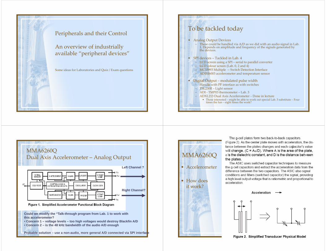
MMA6260Q
• Accelerometer
• How doesit work?
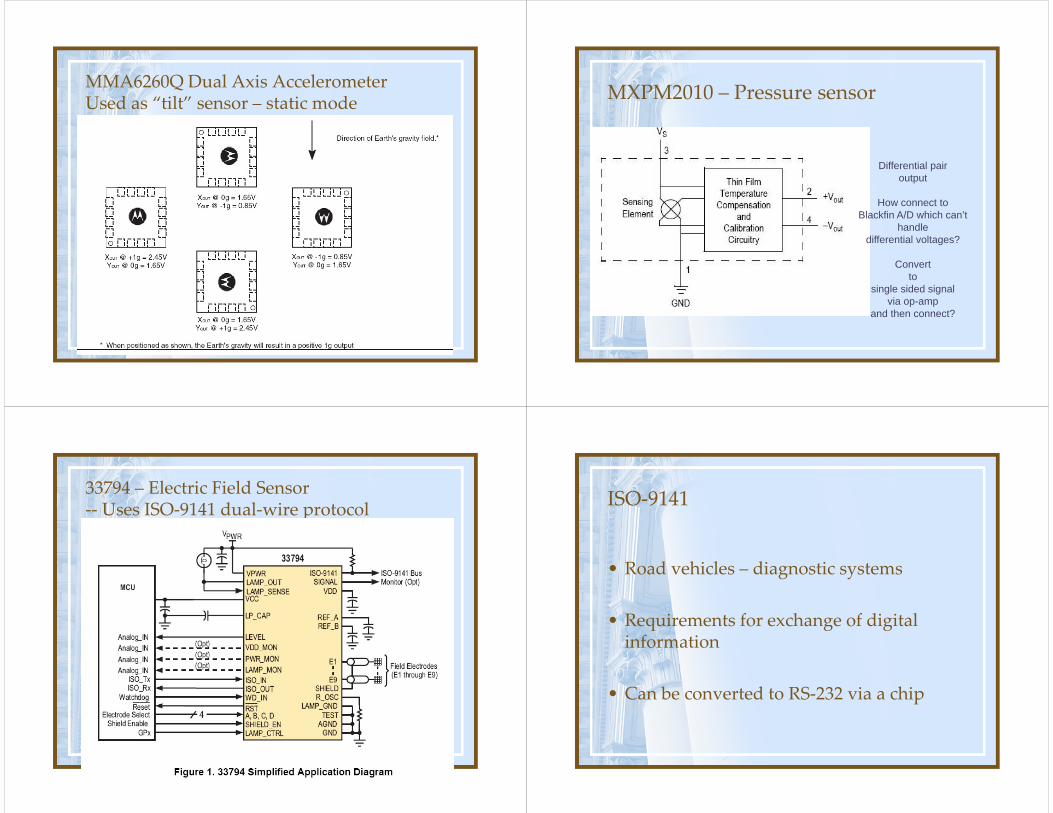
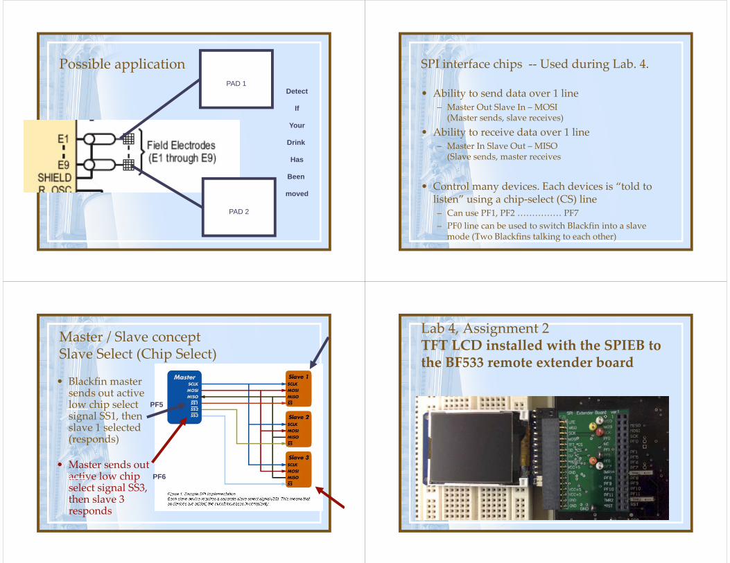
MMA6260Q Dual Axis AccelerometerUsed as “tilt” sensor – static mode MXPM2010 – Pressure sensor
Differential pairoutput
How connect to Blackfin A/D which can’t
handle differential voltages?
Convert to
single sided signalvia op-amp
and then connect?
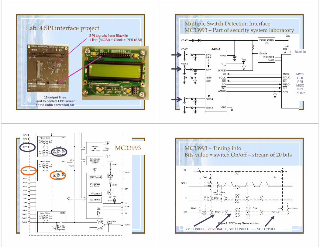
33794 – Electric Field Sensor‐‐ Uses ISO‐9141 dual‐wire protocol ISO‐9141
• Road vehicles – diagnostic systems
• Requirements for exchange of digital information
• Can be converted to RS‐232 via a chip
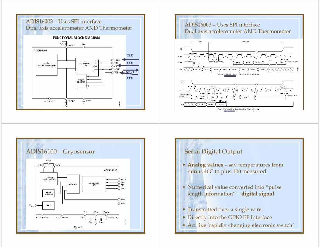
Possible applicationPAD 1
PAD 2
Detect
If
Your
Drink
Has
Been
moved
SPI interface chips ‐‐ Used during Lab. 4.
• Ability to send data over 1 line– Master Out Slave In – MOSI
(Master sends, slave receives)
• Ability to receive data over 1 line– Master In Slave Out – MISO
(Slave sends, master receives
• Control many devices. Each devices is “told to listen” using a chip‐select (CS) line– Can use PF1, PF2 …………… PF7– PF0 line can be used to switch Blackfin into a slave
mode (Two Blackfins talking to each other)
Master / Slave conceptSlave Select (Chip Select)
• Blackfin master sends out active low chip select signal SS1, then slave 1 selected (responds)
• Master sends out active low chip select signal SS3, then slave 3 responds
PF5
PF6
Lab 4, Assignment 2TFT LCD installed with the SPIEB to the BF533 remote extender board
Lab. 4 SPI interface projectSPI signals from Blackfin1 line (MOSI) + Clock + PF5 (SSI)
16 output linesused to control LCD screenor the radio controlled car
Multiple Switch Detection InterfaceMC33993 – Part of security system laboratory
Blackfin
MOSICLKPF5
MISOPF9
PF10?
MC33993 MC33993 – Timing info Bits value = switch On/off – stream of 20 bits
SG13 ON/OFF, SG12 ON/OFF, SG11 ON/OFF ----- SO0 ON/OFF ………….
ADIS16003 – Uses SPI interfaceDual axis accelerometer AND Thermometer
CLK
PF5
MISO
PF6
ADIS16003 – Uses SPI interfaceDual axis accelerometer AND Thermometer
ADIS16100 – Gryosensor Serial Digital Output
• Analog values – say temperatures from minus 40C to plus 100 measured
• Numerical value converted into “pulse length information” – digital signal
• Transmitted over a single wire• Directly into the GPIO PF Interface• Act like ‘rapidly changing electronic switch’
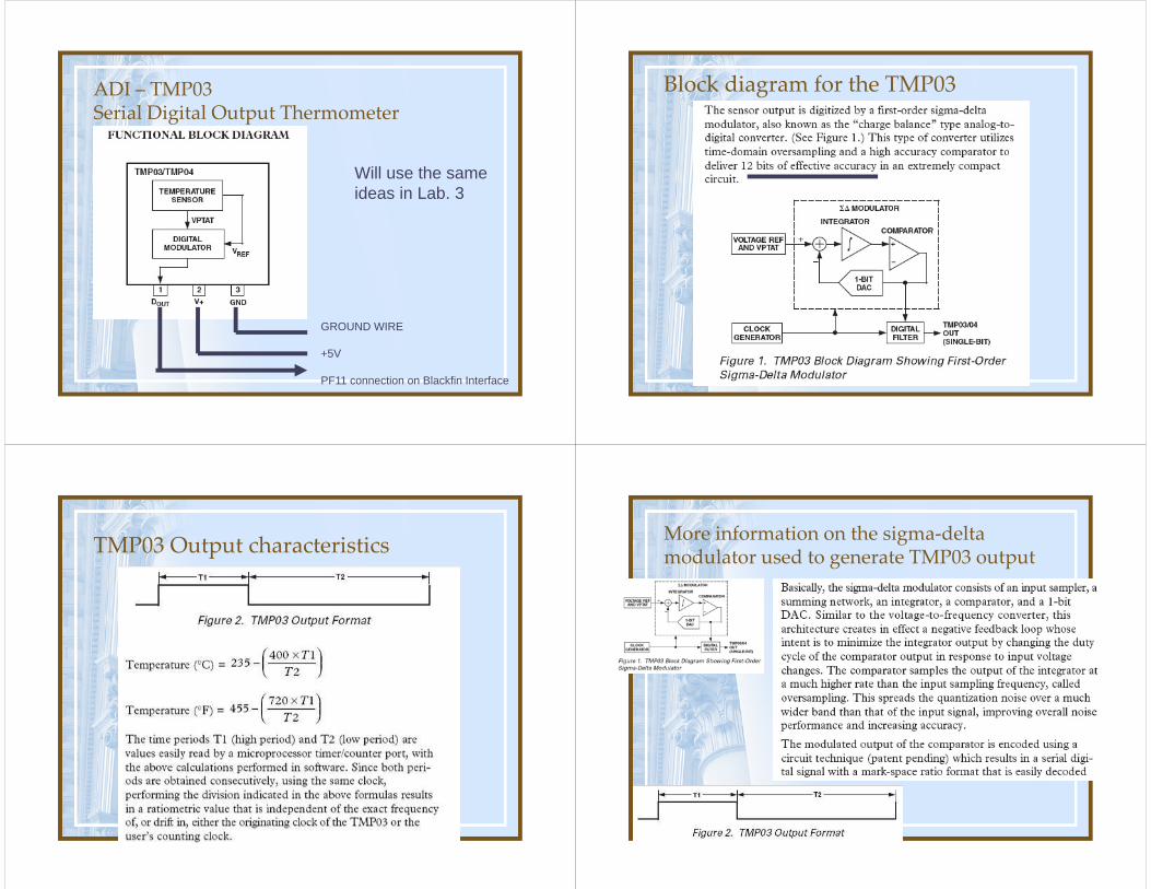
ADI – TMP03 Serial Digital Output Thermometer
GROUND WIRE
+5V
PF11 connection on Blackfin Interface
Will use the same ideas in Lab. 3
Block diagram for the TMP03
TMP03 Output characteristics More information on the sigma‐delta modulator used to generate TMP03 output

ADXL213 Dual Axis Accelerometer
PF9
PF8
ADXL213 Dual Axis Accelerometer
PF9
PF8
ADXL213 Dual Axis Accelerometer ADXL213 Dual Axis AccelerometerOutput when used as “tilt sensor”
X 50%Y 50%
X 50%Y 80%
X 50%Y 20%
Reference Information
• Pictures are taken from various data sheets available from the Analog Devices and Freescale (Motorola) web sites
• Proposed use of devices are for concept purposes only and no guarantee is made regarding suitable of circuits suggested
• Application notes are also available on the website