Embed Size (px)
Citation preview
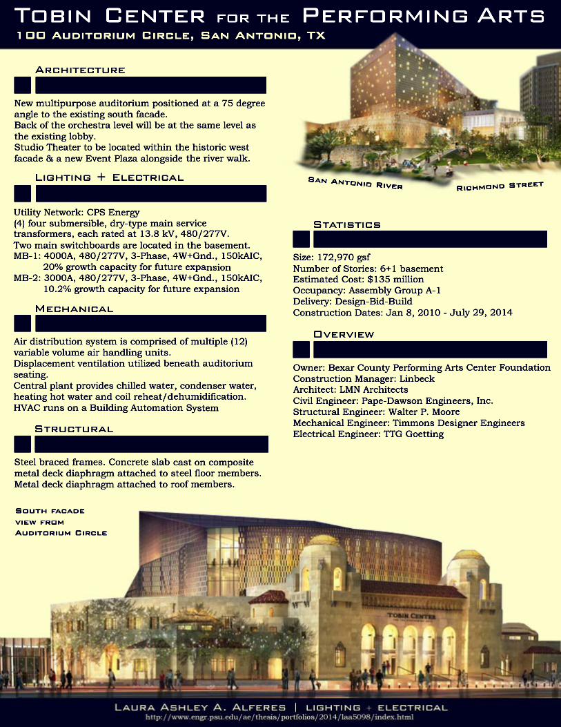
Tobin Center
for the Performing Arts
San Antonio, TX
Final Thesis Report
Laura Ashley A. Alferes
Lighting │ Electrical
Faculty Advisor │ Dr. Kevin Houser
04.09.2014
Tobin Center for the Performing Arts │ Final Thesis Report │ Laura Ashley Alferes
2 | P a g e
Executive Summary
This thesis focused on the Tobin Center for the Performing Arts in San Antonio, TX. Historically
known as the Municipal Auditorium, the Tobin Center will be transformed into a striking
architectural landmark, both locally and nationally. The primary elements consist of a 1,750
seat H-E-B Performance Hall; a 200 seat flat floor Alvarez Family Studio; the Leroy Denman
Founders Lounge; McCombs Grand Lobby; and a River Walk Plaza.
Within this thesis, several systems, methods, and their results were thoroughly studied during
a yearlong capstone project on the Tobin Center for the Performing Arts. The fall 2013 semester
included an investigation of existing systems and to further study spaces for analysis and
potential redesign. The spring 2014 semester concentrated on developing design concepts and
integrating alternative engineering systems.
This thesis contains lighting and electrical depths, as well as construction management and
mechanical breadths. The lighting depth explores design alternatives for a circulation space, a
special purpose space, a large work space, and an outdoor space. The electrical depth analyzes
a branch circuit redesign based on new lighting loads, a short circuit analysis, and finally the
implementation of a Building-Integrated Photovoltaic (BIPV) system.
The construction management is interrelated with the BIPV system, in which a cost and
schedule analysis was performed. The mechanical breadth studies the potential use of biogas
as a renewable energy source, especially for cogeneration purposes.
All sections of this thesis project are based on a thorough examination of the building, as well
as a coherent design solution to address the potential for system alternatives.
Tobin Center for the Performing Arts │ Final Thesis Report │ Laura Ashley Alferes
3 | P a g e
Table of Contents
Executive Summary .............................................................................................................................. 2
Section One ǀ project background ......................................................................................................... 4
Section Two ǀ building statistics ............................................................................................................ 5
Site Information ............................................................................................................................... 5
General Building Data .................................................................................................................. 6
Architectural Information ........................................................................................................ 6
Sustainability Features ............................................................................................................... 8
Construction Method .................................................................................................................. 8
Lighting System ................................................................................................................................ 8
Electrical System ........................................................................................................................... 8
Mechanical System ......................................................................................................................... 9
Structural System ......................................................................................................................... 9
Section Three ǀ lighting depth ............................................................................................................ 10
Main Lobby ǀ circulation space ............................................................................................... 10
Patron’s Lounge ǀ special purpose space ......................................................................... 16
Main Auditorium ǀ large work space .................................................................................... 21
Event Plaza ǀ outdoor space ................................................................................................... 26
Section Four ǀ electrical depth ........................................................................................................... 32
Section Five ǀ construction management breadth .............................................................................. 55
Section Six ǀ mechanical breadth ......................................................................................................... 58
Summary & Conclusion .................................................................................................................. 63
References ........................................................................................................................................... 64
Acknowledgements ......................................................................................................................... 65
Appendix .................................................................................................................................................. 66
Appendix I: Lighting Catalogues .............................................................................................................. 66
Appendix II: Electrical Calculations, SAM graphs and data ..................................................................... 66
Appendix III: Original Construction Schedule ......................................................................................... 66
Tobin Center for the Performing Arts │ Final Thesis Report │ Laura Ashley Alferes
4 | P a g e
Section One ǀ project background
The existing south façade, known as the Municipal Auditorium, is located in Bexar County of
San Antonio, TX. It’s considered one of the finest examples of the Spanish Revival style found
in a public building in Texas. At the time of its construction, this style was very popular. The
new addition, which is the bulk of this thesis report, will exemplify today’s popular style of
modern aesthetics and extensive interior and exterior design integration.
San Antonio looks forward to the completion of the TCPA because the old and new style of
design will become one. The building shall continue to be a valuable cultural landmark of the
city, interlocking the life of the building with the life of the city.
Tobin Center for the Performing Arts │ Final Thesis Report │ Laura Ashley Alferes
5 | P a g e
Section Two ǀ building statistics
The following subsections describe the site location, building type and project team, as well as the various systems used throughout the Tobin Center.
Site Information
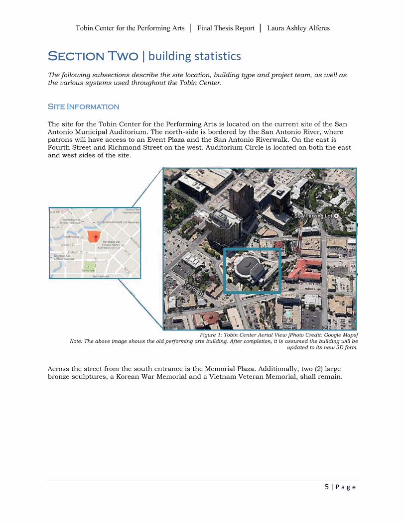
The site for the Tobin Center for the Performing Arts is located on the current site of the San Antonio Municipal Auditorium. The north-side is bordered by the San Antonio River, where patrons will have access to an Event Plaza and the San Antonio Riverwalk. On the east is Fourth Street and Richmond Street on the west. Auditorium Circle is located on both the east and west sides of the site.
Figure 1: Tobin Center Aerial View [Photo Credit: Google Maps]
Note: The above image shows the old performing arts building. After completion, it is assumed the building will be updated to its new 3D form.
Across the street from the south entrance is the Memorial Plaza. Additionally, two (2) large bronze sculptures, a Korean War Memorial and a Vietnam Veteran Memorial, shall remain.
Tobin Center for the Performing Arts │ Final Thesis Report │ Laura Ashley Alferes
6 | P a g e
General Building Data
Building Name: Tobin Center for the Performing Arts
Location and Site: 100 Auditorium Circle, San Antonio, TX 78205
Building Occupant Name: Tobin Center for the Performing Arts
Occupancy Types: Assembly Group A-1 (Primary Occupancy)
Size: 172,970 GSF
Number of Stories Above Grade: 6 + 1 Basement
Primary Project Team:
Owner: Bexar County Performing Arts Center Foundation
Owner’s Rep: The Projects Group, Zacry Construction Corp.,
Marmon Mok
Construction Manager: Linbeck
Architect of Record/FOH (Prime): LMN Architects
Civil Engineer: Pape-Dawson Engineers, Inc.
Structural Engineer: Walter P. Moore (Prime/FOH)
Mechanical & Plumbing Engineer: Timmons Designer Engineers (Prime)
Electrical Engineer: TTG Goetting
Architectural Lighting: Horton Lees Brogden, Inc.
Dates of Construction: January 8, 2010 – July 29, 2014
Projected Cost of Project: $135 million
Project Delivery Method: Design-Bid-Build
Architectural Information
The Tobin Center for the Performing Arts is an inspiring expression for the performing arts in
San Antonio. Its design integrates functionality, theatricality, and community in both its
historic elements and new addition. The design is driven by four distinctive objectives
To maintain the primary historic and iconic facades, as well as enhance the south entry
To create a dynamic interplay of form, geometry and material between historic elements
and the new addition
To orient the Studio Theater and lobby toward the San Antonio River
To integrate a new Event Plaza along the San Antonio River Walk, encouraging more
city events and outdoor performance space
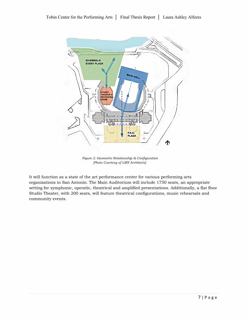
The key to these objectives is the geometric relationship of the new multipurpose auditorium to
the historic south façade and arcade wings, known as the Municipal Auditorium. Therefore, the
new multipurpose auditorium will be positioned at a 75° angle to the existing south façade,
and the back of the orchestra level will be at the same level as the existing lobby. This
configuration allows for the Studio Theater to be located within the historic west façade and a
new Event Plaza alongside the river walk.
Tobin Center for the Performing Arts │ Final Thesis Report │ Laura Ashley Alferes
7 | P a g e
Figure 2: Geometric Relationship & Configuration
[Photo Courtesy of LMN Architects]
It will function as a state of the art performance center for various performing arts
organizations in San Antonio. The Main Auditorium will include 1750 seats, an appropriate
setting for symphonic, operatic, theatrical and amplified presentations. Additionally, a flat floor
Studio Theater, with 200 seats, will feature theatrical configurations, music rehearsals and
community events.
Tobin Center for the Performing Arts │ Final Thesis Report │ Laura Ashley Alferes
8 | P a g e
Sustainability Features
The Bexar County Performing Arts Center [BCPAC] strives for sustainability in this venue.
Through preservation, restoration, and rehabilitation, especially with an existing structure
such as the Municipal Auditorium, a sustainable act is in practice. To evaluate sustainable
features, two versions of the LEED for new construction [LEED-NC] Rating System have been
adopted: version 2.2 & 2009. Using either version makes it possible to achieve LEED
certification
LEED-NC 2.2 LEED-NC 2009 Registered as LEED NCv2.2
As a guide to sustainability, the target is to understand the location of the city. This promotes
public transportation, use of exterior plazas for public space, outdoor air delivery monitoring,
and water conserving plumbing fixtures and water reuse.
Construction Method
Linbeck Group, LLC is the construction management firm for the Tobin Center. The delivery
method is design-bid-build, with a projected budget of $135 million. Additionally, the project
has a second budget that address upgrades to the site, specifically for improved access to the
San Antonio Riverwalk, an Event Plaza, and a memorial to veteran Medal of Honor winners
from San Antonio.
Lighting System
Fluorescent, incandescent, HID, and LED fixtures are used throughout. The stage and house
lighting control system will include a number of twenty ampere and fifty ampere high-density,
solid-state dimmers, as well as single-pole and two-pole relays that feed receptacles in outlet
boxes above the stage and in the auditorium in a dimmer-per-circuit configuration. This
system will be controlled by an electronic memory to establish, store, and recall preset
intensity levels and fade times that can be accessed from both the main control console and
remote pushbutton or touchscreen preset stations.
Electrical System
The utility service, CPS Energy, provides power for each of the four submersible, dry-type main
service transformers, each rated at 13.8 kV on the primary and 480/277V on the secondary.
They are sized, controlled and engineered by the local utility company. The main service from
these transformers is provided through two indoor, surface-mounted, single-ended main
switchboards, MSB-1 and MSB-2, located in the main electrical room of the basement. Both
switchboards are 480/277V, 3-phase, 4 wires + ground, 150 kAIC, with NEMA 1 enclosure.
MSB-1 and MSB-2 steps down the voltage of either 208Y/120V or 218Y/126V to switchboards
and distribution panels. Emergency power is provided by a diesel generator rated at 250
kW/312.5 kVA. No optional back-up power exists in the system.
Tobin Center for the Performing Arts │ Final Thesis Report │ Laura Ashley Alferes
9 | P a g e
Mechanical System
The mechanical system, which is run by a BAS, is designed to optimize performance, and
minimize maintenance and energy use. A newer technique of displacement ventilation is
utilized beneath auditorium seating. It offers thermal comfort for patrons, the quietest possible
air distribution, and energy efficiency advantages. Conditioned air is distributed near the
patrons, and as it warms, it rises to the top of the auditorium volume. Optimum indoor air
quality is provided by supplying air at low levels and driving contaminants out of the occupied
air zone. In addition to comfort, the noise reduction associated with displacement helps to meet
acoustical requirements, especially since auditoriums and theaters, in general, are sound-
sensitive.
Structural System
The ability of the structural frame to resist lateral loads and provide stability under gravity
loads derives from the complete installation of a lateral-force resisting system and diaphragm.
Included in the structure are steel braced frames. A concrete slab cast on composite metal
deck diaphragm is completely attached to all steel floor members. A metal deck diaphragm is
completely attached to all roof members. The entire diaphragm creates a continuous element
linking the lateral-force resisting system to all other columns.
Tobin Center for the Performing Arts │ Final Thesis Report │ Laura Ashley Alferes
10 | P a g e
Section Three ǀ lighting depth
The purpose of the performing arts center is to bring people together to witness several forms of
creative activity, in which artists use their body and/or voice to convey artistic expression. With
this as a driving force, lighting for the Tobin Center will aim to create engaging environments that
are welcoming to patrons and visitors. It will enhance the idea of having the opportunity and
responsibility of supporting the goals of the Tobin Center in inspirational and pragmatic ways. To
inspire and welcome, the lighting must resonate with the community and celebrate connections
between the Tobin Center, the greater fabric of San Antonio, and the Riverwalk.
Equally, to realize its greatest potential, the functional and technical aspects of security, visibility
and maintenance will be integrated into the design of the architectural and landscape lighting
components.
Main Lobby ǀ circulation space
DESCRIPTION
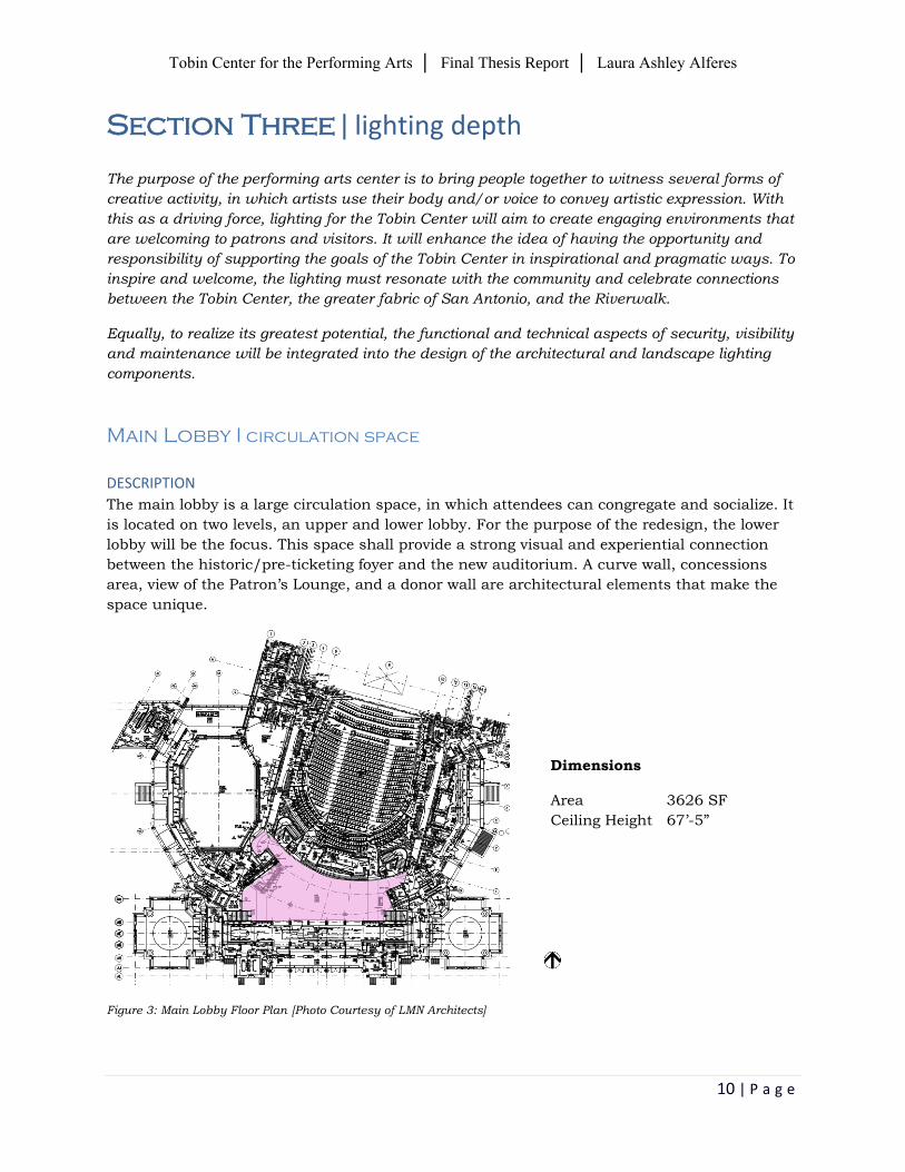
The main lobby is a large circulation space, in which attendees can congregate and socialize. It
is located on two levels, an upper and lower lobby. For the purpose of the redesign, the lower
lobby will be the focus. This space shall provide a strong visual and experiential connection
between the historic/pre-ticketing foyer and the new auditorium. A curve wall, concessions
area, view of the Patron’s Lounge, and a donor wall are architectural elements that make the
space unique.
Figure 3: Main Lobby Floor Plan [Photo Courtesy of LMN Architects]
Dimensions
Area 3626 SF
Ceiling Height 67’-5”

Tobin Center for the Performing Arts │ Final Thesis Report │ Laura Ashley Alferes
11 | P a g e
SURFACE MATERIAL Surface Type Description Reflectance
(Upper Lobby/Lower Lobby)
Floor TER-1/2/3 Thinset Epoxy Terrazzo 50%/20%
North Wall GFRG-1
Glass Fiber Reinforced Gypsum Panels, paint with ArmourColor, Perlata sprayed textured, with clearseal gloss Color: PLS
80%/50%
PNT-12 Paint Color No. DEA109 Bonfire Flame Manufacturer: Dunn Edwards
80%/50%
E & W Wall PNT-5 Paint Color. No. OC-138 White Drifts Manufacturer: Benjamin Moore
80%/50%
PNT-12 Paint Color No. DEA109 Bonfire Flame Manufacturer: Dunn Edwards
80%/50%
South West PNT-5 Paint Color. No. OC-138 White Drifts Manufacturer: Benjamin Moore
80%/50%
Ceiling PNT-6 Paint Color No. OC-64 Pure White Manufacturer: Benjamin Moore
80%/80%
SPCLG-1 Support Ceiling 80%/80%
DESIGN CRITERIA
Qualitative Criteria:
The main lobby serves as the primary transition space between the historic entry/pre-ticketing
foyer and the new main auditorium. The lighting in this space should be engaging and inviting,
allowing patrons to gain a strong sense of layers of architecture. Therefore, various layers of
lighting shall be zoned separately, allowing for a flexible lighting system to respond to the
various uses of the main lobby.
Additional criteria that was considered included: (1) general lighting to meet illuminance
recommendations for safety regulations, (2) having a dramatic difference in lighting approach
from the pre-ticketing foyer, which has a lower ceiling, into the main lobby, and (3) special
lighting treatment should be incorporated to distinguish destination points, especially the main
auditorium’s entry.
IES suggested very important criteria:
Appearance of space and luminaires
Point(s) of interest
IES suggested important criteria:
Modeling of faces and objects
Surface characteristics
Quantitative Criteria: Illuminance recommendations [IES Lighting Handbook 10th Edition (Table 28.2)]
Space Eh Ev
Lobbies – distant from entries 100 lux @ floor 30 lux @ 5ft AFF
Energy Allowance [ASHRAE 90.1]
Space Power Density (W/sf)
Lobby for Performing Arts Theater 2.00 W/ft2
Tobin Center for the Performing Arts │ Final Thesis Report │ Laura Ashley Alferes
12 | P a g e
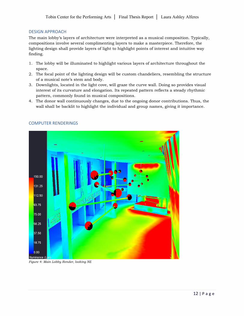
DESIGN APPROACH The main lobby’s layers of architecture were interpreted as a musical composition. Typically,
compositions involve several complimenting layers to make a masterpiece. Therefore, the
lighting design shall provide layers of light to highlight points of interest and intuitive way
finding.
1. The lobby will be illuminated to highlight various layers of architecture throughout the
space.
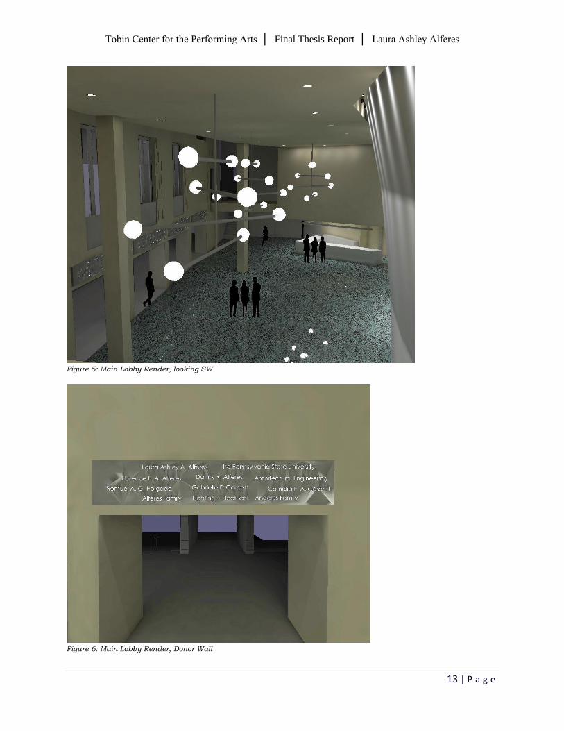
2. The focal point of the lighting design will be custom chandeliers, resembling the structure
of a musical note’s stem and body.
3. Downlights, located in the light cove, will graze the curve wall. Doing so provides visual
interest of its curvature and elongation. Its repeated pattern reflects a steady rhythmic
pattern, commonly found in musical compositions.
4. The donor wall continuously changes, due to the ongoing donor contributions. Thus, the
wall shall be backlit to highlight the individual and group names, giving it importance.
COMPUTER RENDERINGS
Figure 4: Main Lobby Render, looking NE
Tobin Center for the Performing Arts │ Final Thesis Report │ Laura Ashley Alferes
13 | P a g e
Figure 5: Main Lobby Render, looking SW
Figure 6: Main Lobby Render, Donor Wall
Tobin Center for the Performing Arts │ Final Thesis Report │ Laura Ashley Alferes
14 | P a g e
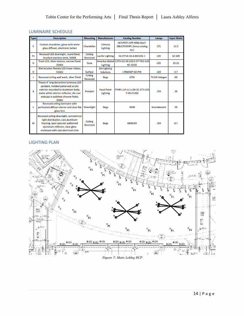
LUMINAIRE SCHEDULE
LIGHTING PLAN
Figure 7: Main Lobby RCP
Tobin Center for the Performing Arts │ Final Thesis Report │ Laura Ashley Alferes
15 | P a g e
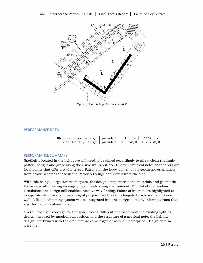
Figure 8: Main Lobby Concessions RCP
PERFORMANCE DATA
Illuminance level – target │ provided 100 lux │ 127.20 lux Power Density – target │ provided 2.00 W/ft2 │ 0.767 W/ft2
PERFORMANCE SUMMARY Spotlights located in the light cove will need to be aimed accordingly to give a clean rhythmic
pattern of light and graze along the curve wall’s surface. Custom “musical note” chandeliers are
focal points that offer visual interest. Patrons in the lobby can enjoy its geometric orientation
from below, whereas those in the Patron’s Lounge can view it from the side.
With this being a large transition space, the design complements the materials and geometric
features, while creating an engaging and welcoming environment. Mindful of the random
circulation, the design still enables intuitive way finding. Points of interest are highlighted to
exaggerate structural and meaningful purpose, such as the elongated curve wall and donor
wall. A flexible dimming system will be integrated into the design to subtly inform patrons that
a performance is about to begin.
Overall, the light redesign for the space took a different approach from the existing lighting
design. Inspired by musical composition and the structure of a musical note, the lighting
design intertwined with the architecture came together as one masterpiece. Design criteria
were met.
Tobin Center for the Performing Arts │ Final Thesis Report │ Laura Ashley Alferes
16 | P a g e
Patron’s Lounge ǀ special purpose space
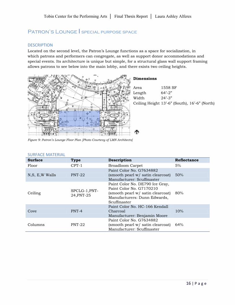
DESCRIPTION
Located on the second level, the Patron’s Lounge functions as a space for socialization, in
which patrons and performers can congregate, as well as support donor accommodations and
special events. Its architecture is unique but simple, for a structural glass wall support framing
allows patrons to see below into the main lobby, and there exists two ceiling heights.
Figure 9: Patron’s Lounge Floor Plan [Photo Courtesy of LMN Architects]
SURFACE MATERIAL Surface Type Description Reflectance
Floor CPT-1 Broadloom Carpet 5%
N,S, E,W Walls PNT-22 Paint Color No. G7634882 (smooth pearl w/ satin clearcoat) Manufacturer: Scuffmaster
50%
Ceiling SPCLG-1,PNT-24,PNT-25
Paint Color No. DE790 Ice Gray, Paint Color No. G7170210 (smooth pearl w/ satin clearcoat) Manufacturers: Dunn Edwards, Scuffmaster
80%
Cove PNT-4 Paint Color No. HC-166 Kendall Charcoal Manufacturer: Benjamin Moore
10%
Columns PNT-22 Paint Color No. G7634882 (smooth pearl w/ satin clearcoat) Manufacturer: Scuffmaster
64%
Dimensions
Area 1558 SF
Length 64’-2”
Width 24’-3”
Ceiling Height 13’-6” (South), 16’-6” (North)
Tobin Center for the Performing Arts │ Final Thesis Report │ Laura Ashley Alferes
17 | P a g e
DESIGN CRITERIA
Qualitative Criteria: The appropriate lighting for the Patron’s Lounge shall respond to its unique architectural
expression, and support the programmatic needs of the space to serve as a special retreat for
patrons. A control system is suitable for this space to permit various layers of lighting to be
zoned separately, allowing flexibility of the lighting system.
To reinforce the psychological impression of relaxation, the room should project a feeling of
comfort, conversation, and gathering. In accordance to John Flynn’s lighting mode and
subjective impression of relaxation, such factors are fitting for this type of space:
Non-uniform peripheral lighting,
Lower light levels
Warmer-toned light sources
IES suggested very important criteria:
Modeling of faces and objects
IES suggested important criteria:
System control and flexibility
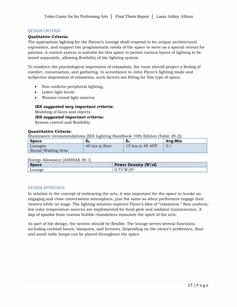
Quantitative Criteria: Illuminance recommendations [IES Lighting Handbook 10th Edition (Table 28.2)]
Space Eh Ev Avg:Min
Lounges Social/Waiting Area
40 lux @ floor 15 lux @ 4ft AFF 2:1
Energy Allowance [ASHRAE 90.1]
Space Power Density (W/sf)
Lounge 0.73 W/ft2
DESIGN APPROACH In relation to the concept of embracing the arts, it was important for the space to invoke an
engaging and close conversation atmosphere, just the same as when performers engage their
viewers while on stage. The lighting solution explores Flynn’s idea of “relaxation.” Non-uniform,
low color temperature sources are implemented for focal glow and ambient luminescence. A
dap of sparkle from custom bubble chandeliers stimulate the spirit of the arts.
As part of the design, the system should be flexible. The lounge serves several functions,
including cocktail hours, banquets, and lectures. Depending on the owner’s preference, floor
and small table lamps can be placed throughout the space.
Tobin Center for the Performing Arts │ Final Thesis Report │ Laura Ashley Alferes
18 | P a g e
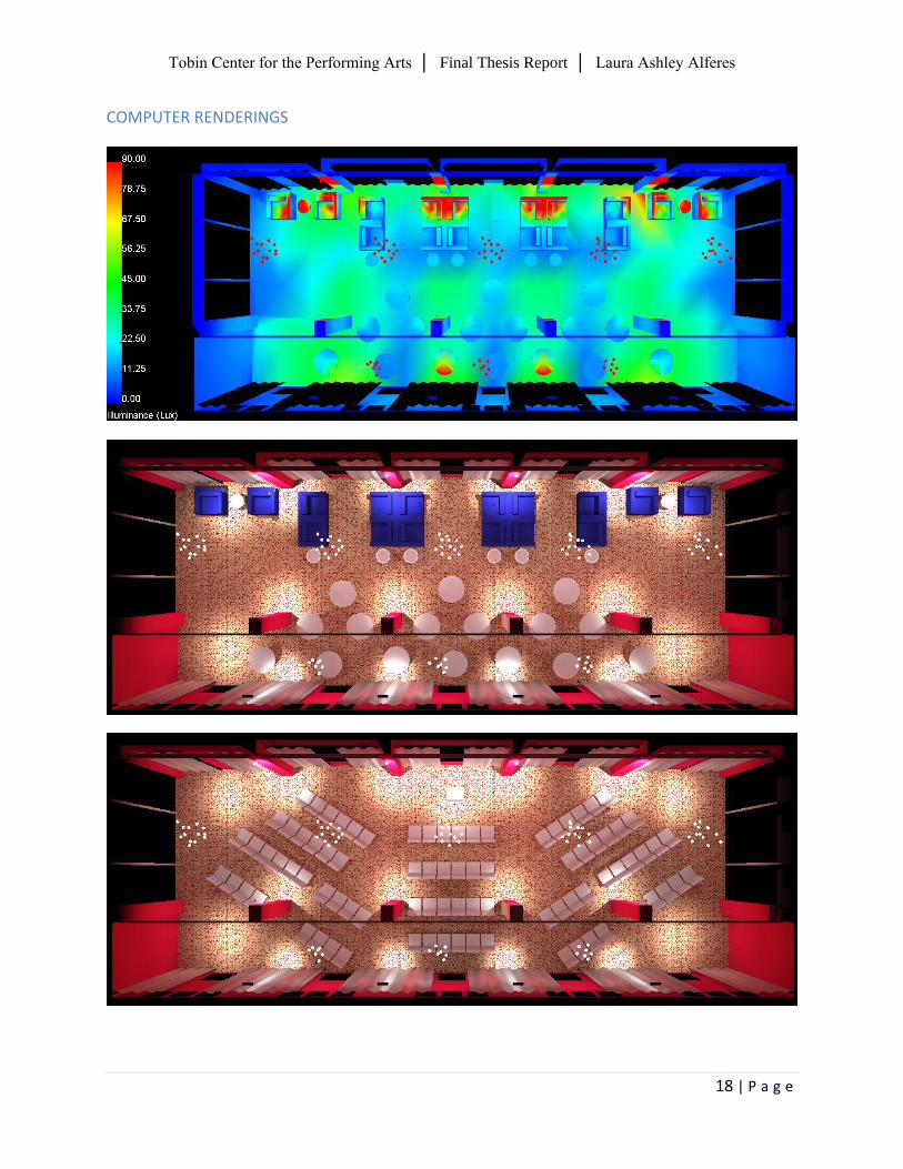
COMPUTER RENDERINGS
Tobin Center for the Performing Arts │ Final Thesis Report │ Laura Ashley Alferes
19 | P a g e
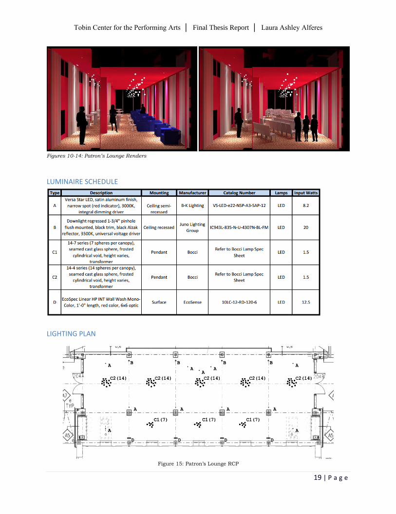
Figures 10-14: Patron’s Lounge Renders
LUMINAIRE SCHEDULE
LIGHTING PLAN
Figure 15: Patron’s Lounge RCP
Tobin Center for the Performing Arts │ Final Thesis Report │ Laura Ashley Alferes
20 | P a g e
PERFORMANCE DATA
Illuminance level – target │ provided 40 lux│41.4 lux Power Density – target │ provided 0.73 W/ft2│0.22 W/ft2
PERFORMANCE SUMMARY The lighting redesign was successful in an attempt to explore the Flynn mode of “relaxation”
and Richard Kelly’s three elements of light: (1) focal glow, (2) ambient luminescence and (3)
play of brilliance.
Custom bubble chandeliers have pinpoints of light placed in glass spheres at varying heights.
With a glass material, the light contributes to the subtle general illumination of the space in all
directions. Columns were lit to reassure safe movement around them, especially since this
space is meant for continuous socializing.
The system is flexible due to various uses, including cocktail hours, banquets and lectures. For
the purpose of cocktail and banquet functions, seating and standing areas are not illuminated
directly. This was intended for the possible placement of floor or table lamps and to encourage
close conversation amongst individuals. The lecture layout, however, has the podium
illuminated by adjustable downlights directed towards the speaker.
Overall, the lighting redesign achieved both performance purpose and design criteria. The
space serves as a retreat for patrons. Inspired by the concept of embracing the arts, patrons
become engaged with one another, similar to performers engaging their audience.
Tobin Center for the Performing Arts │ Final Thesis Report │ Laura Ashley Alferes
21 | P a g e
Main Auditorium ǀ large work space
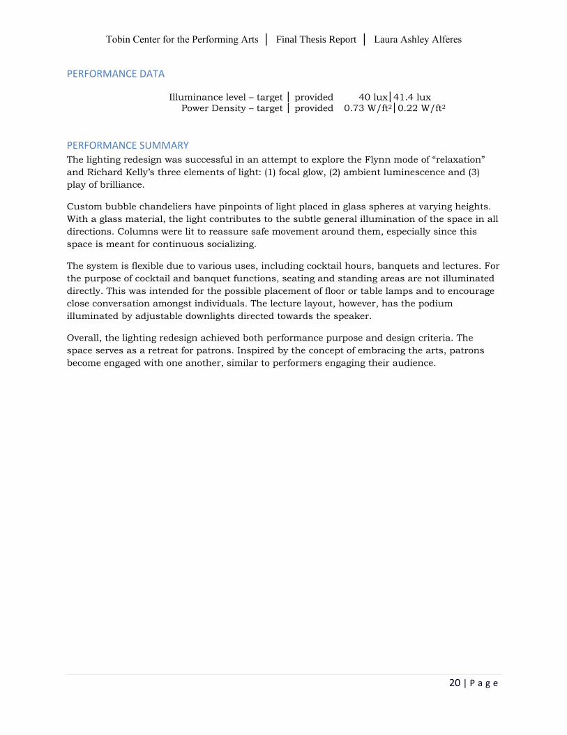
DESCRIPTION
The main auditorium is located in the center of the building program, and can house 1,750
audience members. It is a suitable venue space for multiple productions, such as theatrical
productions, orchestral concerts, dance performances, films, amplified events, and lectures.
Figure 16: Main Auditorium Floor Plan [Photo Courtesy of LMN Architects]
SURFACE MATERIAL Surface Type Description Reflectance
Floor CPT-2 Modular Tile Carpet 20%
N, S, E, W Walls
PNT-17 Paint Color No. DEA 146 Scarlet Apple Manufacturer: Dunn Edwards
20%
Ceiling PNT-21 Paint Color No. DEA 195 Primitive Plum Manufacturer: Dunn Edwards
20%
DESIGN CRITERIA
Qualitative Criteria:
It is necessary for the architectural lighting to be flexible, in order to respond to various
lighting and rigging requirements. The control system should have performance-quality
dimming, allowing for a smooth and continuous dimming from full output to extreme low
output and vice versa. Without quality dimming ability, abrupt lighting changes and unsettling
color shifts will occur.
It is critical for aisle, step, and seat lighting to meet safety requirements. Audience members
should be able to safely and conveniently access into and out of the auditorium at all times.
Dimensions
Area 11,648 SF
Length 176.17’-0”
Width 92.01’-0”
Ceiling Height 88’-0”
Tobin Center for the Performing Arts │ Final Thesis Report │ Laura Ashley Alferes
22 | P a g e
IES suggested very important criteria:
Modeling of faces and objects
Color appearance and contrast
IES suggested important criteria:
System control and flexibility
Quantitative Criteria: Illuminance recommendations [IES Lighting Handbook 10th Edition (Table 28.2)]
Space Eh Ev Avg:Min
Audience – during production
2 lux @ floor 1 lux @ 5ft AFF 2:1
Audience – pre/post show, intermission
100 lux @ floor 30 lux @ 5ft AFF 2:1
Circulation – during production
2 lux @ floor 4 lux @ 5ft AFF 5:1
Circulation – pre/post show, intermission
100 lux @ floor 30 lux @ 5ft AFF 2:1
Energy Allowance [ASHRAE 90.1]
Space Power Density (W/sf)
Auditorium/Seating Area – Permanent (for Performing Arts Theater)
2.43 W/ft2
Decorative Allowance 1.00 W/ft2
DESIGN APPROACH In order to incorporate the concept of embracing the arts, it was ideal to connect the concept of
musical composition from the lobby into the main auditorium. To recall, the main lobby has
points of interest that resemble musical notes and motifs, which contributes to a composition.
The main auditorium shall complete the masterpiece by including linear luminaires recessed
into the balcony fascia. These represent the grand bar staff, which are bar lines that musical
notes are placed. This encourages audience members to observe the simplicity of horseshoe
architecture. More importantly, the balcony lighting draws the eye towards the stage.
Due to the space having a multipurpose nature, the lighting solution shall be visually pleasing
and comfortable for occupants. It is essential to have a flexible, performance-quality dimming
and preset scene control system. Not only does this address the variable purposes, but it also
will meet way finding requirements before, during and after a performance.
Tobin Center for the Performing Arts │ Final Thesis Report │ Laura Ashley Alferes
23 | P a g e
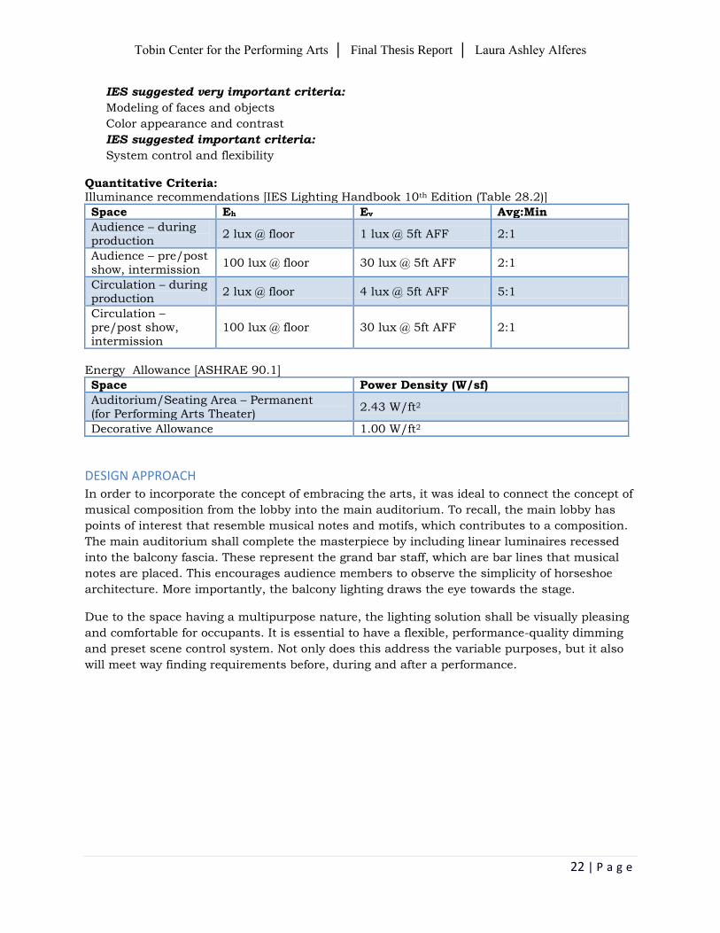
COMPUTER RENDERINGS
Tobin Center for the Performing Arts │ Final Thesis Report │ Laura Ashley Alferes
24 | P a g e
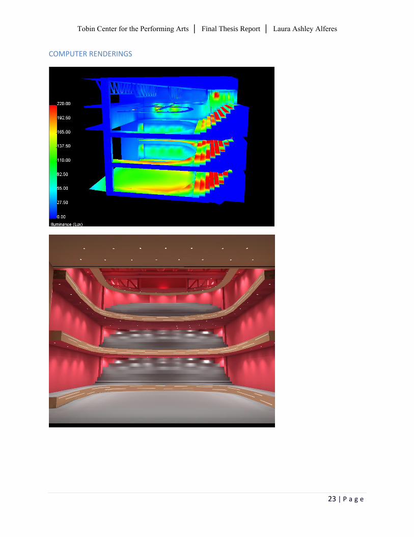
Figures 17-19: Patron’s Lounge Renders
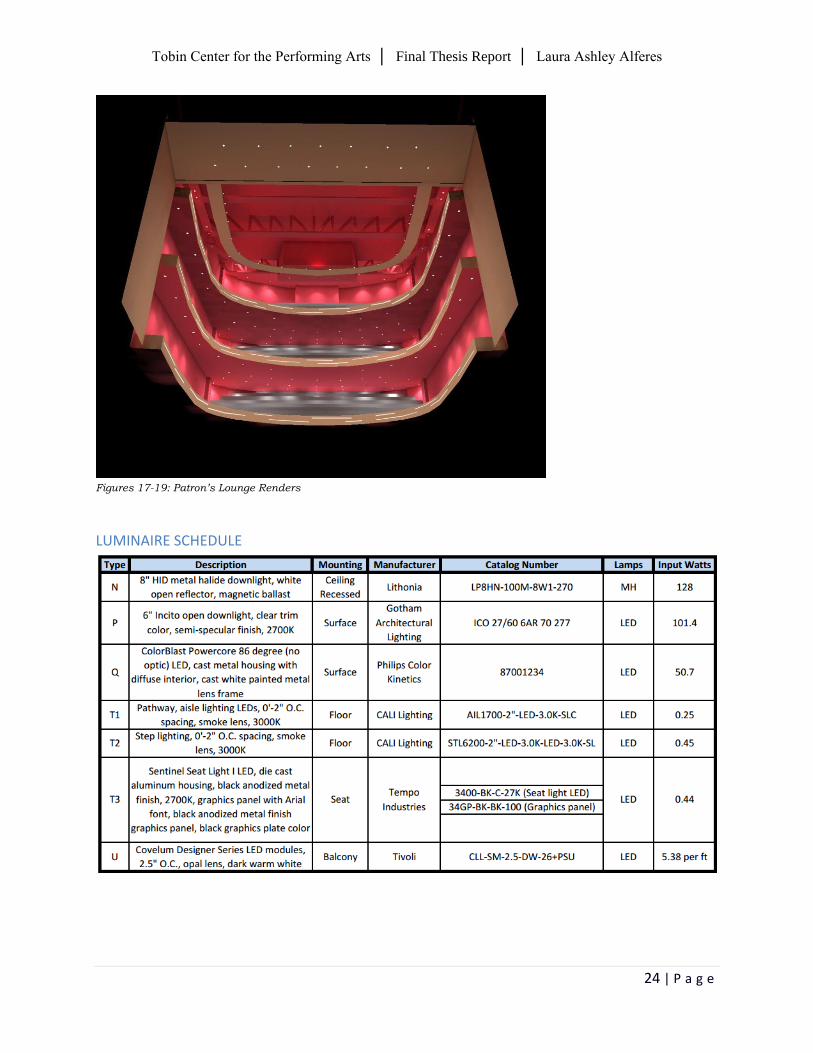
LUMINAIRE SCHEDULE
Tobin Center for the Performing Arts │ Final Thesis Report │ Laura Ashley Alferes
25 | P a g e
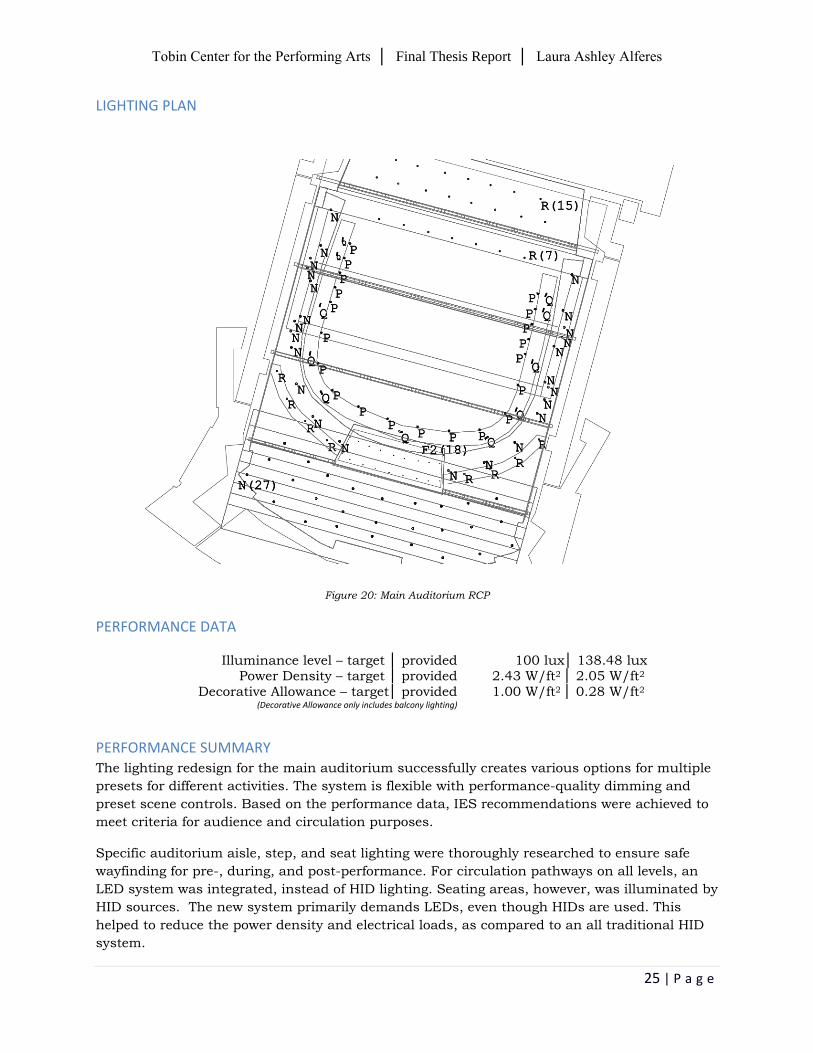
LIGHTING PLAN
Figure 20: Main Auditorium RCP
PERFORMANCE DATA
Illuminance level – target │ provided 100 lux│ 138.48 lux Power Density – target │ provided 2.43 W/ft2 │ 2.05 W/ft2
Decorative Allowance – target│ provided 1.00 W/ft2 │ 0.28 W/ft2 (Decorative Allowance only includes balcony lighting)
PERFORMANCE SUMMARY The lighting redesign for the main auditorium successfully creates various options for multiple
presets for different activities. The system is flexible with performance-quality dimming and
preset scene controls. Based on the performance data, IES recommendations were achieved to
meet criteria for audience and circulation purposes.
Specific auditorium aisle, step, and seat lighting were thoroughly researched to ensure safe
wayfinding for pre-, during, and post-performance. For circulation pathways on all levels, an
LED system was integrated, instead of HID lighting. Seating areas, however, was illuminated by
HID sources. The new system primarily demands LEDs, even though HIDs are used. This
helped to reduce the power density and electrical loads, as compared to an all traditional HID
system.
Tobin Center for the Performing Arts │ Final Thesis Report │ Laura Ashley Alferes
26 | P a g e
Event Plaza ǀ outdoor space
DESCRIPTION
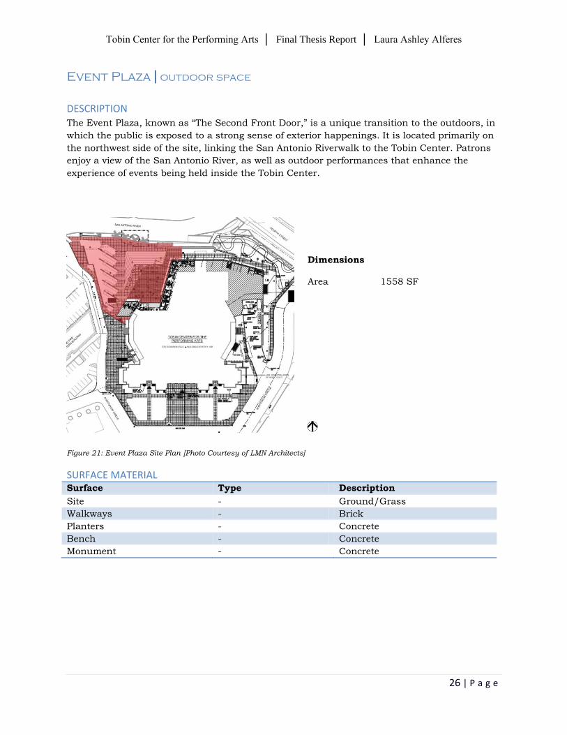
The Event Plaza, known as “The Second Front Door,” is a unique transition to the outdoors, in
which the public is exposed to a strong sense of exterior happenings. It is located primarily on
the northwest side of the site, linking the San Antonio Riverwalk to the Tobin Center. Patrons
enjoy a view of the San Antonio River, as well as outdoor performances that enhance the
experience of events being held inside the Tobin Center.
Figure 21: Event Plaza Site Plan [Photo Courtesy of LMN Architects]
SURFACE MATERIAL
Surface Type Description
Site - Ground/Grass
Walkways - Brick
Planters - Concrete
Bench - Concrete
Monument - Concrete
Dimensions
Area 1558 SF
Tobin Center for the Performing Arts │ Final Thesis Report │ Laura Ashley Alferes
27 | P a g e
DESIGN CRITERIA
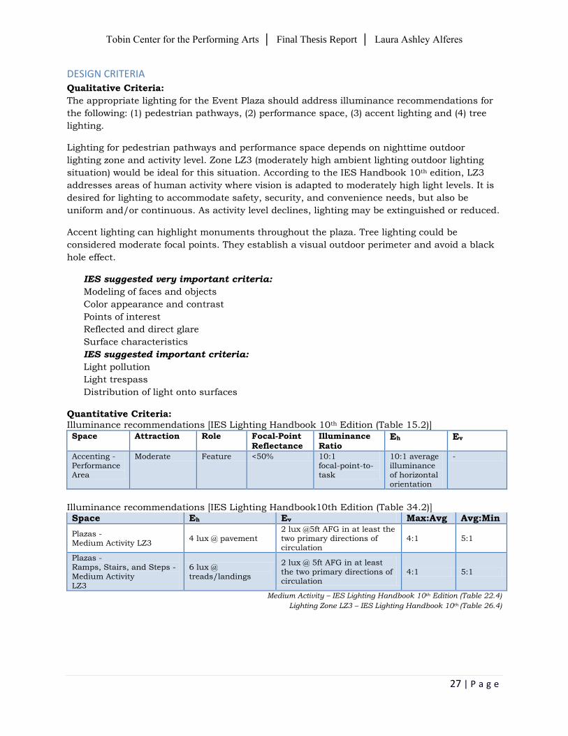
Qualitative Criteria:
The appropriate lighting for the Event Plaza should address illuminance recommendations for
the following: (1) pedestrian pathways, (2) performance space, (3) accent lighting and (4) tree
lighting.
Lighting for pedestrian pathways and performance space depends on nighttime outdoor
lighting zone and activity level. Zone LZ3 (moderately high ambient lighting outdoor lighting
situation) would be ideal for this situation. According to the IES Handbook 10th edition, LZ3
addresses areas of human activity where vision is adapted to moderately high light levels. It is
desired for lighting to accommodate safety, security, and convenience needs, but also be
uniform and/or continuous. As activity level declines, lighting may be extinguished or reduced.
Accent lighting can highlight monuments throughout the plaza. Tree lighting could be
considered moderate focal points. They establish a visual outdoor perimeter and avoid a black
hole effect.
IES suggested very important criteria:
Modeling of faces and objects
Color appearance and contrast
Points of interest
Reflected and direct glare
Surface characteristics
IES suggested important criteria:
Light pollution
Light trespass
Distribution of light onto surfaces
Quantitative Criteria: Illuminance recommendations [IES Lighting Handbook 10th Edition (Table 15.2)]
Space Attraction Role Focal-Point Reflectance
Illuminance Ratio
Eh Ev
Accenting - Performance Area
Moderate Feature <50% 10:1 focal-point-to-task
10:1 average illuminance of horizontal orientation
-
Illuminance recommendations [IES Lighting Handbook10th Edition (Table 34.2)] Space Eh Ev Max:Avg Avg:Min
Plazas - Medium Activity LZ3
4 lux @ pavement 2 lux @5ft AFG in at least the two primary directions of circulation
4:1 5:1
Plazas - Ramps, Stairs, and Steps - Medium Activity LZ3
6 lux @ treads/landings
2 lux @ 5ft AFG in at least the two primary directions of circulation
4:1 5:1
Medium Activity – IES Lighting Handbook 10th Edition (Table 22.4)
Lighting Zone LZ3 – IES Lighting Handbook 10th (Table 26.4)
Tobin Center for the Performing Arts │ Final Thesis Report │ Laura Ashley Alferes
28 | P a g e
Energy Allowance [ASHRAE Standard 90.1] Space Power Density (W/sf)
Plaza Areas - Walkways 10ft wide or greater
0.16 W/ft2
Stairways 1.0 W/ft2
Landscaping 0.05 W/ft2
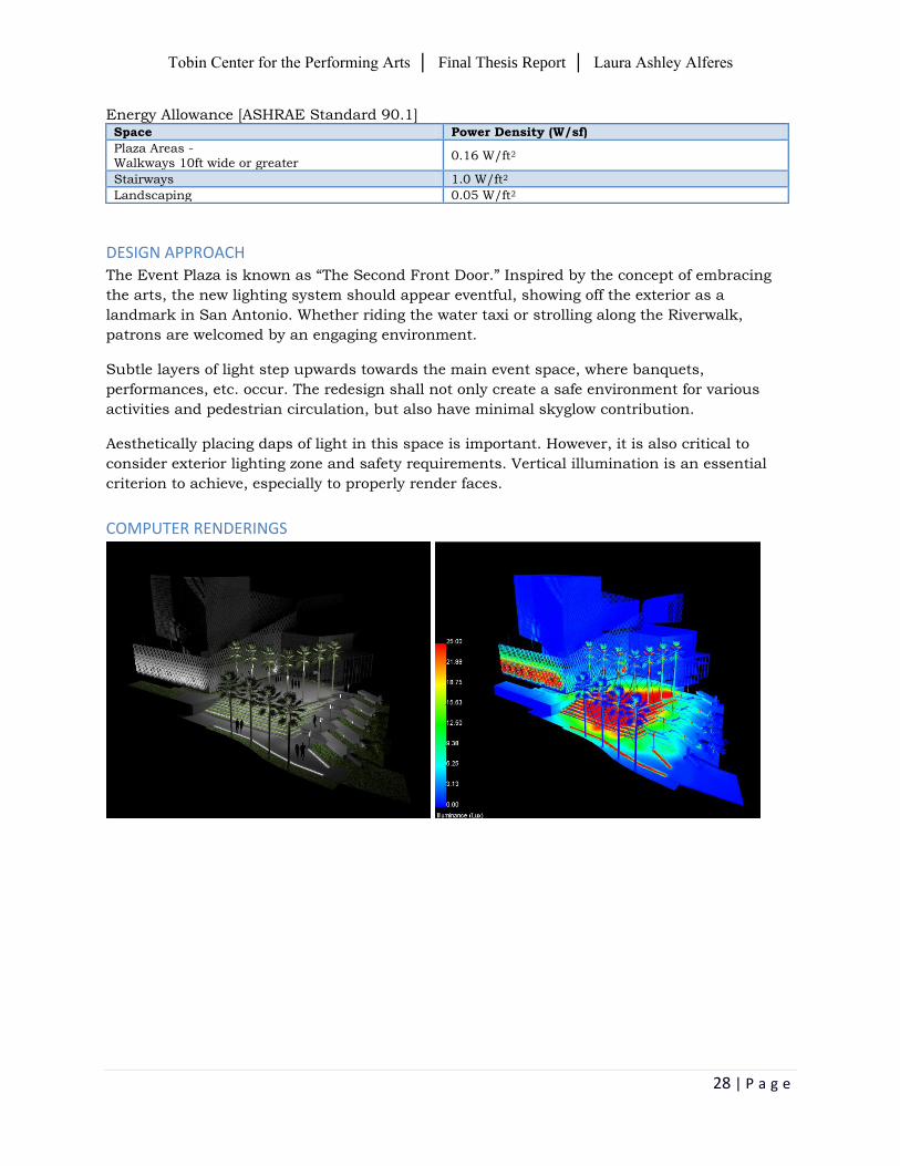
DESIGN APPROACH The Event Plaza is known as “The Second Front Door.” Inspired by the concept of embracing
the arts, the new lighting system should appear eventful, showing off the exterior as a
landmark in San Antonio. Whether riding the water taxi or strolling along the Riverwalk,
patrons are welcomed by an engaging environment.
Subtle layers of light step upwards towards the main event space, where banquets,
performances, etc. occur. The redesign shall not only create a safe environment for various
activities and pedestrian circulation, but also have minimal skyglow contribution.
Aesthetically placing daps of light in this space is important. However, it is also critical to
consider exterior lighting zone and safety requirements. Vertical illumination is an essential
criterion to achieve, especially to properly render faces.
COMPUTER RENDERINGS
Tobin Center for the Performing Arts │ Final Thesis Report │ Laura Ashley Alferes
29 | P a g e
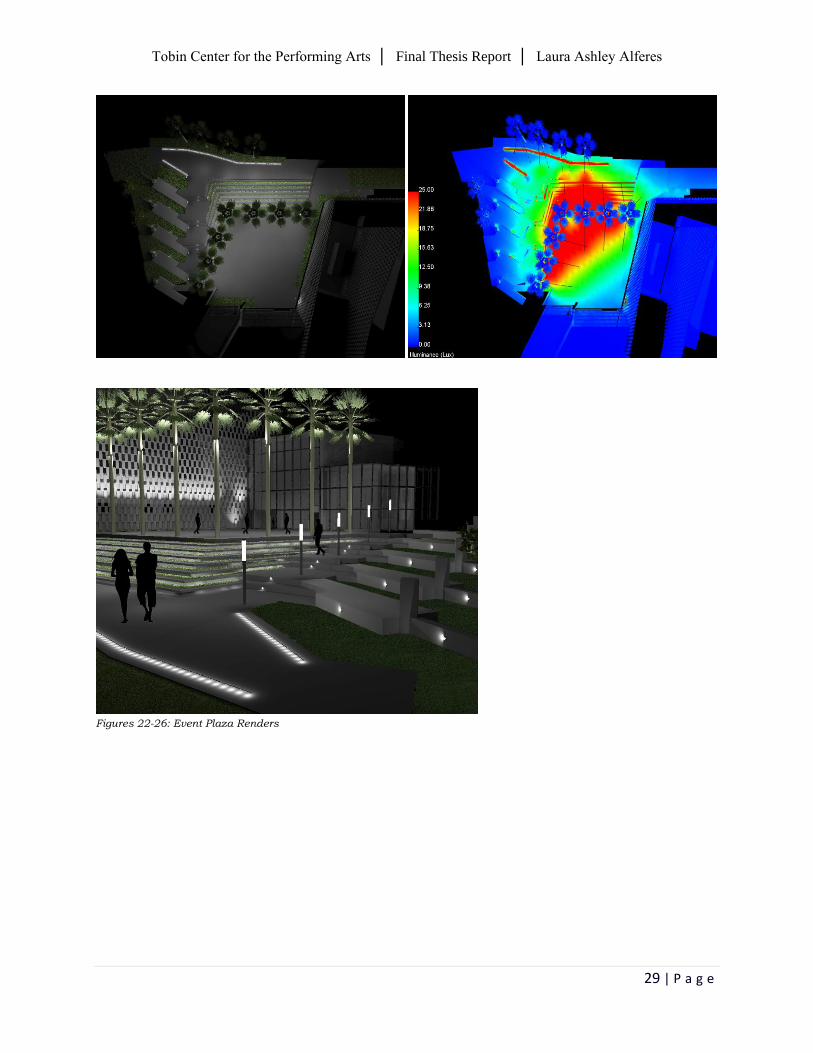
Figures 22-26: Event Plaza Renders
Tobin Center for the Performing Arts │ Final Thesis Report │ Laura Ashley Alferes
30 | P a g e
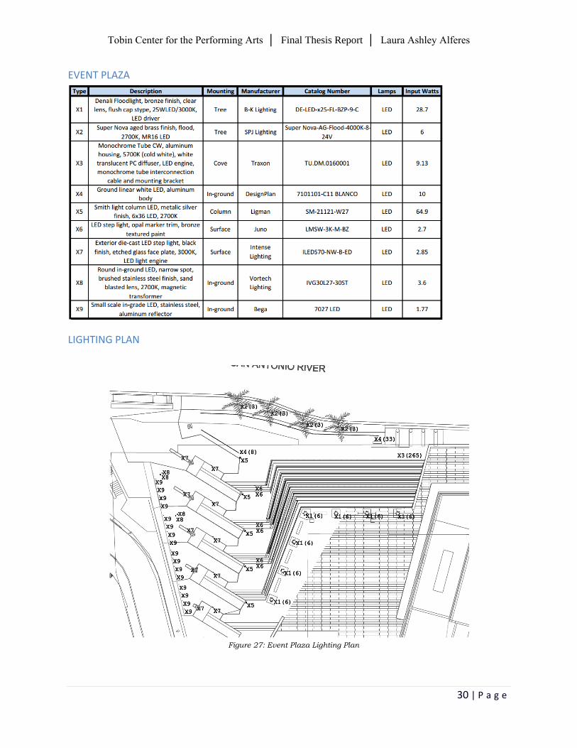
EVENT PLAZA
LIGHTING PLAN
Figure 27: Event Plaza Lighting Plan
Tobin Center for the Performing Arts │ Final Thesis Report │ Laura Ashley Alferes
31 | P a g e
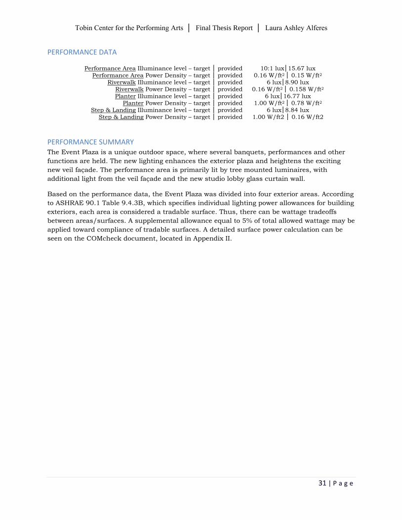
PERFORMANCE DATA
Performance Area Illuminance level – target │ provided 10:1 lux│15.67 lux
Performance Area Power Density – target │ provided 0.16 W/ft2 │ 0.15 W/ft2 Riverwalk Illuminance level – target │ provided 6 lux│8.90 lux
Riverwalk Power Density – target │ provided 0.16 W/ft2 │ 0.158 W/ft2 Planter Illuminance level – target │ provided 6 lux│16.77 lux
Planter Power Density – target │ provided 1.00 W/ft2 │ 0.78 W/ft2 Step & Landing Illuminance level – target │ provided 6 lux│8.84 lux
Step & Landing Power Density – target │ provided 1.00 W/ft2 │ 0.16 W/ft2
PERFORMANCE SUMMARY The Event Plaza is a unique outdoor space, where several banquets, performances and other
functions are held. The new lighting enhances the exterior plaza and heightens the exciting
new veil façade. The performance area is primarily lit by tree mounted luminaires, with
additional light from the veil façade and the new studio lobby glass curtain wall.
Based on the performance data, the Event Plaza was divided into four exterior areas. According
to ASHRAE 90.1 Table 9.4.3B, which specifies individual lighting power allowances for building
exteriors, each area is considered a tradable surface. Thus, there can be wattage tradeoffs
between areas/surfaces. A supplemental allowance equal to 5% of total allowed wattage may be
applied toward compliance of tradable surfaces. A detailed surface power calculation can be
seen on the COMcheck document, located in Appendix II.
Tobin Center for the Performing Arts │ Final Thesis Report │ Laura Ashley Alferes
32 | P a g e
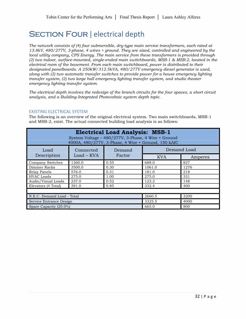
Section Four ǀ electrical depth
The network consists of (4) four submersible, dry-type main service transformers, each rated at 13.8kV, 480/277V, 3-phase, 4 wires + ground. They are sized, controlled and engineered by the local utility company, CPS Energy. The main service from these transformers is provided through (2) two indoor, surface-mounted, single-ended main switchboards, MSB-1 & MSB-2, located in the electrical room of the basement. From each main switchboard, power is distributed to their designated panelboards. A 250kW/312.5kVA, 480/277V emergency diesel generator is used, along with (2) two automatic transfer switches to provide power for a house emergency lighting transfer system, (2) two large hall emergency lighting transfer system, and studio theater emergency lighting transfer system.
The electrical depth involves the redesign of the branch circuits for the four spaces, a short circuit analysis, and a Building-Integrated Photovoltaic system depth topic.
EXISTING ELECTRICAL SYSTEM The following is an overview of the original electrical system. Two main switchboards, MSB-1 and MSB-2, exist. The actual connected building load analysis is as follows:
Electrical Load Analysis: MSB-1 System Voltage – 480/277V, 3-Phase, 4 Wire + Ground 4000A, 480/277V, 3-Phase, 4 Wire + Ground, 150 kAIC
Load Description
Connected Load – KVA
Demand Factor
Demand Load
KVA Amperes
Company Switches 1260.0 0.55 688.0 827
Dimmer Racks 3500.0 0.30 1061.0 1276
Relay Panels 576.0 0.31 181.0 218
HVAC Loads 275.0 1.00 275.0 331
Audio/Visual Loads 237.0 0.52 123.2 148
Elevators (4 Total) 391.0 0.85 332.4 400
N.E.C. Demand Load - Total 2660.5 3200
Service Entrance Design 3325.5 4000
Spare Capacity (20.0%) 665.0 800
Tobin Center for the Performing Arts │ Final Thesis Report │ Laura Ashley Alferes
33 | P a g e
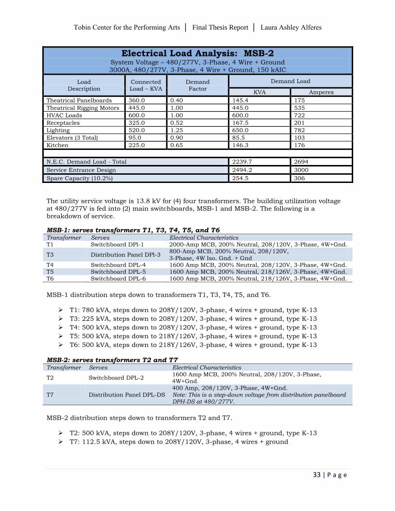
Electrical Load Analysis: MSB-2 System Voltage – 480/277V, 3-Phase, 4 Wire + Ground 3000A, 480/277V, 3-Phase, 4 Wire + Ground, 150 kAIC
Load Description
Connected Load – KVA
Demand Factor
Demand Load
KVA Amperes
Theatrical Panelboards 360.0 0.40 145.4 175
Theatrical Rigging Motors 445.0 1.00 445.0 535
HVAC Loads 600.0 1.00 600.0 722
Receptacles 325.0 0.52 167.5 201
Lighting 520.0 1.25 650.0 782
Elevators (3 Total) 95.0 0.90 85.5 103
Kitchen 225.0 0.65 146.3 176
N.E.C. Demand Load - Total 2239.7 2694
Service Entrance Design 2494.2 3000
Spare Capacity (10.2%) 254.5 306
The utility service voltage is 13.8 kV for (4) four transformers. The building utilization voltage at 480/277V is fed into (2) main switchboards, MSB-1 and MSB-2. The following is a breakdown of service.
MSB-1: serves transformers T1, T3, T4, T5, and T6
Transformer Serves Electrical Characteristics T1 Switchboard DPl-1 2000-Amp MCB, 200% Neutral, 208/120V, 3-Phase, 4W+Gnd.
T3 Distribution Panel DPl-3 800-Amp MCB, 200% Neutral, 208/120V, 3-Phase, 4W Iso. Gnd. + Gnd
T4 Switchboard DPL-4 1600 Amp MCB, 200% Neutral, 208/120V, 3-Phase, 4W+Gnd. T5 Switchboard DPL-5 1600 Amp MCB, 200% Neutral, 218/126V, 3-Phase, 4W+Gnd. T6 Switchboard DPL-6 1600 Amp MCB, 200% Neutral, 218/126V, 3-Phase, 4W+Gnd.
MSB-1 distribution steps down to transformers T1, T3, T4, T5, and T6.
T1: 780 kVA, steps down to 208Y/120V, 3-phase, 4 wires + ground, type K-13
T3: 225 kVA, steps down to 208Y/120V, 3-phase, 4 wires + ground, type K-13
T4: 500 kVA, steps down to 208Y/120V, 3-phase, 4 wires + ground, type K-13
T5: 500 kVA, steps down to 218Y/126V, 3-phase, 4 wires + ground, type K-13
T6: 500 kVA, steps down to 218Y/126V, 3-phase, 4 wires + ground, type K-13
MSB-2: serves transformers T2 and T7 Transformer Serves Electrical Characteristics
T2 Switchboard DPL-2 1600 Amp MCB, 200% Neutral, 208/120V, 3-Phase, 4W+Gnd.
T7 Distribution Panel DPL-DS 400 Amp, 208/120V, 3-Phase, 4W+Gnd. Note: This is a step-down voltage from distribution panelboard DPH-DS at 480/277V.
MSB-2 distribution steps down to transformers T2 and T7.
T2: 500 kVA, steps down to 208Y/120V, 3-phase, 4 wires + ground, type K-13
T7: 112.5 kVA, steps down to 208Y/120V, 3-phase, 4 wires + ground
Tobin Center for the Performing Arts │ Final Thesis Report │ Laura Ashley Alferes
34 | P a g e
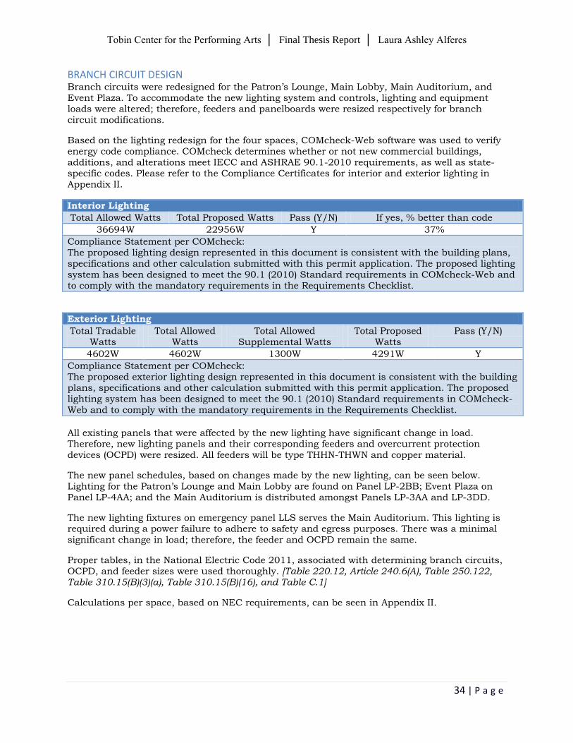
BRANCH CIRCUIT DESIGN Branch circuits were redesigned for the Patron’s Lounge, Main Lobby, Main Auditorium, and Event Plaza. To accommodate the new lighting system and controls, lighting and equipment loads were altered; therefore, feeders and panelboards were resized respectively for branch circuit modifications.
Based on the lighting redesign for the four spaces, COMcheck-Web software was used to verify energy code compliance. COMcheck determines whether or not new commercial buildings, additions, and alterations meet IECC and ASHRAE 90.1-2010 requirements, as well as state-specific codes. Please refer to the Compliance Certificates for interior and exterior lighting in Appendix II.
Interior Lighting
Total Allowed Watts Total Proposed Watts Pass (Y/N) If yes, % better than code
36694W 22956W Y 37%
Compliance Statement per COMcheck: The proposed lighting design represented in this document is consistent with the building plans, specifications and other calculation submitted with this permit application. The proposed lighting system has been designed to meet the 90.1 (2010) Standard requirements in COMcheck-Web and to comply with the mandatory requirements in the Requirements Checklist.
Exterior Lighting
Total Tradable Watts
Total Allowed Watts
Total Allowed Supplemental Watts
Total Proposed Watts
Pass (Y/N)
4602W 4602W 1300W 4291W Y
Compliance Statement per COMcheck: The proposed exterior lighting design represented in this document is consistent with the building plans, specifications and other calculation submitted with this permit application. The proposed lighting system has been designed to meet the 90.1 (2010) Standard requirements in COMcheck-Web and to comply with the mandatory requirements in the Requirements Checklist.
All existing panels that were affected by the new lighting have significant change in load. Therefore, new lighting panels and their corresponding feeders and overcurrent protection devices (OCPD) were resized. All feeders will be type THHN-THWN and copper material.
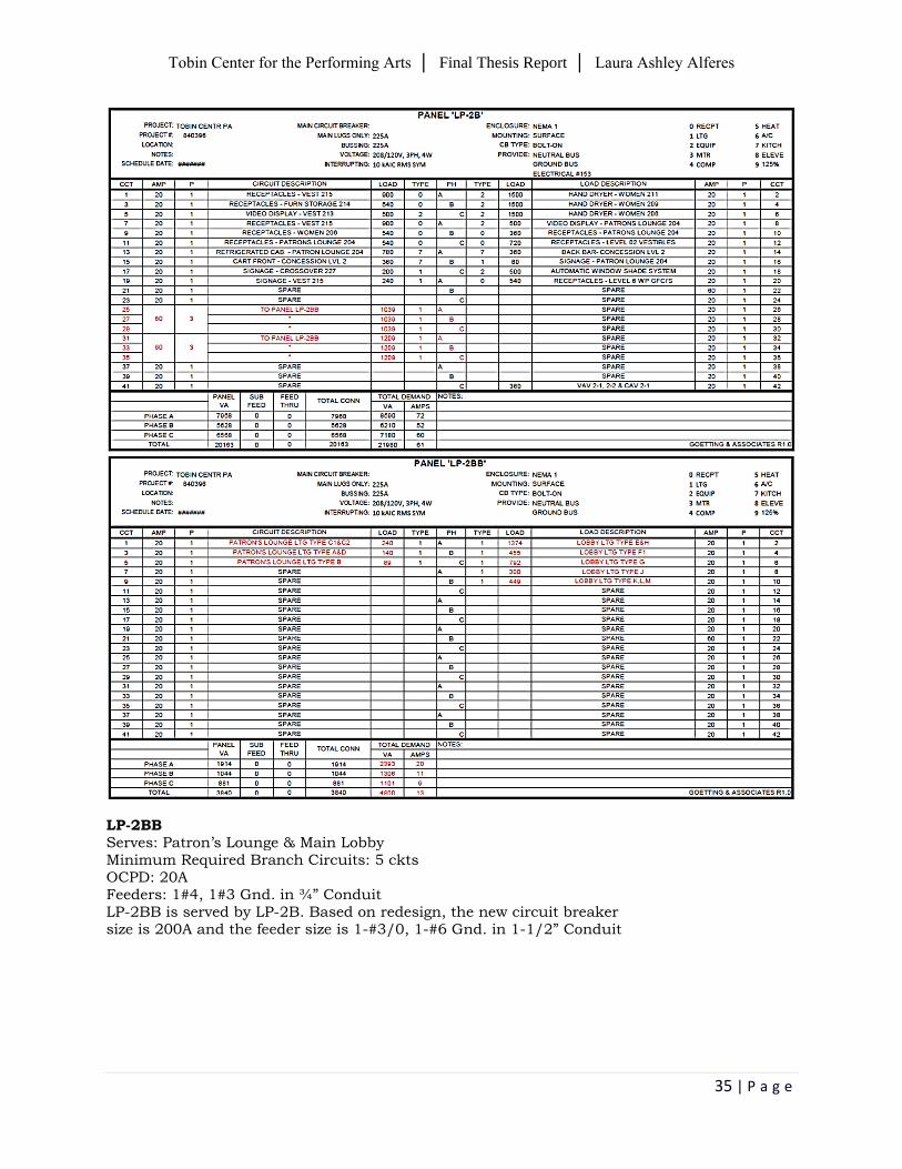
The new panel schedules, based on changes made by the new lighting, can be seen below. Lighting for the Patron’s Lounge and Main Lobby are found on Panel LP-2BB; Event Plaza on Panel LP-4AA; and the Main Auditorium is distributed amongst Panels LP-3AA and LP-3DD.
The new lighting fixtures on emergency panel LLS serves the Main Auditorium. This lighting is required during a power failure to adhere to safety and egress purposes. There was a minimal significant change in load; therefore, the feeder and OCPD remain the same.
Proper tables, in the National Electric Code 2011, associated with determining branch circuits, OCPD, and feeder sizes were used thoroughly. [Table 220.12, Article 240.6(A), Table 250.122, Table 310.15(B)(3)(a), Table 310.15(B)(16), and Table C.1]
Calculations per space, based on NEC requirements, can be seen in Appendix II.
Tobin Center for the Performing Arts │ Final Thesis Report │ Laura Ashley Alferes
35 | P a g e
LP-2BB Serves: Patron’s Lounge & Main Lobby Minimum Required Branch Circuits: 5 ckts OCPD: 20A Feeders: 1#4, 1#3 Gnd. in ¾” Conduit LP-2BB is served by LP-2B. Based on redesign, the new circuit breaker size is 200A and the feeder size is 1-#3/0, 1-#6 Gnd. in 1-1/2” Conduit
Tobin Center for the Performing Arts │ Final Thesis Report │ Laura Ashley Alferes
36 | P a g e
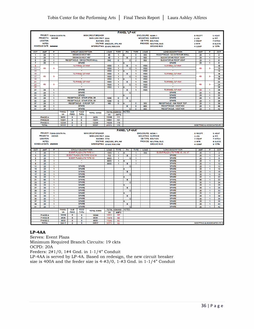
LP-4AA Serves: Event Plaza Minimum Required Branch Circuits: 19 ckts OCPD: 20A Feeders: 2#1/0, 1#4 Gnd. in 1-1/4” Conduit LP-4AA is served by LP-4A. Based on redesign, the new circuit breaker size is 400A and the feeder size is 4-#3/0, 1-#3 Gnd. in 1-1/4” Conduit
Tobin Center for the Performing Arts │ Final Thesis Report │ Laura Ashley Alferes
37 | P a g e
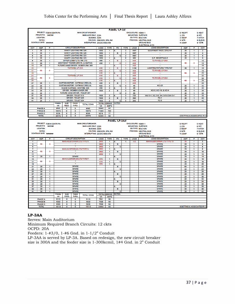
LP-3AA Serves: Main Auditorium Minimum Required Branch Circuits: 12 ckts OCPD: 20A Feeders: 1-#3/0, 1-#6 Gnd. in 1-1/2” Conduit LP-3AA is served by LP-3A. Based on redesign, the new circuit breaker size is 300A and the feeder size is 1-300kcmil, 1#4 Gnd. in 2” Conduit
Tobin Center for the Performing Arts │ Final Thesis Report │ Laura Ashley Alferes
38 | P a g e
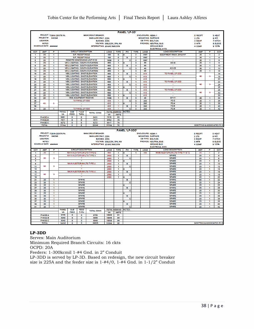
LP-3DD Serves: Main Auditorium Minimum Required Branch Circuits: 16 ckts OCPD: 20A Feeders: 1-300kcmil 1-#4 Gnd. in 2” Conduit LP-3DD is served by LP-3D. Based on redesign, the new circuit breaker size is 225A and the feeder size is 1-#4/0, 1-#4 Gnd. in 1-1/2” Conduit
Tobin Center for the Performing Arts │ Final Thesis Report │ Laura Ashley Alferes
39 | P a g e
Added lighting panels can be seen in a revised single line diagram in Appendix II.
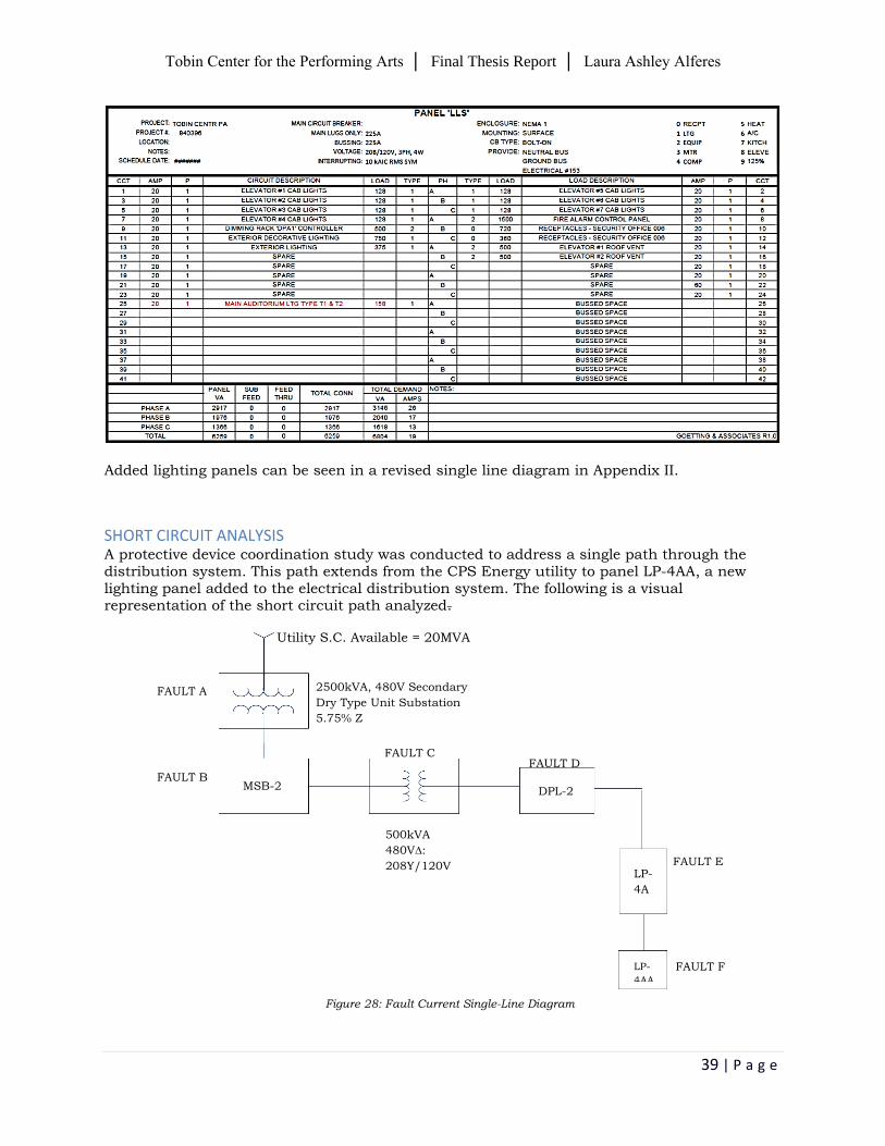
SHORT CIRCUIT ANALYSIS A protective device coordination study was conducted to address a single path through the distribution system. This path extends from the CPS Energy utility to panel LP-4AA, a new lighting panel added to the electrical distribution system. The following is a visual representation of the short circuit path analyzed.
Figure 28: Fault Current Single-Line Diagram
MSB-2 DPL-2
LP-
4A
LP-
4AA
FAULT A
FAULT B
FAULT C FAULT D
FAULT E
FAULT F
Utility S.C. Available = 20MVA
2500kVA, 480V Secondary
Dry Type Unit Substation
5.75% Z
500kVA
480V∆:
208Y/120V
Tobin Center for the Performing Arts │ Final Thesis Report │ Laura Ashley Alferes
40 | P a g e
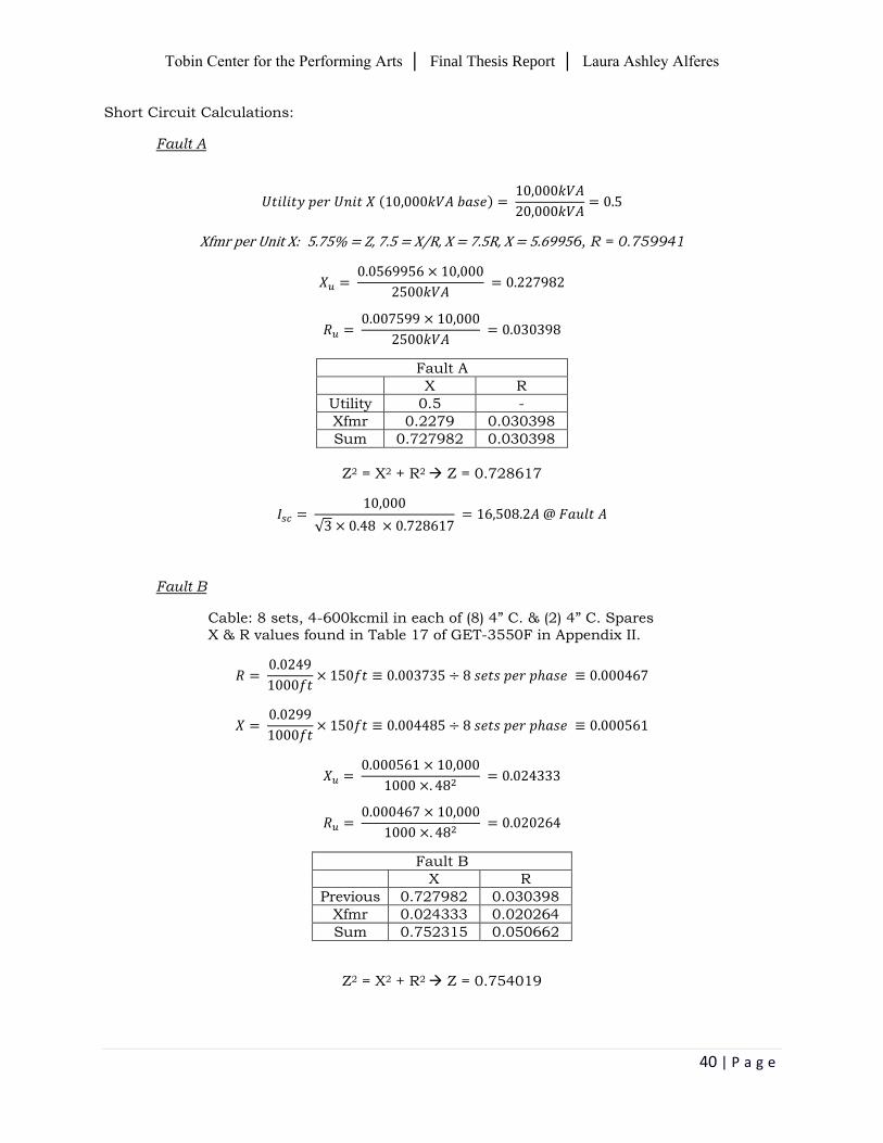
Short Circuit Calculations:
Fault A
( )
Xfmr per Unit X: 5.75% = Z, 7.5 = X/R, X = 7.5R, X = 5.69956, R = 0.759941
Fault A
X R
Utility 0.5 -
Xfmr 0.2279 0.030398
Sum 0.727982 0.030398
Z2 = X2 + R2 Z = 0.728617
√
Fault B
Cable: 8 sets, 4-600kcmil in each of (8) 4” C. & (2) 4” C. Spares X & R values found in Table 17 of GET-3550F in Appendix II.
Fault B
X R
Previous 0.727982 0.030398
Xfmr 0.024333 0.020264
Sum 0.752315 0.050662
Z2 = X2 + R2 Z = 0.754019
Tobin Center for the Performing Arts │ Final Thesis Report │ Laura Ashley Alferes
41 | P a g e
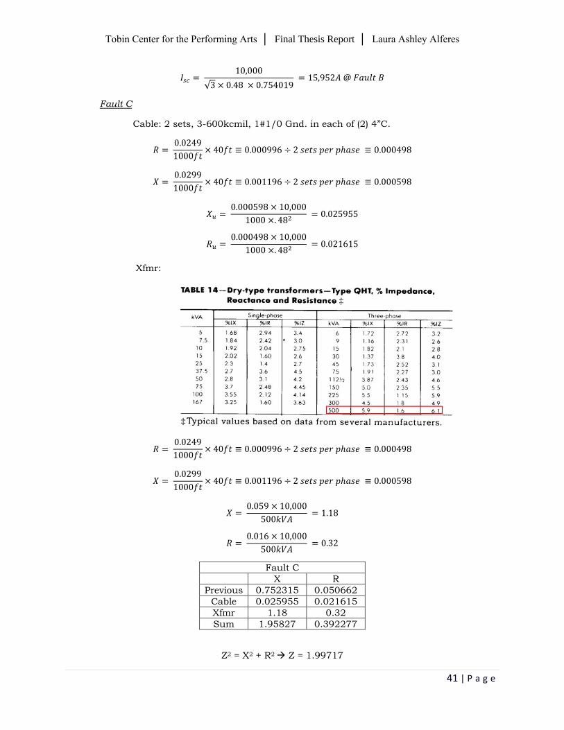
√
Fault C
Cable: 2 sets, 3-600kcmil, 1#1/0 Gnd. in each of (2) 4”C.
Xfmr:
Fault C
X R
Previous 0.752315 0.050662
Cable 0.025955 0.021615
Xfmr 1.18 0.32
Sum 1.95827 0.392277
Z2 = X2 + R2 Z = 1.99717
Tobin Center for the Performing Arts │ Final Thesis Report │ Laura Ashley Alferes
42 | P a g e
√
Fault D
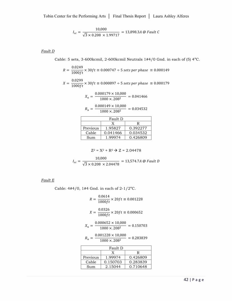
Cable: 5 sets, 3-600kcmil, 2-600kcmil Neutrals 1#4/0 Gnd. in each of (5) 4”C.
Fault D
X R
Previous 1.95827 0.392277
Cable 0.041466 0.034532
Sum 1.99974 0.426809
Z2 = X2 + R2 Z = 2.04478
√
Fault E
Cable: 4#4/0, 1#4 Gnd. in each of 2-1/2”C.
Fault D
X R
Previous 1.99974 0.426809
Cable 0.150703 0.283839
Sum 2.15044 0.710648
Tobin Center for the Performing Arts │ Final Thesis Report │ Laura Ashley Alferes
43 | P a g e
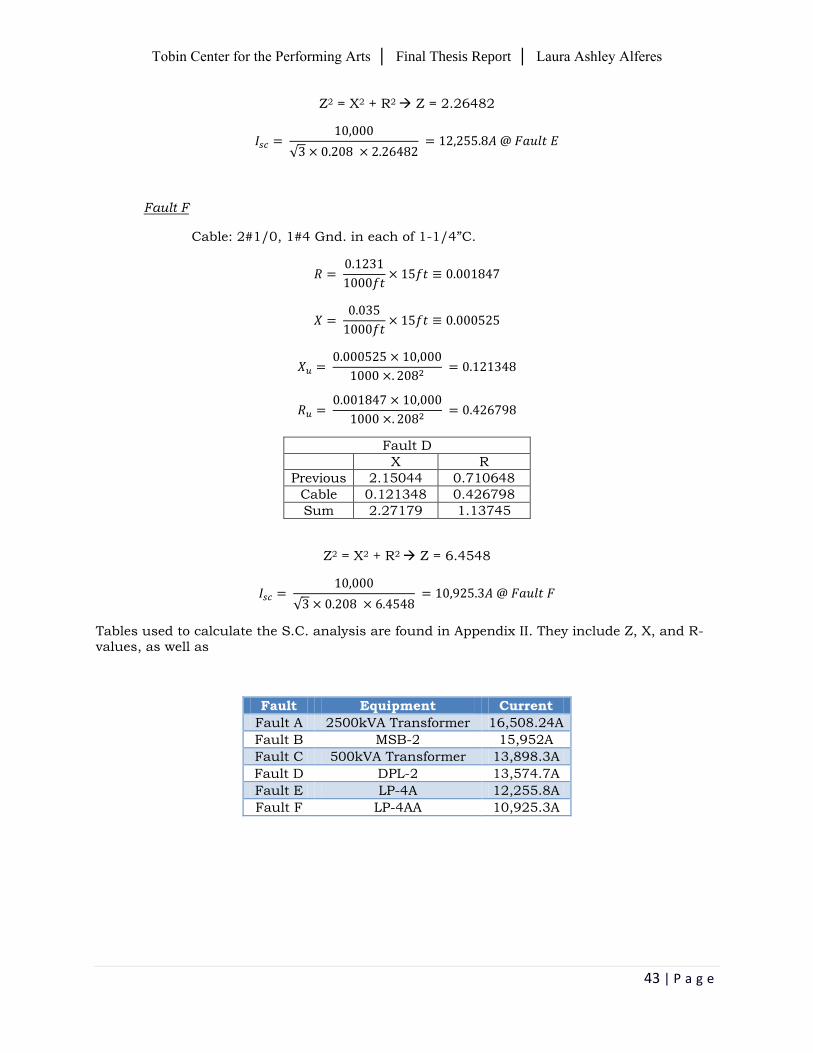
Z2 = X2 + R2 Z = 2.26482
√
Fault F
Cable: 2#1/0, 1#4 Gnd. in each of 1-1/4”C.
Fault D
X R
Previous 2.15044 0.710648
Cable 0.121348 0.426798
Sum 2.27179 1.13745
Z2 = X2 + R2 Z = 6.4548
√
Tables used to calculate the S.C. analysis are found in Appendix II. They include Z, X, and R-values, as well as
Fault Equipment Current
Fault A 2500kVA Transformer 16,508.24A
Fault B MSB-2 15,952A
Fault C 500kVA Transformer 13,898.3A
Fault D DPL-2 13,574.7A
Fault E LP-4A 12,255.8A
Fault F LP-4AA 10,925.3A
Tobin Center for the Performing Arts │ Final Thesis Report │ Laura Ashley Alferes
44 | P a g e
BUILDING-INTEGRATED PHOTOVOLTAIC (BIPV) In the construction management breadth, a cost and schedule analysis was performed for the implementation of a BIPV system. In this electrical depth, the specific characteristics of the BIPV system will be analyzed with the use of a System Advisor Model (SAM).
SAM models performance and financial data for those involved in the renewable energy industry. It provides performance predictions and cost estimates based on installation and operating costs, as well as specific parameter input to the model. SAM is a useful tool, for it provides data for both sides of the industry, either the customer side or the utility side. The customer side involves buying and selling electricity at retail rates. On the other hand, the utility side involves selling electricity at a cost negotiated through a power purchase agreement.
Photovoltaics are a promising renewable technology, in which it produces electricity on site, directly from the sun, without being worried about energy supply or environmental harm. The next generation of solar panels, however, will not only bear little resemblance to their predecessors, but they will consist of integrating photovoltaic modules into the building envelope.
The implementation of a Building Integrated Photovoltaic (BIPV) system has been studied. It can become an integral part of the Tobin Center, in which solar modules are integrated into the façade of the new addition, known as the ‘veil.’ Instead of placing a photovoltaic array near the building site, a BIPV system will add architectural interest to the building.
CPS Energy is a utility company that supplies electricity to the Tobin Center. The following website provides detailed information about solar power and solar savings, specifically for San Antonio: http://www.cpsenergysavers.com/commercial/start-saving/solar-rebates
Preliminary Understanding & Research
Central goal of solar energy design: maximize solar utility for a client or stakeholders in a given locale.
How does sunlight become solar power?
PV solar panels convert sunlight into electricity.
Typically installed where there is a maximum exposure to the sun.
Effective any time when the sun is shining.
When sunlight is intense and it strikes a PV module directly, more electricity is
produced.
Solar heat and light is absorbed by PV modules and is converted into direct
current (DC) electricity.
An inverter converts DC power into alternating current (AC) electricity. This current may be stored or used immediately.
Tobin Center for the Performing Arts │ Final Thesis Report │ Laura Ashley Alferes
45 | P a g e
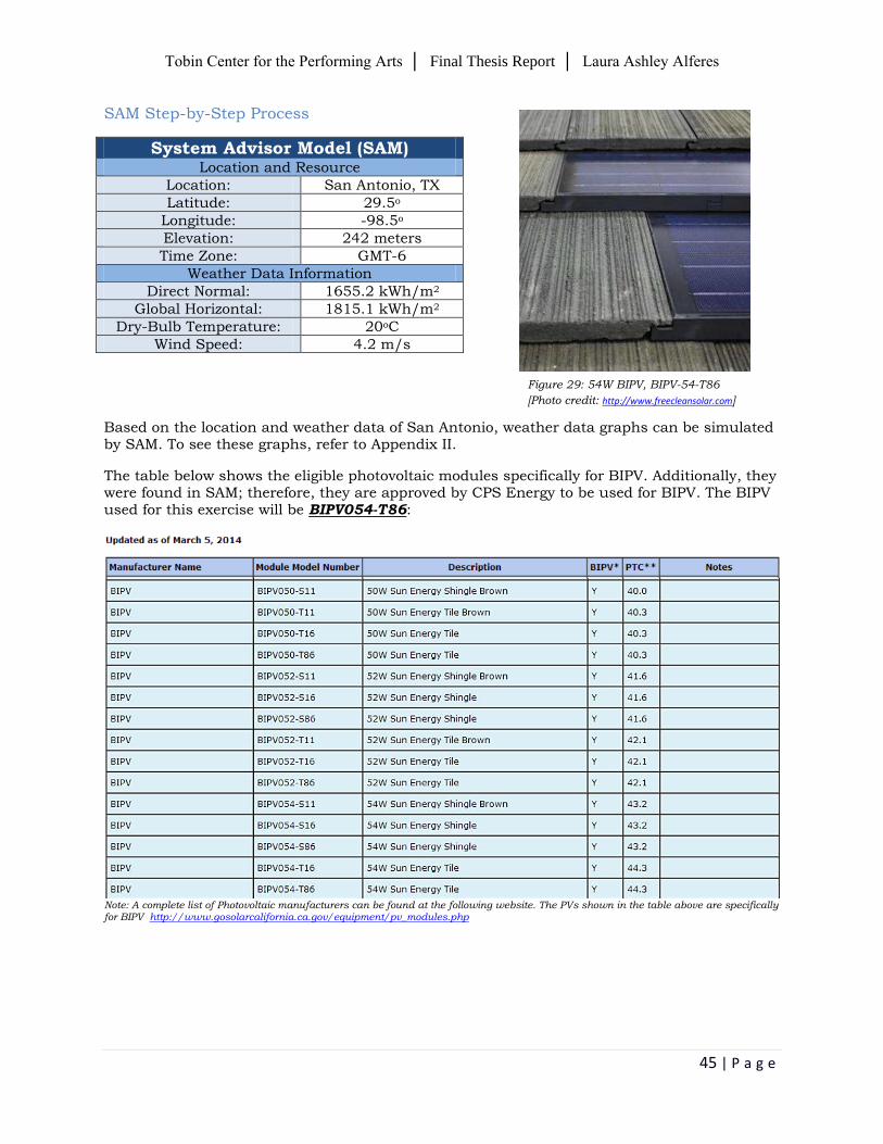
SAM Step-by-Step Process
System Advisor Model (SAM) Location and Resource
Location: San Antonio, TX
Latitude: 29.5o
Longitude: -98.5o
Elevation: 242 meters
Time Zone: GMT-6
Weather Data Information
Direct Normal: 1655.2 kWh/m2
Global Horizontal: 1815.1 kWh/m2
Dry-Bulb Temperature: 20oC
Wind Speed: 4.2 m/s
Based on the location and weather data of San Antonio, weather data graphs can be simulated by SAM. To see these graphs, refer to Appendix II.
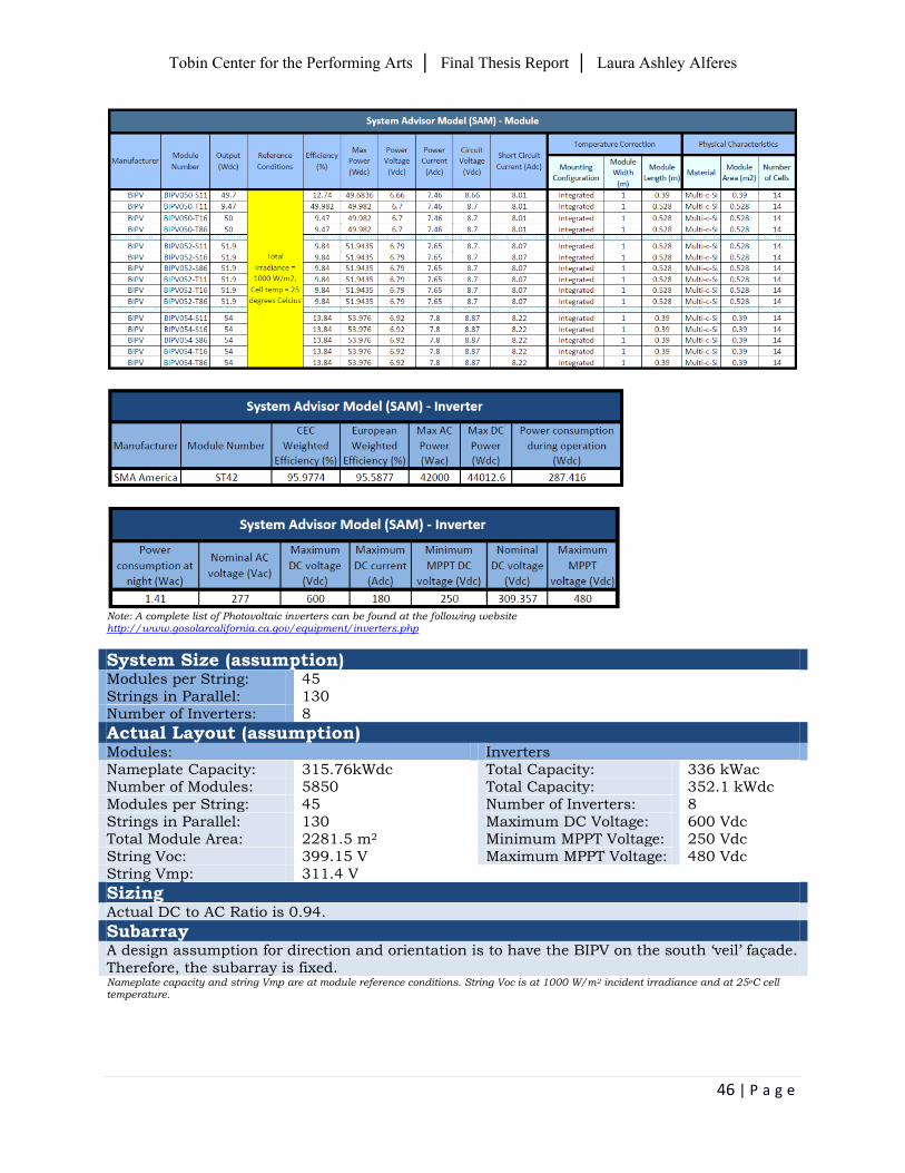
The table below shows the eligible photovoltaic modules specifically for BIPV. Additionally, they were found in SAM; therefore, they are approved by CPS Energy to be used for BIPV. The BIPV used for this exercise will be BIPV054-T86:
Note: A complete list of Photovoltaic manufacturers can be found at the following website. The PVs shown in the table above are specifically for BIPV http://www.gosolarcalifornia.ca.gov/equipment/pv_modules.php
Figure 29: 54W BIPV, BIPV-54-T86
[Photo credit: http://www.freecleansolar.com]
Tobin Center for the Performing Arts │ Final Thesis Report │ Laura Ashley Alferes
46 | P a g e
Note: A complete list of Photovoltaic inverters can be found at the following website http://www.gosolarcalifornia.ca.gov/equipment/inverters.php
System Size (assumption) Modules per String: 45 Strings in Parallel: 130 Number of Inverters: 8
Actual Layout (assumption) Modules: Inverters Nameplate Capacity: 315.76kWdc Total Capacity: 336 kWac Number of Modules: 5850 Total Capacity: 352.1 kWdc Modules per String: 45 Number of Inverters: 8 Strings in Parallel: 130 Maximum DC Voltage: 600 Vdc Total Module Area: 2281.5 m2 Minimum MPPT Voltage: 250 Vdc String Voc: 399.15 V Maximum MPPT Voltage: 480 Vdc String Vmp: 311.4 V
Sizing
Actual DC to AC Ratio is 0.94.
Subarray
A design assumption for direction and orientation is to have the BIPV on the south ‘veil’ façade. Therefore, the subarray is fixed. Nameplate capacity and string Vmp are at module reference conditions. String Voc is at 1000 W/m2 incident irradiance and at 25oC cell temperature.
Tobin Center for the Performing Arts │ Final Thesis Report │ Laura Ashley Alferes
47 | P a g e
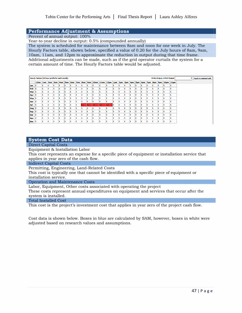
Performance Adjustment & Assumptions Percent of annual output: 100% Year-to-year decline in output: 0.5% (compounded annually) The system is scheduled for maintenance between 8am and noon for one week in July. The Hourly Factors table, shown below, specified a value of 0.20 for the July hours of 8am, 9am, 10am, 11am, and 12pm to approximate the reduction in output during that time frame. Additional adjustments can be made, such as if the grid operator curtails the system for a certain amount of time. The Hourly Factors table would be adjusted.
System Cost Data
Direct Capital Costs Equipment & Installation Labor This cost represents an expense for a specific piece of equipment or installation service that applies in year zero of the cash flow. Indirect Capital Costs Permitting, Engineering, Land-Related Costs This cost is typically one that cannot be identified with a specific piece of equipment or installation service. Operation and Maintenance Costs Labor, Equipment, Other costs associated with operating the project These costs represent annual expenditures on equipment and services that occur after the system is installed. Total Installed Cost This cost is the project’s investment cost that applies in year zero of the project cash flow.
Cost data is shown below. Boxes in blue are calculated by SAM, however, boxes in white were adjusted based on research values and assumptions.
Tobin Center for the Performing Arts │ Final Thesis Report │ Laura Ashley Alferes
48 | P a g e
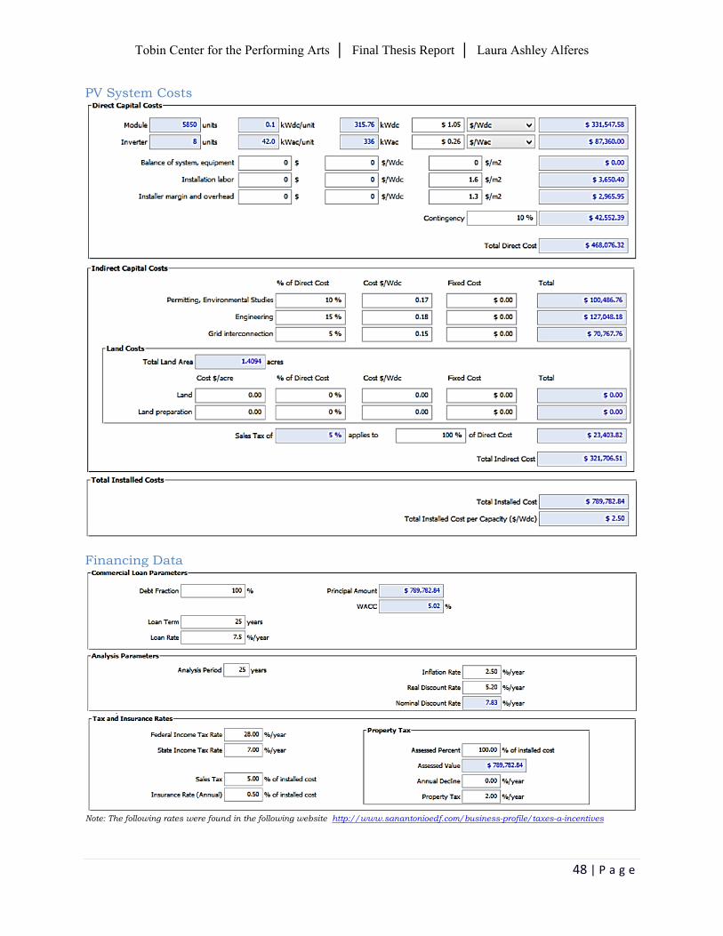
PV System Costs
Financing Data
Note: The following rates were found in the following website http://www.sanantonioedf.com/business-profile/taxes-a-incentives
Tobin Center for the Performing Arts │ Final Thesis Report │ Laura Ashley Alferes
49 | P a g e
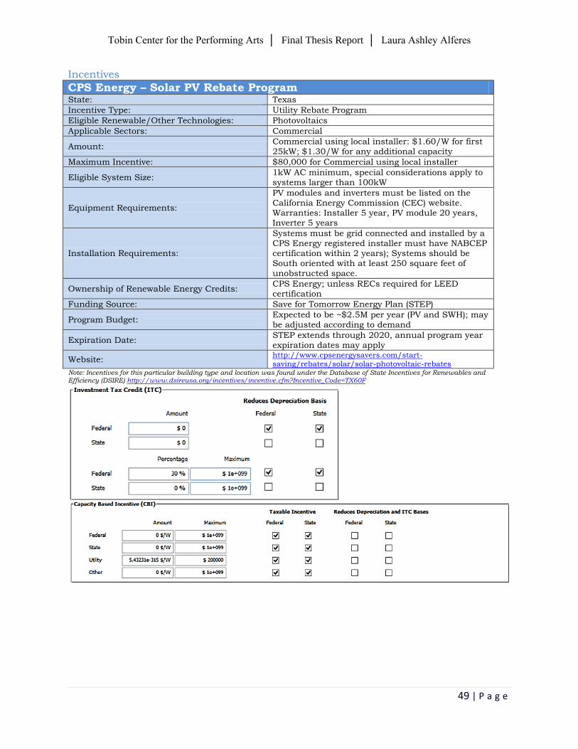
Incentives
CPS Energy – Solar PV Rebate Program State: Texas
Incentive Type: Utility Rebate Program
Eligible Renewable/Other Technologies: Photovoltaics
Applicable Sectors: Commercial
Amount: Commercial using local installer: $1.60/W for first 25kW; $1.30/W for any additional capacity
Maximum Incentive: $80,000 for Commercial using local installer
Eligible System Size: 1kW AC minimum, special considerations apply to systems larger than 100kW
Equipment Requirements:
PV modules and inverters must be listed on the California Energy Commission (CEC) website. Warranties: Installer 5 year, PV module 20 years, Inverter 5 years
Installation Requirements:
Systems must be grid connected and installed by a CPS Energy registered installer must have NABCEP certification within 2 years); Systems should be South oriented with at least 250 square feet of
unobstructed space.
Ownership of Renewable Energy Credits: CPS Energy; unless RECs required for LEED certification
Funding Source: Save for Tomorrow Energy Plan (STEP)
Program Budget: Expected to be ~$2.5M per year (PV and SWH); may be adjusted according to demand
Expiration Date: STEP extends through 2020, annual program year expiration dates may apply
Website: http://www.cpsenergysavers.com/start-saving/rebates/solar/solar-photovoltaic-rebates
Note: Incentives for this particular building type and location was found under the Database of State Incentives for Renewables and Efficiency (DSIRE) http://www.dsireusa.org/incentives/incentive.cfm?Incentive_Code=TX60F
Tobin Center for the Performing Arts │ Final Thesis Report │ Laura Ashley Alferes
50 | P a g e
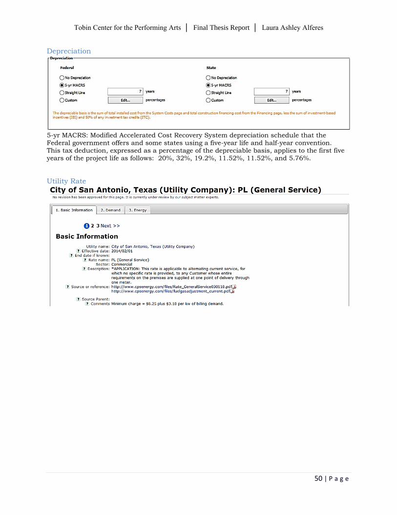
Depreciation
5-yr MACRS: Modified Accelerated Cost Recovery System depreciation schedule that the Federal government offers and some states using a five-year life and half-year convention. This tax deduction, expressed as a percentage of the depreciable basis, applies to the first five years of the project life as follows: 20%, 32%, 19.2%, 11.52%, 11.52%, and 5.76%.
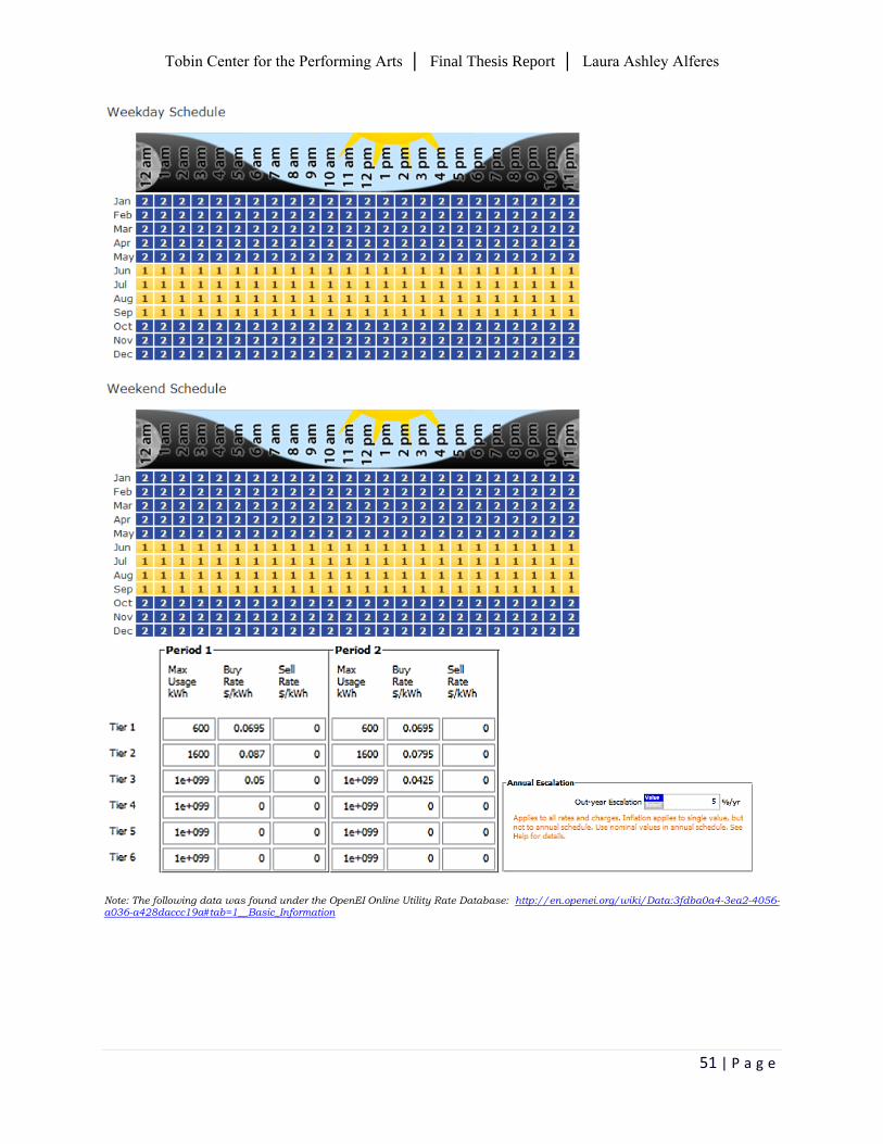
Utility Rate
Tobin Center for the Performing Arts │ Final Thesis Report │ Laura Ashley Alferes
51 | P a g e
Note: The following data was found under the OpenEI Online Utility Rate Database: http://en.openei.org/wiki/Data:3fdba0a4-3ea2-4056-a036-a428daccc19a#tab=1__Basic_Information
Tobin Center for the Performing Arts │ Final Thesis Report │ Laura Ashley Alferes
52 | P a g e
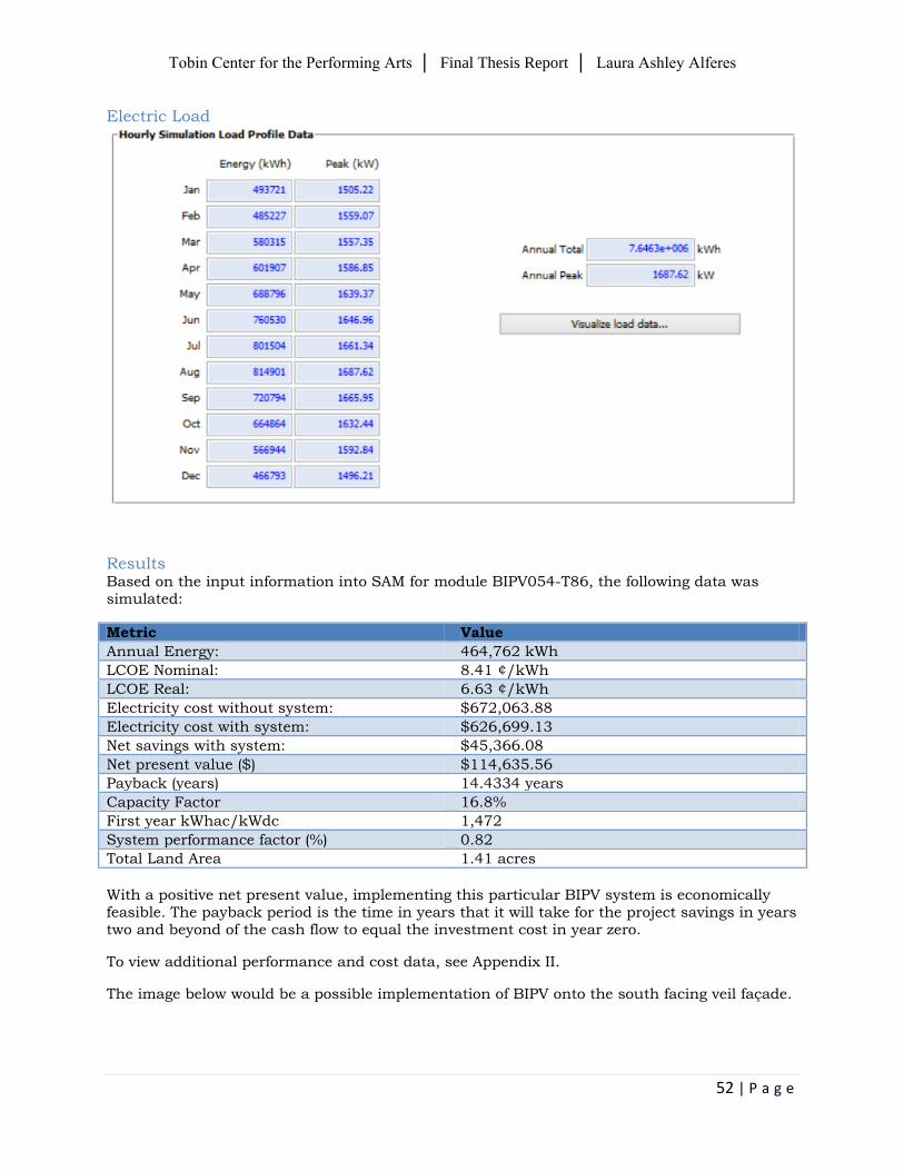
Electric Load
Results
Based on the input information into SAM for module BIPV054-T86, the following data was simulated:
Metric Value
Annual Energy: 464,762 kWh
LCOE Nominal: 8.41 ¢/kWh
LCOE Real: 6.63 ¢/kWh
Electricity cost without system: $672,063.88
Electricity cost with system: $626,699.13
Net savings with system: $45,366.08
Net present value ($) $114,635.56
Payback (years) 14.4334 years
Capacity Factor 16.8%
First year kWhac/kWdc 1,472
System performance factor (%) 0.82
Total Land Area 1.41 acres
With a positive net present value, implementing this particular BIPV system is economically feasible. The payback period is the time in years that it will take for the project savings in years two and beyond of the cash flow to equal the investment cost in year zero.
To view additional performance and cost data, see Appendix II.
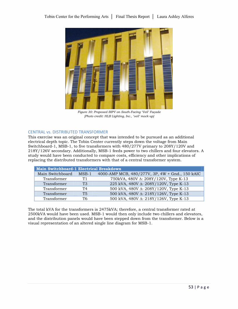
The image below would be a possible implementation of BIPV onto the south facing veil façade.
Tobin Center for the Performing Arts │ Final Thesis Report │ Laura Ashley Alferes
53 | P a g e
Figure 30: Proposed BIPV on South-Facing ‘Veil’ Façade
[Photo credit: HLB Lighting, Inc., ‘veil’ mock-up]
CENTRAL vs. DISTRIBUTED TRANSFORMER This exercise was an original concept that was intended to be pursued as an additional electrical depth topic. The Tobin Center currently steps down the voltage from Main Switchboard-1, MSB-1, to five transformers with 480/277V primary to 208Y/120V and 218Y/126V secondary. Additionally, MSB-1 feeds power to two chillers and four elevators. A study would have been conducted to compare costs, efficiency and other implications of replacing the distributed transformers with that of a central transformer system.
Main Switchboard-1 Electrical Breakdown
Main Switchboard MSB-1 4000-AMP MCB, 480/277V, 3P, 4W + Gnd., 150 kAIC
Transformer T1 750kVA, 480V ∆: 208Y/120V, Type K-13
Transformer T3 225 kVA, 480V ∆: 208Y/120V, Type K-13
Transformer T4 500 kVA, 480V ∆: 208Y/120V, Type K-13
Transformer T5 500 kVA, 480V ∆: 218Y/126V, Type K-13
Transformer T6 500 kVA, 480V ∆: 218Y/126V, Type K-13
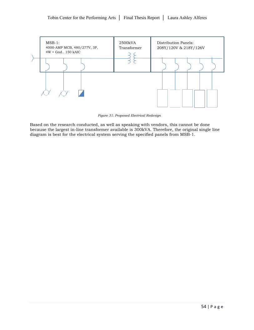
The total kVA for the transformers is 2475kVA; therefore, a central transformer rated at 2500kVA would have been used. MSB-1 would then only include two chillers and elevators, and the distribution panels would have been stepped down from the transformer. Below is a visual representation of an altered single line diagram for MSB-1.
Tobin Center for the Performing Arts │ Final Thesis Report │ Laura Ashley Alferes
54 | P a g e
Figure 31: Proposed Electrical Redesign
Based on the research conducted, as well as speaking with vendors, this cannot be done because the largest in-line transformer available is 300kVA. Therefore, the original single line diagram is best for the electrical system serving the specified panels from MSB-1.
Distribution Panels:
208Y/120V & 218Y/126V
MSB-1:
4000-AMP MCB, 480/277V, 3P,
4W + Gnd., 150 kAIC
2500kVA
Transformer
Tobin Center for the Performing Arts │ Final Thesis Report │ Laura Ashley Alferes
55 | P a g e
Section Five ǀ construction management breadth
Contributing to a possible implementation of a Building-Integrated Photovoltaic system, an in-
depth cost and schedule study was performed. Assembly estimates and supplier/vendor quotes
was provided for insight on projected initial costs and offsets, as well as the amount of building
materials and labor necessary. Additionally, comparative studies of how this system can impact
construction time and cost was researched.
The construction management breadth was completed in conjunction with the electrical depth
under the Building-Integrated Photovoltaic system. Please refer to that section for further system
detail and information.
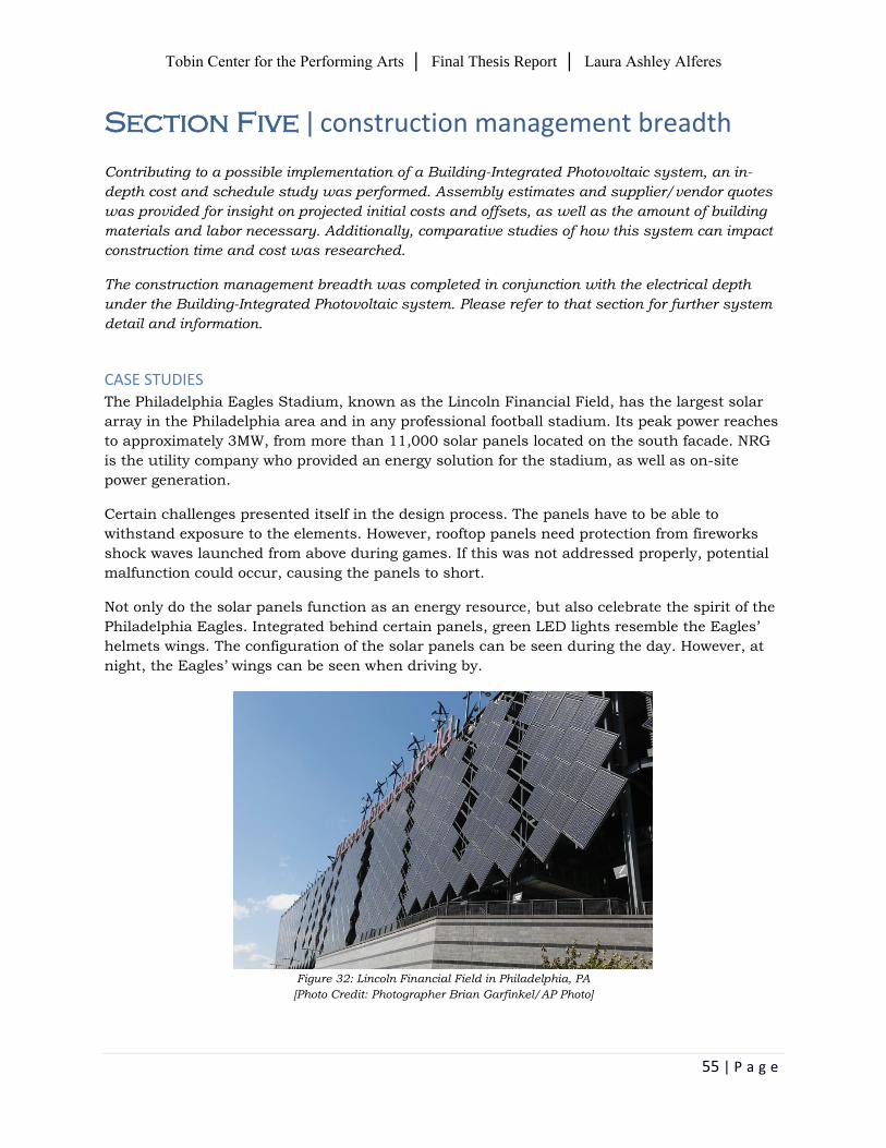
CASE STUDIES The Philadelphia Eagles Stadium, known as the Lincoln Financial Field, has the largest solar
array in the Philadelphia area and in any professional football stadium. Its peak power reaches
to approximately 3MW, from more than 11,000 solar panels located on the south facade. NRG
is the utility company who provided an energy solution for the stadium, as well as on-site
power generation.
Certain challenges presented itself in the design process. The panels have to be able to
withstand exposure to the elements. However, rooftop panels need protection from fireworks
shock waves launched from above during games. If this was not addressed properly, potential
malfunction could occur, causing the panels to short.
Not only do the solar panels function as an energy resource, but also celebrate the spirit of the
Philadelphia Eagles. Integrated behind certain panels, green LED lights resemble the Eagles’
helmets wings. The configuration of the solar panels can be seen during the day. However, at
night, the Eagles’ wings can be seen when driving by.
Figure 32: Lincoln Financial Field in Philadelphia, PA
[Photo Credit: Photographer Brian Garfinkel/AP Photo]
Tobin Center for the Performing Arts │ Final Thesis Report │ Laura Ashley Alferes
56 | P a g e
COST ANALYSIS Get-A-Quote.net is an online source that was used to obtain costs for the BIPV system.
Contractors can use this site to help with construction estimating. The 2013 Cost Estimating
Guide cost book was used to obtain assembly estimates and supplier/vendor quotes.
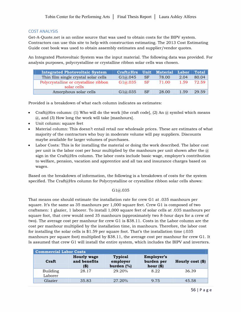
An Integrated Photovoltaic System was the input material. The following data was provided. For
analysis purposes, polycrystalline or crystalline ribbon solar cells was chosen.
Integrated Photovoltaic System Craft@Hrs Unit Material Labor Total
Thin film single crystal solar cells [email protected] SF 78.00 2.04 80.04
Polycrystalline or crystalline ribbon solar cells
[email protected] SF 71.00 1.59 72.59
Amorphous solar cells [email protected] SF 28.00 1.59 29.59
Provided is a breakdown of what each column indicates as estimates:
Craft@Hrs column: (1) Who will do the work [the craft code], (2) An @ symbol which means
@, and (3) How long the work will take [manhours].
Unit column: square feet
Material column: This doesn’t entail retail nor wholesale prices. These are estimates of what
majority of the contractors who buy in moderate volume will pay suppliers. Discounts
maybe available for larger volumes of purchases.
Labor Costs: This is for installing the material or doing the work described. The labor cost
per unit is the labor cost per hour multiplied by the manhours per unit shown after the @
sign in the Craft@Hrs column. The labor costs include basic wage, employer’s contribution
to welfare, pension, vacation and apprentice and all tax and insurance charges based on
wages.
Based on the breakdown of information, the following is a breakdown of costs for the system
specified. The Craft@Hrs column for Polycrystalline or crystalline ribbon solar cells shows:
That means one should estimate the installation rate for crew G1 at .035 manhours per
square. It’s the same as 35 manhours per 1,000 square feet. Crew G1 is composed of two
craftsmen: 1 glazier, 1 laborer. To install 1,000 square feet of solar cells at .035 manhours per
square foot, that crew would need 35 manhours (approximately two 8-hour days for a crew of
two). The average cost per manhour for crew G1 is $38.11. Costs in the Labor column are the
cost per manhour multiplied by the installation time, in manhours. Therefore, the labor cost
for installing the solar cells is $1.59 per square foot. That’s the installation time (.035
manhours per square foot) multiplied by $38.11, the average cost per manhour for crew G1. It
Is assumed that crew G1 will install the entire system, which includes the BIPV and inverters.
Commercial Labor Costs
Craft Hourly wage and benefits
($)
Typical employer
burden (%)
Employer’s burden per
hour ($) Hourly cost ($)
Building Laborer
28.17 29.20% 8.22 36.39
Glazier 35.83 27.20% 9.75 45.58
Tobin Center for the Performing Arts │ Final Thesis Report │ Laura Ashley Alferes
57 | P a g e
SCHEDULE ANALYSIS
A construction schedule, dated February 1, 2012, was provided for the purpose and use of this
thesis. Recent and updated schedules, however, were not provided. The original schedule
concluded with major construction equipment, including tower crane(s), erect crane(s), and
operates crane(s). Refer to Appendix III for the original construction schedule.
The following assumptions have been made:
‘Veil’ façade erection (~7 wks)
BIPV installation on the ‘veil’ (~3 wks)
Based on this assumption and from the original schedule provided, the critical path will not be
affected in a negative way. With the proper crew and their allotted manhours, construction
time, including the BIPV installation, should still be on schedule for completion in July 2014.
CONCLUSION
Based on this assumption and from the original schedule provided, the critical path will not be
affected in a negative way. With the proper crew and their allotted manhours, construction
time, including the BIPV installation, should still be on schedule for completion in July 2014.
Tobin Center for the Performing Arts │ Final Thesis Report │ Laura Ashley Alferes
58 | P a g e
Section Six ǀ mechanical breadth
The mechanical breadth includes utilizing biogas as a renewable energy source for onsite use.
Thorough research was done to understand how such greenhouse gases can be transformed into
a power source and used as energy for electricity and heat generation. Further studies focus on
system implementation and interaction with the HVAC and power distribution systems.
ENVIRONMENTAL TRIFECTA Texas is typically associated with oil, but with its ongoing armloads of green jobs, solar energy
is highly embraced. Located in Bexar County, TX, the San Antonio Water System (SAWS)
partnered with a national energy company, Ameresco, Inc., to process and treat wastewater for
positive environmental outcomes. This partnership established the first sustainable project of
its kind in the nation at a biogas facility at the Dos Rios Water Recycling Center.
Wastewater is commonly disposed of quickly. However, SAWS Dos Rios turns wastewater into
valuable resources, which they like to call the “environmental trifecta.”
SAWS Dos Rios “Environmental Trifecta”:
Recycled water: irrigation an industrial processes
Compost: biosolids to compost production and soil conditioning
Biogas: captured gas to be used for heat and power production
BIOGAS Biogas is a byproduct of several agricultural, food processing and industrial processes. It is
used today as a fuel source for engine generators. Biogas is produced through anaerobic
decomposition or organic waste, which consists primarily of methane and carbon dioxide.
Biodegradable materials, such as manure, sewage, municipal waste, plant material, etc., are
fermented through this process. However, several other gases from organic waste-industries to
animal or domestic origin waste, etc., contribute to its chemical composition and physical
characteristics.
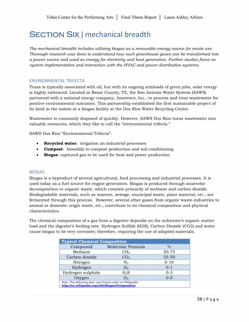
The chemical composition of a gas from a digester depends on the substrate’s organic matter
load and the digester’s feeding rate. Hydrogen Sulfide (H2S), Carbon Dioxide (CO2) and water
cause biogas to be very corrosive; therefore, requiring the use of adapted materials.
Typical Chemical Composition
Compound Molecular Formula %
Methane CH4 50-75
Carbon dioxide CO2 25-50
Nitrogen N2 0-10
Hydrogen H2 0-1
Hydrogen sulphide H2S 0-3
Oxygen O2 0-0 Note: The following data was found under on Wikipedia http://en.wikipedia.org/wiki/Biogas#Composition
Tobin Center for the Performing Arts │ Final Thesis Report │ Laura Ashley Alferes
59 | P a g e
METHOD Two primary methods of recovering biogas for use as energy:
1. Create an anaerobic digestion system to process waste, typically manure or other wet
biomass.
2. Recover natural biogas production that is formed in existing landfills. This can then be
converted into energy is several methods.
Anaerobic digestion is made up of several components:
Manure collection system
Anaerobic digester
Biogas handling system
Gas use device
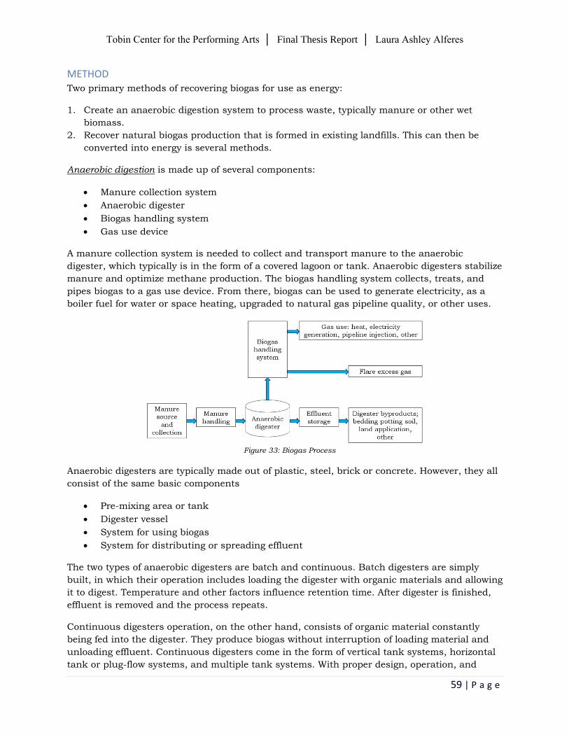
A manure collection system is needed to collect and transport manure to the anaerobic
digester, which typically is in the form of a covered lagoon or tank. Anaerobic digesters stabilize
manure and optimize methane production. The biogas handling system collects, treats, and
pipes biogas to a gas use device. From there, biogas can be used to generate electricity, as a
boiler fuel for water or space heating, upgraded to natural gas pipeline quality, or other uses.
Figure 33: Biogas Process
Anaerobic digesters are typically made out of plastic, steel, brick or concrete. However, they all
consist of the same basic components
Pre-mixing area or tank
Digester vessel
System for using biogas
System for distributing or spreading effluent
The two types of anaerobic digesters are batch and continuous. Batch digesters are simply
built, in which their operation includes loading the digester with organic materials and allowing
it to digest. Temperature and other factors influence retention time. After digester is finished,
effluent is removed and the process repeats.
Continuous digesters operation, on the other hand, consists of organic material constantly
being fed into the digester. They produce biogas without interruption of loading material and
unloading effluent. Continuous digesters come in the form of vertical tank systems, horizontal
tank or plug-flow systems, and multiple tank systems. With proper design, operation, and
Tobin Center for the Performing Arts │ Final Thesis Report │ Laura Ashley Alferes
60 | P a g e
maintenance of continuous digesters, a steady supply of useable biogas is produced, which is
better for large-scale operations.
Landfill gas collection system is made up of several components:
Landfill gas well
Landfill gas wellhead
Landfill gas processing and treatment
Landfill gas flare
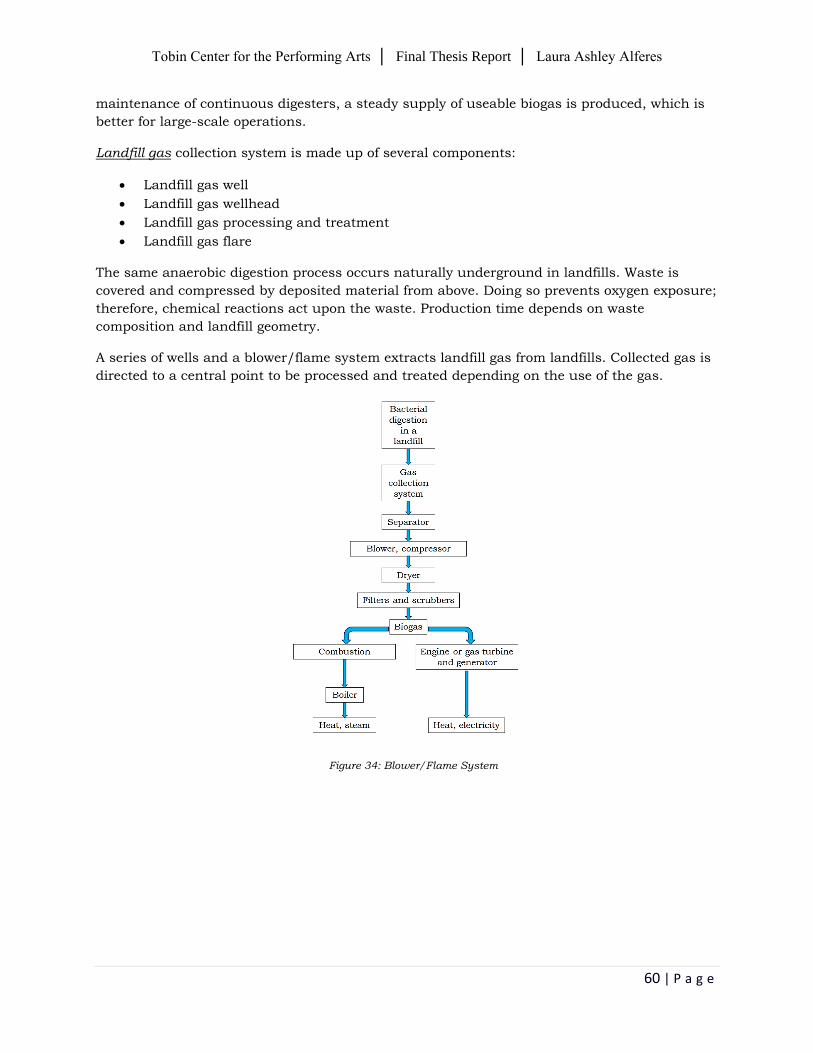
The same anaerobic digestion process occurs naturally underground in landfills. Waste is
covered and compressed by deposited material from above. Doing so prevents oxygen exposure;
therefore, chemical reactions act upon the waste. Production time depends on waste
composition and landfill geometry.
A series of wells and a blower/flame system extracts landfill gas from landfills. Collected gas is
directed to a central point to be processed and treated depending on the use of the gas.
Figure 34: Blower/Flame System
Tobin Center for the Performing Arts │ Final Thesis Report │ Laura Ashley Alferes
61 | P a g e
PROCESS
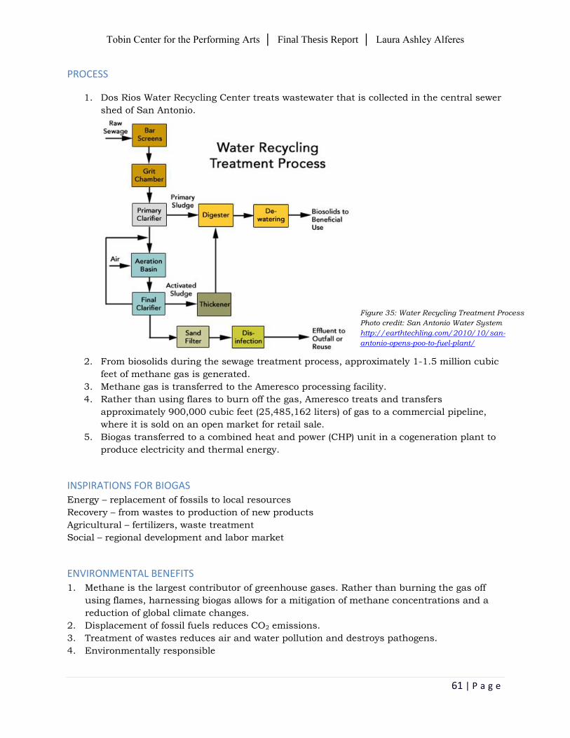
1. Dos Rios Water Recycling Center treats wastewater that is collected in the central sewer
shed of San Antonio.
2. From biosolids during the sewage treatment process, approximately 1-1.5 million cubic
feet of methane gas is generated.
3. Methane gas is transferred to the Ameresco processing facility.
4. Rather than using flares to burn off the gas, Ameresco treats and transfers
approximately 900,000 cubic feet (25,485,162 liters) of gas to a commercial pipeline,
where it is sold on an open market for retail sale.
5. Biogas transferred to a combined heat and power (CHP) unit in a cogeneration plant to
produce electricity and thermal energy.
INSPIRATIONS FOR BIOGAS Energy – replacement of fossils to local resources
Recovery – from wastes to production of new products
Agricultural – fertilizers, waste treatment
Social – regional development and labor market
ENVIRONMENTAL BENEFITS 1. Methane is the largest contributor of greenhouse gases. Rather than burning the gas off
using flames, harnessing biogas allows for a mitigation of methane concentrations and a
reduction of global climate changes.
2. Displacement of fossil fuels reduces CO2 emissions.
3. Treatment of wastes reduces air and water pollution and destroys pathogens.
4. Environmentally responsible
Figure 35: Water Recycling Treatment Process Photo credit: San Antonio Water System
http://earthtechling.com/2010/10/san-
antonio-opens-poo-to-fuel-plant/
Tobin Center for the Performing Arts │ Final Thesis Report │ Laura Ashley Alferes
62 | P a g e
PROPOSED SYSTEM REDESIGN Currently, the mechanical and electrical systems are highly complex. There are two main
switchboards that distribute power to all systems. Eleven air-handling units (AHU) supply and
circulate air throughout the building.
Since CPS Energy is the utility provider, they support and encourage cogeneration, where
combined heat and power (CHP) devices produce thermal and electrical energy. A proposed
system redesign would involve eliminating AHUs that serve the Tobin Center and replace with
fewer CHP units or the amount needed to carry mechanical and electrical loads.
A proposed system redesign would involve:
Completely replace or eliminate the appropriate amount of AHU
Reduce and resize main switchboards and distribution panels
Probable outcome:
Increase energy efficiency
Resize mechanical and electrical equipment
Reduce square footage of mechanical and electrical rooms
Tobin Center for the Performing Arts │ Final Thesis Report │ Laura Ashley Alferes
63 | P a g e
Summary & Conclusion
Overall, great endeavor was put forth to provide designs for engineering systems in the Tobin
Center for the Performing Arts. With embracing the arts as a core concept, the lighting creates
an engaging and welcoming environment in all spaces redesigned. Interior and exterior lighting
complements the unique architecture that makes up each space, giving rise for it to resonate in
San Antonio.
In addition, the electrical depths and breadth topics explored potential solar and energy system
integrations. Implementing a Building-Integrated Photovoltaic system cannot only help gain
solar energy and converting it to electricity, but also reduce total energy loads. Biogas can be a
form of energy for on-site use.
Although many aspects of the existing system designs were already impressive and efficient,
this thesis was successful in accomplishing the goal to consider alternative and new designs,
while meeting or possibly exceeding the same criteria.
Many aspects of the existing system designs were already impressive and efficient. However, for
the purpose of this thesis, it was successful in accomplishing the goal to consider alternative
and new designs, while meeting or possibly exceeding the same criteria, but with a different
concept.
Tobin Center for the Performing Arts │ Final Thesis Report │ Laura Ashley Alferes
64 | P a g e
References
DiLaura, David L., Kevin W. Houser, Richard G. Mistrick, and Gary R. Steffy, eds. Illumination
Engineering Society Lighting Handbook 10th Edition Reference and Application.
"Light in Architecture and Psychology of Light, RS Lighting Design."
Lecture. Http://www.rsltg.com/images/ArchID_-
_Light_in_Architecture_and_Psychology_of_Light.pdf. Web.
Product, #. 86269. Ashrae 90.1-2010 Energy Standard for Buildings except Low-rise Residential
Buildings. [S.l.]: Ashrae, n.d. Print.
"COMcheck." Building Energy Codes Program. N.p., n.d. Web. 14 Mar. 2014.
<https://www.energycodes.gov/comcheck>.
Earley, Mark W., and Jeffrey S. Sargent. National Electrical Code. 2011 ed. Quincy, MA:
National Fire Protection Association, 2010. Print.
GE. "Short-Circuit Current Calculations for Industrial and Commercial Power Systems." GE
Industrial. GE, n.d. Web. 10 Feb. 2014.
<http://apps.geindustrial.com/publibrary/checkout/GET-
3550F?TNR=White%20Papers|GET-3550F|generic>.
"Get A Quote On Nearly Any Construction Material." Get A Quote On Nearly Any Construction
Material. N.p., n.d. Web. 10 Mar. 2014. <http://www.get-a-quote.net/>.
NRG Energy, Inc., ed. Solar Power Installation at Lincoln Financial Field. Publication. NRG
Energy, Inc., n.d. Web. 10 Mar. 2014. <http://www.nrgsolar.com/wp-
content/uploads/2013/07/lincolnNRG-1671-Lincoln-Football-Stadium-Fact-Sheets-v8-
EMAIL.pdf>.
"San Antonio Opens Poo-To-Fuel Plant." EarthTechling. N.p., n.d. Web. 16 Mar. 2014.
<http://earthtechling.com/2010/10/san-antonio-opens-poo-to-fuel-plant/>.
"San Antonio Water System." San Antonio Water System. N.p., n.d. Web. 15 Mar. 2014.
<http://www.saws.org/>.
"Solar PV." Commercial Solar Rebates. N.p., n.d. Web. 15 Mar. 2014.
<http://www.cpsenergysavers.com/commercial/start-saving/solar-rebates>.
"Taxes & Incentives." Taxes & Incentives. N.p., n.d. Web. 17 Mar. 2014.
<http://www.sanantonioedf.com/business-profile/taxes-a-incentives>.
Tobin Center for the Performing Arts │ Final Thesis Report │ Laura Ashley Alferes
65 | P a g e
Acknowledgements
Thank you to the many individuals who made this thesis possible.
Matthew Snellgrove Project Director, The Projects Group Clifton Manahan Lighting Designer, HLB Lighting Design, Inc. Dr. Kevin Houser Thesis Advisor, AE Lighting Professor, Penn State Leslie Beahm Electrical Advisor, Reese Engineering Dr. Richard Mistrick AE Lighting Associate Professor, Penn State Dr. Jeffrey Brownson
Assistant Professor, Department of Energy % Mineral Engineering, Penn State
Family and friends for their continuous support.