Embed Size (px)
Citation preview

1
Lecture 10
Today’s objectives:— Intro to Pipelining

2
A relevant question
Assuming you’ve got:— One washer (takes 30 minutes)
— One drier (takes 40 minutes)
— One “folder” (takes 20 minutes)
It takes 90 minutes to wash, dry, and fold 1 load of laundry.— How long does 4 loads take?

3
The slow way
If each load is done sequentially it takes 6 hours
30 40 20 30 40 20 30 40 20 30 40 20
6 PM 7 8 9 10 11 Midnight
Time

4
Laundry Pipelining
Start each load as soon as possible— Overlap loads
Pipelined laundry takes 3.5 hours
6 PM 7 8 9 10 11 Midnight
Time
30 40 40 40 40 20
5
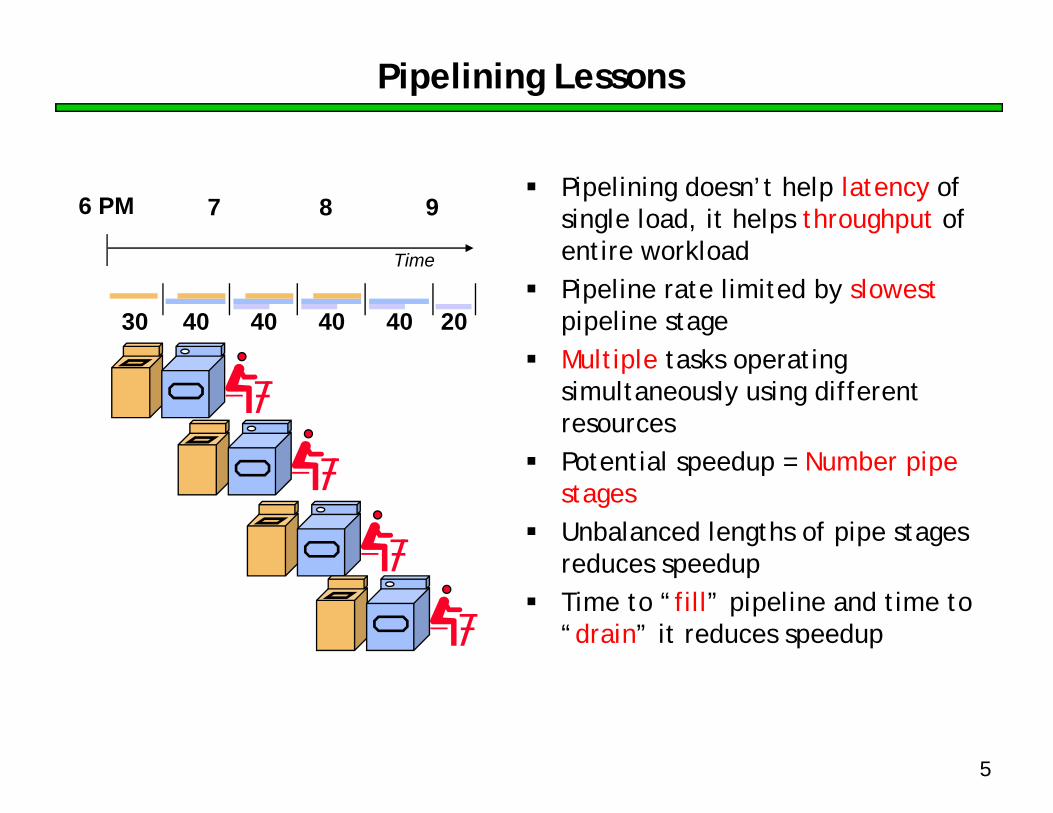
Pipelining Lessons
Pipelining doesn’t help latency of single load, it helps throughput of entire workloadPipeline rate limited by slowestpipeline stageMultiple tasks operating simultaneously using different resourcesPotential speedup = Number pipe stagesUnbalanced lengths of pipe stages reduces speedupTime to “fill” pipeline and time to “drain” it reduces speedup
6 PM 7 8 9
Time
30 40 40 40 40 20

6
Pipelining
Pipelining is a general-purpose efficiency technique— It is not specific to processors
Pipelining is used in:— Assembly lines— Bucket brigades— Fast food restaurants
Pipelining is used in other CS disciplines:— Networking— Server software architecture
Useful to increase throughput in the presence of long latency— More on that later…

7
Instruction execution review
Executing a MIPS instruction can take up to five steps.
However, as we saw, not all instructions need all five steps.
Step Name Description
Instruction Fetch IF Read an instruction from memory.
Instruction Decode ID Read source registers and generate control signals.
Execute EX Compute an R-type result or a branch outcome.
Memory MEM Read or write the data memory.
Writeback WB Store a result in the destination register.
Instruction Steps required
beq IF ID EX
R-type IF ID EX WB
sw IF ID EX MEM
lw IF ID EX MEM WB

8
Single-cycle datapath diagram
4
Shiftleft 2
PC Add
Add
0Mux1
PCSrc
Readaddress
Writeaddress
Writedata
Datamemory
Readdata
MemWrite
MemRead
1Mux0
MemToRegReadaddress
Instructionmemory
Instruction[31-0]
I [15 - 0]
I [25 - 21]
I [20 - 16]
I [15 - 11]
0Mux1
RegDst
Readregister 1
Readregister 2
Writeregister
Writedata
Readdata 2
Readdata 1
Registers
RegWrite
Signextend
0Mux1
ALUSrc
Result
ZeroALU
ALUOp2ns
2ns2ns
1ns
How long does it take to execute each instruction?

9
Single-cycle review
All five execution steps occur in one clock cycle.This means the cycle time must be long enough to accommodate all the steps of the most complex instruction—a “lw” in our instruction set.— If the register file has a 1ns latency and the memories and ALU have a
2ns latency, “lw” will require 8ns.— Thus all instructions will take 8ns to execute.
Each hardware element can only be used once per clock cycle.— A “lw” or “sw” must access memory twice (in the IF and MEM stages),
so there are separate instruction and data memories.— There are multiple adders, since each instruction increments the PC
(IF) and performs another computation (EX). On top of that, branches also need to compute a target address.

10
Example: Instruction Fetch (IF)
Readaddress
Instructionmemory
Instruction[31-0]
Readaddress
Writeaddress
Writedata
Datamemory
Readdata
MemWrite
MemRead
1Mux0
MemToReg
Signextend
0Mux1
ALUSrc
Result
ZeroALU
ALUOp
I [15 - 0]
I [25 - 21]
I [20 - 16]
I [15 - 11]
0Mux1
RegDst
Readregister 1
Readregister 2
Writeregister
Writedata
Readdata 2
Readdata 1
Registers
RegWrite
Let’s quickly review how lw is executed in the single-cycle datapath.We’ll ignore PC incrementing and branching for now.In the Instruction Fetch (IF) step, we read the instruction memory.

11
Instruction Decode (ID)
Readaddress
Instructionmemory
Instruction[31-0]
Readaddress
Writeaddress
Writedata
Datamemory
Readdata
MemWrite
MemRead
1Mux0
MemToReg
Signextend
0Mux1
ALUSrc
Result
ZeroALU
ALUOp
I [15 - 0]
I [25 - 21]
I [20 - 16]
I [15 - 11]
0Mux1
RegDst
Readregister 1
Readregister 2
Writeregister
Writedata
Readdata 2
Readdata 1
Registers
RegWrite
The Instruction Decode (ID) step reads the source registers from the register file.

12
Execute (EX)
Readaddress
Instructionmemory
Instruction[31-0]
Readaddress
Writeaddress
Writedata
Datamemory
Readdata
MemWrite
MemRead
1Mux0
MemToReg
Signextend
0Mux1
ALUSrc
Result
ZeroALU
ALUOp
I [15 - 0]
I [25 - 21]
I [20 - 16]
I [15 - 11]
0Mux1
RegDst
Readregister 1
Readregister 2
Writeregister
Writedata
Readdata 2
Readdata 1
Registers
RegWrite
The third step, Execute (EX), computes the effective memory address from the source register and the instruction’s constant field.

13
Memory (MEM)
Readaddress
Instructionmemory
Instruction[31-0]
Readaddress
Writeaddress
Writedata
Datamemory
Readdata
MemWrite
MemRead
1Mux0
MemToReg
Signextend
0Mux1
ALUSrc
Result
ZeroALU
ALUOp
I [15 - 0]
I [25 - 21]
I [20 - 16]
I [15 - 11]
0Mux1
RegDst
Readregister 1
Readregister 2
Writeregister
Writedata
Readdata 2
Readdata 1
Registers
RegWrite
The Memory (MEM) step involves reading the data memory, from the address computed by the ALU.

14
Writeback (WB)
Readaddress
Instructionmemory
Instruction[31-0]
Readaddress
Writeaddress
Writedata
Datamemory
Readdata
MemWrite
MemRead
1Mux0
MemToReg
Signextend
0Mux1
ALUSrc
Result
ZeroALU
ALUOp
I [15 - 0]
I [25 - 21]
I [20 - 16]
I [15 - 11]
0Mux1
RegDst
Readregister 1
Readregister 2
Writeregister
Writedata
Readdata 2
Readdata 1
Registers
RegWrite
Finally, in the Writeback (WB) step, the memory value is stored into the destination register.

15
A bunch of lazy functional units
Notice that each execution step uses a different functional unit. In other words, the main units are idle for most of the 8ns cycle!— The instruction RAM is used for just 2ns at the start of the cycle.— Registers are read once in ID (1ns), and written once in WB (1ns).— The ALU is used for 2ns near the middle of the cycle.— Reading the data memory only takes 2ns as well.
That’s a lot of hardware sitting around doing nothing.

16
Putting those slackers to work
We shouldn’t have to wait for the entire instruction to complete before we can re-use the functional units.For example, the instruction memory is free in the Instruction Decode step as shown below, so...
Readaddress
Instructionmemory
Instruction[31-0]
Readaddress
Writeaddress
Writedata
Datamemory
Readdata
MemWrite
MemRead
1Mux0
MemToReg
Signextend
0Mux1
ALUSrc
Result
ZeroALU
ALUOp
I [15 - 0]
I [25 - 21]
I [20 - 16]
I [15 - 11]
0Mux1
RegDst
Readregister 1
Readregister 2
Writeregister
Writedata
Readdata 2
Readdata 1
Registers
RegWrite
Instruction Decode (ID)Idle

17
Decoding and fetching together
Why don’t we go ahead and fetch the next instruction while we’re decoding the first one?
Instructionmemory
Instruction[31-0]
Readaddress
Writeaddress
Writedata
Datamemory
Readdata
MemWrite
MemRead
1Mux0
MemToReg
Signextend
0Mux1
ALUSrc
Result
ZeroALU
ALUOp
I [15 - 0]
I [25 - 21]
I [20 - 16]
I [15 - 11]
0Mux1
RegDst
Readregister 1
Readregister 2
Writeregister
Writedata
Readdata 2
Readdata 1
Registers
RegWrite
Readaddress
Decode 1st instructionFetch 2nd

18
Executing, decoding and fetching
Similarly, once the first instruction enters its Execute stage, we can go ahead and decode the second instruction.But now the instruction memory is free again, so we can fetch the third instruction!
Readaddress
Instructionmemory
Instruction[31-0]
Readaddress
Writeaddress
Writedata
Datamemory
Readdata
MemWrite
MemRead
1Mux0
MemToReg
Signextend
0Mux1
ALUSrc
Result
ZeroALU
ALUOp
I [15 - 0]
I [25 - 21]
I [20 - 16]
I [15 - 11]
0Mux1
RegDst
Readregister 1
Readregister 2
Writeregister
Writedata
Readdata 2
Readdata 1
Registers
RegWrite
Decode 2ndFetch 3rd Execute 1st

19
Making Pipelining Work
We’ll make our pipeline 5 stages long, to handle load instructions as they were handled in the multi-cycle implementation— Stages are: IF, ID, EX, MEM, and WB
We want to support executing 5 instructions simultaneously: one in each stage.

20
Break datapath into 5 stages
Each stage has its own functional units.Each stage can execute in 2ns
Readaddress
Instructionmemory
Instruction[31-0]
Readaddress
Writeaddress
Writedata
Datamemory
Readdata
MemWrite
MemRead
1Mux0
MemToReg
Signextend
0Mux1
ALUSrc
Result
ZeroALU
ALUOp
I [15 - 0]
I [25 - 21]
I [20 - 16]
I [15 - 11]
0Mux1
RegDst
Readregister 1
Readregister 2
Writeregister
Writedata
Readdata 2
Readdata 1
Registers
RegWrite
IDIF EXE MEM WB
2ns 2ns 2ns2ns

21
Pipelining Loads
6 PM 7 8 9Time
30 40 40 40 40 20
Clock cycle1 2 3 4 5 6 7 8 9
lw $t0, 4($sp) IF ID EX MEM WB
lw $t1, 8($sp) IF ID EX MEM WB
lw $t2, 12($sp) IF ID EX MEM WB
lw $t3, 16($sp) IF ID EX MEM WB
lw $t4, 20($sp) IF ID EX MEM WB

22
A pipeline diagram
A pipeline diagram shows the execution of a series of instructions.— The instruction sequence is shown vertically, from top to bottom.— Clock cycles are shown horizontally, from left to right.— Each instruction is divided into its component stages. (We show five
stages for every instruction, which will make the control unit easier.)This clearly indicates the overlapping of instructions. For example, there are three instructions active in the third cycle above.— The “lw” instruction is in its Execute stage.— Simultaneously, the “sub” is in its Instruction Decode stage.— Also, the “and” instruction is just being fetched.
Clock cycle1 2 3 4 5 6 7 8 9
lw $t0, 4($sp) IF ID EX MEM WB
sub $v0, $a0, $a1 IF ID EX MEM WB
and $t1, $t2, $t3 IF ID EX MEM WB
or $s0, $s1, $s2 IF ID EX MEM WB
add $sp, $sp, -4 IF ID EX MEM WB

23
Pipeline terminology
The pipeline depth is the number of stages—in this case, five.In the first four cycles here, the pipeline is filling, since there are unused functional units.In cycle 5, the pipeline is full. Five instructions are being executed simultaneously, so all hardware units are in use. In cycles 6-9, the pipeline is emptying.
filling full emptying
Clock cycle1 2 3 4 5 6 7 8 9
lw $t0, 4($sp) IF ID EX MEM WB
sub $v0, $a0, $a1 IF ID EX MEM WB
and $t1, $t2, $t3 IF ID EX MEM WB
or $s0, $s1, $s2 IF ID EX MEM WB
add $sp, $sp, -4 IF ID EX MEM WB

24
Pipelining Performance
Execution time on ideal pipeline:— time to fill the pipeline + one cycle per instruction— N instructions -> 4 cycles + N cycles or (2N + 8) ns for 2ns clock period
Compare with single-cycle implementation:— N cycles or 8N ns for 8ns clock period
How much faster is pipelining for N=1000 ?
Clock cycle
1 2 3 4 5 6 7 8 9lw $t0, 4($sp) IF ID EX MEM WB
lw $t1, 8($sp) IF ID EX MEM WB
lw $t2, 12($sp) IF ID EX MEM WB
lw $t3, 16($sp) IF ID EX MEM WB
lw $t4, 20($sp) IF ID EX MEM WBfilling

25
Pipeline Datapath: Resource RequirementsClock cycle
1 2 3 4 5 6 7 8 9lw $t0, 4($sp) IF ID EX MEM WB
lw $t1, 8($sp) IF ID EX MEM WB
lw $t2, 12($sp) IF ID EX MEM WB
lw $t3, 16($sp) IF ID EX MEM WB
lw $t4, 20($sp) IF ID EX MEM WB
We need to perform several operations in the same cycle.— Increment the PC and add registers at the same time. — Fetch one instruction while another one reads or writes data.
Thus, like the single-cycle datapath, a pipelined processor duplicates hardware elements that are needed several times in the same clock cycle.
26
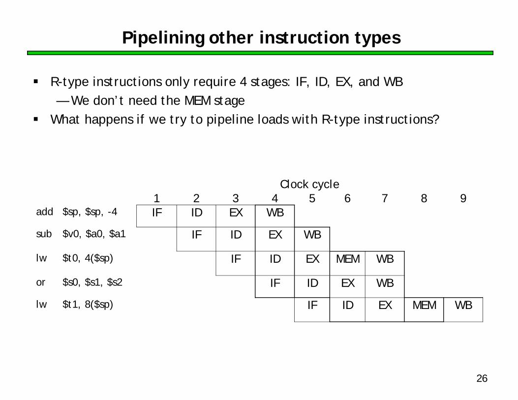
Pipelining other instruction types
R-type instructions only require 4 stages: IF, ID, EX, and WB— We don’t need the MEM stage
What happens if we try to pipeline loads with R-type instructions?
Clock cycle1 2 3 4 5 6 7 8 9
add $sp, $sp, -4 IF ID EX WB
sub $v0, $a0, $a1 IF ID EX WB
lw $t0, 4($sp) IF ID EX MEM WB
or $s0, $s1, $s2 IF ID EX WB
lw $t1, 8($sp) IF ID EX MEM WB
27
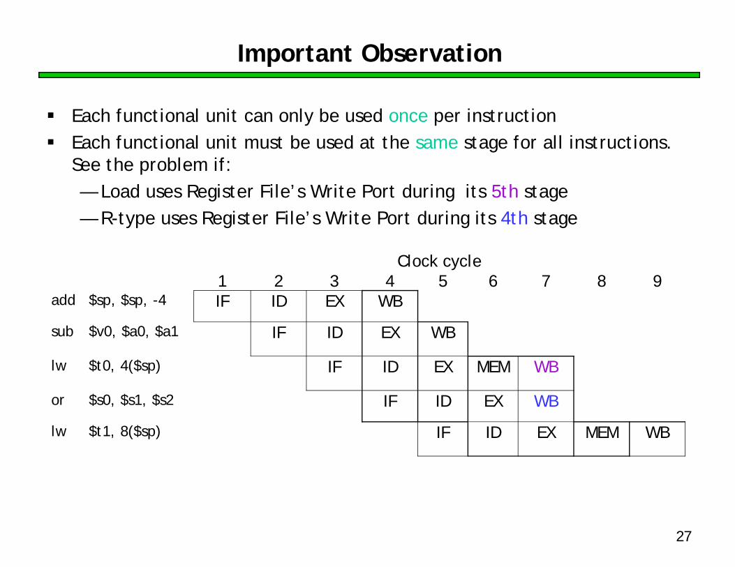
Important Observation
Each functional unit can only be used once per instructionEach functional unit must be used at the same stage for all instructions. See the problem if:— Load uses Register File’s Write Port during its 5th stage— R-type uses Register File’s Write Port during its 4th stage
Clock cycle1 2 3 4 5 6 7 8 9
add $sp, $sp, -4 IF ID EX WB
sub $v0, $a0, $a1 IF ID EX WB
lw $t0, 4($sp) IF ID EX MEM WB
or $s0, $s1, $s2 IF ID EX WB
lw $t1, 8($sp) IF ID EX MEM WB

28
A solution: Insert NOP stages
Enforce uniformity — Make all instructions take 5 cycles.— Make them have the same stages, in the same order
• Some stages will do nothing for some instructions
• Stores and Branches have NOP stages, too…
Clock cycle1 2 3 4 5 6 7 8 9
add $sp, $sp, -4 IF ID EX NOP WBsub $v0, $a0, $a1 IF ID EX NOP WBlw $t0, 4($sp) IF ID EX MEM WBor $s0, $s1, $s2 IF ID EX NOP WBlw $t1, 8($sp) IF ID EX MEM WB
R-type IF ID EX NOP WB
store IF ID EX MEM NOP
branch IF ID EX NOP NOP

29
Summary
Pipelining attempts to maximize instruction throughput by overlapping the execution of multiple instructions. Pipelining offers amazing speedup.— In the best case, one instruction finishes on every cycle, and the
speedup is equal to the pipeline depth.The pipeline datapath is much like the single-cycle one, but with added pipeline registers— Each stage needs is own functional units
Next time we’ll see the datapath and control, and walk through an example execution.