Embed Size (px)
Citation preview
Pennsylvania Surveyors Conference 2018
Stormwater Review Part 1
Stormwater Hydraulics
Tom Seybert, PEand
Andy Bennett, PE
1
1. Flow rate and conservation of mass2. Basic energy concepts3. Manning’s equation for open channels4. Hydraulic elements chart5. Orifice and weir equations6. Multi-stage outlet structure flow analysis
Topics Covered
2

1. Understand the basic concept of conservation of mass and energy in stormwater analysis and design
2. Use Manning’s equation to analyze and size channels and pipes flowing partially full
3. Use the hydraulic elements chart for circular pipes to determine flow area, depth and velocity design conditions
4. Analyze a multi-stage outlet structure using orifice and weir flow equations.
Workshop Part 1 Outcomes
3
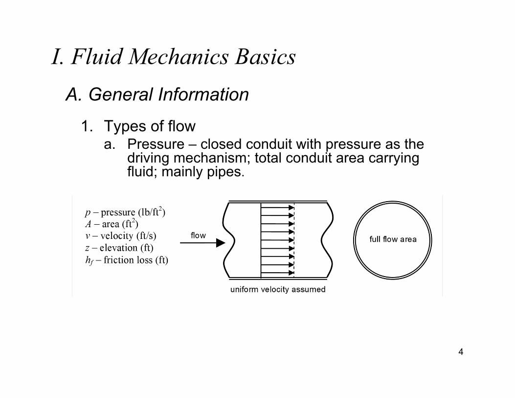
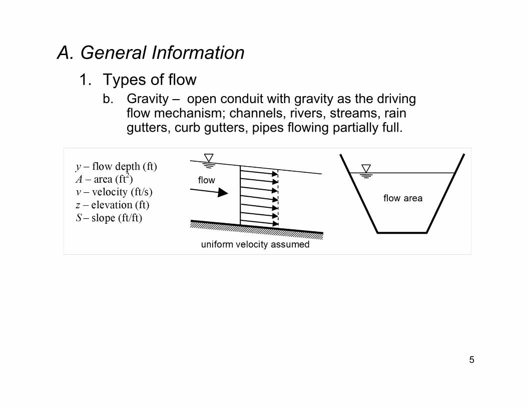
A. General Information
1. Types of flowa. Pressure – closed conduit with pressure as the
driving mechanism; total conduit area carrying fluid; mainly pipes.
4
I. Fluid Mechanics Basics
A. General Information1. Types of flow
b. Gravity – open conduit with gravity as the driving flow mechanism; channels, rivers, streams, rain gutters, curb gutters, pipes flowing partially full.
5
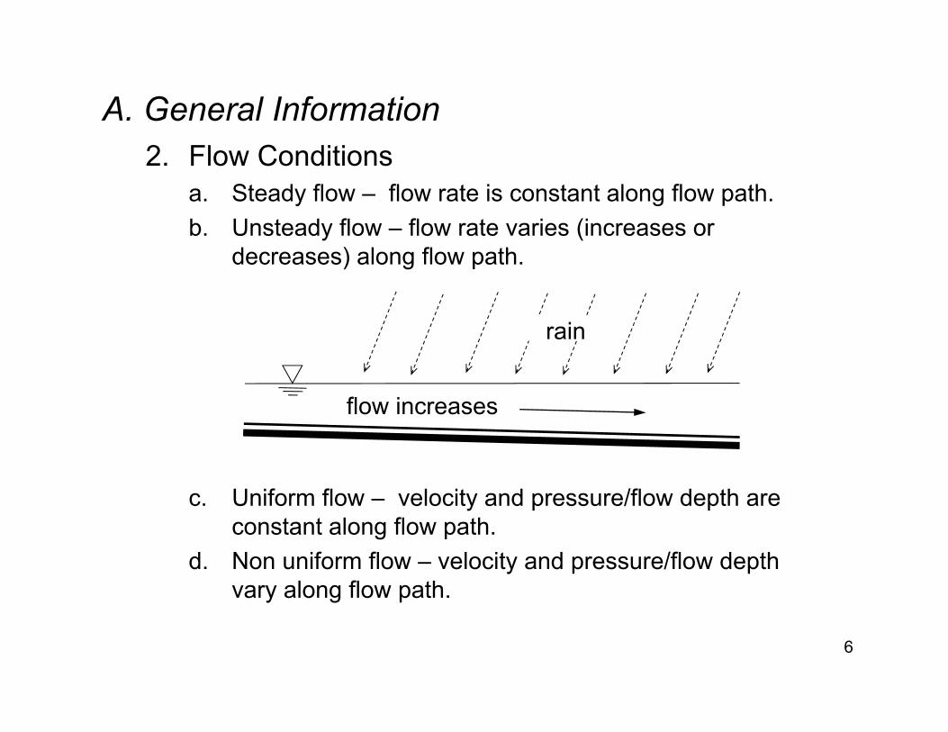
A. General Information2. Flow Conditions
a. Steady flow – flow rate is constant along flow path.b. Unsteady flow – flow rate varies (increases or
decreases) along flow path.
c. Uniform flow – velocity and pressure/flow depth are constant along flow path.
d. Non uniform flow – velocity and pressure/flow depth vary along flow path.
6
rain
flow increases
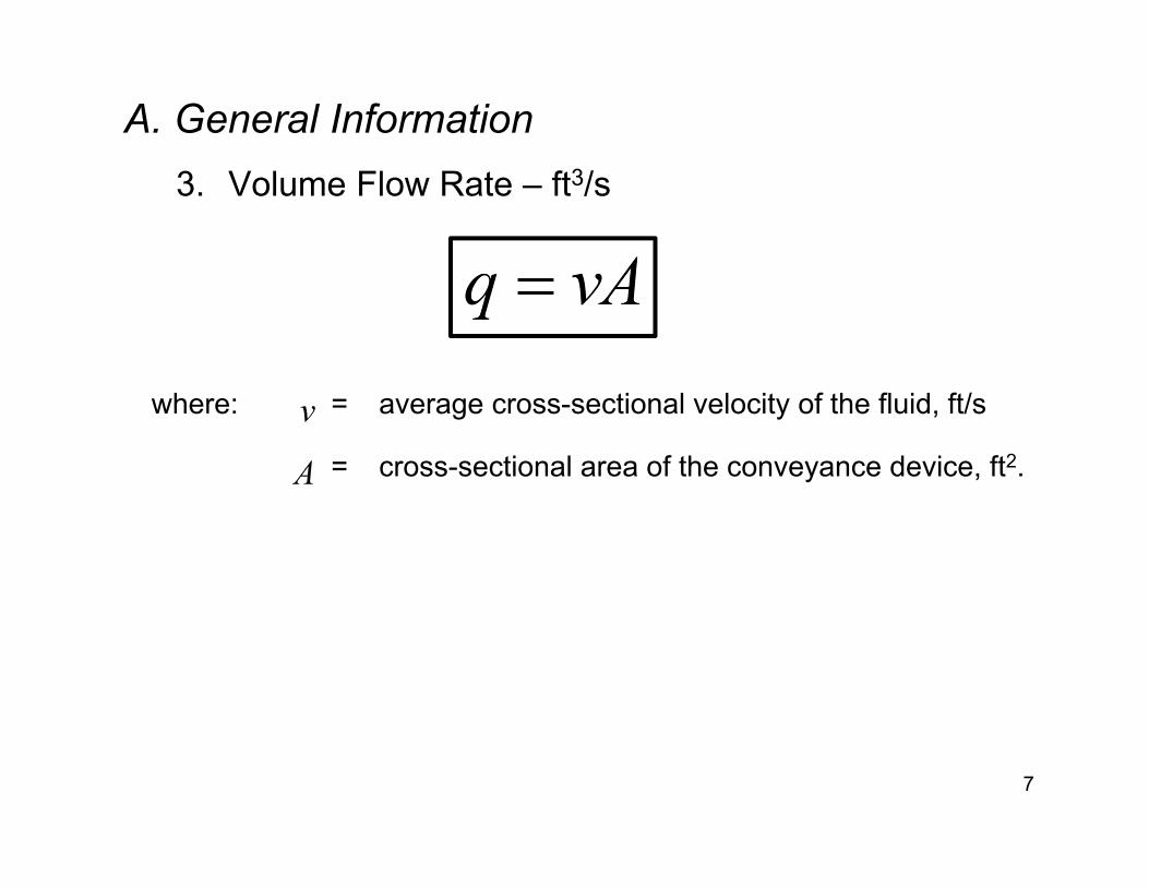
A. General Information3. Volume Flow Rate – ft3/s
7
where: v = average cross-sectional velocity of the fluid, ft/s
A = cross-sectional area of the conveyance device, ft2.
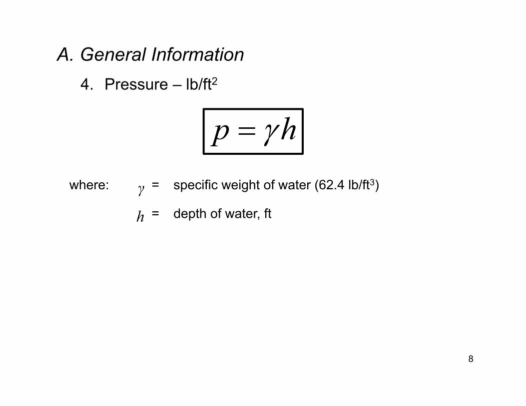
A. General Information4. Pressure – lb/ft2
8
where: γ = specific weight of water (62.4 lb/ft3)
h = depth of water, ft

B. Conservation of Mass1. For any control volume, surface or system
9
where qin = flow rate into the system (ft3/s)
qout = flow rate out of the system (ft3/s)
S/t = change is storage in system with respect to time (ft3/s)
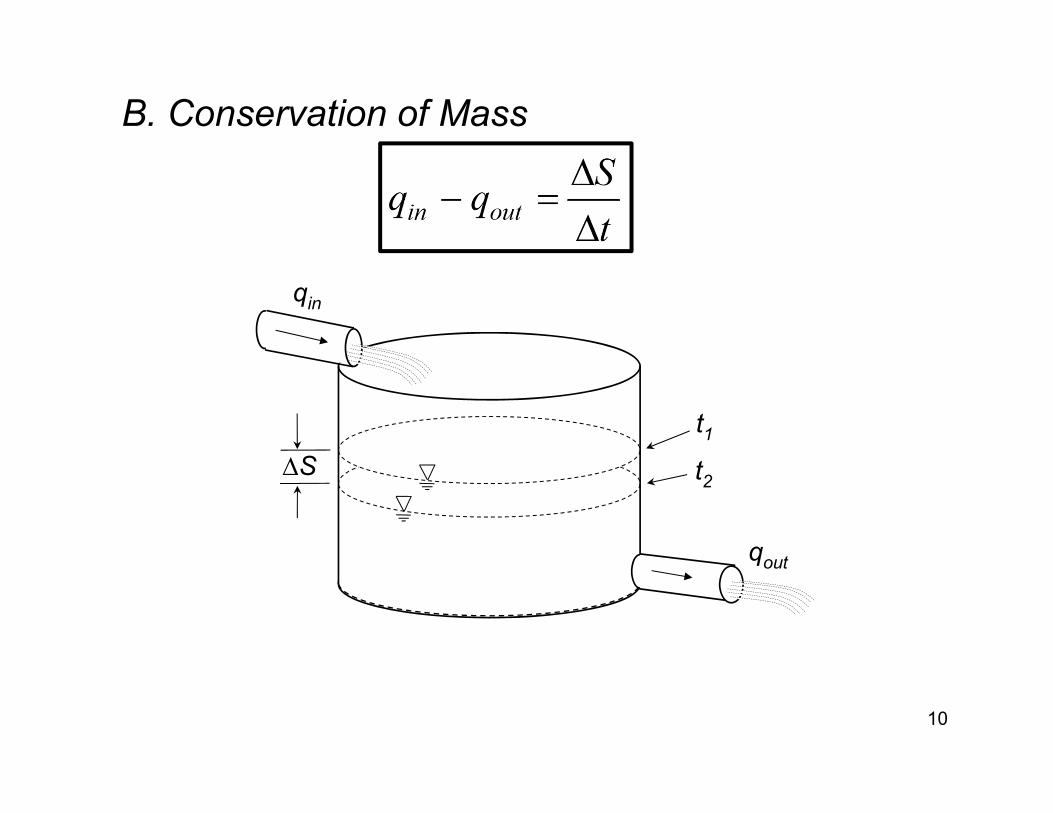
B. Conservation of Mass
10
qin
qout
∆St1t2
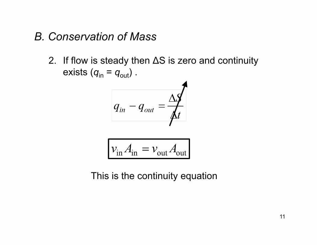
B. Conservation of Mass
2. If flow is steady then ΔS is zero and continuity exists (qin = qout) .
11
This is the continuity equation
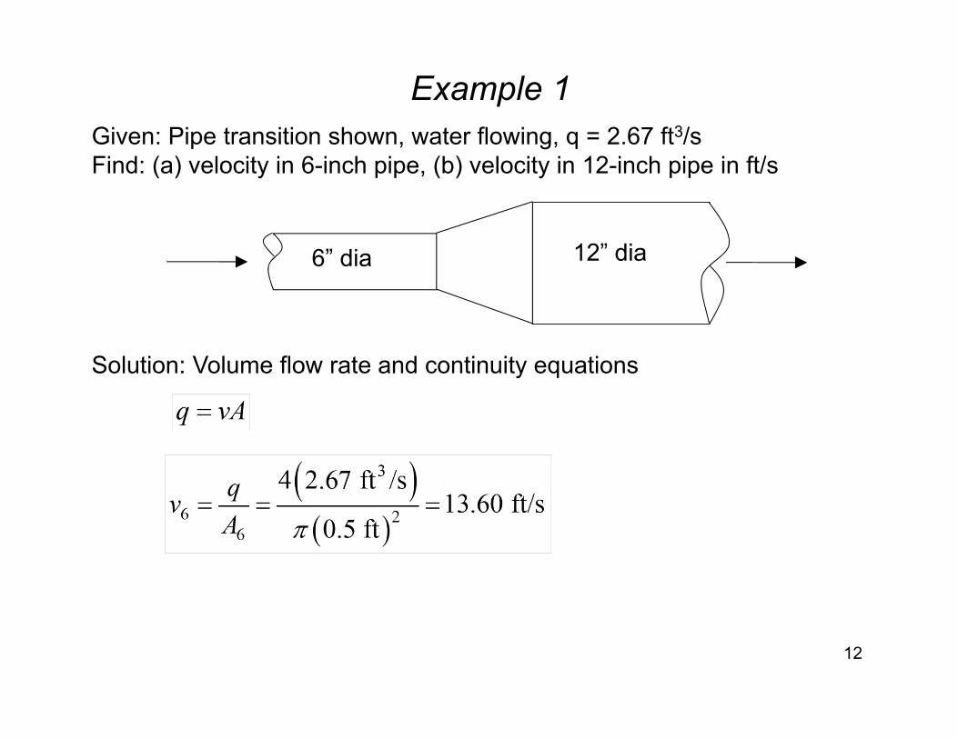
Example 1
12
6” dia 12” dia
Given: Pipe transition shown, water flowing, q = 2.67 ft3/sFind: (a) velocity in 6-inch pipe, (b) velocity in 12-inch pipe in ft/s
Solution: Volume flow rate and continuity equations
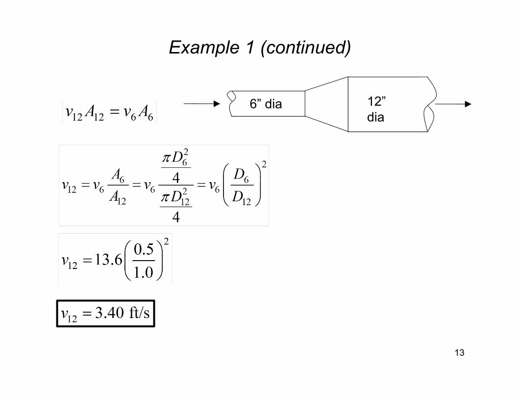
Example 1 (continued)
13
6” dia 12” dia
Example 2
14
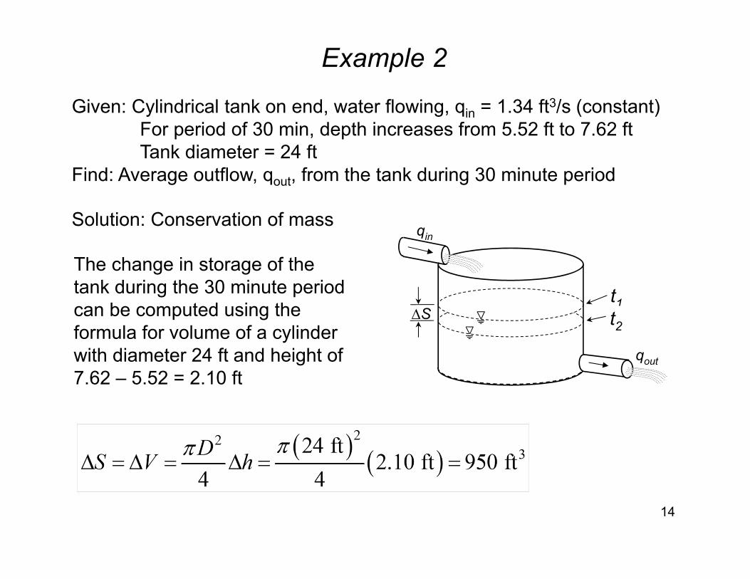
Given: Cylindrical tank on end, water flowing, qin = 1.34 ft3/s (constant)For period of 30 min, depth increases from 5.52 ft to 7.62 ftTank diameter = 24 ft
Find: Average outflow, qout, from the tank during 30 minute period
Solution: Conservation of mass
The change in storage of the tank during the 30 minute period can be computed using the formula for volume of a cylinder with diameter 24 ft and height of 7.62 – 5.52 = 2.10 ft
qin
qout
∆St1t2

Example 2 (continued)
15
qin
qout
∆St1t2
Solve for qout using conservation of mass
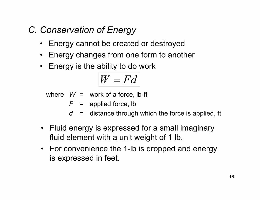
C. Conservation of Energy• Energy cannot be created or destroyed• Energy changes from one form to another• Energy is the ability to do work
16
where W = work of a force, lb-ftF = applied force, lbd = distance through which the force is applied, ft
• Fluid energy is expressed for a small imaginary fluid element with a unit weight of 1 lb.
• For convenience the 1-lb is dropped and energy is expressed in feet.
C. Conservation of Energy
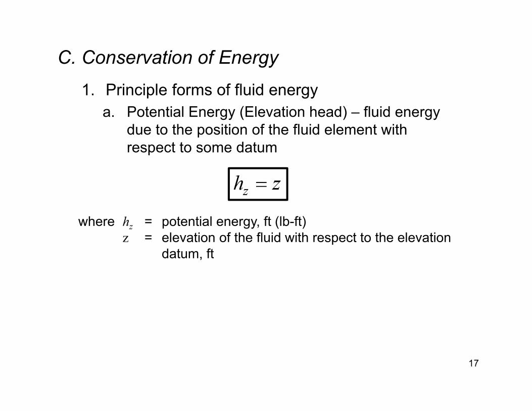
1. Principle forms of fluid energya. Potential Energy (Elevation head) – fluid energy
due to the position of the fluid element with respect to some datum
17
where hz = potential energy, ft (lb-ft)z = elevation of the fluid with respect to the elevation
datum, ft
C. Conservation of Energy1. Principle forms of fluid energy
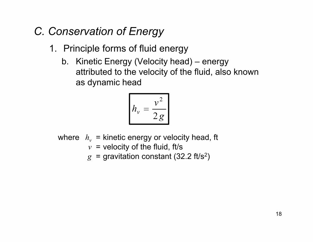
b. Kinetic Energy (Velocity head) – energy attributed to the velocity of the fluid, also known as dynamic head
18
where hv = kinetic energy or velocity head, ftv = velocity of the fluid, ft/sg = gravitation constant (32.2 ft/s2)
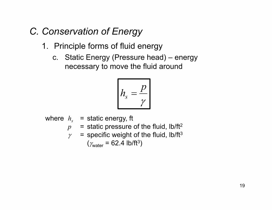
C. Conservation of Energy1. Principle forms of fluid energy
c. Static Energy (Pressure head) – energy necessary to move the fluid around
19
where hs = static energy, ftp = static pressure of the fluid, lb/ft2 = specific weight of the fluid, lb/ft3
(water = 62.4 lb/ft3)
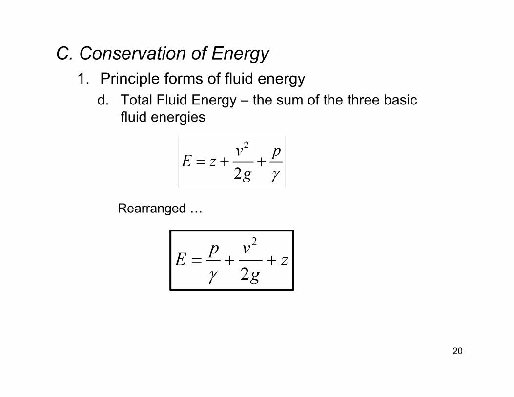
C. Conservation of Energy1. Principle forms of fluid energy
d. Total Fluid Energy – the sum of the three basic fluid energies
20
Rearranged …
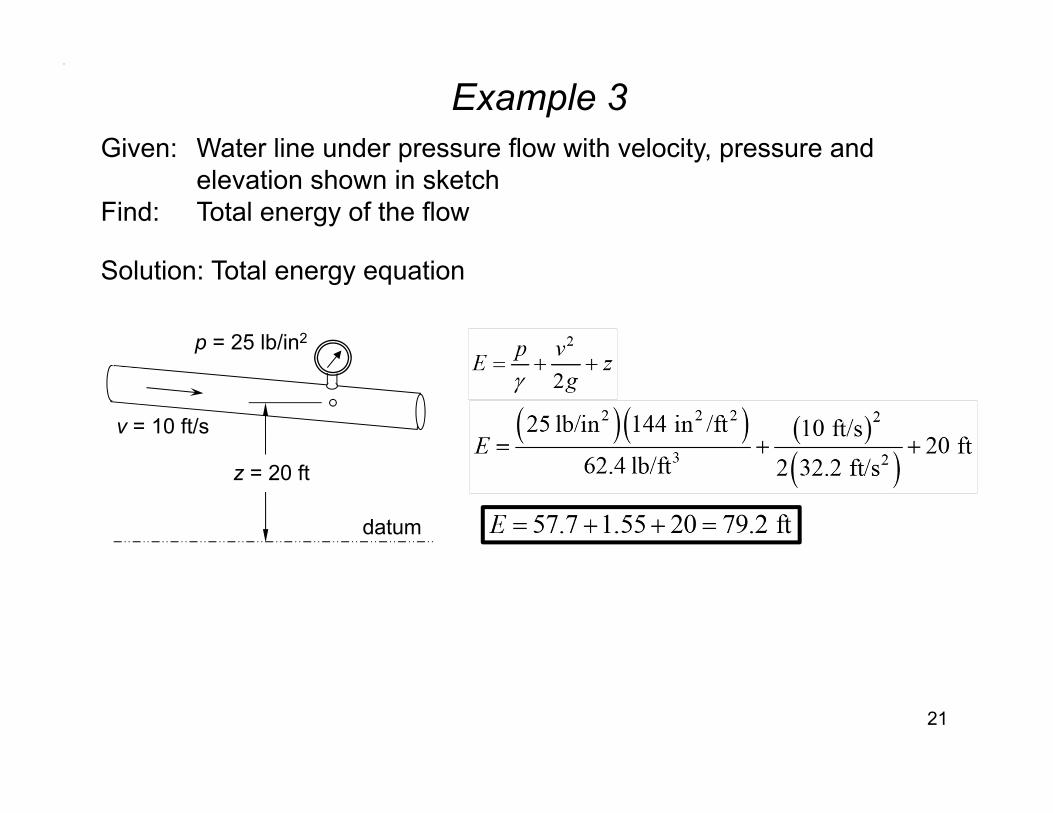
Example 3
21
Given: Water line under pressure flow with velocity, pressure and elevation shown in sketch
Find: Total energy of the flow
Solution: Total energy equation
datum
v = 10 ft/s
p = 25 lb/in2
z = 20 ft

Example 4
22
Given: Gravity flow in a channel with depth, velocity and elevationshown in sketch
Find: Total energy of the flow
Solution: Total energy equation
datum
v = 5 ft/s
z = 30 ft
y = 8 ft
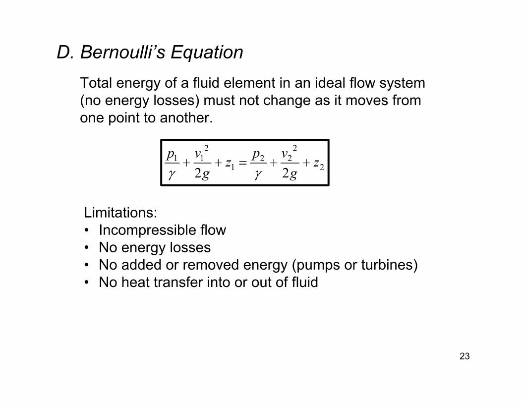
D. Bernoulli’s EquationTotal energy of a fluid element in an ideal flow system (no energy losses) must not change as it moves from one point to another.
23
Limitations:• Incompressible flow• No energy losses• No added or removed energy (pumps or turbines)• No heat transfer into or out of fluid

Example 5
24
Given: Horizontal pipe, q = 2.8 ft3/s, ideal flow of waterFind: Change in pressure from 6-inch pipe to 12-inch pipe
Solution: Continuity and Bernoulli’s equation
6” dia 12” dia
Continuity:
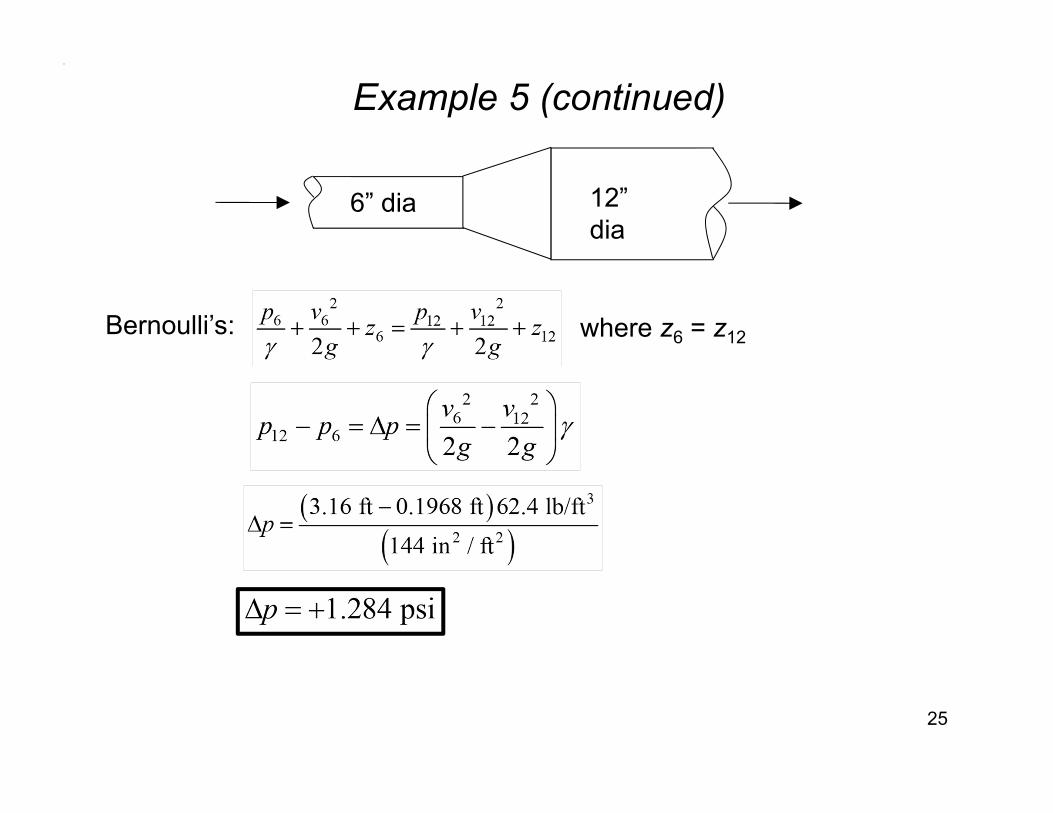
Example 5 (continued)
25
6” dia 12” dia
Bernoulli’s: where z6 = z12
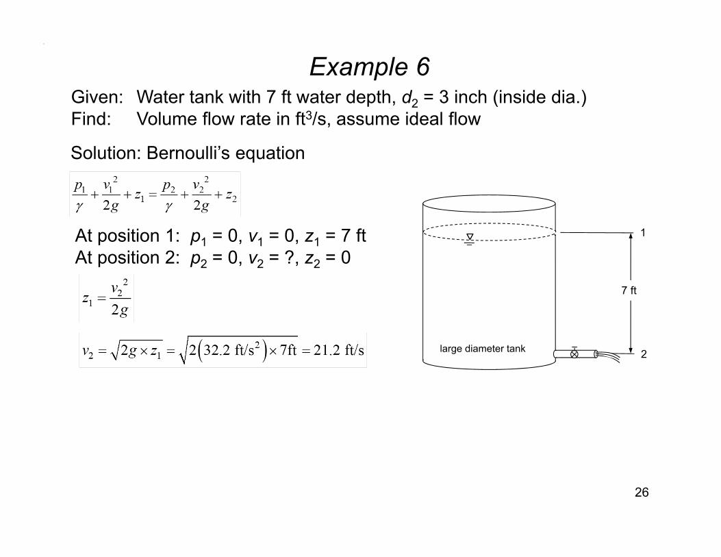
Example 6
26
Given: Water tank with 7 ft water depth, d2 = 3 inch (inside dia.)Find: Volume flow rate in ft3/s, assume ideal flow
Solution: Bernoulli’s equation
At position 1: p1 = 0, v1 = 0, z1 = 7 ftAt position 2: p2 = 0, v2 = ?, z2 = 0
7 ft
large diameter tank 2
1
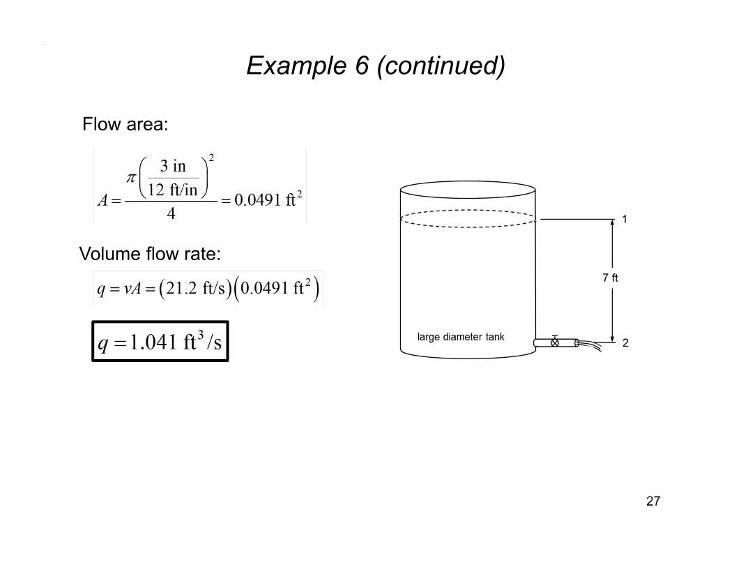
Example 6 (continued)
27
Flow area:
Volume flow rate:
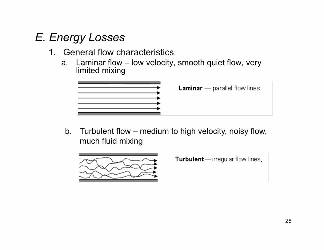
E. Energy Losses1. General flow characteristics
a. Laminar flow – low velocity, smooth quiet flow, very limited mixing
28
b. Turbulent flow – medium to high velocity, noisy flow, much fluid mixing
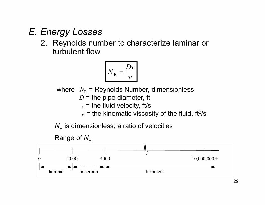
E. Energy Losses2. Reynolds number to characterize laminar or
turbulent flow
29
where NR = Reynolds Number, dimensionlessD = the pipe diameter, ftv = the fluid velocity, ft/s = the kinematic viscosity of the fluid, ft2/s.
NR is dimensionless; a ratio of velocities
Range of NR
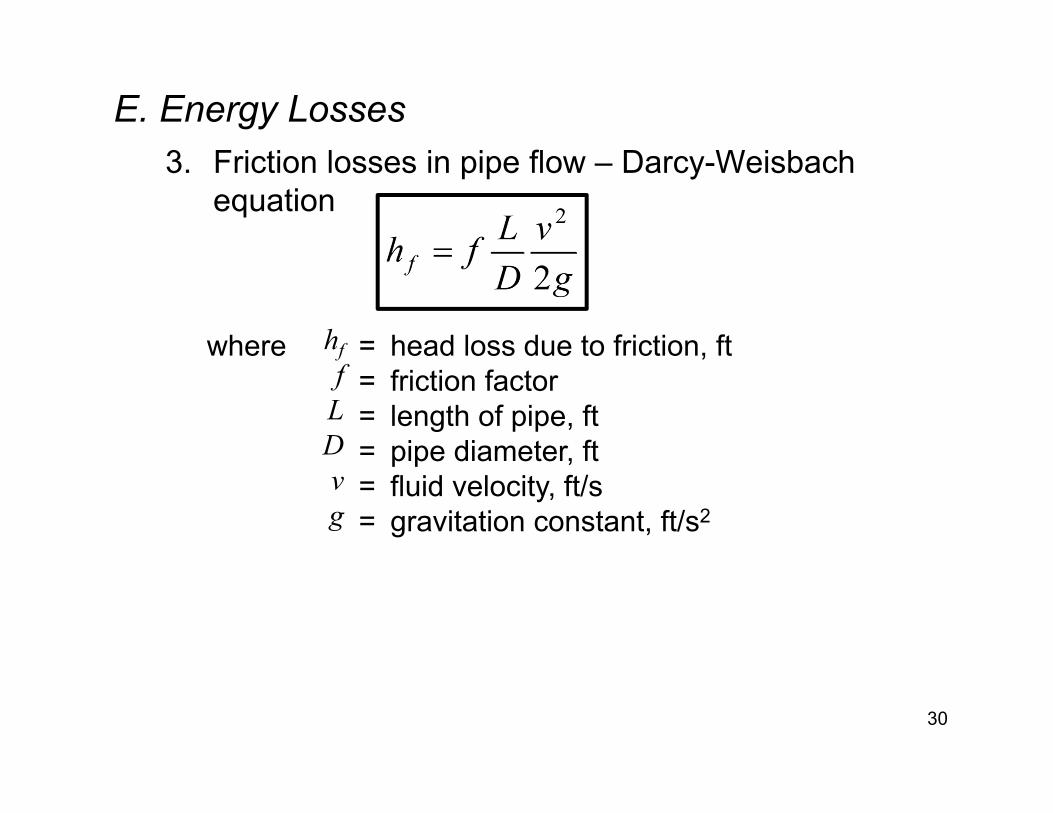
E. Energy Losses3. Friction losses in pipe flow – Darcy-Weisbach
equation
30
where hf = head loss due to friction, ftf = friction factor
L = length of pipe, ftD = pipe diameter, ftv = fluid velocity, ft/sg = gravitation constant, ft/s2
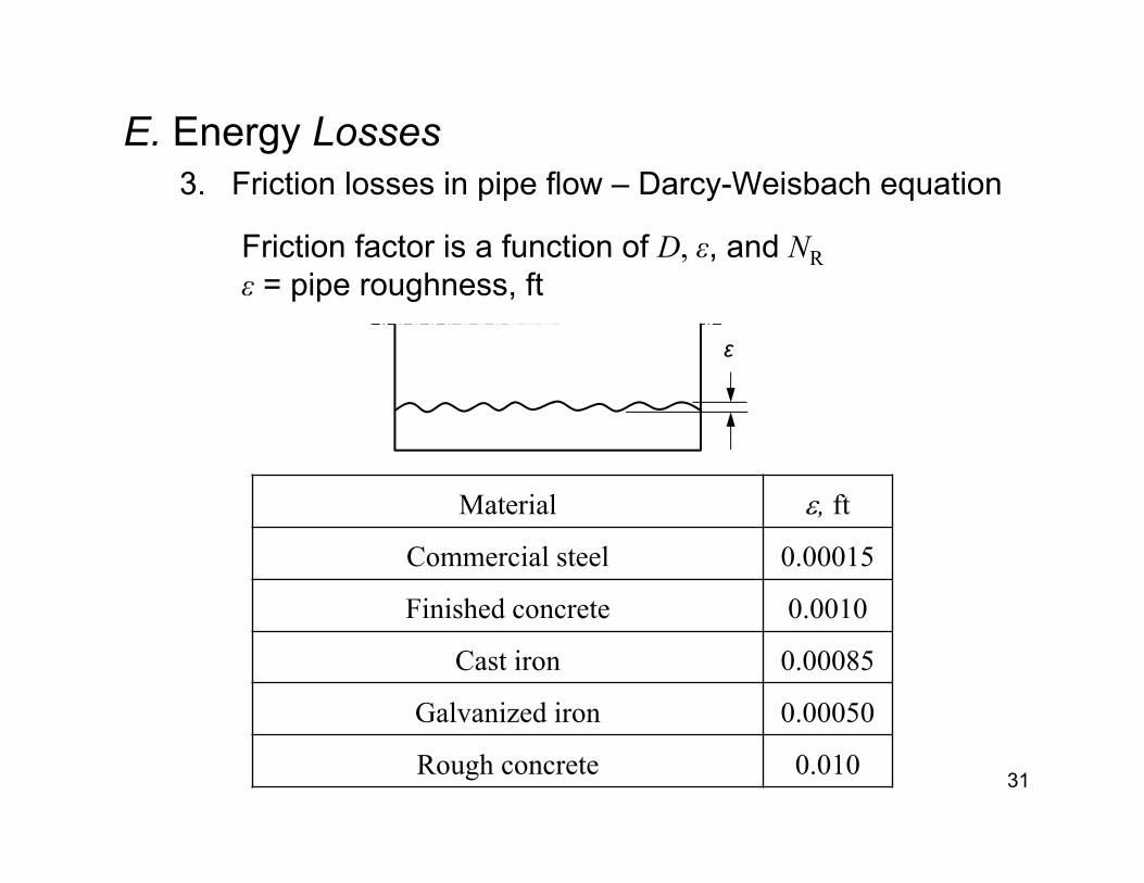
E. Energy Losses3. Friction losses in pipe flow – Darcy-Weisbach equation
31
Friction factor is a function of D, ε, and NRε = pipe roughness, ft
ε
Material , ft
Commercial steel 0.00015
Finished concrete 0.0010
Cast iron 0.00085
Galvanized iron 0.00050
Rough concrete 0.010
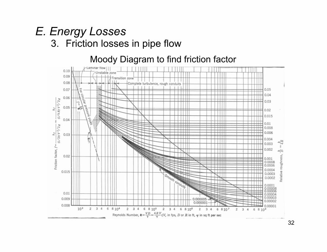
E. Energy Losses3. Friction losses in pipe flow
32
Moody Diagram to find friction factor
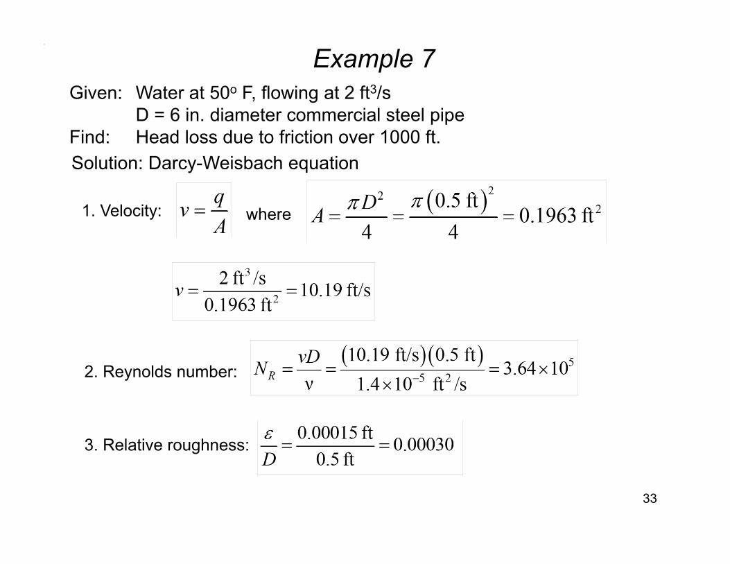
Example 7
33
Given: Water at 50o F, flowing at 2 ft3/sD = 6 in. diameter commercial steel pipe
Find: Head loss due to friction over 1000 ft.Solution: Darcy-Weisbach equation
1. Velocity: where
2. Reynolds number:
3. Relative roughness:
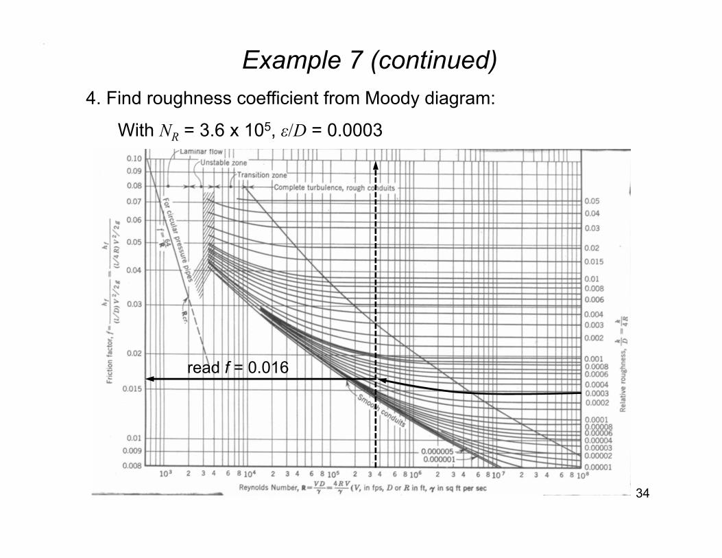
Example 7 (continued)
34
4. Find roughness coefficient from Moody diagram:
With NR = 3.6 x 10⁵, ε/D = 0.0003
read f = 0.016
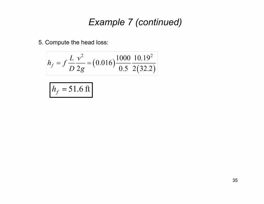
Example 7 (continued)
35
5. Compute the head loss:
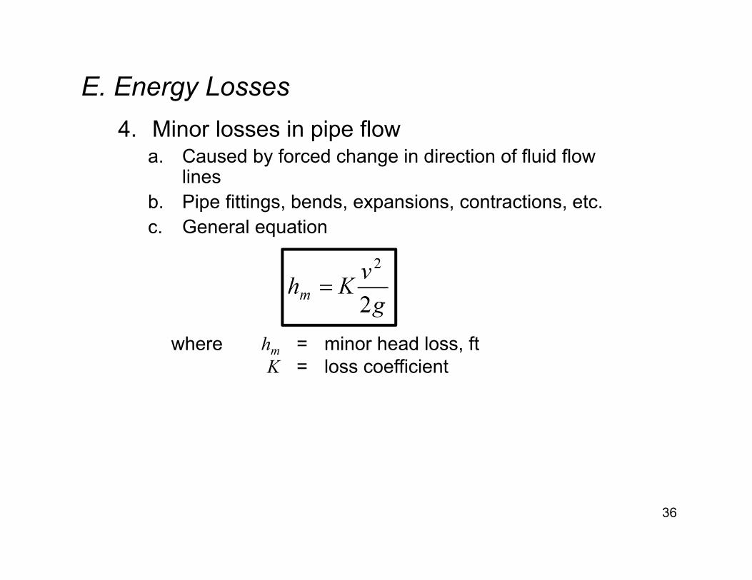
E. Energy Losses4. Minor losses in pipe flow
a. Caused by forced change in direction of fluid flow lines
b. Pipe fittings, bends, expansions, contractions, etc.c. General equation
36
where hm = minor head loss, ftK = loss coefficient

E. Energy Losses4. Minor losses in pipe flow
d. Loss coefficients1) Pipe Fittings
37
Fitting type KStandard 90o bend 0.9Standard tee 1.8Gate valve (fully open) 0.2Globe valve (fully open) 10.0

E. Energy Losses
4. Minor losses in pipe flowd. Loss coefficients
2) Exit loss
38
Large tankK = 1.0

E. Energy Losses4. Minor losses in pipe flow
d. Loss coefficients3) Entrance loss
39
Large tank
(a) ProjectingK = 1.0
(c) rounded K = 0.04
(b) square edgeK = 0.5
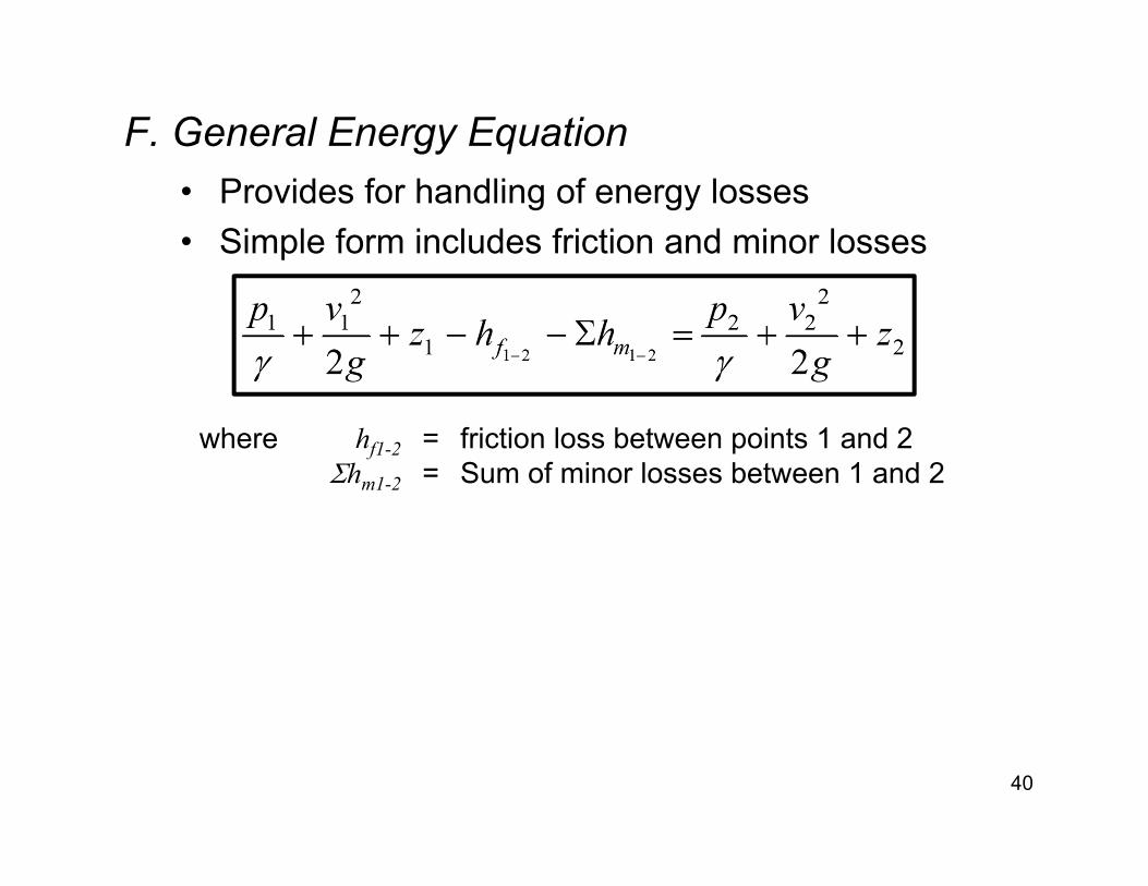
F. General Energy Equation• Provides for handling of energy losses• Simple form includes friction and minor losses
40
where hf1-2 = friction loss between points 1 and 2hm1-2 = Sum of minor losses between 1 and 2
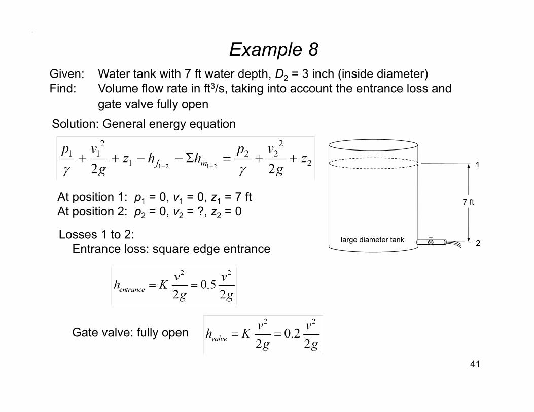
Example 8
41
Given: Water tank with 7 ft water depth, D2 = 3 inch (inside diameter)Find: Volume flow rate in ft3/s, taking into account the entrance loss and
gate valve fully openSolution: General energy equation
Gate valve: fully open
At position 1: p1 = 0, v1 = 0, z1 = 7 ftAt position 2: p2 = 0, v2 = ?, z2 = 0
Losses 1 to 2:Entrance loss: square edge entrance
7 ft
large diameter tank 2
1
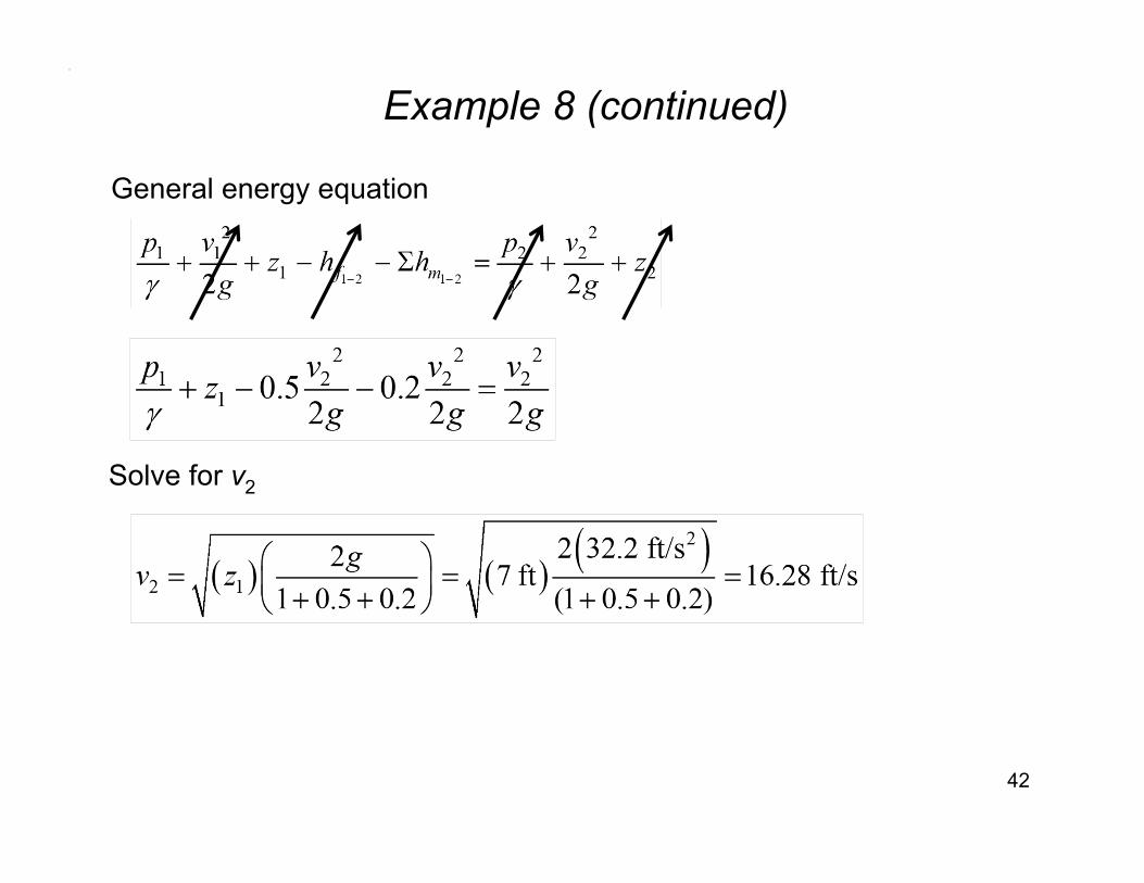
Example 8 (continued)
42
General energy equation
Solve for v2
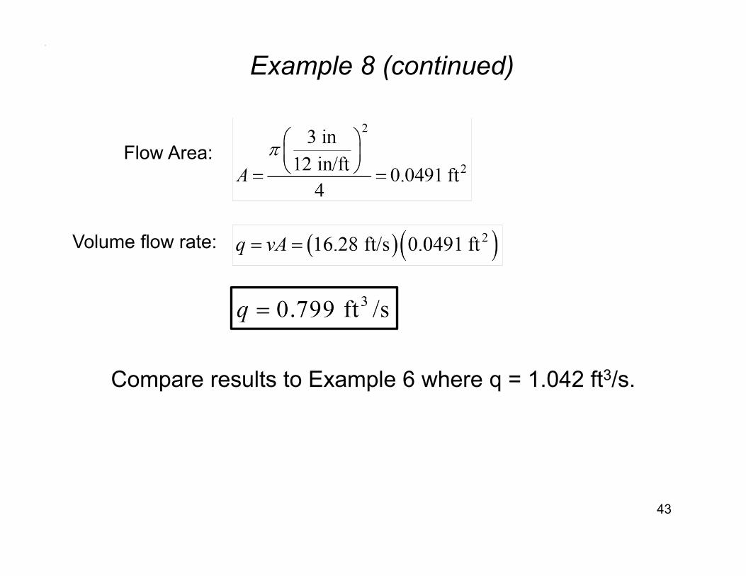
Example 8 (continued)
43
Flow Area:
Volume flow rate:
Compare results to Example 6 where q = 1.042 ft3/s.
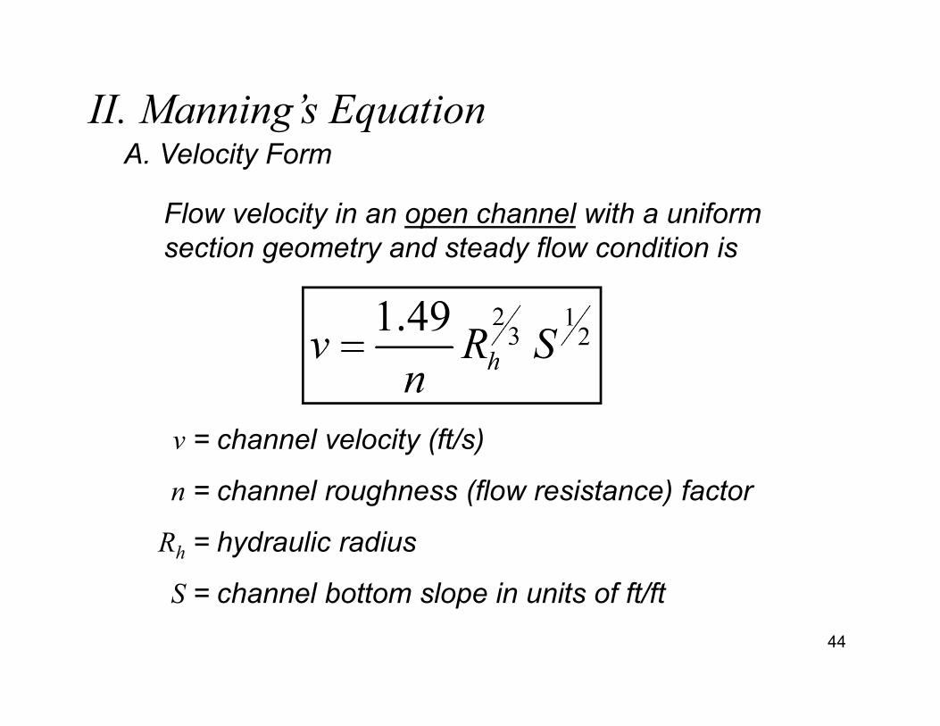
II. Manning’s Equation
Flow velocity in an open channel with a uniform section geometry and steady flow condition is
v = channel velocity (ft/s)
n = channel roughness (flow resistance) factor
Rh = hydraulic radius
S = channel bottom slope in units of ft/ft44
A. Velocity Form
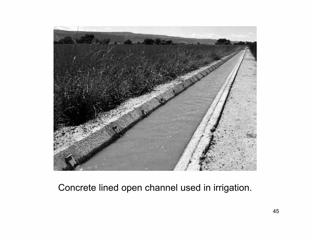
Concrete lined open channel used in irrigation.
45
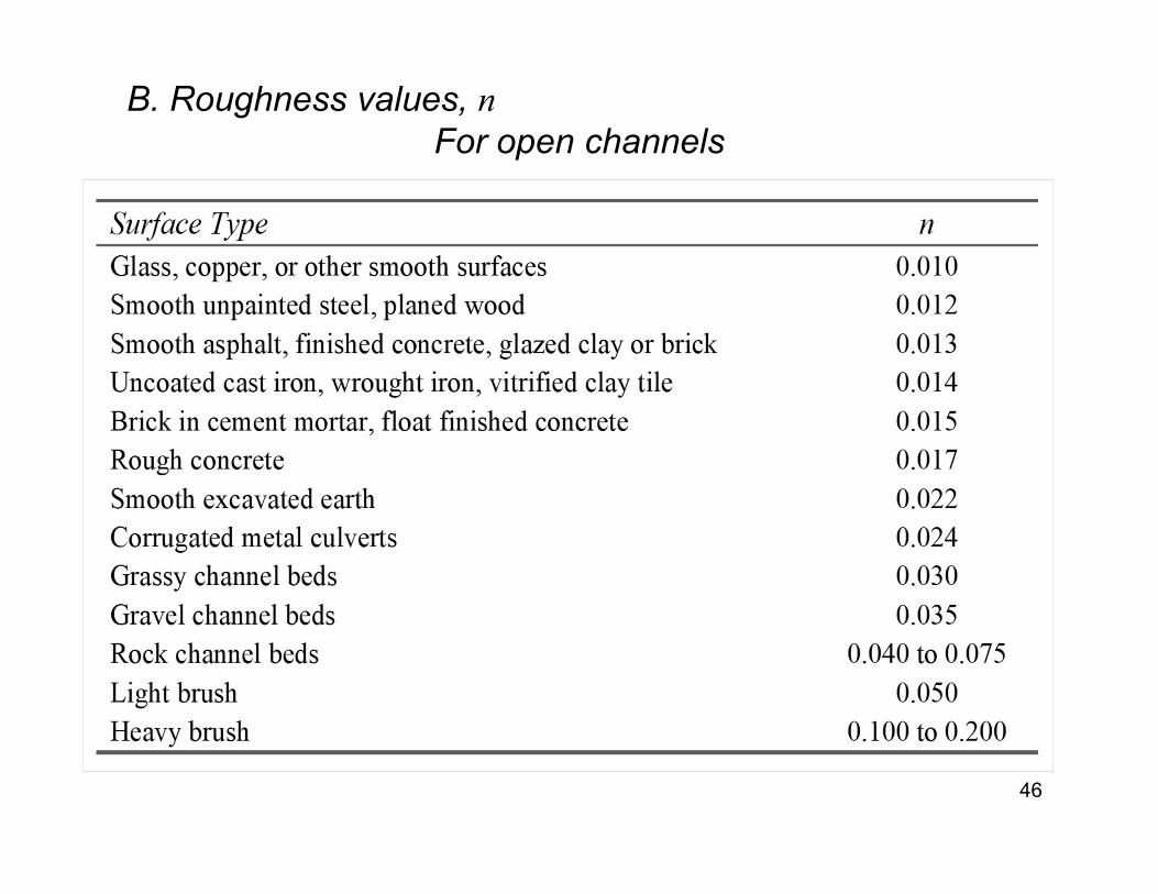
B. Roughness values, nFor open channels
46
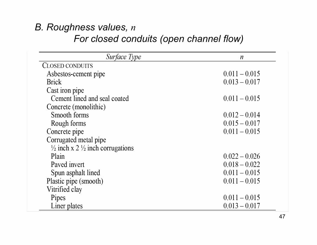
47
B. Roughness values, nFor closed conduits (open channel flow)
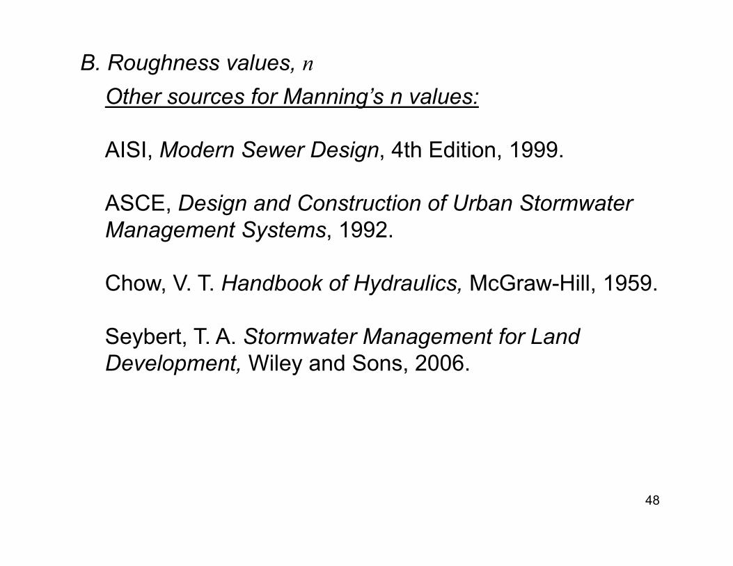
Other sources for Manning’s n values:
AISI, Modern Sewer Design, 4th Edition, 1999.
ASCE, Design and Construction of Urban StormwaterManagement Systems, 1992.
Chow, V. T. Handbook of Hydraulics, McGraw-Hill, 1959.
Seybert, T. A. Stormwater Management for Land Development, Wiley and Sons, 2006.
48
B. Roughness values, n
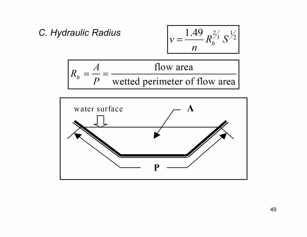
C. Hydraulic Radius
49
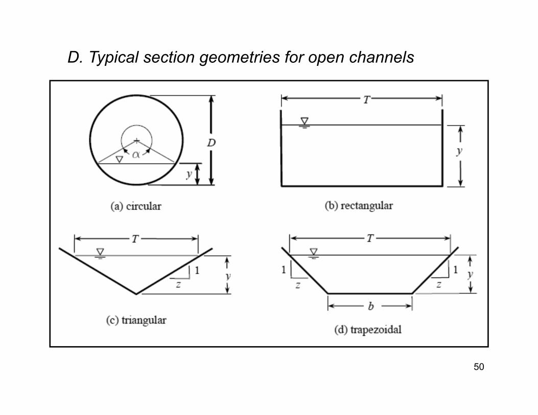
D. Typical section geometries for open channels
50
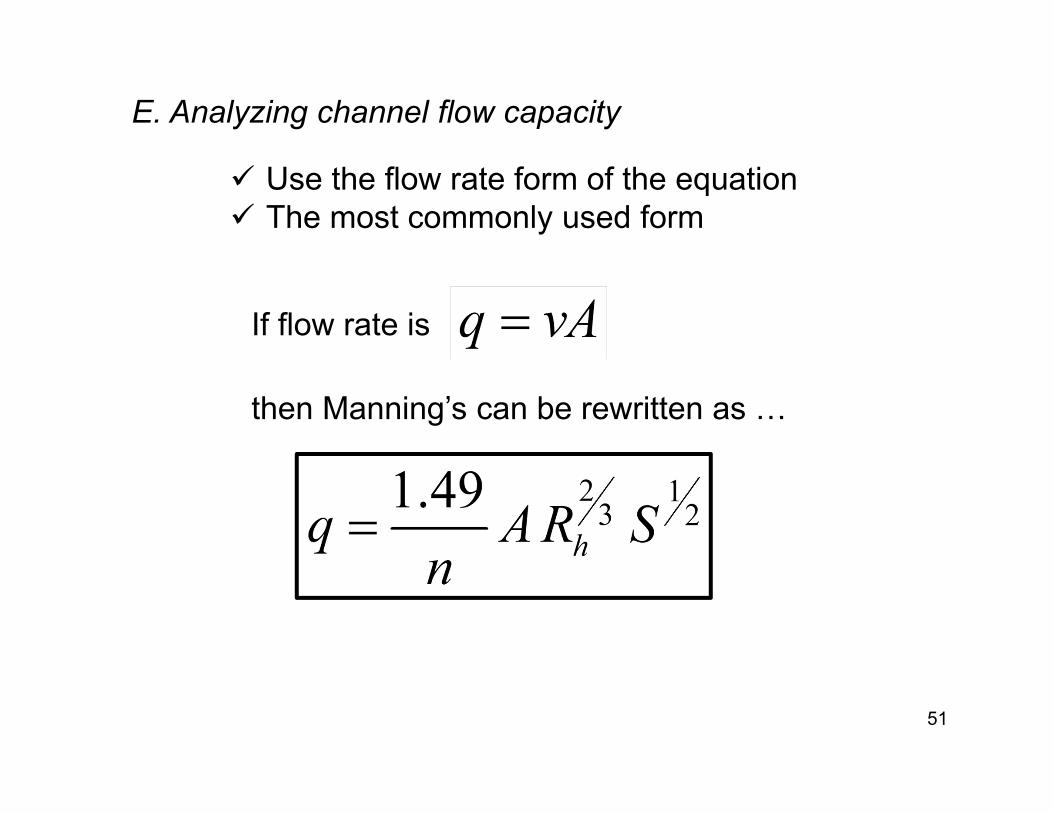
E. Analyzing channel flow capacity
51
Use the flow rate form of the equation The most commonly used form
then Manning’s can be rewritten as …
If flow rate is
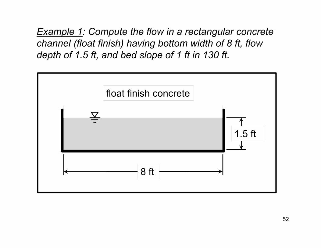
Example 1: Compute the flow in a rectangular concrete channel (float finish) having bottom width of 8 ft, flow depth of 1.5 ft, and bed slope of 1 ft in 130 ft.
52
1.5 ft
8 ft
float finish concrete

Example 1: To start, select n; compute flow area, wetted perimeter and hydraulic radius.
Flow area:
Hydraulic Radius:
Wetted perimeter:
53
Roughness, n: float finish concrete is about 0.015
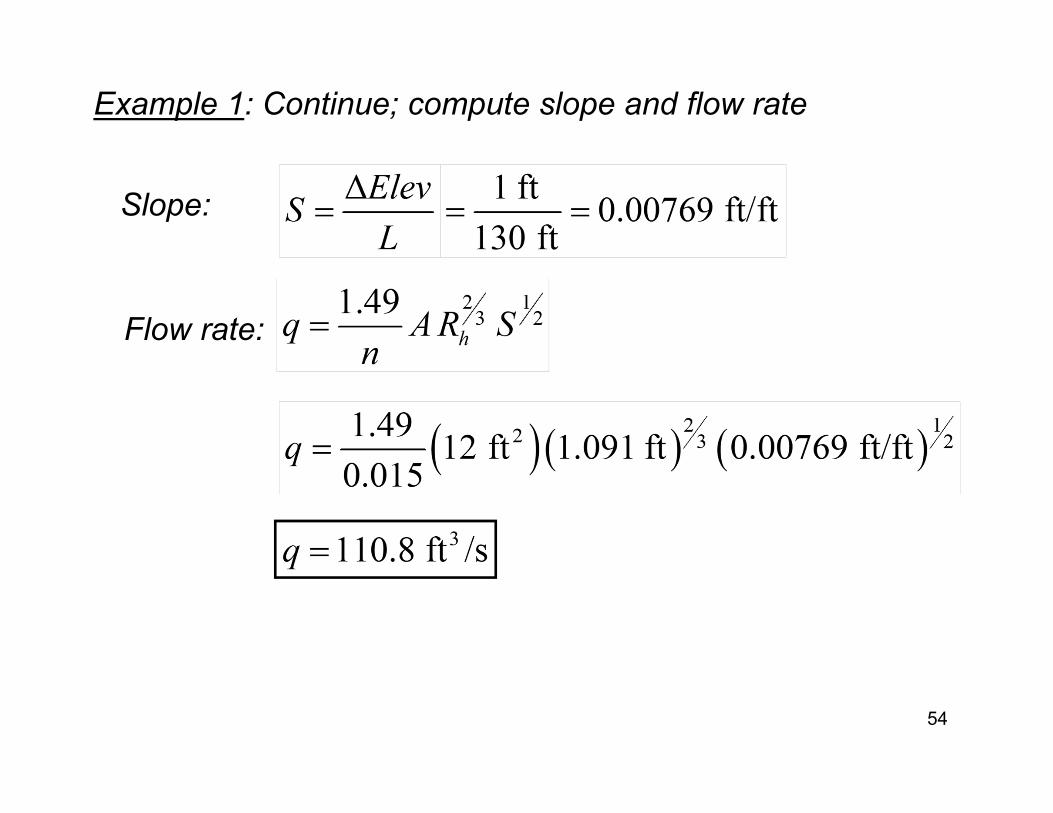
Example 1: Continue; compute slope and flow rate
Slope:
Flow rate:
54
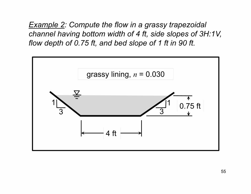
Example 2: Compute the flow in a grassy trapezoidal channel having bottom width of 4 ft, side slopes of 3H:1V, flow depth of 0.75 ft, and bed slope of 1 ft in 90 ft.
55
0.75 ft
4 ft
grassy lining, n = 0.030
31 1
3
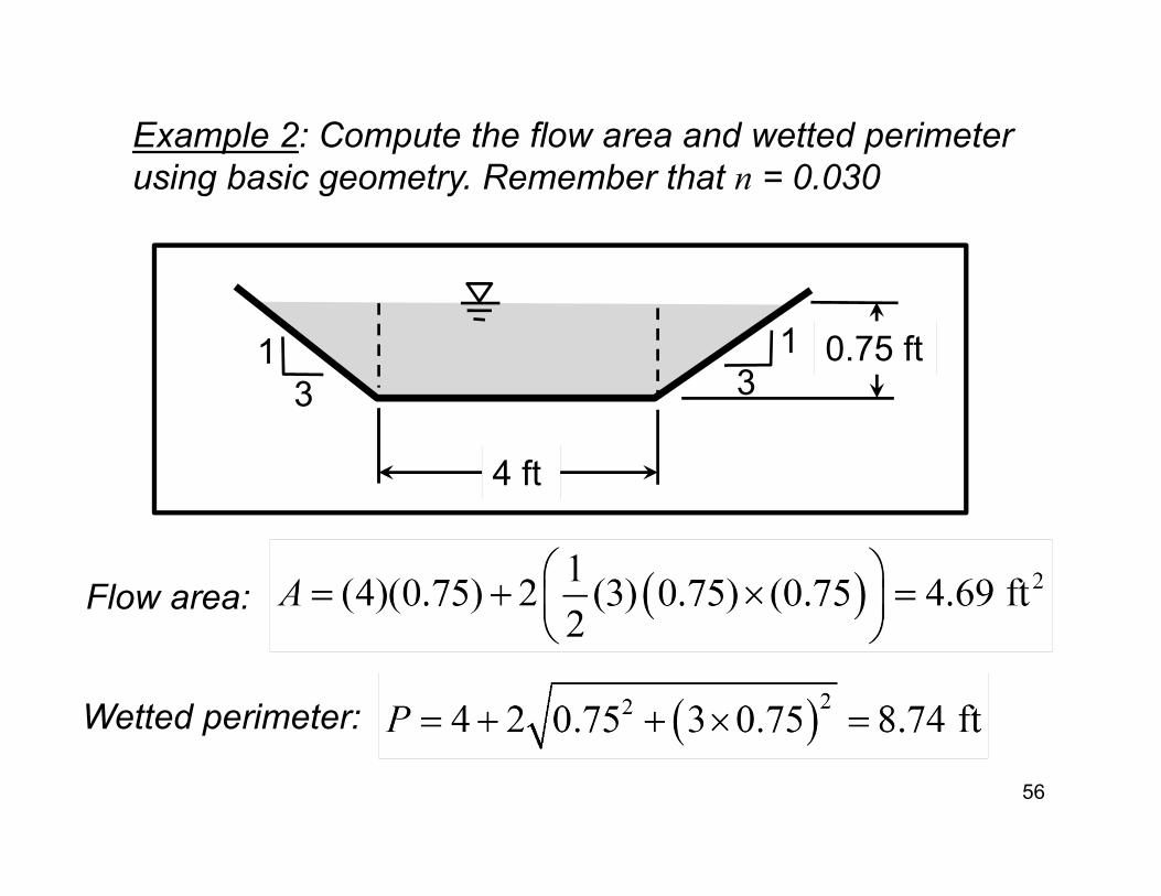
Example 2: Compute the flow area and wetted perimeter using basic geometry. Remember that n = 0.030
56
0.75 ft
4 ft
31 1
3
Flow area:
Wetted perimeter:
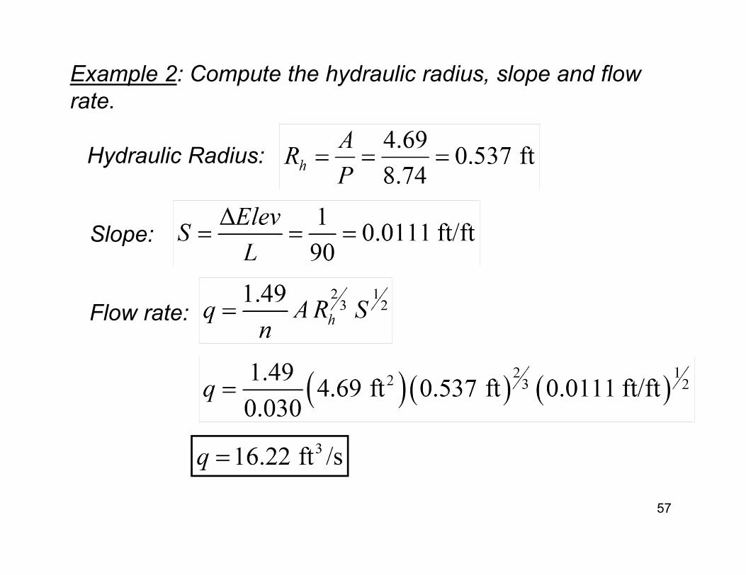
Example 2: Compute the hydraulic radius, slope and flow rate.
Hydraulic Radius:
57
Slope:
Flow rate:
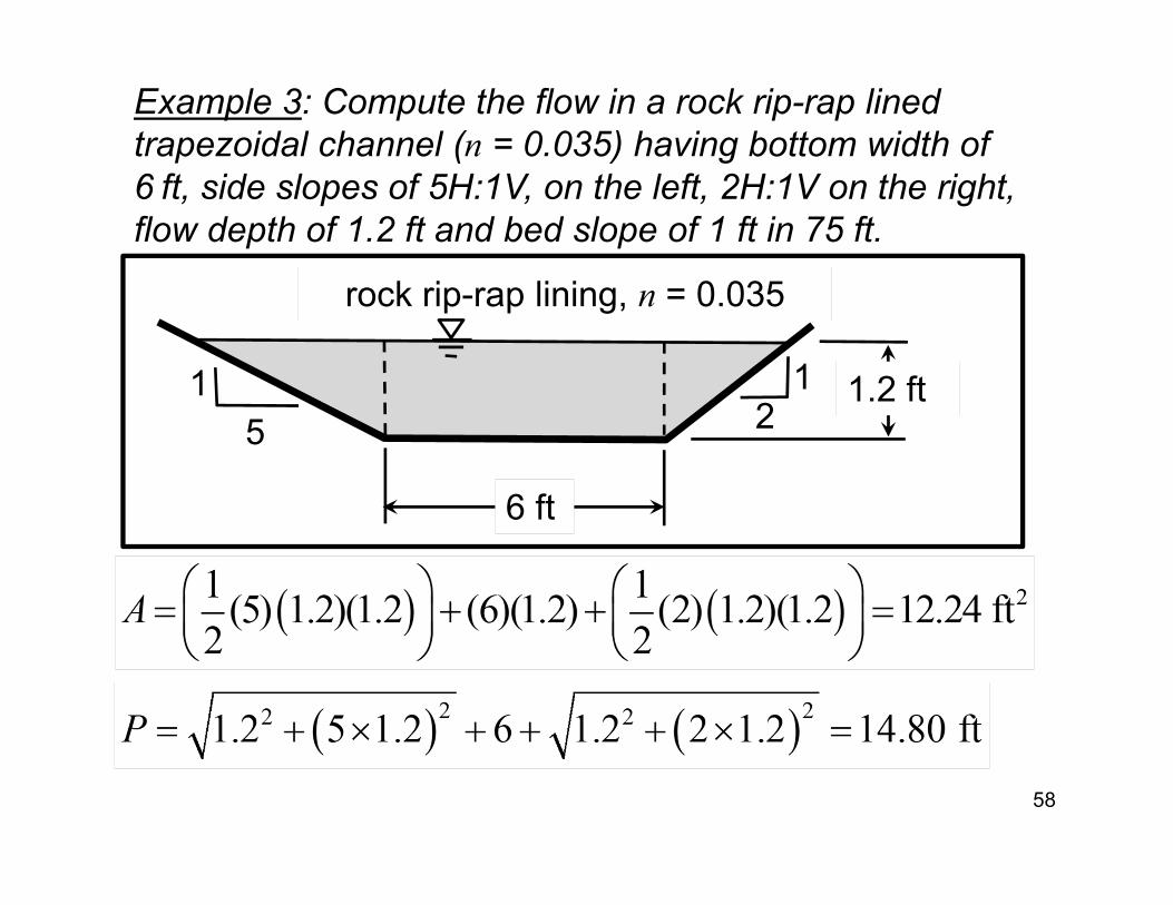
Example 3: Compute the flow in a rock rip-rap lined trapezoidal channel (n = 0.035) having bottom width of 6 ft, side slopes of 5H:1V, on the left, 2H:1V on the right, flow depth of 1.2 ft and bed slope of 1 ft in 75 ft.
58
1.2 ft
6 ft
rock rip-rap lining, n = 0.035
51 1
2
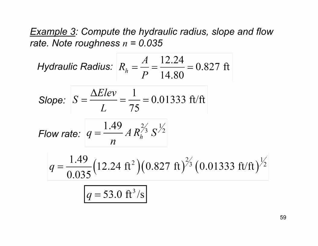
Example 3: Compute the hydraulic radius, slope and flow rate. Note roughness n = 0.035
Hydraulic Radius:
59
Slope:
Flow rate:
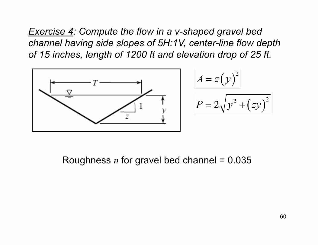
Exercise 4: Compute the flow in a v-shaped gravel bed channel having side slopes of 5H:1V, center-line flow depth of 15 inches, length of 1200 ft and elevation drop of 25 ft.
60
Roughness n for gravel bed channel = 0.035
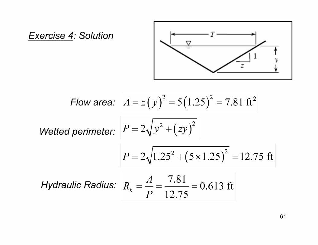
Exercise 4: Solution
Flow area:
Hydraulic Radius:
Wetted perimeter:
61
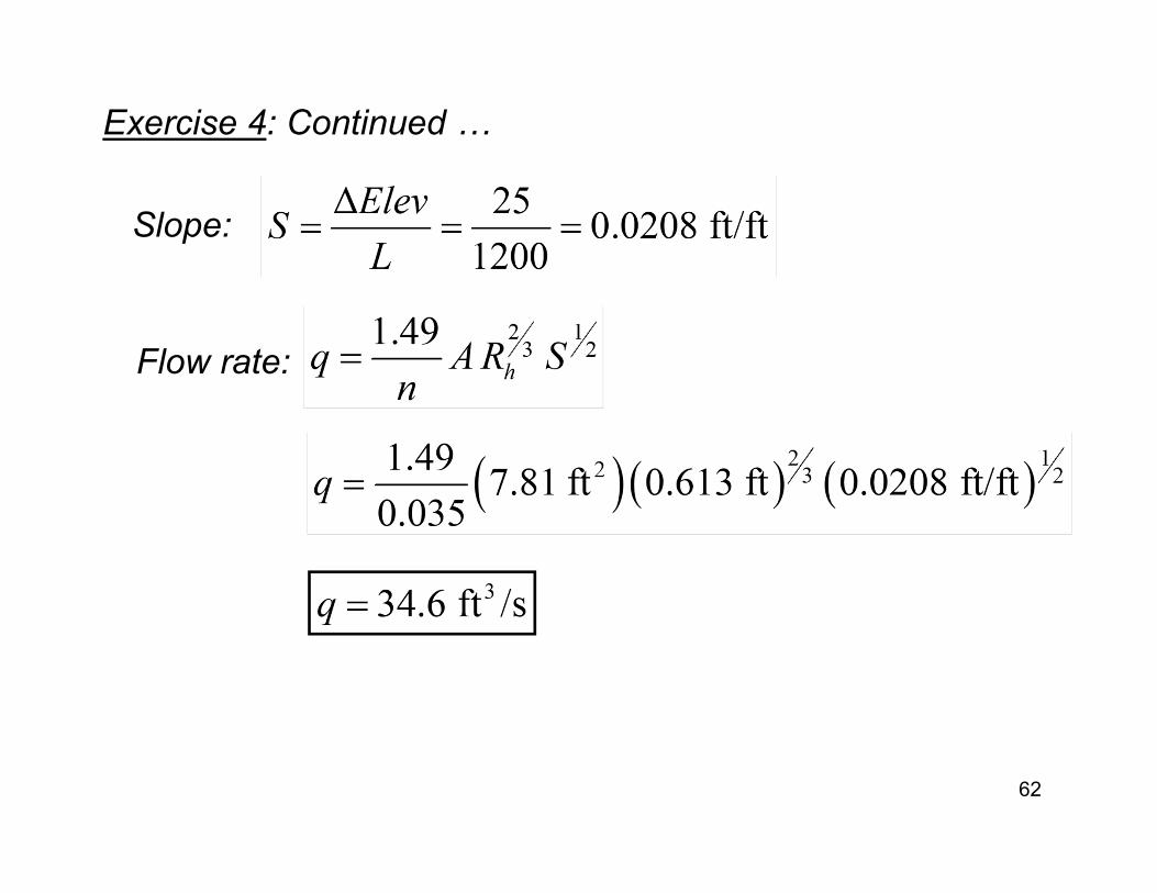
Exercise 4: Continued …
Slope:
Flow rate:
62
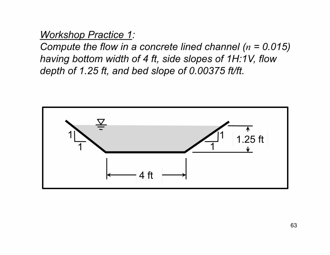
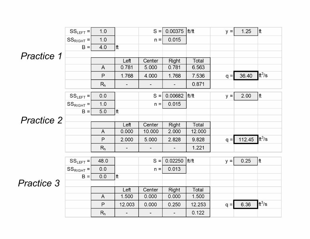
Workshop Practice 1:Compute the flow in a concrete lined channel (n = 0.015) having bottom width of 4 ft, side slopes of 1H:1V, flow depth of 1.25 ft, and bed slope of 0.00375 ft/ft.
63
1.25 ft
4 ft
11 1
1
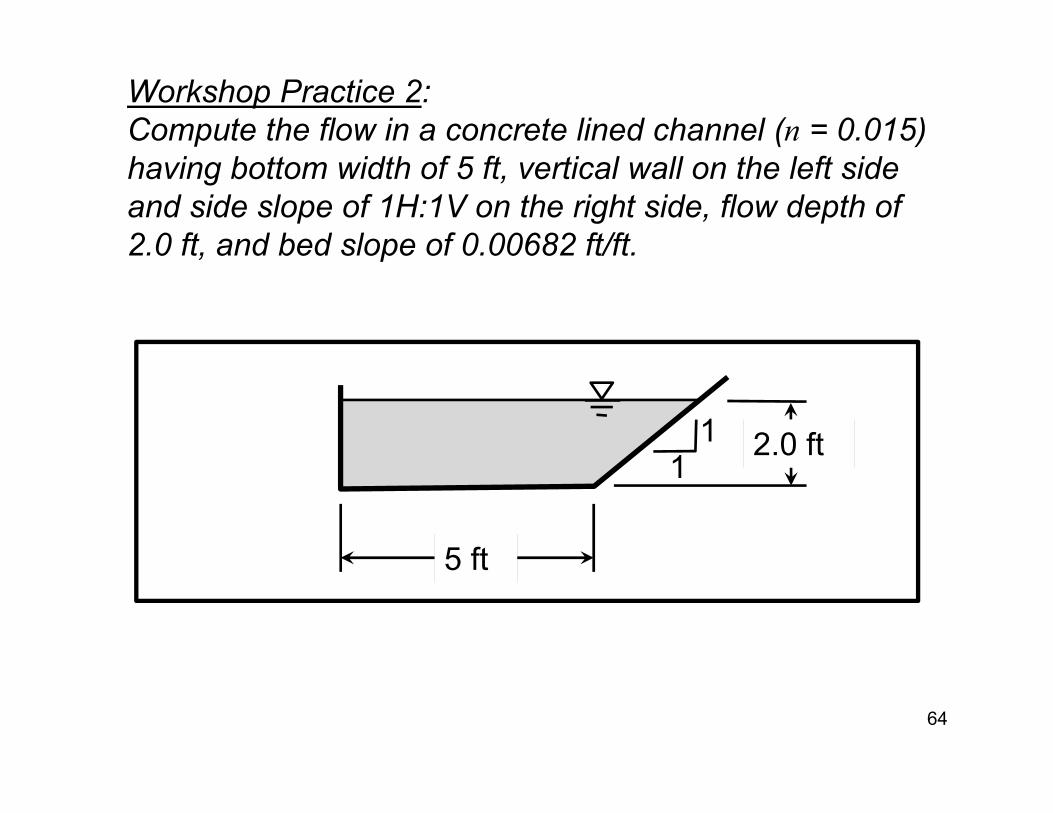
Workshop Practice 2:Compute the flow in a concrete lined channel (n = 0.015) having bottom width of 5 ft, vertical wall on the left side and side slope of 1H:1V on the right side, flow depth of 2.0 ft, and bed slope of 0.00682 ft/ft.
64
2.0 ft
5 ft
11

Workshop Practice 3:Determine the flow of a concrete street and curb gutter as shown in the figure. The flow-line slope is 0.0225 ft/ft.
65
66
Practice 1
Practice 2
Practice 3
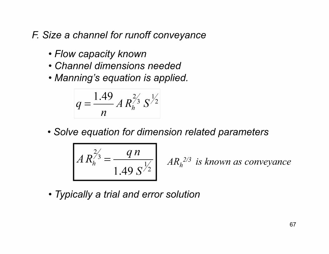
F. Size a channel for runoff conveyance
• Flow capacity known• Channel dimensions needed• Manning’s equation is applied.
• Solve equation for dimension related parameters
• Typically a trial and error solution
67
ARh2/3 is known as conveyance
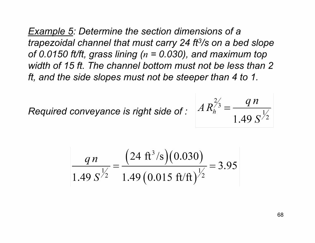
Example 5: Determine the section dimensions of a trapezoidal channel that must carry 24 ft3/s on a bed slope of 0.0150 ft/ft, grass lining (n = 0.030), and maximum top width of 15 ft. The channel bottom must not be less than 2 ft, and the side slopes must not be steeper than 4 to 1.
Required conveyance is right side of :
68

Example 5: Select 5 to 1 side slopes, 2 ft wide bottom width to start. Express A and P in terms of flow depth y.
69
y
2 ft
51 1
5
Flow area:
Wetted perimeter:
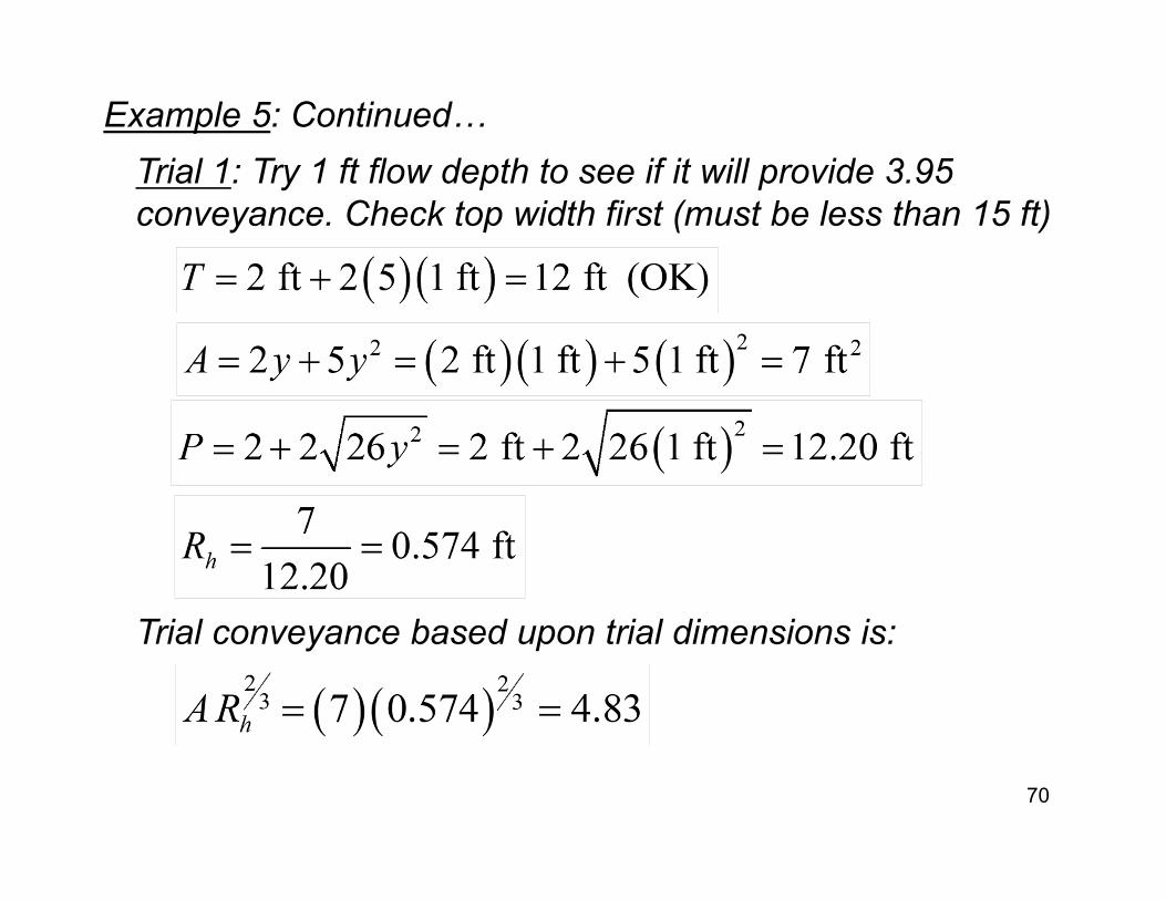
Example 5: Continued…Trial 1: Try 1 ft flow depth to see if it will provide 3.95 conveyance. Check top width first (must be less than 15 ft)
Trial conveyance based upon trial dimensions is:
70
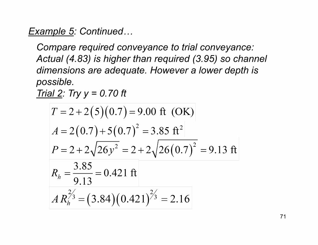
Example 5: Continued…Compare required conveyance to trial conveyance:Actual (4.83) is higher than required (3.95) so channel dimensions are adequate. However a lower depth is possible.Trial 2: Try y = 0.70 ft
71
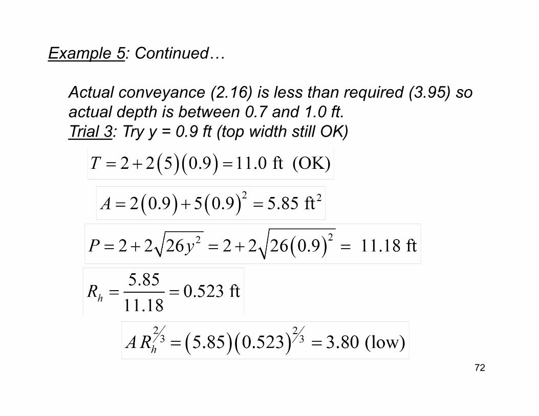
Example 5: Continued…
Actual conveyance (2.16) is less than required (3.95) so actual depth is between 0.7 and 1.0 ft.Trial 3: Try y = 0.9 ft (top width still OK)
72
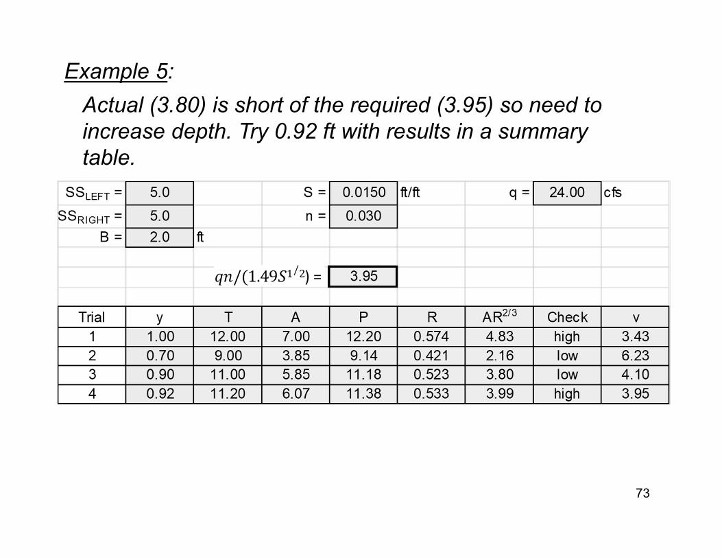
Example 5:
73
Actual (3.80) is short of the required (3.95) so need to increase depth. Try 0.92 ft with results in a summary table.
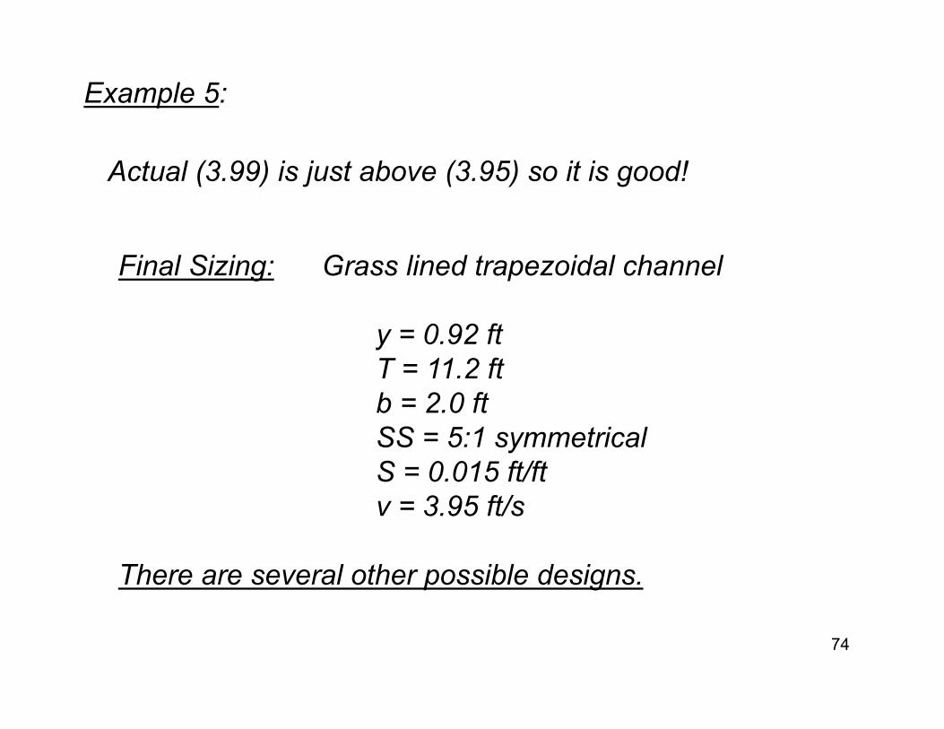
Example 5:
Final Sizing: Grass lined trapezoidal channel
y = 0.92 ft T = 11.2 ft b = 2.0 ftSS = 5:1 symmetricalS = 0.015 ft/ftv = 3.95 ft/s
There are several other possible designs.
74
Actual (3.99) is just above (3.95) so it is good!
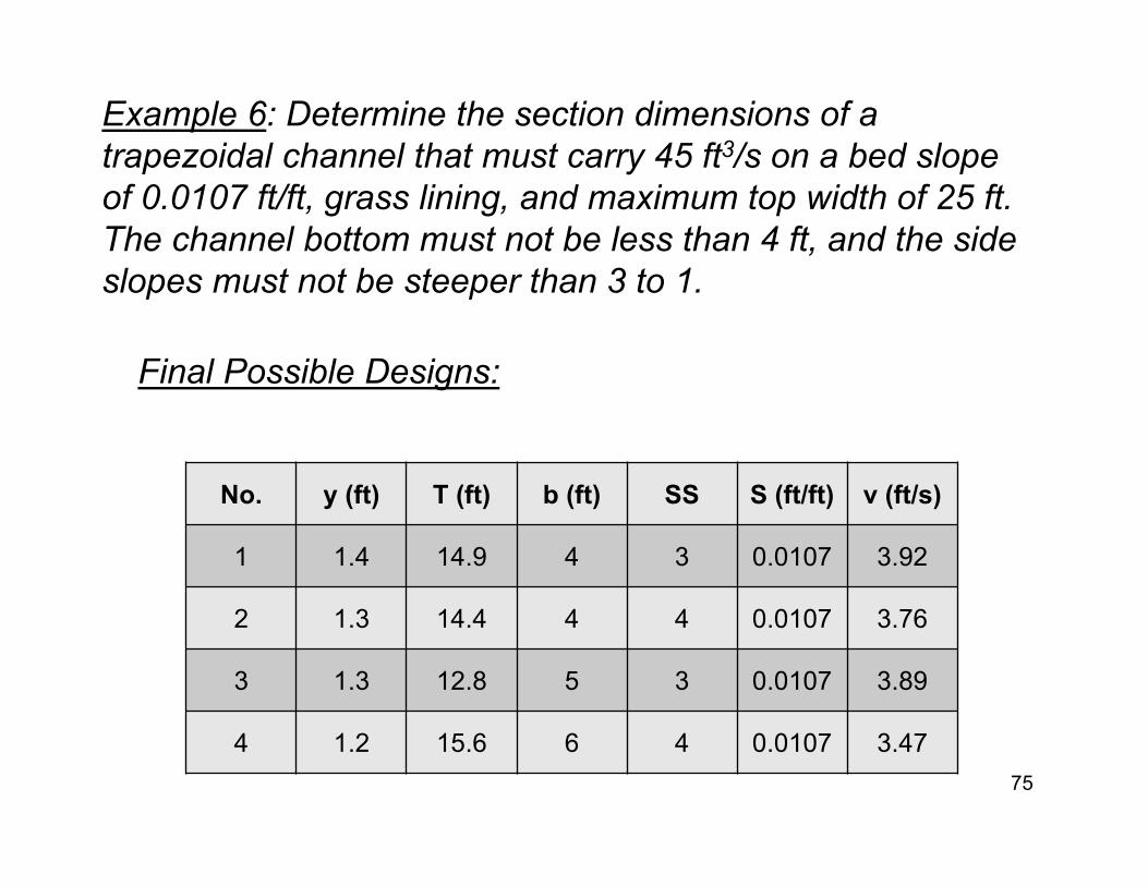
Example 6: Determine the section dimensions of a trapezoidal channel that must carry 45 ft3/s on a bed slope of 0.0107 ft/ft, grass lining, and maximum top width of 25 ft. The channel bottom must not be less than 4 ft, and the side slopes must not be steeper than 3 to 1.
Final Possible Designs:
No. y (ft) T (ft) b (ft) SS S (ft/ft) v (ft/s)
1 1.4 14.9 4 3 0.0107 3.92
2 1.3 14.4 4 4 0.0107 3.76
3 1.3 12.8 5 3 0.0107 3.89
4 1.2 15.6 6 4 0.0107 3.4775
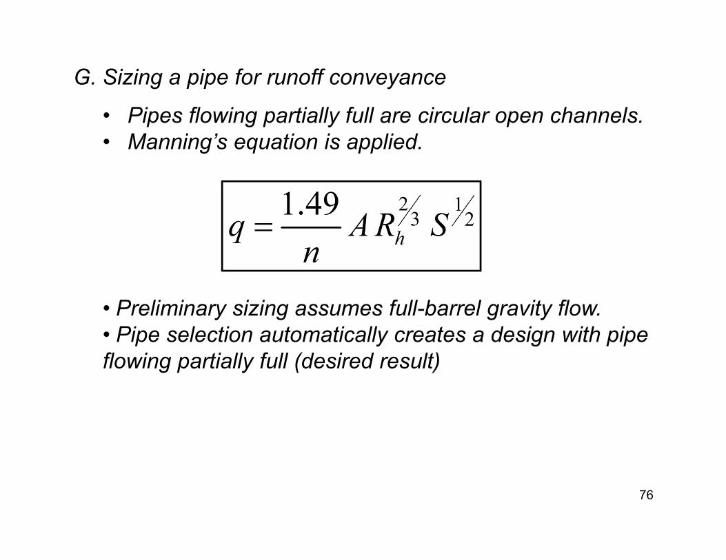
G. Sizing a pipe for runoff conveyance
• Pipes flowing partially full are circular open channels.• Manning’s equation is applied.
• Preliminary sizing assumes full-barrel gravity flow. • Pipe selection automatically creates a design with pipe flowing partially full (desired result)
76
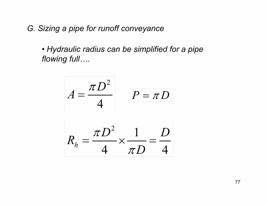
• Hydraulic radius can be simplified for a pipe flowing full….
77
G. Sizing a pipe for runoff conveyance

• Algebraic substitution of A and Rh into Manning’s…
78
G. Sizing a pipe for runoff conveyance
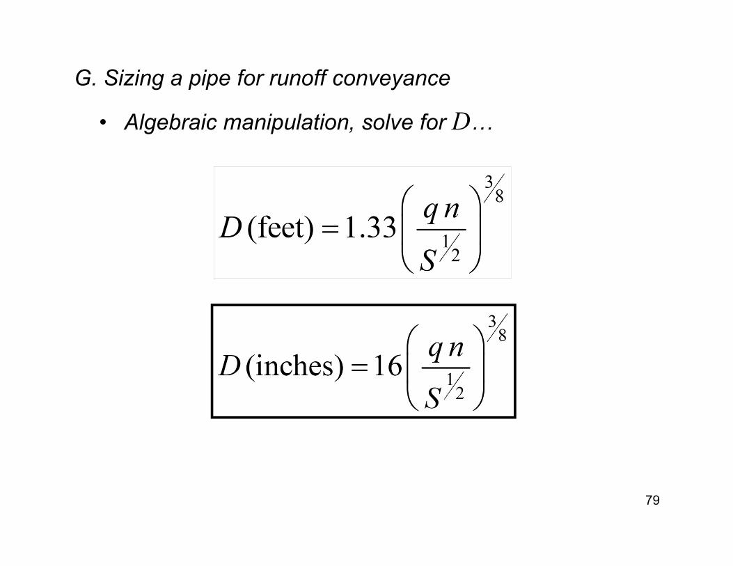
• Algebraic manipulation, solve for D…
79
G. Sizing a pipe for runoff conveyance
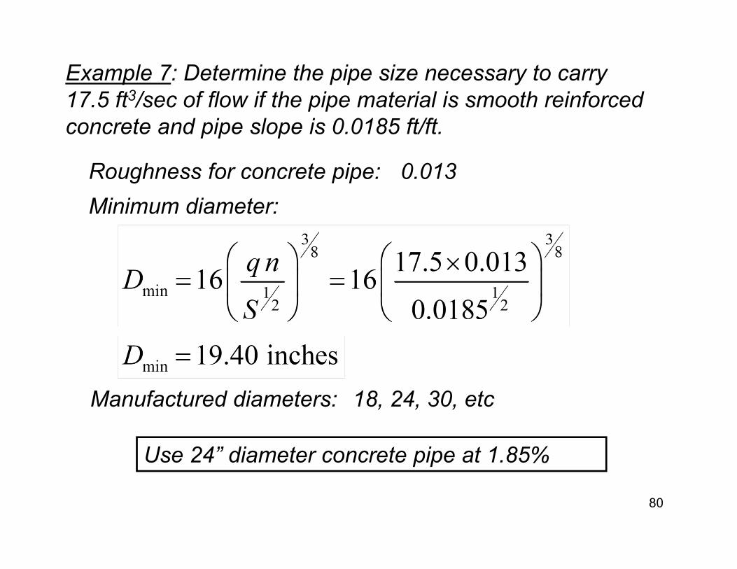
Example 7: Determine the pipe size necessary to carry 17.5 ft3/sec of flow if the pipe material is smooth reinforced concrete and pipe slope is 0.0185 ft/ft.
Roughness for concrete pipe:Minimum diameter:
Use 24” diameter concrete pipe at 1.85%
Manufactured diameters:
0.013
18, 24, 30, etc
80

Example 8: Determine the pipe size necessary to carry 21.8 ft3/s of flow if the pipe material is corrugated metal and pipe slope is 0.0220 ft/ft.
Roughness for CMP:
Minimum diameter:
Use 30” diameter CMP (n=0.024) at 2.20%
0.024 (typical)
81
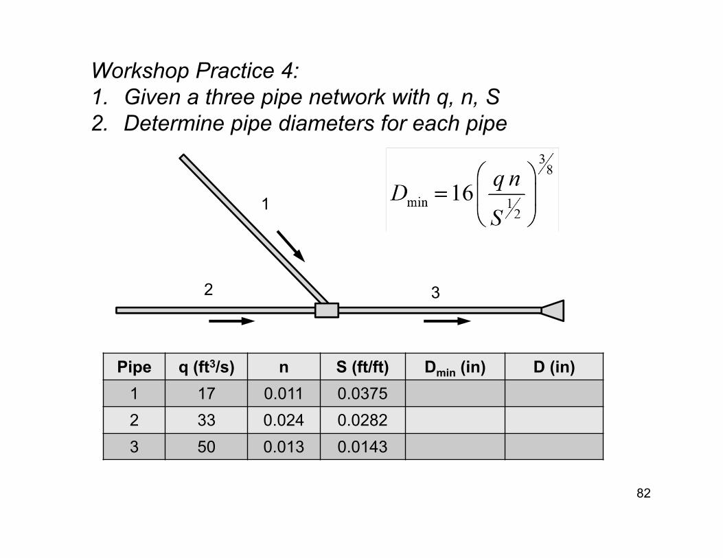
Workshop Practice 4:1. Given a three pipe network with q, n, S2. Determine pipe diameters for each pipe
82
1
32
Pipe q (ft3/s) n S (ft/ft) Dmin (in) D (in)1 17 0.011 0.03752 33 0.024 0.02823 50 0.013 0.0143
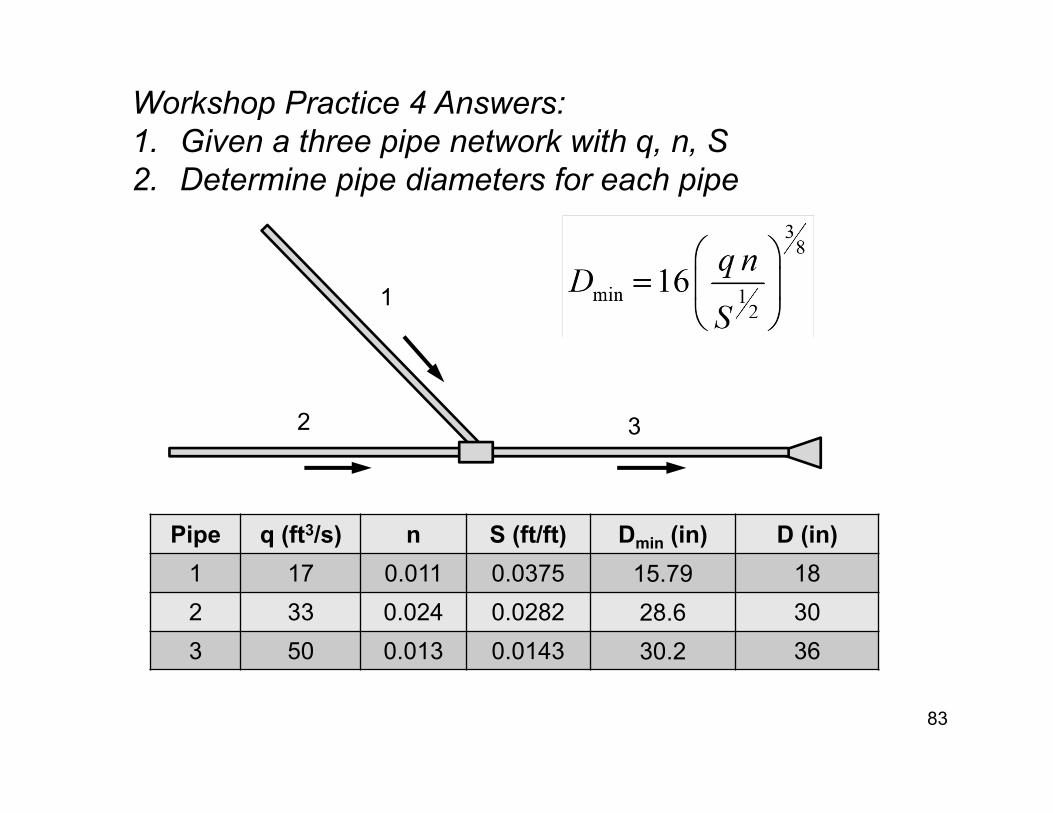
Workshop Practice 4 Answers:1. Given a three pipe network with q, n, S2. Determine pipe diameters for each pipe
83
Pipe q (ft3/s) n S (ft/ft) Dmin (in) D (in)1 17 0.011 0.0375 15.79 182 33 0.024 0.0282 28.6 303 50 0.013 0.0143 30.2 36
1
32
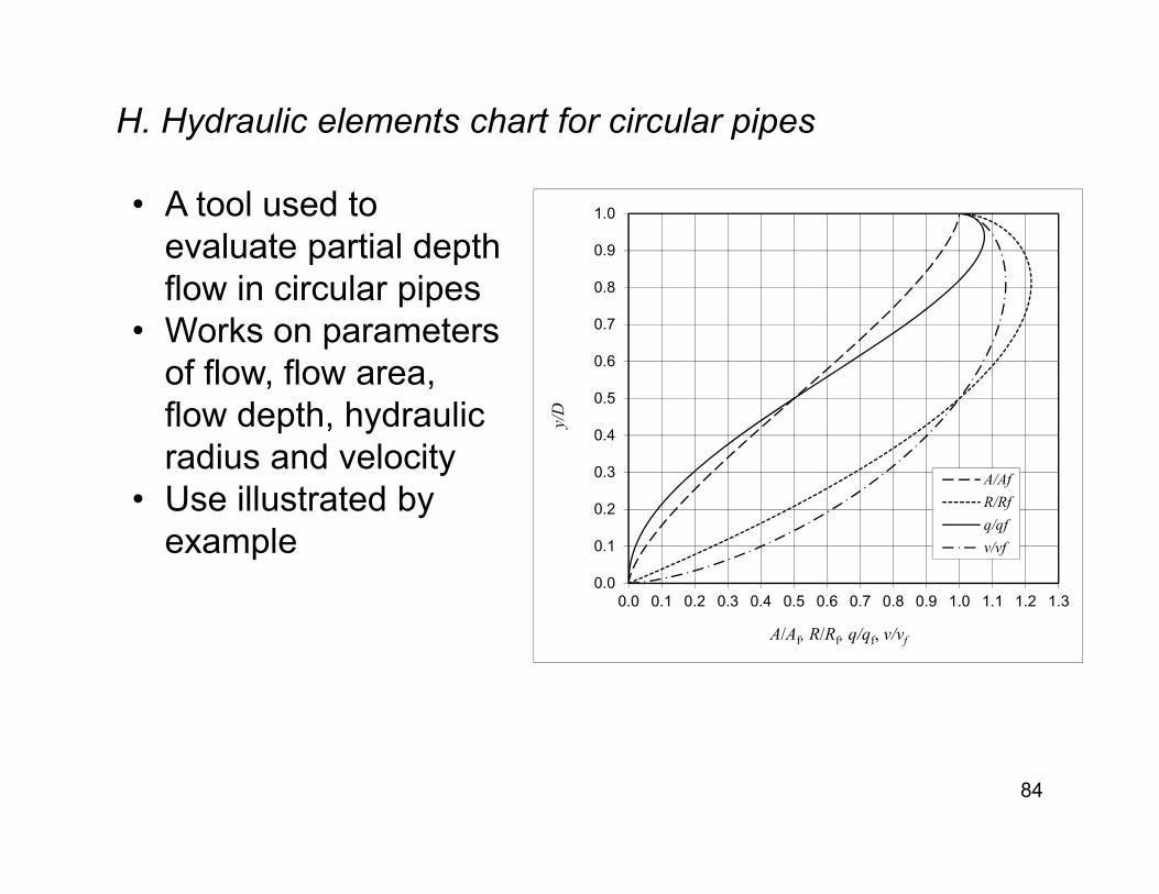
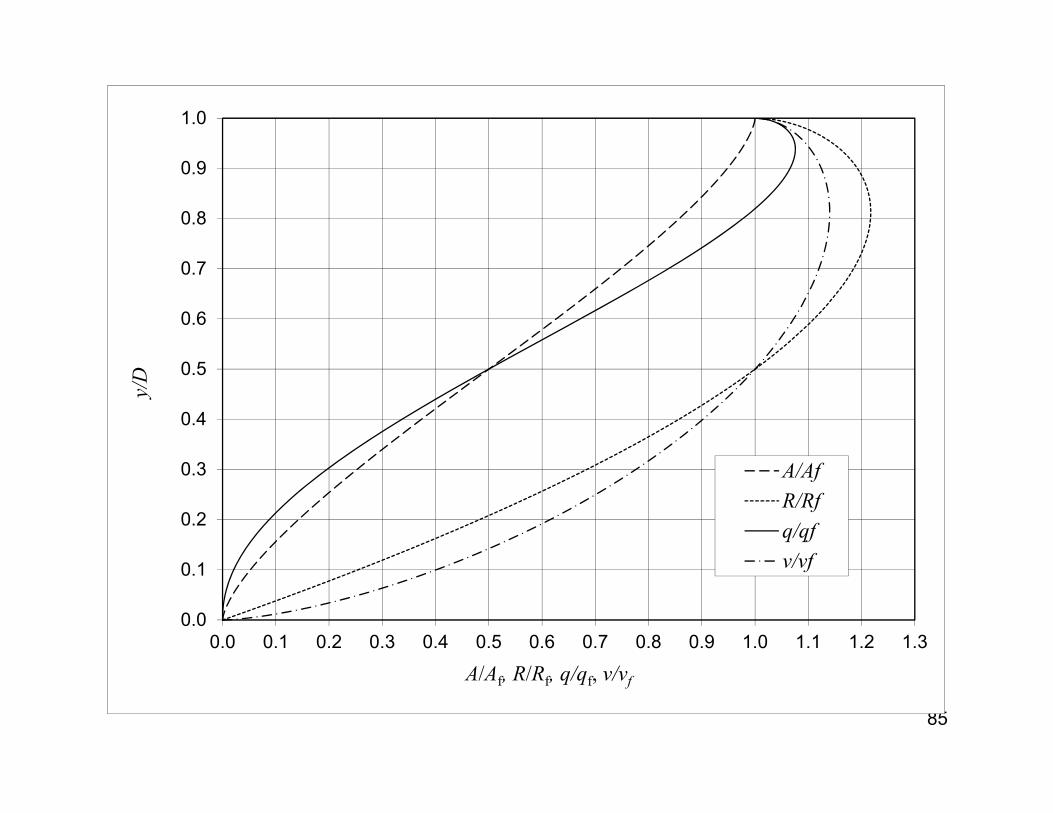
H. Hydraulic elements chart for circular pipes
• A tool used to evaluate partial depth flow in circular pipes
• Works on parameters of flow, flow area, flow depth, hydraulic radius and velocity
• Use illustrated by example
84
0.0
0.1
0.2
0.3
0.4
0.5
0.6
0.7
0.8
0.9
1.0
0.0 0.1 0.2 0.3 0.4 0.5 0.6 0.7 0.8 0.9 1.0 1.1 1.2 1.3
y/D
A/Af, R/Rf, q/qf, v/vf
A/AfR/Rfq/qfv/vf
85
0.0
0.1
0.2
0.3
0.4
0.5
0.6
0.7
0.8
0.9
1.0
0.0 0.1 0.2 0.3 0.4 0.5 0.6 0.7 0.8 0.9 1.0 1.1 1.2 1.3
y/D
A/Af, R/Rf, q/qf, v/vf
A/AfR/Rfq/qfv/vf
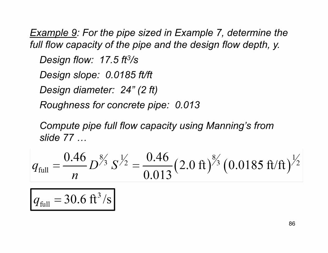
Example 9: For the pipe sized in Example 7, determine the full flow capacity of the pipe and the design flow depth, y.
Roughness for concrete pipe: 0.013
Design slope: 0.0185 ft/ft
86
Design flow: 17.5 ft3/s
Design diameter: 24” (2 ft)
Compute pipe full flow capacity using Manning’s from slide 77 …

Example 9: continued...
87
Compute the ratio qdesign to qfull :
From chart read: y/D = 0.53
Thus:
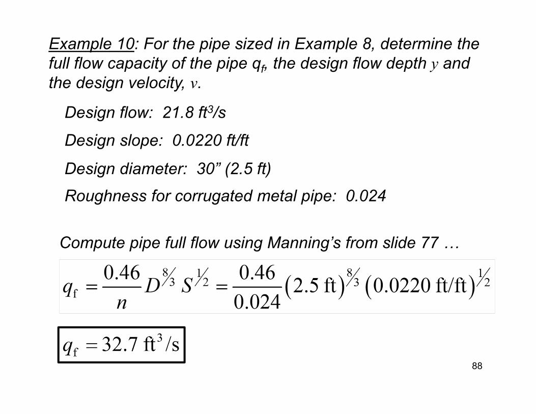
Example 10: For the pipe sized in Example 8, determine the full flow capacity of the pipe qf, the design flow depth y and the design velocity, v.
Roughness for corrugated metal pipe: 0.024
Design slope: 0.0220 ft/ft
88
Design flow: 21.8 ft3/s
Design diameter: 30” (2.5 ft)
Compute pipe full flow using Manning’s from slide 77 …
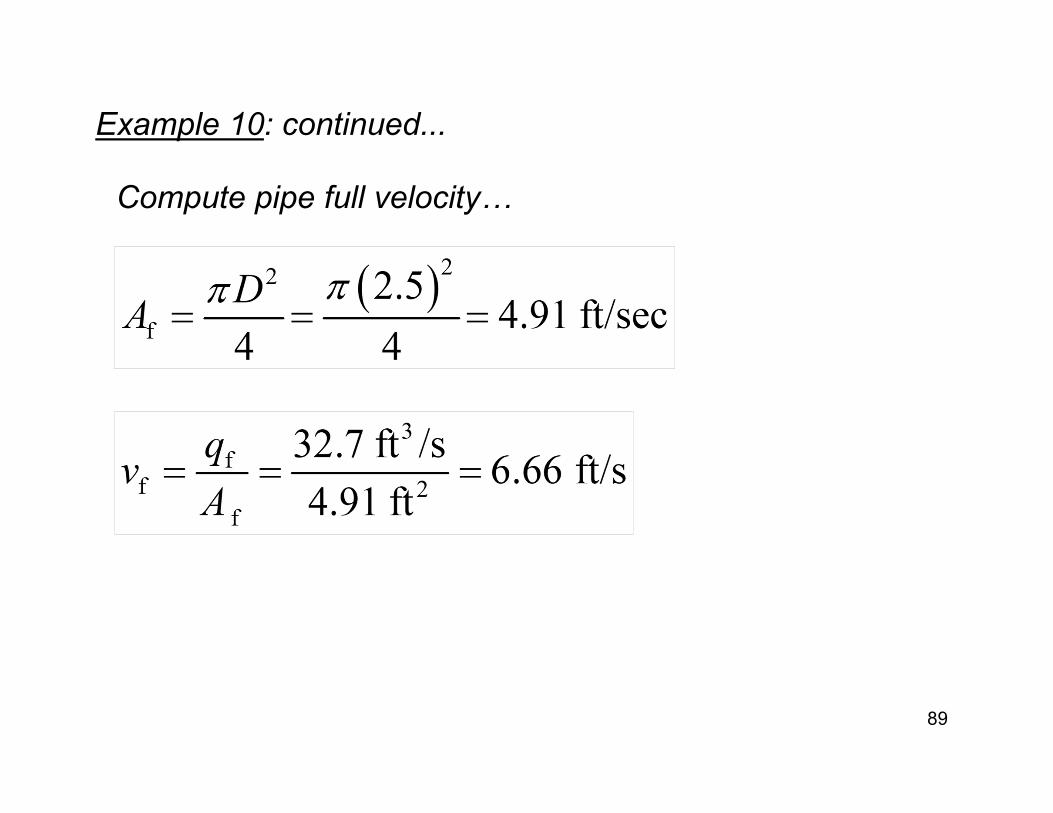
Example 10: continued...
89
Compute pipe full velocity…
Example 10: continued...
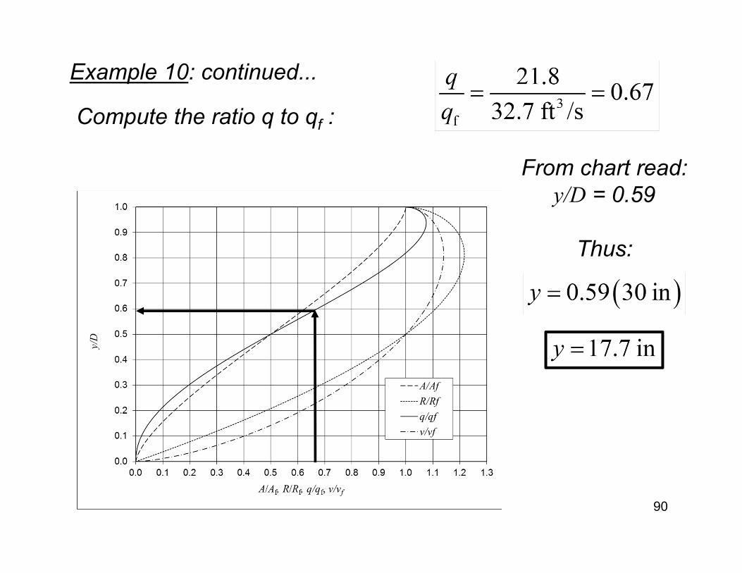
90
Compute the ratio q to qf :
From chart read: y/D = 0.59
Thus:
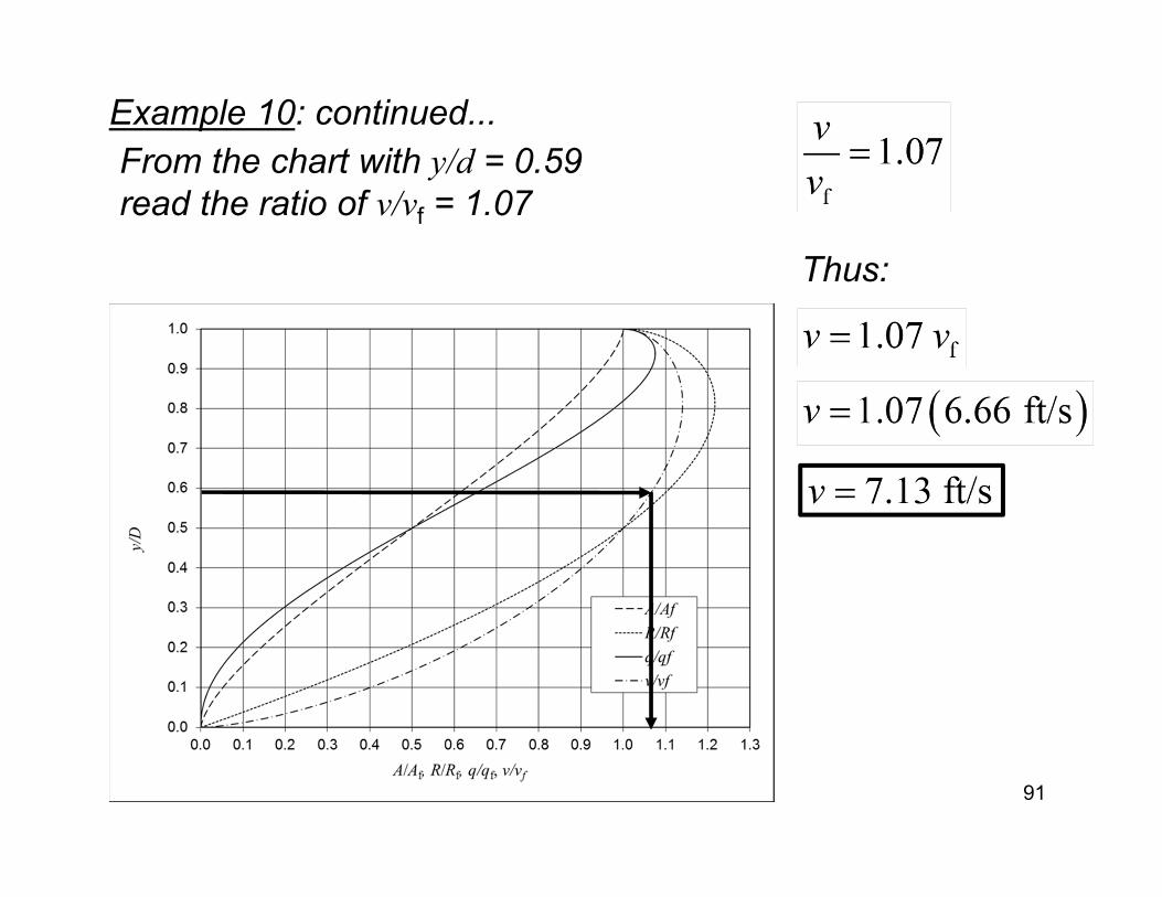
Example 10: continued...
91
From the chart with y/d = 0.59 read the ratio of v/vf = 1.07
Thus:
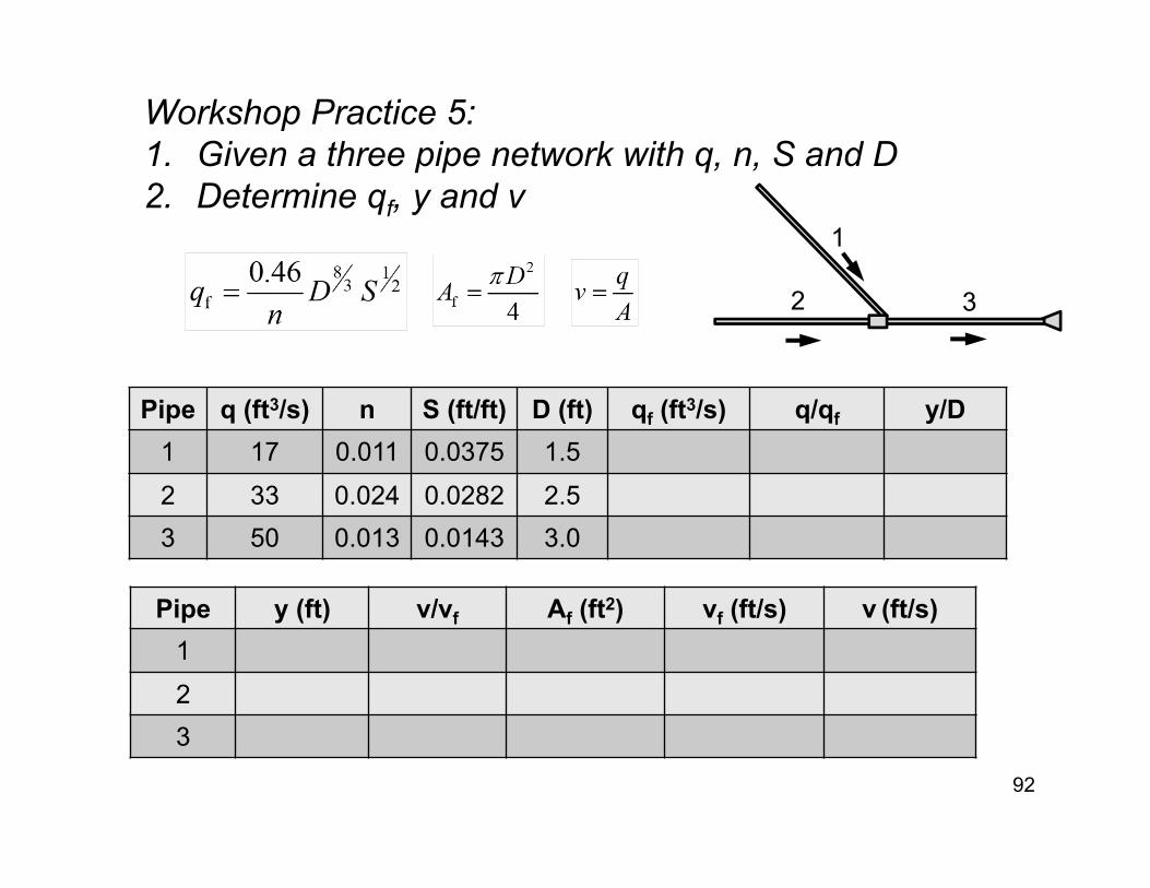
Workshop Practice 5:1. Given a three pipe network with q, n, S and D2. Determine qf, y and v
92
Pipe q (ft3/s) n S (ft/ft) D (ft) qf (ft3/s) q/qf y/D1 17 0.011 0.0375 1.52 33 0.024 0.0282 2.53 50 0.013 0.0143 3.0
1
32
Pipe y (ft) v/vf Af (ft2) vf (ft/s) v (ft/s)123
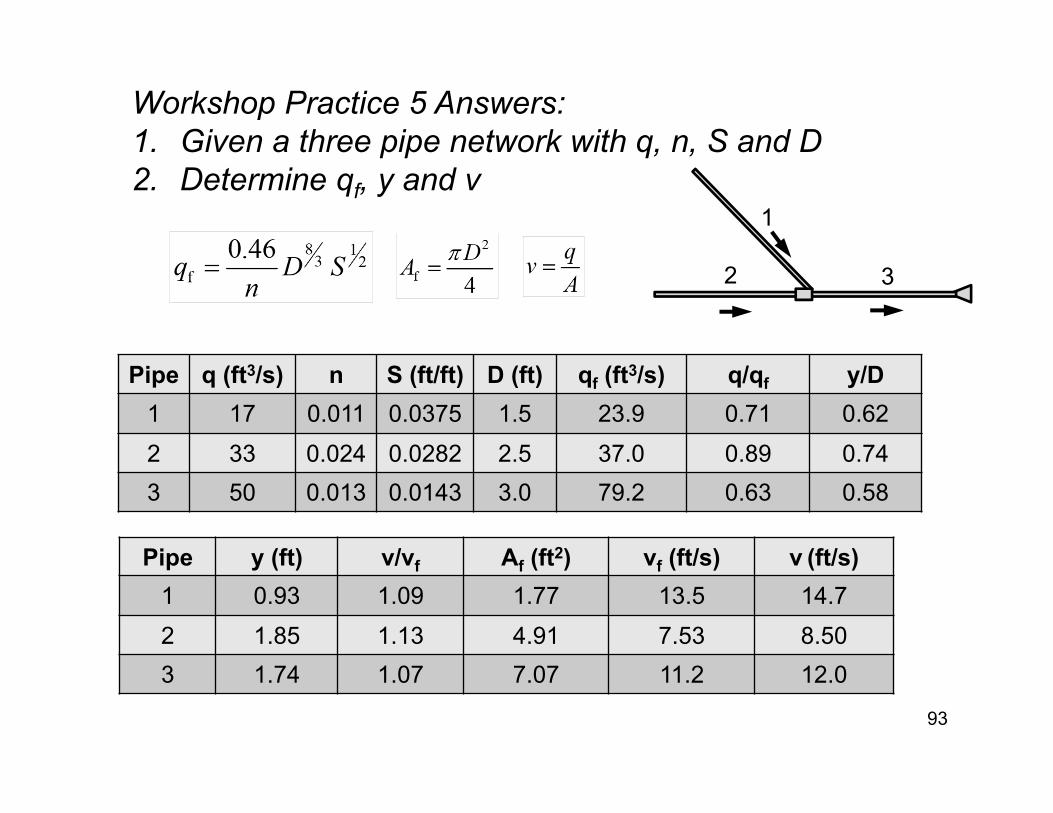
Workshop Practice 5 Answers:1. Given a three pipe network with q, n, S and D2. Determine qf, y and v
93
Pipe q (ft3/s) n S (ft/ft) D (ft) qf (ft3/s) q/qf y/D1 17 0.011 0.0375 1.5 23.9 0.71 0.622 33 0.024 0.0282 2.5 37.0 0.89 0.743 50 0.013 0.0143 3.0 79.2 0.63 0.58
1
32
Pipe y (ft) v/vf Af (ft2) vf (ft/s) v (ft/s)1 0.93 1.09 1.77 13.5 14.72 1.85 1.13 4.91 7.53 8.503 1.74 1.07 7.07 11.2 12.0
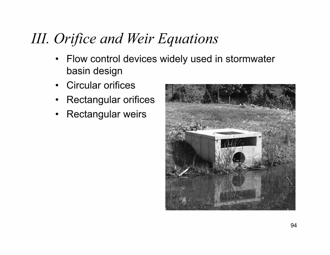
III. Orifice and Weir Equations
94
• Flow control devices widely used in stormwaterbasin design
• Circular orifices• Rectangular orifices• Rectangular weirs
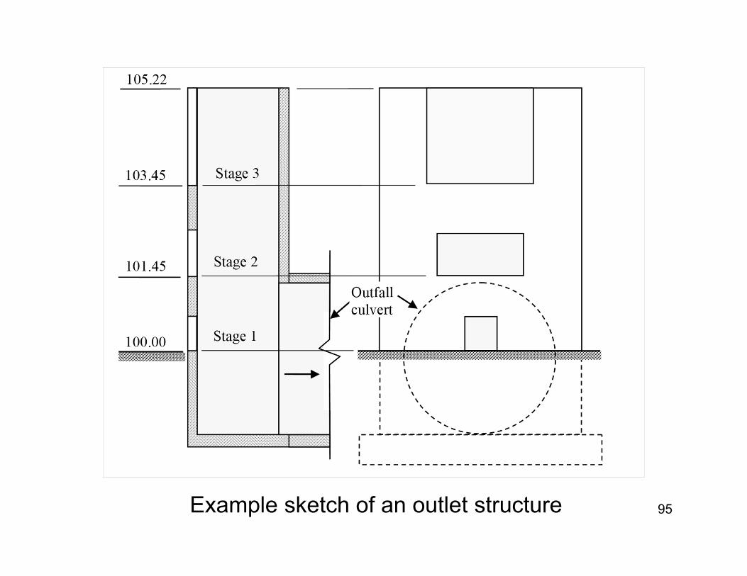
95Example sketch of an outlet structure
96
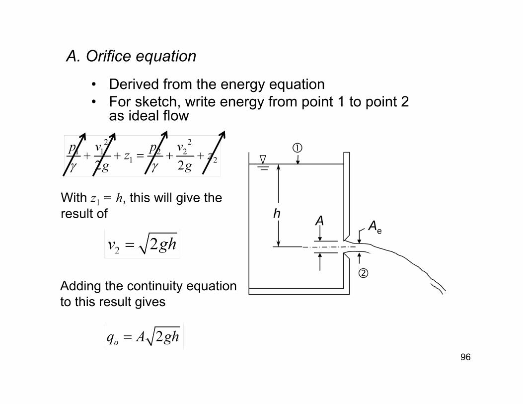
A. Orifice equation
• Derived from the energy equation • For sketch, write energy from point 1 to point 2
as ideal flow
With z1 = h, this will give the result of
Adding the continuity equation to this result gives
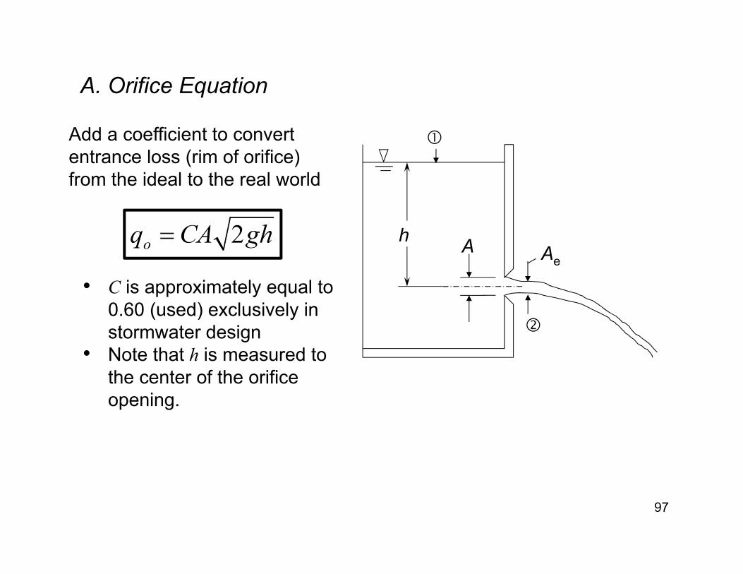
A. Orifice Equation
97
A Ae
h
• C is approximately equal to 0.60 (used) exclusively in stormwater design
• Note that h is measured to the center of the orifice opening.
Add a coefficient to convert entrance loss (rim of orifice) from the ideal to the real world
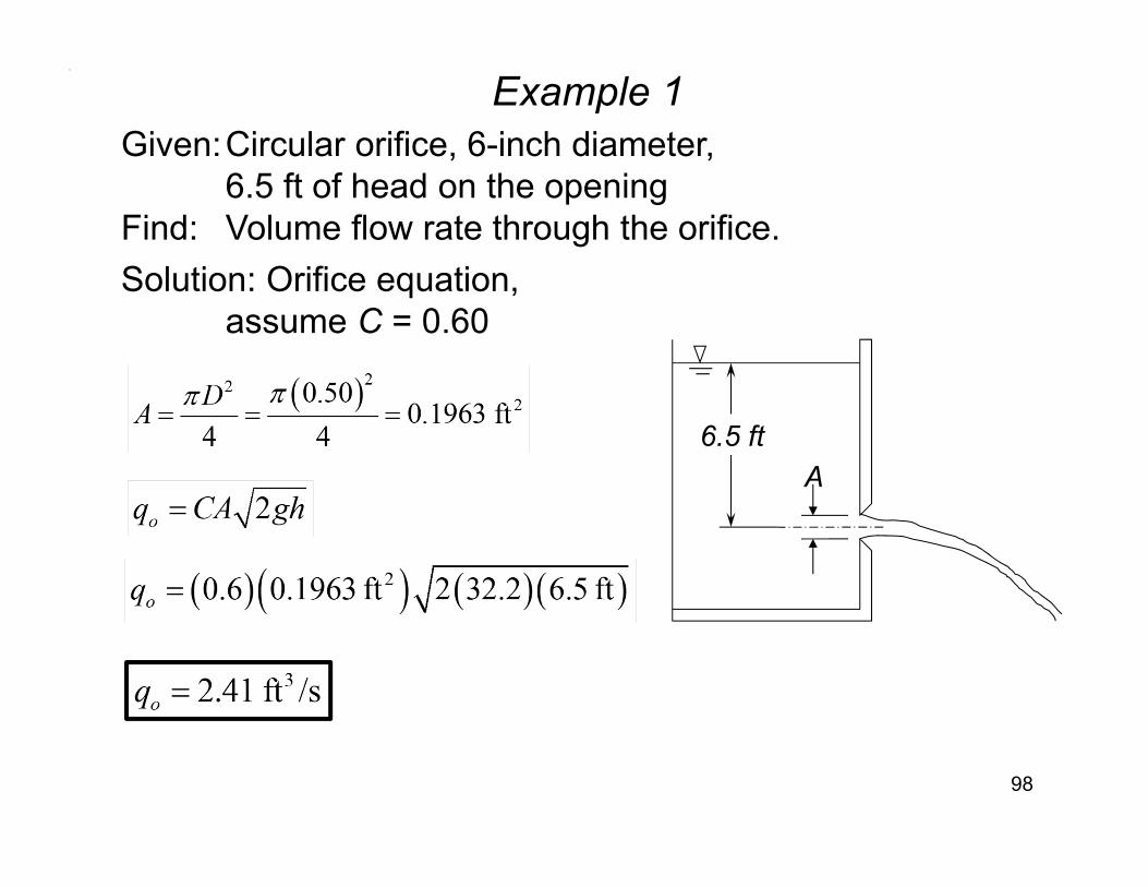
Example 1
98
Given:Circular orifice, 6-inch diameter, 6.5 ft of head on the opening
Find: Volume flow rate through the orifice.Solution: Orifice equation,
assume C = 0.60
A6.5 ft
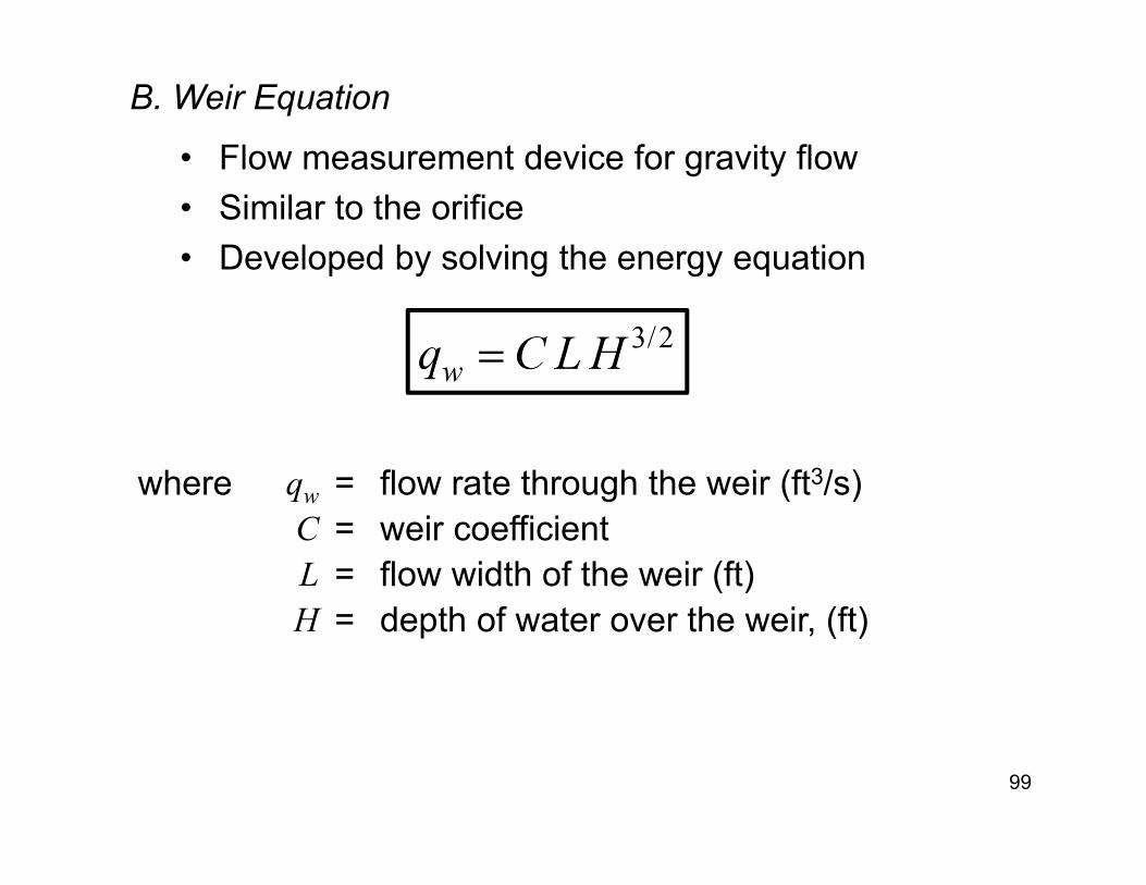
B. Weir Equation
99
• Flow measurement device for gravity flow• Similar to the orifice• Developed by solving the energy equation
where qw = flow rate through the weir (ft3/s)C = weir coefficient L = flow width of the weir (ft)H = depth of water over the weir, (ft)
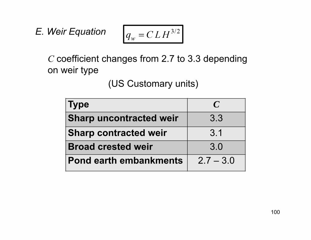
E. Weir Equation
100
C coefficient changes from 2.7 to 3.3 depending on weir type
(US Customary units)
Type CSharp uncontracted weir 3.3Sharp contracted weir 3.1Broad crested weir 3.0Pond earth embankments 2.7 – 3.0
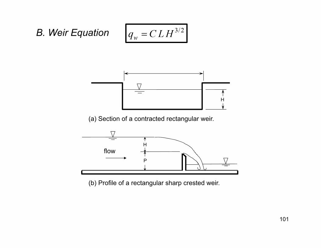
B. Weir Equation
101
flowP
H
H
(a) Section of a contracted rectangular weir.
(b) Profile of a rectangular sharp crested weir.
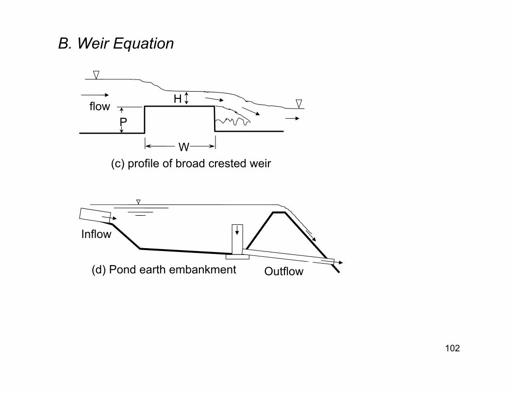
B. Weir Equation
102
flow P
H
W(c) profile of broad crested weir
(d) Pond earth embankment
Inflow
Outflow
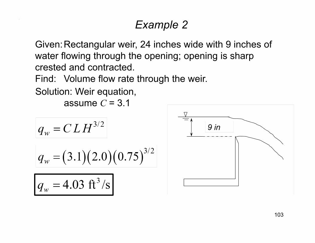
Example 2
103
Given:Rectangular weir, 24 inches wide with 9 inches of water flowing through the opening; opening is sharp crested and contracted.Find: Volume flow rate through the weir.Solution: Weir equation,
assume C = 3.1
9 in
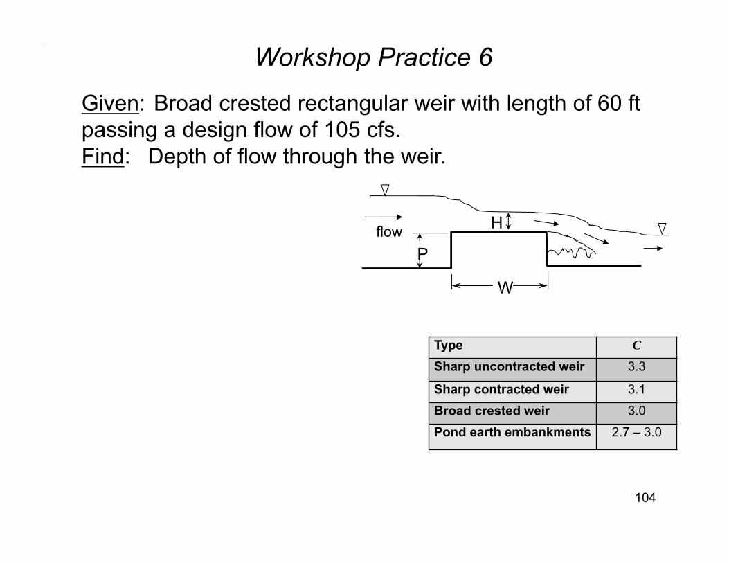
Workshop Practice 6
104
Given: Broad crested rectangular weir with length of 60 ftpassing a design flow of 105 cfs.Find: Depth of flow through the weir.
Type C
Sharp uncontracted weir 3.3
Sharp contracted weir 3.1Broad crested weir 3.0Pond earth embankments 2.7 – 3.0
flow P
H
W
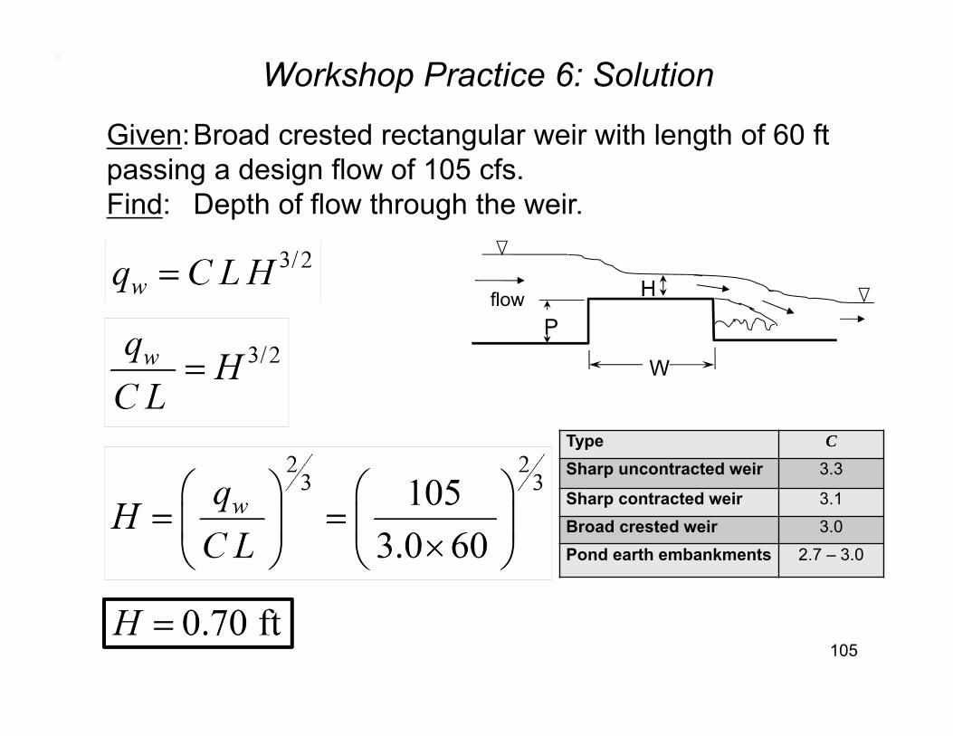
Workshop Practice 6: Solution
105
Given:Broad crested rectangular weir with length of 60 ftpassing a design flow of 105 cfs.Find: Depth of flow through the weir.
flow P
H
W
Type C
Sharp uncontracted weir 3.3
Sharp contracted weir 3.1Broad crested weir 3.0Pond earth embankments 2.7 – 3.0
Example 3
106
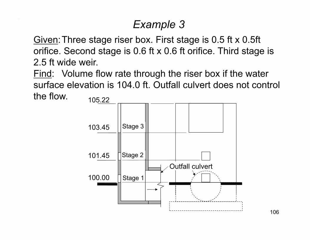
Given:Three stage riser box. First stage is 0.5 ft x 0.5ft orifice. Second stage is 0.6 ft x 0.6 ft orifice. Third stage is 2.5 ft wide weir.Find: Volume flow rate through the riser box if the water surface elevation is 104.0 ft. Outfall culvert does not control the flow.
100.00
103.45
105.22
101.45 Stage 2
Stage 1
Stage 3
Outfall culvert
Example 3 (continued)
107
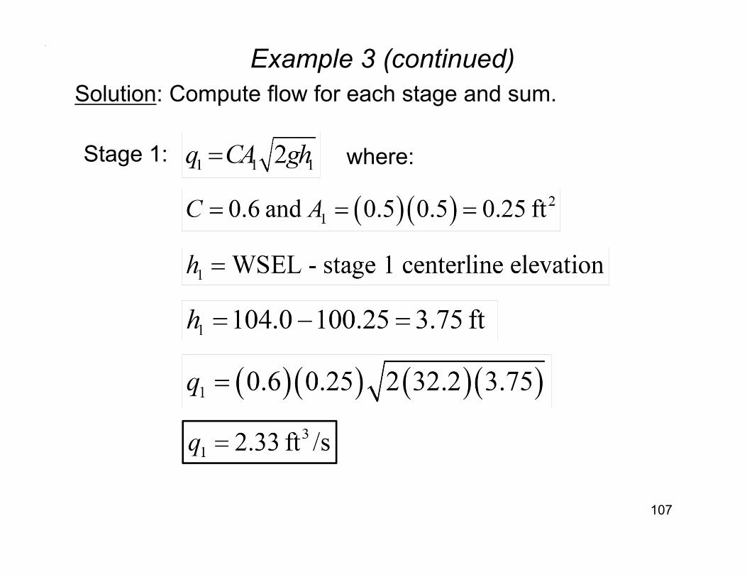
Solution: Compute flow for each stage and sum.
Stage 1: where:
Example 3 (continued)
108
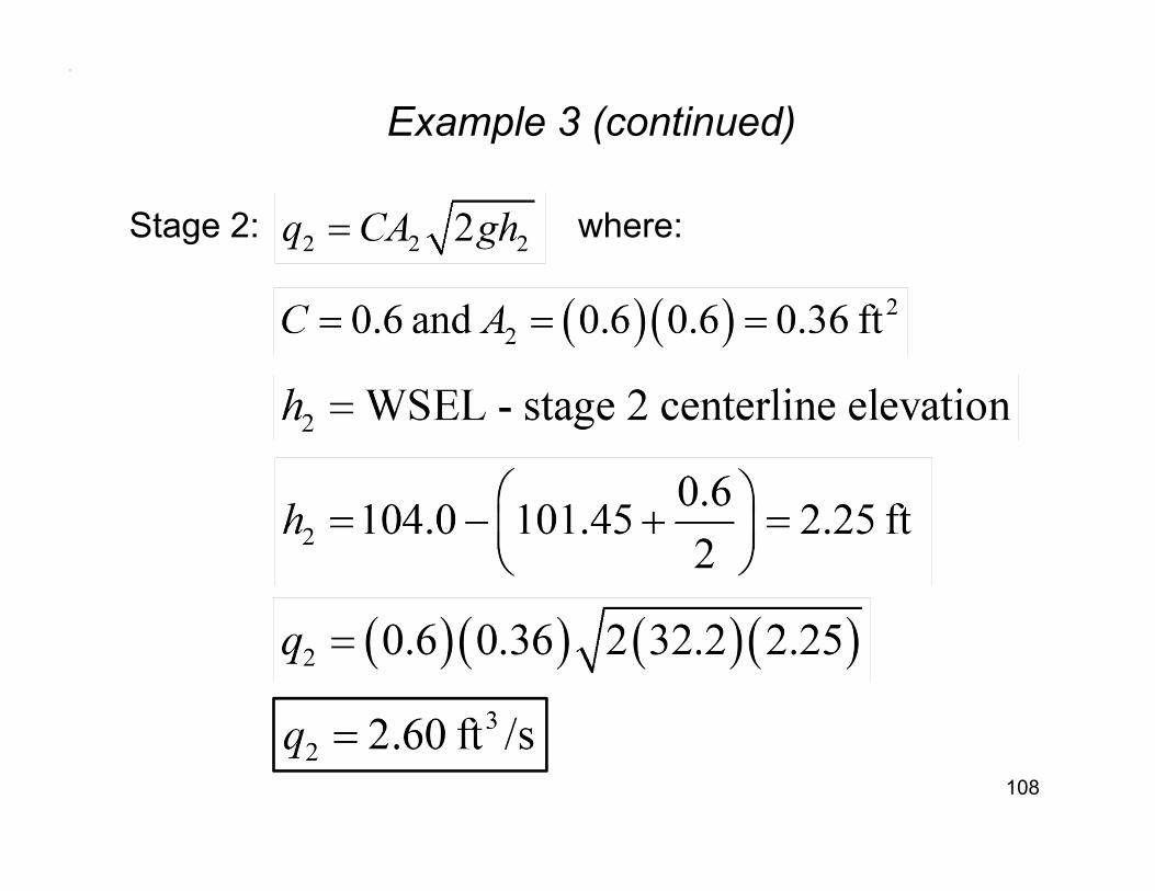
Stage 2: where:

Example 3 (continued)
109
Stage 3: where:
Example 3 (continued)
110
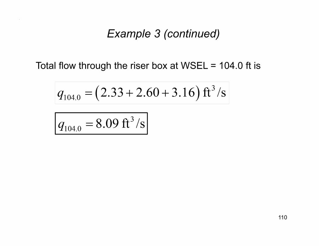
Total flow through the riser box at WSEL = 104.0 ft is

Workshop Practice 7
111
Given:Three stage riser box. First stage is 0.5 ft x 0.5ft orifice. Second stage is 0.6 ft x 0.6 ft orifice. Third stage is 2.5 ft wide weir.Find: Volume flow rate through the riser box if the water surface elevation is 105.0 ft. Outfall culvert does not control the flow.
100.00
103.45
105.22
101.45 Stage 2
Stage 1
Stage 3
Outfall culvert
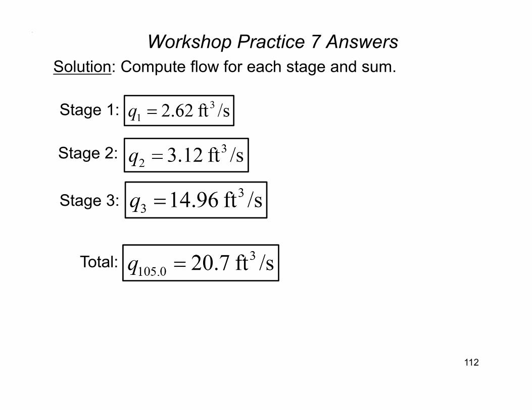
Workshop Practice 7 Answers
112
Solution: Compute flow for each stage and sum.
Stage 1:
Stage 2:
Stage 3:
Total:
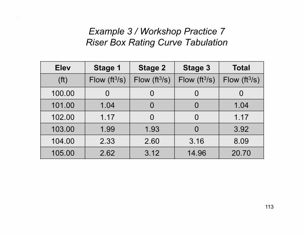
Example 3 / Workshop Practice 7 Riser Box Rating Curve Tabulation
113
Elev Stage 1 Stage 2 Stage 3 Total(ft) Flow (ft3/s) Flow (ft3/s) Flow (ft3/s) Flow (ft3/s)
100.00 0 0 0 0101.00 1.04 0 0 1.04102.00 1.17 0 0 1.17103.00 1.99 1.93 0 3.92104.00 2.33 2.60 3.16 8.09105.00 2.62 3.12 14.96 20.70
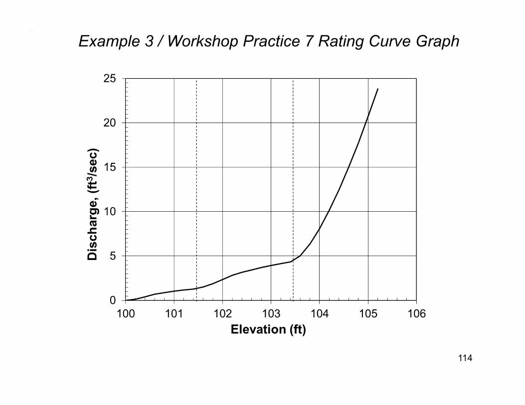
Example 3 / Workshop Practice 7 Rating Curve Graph
114
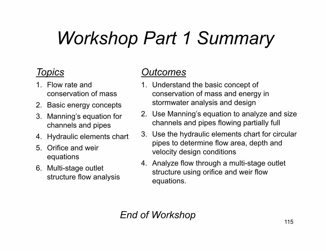
Topics 1. Flow rate and
conservation of mass2. Basic energy concepts3. Manning’s equation for
channels and pipes4. Hydraulic elements chart5. Orifice and weir
equations6. Multi-stage outlet
structure flow analysis
Workshop Part 1 Summary
Outcomes1. Understand the basic concept of
conservation of mass and energy in stormwater analysis and design
2. Use Manning’s equation to analyze and size channels and pipes flowing partially full
3. Use the hydraulic elements chart for circular pipes to determine flow area, depth and velocity design conditions
4. Analyze flow through a multi-stage outlet structure using orifice and weir flow equations.
End of Workshop115