Embed Size (px)
Citation preview
Updated 1 March 2012
tomoRecon: High-speed tomography reconstruction on workstations using multi-threading
Mark L. Rivers*a
aCenter for Advanced Radiation Sources, University of Chicago, 9700 South Cass Avenue, Argonne, IL 60647
ABSTRACT
Computers have changed remarkably in just the last 2-3 years. Memory is now very inexpensive, as little as $10/GB, or less than $1000 for 96GB. Computers with 8 or 12 cores are now inexpensive, starting at less than $3,000. This means that affordable workstations are in principle now capable of processing large tomography datasets. But for the most part tomography reconstruction software has not changed to take advantage of these new capabilities. Most installations use clusters of Linux machines, spreading the work over computers running multiple processes. It is significantly simpler and cheaper to run a single process that spreads the job over multiple threads running on multiple cores. tomoRecon is a new multi-threaded library for such tomography data reconstruction. It consists of only 545 lines of C++ code, on top of the ~800 lines in the Gridrec reconstruction code. The performance using tomoRecon on a single modern workstation significantly exceeds dedicated clusters currently in use at synchrotron beamlines.
Keywords: tomography, reconstruction, parallel computing, Gridrec, multi-threading
1. INTRODUCTION
Computers have changed remarkably in just the last 2-3 years. Memory is now very inexpensive, as little as $10/GB, or less than $1000 for 96GB. Computers with 8 or 12 cores are now inexpensive, starting at less than $3,000. This means that affordable workstations are in principle now capable of processing large tomography datasets. But for the most part tomography reconstruction software has not changed to take advantage of these new capabilities. Most dedicated synchrotron tomography beamlines use clusters of Linux machines, spreading the work over computers running multiple processes. It would be significantly simpler and cheaper to run a single process that spreads the job over multiple threads running on multiple cores.
The time to collect high-resolution tomographic datasets has also decreased rapidly in the last several years. This is largely due to the introduction of high-speed CMOS cameras that can collect thousands of frames per second. Examples include the PCO Dimax camera which is in use, for example, at beamline 2-BM at the APS and at the TOMCAT beamline at the Swiss Light Source. This camera can collect 1279 frames/second at 2016 x 2016 resolution. Using white or pink beam from a synchrotron it is thus now possible to collect an entire [2016, 2016, 1200] dataset in 1 second. (In this paper the dimensions of input projection data are given as [NX, NY, NZ] where NX is the number of pixels perpendicular to the rotation axis, NY is the number of pixels (slices) parallel to the rotation axis, and NZ is the number of projections. After reconstruction the dimensions are [NX, NX, NY].) It does require several minutes to read the data from the camera, but clearly there is an increased need for rapid reconstruction to keep up with the rate at which data is being collected with these new detectors.
1.1 Goals for reconstruction
When collecting tomography data one highly desirable goal is to be able to reconstruct the data in less time than it takes to collect. It is then possible to examine the previous data set even before the next one is complete, allowing rapid feedback on data quality and experimental conditions. It also prevents a backlog of data to be reconstructed when the collection is complete. With the high-speed acquisition now possible improvements in reconstruction speed would clearly be welcome.
At synchrotron beamlines typically the data is reconstructed at the facility during the user’s visit, and the users take reconstructed data home with them. However, there are many cases when it would also be very useful for the users to be
able to reconstruct the data at their home institutions. For example, they may want to change the reconstruction parameters, such as the rotation center, ring artifact removal, etc. because the values used at the facility were not optimal. It would thus be very useful to be able reconstruct even large datasets in reasonable time on computers that users are likely to have available to them locally.
1.2 Reconstruction times at existing facilities
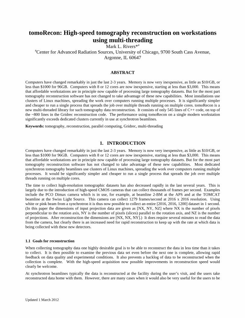
Table 1 lists the reconstruction computing infrastructure and some typical reconstruction times for a number of synchrotron beamlines. These times including the file I/O times for reading the input data and writing the reconstructed output to disk.
Table 1. Reconstruction hardware, software, and reconstruction times at some synchrotron microtomography beamlines.
Beamline Computer Cost Software Medium dataset Large dataset
(~) Size Time (s) Size Time (s)
APS 2-BM1 8-node Linux cluster
$70,000 Gridrec [1392, 1040, 900]
441 [2048, 2048, 1500]
2642
Swiss Light Source TOMCAT2
5-node Linux cluster
$50,000 Gridrec [1024, 1024, 1001]
1 job: 1674 20 jobs: 119
[2048, 2048, 1501]
1 job: 7651 20 jobs: 473
ALS 8.3.23 Windows 7 64-bit workstation
$7,000 Octopus + FIJI
[1024, 1024, 1024
no GPU 310 w/ GPU 105
[2048, 2048, 1024]
No GPU 1300 w/GPU 479
APS 13-BM Windows 7 64-bit workstation
$6,000 Gridrec + IDL
[1392, 1040, 900]
282 [2048, 2048, 1500]
996
It can be seen from Table 1 that even with rather large and expensive computer clusters the time to reconstruct 2K x 2K datasets requires between 6 and 44 minutes.
2. SOFTWARE ARCHTECTURE
2.1 Overview
Many synchrotron beamlines now use the Gridrec software4,5,6 for the tomography reconstruction. Gridrec is very fast for reconstructing parallel beam tomography data. It is based on Fast Fourier Transforms, but uses an innovative gridding technique to produce high-quality reconstructions that are very close to conventional filtered backprojection6.
The new software package described in this paper is called tomoRecon. It uses Gridrec as the underlying reconstruction engine. However, it reconstructs multiple slices simultaneously using multiple threads. Each thread can be running on its own core. Everything runs in a single computer process, which significantly reduces the overhead and complexity of parallel execution compared to multiple processes running on one or more machines.
2.2 Multi-threaded software needs
In order to implement a multithreaded application like tomoRecon it is necessary to have a support library that provides the following:
Support for creating and operating on threads
Support for mutexes to prevent conflicts when threads need to access shared data
Support for a message passing system for passing data between threads
Support for events for signaling between threads
Support for date and time operations
To make such an application portable across multiple operating systems it is very helpful if this library is written to operate identically on several operating systems.
2.3 EPICS libCom
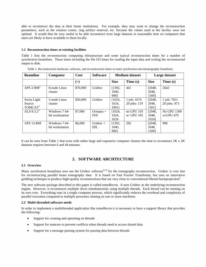
For this project I have used the libCom library from the EPICS7 control system, which provides an operating system independent implementation of all of the required tools listed above. libCom operates transparently on the most commonly used workstation operating systems (Linux, Windows and Mac OSX) as well a number of real-time operating systems (vxWorks, RTEMS). Table 2 lists the EPICS Application Programming Interfaces (APIs) and functions used in tomoRecon.
Table 2. EPICS APIs and functions used for multi-threading support in tomoRecon.
EPICS API Functions used
epicsThread epicsThreadCreate, epicsThreadGetNameSelf
epicsMessageQueue epicsMessageQueueCreate, epicsMessageQueueTrySend, epicsMessageQueueTryReceive, epicsMessageQueueReceive, epicsMessageQueueDestroy
epicsEvent epicsEventCreate, epicsEventSignal, epicsEventWait, epicsEventDestroy
epicsMutex epicsMutexCreate, epicsMutexLock, epicsMutexUnlock, epicsMutexDestroy
epicsTime epicsTimeGetCurrent, epicsTimeDiffInSeconds, epicsTimeToStrftime
2.4 tomoRecon
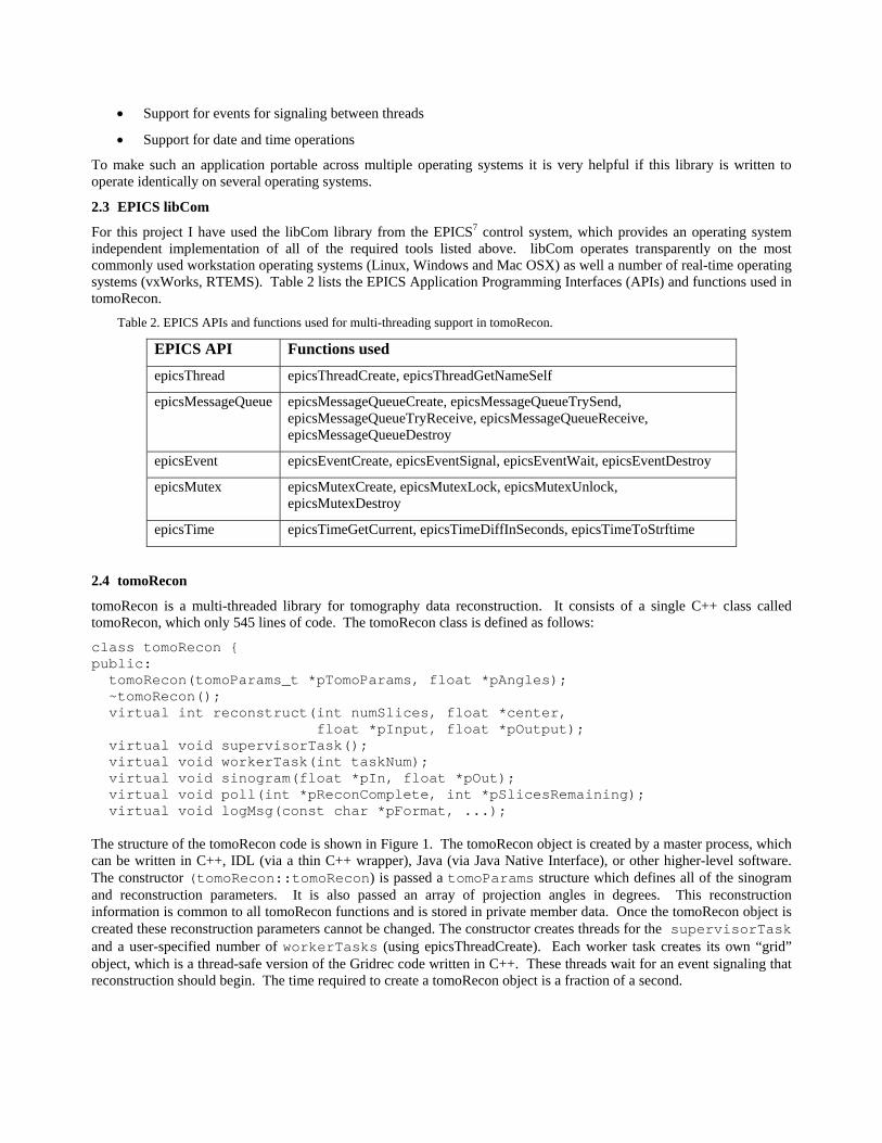
tomoRecon is a multi-threaded library for tomography data reconstruction. It consists of a single C++ class called tomoRecon, which only 545 lines of code. The tomoRecon class is defined as follows:
class tomoRecon { public: tomoRecon(tomoParams_t *pTomoParams, float *pAngles); ~tomoRecon(); virtual int reconstruct(int numSlices, float *center, float *pInput, float *pOutput); virtual void supervisorTask(); virtual void workerTask(int taskNum); virtual void sinogram(float *pIn, float *pOut); virtual void poll(int *pReconComplete, int *pSlicesRemaining); virtual void logMsg(const char *pFormat, ...); The structure of the tomoRecon code is shown in Figure 1. The tomoRecon object is created by a master process, which can be written in C++, IDL (via a thin C++ wrapper), Java (via Java Native Interface), or other higher-level software. The constructor (tomoRecon::tomoRecon) is passed a tomoParams structure which defines all of the sinogram and reconstruction parameters. It is also passed an array of projection angles in degrees. This reconstruction information is common to all tomoRecon functions and is stored in private member data. Once the tomoRecon object is created these reconstruction parameters cannot be changed. The constructor creates threads for the supervisorTask and a user-specified number of workerTasks (using epicsThreadCreate). Each worker task creates its own “grid” object, which is a thread-safe version of the Gridrec code written in C++. These threads wait for an event signaling that reconstruction should begin. The time required to create a tomoRecon object is a fraction of a second.
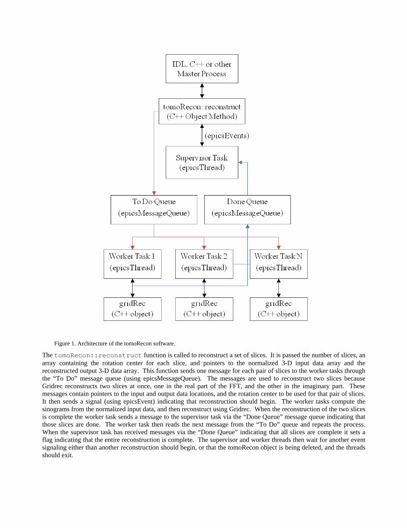
Figure 1. Architecture of the tomoRecon software.
The tomoRecon::reconstruct function is called to reconstruct a set of slices. It is passed the number of slices, an array containing the rotation center for each slice, and pointers to the normalized 3-D input data array and the reconstructed output 3-D data array. This function sends one message for each pair of slices to the worker tasks through the “To Do” message queue (using epicsMessageQueue). The messages are used to reconstruct two slices because Gridrec reconstructs two slices at once, one in the real part of the FFT, and the other in the imaginary part. These messages contain pointers to the input and output data locations, and the rotation center to be used for that pair of slices. It then sends a signal (using epicsEvent) indicating that reconstruction should begin. The worker tasks compute the sinograms from the normalized input data, and then reconstruct using Gridrec. When the reconstruction of the two slices is complete the worker task sends a message to the supervisor task via the “Done Queue” message queue indicating that those slices are done. The worker task then reads the next message from the “To Do” queue and repeats the process. When the supervisor task has received messages via the “Done Queue” indicating that all slices are complete it sets a flag indicating that the entire reconstruction is complete. The supervisor and worker threads then wait for another event signaling either than another reconstruction should begin, or that the tomoRecon object is being deleted, and the threads should exit.
The tomoRecon::sinogram function computes a sinogram from normalized input data. It does the following:
1. Takes the log of data (unless the fluorescence flag is set, which is used for fluorescence tomography data).
2. Optionally does secondary I0 normalization to the values (typically air) at the start and end of each row of the sinogram. This secondary normalization can produce more accurate attenuation values when the beam intensity is changing with time, or changing between the sample in and out positions due to scintillator effects. This secondary normalization is done by averaging NumAir pixels at the beginning and end of each row of the sinogram. The I0 value at each pixel is linearly interpolated between the average of NumAir values on the left and right of each row. The averaging is done to decrease the statistical uncertainty in the I0 values. Setting NumAir=0 disables this secondary normalization.
3. Optionally does ring artifact reduction. Ring artifact reduction is done by computing the difference between the average row of the sinogram and the low-pass filtered version of the average row. The difference is used to correct each column of the sinogram. RingWidth specifies the size of the low-pass filtering kernel to be used when smoothing the average sinogram. Setting RingWidth=0 disables ring artifact reduction.
The entire reconstruction is run in the “background” by the supervisor and worker threads. The master process can monitor the status of the reconstruction via the tomoRecon::poll function, which returns the number of slices remaining to be reconstructed and a flag indicating whether the entire reconstruction is complete.
The tomoRecon::reconstruct function can be called repeatedly to reconstruct another set of slices, using the same reconstruction parameters specified when the tomoRecon object was created. When there are no more slices to be reconstructed with those same parameters the tomoRecon object can be deleted via the tomoRecon::~tomoRecon destructor. This signals the supervisor and worker threads to exit, waits for them to exit, and frees all allocated resources.
The tomoRecon functions are all C++ “virtual” functions. This means that one can create a derived class from tomoRecon that reimplements these functions to use different sinogram or reconstruction techniques. This can be done without having to modify tomoRecon itself, and while preserving all of the infrastructure for multiple threads, etc.
2.5 Gridrec
The reconstruction is done with a new version of the Gridrec code. The original Gridrec was written in C, and used static C variables to pass information between C functions. This architecture is not thread-safe, because each thread needs its own copy of such variables. Gridrec was re-written in C++, with all such variables placed in private class member data. This new C++ class is called “grid” and is contained in grid.h and grid.cpp.
Gridrec was originally written to use the Numerical Recipes FFT functions four1 and fourn. I had previously written wrapper routines that maintained the Numerical Recipes API, but used FFTW8, which is very high performance FFT library. Those wrapper routines were also not thread-safe, and they copied data, so were somewhat inefficient. This new version of Gridrec has been changed to use the FFTW API directly, it no longer uses the Numerical Recipes API. When the FFTW functions are first called by a process they determine the optimum method to compute an FFT of a given rank and dimensions on that specific computer. The construction of these “plans” in FFTW is not thread-safe, and the FFTW plan functions are called in the constructor for the grid class. Because FFTW plan creation is not thread-safe this constructor is also not thread-safe. Thus, if multiple grid objects are being created then their creation must be protected by a mutex so that the constructor is not called by multiple threads at the same time. tomoRecon does this in the initialization of each worker task by using an epicsMutex around the call to the grid constructor. Once the grid object is created then it is fully thread-safe.
2.6 Obtaining tomoRecon
tomoRecon is documented on the GSECARS Web site9. That Web site has links to download both the source code, and pre-built shareable libraries for IDL for 64-bit version of Linux, Windows and Mac OSX.
2.7 IDL software
The tomoRecon class does not do any file I/O. This was done deliberately to make the tomoRecon class useful at many sites, which typically all use different file formats for tomography data. tomoRecon thus needs a “front-end” that reads
input files and writes the reconstruction to output files. I am currently using IDL as the front-end to tomoRecon. This is done via a very thin C++ wrapper larger (tomoReconIDL.cpp) that provides IDL callable functions to the tomoRecon constructor, destructor, reconstruct(), and poll() functions. These IDL functions are tomo_recon, tomo_recon_poll, and tomo_recon_delete. These IDL functions are provided with tomoRecon, and are also available in the GSECARS IDL tomography package10.
3. PERFORMANCE
Performance tests were done to determine:
1. Reconstruction time as a function of number of threads for in-memory data
2. Reconstruction time as a function of dataset size for in-memory data
3. Reconstruction time, including reading the input file and writing the output file, as a function of the number of slices reconstructed in each call to tomoRecon::reconstruct.
These performance tests were done on both a Windows 7 tower workstation and a Linux rackmount server. Table 3 lists the specifications of these computers.
Table 3. Specifications of computer systems used for performance testing.
Computer type Dell Precision T7500 Penguin Relion 1751 Server
Operating system Windows 7 64-bit Linux, Fedora Core 14, 64-bit
CPU Two quad-core Xeon X5647, 2.93 GHz (8 cores total)
Two quad-core Xeon E5630, 2.53 GHz hyperthreading, (8 cores, 16 threads total)
System RAM 96 GB 12 GB
Disk type Two 500 GB 15K RPM SAS disks RAID 0
Three 300 GB 15K RPM SAS disks No RAID.
Approximate cost $6,000 $5,000
3.1 Performance as a function of number of threads
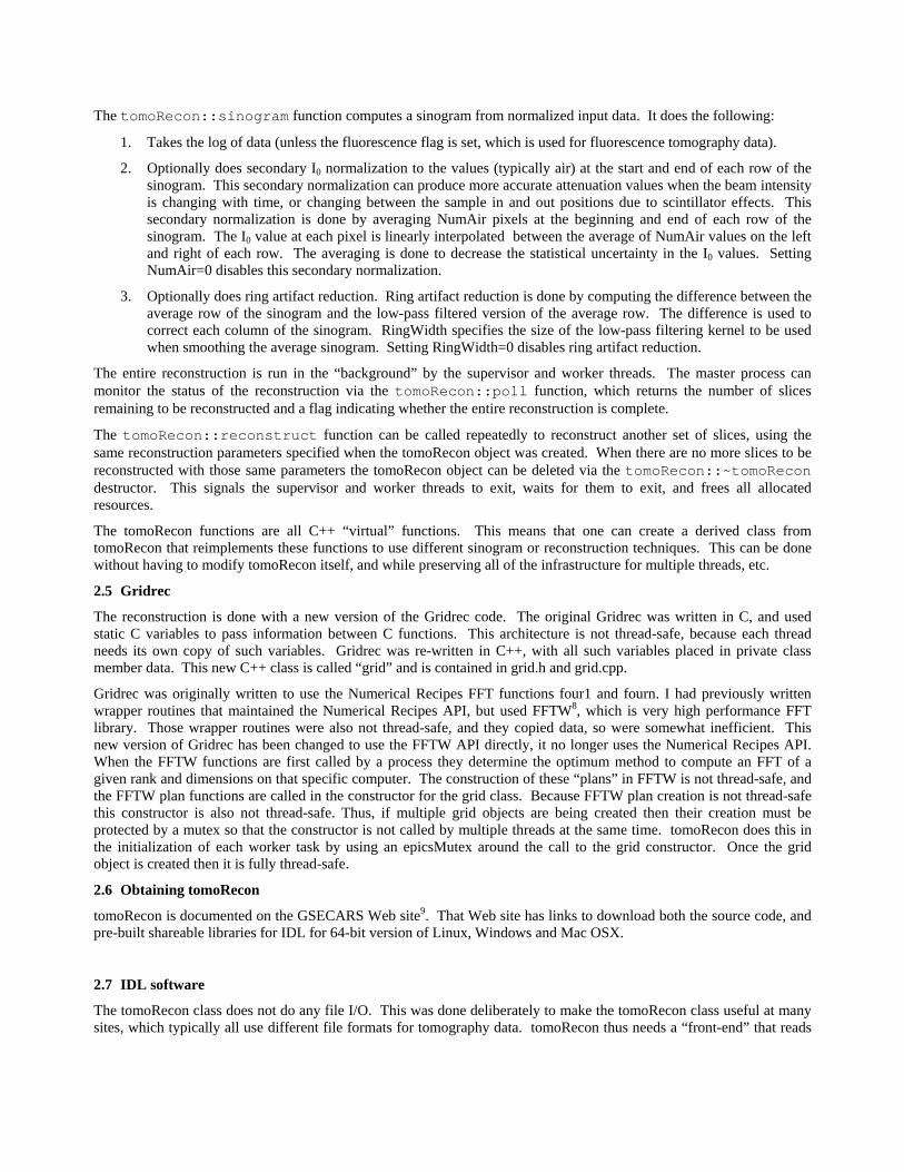
The first performance test was done to measure the time to reconstruct a dataset as a function of the number of threads used in tomoRecon. The input data were all in memory when the tests were run, so the results do not include any file read or write time. These tests were run on both the Windows and Linux computers, though not with the identical datasets because of the relatively small amount of memory (12 GB) on the Linux system. The results are shown in Table 4 and Figure 2.
Table 4. Reconstruction times in seconds for in-memory data as a function of the number of threads used in tomoRecon.
Number of threads
Windows [2048, 256, 1500]
Windows [2048, 2048, 1500]
Linux [1392, 520, 900]
1 69.1 ±0.6 557.9 ±4.5 112.7 ±6.2
2 35.5 ±0.6 282.6 ±1.3 55.4 ±1.5
3 23.7 ±0.1 37.6 ±0.8
4 18.1 ±0.1 144.3 ±0.7 29.6 ±0.6
5 15.0 ±0.1
6 13.4 ±0.8 101.6 ±3.5 20.6 ±0.5
7 12.0 ±0.8 89.9 ±5.2
8 11.8 ±1.4 82.0 ±3.1 17.0 ±1.1
10 11.2 ±0.7 82.2 ±0.4 15.9 ±0.4
12 18.9 ±2.2
16 31.9 ±6.9
Figure 2. Reconstructions times in seconds for in-memory data as a function of the number of threads used in tomoRecon.
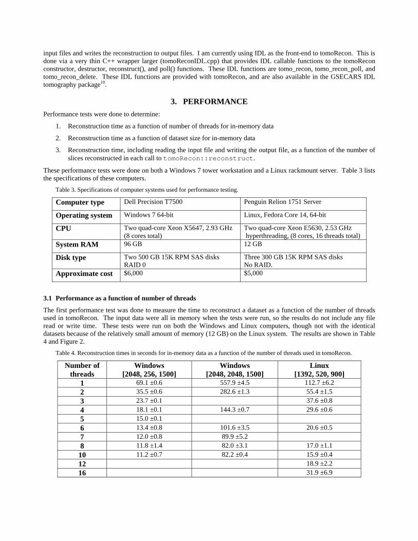
It can be seen in Figure 2 that the initial decrease in execution time with the number of threads is close to the predicted ideal value up to 5 or 6 threads. (The ideal value is the execution time for 1 thread, divided by the number of threads.) For Windows the difference between 7 and 8 threads is small, and there is no improvement between 8 to 10 threads. For Linux there was a minimum execution time with 10 threads, and then a substantial increase as the number of threads was increased to 12 or 16. These results are largely expected, since the number of physical cores is only 8 in each system, and the maximum performance increase that could be hoped for would be the ideal value up to 8 threads. Some fraction of a core is required by the supervisor task and the master IDL task, which are receiving messages and polling for the reconstruction status respectively.
Figure 3 shows the CPU utilization in the Windows Task Manager when running tomoRecon with 1 thread and with 8 threads. With only 1 thread only a single core on the machine is busy, and the overall CPU utilization is only 12%. With 8 threads the system is using all 8 cores, and the CPU utilization is 100%. Under these conditions the Windows computer was still very responsive to operator interaction. This is presumably because the EPICS threads were created with “medium” priority, so that other Windows tasks with higher priority still get a chance to run.
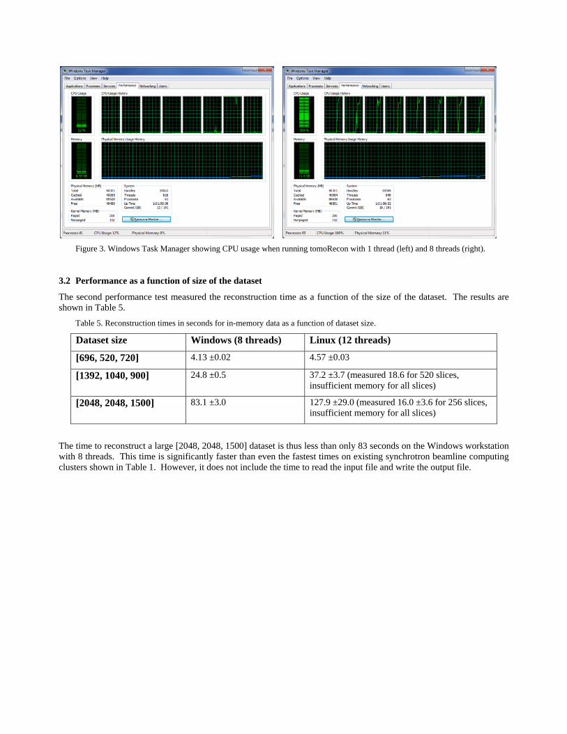
Figure 3. Windows Task Manager showing CPU usage when running tomoRecon with 1 thread (left) and 8 threads (right).
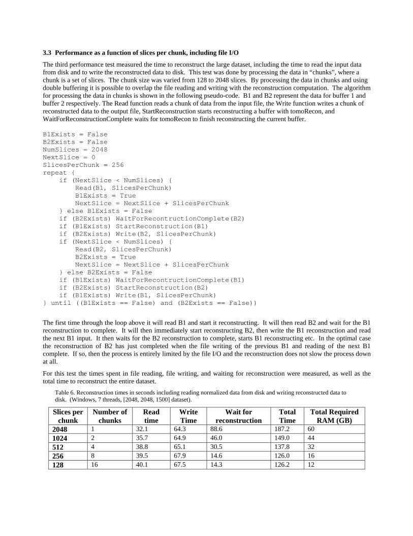
3.2 Performance as a function of size of the dataset
The second performance test measured the reconstruction time as a function of the size of the dataset. The results are shown in Table 5.
Table 5. Reconstruction times in seconds for in-memory data as a function of dataset size.
Dataset size Windows (8 threads) Linux (12 threads)
[696, 520, 720] 4.13 ±0.02 4.57 ±0.03
[1392, 1040, 900] 24.8 ±0.5 37.2 ±3.7 (measured 18.6 for 520 slices, insufficient memory for all slices)
[2048, 2048, 1500] 83.1 ±3.0 127.9 ±29.0 (measured 16.0 ±3.6 for 256 slices, insufficient memory for all slices)
The time to reconstruct a large [2048, 2048, 1500] dataset is thus less than only 83 seconds on the Windows workstation with 8 threads. This time is significantly faster than even the fastest times on existing synchrotron beamline computing clusters shown in Table 1. However, it does not include the time to read the input file and write the output file.
3.3 Performance as a function of slices per chunk, including file I/O
The third performance test measured the time to reconstruct the large dataset, including the time to read the input data from disk and to write the reconstructed data to disk. This test was done by processing the data in “chunks”, where a chunk is a set of slices. The chunk size was varied from 128 to 2048 slices. By processing the data in chunks and using double buffering it is possible to overlap the file reading and writing with the reconstruction computation. The algorithm for processing the data in chunks is shown in the following pseudo-code. B1 and B2 represent the data for buffer 1 and buffer 2 respectively. The Read function reads a chunk of data from the input file, the Write function writes a chunk of reconstructed data to the output file, StartReconstruction starts reconstructing a buffer with tomoRecon, and WaitForReconstructionComplete waits for tomoRecon to finish reconstructing the current buffer. B1Exists = False B2Exists = False NumSlices = 2048 NextSlice = 0 SlicesPerChunk = 256 repeat { if (NextSlice < NumSlices) { Read(B1, SlicesPerChunk) B1Exists = True NextSlice = NextSlice + SlicesPerChunk } else B1Exists = False if (B2Exists) WaitForRecontructionComplete(B2) if (B1Exists) StartReconstruction(B1) if (B2Exists) Write(B2, SlicesPerChunk) if (NextSlice < NumSlices) { Read(B2, SlicesPerChunk) B2Exists = True NextSlice = NextSlice + SlicesPerChunk } else B2Exists = False if (B1Exists) WaitForRecontructionComplete(B1) if (B2Exists) StartReconstruction(B2) if (B1Exists) Write(B1, SlicesPerChunk) } until ((B1Exists == False) and (B2Exists == False))
The first time through the loop above it will read B1 and start it reconstructing. It will then read B2 and wait for the B1 reconstruction to complete. It will then immediately start reconstructing B2, then write the B1 reconstruction and read the next B1 input. It then waits for the B2 reconstruction to complete, starts B1 reconstructing etc. In the optimal case the reconstruction of B2 has just completed when the file writing of the previous B1 and reading of the next B1 complete. If so, then the process is entirely limited by the file I/O and the reconstruction does not slow the process down at all.
For this test the times spent in file reading, file writing, and waiting for reconstruction were measured, as well as the total time to reconstruct the entire dataset.
Table 6. Reconstruction times in seconds including reading normalized data from disk and writing reconstructed data to disk. (Windows, 7 threads, [2048, 2048, 1500] dataset).
Slices per chunk
Number of chunks
Read time
Write Time
Wait for reconstruction
Total Time
Total Required RAM (GB)
2048 1 32.1 64.3 88.6 187.2 60
1024 2 35.7 64.9 46.0 149.0 44
512 4 38.8 65.1 30.5 137.8 32
256 8 39.5 67.9 14.6 126.0 16
128 16 40.1 67.5 14.3 126.2 12
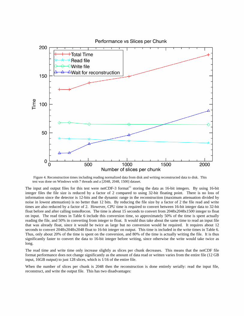
Figure 4. Reconstruction times including reading normalized data from disk and writing reconstructed data to disk. This test was done on Windows with 7 threads and a [2048, 2048, 1500] dataset.
The input and output files for this test were netCDF-3 format11 storing the data as 16-bit integers. By using 16-bit integer files the file size is reduced by a factor of 2 compared to using 32-bit floating point. There is no loss of information since the detector is 12-bits and the dynamic range in the reconstruction (maximum attenuation divided by noise in lowest attenuation) is no better than 12 bits. By reducing the file size by a factor of 2 the file read and write times are also reduced by a factor of 2. However, CPU time is required to convert between 16-bit integer data to 32-bit float before and after calling tomoRecon. The time is about 15 seconds to convert from 2048x2048x1500 integer to float on input. The read times in Table 6 include this conversion time, so approximately 50% of the time is spent actually reading the file, and 50% in converting from integer to float. It would thus take about the same time to read an input file that was already float, since it would be twice as large but no conversion would be required. It requires about 12 seconds to convert 2048x2048x2048 float to 16-bit integer on output. This time is included in the write times in Table 6. Thus, only about 20% of the time is spent on the conversion, and 80% of the time is actually writing the file. It is thus significantly faster to convert the data to 16-bit integer before writing, since otherwise the write would take twice as long.
The read time and write time only increase slightly as slices per chunk decreases. This means that the netCDF file format performance does not change significantly as the amount of data read or written varies from the entire file (12 GB input, 16GB output) to just 128 slices, which is 1/16 of the entire file.
When the number of slices per chunk is 2048 then the reconstruction is done entirely serially: read the input file, reconstruct, and write the output file. This has two disadvantages:
1. The required amount of RAM is large because both the entire input dataset and the entire output dataset must reside in memory simultaneously. In this case 60 GB of memory were required.
2. There is no overlapping of the file I/O with the reconstruction computation. This leads to longer total required time than if the data is reconstructed in smaller chunks where the file I/O and reconstruction can be done simultaneously.
Nearly 90 seconds is spent waiting for reconstruction when the data is processed in a single chunk of 2048 slices. However, when the number of slices per chunk is 256 or 128 the time spent waiting for the reconstruction to complete is less than 15 seconds. This is only about 12% of the total time for the reconstruction, which means that the reconstruction time is largely controlled by the file I/O time, and not by the reconstruction CPU time.
The size of the input file in this example is 2048x2048x1500 pixels stored as 16-bit integers. The file size is thus 11.7 GB, and the data rates reading this file range from to 299 to 374 MB/s. The output file is 2048x2048x2048 pixels, also stored as 16-bit integers. The file size is thus 16.0 GB, and the data rates writing this file range from 241 to 255 MB/s. The total I/O throughput rate during the reconstruction is 27.7 GB / total reconstruction time, and ranges from 151 to 225 MB/s. These data rates are 1.5 to 2.0 times faster than 1 GBit Ethernet speeds. This means that the entire reconstruction can be done more quickly than the input and output files can be copied with GBit Ethernet!
Table 6 shows that a single Windows workstation using tomoRecon can do a complete reconstruction of the [2048, 2048, 1500] dataset, including the time to read the input data, reconstruct and write the output data in just over 2 minutes. This is more than 20 times faster than the equivalent job on the current Linux clusters at 2-BM the APS. (Table 1), and more than 4 times faster than the next fastest system in Table 1.
4. OPTIMIZATION OF ROTATION CENTER
One of the tasks in tomography reconstructions is determination of the pixel containing the rotation center. Ideally this should be determined to sub-pixel accuracy, preferably using an automated technique. It is often necessary to determine the center for each dataset, because of mechanical imperfections in vertical or horizontal translation stages, thermal drifts, etc. If the tomography system is perfectly aligned then the rotation center should be the same for all slices in the sample. However, in reality there may be a slight misalignment of the rotation axis and the columns of the CCD detector, such that there is a systematic change in the optimum rotation axis from the top to bottom of the sample. On our system this misalignment is typically less than 1 pixel, but it is measureable.
The technique that we have found very robust for determining the optimum rotation axis position is based on computing the image entropy12. In this technique the same slice is reconstructed using a range of rotation axis positions. Gridrec can reconstruct with any rotation axis, so it is not necessary to shift the sinogram to vary the rotation axis position. tomoRecon can perform this task very efficiently. One generates a dataset containing the same input slice duplicated N times, and specifies N different rotation axis positions. These reconstructions can then be done in parallel using multiple threads, exactly as is done when reconstructing multiple slices in a dataset. Figure 5 below shows the image entropy for two slices from a 2048 x 2048 x 1500 dataset. A slice 10% down from the top of the sample (slice 205) and a slice 10% up from the bottom of the sample (slice 1843) were reconstructed using 41 different rotation center positions, over a range of ±10 pixels with 0.25 pixel steps. The time to compute all 41 reconstructions was about 4 seconds for each slice on the Windows system. As discussed previously, Gridrec actually reconstructs two slices at the same time, one in the real part of the FFT, and the other in the imaginary part. It uses the rotation center specified for the first slice for the second slice as well. This is the reason that there are always two rotation centers with the same entropy in Figure 5. It can be seen that these two slices have the same rotation center within 0.25 pixel, so the system was well aligned when these data were collected. In the GSECARS reconstruction software the rotation axis positions determined for the slices near the top and bottom of the sample are used to linearly interpolate and extrapolate the rotation axis position used for reconstructing every slice in the dataset.
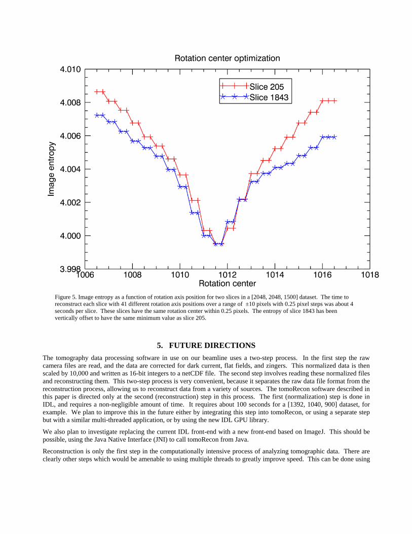
Figure 5. Image entropy as a function of rotation axis position for two slices in a [2048, 2048, 1500] dataset. The time to reconstruct each slice with 41 different rotation axis positions over a range of ±10 pixels with 0.25 pixel steps was about 4 seconds per slice. These slices have the same rotation center within 0.25 pixels. The entropy of slice 1843 has been vertically offset to have the same minimum value as slice 205.
5. FUTURE DIRECTIONS
The tomography data processing software in use on our beamline uses a two-step process. In the first step the raw camera files are read, and the data are corrected for dark current, flat fields, and zingers. This normalized data is then scaled by 10,000 and written as 16-bit integers to a netCDF file. The second step involves reading these normalized files and reconstructing them. This two-step process is very convenient, because it separates the raw data file format from the reconstruction process, allowing us to reconstruct data from a variety of sources. The tomoRecon software described in this paper is directed only at the second (reconstruction) step in this process. The first (normalization) step is done in IDL, and requires a non-negligible amount of time. It requires about 100 seconds for a [1392, 1040, 900] dataset, for example. We plan to improve this in the future either by integrating this step into tomoRecon, or using a separate step but with a similar multi-threaded application, or by using the new IDL GPU library.
We also plan to investigate replacing the current IDL front-end with a new front-end based on ImageJ. This should be possible, using the Java Native Interface (JNI) to call tomoRecon from Java.
Reconstruction is only the first step in the computationally intensive process of analyzing tomographic data. There are clearly other steps which would be amenable to using multiple threads to greatly improve speed. This can be done using
the framework presented here if the analysis code is or can be written in C or C++. A number of higher-level packages, such as IDL, already take advantage of multi-threading and multiple cores for many of their built in calculations.
6. CONCLUSIONS
tomoRecon is a high-performance reconstruction framework that makes use of the multiple cores present on modern CPUs. By running multiple threads simultaneously in a single application process we achieve very high performance on reasonably priced single workstations. tomoRecon out-performs current systems at synchrotron tomography beamlines, including those with large Linux clusters, at about 10% of the cost. It can also be run on the computers available at user’s home institutions, which is very convenient when reprocessing of data is required.
REFERENCES
[1] DeCarlo, F., Advanced Photon Source, Argonne National Laboratory, personal communication [2] Hintermuller, C., Marone, F., Isneffer, A., Stampanoni, M. “Image processing pipeline for synchrotron radiation-
base tomographic microscopy”, J. Synchrotron Radiation 17, 550-559 (2010). [3] Parkinson, D., Advanced Light Source, Lawrence Berkeley National Laboratory, personal communication [4] Dowd, B., Campbell, G. H., Marr, R. B., Nagarkar, V., Tipnis, S., Axe, L., and Siddons, D. P. “Developments in
synchrotron x-ray computed tomography at the National Synchrotron Light Source” Proc. SPIE 3772, 224-236 (1999).
[5] Rivers, M.L., Wang, Y., “Recent developments in microtomography at GeoSoilEnviroCARS”, Proc. SPIE 6318, 63180J (2006).
[6] Marone, F., Munch, B., Stampanoni, M., “Fast reconstruction algorithm dealing with tomography artifacts”, Proc. SPIE 7804, 780410 (2010).
[7] http://www.aps.anl.gov/epics [8] http://www.fftw.org/ [9] http://cars.uchicago.edu/software/epics/tomoRecon.html [10] http://cars.uchicago.edu/software/IDL/tomography.html [11] http://www.unidata.ucar.edu/software/netcdf/ [12] Donath, T., Beckmann, F., Schreyer, A., “Image metrics for the automated alignment of microtomography data”,
Proc. SPIE 6318, 631818 (2006).