Embed Size (px)
Citation preview

Owner's Manual
E 1
Precautions
LocationUsing the unit in the following locations can result in a malfunction.
• In direct sunlight• Locations of extreme temperature or humidity• Excessively dusty or dirty locations• Locations of excessive vibration• Close to magnetic fields
Power supplyPlease connect the designated AC/AC power supply to an AC outlet of the correct voltage. Do not connect it to an AC outlet of voltage other than that for which your unit is intended.
Interference with other electrical devicesRadios and televisions nearby may experience reception interference. Operate this unit at a suitable distance from radios and televisions.
HandlingTo avoid breakage, do not apply excessive force to the switches or controls.
CareIf the exterior becomes dirty, wipe it with a clean, dry cloth. Do not use liquid cleaners such as benzene or thinner, cleaning compounds or flammable polishes.
Keep this manualAfter reading this manual, please keep it for later reference.
Keeping foreign matter out of your equipmentNever set any container with liquid on this equipment. If liquid gets into the equipment, it could cause a breakdown, fire, or electrical shock.Be careful not to let metal objects get into the equipment. If something does slip into the equipment, unplug the AC/AC power supply from the wall outlet. Then contact your nearest Korg dealer or the store where the equipment was purchased.
THE FCC REGULATION WARNING (for U.S.A.)This equipment has been tested and found to comply with the limits for a Class B digital device, pur-suant to Part 15 of the FCC Rules. These limits are designed to provide reasonable protection against harmful interference in a residential installation. This equipment generates, uses, and can radiate radio frequency energy and, if not installed and used in accordance with the instructions, may cause harmful interference to radio communications. However, there is no guarantee that interfer-ence will not occur in a particular installation. If this equipment does cause harmful interference to radio or television reception, which can be determined by turning the equipment off and on, the user is encouraged to try to correct the interference by one or more of the following measures:
• Reorient or relocate the receiving antenna.• Increase the separation between the equipment and receiver.• Connect the equipment into an outlet on a circuit different from that to which the receiver is
connected.• Consult the dealer or an experienced radio/TV technician for help.
Unauthorized changes or modification to this system can void the user’s authority to operate this equipment.
ii
Data HandlingIncorrect operation or malfunction may cause the contents of memory to be lost, so we recom-mend that you save important data on a floppy disk or other media source. Please be aware that Korg will accept no responsibility for any damages which may result from loss of data.
* A United States patent has been obtained for Valve Reactor technology. Patents are pending in other countries. (As of March 2003)
* Company names, product names, and names of formats etc. are the trademarks or registered trademarks of their respective owners.
CE mark for European Harmonized StandardsCE mark which is attached to our company’s products of AC mains operated apparatus until Decem-ber 31, 1996 means it conforms to EMC Directive (89/336/EEC) and CE mark Directive (93/68/EEC). And, CE mark which is attached after January 1, 1997 means it conforms to EMC Directive (89/336/EEC), CE mark Directive (93/68/EEC) and Low Voltage Directive (73/23/EEC).Also, CE mark which is attached to our company’s products of Battery operated apparatus means it conforms to EMC Directive (89/336/EEC) and CE mark Directive (93/68/EEC).
IMPORTANT NOTICE TO CONSUMERS This product has been manufactured according to strict specifications and voltage requirements that are applicable in the country in which it is intended that this product should be used. If you have pur-chased this product via the internet, through mail order, and/or via a telephone sale, you must verify that this product is intended to be used in the country in which you reside.WARNING: Use of this product in any country other than that for which it is intended could be dan-gerous and could invalidate the manufacturer's or distributor's warranty.Please also retain your receipt as proof of purchase otherwise your product may be disqualified from the manufacturer's or distributor's warranty.
iii
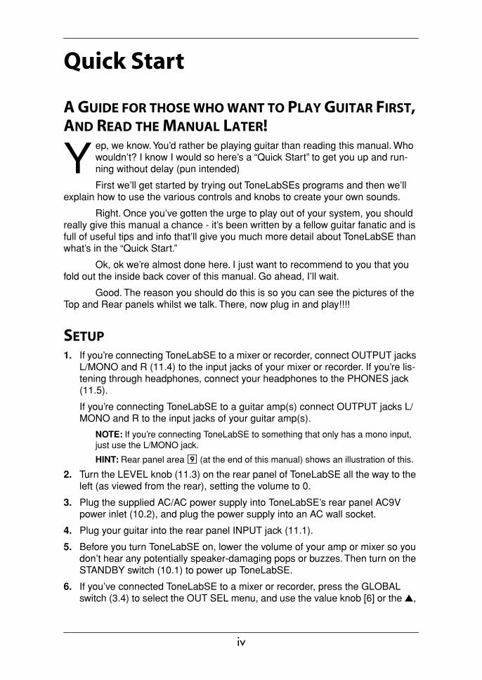
Quick Start
A GUIDE FOR THOSE WHO WANT TO PLAY GUITAR FIRST, AND READ THE MANUAL LATER!
ep, we know. You’d rather be playing guitar than reading this manual. Who wouldn’t? I know I would so here’s a “Quick Start” to get you up and run-ning without delay (pun intended)
First we’ll get started by trying out ToneLabSEs programs and then we’ll explain how to use the various controls and knobs to create your own sounds.
Right. Once you’ve gotten the urge to play out of your system, you should really give this manual a chance - it’s been written by a fellow guitar fanatic and is full of useful tips and info that’ll give you much more detail about ToneLabSE than what’s in the “Quick Start.”
Ok, ok we’re almost done here. I just want to recommend to you that you fold out the inside back cover of this manual. Go ahead, I’ll wait.
Good. The reason you should do this is so you can see the pictures of the Top and Rear panels whilst we talk. There, now plug in and play!!!!
SETUP1. If you’re connecting ToneLabSE to a mixer or recorder, connect OUTPUT jacks
L/MONO and R (11.4) to the input jacks of your mixer or recorder. If you’re lis-tening through headphones, connect your headphones to the PHONES jack (11.5).
If you’re connecting ToneLabSE to a guitar amp(s) connect OUTPUT jacks L/MONO and R to the input jacks of your guitar amp(s).
NOTE: If you’re connecting ToneLabSE to something that only has a mono input, just use the L/MONO jack.
HINT: Rear panel area (at the end of this manual) shows an illustration of this.
2. Turn the LEVEL knob (11.3) on the rear panel of ToneLabSE all the way to the left (as viewed from the rear), setting the volume to 0.
3. Plug the supplied AC/AC power supply into ToneLabSE’s rear panel AC9V power inlet (10.2), and plug the power supply into an AC wall socket.
4. Plug your guitar into the rear panel INPUT jack (11.1).
5. Before you turn ToneLabSE on, lower the volume of your amp or mixer so you don’t hear any potentially speaker-damaging pops or buzzes. Then turn on the STANDBY switch (10.1) to power up ToneLabSE.
6. If you’ve connected ToneLabSE to a mixer or recorder, press the GLOBAL switch (3.4) to select the OUT SEL menu, and use the value knob [6] or the ▲,
Y
9
iv
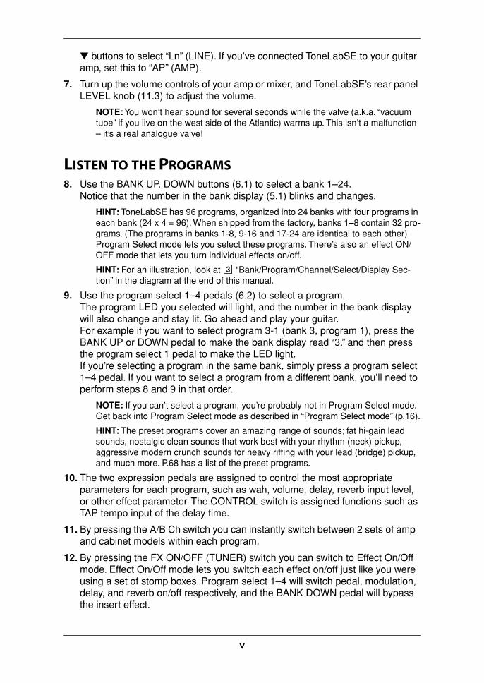
▼ buttons to select “Ln” (LINE). If you’ve connected ToneLabSE to your guitar amp, set this to “AP” (AMP).
7. Turn up the volume controls of your amp or mixer, and ToneLabSE’s rear panel LEVEL knob (11.3) to adjust the volume.
NOTE: You won’t hear sound for several seconds while the valve (a.k.a. “vacuum tube” if you live on the west side of the Atlantic) warms up. This isn’t a malfunction – it’s a real analogue valve!
LISTEN TO THE PROGRAMS8. Use the BANK UP, DOWN buttons (6.1) to select a bank 1–24.
Notice that the number in the bank display (5.1) blinks and changes.
HINT: ToneLabSE has 96 programs, organized into 24 banks with four programs in each bank (24 x 4 = 96). When shipped from the factory, banks 1–8 contain 32 pro-grams. (The programs in banks 1-8, 9-16 and 17-24 are identical to each other) Program Select mode lets you select these programs. There’s also an effect ON/OFF mode that lets you turn individual effects on/off.
HINT: For an illustration, look at “Bank/Program/Channel/Select/Display Sec-tion” in the diagram at the end of this manual.
9. Use the program select 1–4 pedals (6.2) to select a program.The program LED you selected will light, and the number in the bank display will also change and stay lit. Go ahead and play your guitar.For example if you want to select program 3-1 (bank 3, program 1), press the BANK UP or DOWN pedal to make the bank display read “3,” and then press the program select 1 pedal to make the LED light.If you’re selecting a program in the same bank, simply press a program select 1–4 pedal. If you want to select a program from a different bank, you’ll need to perform steps 8 and 9 in that order.
NOTE: If you can’t select a program, you’re probably not in Program Select mode. Get back into Program Select mode as described in “Program Select mode” (p.16).
HINT: The preset programs cover an amazing range of sounds; fat hi-gain lead sounds, nostalgic clean sounds that work best with your rhythm (neck) pickup, aggressive modern crunch sounds for heavy riffing with your lead (bridge) pickup, and much more. P.68 has a list of the preset programs.
10. The two expression pedals are assigned to control the most appropriate parameters for each program, such as wah, volume, delay, reverb input level, or other effect parameter. The CONTROL switch is assigned functions such as TAP tempo input of the delay time.
11. By pressing the A/B Ch switch you can instantly switch between 2 sets of amp and cabinet models within each program.
12. By pressing the FX ON/OFF (TUNER) switch you can switch to Effect On/Off mode. Effect On/Off mode lets you switch each effect on/off just like you were using a set of stomp boxes. Program select 1–4 will switch pedal, modulation, delay, and reverb on/off respectively, and the BANK DOWN pedal will bypass the insert effect.
3
v
SWITCHING EFFECTS ON/OFF13. The model select buttons will be lit (ON) or dark (OFF) to indicate the on/off
state of each effect. If you press a button that is dark or turn the model selec-tor, the effect will turn on and the model select button will blink. If you press a button that is blinking, the effect will turn off and the button will go dark.
CREATE YOUR OWN SOUNDS14. To adjust the sound of the AMP model, use the AMP selector to select one of
the sixteen amp models. Then you can simply adjust the sound pretty much in the same way as if you were really using the actual model of guitar amp you selected.Adjust the GAIN value knob 1, TREBLE value knob 3, MIDDLE value knob 4, BASS value knob 5, and the VR GAIN value knob 2 (which corresponds to the MASTER) as you like. To get the most accurate vintage tube amp distortion, raise the VR GAIN as high as possible. The CH VOLUME value knob 6 lets you adjust the volume while retaining the overall sound including the distortion pro-duced by the Valve Reactor.If you press the PRES-NR button, you can then use value knob 3 to adjust PRESENCE and value knob 4 to adjust the NR (Noise Reduction) effect.When you use the AMP MODEL and CABINET MODEL selectors, a different type of guitar amp will appear before your very eyes – or, should we say, ears! ToneLabSE holds in its memory two combinations of amp and cabinet models for each program, and you can use the A/B ch pedal to switch instantly between these.
HINT: P.34 lists recommended combinations of amp and cabinet models but others are fine too.
HINT: If you want to replicate the sound of the original amp, set [VR GAIN] to the maximum setting on vintage-type models that do not have a master volume control (i.e., AC15, AC15TB, AC30, AC30TB, UK BLUES, UK 68P, BLACK 2x12, TWEED 1x12, and TWEED 4x10). For modern-type amps that have a master volume con-trol, adjust [VR GAIN] in the same way that you would on the original amp. When the [VR GAIN] setting is low, preamp-type distortion will occur. As you raise the [VR GAIN] setting, the pre-amp will begin loading the Valve Reactor to cause clipping, and the warmth and distortion of the Valve Reactor will be added.
HINT: For an illustration, look at area in the top panel diagram at the end of this manual.
1
vi

15. ToneLabSE provides a PEDAL effect that is placed before the amp, and MOD-ULATION, DELAY, and REVERB effects that are placed after the cabinet.For example if you want use the PEDAL effect TREBLE BOOST, turn the PEDAL selector to select TREBLE BOOST. The PEDAL parameter LED of the edit section will blink, indicating the parameter line (the region listing the parameter names). Also, the LEDs below the value knobs will light, indicating the location of the knobs that you can use to control TREBLE BOOST. Now turn value knobs 1, 2, and 3 to adjust DRIVE, LEVEL, and TONE respectively. You can edit other effects using the same procedure.
HINT: Some effect settings may cause unwanted distortion (if there is such a thing!!). If this happens, lower the CH VOLUME.
HINT: For an illustration, look at area in the top panel diagram at the end of this manual.
2
vii
Table of Contents
Quick Start................................................................................................... ivSetup....................................................................................................................... iv
Listen to the Programs.............................................................................................v
Switching effects on/off ........................................................................................... vi
Create your own Sounds ........................................................................................ vi
Introduction ................................................................................................. 1Main Features..........................................................................................................1
Valve Reactor Technology.......................................................................................2
An overview of ToneLabSE .....................................................................................4Signal Route .....................................................................................................4Modes ...............................................................................................................4Amp and effect settings (Edit)...........................................................................4Realtime expression and control pedals..........................................................4Saving a program .............................................................................................4MIDI and output destination settings ................................................................4
A Guitarist’s Guided Panel Tour ................................................................. 5The Top Panel .........................................................................................................5
Model select section ........................................................................................5 Edit section ......................................................................................................7 Chain/Global/Rename/Write/Exit/Display section............................................8 Control Setup section ......................................................................................9 Bank display/Tuner display..............................................................................9 Bank/Program/Channel/Select section ............................................................9 FX ON/OFF Switch ........................................................................................10 Effect control section .....................................................................................10 Valve..............................................................................................................10
Rear panel .............................................................................................................11 Power supply .................................................................................................11 Inputs and Outputs ........................................................................................11 MIDI ...............................................................................................................11
Setup........................................................................................................... 13Output settings.......................................................................................................13
Basic connections..................................................................................................13
Using ToneLabSE with a mixer or recorder ...........................................................14Example of connections to a mixer or recorder ..............................................14
Using ToneLabSE with a guitar amp(s) .................................................................15Example of connection to a guitar amp (or amps) ..........................................15
Using ToneLabSE with a MIDI device or computer ...............................................15
Playing ToneLabSE .................................................................................... 16
viii
Program Select mode ............................................................................................16Selecting a program........................................................................................16
Effect On/Off mode ................................................................................................16Switching effects on/off...................................................................................17A/B Channel Hold ...........................................................................................17
Activating or deactivating the Key Lock function....................................................18Activating the Key Lock function.....................................................................18Deactivating the Key Lock function.................................................................18
Creating and Storing your own Programs............................................... 19Creating your own Program...................................................................................19
Changing the connection order of the effects (CHAIN)..........................................21
Naming a program .................................................................................................21
Storing a program ..................................................................................................22
Restoring a setting to its original value (Original Value) ........................................22
Explanations of the Amp, Cabinet and Effect Types............................... 23A. AMP Models ......................................................................................................23
B. CABINET Models ..............................................................................................32WHAT GOES WITH WHAT? ..........................................................................34
C. PEDAL Effects...................................................................................................35
D. MOD (Modulation) effects .................................................................................39
E. DELAY effects ...................................................................................................45
F. REVERB effects ................................................................................................48
Tuner (Bypass, Mute)................................................................................. 51Tuning procedure...................................................................................................51
Calibrating the tuner...............................................................................................52
Using the expression pedals..................................................................... 53Expression pedal settings......................................................................................53
Expression Target Quick Assign.....................................................................53Setting the Expression Target ........................................................................54Expression pedal control initialization settings ...............................................55
Control switch settings ...........................................................................................56Switching each effect on/off............................................................................56Using TAP TEMPO to set a parameter...........................................................56FACTOR value knob 2 setting ........................................................................56Effect control...................................................................................................57
Adjusting the sensitivity of the pedals ....................................................................57Expression pedal 1 .........................................................................................57Expression pedal 2 .........................................................................................58
Control via MIDI ......................................................................................... 59Connecting a MIDI Device or Computer ................................................................59
Setting the MIDI Channel (GLOBAL “MIDI CH”)....................................................60
ix

Program Change (GLOBAL “PCHG OUT”) ...........................................................60
Control Change (GLOBAL “CCHG I/O”) ................................................................60
Parameter Change (GLOBAL “SYEX OUT”) .........................................................61
Backing up and Restoring Program Data (GLOBAL “DUMP CUR,” DUMP ALL”).62Backing Up .....................................................................................................62Restoring ........................................................................................................63
Restoring the Factory Preset Programs................................................... 64
Troubleshooting ........................................................................................ 65
Specifications............................................................................................. 67
Program list................................................................................................ 68
Index ........................................................................................................... 69
x

Intro
ducti
onPa
nel T
our
Setu
pPl
ayin
gCr
eatin
gan
d St
orin
g
Introduction
WELCOME ABOARD!any thanks for adding the VOX Valvetronix ToneLabSE to your sonic arsenal. We’re sure it’ll give you countless hours of great guitar tones that will feel as good as they sound!
To maximize your chances of enjoying a long and happy relationship with your ToneLabSE, please read this manual at least once, and (as they say), “use the product as directed.” Keep the manual for future reference after you’ve read it; you’ll want to re-read it later at some point to pick up cool tips you may have missed the first time around.
MAIN FEATURES• ToneLabSE features Valve Reactor technology that switches between Class A
and Class AB power amp circuits with an actual 12AX7 (ECC 83) miniature tri-ode valve (vacuum tube) to create the sound of an actual tube power amp, delivering the response and tone of classic amps.
• ToneLabSE uses sophisticated modeling technology to create classic amp, cab-inet, and effect sounds. You can choose from sixteen amp types that include classic vintage amps and expensive high-end valve amps, and eleven different cabinet types. By combining amp types and cabinet types you can create an amazing range of sounds, many of which have never been heard before.
• Since high-quality effects are built in, ToneLabSE is all you need to create a completely finished sound. Sixteen types of pedal effects are placed before the amp, and after the cabinet are eleven types of modulation, eleven types of delay, and eleven types of reverb. You can choose one type for each effect, and use these four effects simultaneously plus Noise Reduction.
• You can store all of your own amp settings and effect model settings as a “pro-gram” in one of 96 program memories. ToneLabSE comes with 32 preset pro-grams for instant gratification.
• Manual Mode lets you use ToneLabSE just like conventional amps and effects. The sound will be exactly as specified by the physical positions of the amp sec-tion knobs. In other words...what you see is what you get!
• For convenient tuning, an Auto Chromatic Tuner is built-in.• There are two expression pedals that you can use as a wah pedal, volume
pedal, or to control a variety of effect parameters – a great feature for live perfor-mance.
• There’s a Quick Assign function that makes it easy to assign parameters to the expression pedal.
• ToneLabSE provides control switches that let you do things like set the delay time via TAP TEMPO, switch insert effects on/off, or switch the speed of a rotary speaker ... again, must-have features for live performance.
M
1
• You can use the effect insert jacks to connect an external effect processor or stompbox.
• With MIDI IN and OUT connectors, ToneLabSE gives you plenty of potential for expanding your system.
• ToneLabSE Sound Editor is an editor/librarian software that lets you visually edit ToneLabSE’s numerous parameters, and save and manage programs.To obtain the “ToneLabSE Sound Editor,” please contact the VOX distributor in your country or download the latest version from: “http://www.voxamps.co.uk” or “http://www.valvetronix.com/”To find your local Distributor go to: “http://www.voxamps.co.uk/dealers/worldwid.htm”
VALVE REACTOR TECHNOLOGY
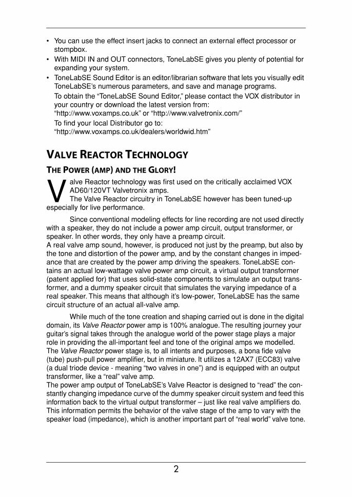
THE POWER (AMP) AND THE GLORY!alve Reactor technology was first used on the critically acclaimed VOX AD60/120VT Valvetronix amps. The Valve Reactor circuitry in ToneLabSE however has been tuned-up
especially for live performance.
Since conventional modeling effects for line recording are not used directly with a speaker, they do not include a power amp circuit, output transformer, or speaker. In other words, they only have a preamp circuit.A real valve amp sound, however, is produced not just by the preamp, but also by the tone and distortion of the power amp, and by the constant changes in imped-ance that are created by the power amp driving the speakers. ToneLabSE con-tains an actual low-wattage valve power amp circuit, a virtual output transformer (patent applied for) that uses solid-state components to simulate an output trans-former, and a dummy speaker circuit that simulates the varying impedance of a real speaker. This means that although it’s low-power, ToneLabSE has the same circuit structure of an actual all-valve amp.
While much of the tone creation and shaping carried out is done in the digital domain, its Valve Reactor power amp is 100% analogue. The resulting journey your guitar’s signal takes through the analogue world of the power stage plays a major role in providing the all-important feel and tone of the original amps we modelled.The Valve Reactor power stage is, to all intents and purposes, a bona fide valve (tube) push-pull power amplifier, but in miniature. It utilizes a 12AX7 (ECC83) valve (a dual triode device - meaning “two valves in one”) and is equipped with an output transformer, like a “real” valve amp.The power amp output of ToneLabSE’s Valve Reactor is designed to “read” the con-stantly changing impedance curve of the dummy speaker circuit system and feed this information back to the virtual output transformer – just like real valve amplifiers do. This information permits the behavior of the valve stage of the amp to vary with the speaker load (impedance), which is another important part of “real world” valve tone.
V
2
Intro
ducti
onPa
nel T
our
Setu
pPl
ayin
gCr
eatin
gan
d St
orin
g
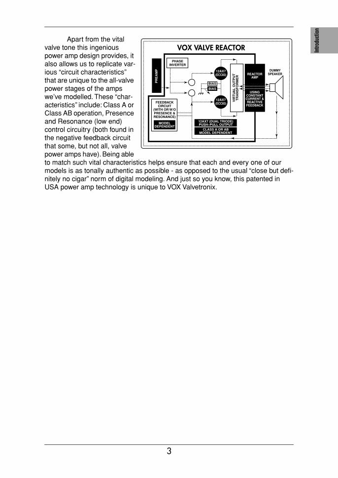
Apart from the vital valve tone this ingenious power amp design provides, it also allows us to replicate var-ious “circuit characteristics” that are unique to the all-valve power stages of the amps we’ve modelled. These “char-acteristics” include: Class A or Class AB operation, Presence and Resonance (low end) control circuitry (both found in the negative feedback circuit that some, but not all, valve power amps have). Being able to match such vital characteristics helps ensure that each and every one of our models is as tonally authentic as possible - as opposed to the usual “close but defi-nitely no cigar” norm of digital modeling. And just so you know, this patented in USA power amp technology is unique to VOX Valvetronix.
VOX VALVE REACTOR
FEEDBACKCIRCUIT
(WITH OR W/O PRESENCE & RESONANCE)
REACTORAMP
USING CONSTANTCURRENT &REACTIVEFEEDBACK
MODELDEPENDENT
12AX7 (DUAL TRIODE)PUSH–PULL OUTPUT
PR
EA
MP
VIR
TU
AL
OU
TP
UT
T
RA
NS
FO
RM
ER
CLASS A OR ABMODEL DEPENDENT
PHASEINVERTER
DUMMYSPEAKER
12AX7(ECC83)
12AX7(ECC83)
BIAS
BIAS
3
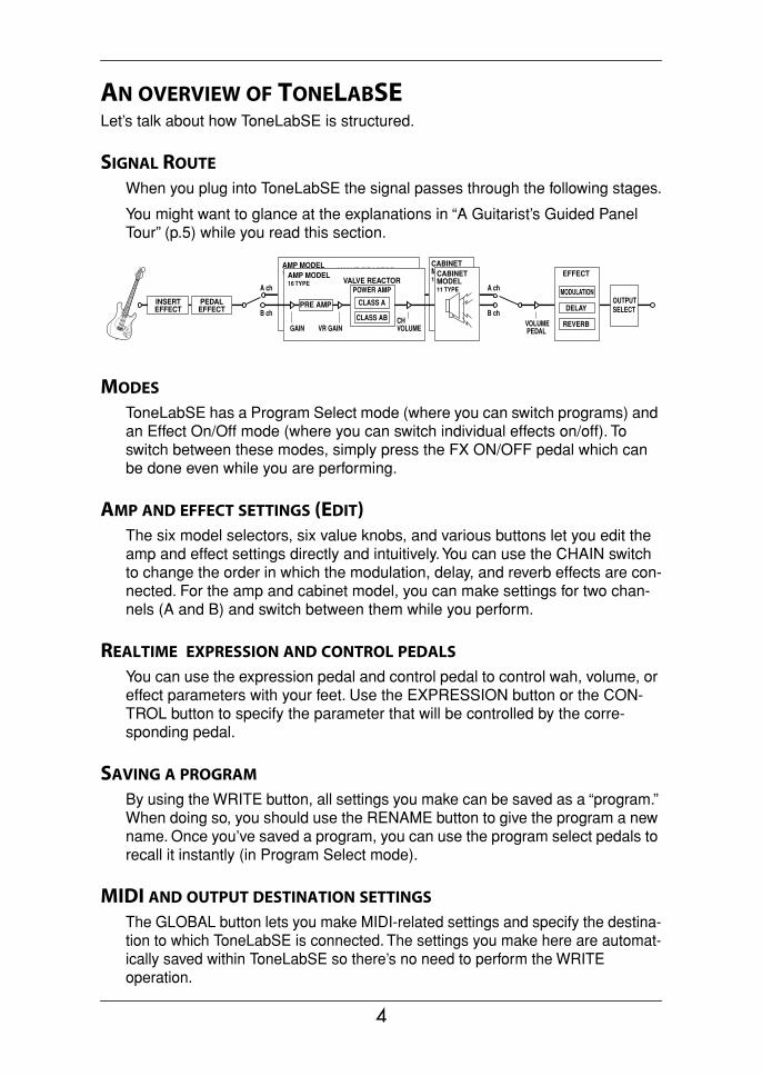
AN OVERVIEW OF TONELABSELet’s talk about how ToneLabSE is structured.
SIGNAL ROUTE
When you plug into ToneLabSE the signal passes through the following stages.
You might want to glance at the explanations in “A Guitarist’s Guided Panel Tour” (p.5) while you read this section.
MODES
ToneLabSE has a Program Select mode (where you can switch programs) and an Effect On/Off mode (where you can switch individual effects on/off). To switch between these modes, simply press the FX ON/OFF pedal which can be done even while you are performing.
AMP AND EFFECT SETTINGS (EDIT)The six model selectors, six value knobs, and various buttons let you edit the amp and effect settings directly and intuitively. You can use the CHAIN switch to change the order in which the modulation, delay, and reverb effects are con-nected. For the amp and cabinet model, you can make settings for two chan-nels (A and B) and switch between them while you perform.
REALTIME EXPRESSION AND CONTROL PEDALS
You can use the expression pedal and control pedal to control wah, volume, or effect parameters with your feet. Use the EXPRESSION button or the CON-TROL button to specify the parameter that will be controlled by the corre-sponding pedal.
SAVING A PROGRAM
By using the WRITE button, all settings you make can be saved as a “program.” When doing so, you should use the RENAME button to give the program a new name. Once you’ve saved a program, you can use the program select pedals to recall it instantly (in Program Select mode).
MIDI AND OUTPUT DESTINATION SETTINGS
The GLOBAL button lets you make MIDI-related settings and specify the destina-tion to which ToneLabSE is connected. The settings you make here are automat-ically saved within ToneLabSE so there’s no need to perform the WRITE operation.
AMP MODEL16 TYPE
GAIN
VALVE REACTOR
CLASS A
CLASS AB
POWER AMP
CABINET MODEL10 TYPE
VR GAIN
PRE AMP
CH VOLUME
PEDALEFFECT
INSERTEFFECT
AMP MODEL16 TYPE
GAIN
VALVE REACTOR
CLASS A
CLASS AB
POWER AMPOUTPUTSELECT
CABINET MODEL11 TYPE
VR GAIN
PRE AMP
CH VOLUME
VOLUME PEDAL
MODULATION
DELAY
REVERB
EFFECT
A ch
B ch
A ch
B ch
4

Intro
ducti
onPa
nel T
our
Setu
pPl
ayin
gCr
eatin
gan
d St
orin
g
A Guitarist’s Guided Panel TourHere we’re going to learn about the buttons and other controls on ToneLabSE’s top and rear panel.
HINT: The inside back cover of this manual folds out to reveal a big picture of ToneLabSE’s top panel, rear panel, and display. Leave this folded out as you con-tinue reading so you’ll be able to see the panel diagram while you read about each section.
THE TOP PANEL
MODEL SELECT SECTION
Here you can select the model of amp, cabinet and effect models.
1.1 MODEL select buttonsUse these when selecting the effect category you want to edit with value knobs 1–6, and when switching effects on/off. If an effect you’re using is ON it will be lit (or blinking during editing), and if OFF it will be dark.
Press a button once and its LED will blink; now you can use value knobs 1–6 to edit the parameters of that effect.
If you want turn off an effect that is currently on, press the model select button for the appropriate effect once (it blinks), and then press that model switch but-ton once again to turn it off (dark); the name display will indicate [--OFF--].
The pedal effect is placed in front of the amp model and the modulation, delay, and reverb are placed after the cabinet model.
NOTE: While the cabinet model select button is blinking, you can use the value knobs to adjust the parameters of the amp model.
NOTE: The amp and cabinet model select buttons will change color depending on the channel you select; they will be lit (or blinking) green when channel A is selected, and red when channel B is selected.
NOTE: The reason that modulation, delay, and reverb effects are placed after the amp — rather than before it as a “stompbox” would be — is that they sound better and more realistic. For example, REVERB emulates the sound created by a room or hall. So, logic dictates that if we’re going to add it to our sound, the closer to the end of the signal chain we put it, the more “real” and natural it’s going to sound. The same is true for DELAY and MODULATION effects — they’re going to sound more natural if added near the end of your signal path, not at its beginning. Also, if you’re using a crunch or high gain lead sound then it makes much more sense to add effects like ROTARY, ROOM (reverb), or DELAY after it’s been distorted, rather than before.
1.2 INSERT buttonUse this to switch the insert effect on/off. This will be lit if the signal input/output to the external effect is ON, or dark if it is OFF. The external effect is placed before the pedal effect.
1
5
1.3 PRES-NR (Presence/Noise Reduction) buttonUse this to change the presence and noise reduction settings of the amp. While this button is blinking, you can use value knob [3] to adjust the presence, and value knob [4] to adjust the noise reduction. This will light (blink) green when channel A is selected, or red when channel B is selected.
1.4 PEDAL selectorThis lets you select one of the sixteen pedal effect models ToneLabSE offers. When you turn the PEDAL selector, the PEDAL select button will blink, and you can use value knobs 1–6 to adjust the pedal effect parameters. (For an expla-nation of each effect, refer to p.35–.) As stated before, pedal effects are con-nected before the amp.
NOTE: The parameters will be initialized when you switch effect types.
1.5 AMP MODEL selectorThis lets you select from sixteen types of classic amp models, including the legendary VOX AC30TBX. (For details, see p.23.) When you turn the AMP MODEL selector, the AMP MODEL select button will blink, and you can use value knobs 1–6 to adjust its parameters.
The operating mode of the preamp and power amp, the response of the tone controls, and their placement within the circuit will change depending on the type of amp you select here, precisely replicating the exact gain and tonal character of the original amp. The all-important power amp stage (class A or AB) and negative-feedback circuit (or lack thereof) are also carefully simulated.
1.6 CABINET MODEL selectorThis selects one of eleven cabinet models that replicate the shape and size of the cabinet and the type and number of its speakers. (For details, refer to p.32.) When you turn the CABINET MODEL selector, the CABINET MODEL select button will blink.
NOTE: While the CABINET MODEL select button is blinking, you can use the value knobs to adjust its parameters.
1.7 MODULATION selectorThis selects one of eleven modulation effect models. When you turn the MOD-ULATION selector, the MODULATION select button will blink, and you can use value knobs 1–6 to adjust the parameters of the modulation effect. (For details on each effect, refer to p.39–.)
NOTE: The parameters will be initialized when you switch effect types.
1.8 DELAY selectorThis selects one of eleven delay effect models. When you turn the DELAY selector, the DELAY select button will blink, and you can use value knobs 1–6 to adjust the parameters of the delay effect. (For details on each effect, refer to p.45–.)
NOTE: The parameters will be initialized when you switch effect types.
6
Intro
ducti
onPa
nel T
our
Setu
pPl
ayin
gCr
eatin
gan
d St
orin
g
1.9 REVERB selectorThis selects one of eleven reverb effect models. When you turn the REVERB selector, the REVERB select button will blink, and you can use value knobs 1–6 to adjust the parameters of the reverb effect. (For details on each effect, refer to p.48–.)
NOTE: The parameters will be initialized when you switch effect types.
EDIT SECTION
2.1 Edit category LEDsOne of the LEDs will blink to indicate the category of effect you are currently editing.When adjusting the parameters, an LED will blink to indicate the line of param-eter names that you are adjusting.
2.2 Value knobs 1–6Use these to adjust the parameters of the effects or amp model. Your adjust-ments will modify the effect whose MODEL select button you pressed (i.e., the button that is blinking). The LEDs below the knobs will light to indicate the knobs that are available.
For details on the parameter controlled by each knob, refer to p.35–. (From the left, we refer to these as value knobs 1–6.)
When the EXPRESSION button or CONTROL button is blinking, these knobs adjust the corresponding functions.
When you are making RENAME or GLOBAL settings, or when executing the WRITE operation, you can use value knob 6 to change values.
2
7

CHAIN/GLOBAL/RENAME/WRITE/EXIT/DISPLAY SECTION
This area displays the name of the program, and the name and value of the parameter you are editing in the amp or effect section. Use RENAME to edit the name of the program, and WRITE to save the program.
CHAIN lets you change the connection order of the modulation, delay, and reverb effects. GLOBAL lets you make MIDI and output settings.
3.1 ▲, ▼ buttonsUse these to edit the value of parameters.
3.2 √√√√, ®®®® buttonsUse these to select the parameter you want to edit, or to edit the program name.
3.3 CHAIN buttonUse this to change the connection order of the modulation, delay, and reverb effects. Use value knob 6 or the ▲, ▼ buttons to edit the value.
3.4 GLOBAL buttonUse this to make settings related to MIDI or to ToneLabSE’s audio output.
Press the GLOBAL button and use the √√√√, ®®®® buttons to move through the menu items in the order shown below. After you have selected a menu item, use value knob 6 or the ▲, ▼ buttons to adjust the value.
3.5 RENAME buttonUse this to change the program name (p.21).
Use the √√√√, ®®®® buttons to move between spaces (characters) in the display, and use value knob 6 or the ▲, ▼ buttons to change the character at that space.
3.6 WRITE buttonUse this when you want to save the settings you’ve created (p.22).
3.7 EXIT buttonUse this to abort a program-write operation or to cancel a GLOBAL setting.
By pressing and holding this button for a longer time, you can activate/cancel the Key Lock function, which disables operation of the buttons, selectors, and knobs (p.18).
OUT SEL: Specifies the output destination (p.13)CH HOLD: Specifies whether the channel (A/B) selection will be
maintained when you switch programs(p.17)
MIDI CH: Specifies the MIDI channel (p.59)PCHG OUT: Specifies the program change message output setting (p.60)CCHG I/O: Specifies the control change message input/output setting(p.60)SYEX OUT: Specifies the system exclusive message output setting (p.61)DUMP CUR: Dumps the current program data from the MIDI OUT con-
nector(p.62)
DUMP ALL: Dumps all of ToneLabSE’s data from the MIDI OUT con-nector
(p.62)
3
8
Intro
ducti
onPa
nel T
our
Setu
pPl
ayin
gCr
eatin
gan
d St
orin
g
3.8 Name displayDisplays program names, effect names, or parameter names.
3.9 Valve iconIndicates the number and type of power valve – a.k.a. “vacuum tube” – used in the original amp that is being modeled.
3.10 Value displayIndicates the value of the parameter you are editing.
If the displayed parameter value matches the original value (i.e., the value saved in the program), the ORIG (original value) icon will appear.
If you have edited any parameter of the program, the EDIT icon will appear.
CONTROL SETUP SECTION
4.1 CONTROL pedal setting buttonUse this to make control pedal settings. While this button is blinking, you can use value knobs 1–2 to edit the control pedal settings.
4.2 EXPRESSION pedal setting buttonUse this to make expression pedal settings. While this button is blinking, you can use value knobs 1–6 to edit the expression pedal settings.
If this is lit while you’re editing, the expression pedal Quick Assign function is available.
HINT(Quick Assign): If the expression pedal setting button is lit while you are edit-ing an effect, you can use the expression pedal Quick Assign function. To assign the parameter shown in the name display to expression pedal 1, simply press and hold the expression pedal setting button for one second. If you want to assign the parameter to expression pedal 2, press and hold the control pedal setting button for one second. When the assignment is completed, the name display will indicate COMPLETE.
BANK DISPLAY/TUNER DISPLAY
5.1 Bank displayIndicates the bank number. If the tuner is operating, this indicates the note name. (p.51)
5.2 Tuner displayIf the tuner is on, this displays the pitch you are playing. (p.51)
BANK/PROGRAM/CHANNEL/SELECT SECTION
6.1 BANK UP/DOWN pedalsIn Program Select mode, press BANK UP to increment the bank by one, or BANK DOWN to decrement it by one. In Effect On/Off mode, you can use the BANK DOWN pedal to switch INSERT (the external effect) on/off.
6.2 Program select pedals, Program LEDsUse these to select programs. The program LED at the upper left of each pedal will light accordingly.
4
5
6
9

In Effect On/Off mode, these switches individually switch the Pedal, Modula-tion, Delay, and Reverb effects on/off.
6.3 A/B ch channel select pedal, Channel LEDsUse this to change channels within the currently selected program. The chan-nel LEDs located above the pedal will light accordingly (green when channel A is selected, red when channel B is selected).
FX ON/OFF SWITCH
Press this switch when you want to switch to Effect On/Off mode and the LED at the upper left of the pedal will light.
In Effect On/Off mode you can use the program select pedals to individually switch the Pedal, Modulation, Delay, and Reverb effects on/off.
If you press and hold this switch for 0.5 seconds or longer, the output will be bypassed. If you press and hold this pedal for one second or longer, the output will be muted. The tuner will operate when ToneLabSE is bypassed or muted.
To cancel bypass or mute (Tuner), press this switch once again.
EFFECT CONTROL SECTION
8.1 CONTROL (Control switch)This pedal controls the effect function specified by the Control switch setting.
8.2 EXP1, EXP2 (Expression pedal 1, Expression pedal 2)These pedals control the effect parameter you assigned as the expression pedal setting; e.g., volume, wah, or other effect parameter. Pressing down firmly on an expression pedal will activate a switch underneath the pedal, let-ting you turn the assigned effect on/off (except when you’ve assigned volume or an amp parameter).
VALVE
9.1 Valve windowToneLabSE contains a 12AX7 (ECC83) valve (“vacuum tube”).
NOTE: The valve cover and or valve may break if it’s subjected to impact. If the valve cover breaks, please have it replaced; leaving a damaged cover may lead to the valve itself to become damaged.
7
8
9
10
Intro
ducti
onPa
nel T
our
Setu
pPl
ayin
gCr
eatin
gan
d St
orin
g
REAR PANEL
POWER SUPPLY
10.1 ~AC9VConnect the included AC/AC power supply here.
10.2 STANDBY buttonTurns the power on/off.
INPUTS AND OUTPUTS
11.1 INPUT jackConnect your guitar to this jack.
11.2 INSERT jacks (SEND, RETURN)You can connect an external effect processor or stompbox to these jacks.
Connect SEND to the input of your external effect device.
Connect RETURN to the output of your external effect device.
11.3 LEVEL knobAdjusts the output level from the OUTPUT jacks and the PHONE jack.
11.4 OUTPUT jacks (L/MONO, R)These are analog output jacks (balanced/unbalanced TRS). If you’re using a mono output, connect the L/MONO jack.
11.5 PHONE jack (stereo)Connect your headphones to this jack.
MIDI12.1 MIDI OUT connectorThis connector transmits MIDI data. Use it when you want to control a con-nected external MIDI device.
12.2 MIDI IN connectorThis connector receives MIDI data. Use it when you want to control ToneLabSE from a connected external MIDI device.
10
11
12
11

12

Intro
ducti
onPa
nel T
our
Setu
pPl
ayin
gCr
eatin
gan
d St
orin
g
SetupNOTE: You must turn off the power of all your equipment before you make connec-tions. If you ignore this warning, you may damage your speaker system or experi-ence malfunctions!
OUTPUT SETTINGSHere’s how to specify whether you’re connecting ToneLabSE to a guitar amp or to a mixer/recorder.
1. Press the GLOBAL button, and use the √√√√, ®®®® buttons to make the display read “OUT SEL.”
2. Use value knob 6 or the ▲, ▼ buttons to set the value.
NOTE: With the factory settings, “AP” is selected.
BASIC CONNECTIONS1. Use audio cables to connect ToneLabSE’s OUTPUT L/MONO and R jacks
(11.4) to a mixer/recorder or guitar amp (p.13, 14). If desired, you can also connect an external effect processor. To do this simply connect SEND to the input of your external processor, and RETURN to the output of your external processor.
NOTE: If you’re making connections in mono, use the OUTPUT L/MONO jack. However to take the fullest advantage of ToneLabSE’s sound, we strongly recom-mend that you use stereo connections.
If you are using headphones, plug them into the PHONES jack (11.5).
NOTE: Signal from the OUTPUT jack(s) will still be heard even if headphones are plugged in. If you only want to hear signal from headphones you must disconnect any cables from the Output jacks or turn off or lower any equipment ToneLabSE is connected to.
2. Turn the LEVEL knob (11.3) located on the rear panel of ToneLabSE all the way toward the left (as seen from the rear), setting the volume to 0.
3. Connect the included AC/AC power supply to the rear panel AC9V power sup-ply jack (10.2), and then connect the plug to an AC outlet.
4. Plug your guitar into the rear panel INPUT jack (11.1).
5. Turn down the volume of your amp or mixer so you don’t hear crackles or pops when the power is turned on. Then turn on the STANDBY switch (10.1) to turn on the power.
When connecting to a guitar amp When connecting to a mixer/recorder
13

6. If you’ve connected ToneLabSE to a mixer/recorder, press the GLOBAL switch to access the OUT SEL menu, and use value knob 6 or the ▲, ▼ buttons to select “Ln” (LINE). If you’ve connected ToneLabSE to a guitar amp, select “AP” (AMP).
7. To adjust the volume, turn up your amp or mixer and ToneLabSE’s rear panel LEVEL knob to a desired level (11.3).
NOTE: Since ToneLabSE uses an actual valve (vacuum tube), it will produce no sound for several seconds until the valve warms up. This isn’t a malfunction – it’s just the nature of valves.
USING TONELABSE WITH A MIXER OR RECORDER
EXAMPLE OF CONNECTIONS TO A MIXER OR RECORDER
• When using ToneLabSE for direct-line recording, connect the OUTPUT L/MONO and R jacks to the input jacks of your mixer or recorder. Press the GLO-BAL switch to access the OUT SEL menu, and use value knob 6 or the ▲, ▼ buttons to select “Ln” (LINE).
HINT: If you’re using a mono connection, use the OUTPUT L/MONO jack only.
HINT: If you’re using a stereo connection, pan the input channels of your mixer/recorder to the far left and right respectively.
INPUTToneLabSER
OUTPUTL/MONO
LINE/AMP
SENDRETURN~AC9V
PHONES
Headphones to your mixer/recorder or guitar amp
to your MIDI sequencer/computer
AC/AC power supply
to an AC outlet
External effect processor
Monaural phone jack INPUT
Guitar
INPUT
ToneLabSE
Tape Send
Tape Return
LINE IN 1PAN L
LINE IN 2PAN RR
OUTPUTL/MONO
MIC1
BALOR
UNBAL
LINE IN 1LOW CUT
75Hz18dB/OCT
TRIM+10dB -40dB
10 60
U
-10dBV
MIC GAIN
LINE IN 7-8
L
R
BALOR
UNBAL
MONO
+4-10
LEVEL
LINE IN 9-10
L
R
BALOR
UNBAL
MONO
+4-10
LEVEL
LINE IN 11-12
L
R
BALOR
UNBAL
MONO
+4-10
LEVEL
LINE IN 13-14
L
R
BALOR
UNBAL
MONO
+4-10
LEVEL
STEREO AUX RETURNS1
2
1
2
AUX SEND
LEFT(1/MONO) RIGHT ALL BAL/UNBAL
L
R
TAPEINPUT
TAPEOUTPUT
MAIN OUTSL
R
BAL/UNBAL
PHONES
MICRO SERIES 1402-VLZ14-CHANNEL MIC/LINE MIXER
MIC2
BALOR
UNBAL
LINE IN 2LOW CUT
75Hz18dB/OCT
TRIM+10dB -40dB
10 60
U
-10dBV
MIC GAIN
MIC3
BALOR
UNBAL
LINE IN 3LOW CUT
75Hz18dB/OCT
TRIM+10dB -40dB
10 60
U
-10dBV
MIC GAIN
MIC4
BALOR
UNBAL
LINE IN 4LOW CUT
75Hz18dB/OCT
TRIM+10dB -40dB
10 60
U
-10dBV
MIC GAIN
MIC5
BALOR
UNBAL
LINE IN 5LOW CUT
75Hz18dB/OCT
TRIM+10dB -40dB
10 60
U
-10dBV
MIC GAIN
MIC6
BALOR
UNBAL
LINE IN 6LOW CUT
75Hz18dB/OCT
TRIM+10dB -40dB
10 60
U
-10dBV
MIC GAIN
U
+15
U
+15
AUX1
MON/EFX
2EFX
U
+15
U
+12
-15
-12
U
+15-15
PAN
SOLO
1MUTEA LT 3 – 4
EQHI
12kHz
MID2.5kHz
LOW80Hz
L R
dB10
5
U
5
10
20
U
+15
U
+15
AUX1
MON/EFX
2EFX
U
+15
U
+12
-15
-12
U
+15-15
PAN
SOLO
2MUTEA LT 3 – 4
EQHI
12kHz
MID2.5kHz
LOW80Hz
L R
dB10
5
U
5
10
20
60
30
4050
60
30
4050
60
30
4050
60
30
4050
60
30
4050
60
U
+15
U
+15
AUX1
MON/EFX
2EFX
U
+15
U
+12
-15
-12
U
+15-15
PAN
SOLO
3MUTEA LT 3 – 4
EQHI
12kHz
MID2.5kHz
LOW80Hz
L R
dB10
5
U
5
10
20
30
4050
60
U
+15
U
+15
AUX1
MON/EFX
2EFX
U
+15
U
+12
-15
-12
U
+15-15
PAN
SOLO
4MUTEA LT 3 – 4
EQHI
12kHz
MID2.5kHz
LOW80Hz
L R
dB10
5
U
5
10
20
30
4050
60
U
+15
U
+15
AUX1
MON/EFX
2EFX
U
+15
U
+12
-15
-12
U
+15-15
PAN
SOLO
5MUTEA LT 3 – 4
EQHI
12kHz
MID2.5kHz
LOW80Hz
L R
dB10
5
U
5
10
20
30
4050
60
U
+15
U
+15
AUX1
MON/EFX
2EFX
U
+15
U
+12
-15
-12
U
+15-15
PAN
SOLO
6MUTEA LT 3 – 4
EQHI
12kHz
MID2.5kHz
LOW80Hz
L R
dB10
5
U
5
10
20
30
4050
60
U
+15
U
+15
AUX1
MON/EFX
2EFX
U
+15
U
+12
-15
-12
U
+15-15
PAN
SOLO
7–8MUTEA LT 3 – 4
EQHI
12kHz
MID2.5kHz
LOW80Hz
L R
dB10
5
U
5
10
20
30
4050
60
U
+15
U
+15
AUX1
MON/EFX
2EFX
U
+15
U
+12
-15
-12
U
+15-15
PAN
SOLO
9–10MUTEA LT 3 – 4
EQHI
12kHz
MID2.5kHz
LOW80Hz
L R
dB10
5
U
5
10
20
30
4050
60
U
+15
U
+15
AUX1
MON/EFX
2EFX
U
+15
U
+12
-15
-12
U
+15-15
PAN
SOLO
11–12MUTEA LT 3 – 4
EQHI
12kHz
MID2.5kHz
LOW80Hz
L R
dB10
5
U
5
10
20
30
4050
60
U
+15
U
+15
AUX1
MON/EFX
2EFX
U
+15
U
+12
-15
-12
U
+15-15
PAN
SOLO
13–14MUTEA LT 3 – 4
EQHI
12kHz
MID2.5kHz
LOW80Hz
L R
dB10
5
U
5
10
20
30
4050
dB10
5
U
5
10
20
dB10
5
U
5
10
20
U
+10
U
+20
U
+20
1
2AUX 1 MASTER
PREPOST
NORMALLED
AUX 1SELECT
EFX TOMONITOR
AUX RETURNS
SOURCE
MAINMIX
LEFT RIGHT
CLIP+28
+10
+7
+4
+2
0
-2
-4
-7
-10
-20
-30
0dB=0dBu
RUDE SOLO LIGHT
ALT3-4
TAPE
ASSIGNTO MAIN MIX
NORMAL(AFL)LEVEL SET(PFL)
SOLOMODE
PHANTOM POWER
CONTROLROOM / PHONES MAIN MIX
PHONES
Guitar
Monaural phone jackMixer/recorder
Headphones
14
Intro
ducti
onPa
nel T
our
Setu
pPl
ayin
gCr
eatin
gan
d St
orin
g
USING TONELABSE WITH A GUITAR AMP(S)
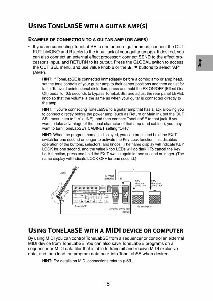
EXAMPLE OF CONNECTION TO A GUITAR AMP (OR AMPS)• If you are connecting ToneLabSE to one or more guitar amps, connect the OUT-
PUT L/MONO and R jacks to the input jack of your guitar amp(s). If desired, you can also connect an external effect processor; connect SEND to the effect pro-cessor’s input, and RETURN to its output. Press the GLOBAL switch to access the OUT SEL menu, and use value knob 6 or the ▲, ▼ buttons to select “AP” (AMP).
HINT: If ToneLabSE is connected immediately before a combo amp or amp head, set the tone controls of your guitar amp to their center positions and then adjust for taste. To avoid unintentional distortion, press and hold the FX ON/OFF (Effect On/Off) pedal for 0.5 seconds to bypass ToneLabSE, and adjust the rear panel LEVEL knob so that the volume is the same as when your guitar is connected directly to the amp.
HINT: If you’re connecting ToneLabSE to a guitar amp that has a jack allowing you to connect directly before the power amp (such as Return or Main In), set the OUT SEL menu item to “Ln” (LINE), and then connect ToneLabSE to that jack. If you want to take advantage of the tonal character of that amp (and cabinet), you may want to turn ToneLabSE’s CABINET setting “OFF.”
HINT: When the program name is displayed, you can press and hold the EXIT switch for one second or longer to activate the Key Lock function; this disables operation of the buttons, selectors, and knobs. (The name display will indicate KEY LOCK for one second, and the value knob LEDs will go dark.) To cancel the Key Lock function, press and hold the EXIT switch again for one second or longer. (The name display will indicate LOCK OFF for one second.)
USING TONELABSE WITH A MIDI DEVICE OR COMPUTERBy using MIDI you can control ToneLabSE from a sequencer or control an external MIDI device from ToneLabSE. You can also save ToneLabSE programs on a sequencer or MIDI data filer that is able to transmit and receive MIDI exclusive data, and then load the program data back into ToneLabSE when desired.
HINT: For details on MIDI connections refer to p.59.
ROUTPUTL/MONO
ToneLabSE
INPUT
Guitar
INPUT INPUTMonaural phone jack
Monaural phone jack
Guitar amp(s)Monaural phone jack
15
Playing ToneLabSE
PROGRAM SELECT MODEToneLabSE has 96 programs (24 banks x 4 programs), and every one of these programs can be totally rewritten or “custom tweaked” to your heart’s content. With the factory settings, banks 1–8 contain a total of 32 preset programs. (Banks 9–16 and 17–24 contain the same preset programs as banks 1–8.)
In order to select programs, you need to be in Program Select mode.
SELECTING A PROGRAM
As an example, here’s how to select program 2-3 (bank 2, program 3).
1. Make sure that ToneLabSE is in Program Select mode.
If the Effect On/Off pedal LED is lit, you’re in Effect On/Off mode. Press the FX ON/OFF pedal to change to Program Select mode.
2. Use the BANK UP/DOWN pedals (6.1) to select bank 2.
The bank number blinks in the bank display.
3. Press the program select 3 pedal (6.2).
Program 2-3 will be recalled instantly. The program select 3 pedal LED will light, and the bank number will also change to be steadily lit.
HINT: When you’ve selected the Bank but not the Program, the previously-selected program is still active. So if you’re playing live and your next program change requires you to switch to a different bank, you can select that bank ahead of time, ensuring a timely, seamless change.
EFFECT ON/OFF MODEYou can use program select pedals 1–4 to switch the pedal effect, modulation effect, delay effect, and reverb effect of the current program on/off individually. Also, you can use the BANK DOWN pedal to switch the signal that is being sent through the external effect processor connected to the INSERT jacks.
When you want to switch programs, press the effect ON/OFF pedal once again to return to Program Select mode.
NOTE: In Effect On/Off mode, the BANK UP pedal does nothing.
16
Intro
ducti
onPa
nel T
our
Setu
pPl
ayin
gCr
eatin
gan
d St
orin
g
SWITCHING EFFECTS ON/OFF
As an example, here’s how you can switch the pedal and insert effects on/off for the current program.
1. If the Effect ON/OFF pedal LED is dark, you’re in Program Select mode. Press the Effect ON/OFF pedal to change to Effect On/Off mode.
Program LEDs 1–4 indicate the on/off status of the pedal, modulation, delay, and reverb effects.
2. If program LED 1 is lit, the pedal effect is ON. When you press program select pedal 1, the pedal effect will turn off and LED 1 will go dark.
3. If the INSERT button LED is dark, your guitar signal is not being sent through the external effect. When you press the BANK DOWN pedal, the external effect send/return will be turned ON, and the INSERT switch LED will light.
NOTE: If you haven’t connected an external effect processor to the INSERT SEND/RETURN jacks, the INPUT signal will bypass the insert circuit whether the INSERT switch LED is lit or dark.
A/B CHANNEL HOLD
You can specify whether the channel (A or B) memorized in the program will be automatically selected when you select the program (OFF), or whether your cur-rent channel selection (A or B) will be maintained even when you select a different program(ON).
1. Press the GLOBAL button, and use the √√√√, ®®®® buttons to access the “CH HOLD” display.
2. Use value knob 6 or the ▲, ▼ buttons to change the setting.
NOTE: With the factory settings this is set to “OFF.”
17
ACTIVATING OR DEACTIVATING THE KEY LOCK FUNCTIONHere’s how you can use the Key Lock function to disable ToneLabSE’s buttons, selectors, and knobs so they can’t be accidentally changed during a live perfor-mance.
NOTE: While the Key Lock function is activated, you won’t be able to operate any controls except for the switches, pedals and the EXIT button.
NOTE: The Key Lock setting is cancelled when you turn off the power; it will be disabled when you turn on the power once again.
ACTIVATING THE KEY LOCK FUNCTION
1. If the name display shows anything other than a program name, or if the char-acters of the program name are blinking, press the EXIT button.
2. With the program name shown in the name display, press and hold the EXIT button for at least one second.
The name display will indicate KEY LOCK for one second, and then the value knob LEDs will go dark.
DEACTIVATING THE KEY LOCK FUNCTION
1. If the name display shows anything other than a program name, press the EXIT button.
2. Press and hold the EXIT button for at least one second.
The name display will indicate LOCK OFF for one second, and then the value knob LEDs will light.
18
Intro
ducti
onPa
nel T
our
Setu
pPl
ayin
gCr
eatin
gan
d St
orin
g
Creating and Storing your own ProgramsThere are two ways you can do this; by “tweaking an existing program” or by “start-ing from scratch.”
CREATING YOUR OWN PROGRAMIf you want to tweak an existing program, select one that’s close to the sound you want. Set the MODEL select switches to the amp, cabinet and effects you want to use, and use value knobs 1–6 to adjust the sound.
For example, you might start with a certain preset that has a crunchy, modern rhythm sound that you like, but create a complementary lead sound that is louder, has a bit more gain, and boosted mid-range.
Now here’s how to create your own program from scratch.
NOTE: Before you continue, make sure that the GLOBAL menu OUT SEL setting is set correctly as described in Basic Connections on p.13.
1. Select any program (p.16).
HINT: It doesn’t matter which program you select, because we’re starting from scratch.
2. In the PEDAL, MODULATION, DELAY, REVERB section, press any model select switch that is lit two times. This will turn off (bypass) all effects other than the amp model and cabinet.
3. Press the channel select switch to select the channel (A or B) whose sound you want to adjust. The LED will light green if channel A is selected, or red if channel B is selected. For this example, let’s make the LED light green to select channel A.
4. Use the AMP MODEL selector to choose the amp you want.
HINT: For details on amp types, cabinet types, and effect types, refer to “Explana-tions of the Amp, Cab and Effect Types” (p. 23).
5. Use value knobs 1–6 to adjust the GAIN, VR GAIN, TREBLE, MIDDLE, BASS, and CH VOLUME as desired. CH VOLUME adjusts the volume while preserv-ing the overall character of the sound, including the distortion of the power stage. To adjust PRESENCE, press the PRES-NR button and turn value knob 3. To return to adjusting GAIN etc., press the AMP model select button.
HINT: The key to getting the most accurate vintage tube amp distortion is to raise the VR GAIN.
NOTE: Some settings may cause your output sound to be distorted (i.e., in a way you don’t intend). If so, lower the CH VOLUME.
19
6. Use the CABINET model selector to choose the cabinet you want.
HINT: For recommended combinations of amp type and cabinet type, refer to p.34.
7. Press the PRES-NR button and adjust NR SENS (value knob 4) appropriately. Higher values of noise reduction (0.2, 0.4, ... 10.0) will produce a correspond-ingly greater effect. With a setting of “OFF” there will be no noise reduction.
NOTE: We recommend that you use noise reduction if you’re using a high-gain set-ting such as the RECTO or US HIGAIN amp type, since high gain usually gener-ates more noise. Depending on the guitar you’re using, raising the noise reduction excessively may cause some of your notes to be cut off unnaturally.
HINT: You can set noise reduction independently for channels A and B.
HINT: You can also specify a different amp or cabinet for channel B. To do so, press the channel select pedal to make the LED light red, and repeat steps 4–7.
8. In each section, choose the effect you want to use. For example if you want to add spring reverb, use the REVERB selector to select SPRING 1 (or SPRING 2).
HINT: When you do so, the reverb model will automatically be turned on, the REVERB parameter line LED of the edit section will blink, and the LEDs below the value knobs will light to indicate the REVERB parameters. For example if you’ve selected SPRING 1, value knobs 1–4 will control TIME, LO DAMP, HI DAMP, and PRE DELAY, while value knob 6 will control MIX.
9. To adjust the reverb mix amount, use value knob 6 which controls the MIX parameter.
In the same way for PEDAL, MODULATION, and DELAY effects, use the selector to choose an effect and the value knobs to adjust the parameters.
HINT: In some cases, it’s easier to adjust the PEDAL effect if modulation, delay, and reverb are not being applied. If you’re using the PEDAL effect, it’s best to make your amp and cabinet settings first, and then adjust the pedal effect before the other effects.
NOTE: For some of the models, the name of the actual parameter you will be edit-ing may differ from what is printed in the parameter line of the edit section. The name that appears in the display when you operate a value knob is the actual name. For details on parameters refer to p.35.
10. If you want to continue making adjustments, simply press the select button for the model you want to edit, and turn the value knobs.
If the EXPRESSION button lights when you operate a value knob, you have the option of assigning that parameter to an expression pedal. If you press and hold the EXPRESSION switch for at least one second, the parameter will be assigned to the expression pedal (EXP 1). (We call this the Expression Pedal Quick Assign function.) Now you can use the pedal to control that parameter while you perform. (Similarly, you can hold down the CONTROL switch to assign the parameter to expression pedal 2 (EXP 2).) For example if you set the PEDAL model selector to U-VIBE and use value knob 1 to adjust the SPEED parameter, the EXPRESSION button will light to indicate that you can use the above method to assign the SPEED parameter to the expression pedal. For details, refer to p.53.
20

Intro
ducti
onPa
nel T
our
Setu
pPl
ayin
gCr
eatin
gan
d St
orin
g
HINT: If you’ve used the PEDAL selector to select VOX WAH, the MANUAL param-eter will automatically be assigned to expression pedal 1 (EXP 1), letting you use the pedal as a wah pedal.
CHANGING THE CONNECTION ORDER OF THE EFFECTS (CHAIN)You are free to change the order in which the modulation effect, delay effect, and reverb effect are connected.
The effect connection order is saved independently for each program.
1. Press the CHAIN button, and the current connection order is displayed.
2. Use value knob 6 or the ▲, ▼ buttons to change the order.
Display Connection orderMD>DL>RV modulation→delay→reverb
MD>RV>DL modulation→reverb→delay
DL>MD>RV delay→modulation→reverb
DL>RV>M delay→reverb→modulation
RV>MD>DL reverb→modulation→delay
RV>DL>MD reverb→delay→modulation
NAMING A PROGRAM Here’s how you can name a program.
NOTE: The program name is saved as part of each program. If you switch to a dif-ferent program or turn off the power before you save, your settings will be lost.
1. Press the RENAME button.
2. Use the √√√√, ®®®® buttons to move the cursor to the character you want to change (the selected character blinks), and use value knob 6 or the ▲, ▼ buttons to change the character.
You can use the following characters.
3. Repeat step 2 to finish entering a name for your program.
4. When you’ve finished entering a name, press the EXIT button (3.7) to return to the mode you were in.
21

STORING A PROGRAMWhen your tweaking has resulted in a sound you’re happy with, store (write) it!
1. Press the WRITE button (3.6).
The name display (3.8) shows “*WRITE*” and the bank display (5.1) and pro-gram LEDs 1–4 will blink.
2. Use value knob 6 (2.2) or the ▲, ▼ buttons (3.1) to select the bank you want to use, and use the √√√√, ®®®® buttons to select the destination program (1–4).
For example if you want to store your program in 9-1 (bank 9, program 1), use value knob 6 or the ▲, ▼ buttons to make the bank display show “9,” and then use the √√√√, ®®®® buttons to make the program 1 pedal LED blink.
HINT: You can also select the store-destination program by using the BANK UP/DOWN buttons or the program 1–4 select buttons.
3. Press the WRITE button (3.6) once again.
The name display will indicate “COMPLETE.” Your program is now stored, and you’ll be back in Program Select mode.
NOTE: The program is written over the previous contents of that bank/program. The program that previously occupied the number you selected in step 2 will be erased.
NOTE: If you decide not to store your new program, press the EXIT button (3.7) to cancel the procedure.
NOTE: If you switch to a different program or turn off the power without storing the program you edited, your changes will be lost.
RESTORING A SETTING TO ITS ORIGINAL VALUE (ORIGI-
NAL VALUE)The Original Value icon in the value display (3.10) gives you a way to find out the parameter values that are stored in a program.
When you are using a knob or button to change the value of a parameter, the ORIG (original value) icon will appear when the value you are adjusting matches the “original value” stored in the program.
HINT: So, you’re flipping through the programs on your new ToneLabSE, and you come across one you really like. It’s easy to find out exactly what settings are dialed in to get such an awesome tone — just use this Original Value display fea-ture!
22
AMP
TYPE
CABI
NET
TYPE
PEDA
LMO
DULA
TION
DELA
YRE
VERB
Amp/
Effe
ct
Explanations of the Amp, Cabinet and Effect Types
his section explains ToneLabSE’s sixteen amp models, sixteen pedal effects, eleven cabinet models, modulation, delay, and reverb effects.
A. AMP MODELSWhich amps did we painstakingly model for our seductive selection of 16? Believe me when I say it wasn’t easy ‘cos, as I’m sure you know, there’s a plethora of great sound-ing amps out there. After countless hours of soul searching, earnest discussions (not to mention the occasional friendly argument!), calls to tone-wise friends (some profes-sional players, some not...but all blessed with great ears) plus, of course, listening and playing, a top 16 list was finally drawn up. As you’re about to discover, the ones we went with are not only the cream of the crop but also offer up the widest possible array of the greatest guitar tones known to man - from pristine clean to outrageous over-drive and all points in-between. First though, some stuff you should know...
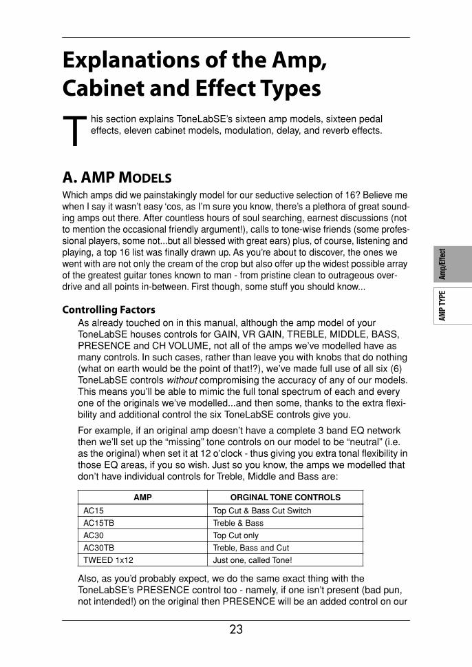
Controlling FactorsAs already touched on in this manual, although the amp model of your ToneLabSE houses controls for GAIN, VR GAIN, TREBLE, MIDDLE, BASS, PRESENCE and CH VOLUME, not all of the amps we’ve modelled have as many controls. In such cases, rather than leave you with knobs that do nothing (what on earth would be the point of that!?), we’ve made full use of all six (6) ToneLabSE controls without compromising the accuracy of any of our models. This means you’ll be able to mimic the full tonal spectrum of each and every one of the originals we’ve modelled...and then some, thanks to the extra flexi-bility and additional control the six ToneLabSE controls give you.
For example, if an original amp doesn’t have a complete 3 band EQ network then we’ll set up the “missing” tone controls on our model to be “neutral” (i.e. as the original) when set it at 12 o’clock - thus giving you extra tonal flexibility in those EQ areas, if you so wish. Just so you know, the amps we modelled that don’t have individual controls for Treble, Middle and Bass are:
Also, as you’d probably expect, we do the same exact thing with the ToneLabSE’s PRESENCE control too - namely, if one isn’t present (bad pun, not intended!) on the original then PRESENCE will be an added control on our
AMP ORGINAL TONE CONTROLS
AC15 Top Cut & Bass Cut Switch
AC15TB Treble & Bass
AC30 Top Cut only
AC30TB Treble, Bass and Cut
TWEED 1x12 Just one, called Tone!
T
23

model. This time though, the “neutral” position is when the control is all the way off (turned fully counterclockwise). The two models this applies to are BLACK 2x12 and TWEED 1x12.
IMPORTANT NOTE: As you’ll discover when you read their descriptions, in the case of the AC15, AC15TB, AC30 and AC30TB models, we’ve utilized the PRESENCE control to mimic the TOP CUT control - whether it was present on the original or not.
About the Gain and Volume knobsToneLabSE’s amp models provide three programmable knobs that affect the volume (gain); GAIN, VR GAIN, and CH VOLUME. Each control does has its own specific job, and the sound of a particular amp model can vary over an amazingly wide range just depending on the settings of these knobs. As some of you will know, most vintage amps only have one VOLUME control to set up the sound, whilst more modern amps usually have two types of level controls – GAIN (or sometimes PREAMP VOLUME) that controls the input level of the preamp section, and MASTER VOLUME that controls how much signal is (and how loud it is going to be) passed from the preamp to the power amp. With many vintage amps there is no MASTER VOLUME, the preamp feeds directly into the power amp without any type of control.
The ToneLabSE’s controls are designed to cover all these points:
ToneLabSE GAIN: On vintage type models that do not have a master volume (i.e., AC15, AC15TB, AC30, AC30TB, UK BLUES, UK 68P, BLACK 2x12, TWEED 1x12, TWEED 4x10), the GAIN control works like the VOLUME of the original amp. On other model amps that do have a master volume, the GAIN control works like GAIN or PREAMP VOLUME.
ToneLabSE VR GAIN: MASTER VOLUME that controls how much preamp sig-nal level is passed to the power amp, which in our case is the VALVE REAC-TOR stage. (Your ToneLabSE works like a real amp.)
ToneLabSE CH VOLUME: For want of a better way of putting it, this is like a power attenuator that you would add between the output of your amp and the input of your speaker cabinet. This controls the level of the final mix and allows you to balance all your programmed amp sounds to each other.
As in how the original amps work, we have made the relationship between preamp and power amp work in the same way. Therefore to obtain truly authentic tones please use the VR GAIN control in the same way, i.e. with VIN-TAGE type models that do not have Master Volume control’s, turn the VR GAIN control up to maximum. When using a model of a modern amp that does have a master volume con-trol, adjust VR GAIN just as you would adjust the master volume control. Low settings of VR GAIN will tend to produce more of a preamp distortion, while high settings will add the distinctive distortion and warmth of the Valve Reactor.
Lastly, if an original amp features a unique switch or control we make sure that we cover it! Such things will be revealed in the model descriptions that follow shortly...
Tube TalkUs Brits call ‘em valves while our US cousins call ‘em tubes...as the saying goes: England and America are merely two countries divided by a common
24
AMP
TYPE
CABI
NET
TYPE
PEDA
LMO
DULA
TION
DELA
YRE
VERB
Amp/
Effe
ct
language! Anyway, call ‘em what you will, these wondrous glass bottles lie at the tonal heart of each of our 16 models. As all the amps we’ve modelled hail from one of the two countries just mentioned, in honour of their heritage, the descriptions of all English amps will employ the words “valve” and “valves,” while the American ones will be tubular!
Power Amp AccuracyWhat happens in the power stage of any good tube amp is of paramount impor-tance to the way the amp sounds, feels and behaves. The way the power amp operates (Class A or Class AB), the power tubes used (EL84s, EL34s, 6L6s, 6V6s), the exact nature of the negative feedback loop circuitry (if one even exists) and how the power stage interacts (a relationship called damping) with the speaker(s) it is driving - all these things play a vital role in the creation of tone. That is why we have fitted your ToneLabSE with our patented Valve Reactor Technology – a modelling breakthrough that is unique to VOX and infuses our critically acclaimed Valvetronix range of amps with life and feel. This revolutionary technology emulates a tube power-amp by using real tubes in a real tube amp circuit and ensures that all the important bases inherent in a tube amp are faith-fully and accurately covered. For example: if you choose amp model AC30TB - an amp with a Class A power stage, EL84 output tubes and no negative feed-back, that’s exactly what your Valve Reactor power amp reconfigures itself to be.
This all said, let’s take a look at each of our amp models...
1. AC15This is modelled on Channel 2 of an amazing sounding 1962 VOX AC15,
which is part of our vast amp collection. This 1x12", 15 Watt, valve driven, dual chan-nel combo was unleashed on the market in 1958 and was the first ever VOX ampli-fier. The reason for it being named the AC15 is simple: AC stands for Amplifier Combination, while 15 indicates the Wattage. Thanks to its compactness, power, built in tremolo/vibrato effects (on Channel 1 only) and tremendous tone, this combo was a huge hit with the popular British guitar bands of the time, including several chart topping acts, the majority of whom were only too happy to endorse Vox.
One of the biggest reasons for the unique, signature tone of this amp is the fact that it employs EL84 output valves in a Class A circuit with no negative feedback. This is also true of the other three VOX amps, we’ve modelled - the AC15TB, AC30 and AC30TB. In a nutshell, the result of this design is more power and more distortion - the latter of which gets thick with second and third order harmonics that become more and more prev-alent as the amp is cranked. Thanks to our unique Valve Reactor Technology the power stage of your ToneLabSE is automatically switched to its “EL84s in a Class A circuit with
QUESTION: What’s the difference between an ECC83 preamp valve and a 12AX7 preamp tube?
ANSWER: Nothing! They’re the same exact thing – namely the most popu-lar preamp tube in ampland. ECC83 is the British name, 12AX7 (a.k.a. 7025) is the American. See, I told you we were two countries divided by a common language!
25
no feedback” emulation whenever AC15, or any of the other three Vox models, is chosen.
Like most amps of its era, the AC15 is the very essence of simplicity. In fact, the Channel we modelled, Channel 2 (remember!?), only has three controls - Volume, Brilliance (really a bass cut) and Top Cut. When you select AC15, the ToneLabSE’s GAIN control mimics the original’s Volume control, while the PRES-ENCE control acts as the Top Cut.* FYI, the AC15’s Top Cut control affects the high frequencies in a very different way than a “regular” Treble control. Deft use of it will help you dial in the exact amount of that instantly recognizable, world-famous VOX “sparkle.” The BASS control acts as the Bass Cut (Originally labelled Bril-liance) with total variability instead of the Original two position switch.
As for what the “extra” TREBLE and MIDDLE controls on our AC15 model do: as already mentioned earlier, they’re exactly that - “extra!” Set them at 12 o’clock and they’re “neutral” (i.e. they mimic the exact tone of the original) or tweak them for extra tonal flexibility.
*CONTROL NOTE: The original AC15’s Top Cut control works in the opposite way you’d expect - it “cuts” when you turn it up! You’ll be glad to read that our model of the Top Cut control (the PRESENCE knob) works in a much more logical fashion - turn it up for more “sparkle,” turn it down for less.
Original’s valve compliment: 1 x EF86, 3 x ECC83s, 1 x ECC82 in the preamp, 1 x EZ81 rectifier, 2 x EL84s in the power amp.
2. AC15TBWhile the AC15 was born in the late ’50s, the AC15TB is a modern-day child of the ’90s which combines the sweet “n” desirable tonal characteristics of the AC15’s low Wattage power stage, with the increased tonal flexibility that the Top Boost (TB) channel of an AC30 has to offer. Then, to sweeten the pot even further, a 12" Celes-tion “Blue” speaker (what else?), Reverb and a Master Volume control were thrown in too. The result is a highly flexible 15 Watt, all-valve, 1x12 combo that successfully marries the pureness of great vintage VOX tone with modern features.
The original has two tone controls - Treble and Bass. So, as is the norm, the ToneLabSE’s TREBLE and BASS controls mimic their namesakes while the MIDDLE (“neutral” at 12 o’clock) and PRESENCE add further tonal flexibil-ity...should you want it. To ensure maximum “Voxiness,” we’ve made sure that the PRESENCE control behaves exactly like the “Top Cut” on the original AC15 - except in reverse (“off” = cut) to make it more logical, just like on our AC15 model.
In trademark VOX fashion, our AC15TBX model oozes clean tones that “jangle” and “chime,” while its overdrives are smooth yet pulsating with desirable harmonic overtones. Enjoy!
Original’s valve compliment: 5 x ECC83s in the preamp, 1 x 5Y3GT rectifier, 2 x EL84s in the power amp.
3. AC30As already stated, the VOX AC15 was a huge hit with the British guitar bands of the late ’50s. However, as the popularity of the AC15 using bands grew, so did their need for a more powerful amp. Sure, the AC15 was loud for a 15 Watt amp -
26
AMP
TYPE
CABI
NET
TYPE
PEDA
LMO
DULA
TION
DELA
YRE
VERB
Amp/
Effe
ct
darned loud in fact - but it was no match for 1,000 + screaming fans! Remember folks, back in the late ’50s/early ’60s, guitar amps weren’t being fed through the PA - that was reserved purely for vocals, the band’s back-line had to do the rest. Clearly VOX needed to come up with a louder amp and the company was only too happy to rise to the challenge...
The fruit of VOX’s labour was unveiled to the world in 1959 - the 30 Watt, 2x12, AC30. Several top British bands graduated up to the AC30 instantly and, within months, one of them had scored a number one single with a stirring guitar instrumental. Not surprisingly, pretty much every other UK act worth its salt immedi-ately followed suit and the AC30 became the amp behind the so-called “Beat Boom” of the time. More importantly, it also became the driving force behind the now leg-endary “British Invasion” - the name given to the huge wave of success that several English bands enjoyed in America during the ’60s. This charge was led by a quartet hailing from Liverpool who quickly became VOX’s most famous ambassadors ever.
We’ve modelled the sterling sounds of the AC30’s Normal channel as they defi-nitely encapsulate those classic tones that defined the aforementioned British invasion. Just like its smaller brother, the AC15, the AC30’s Normal channel boasts the bare mini-mum of knobs - Volume and Top Cut (modelled by GAIN and PRESENCE* respectively).
*CONTROL NOTE: Once again, our PRESENCE control models the “Top Cut” on the original AC30 exactly - except in reverse (“off” = cut) to make it more logical, just like on our AC15 model.
Original’s valve compliment: 4 x ECC83s, 1 x ECC82 in the preamp, 1 x GZ34 rectifier, 4 x EL84s in the power amp.
4. AC30TBEven though the AC30 was a runaway success, several artists expressed a desire for the amp to have more tonal flexibility and a pinch of extra gain too. VOX reacted quickly and came up with some clever extra tone circuitry that featured an additional ECC83 valve and was called “Top Boost.”* When “Top Boost” was added to an AC30 it increased the gain of the combo’s Brilliant channel, and added two extra EQ controls, giving the amp three tone controls -Treble, Bass and Cut. To say it was an instant hit with the guitar play-ing public would be a gross understatement! In fact, its gutsy tone became an instantly recognisable signature sound of many major groups in the mid ’60s.
NERDY HISTORICAL NOTE: VOX initially called this their “Brilliance Unit” but it quickly became known as “Top Boost.” When Top Boost was first introduced it was only available as a retrofit assembly. Even though this modification was not particu-larly difficult to add, it was beyond most folk (hey, I don’t know about you, but mess-ing around with electricity is hardly my idea of fun!). Consequently, in 1964, Top Boost was fitted to the AC30 as standard.
Once again, the PRESENCE control of our model acts as the original’s Cut (but in reverse: “off” = cut) while the GAIN, TREBLE and BASS mimic the original’s Volume, Treble and Bass controls. The MIDDLE is an “extra” with 12 o’clock being its “neutral” position.
Our AC30TB model produces clean sounds that are rich and jangly with a smooth yet detailed top end, and overdrives that have a glorious, throaty bark - just like those classic, “Class A” tones that have made the original a “must have” in any serious player’s amp collection.
27
Original’s valve compliment: 5 x ECC83s & 1 x ECC82 in the preamp, 1 x GZ34 rectifier, 4 x EL84s in the power amp.
5. UK BLUESOur UK BLUES model is based on the “High Treble” channel of an extremely rare, hand-wired head made in jolly old England in the early ’60s. Although the TWEED 4x10 circuit was used as a basic template for this amp, several fundamental changes (e.g. different tubes, different transformers, a higher output impedance and vastly different speakers in a closed-back cab), give UK BLUES its own unique and highly desirable character. Indeed, when cranked-up this 30 Watt baby produces a crunch that forever changed the sound of rock “n” roll - which is why it is still highly revered to this very day.
Original’s valve compliment: 3 x ECC83s in the preamp, 1 x GZ34 rectifier, 2 x KT66s in the power amp.
6. UK 68PThis is based on the “High Treble” channel of a 1968, 50 Watt, all-valve head, boast-ing a Plexiglas front panel and four (4) inputs. The no-nonsense original doesn’t fea-ture a Master Volume control so the best and, arguably, only way to set it up is to max out the volume and let rip! And, that’s exactly what everyone did - and still does! This amp was chosen because the tone was incredibly rich and warm, instant clas-sic heaven! As this amp has no master volume facility, the only, and greatest, way of using it to its full potential was to wind the volume up to maximum.To achieve the same response as the original, remember to turn the VR Gain control to maximum. The ToneLabSE works EXACTLY like the original. This goes for all non-master type amp models.
So, wind the GAIN control all the way up and immerse yourself in an instantly recognizable, organic overdrive that responds beautifully to the subtle dynamics of your playing and dominates “classic rock.” Rolling back your guitar’s volume control results in a unique and highly useable clean sound.
Original’s valve compliment: 3 x ECC83s in the preamp, 2 x EL34s in the power amp.
7. UK ’80S
This is modelled on a 1983, all tube, single channel 100 Watt head that boasts a Master Volume control - a wonderful feature that allows the user to dial in a decent crunch tone without having to max out the amp’s volume. Invariably played with it’s (preamp) Gain control cranked to the max, this amp was responsible for the fat, roar-ing sound that dominated ’80s hard rock and heavy metal. Yes sir, from spandex clad Europeans who rocked like hurricanes, to American speed freaks who rode the light-ning and reigned in blood, UK ’80s was the only amp of choice...and, for many, still is!
Although UK ’80s became famous for it’s distinctive, cranium-crushing crunch, it isn’t merely a “one trick pony” and neither is our model - just like the original, when you roll back your guitar’s volume knob you’ll get a bright, clean sound that’s perfect for chord work and will cut through any mix like a hot knife through butter.
28
AMP
TYPE
CABI
NET
TYPE
PEDA
LMO
DULA
TION
DELA
YRE
VERB
Amp/
Effe
ct
Original’s valve compliment: 3 x ECC83s in the preamp, 4 x EL34s in the power amp.
8. UK ’90S
This model is based on the “lead” channel of a 100 Watt, dual channel head that is capable of so much preamp distortion it houses a Gain control that goes all the way up to a Nigel Tufnel approved “20, dunnit!” This amp replaced UK ’80s and was developed to satisfy the ever-evolving rock guitarists’ insatiable lust for more gain, features and flexibility. Was this amp popular? Judging by the fact it quickly became the “industry standard” for the decade in question, the answer is a resounding “yes!”
Original’s valve compliment: 4 x ECC83s in the preamp, 4 x EL34s in the power amp.
9. UK MODERN (UK MODRN)This is modelled on the High Gain channel of a modern, all-tube 100 Watter that is effectively a hybrid of the UK ’80s and UK ’90s amps. It combines the toneful high gain preamp stage and modern features of UK ’90s with the unmistakable, “snarling” punch and girth the UK ’80s power stage had to offer. The result is a highly aggres-sive, tone-breathing monster capable of mondo-gain while retaining individual note definition. With the GAIN control on full, UK MODERN allows lead lines to soar into soulful feedback, while its low-end “chunk” remains tight and punchy. Wimps beware!
Original’s valve compliment: 4 x ECC83s in the preamp, 4 x EL34s in the power amp.
10. RECTOThis bad boy is based on the “Modern High Gain” channel of a brutal, 100 Watt, armour-plated beast hailing from California. Its deep, dark, loose low-end, some what “fizzy” top and Monster-like gain has made this all-tuber a mainstay for many modern, metal acts who either tune their guitars down as low as they can possibly go, or wield 7-string axes.
At low GAIN settings, RECTO produces a distinctive, bright clean sound bolstered by some rich, upper harmonics that add fullness and dimension. This said, RECTO is definitely not recommended for Country “n” Western picking. But, if you play slamming, “nu-metal” that’s tuned lower than whale droppings, then RECTO could well be the only way to go!
Original’s tube compliment: 5 x 12AX7s in the preamp, 2 x 5U4G rectifier tubes, 4 x 6L6s in the power amp.
11. US HIGAIN (US HI-G)This is modelled on the Overdrive Channel of an all-tube, 100 Watt head built in 1991 and covered in snakeskin! This high gain, power house was designed by a guy who also builds and drives Hot Rod cars so it should come as no surprise that the originals controls all go to eleven - after all, “that’s one louder innit!” (© Nigel Tufnel!)
US HIGAIN is capable of a powerful, heavily saturated sound that com-bines an open low-end with compressed mids and highs. The result is a tone that
29

remains focused and well defined at even the most extreme gain settings. These attributes have made this head a favourite with several of the world’s leading play-ers, and its versatility make it ideal for a wide variety of purposes and styles.
Original’s tube compliment: 4 x 12AX7s in the preamp, 4 x 6L6s in the power amp.
12. BOUTIQUE OD (BTQ OD)For this one we modelled the Overdrive channel of a very rare, very expensive and very respected 100 Watt head named the Overdrive Special. This custom-order, hand-wired beauty has a spectacular overdriven sound that’s perfect for sax-like, legato soloing. With its GAIN control wide-open, BOUTIQUE OD produces a stun-ning sustain which is very smooth and very soulful - can you say “woman tone!?”
Original’s tube compliment: 3 x 12AX7s in the preamp, 4 x EL34s in the power amp.
13. BOUTIQUE CL (BTQ CL)For this amp type, we modelled the Clean channel of another very expensive, hand-wired, custom amp made by the same boutique builder as BOUTIQUE OD. We audi-tioned several top-shelf boutique amps for this model but this amp was the clear win-ner. Even though its garish, fuzzy red covering wasn’t to everyone’s taste, it’s beautiful clean sound was! Its beautifully rounded low-end, delightfully transient mid-range attack and sweet treble make it the perfect partner for single-coil pickups. It is also incredibly responsive and extremely sensitive to picking styles and pickup selection. And, as an added bonus, strummed chords just ring out and blossom.
Original’s tube compliment: 3 x 12AX7s in the preamp, 4 x 6L6s in the power amp.
14. BLACK 2X12 (BLK 2X12)The dual channel, blackfaced beauty we modelled here is considered a “must-have” 2x12 combo for country and blues players, and rightfully so - after all, its cel-ebrated clean sound is very tight “n” twangy, with a deep, taut, piano-like bass.
Pristine clean tones aside, BLACK 2x12 is also capable of producing that classic Chicago blues tone - especially with single coil pickups. In keeping with the original, when pushed hard the bass on our model tends to crumble. So, to emu-late this classic, BLACK 2x12 overdrive, here’s what you dial in on your ToneLabSE: full GAIN and VR GAIN, not much BASS, full MIDDLE and set TRE-BLE to taste. Because the EQ network of BLACK 2x12 lies before the main gain stage of its preamp y’see, pushing the mids in this way emphasizes the distortion in that frequency range and the result is a lovely, singing blues tone.
As already mentioned elsewhere, the original amp doesn’t have a Pres-ence control but does have a Bright Switch. The PRESENCE control on your ToneLabSE emulates this switch when “off” and “on,” plus all points in-between!
Original’s tube compliment: 4 x 12AX7s & 2 x 12AT7 (a.k.a. ECC81) in the preamp, 4 x 6L6s in the power amp.
30
AMP
TYPE
CABI
NET
TYPE
PEDA
LMO
DULA
TION
DELA
YRE
VERB
Amp/
Effe
ct
TONAL HINT: BLACK 2x12 is the perfect partner for ACOUSTIC (Acoustic Guitar Simulator) in the Pedal section.
15. TWEED 1X12 (TWD 1X12)The original we modelled here was born in Fullerton, California, in 1958, and clad in “tweed” - hence its name! Just like the AC15, this 18 Watt, 1x12, all-tube combo is the very essence of simplicity. Aside from the obligatory Volume knob, it only housed one other knob - a single Tone control creatively named (wait for it!) Tone! This Tone control is merely a treble cut and boost, and its behaviour can be mimicked by using the Valvetronix’s TREBLE, MIDDLE and BASS EQ network as follows:
Original Tone control turned all the way down (off) = BASS on full; TREBLE and MIDDLE at 9 o’clock (PRESENCE “off”).
Original Tone control turned up “full” (on 10) = TREBLE on full; MIDDLE and BASS at 9 o’clock (PRESENCE “off”).
NOTE: As the original doesn’t have a Presence control, PRESENCE is “neutral” when “off,” but can be used to add “extra” sparkle and cut to the model if you so wish.
In keeping with the original, the TWEED 1x12 produces an open, relatively unco-loured sound when clean, but starts to “snarl” beautifully when pushed into overdrive. Its highly desirable “snarl” is rich with harmonic content and cranking this puppy up will produce those classic, old rockabilly and rock “n” roll sounds of the ’50s and ’60s, at the drop of a 10 gallon hat - especially when a single coil pickup is used.
Original’s tube compliment: 1 x 12AY7, 1 x 12AX7s in the preamp, 1 x 5Y3GT rectifier, 2 x 6V6s in the power amp.
16. TWEED 4X10 (TWD 4X10)The 4x10 combo we modelled here was built in 1959 and originally intended for bass guitar. This said, six-stringers were quick to embrace its smooth-yet-cutting overdrive which is perfect for R&B (rhythm “n” blues) guitar. TWEED 4x10 is also very sensitive and responsive to both picking strength and the volume setting on your guitar. This means that by backing-off your axe’s volume when the amp is cranked, you can produce a beautifully clean and full tone. It also means that dynamic picking control allows you to make notes or chords more distorted or clean than others, depending on how hard or how soft you pick ‘em.
Another cool tonal quirk of TWEED 4x10 is the classic, vintage tube amp sag its GZ34 rectifier tube adds to your notes whenever the amp is driven really hard. “What is sag?” Do I hear you ask? Well, crank the Gain and VR GAIN controls on this model, dig in hard with your pick and you’ll soon find out! Can you hear how the note literally “sags” when you first hit it and then it opens up? That’s sag, geddit?
TONAL NOTE: Just like on the original, the Middle and Treble control of TWEED 4x10 are highly interactive and high settings of the Middle control automatically add treble to your sound. As a result, you may want to turn down the Treble control as a counter measure. Conversely, low Middle settings reduce treble so you might want to crank the Treble a little more in such instances.
Original’s tube compliment: 1 x 12AY7, 2 x 12AX7s in the preamp, 1x GZ34 rectifier, 2 x 5881s in the power amp.
31
B. CABINET MODELSNow let’s look at the CABINET models:
CABINET AND SPEAKER ACCURACYThere’s not much point in having incredibly accurate amp models if the speaker cabinet models on offer aren’t of the same exacting standards. As you may know, in real life, the output stage of a tube amp works in close harmony with the varying impedance curve of the speaker(s) it is driving. This intimate and vital relationship plays a major role in producing the warm, punchy sound and pleasing feel that we all know and love. In a nutshell, modelling a speaker cabinet is not just a case of frequency response, but is a combination of fre-quency response, transient response (how a speaker reacts to the strength of how a note is played), and the all-important interaction of the amps output to the speaker’s impedance curve. In addition, other vitally important factors that have to be taken into account when modelling a cabinet are the actual physical dimensions of the enclosure (cabinet), the unique tonality of said enclosure (which will be affected by both the type and thickness of the wood it is made of) and whether it boasts an open, semi-open or closed-back design. Special cir-cuitry and unique modelling technology ensures that all of these factors are well taken care of in the cabinet models built into your ToneLabSE.
1. TWEED 1X8 (TWD 1X8)The 8-inch 3.2-ohm Alnico speaker in this cabinet model is the one built into a sim-ple amp with a 6V6 output valve. You’ve no doubt heard the sound of this amp, but you might not have noticed what kind of amp it really is. Although you wouldn’t guess from the size of the speaker itself, the sound has an amazingly broad range. The lows are deep and warm, and the highs are clean and sparkling, yet it does not have that irritating sound typical of the 8-inch speakers often used for guitar.
2. TWEED 1X12 (TWD 1X12)This speaker is the other half of our Tweed 1x12 Amp model. As the name sug-gests it is a single 12" speaker, uses an Alnico magnet and made in the USA by one of the US’s revered names in vintage loudspeakers.
3. TWEED 4X10 (TWD 4X10)Keeping with the US made Alnico magnet speakers, this cabinet partnered our TWEED 4x10 modelled amp. It is an open backed cab using four 10" 8 Ohm speakers, wired in parallel for a total of 2 Ohms impedance. Although originally intended for bass guitar, this speaker rocks for many different styles.
4. BLACK 2X10 (BLK 2X10)Although we did not model the amp that goes exactly with this cabinet, we loved the tone of this mid-60s Fullerton, California made open backed 2x10" ceramic magnet (of US origin) 35 Watt combo. So here it is. Great for blues, jazz and coun-try. As with all cabinet models it can be mixed and matched with any amp model to
32
AMP
TYPE
CABI
NET
TYPE
PEDA
LMO
DULA
TION
DELA
YRE
VERB
Amp/
Effe
ct
produce some interesting tonal combinations. But for some recommended uses, please see the following charts.
5. BLACK 2X12 (BLK 2X12)As you’ve probably guessed by now, this speaker system accompanied the amp that was modelled for the BLACK 2x12 amp. Featuring two 12" Ceramic magnet speak-ers, again made in USA in the mid ’60s. They are 8 Ohm units wired in parallel for a 4 Ohm total load. These speakers have been featured on countless recordings of many styles of music, but very predominantly Country and Blues based Rock.
6. VOX AC15 (AC15)This is a 1x12" open backed combo using the famed VOX Blue Alnico speaker, manufactured by Celestion in Ipswich, England. The one we used was a modern re-issue that was housed in the VOX AC15TB combo. This speaker, which is 8 Ohms impedance, 15 Watts power handling, is amazingly full-bodied for a 1x12 open back cab, and, of course, helps bring the famous VOX chime to the forefront.
7. VOX AC30 (AC30)Obviously, double the power – double the speakers. 2x12" VOX Blue Alnicos, wired in series for 16 Ohms, adds even more of that great VOX tone. This time we modelled some great sounding originals from way back in the ’60s. As speakers get old their tone changes, so this configuration adds a different slant on how these speakers sound.
8. VOX AD412 (AD412)This cabinet is one of VOX’s latest products, and due to the fact we are extremely proud of it, and that it is without a doubt an exceedingly great sounding cabinet, we just had to include it with our cabinet models. The cabinet itself features custom designed Celestion speakers using Neodymium magnets, one of the first, if not the first, cabinet to use this technology. It also uses some special cabinet acoustic design technology that is also a first for VOX and 4x12s in general. Use it as a valid tonal option with any model, but especially the amp head models. We think you will like it!
9. UK H30 4X12 (UK H30)This is an older, heavy-duty cabinet (with 30 Watt speakers, from the late ’60s) made by the same famous UK amp company as the UK T75 4x12. Many of these cabinets have been used on countless classic rock recordings throughout the past.
10. UK T75 4X12 (UK T75)This 4x12" model is of a famous, UK built, black box loaded with modern, 75 Watt Brit-ish speakers. Normally seen stacked, this is probably the biggest selling guitar cabinet ever and is eminently suitable for most rock styles. How could we not model it?!
11. US V30 4X12 (US V30)This black beast of a cabinet hails from the same home in California as our RECTO amp. It uses four UK made “Vintage” named speakers.
33
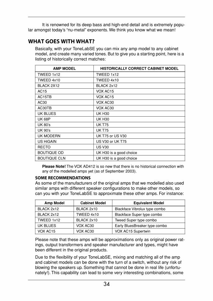
It is renowned for its deep bass and high-end detail and is extremely popu-lar amongst today’s “nu-metal” exponents. We think you know what we mean!
WHAT GOES WITH WHAT?Basically, with your ToneLabSE you can mix any amp model to any cabinet model, and create many varied tones. But to give you a starting point, here is a listing of historically correct matches:
Please Note! The VOX AD412 is so new that there is no historical connection with any of the modelled amps yet (as of September 2003).
SOME RECOMMENDATIONSAs some of the manufacturers of the original amps that we modelled also used similar amps with different speaker configurations to make other models, so can you with your ToneLabSE to approximate these other amps. For instance:
Please note that these amps will be approximations only as original power rat-ings, output transformers and speaker manufacturer and types, might have been different in the original products.
Due to the flexibility of your ToneLabSE, mixing and matching all of the amp and cabinet models can be done with the turn of a switch, without any risk of blowing the speakers up. Something that cannot be done in real life (unfortu-nately!). This capability can lead to some very interesting combinations, some
AMP MODEL HISTORICALLY CORRECT CABINET MODEL
TWEED 1x12 TWEED 1x12
TWEED 4x10 TWEED 4x10
BLACK 2X12 BLACK 2x12
AC15 VOX AC15
AC15TB VOX AC15
AC30 VOX AC30
AC30TB VOX AC30
UK BLUES UK H30
UK 68P UK H30
UK 80’s UK T75
UK 90’s UK T75
UK MODERN UK T75 or US V30
US HiGAIN US V30 or UK T75
RECTO US V30
BOUTIQUE OD UK H30 is a good choice
BOUTIQUE CLN UK H30 is a good choice
Amp Model Cabinet Model Equivalent Model
BLACK 2x12 BLACK 2x10 Blackface Vibrolux type combo
BLACK 2x12 TWEED 4x10 Blackface Super type combo
TWEED 1x12 BLACK 2x10 Tweed Super type combo
UK BLUES VOX AC30 Early BluesBreaker type combo
VOX AC15 VOX AC30 VOX AC15 Supertwin
34
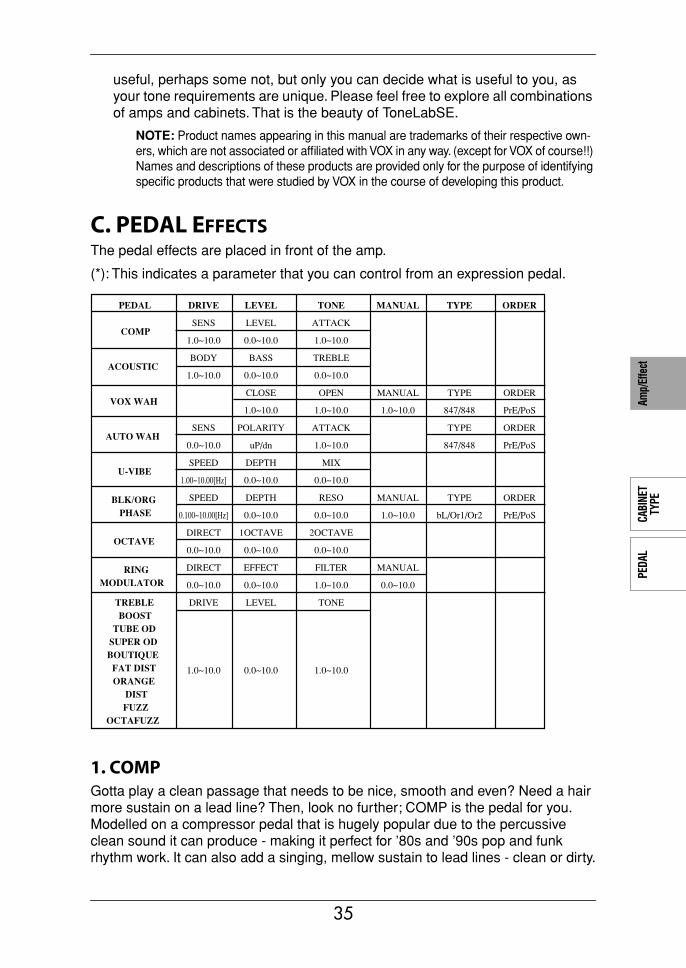
AMP
TYPE
CABI
NET
TYPE
PEDA
LMO
DULA
TION
DELA
YRE
VERB
Amp/
Effe
ct
useful, perhaps some not, but only you can decide what is useful to you, as your tone requirements are unique. Please feel free to explore all combinations of amps and cabinets. That is the beauty of ToneLabSE.
NOTE: Product names appearing in this manual are trademarks of their respective own-ers, which are not associated or affiliated with VOX in any way. (except for VOX of course!!) Names and descriptions of these products are provided only for the purpose of identifying specific products that were studied by VOX in the course of developing this product.
C. PEDAL EFFECTSThe pedal effects are placed in front of the amp.
(*): This indicates a parameter that you can control from an expression pedal.
1. COMPGotta play a clean passage that needs to be nice, smooth and even? Need a hair more sustain on a lead line? Then, look no further; COMP is the pedal for you. Modelled on a compressor pedal that is hugely popular due to the percussive clean sound it can produce - making it perfect for ’80s and ’90s pop and funk rhythm work. It can also add a singing, mellow sustain to lead lines - clean or dirty.
PEDAL DRIVE LEVEL TONE MANUAL TYPE ORDER
SENS LEVEL ATTACKCOMP
1.0~10.0 0.0~10.0 1.0~10.0
BODY BASS TREBLEACOUSTIC
1.0~10.0 0.0~10.0 0.0~10.0
CLOSE OPEN MANUAL TYPE ORDERVOX WAH
1.0~10.0 1.0~10.0 1.0~10.0 847/848 PrE/PoS
SENS POLARITY ATTACK TYPE ORDERAUTO WAH
0.0~10.0 uP/dn 1.0~10.0 847/848 PrE/PoS
SPEED DEPTH MIXU-VIBE
1.00~10.00[Hz] 0.0~10.0 0.0~10.0
SPEED DEPTH RESO MANUAL TYPE ORDERBLK/ORGPHASE 0.100~10.00[Hz] 0.0~10.0 0.0~10.0 1.0~10.0 bL/Or1/Or2 PrE/PoS
DIRECT 1OCTAVE 2OCTAVEOCTAVE
0.0~10.0 0.0~10.0 0.0~10.0
DIRECT EFFECT FILTER MANUALRINGMODULATOR 0.0~10.0 0.0~10.0 1.0~10.0 0.0~10.0
DRIVE LEVEL TONETREBLEBOOST
TUBE OD SUPER ODBOUTIQUE
FAT DISTORANGE
DISTFUZZ
OCTAFUZZ
1.0~10.0 0.0~10.0 1.0~10.0
35
2. ACOUSTICWanna go “unplugged” without the hassle of switching guitars and amps? Enter the acoustic guitar simulator - a clever effect that magically converts an electric guitar’s sound into that of an acoustic. It works best with a single coil (read: low output) pickup in the neck position, especially when paired with the BLACK 2x12 amp model.
3. VOX WAHThis effect is modeled on two legendary VOX wah pedals; the V847 and the V848 Clyde McCoy model. Thanks to their unique “throaty” tone, these are the only wah pedals many professionals will consider stepping on. When used wisely, this pedal can either make your guitar cry like a baby or howl like a man possessed!
USEFUL TONE HINT: A great tonal trick that’s employed by many guitarists, including some who are household names, is to find a “sweet spot” within the range of their Wah pedal and then leave it there. This is often called stuck-Wah (imagine that!) and, when used tastefully, can be very effective as it produces a very distinc-tive sound that will cut through any mix. You can dial in a stuck-Wah “sweet spot” with your TONE control in a heartbeat. Try it, it’s cool...
4. AUTO WAHThe lazy man’s Wah pedal! Only kidding...this quirky but useful effect allows you to create an automatic “Wah” effect that varies with your picking dynamics (i.e. how hard or soft you hit the strings). As in VOX WAH, you can select either V847 or V848 as the wah type.
[1] “SENS” 1.0...10.0 Adjusts the sensitivity of the compressor (i.e. when its “smoothing” effect kicks in). The amount of compression/sustain will increase the more you turn this control up.
[2] “LEVEL” 0.0...10.0 Adjusts the output level.[3] “ATTACK” 1.0...10.0 Adjusts the strength of the attack.
[1] “BODY” 1.0...10.0 Adjusts the body resonance. You’ll need to adjust the BASS along with this parameter to keep a balance.
[2] “BASS” 0.0...10.0 Adjusts the bass.[3] “TREBLE” 0.0...10.0 Adjusts the treble.
[2] “CLOSE” 1.0...10.0 Adjusts the tone when the wah pedal is closed.[3] “OPEN” 1.0...10.0 Adjusts the tone when the wah pedal is open.[4] “MANUAL” 1.0...10.0 * Adjusts the openness (position) of the wah.[5] “TYPE” 847, 848 Selects either V847 or V848 Clyde McCoy model as the
wah type[6] “ORDER” PrE(PRE),
PoS(POST)Selects the connection order. PRE/POST connects the wah before/after the Amp Model.
[1] “SENSE” 0.0...10.0 * Adjusts the sensitivity with which the wah responds to the volume of the guitar.
[2] “POLARITY” uP(UP), dn(DOWN)
Sets the direction in which the auto wah will oper-ate.
36
AMP
TYPE
CABI
NET
TYPE
PEDA
LMO
DULA
TION
DELA
YRE
VERB
Amp/
Effe
ct
5. U-VIBEModelled on the famous Univox Uni-Vibe - a phase/vibrato effect that was designed to simulate a rotating speaker and produces a wonderfully seductive and “watery” tone. Interestingly enough, the guy responsible for this great pedal is also responsible for the birth of the remarkable Valve Reactor Technology used in the power amp of your ToneLabSE.
HINT: If you assign Speed to be controlled by an expression pedal, you’ll be able to control the vibrato speed just like on a Uni-Vibe.
6. BLK/ORG PHASE (B/O PHAS)This models three models of phaser; a wide-range four-stage phaser that was made in Denmark and packaged in a black box, a popular four-stage phaser that came in a banana-colored box, and a mild-sounding ten-stage phaser that was likewise banana-colored. Use the TYPE knob to select the model.
7. OCTAVEThis effect generates a note one or two octaves lower than the one you’re playing, adding thickness and “weight” to single note lines.
[3] “ATTACK” 1.0...10.0 Adjusts the Auto Wah’s response speed.[5] “TYPE” 847, 848 Selects either V847 or V848 Clyde McCoy model as
the wah type[6] “ORDER” PrE(PRE),
PoS(POST)Selects the connection order. PRE/POST connects the wah before/after the Amp Model.
[1] “SPEED” 1.00...10.00 [Hz] Adjusts the speed of the Uni-Vibe effect.[2] “DEPTH” 0.0...10.0 Adjusts the depth of the Uni-Vibe effect.[3] “MIX” 0.0...10.0 Adjusts the mixture of direct sound and vibrato.
[1] “SPEED” 0.100...10.00 [Hz] Adjusts the modulation speed.[2] “DEPTH” 0.0...10.0* Adjusts the modulation depth.[3] “RESO” 0.0...10.0 Adjusts the amount of resonance.[4] “MANUAL” 1.0...10.0* Adjusts the center frequency of the sweep. MAN-
UAL has no effect if DEPTH is set to 10.[5] “TYPE” bL, Or1, Or2 Selects the type of phaser.
bL: Danish four-stage phaser with a wide range.Or1: Popular four-stage phaser in a banana-col-ored box.Or2: Sophisticated-sounding ten-stage phaser in a banana-colored box.
[6] “ORDER” PrE (PRE), PoS (POST)
Selects the connection order. PRE/POST places the effect before or after the AMP MODEL.
[1] “DIRECT” 0.0...10.0 Adjusts the level of the original note.[2] “1OCTAVE” 0.0...10.0 Adjusts the mix level of the note one octave below.[3] “2OCTAVE” 0.0...10.0 Adjusts the mix level of the note two octaves below.
37
WARNING! Like all pedals of this type, OCTAVE only works with single notes...chords confuse the heck out of it! NOT a fault - that’s just the way these pedals are...deal with it, dude!
8. RING MODULATOR (RING MOD)A ring modulator is an effect that uses an oscillator to generate a sine wave which is then multiplied with the signal from your guitar to produce harmonics above and below the frequencies originally produced by your guitar. This creates complex and unpredictable pitches. A filter is built into the output of this effect to let you extract just the lower frequencies if desired, and this can generate low sounds that could not otherwise be produced by a guitar.
If you assign the MANUAL parameter to the expression pedal, you’ll be able to control the sound in unique ways while you perform.
9. TREBLE BOOST (TREB BST)This pedal effect is modelled after a built-in treble booster that was designed with the VOX VBM-1 specifically in mind. It is a great way of adding “teeth” to an over-driven sound.
10. TUBE ODThis model is based on an overdrive pedal that’s housed in a garish, “seasick green” box and is considered an all-time classic due to the wonderfully warm tones it produces.
11. SUPER ODThis models a yellow overdrive pedal manufactured in Japan, and is popular as a booster.
12. BOUTIQUEThis models an overdrive unit named after a half-human half-horse creature appearing in Greek fables. When the gain is lowered, you can use this as a booster that does not impair the original tonal character of your guitar. Raising the gain lets you use this as an overdrive that delivers a rich mid-range. The 12 o’clock position is the standard setting for tone, but feel free to adjust this aggressively.
13. FAT ODBased on a pedal named after one of the most disliked rodents to ever walk the planet! The result is a smooth distortion rich in harmonics...nasty but nice.
[1] “DIRECT” 0.0...10.0 * Adjusts the amount of original sound that is mixed in.
[2] “EFFECT” 0.0...10.0 Adjusts the effect volume.[3] “FILTER” 1.0...10.0 * Adjusts the filter cutoff frequency.[4] “MANUAL” 0.0...10.0 * Adjusts the oscillator frequency.
38
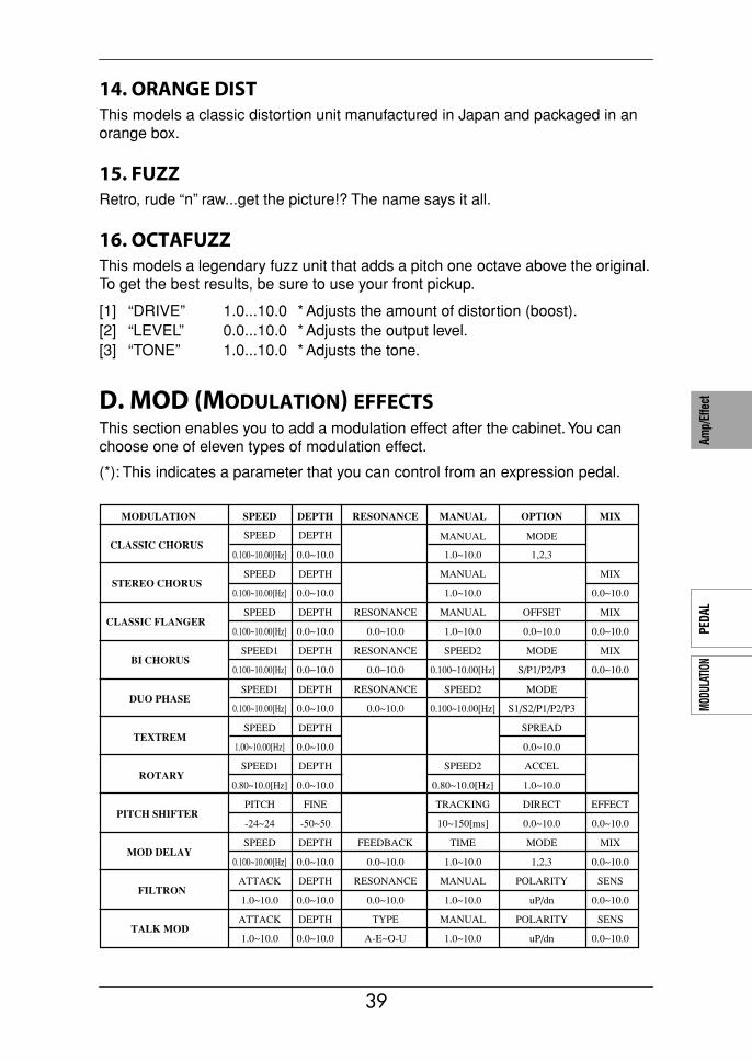
AMP
TYPE
CABI
NET
TYPE
PEDA
LMO
DULA
TION
DELA
YRE
VERB
Amp/
Effe
ct
14. ORANGE DISTThis models a classic distortion unit manufactured in Japan and packaged in an orange box.
15. FUZZRetro, rude “n” raw...get the picture!? The name says it all.
16. OCTAFUZZThis models a legendary fuzz unit that adds a pitch one octave above the original. To get the best results, be sure to use your front pickup.
D. MOD (MODULATION) EFFECTSThis section enables you to add a modulation effect after the cabinet. You can choose one of eleven types of modulation effect.
(*): This indicates a parameter that you can control from an expression pedal.
[1] “DRIVE” 1.0...10.0 * Adjusts the amount of distortion (boost).[2] “LEVEL” 0.0...10.0 * Adjusts the output level.[3] “TONE” 1.0...10.0 * Adjusts the tone.
CLASSIC CHORUS0.100~10.00[Hz] 0.0~10.0 1.0~10.0 1,2,3
SPEED
SPEED
DEPTH
DEPTH
MANUAL MIXSTEREO CHORUS
0.100~10.00[Hz] 0.0~10.0 1.0~10.0 0.0~10.0
SPEED DEPTH RESONANCE MANUAL
MANUAL
OFFSET MIXCLASSIC FLANGER
0.100~10.00[Hz] 0.0~10.0 0.0~10.0 1.0~10.0 0.0~10.0 0.0~10.0
SPEED1 DEPTH RESONANCE SPEED2 MODE
MODE
MIXBI CHORUS
0.100~10.00[Hz] 0.0~10.0 0.0~10.0 0.100~10.00[Hz] S/P1/P2/P3 0.0~10.0
SPEED1 DEPTH RESONANCE SPEED2 MODEDUO PHASE
0.100~10.00[Hz] 0.0~10.0 0.0~10.0 0.100~10.00[Hz] S1/S2/P1/P2/P3
SPEED DEPTH SPREADTEXTREM
1.00~10.00[Hz] 0.0~10.0 0.0~10.0
SPEED1 DEPTH SPEED2 ACCELROTARY
0.80~10.0[Hz] 0.0~10.0 0.80~10.0[Hz] 1.0~10.0
PITCH FINE TRACKING DIRECT EFFECTPITCH SHIFTER
-24~24 -50~50 10~150[ms] 0.0~10.0 0.0~10.0
SPEED DEPTH FEEDBACK TIME MODE MIXMOD DELAY
0.100~10.00[Hz] 0.0~10.0 0.0~10.0 1.0~10.0 1,2,3 0.0~10.0
ATTACK DEPTH RESONANCE MANUAL POLARITY SENSFILTRON
1.0~10.0 0.0~10.0 0.0~10.0 1.0~10.0 uP/dn 0.0~10.0
ATTACK DEPTH TYPE MANUAL POLARITY SENSTALK MOD
1.0~10.0 0.0~10.0 A-E~O-U 1.0~10.0 uP/dn 0.0~10.0
MODULATION SPEED DEPTH RESONANCE MANUAL OPTION MIX
39
1. CLASSIC CHORUS (CL CHORUS) MONO IN/MONO OUT 1 (MODE=1,3) MONO IN/MONO OUT 3 (MODE=2)This models a chorus unit that has two modes (chorus and vibrato), and is best-known for being built into a guitar amp. There’s no parameter to switch between chorus and vibrato, but you can use the SPEED and DEPTH knobs to create either of these sounds, giving you an even broader range of possibilities than the original unit! The output vibrato mode allows you to create vibrato (pitch modula-tion) by outputting just the effect sound.
2. STEREO CHORUS (ST CHORUS) MONO IN/STEREO OUT 1A stereo chorus in a yellow case. A sense of stereo is created by inverting the phase of the effect sound for the right output, producing a feeling of spaciousness that is somewhat different than the stereo effect of CLASSIC CHORUS.
3. CLASSIC FLANGER (CL FLANG) MONO IN/MONO OUT 1A model of a truly classic analogue flanger that “unchained” a highly influential modern guitarist who many hail as the “godfather of two handed tapping.”
[1] “SPEED” 0.100–10.00 [Hz] * Adjusts the modulation speed.[2] “DEPTH” 0.0–10.0 * Adjusts the modulation depth.[4] “MANUAL” 1.0–10.0 * Adjusts the center frequency of the sweep. If
DEPTH is set to 10, MANUAL will not function.[5] “MODE” 1, 2, 3 Selects the output mode.
1: Mono output.2: Stereo mode in which the effect is panned
right, and the dry sound panned left.3: Vibrato mode, in which only the effect sound is
output. Setting MANUAL to 10 will minimize the delay of the output sound.
[1] SPEED 0.100–10.00 [Hz] * Adjusts the modulation speed.[2] DEPTH 0.0–10.0 * Adjusts the modulation depth.[3] MANUAL 1.0–10.0 * Adjusts the center frequency of the sweep. If
DEPTH is set to 10, MANUAL will not function.[6] MIX 0.0–10.0 * Adjusts the mix amount of the effect sound.
[1] “SPEED” 0.100–10.00 [Hz] * Adjusts the modulation speed.[2] “DEPTH” 0.0–10.0 * Adjusts the modulation depth.[3] “RESO” 0.0–10.0 * Adjusts the amount of resonance.[4] “MANUAL” 1.0–10.0 * Adjusts the center frequency of the sweep. If
DEPTH is set to 10, MANUAL will not function.[5] “OFFSET” 0.0–10.0 Adjusts the starting position of the LFO. If you
assign “FLN TRIG” to a control pedal, the LFO will be reset to the starting position specified by OFF-SET whenever you operate the control pedal. When you defeat BYPASS, the LFO will start from the posi-tion you specify here. (p.56 Control pedal settings)
40
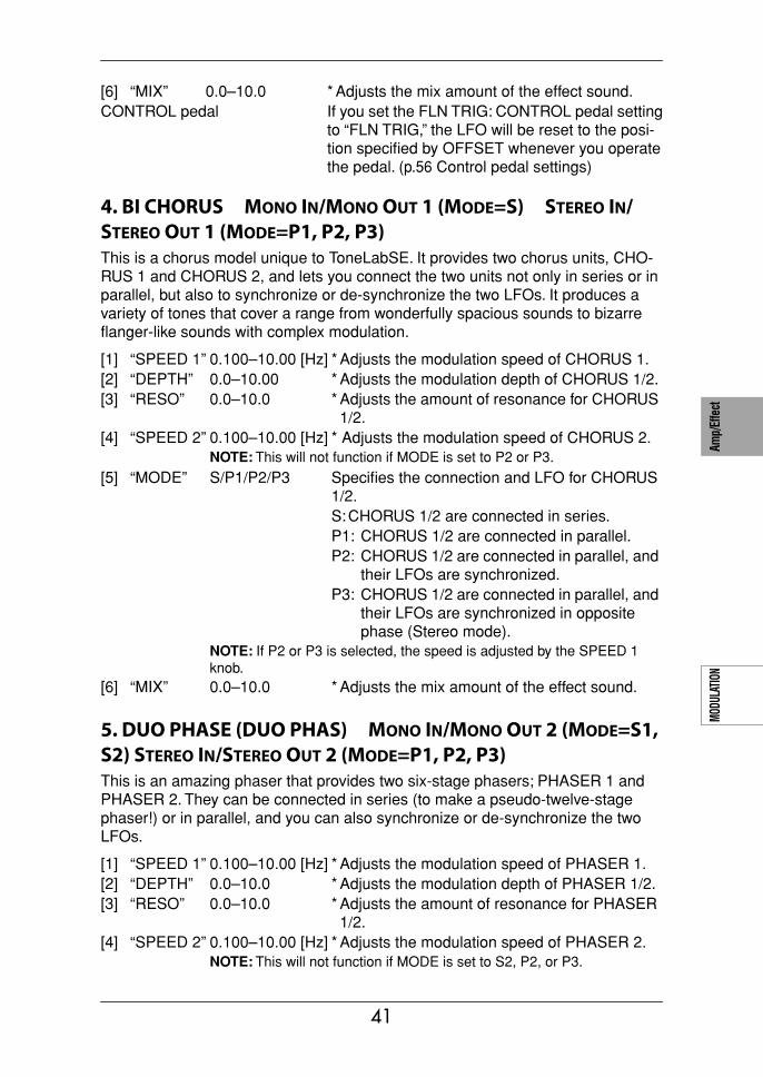
AMP
TYPE
CABI
NET
TYPE
PEDA
LMO
DULA
TION
DELA
YRE
VERB
Amp/
Effe
ct
4. BI CHORUS MONO IN/MONO OUT 1 (MODE=S) STEREO IN/STEREO OUT 1 (MODE=P1, P2, P3)This is a chorus model unique to ToneLabSE. It provides two chorus units, CHO-RUS 1 and CHORUS 2, and lets you connect the two units not only in series or in parallel, but also to synchronize or de-synchronize the two LFOs. It produces a variety of tones that cover a range from wonderfully spacious sounds to bizarre flanger-like sounds with complex modulation.
5. DUO PHASE (DUO PHAS) MONO IN/MONO OUT 2 (MODE=S1, S2) STEREO IN/STEREO OUT 2 (MODE=P1, P2, P3)This is an amazing phaser that provides two six-stage phasers; PHASER 1 and PHASER 2. They can be connected in series (to make a pseudo-twelve-stage phaser!) or in parallel, and you can also synchronize or de-synchronize the two LFOs.
[6] “MIX” 0.0–10.0 * Adjusts the mix amount of the effect sound.CONTROL pedal If you set the FLN TRIG: CONTROL pedal setting
to “FLN TRIG,” the LFO will be reset to the posi-tion specified by OFFSET whenever you operate the pedal. (p.56 Control pedal settings)
[1] “SPEED 1” 0.100–10.00 [Hz] * Adjusts the modulation speed of CHORUS 1.[2] “DEPTH” 0.0–10.00 * Adjusts the modulation depth of CHORUS 1/2.[3] “RESO” 0.0–10.0 * Adjusts the amount of resonance for CHORUS
1/2.[4] “SPEED 2” 0.100–10.00 [Hz] * Adjusts the modulation speed of CHORUS 2.
NOTE: This will not function if MODE is set to P2 or P3.
[5] “MODE” S/P1/P2/P3 Specifies the connection and LFO for CHORUS 1/2.S:CHORUS 1/2 are connected in series.P1: CHORUS 1/2 are connected in parallel.P2: CHORUS 1/2 are connected in parallel, and
their LFOs are synchronized.P3: CHORUS 1/2 are connected in parallel, and
their LFOs are synchronized in opposite phase (Stereo mode).
NOTE: If P2 or P3 is selected, the speed is adjusted by the SPEED 1 knob.
[6] “MIX” 0.0–10.0 * Adjusts the mix amount of the effect sound.
[1] “SPEED 1” 0.100–10.00 [Hz] * Adjusts the modulation speed of PHASER 1.[2] “DEPTH” 0.0–10.0 * Adjusts the modulation depth of PHASER 1/2.[3] “RESO” 0.0–10.0 * Adjusts the amount of resonance for PHASER
1/2.[4] “SPEED 2” 0.100–10.00 [Hz] * Adjusts the modulation speed of PHASER 2.
NOTE: This will not function if MODE is set to S2, P2, or P3.
41
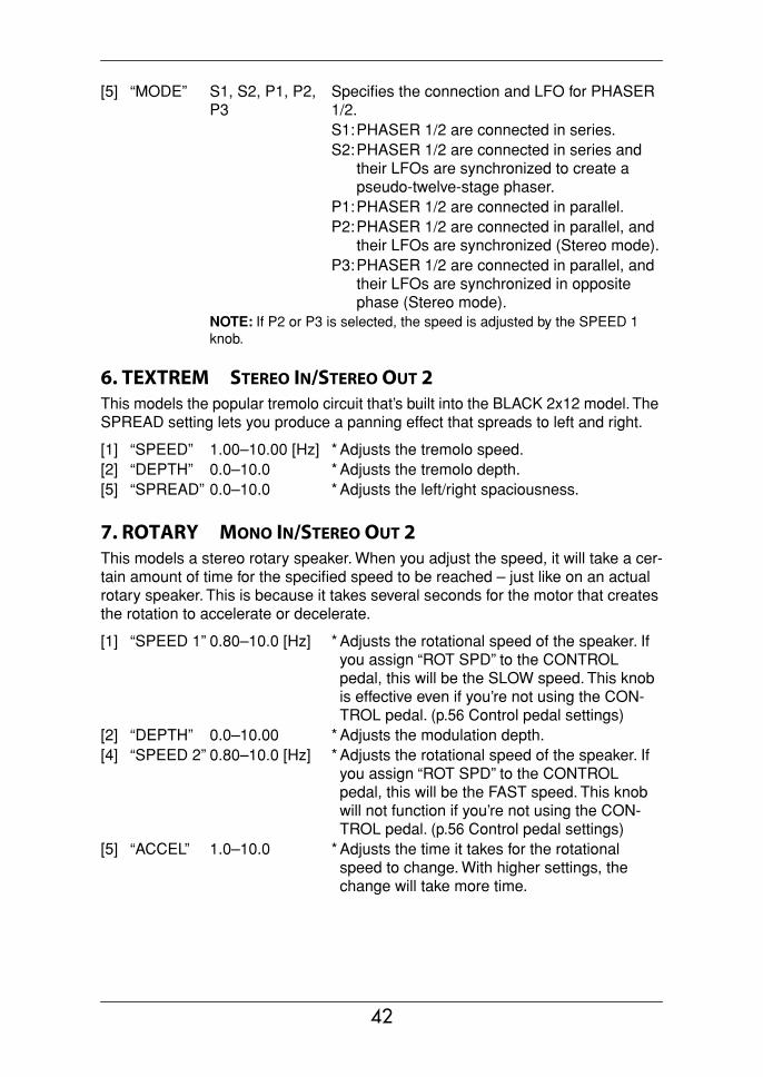
6. TEXTREM STEREO IN/STEREO OUT 2This models the popular tremolo circuit that’s built into the BLACK 2x12 model. The SPREAD setting lets you produce a panning effect that spreads to left and right.
7. ROTARY MONO IN/STEREO OUT 2This models a stereo rotary speaker. When you adjust the speed, it will take a cer-tain amount of time for the specified speed to be reached – just like on an actual rotary speaker. This is because it takes several seconds for the motor that creates the rotation to accelerate or decelerate.
[5] “MODE” S1, S2, P1, P2, P3
Specifies the connection and LFO for PHASER 1/2.S1:PHASER 1/2 are connected in series.S2:PHASER 1/2 are connected in series and
their LFOs are synchronized to create a pseudo-twelve-stage phaser.
P1:PHASER 1/2 are connected in parallel.P2:PHASER 1/2 are connected in parallel, and
their LFOs are synchronized (Stereo mode).P3:PHASER 1/2 are connected in parallel, and
their LFOs are synchronized in opposite phase (Stereo mode).
NOTE: If P2 or P3 is selected, the speed is adjusted by the SPEED 1 knob.
[1] “SPEED” 1.00–10.00 [Hz] * Adjusts the tremolo speed.[2] “DEPTH” 0.0–10.0 * Adjusts the tremolo depth.[5] “SPREAD” 0.0–10.0 * Adjusts the left/right spaciousness.
[1] “SPEED 1” 0.80–10.0 [Hz] * Adjusts the rotational speed of the speaker. If you assign “ROT SPD” to the CONTROL pedal, this will be the SLOW speed. This knob is effective even if you’re not using the CON-TROL pedal. (p.56 Control pedal settings)
[2] “DEPTH” 0.0–10.00 * Adjusts the modulation depth.[4] “SPEED 2” 0.80–10.0 [Hz] * Adjusts the rotational speed of the speaker. If
you assign “ROT SPD” to the CONTROL pedal, this will be the FAST speed. This knob will not function if you’re not using the CON-TROL pedal. (p.56 Control pedal settings)
[5] “ACCEL” 1.0–10.0 * Adjusts the time it takes for the rotational speed to change. With higher settings, the change will take more time.
42

AMP
TYPE
CABI
NET
TYPE
PEDA
LMO
DULA
TION
DELA
YRE
VERB
Amp/
Effe
ct
8. PITCH SHIFTER (PITCH) MONO IN/MONO OUT 1This is a pitch shifter with a range of two octaves up or down, rivaling sophisticated rack-mounted signal processors.
PITCH SHIFTER TIPS: If you assign the PITCH knob to an expression pedal, you can use the pedal to control the pitch change. (p.53 Using the expression pedal to control the sound)
9. MOD DELAY (MOD DLY) MONO IN/MONO OUT 1 (MODE=1) MONO IN/MONO OUT 3 (MODE=2) MONO IN/STEREO OUT 1 (MODE=3)This models an analog delay that lets you add a vibrato effect to the delayed sound. The actual unit provided 400 ms of delay time, but this simulation extends this up to 1400 ms while maintaining the same warm sound, and can also be used as a sub-delay for the DELAY section. The CHORUS/VIBRATO switch of the origi-nal unit has been replaced by a knob with a range of 0.1–10 Hz, giving you even more versatility than the original.
CONTROL pedal: ROT SPD: If you select “ROT SPD” as the CONTROL pedal setting, the rotation speed will alternate between SLOW/FAST (SPEED 1/SPEED 2) each time you press the CONTROL pedal switch. This lets you control the effect just as on an actual rotary speaker. (p.56 Control pedal settings)
[1] “PITCH” –24–+24 * Adjusts the pitch in 100-cent units.[2] “FINE” –50–+50 * Adjusts the pitch in one-cent units.[4] “TRACKING” 10–150 [ms] Adjusts the tracking of the pitch shifter (i.e., how
closely it will follow). Shorter settings are effective if the PITCH setting is close to 0, and longer settings are effective if the PITCH setting is close to +/–24. While listening to the pitch-shifted sound, adjust this so that you do not have difficulty playing.
[5] “DIRECT” 0.0–10.0 * Adjusts the level of the direct sound.[6] “EFFECT” 0.0–10.0 * Adjusts the level of the effect sound.
[1] “SPEED” 0.100–10.00 [Hz] * Adjusts the modulation speed.[2] “DEPTH” 0.0–10.0 * Adjusts the modulation depth.[3] “FEEDBACK” 0.0–10.0 * Adjusts the amount of feedback.[4] “TIME” 1.0–10.0 * Specifies the delay time.[5] “MODE” 1,2,3 Selects the output method.
1: Mono output.2: Stereo mode with effect sound from the
right and dry sound from the left.3: Reverse-phase stereo mode with dry +
effect in the left side and dry - effect in the right side.
[6] “MIX” 0.0–10.0 * Adjusts the mix amount of the effect sound.
43
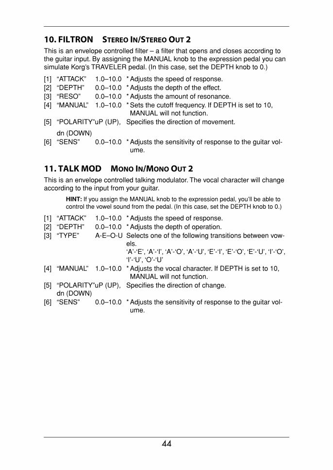
10. FILTRON STEREO IN/STEREO OUT 2This is an envelope controlled filter – a filter that opens and closes according to the guitar input. By assigning the MANUAL knob to the expression pedal you can simulate Korg’s TRAVELER pedal. (In this case, set the DEPTH knob to 0.)
11. TALK MOD MONO IN/MONO OUT 2This is an envelope controlled talking modulator. The vocal character will change according to the input from your guitar.
HINT: If you assign the MANUAL knob to the expression pedal, you’ll be able to control the vowel sound from the pedal. (In this case, set the DEPTH knob to 0.)
[1] “ATTACK” 1.0–10.0 * Adjusts the speed of response.[2] “DEPTH” 0.0–10.0 * Adjusts the depth of the effect.[3] “RESO” 0.0–10.0 * Adjusts the amount of resonance.[4] “MANUAL” 1.0–10.0 * Sets the cutoff frequency. If DEPTH is set to 10,
MANUAL will not function.[5] “POLARITY”uP (UP),
dn (DOWN)
Specifies the direction of movement.
[6] “SENS” 0.0–10.0 * Adjusts the sensitivity of response to the guitar vol-ume.
[1] “ATTACK” 1.0–10.0 * Adjusts the speed of response.[2] “DEPTH” 0.0–10.0 * Adjusts the depth of operation.[3] “TYPE” A-E–O-U Selects one of the following transitions between vow-
els.‘A’-‘E’, ‘A’-‘I’, ‘A’-‘O’, ‘A’-‘U’, ‘E’-‘I’, ‘E’-‘O’, ‘E’-‘U’, ‘I’-‘O’, ‘I’-‘U’, ‘O’-‘U’
[4] “MANUAL” 1.0–10.0 * Adjusts the vocal character. If DEPTH is set to 10, MANUAL will not function.
[5] “POLARITY”uP (UP), dn (DOWN)
Specifies the direction of change.
[6] “SENS” 0.0–10.0 * Adjusts the sensitivity of response to the guitar vol-ume.
44
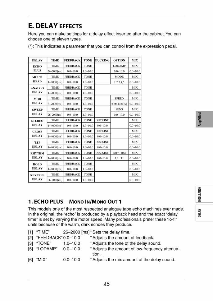
AMP
TYPE
CABI
NET
TYPE
PEDA
LMO
DULA
TION
DELA
YRE
VERB
Amp/
Effe
ct
E. DELAY EFFECTSHere you can make settings for a delay effect inserted after the cabinet. You can choose one of eleven types.
(*): This indicates a parameter that you can control from the expression pedal.
1. ECHO PLUS MONO IN/MONO OUT 1This models one of the most respected analogue tape echo machines ever made. In the original, the “echo” is produced by a playback head and the exact “delay time” is set by varying the motor speed. Many professionals prefer these “lo-fi” units because of the warm, dark echoes they produce.
[1] “TIME” 26–2000 [ms] * Sets the delay time.[2] “FEEDBACK” 0.0–10.0 * Adjusts the amount of feedback.[3] “TONE” 1.0–10.0 * Adjusts the tone of the delay sound.[5] “LODAMP” 0.0–10.0 * Adjusts the amount of low-frequency attenua-
tion.[6] “MIX” 0.0–10.0 * Adjusts the mix amount of the delay sound.
DELAY TIME FEEDBACK TONE DUCKING OPTION MIX
TIME FEEDBACK TONE LODAMP MIXECHOPLUS 26~2000[ms] 0.0~10.0 1.0~10.0 0.0~10.0 0.0~10.0
TIME FEEDBACK TONE MODE MIXMULTIHEAD 1~2000[ms] 0.0~10.0 1.0~10.0 1,2,3,4,5 0.0~10.0
TIME FEEDBACK TONE MIXANALOGDELAY 1~2000[ms] 0.0~10.0 1.0~10.0 0.0~10.0
TIME FEEDBACK TONE SPEED MIXMOD
SWEEP
DELAY 3~2000[ms] 0.0~10.0 1.0~10.0 0.100~10.00[Hz] 0.0~10.0
TIME FEEDBACK TONE SENS MIX
DELAY 26~2000[ms] 0.0~10.0 1.0~10.0 0.0~10.0 0.0~10.0
TIME FEEDBACK TONE DUCKING MIXSTEREODELAY 1~4000[ms] 0.0~10.0 1.0~10.0 0.0~10.0 0.0~10.0
TIME FEEDBACK TONE DUCKING MIXCROSSDELAY 1~4000[ms] 0.0~10.0 1.0~10.0 0.0~10.0 0.0~10.0
TIME FEEDBACK TONE DUCKING MIX2TAPDELAY 1~4000[ms] 0.0~10.0 1.0~10.0 0.0~10.0 0.0~10.0
TIME FEEDBACK TONE DUCKING RHYTHM MIXRHYTHMDELAY 1~4000[ms] 0.0~10.0 1.0~10.0 0.0~10.0 1,2,..11 0.0~10.0
TIME FEEDBACK TONE MIXHOLDDELAY 1~8000[ms] 0.0~10.0 1.0~10.0 0.0~10.0
TIME FEEDBACK TONE MIXREVERSEDELAY 26~4000[ms] 0.0~10.0 1.0~10.0 0.0~10.0
45
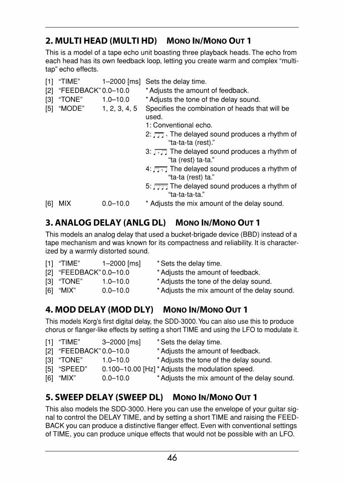
2. MULTI HEAD (MULTI HD) MONO IN/MONO OUT 1This is a model of a tape echo unit boasting three playback heads. The echo from each head has its own feedback loop, letting you create warm and complex “multi-tap” echo effects.
3. ANALOG DELAY (ANLG DL) MONO IN/MONO OUT 1This models an analog delay that used a bucket-brigade device (BBD) instead of a tape mechanism and was known for its compactness and reliability. It is character-ized by a warmly distorted sound.
4. MOD DELAY (MOD DLY) MONO IN/MONO OUT 1This models Korg’s first digital delay, the SDD-3000. You can also use this to produce chorus or flanger-like effects by setting a short TIME and using the LFO to modulate it.
5. SWEEP DELAY (SWEEP DL) MONO IN/MONO OUT 1This also models the SDD-3000. Here you can use the envelope of your guitar sig-nal to control the DELAY TIME, and by setting a short TIME and raising the FEED-BACK you can produce a distinctive flanger effect. Even with conventional settings of TIME, you can produce unique effects that would not be possible with an LFO.
[1] “TIME” 1–2000 [ms] Sets the delay time.[2] “FEEDBACK” 0.0–10.0 * Adjusts the amount of feedback.[3] “TONE” 1.0–10.0 * Adjusts the tone of the delay sound.[5] “MODE” 1, 2, 3, 4, 5 Specifies the combination of heads that will be
used.1: Conventional echo.2: The delayed sound produces a rhythm of
“ta-ta-ta (rest).”3: The delayed sound produces a rhythm of
“ta (rest) ta-ta.”4: The delayed sound produces a rhythm of
“ta-ta (rest) ta.”5: The delayed sound produces a rhythm of
“ta-ta-ta-ta.”[6] MIX 0.0–10.0 * Adjusts the mix amount of the delay sound.
[1] “TIME” 1–2000 [ms] * Sets the delay time.[2] “FEEDBACK” 0.0–10.0 * Adjusts the amount of feedback.[3] “TONE” 1.0–10.0 * Adjusts the tone of the delay sound.[6] “MIX” 0.0–10.0 * Adjusts the mix amount of the delay sound.
[1] “TIME” 3–2000 [ms] * Sets the delay time.[2] “FEEDBACK” 0.0–10.0 * Adjusts the amount of feedback.[3] “TONE” 1.0–10.0 * Adjusts the tone of the delay sound.[5] “SPEED” 0.100–10.00 [Hz] * Adjusts the modulation speed.[6] “MIX” 0.0–10.0 * Adjusts the mix amount of the delay sound.
46
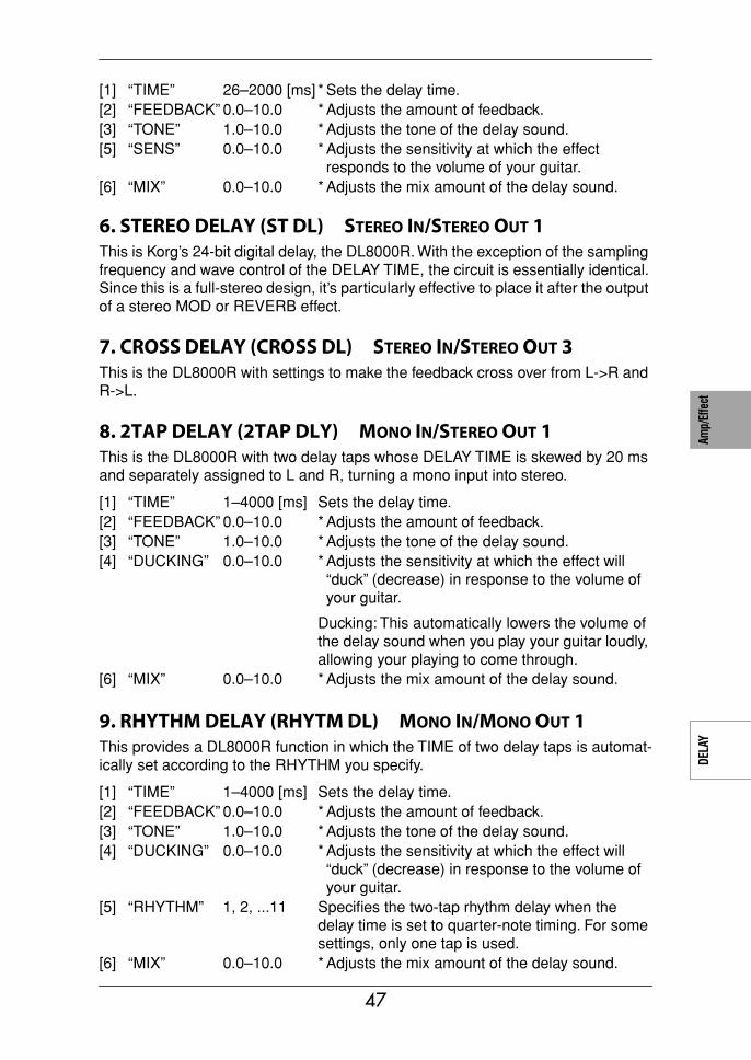
AMP
TYPE
CABI
NET
TYPE
PEDA
LMO
DULA
TION
DELA
YRE
VERB
Amp/
Effe
ct
6. STEREO DELAY (ST DL) STEREO IN/STEREO OUT 1This is Korg’s 24-bit digital delay, the DL8000R. With the exception of the sampling frequency and wave control of the DELAY TIME, the circuit is essentially identical. Since this is a full-stereo design, it’s particularly effective to place it after the output of a stereo MOD or REVERB effect.
7. CROSS DELAY (CROSS DL) STEREO IN/STEREO OUT 3This is the DL8000R with settings to make the feedback cross over from L->R and R->L.
8. 2TAP DELAY (2TAP DLY) MONO IN/STEREO OUT 1This is the DL8000R with two delay taps whose DELAY TIME is skewed by 20 ms and separately assigned to L and R, turning a mono input into stereo.
9. RHYTHM DELAY (RHYTM DL) MONO IN/MONO OUT 1This provides a DL8000R function in which the TIME of two delay taps is automat-ically set according to the RHYTHM you specify.
[1] “TIME” 26–2000 [ms] * Sets the delay time.[2] “FEEDBACK” 0.0–10.0 * Adjusts the amount of feedback.[3] “TONE” 1.0–10.0 * Adjusts the tone of the delay sound.[5] “SENS” 0.0–10.0 * Adjusts the sensitivity at which the effect
responds to the volume of your guitar.[6] “MIX” 0.0–10.0 * Adjusts the mix amount of the delay sound.
[1] “TIME” 1–4000 [ms] Sets the delay time.[2] “FEEDBACK” 0.0–10.0 * Adjusts the amount of feedback.[3] “TONE” 1.0–10.0 * Adjusts the tone of the delay sound.[4] “DUCKING” 0.0–10.0 * Adjusts the sensitivity at which the effect will
“duck” (decrease) in response to the volume of your guitar.
Ducking: This automatically lowers the volume of the delay sound when you play your guitar loudly, allowing your playing to come through.
[6] “MIX” 0.0–10.0 * Adjusts the mix amount of the delay sound.
[1] “TIME” 1–4000 [ms] Sets the delay time.[2] “FEEDBACK” 0.0–10.0 * Adjusts the amount of feedback.[3] “TONE” 1.0–10.0 * Adjusts the tone of the delay sound.[4] “DUCKING” 0.0–10.0 * Adjusts the sensitivity at which the effect will
“duck” (decrease) in response to the volume of your guitar.
[5] “RHYTHM” 1, 2, ...11 Specifies the two-tap rhythm delay when the delay time is set to quarter-note timing. For some settings, only one tap is used.
[6] “MIX” 0.0–10.0 * Adjusts the mix amount of the delay sound.
47
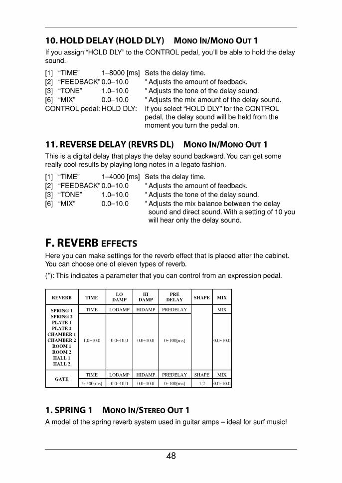
10. HOLD DELAY (HOLD DLY) MONO IN/MONO OUT 1If you assign “HOLD DLY” to the CONTROL pedal, you’ll be able to hold the delay sound.
11. REVERSE DELAY (REVRS DL) MONO IN/MONO OUT 1This is a digital delay that plays the delay sound backward. You can get some really cool results by playing long notes in a legato fashion.
F. REVERB EFFECTSHere you can make settings for the reverb effect that is placed after the cabinet. You can choose one of eleven types of reverb.
(*): This indicates a parameter that you can control from an expression pedal.
1. SPRING 1 MONO IN/STEREO OUT 1A model of the spring reverb system used in guitar amps – ideal for surf music!
[1] “TIME” 1–8000 [ms] Sets the delay time.[2] “FEEDBACK” 0.0–10.0 * Adjusts the amount of feedback.[3] “TONE” 1.0–10.0 * Adjusts the tone of the delay sound.[6] “MIX” 0.0–10.0 * Adjusts the mix amount of the delay sound.CONTROL pedal: HOLD DLY: If you select “HOLD DLY” for the CONTROL
pedal, the delay sound will be held from the moment you turn the pedal on.
[1] “TIME” 1–4000 [ms] Sets the delay time.[2] “FEEDBACK” 0.0–10.0 * Adjusts the amount of feedback.[3] “TONE” 1.0–10.0 * Adjusts the tone of the delay sound.[6] “MIX” 0.0–10.0 * Adjusts the mix balance between the delay
sound and direct sound. With a setting of 10 you will hear only the delay sound.
REVERB TIMELO
DAMPHI
DAMPPRE
DELAY SHAPE MIX
TIME LODAMP HIDAMP PREDELAY MIXSPRING 1SPRING 2PLATE 1PLATE 2
CHAMBER 1CHAMBER 2
ROOM 1ROOM 2HALL 1HALL 2
1.0~10.0 0.0~10.0 0.0~10.0 0~100[ms] 0.0~10.0
TIME LODAMP HIDAMP PREDELAY SHAPE MIXGATE
5~500[ms] 0.0~10.0 0.0~10.0 0~100[ms] 1,2 0.0~10.0
48
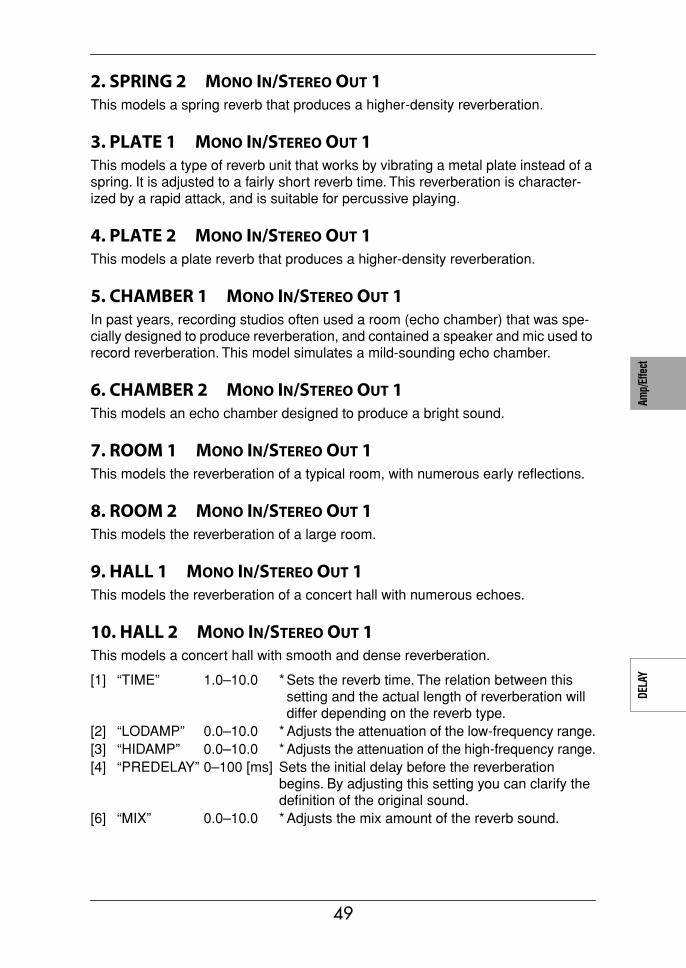
AMP
TYPE
CABI
NET
TYPE
PEDA
LMO
DULA
TION
DELA
YRE
VERB
Amp/
Effe
ct
2. SPRING 2 MONO IN/STEREO OUT 1This models a spring reverb that produces a higher-density reverberation.
3. PLATE 1 MONO IN/STEREO OUT 1This models a type of reverb unit that works by vibrating a metal plate instead of a spring. It is adjusted to a fairly short reverb time. This reverberation is character-ized by a rapid attack, and is suitable for percussive playing.
4. PLATE 2 MONO IN/STEREO OUT 1This models a plate reverb that produces a higher-density reverberation.
5. CHAMBER 1 MONO IN/STEREO OUT 1In past years, recording studios often used a room (echo chamber) that was spe-cially designed to produce reverberation, and contained a speaker and mic used to record reverberation. This model simulates a mild-sounding echo chamber.
6. CHAMBER 2 MONO IN/STEREO OUT 1This models an echo chamber designed to produce a bright sound.
7. ROOM 1 MONO IN/STEREO OUT 1This models the reverberation of a typical room, with numerous early reflections.
8. ROOM 2 MONO IN/STEREO OUT 1This models the reverberation of a large room.
9. HALL 1 MONO IN/STEREO OUT 1This models the reverberation of a concert hall with numerous echoes.
10. HALL 2 MONO IN/STEREO OUT 1This models a concert hall with smooth and dense reverberation.
[1] “TIME” 1.0–10.0 * Sets the reverb time. The relation between this setting and the actual length of reverberation will differ depending on the reverb type.
[2] “LODAMP” 0.0–10.0 * Adjusts the attenuation of the low-frequency range.[3] “HIDAMP” 0.0–10.0 * Adjusts the attenuation of the high-frequency range.[4] “PREDELAY” 0–100 [ms] Sets the initial delay before the reverberation
begins. By adjusting this setting you can clarify the definition of the original sound.
[6] “MIX” 0.0–10.0 * Adjusts the mix amount of the reverb sound.
49
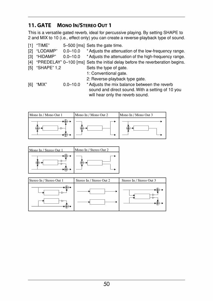
11. GATE MONO IN/STEREO OUT 1This is a versatile gated reverb, ideal for percussive playing. By setting SHAPE to 2 and MIX to 10 (i.e., effect only) you can create a reverse-playback type of sound.
[1] “TIME” 5–500 [ms] Sets the gate time.[2] “LODAMP” 0.0–10.0 * Adjusts the attenuation of the low-frequency range.[3] “HIDAMP” 0.0–10.0 * Adjusts the attenuation of the high-frequency range.[4] “PREDELAY” 0–100 [ms] Sets the initial delay before the reverberation begins.[5] “SHAPE” 1,2 Sets the type of gate.
1: Conventional gate.2: Reverse-playback type gate.
[6] “MIX” 0.0–10.0 * Adjusts the mix balance between the reverb sound and direct sound. With a setting of 10 you will hear only the reverb sound.
Mono In / Mono Out 1
Mono In / Stereo Out 1
Mono In / Mono Out 2 Mono In / Mono Out 3
Mono In / Stereo Out 2
Stereo In / Stereo Out 1 Stereo In / Stereo Out 2 Stereo In / Stereo Out 3
50
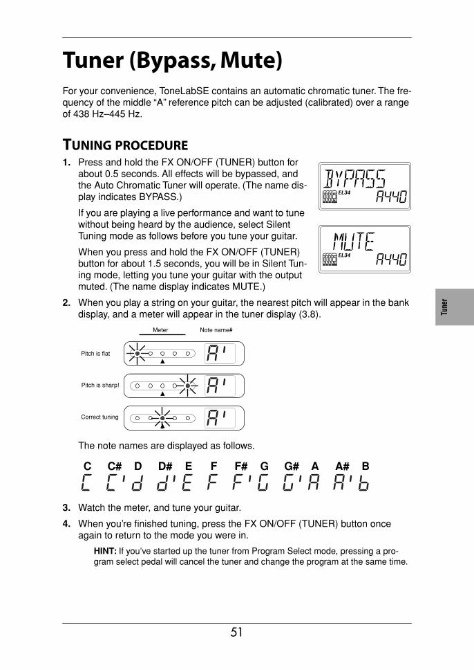
Tune
rPe
dals
MIDI
/DIG
ITAL
Facto
ryse
tting
sTr
oubl
e-sh
ootin
gSp
ec.
Prog
ram
List
Tuner (Bypass, Mute)For your convenience, ToneLabSE contains an automatic chromatic tuner. The fre-quency of the middle “A” reference pitch can be adjusted (calibrated) over a range of 438 Hz–445 Hz.
TUNING PROCEDURE1. Press and hold the FX ON/OFF (TUNER) button for
about 0.5 seconds. All effects will be bypassed, and the Auto Chromatic Tuner will operate. (The name dis-play indicates BYPASS.)
If you are playing a live performance and want to tune without being heard by the audience, select Silent Tuning mode as follows before you tune your guitar.
When you press and hold the FX ON/OFF (TUNER) button for about 1.5 seconds, you will be in Silent Tun-ing mode, letting you tune your guitar with the output muted. (The name display indicates MUTE.)
2. When you play a string on your guitar, the nearest pitch will appear in the bank display, and a meter will appear in the tuner display (3.8).
The note names are displayed as follows.
3. Watch the meter, and tune your guitar.
4. When you’re finished tuning, press the FX ON/OFF (TUNER) button once again to return to the mode you were in.
HINT: If you’ve started up the tuner from Program Select mode, pressing a pro-gram select pedal will cancel the tuner and change the program at the same time.
Pitch is flat
Pitch is sharp!
Correct tuning
Note name#Meter
C C# D D# E F F# G G# A A# B
51

CALIBRATING THE TUNERWhen you switch ToneLabSE on, the built-in tuner is automatically calibrated to A=440 Hz (a.k.a. “concert pitch”). If desired, you can recalibrate the tuner in the range of A = 438 Hz–445 Hz.
• While the tuner is active, the value display (3.10) shows the frequency of the ref-erence pitch. You can use the ▲, ▼ buttons to adjust (calibrate) this in the range of 438 Hz–445 Hz.
NOTE: If you’ve recalibrated the tuner, remember that the setting will be automati-cally reset to 440 Hz the next time you turn ToneLabSE on.
52

Tune
rPe
dals
MIDI
/DIG
ITAL
Facto
ryse
tting
sTr
oubl
e-sh
ootin
gSp
ec.
Prog
ram
List
Using the expression pedals
EXPRESSION PEDAL SETTINGSToneLabSE provides two expression pedals that you can use to control not only wah or volume, but a wide variety of effect parameters. For each program, you can specify which effect will be controlled, and how.
HINT: If you’ve assigned a parameter to an expression pedal, operating the pedal has the same result as using the knob to edit the program. This means that when you operate the pedal, the EDIT icon will light. When you write the program, it will be written with the sound as currently specified by the position of the pedal. How-ever if the expression target is “--OFF--,” “VOLUME,” “M/PITCH,” “D/INPUT,” or “R/INPUT,” the program will not be edited by the pedal.
EXPRESSION TARGET QUICK ASSIGN
Here’s a very easy and convenient way to set the expression target.
As an example, use the MODULATION selector to choose PITCH SHIFTER. So that the effect will be easy to hear, we’ll initialize the PITCH SHIFTER. If PITCH SHIFTER is already selected, turn the selector to choose a different effect, and then re-select PITCH SHIFTER.
1. When you’re editing PITCH SHIFTER, turn value knob 1 or use the √√√√, ®®®® but-tons to make the name display show PITCH; the EXPRESSION button will light. If in this state you press and hold (for one second) the EXPRESSION button, the name display will indicate COMPLETE. The PITCH parameter has now been assigned to expression pedal 1, letting you control the amount of PITCH SHIFT. If you want to make more detailed settings, you can press the EXPRESSION button and set the minimum value (“EXP1 MIN,” value knob 2) and maximum value (“EXP1 MAX,” value knob 3) of the target range.
In the same way, whenever the EXPRESSION button is lit during editing, you can press and hold the CONTROL button for one second to assign expression pedal 2 to control the parameter that is currently shown in the name display.
NOTE: If you change the effect type of a parameter that is assigned to an expres-sion target (i.e., to be controlled by one of the expression pedals), the target will be initialized to a setting of “--OFF--”. (However, “A/*****”, “D/INPUT”, and “R/INPUT” are exceptions.)
HINT: If you’ve set the PEDAL effect type to “VOX WAH,” the “P/MANUAL” (wah position) will automatically be assigned to expression 1. If you then set the PEDAL effect to a different type without making any further settings, the Target, Min, and Max settings will automatically return to their former settings. (However in the case of “P/******”, it will be initialized to “--OFF--” instead of returning to its former set-ting.)
NOTE: When you change the expression target, the MIN and MAX values will be initialized.
53
SETTING THE EXPRESSION TARGET
Here are the items you can set.
When you’ve pressed the EXPRESSION button to make it blink, you’ll be able to set the following items by turning value knobs 1–6.
NOTE: You can set the above items individually for each program. If you switch to a different program or turn off the power without saving, any changes you’ve made will be lost.
Using the same example we described earlier when explaining Quick Assign, here’s how to assign expression pedal 1 to control the PITCH parameter of the PITCH SHIFTER modulation effect.
1. Use the MODULATION selector to select PITCH SHIFTER. So that the effect will be easy to hear, we’ll initialize the PITCH SHIFTER. If PITCH SHIFTER is already selected, turn the selector to choose a different effect, and then re-select PITCH SHIFTER.
NOTE: If you change the effect type of a parameter that is assigned to an expres-sion target, the target will be initialized to a setting of “--OFF--”. (However, “A/*****”, “D/INPUT”, and “R/INPUT” are exceptions.)
HINT: If you’ve set the PEDAL effect type to “VOX WAH,” the “P/MANUAL” (wah position) will automatically be assigned to expression 1. If you then set the PEDAL effect to a different type without making any further settings, the target setting will also automatically return to the former setting.
2. Press the EXPRESSION button to make it blink.
3. Press the ®®®® button or turn value knob 1 to make the value display read “E1”.
4. Use the ▲, ▼ buttons or turn value knob 1 to make the name display read “M/PITCH”. The PITCH parameter of the PITCH SHIFTER effect has now been assigned to expression pedal 1.
NOTE: Unlike other parameters, PITCH is not edited when you control it from an expression pedal. This is so that the pitch will change smoothly even when MIN and MAX are set to values that are close to each other (i.e., when you’ve made set-tings so that the pedal produces only a small amount of pitch change).
“*/######”: EXP 1 expression target (value display indicates E1) Value knob 1“EXP 1 MIN:” EXP 1 (expression pedal 1) target range (minimum value) Value knob 2“EXP 1 MAX:” EXP 1 (expression pedal 1) target range (maximum value) Value knob 3“*/######”: EXP 2 expression target (value display indicates E2) Value knob 4“EXP 2 MIN:” EXP 2 (expression pedal 2) target range (minimum value) Value knob 5“EXP 2 MAX:” EXP 2 (expression pedal 2) target range (maximum value) Value knob 6
54
Tune
rPe
dals
MIDI
/DIG
ITAL
Facto
ryse
tting
sTr
oubl
e-sh
ootin
gSp
ec.
Prog
ram
List
NOTE: Nothing will be controlled if the target effect is “OFF.”The expression pedal target is indicated as follows.“*/###### *: Target category, ######: Target parameter
• Examples
In addition to the examples we’ve shown here, a wide variety of expression tar-gets provided for each effect model can be freely assigned to the two expres-sion pedals.
If desired, you can make more detailed settings.
NOTE: For “--OFF--”, “VOLUME”, “M/PITCH”, “D/INPUT”, and “R/INPUT”, operat-ing the expression pedal does not edit the parameter.
5. Turn value knob 2 to make the name display read “EXP 1 MIN.” Here you can specify the PITCH value for when the pedal is at the minimum position. Use value knob 2 or the ▲, ▼ buttons to adjust the setting.
6. Turn value knob 3 to make the name display read “EXP 1 MAX.” Here you can specify the PITCH value for when the pedal is at the maximum position. Use value knob 3 or the ▲, ▼ buttons to adjust the setting.
When you operate the expression pedal, the target parameter will change within the range you specified here.
In the same way, you can use value knobs 4–6 or the ▲, ▼, √√√√, ®®®® buttons to make expression target parameter settings for expression pedal 2. (When you are making EXP2 expression target settings, the value display indicates “E2.”)
NOTE: When you change the expression target, the MIN and MAX values will be initialized.
7. Press the EXIT switch to return to the mode you were in.
NOTE: The changes you make will not be preserved in internal memory unless you store the program.
EXPRESSION PEDAL CONTROL INITIALIZATION SETTINGS
“EXP1INIT” Expression pedal 1 initialization setting“EXP2INIT” Expression pedal 2 initialization settingIf you press the ®®®® button several times while the EXPRESSION button is blinking, the “EXP1INIT” setting screen will appear.
If you then press the ®®®® button again, the “EXP2INIT” setting screen will appear.
“--OFF--” --- OFF (control nothing)“VOLUME” --- Volume pedal“P/DIRECT” --- (*: P (pedal)) DIRECT (mix amount of original sound)
for a pedal effect (e.g., OCTAVE)“M/SPEED” --- (*: M (modulation)) SPEED of a modulation effect“D/INPUT” --- (*: D (delay)) Input level of a delay effect“R/MIX” --- (*: R (reverb)) MIX (mix amount of reverb sound) of a
reverb effect“A/VRGN A” --- (*: A (amp)) [VR GAIN] (channel A) of an amp model
55
“EXP1INIT” lets you specify whether the control data for expression pedal 1 (i.e., the position of the pedal) will be maintained when you switch programs. (“EXP2INIT” does the same for expression pedal 2.)
Use the ▲, ▼ buttons to change the setting.
If this is turned “OFF”; the instant you switch programs, the parameter that is specified as the expression target will change to the current position of the pedal.
If this is turned “ON”; the parameter will be initialized to the same setting as when the program was saved (i.e., the control data will be initialized).
Press the EXIT switch to exit this editing operation and return to the mode in which you were.
NOTE: The “EXP1INIT” and “EXP2INIT” settings are not saved in a program; these settings apply to all programs in common, and the setting is saved automatically.
CONTROL SWITCH SETTINGSYou can make the following control pedal settings independently for each program.
Press the CONTROL button to make it blink, and use value knob 1 to select the effect you want to control.
SWITCHING EACH EFFECT ON/OFF
NOTE: The CONTROL button LEDs indicate the on/off status.
USING TAP TEMPO TO SET A PARAMETER
NOTE: The CONTROL button LED will blink at the tempo you specify.
FACTOR VALUE KNOB 2 SETTING
If the MODULATION effect’s SPEED parameter or the DELAY effect’s TIME parame-ter are assigned to a control pedal, you can set the MODULATION effect’s LFO SPEED or the DELAY effect’s DELAY TIME by the interval at which you press the con-trol pedal twice. When you do so, the interval at which you actually press the pedal will
• “I/ON OFF” External effect insertion on/off• “P/ON OFF” Pedal effect on/off• “A/ON OFF” Amp model on/off• “C/ON OFF” Cabinet effect on/off• “M/ON OFF” Modulation effect on/off• “D/ON OFF” Delay effect on/off• “R/ON OFF” Reverb effect on/off
• “MOD TAP” Use TAP TEMPO to set the SPEED parameter of the modulation effect
• “DLY TAP” Use TAP TEMPO to set the TIME parameter of the delay effect
56
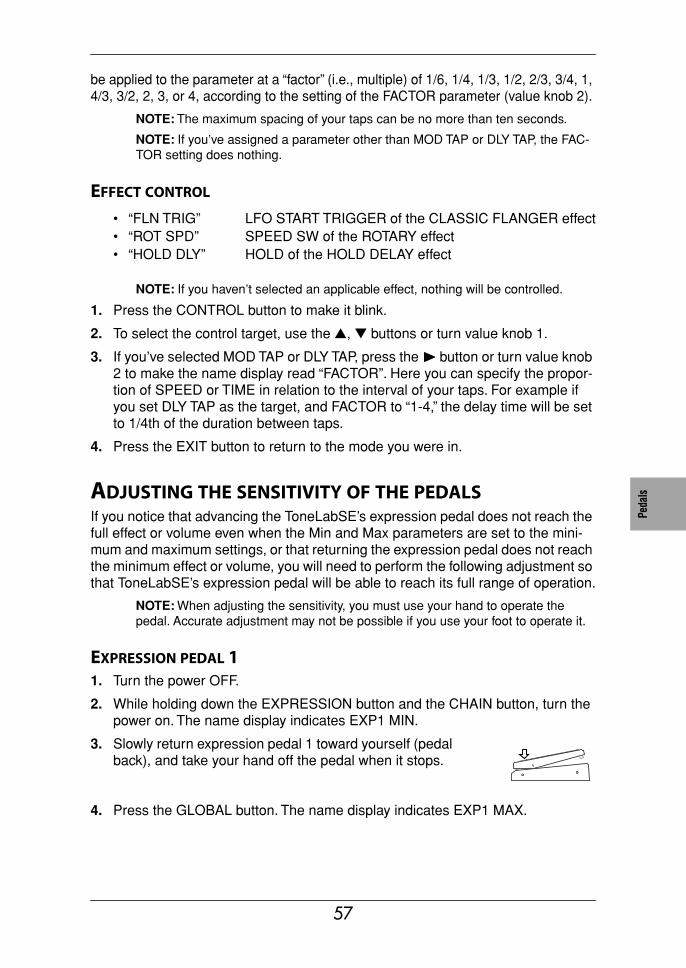
Tune
rPe
dals
MIDI
/DIG
ITAL
Facto
ryse
tting
sTr
oubl
e-sh
ootin
gSp
ec.
Prog
ram
List
be applied to the parameter at a “factor” (i.e., multiple) of 1/6, 1/4, 1/3, 1/2, 2/3, 3/4, 1, 4/3, 3/2, 2, 3, or 4, according to the setting of the FACTOR parameter (value knob 2).
NOTE: The maximum spacing of your taps can be no more than ten seconds.
NOTE: If you’ve assigned a parameter other than MOD TAP or DLY TAP, the FAC-TOR setting does nothing.
EFFECT CONTROL
NOTE: If you haven’t selected an applicable effect, nothing will be controlled.
1. Press the CONTROL button to make it blink.
2. To select the control target, use the ▲, ▼ buttons or turn value knob 1.
3. If you’ve selected MOD TAP or DLY TAP, press the ®®®® button or turn value knob 2 to make the name display read “FACTOR”. Here you can specify the propor-tion of SPEED or TIME in relation to the interval of your taps. For example if you set DLY TAP as the target, and FACTOR to “1-4,” the delay time will be set to 1/4th of the duration between taps.
4. Press the EXIT button to return to the mode you were in.
ADJUSTING THE SENSITIVITY OF THE PEDALSIf you notice that advancing the ToneLabSE’s expression pedal does not reach the full effect or volume even when the Min and Max parameters are set to the mini-mum and maximum settings, or that returning the expression pedal does not reach the minimum effect or volume, you will need to perform the following adjustment so that ToneLabSE’s expression pedal will be able to reach its full range of operation.
NOTE: When adjusting the sensitivity, you must use your hand to operate the pedal. Accurate adjustment may not be possible if you use your foot to operate it.
EXPRESSION PEDAL 11. Turn the power OFF.
2. While holding down the EXPRESSION button and the CHAIN button, turn the power on. The name display indicates EXP1 MIN.
3. Slowly return expression pedal 1 toward yourself (pedal back), and take your hand off the pedal when it stops.
4. Press the GLOBAL button. The name display indicates EXP1 MAX.
• “FLN TRIG” LFO START TRIGGER of the CLASSIC FLANGER effect• “ROT SPD” SPEED SW of the ROTARY effect• “HOLD DLY” HOLD of the HOLD DELAY effect
57
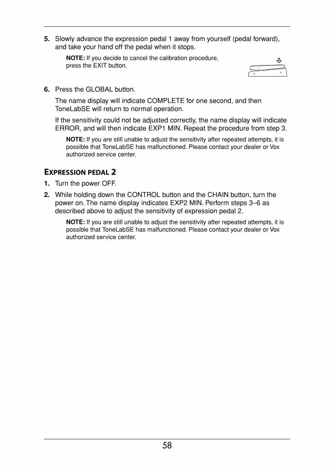
5. Slowly advance the expression pedal 1 away from yourself (pedal forward), and take your hand off the pedal when it stops.
NOTE: If you decide to cancel the calibration procedure, press the EXIT button.
6. Press the GLOBAL button.
The name display will indicate COMPLETE for one second, and then ToneLabSE will return to normal operation.
If the sensitivity could not be adjusted correctly, the name display will indicate ERROR, and will then indicate EXP1 MIN. Repeat the procedure from step 3.
NOTE: If you are still unable to adjust the sensitivity after repeated attempts, it is possible that ToneLabSE has malfunctioned. Please contact your dealer or Vox authorized service center.
EXPRESSION PEDAL 21. Turn the power OFF.
2. While holding down the CONTROL button and the CHAIN button, turn the power on. The name display indicates EXP2 MIN. Perform steps 3–6 as described above to adjust the sensitivity of expression pedal 2.
NOTE: If you are still unable to adjust the sensitivity after repeated attempts, it is possible that ToneLabSE has malfunctioned. Please contact your dealer or Vox authorized service center.
58
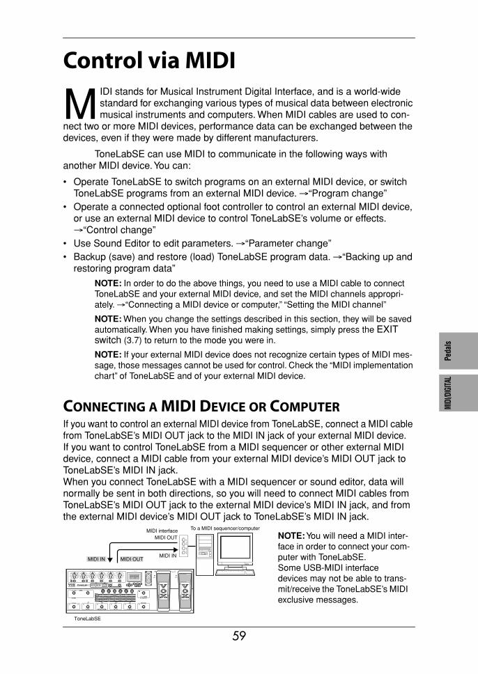
Tune
rPe
dals
MIDI
/DIG
ITAL
Facto
ryse
tting
sTr
oubl
e-sh
ootin
gSp
ec.
Prog
ram
List
Control via MIDIIDI stands for Musical Instrument Digital Interface, and is a world-wide standard for exchanging various types of musical data between electronic musical instruments and computers. When MIDI cables are used to con-
nect two or more MIDI devices, performance data can be exchanged between the devices, even if they were made by different manufacturers.
ToneLabSE can use MIDI to communicate in the following ways with another MIDI device. You can:
• Operate ToneLabSE to switch programs on an external MIDI device, or switch ToneLabSE programs from an external MIDI device. →“Program change”
• Operate a connected optional foot controller to control an external MIDI device, or use an external MIDI device to control ToneLabSE’s volume or effects. →“Control change”
• Use Sound Editor to edit parameters. →“Parameter change”• Backup (save) and restore (load) ToneLabSE program data. →“Backing up and
restoring program data”
NOTE: In order to do the above things, you need to use a MIDI cable to connect ToneLabSE and your external MIDI device, and set the MIDI channels appropri-ately. →“Connecting a MIDI device or computer,” “Setting the MIDI channel”
NOTE: When you change the settings described in this section, they will be saved automatically. When you have finished making settings, simply press the EXIT switch (3.7) to return to the mode you were in.
NOTE: If your external MIDI device does not recognize certain types of MIDI mes-sage, those messages cannot be used for control. Check the “MIDI implementation chart” of ToneLabSE and of your external MIDI device.
CONNECTING A MIDI DEVICE OR COMPUTERIf you want to control an external MIDI device from ToneLabSE, connect a MIDI cable from ToneLabSE’s MIDI OUT jack to the MIDI IN jack of your external MIDI device.If you want to control ToneLabSE from a MIDI sequencer or other external MIDI device, connect a MIDI cable from your external MIDI device’s MIDI OUT jack to ToneLabSE’s MIDI IN jack.When you connect ToneLabSE with a MIDI sequencer or sound editor, data will normally be sent in both directions, so you will need to connect MIDI cables from ToneLabSE’s MIDI OUT jack to the external MIDI device’s MIDI IN jack, and from the external MIDI device’s MIDI OUT jack to ToneLabSE’s MIDI IN jack.
M
ToneLabSE
MIDI IN MIDI OUTMIDI IN
MIDI OUT
To a MIDI sequencer/computerMIDI interfaceNOTE: You will need a MIDI inter-face in order to connect your com-puter with ToneLabSE.Some USB-MIDI interface devices may not be able to trans-mit/receive the ToneLabSE’s MIDI exclusive messages.
59
SETTING THE MIDI CHANNEL (GLOBAL “MIDI CH”)In order to exchange data with an external MIDI device, ToneLabSE’s MIDI chan-nel must match the MIDI channel of your external MIDI device. Here’s how to set the MIDI channel.
1. Press the GLOBAL button (3.4).
2. The name display (3.8) will show “MIDI CH.” If a different parameter is selected, press the √√√√, ®®®® buttons (3.2) to change the display.
3. Use the value knob 3 (2.2) or the ▲, ▼ buttons (3.1) to set ToneLabSE’s MIDI channel.
4. Set the MIDI channel of your connected external MIDI device.For details on how to set the MIDI channel of your external MIDI device, refer to its owner’s manual.
PROGRAM CHANGE (GLOBAL “PCHG OUT”)When you switch programs on ToneLabSE, a program change message is trans-mitted from the MIDI OUT jack, causing an external MIDI device to switch pro-grams. Similarly, when ToneLabSE receives a program change message, its program will switch automatically. Here’s how you can specify whether a program change message will be transmitted from the MIDI OUT jack when you switch pro-grams on ToneLabSE.
NOTE: Program change numbers not used by ToneLabSE will be ignored. For details on the range of program change numbers used by ToneLabSE, refer to End of this manual.
1. Press the GLOBAL button (3.4).
2. Press the √√√√, ®®®® buttons (3.2) to make the name display (3.8) show “PCHG OUT.”
3. Specify whether program change messages will be transmitted. Use value knob 6 (2.2) or the ▲, ▼ buttons (3.1) to make the desired setting.
“OFF”: Program change messages will not be transmitted.“On”: Program change messages will be transmitted.
CONTROL CHANGE (GLOBAL “CCHG I/O”)When you operate the EXPRESSION pedal 1, Expression pedal 2, or Control pedal of the ToneLabSE, control change messages will be transmitted. This means that func-tions for the corresponding control change numbers on an external MIDI device can be controlled in realtime.Similarly, when ToneLabSE receives control change messages from an external MIDI device, it will be controlled in the same way as if its own foot controller were operated.For a list of the functions that can be controlled from an external MIDI device, refer to step 4.Here you can specify whether ToneLabSE will transmit and receive control change messages.
60
Tune
rPe
dals
MIDI
/DIG
ITAL
Facto
ryse
tting
sTr
oubl
e-sh
ootin
gSp
ec.
Prog
ram
List
1. Press the GLOBAL button (3.4).
2. Press the √√√√, ®®®® buttons (3.2) to make the name display (3.8) read “CCHG I/O.”
3. Specify whether all control change messages will be transmitted or received. Use value knob 6 (2.2) or the ▲, ▼ buttons (3.1) to make your choice.“On” allows transmitting and receiving. “OFF” disables transmitting and receiv-ing.
NOTE: If this setting is “OFF,” no control change messages will be transmitted or received even if you specify individual control change numbers in step 4.
4. Simultaneously press both √√√√, ®®®® buttons (3.2) to access the screen where you can set control numbers individually. Use the √√√√, ®®®® buttons to select each con-troller.
The controllers will be selected in the following order.
5. For each controller, specify whether ToneLabSE will transmit and receive control change messages. If you want ToneLabSE to transmit and receive messages for a controller, specify the control change number. Select a controller, and use value knob 6 (2.2) or the ▲, ▼ buttons (3.1) to make the desired setting.
“OFF”: Control change messages will not be transmitted or received.
“CC00”–“CC95”: When you operate a controller, messages of the specified control change number 00–95 will be transmitted. Similarly, ToneLabSE will be controlled when it receives messages of the same control change number from an external MIDI device.
6. To return to the screen where you specify transmit or receive for all control change messages, press both √√√√, ®®®® buttons (3.2) simultaneously.
PARAMETER CHANGE (GLOBAL “SYEX OUT”)When you operate ToneLabSE’s knobs or buttons to edit the value of a parameter, system exclusive such as parameter changes are transmitted.If you want ToneLabSE’s parameters to be transmitted to an external device, turn the “SYEX OUT” setting “On.” Normally, you will turn “SYEX OUT” on when using the Sound Editor.This setting specifies whether ToneLabSE will transmit parameter changes.
“EXP1 PDL” Expression pedal 1 control“EXP2 PDL” Expression pedal 2 control“CTRL PDL” Control pedal on/off“VOL PDL”: VOLUME pedal control“TAP SW”: TAP switch on/off“PEDAL FX”: PEDAL effect on/off“MOD FX”: MODULATION effect on/off“DELAY FX”: DELAY effect on/off“REVRB FX”: REVERB effect on/off“INSRT FX” External effect on/off“A/B CH” Channel A/B
61
1. Press the GLOBAL button (3.4).
2. Press the √√√√, ®®®® buttons (3.2) to make the name display (3.8) read “SYEX OUT.”
3. Specify whether parameter change messages will be transmitted. Use value knob 3 (2.2) or the ▲, ▼ buttons (3.1) to make your choice.
NOTE: When ToneLabSE receives parameter changes or other system exclusive messages, its parameters, modes, or program numbers will change — regardless of the “SYEX OUT” setting.
BACKING UP AND RESTORING PROGRAM DATA (GLOBAL “DUMP CUR,” DUMP ALL”)All of ToneLabSE’s data (including its programs) can be transmitted and received in the form of system exclusive messages. Exchanging this type of data with an exter-nal device via system exclusive messages is known as a “data dump.” By perform-ing a data dump, ToneLabSE programs you created can be backed up (saved) on an external device such as a MIDI data filer or a sequencer that is able to transmit and receive system exclusive messages. Then when necessary, you can re-trans-mit that data back to ToneLabSE to restore it. This provides a way for you to orga-nize large numbers of programs. You can also use this method to copy program data between two connected ToneLabSEs.You can transfer program data in one of two ways; one program at a time, or all pro-grams at once. When you transmit all programs at once, all of ToneLabSE’s data will also be transmitted, including Dump settings and MIDI settings.
NOTE: You can transmit data dumps regardless of the “SYEX OUT” setting. In fact, if you want to transfer program data between two ToneLabs, we recommend that you turn the “SYEX OUT” setting “OFF.” If “SYEX OUT” is “On,” operating the knobs or other controls may change the parameters of the other ToneLabSE in unintended ways.
BACKING UP
1. Connect ToneLabSE’s MIDI OUT to the MIDI IN of the device that will receive the data dump.
2. If you want to transmit only one program, use Program Select Mode to select the program you want to transmit.
3. Press the GLOBAL button (3.4).
4. Press the √√√√, ®®®® buttons (3.2) to make the name display (3.8) read “DUMP CUR” or “DUMP ALL.”
“DUMP CUR” (Dump current program data): The data of the currently selected program will be dumped. If you are editing the program (and have not yet saved it), the current settings will be transmitted.
“OFF”: Parameter change messages will not be transmitted.“On”: Parameter change messages will be transmitted.
62
Tune
rPe
dals
MIDI
/DIG
ITAL
Facto
ryse
tting
sTr
oubl
e-sh
ootin
gSp
ec.
Prog
ram
List
“DUMP ALL” (Dump all data): All of the ToneLabSE’s data will be dumped.
5. Put the receiving device in a mode in which it can record the data dump.
NOTE: For details, refer to the owner’s manual of the device that will receive the data dump.
6. Press ToneLabSE’s WRITE button (3.6) to begin transmitting. When transmit-ting is completed, the display will indicate “COMPLETE,” and you will return to the screen of step 4. (While “DUMP ALL” is being transmitted, the display will indicate “SEND.”)
NOTE: While data is being transmitted, do not touch the buttons or knobs of ToneLabSE or its foot controller, and never turn off the power.
RESTORING
1. Connect the transmitting device’s MIDI OUT to ToneLabSE’s MIDI IN.
2. Set the transmitting MIDI device and ToneLabSE to the same MIDI channel. If ToneLabSE will be receiving data that was previously transmitted to the exter-nal MIDI device, select the same MIDI channel as was used when transmitting.
3. Transmit the data dump from the external device.While ToneLabSE is receiving all data, its display will indicate “RECEIVE.” When reception has been successfully completed, it will indicate “COM-PLETE.” If an error occurs, the display will indicate “ERROR”; in this case, try transmitting the data again.
NOTE: For details, refer to the owner’s manual of the device that will be transmit-ting the data dump.
NOTE: While data is being transmitted, don't touch the ToneLabSE's buttons, ped-als, or knobs, and never turn off the power.
4. If you received data for a single program, select the save-destination bank and program, and save the data. (p.22)
NOTE: The program data will not be written into ToneLabSE’s program memory unless you store it.If you received data in Manual Mode, settings other than for the amp section will be overwritten automatically, so you don’t need to store the settings yourself. (Since the settings of the amp section are determined by the physical positions of the selectors and controllers, they will not change.)
HINT: If ToneLabSE receives all data, all of its data will be overwritten automatically. However, the data currently being edited (i.e., the edit buffer) will not be affected.
63
Restoring the Factory Preset Programs
ere’s how you can restore ToneLabSE’s programs and all its other settings to the state in which it was shipped from the factory.
NOTE: Executing this procedure will erase all the programs you created and saved in ToneLabSE, and will load the factory-set programs. MIDI settings will also be ini-tialized. If there are any settings you want to keep, you should first use the data dump function to back them up, or use the “Program sheet” (the fold-out inside the back cover of this manual) to write down your settings.
1. While holding down the three buttons ▲, ▼ (3.1), and EXIT switch (3.7), press the STANDBY button to turn on the power.The bank display (5.1) “P” and the LED 1–4 buttons (6.2) will blink, and the name display (3.8) will ask “RELOAD?” Release the three buttons you were holding down.
2. If at this point you decide that you really don’t want to execute this operation, you can press the EXIT switch.
3. Press the WRITE button (3.6). The name display (3.8) will show “LOADING,” and the factory-set data will begin being reloaded.When reloading has been completed, the name display will indicate “COM-PLETE,” and ToneLabSE will automatically switch to Program Select Mode.
NOTE: Never turn off the power while this reload operation is occurring.
H
64
Tune
rPe
dals
MIDI
/DIG
ITAL
Facto
ryse
tting
sTr
oubl
e-sh
ootin
gSp
ec.
Prog
ram
List
Troubleshootingf you suspect a malfunction, please check the following points first. If this does not resolve the problem, please contact your dealer or Vox authorized service center.
1. The amp isn’t powering up when the STANDBY switch is “on”
• Is the AC/AC power supply connected to the rear panel ~AC9V jack?• Is the AC/AC power supply plugged into an AC outlet?• Is the STANDBY switched on?• Could the AC/AC power supply be damaged?
2. There’s no sound• Is your guitar turned up?• Are both ends of your guitar cable plugged into the correct jacks?• Is your guitar cable working?• Could the rear panel OUTPUT LEVEL knob be turned down?• Check the GAIN, TREBLE, MIDDLE, BASS, VR GAIN, and CH VOLUME set-
tings. For some amp types, you might not hear any sound if the TREBLE, MID-DLE, and BASS settings are turned down – just like the circuitry on the original amp!If you are using a pedal effect, check the DRIVE [1] and LEVEL [3] settings as well.
• Could an expression pedal be at the minimum position with a parameter such as DRIVE, LEVEL, VOLUME, GAIN, or VR GAIN assigned to it?
• Could you have activated the Mute function? Press the FX ON/OFF (TUNER) pedal to defeat muting.
3. You can't hear any effects even though they're dialed in...• Are the effect LEDs lit?
If an LED is dark, the corresponding effect is off.Press the MODE select button to turn on the effect.
• Could the modulation “DEPTH” or the delay/reverb “MIX” be set to a low value? Press the MODE select button to select an effect and use the value knobs to adjust the appropriate parameters.
• Could the effect be bypassed?If so, press the FX ON/OFF pedal to cancel bypass.
I
65

4. You’re using the ACOUSTIC pedal effect and getting nasty high frequency distortion.
• Could the Drive setting be excessively high?• Are you using a very high output humbucking pickup?
Either turn down the volume of your guitar, the Amp GAIN or Treble setting for the pedal.
5. The sound connected to your guitar amp is distorted, or sounds wrong.
• Could “OUT SEL” switch be set to “Ln” (LINE)?• Could LEVEL be raised excessively?→Make the correct settings as described in Basic Connections.
66
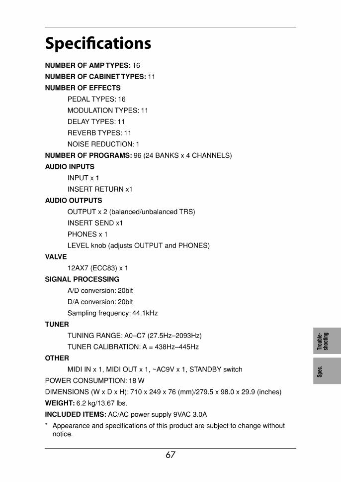
Tune
rPe
dals
MIDI
/DIG
ITAL
Facto
ryse
tting
sTr
oubl
e-sh
ootin
gSp
ec.
Prog
ram
List
SpecificationsNUMBER OF AMP TYPES: 16
NUMBER OF CABINET TYPES: 11
NUMBER OF EFFECTS
PEDAL TYPES: 16
MODULATION TYPES: 11
DELAY TYPES: 11
REVERB TYPES: 11
NOISE REDUCTION: 1
NUMBER OF PROGRAMS: 96 (24 BANKS x 4 CHANNELS)
AUDIO INPUTS
INPUT x 1
INSERT RETURN x1
AUDIO OUTPUTS
OUTPUT x 2 (balanced/unbalanced TRS)
INSERT SEND x1
PHONES x 1
LEVEL knob (adjusts OUTPUT and PHONES)
VALVE
12AX7 (ECC83) x 1
SIGNAL PROCESSING
A/D conversion: 20bit
D/A conversion: 20bit
Sampling frequency: 44.1kHz
TUNER
TUNING RANGE: A0–C7 (27.5Hz–2093Hz)
TUNER CALIBRATION: A = 438Hz–445Hz
OTHER
MIDI IN x 1, MIDI OUT x 1, ~AC9V x 1, STANDBY switch
POWER CONSUMPTION: 18 W
DIMENSIONS (W x D x H): 710 x 249 x 76 (mm)/279.5 x 98.0 x 29.9 (inches)
WEIGHT: 6.2 kg/13.67 lbs.
INCLUDED ITEMS: AC/AC power supply 9VAC 3.0A
* Appearance and specifications of this product are subject to change without notice.
67
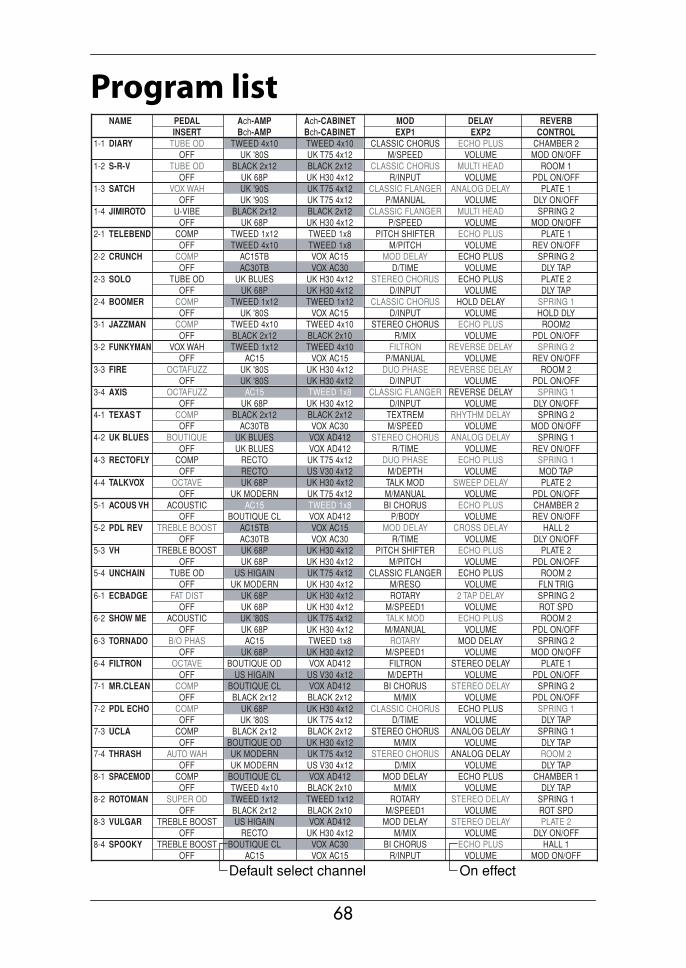
68
Program listNAME Ach-AMP Ach-CABINET MOD DELAY REVERBPEDAL
Bch-AMP Bch-CABINET EXP1 EXP2 CONTROLINSERT1-1 DIARY TWEED 4x10 TWEED 4x10 CLASSIC CHORUS ECHO PLUS CHAMBER 2TUBE OD
UK '80S UK T75 4x12 M/SPEED VOLUME MOD ON/OFFOFF1-2 S-R-V BLACK 2x12 BLACK 2x12 CLASSIC CHORUS MULTI HEAD ROOM 1TUBE OD
UK 68P UK H30 4x12 R/INPUT VOLUME PDL ON/OFFOFF1-3 SATCH UK '90S UK T75 4x12 CLASSIC FLANGER ANALOG DELAY PLATE 1VOX WAH
UK '90S UK T75 4x12 P/MANUAL VOLUME DLY ON/OFFOFF1-4 JIMIROTO BLACK 2x12 BLACK 2x12 CLASSIC FLANGER MULTI HEAD SPRING 2U-VIBE
UK 68P UK H30 4x12 P/SPEED VOLUME MOD ON/OFFOFF2-1 TELEBEND TWEED 1x12 TWEED 1x8 PITCH SHIFTER ECHO PLUS PLATE 1COMP
TWEED 4x10 TWEED 1x8 M/PITCH VOLUME REV ON/OFFOFF2-2 CRUNCH AC15TB VOX AC15 MOD DELAY ECHO PLUS SPRING 2COMP
AC30TB VOX AC30 D/TIME VOLUME DLY TAPOFF2-3 SOLO UK BLUES UK H30 4x12 STEREO CHORUS ECHO PLUS PLATE 2TUBE OD
UK 68P UK H30 4x12 D/INPUT VOLUME DLY TAPOFF2-4 BOOMER TWEED 1x12 TWEED 1x12 CLASSIC CHORUS HOLD DELAY SPRING 1COMP
UK '80S VOX AC15 D/INPUT VOLUME HOLD DLYOFF3-1 JAZZMAN TWEED 4x10 TWEED 4x10 STEREO CHORUS ECHO PLUS ROOM2COMP
BLACK 2x12 BLACK 2x10 R/MIX VOLUME PDL ON/OFFOFF3-2 FUNKYMAN TWEED 1x12 TWEED 4x10 FILTRON REVERSE DELAY SPRING 2VOX WAH
AC15 VOX AC15 P/MANUAL VOLUME REV ON/OFFOFF3-3 FIRE UK '80S UK H30 4x12 DUO PHASE REVERSE DELAY ROOM 2OCTAFUZZ
UK '80S UK H30 4x12 D/INPUT VOLUME PDL ON/OFFOFF3-4 AXIS AC15 TWEED 1x8 CLASSIC FLANGER REVERSE DELAY SPRING 1OCTAFUZZ
UK 68P UK H30 4x12 D/INPUT VOLUME DLY ON/OFFOFF4-1 TEXAS T BLACK 2x12 BLACK 2x12 TEXTREM RHYTHM DELAY SPRING 2COMP
AC30TB VOX AC30 M/SPEED VOLUME MOD ON/OFFOFF4-2 UK BLUES UK BLUES VOX AD412 STEREO CHORUS ANALOG DELAY SPRING 1BOUTIQUE
UK BLUES VOX AD412 R/TIME VOLUME REV ON/OFFOFF4-3 RECTOFLY RECTO UK T75 4x12 DUO PHASE ECHO PLUS SPRING 1COMP
RECTO US V30 4x12 M/DEPTH VOLUME MOD TAPOFF4-4 TALKVOX UK 68P UK H30 4x12 TALK MOD SWEEP DELAY PLATE 2OCTAVE
UK MODERN UK T75 4x12 M/MANUAL VOLUME PDL ON/OFFOFF5-1 ACOUS VH AC15 TWEED 1x8 BI CHORUS ECHO PLUS CHAMBER 2ACOUSTIC
BOUTIQUE CL VOX AD412 P/BODY VOLUME REV ON/OFFOFF5-2 PDL REV AC15TB VOX AC15 MOD DELAY CROSS DELAY HALL 2TREBLE BOOST
AC30TB VOX AC30 R/TIME VOLUME DLY ON/OFFOFF5-3 VH UK 68P UK H30 4x12 PITCH SHIFTER ECHO PLUS PLATE 2TREBLE BOOST
UK 68P UK H30 4x12 M/PITCH VOLUME PDL ON/OFFOFF5-4 UNCHAIN US HIGAIN UK T75 4x12 CLASSIC FLANGER ECHO PLUS ROOM 2TUBE OD
UK MODERN UK H30 4x12 M/RESO VOLUME FLN TRIGOFF6-1 ECBADGE UK 68P UK H30 4x12 ROTARY 2 TAP DELAY SPRING 2FAT DIST
UK 68P UK H30 4x12 M/SPEED1 VOLUME ROT SPDOFF6-2 SHOW ME UK '80S UK T75 4x12 TALK MOD ECHO PLUS ROOM 2ACOUSTIC
UK 68P UK H30 4x12 M/MANUAL VOLUME PDL ON/OFFOFF6-3 TORNADO AC15 TWEED 1x8 ROTARY MOD DELAY SPRING 2B/O PHAS
UK 68P UK H30 4x12 M/SPEED1 VOLUME MOD ON/OFFOFF6-4 FILTRON BOUTIQUE OD VOX AD412 FILTRON STEREO DELAY PLATE 1OCTAVE
US HIGAIN US V30 4x12 M/DEPTH VOLUME PDL ON/OFFOFF7-1 MR.CLEAN BOUTIQUE CL VOX AD412 BI CHORUS STEREO DELAY SPRING 2COMP
BLACK 2x12 BLACK 2x12 M/MIX VOLUME PDL ON/OFFOFF7-2 PDL ECHO UK 68P UK H30 4x12 CLASSIC CHORUS ECHO PLUS SPRING 1COMP
UK '80S UK T75 4x12 D/TIME VOLUME DLY TAPOFF7-3 UCLA BLACK 2x12 BLACK 2x12 STEREO CHORUS ANALOG DELAY SPRING 1COMP
BOUTIQUE OD UK H30 4x12 M/MIX VOLUME DLY TAPOFF7-4 THRASH UK MODERN UK T75 4x12 STEREO CHORUS ANALOG DELAY ROOM 2AUTO WAH
UK MODERN US V30 4x12 D/MIX VOLUME DLY TAPOFF8-1 SPACEMOD BOUTIQUE CL VOX AD412 MOD DELAY ECHO PLUS CHAMBER 1COMP
TWEED 4x10 BLACK 2x10 M/MIX VOLUME DLY TAPOFF8-2 ROTOMAN TWEED 1x12 TWEED 1x12 ROTARY STEREO DELAY SPRING 1SUPER OD
BLACK 2x12 BLACK 2x10 M/SPEED1 VOLUME ROT SPDOFF8-3 VULGAR US HIGAIN VOX AD412 MOD DELAY STEREO DELAY PLATE 2TREBLE BOOST
RECTO UK H30 4x12 M/MIX VOLUME DLY ON/OFFOFF8-4 SPOOKY BOUTIQUE CL VOX AC30 BI CHORUS ECHO PLUS HALL 1TREBLE BOOST
AC15 VOX AC15 R/INPUT VOLUME MOD ON/OFFOFF
Default select channel On effect
69
IndexNumerics1OCTAVE 372OCTAVE 37
AAC15 25AC15TB 26AC30 26AC30TB 27ACOUSTIC 36AMP Models 23ATTACK 36, 37AUTO WAH 36automatic chromatic
tuner 51
BBacking Up 62BASS 23, 36BLACK 2x10 (BLK
2X10) 32BLACK 2x12 (BLK
2X12) 30, 33BODY 36BOUTIQUE CL (BTQ
CL) 30BOUTIQUE OD (BTQ
OD) 30
CCabinet 32CABINET Models 32Calibrating 52CC 61CCHG I/O 60CH VOLUME 24CHAIN 21CLOSE 36COMP 35Connection 13, 59Control Change 60Creating Program 19
DDELAY 45DELAY EFFECTS 45DELAY FX 61DEPTH 37DIRECT 37DUMP ALL 63DUMP CUR 62
EEffect On/Off mode 16EXP PDL 61expression pedals 53
FFAT OD 38FUZZ 39
GGAIN 24
HHow the original amps
work 24
LLEVEL 36
MMASTER VOLUME 24MIDDLE 23MIDI 59MIDI CH 60MIDI Channel 60MIX 37Mix any amp model to
any cabinet model 34
MOD EFFECTS 39MOD FX 61
NNaming 21
OOCTAVE 37OPEN 36Orginal tone controls
23Original Value 22
PParameter Change 61PCHG OUT 60pedal 36PEDAL EFFECTS 35PEDAL FX 61POLARITY 36PRESENCE 23Program Change 60
Program Select mode 16
RRECTO 29RELOAD? 64RENAME 21Restoring 63Restoring the Factory
Preset 64REVERB EFFECTS
48REVRB FX 61
SSENS 36SENSE 36Silent Tuning mode 51Sound Editor 2, 61SPEED 37Storing 22SYEX OUT 61
TTAP SW 61TREBLE 23, 36TREBLE BOOST
(TREB BST) 38TUBE OD 38Tuner 51TWEED 1x12 (TWD
1X12) 31, 32TWEED 4x10 (TWD
4X10) 31, 32
UUK ’80s 28UK ’90s 29UK 68P 28UK BLUES 28UK H30 4x12 (UK H30)
33UK MODERN (UK
MODRN) 29UK T75 4x12 (UK T75)
33US HIGAIN (US HI-G)
29US V30 4x12 (US V30)
33U-VIBE 37
Vvalve cover 10Valve Reactor 2VOL PDL 61VOX AC15 (AC15) 33VOX AC30 (AC30) 33VOX AD412 (AD412)
33VOX WAH 36VR GAIN 24
WWah pedal 36WRITE 22
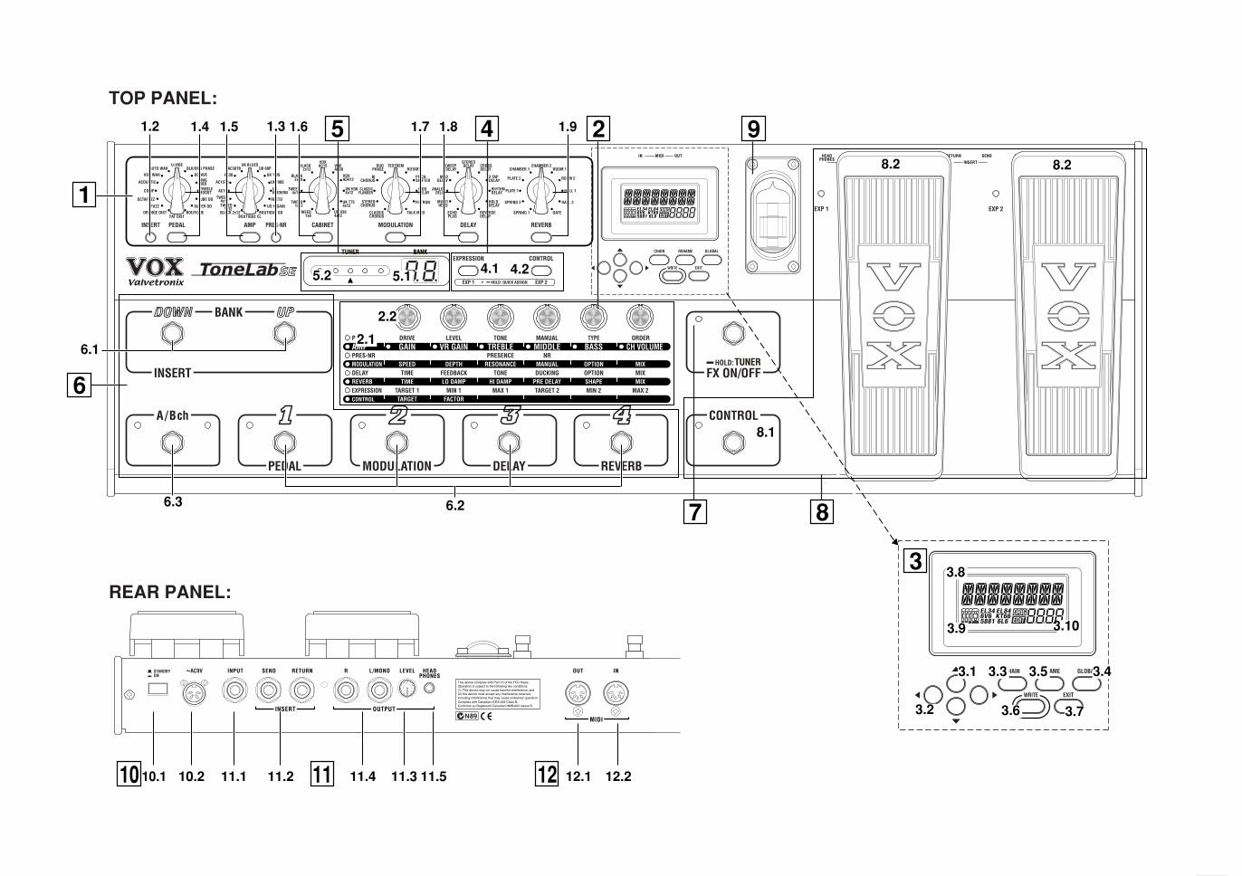
1.2 1.4
6.1
6.2
8.2 8.2
8.1
6.3
2.2
2.1
5.2 5.1 4.1 4.2
3.1 3.3 3.5 3.4
3.6 3.7
3.8
3.9 3.10
3.2
11.1 11.2 11.4 11.3 11.510.1 10.2
2
7
3
4
1
12.212.110 11 12
6
8
951.31.5 1.6 1.7 1.8 1.9
TOP PANEL:
REAR PANEL:

2003 VOX AM
Date : 2003. 9.1
ToneLabS
E
Mem
orized
[VO
X V
alvetronix]
Param
eter Control
Program
Data D
ump
Notes
*P
: Transmitted if G
LOB
AL “P
CH
G O
UT
” is On.
*C: Transm
itted and received according to the setting of each controller if GLO
BA
L “CC
HG
I/O” is O
n.*E
: Transmitted if G
LOBAL “SYEX O
UT” is On. (Responses to Request m
essages are always transmitted regardless of the “SYEX O
UT” setting.)*1: In addition to m
essages specifically for this device, Device Inquiry is also supported.
Effect C
ontrol0–95
MID
I Implem
entation Chart
Basic
Channel
Default
Changed
Aftertouch
Pitch B
end
Polyphonic (K
ey)M
onophonic (Channel)
Program
C
hangeV
ariable Range
System
Real T
ime
Clock
Com
mand
System
Exclusive
System
Com
mon
Song P
ositionS
ong Select
Tune
Mode 1: O
MN
I ON
, PO
LYM
ode 2: OM
NI O
N, M
ON
O: Y
es
Mode 3: O
MN
I OF
F, P
OLY
Mode 4: O
MN
I OF
F, M
ON
O: N
o
Aux
Messages
Local On/O
ffA
ll Notes O
ffA
ctive Sense
Reset
Velocity
Note O
nN
ote Off
Note
Num
ber:T
rue Voice
Mode
Mem
orizedM
essagesA
ltered
Control
Change
Fu
nctio
nT
ransm
ittedR
ecog
nized
Rem
arks
Consult your local K
org distributor for more inform
ation on MID
I IMP
LEM
EN
TATIO
N.
E1
2003 VOX AMPLIFICATION LTD. Printed in China
Ow
ner's M
anu
al