Embed Size (px)
DESCRIPTION
Press tools Designs
Citation preview

TOOL DESIGN DATA BOOK
FOR
DIPLOMA IN MECHANICAL ENGINEERING (TOOL & DIE)
COURSE CODE 1220
DIRECTORATE OF TECHNICAL EDUCATIONGOVERNMENT OF TAMILNADU

Tool Design Data Book Page 2
DIRECTORATE OF TECHNICAL EDUCATION
GUINDY, CHENNAI – 25
TOOL DESIGN DATA BOOK
1. This book can be used for Board Examination by the
Diploma in Mechanical Engineering (Tool & Die) students
for the Tool Design subject.
2. The Use of this data book ( Institutional copy) Indian
Standard specifications listed in Table 6.34 of this data
book and any other related Indian standard specifications
is permitted in the Board Examination for the subject
22254 - Tool Design and Drawing

Tool Design Data Book Page 3
CONTENTSSL.NO TOPIC PAGE
NO.1. Material Properties 1
2. Sheet material SWG to mm & inch conversion 2
3. Data for stamping dies
Formulae 3
Strip layout 4
Die plate design data 5
Stripper design data 10
Punch design details 12
Punch holder data 15
Pilots 16
Finger stops 17
Automatic stops 18
Fasteners - Screws & dowels 21
Die set 23
Press data 27
Shut height 28
Punch and die materials & Heat treatment 29
Centre of Pressure 34
Spring design data 36

Tool Design Data Book Page 4
4. Data for bending dies 61
5. Data for drawing dies 66
6. Data for gauge Design
ISO System of limits and fits – tolerances & deviations 70
Reference Indian standard specifications for gauge design 102
7. Jigs & fixtures
Guidelines for selection of locators and clamps 103
Locating pins 104
Clamps 106
Jig feet & buttons 108
Jig bushes 110
Screws & nuts 113
Pressure pads 117
Spherical & ‘C’ Washers 118
Wing nuts 119
8. Unit Conversion tables 120

Tool Design Data Book Page 1
Table 1 - MATERIAL PROPERTIES
S.No MATERIALSHEAR STRENGTH
N/mm2
ULTIMATE TENSILE
STRENGTH
N/mm2
1. Stainless steel 539.70 719.6
2. Steel 0.1% carbon ( soft) 346.95 462.6
3. Steel 0.25%carbon ( mild) 385.5 514
4. Steel 0.5% carbon 539.70 719.6
5. Steel 0.75% carbon 616.8 822.4
6. Steel 1% carbon 655.35 873.8
7. Steel 1.2% carbon ( not tempered) 724.7 966.2
8. Steel 1.25% carbon( tempered hot) 1464.89 1953.18
9. Aluminium soft sheet 115.65 154.2
10. Aluminium half hard sheet 146.49 195.32
11. Aluminium hard sheet 192.75 257
12. Brass soft sheet 231.29 308.38
13. Brass half hard sheet 269.85 359.8
14. Brass hard sheet 308.40 411.20
15. Copper rolled 215.88 287.84
16. Cupro nickel 308.4 411.20
17. Duralumin soft sheet 231.29 308.39
18. Duralumin treated and cold rolled 308.10 410.80
19. Fibre hard 185.04 246.72
20. Lead 30.84 41.12
21. Leather 54 72
22. Oak ( wood) 54 72
23. Tin rolled sheet 38.55 51.4
24. Tin coated steel sheet 385.5 514
25. Zinc rolled sheet 138 184
26. Zinc hard rolled 154.20 205.6
27. Silver 231.29 308.38
28. Paper using hollow dies 23.13 30.84TOOL DESIG
N DATA B
OOK

Tool Design Data Book Page 2
Table 2 - Sheet material SWG to mm & inch conversion
SWG inches Mm SWG inches Mm SWG inches mm
7/0 0.500 12.700 13 0.092 2.34 32 0.0108 0.27
6/0 0.464 11.79 14 0.080 2.03 33 0.0100 0.25
5/0 0.432 10.97 15 0.072 1.83 34 0.0092 0.23
4/0 0.400 10.16 16 0.064 1.63 35 0.0084 0.21
3/0 0.372 9.45 17 0.056 1.42 36 0.0076 0.19
2/0 0.348 8.84 18 0.048 1.22 37 0.0068 0.17
1/0 0.324 8.23 19 0.040 1.02 38 0.006 0.15
1 0.300 7.62 20 0.036 0.91 39 0.0052 0.13
2 0.276 7.01 21 0.032 0.81 40 0.0048 0.12
3 0.252 6.40 22 0.028 0.71 41 0.0044 0.11
4 0.232 5.89 23 0.024 0.61 42 0.004 0.10
5 0.212 5.39 24 0.022 0.56 43 0.0036 0.09
6 0.192 4.88 25 0.020 0.51 44 0.0032 0.08
7 0.176 4.47 26 0.018 0.46 45 0.0028 0.07
8 0.160 4.06 27 0.0164 0.42 46 0.0024 0.06
9 0.144 3.66 28 0.0148 0.38 47 0.002 0.05
10 0.128 3.25 29 0.0136 0.35 48 0.0016 0.04
11 0.116 2.95 30 0.0124 0.31 49 0.0012 0.03
12 0.104 2.64 31 0.0116 0.30 50 0.001 0.02
TOOL DESIG
N DATA B
OOK

Tool Design Data Book Page 3
DATA FOR STAMPING DIES
FORMULAE:
1. Cutting force = S*P*T
Where S = Shear strength of the component material in N/mm2
P = Perimeter of the component in mm
T = Thickness of the component in mm
2. Percentage of utilization = 100XStripofArea
BlankofArea
3. Percentage of scrap = 100 – Percentage of utilization
4. Stripping Force = 10 to 20% of cutting force
5. Press Capacities = Cutting Force x 1.3
6.Compressive force on punches = comp.stress of the punch matl. X area of cross section of punch
7. Buckling Forces =π2EI/LP2
WHERE E= modulus of elasticity in GN/mm2
I=moment of inertia in mm4
Lp=length of punch in mm
8. Strip layout
Margin (or) Bridge = 1.5t where ‘t’ is the sheet metal thickness in mm
The margin or the bridge thickness can also be selected from the following table
TOOL DESIG
N DATA B
OOK

Tool Design Data Book Page 4
Table - 3.1 - DATA FOR STRIP LAYOUT
Web
length(l)
in mm
Thickness of sheet metal in mm
0.5 0.75 1 1.25 1.5 1.75 2 2.25 2.5 3 3.5 4
Margin, (S), mm
10 1.5 1.2 1 1.4 1.5 1.8 2 2 2 2 2.5 2.5
50 2 1.7 1.75 1.9 2 2.2 2.5 2.8 3 3.5 3.7 4
100 3 2.4 2 2.4 2.5 2.7 3 3.2 3.5 4 4.2 4.5
150 3.5 2.9 2.5 2.9 3 3.2 3.5 3.7 4 4.5 4.7 5
250 4 3.4 3 3.4 3.5 3.7 4 4.2 4.5 5 5.2 5.5
350 4.5 3.9 3.5 3.9 4 4.2 4.5 4.7 5 5.5 5.7 6
TOOL DESIG
N DATA B
OOK

Tool Design Data Book Page 5
DIE PLATE DESIGN DATA:
Die block thickness = 3√F Where F is cutting force in Kg.
Die block thickness and other die dimensions may also be selected from the
following table:
Table 3.2 - Recommended minimum C distance for various die hole contour and die block heights B
A BC
Minimum Distance – Die Hole To Outside Edge
Strip Thickness
0 to 1.5
1.5 to 3.1
3.1 to 4.7
4.7 to 6.3
Over 6.3
Die Block Height
24
29
35
42
48
1Smooth Die Hole Contour
(1.125 B)
27
33
39
47
54
2Inside Corners
(1.5 B)
36
44
53
63
72
3Sharp Inside Corners
(2 B)
48
58
70
84
96
TOOL DESIG
N DATA B
OOK

Tool Design Data Book Page 6
Table 3.3 - Tabulation of suggested standard die block sizes
A B C D E F G
76.2 88.9 15.8 44.4 57.1 23.8 M8 TAPPED THROUGH HOLE
76.2 127 15.8 44.4 95.2 23.8 M8 TAPPED THROUGH HOLE
101.6 101.6 15.8 69.8 69.8 23.8 M8 TAPPED THROUGH HOLE
101.6 127 15.8 69.8 95.2 23.8 M8 TAPPED THROUGH HOLE
101.6 152.4 15.8 69.8 120.6 23.8 M10 TAPPED THROUGH HOLE
127 127 19 88.9 88.9 23.8 M10 TAPPED THROUGH HOLE
127 152.4 19 88.9 114.3 23.8 M10 TAPPED THROUGH HOLE
TOOL DESIG
N DATA B
OOK

Tool Design Data Book Page 7
Table 3.4 - Tabulation of suggested standard medium size die block sizes:
A B C D E F G H
101.6 177.8 19 63.5 139.7 69.8 M10 TAPPED THROUGH HOLE 28.5
101.6 203.2 19 63.5 165.1 82.5 M10 TAPPED THROUGH HOLE 28.5
127 203.2 19 88.9 165.1 82.5 M10 TAPPED THROUGH HOLE 28.5
127 254 19 88.9 215.9 107.9 M10 TAPPED THROUGH HOLE 28.5
152.4 203.2 19 114.3 165.1 82.5 M10 TAPPED THROUGH HOLE 28.5
152.4 254 19 114.3 215.9 107.9 M10 TAPPED THROUGH HOLE 28.5
177.8 279.4 19 139.7 241.3 120.6 M10 TAPPED THROUGH HOLE 28.5
TOOL DESIG
N DATA B
OOK

Tool Design Data Book Page 8
Die land:-
Die land varies depending upon the no. of regrinding requirements (die life expectancy). But in
general die land is given as 3 to 5 mm.
Angular clearance: - Generally 1/4o to 1o angular clearance is provided. Increased die clearance
weakens the die. Angular clearance may also be selected from the following table:
Table 3.5 – Anglular clearance data
Strip thickness in mm Angular clearance per side
0 to 1.5875 1/4o
1.5875 to 4.76 1/20
4.76 to 7.9 3/40
Over 7.9 10
Soft materials require greater angular clearance than hard materials.
TOOL DESIG
N DATA B
OOK

Tool Design Data Book Page 9
Die clearance:-
Clearance per side = C *T * √ (τmax/10)
Where C= constant = 0.005 for very accurate components
=0.01 for normal component.
T= Sheet thickness in mm.
τmax = Shear strength of sheet material in N/mm2
Clearance per side can also be selected from the table given below:
Table 3.6 – Die clearance
Material Die clearance per side in percentageof sheet thickness
Mild steel 2.5%-5%
Aluminum 1.5%-3%
Brass 1.5%-3%
TOOL DESIG
N DATA B
OOK

Tool Design Data Book Page 10
STRIPPER DESIGN
STRIPPER PLATE THICKNESS = A = (W/30) +2t
Where A = Stripper plate thickness in mm
W= Width of strip in mm
t= Thickness of sheet metal in mm.
The stripper plate thickness can also be selected from the following table:
Table 3.7 – Stripper plate thickness
STRIP(thickness *width)
StripperPlatethickness (A)in mm
Note:-For design and manufacturing simplicity, the width and length of stripper isassumed same as that of the die plate
1.6x751.6x1501.6x2251.6x300
3.2x753.2x1503.2x2253.2x300
4.8x754.8x1504.8x2254.8x300
6.35x756.35x1506.35x2256.35x300
7.8x757.8x1507.8x2257.8x300
68
1014
10121416
12151820
16182022
18222426
TOOL DESIG
N DATA B
OOK

Tool Design Data Book Page 11
Table 3.8 – Clearance between Strip and Strip gudie
Strip thickness in mm clearance for hand feed in mm Clearance for automatic feed in mm
0-1.587 1.6 0.8
1.587-3.175 2.4 0.8
3.175-4.762 3.2 0.8
4.762-6.35 4.0 0.8
6.35-7.937 4.8 0.8
TOOL DESIG
N DATA B
OOK

Tool Design Data Book Page 12
PUNCH DESIGN DETAILS
Table 3.9 - Stepped Round Punch Table 3.10 – Round Punch
TOOL DESIG
N DATA B
OOK

Tool Design Data Book Page 13
Table 3.11 – Square Punch Table 3.12 – Quick change punch
TOOL DESIG
N DATA B
OOK

Tool Design Data Book Page 14
Table 3.13 – Punch Chamfered head Table 3.14 – Stepped Punch
Table 3.15 – Square Punch with shedder
TOOL DESIG
N DATA B
OOK

Tool Design Data Book Page 15
Table 3.16 - COMMONLY USED PUNCH PL ATE SIZES:-
Table 3.17 - COMMONLY USED PUNCH
PLATE SIZES
A B5050757575100100100125125125150150150150175175175
507575100125100125150125150175150175200250175225275
A B0 to 7.97.9 to 1111 to 12.712.7 to 15.815.8 to 17.417.4 to 1919 to 22.222.2 to 23.823.8 to 25.4
12.715.81922.225.428.531.734.938.1
TOOL DESIG
N DATA B
OOK

Tool Design Data Book Page 16
Table 3.18 - PILOTS
ACORN TYPE PILOTA B C D E MAT3.14.76.37.99.511.112.714.215.817.419
3.14.76.37.99.511.112.714.215.817.419
0.71.191.51.982.32.773.13.573.94.34.7
3.94.77.19.511.112.714.215.817.41922.2
2.33.14.76.37.17.99.511.111.912.714.2
D.R.D.R.D.R.D.R.D.R.D.R.D.R.D.R.D.R.D.R.D.R.
FLATTENED POINT TYPEA B C D E MAT20.622.223.825.426.928.530.131.733.334.938.1
20.622.223.825.426.928.530.131.733.334.938.1
12.713.414.215.816.617.418.21920.621.423.8
23.825.428.531.733.336.538.141.242.844.447.6
15.817.41920.622.223.825.426.928.530.131.7
Tool SteelT.ST.ST.ST.ST.ST.ST.ST.ST.ST.S
TOOL DESIG
N DATA B
OOK

Tool Design Data Book Page 17
FINGER STOPS
Table 3.19 - FINGER STOPS
AUTOMATIC STOPS
ASTRIP
THICKNESS
1SMOOTH DIE HOLE
CONTOUR
2INSIDE CORNERS
3SHARP CORNERS
FRONTSPACERWIDTH
FINGERSTOPNo.
FRONTSPACERWIDTH
FINGERSTOPNo.
FRONTSPACERWIDTH
FINGERSTOP No.
0 to 1.51.5 to 3.13.1 to 4.74.7 to 6.3Over 6.3
2532384550
12345
3845505864
678910
5056637075
1112131415
No. A B C D E F12345
3.24.86.48.09.5
6.37.99.511.112.7
16.620.624.628.532.5
37.344.451.558.765.8
1.62.43.24.04.8
46.2257.3766.9276.5086.05
678910
3.24.86.48.09.5
9.511.112.714.215.8
23.827.731.735.739.6
50.857.96572.279.3
1.62.43.24.04.8
61.3170.8680.4189.9999.56
1112131415
.3.24.86.48.09.5
9.511.112.714.215.8
36.40.444.448.452.3
63.570.673.581.388.4
1.62.43.24.04.8
74.0183.5693.11102.69112.26
TOOL DESIG
N DATA B
OOK

Tool Design Data Book Page 18
Table 3.20- AUTOMATIC STOPS
NO A B C D E F G H I J K L123456
101.6477.5965.21442.72092.9127
6.36.36.37.97.97.9
19.823.858.4160302.2441.9
8.79.510.311.111.912.7
6.36.36.37.97.97.9
119.3160241.3302.2340.3401.3
241.3281.9360.6441.9523.2604.5
4.76.37.99.511.112.7
2.33.13.14.74.74.7
3.13.93.95.55.55.5
7.1R.7.1R.7.1R.8.7R.10.3R.11.1R.
4.76.36.37.17.99.5
NO M N O P Q R S T U123456
4.8Drill 9.5 depth 45° csk 1.6 deep4.8Drill 9.5 depth 45° csk 1.6 deep4.8Drill 9.5 depth 45° csk 1.6 deep4.8Drill 9.5 depth 45° csk 1.6 deep4.8Drill 9.5 depth 45° csk 1.6 deep4.8Drill 9.5 depth 45° csk 1.6 deep
6°6°6½°6½°7°7½°
1.5 R.1.9 R.1.9 R.2.3 R.2.3 R.2.3 R.
12.7R.12.7R.12.7R.12.7R.12.7R.12.7R.
30°30°30°30°30°30°
1.1R.1.1R.1.1R.1.1R.1.1R.1.1R.
3.1R.3.1R.3.1R.3.1R.3.1R.3.1R.
1.51.92.32.73.13.9
16.620.624.678.7183281.9
TOOL DESIG
N DATA B
OOK

Tool Design Data Book Page 19
Table 3.21- AUTOMATIC STOPS
NO A B C D E F G H I J K L M N123456
6.39.512.715.81922.2
16.620.624.678.7180.3281.9
25.478.7160241.3322.5401.3
50.8157.4320645.11127.776.2
25.478.7160241.3322.5401.3
12.714.215.817.41920.6
1920.62324.658.499
322.578.7523.2119.3238.7401.3
3.13.13.13.93.93.9
3.13.13.13.93.93.9
6.36.36.37.97.97.9
7.98.78.710.311.912.7
9.110.311.112.714.215.8
7.98.79.511.111.913.4
NO O P Q R S T U123456
33°33°33°33°33°33°
5.56.76.77.98.79.5
3.14.76.37.99.511.1
0.8 X 45°0.8 X 45°0.8 X 45°0.8 X 45°0.8 X 45°0.8 X 45°.
2.33.13.14.74.74.7
6.75dr 10.31 c bore 6.35 deep6.75dr 10.31 c bore 6.35 deep8.33dr 11.90 c bore 7.93 deep8.33dr 11.31 c bore 7.93deep9.92dr 15.08 c bore14.28deep9.92dr 15.08c bore 14.28deep
4.8 drill 2.4 deep 45° csk 1.19 deep4.8 drill 2.4 deep 45° csk 1.19 deep4.8 drill 2.4 deep 45° csk 1.19 deep4.8 drill 2.4 deep 45° csk 1.19 deep4.8 drill 2.4 deep 45° csk 1.19 deep4.8 drill 2.4 deep 45° csk 1.19 deep
NO A B C D E F G123456
37.3039.6843.6547.6250.8054.76
34.9337.3041.6744.8448.0252.38
25.478.7160241.3322.5401.3
7.97.98.710.310.311.1
1920.62324.658.499
322.5401.3523.2604.5238.7401.3
M6 TAPM6 TAPM8TAPM8TAPM10 TAPM10 TAP
TOOL DESIG
N DATA B
OOK

Tool Design Data Book Page 20
Table 3.22- AUTOMATIC STOPS
Table 3.23 - FULCRUM PIN DIMENSIONS
STOPNO.
A
123456
28.530.131.733.334.936.5
STOPNO.
A
1
22-A
33-A3-B
44-A4-B4-C
55-A5-B5-C
66-A6-B
19.8
23.825.4
27.729.330.9
31.7533.3334.9236.51
37.338.8940.4842.06
42.8644.4546.03
STOP NO A B1 22.22 2.402 25.40 3.1753 28.575 3.1754 31.75 4.805 34.925 4.806 38.10 4.80TOOL D
ESIGN D
ATA BOOK

Tool Design Data Book Page 21
APPLICATION OF FASTENERS
SCREWS:
Heat treated socket head cap screws can withstand double the load permissible for
commercial hexagonal head bolts and nuts.
S = design stress for socket head cap screw ranges from 80 to 120 N/mm2.
Root area for the metric screws can be found from the following formula
A = 0.7854 (D – 1.227P)2
Where D = Diameter. Of screw in ‘mm’
P = Pitch of screw in ‘mm’
Load (N) = A x S
DOWELS:
Dowels are subjected to shear stress due to horizontal force resulting from die
clearance.
S = Dowels are rarely stressed beyond 50 to 80 N/mm2
Horizontal Force = Die clearance x Stripping Load
Stripping Load = 10% of vertical Force
Load/Dowel = Horizontal Force / No. of Dowels
Area = Load/DowelsS
Dowel diameter = √(Area/0.7854)
If Dowel size becomes too big more number of smaller dowels having same total sectional
area can be used. As area of dowel varies according to square of dowel diameter it is better
to use two big dowels instead of a no. of smaller dowels.
TOOL DESIG
N DATA B
OOK

Tool Design Data Book Page 22
Table 3.24 - NO OF SCREWS BASED ON STRIPPING FORCE
STRIPPING FORCE IN M6 M8 M10 M12 M16 M20TON N0.2 1992.8to2491.0 2 * * * * *0.4 3985.6 3 2 * * * *0.63 6277.3 4 2 * * * *0.8to1.0 7971.2to9964.02 6 3 2 2 * *1.25 12455.0 8 4 3 2 * *1.60 15942.4 * 5 3 2 2 *2.5 24910.0 * 8 5 4 3 *4.0 39856.0 * * 8 6 3 2
SCREWS AND DOWELL COMBINATIONS
- The diameter of the screws and dowels is also determined by the size of the component.
- Generally 10mm screws are used on die components up to 150 mm2.
- Heavy die components are usually secured with 12 to 16mm diameter screws.
- Dowel diameter should be same as that of the cap screws.
- Dowel should be located diagonally across from each other and as apart as possible to
increase the locational accuracy.
- All screws and dowels should be located from 1.5 to 2 times their diameter from the
component edge.
TOOL DESIG
N DATA B
OOK

Tool Design Data Book Page 23
Table 3.25 - DIE SET DETAILS
S. No. X D Y INCH SIZE L W T B Pillar (OD) TYPE
1 60 52 - 04 X 04 100 100 20 22 16 Back Pillar
2 100 52 - 04 X 06 150 100 20 22 20 Back Pillar
3 150 52 - 04 X 08 200 100 25 30 20 Back Pillar
4 100 75 - 05 X 05 130 130 20 25 20 Back Pillar
5 95 100 - 05 X 06 125 150 22 25 20 Back Pillar
6 120 100 - 06 X 06 150 150 22 25 20 Back Pillar
7 120 120 - 06 X 07 150 180 25 30 25 Back Pillar
8 - 140 130 06 X 09 230 150 20 20 20 Blister Cen
9 - 170 100 06 X 12 305 150 30 35 28 Cent Pillar
10 150 120 - 07 X 07 180 180 25 30 25 Back Pillar
11 150 145 - 07 X 08 180 200 25 30 25 Back Pillar
12 160 135 - 08 X 08 200 205 30 35 28 Back Pillar
13 160 160 - 08 X 09 200 230 30 35 28 Back Pillar
14 160 180 - 08 X 10 205 254 30 35 28 Back Pillar
15 - 160 170 08 X 12 200 305 30 35 32 Cent Pillar
16 - 180 170 08 X 13 200 330 30 35 32 Cent Pillar
17 200 160 - 09 X 09 230 230 30 35 28 Back Pillar
18 200 180 - 09 X 10 230 250 30 35 28 Back Pillar
19 200 185 - 10 X 10 254 254 30 35 28 Back Pillar
20 - 120 200 10 X 10 254 254 30 35 28 Diago. Pillar
21 - 120 200 10 X 10 254 254 30 35 28 Four Pillar
22 200 210 - 10 X 11 254 280 30 35 32 Back Pillar
23 200 235 - 10 X 12 254 305 30 35 32 Back Pillar
24 - 230 200 10 X 15 254 380 35 40 32 Cent Pillar
25 230 210 - 11 X 11 280 280 30 35 32 Back Pillar
26 255 235 - 12 X 12 305 305 30 35 32 Back Pillar
27 - 165 255 12 X 12 305 305 30 35 32 Diago. Pillar
28 - 165 255 12 X 12 305 305 30 35 28 Four Pillar
29 255 260 - 12 X 13 305 330 30 35 32 Back Pillar
30 280 255 - 13 X 13 330 330 35 40 36 Back PillarTOOL DESIG
N DATA B
OOK

Tool Design Data Book Page 24
BALL BEARING CAGES
Table 3.26 - Ball Bearing Cages
Standard bearing Al./Brass
Table – 3.27 Ball Bearing Cages
Non Standard bearing Al./Brass
No. I.D.X. O.D.X Length X Ball
1 20 26 65 3
2 25 31 70 3
3 28 36 80 4
4 32 40 80 4
5 32 40 95 4
6 36 44 90 4
7 40 48 90 4
No. I.D.X. O.D.X. Length X Ball
1 15 21 70 3
2 16 22 70 3
3 19 25 70 3
4 24 30 70 3
5 18 24 70 3
6 30 38 80 4
7 32 40 100 4
8 36 44 105 4
9 38 46 105, 125 4
10 40 48 105, 125 4
11 48 58 105, 125 5
12 50 60 105, 125 5
13 60 70 125 5
TOOL DESIG
N DATA B
OOK

Tool Design Data Book Page 25
Table 3.28 - SLEEVE BUSH FOR DIE SETS
Sleeve Bush Standard Bush Sleeve Bush Non Standard Bush
NoD-2
I.D
D-3
O.D.
D-4
Stap
O.D.
Length
L-1
Length
LNo
D-2
I.D.
D-3
O.D.
D-4 Stap
O.D.Length L
1 20 36 40 20 60 1 21 32 36 60
2 25 42 46 23 70 2 22 32 36 60
3 28 50 54 28 80 3 25 36 40 70
4 32 52 56 28 80 4 30 42 46 70
5 36 58 62 30 90 5 38 50 54 80
6 40 60 65 30 90 6 46 60 65 90
7 26 36 40 20 60 7 30 44 50 110
8 31 42 46 23 70 8 25 38 42 90
9 36 50 54 28 80 9 15 32 36 60
10 40 52 56 28 80 10 16 32 36 60
11 40 56 60 30 90 11 31 42 46 110
12 44 58 62 30 90 12 36 50 54 110
13 48 60 65 30 90 13 20 36 - 75
14 26 36 - 80
15 33 42 46 90
TOOL DESIG
N DATA B
OOK

Tool Design Data Book Page 26
PILLAR PINS FOR DIE SETS
Table 3.29 - Standard Pillar
S. No D L
1 20 125, 150
2 25 140, 160, 180
3 28 180, 200
4 30 180, 190
5 32 150, 180, 200, 230
6 36 170, 200, 250
7 40 200, 250
Table 3.30 - Non Standard Pillar
S. No D L
1 15 90, 100
2 16 90, 100
3 19 125, 150
4 20 100, 180
5 24 140, 160, 180, 200, 225
6 25 200, 250, 300
7 28 150, 225, 250, 300
8 30 150, 200, 225, 250
9 32 300, 250, 350
10 36 225, 275, 300, 350
11 40 225, 275, 300, 350, 400
12 50 200, 225, 255, 270, 300, 350TOOL DESIG
N DATA B
OOK

Tool Design Data Book Page 27
SELECTION OF PRESS (TON)
Press capacity required =Cutting Force x 1.3 ( Select nearest higher capacitypress from the data given below)
Table 3.31 - Preferred capacities of Mechanical and Hydraulic presses( as per IS7469-1974):-
Capacity inKN (Tonnes)
Capacity inKN (Tonnes)
10 (1) *2000 (200)
16 (1.6) 2500 (250)
25 (2.5) *3150 ( 315)
40 (4.0) 4000 ( 400)
63 (6.3) *5500 ( 550)
100 (10) 6300 (630)
160 (16) *8000 (800)
250 (25) 10000 (1000)
400 (40) 12500 (1250)
630 (63) 16000 (1600)
*800 (80) 20000 (2000)
1000 (100) 25000 (2500)
*1250 (125) 31500 (3150)
1600 (160) 40000 (4000)
Note –capacities marked with asterisk(*) are optional in the range.
TOOL DESIG
N DATA B
OOK

Tool Design Data Book Page 28
Using the same principle, die shut height for stamping dies, bendingdies, andformingdies can also be calculated
Standard shut height of press as per IS 10644-1983:-
100, 125 ,160 ,200,250 ,315, 355, 400, 450, 500, 560, 630, 710, 800, 900, 1000,
The shut height of the tool must be kept according to the available press shut heights.
TOOL DESIG
N DATA B
OOK

Tool Design Data Book Page 29
Table 3.32 - PUNCH AND DIE MATERIAL SELECTION AND HEATTREATMENT
TOOL DESIG
N DATA B
OOK

Tool Design Data Book Page 30
TOOL DESIG
N DATA B
OOK

Tool Design Data Book Page 31
TOOL DESIG
N DATA B
OOK

Tool Design Data Book Page 32
Table 3.33 - SELECTION OF STEEL FOR DIFFERENTAPPLICATIONS
TOOL DESIG
N DATA B
OOK

Tool Design Data Book Page 33
TOOL DESIG
N DATA B
OOK

Tool Design Data Book Page 34
CALCULATION OF CENTER OF PRESSURE:-
When the shape of blank to be cut is irregular, the summation of shear
forces about the centre line of press ram may not be symmetrical. Due to this bending
moments will be introduced in the press ram, producing misalignment and undesirable
deflections. To avoid this the centre of pressure of the shearing action of the die must be
found and while laying out the punch position on the punch holder, it should be ensured
that the centre line of the press ram passes exactly through the centre of pressure of the
blank. This centre of pressure is the centroid of the line perimeter of the blank. It should
be noted that it is not the centroid of the area of the blank. The centre of pressure can be
found out by the following formula:
= (l1x1+l2x2+l3x3+……)/l1+l2+l3+…. = Σlx/Σl
= (l1y1+l2y2+l3y3+……)/l1+l2+l3+…. = Σly/Σl
Where = x distance from centre of pressure
= y distance from centre of pressure
l1,l2,l3…. = length of line elements
x1,x2,x3..= x distance of the centroids of line elements l1,l2,l3 respectively.
y1,y2,y3..= y distance of the centroids of line elements l1,l2,l3 respectively.
TOOL DESIG
N DATA B
OOK

Tool Design Data Book Page 35
TOOL DESIG
N DATA B
OOK

Tool Design Data Book Page 36
SPRING DESIGN DATA1. DATA FOR DESIGN OF CONVENTIONAL COIL SPRINGS
SPRING SELECTION:- If the diameter and length are known then directly the spring
dimensions can be selected from the tables given in page no to
. Select springs with desired total load.
- If diameter and length are not known, use the following spring selection
steps and refer to the rate column of the dimension table for spring
selection.
- Step 1:-
- Estimate the level of production required of the die – short run,
constant production etc.,
Step 2:- Determine compressed spring length “H” an operating travel “T” from
the die layout
-
Step 3:-
Determine free length “C” as follows:
o Decide which load classification the spring should be selected
from light, medium, heavy or extra heavy load. Then chose the
figure nearest the compressed length “H” required by the die
design from the appropriate charts below . read corresponding
“c” free length.
Step 4:-Estimate total initial spring load ‘L” required for all springs when
springs are compressed “X” in mm
Step 5:-TOOL DESIG
N DATA B
OOK

Tool Design Data Book Page 37
- Determine ‘X” initial compression by using the following formula:
X=C-H-T
Step 6:-Determine “R” ( total rate for all springs in N/mm) by using the
following formula
R=L/X
Step 7:-- Select springs from the table given below as follows:
o The free length “C” must comply with length determined in step
3.
o Divide R in step 6 by the number of spring to be used ( if
known) in order to get the rate per spring. Then refer to the
following pages for the catalogue number of springs having the
desired rate. If the number of springs is not known, divide R
from step6 by the rate of the spring you select for the correct
number of springs.
Table 3.34 – Spring Compressed length to free length conversion chart
TOOL DESIG
N DATA B
OOK

Tool Design Data Book Page 38
TOOL DESIG
N DATA B
OOK

Tool Design Data Book Page 39
Table 3.35 – Rectangular spring – light load
TOOL DESIG
N DATA B
OOK

Tool Design Data Book Page 40
Table 3.35 Contd…
TOOL DESIG
N DATA B
OOK

Tool Design Data Book Page 41
Table 3.36 – Rectangular spring – Medium load
TOOL DESIG
N DATA B
OOK

Tool Design Data Book Page 42
Table 3.36 Contd…
TOOL DESIG
N DATA B
OOK

Tool Design Data Book Page 43
Table 3.37– Rectangular spring – Heavy load
TOOL DESIG
N DATA B
OOK

Tool Design Data Book Page 44
Table 3.37 Contd….
TOOL DESIG
N DATA B
OOK

Tool Design Data Book Page 45
Table 3.38 - Rectangular spring – Extra Heavy load
TOOL DESIG
N DATA B
OOK

Tool Design Data Book Page 46
Table 3.38 Contd…
TOOL DESIG
N DATA B
OOK

Tool Design Data Book Page 47
Table 3.39 - Rectangular spring – Ultra Heavy load
TOOL DESIG
N DATA B
OOK

Tool Design Data Book Page 48
Table 3.40 - Circular spring – Light load
TOOL DESIG
N DATA B
OOK

Tool Design Data Book Page 49
Table 3.41 - Circular spring – Medium load
TOOL DESIG
N DATA B
OOK

Tool Design Data Book Page 50
Table 3.42- Circular spring – Heavy load
TOOL DESIG
N DATA B
OOK

Tool Design Data Book Page 51
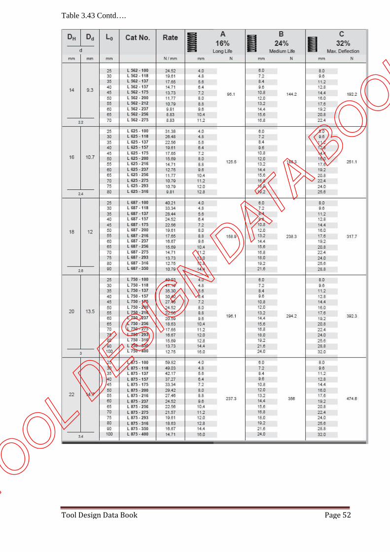
Table 3.43- Circular spring
TOOL DESIG
N DATA B
OOK
Tool Design Data Book Page 52
Table 3.43 Contd….
TOOL DESIG
N DATA B
OOK

Tool Design Data Book Page 53
Table 3.43 Contd…
TOOL DESIG
N DATA B
OOK

Tool Design Data Book Page 54
Table 3.44 – Spring retainer
TOOL DESIG
N DATA B
OOK

Tool Design Data Book Page 55
Table 3.45 - RUBBER SPRINGS
TOOL DESIG
N DATA B
OOK

Tool Design Data Book Page 56
Table 3.46 - RUBBER SPRINGS
TOOL DESIG
N DATA B
OOK

Tool Design Data Book Page 57
Table 3.47 - RUBBER SPRINGS
TOOL DESIG
N DATA B
OOK

Tool Design Data Book Page 58
Table 3.48 - RUBBER SPRINGS
TOOL DESIG
N DATA B
OOK

Tool Design Data Book Page 59
Table 3.49 - RUBBER SPRINGS
TOOL DESIG
N DATA B
OOK

Tool Design Data Book Page 60
Table 3.50 RUBBER SPRINGS
D d d1 t d2
10 18 23 6 1.6
13 23 26 6
16 28 31 6
20 33 36 7
25 40 43 7 3.0
32 50 55 7
38 60 65 8
40 60 65 8
D L
Stripping Pressure (N) at Deflection of
3mm 6mm 9mm
10
44 978 1401 -
54 734 1290 1512
64 703 1060 1268
74 670 1020 1220
13
44 1566 2647 -
54 1357 2180 2469
64 1081 1780 2158
74 811 1707 2139
16
44 2433 3513 -
54 1779 2958 3692
64 1526 2736 3202
74 1490 2650 3182
20
44 3002 4359 -
54 2580 3936 4581
64 2046 3424 4226
74 1939 3180 3980
25
44 4737 6605 -
54 3425 5515 6672
64 3291 5070 6205
74 3158 4781 5887
32
44 6383 9185 -
54 5693 8674 10008
64 4480 6961 8118
74 3469 6491 7570
40
44 8562 12521 -
54 6583 10497 12744
64 5804 9563 11453
TOOL DESIG
N DATA B
OOK

Tool Design Data Book Page 61
BENDING TOOL DESIGN DATA
Bending Allowance(L):
L = (π / 180) x A x (R + 0.5T) When R ≥ 2T
L = (π / 180) x A x (R + 0.33T) When R < 2T
Where A = angle of bend in degrees
R = bend inside radius
T = sheet thickness
Developed Length = Straight arm + Bend allowance
On bends, the short length should be minimum of 2.5 x stock thickness+ radius
TOOL DESIG
N DATA B
OOK

Tool Design Data Book Page 62
Minimum hole (and short slot) to bend distance should be 2.5 x the stock thickness + Bend
radius.
For long slots, the distance should be 4 x the stock thickness + bend radius.
TOOL DESIG
N DATA B
OOK

Tool Design Data Book Page 63
‘V’ Bending:
Bending Force = (1.33LST2) / W
L = length of the bent part in mm
T = thickness of blank in mm
S= Tensile strength of blank material in N/mm2
W = width of ‘V’ at top
‘W’ should not be less than 6 times blank thickness; preferred range is 8 to 10
Edge radius RE = (2 to 6)t
Where, = thickness of material
Punch Radius RP = Radius of component
Die Radius, RD = Punch radius + thickness of material
TOOL DESIG
N DATA B
OOK

Tool Design Data Book Page 64
‘U’ Bending or channel bending:
Bending Force, F = [(0.67LST2) / W]
Span, W = RE + C +RP
Edge Radius, RE = (2 to 6)t for non moving edge
Punch Radius, RP = Part radius
Die radius, RD = RP+ (1.2 to 1.25) t s
C = Die clearance
T =Thickness of blank in ‘mm’
L =Length of bent part.
S = ultimate tensile strength in N/mm2
TOOL DESIG
N DATA B
OOK

Tool Design Data Book Page 65
WIPING DIES:
Bending Force, F = [(0.333LST2)/W]
Span, W = RD + C + RP
Die radius, RD = Part radius
C = Die Radius, RP = 3 to 8T
SPRING BACK:
For low carbon and for soft non ferrous material – 0 to 2°
For 0.40 to 0.5 carbon steel and half hard material – 3 to 5°
Spring back may be high in hardened material – 10 to 15°
Bend radius Tensile strength
400N/mm2 600N/mm2
R = T 4° 7°
R = 5T 6° 12°
Table 4.1 – Spring back data
TOOL DESIG
N DATA B
OOK

Tool Design Data Book Page 66
DRAWING DIES
Type of operation:
h / d ≤ 0.5 – shallow drawing
h / d > 0.5 – deep drawing
Where,
h = shell height
d = shell diameter
Estimation of blank Diameter (Theoretical):
D = √ (d2 + 4dh) when d / r 20 or more
D = √ (d2+4dh – 0.5r) when d / r is between15&20
D = √ (d2+4dh – r) when d / r is between10&15
D = √[(d – 2r)2+4d(h- r) + 2πr(d – 0.7r)] when d / r is below 10
Where,
D – Blank diameter in mm
d – Shell outer diameter in mm
h – Shell Height in mm
r – Corner radius of punch
Considering Trim allowance:
Trim allowance = 0.05mm for every 10 mm diameter. Of drawn cup
Where,
Initial diameter of blank (D1) = D (Theoretical diameter.) + Trim allowance
TOOL DESIG
N DATA B
OOK
Tool Design Data Book Page 67
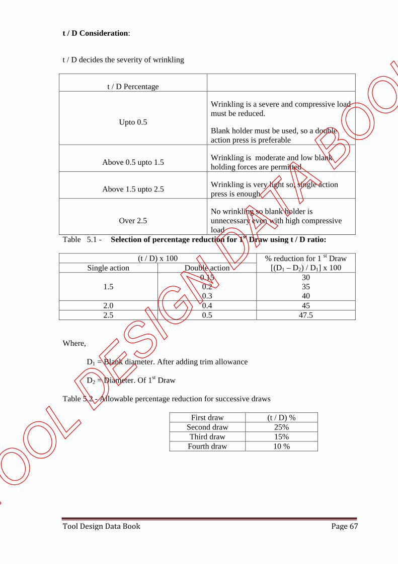
t / D Consideration:
t / D decides the severity of wrinkling
t / D Percentage
Upto 0.5
Wrinkling is a severe and compressive loadmust be reduced.
Blank holder must be used, so a doubleaction press is preferable
Above 0.5 upto 1.5Wrinkling is moderate and low blankholding forces are permitted
Above 1.5 upto 2.5Wrinkling is very light so, single actionpress is enough
Over 2.5No wrinkling so blank holder isunnecessary even with high compressiveload
Table 5.1 - Selection of percentage reduction for 1st Draw using t / D ratio:
(t / D) x 100 % reduction for 1 st Draw[(D1 – D2) / D1] x 100Single action Double action
1.50.150.20.3
303540
2.0 0.4 452.5 0.5 47.5
Where,
D1 = Blank diameter. After adding trim allowance
D2 = Diameter. Of 1st Draw
Table 5.2 - Allowable percentage reduction for successive draws
First draw (t / D) %Second draw 25%Third draw 15%Fourth draw 10 %
TOOL DESIG
N DATA B
OOK

Tool Design Data Book Page 68
Table 5.3 - No. Of Draws according to h / d ratio
h / d ratio No. ofDraws
First draw Seconddraw
Third draw Fourthdraw
Up to 0.75 1 40 -- -- --0.75 – 1.5 2 40 25 -- --
1.5 - 3 3 40 25 15 --3 – 4.5 4 40 25 15 10
Percentage of reduction P= 100(1-d/D)
Where
d= ID of drawn shell
D= OD of blank
Estimation of drawing pressure:
Drawing pressure, p = π x d x t x S x ((D / d)– C)
Where,
P = Drawing force in ‘kgf’
d = Shell outer diameter
D = Blank diameter
t = thickness of sheet in ‘mm’
S = Ultimate tensile strength in N/mm2
C = constant to cover friction and bending (0.6 to 0.7 for ductile material)
Blank holding pressure:
Blank holding pressure = 1/3rd of drawing pressure
Press capacity:
Press capacity = (Drawing pressure + Blank holding pressure) x 1.3
TOOL DESIG
N DATA B
OOK
Tool Design Data Book Page 69
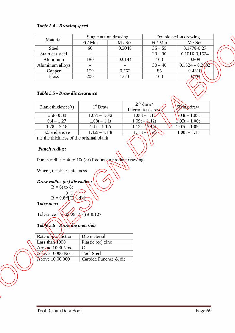
Table 5.4 - Drawing speed
MaterialSingle action drawing Double action drawing
Ft / Min M / Sec Ft / Min M / SecSteel 60 0.3048 35 – 55 0.1778-0.27
Stainless steel - - 20 – 30 0.1016-0.1524Aluminum 180 0.9144 100 0.508
Aluminum alloys - - 30 – 40 0.1524 – 0.2032Copper 150 0.762 85 0.4318Brass 200 1.016 100 0.508
Table 5.5 - Draw die clearance
Blank thickness(t) 1st Draw2nd draw/
Intermittent drawSizing draw
Upto 0.38 1.07t – 1.09t 1.08t – 1.1t 1.04t – 1.05t0.4 – 1.27 1.08t – 1.1t 1.09t – 1.12t 1.05t – 1.06t1.28 – 3.18 1.1t – 1.12t 1.12t – 1.14t 1.07t – 1.09t
3.5 and above 1.12t – 1.14t 1.15t – 1.2t 1.08t – 1.1tt is the thickness of the original blank
Punch radius:
Punch radius = 4t to 10t (or) Radius on product drawing
Where, t = sheet thickness
Draw radius (or) die radius:R = 6t to 8t
(or)R = 0.8√[(D - d)t]
Tolerance:
Tolerance = ± 0.005” (or) ± 0.127
Table 5.6 - Draw die material:
Rate of production Die materialLess than 1000 Plastic (or) zincAround 1000 Nos. C.IAbove 10000 Nos. Tool SteelAbove 10,00,000 Carbide Punches & die
TOOL DESIG
N DATA B
OOK

Tool Design Data Book Page 70
6. DATA FOR GAUGE DESIGN:-
TOOL DESIG
N DATA B
OOK

Tool Design Data Book Page 71
TOOL DESIG
N DATA B
OOK

Tool Design Data Book Page 72
TOOL DESIG
N DATA B
OOK

Tool Design Data Book Page 73
TOOL DESIG
N DATA B
OOK

Tool Design Data Book Page 74
TOOL DESIG
N DATA B
OOK

Tool Design Data Book Page 75
TOOL DESIG
N DATA B
OOK

Tool Design Data Book Page 76
TOOL DESIG
N DATA B
OOK

Tool Design Data Book Page 77
TOOL DESIG
N DATA B
OOK

Tool Design Data Book Page 78
TOOL DESIG
N DATA B
OOK

Tool Design Data Book Page 79
TOOL DESIG
N DATA B
OOK

Tool Design Data Book Page 80
TOOL DESIG
N DATA B
OOK

Tool Design Data Book Page 81
TOOL DESIG
N DATA B
OOK

Tool Design Data Book Page 82
TOOL DESIG
N DATA B
OOK
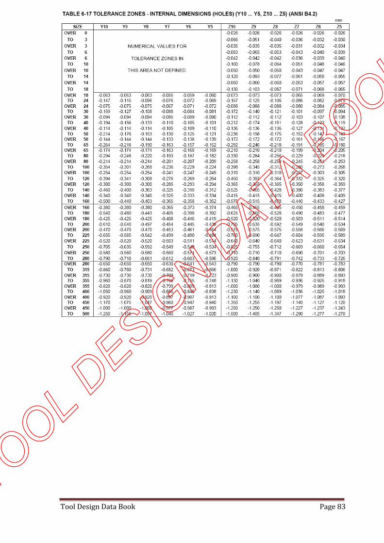
Tool Design Data Book Page 83
TOOL DESIG
N DATA B
OOK

Tool Design Data Book Page 84
TOOL DESIG
N DATA B
OOK

Tool Design Data Book Page 85
TOOL DESIG
N DATA B
OOK

Tool Design Data Book Page 86
TOOL DESIG
N DATA B
OOK

Tool Design Data Book Page 87
TOOL DESIG
N DATA B
OOK

Tool Design Data Book Page 88
TOOL DESIG
N DATA B
OOK

Tool Design Data Book Page 89
TOOL DESIG
N DATA B
OOK

Tool Design Data Book Page 90
TOOL DESIG
N DATA B
OOK

Tool Design Data Book Page 91
TOOL DESIG
N DATA B
OOK

Tool Design Data Book Page 92
TOOL DESIG
N DATA B
OOK

Tool Design Data Book Page 93
TOOL DESIG
N DATA B
OOK

Tool Design Data Book Page 94
TOOL DESIG
N DATA B
OOK

Tool Design Data Book Page 95
TOOL DESIG
N DATA B
OOK

Tool Design Data Book Page 96
TOOL DESIG
N DATA B
OOK

Tool Design Data Book Page 97
TOOL DESIG
N DATA B
OOK

Tool Design Data Book Page 98
TOOL DESIG
N DATA B
OOK

Tool Design Data Book Page 99
TOOL DESIG
N DATA B
OOK

Tool Design Data Book Page 100
TOOL DESIG
N DATA B
OOK

Tool Design Data Book Page 101
TOOL DESIG
N DATA B
OOK

Tool Design Data Book Page 102
Table 6.34 - REFERENCE INDIAN STANDARDS FOR GAUGE DESIGN:-
IS NO. INDIAN STANDARD SPECIFICATION FOR
IS: 3455 – 1971 Gauging practice for Plain work pieces
IS: 6137 – 1983Gauging members for Plain plug gauges, GO and NO GO members
(Size range from 1 upto and including 40mm)
IS: 6244- 1980Gauging members for Plain plug gauges, GO and NO GO members
(Size range above 40 to 120 mm)
IS: 6246 – 1980Gauging members for Plain plug gauges, GO and NO GO members
(Size range above 120 up to and including 250 mm)
IS: 7018 (Part 1)
– 1983Technical supply conditions for gauges – Part 1 General
IS: 7018 (Part 2)
– 1983
Technical supply conditions for gauges – Part 2 - Assembly and
inspection Plain Plug gauges ( Size range from 1 mm upto and
including 250 mm)
IS: 7018 (Part 3)
– 1983
Technical supply conditions for gauges – Part 3- Assembly and
identification of screw plug gauges for ISO metric screw threads (
Size range from M1 upto and including M200)
IS: 5388 – 1983 Hexagon handles for Plain and Threaded Plug gauges
IS: 3477 – 1973 GO and NO GO Snap Gauges for size range 3 to 250 mm
IS: 3485 - 1966 Plain ring gauges
Note:- Use of Institute copies of all the above Indian Standards and any other related
Indian standards is permitted in the Tool Design and Drawing examination for the D.M.E (
Tool & Die) course.
TOOL DESIG
N DATA B
OOK

Tool Design Data Book Page 103
JIGS & FIXTURES
Table 7.1 - GUIDELINES FOR SELECTION OF LOCATORS
SI.NO LOCATING DEVICE APPLICATION1 Six point locator(3-2-1) pin and button
locatorsLocating flat surfaces
2 V-block Locating round circularflat
3 Nesting locator Locating cylindricalprofile in verticalposition.
4 V-block, horizontal (one side is fixed andother end is adjustable or cam operated)V-locator.
Locating elliptical andirregular surfaces.
5 Jack pin locator Locating a rough workpiece.
6 Eccentric locators Variation in work piecesize.
Table 7.2 - GUIDELINES FOR SELECTION OF CLAMPSCLAMPS SITUATIONS
Strap clamp Commonly used for rectangular workpieces.
Swinging strap clamp For easy loading and un loading.
Cam operated clamp Effective and fast, but should be used.
Toggle clamp Adapted for many types of fixtures.
Screw clamp Components are to grip on.
Equalizing clamp Exerting equal pressure to hold.
Hydraulic and pneumatic clamp Faster, uniform and effective.
Hydraulic clamp with rack and pinion Circular rod in V-block
Spider clamp Circular and symmetrical workpiececlamping.
Edge clamp Used during facing operation.
TOOL DESIG
N DATA B
OOK

Tool Design Data Book Page 104
Table 7.3 - LOCATING PINS (ROUND) - IS 5093
D g6 dd1
p6 d2 h1 h2
10 9.5 8 7.5 8 1612 11.5 10 9.5 10 1816 15 12 11.5 14 2220 19 16 15.5 18 2525 24 20 19.5 22 32
32 31 25 24.5 25 36
Table 7.4 - END LOCTING PLUGS - IS 5095Dh6
dd1
p6d2 h1 h2
16 15 12 11.5 12162540
20 19 16 15.5 15203245
25 24 20 19.5 18254060
32 31 25 24.5 2240
63
40 39 32 31.5 2550
80
TOOL DESIG
N DATA B
OOK

Tool Design Data Book Page 105
Table 7.5 - DIAMOND LOCATING PINS - IS 5094De8
dd1
p6d2 b h1 h2
12 11 8 7.5 4 8 12
14 13 10 9.5 5 10 14
18 17 12 11.5 6 14 18
22 21 16 15.5 8 18 21
28 27 20 19.5 10 22 28
36 35 25 24.5 12 25 32
Table 7.6 - ROUND LOCATING STUDS - IS 5096
Dg6
dd1
p6d2 d3
d4
s7h h1 h2
12
11.5
10
9.5 M6 540
10
12
18
1714
13.5
M8 655
16
18
20
1916
15.5
M10
862
18
20
25
2420
19.5
M12
10
70
22
25
32
3125
24.5
M16
12
85
25
28
Table 7.7 - V-LocatorL1 l2 l3 b1 b2 b3 dTOOL D
ESIGN D
ATA BOOK

Tool Design Data Book Page 106
25 20 35 15 32 15 7
36 25 50 20 45 25 9
50 32 60 22 55 30 11Table 7.8 - V-Block
a b c dmax dmin
50 40 40 40 5
63 50 50 50 5
80 63 63 63 7
100 80 80 83 7
200 200 200 200 10
300 300 300 300 12
Table 7.8 - SWING CLAMP - IS 5250
d w W1 t L L1 L2 L3 a rSizeof
screw
6.6 20 7 12 52 20 25 14 4 12 M6
9 25 9 14 60 22 30 18 5 14 M8
11 30 11 16 70 24 35 20 6 16 M10
14 35 15 20 80 26 40 22 7 20 M12
18 45 18 25 90 32 45 28 9 25 M16
22 50 23 30 100 38 50 32 11 30 M20
Table 7.9 - STRAP CLAMP – IS 4292
d l1 a b c h sFor
screwsize
7 50 10 20 8 10 20 M610 60 13 22 10 12 25 M812 80 15 30 12 15 30 M1015 100(125) 21 40(50) 14 20 40 M1219 125(160) 26 45(65) 18 25 50 M1624 160(200) 30 60(80) 22 30 60 M20TOOL D
ESIGN D
ATA BOOK

Tool Design Data Book Page 107
28 200(250) 35 80(105) 26 30(40) 70 M2435 250(315) 45 100(130) 34 40(50) 80 M3042 315(350) 48 125(150) 40 45(55) 90 M3645 350(400) 53 150(180) 45 55(60) 100 M39
Table 7.10 - SWING ‘C’ WASHER- IS 4298
dH13
d1 R R1 R2 R3 R4 rt
Nom
Forboltor
screwsize
6.6 8.5 18 8 21.3 14.7 10.0 2.0 6 M69.0 8.5 21 8 25.5 16.5 13.0 2.5 6 M811 8.5 24 8 29.5 18.5 16.0 2.5 6 M1014 10.5 27 10 34.0 20.0 20.0 3.0 8 M1218 10.5 33 10 42.0 24.0 25.0 3.0 8 M1622 10.5 38 10 49.0 27.0 30.0 3.0 8 M20
26 12.5 42 12 55.0 29.0 32.5 4.0 10 M24
30 12.5 45 12 60.0 30.0 35.0 4.0 10 M27
TOOL DESIG
N DATA B
OOK

Tool Design Data Book Page 108
Table 7.11 - JIG BUTTON (IS 4294)MATERIAL: C45 HARDNESS: 45 – 50RC
d1 d2 h a l Under cut6 4 5 1.2 6 A2 X 0.210 6 8 1.6 8 B2 X 0.216 8 5/13 2.0 10 B2 X 0.225 12 8/20 2.5 14 B2 X 0.2
40 20 13/32 3.2 20 B2 X 0.2
Table 7.12 - JIG FEETMATERIAL: FREE CUTTING STEEL – HARDNESS:56 ± 2RC
H d b d1 d2 e1 K l r1 r2 S X ∞
1020
M6 11 6 8 12.7 52131
0.5 1 11 2.034º13º
1530
M8 13 9 10 16.2 62843
0.5 1 14 2.522º9º
2040
M10
16 12 12 19.6 83656
0.5 1.5 17 2.518º7º
2550
M12
20 15 15 25.4 104570
0.5 1.5 22 3.020º8º
3060
M16
24 20 19 31.2 125484
1.0 2 27 3.018º7º
4080
M20
29 26 24 36.9 1669
1091.0 2 32 4.0
13º5º
TOOL DESIG
N DATA B
OOK

Tool Design Data Book Page 109
Table 7.13 - FEET BOLTBasicsize
A B C D E ø F ø
M10 50 28 12 12-20 10 20
M10 65 28 12 12-20 10 20
M10 75 28 12 12-20 10 20
M10 90 28 12 12-20 10 20
M12 75 35 18 20-25 12 25
M12 90 35 18 20-25 12 25
M12 100 35 18 20-25 12 25
M12 112 35 18 20-25 12 25
M12 125 35 18 20-25 12 25
M12 140 35 18 20-25 12 25
M12 150 35 18 20-25 12 25
Table 7.14 - FEET NUTS
Basicsize
M10 M10 M10 M10 M12 M12 M12 M12 M12 M12 M12
A 20 25 36 50 20 25 36 50 62 75 87
B ø 20 20 20 20 25 25 25 25 25 25 25
TOOL DESIG
N DATA B
OOK

Tool Design Data Book Page 110
Table 7.15 - JIG BUSHFIXED BUSH
d1Short
l1 l2
Longl1 l2
d2 d3 d4 r1 r2 Z
Upto 1 6 4 9 7 3 6 - 1.2 0.2 0.0051.0-1.8 6 4 9 7 4 7 - 1.2 0.2 0.0051.8-2.6 6 4 9 7 5 8 - 1.2 0.3 0.0052.6-3.3 8 6 12 9 6 10 - 1.6 0.3 0.0053.3-4.0 8 6 12 9 7 11 - 1.6 0.4 0.0054.0-5.0 8 6 12 9 8 12 - 2.0 0.4 0.0055.0-6.0 10 7 16 13 10 14 - 2.0 0.4 0.016.0-8.0 10 7 16 13 12 16 10 2.0 0.6 0.018.0-10 12 8 20 16 16 20 13 2.5 0.8 0.0110-12 12 8 20 16 18 22 16 2.5 0.8 0.0112-15 16 12 28 24 25 26 20 4.0 0.8 0.0115-18 16 12 28 24 25 30 24 4.0 0.8 0.0118-22 20 15 36 31 30 35 28 6.0 1.0 0.0122-26 20 15 36 31 36 41 33 6.0 1.0 0.0226-30 20 15 36 31 42 47 40 6.0 1.0 0.0230-35 25 20 45 40 48 55 46 8.0 1.0 0.0235-42 25 20 45 40 56 63 52 8.0 1.0 0.0242-48 32 25 56 50 63 70 59 8.0 1.6 0.0248-55 32 25 56 50 70 77 67 8.0 1.6 0.0255-63 36 30 72 66 80 87 75 8.0 1.6 0.02
TOOL DESIG
N DATA B
OOK

Tool Design Data Book Page 111
Table 7.16 - LINER BUSH
d1Short Long d2 r1 r2 z
Upto 1 6 9 3 1.2 0.2 0.0051.0-1.8 6 9 4 1.2 0.2 0.0051.8-2.6 6 9 5 1.2 0.3 0.0052.6-3.3 8 12 6 1.6 0.3 0.0053.3-4.0 8 12 7 1.6 0.4 0.0054.0-5.0 8 12 8 2.0 0.4 0.0055.0-6.0 10 16 10 2.0 0.4 0.016.0-8.0 10 16 12 2.0 0.6 0.018.0-10 12 20 16 2.5 0.8 0.0110-12 12 20 18 2.5 0.8 0.0112-15 16 28 22 4.0 0.8 0.0115-18 16 28 25 4.0 0.8 0.0118-22 20 36 30 6.0 0.8 0.0122-26 20 36 36 6.0 1.0 0.0226-30 20 36 42 6.0 1.0 0.0230-35 25 45 48 8.0 1.0 0.0235-42 25 45 56 8.0 1.0 0.0242-48 30 56 63 8.0 1.6 0.0248-55 30 56 70 8.0 1.6 0.0255-63 36 70 80 8.0 1.6 0.02
TOOL DESIG
N DATA B
OOK

Tool Design Data Book Page 112
Table 7.17 - SLIP BUSH
d1 d2 d3 d4 d5 l1 l2 l3 a b r1 z X
Upto 4 8 16 11 2.5 20 10 1 3 4 3 0.01 14
4-6 10 19 14 2.5 22 12 1 3 4 3 0.01 12
6-8 12 22 17 2.5 25 12 1 3 4 4 0.01 10
8-10 16 26 21 3.0 28 16 1 4 5 5 0.01 12
10-12 18 30 24 3.0 28 16 1 4 5 5 0.01 10
12-15 22 35 29 5.0 36 20 1 5 7 5 0.01 1215-18 25 40 35 5.0 36 20 1 5 7 5 0.01 8
18-22 30 47 41 5.0 36 20 1 5 7 6 0.01 0
22-26 36 56 47 6.0 45 25 2 6 8 6 0.02 0
26-30 42 62 54 6.0 45 25 2 6 8 6 0.02 0
30-35 48 69 61 6.0 50 32 2 6 11 8 0.02 0
35-42 56 78 69 6.0 50 32 2 6 11 8 0.02 0
42-48 63 85 78 6.0 56 36 2 6 14 8 0.02 0
TOOL DESIG
N DATA B
OOK

Tool Design Data Book Page 113
Table 7.18 - LOCKING SCREWS
d6 d7 d8 l4 l5 l6 h d6 m6Ø * l m n t r2 cM5M5M5M5M5
10 5 6 6 15 2
2.5 X 142.5 X 142.5 X 143.0 X 143.0 X 14
1012121616
1.6 2.0 0.6
1516182022
M6M6M6
13 6 8 8 20 25 X 205 X 205 X 20
202020
2.0 2.5 1.0262933
M8M8M8M8M8
16 8 10 10 25 2.5
6 X 246 X 246 X 246 X 246 X 28
2525303035
2.5 3.0 1.6
3841454855
TOMMY NUT (Material –C 45)Basic size AØ BØ
M10 25 28
M12 25 35
M16 32 38
TOOL DESIG
N DATA B
OOK

Tool Design Data Book Page 114
Table 7.19 - KNURLED THUMB NUT (Material –C 45)Basic size AØ BØ C D
M6 20 16 10 1.5
M8 22 20 12 1.5
M10 2522
12 3
M12 2825
14 3
M16 3528
16 3
Table 7.20 - THUMB NUT (Material –C 45)d1 d2 b h e
M6 7 28 12 12M8 9 32 14 14M10 11 36 16 16M12 13 45 18 18
M16 18 54 22 22
Table 7.21 – Hand nut
HAND NUT (Material –C 45)
AØ BØ CØ DØ E F G H J K41 32 23 M12 14 8 3 6 3 2554 38 27 M16 17 13 5 8 5 3558 41 30 M20 17 13 5 8 5 3564 45 32 M22 19 17 5 10 6 4170 50 38 M24 21 17 6 10 6 4480 56 45 M30 25 19 8 11 8 52
TOOL DESIG
N DATA B
OOK

Tool Design Data Book Page 115
d a d2 E g h l2
M10 6 3 75 3.5 12 40ll1
4025
4530
5035
5540
6045
6550
M12 7.5 4 90 4.0 15 50ll1
5031
5536
6041
6546
7051
7556
8061
M16 10.0 5 117 4.5 19 63ll1
6540
7045
7550
8560
9570
10580
M20 12.5 6 150 6.5 24 80ll1
8049
8554
9059
10069
11079
12089
13099
Table 7.22 – Handle grip screws
TOOL DESIG
N DATA B
OOK

Tool Design Data Book Page 116
Table 7.23 - WING/ FLY SCREWS
d a d2 eg
approx.h h1
M5 3 1.5 25 1.5 7 12ll1
2516
M6 4 1.5 32 2.0 8 16ll1
2820
3022
3527
M8 5 2.0 40 2.5 9.5 20ll1
3525
4030
4535
M10 6 3.0 50 3.5 12.0 25ll1
5038
5543
6048
6553
TOOL DESIG
N DATA B
OOK

Tool Design Data Book Page 117
Table 7.24 - PRESSURE PADS
Max.dia.d1
d4 d5 d6 d7 e f h r1 r2 t2 t1For screw
with threadFastening
pin
10 3.8 8 4 1.5 2.5 2.5 7 1.2 0.3 0.5 4.5 M5 1.5m6 x 612 4.8 10 5 1.5 2.5 2.5 8 1.5 0.3 0.5 5 M6 1.5m6 x 816 6.4 12 7 2 3 3.5 9.5 2 0.4 0.5 6 M8 2m6 x 820 7.4 15 8 2 3.5 5 12 2 0.4 1 7 M10 2m6 x 1425 9.5 18 10 3 4.5 6 15 3 0.6 1 9 M12 3m6 x 1432 12.5 22 14 3 6 7 19 3 0.6 1 12 M16 3m6 x 1640 15.5 28 18 4 7.5 9 24 4 0.8 1 15 M20 4m6 x 20
Table 7.25 - Cam clamp (Material – Mild steel)A B C D E F G10 13 1.5 3 12 60 1012 16 2 4 15 70 1216 20 2.5 5 18 90 16
20 25 3 6 24
110 20
TOOL DESIG
N DATA B
OOK
Tool Design Data Book Page 118
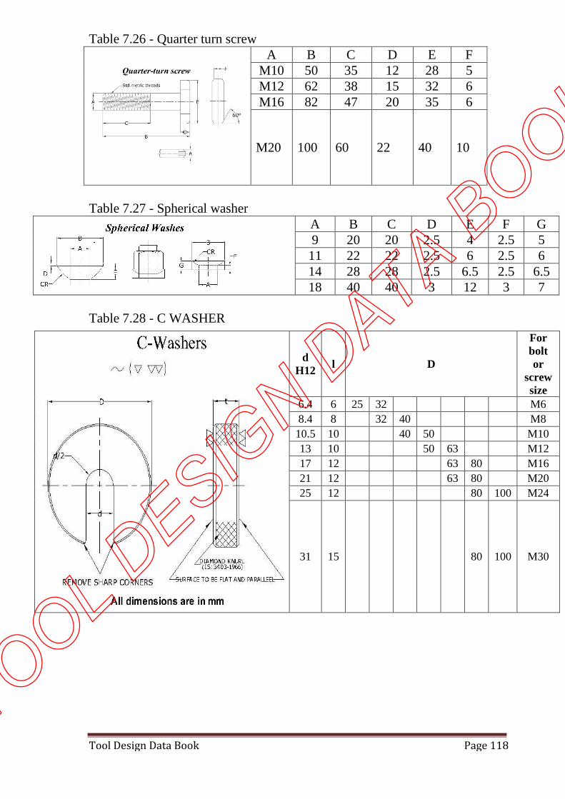
Table 7.26 - Quarter turn screwA B C D E F
M10 50 35 12 28 5M12 62 38 15 32 6M16 82 47 20 35 6
M20 100 60 22 40 10
Table 7.27 - Spherical washerA B C D E F G9 20 20 2.5 4 2.5 5
11 22 22 2.5 6 2.5 614 28 28 2.5 6.5 2.5 6.518 40 40 3 12 3 7
Table 7.28 - C WASHER
dH12
l D
Forboltor
screwsize
6.4 6 25 32 M6
8.4 8 32 40 M8
10.5 10 40 50 M10
13 10 50 63 M12
17 12 63 80 M16
21 12 63 80 M20
25 12 80 100 M24
31 15 80 100 M30
TOOL DESIG
N DATA B
OOK
Tool Design Data Book Page 119
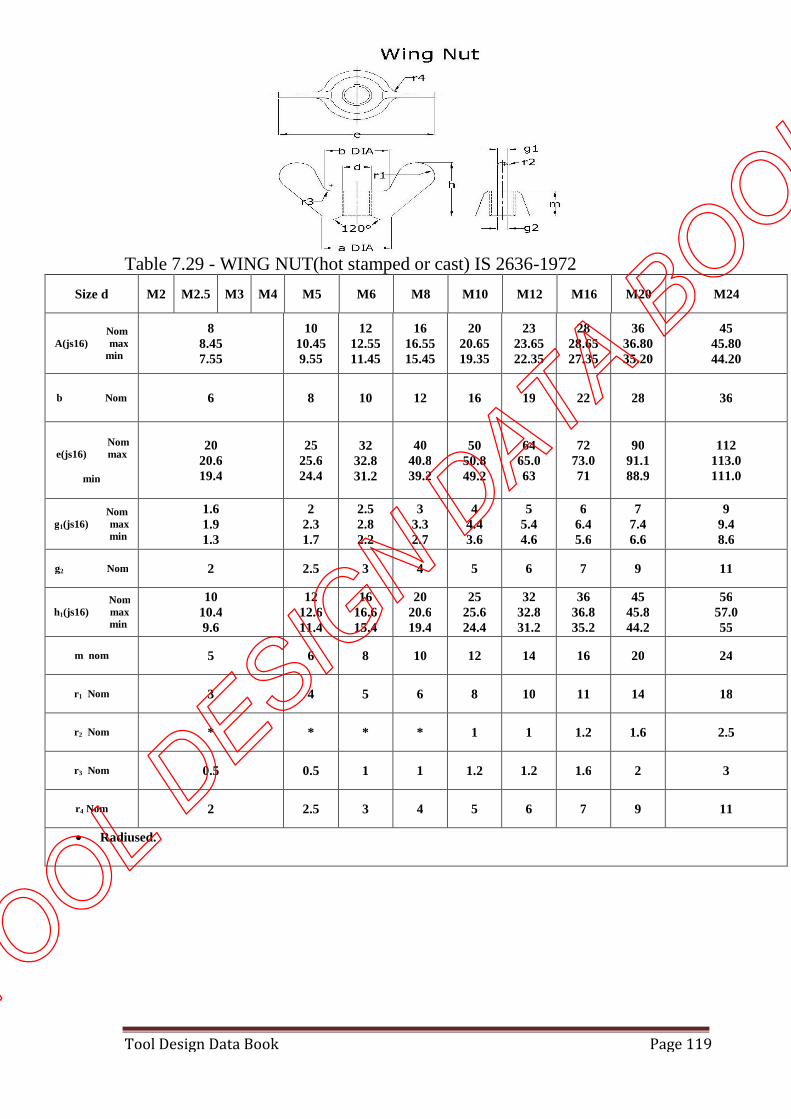
Table 7.29 - WING NUT(hot stamped or cast) IS 2636-1972
Size d M2 M2.5 M3 M4 M5 M6 M8 M10 M12 M16 M20 M24
NomA(js16) max
min
88.457.55
1010.459.55
1212.5511.45
1616.5515.45
2020.6519.35
2323.6522.35
2828.6527.35
3636.8035.20
4545.8044.20
b Nom 6 8 10 12 16 19 22 28 36
Nome(js16) max
min
2020.619.4
2525.624.4
3232.831.2
4040.839.2
5050.849.2
6465.063
7273.071
9091.188.9
112113.0111.0
Nomg1(js16) max
min
1.61.91.3
22.31.7
2.52.82.2
33.32.7
44.43.6
55.44.6
66.45.6
77.46.6
99.48.6
g2 Nom 2 2.5 3 4 5 6 7 9 11
Nomh1(js16) max
min
1010.49.6
1212.611.4
1616.615.4
2020.619.4
2525.624.4
3232.831.2
3636.835.2
4545.844.2
5657.055
m nom 5 6 8 10 12 14 16 20 24
r1 Nom 3 4 5 6 8 10 11 14 18
r2 Nom * * * * 1 1 1.2 1.6 2.5
r3 Nom 0.5 0.5 1 1 1.2 1.2 1.6 2 3
r4 Nom 2 2.5 3 4 5 6 7 9 11
Radiused.
TOOL DESIG
N DATA B
OOK

Tool Design Data Book Page 120
Table 8 - Unit conversionsConversions factors
SIPHYSICALQUANTITY
MKS FPS
1 N Force 0.1016 kgf 0.2248 Ibf
1 N/m2 Pressure 10.19 x 10⁻⁶ kgf/cm2 145.038x10⁻⁶ kgf/cm2
1kW Power 1kW, 1.36hp 1.34hp
1 Nm/s Power 0.1019 kgfm/s 0.7375 ft lpf/s
Metric conversion table
Multiply ByTo get equivalent number
to
InchFootYardMile
Length25.4
0.30480.91441.609
Millimeters (mm)Meters (m)Meters (m)
Kilometers(km)
Inch2
Foot2
Yard2
Area645.26.45
0.09290.8361
Millimeters2(mm2)Centimeters2(cm2)
Meters2 (m2)Meters2
Inch3
Yard3
Volume16.38716.387
mm3
cm3
PoundTon
Mass0.4536907.18
Kilograms (kg)Kilograms (kg)
KilogramOunce
Force9.8070.278
Newton (N)Newton(N)
Foot/Second2
Inch/Second2
Acceleration0.30480.0254
Meter per second2(m/s2)Meter per second2
Horse powerPower0.746 Kilowatts(kW)
TOOL DESIG
N DATA B
OOK


![A Computational Design Tool for Compliant … Computational Design Tool for Compliant Mechanisms ... [Coros et al. 2013], ... A Computational Design Tool for Compliant Mechanisms •](https://img.pdfslide.net/doc/110x75/5a90e3117f8b9a4a268e64ed/pdfa-computational-design-tool-for-compliant-computational-design-tool-for.jpg)