Embed Size (px)
Citation preview
INTERNATIONAL STANDARD
ISO 86884
First edition 1989-05-01
Tool life testing in milling -
Part 1 : Face milling
Essai de durbe de vie des outils de fraisage -
Partie I : Surfaqage
Reference number ISO 8688-1 : 1989 (EI
Voorbeeld
Preview
Dit document is een voorbeeld van NEN / This document is a preview by NEN
Dit
do
cum
ent
mag
sle
chts
op
een
sta
nd
-alo
ne
PC
wo
rden
gei
nst
alle
erd
. Geb
ruik
op
een
net
wer
k is
alle
en.
toes
taan
als
een
aan
vulle
nd
e lic
enti
eove
reen
kom
st v
oo
r n
etw
erkg
ebru
ik m
et N
EN
is a
fges
lote
n.
Th
is d
ocu
men
t m
ay o
nly
be
use
d o
n a
sta
nd
-alo
ne
PC
. Use
in a
net
wo
rk is
on
ly p
erm
itte
d w
hen
a su
pp
lem
enta
ry li
cen
se a
gre
emen
t fo
r u
s in
a n
etw
ork
wit
h N
EN
has
bee
n c
on
clu
ded
.

ISO 8688-1 :1989(E)
Foreword
ISO (the International Organization for Standardization) is a worldwide federation of national Standards bodies (ISO member bodies). The work of preparing International Standards is normally carried out through ISO technical committees. Esch member body interested in a subject for which a technical committee has been established has the right to be represented on that committee. International organizations, govern- mental and non-governmental, in liaison with ISO, also take part in the work. ISO collaborates closely with the International Electrotechnical Commission (IEC) on all matters of electrotechnical standardization.
Draft International Standards adopted by the technical committees are circulated to the member bodies for approval before their acceptance as International Standards by the ISO Council. They are approved in accordance with ISO procedures requiring at least 75 % approval by the member bodies voting.
International Standard ISO 8668-1 was prepared by Technical Committee ISO/TC 29, Smalf tools.
Users should note that all International Standards undergo revision from time to time and that any reference made herein to any other International Standard implies its Jatest edition, unless otherwise stated.
0 ISO 1989 All rights reserved. No part of this publication may be reproduced or utilized in any form or by any means, electronie or mechanical, including photocopying and microfilm, without Permission in writing from the publisher.
International Organization for Standardization Case postale 56 l CH-1211 Geneve 20 l Switzerland
P’rinted in Switzerland
ii
Voorbeeld
Preview
Dit document is een voorbeeld van NEN / This document is a preview by NEN
ISO 8688-1 : 1989 (El
Contents Page
0 Introduction ........................................................
1 Scope and field of application .........................................
2 References .........................................................
3 Workpiece.. .......................................................
3.1 Work material. ..................................................
3.2 Dimensions .....................................................
4 Tool:Cutter ........................................................
4.1 Dimensions and tolerantes. .......................................
4.2 Tool geometry ..................................................
4.3 Cutting edge and insert sutface ....................................
4.4 Tool material. ...................................................
4.5 Mounting of the tool .............................................
5 Cutting fluid. .......................................................
6 Cutting conditions ..................................................
6.1 Recommended cutting conditions .................................
6.2 Other cutting conditions ..........................................
6.3 Location of the Cutter ............................................
6.4 Cuttingspeed ...................................................
7 Tool deterioration and tool-life criteria ..................................
7.1 Introduction ....................................................
7.2 Definitions .....................................................
7.3 Tool deterioration phenomena .....................................
7.4 Tool deterioration phenomena used as tool-life criteria ................
1
1
2
2
2
3
3
3
3
3
5
5
5
5
5
6
6
6
6
6
6
7
12
7.5 Assessment of tool deterioration . . . . . . . . . . . . . . . . . . . . . . . . . . . . . . . . . . . 12
. . . Ill
Voorbeeld
Preview
Dit document is een voorbeeld van NEN / This document is a preview by NEN
IsO8688-1 : 1989 EI
8 Equipment ......................................................... 15
8.1 Machinetool.. .................................................. 15
8.2 Other equipement ............................................... 16
9 Procedure .......................................................... 16
9.1 Purpose ........................................................ 16
9.2 Planning ....................................................... 16
9.3 Preparation of material, tools and equipment ........................ 17
9.4 Test techniques ................................................. 17
9.5 Measurements and recording of tool deterioration .................... 18 .
IO Evaluation of results ................................................. 18
10.1 General considerations .......................................... 18
10.2 Treatment of test values ......................................... 18
10.3 Number of test runs ............................................. 18
10.4 Diagrams ...................................................... 20
10.5 Statistical interpretation ......................................... 20
Annexes
A Reference work materials ............................................. 22
B Toolsetting ......................................................... 23
C Exampledatasheet .................................................. 24
D Statistical calculations. ............................................... 25
Bibliography . . . . . . . . . . . . . . . . . . . . . . . . . . . . . . . . . . . . . . . . . . . . . . . . . . . . . . . . . . 27 Voorbeeld
Preview
Dit document is een voorbeeld van NEN / This document is a preview by NEN
INTERNATIONAL STANDARD ISO86884 : 1989 (E)
Tool life testing in milling -
Part 1 : Face milling
0 Introduction
Procedures and conditions for tool-life testing with Single-Point turning tools are the subject of ISO 3685. Successful applica- tion of ISO 3685 resulted in requests for similar documents relating to other commonly used cutting methods.
This part of ISO 8688 has been developed on the initiative of the International Institution for Production Engineering Research (CIRP) and applies to face milling operations with carbide tools, as illustrated in figure 1, which represent a major manufactur- ing activity.
The recommendations contained in this part of ISO 8688 are applicable in both laboratories and factories. They are intended to unify procedures in Order to increase the reliability and com- parability of test results when making comparison of cutting tools, work materials, cutting Parameters or cutting fluids. In Order to achieve as far as possible these aims, recommended reference materials and conditions are included and should be used as far as is practical.
In addition, the recommendations tan be used to assist in establishing recommendable cutting data, or to determine limiting factors and machining characteristics such as cutting forces, machined surface characteristics, chip form, etc. For these purposes in particular, certain Parameters, which have been given recommended values, may have to be used as variables.
The test conditions recommended in this patt of ISO 8688 have been designed for face milling tests using steel and cast iron workpieces of normal microstructure. However, with suitable modifications, this part of ISO 8688 tan be applied to face mill- ing tests on, for example, other work materials or with cutting tools developed for specific applications.
The specified accuracy given in these recommendations should be considered as a minimum requirement, Any deviation from
the recommendations should be reported in detail in the test report.
NOTE - This part of ISO 8688 does not constitute acceptance tests and should not be used as such.
1 Scope and field of application
This part of ISO 8688 specifies recommended procedures for tool-life testing with cemented carbide tools used for face mill- ing of steel and cast iron workpieces. lt tan be applied to laboratory as well as to production practice.
The cutting conditions in face milling may be considered under two categories as follows :
a) conditions as a result of which tool deterioration is due predominantly to wear;
b) conditions under which tool deterioration is due mainly to other phenomena such as edge fracture or plastic defor- mation.
This part of ISO 8688 considers only those recommendations concerned with testing which results predominantly in tool wear.
Testing for the second group of conditions given above is cur- rently under study.
This patt of ISO 8688 establishes specifications for the follow- ing factors of tool-life testing with face milling tools in accord- ante with figure 1: workpiece, tool, cutting fluid, cutting conditions, equipment, assessment of tool deterioration and tool life, test procedures, recording, evaluation and presen- tation of results.
Voorbeeld
Preview
Dit document is een voorbeeld van NEN / This document is a preview by NEN
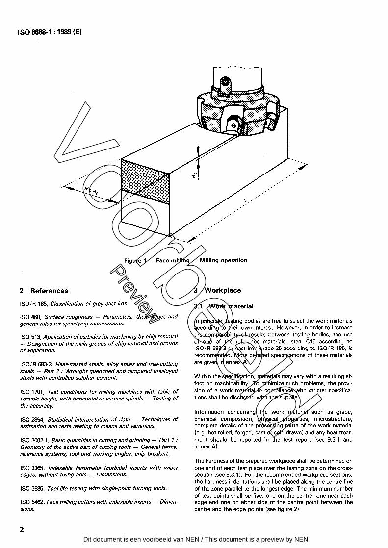
Figure 1 - Face milling - Milling Operation
2 References
ISO/R 185, Classification of grey cast iron.
ISO 468, Surface roughness - Parameters, their values and general rules for specifying requiremen ts.
ISO 513, Application of carbides for machining by Chip removal - Designation of the main groups of Chip removal and groups o f applica tion.
ISOIR 683-3, Heat-treated steels, alloy steels and free-cutting steels - Part 3 : Wrought quenched and tempered unalloyed s teels with con trolled sulphur con ten t.
ISO 1701, Test conditions for milling machines with table of variable height, with horizontal or vertical spindle - Testing of the accuracy.
ISO 2854, S tatistical in terpreta tion of data - Techniques of estimation and tests relating to means and variances.
ISO 3002-1, Basic quantities in cutting and grinding - Part 7 : Geometry of the active part of cutting tools - General terms, reference Systems, tool and working angles, Chip breakers.
ISO 3365, lndexable hardmetal (carbidel inserts with wiper edges, without frxing hole - Dimensions.
ISO 3685, Tool-life testing with Single-poin t turning tools.
ISO 6462, Face milling Cutters with indexable inserts - Dimen- sions.
2
3 Workpiece
3.1 Work material
In principle, testing bodies are free to select the work materials according to their own interest. However, in Order to increase the comparability of results between testing bodies, the use of one of the reference materials, steel C45 according to ISO/R 683-3 or cast iron grade 25 according to ISO/R 185, is recommended. More detailed specifications of these materials are given in annex A.
Within the specification, materials may vary with a resulting af- fett on machinability. To minimize such Problems, the provi- sion of a work material in compliance with stricter specifica- tions shall be discussed with the supplier.
Information concerning the work material such as grade, Chemical composition, physical properties, microstructure, complete details of the processing route of the work material (e.g. hot rolled, forged, cast or cold drawn) and any heat treat- ment should be reported in the test report (sec 9.3.1 and annex AI.
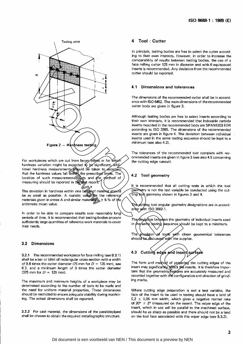
The hardness of the prepared workpiece shall be determined on one end of each test piece over the testing zone on the cross- section (sec 9.3.1). For the recommended workpiece sections, the hardness indentations shall be placed along the centre-line of the zone parallel to the longest edge. The minimum number of test Points shall be five; one on the centre, one near each edge and one on either side of the centre Point between the centre and the edge Points (sec figure 2).
Voorbeeld
Preview
Dit document is een voorbeeld van NEN / This document is a preview by NEN
- Testing zone \
ISO 8688-1 : 1989 (El
4 Tool : Cutter
,
Figure 2 - Hardness testing
For workpieces which are tut from larger billets or for which hardness Variation might be expected to be significant, addi- tional hardness measurements should be taken to ascertain that the hardness values fall within the prescribed limits. The location of such measurement Points and the method of measuring should be reported in the test report.
The deviation in hardness within one batch of material should be as small as possible. A realistic value for the reference materials given in annex A and similar materials is + 5 % of the arithmetic mean value.
In Order to be able to compare results over reasonably long periods of time, it is recommended that testing bodies procure suff iciently large quantities of reference work materials to cover their needs.
3.2 Dimensions
3.2.1 The recommended workpiece for face milling (see 9.3.1) shall be a bar or billet of rectangular Cross-section with a width of 0,6 times the Cutter diameter (75 mm for D = 125 mm), see 6,3, and a minimum length of 3 times the Cutter diameter (375 mm for D = 125 mm).
The maximum and minimum heights of a workpiece may be determined according to the number of tests to be made and the need for uniform material properties. These dimensions should be restricted to ensure adequate stability during machin- ing. The actual dimensions shall be reported.
3.2.2 For cast material, the dimensions of the parallelepiped shall be Chosen to obtain the required metallographic structure.
In principle, testing bodies are free to select the Cutter accord- ing to their own interests. However, in Order to increase the comparability of results between testing bodies, the use of a face milling Cutter 125 mm in diameter and with 6 equispaced inserts is recommended. Any deviation from the recommended Cutter should be reported.
4.1 Dimensions and tolerantes
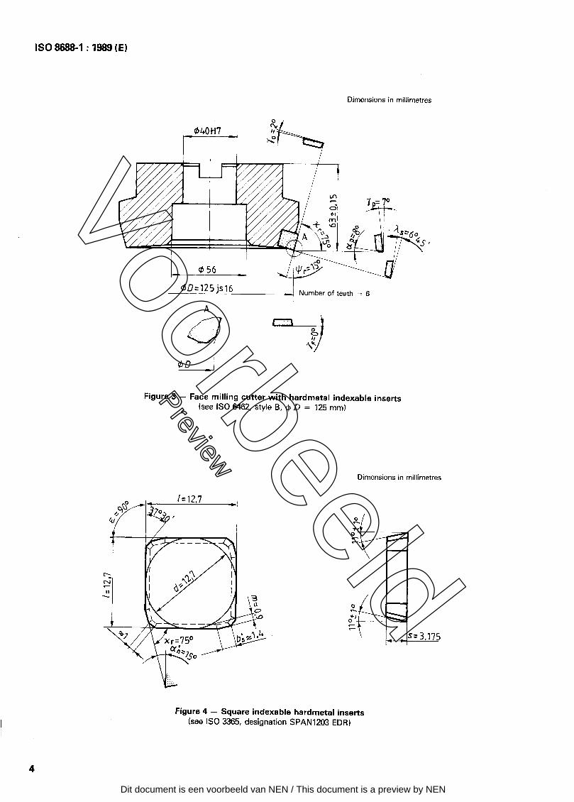
The dimensions of the recommended Cutter shall be in accord- ante with ISO 6462. The main dimensions of the recommended Cutter body are given in figure 3.
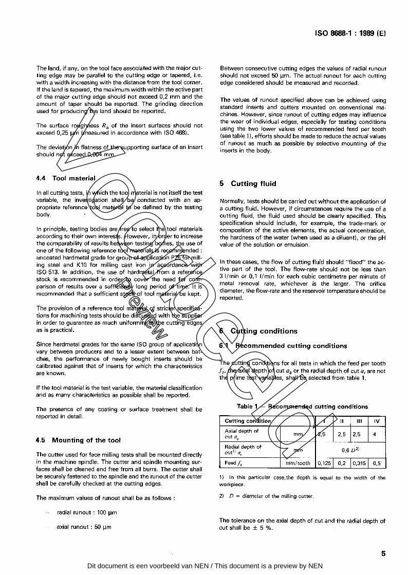
Although testing bodies are free to select inserts according to their own interests, it is recommended that indexable carbide inserts mounted in the recommended body are SPAN1203 EDR according to ISO 3365. The dimensions of the recommended inserts are given in figure 4. The deviation between individual inserts used in the same testing sequence should be kept to a minimum (see also 4.2).
The tolerantes of the recommended tool complete with rec- ommended inserts are given in figure 3 (sec also 4.5 concerning the cutting edge runout).
4.2 Tool geometry
lt is recommended that all cutting tests in which the tool geometry is not the test variable be conducted using the cut- ting tool geometry shown in figures 3 and 4.
The cutting tool angular geometry designations are in accord- ante with ISO 3002-1.
The deviation between the geometry of individual inserts used in the same testing seq uen ce should be kept to a minimum.
The Provision of tools with closer should be discussed with the supplier.
geometrical tolerantes
4.3 Cutting edge and insert surface
The form and method of preparing the cutting edges of the insert may significantly affect the results. lt is therefore impor- tant that the geometric features are accurately measured and recorded together with the configuration and direction of grind- ing marks.
Where cutting edge preparation is not a test variable, the face of the insert to be used in testing should haue a land of 0,2 + 0,05 mm width, which gives a negative normal rake of 20° + 2O (measured on the insert). The wiper edge of the insert, which in use will be parallel to the machined surface, should be as sharp as possible and there should not be a land on the tool face associated with this wiper edge (sec 9.3.2).
3
Voorbeeld
Preview
Dit document is een voorbeeld van NEN / This document is a preview by NEN
ISO8688-1:1989(E)
Dimensions in millimetres
W=l25 js’l6 - Number of teeth = 6
Figure 3 - Face milling Cutter with hardmetal indexable inserts (see ISO 6462, style B, @ D = 125 mm)
Dimensions in millimetres
l
4
Figure 4 - Square indexable hardmetal inserts (see ISO 3365, designation SPAN1203 EDR)
Voorbeeld
Preview
Dit document is een voorbeeld van NEN / This document is a preview by NEN
ISO 8688-1 : 1989 (E)
The land, if any, on the tool face associated with the major cut- ting edge may be parallel to the cutting edge or tapered, i.e. with a width increasing with the distance from the tool corner. If the land is tapered, the maximum width within the active part of the major cutting edge should not exceed 0,2 mm and the amount of taper should be reported. The grinding direction used for producing the land should be reported.
The surface roughness R, of the insert surfaces should not exceed 0,25 Pm (measured in accordance with ISO 468).
The deviation in flatness of the supporting surface of an insert should not exceed 0,004 mm.
Between consecutive cutting edges the values of radial runout should not exceed 50 pm. The actual runout for each cutting edge considered should be measured and recorded.
The values of runout specified above tan be achieved using Standard inserts and Cutters mounted on conventional ma- chines. However, since runout of cutting edges may influence the wear of individual edges, especially for testing conditions using the two lower values of recommended feed per tooth (sec table l), efforts should be made to reduce the actual values of runout as much as possible by selective mounting of the inserts in the body.
4.4 Tool material
In all cutting tests, in which the tool material is not itself the test variable, the investigation shall be conducted with an ap- propriate reference tool material to be defined by the testing body. r
In principle, testing bodies are free to select the tool materials according to their own interests. However, in Order to increase the comparability of results between testing bodies, the use of one of the following reference tool materials is recommended : uncoated hardmetal grade for group of application P25 for mill- ing steel and Kl0 for milling cast iron in accordance with ISO 513. In addition, the use of hardmetal from a reference stock is recommended in Order to cover the need for com- parison of results over a sufficiently long period of time. lt is recommended that a sufficient stock of tool material be kept.
5 Cutting fluid
Normally, tests should be carried out without the application of a cutting fluid. However, if circumstances require the use of a cutting fluid, the fluid used should be clearly specified. This specification should include, for example, the trade-mark or composition of the active elements, the actual concentration, the hardness of the water (when used as a diluent), or the pH value of the Solution or emulsion.
In these cases, the flow of cutting fluid should “flood” the ac- tive part of the tool. The flow-rate should not be less than 3 I/min or 0,l I/min for each cubic centimetre per minute of metal removal rate, whichever is the larger. The orifice diameter, the flow-rate and the reservoir temperature should be reported.
The Provision of a reference tool material of stricter specifica- tions for machining tests should be discussed with the supplier in Order to guarantee as much uniformity of the cutting edges as is practical. 6 Cutting conditions
Since hardmetal grades for the same ISO group of application vary between Producers and to a lesser extent between bat- ches, the Performance of newly bought inserts should be calibrated against that of inserts for which the characteristics are known.
6.1 Recommended cutting conditions
The cutting conditions for all tests in which the feed per tooth fi, the axial depth of tut a, or the radial depth of tut a, are not the Prime test variables, shall be selected from table 1.
If the tool material is the test variable, the material classification and as many characteristics as possible shall be reported.
The presence of any coating or surface treatment shall be reported in detail.
4.5 Mounting of the tool
The Cutter used for face milling tests shall be mounted directly in the machine spindle. The Cutter and spindle mounting sur- faces shall be cleaned and free from all burrs. The Cutter shall be securely fastened to the spindle and the runout of the Cutter shall be carefully checked at the cutting edges.
Table 1 - Recommended cutting conditions
Cutting condition
Axial depth of tut a,
Radial depth of Cut’) a r
I II Ill IV
mm 23 2,5 2,5 4
mm 0,6 D2’
Feed fi mm/tooth 0,125 0,2 0,315 0,5
1) In this particular case,the depth is equal to the width of the workpiece.
The maximum values of runout shall be as follows : 2) D= diameter of the milling Cutter.
- radial runout : 100 Pm The tolerante on the axial depth of tut and the radial depth of
- axial runout : 50 Fm tut shall be + 5 %.
5
Voorbeeld
Preview
Dit document is een voorbeeld van NEN / This document is a preview by NEN

Via het digitale platform NEN Connect heeft u altijd toegang
tot de meest actuele versie van deze norm. Vervallen versies
blijven ook beschikbaar. U en uw collega’s kunnen de norm
via NEN Connect makkelijk raadplagen, online en offline.
Kies voor slimmer werken en bekijk onze mogelijkheden op
www.nenconnect.nl.
Heeft u vragen?Onze Klantenservice is bereikbaar maandag tot en met vrijdag,
van 8.30 tot 17.00 uur.
Telefoon: 015 2 690 391
E-mail: [email protected]
ALTIJD DE ACTUELE NORMIN UW BEZIT HEBBEN?Nooit meer zoeken in de systemen en uzelf de vraag stellen:
WERK SLIMMER MET NEN CONNECT
‘Is ISO 8688-1:1989 en de laatste versie?’
![α NV5000 1 - Interempresas · 2014. 12. 17. · ISO 10791-9, JIS B6336-9 Max. tool changing time: 8.8 sec. Min. tool changing time: 3.1 sec. ... [ ] Option ISO: International Organization](https://img.pdfslide.net/doc/110x75/60e655ad6922254075517bfa/-nv5000-1-interempresas-2014-12-17-iso-10791-9-jis-b6336-9-max-tool-changing.jpg)