Embed Size (px)
Citation preview
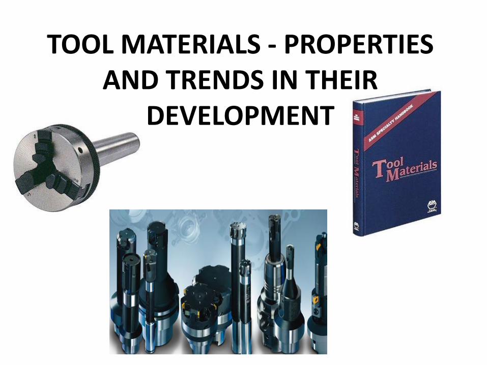
TOOL MATERIALS - PROPERTIES AND TRENDS IN THEIR
DEVELOPMENT
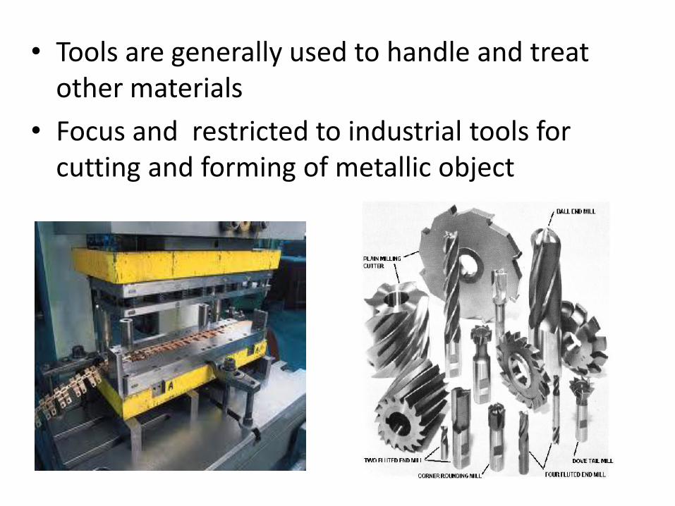
• Tools are generally used to handle and treat other materials
• Focus and restricted to industrial tools for cutting and forming of metallic object
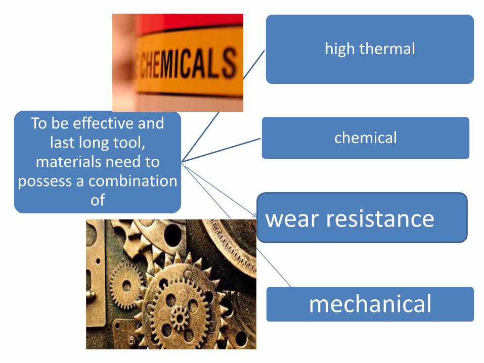
To be effective and last long tool,
materials need to possess a combination
of
high thermal
chemical
mechanical
wear resistance
• each tooling operation requires an optimised combination of these properties, the number of different tool materials is very high.
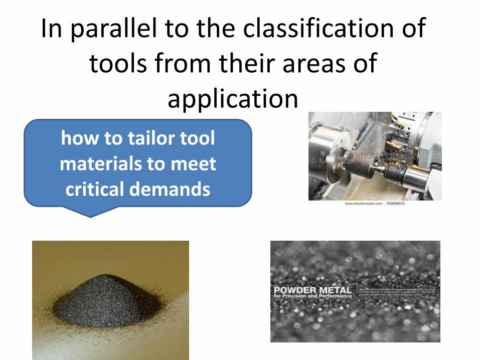
In parallel to the classification of tools from their areas of
application
how to tailor tool materials to meet critical demands

Example:
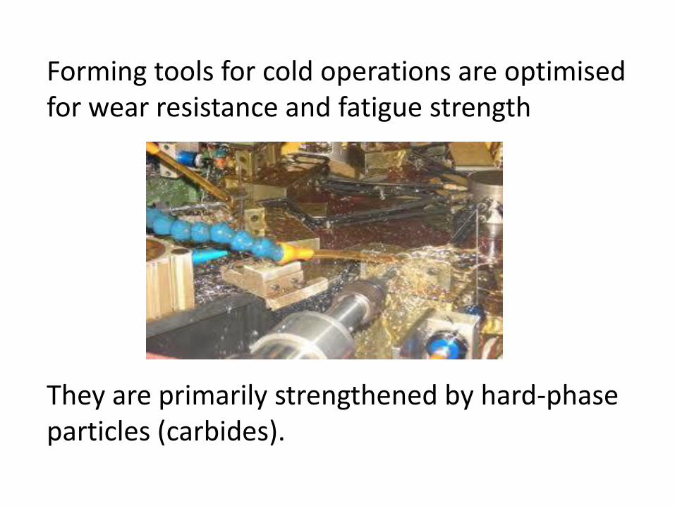
Forming tools for cold operations are optimised for wear resistance and fatigue strength They are primarily strengthened by hard-phase particles (carbides).
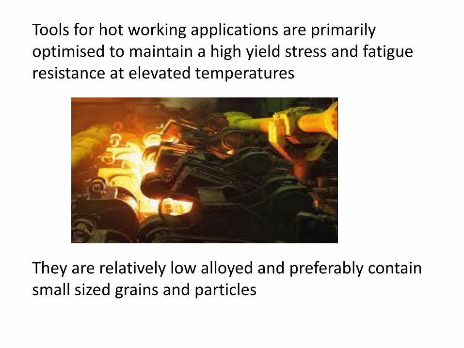
Tools for hot working applications are primarily optimised to maintain a high yield stress and fatigue resistance at elevated temperatures They are relatively low alloyed and preferably contain small sized grains and particles
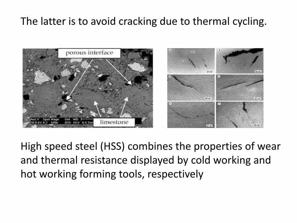
The latter is to avoid cracking due to thermal cycling. High speed steel (HSS) combines the properties of wear and thermal resistance displayed by cold working and hot working forming tools, respectively
Both HSS and hot work tool steel are today usually made from powder in order to get a homogeneous composition and small sized grains and particles. Most often, edge wear limits the life of cutting tools where as work material adhesion (galling) usually limits forming tool life Galling usually refers to the adhesive wear Both factors deteriorate the quality of the product
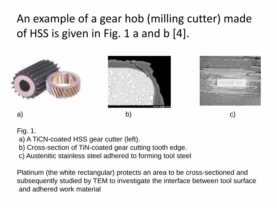
An example of a gear hob (milling cutter) made of HSS is given in Fig. 1 a and b [4].
a) b) c)
Fig. 1.
a) A TiCN-coated HSS gear cutter (left).
b) Cross-section of TiN-coated gear cutting tooth edge.
c) Austenitic stainless steel adhered to forming tool steel
Platinum (the white rectangular) protects an area to be cross-sectioned and
subsequently studied by TEM to investigate the interface between tool surface
and adhered work material
c) Austenitic stainless steel adhered to forming tool steel
Body
Locating devices
Clamping devices
Tool guide (jigs bushing)
The jig body is generally made of cast iron by casting process or fabricated by welding together various slabs and bars of mild steel.
It may be heat treated to relief the stresses. Body is the most prominent feature of the jig. Its main purpose is to support and house the job. The various jig body are follows:
Plane Type Jig: Plane type jig is the simplest type; it is used
when plane holes are to be drilled. It has either drill bushes for guiding the tools or the holes without bushes.
Channel Type Jig: Channel type is made up from standard
steel channel section.
Box type Jig:
Box type jig is used where a component
requires drilling in more than one plane
and the jig is to be provided with on
equitant number of drill bush plates. One
side of the box is fitted with a lid which
can be opened for inserting the
component and for unloading it. It should
be made as light as possible.
The Built Up Jig: The built up jig used dowels and screws
for fabricating member welded type. Standard steel sections are used in it for the limited numbers of details, which are secured by means of screws and dowels, the locating pins and the blocks are positioned so that the greatest dimensional variation of the work piece may be accommodated.
Leaf Type Jig: Leaf type jig is simple made from a block of
steel fitted with two adjustable locating screws and a spring loaded plunger. It is used in case of measured large components where it may be both unnecessary and construct a jig to hold the complete component, where madding is purely confined to a local section of the work piece.
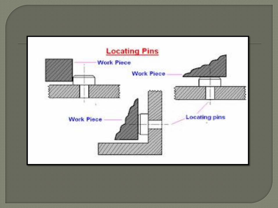
The pins of various design and made of hardened steel are the most common locate devices used to locate a work piece in a jig or fixture.
The shank of the pin is press fitted or driven into the body of jig or fixture.
The locating diameter of the pin is made larger than the shank to prevent it from being forced into the jig or fixture body due to the weight of the work piece or cutting forces.
Depending upon the mutual relation
between the work piece and the pin. The
pin may be classify as follows:
Locating Pins:
When reamed or finally finished holes are
available in work piece, these can be used
for locating purpose of the manner as
shown , these are two types of locating pins:
Conical locating pins
Cylindrical locating pins
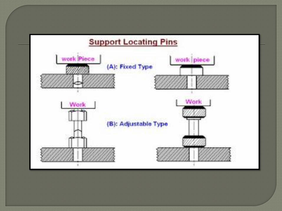
Support Locating Pins: With these pins (also known as rest pins)
buttons or pads the work piece with flat surfaces supported at convenient. In the fixed support pins the locating face is either ground flat or curved. Support pins with flat head are usually employed and provided location and support to machine surface, because more contact area is available during location.
Jack Pins: Jack pins or spring pins are also used to
locate the work piece whose dimension are subjected to variation. The pin is allow to come up under spring pressure or conversely is pressed down by the work piece. When the location of the work piece is secured the pin is locked in this position by means of locking screw.
If the work piece can not be restrained by the locating devices or elements, it becomes necessary to clamp the work piece in jig or fixture body.
The most common example of clamping devices is bench vice. The purpose of the clamping is to exert a pressure to press a work piece against the locating surfaces and hold it there in a position to the cutting forces.
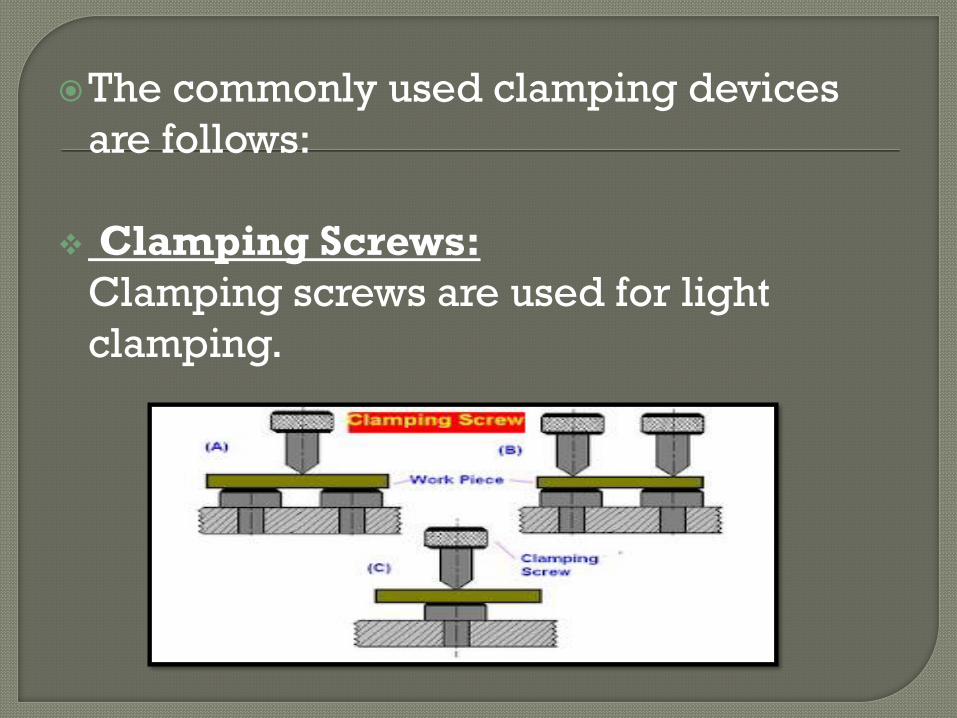
The commonly used clamping devices
are follows:
Clamping Screws:
Clamping screws are used for light
clamping.
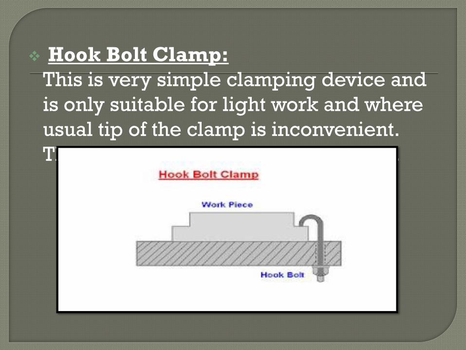
Hook Bolt Clamp:
This is very simple clamping device and
is only suitable for light work and where
usual tip of the clamp is inconvenient.
The typical hook bolt clamp is shown.
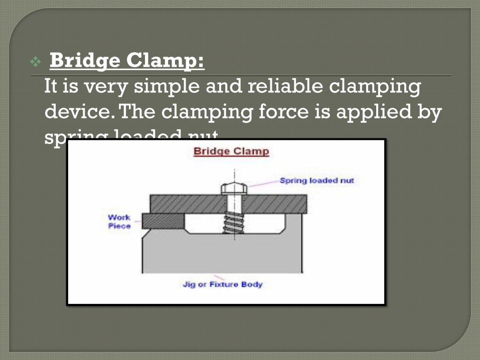
Bridge Clamp:
It is very simple and reliable clamping
device. The clamping force is applied by
spring loaded nut.
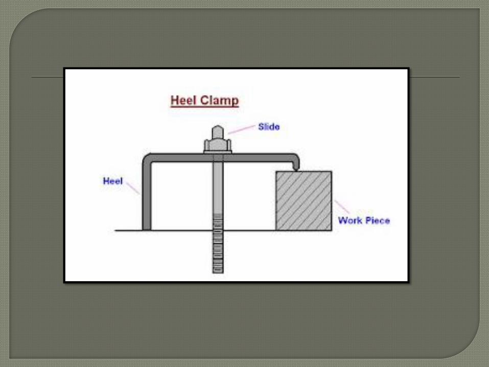
Heel Clamp: These consist of a rusted plate, centre stud
and heel. This trap should be strengthening at the point where the hole for the stud is cut out, by increasing the thickness around the hole. The design differ from simple bridge clamp in that a heel is provided at the outer end of the clamp to guide its sliding motion for loading and unloading the work piece.
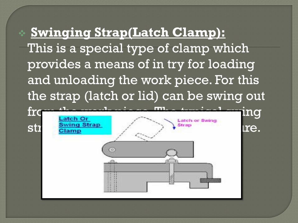
Swinging Strap(Latch Clamp):
This is a special type of clamp which
provides a means of in try for loading
and unloading the work piece. For this
the strap (latch or lid) can be swing out
from the work piece. The typical swing
strap or latch clamp is shown in figure.
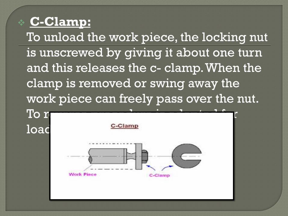
C-Clamp:
To unload the work piece, the locking nut
is unscrewed by giving it about one turn
and this releases the c- clamp. When the
clamp is removed or swing away the
work piece can freely pass over the nut.
To reverse procedure is adopted for
loading the work piece.
Then to locate the tool relative to the work, use is made of guiding parts such as jigs bushing and templates. These must be precise, were resistance and changeable.
Jig bushes are used in drilling and boring, a bush fits into the hole of the jig, through which the drill passes.
The diameter of the bush depends on the diameter of the drill. Different type of bushes is spot welded or screwed with the jig. Headless type bushes are press fit into the hole of the job.
a) Press fit wearing bushes:
These bushes are used when little
importance in put on accuracy or finish
and tool used is a twist drill.
These bushing are installed directly in
the jig body and are used mainly for
short protection. There are two design of
press fit bushing:
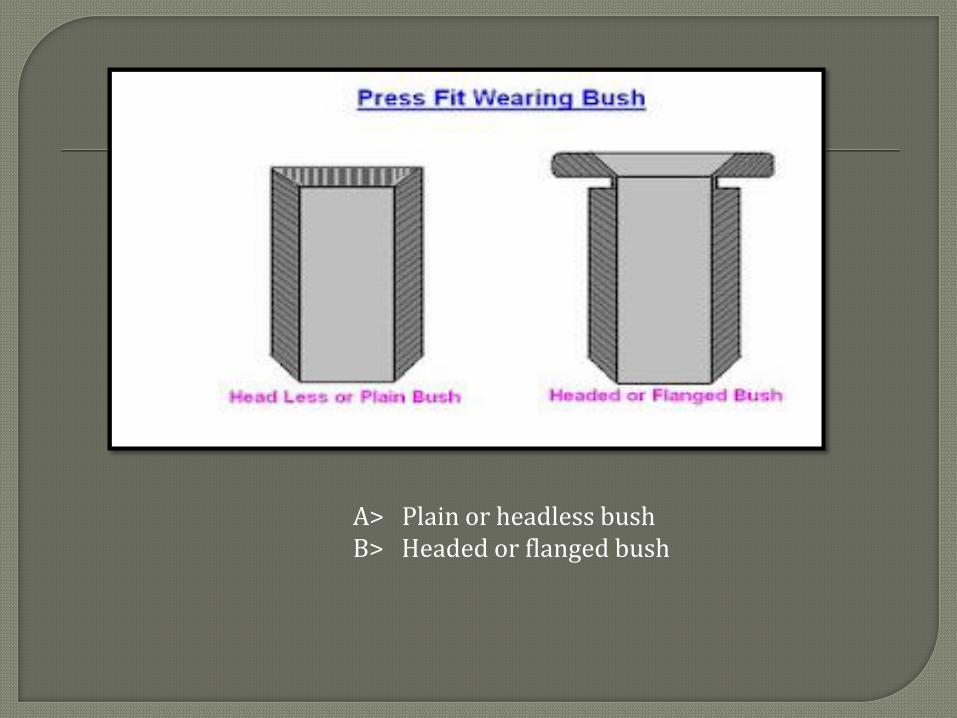
A> Plain or headless bush B> Headed or flanged bush
b) Renewable bushes:
When the guide bushes requires
periodic replacement (due to wear of the
inside diameter of the bush). Its
replacement is simply by using a
renewable bush.
These are of the flanged types and
sliding fit into the linear bush, which is
installed press fitted into the jig plate.
The linear bush provides hardened wear
resistance, mating surface to the
renewable bush.
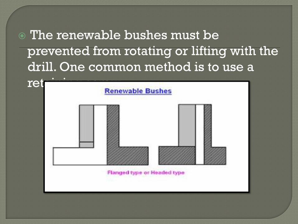
The renewable bushes must be
prevented from rotating or lifting with the
drill. One common method is to use a
retaining screw.
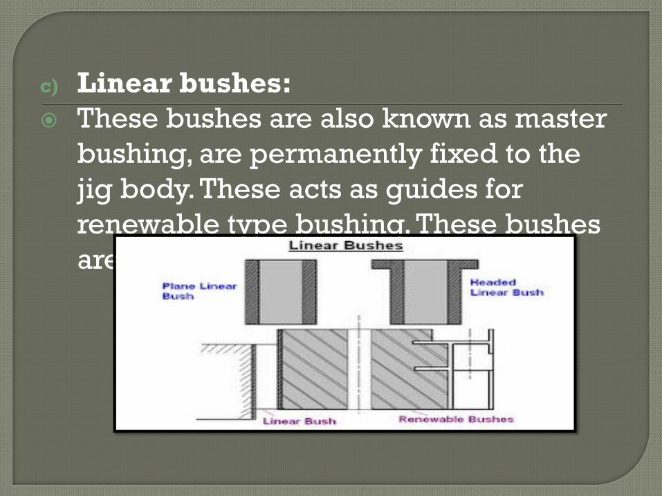
c) Linear bushes:
These bushes are also known as master
bushing, are permanently fixed to the
jig body. These acts as guides for
renewable type bushing. These bushes
are be with or without head.
1. Full-automatically control
In the process of combination produce,
every machine recognize work condition
automatically, full control the product
line.
2. High precision, Stable performance
Erro-correcting in position make up the
erro of servo system added up in the
process of produce, make sure works
with stable and precision for a long Time.
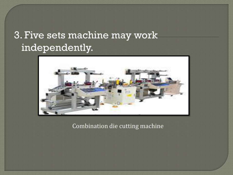
3. Five sets machine may work
independently.
Combination die cutting machine