Embed Size (px)
Citation preview

Faculty of Electrical Engineering, Mathematics and Computer Science Software Engineering Group
Tool support for the selection of alternatives in MDA model transformations
Chris Scheffers
date June 10th, 2005
committee Prof. dr. ir. Mehmet Aksit
Dr. Ivan Kurtev Dr. ir. Klaas van den Berg

Tool support for the selection of alternatives in MDA model transformation
2
Abstract An important concept in the Model-Driven Architecture is the transformation of models. One specific type of model transformation is metamodel-based transformation. This type of model transformation specifies the transformation using concepts from the metamodel of the source model that has to be transformed and from the target metamodel. This approach makes it possible the reuse the same transformation specification with a wide range of source and target models that are instances of the metamodels used in the transformation specification.
When defining the transformation of metamodel constructs, there will most likely be more possible candidate constructs from the target metamodel to represent a source metamodel construct. This one-to-many relation between source and target metamodel constructs leads to many different target models, all representation of the same source model. These target models may differ in the quality properties they have and most likely not all target models, obtained by mapping individual source to target constructs, will be valid models also.
To model all these possible transformations, concepts from a technique called design algebra are used. This technique makes it possible to model the alternatives without generating them all, which is necessary when the number of alternatives is too large to store. So before alternatives can be presented, their number has to be reduced. This can be done by applying heuristic rules that exclude or select certain sets of alternatives or by excluding all invalid target models. Heuristic rules can also make use of certain quality properties target models may have.
This whole process of modeling and reducing the number of alternative transformations requires much work. A large part of this process could be supported by a tool, taking care of the modeling of alternatives given a certain source model, applying heuristic rules that make use of the desired quality properties and present a reduced set of alternatives.
The development of such a tool is the aim of this project.
The first phase in this development consists of the evaluation of the existing process for the selection of alternative transformation with the help of design algebra and a more detailed definition of the process, more suitable to be supported by a tool. Special attention is paid to the role that patterns play and how these patterns can be integrated into the process. Also important is that the tool should not be limited to one combination of source and target model types, but should support a wide range of model transformation.
The result of the development process is a tool capable of supporting the selection of alternative transformations with all the requirements and details mentioned above. The tool uses the Eclipse Modeling Framework (EMF) to handle the source model (Ecore) in combination with the Kent OCL Library to query the source model using the Object Constraint Language (OCL). The modeling of alternatives and the reduction of the number of alternatives are realized using a Prolog implementation. The interface with the user is provided by an application written in Java, connecting the EMF, OCL and Prolog components together. The tool does not cover the whole process defined in this thesis, but a large part of the first phase in alternatives generation is supported. Two case studies show that the tool can be successfully used to support the selection of alternative transformations from a UML class diagram to Java code and from a UML class diagram to a XML schema. The transformations modeled by the tool have to be refined further to define a complete transformation from source to target model.

Chapter 1: Introduction
3
Preface

Tool support for the selection of alternatives in MDA model transformation
4
Abbreviations API Application Program Interface ArTiST Alternative Transformation Selection Tool CASE Computer-Aided Software Engineering CHR Constraint Handling Rules CIM Computer Independent Model CMOF Complete MOF CORBA Common Object Request Broker Architecture CUP Constructor of Useful Parsers CWM Common Warehouse Metamodel EMF Eclipse Modeling Framework EMOF Essential MOF FAQ Frequently Asked Questions FLWOR For Let Where Order Return GUI Graphical User Interface IDE integrated development environment IDL Interface Definition Language IIOP Internet Inter-ORB Protocol J2EE Java 2 Platform, Enterprise Edition J2SE Java 2 Platform, Standard Edition JAR Java Archive JFC Java Foundation Classes JMI Java Metadata Interface JNI Java Native Interface JPL Java Prolog Library? KMF Kent Modeling Framework MDA Model-Driven Architecture MDR Metadata Repository MOF Meta Object Facility OCL Object Constraint Language OMG Object Management Group PIM Platform Independent Model PSM Platform Specific Model QVT Query / Views / Transformations RFP Request For Proposals SDK Software Developer Kit SDO Service Data Objects TSAS Telecommunication Service Access and Subscription UML Unified Modeling Language VM Virtual Machine W3C Word Wide Web Consortium XMI XML Metadata Interchange XML Extensible Markup Language XSD XML Schema Definition XSLT Extensible Stylesheet Language Transformation

Chapter 1: Introduction
5
Table of contents 1 Introduction ........................................................................................................................7
1.1 Background .................................................................................................................71.2 Scope ..........................................................................................................................81.3 Problem statement ....................................................................................................101.4 Outline ......................................................................................................................10
2 Concepts ..........................................................................................................................122.1 Model-Driven Architecture (MDA) .........................................................................12
2.1.1 MDA specified ...............................................................................................122.1.2 MDA in software processes ...........................................................................142.1.3 Metamodel-based transformations in MDA ...................................................14
2.2 Design Algebra .........................................................................................................152.2.1 Automated support: Rumi ...............................................................................162.2.2 Transformation spaces ....................................................................................18
2.3 Meta Object Facility (MOF) and related concepts ...................................................192.3.1 Meta Object Facility (MOF) 2.0 .....................................................................192.3.2 Object Constraint Language (OCL) 2.0 .........................................................202.3.3 Query / Views / Transformations (QVT) .......................................................212.3.4 Ecore ...............................................................................................................21
3 UML to XML transformations ........................................................................................233.1 Introduction ..............................................................................................................233.2 Example: examination questionnaires ......................................................................24
3.2.1 Skeleton generation ........................................................................................243.2.2 Skeleton refinement ........................................................................................29
3.3 Evaluation .................................................................................................................324 UML to Java transformations ..........................................................................................33
4.1 Source model ............................................................................................................334.2 Target models ...........................................................................................................33
4.2.1 Quality requirements ......................................................................................344.2.2 Patterns ...........................................................................................................34
4.3 Process definition .....................................................................................................384.3.1 Activity 1 - Create target skeleton space ........................................................394.3.2 Activity 2 - Assign quality requirement .........................................................404.3.3 Activity 3 - Reduce target skeleton space ......................................................414.3.4 Activity 4 - Validate target skeleton space .....................................................424.3.5 Activity 5 - Select target skeleton alternative .................................................424.3.6 Activity 6 - Refine target skeleton alternative ................................................43
4.4 Example 1: library ....................................................................................................444.4.1 Activity 1 - Create target skeleton space ........................................................444.4.2 Activity 3 - Reduce target skeleton space ......................................................494.4.3 Activity 4 - Validate target skeleton space .....................................................504.4.4 Activity 5 - Select target skeleton alternative .................................................524.4.5 Activity 6 - Refine target skeleton alternative ................................................52
4.5 Example 2: library with run-time adaptable algorithms ...........................................574.5.1 Activity 1 - Create target skeleton space ........................................................584.5.2 Activity 3 - Reduce target skeleton space ......................................................604.5.3 Activity 2 - Assign quality requirement .........................................................604.5.4 Activity 3 - Reduce target skeleton space (2) .................................................604.5.5 Activity 4 - Validate target skeleton space .....................................................614.5.6 Activity 5 - Select target skeleton alternative .................................................624.5.7 Activity 6 - Refine target skeleton alternative ................................................62
4.6 Example 3: library with run-time extensible operations ...........................................674.6.1 1. create target skeleton space ........................................................................67

Tool support for the selection of alternatives in MDA model transformation
6
4.6.2 2. reduce target skeleton space .......................................................................694.6.3 3. assign quality requirements ........................................................................694.6.4 3. reduce target skeleton space (using quality properties) ..............................704.6.5 4. validate space .............................................................................................714.6.6 5. select coordinate .........................................................................................714.6.7 6. refinement ...................................................................................................71
4.7 Evaluation .................................................................................................................735 Tool development ............................................................................................................74
5.1 Requirements ............................................................................................................745.1.1 Activity diagrams ...........................................................................................745.1.2 Use cases ........................................................................................................745.1.3 Informal requirements ....................................................................................755.1.4 GUI design .....................................................................................................79
5.2 Analysis ....................................................................................................................795.2.1 Generalize requirements .................................................................................795.2.2 Architecture ....................................................................................................805.2.3 Implementation techniques .............................................................................81
5.3 Design .......................................................................................................................855.3.1 Conceptual data model ...................................................................................855.3.2 Partial development ........................................................................................875.3.3 Data model .....................................................................................................87
5.4 Implementation .........................................................................................................905.4.1 Required packages ..........................................................................................905.4.2 Implementation details ...................................................................................91
5.5 Testing ......................................................................................................................945.5.1 Requirements ..................................................................................................955.5.2 Case study: Library example 2 .......................................................................965.5.3 Case study: Examination Questionnaires .....................................................108
5.6 Evaluation ...............................................................................................................1126 Conclusions and recommendations ...............................................................................113
6.1 Conclusions ............................................................................................................1136.2 Recommendations ..................................................................................................113
A GUI design .....................................................................................................................118
A.1 Activity 1 - Create target skeleton space ................................................................118A.2 Activity 2 - Assign quality requirement .................................................................119A.3 Activity 3 - Reduce target skeleton space ..............................................................121A.4 Activity 4 - Validate target skeleton space .............................................................123A.5 Activity 5 - Select target skeleton alternative .........................................................125A.6 Activity 6 - Refine target skeleton alternative ........................................................125

Chapter 1: Introduction
7
1 Introduction This chapter describes the problem addressed in this thesis and the approach to a solution for the problem. First the background is discussed briefly, then the context is described and the scope of the problem domain is defined, followed by the problem statement and an approach to solve the problem. Some of the concepts used in this chapter are further explained in Chapter 2: Concepts.
1.1 Background The Model-Driven Architecture (MDA) provides an approach for specifying a system independently of the platform that supports it and for transforming the system specification into one for a particular platform. One has to think about a platform as a relative concept, where it is possible to have multiple platforms on top of each other. Examples of a system specification are: a set of requirements, a UML class diagram, a program written in Java, etc. The key part of MDA is model transformation, where a system specification is transformed into one for a particular platform. There are different types of model transformations; one of them is metamodel-based transformation. Metamodel-based transformations define the transformation between two models using concepts from their metamodels. This makes it possible to use the same transformation specification for different instances of the metamodels used. Some examples of metamodel-based transformations are: UML to Java, UML to XML Schema, but also UML to UML or Java to C++.
Figure 1 – Multiple alternative target models using metamodel-based transformation,
taken from [12] (Figure 1)
When transforming one model into another model, usually many different transformations are possible. Consider the transformation of a conceptual UML class diagram to a Java program. When looking at Figure 1, the source model would be the UML class diagram, the source metamodel would be UML metamodel, the target metamodel would be a metamodel for Java programs, for example a model derived from the Java Language Specification, and the alternative target models would be Java programs. Because the UML class diagram is meant to be conceptual, a UML Class can not only be transformed into a Java Class, but also into a Java Interface, or a combination of these two Java constructs, etc. This is visible in the figure by the associations between one source metamodel element, for example MCA, and multiple target metamodel elements, for example MC1A and MC2A. So there are multiple alternative representations possible, often called mappings, of one source metamodel element in the target metamodel. These alternative mappings lead to multiple alternative target models that are all representations of one single source model.

Tool support for the selection of alternatives in MDA model transformation
8
Different alternative target models can have different quality properties. When in the example mentioned above a UML Class is mapped to combination of a Java Interface and Class (related by an implementation relation in a pattern), the target model has an extra quality property, namely run-time adaptability of the target model concept that represents the Class in the source model.
Both source and target metamodels impose constraints on the possible transformations. Not all available target model constructs are suitable to represent a source model construct (a Java Interface cannot keep properties or have operations) and not all combinations of target model constructs result in a valid target model (a Java Method cannot implement a Java Interface). When a systematic approach is used to consider all possible transformations, there will be a large amount of alternatives to evaluate. A concept called design algebra will be used to model the initial set of alternatives and to reduce the number of alternatives, by imposing reduction operations on the set. These reduction operations can make use the constraints of the source and target metamodels and heuristic rules, for example based on required quality properties of the target model. Because of the initial large amount of alternatives and the systematic way of reducing the number of alternatives with reduction operations, it is not a pleasant task to perform this whole selection process by hand. Fortunately, most of the selection process can be supported by a tool.
This thesis is based on the work described in two master theses, one from Gunawan [10] and the other from Sari [23], where the work of Sari is based on that of Gunawan. Both theses consider the transformation of UML class diagrams into XML schemas. Gunawan focuses on the identification of all possible mappings and on how the source model can be marked to guide the transformation process. Sari completes the identification of possible mappings and introduces heuristic rules to reduce the number of alternatives using design algebra (Gunawan also used design algebra, but not to model the transformation alternatives of whole model).
The focus of this project is more on the selection of alternative transformations than on the actual transformation of the models. Therefore the examples included in this thesis that deal with UML class diagram to Java code transformation should not be seen as a complete overview, but more as a first attempt for a transformation specification from UML to Java.
1.2 Scope The diagram below shows the mapping from UML Model into XML Schema as is performed by Sari. UML Profile is used to represent the alternatives. The UML Model and Profile are transformed into an XML Schema by using XSLT documents that use the included UML Profile for guidance.
Chapter 1: Introduction
9
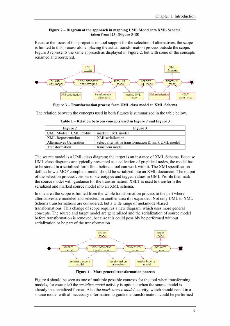
Figure 2 – Diagram of the approach in mapping UML Model into XML Schema, taken from [23] (Figure 3-18)
Because the focus of this project is on tool support for the selection of alternatives, the scope is limited to this process alone, placing the actual transformation process outside the scope. Figure 3 represents the same approach as displayed in Figure 2, but with some of the concepts renamed and reordered.
Figure 3 – Transformation process from UML class model to XML Schema
The relation between the concepts used in both figures is summarized in the table below.
Table 1 – Relation between concepts used in Figure 2 and Figure 3
Figure 2 Figure 3 UML Model + UML Profile marked UML model XML Representation XMI serialization Alternatives Generation select alternative transformation & mark UML model Transformation transform model
The source model is a UML class diagram; the target is an instance of XML Schema. Because UML class diagrams are typically presented as a collection of graphical nodes, the model has to be stored in a serialized form first, before a tool can work with it. The XMI specification defines how a MOF compliant model should be serialized into an XML document. The output of the selection process consists of stereotypes and tagged values in UML Profile that mark the source model with guidance for the transformation. XSLT is used to transform the serialized and marked source model into an XML schema.
In one area the scope is limited from the whole transformation process to the part where alternatives are modeled and selected; in another area it is expanded. Not only UML to XML Schema transformations are considered, but a wide range of metamodel-based transformations. This change of scope requires a new diagram, which uses more general concepts. The source and target model are generalized and the serialization of source model before transformation is removed, because this could possibly be performed without serialization or be part of the transformation.
Figure 4 – More general transformation process
Figure 4 should be seen as one of multiple possible contexts for the tool when transforming models, for example0 the serialize model activity is optional when the source model is already in a serialized format. Also the mark source model activity, which should result in a source model with all necessary information to guide the transformation, could be performed

Tool support for the selection of alternatives in MDA model transformation
10
in another way or omitted. The marking the source model is not necessary when the target model alternative contains all the information. When this is the case, there is no difference between selecting alternative transformations and selecting alternative target models. But in most cases not all information needed to create the target model is available in the alternative, so the source model is still needed. In this thesis the emphasize lays on the selection of alternative transformations, not target models, but the difference is not always that clear.
The tool which will help to select an alternative transformation can be placed at the position of the select alternative transformation activity in Figure 4. Before the development the tool can be started, the process that it should support must be well documented. The first part of the project consists of determining the process of alternatives selection, the second part consists of the actual development of the tool.
The process described by Sari is used as a starting point, but not everything is described in as much detail as is needed. Also a lot of decisions regarding heuristic rules require information from the user, who can interpret the source model, reason about relations and has insight into patterns. The tool however should be able to do as much as possible without requiring additional information from the user. This requires a well documented process.
Also the introduction of patterns will require extra attention, because in the process as defined by Sari this still requires a lot of input from the user. These patterns should be included in the process, because they make it possible to realize more quality properties, which can make the selection process easier. Especially target model patterns, which can introduce elements in the target model that are not present in the source model, need a way to be defined using only metamodel concepts.
The tool should be capable of supporting a wide range metamodel-based transformations; not only UML to XML Schema should be supported, but also transformations between other source and target model types as well.
1.3 Problem statement The aim of this project is to realize a tool that supports the selection of alternatives in MDA model transformations. To structure the research and to focus on some special points of interest, four objectives are distinguished: - define the process of alternatives selection - describe how patterns can be used in the process - determine a framework to handle a wide range of metamodel-based transformations - implemented a tool that supports the process defined, using the framework
1.4 Outline Chapter 2 provides a brief explanation of the most important concepts related to this project. The basics of the design algebra are explained, along with an overview of the available methods for model transformations using design algebra.
A more detailed view on the method used by Sari is provided in Chapter 3. The method is demonstrated in an example transformation from a UML class diagram to XML Schema. Afterwards the method is evaluated and some points for improvements are proposed, along with parts that require extra attention.
In Chapter 4 the process of alternative transformation selection is defined, taking the results from the evaluation of the exiting methods into account. A separate section describes to what extent and how patterns can be used in the selection process. The remainder of Chapter 4 shows the elaboration of three examples regarding UML to Java transformations. The usage of Java as target model type prevents the process being adapted to only one target metamodel. The first example illustrates the main execution of the process defined. The next two examples illustrate the use of patterns, of which the last example is the most complex one.

Chapter 1: Introduction
11
Chapter 5 covers the whole software development process of the tool, except for a part of the requirements phase that is already performed in Chapter 4. The chapter is divided into five phases: requirements, design, analysis, implementation and testing. Testing is only limited to the discussion of which requirements are covered by the implementation and the execution of two examples from Chapter 3 and 4.
The conclusions and recommendations are presented in Chapter 6.

Tool support for the selection of alternatives in MDA model transformation
12
2 Concepts In this chapter a brief explanation is provided of most important concepts related to this project. The transformations discussed in this thesis are part of the MDA process. To handle and reduce the set of alternative transformations design algebra is used. Rumi, an existing tool supporting design algebra, and the use of design algebra to support transformation, are also discussed. The Meta Object Facility (MOF) is chosen as a (metameta)model where all source models that should be supported by the tool must be compliant with. The decision to only support MOF compliant models makes it possible to use a well-defined language for querying the source models, for example the Object Constraint Language (OCL). Because currently no implementation exists that enables the evaluation of OCL over MOF compliant models, Ecore is chosen as (meta)metamodel. Ecore is part of the Eclipse Modeling Framework (EMF). Concepts not covered in this chapter are XML, XMI, UML and Java. XML and XMI are not used directly and are placed outside the scope of this project. UML and Java are not explained because it is assumed the readers of this report are familiar with the basics of these two concepts.
2.1 Model-Driven Architecture (MDA) The MDA specification describes a certain approach to system development, where models are the key artifacts. It describes what kind of models to use, how those models may be prepared and the relationships of the different kinds of models. One key characteristic of the MDA is the concept of model transformations. There are multiple ways to transform a source model into a target model; one of these ways is described in more detail the section about metamodel-based transformations in MDA.
2.1.1 MDA specified The Model-Driven Architecture (MDA) is defined by the Object Management Group (OMG). The OMG is an international nonprofit software consortium that is setting standards in the area of distributed object computing. It is a vendor-neutral membership-driven organization and has hundreds of members who are working towards developing and refining these standards. The process OMG manages consists of proposing technologies and inviting proposals and inviting feedback from any member company before coming to consensus on a final specification, which becomes an adopted standard. Some of the standards the OMG has developed include CORBA, UML and IIOP [15]. From the concepts used in this thesis MOF, UML, OCL, XMI and QVT (work in progress) are defined by the OMG. The MDA is OMG's next step in solving integration problems through open, vendor-neutral interoperability specifications. The MDA addresses integration and interoperability spanning the life cycle of a system from business modeling and design, to component construction, assembly, integration, deployment, management and evolution. [13]
The MDA is based on the well established idea of separating the specification of the operation of a system from the details of the way the system uses the capabilities of its platform. The MDA provides an approach for specifying a system independently of the platform that supports it, specifying platforms and choosing a particular platform for the system and transforming the system specification into one for a particular platform. The three primary goals of the MDA are portability, interoperability and reusability through architectural separation of concerns. [14]
Because the term platform is used quite often, it is important to look at with in more detail.
Platform The MDA Guide [14] states:

Chapter 2: Concepts
13
A platform is a set of subsystems and technologies that provide a coherent set of functionality through interfaces and specified usage patterns, which any application supported by that platform can use without concern for the details of how the functionality provided by the platform is implemented.
A platform is not one fixed level in a system, which is demonstrated in the following example: A PSM specific to the CORBA platform may hide the details of the programming language and the operating system. A PSM specific to CORBA Components may hide the details of CORBA along with the programming language and operating system. So it is possible to distinguish platforms on top of other platforms. CORBA and CORBA Components are examples of technology specific platforms, along with J2EE. Other examples of platform types are: generic platform types (object, batch, dataflow) and vendor specific platform types (IBM WebSphere and JBOSS regarding J2EE, Microsoft .NET).
The MDA distinguishes between three different kinds of models (also called viewpoints on a system): CIM, PIM and PSM. The idea is that these models are succeeded by each other, becoming more specific towards an implementation each time.
Computer Independent Model (CIM) The requirements for the system are modeled in a CIM, describing the situation in which the system will be used. Such a model is sometimes called a domain or business model. It may hide much or all information about the use of computer systems. It helps in presenting exactly what the system is expected to do, by showing the environment in which it will operate. The requirements in the CIM should be traceable to the PIM and PSM constructs that implement them, and vice versa.
Platform Independent Model (PIM) A PIM is a model with a high level of abstraction that is independent of any implementation technology, or at least exhibits a specified degree of platform independence to be suitable for use with a number of different platforms of similar type. A PIM describes a software system in the best way to supports some business. What modeling techniques are to be used is not defined.
Platform Specific Model (PSM) A PIM is transformed into one or more PSMs. A PSM is tailored to specify the system in terms of a specific implementation technology. The PSM models the same system as the one specified by the PIM, but is also specifies how that system makes use of the chosen platform. A PSM will be an implementation when it provides all the information needed to construct and deploy a system, or it may act as a PIM that is used for further refinement to a PSM that can be directly implemented.
Mapping Mapping is the specification of a mechanism for transforming the elements of one model into the elements of another model, i.e. the rules for a certain type of transformation. The MDA Guide [14] introduces two types of mappings, and a combination of these two: Model type mappings specify the transformation from models described in a certain PIM language to models using a specific PSM language.
Model instance mappings identify model elements in the PIM which should be transformed in a particular way, given the choice of a specific platform for the PSM. Marks can be added to the PIM to indicate how certain concepts of the PIM should be transformed to certain concepts in the PSM.
Most mappings consist of a combination of these two approaches. Besides marks, templates can be used in rules for transforming a pattern of model elements in a model type mapping
Tool support for the selection of alternatives in MDA model transformation
14
into another pattern of model elements. To describe a transformation of one model to another, different methods can be used: a description in natural language, an algorithm in an action language or in a model mapping language.
The current MOF 2.0 Query/View/Transformation RFP [18] (Request For Proposals) requests technology submissions suitable for the specification of model mappings. The submissions to this RFP will be discussed in Chapter 5.2.3, where the techniques to be used to implement the tool are evaluated.
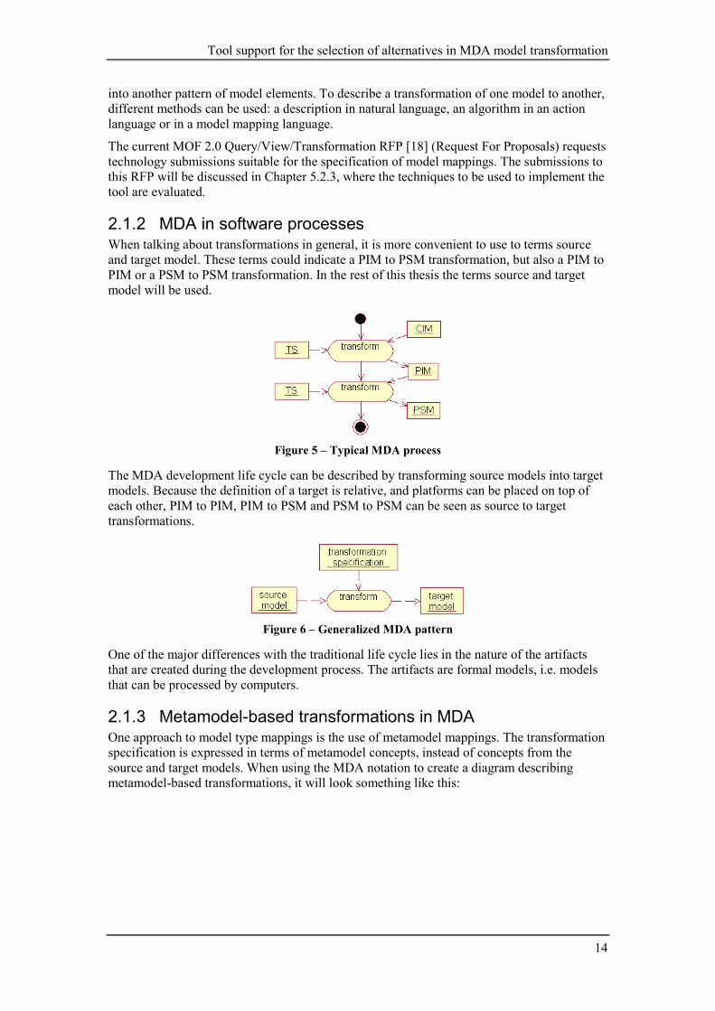
2.1.2 MDA in software processes When talking about transformations in general, it is more convenient to use to terms source and target model. These terms could indicate a PIM to PSM transformation, but also a PIM to PIM or a PSM to PSM transformation. In the rest of this thesis the terms source and target model will be used.
Figure 5 – Typical MDA process
The MDA development life cycle can be described by transforming source models into target models. Because the definition of a target is relative, and platforms can be placed on top of each other, PIM to PIM, PIM to PSM and PSM to PSM can be seen as source to target transformations.
Figure 6 – Generalized MDA pattern
One of the major differences with the traditional life cycle lies in the nature of the artifacts that are created during the development process. The artifacts are formal models, i.e. models that can be processed by computers.
2.1.3 Metamodel-based transformations in MDA One approach to model type mappings is the use of metamodel mappings. The transformation specification is expressed in terms of metamodel concepts, instead of concepts from the source and target models. When using the MDA notation to create a diagram describing metamodel-based transformations, it will look something like this:

Chapter 2: Concepts
15
Figure 7 – MDA metamodel-based transformation
What is not visible in the diagram above, are the various alternative target models which can be obtained from one source model. In Figure 8 the same transformation process is shown, but now with the different possible transformations resulting in multiple target models visible.
Figure 8 – Multiple alternative transformations with one source model,
taken from [12] (Figure 1)
The source and target models are situated at level M1 according to the MOF terminology and their metamodels are situated at level M2. Model MA is an instance of source metamodel MMA and has to be transformed to an instance of the target metamodel MMB. Most of the constructs in the source metamodel can be mapped to multiple constructs in the target metamodel. For example construct MCA in the source metamodel MMA can be mapped to either MC1B or MC2B in the target metamodel MMB. So for each instance of metamodel construct MCA in the source model, there are alternative mappings to different metamodel constructs possible. These alternative mappings give raise to multiple target models all originating from the same source model. When considering models representing real world problems, the amount of these alternative transformations can become enormous.
2.2 Design Algebra To handle all possible alternatives in MDA transformations, a systematic approach is needed. This approach is realized by using concepts from a technique called design algebra.
Design algebra is a technique for modeling design spaces and balancing design alternatives. Design algebra is an application of relational algebra, which manipulates relations. A design space is defined as a multi-dimensional space from which the set of alternatives for a given design problem can be derived. A design space may be defined for every concept in a solution domain. A design space is spanned by an independent set of dimensions. A dimension represents a sub-concept of a concept from the solution domain. Each dimension has a set of

Tool support for the selection of alternatives in MDA model transformation
16
coordinates, which represents the set of properties that maybe assigned to a sub-concept. A design alternative represents a point in the design space, containing one coordinate from each dimension.
To make the technique more concrete, the next section presents an elaborated example using design algebra guided by tool support.
2.2.1 Automated support: Rumi Rumi is the name of the tool available for supporting design algebra. The tool is implemented in VisualWorks and not supported anymore, but a short overview is presented to show how design algebra works and can be supported by a tool.
Figure 9 – Rumi – Launcher window
Rumi contains four basic tools for working with design algebra: model definer, design space composer, alternatives quantifier and alternatives generator. The tool will be explained on the basis of the Scheduler example model in Tekinerdogan [28] (ch.5.3,ch.5.6). A property set definer is added to the set of tools to manage property sets.
Model definer In the model definer models can be constructed. A model consists of concepts and relations between these concepts. Scheduler is an example of such a model. The Scheduler model consists of the concepts Synchronization Scheme (Sch), Synchronization Strategy (Str) and Performance Failure Detector (PFD). Sch is related to both Str and PFD. In the rest of this example the relations between the concepts are discarded.
Formal description of the Scheduler model: MScheduler = (Sch, Str, PFD)
Property set definer The tool seems to lack the support of a separate property set definer. In this definer the property sets should be managed, such as the Object property set, containing the properties class (CL), operation (OP) and attribute (AT) and the Adaptability property set containing fixed (FX), compile-time (ADc) and run-time (ADr). To each of these (quality) properties a priority can be attached, which is used for ordering the alternatives during the alternatives generation. No priorities are used in this example.
Definition of the Object property set: PObject = (CL, OP, AT) Definition of the Adaptability property set: PAdaptability = (FX, ADc, ADr)

Chapter 2: Concepts
17
Design space composer The design space composer supports the design algebra techniques for composing design spaces. A design space can be constructed by applying a Cartesian product (other operations are possible) on a selected model and a selected property set.
Figure 10 – Architecture of Rumi
Tekinerdogan also uses the term tuple space besides the term design space; the space contains all possible tuples between concepts from the model and properties from the property sets.
Create two design spaces, one with the concepts from Scheduler and properties from Object and the other with concepts from Scheduler and the properties from Adaptability: SObjectScheduler :: MScheduler → PObject
SAdaptableScheduler :: MScheduler → PAdaptability More complex design spaces can also be constructed, for example an adaptable object design space for a scheduler: SAdaptableObjectScheduler :: MScheduler → (PAdaptability × PObject)
Alternatives quantifier The alternatives quantifier can be used to assign different priority numbers to individual tuples. One can also use the priorities assigned to the individual properties of property sets in combination with operations like addition or multiplication to automatically calculate priorities for all tuples.
To denote that the Synchronization Scheme should be preferably run-time adaptable, one could assign a priority value of 10 to the tuple (Sch, ADr): SAdaptableScheduler :: {(MScheduler × PAdaptability) → N | (Sch, ADr) 10}
Alternatives generator The tool can be used to generate all possible alternatives from the design space, but only when the number of alternatives is small enough. The result is a list of all alternatives presented as tuples, ordered by their priority value. To decrease the number of alternatives, the tool offers two ways to accomplish this: matrix-based and rule-based alternatives selection.
Matrix-based alternatives selection tool Matrix-based selection does not list all alternatives of the design space, but all elements from which the alternatives are constituted. The selection of these elements corresponds to the selection of coordinates.

Tool support for the selection of alternatives in MDA model transformation
18
The construction of the matrix ObjectScheduler is defined as: CObjectScheduler :: MScheduler × PObject
Rule-based alternatives selection tool For every concept a question window is presented where one can choose between the properties of a property sets. This is more or less the same as the matrix-based approach, but in a more user friendly way. On the other hand, the matrix-based selection tool can be experienced as more orderly.
Other selection methods Besides the two selection tools discussed above, design algebra offers more ways to reduce the number of alternatives: - selection of a sub-space
o direct selection directly select alternatives from the space
o selection based on conditional specifications a condition can be constructed using functions like , ∧ , ∨ and ¬ example where Scheduler should be represented by a Class or an Operation: SRObjectScheduler :: {MScheduler → PObject | (Sch CL) ∨ (Sch OP)}
o matrix based-selection - elimination of a sub-space
the same methods as described for selection of a sub-space, but then the sub-space is excluded instead of selected
- heuristic-based selection and/or elimination o conditional statements in the form of: IF <condition> THEN <consequent>
no formal syntax for <condition> or <consequent> is proposed
2.2.2 Transformation spaces The same concepts used in design algebra can be used for modeling alternative transformations and balancing between these alternatives. Instead of a design space, a transformation space is created, which models all possible alternative transformations given a certain source model. Besides a transformation space, quality model spaces can be created to model the possible quality properties desired for the target model. Heuristic rules can use selected quality model alternatives to reduce the number of alternative transformations.
The most detailed description and demonstration of model transformations using transformation spaces is described by Sari [23]. This method is based on the work described in Kurtev [12]. An overview of both methods is presented below, followed by the differences between both methods and design algebra. A more detailed look on the method used by Sari is presented in chapter 3, where an example transformation from UML to XML is performed.
The process of constructing and utilizing a transformation space consists of four steps [12]: 1) Construction of Transformation Space
A transformation space is defined, the dimensions spanning the space are determined based on the source model elements and for each dimension a coordinate set is determined, based on the possible target metamodel components. Possible constraints for the target models can be defined in the step also.
2) Reducing transformation space With the help of the operations select and exclude, the design space can be narrowed down. All valid combinations can be selected and all invalid combinations can be excluded from the space. Selections can be based on heuristic rules, such as the ones defined by Sari for the mapping of UML class diagram to XML schema.
3) Reducing Transformation Space on the base of quality properties In this step the quality properties are placed in another space, which has the same

Chapter 2: Concepts
19
dimensions as the transformation space. The desired properties can be selected from the space, resulting in an alternative. This alternative is merged with the transformation space, so heuristic rules can use these properties to select certain alternatives.
4) Refinement A selected transformation alternative does not represent a complete transformation yet, but only an outline (skeleton) of a complete transformation. Probably each concept in the selected alternative requires additional tuning.
Some differences between the two methods described in the overview (Kurtev and Sari) and design algebra (Tekinerdogan) are presenting in the list below. After each difference is explained the preferred method is suggested in italics. - Tekinerdogan uses the addition of priorities to properties and individual tuples to create
an ordered list of alternatives (quantification). The initial version of the tool will not support this quantification of properties.
- Kurtev and Sari treat relations as concepts, which also have alternatives. Tekinerdogan uses separate relations between concepts (couplings). Relations will be handles just like concepts, so no separate step for selecting couplings between concepts is needed.
- Kurtev introduces a table that holds constraints on the allowed relations between components. Sari does not mention these constraints, maybe because they are applied until the refinement step, which is discussed only briefly in Sari. Constraints are used by Sari implicitly when defining all mappings for source model concepts. A separate step will be introduced in the process where all alternatives in the reduced transformation space will be validated against a metamodel or constraint table, validating the whole alternative instead of the separate components.
- Kurtev does not elaborate much on the refinement of the selected transformation space. Sari analyses this step further (based on Gunawan), but does not discuss it with much detail in the case study. The refinements step will be elaborated further when developing the tool.
- Kurtev merges the selected quality properties with the transformation space. This merging of spaces will be removed from the process, so the quality properties are kept separated from the possible mappings.
2.3 Meta Object Facility (MOF) and related concepts In this chapter various concepts are discussed, which are all related to the MOF in one way or another. First the MOF itself is introduced, along with JMI, which is based on the MOF but concentrated on the Java platform. Then OCL is discussed, which is not directly related to MOF, but a subset of OCL is. The QVT proposals and review are discussed next, along with XML Path and XQuery, both query languages suggested by the proposals (along with OCL). Then XMI, a description how to serialize MOF compliant models, is explained; followed by Ecore, a simplified version of MOF for tool integration.
2.3.1 Meta Object Facility (MOF) 2.0 A metamodel is a model used to model modeling. The MOF model is used to model itself as well as other models and other metamodels, such as the Unified Modeling Language (UML) and Common Warehouse Metamodel (CWM). MOF also serves as a platform-independent metadata management foundation for MDA.
Metamodels provide a platform independent mechanism to specify: - shared structure, syntax and semantics of technology and tool frameworks as metamodels - shared programming model for any resultant metadata (using Java, IDL, etc) - shared interchange format (using XML)

Tool support for the selection of alternatives in MDA model transformation
20
The shared programming model and interchange formats can be generated using standardized mappings such as XMI and JMI which are transformations (mappings) of metamodels to specific technologies, languages, etc. The use of metamodels in combination with reflection enables generative modeling and programming.
The MOF 2 model builds on a subset of UML 2 Infrastructure (Core::Basic and Core::Constructs), which provides concepts and graphical notation for the MOF model[20]. The model is made of two main packages, Essential MOF (EMOF) and Complete MOF (CMOF). The MOF model also includes additional capabilities addressing different modeling and metadata management concerns, such as identity, additional primitive types, reflection, and simple extensibility through name-value pairs.
The Essential MOF (EMOF) is a subset of MOF that closely corresponds to the facilities found in object-oriented programming languages and XML. The value of EMOF is that it provides a straightforward framework for mapping MOF models to implementations such as JMI and XMI for simple metamodels. A primary goal of EMOF is to allow simple metamodels to be defined using simple concepts, while supporting extensions (by the usual class extension mechanism in MOF) for more sophisticated metamodeling using CMOF. Both EMOF and CMOF reuse the UML2 Infrastructure.
The Complete MOF (CMOF) is the metamodel used to specify other metamodels such as UML 2. It is built from EMOF and the Core::Constructs of UML 2. It does not define any classes of its own, but merges packages with its extensions that together define basic metamodeling capabilities. [16]
XML Metadata Interchange (XMI) 2.0 The XMI specification defines a grammar for writing sets of MOF objects to an XML document. Successful model interchange requires that this specification is complete, unambiguous and that all significant aspects of the metadata are included in the XML document and can be recovered from it.
The XML document production process is defined as a set of production rules. When these rules are applied to a model or model fragment, the result is an XML document. The inverse of these rules can be applied to an XML document to reconstruct the model or model fragment. In both cases, the rules are implicitly applied in the context of the specific metamodel for the metadata being interchanged. The production rules should not be viewed as prescribing any particular algorithm for XML producer or consumer implementations. [21]
Because UML models are MOF compliant models, XMI can be used to serialize the graphical representation of UML models to XML documents.
Java Metadata Interface (JMI) 1.0 The Java Metadata Interface (JMI) specification makes it possible to implement an infrastructure to manage the creation, storage, access, discovery and exchange of metadata. The JMI is based on the Meta Object Facility (MOF). JMI defines standard Java interfaces to the elements from the MOF. The JMI is a specification, so multiple implementations exist. One of the implementation is Sun's open-source implementation from the NetBeans group: Metadata Repository (MDR). [26]
2.3.2 Object Constraint Language (OCL) 2.0 The Object Constraint Language (OCL) is a formal language used to describe expressions on UML models. These expressions typically specify invariant conditions that must hold for the system being modeled or queries over objects described in a model. The evaluation of OCL expressions does not have side effects; i.e. their evaluation cannot alter the state of the corresponding executing system. However, OCL expressions can be used to specify operations or actions that, when executed, do alter the state of the system. UML modelers can

Chapter 2: Concepts
21
use OCL to specify application-specific constraints in their models. As of version 2.0, UML modelers can also use OCL to specify queries on the UML model, which are completely programming language independent. [17]
2.3.3 Query / Views / Transformations (QVT) Because model transformations play an important role in MDA, there is a need for standardization in this area. This need led to the MOF 2.0 Query/Views/Transformations Request for Proposals (RFP). Companies and organizations could reply to this request with a proposal for a language. Eventually this process will result in a standard for the way queries, views and transformations on models should be expressed. At the time of writing this thesis it is more than a year ago that the process has seen its second round of submissions.
A review of OMG MOF 2.0 Query / Views / Transformations Submissions and Recommendations towards the final Standard is available [8]. This document presents recommendations for the final standard, based on the review of the submissions and experience of the authors in developing model-driven transformations. The document introduces a terminology for queries, views and transformations. The description for a query is summarized below, because queries play an important role in the development of tool. Query - A query is an expression that is evaluated over a model. The result of a query is one or more instances of types defined in the source model, or defined by the query language. … The Object Constraint Language (OCL) is an example of a query language. Queries can also be constructed using UML Action Semantics (as defined in UML 1.5 or UML 2).
The review also evaluates the proposed techniques for describing queries (section 4.1): Several submissions propose to use the OCL 2.0 language. One proposes an extension to OCL; another proposes an extension to XQuery and XPath. Also UML Action Semantics in combination with Action Semantics Language is proposed, but this does not comply with the desired fully declarative solution, according to the document.
Three of the suggested languages for querying a model will be discussed in more detail in the next sections: XPath, XQuery and OCL (already discussed). During the tool development, all three techniques are considered as possible languages to describe queries on source models.
XML Path Language (XPath) Version 1.0 Version 2.0 is being worked on, in combination with XSLT and XQuery. XPath provides a common syntax and semantics for functionality shared between XSLT and XPointer. The primary purpose of XPath is to address parts of an XML document. To support this, basic functionality for manipulating strings, numbers and Booleans is provided. Additionally, XPath can also be used for matching; i.e. testing whether a node matches a pattern. XPath models an XML document as a tree of nodes. There are different types of nodes, including element nodes, attribute nodes and text nodes. XPath defines a way to search for nodes by defining a path using axis (parent, child, descendant, etc.) and node tests.[31]
XML Query Language (XQuery) 1.0 (work in progress) XQuery operates on the abstract, logical structure of an XML document, rather than its surface syntax. This logical structure is known as the data model, which is defined in the XQuery 1.0 and XPath 2.0 Data Model document. XQuery 1.0 is an extension of XPath 2.0. XQuery provides a feature called a FLWOR expression that supports iteration and binding of variables to intermediate results. This kind of expression is often useful for computing joins between two or more documents and for restructuring data. The name FLWOR is suggested by the keywords for, let, where, order by, and return.[32]
2.3.4 Ecore Ecore is the name of the core metamodel used in the Eclipse Modeling Framework (EMF).

Tool support for the selection of alternatives in MDA model transformation
22
The EMF is a Java framework and code generation facility for building tools and other applications based on a structured model. The EMF is a sub-project in the Eclipse Tools Project, which is a project in Eclipse. Eclipse is a kind of universal tool platform - an open extensible IDE for anything and nothing in particular.[4]
The relation between EMF and MOF is described in an overview of EMF [5]: …EMF started out as an implementation of the MOF specification but evolved from there based on the experience we gained from implementing a large set of tools using it. EMF can be thought of as a highly efficient Java implementation of a core subset of the MOF API. However, to avoid any confusion, the MOF-like core metamodel in EMF is called Ecore.
In the current proposal for MOF 2.0, a similar subset of the MOF model, which it calls EMOF (Essential MOF), is separated out. There are small, mostly naming differences between Ecore and EMOF; however, EMF can transparently read and write serializations of EMOF.
The diagram below shows the hierarchy of Ecore classes. Unfortunately such a diagram is not provided by the UML 2 Infrastructure specification [20], probably because the UML specification is very modular, so several diagrams have to be combined to obtain a hierarchy.
Figure 11 – Ecore hierarchy, taken from EMF package*
*) The figure is included in the org.eclipse.emf.source_2.0.1 package (inside a zip file that can is located at \src\org.eclipse.emf.ecore_2.0.1\runtime\ecoresrc.zip, within the zip file the location of the figure is org\eclipse\emf\ecore\doc-files\EcoreHierarchy.gif).

Chapter 3: UML to XML transformations
23
3 UML to XML transformations In this chapter a simple UML class diagram is transformed into an XML Schema using the same process as Sari used in the case study in Chapter 5 of her thesis. The actual XML Schema will not be presented, because the focus lays on the selection of possible transformations. By using the same process as Sari used on a different source model, more insight is gained in possible problems regarding tool support, such as a possible lack of detail or the presence of ambiguous decisions. The findings are presented in the evaluation at the end of this chapter.
3.1 Introduction Both Gunawan [10] and Sari [23] describe in their theses a two-phase strategy for the generation of alternatives. The first phase is called schema skeleton generation and the second phase is called schema skeleton refinement. During the schema skeleton generation, constructs from UML are mapped to constructs in XML Schema. Probably most of the schema skeleton constructs have to be refined further to be able to guide the transformation in an unambiguous way, for example alternative values for the properties of a construct or multiple possibilities to construct a composite construct and to relate other constructs to a composite construct. Composite constructs are constructs that represent a combination of multiple XML Schema constructs. Examples are ECT, consisting of an Element declaration and a Complex Type definition, and the mapping of Generalization into Containment, which can be represented by many alternative combinations of constructs. In the larger part of this thesis, starting with Chapter 4, the term patterns will be used to denote these composite constructs. The result of the target skeleton refinement step is a more refined XML Schema skeleton, which can be transformed into a final XML schema without needing further input from the user.
XML Schema skeleton generation The generated alternatives in this step are the consequence of alternative mappings for each UML model concept into several XML Schema concepts. For example, a UML Class can be mapped into one of, but not limited to, the following XML Schema constructs: complex type, simple type, element, attribute group or model group. Table 3-1 in Sari shows the possible alternatives during XML Schema skeleton generation for various UML concepts. These mappings differ from the ones used in the case study, so the table is not shown here.
Along the case study, Sari introduces two other XML Schema skeleton constructs that are not present in Table 3-1: Element declaration with Simple Type definition (EST) and Element declaration with Complex Type definition (ECT). These two constructs are added to the set of possible mappings for UML Class components. The introduction of composite constructs, like EST, ECT, and most mappings for UML Association, Aggregation and Generalization, like E, CT and Containment, illustrates a problem that arises when using design algebra for alternatives generation in metamodel-based transformations. Design algebra is limited to modeling single-to-single mappings, so special measurements have to be taken when other mappings are necessary. One possible approach to deal with this limitation will be presented in Chapter 4.2.2.
XML Schema skeleton refinement In this step, each XML Schema skeleton construct is refined further. For UML Class and Attribute, alternatives are identified based on the properties of XML Schema components included in the XML Schema specification and XML Schema metamodel. Feature diagrams are used to capture the points of variability for these properties. For UML Association and Aggregation, alternatives are identified based on the UML metamodel. Design algebra is used to identify and refine the alternatives on the basis of valid combinations of XML Schema

Tool support for the selection of alternatives in MDA model transformation
24
constructs, constraints in XML Schema or simplicity reasons. Alternatives are represented as tagged values in UML Profile. Gunawan has documented the refinements for mappings of the UML constructs mentioned above. Sari discusses the refinements for mappings of UML Generalization.
In the case studies from Gunawan and Sari, not much information if provided on how the decisions in the refinement step are taken. When developing tool support, these decisions should be made more explicit. A more detailed description of the refinement phase is presented in Chapter 4.3.6, which is part of the process definition for the selection of alternative transformations.
3.2 Example: examination questionnaires The source model used in this example is a part of the UML class diagram of examination questionnaires presented in Kurtev [12]. The method used to generate alternatives is similar to the method used in the TSAS case study described in Sari [23] (ch.5.3). This method is based on the method described by Kurtev. Some minor differences between both methods are already discussed in Chapter 2.2.2.
Figure 12 - UML class diagram of examination questionnaires, based on Figure 3 in [12]
Class Exam is used to represent examinations, which contain zero or more exam items. There are two types of exam items: open and multiple-choice. Both types are represented by classes that are specializations of the class ExamItem. In this example all possible transformations from the presented UML class diagram to instances of XML Schema will be evaluated. First an XML Schema skeleton is selected and then this skeleton is refined to guide the transformation into an XML schema.
3.2.1 Skeleton generation Three of the four steps of constructing and using a transformation space as described in 2.2.2, can be placed under skeleton generation, which is one of the two steps in alternatives generation as described by Gunawan and Sari. The second step deals with the refinement of the selected skeleton.
Constructing transformation space (1) The transformation space for the examination questionnaires model, EQ for short, is spanned by a number of dimensions, each representing an identified source model construct. dimensions(EQ) = {Exam, ExamItem, Exam-ExamItem, Open, MultipleChoice, Open->ExamItem, MultipleChoice->ExamItem} (1) The dimension Exam-ExamItem represents the aggregation relation (association with AggregationKind of the property representing the memberEnd set to shared) of ExamItem and Exam. Open->ExamItem and Open->ExamItem represent the generalization relation between Open and ExamItem, and MultipleChoice and ExamItem.
The coordinates of each dimension are determined based on the constructs defined in the target metamodel, i.e. XML Schema. These constructs can be divided into two sets: a set of components (C) and a set of relations among the components (R).

Chapter 3: UML to XML transformations
25
C = {CT, ST, E, ECT, EST, A, AG, MG} (2) R = {Der, Subst, Cont, Ref, Copy} (3) The abbreviations used for the target model constructs in this chapter can be found in Table 2.
Table 2 – XML Schema skeleton construct abbreviations, based on Formula 3 and 4 in [23]
Abbreviation XML Schema skeleton construct CT Complex Type ST Simple Type E Element ECT Element with Complex Type definition EST Element with Simple Type definition A Attribute AG Attribute Group MG Model Group Der Derivation Subst Substitution Cont Containment Ref Reference Copy Copy-down inheritance
The next step is to identify the set of coordinates for each dimension. Instead of directly assigning the coordinate sets to the dimensions, first a coordinate set is defined of each source model construct type. Then these sets are assigned to the instances of the construct types, the source model constructs. This differs a little from how the process is described by Sari, but the result is the same.
UML Classes are mapped into the components of set C, except E and A, because these two do not have the capability to contain the representation of attributes and relationships of a UML Class. UMLClass = C - {E, A} = {CT, ST, ECT, EST, AG, MG} (4) UML Associations can be mapped into the components defined in set C or in the relationships defined in set R. Some possibilities are excluded because they are not able to represent all necessary information contained in the source model. UMLAssociation = (C - {ST, E, EST, A}) + (R - {Subst, Copy}) = {CT, ECT, AG, MG, Der, Cont, Ref} (5) UML Generalizations can be mapped into the components defined in C or in the relationships defined in R. To be able to represent the parent and child class in an inheritance relation, ST, E, EST and A are excluded. The relation Subst is excluded because the substituted class will never be used. UMLGeneralization = (C - {ST, E, EST, A}) + (R - {Subst}) = {CT, ECT, AG, MG, Der, Cont, Ref, Copy} (6) Now for each dimension a coordinate set can be assigned, based on the type of the source model construct represented by the dimension. coordinateSet(Exam, EQ) = {ST, CT, ECT, EST, AG, MG} (7) coordinateSet(ExamItem, EQ ) = {ST, CT, ECT, EST, AG, MG} (8) coordinateSet(Exam-ExamItem, EQ) = {CT, ECT, AG, MG, Der, Cont, Ref} (9) coordinateSet(Open, EQ) = {ST, CT, ECT, EST, AG, MG} (10)

Tool support for the selection of alternatives in MDA model transformation
26
coordinateSet(MultipleChoice, EQ) = {ST, CT, ECT, EST, AG, MG} (11) coordinateSet(ExamItem-Open, EQ) = {CT, ECT, AG, MG, Der, Cont, Ref, Copy} (12) coordinateSet(ExamItem-MultipleChoice, EQ) = {CT, ECT, AG, MG, Der, Cont, Ref, Copy} (13) Figure 13 shows the same information as above formulas, but using a graphical representation of the source model along with the abbreviations of possible target model constructs that can represent the UML constructs in XML.
Figure 13 – UML class diagram of examination questionnaires
with possible mappings to XML Schema constructs
After the complete transformation space has been created, Kurtev mentions the restrictions to the possible relations between components in the form of a constraint table (Table 1 in [12]). Because only the coordinate sets of the dimensions are considered at this point, individual tuples are not excluded (yet). But this has to be done somewhere in the process, because otherwise invalid alternatives remain. On a different level, the constraint table will be used during the second step, skeleton refinement, to exclude invalid combinations of relations and components.
Reducing transformation space (using heuristic rules) (2) The transformation space has to be reduces, because initially there are too much alternative to consider. To calculate the number of alternatives, the sizes of the coordinate sets of the dimension can be multiplied together. Doing this for the space EQ, the total number of alternatives is: 6 * 6 * 7 * 6 * 6 * 8 * 8 = 580,608. Sari first excludes various coordinates and then selects coordinates based on heuristic rules.
Exclude alternatives from the transformation space Some alternatives are excluded from the space, based on the requirements of the target model. Sari does not make clear why this is not performed in the previous step, where already some target constructs are excluded from the initial sets. UMLClass – {AG} = {CT, ST, ECT, EST, MG} (14) UMLAssociation – {AG, Der} = {CT, ECT, MG, Cont, Ref} (15) UMLGeneralization – {CT, ECT, AG, MG, Ref} = {Der, Cont, Copy} (16) The exclusion of certain coordinates can be applied to the space using an exclusion operation, where individual coordinates are excluded from their coordinate sets or where combinations of coordinates are excluded from multiple coordinate sets: EQ2 = exclude from EQ where Exam = AG and ExamItem = AG EQ2 and (Exam-ExamItem = AG or Exam-ExamItem = Der) EQ2 and Open = AG and MultipleChoice = AG EQ2 and (Open->ExamItem = CT or Open->ExamItem = ECT or EQ2 Open->ExamItem = AG or Open->ExamItem = MG or EQ2 Open->ExamItem = Ref or)
(17)

Chapter 3: UML to XML transformations
27
EQ2 and (MultipleChoice->ExamItem = CT or EQ2 MultipleChoice->ExamItem = ECT or EQ2 MultipleChoice->ExamItem = AG or EQ2 MultipleChoice->ExamItem = MG or EQ2 MultipleChoice->ExamItem = Ref or) After the application of the exclusion operation, the resulting space can be described as. coordinateSet(Exam, EQ2) = {ST, CT, ECT, EST, MG} (18) coordinateSet(ExamItem, EQ2) = {ST, CT, ECT, EST, MG} (19) coordinateSet(Exam-ExamItem, EQ2) = {CT, ECT, MG, Cont, Ref} (20) coordinateSet(Open, EQ2) = {ST, CT, ECT, EST, MG} (21) coordinateSet(MultipleChoice, EQ2) = {ST, CT, ECT, EST, MG} (22) coordinateSet(Open->ExamItem, EQ2) = {Der, Cont, Copy} (23) coordinateSet(MultipleChoice->ExamItem, EQ2) = {Der, Cont, Copy} (24) The number of alternatives is decreased to: 5 * 5 * 5 * 5 * 5 * 3 * 3 = 28,125.
Select alternatives from the transformation space (using heuristic rules) To reduce the number of alternatives further, heuristic rules can be used to select certain mappings in favor of others. These heuristic rules can be derived from the mapping of UML construct properties, which are determined by Sari. An example of a rule is included in Table 3, along with Table 4 that shows the property mappings the rule is based on. The column Source Model contains selection criteria for the application of the rule. The column Target Model contains the concepts that have to be selected from the concerned dimension values. This column can also contain information that is needed during the refinement part of the alternatives generation. When developing tool support it may be necessary to split this rule into two, because when selecting a target skeleton rules for the refinement phase cannot be applied already.
Table 3 - Mapping Rules of UML Class into XML Schema, taken from Table 4-2 in [23]
Rule number
Derived from
Mapping Number
Source Model (UML Class)
Target Model (XML Schema)
Rationale
R.1.1 M.1.2, M.1.12 and M.1.32
non-abstract class (class with isAbstract value ‘false’), no <<enumeration>> stereotype
element declaration with complex type definition
UML class is a container of structural and behavioral features, such as attributes and associations. Its representation in XML should be a container of other XML Schema constructs, such as attributes or child elements. Thus, UML class is mapped into XML complex type so that it can contain child element or attributes as the representation of attributes and associations owned by the class. Furthermore, the ‘false’ value of isAbstract attribute means that the class needs to be instantiated; hence an element with the type of that complex type definition should also be declared.
Table 4 - Mapping UML Class Properties into XML Schema Constructs, taken from Table 4-1 in [23]
Mapping Number Property of UML Class XML Schema Construct Information
Loss/Added M.1.2 name (attribute inherited from
ModelElement) name property of element or complex type or simple type
-

Tool support for the selection of alternatives in MDA model transformation
28
M.1.12 isAbstract (attribute inherited from GeneralizableElement)
- abstract property of element or complex type - choice between complex type and element
-
M.1.32 <<type>> (stereotype owned by Class), especially <<enumeration>>
- enumeration facet of simple type - choice ordering of complex type
-
R.1.1 states that a non-abstract class that do not have <<enumeration>> stereotype must be represented as an element declaration with a complex type definition (ECT). All four classes in the source model, Exam, ExamItem, Open, and MultipleChoice, do fall under this rule, so the ECT construct is selected from the coordinate sets.
Table 5-2 in Sari reflects the effects of the rules on associations. An UML Aggregation relation in combination with unidirectional navigation should result in the selection of Containment (Cont) as a target construct.
R.4.1 in Table 4.9 in Sari states that when UML Generalization is limited to single inheritance, i.e. a child class inherits only one super class, this can be represented by derivation or containment in XML Schema.
Combining the selections above into one selection operation for the transformation space: EQ3 = select from EQ2 where Exam = ECT and ExamItem = ECT EQ3 and Exam-ExamItem = Cont EQ3 and Open = ECT and MultipleChoice = ECT EQ3 and (Open->ExamItem = Der or Open->ExamItem = Cont) EQ3 and (MultipleChoice->ExamItem = Der or EQ3 MultipleChoice->ExamItem = Cont)
(25)
Applying the operation on the transformation space result in: coordinateSet(Exam, EQ3) = {ECT} (26) coordinateSet(ExamItem, EQ3) = {ECT} (27) coordinateSet(Exam-ExamItem, EQ3) = {Cont} (28) coordinateSet(Open, EQ3) = {ECT} (29) coordinateSet(MultipleChoice, EQ3) = {ECT} (30) coordinateSet(Open->ExamItem, EQ3) = {Der, Cont} (31) coordinateSet(MultipleChoice->ExamItem, EQ3) = {Der, Cont} (32) The final set of alternative mappings consists of only four alternatives. Maybe the heuristic rules used in this example are too restrictive, but for the moment this is not so important.
Reducing transformation space on the basis of quality properties (3) Sari has defined some rules to impose the quality properties reusability and extensibility on the target model. The structure of these rules is the same as for the mapping rules. They are not based on the mappings of source model properties, but on articles about the quality properties concerned.
In this example about examination questionnaires, none of the quality properties introduced by Sari can be applied, so the size of the alternatives set remains four. To continue with the refinement step, one of these four alternatives has to be chosen. For no particular reason the alternative below is chosen: (Exam, ExamItem, Exam-ExamItem, Open, MultipleChoice, Open->ExamItem, MultipleChoice->ExamItem) = (ECT, ECT, Cont, ECT, Der, Der)
(33)

Chapter 3: UML to XML transformations
29
The selected mappings for the source model constructs are annotated (marked) in the source model by adding a stereotype to each construct. The stereotypes used in this alternative are: XSDelementComplex, XSDcontainment and XSDderivation.
3.2.2 Skeleton refinement After a skeleton is selected, it has to be refined further. The possible refinements for the selected mappings are explained in Gunawan and Sari, but not the rationale of selecting refinement properties. Sari suggests that the refinement step is performed by repeating the first three steps (kind of looping). The number of alternatives in this step will be much larger than during the skeleton generation, but this depends on the target model used.
Refinement (4) Every construct in the selected target skeleton has several features that can be configured. These features are placed in feature diagrams by Gunawan and Sari. Apart from these features, composite constructs have to be refined into single constructs first. Both previous reports use UML Profile to express the construction of composite constructs as tagged values. This mixture of features and composite constructs makes the refinement a little difficult to oversee, especially when only tagged values are used to express them. The possible mappings to target constructs, based on the selected Schema skeleton, are displayed in Figure 14.
Figure 14 - Schema skeleton refinement (target constructs)
The possible mappings from target skeleton constructs to target constructs can also be represented using a table, as is shown in Table 5.
Table 5 - Schema skeleton refinement (target constructs)
source model constructs target skeleton constructs target constructs Exam ECT E, InstanceOf, CT ExamItem ECT E, InstanceOf, CT Exam-ExamItem Cont (unidirectional) Cont, [-, E], [-, Cont, Ref, InstanceOf]

Tool support for the selection of alternatives in MDA model transformation
30
Open ECT E, InstanceOf, CT MultipleChoice ECT E, InstanceOf, CT Open->ExamItem Der MultipleChoice->ExamItem Der The refinements for the target constructs, which also contain the values for other possible mappings for the target skeleton construct, are grouped into a set for each type of skeleton construct. Table 6 shows the refinement properties and values (both in the column Tagged Values) for the mapping of UML Class to ECT in the XML Schema skeleton. Note that some properties also indirectly introduce new constructs, for example, when a name is entered as a value for the property attributeGroupName, the attributes from the UML Class are mapped to attributes in an attributeGroup.
Table 6 - Schema skeleton refinement for UML Class, taken from Appendix A in [10]
UML Component
XML Schema Skeleton
Stereotype XML Construct
Tagged Values
Class Element XSDelementComplex Element elementName elementAbstract (true | false) substitutionGroup mixed (true | false)
Complex Type
complexTypeCompositionKind (all | sequence | choice) complexTypeName complexTypeAbstract (true | false) modelGroupName attributeGroupName modelGroupCompositionKind (all | sequence | choice) attributeName
In the case study performed by Gunawan and Sari, an extra UML Profile tab is added to each UML construct in the model. The screenshot below shows the current name-values pairs for the complex_type part of the refinement for UML Class to ECT for the Exam class.

Chapter 3: UML to XML transformations
31
Figure 15 – UML Profile tab for Class Specification for Exam in Rational Rose
More interesting is the refinement values for the mapping of UML Aggregation to Containment. The aggregation will be treated as a unidirectional association for simplicity reasons. The initial set of alternatives consists of 32 combinations: Cont, [-, E], [-, Cont, Ref, InstanceOf] = 1*2*4 = 8, but because the endpoints that are not part of the construct can also differ (E or CT), the total number is 2*8*2 = 32. By using the constraints table from Kurtev, this number can be reduced to 14 (or 10 when using the constraints used by Sari).
Table 7 - Mapping Association to Containment: Unidirectional, based on Table 3.6 from [23]
Nr Exam Exam → Exam_EndPoint
ExamItem EndPoint ExamItem_EndPoint → ExamItem
ExamItem
1 E Cont - - E 6 E Cont E Cont E 7 E Cont E Ref E 9 E Cont 1 - - CT 14 E Cont E Cont 1 CT 15 E Cont E Ref CT 16 E Cont E InstanceOf 2 CT 17 CT Cont - - E 22 CT Cont E Cont E 23 CT Cont E Ref E 25 CT Cont 1 - - CT 30 CT Cont E Cont 1 CT 31 CT Cont E Ref CT 32 CT Cont E InstanceOf 2 CT
1) Not valid according to Table 3.6 in [23] 2) InstanceOf is not a valid relation in Table 1 in [12]
A problem not addressed in Sari is the relation between the composite constructs ECT and Containment. There is no way to express whether the E of the CT of ECT should be related to the Containment construct. This was not necessary in the case study performed by Sari,
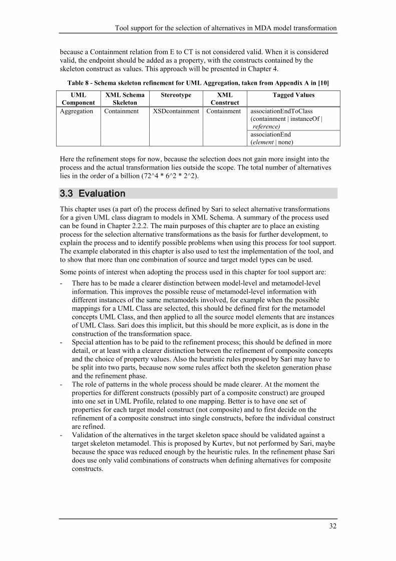
Tool support for the selection of alternatives in MDA model transformation
32
because a Containment relation from E to CT is not considered valid. When it is considered valid, the endpoint should be added as a property, with the constructs contained by the skeleton construct as values. This approach will be presented in Chapter 4.
Table 8 - Schema skeleton refinement for UML Aggregation, taken from Appendix A in [10]
UML Component
XML Schema Skeleton
Stereotype XML Construct
Tagged Values
Aggregation Containment XSDcontainment Containment associationEndToClass (containment | instanceOf | (reference) associationEnd (element | none)
Here the refinement stops for now, because the selection does not gain more insight into the process and the actual transformation lies outside the scope. The total number of alternatives lies in the order of a billion (72^4 * 6^2 * 2^2).
3.3 Evaluation This chapter uses (a part of) the process defined by Sari to select alternative transformations for a given UML class diagram to models in XML Schema. A summary of the process used can be found in Chapter 2.2.2. The main purposes of this chapter are to place an existing process for the selection alternative transformations as the basis for further development, to explain the process and to identify possible problems when using this process for tool support. The example elaborated in this chapter is also used to test the implementation of the tool, and to show that more than one combination of source and target model types can be used.
Some points of interest when adopting the process used in this chapter for tool support are: - There has to be made a clearer distinction between model-level and metamodel-level
information. This improves the possible reuse of metamodel-level information with different instances of the same metamodels involved, for example when the possible mappings for a UML Class are selected, this should be defined first for the metamodel concepts UML Class, and then applied to all the source model elements that are instances of UML Class. Sari does this implicit, but this should be more explicit, as is done in the construction of the transformation space.
- Special attention has to be paid to the refinement process; this should be defined in more detail, or at least with a clearer distinction between the refinement of composite concepts and the choice of property values. Also the heuristic rules proposed by Sari may have to be split into two parts, because now some rules affect both the skeleton generation phase and the refinement phase.
- The role of patterns in the whole process should be made clearer. At the moment the properties for different constructs (possibly part of a composite construct) are grouped into one set in UML Profile, related to one mapping. Better is to have one set of properties for each target model construct (not composite) and to first decide on the refinement of a composite construct into single constructs, before the individual construct are refined.
- Validation of the alternatives in the target skeleton space should be validated against a target skeleton metamodel. This is proposed by Kurtev, but not performed by Sari, maybe because the space was reduced enough by the heuristic rules. In the refinement phase Sari does use only valid combinations of constructs when defining alternatives for composite constructs.

Chapter 4: UML to Java transformations
33
4 UML to Java transformations This chapter discusses the generation and selection of alternative transformations from a simple source model with concepts expressed in UML to a target model in Java code. The generation of alternatives in this example is repeated three times, each time with different quality requirements imposed on the target model. Design algebra is used to represent all possible alternatives and to make selections of desired alternatives. To fulfill the quality requirements in the target model, patterns are used. Unfortunately the application of patterns conflicts with the usage of design algebra on some points. This chapter provides a possible approach to combine the usage of these two techniques. Also a format for heuristic rules is suggested, making it possible to apply the rules without additional information from the user is needed. The process describing the alternative transformation selection is defined in parallel with the elaboration of the examples in this chapter. To make the examples easier to understand, the process definition is presented before the examples. The evaluation at the end will provide a brief summary of the results and will discuss some points of improvement.
4.1 Source model The source model is a simple UML model, representing concepts and relations between concepts. Classes are used to represent the concepts in UML. The relations between concepts are represented by unidirectional associations (unidirectional indicates that the associations are only navigable on one side). The multiplicities on both endpoints of the associations are omitted from the diagram in order to underline the conceptual character of the model, but both associations should be seen as many-to-many associations (this is not the default). It is assumed that UML generalizations are available in the construction of the diagram, so using an association does imply the exclusion of a generalization. Knowing to what extent the source model is conceptual is important for the mapping process. Without this information, the mapping of the two associations to inheritance relations should also be considered, but this was not intended when creating the model.
Figure 16 – Conceptual UML model of a library
Figure 16 shows the conceptual UML model of the library used in this example. The library represents a library which contains books. On these books, operations can be performed, such as search and sort. These operations are modeled as classes, which are accessible from the library. The actual books are omitted from the example for simplicity reasons.
4.2 Target models The target models will be represented in Java code. The mapping from UML to Java within the boundaries of this example is explained for the larger part in the elaboration of the first example. The usage of quality requirements for the target model to guide the application of heuristic rules requires these quality requirements to be made explicit. Kurtev realizes this by merging quality spaces with the transformation space, which has some drawbacks. Therefore a change is proposed in the following section. Thereafter another section discusses the role of patterns and to what extend they can be integrated into the process using design algebra.

Tool support for the selection of alternatives in MDA model transformation
34
4.2.1 Quality requirements The selection of alternative target models will be performed three times, each time with different quality requirements for the target model. To keep the examples simple, at most two quality requirements are implied on the target model, but in a more real world example there would be a larger set of quality requirements. The quality requirements used in the three examples are: 1) no additional quality requirements besides the assumed ones, such as valid Java code 2) run-time adaptability with respect to the algorithms used for search and sort, e.g. linear
search, binary search, quick sort and bubble sort 3) run-time extensibility of the library with new operations, where search and sort are
examples of possible operations Tekinerdogan handles quality properties just like possible alternatives to map a concept to, such as the Object property set contains Class, Operation and Attribute, the Adaptability property set contains Fixed, Run-Time Adaptable and Compile-Time Adaptable. In this way only the desired quality properties are selected, not the target constructs that satisfies them.
Kurtev introduces a more integrated way to select and use the selected quality properties to guide the selection of alternative transformation to target models. A separate design space for each quality model is created, containing the quality properties as coordinates on each dimension. These spaces will be referred to as quality model spaces from now on. An example of a quality model is Extensibility, containing Extensible and InExtensible as quality properties. Each quality model space has the same set of dimensions as the target skeleton space. From each quality model space the desired properties are selected, at most one from each dimension. The examples in this chapter select exactly one value from each dimension, but selecting none would be also valid, if this is agreed by all the actors involved. Selecting more than one value is not possible; the coordinates must be mutually exclusive, representing possible combinations of coordinates as separate coordinates. After the desired quality properties are selected from each dimension, all spaces are merged together. This results in one target skeleton space, where the coordinates are tuples, containing one target metamodel component and zero or more quality properties. There are two drawbacks to this approach: 1. The quality properties are attached to, or combined with, the target metamodel
components, suggesting the target component satisfies these properties. But this is not the case; the target component should satisfy the quality properties.
2. When working with the target skeleton space in algebraic form, there is no visible distinction between target metamodel components and quality properties. This could be solved by using tuples instead of sets for representing the coordinates, but this always leaves room for misinterpretation.
The proposed change is to keep the quality model spaces separated, instead of merging the quality model spaces with the target skeleton space. In this way the target model components and the quality requirements are separated from each other, but can be associated together because all spaces have the same set of dimensions.
4.2.2 Patterns Design algebra projects all alternative target model elements for one source model element onto a single dimension. From these alternative target model elements, exactly one is selected in every alternative. In other words, each alternative contains one coordinate from each dimension. This one-to-one mapping of source to target model elements is inherent to design algebra. Because it is not always possible to represent source model elements using individual target model elements, or because patterns should be used to fulfill certain quality requirements for the target model, this restriction should be loosened. The approach presented in this chapter tries to accomplish this, by using composite source and target model
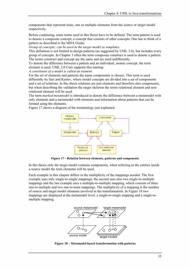
Chapter 4: UML to Java transformations
35
components that represent none, one or multiple elements from the source or target model respectively.
Before continuing, some terms used in this thesis have to be defined. The term pattern is used to denote a composite concept, a concept that consists of other concepts. One has to think of a pattern as described in the MDA Guide: Group of concepts; can be used in the target model as templates. This definition is not limited to design patterns (as suggested by UML 2.0), but includes every group of concepts. In Chapter 3 often the term composite construct is used to denote a pattern. The terms construct and concept are the same and are used indifferently. To denote the difference between a pattern and an individual, atomic concept, the term element is used. UML 2.0 Core supports this naming: A constituent of a model is called an element. For the set of elements and patterns the name components is chosen. This term is used differently by Sari and Kurtev, where model concepts are divided into a set of components and a set of relations. In this thesis relations are just elements and therefore also components, but when describing the validation the target skeleton the terms relational element and non-relational element will be used. The term marked metamodel is introduced to denote the difference between a metamodel with only elements and a metamodel with elements and information about patterns that can be formed using the elements. Figure 17 shows a diagram of the terminology just explained.
Figure 17 - Relation between elements, patterns and components
In this thesis only the target model contains components, when referring to the entities inside a source model the term elements will be used.
Each example in this chapter differs in the multiplicity of the mappings needed. The first example uses only single-to-single mappings, the second uses also two single-to-multiple mappings and the last example uses a multiple-to-multiple mapping, which consists of three one-to-multiple and two one-to-none mappings. The multiplicity of a mapping is the number of source and target model elements involved in the transformation. In Figure 18 two mappings are displayed at the metamodel level: a single-to-single mapping and a single-to-multiple mapping.
Figure 18 – Metamodel-based transformation with patterns
target models
source model
target metamodel
source metamodel

Tool support for the selection of alternatives in MDA model transformation
36
Table 9 provides an overview of the possible multiplicities of mappings that are distinguished in this report and in some cases a reference to the example in which that type of mapping is used. The distribution of the examples over the possible multiplicities does not imply a certain relation between the mappings with certain multiplicity and quality requirements used. So the lack of additional quality requirements in the first example does not mean when having only single-to-single mappings no quality requirements can be added, nor the absence of additional quality requirements means that singe-to-single mappings have to be used.
Table 9 – Possible multiplicities when mapping source to target elements
source \ target none (0)
single (1)
multiple (2+)
none (0) not useful part of 1→1+
(Sari RQ.2) 1 part of 1→2+
single (1) empty pattern element
(example 1) pattern
(example 2) multiple
(2+) multiple 1→0+ multiple 1→0+ multiple 1→0+ (example 3)
1) An example of a none-to-single mapping can be found in the thesis of Sari [22], in the application of RQ.2. This mapping can be handled easier as a single-to-multiple mapping by applying a self-made pattern to the source concept that should be extensible. This pattern then will add anyAttribute or anyElement to the target construct during the refinement phase.
One could argue if mappings with multiple source model elements should be considered as a separate type, because these mappings can be decomposed into multiple mappings having only one source model element. One reason in favor of distinguishing source model patterns is the capability of constraining the possible target skeletons in such a way that only certain patterns of source model elements can be mapped to valid target skeletons. This will be explained in more detail in this section when discussing the third example.
To make the application of patterns more concrete, along with the distinction between different types of mappings, the application of patterns in two examples presented in this chapter is discussed below. Note that the leftmost diagrams in the pictures shown below are conceptual UML class diagrams, where the other diagrams are represent Java code using UML class diagrams.
The second example in this chapter deals with run-time adaptable features. The quality model used is adaptability, containing inadaptable (InAdapt) and run-time adaptability (AdaptRT) as properties. In the left diagram in the picture below, run-time adaptability is desired for the Search and Sort features. To realize this in the target model, both concepts are mapped to a pattern that implements the strategy design pattern. Therefore Search is represented by the following elements in the target model: a Search interface, a concrete Search class, called ConcreteSearch and the (implementation) relation between these two elements. All other source model elements are mapped to single target model elements.

Chapter 4: UML to Java transformations
37
Figure 19 – Library with strategy pattern
The third example deals with the quality property of a run-time extensible set of operations. The command design pattern can be used to realize this quality property. Because there are two concepts that should be treated as a set of operations, one could see this as the mapping of a source model pattern. As mentioned above, this mapping can be decomposed into multiple mappings from single source model elements. This decomposition can be performed in multiple ways, resulting in the same target model. The decomposition can be guided by the definition of quality properties. In the example below, individual quality properties are defined for all concepts involved: Library: run-time extensible set of operations Search and Sort: operations capable of extending a run-time extensible set of operations Here there are two different quality properties, one to realize an interface for the extensible set of operations (the Command interface) and one to realize the concrete classes that implement the Command interface (the classes Search and Sort). The associations between Library and Search, and Library and Sort, are now defined by the Command interface. Additional components can be added, for example individual associations between the Library and the Search and Sort classes.
Figure 20 – Library with command pattern
Another way to decompose the pattern is to project the quality property of run-time extensible set of operations on the association relations: Library-Search and Library-Sort: run-time extensible relation to operations This will introduce two Command interfaces (along with associations and implementation relations), which should be merged in the target model, for example based on the name.
Figure 21 – Library with command pattern

Tool support for the selection of alternatives in MDA model transformation
38
The last two examples are shown to illustrate that there are multiple ways to apply patterns or to define quality properties. Many patterns are possible in combination with design algebra, even source model patterns when decomposing them, but to make the process of alternatives generation not too complex, the patterns must be kept simple.
4.3 Process definition On overview of the process used to elaborate the three examples in this chapter is depicted in Figure 22. This activity diagram is a more detailed view of the select alternative transformation activity in Figure 4. The numbers used in the headers of the examples correspond to the numbers in the activity diagrams. The selection of alternative transformation is based on the process described by Sari, which is summarized in Chapter 2.2.2 and used in Chapter 3 to transform an UML class diagram into an XML schema.
Figure 22 - Overview of the select alternative transformation process
All six activities will be explained in more detail in the rest of this section. The examples will also provide more insight in the details of the activities. Note that one can go backwards in the diagram at any time, as long as all information entered or generated after the activity where one is has gone back to, is discarded.

Chapter 4: UML to Java transformations
39
4.3.1 Activity 1 - Create target skeleton space
Figure 23 - Detailed view of activity 1: create target skeleton space
The first step in selecting alternative transformations consists of creating the target skeleton space. Most activities in this step take place at the metamodel level, so the results from these activities can be reused when creating spaces for other models, if these models are instances of the same metamodel. Activities 1.a. through 1.e. result in the data needed to create transformation spaces for source models of the same type. This data consists of the possible target metamodel components that can serve as mappings for the elements in the source metamodel. Source model elements are related to elements in the source metamodel by instance-of relations.
The list below describes each step in more detail and sometimes refers to the UML to Java transformation performed in this chapter to make things more concrete: 1.a. identify source metamodel elements
Identify UML metamodel elements like Class and Association. 1.b. identify target metamodel elements
Identify Java metamodel elements like Class, Method, Field and Interface (which are not specializations of a relationship), and Containment, Extension and Implementation (which are specialization of a relationship).
1.c. cross product metamodel elements As a starting point, all target metamodel elements are considered as valid mappings for all source metamodel elements, so to obtain all mappings the cross product of both collections can be used.
1.d. exclude impossible mappings This action is performed for each source metamodel element, for example UML Association cannot be mapped to Java Method, because a method alone cannot keep the required information between two calls.
1.e. add possible mappings using patterns

Tool support for the selection of alternatives in MDA model transformation
40
Not all source metamodel elements can be represented by a single target metamodel element, for example UML Association cannot be represented by one Java Field when the association has two navigable endpoints. Therefore patterns are introduced, which can consist of multiple elements. Most design patterns also require multiple target elements representing one source model element, which is now possible by using patterns as target metamodel components.
1.f. define source model The source model with metadata has to be defined. The metadata is used to relate the source model elements to the metamodel elements.
1.g. create dimensions with coordinates During this activity the information resulting from the previous steps is used to create the dimensions with possible coordinates for each source model element, using the instance-of relation between source model elements and metamodel elements to create the right coordinate sets for the dimensions. In other words, each dimension represents an instance of a source metamodel element in the source model and the coordinates of that dimension are the possible mappings to target metamodel components.
4.3.2 Activity 2 - Assign quality requirement
Figure 24 - Detailed view of activity 2: assign quality requirement
For every quality model that should be applied to the target model, a separate quality model space is created. This space consists of the same dimensions as the target skeleton space, but the coordinate set of each dimension contains the quality properties of the quality model. By selecting one alternative from the quality model space, one quality property for each dimension, the quality model is applied to the target model. The quality model space is not merged with the target skeleton space, as is described earlier in this chapter. 2.a. define quality model
An example of a quality model is Extensibility, containing Extensible and InExtensible as quality properties.
2.b. create quality model space The quality model space is constructed with the same dimensions as the target skeleton space, but with the quality properties from the quality model as coordinates.
2.c. select quality model alternative Select one quality property from each dimension (or zero, if this is agreed by all the actors involved in the selection process).

Chapter 4: UML to Java transformations
41
4.3.3 Activity 3 - Reduce target skeleton space
Figure 25 - Detailed view of activity 3: reduce target skeleton space
Reducing the number of alternatives contained by the target skeleton space can be performed in two ways: using metamodel concepts, independent of the source model used, or using concepts from the source model used at that time. Using metamodel concepts to query for certain instances of source metamodel elements, a set of source model elements or a set of tuples of source model elements satisfying certain conditions can be obtained. This set can be used to instantiate reduction operations, replacing undefined expressions with source model elements, so the target skeleton space can be reduced. In this way heuristic rules can be constructed that reduce target skeleton spaces from different source model that are instances of the same metamodel. The other way is to construct reductions operations that can be directly applied to the target skeleton space. The order of the operations is not important, because operations do not make use of the current status of the target skeleton space. Only when the query for source model elements also specifies certain required quality properties, these should be assigned to the model before the operations are applied. 3.a. define reduction operation template
The query part of the template, expressed using elements from the source metamodel and possible required quality properties, should return the elements from the source model that satisfy the conditions expressed in the query. The operation part should consist of a reduction operation with one or more variables, which can be replaced by the elements returned by the query, resulting in reduction operations that can be applied to the source model used at that time.
3.b. process reduction operation template This activity consists of inspecting the source model, selecting the required elements, checking whether the supplied quality properties are desired for the target model and replacing the variables in the reduction operation with the elements resulting from the query.
3.c. define reduction operation A reduction operation can be an exclude or select operation. Both operation types impose a restriction on the possible alternatives modeled by the target skeleton space.
3.b. apply reduction operation Reduce the target skeleton space by excluding or selecting certain parts expressed by the reduction operation. Exclusion comes before selection, so an excluded coordinate

Tool support for the selection of alternatives in MDA model transformation
42
cannot be the result of a selection operation, and when no coordinates are selected on a dimension, all coordinates are selected implicitly.
4.3.4 Activity 4 - Validate target skeleton space
Figure 26 - Detailed view of activity 4: validate target skeleton space
After the target skeleton space has been reduced in size, it becomes feasible to validate all alternatives on the basis of a simplified version of the target metamodel: the target skeleton metamodel. 4.a. define target skeleton metamodel
The target skeleton metamodel should define the valid relationships (specializations of the relationship element) between the other components. The metamodel should also define which elements are valid as top-level elements; elements that do not have to have relationships to other elements to be valid to exist. The target skeleton metamodel should not mark a model invalid that could be refined into a valid target model. This means that a valid target skeleton does not have to result in a valid target model (or transformation to a valid target model), because this can depend on the decisions made during the target skeleton refinement phase.
4.b. validate alternatives All alternatives that are not valid according to the target skeleton metamodel should be excluded from the target skeleton space.
4.3.5 Activity 5 - Select target skeleton alternative One of the remaining alternative target skeletons has to be chosen to be refined further, so it can be used as a specification for the transformation of the source model to a target model.
No sub-activities are defined for this activity at the moment, but in the future it may be possible to add some sort of quality value or priority value to the alternatives, so an ordered list of alternatives can be presented to the user to make the selection more orderly.

Chapter 4: UML to Java transformations
43
4.3.6 Activity 6 - Refine target skeleton alternative
Figure 27 - Detailed view of activity 6: refine target skeleton alternative
Target skeleton refinement should make the gap between the information fixed by the selected target skeleton and the information needed to transform the source model into a target model smaller or even eliminate the gap. During this activity patterns are replaces by individual elements, some of which can have alternative mappings. The relations to and from patterns should also be refined to relate to one of the elements contained within the pattern. Most elements also have various properties that can have alternative values. To implement this selection process in a systematic way, design algebra is used here once again. 6.a. create target skeleton refinement spaces
For each target element present in the selected target skeleton, one space will be created. When patterns are used, it is also that one target component will be replaced by zero, one or more than one element. Because this process is quite complex, a more detailed activity diagram is displayed below:
Figure 28 - Detailed view of activity 6.a: create target skeleton refinements spaces
6.a.I. define refinements for target metamodel elements Refinements for target metamodel elements consist of two parts: the properties and their values. Examples of such properties in the context of Java are access modifiers and the keywords abstract, static and final. The values of

Tool support for the selection of alternatives in MDA model transformation
44
the last three properties are Booleans; the access modifier property can have more than two possible values. Also a source model query can be used to obtain model specific property values.
6.a.II. exclude invalid combinations of refinement values Invalid combinations, such as mutually exclusive property values, should be excluded as early as possible.
6.a.III. define refinements for target metamodel patterns Because patterns can consist of multiple elements that do not have a separate representation in the source model, some additional information is needed to create the refinement spaces for the elements inside a pattern, such as the names for these elements. For the creation of the refinement spaces the definitions from 6.a.I. can be used.
6.a.IV. create target skeleton refinement spaces Using the definitions from the previous three activities, the refinement spaces for the selected target skeleton can be created.
6.b. reduce target skeleton refinement spaces Each space should be reduced, using information from the source model, the quality model spaces and the selected target skeleton alternative. A large part of the reduction can be performed by using default values and heuristic rules. The sub-activities correspond to the ones defined in activity 3: reduce target skeleton space.
6.c. select target skeleton refinement alternatives Finally one alternative from each refinement space should be chosen.
4.4 Example 1: library This first example will consider the transformation of the library example, expressed in a conceptual UML class diagram, to target models in Java code. Five of the six activities are passed trough, only the assignment of quality requirements is not yet considered in this first example. So first the target skeleton space is created, then this space is reduced and all remaining alternatives are validated, resulting in a feasible amount to evaluate. One target skeleton is select, which is then refined by creating refinement spaces, reducing the spaces and selecting one alternative from each space.
4.4.1 Activity 1 - Create target skeleton space Several things should be determined before the selection of alternative transformations can begin, such as the UML metamodel elements of which instances are present in the UML model, possible mappings from UML metamodel elements to Java metamodel elements and how they could be refined to specify an unambiguous transformation from UML to Java.
1.a. identify UML metamodel elements The conceptual model represented as a UML class diagram contains two UML concepts: Class and Association. In this example source model only binary, unidirectional associations are used. Binary means that an association has two endpoints and unidirectional means the associations have only one (explicit) navigable endpoint. In UML 1.5 isNavigable is a feature of AssociationEnd (which is part of an Association and specifies the connection of an Association to a Classifier), but in UML 2.0 there is no isNavigable feature [19]. The disjunction of the collections memberEnd and ownedEnd (ownedEnd is a subset of memberEnd, so the disjunction contains endpoints that are members of memberEnd, but not of ownedEnd) determines the navigable endpoints. These navigable endpoints are owned by the associated class, the other endpoints are owned by the association. This distinction between UML 1.5 and 2.0 regarding associations is important when describing queries on the source model, which is done later on in this chapter.

Chapter 4: UML to Java transformations
45
The result of this activity is a set of elements taken from the source metamodel.
Figure 29 - Selected UML metamodel elements
1.b. identify Java metamodel elements Determining which elements from the Java metamodel are suitable to act as target elements, one has to define this metamodel first. For this purpose a Java metamodel used by Kurtev is used. This metamodel is based on jnome [3] and the Java Language Specification [9]. The metamodel shows that there are four main non-relational elements: Class, Method, Field and Interface (C, M, F and I for short). One could also add abstract Class and abstract Method to this list, but according to the Java Language Specification the word abstract is a modifier for Class and Method respectively, so they are not individual components. These modifiers can be selected during the refinement phase. The name Field is used to denote the variables of a class, they should not be confused with local variables, which can be found in the body of methods. To build Java models with these four main elements, relational elements are needed to connect them together. Three relational elements are considered: Containment (Cont), Extension (Ext) and Implementation (Impl). This activity places the set of elements used from the target metamodel besides the set of elements used from the source metamodel.
Figure 30 - Selected Java metamodel elements (and UML metamodel elements)
1.c. cross product UML and Java metamodel elements For each element used from the source metamodel, a set of possible mappings in the target metamodel should be created. As a starting point, all target metamodel elements are considered to be possible mappings for all source metamodel elements. In the picture below the mapping relations are shows as solid arrows from source to target metamodel.
UML metamodel elements
Java metamodel elements
Class
Method
Field
Interface
Containment
Class
Extension
Implementation
Association
UML metamodel elements
Class
Association

Tool support for the selection of alternatives in MDA model transformation
46
Figure 31 – All mappings from UML metamodel to Java metamodel elements
1.d. exclude impossible mappings Not all mappings defined in the previous step are possible. For UML Class, the three relational target elements are impossible mappings. The remaining elements could all represent a UML Class in Java, so the set of possible mappings for UML Class consists of: Class, Method, Field and Interface. This information represented using algebraic notation: Class2Java = {C, M, F, I} (34) Associations can be represented in Java in various ways. The relational elements Extension and Implementation are excluded, because it is assumed that these two target metamodel elements should only be used when the source model indicates this explicitly. From the four non-relational elements, Interface lacks the ability to contain information about the association, so it is excluded from the possible mappings. Class, Method and Field could be good mappings, but in most cases they need additional elements to represent all information contained by the association. Because of this requirement, all three elements are excluded as possible mappings. In the next activity these three elements will form the bases for three patterns that are added to the set of possible mappings. For now only one possible mapping for UML Association remains: Association2Java = {Cont} (35) In the picture below the elements that will be represented using patterns in the next activity are displayed as dashed arrows. The solid arrows represent possible mappings; the lack of an arrow denoted an impossible mapping.
UML metamodel elements
Java metamodel elements
Class
Method
Field
Interface
Containment
Class
Extension
Implementation
Association

Chapter 4: UML to Java transformations
47
Figure 32 – Possible mappings from UML metamodel to Java metamodel elements
1.e. add possible mappings using patterns This activity will add three patterns to the set of possible mappings from UML Association to Java metamodel components. The patterns are based on Class, Method and Field respectively, which is reflected in their names: AssociationClass, AssociationMethods and AssociationFields. Because these names are quite long, most of the time AssocC, AssocM and AssocF will be used. These three patterns will be described in more detail below, from which AssocF will be described with the most detail, because this mapping will be selected in some of the examples in this chapter. The other two are also good alternatives (even better alternatives, because less information is lost during the transformation), but it would lead too far to describe them here in full extend. AssocC consists of a Java Class that holds the information of the association. The multiplicity of the endpoints can be managed by adding accessor methods to the class and navigable endpoints can be represented by Fields contained by the associated classes. When the accessor methods are directly added to the classes related by the association, no separate class is required to represent the association. This alternative mapping is called AssocM. Fields contained by the associated classes can be used to keep the information about multiplicity and navigable endpoints. In both previous mappings, Fields were used to represent the navigable endpoints. When UML Association is mapped to Field alone, one cannot always ensure the multiplicity, but because this example deals with a conceptual model, this is not really a problem. This pattern, consisting of a Java Field and Containment, is called AssocF. After these three patterns are added to the possible mappings from UML Association to Java metamodel components, the set contains four mappings: Association2Java = {Cont, AssocC, AssocM, AssocF} (36) When the patterns are added to the diagram already containing the target metamodel elements, the following figure results:
UML metamodel elements
Java metamodel elements
Class
Method
Field
Interface
Containment
Class
Extension
Implementation
Association

Tool support for the selection of alternatives in MDA model transformation
48
Figure 33 – Possible mappings from UML metamodel elements to Java metamodel components
1.f. create dimensions with coordinates The last part of the create target skeleton space activity is the creation of the dimensions that form the space. The target skeleton space in this first example will be named SLibrary1. When the space is changed, a letter is appended to the name (separated by a dot), for example SLibrary1.d denotes the fourth version (.d) of the target skeleton space used in example one (1). Space SLibrary1 is formed by creating five dimensions, each representing one of the elements from the source model. To create the dimensions in a systematical way, rules are used. The first two rules use concepts from the metamodel level to collect instances of these concepts from the source model. Then the body of the rule is applied to each collected source model concept, resulting in a dimension with coordinates. rule createDimension4Class := for all c from SourceModel where c : Class do add c to dimensions(TargetSkeletonSpace) and coordinateSet(c, TargetSkeletonSpace) = {C, M, F, I}
(37)
rule createDimension4Association: for all a from SourceModel where a : Association do add a to dimensions(TargetSkeletonSpace) and coordinateSet(a, TargetSkeletonSpace) = {Cont, AssocC, AssocM, AssocF}
(38)
The application of these rules on the source model results in a space with five dimensions: dimensions(SLibrary1) = SLibrary1 (Library, Search, Sort, Library-Search, Library-Sort)
(39) coordinateSet(Library, SLibrary1) = {C, M, F, I} (40) coordinateSet(Search, SLibrary1) = {C, M, F, I} (41) coordinateSet(Sort, SLibrary1) = {C, M, F, I} (42)
UML metamodel elements
Java metamodel elements
Class
Method
Field
Interface
Containment Class
Extension
Implementation Association
Java metamodel patterns
AssociationClass
AssociationMethods
AssociationFields

Chapter 4: UML to Java transformations
49
coordinateSet(Library-Search, SLibrary1) = {Cont, AssocC, AssocM, AssocF} (43) coordinateSet(Library-Sort, SLibrary1) = {Cont, AssocC, AssocM, AssocF} (44) Total number of alternatives, valid and invalid, can be calculated by multiplying the number of all coordinate sets: 4 * 4 * 4 * 4 * 4 = 1024. All the information gathered during this activity can be represented in a diagram. Note that the source model, displayed as a UML class diagram, should probably be serialized first before a tool can work with it. The dotted arrows, going from the UML model to the UML metamodel, represent an instance-of relationship between the model and metamodel components.
Figure 34 – Possible mappings from the UML class diagram to Java metamodel components
4.4.2 Activity 3 - Reduce target skeleton space
3.a. define reduction operation template One way to reduce the number of alternatives is to use heuristic rules that exclude or select certain parts of the space. An example of such a rule can be the local classes are not allowed in the target model. This rule is just introduced to illustrate the application of reduction operation templates; outside the scope of this example local methods could be desired constructs in target models. The rule presented below queries the source model for two associated classes, where the association should have one navigable endpoint.
UML model
UML metamodel elements
Java metamodel elements
Class
Method
Field
Interface
Containment Class
Extension
Implementation Association
Java metamodel patterns
AssociationClass
AssociationMethods
AssociationFields

Tool support for the selection of alternatives in MDA model transformation
50
rule excludeLocalMethods := for all c, c2, a from SourceModel where c, c2 : Class and a : Association and {c, c2} subset of a.memberEnd and {c2} no subset of a.ownedEnd do exclude from TargetSkeletonSpace where c = C and c2 = M and a = Cont
(45)
3.b. process reduction operation template Processing the part of the template that contains the source model query results in two tuples: {(c, c2, a)} = {(Library, Search, Library-Search), (Library, Sort, Library-Sort)} (46) The reduction operation created from the part of the template that contains the reduction operation with variables is displayed below: SLibrary1.b = exclude from SLibrary1 where Library = C and Search = M and Library-Search = Cont or Library = C and Sort = M and Library-Sort = Cont
(47)
3.d. apply reduction operation After the application of the reduction operation none of the coordinate sets of SLibrary1 are changed, but the space is reduced with two alternatives. The total number of alternatives, including invalid ones: 1024 - 2 = 1022.
3.c. define reduction operation Besides the heuristic rules expressed using metamodel concepts, one could also directly apply exclude or select operations on the target skeleton space. For the library example, such a rule could be used to compel that the classes Search and Sort are mapped to the same type of target components, because they are both features of the library in the source model. This restriction could also be applied to the associations that relate both features to the library. These two rules, represented with one selection operation, will reduce the number of alternatives in this example drastically. SLibrary1.c = select from SLibrary1.b SLibrary1.c where Search = Sort and Library-Search = Library-Sort (48)
3.d. apply reduction operation Again the result after applying the reduction operation is not visible in the coordinate sets of the dimensions, but the total number of alternatives has been reduced to 4 * 4 * 4 – 1 = 63. The last term is caused by the exclusion of local classes. The 63 remaining alternatives are shown in a compact way, using one column for the mapping of Search and Sort and one column for Library-Search and Library-Sort:
Table 10 – Library example 1, alternatives after reduction
Library Search, Sort Library-Search, Library-Sort 1-3 {C, M, F, I} {C, M, F, I} {Cont, AssocC, AssocM, AssocF}
4-15 {C, M, F, I} {C, M, F, I} {Cont, AssocC, AssocM, AssocF} 16-63 {C, M, F, I} {C, M, F, I} {Cont, AssocC, AssocM, AssocF}
Total number of alternatives, valid and invalid: 63.
4.4.3 Activity 4 - Validate target skeleton space When using design algebra to represent all possible alternatives, there should be a way to distinguish alternatives that describe transformation that result in valid instances of the target metamodel, the Java language in this example, and alternatives that cannot be refined to

Chapter 4: UML to Java transformations
51
transformation resulting in valid target models. The exclusion of invalid alternatives is called target skeleton space validation. To check whether an alternative is valid, without refinement, a simplified target metamodel should be available: the target skeleton metamodel.
4.a. define target skeleton metamodel The metamodel used in this activity must be able to validate the target skeleton space, using the source model to acquire information about relational elements, because the target skeleton components does not have any properties to represent information about relations. Because the example in this chapter only contains unidirectional associations, a single table can be used to define the valid relations between target metamodel components. The table presented here is not complete, and not all invalid target skeletons are identified, for example cyclic containment of classes or a method without a class are not marked as invalid using this table.
Table 11 – Simplified Java metamodel showing valid relations between components
From \ To Class Method Field Interface Class Cont, Ext,
AssocC, AssocM, AssocF Cont Cont Cont, Impl,
AssocC, AssocM, AssocF Method Cont - - - Field - - - - Interface Cont Cont1 Cont2 Cont, Ext
2) An Interface can contain abstract method declarations 3) An Interface can contain constants; constants are public static final fields
Table 12 – Additional information about valid relations used in Table 11
component abbreviation explanation Containment Cont from-component contains to-component Implementation Impl class implements interface Extension Ext class extends class or interface extends interface AssociationClass AssocC association mapped to Class (with methods and fields) AssociationMethods AssocM association mapped to Methods (along with fields) AssociationFields AssocF association mapped to Fields Associations from an Interface to a Class or Interface are possible in UML, but in Java there is no straightforward representation possible, because Java Interfaces cannot contain Fields to implement navigable endpoints. Therefore AssocC, AssocM and AssocF are not considered as valid relations from an Interface to a Class or Interface. A table is a compact and clear way to show the valid relations, but when the target skeleton space has to be validated by a tool, rules are more likely to be needed (or an MOF compliant metamodel with OCL). The rule below can be used, among many other rules, to select valid combinations of target skeleton components. The rule selects, or validates, classes that have one or more member classes (Class – Cont – Class from the constraint table). rule validClassToClass := for all c, c2, a from TargetSkeletonSpace, a2 from SourceModel, where c, c2 = Class and a = Cont and a2 : Association and {c, c2} subset of a2.memberEnd do select from TargetSkeletonSpace where c = Class and a = Cont and c2 = Class
(49)
4.b. validate alternatives When the current space with 63 alternatives is being validated, 49 alternatives are excluded, based on the relations defined in Table 11. The remaining fourteen alternatives are compactly shown in the following table:

Tool support for the selection of alternatives in MDA model transformation
52
Table 13 – Library example 1, alternatives after validation
Library Search, Sort Library-Search, Library-Sort 1-4 {C, I} {C, M, F, I} {Cont, AssocC, AssocM, AssocF}
5-10 {C, I} {C, M, F, I} {Cont, AssocC, AssocM, AssocF} 11-14 {C, I} {C, M, F, I} {Cont, AssocC, AssocM, AssocF}
This activity can take place everywhere between space creation and alternative selection. The most ideal place is just after the target skeleton space has been created, because then the reduction process only considers valid alternatives. But when this approach is being implemented by a tool, and the space is much larger than the ones created during the examples in this chapter, it may be way too inefficient and even impossible to perform this activity on the whole space. Therefore this activity is placed after the space has been reduced.
4.4.4 Activity 5 - Select target skeleton alternative At this point there are fourteen alternatives left to choose from. Number five is chosen to serve as the base for the rest of this example:
Table 14 – Library example 1, selected alternative
Library Search Sort Library-Search Library-Sort 5 C M M Cont Cont
This target skeleton has to be refined further before Java code can be generated, for example deciding on the access modifiers of the methods (public, protected or private) and other properties.
4.4.5 Activity 6 - Refine target skeleton alternative The result from the select target skeleton alternative activity is a singe point: (Library, Search, Sort, Library-Search, Library-Sort) = (C, M, M, Cont, Cont) (50)
6.a. create target skeleton refinement spaces The refinement phase starts with the generation of refinement spaces, one for each target model element and zero, one or more for each target model pattern in the selected alternative. For relational elements these refinement spaces will also contain information about their endpoints, which is obtained from the source model.
6.a.I. define refinements for target metamodel elements In the next three sections the possible refinements for Java Class, Containment and Method are discussed, resulting in rules to create the refinements spaces for these elements.
Class The possible modifiers for a Class are, according to the Java Language Specification [9]: ClassModifier: one of public protected private abstract static final strictfp In this chapter the modifier strictfp is not taken into account.
The creation of the dimensions and the coordinate sets are defined as a rule, where the target model element involved is supplied as an argument: rule createRefinementSpaceForClass(c) := (51)

Chapter 4: UML to Java transformations
53
do dimensions(c) = (accessMods, isStatic, isAbstract, isFinal) and coordinateSet(accessMods, c) = {public, protected, private} and coordinateSet(isStatic, c) = {true, false} and coordinateSet(isAbstract, c) = {true, false} and coordinateSet(isFinal, c) = {true, false} A simple rule to use the rule defined above, which creates a refinement space for a Java Class, to create refinement spaces for all source model elements that are mapped to a Java Class: rule addClassToTarget := for all c from TargetSkeletonSpace where c = Class do createRefinementSpaceForClass(c)
(52)
Method The possible modifiers for a Method are: MethodModifier: one of public protected private abstract static final synchronized native strictfp Representing these modifiers (besides strictfp, the modifiers synchronized and native are also omitted to make things less lengthy) in the form of a rule results in: rule createRefinementSpaceForMethod(m) := do dimensions(m) = (accessMods, isAbstract, isStatic, isFinal) and coordinateSet(accessMods, m) = {public, protected, private} and coordinateSet(isAbstract, m) = {true, false} and coordinateSet(isStatic, m) = {true, false} and coordinateSet(isFinal, m) = {true, false}
(53)
rule addMethodToTarget := for all m from TargetSkeletonSpace where m = Method do createRefinementSpaceForMethod(m)
(54)
Containment Containment means that one construct is contained within another construct. The two refinement properties that have to be decided on are the two components related to each other by the containment relation. When creating the refinement space on the metamodel level, no endpoints are known. These are added later when creating the refinement spaces for the Containment elements in the target skeleton model with the rule defined below. Because patterns reuse this rule also to create refinement spaces, the endpoints are left undefined here, so patterns can set their own endpoints when necessary. rule createRefinementSpaceForCont(c) := do dimensions(c) = (contains, containedBy) and coordinateSet(contains, c) = {} and coordinateSet(containedBy, c) = {}
(55)
The last two concepts from the source model, Library-Search and Library-Sort, are mapped to Java Containment. Because the rule which defines the refinement space does not know about possible endpoints, this is determined in this activity by querying the source model element involved. rule addContToTarget := for all c from TargetSkeletonSpace, c2 from SourceModel where c = Cont and c2 : Association and c = c2 do createRefinementSpaceForCont(c) and coordinateSet(contains, c) = {c2.memberEnd \ c2.ownedEnd} and coordinateSet(containedBy, c) = {c2.ownedEnd}
(56)

Tool support for the selection of alternatives in MDA model transformation
54
6.a.II exclude invalid combinations of refinement values
Class Invalid combinations derived from the Java Language Specification are displayed in a table:
Table 15 – Library example 1, invalid combinations class refinements
modifier restriction final, abstract mutually exclusive Transformed into a rule where a reduction operation is defined: for all c from TargetSkeletonSpace where c = Class do exclude from c where isFinal = true and isAbstract = true (57)
Method Restrictions on combinations of modifiers are:
Table 16 – Library example 1, invalid combinations method refinements
modifier restriction private, abstract mutually exclusive abstract, static mutually exclusive abstract, final mutually exclusive These restrictions can be applied on a refinement space by the definition of one rule: for all m from TargetSkeletonSpace where m = Method do exclude from m where methodAccMods = private and methodIsAbstract = true or methodIsAbstract = true and methodIsStatic = true or methodIsAbstract = true and methodIsFinal = true
(58)
Containment No invalid combinations have to be excluded here, because the coordinate sets are initially created empty.
6.a.III. define refinements for target metamodel patterns The selected target skeleton does not contain any patterns, only elements.
6.a.IV. create target skeleton refinement spaces The five refinement spaces are created by applying the rules defined above to the target model components in the selected alternative. For each target model component, first all dimensions with their coordinates are shown, then a table with all the refinement spaces is displayed.
Class The application of this rule (52) results in one refinement space for the Library concept: dimensions(SLibrary) = (accessMods, isStatic, isAbstract, isFinal) coordinateSet(accessMods, SLibrary) = {public} coordinateSet(isStatic, SLibrary) = {false} coordinateSet(isAbstract, SLibrary) = {true, false} coordinateSet(isFinal, SLibrary) = {true, false}
(59)
This space introduces a total of 3 * 2 * 2 * 2 = 24 alternative refinements for the Java Class Library. After excluding the invalid combinations of Java Class refinements defined as a separate rule above, the number of alternatives is reduced to 1 * 1 * 2 * 2 - 1 = 3:

Chapter 4: UML to Java transformations
55
Table 17 – Library example 1, refinement alternatives (after class)
Library Search Sort Library-Search Library-Sort (public, f, t, f), (public, f, f, t), (public, f, f, f)
Method The concepts Search and Sort are both mapped to Java Method, resulting in the creation of these two refinement spaces: dimensions(SSearch) = (accessMods, isAbstract, isStatic, isFinal) coordinateSet(accessMods, SSearch) = {public, protected, private} coordinateSet(isAbstract, SSearch) = {true, false} coordinateSet(isStatic, SSearch) = {true, false} coordinateSet(isFinal, SSearch) = {true, false}
(60)
dimensions(SSort) = (accessMods, isAbstract, isStatic, isFinal) coordinateSet(accessMods, SSort) = {public, protected, private} coordinateSet(isAbstract, SSort) = {true, false} coordinateSet(isStatic, SSort) = {true, false} coordinateSet(isFinal, SSprt) = {true, false}
(61)
Both spaces contain 3 * 2 * 2 * 2 – 10 = 14 alternatives:
Table 18 – Library example 1, refinement alternatives (after method)
Library Search Sort Library-Search Library-Sort
(public,f,t,f), (public,f,f,t), (public,f,f,f)
(public,t,f,f), (public,f,t,t), (public,f,f,t), (public,f,t,f), (public,f,f,f),
(protected,t,f,f), (protected,f,t,t), (protected,f,f,t), (protected,f,t,f), (protected,f,f,f) (private,f,t,t), (private,f,f,t), (private,f,t,f), (private,f,f,f)
(public,t,f,f), (public,f,t,t), (public,f,f,t), (public,f,t,f), (public,f,f,f),
(protected,t,f,f), (protected,f,t,t), (protected,f,f,t), (protected,f,t,f), (protected,f,f,f) (private,f,t,t), (private,f,f,t), (private,f,t,f), (private,f,f,f)
The total number of alternative target model transformations can be calculated by multiplying the number of alternatives of all refinement spaces: 3 * 14 * 14 = 588.
Containment The two instantiated refinement spaces for the Containment components (56): dimensions(SLibrary-Search) = (contains, containedBy) coordinateSet(contains, SLibrary-Search) = {Search} coordinateSet(containedBy, SLibrary-Search) = {Library}
(62)
dimensions(SLibrary-Sort) = (contains, containedBy) coordinateSet(contains, SLibrary-Sort) = {Sort} coordinateSet(containedBy, SLibrary-Sort) = {Library}
(63)
Both spaces contain only one point, so the total number of alternatives is not increased:

Tool support for the selection of alternatives in MDA model transformation
56
Table 19 – Library example 1, refinement alternatives (after containment)
Library Search Sort Library-Search Library-Sort
(public,f,t,f), (public,f,f,t), (public,f,f,f)
(public,t,f,f), (public,f,t,t), (public,f,f,t), (public,f,t,f), (public,f,f,f),
(protected,t,f,f), (protected,f,t,t), (protected,f,f,t), (protected,f,t,f), (protected,f,f,f) (private,f,t,t), (private,f,f,t), (private,f,t,f), (private,f,f,f)
(public,t,f,f), (public,f,t,t), (public,f,f,t), (public,f,t,f), (public,f,f,f),
(protected,t,f,f), (protected,f,t,t), (protected,f,f,t), (protected,f,t,f), (protected,f,f,f) (private,f,t,t), (private,f,f,t), (private,f,t,f), (private,f,f,f)
(Search,Library) (Sort,Library)
The total number of alternatives is still 588.
6.b. reduce target skeleton refinement spaces Just like when reducing the target skeleton space, the refinement space can be reduced by applying heuristic rules, or default values can be defined for most of the properties. Also invalid combinations of refined target elements can be defined and excluded from the space, but maybe this should placed in a separated activity like the validate target skeleton space in the first phase of alternatives generation, or this should not be supported by the alternative transformation selection tool, but by an external process, such as a compiler in the case of Java code as target models.
6.c. select target skeleton refinement alternatives From the 588 alternative transformations, one alternative is chosen to be used as the transformation definition (or as input for a transformation definition) to transform the conceptual UML class diagram into Java code:
Table 20 – Library example 1, selected refinements
Library Search Sort Library-Search Library-Sort (public,f,f,f) (public,f,f,f) (public,f,f,f) (Search,Library) (Sort,Library)
And finally the transformation to Java code can be performed, ultimately by a tool, but for the moment by hand. The return value of methods could also be determined during the refinement phase, but in this case no return value is known, so void is used. public class Library { public void search() { } public void sort() { } }

Chapter 4: UML to Java transformations
57
Figure 35 – Possible mappings from the UML source model to Java elements and composites
From this section it becomes clear that a tool would be a very nice aid for modeling and selecting alternative transformations.
4.5 Example 2: library with run-time adaptable algorithms This example differs from the first one by requiring that the target model does contain a certain quality property: run-time adaptability with respect to the algorithms used for search and sort, for example linear search, binary search, quick sort and bubble sort. To realize that the concepts search and sort are run-time adaptable in the target space, the strategy design pattern [7] can be used to structure the Java code. The UML model on the left side of Figure 36 shows a class and a related feature. The right UML model shows the concepts from the left model after the Strategy pattern has been applied. Because the class communicates via an interface with the concrete feature, the concrete feature can be replaced at run-time by another implementation of the interface Feature.
UML model
UML metamodel elements
Java metamodel elements
Class
Method
Field
Interface
Containment Class
Extension
Implementation Association
Java metamodel composites
AssociationClass
AssociationMethods
AssociationFields
Java model Java model
Java model
pulbic class Library { public void search() {} public void sort() {} }

Tool support for the selection of alternatives in MDA model transformation
58
Figure 36 – Two UML class diagrams, before and after the strategy pattern has been applied
One could argue about to what extend the pattern should be outlined in the target model. When the source model elements Search and Sort are mapped to a Java Interface, without their concrete classes, this could be enough to satisfy the target model requirements. But because the concrete classes could be endpoints of associations existing in the source model, these concrete classes should also be added to the target model. No methods are added to the strategy interface and the concrete classes, but this could be possible when desired.
4.5.1 Activity 1 - Create target skeleton space Only the activities that are different from the first activity in the previous example are shown.
1.e. add possible mappings using patterns To be able to realize the quality requirements, a new pattern is added to the target metamodel: PatternStrategy (in algebra the name PStrategy will be used). Class2Java = {C, M, F, I, PStrategy} (64) This pattern consists of three target metamodel components: an Interface, a Class and in Implementation relation that relates the Class to the Interface. The corresponding Java code using Feature as the concept that should be run-time adaptable is shown below: interface Strategy { } class ConcreteStrategy implements Strategy { }

Chapter 4: UML to Java transformations
59
Figure 37 – Possible mappings from UML metamodel elements to Java metamodel components
1.f. create dimensions with coordinates The new pattern is added as a possible mapping for UML Class, so the rule that creates the dimensions for all instances of UML Class in the source model is altered: rule createDimension4Class := for all c from SourceModel where c : Class do add c to dimensions(TargetSkeletonSpace) and coordinateSet(c, TargetSkeletonSpace) = {C, M, F, I, PStrategy}
(65)
The space created with this new rule is slightly different from the space created in the previous example: dimensions(SLibrary2) = SLibrary1 (Library, Search, Sort, Library-Search, Library-Sort)
(66) coordinateSet(Library, SLibrary2) = {C, M, F, I, PStrategy} (67) coordinateSet(Search, SLibrary2) = {C, M, F, I, PStrategy} (68) coordinateSet(Sort, SLibrary2) = {C, M, F, I, PStrategy} (69) coordinateSet(Library-Search, SLibrary2) = {Cont, AssocC, AssocM, AssocF} (70) coordinateSet(Library-Sort, SLibrary2) = {Cont, AssocC, AssocM, AssocF} (71) Although only one coordinate is added to three dimensions, the number of alternatives is almost doubled. Now there are 5 * 5 * 5 * 4 * 4 = 2000 valid and invalid alternatives.
UML metamodel concepts
Java metamodel concepts
Class
Method
Field
Interface
Containment
Class Extension
Implementation Association
Java metamodel composite constructs
AssociationClass
AssociationMethods
AssociationFields
PatternStrategy

Tool support for the selection of alternatives in MDA model transformation
60
4.5.2 Activity 3 - Reduce target skeleton space To reduce the amount of alternatives, heuristic rule (48) from the previous example is used here also. This rule compels the same mappings for Search and Sort and for Library-Search and Library-Sort. The rule reduces the space to 5 x 5 x 4 = 100 alternatives.
4.5.3 Activity 2 - Assign quality requirement New in this example is the assignment of quality requirements to the target model.
2.a. define quality model The quality model space which will be created in the next step is based on a quality model. Each dimension of this space consists of the quality properties from the quality model. An example of such a quality model is adaptability, containing inadaptable (InAdapt) and run-time adaptability (AdaptRT) as properties. There could be other kinds of adaptability present in the model, but for this example these two are sufficient.
2.b. create quality model space The quality model space contains the same dimensions as the target skeleton space. The two quality properties defined in the previous step are added to each dimension, resulting in a quality model space defining adaptability properties for SLibrary2: dimensions(SLibrary2Adapt) = SLibrary2Adapt {Library, Search, Sort, Library-Search, Library-Sort}
(72) coordinateSet(Library, SLibrary2Adapt) = {InAdapt,AdaptRT} (73) coordinateSet(Search, SLibrary2Adapt) = {InAdapt,AdaptRT} (74) coordinateSet(Sort, SLibrary2Adapt) = {InAdapt,AdaptRT} (75) coordinateSet(Library-Search, SLibrary2Adapt) = {InAdapt,AdaptRT} (76) coordinateSet(Library-Sort, SLibrary2Adapt) = {InAdapt,AdaptRT} (77)
23.c. select quality model alternative From this space, only one alternative should be selected. Because the concepts Search and Sort should be run-time adaptable, AdaptRT is selected from these dimensions. From the remaining dimensions InAdapt is selected. SLibrary2Adapt.b = select from SLibrary2Adapt SLibrary2Adapt.b where Library.InAdapt SLibrary2Adapt.b and Search.AdaptRT SLibrary2Adapt.b and Sort.AdaptRT SLibrary2Adapt.b and Library-Search.InAdapt SLibrary2Adapt.b and Library-Sort.InAdapt
(78)
4.5.4 Activity 3 - Reduce target skeleton space (2) From this point on, heuristic rules can make use of selected alternatives in quality model spaces to determine if mappings that realize certain quality properties should be selected.
3.a. define reduction operation template An example of such a rule that realizes a quality property is displayed below. Here the quality property is run-time adaptability and this is realized by mapping a UML Class to Java components according to the strategy design pattern. for all c from SourceModel, a from AdaptabilitySpace where c : Class and a = AdaptRT and c = a do select from TargetSkeletonSpace where c = PStrategy
(79)
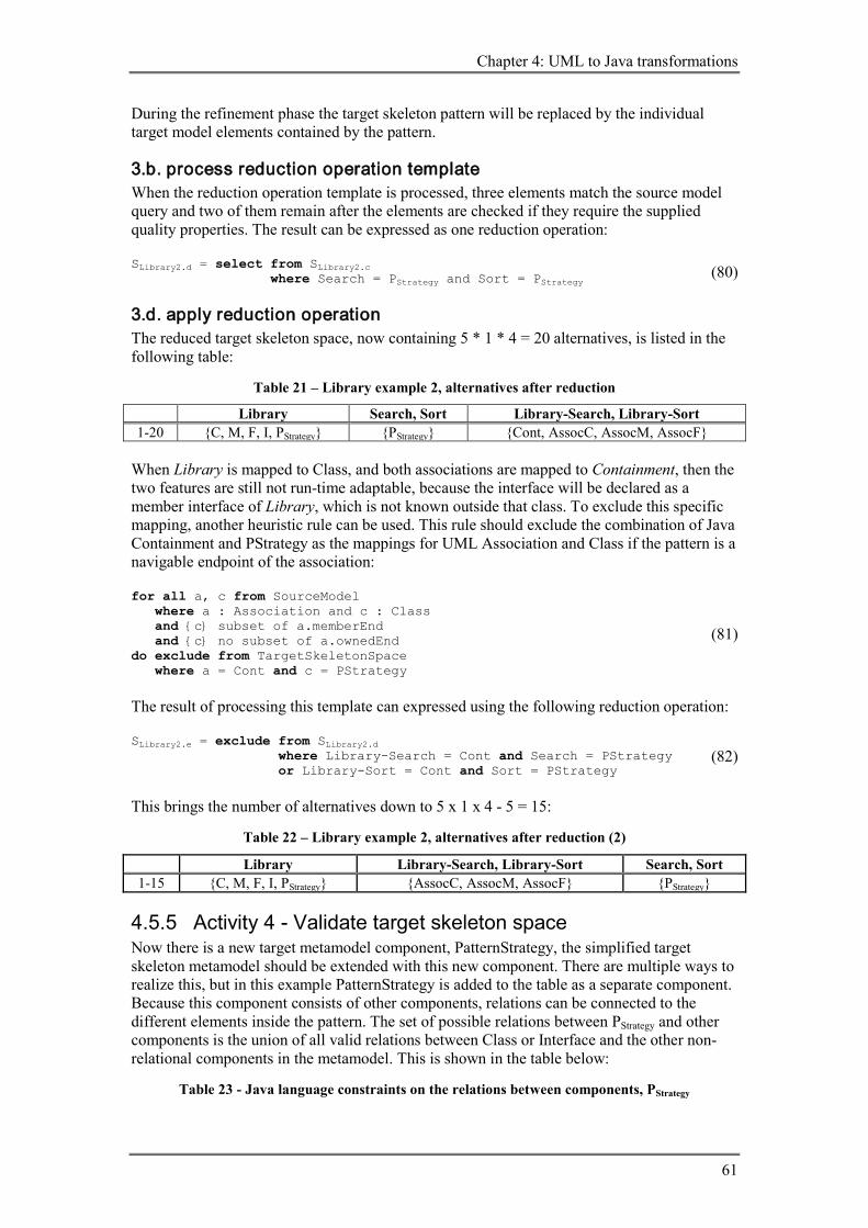
Chapter 4: UML to Java transformations
61
During the refinement phase the target skeleton pattern will be replaced by the individual target model elements contained by the pattern.
3.b. process reduction operation template When the reduction operation template is processed, three elements match the source model query and two of them remain after the elements are checked if they require the supplied quality properties. The result can be expressed as one reduction operation: SLibrary2.d = select from SLibrary2.c SLibrary2.d where Search = PStrategy and Sort = PStrategy (80)
3.d. apply reduction operation The reduced target skeleton space, now containing 5 * 1 * 4 = 20 alternatives, is listed in the following table:
Table 21 – Library example 2, alternatives after reduction
Library Search, Sort Library-Search, Library-Sort 1-20 {C, M, F, I, PStrategy} {PStrategy} {Cont, AssocC, AssocM, AssocF}
When Library is mapped to Class, and both associations are mapped to Containment, then the two features are still not run-time adaptable, because the interface will be declared as a member interface of Library, which is not known outside that class. To exclude this specific mapping, another heuristic rule can be used. This rule should exclude the combination of Java Containment and PStrategy as the mappings for UML Association and Class if the pattern is a navigable endpoint of the association: for all a, c from SourceModel where a : Association and c : Class and {c} subset of a.memberEnd and {c} no subset of a.ownedEnd do exclude from TargetSkeletonSpace where a = Cont and c = PStrategy
(81)
The result of processing this template can expressed using the following reduction operation: SLibrary2.e = exclude from SLibrary2.d SLibrary2.e where Library-Search = Cont and Search = PStrategy SLibrary2.e or Library-Sort = Cont and Sort = PStrategy
(82)
This brings the number of alternatives down to 5 x 1 x 4 - 5 = 15:
Table 22 – Library example 2, alternatives after reduction (2)
Library Library-Search, Library-Sort Search, Sort 1-15 {C, M, F, I, PStrategy} {AssocC, AssocM, AssocF} {PStrategy}
4.5.5 Activity 4 - Validate target skeleton space Now there is a new target metamodel component, PatternStrategy, the simplified target skeleton metamodel should be extended with this new component. There are multiple ways to realize this, but in this example PatternStrategy is added to the table as a separate component. Because this component consists of other components, relations can be connected to the different elements inside the pattern. The set of possible relations between PStrategy and other components is the union of all valid relations between Class or Interface and the other non-relational components in the metamodel. This is shown in the table below:
Table 23 - Java language constraints on the relations between components, PStrategy

Tool support for the selection of alternatives in MDA model transformation
62
From \ To Class Method Field Interface PStrategy Class Cont, Ext,
Assoc{C, M, F} Cont Cont Cont, Impl,
Assoc{C, M, F} Cont, Impl,
Assoc{C, M, F} Method Cont - - - Cont Field - - - - - Interface Cont Cont1 Cont2 Cont, Ext Cont, Ext PStrategy Cont, Ext,
Assoc{C, M, F} Cont Cont Cont, Impl, Ext,
Assoc{C, M, F} Cont, Impl, Ext, Assoc{C, M, F}
1) An Interface can contain abstract method declarations 2) An Interface can contain constants; constants are public static final fields
Because PStrategy consists of multiple elements, associations with this component as an endpoint must be altered to have one of the contained elements as an endpoint, instead of the whole composite component. This decision is postponed to the refinement phase, but during the current phase one has to select a mapping for the associations, which can limit the possible choices for endpoints during refinement. When using the updated table to check the validity of alternatives, six alternatives remain:
Table 24 – Library example 2, alternatives after validation
Library Search, Sort Library-Search, Library-Sort 1-6 {C, PStrategy} {PStrategy} {AssocC, AssocM, AssocF}
Total number of alternatives is 2 * 1 * 3 = 6.
4.5.6 Activity 5 - Select target skeleton alternative Because the refinement for AssocF is already worked out, and mapping Library to PatternStrategy is not necessary, the third alternative is selected:
Table 25 – Library example 2, selected alternative
Library Search Sort Library-Search Library-Sort 3 C Pstrategy Pstrategy AssocF AssocF
4.5.7 Activity 6 - Refine target skeleton alternative The result from the target skeleton selection is a point: (Library, Search, Sort, Library-Search, Library-Sort) = (C, PStrategy, PStrategy, AssocF, AssocF)
(83) Some possible refinement properties for Class, Containment and Method were discussed in the previous example. In this example three new Java components are introduced during the refinement phase: Interface, Implementation and Field. Both Interface and Implementation are part of PatternStrategy; Field is part of AssocF.
6.a. create target skeleton refinement spaces The refinement spaces for Interface, Implementation and Field will be defined here.
6.a.I. define refinements for target metamodel elements
Interface The available modifiers for an Interface are listed in the Java Language Specification [9]. InterfaceModifier: one of

Chapter 4: UML to Java transformations
63
public protected private abstract static strictfp Besides strictfp, the modifier abstract is also omitted, because it is deprecated.
Creation rules for the refinement space of an Interface: rule createRefinementSpaceForInterface(i) =: do dimensions(i) = (accessMods, isStatic) and coordinateSet(accessMods, i) = {public, protected, private} and coordinateSet(isStatic, i) = {true, false}
(84)
rule addInterface2Refinements: for all i from TargetSkeletonSpace where i = Interface do createRefinementSpaceForInterface(i)
(85)
Implementation Because implementation indicates a relation between two or more classes, there are two sets of endpoints that may need to be refined. Because the endpoints are determined when creating the spaces, the coordinate sets are created empty: rule createRefinementSpaceForImpl(i) := do dimensions(i) = (supplier, client) and coordinateSet(supplier, i) = {} and coordinateSet(client, i) = {}
(86)
rule addImplementation2Refinements: for all i from TargetSkeletonSpace where i = Implementation do createRefinementSpaceForImplementation (i)
(87)
Field The modifiers for Field are: FieldModifier: one of public protected private static final transient volatile To know to what type of object the field is referencing, an extra dimension is added: type. When more than one instance should be referenced by the field, an array or some collection will be the actual type of the field. In the refinement space this type can be chosen as a value of the refinement property collectionType. When only one instance should be referenced, the value object should be chosen. rule createRefinementSpaceForField(f) := do dimensions(f) = (accessMods, isStatic, isFinal, isTransient, isVolative, type, containedType) and coordinateSet(accessMods, f) = {public, protected, private} and coordinateSet(isStatic, f) = {true, false} and coordinateSet(isFinal, f) = {true, false} and coordinateSet(isTransient, f) = {true, false} and coordinateSet(isVolatile, f) = {true, false} and coordinateSet(type, f) = {} and coordinateSet(collectionType, f) = {object, array, collection}
(88)
rule addField2Refinements: for all f from TargetSkeletonSpace where f = Field do createRefinementSpaceForField (f)
(89)
6.a.II. exclude invalid combinations of refinement values
Interface

Tool support for the selection of alternatives in MDA model transformation
64
No invalid combinations exist in the refinement space.
Implementation No invalid combinations have to be excluded here, because the coordinate sets are initially created empty.
Field Invalid combinations of the modifiers for Field:
Table 26 – Library example 2, invalid combinations field refinements
Modifier restriction final, volatile mutually exclusive Excluding the invalid combinations from the refinement space: for all f from TargetSkeletonSpace where f = Field do exclude from f where isFinal = true and isVolatile = true (90)
6.a.III. define refinements for target metamodel patterns All elements needed during this refinement phase, including the elements that are contained by patterns, are examined. Now the patterns present in the selected target skeleton should be replaced by individual elements first. When creating refinement spaces for relational constructs like AssocF, the elements contained by other composite components should be known, because they should be available as possible endpoints. The names non-relational elements of which a component exists are added to the environment as facts by rules expressed at the metamodel level: rule AssocF2Elements := for all a from TargetSkeletonSpace where a = AssocF do elements(a, "contains" + a)
(91)
rule PStrategy2Elements := for all p from TargetSkeletonSpace where p = PStrategy do elements(p) = {p, "Concrete" + p, "implements" + p}
(92)
Applied to the selected coordinate: (Library, Search, Sort, Library-Search, Library-Sort) = (C, PStrategy, PStrategy ,AssocF, AssocF)
(93) elements(Library) = {Library} (94) elements(Search) = {Search, ConcreteSearch, implementsSearch} (95) elements(Sort) = {Sort, ConcreteSort, implementsSort} (96) elements(Library-Search) = {Library-Search, containsLibrary-Search} (97) elements(Library-Sort) = {Library-Sort, containsLibrary-Sort} (98)
AssocF rule addAssocF2Target := for all a from TargetSkeletonSpace, a2 from Source where a = AssocF and a = a2 and a2 : Association
(99)

Chapter 4: UML to Java transformations
65
do createRefinementSpaceForCont("contains" + a) and createRefinementSpaceForField(a) and coordinateSet(type, a) = collect elements(c) from a2.memberEnd \ a2.ownedEnd
PStrategy rule addPStrategy2Target := for all p from TargetSkeletonSpace, p2 from Source where p = PStrategy and p = p2 and p2 : Class do createRefinementSpaceForInterface(p) and createRefinementSpaceForClas("Concrete" + p) and createRefinementSpaceForImpl("implements" + p) and coordinateSet(supplier, "implements" + p) = {p} and coordinateSet(client, "implements" + p) = {"Concrete" + p}
(100)
6.a.IV. create target skeleton refinement spaces Now that the all elements are known (non-relational and only by name), the order in which the rules for refinement space creation are applied does not matter anymore. To represent the space, the table below is used. Because Search and Sort and their associations are mapped to the same components, only Search an its association are shown in the table, to save space. The refinement for Library is the same as in the previous example, so these alternatives are already included in the table: Library Search ConcreteSearch implements
Search contains Library-Search
Library-Search
{(public,f,t,f), (public,f,f,t), (public,f,f,f)}
Next the AssocF component will be added to the target model, introducing two refinement spaces, one for the Field and another for the Containment relation. Note that the set of elements is used here to gather all possible containedTypes.
AssocF (99) AssocF – Containment: dimensions(ScontainsLibrary-Search) = {contains, containedBy} (101) coordinateSet(contains, ScontainsLibrary-Search) = {Library-Search} (102) coordinateSet(containedBy, ScontainsLibrary-Search) = {Library} (103) AssocF – Field: dimensions(SLibrarySearch) = (accessMods, isStatic, isFinal, isTransient, isVolative, type, containedType) (104) coordinateSet(accessMods, SLibrarySearch) = {public, protected, private} (105) coordinateSet(isStatic, SLibrarySearch) = {true, false} (106) coordinateSet(isFinal, SLibrarySearch) = {true, false} (107) coordinateSet(isTransient, SLibrarySearch) = {true, false} (108)

Tool support for the selection of alternatives in MDA model transformation
66
coordinateSet(isVolative, SLibrarySearch) = {true, false} (109) coordinateSet(type, SLibrarySearch) = {Search, ConcreteSearch, Search[], ConcreteSearch[], Collection} (110)
PStrategy (100)
PStrategy – Interface (Search) dimensions(SSearch) = {accessMods, isStatic} (111) coordinateSet(accessMods, SSearch) = {public} (112) coordinateSet(isStatic, SSearch) = {false} (113)
PStrategy – Implementation (implementsSearch) dimensions(SimplementsSearch) = {supplier, client} (114) coordinateSet(supplier, SimplementsSearch) = {Search} (115) coordinateSet(client, SimplementsSearch) = {ConcreteSearch} (116)
PStrategy – Class (ConcreteSearch) dimensions(SLibrary) = (accessMods, isStatic, isAbstract, isFinal) coordinateSet(accessMods, SLibrary) = {public} coordinateSet(isStatic, SLibrary) = {false} coordinateSet(isAbstract, SLibrary) = {true, false} coordinateSet(isFinal, SLibrary) = {true, false}
(117)
Library Search implements
Search Conc.Search contains Library-Search Library-Search
{(pub,f,t,f), (pub,f,f,t), (pub,f,f,f)}
{(pub,f)} {(Search, Conc.Search)}
{(pub,f,t,f), (pub,f,f,t), (pub,f,f,f)}
{(Library-Search, Library)}
{(pub,t,t,t,t,Search), (pub,t,t,t,t,Conc.Srch), …another 178 alts.}
Number of alternatives is 3 x 1 x 180 x 1 x 1 x 3 = 1620. In a real world example this number is much larger, because the possible types of a field is about 20 or more property values instead of the 5 considered here.
modifier restriction public, protected, private mutually exclusive static only valid for member interfaces Static should only be a possible property for member interfaces: for all i, r, c from TargetSkeletonSpace, r2 from Target where i = Interface and not (r = Containment and r = r2 and {i, c} subset of r2.memberEnd and (c = Class or c = Interface) and {c} no subset of r2.ownedEnd) do exclude from c where isStatic = true
(118)
The application of this rule on the selected coordinate is postponed to the end of this section, because first composite constructs must be replaced by individual concepts.

Chapter 4: UML to Java transformations
67
4.6 Example 3: library with run-time extensible operations The target model should satisfy the following quality property: run-time extensibility of the library with new operations, where search and sort are examples of possible operations. There are multiple ways to add these requirements to components in the source model. Because Library should be extensible with new operations, and Search and Sort are examples of such extensional operations, the pattern can be considered as two separate parts. One where the Library is made suitable to be extended with new operations and one in which Search (and Sort) are altered to be able to serve as extensions to Library. So the target model should fulfill two different quality requirements: Library should be run-time extensible with new operations, and Search and Sort should be able to serve as run-time extensions to Library. Other approaches are possible, e.g. the associations between Library and Search and between Library and Sort could be marked as a run-time extension relations of the related classes and mapped to components containing an Interface. These interfaces then could be merged during the refinement phase, which is possible if they have the same name.
Figure 38 – Two UML class diagrams, before and after the command pattern has been applied
We take the same shortcut as in the previous example by skipping unchanged activities.
4.6.1 1. create target skeleton space
1.e. add possible mappings using patterns As mentioned before, there are multiple ways to apply this pattern on the source elements. In this example all source model elements are mapped to a certain part of the command pattern. This introduces three new composite components to the target metamodel space: PatternCommandClient, PatternCommandSupplier and PatternCommandLink. PatternCommandClient consists of Class and an associated Interface. The interface represents the Command interface in the command pattern, which is represented in Java code as this code fragment (optional methods are omitted): interface Command { } The association relations is not fixed in this pattern, but can be chosen in the refinement phase. PatternCommandSupplier consists of a Class and an Implementation relation, where Command is implemented by the concrete class. The corresponding Java code is shown below: class ConcreteCommand implements Command

Tool support for the selection of alternatives in MDA model transformation
68
{ } PatternCommandLink is a target component representing the associations between a target PatternCommandSupplier and PatternCommandClient. Because the Command interface is a uniform type, no separate association are needed to associate the concrete Search and Sort classes with the Library. So the mappings of the two associations can be omitted from the target model. Other mappings are also possible, but not without changing the portioning of the pattern.
1.f. create dimensions The three components introduced in the previous section should be added to the rules which add a dimension for each source element: rule addClass := for all c from SourceModel where c : Class do add c to dimensions(TargetSkeletonSpace) and coordinateSet(c, TargetSkeletonSpace) = {C, M, F, I, PCmdClient, PCmdSupplier)
(119)
rule addAssociation := for all a from SourceModel where a : Association do add a to dimensions(TargetSkeletonSpace) and coordinateSet(a, TargetSkeletonSpace) = {Cont, AssocC, AssocM, AssocF, PCmdLink)
(120)
The space created with these altered rules is shown below:
UML metamodel concepts
Java metamodel concepts
Class
Method
Field
Interface
Containment
Class
Extension
Implementation
Association Java metamodel composite constructs
AssociationClass
AssociationMethods
AssociationFields
PatternCommandClient
PatternCommandSupplier
PatternCommandLink

Chapter 4: UML to Java transformations
69
dimensions(SLibrary3) = SLibrary1 (Library, Search, Sort, Library-Search, Library-Sort)
(121) coordinateSet(Library, SLibrary3) = {C, M, F, I, PCmdClient, PCmdSupplier} (122) coordinateSet(Search, SLibrary3) = {C, M, F, I, PCmdClient, PCmdSupplier} (123) coordinateSet(Sort, SLibrary3) = {C, M, F, I, PCmdClient, PCmdSupplier} (124) coordinateSet(Library-Search, SLibrary3) = SLibrary3 {Cont, AssocC, AssocM, AssocF, PCmdLink}
(125) coordinateSet(Library-Sort, SLibrary3) = SLibrary3 {Cont, AssocC, AssocM, AssocF, PCmdLink}
(126) The total number of alternatives starting with is: 6 x 5 x 5 x 6 x 6 = 5400.
4.6.2 2. reduce target skeleton space To limit the amount of possible coordinates, again heuristic rule (48) is applied in this example to compel the same mappings for Library-Search and Library-Sort and for Search and Sort. This reduces the space to 6 x 5 x 6 = 180 alternatives.
4.6.3 3. assign quality requirements In this example a new approach
3.a. define quality model In the introduction of this example, two different quality requirements were mentioned: run-time extensible set of operations and run-time extension operations. For these requirements two quality models are created: Extensibility (Ext) and Reusability (Reuse). The possible values for Extensibility are limited to this example only: inextensible set of operations (InExtOps) and run-time extensible set of operations (ExtOpsRT). Reusability contains two values related to the properties of the previous quality model: no extension operation (NoExtnOp) and run-time extension operation (ExtnOpRT). quality model quality properties
Extensibility (Ext) inextensible run-time extensible set of operations
(InExt) (ExtOpsRT)
Reusability (Reuse) not reusable run-time reusable operation
(NoReuse) (ReuseOpRT)
3.b. create quality model space Two quality spaces are created based on the two quality model. These spaces are not included in this report, only the selected coordinates are shown in the next section.
3.c. select quality model alternative From each of the two spaces, one alternative is selected, representing the desired quality property for each dimension. SLibrary3Ext.b = select from SLibrary3Ext SLibrary2Adapt.b where Library = ExtOpsRT SLibrary2Adapt.b and Library-Search = InExt SLibrary2Adapt.b and Library-Sort = InExt SLibrary2Adapt.b and Search = InExt SLibrary2Adapt.b and Sort = InExt
(127)

Tool support for the selection of alternatives in MDA model transformation
70
SLibrary3Reuse.b = select from SLibrary3Reuse SLibrary2Adapt.b where Library = NoReuse SLibrary2Adapt.b and Library-Search = NoReuse SLibrary2Adapt.b and Library-Sort = NoReuse SLibrary2Adapt.b and Search = ReuseOpRT SLibrary2Adapt.b and Sort = ReuseOpRT
(128)
Instead of merging the spaces, the quality properties are added as facts to the dimensions of the transformation space: coordinateSet(Library, extensibility) = {ExtOpsRT, NoReuse} (129) coordinateSet(Search, SLibrary3.c) = {InExt, ReuseOpRT} (130) coordinateSet(Sort, SLibrary3.c) = {InExt, ReuseOpRT} (131) coordinateSet(Library-Sort, SLibrary3.c) = {InExt, NoReuse} (132) coordinateSet(Library-Search, SLibrary3.c) = {InExt, NoReuse} (133)
4.6.4 3. reduce target skeleton space (using quality properties)
3.a. define reduction operation template From this point on, heuristic rules can be used to guide the selection process based on the quality requirements stated in the transformation space. An example of such a rule is: for all c from TargetSkeletonSpace, c2 from SourceModel, c3 from ExtensibilitySpace where c2 : Class and c3 {ExtOpsRT} subset of qualityRequirements(c) do select from TargetSkeletonSpace where c = PCmdClient
(134)
for all c from TargetSkeletonSpace, c2 from SourceModel where c2 : Class and {ReuseOpRT} subset of qualityRequirements(c) do select from TargetSkeletonSpace where c = PCmdSupplier
(135)
Applying the two heuristic rules to SLibrary2.c results in a concrete rule: SLibrary2.d = select from SLibrary2.c SLibrary2.d where Library = PCmdClient SLibrary2.d and Search = PCmdSupplier and Sort = PCmdSupplier
(136)
Because the relation between de Library and the Search and Sort classes is now denoted by the relation between the Library and the Command interface, the two associations from the source model are not required in the target model. Therefore the relations between a Class mapped to PCmdClient and Class mapped to PCmdSupplier should be mapped to a special component: PCmdLink. This component is mapped to nothing in the refinement phase. for all c1,a,c3 from TargetSkeletonSpace, c2,a2,c4 from SourceModel where c3 : Class and c1 = ExtOpsRT and c4 : Class and c2 = ReuseOpRT and a2 : Association and {c,c2} subset of a2.memberEnd and {c} subset of a2.ownedEnd do select from TargetSkeletonSpace where a = PCmdLink
(137)
Using this heuristic rule results in a space with only one alternative: Library Search, Sort Library-Search,

Chapter 4: UML to Java transformations
71
Library-Sort 1-20 {PCmdClient} {PCmdSupplier} {PCmdLink}
4.6.5 4. validate space Table 27 - Java language constraints on the relations between components,
including PCmdClient, PCmdSupplier and PCmdLink
From \ To Class M F Interface PCmdClient PCmdSupplier Class Cont, Ext,
Assoc{C, M, F} Cont Cont Cont, Impl,
Assoc{C, M, F} Cont, Impl, Ext, Assoc{C, M, F}
Cont, Impl, Ext, Assoc{C, M, F}
Method Cont - - - Cont Cont Field - - - - - - Interface Cont Cont
1 Cont2
Cont, Ext Cont, Ext Cont, Ext
PCmdClient Cont, Ext, Assoc{C, M, F}
Cont Cont Cont, Impl, Ext, Assoc{C, M, F}
Cont, Impl, Ext, Assoc{C, M, F}
Cont, Impl, Ext, Assoc{C, M, F}, PcmdLink
PCmdSupplier Cont, Ext, Assoc{C, M, F}
Cont Cont Cont, Impl, Ext, Assoc{C, M, F}
Cont, Impl, Ext, Assoc{C, M, F}
Cont, Impl, Ext, Assoc{C, M, F}
1) For related footnotes, see Table 11.
4.6.6 5. select coordinate
4.6.7 6. refinement The result from alternatives selection can be represented by a single coordinate: (Library, Search, Sort, Library-Search, Library-Sort) = (PCmdClient, PCmdSupplier, PCmdSupplier, PCmdLink, PCmdLink)
(138) All possible refinement aspects for Java elements were discussed in the previous two examples. However, in this example three new Java components are used: PCmdClient, PCmdSupplier and PCmdLink.
6.a. create refinement spaces
6.a.III. define refinements for target metamodel patterns rule PCmdClient2Elements := for all p from TargetSkeletonSpace where p = PCmdClient do elements(p) = {p, "Command"}
(139)
rule PCmdSupplier2Elements := for all p from TargetSkeletonSpace where p = PCmdSupplier do elements(p) = {p}
(140)
rule PCmdLink2Elements := for all p from TargetSkeletonSpace where p = PCmdClient do elements(p) = {}
(141)
Applied to the selected coordinate: (Library, Search, Sort, Library-Search, Library-Sort) = (142)

Tool support for the selection of alternatives in MDA model transformation
72
(PCmdClient, PCmdSupplier, PCmdSupplier, PCmdLink, PCmdLink) elements(Library) = {Library, Command} (143) elements(Search) = {Search} (144) elements(Sort) = {Sort} (145) elements(Library-Search) = {} (146) elements(Library-Sort) = {} (147) rule addPCmdClient2Target := for all p from TargetSkeletonSpace, p2 from Source where p = PCmdClient and p = p2 and p2 : Class do createRefinementSpaceForClass(p) and createRefinementSpaceForInterface("Command") and createRefinementSpaceForComponentMapping(p + "-Command") and coordinateSet(component, p + "-Command") = {AssocC, AssocM, AssocF} //AssocC // ... //AssocM // ... //AssocF and createRefinementSpaceForCont("AssocF:containsCommands") and createRefinementSpaceForField("AssocF:Commands") and coordinateSet (type, " AssocF:Commands") = {Command, Command[], Collection}
(148)
rule addPCmdSupplier2Target := for all p from TargetSkeletonSpace where p = PCmdSupplier do createRefinementSpaceForClass(p) and createRefinementSpaceForImpl(p + "ImplementsCommand") and coordinateSet (supplier, p + "ImplementsCommand") = {p} and coordinateSet (client, p + "ImplementsCommand") = {"Command"}
(149)
rule addPCmdLink2Target := for all p from TransformationSpace where p = PCmdLink do
(150)
6.a.IV. create target skeleton refinement spaces Library Command Search Search
Implements Command
Library Contains Commands
Commands
{(public,f,t,f), (public,f,f,t), (public,f,f,f)}
{(public,f)} {(public,t,f,f), (public,f,t,t), (public,f,f,t), (public,f,t,f), (public,f,f,f), (protected,t,f,f), (protected,f,t,t), (protected,f,f,t), (protected,f,t,f), (protected,f,f,f) (private,f,t,t), (private,f,f,t), (private,f,t,f), (private,f,f,f)}
{(Search, Command)}
{(Commands, Library)}
{(pub,t,t,t,t,Command), …another 89 alts.}

Chapter 4: UML to Java transformations
73
4.7 Evaluation In this chapter a definition of the process for the selection of alternative transformations is presented, based on the methods described by Sari and Kurtev. Activity diagrams are used to show the steps in which the process can be divided and the artifacts that are created and used between the steps. Special attention is paid to the integration of quality requirements and patterns in the process. Heuristic rules are defined in a more formal language, so tool integration should be easier. The refinement of the selected target skeleton is defined on the same level of detail as the other steps, making it more part of the process. The process definition is illustrated by the elaboration of three examples, where the last two illustrate the usage of patterns and quality requirements.
Instead of merging the reduced quality model space (reduced to a selected alternative) with the transformation space, as suggested by Kurtev, the quality model spaces are kept separated. This makes it easier to define heuristic rules that make use of desired quality properties.
The integration of patterns in the process is possible, but has some limitations. Because design algebra is used, each source model element is represented in the transformation space as a single dimension. Also the alternatives in a space contain only one coordinate per dimension. Therefore only singe-to-single mappings are possible, where a source model element is mapped to a target (meta)model element. When the target metamodel is extended with patterns, single-to-multiple mappings become possible, because the pattern is a single target (meta)model component, but can contain multiple elements. This approach is illustrated in the second example by the application of the strategy design pattern. To distinguish patterns in the source model, one has to make use of multiple singe-to-any mappings. These smaller patterns must have their own quality properties, and a target metamodel should associate these patterns together by constraining the relations of pattern components. This is not always possible and will most likely make the alternatives generation process less transparent. The last example should how a source model pattern can be used.
During the definition of the process, a format for the heuristic rules is proposed. The rules are first described using a non-existent language, to prevent focusing on a particular platform. The rules can be divided into four parts: 1) selection of source model elements, or tuples of source model elements 2) zero or more conditions for required quality properties (assigned to source model
elements / dimensions) 3) zero or more conditions for selected mappings (only necessary in the refinement phase) 4) one or more reduction operations (with variables) to be applied on the space The refinement is defined as a separate step. There are many similarities with some of the first five steps, but because the source model is still used during this step, it cannot be handled like another model-to-model transformation.

Tool support for the selection of alternatives in MDA model transformation
74
5 Tool development The development of the tool can be divided in a number of consecutive steps. Each step provides a more detailed view on the design of the tool than the step before. During the first step the requirements for the tool are determined. These requirements are based on use cases and activity diagrams, derived from the examples presented in the previous chapter. The activities are transformed into one or more requirements and the different actors involved are determined. Using the use cases and the requirements, a design of the GUI for the tool is constructed by creating screenshots of the different use cases that should be supported by the tool. By generalizing and grouping the requirements, an architecture is constructed. Based on this architecture, some techniques that can be used to implement the tool are evaluated and a set of techniques is chosen. This architecture is refined further by analyzing the requirements and the GUI design. Now the implementation methods are chosen, a more detailed data model of the process can be constructed. Before the actual implementation of the tool is started, a short test plan is created. Because there is too little time to test the implementation thoroughly, only the fulfillment of the requirements and two case studies where the tool is used are performed. These case studies also serve as basic documentation on how the tool can be used.
5.1 Requirements The requirements for the tool can be summarized by one sentence, reusing the main problem statement presented at the beginning of this thesis: The tool shall support the selection of alternatives in MDA model transformations. This alternatives selection process can be divided into many smaller activities, as is shown by the activity diagrams in the process definition in section 4.3. Using these diagrams, actors are determined and each activity is assigned to one actor, forming a set of use cases. This set is then extended with additional use cases that are specific to tool support. The third section describes the actual requirements for the tool in natural language. The last section presents designs for most of the screens of which the GUI of the tool will consist.
5.1.1 Activity diagrams During the elaboration of the examples in the previous chapter, activity diagrams were created and refined. Because the process definition is needed to understand the examples presented in the previous chapter, these activity diagrams are presented in section 4.3.
5.1.2 Use cases The activities defined in the previous section can be divided into two groups, one group where no source model is used, but only the metamodels of both source and target, and one group where a specific source model used. The distinction between these two groups leads to the introduction of two actors that participate in the alternative selection process: - metamodel-based transformation definer - model-based transformation selector The metamodel-based transformation definer does not use a source model, only a source metamodel and a target metamodel. The information defined by this actor is used by the other actor, the model-based transformation selector. The tool should support the activities of both actors, and also make it possible for the model-based transformation selector to change the input from the metamodel-based transformation definer. By making a clear distinction between the activities of both actors, the metamodel-based transformation data will be reusable for different models instantiated from the same metamodel.

Chapter 5: Tool development
75
To describe a large part of the use cases of the tool, a table with all activities determined in the previous section is used. In each activity only one of the two actors is involved.
Table 28 – Activities and actors (use cases)
metamodel-based
transformation definer
activity model-based
transformation selector
1. create target skeleton space x 1.a. identify source metamodel elements x 1.b. identify target metamodel elements x 1.c. cross product metamodel elements x 1.d. exclude impossible mappings x 1.e. add possible mappings using patterns 1.f. define source model x 1.g. create dimensions with coordinates x 2. assign quality requirement
x 2.a. define quality model 2.b. create quality model space x 2.c. select quality model alternative x 3. reduce target skeleton space
x 3.a. define reduction operation template 3.b. process reduction operation template x 3.c. define reduction operation x 3.d. apply reduction operation x 4. validate target skeleton space
x 4.a. define target skeleton metamodel 4.b. validate alternatives x 5. select target skeleton x 6. refine target skeleton alternative 6.a. create target skeleton refinements spaces
x 6.a.I. define refinements for target metamodel elements x 6.a.II. exclude invalid combinations of refinement values x 6.a.III. define refinements for target metamodel patterns 6.a.IV. create target skeleton refinements spaces x 6.b. reduce target skeleton refinements spaces (see 3) 6.c. select target skeleton refinements (see 5) x
1) Rows filled with a dotted pattern are described in more detail using sub-activities.
Above table contains most of the desired use cases. The starting point regarding the users of the tool is that most of the time the model-based transformation selector will use the tool; sometimes overtaking the role of metamodel-based transformation definer to alter some metamodel-based definitions. The metamodel-based transformation definer will use the tool without having a source model loaded. These two different usage situations lead to some additional requirements: - support the metamodel-based transformation definer without a source model loaded - store the data entered by a metamodel-based transformation definer - load data stored by a metamodel-based transformation definer - allow a model-based transformation selector to overtake the role of metamodel-based
transformation definer
5.1.3 Informal requirements Now the process is described with more detail using activity diagrams and use cases, most of the requirements can be derived from these diagrams. To make the requirements easier to read, the term user is used to denote one of the two actors, instead of using the whole name of
Tool support for the selection of alternatives in MDA model transformation
76
the actor involved. After the requirements derived from the activity diagrams are presented, some additional requirements are added, to make the tool usable by both actors and to make the tool more functional to work with. 1. create target skeleton space The tool shall support the creation of a target skeleton space. This requirement can be divided into more detailed requirements: 1.a. identify source metamodel elements The tool shall let the user enter source metamodel elements. (Initial set of source metamodel elements could be identified by the tool, using a source metamodel, but this is not part of the first prototype.)
1.b. identify target metamodel elements The tool shall let the user enter target metamodel elements. (Initial set of target metamodel elements could be identified by the tool, using a target metamodel, but this is not part of the first prototype.)
1.c. cross product metamodel elements The tool shall initialize all mappings by performing a cross product on the set of source and target metamodel elements. The tool shall present the result to the user.
1.d. exclude impossible mappings The tool shall let the user remove impossible target metamodel mappings from the result of the cross product, the set of all mappings to elements.
1.e. add possible mappings using patterns The tool shall let the user add additional target metamodel patterns to the set of all possible mappings to elements.
When the way the set of mappings is obtained is omitted, activities 1.a. to 1.e. can be replaced by one activity. The result of this activity, the set of possible mappings to components, is used by the model-based transformation selector.
1.a.-1.e. define possible mappings to components The tool shall let the user define possible mappings from source metamodel elements to target metamodel components.
1.f. define source model The tool shall be able to load a source model with metadata from a file selected by the user.
1.g. create dimensions with coordinates The tool shall be able to select all elements from the source model that are instances of the identified source metamodel elements. The tool shall create a target skeleton space, using the selected source model elements to create dimensions and creating coordinate sets based on the sets of possible target metamodel mappings to components related to the selected instances of source metamodel elements.
2. assign quality requirement The tool shall support the assignment of desired quality properties for the target model:
2.a. define quality model The tool shall let the user enter a quality model, which consists of quality properties.
2.b. create quality model space The tool shall create a quality model space, with the same dimensions as the target skeleton space, for each quality model selected by the user.
2.c. select quality model alternative The tool shall let the user select one quality model alternative from a quality model space.

Chapter 5: Tool development
77
3. reduce target skeleton space The tool shall support two ways to reduce the target skeleton space: metamodel-based reduction operation templates and model-based reduction operations:
3.a. define reduction operation template The tool shall let the user define reduction operations templates. The contents of such a template are explained in the next requirement:
3.b. process reduction operation template The tool shall be able to process reduction operation templates and instantiate reduction operations defined in these templates. The templates used consist of two parts, a query and a reduction operation part. The query part can contain a query for the source model and a query (can also be seen as a condition) for a selected quality model alternative. The query for the source model uses concepts from the source metamodel and results in a set of (tuples with) source model elements. This result can optionally be filtered by querying quality model spaces for required quality properties, excluding all (tuples with) source model elements that do require the quality properties stated in the condition. The template part defines a reduction operation with variables. These variables are replaced with the elements returned by the source model query (and remained after filtering) to instantiate reduction operations that can be applied to the target skeleton model. Three requirements can be derived: The tool shall be able to query the source model, using concepts from the source metamodel, returning a set of (tuples with) source model elements. The tool shall be able to query quality model spaces, determining whether a certain quality property is required for a target skeleton component. Elements that are part of a failed query should be removed from the set returned by the source model query. The tool shall be able to instantiate reduction operations with one or more variables using the filtered set of source model query results. The resulting operations are added to the set of reduction operations.
3.c. define reduction operation The tool shall let the user add reduction operations, or add operations resulting from processing reduction operation templates.
3.d. apply reduction operation The tool shall be able to apply reduction operations on the target skeleton space. These reduction operations are described using the design algebra syntax: [select|exclude] from <space> where <condition> <condition> can consist of multiple [and|or|<dimension>=<coordinate>] statements
4. validate target skeleton space Future work: The tool shall be able to validate all alternatives in the target skeleton space against a target skeleton metamodel, excluding invalid alternatives.
Intermediate solution: Instead of a metamodel, the tool shall use a set of top-level components and a set of valid relational components to connect non-relational components. Only binary directed relations will be considered.
4.a. define target skeleton metamodel Future work: The tool shall be able to load a target skeleton metamodel from a file selected by the user. Intermediate solution: Instead of loading a metamodel, the tool shall provide a way to define top-level components, valid relational components to connect non-relational components and source model queries expressed using metamodel concepts to obtain information about relationships in the source model.
4.b. validate points

Tool support for the selection of alternatives in MDA model transformation
78
Future work: The tool shall check every alternative and exclude alternatives that are not valid instances of the target skeleton metamodel.
Intermediate solution: Instead of validation using a metamodel, the tool shall check for every alternative if all non-relational components are connected by valid relational components or are top-level elements. Alternatives that do not pass this test are excluded from the target skeleton space.
5. select target skeleton space The tool shall present all alternatives modeled by the reduced target skeleton space to the user and allow the user to select one of the alternatives to refine.
6. refine transformation coordinate The tool shall let the user refine the selected target skeleton.
6.a. create target skeleton refinement spaces The tool shall create refinements spaces based on the selected alternative.
6.a.I. define refinements for target skeleton metamodel elements The tool shall let the user define refinement properties and values for the target metamodel elements.
6.a.II. exclude invalid combinations of refinement values The tool shall let the user define invalid combinations of refinement values within a refinement space.
6.a.III. define refinements for target skeleton metamodel patterns The tool shall let the user define the elements a target skeleton pattern contains, so the refinement spaces for the individual elements can be created. It shall be possible to alter the refinement values for the elements contained by patterns, using queries on the source model and information about the patterns, to include the model-specific endpoints of relationships.
6.a.IV. create target skeleton refinement spaces The tool shall create all refinements spaces and present them to the user.
6.b. reduce target skeleton refinement spaces (see 3) The tool shall support two ways to reduce the refinements spaces: metamodel-based reduction operation templates and model-based reduction operations. The requirements related to this activity are the same as for activity 3 - reduce target skeleton space. There is only one additional requirement for activity 3.b - process reduction operation template. The tool shall also be able to query the target skeleton space, determining whether a certain mapping is selected or not. This is necessary to define reduction operation templates for a specific combination of source model element and selected target skeleton component.
6.c. select target skeleton refinement alternatives (see 5) The tool shall let the user select one alternative from each refinement space, resulting in one refined alternative transformation. A. additional requirements The requirements not directly related to an activity in the activity diagrams are shown here.
A.1. unload source model The tool shall be able to support the activities of the metamodel-based transformation definer without a source model loaded.
A.2. save metamodel-based transformation data The tool shall be able to save all metamodel-based transformation data to a file.
A.3. load metamodel-based transformation data The tool shall be able to load metamodel-based transformation data from a file.
A.4. alter metamodel-based transformation data

Chapter 5: Tool development
79
The tool shall let the model-based transformation selector alter all metamodel-based transformation data.
A.5. backward and forward traceability The tool shall provide backward and forward traceability, for example when reducing a space using templates, show the reduction operations instantiated from these templates, along with the templates from which they are instantiated.
5.1.4 GUI design A very useful approach to identify and clarify requirements is to make designs of screens that should be part of the tool. By doing this, missing requirements can be discovered and one design of a screen can have many implicit requirements. Because later in this chapter screenshots of the tool are included, the designed screens are included in this thesis as an appendix, because the implemented screens differ not much from the designed screens.
5.2 Analysis The requirements expressed in activity diagrams, use cases, natural language and screenshots, are analyzed and where possible generalized to construct an architecture for the tool. Then various alternative implementation techniques to implement the components in the architecture are evaluated.
5.2.1 Generalize requirements This section groups and generalizes most requirements described in the first section of this chapter. This helps to identify the main components that will form the architecture. As a first step all model-based information is gathered, so similar types of data can be identified.
Table 29 – Model-based transformation data
related activity data 1.f. define source model source model 1.g. create dimensions with coordinates target skeleton space 2.b. create quality model space quality model spaces 2.c. select quality model alternative quality model alternatives 3.b. process reduction operation reduction operations 3.c. define reduction operation reduction operations 4.b. validate target skeleton alternatives target skeleton space 5. select target skeleton alternative target skeleton alternative 6.a.IV. create target skeleton refinement spaces target skeleton refinement spaces 6.b.II. process reduction operation reduction operations 6.b.III. define reduction operation reduction operations 6.c. select target skeleton refinements target skeleton refinement alternatives Almost all the data is related to spaces. The data consists of spaces, reduction operations that make these spaces smaller and alternatives, individual points in the spaces. To support handling this type of data, a space repository is defined as an architectural component. This repository should be able to contain all sorts of spaces: transformation space, quality spaces and refinement spaces. The repository should support the application of reduction operations on a space and be able to retrieve alternatives from a space. Summarized the space repository should support the creation, reduction and querying of spaces.
Only one data item in the table cannot be contained by a space repository: the source model. For this item a separate source model repository is defined in the architecture. This repository should be able to create (or build) a source model and evaluate queries about the model.

Tool support for the selection of alternatives in MDA model transformation
80
Table 30 – Metamodel-based transformation data
related activity data 1.a. identify source metamodel elements source metamodel elements 1.b. identify target metamodel elements target metamodel elements 1.c. cross product metamodel elements all mappings to elements 1.d. exclude impossible mappings all possible mappings to elements 1.e. add mappings using patterns all possible mappings to components 2.a. define quality model quality models 3.a. define reduction operation template reduction operation templates 4.a. define target skeleton metamodel target skeleton metamodel 6.a.I define refinements for target metamodel elements target metamodel element refinements 6.a.II exclude invalid combinations of refinements reduction operation templates 6.a.III define refinements for target metamodel patterns target metamodel pattern refinements 6.b.I define reduction operation template reduction operation templates All data listed above consists of sets of elements (general elements, not limited to models). One item is possibly different from the rest: the target skeleton metamodel, but because this metamodel is defined using a set of top-level elements and sets with valid relational elements, no distinction is made between the data items in the table. Therefore a metamodel-based transformation data repository is added to the architecture, capable of storing sets of elements.
Three data items in the list can be generalized: the reduction operation templates used in the skeleton generation and refinement. These templates can be split up into different languages, to avoid the need to define a new language connecting different existing languages: - source model query, resulting in sets of (tuples with) source model elements - condition on the required quality properties for the target model, to filter the set of source
model elements - condition on the selected target skeleton alternative for a dimension, to check whether the
template is valid for the selected mapping (only applied in skeleton refinement phase) - template for a reduction operation, using variables as placeholders for elements from the
filtered set of source model elements
5.2.2 Architecture Three components are identified in the previous section. To connect these components together, process templates, etc, a component called transformation processor is introduced. Also a GUI component is added to the architecture, to denote the desired separation of interaction with the user (including the presentation of the metamodel and model-level data) and the data model used.
Figure 39 – Architecture of the tool
The five components in this architecture explained in more detail:
source model repository

Chapter 5: Tool development
81
The source model repository contains the source model, along with metamodel information. This metamodel information can be used to query the source model, for example to collect all instances of a metamodel element.
space repository A space repository is capable of containing various spaces, defined by dimensions and coordinate sets. The repository must be able to reduce the space using the design algebra reduction operations. The repository must be able to return all possible alternatives contained by a space when asked for.
metamodel-based transformation data This is also a sort of repository. It contains the information entered by the metamodel-based transformation definer. This information, along with the source model, is used to generate the initial target skeleton space, apply quality models to the target model and to instantiate space reduction operation templates.
transformation processor The processor contains also transformation data, generated using or instantiated from the metamodel-based transformation data. Because this data is generated, no separate model-based transformation data repository is added. The processor queries the source model and quality model spaces and instantiates reduction operations from templates.
GUI The GUI supports the creation of metamodel-based transformation data and offers the user the possibility to select quality properties and to add reduction operations, both in order to reduce he target skeleton space. The GUI also provides the user with different representations of the target skeleton space, from sets representing the coordinate sets of dimensions to a list of all possible alternatives.
5.2.3 Implementation techniques Guided by the components identified in the architecture, specific platforms (languages, specifications, libraries, etc.) need to be chosen. As the main programming language for the implementation of the tool Java is chosen. Some benefits are: the SDK and run-time environment are available at no cost, both have binaries for most major operating systems and architectures, implements the object oriented programming paradigm, has support for creating GUIs and, last but not least, a large part of existing programs and libraries related to model repositories and OCL are written in Java, so they can be reused.
GUI The GUI will be created using JFC/Swing.
transformation processor The transformation processor should query the source model repository, create, reduce and query spaces in the space repository and manage metamodel-based transformation data. All these operations are possible using Java, because all components involved are also written in Java (or have an interface to make interaction with Java possible).
metamodel-based transformation data Java objects will be used to represent the data.
source model repository The source model repository should be able to load a source model and to process and answer queries about the model. This is probably the most complicated part of the tool, so reusing existing techniques or implementations is desired.

Tool support for the selection of alternatives in MDA model transformation
82
First the query part will be discussed, based on a review of QVT submissions and recommendations [8]. Several submissions propose to use the OCL 2.0 language. One proposes an extension to OCL, another proposes an extension to XQuery and XPath. Also UML Action Semantics in combination with Action Semantics Language is proposed, but this does not comply with the desired fully declarative solution, according to the document.
Three of the suggested languages for querying a model will be discussed in the next sections with more detail: XPath, XQuery and OCL. The review does not mention the format of the source model, but when using XPath and XQuery to query it, probably XML obtained by XMI serialization of the source model is used. Support for XMI is therefore discussed before the XML related query languages are explained. Besides only be able to query the source model, it would be an advantage if the language is also capable of defining additional output, for example reduction operations, but this is not a requirement.
XML Metadata Interchange (XMI) 2.0 One way to interchange models between CASE tools is by using XMI to serialize the models. This serialization is support by most CASE tools capable of creating UML diagrams, such as Rational Rose (Version 2003 requires Unisys' Rose XMI Add-in) and Borland Together.
By requiring that source models are serialized using XMI, which requires a MOF compliant source model, the tool is capable of handling a wide range of source model types. Realizing a wider range of model types is difficult without loosing some defined common structure. Besides UML models, also other type of models can be used with the tool, as long as they are MOF compliant. For example when using a MOF compliant metamodel for the Java language [1], Java programs can also be used as source models.
XML Path Language (XPath) Version 1.0 When using XPath for querying the source model, probably some extensions will be needed. An example of an XPath expression to select all concepts from the source model that meet rule R.1.1 [23] is displayed below. To obtain the intersection of all intermediate results the word and is used (not part of XPath). UML:Class[@isAbstract = 'false'] and UML:Stereotype[@name != 'enumeration'] and UML:Stereotype[@extendedElement] = UML:Class[@xmi.id]
XML Query Language (XQuery) 1.0 The ability to use SQL-like expressions to query a document solves the problem encountered with XPath. Another advantage of XQuery above XPath is the ability to construct an answer with the properties from the selected elements. This makes it possible return complete reduction operations as a result. When rule R.1.1 is expressed in XQeury it will look something like this: let $c := doc("umlxmi.xml")//Class[@isAbstract='false'], let $s := doc("umlxmi.xml")//Stereotype[@name!='enumeration'] where $c[@xmi.id] = $s[@extendedElement] return <Select>{$string($c@name, " = CT")}</Select> An open source implementation for Java is available, official Java implementation has delivered its first draft and XML Spy 2005 beta claims to have full support for XQuery.
Object Constraint Language (OCL) 2.0 OCL is different from XPath and XQuery, because the syntax of the language on with it operates is not fixed specified. Rule R.1.1 can be represented in OCL as follows: let absClasses = UML.Model->select(UML:Class.isAbstract = 'false'), let notEnum = UML.Model->select(UML:Stereotype.name != 'enumeration')

Chapter 5: Tool development
83
in select(absClasses.xmiId = notEnum.extendedElement) Both XQuery and OCL seem suitable enough to be used as a query language for (MOF compliant) models. The downside of XQuery is that it stands further away from the source model, and leaves the format of the source model in the middle. This creates more work form the metamodel-based transformation definer, because this actor has to think of the model represented in XML, OCL bridges this transformation and allows the actor to express queries in a language closer to the representation of the metamodel. Therefore OCL is preferred.
In a paper on extensions to OCL for querying MOF models [22] the following evaluation is presented: The problem of querying in the MOF can be reduced to an already-solved problem of how to query XML documents. However, the lack of object-orientation (such as inheritance or polymorphism) in XML would constrain the expressive power of an XML-based query approach.
Tool support for OCL is available, but most of the tools are just syntax checkers, not able to evaluate OCL expressions on a model [11]. Also the run-time evaluation of OCL is not always usable, because most tool insert code that checks the constraints at run-time.
The source model repository should be able to contain the source model in a way queries can make use of a structure defined by metadata. Because Java is used as the main programming language, JMI seems a good candidate to specify how a model repository should be build. Also the Eclipse Tools project EMF is considered, because this project defined a modeling framework around Ecore, which can be compared to a simplified version of MOF.
Metadata Repository (MDR) One of the implementations of the JMI specification is Sun's open-source implementation from the NetBeans groups: Metadata Repository (MDR). (mdr.netbeans.org) MDR is integrated into the NetBeans Tools Platform. Some key features of MDR that are important for this project:
- support for import of XMI 1.1/1.2 documents for both MOF 1.4 and MOF 1.3 (transparently converted to MOF 1.4)
- generation of Java interfaces (JMI compliant) for any loaded MOF metamodel - instantiation of any MOF compliant metamodel To query the source model stored in the repository, Java code has to be used. This is the main drawback of using MDR as a source model repository for this project. Besides the NetBeans IDE, MDR is also used by AndroMDA. AndroMDA (pronounced: andromeda) is an open source code generation framework that follows the Model-Driven Architecture (MDA) paradigm. It takes model(s) from CASE-tool(s) and generates fully deployable applications and other components. A interesting feature of AndroMDA is a concept called metafacades. This are simple programming APIs for querying object structures that are used to provide access to models loaded by the repository. These metafacades shields the user for the underlying metamodel implementation and allows a simpler API to be defined (hence the name facade). This makes the use of MDR easier, but still Java has to be used to express queries. This can be solved by using templates can be used to be parsed to Java code. The default engine used by AndroMDA for this is Velocity. [1] So the drawback of plain MDR is partially solved by AndroMDA, but when using this as a basis for the tool, probably a lot of code has to be altered. Unfortunately it is not possible to use OCL to query models stored in MDR. However, at the end of this project, this situation may have changed. The Dresden OCL Toolkit now claims

Tool support for the selection of alternatives in MDA model transformation
84
they use MDR to generate Java interfaces. The documentation is not clear about whether they implicitly transform OCL to evaluated using the MDR or not.
Eclipse Modeling Framework (EMF) Eclipse is a kind of universal tool platform - an open extensible IDE for anything and nothing in particular [4]. The EMF is a modeling framework for Eclipse, where models can be defined in or imported to Ecore. Acoording to the FAQ of EMF, Ecore can be compared to MOF. EMF offers an repository for Ecore models, so this could be used as a source model repository. The good thing is that there is also (a bridge to) an OCL implementation available that can be used with in combination with the EMF: The Kent OCL Library [29]. In [30] is explained how to evaluate OCL expressions on an EMF model using the OCL library developed at Kent University. The Kent OCL Library is created to work with Kent Modeling Framework (KMF). The documentation comes with a description of an architecture to adapt the implementation to use it with other modeling frameworks and tools, such as Eclipse Modeling Framework.
space repository The space repository component of the architecture should be able to contain multiple spaces, such as the target skeleton space, multiple quality model spaces and of course the skeleton refinements spaces. Besides providing storage for these spaces, the most import task for the repository is to offer a mechanism to reduce the space, not by generating all points and removing points not needed, because this is not feasible when the spaces become larger, but by keeping a set of reduction operations for each space.
For the space repository only one programming paradigm is considered: logic programming. In the recommendations at the end of this thesis another possible programming technique is discussed, which is closer to the source of design algebra: relation algebra.
Prolog Logic programming using Prolog is considered for two reasons: First the prolog implementation provides a searching mechanism. By adding the space and the reduction operations (constraints) to the prolog database, one only has to tell the engine that alternatives consist of a coordinate from each dimension of the space and that the alternative should comply to all constraints (reduction operations). The second reason is efficiency (not used in the implementation). For example Constraint Handling Rules (CHR) can be used to define the simplification of reduction operations [24]. Because Java is used as programming language, a prolog implementation usable from within Java is preferred. The ability to use CHR is a pre. The Prolog implementation chosen to be used with this project is SWI-Prolog [27], because it is free (although donations are very welcome), is still being maintained and supports an interface to Java: JPL [25]. JPL is a library using the SWI-Prolog foreign interface and the Java JNI interface providing a bidirectional interface between Java and Prolog that can be used to embed Prolog in Java as well as for embedding Java in Prolog. In both setups it provides a reentrant bidirectional interface. Currently, JPL only supports the embedding of a Prolog engine within the Java VM. A drawback of JPL is that only a binary library for windows is provided. Although the source is included, compilation in Linux is not without problems. The compiled binary raised some thread problems when using prolog in combination with JPL. Not much time is spent one solving these problems.

Chapter 5: Tool development
85
More information on how Prolog is used to implement the space repository can be found later on in this thesis.
Table 31 – Implementations used for architectural components
architectural component implementation used GUI JFC/Swing transformation processor Java program metamodel-based transformation data Java object structure source model repository EMF space repository SWI-Prolog with JPL
5.3 Design
5.3.1 Conceptual data model Before starting with the design of the Java implementation, the architecture is refined. The result is an intermediate diagram between the architecture and the data model: a conceptual data model. The purpose of this diagram is to specify the data model of the tool, based on the architecture, showing the specializations of metamodel and model-based data. The conceptual data model is implementation independent (although an object oriented language is assumed).

Tool support for the selection of alternatives in MDA model transformation
86
Figure 40 – Conceptual data model

Chapter 5: Tool development
87
All associations in the model without a name imply usage of the concept at the navigable endpoint by the concept on the other endpoint. During the construction of this model two potential problems or obscurities are revealed: 1. When a reduction operation is applied to the space, should this result in a new space, or is
the original space altered; in other words: are reduction operations part of the space? 2. Is a selected alternative a separate concept or is the space with a reduction operation
applied to it, which selects only one alternative? The first obscurity is handled as follows: reduction operations are part of the definition of a space. When a reduction operation is applied to a space, this comes down to the addition of that operation to the definition of the space. Therefore the association is bidirectional, because a reduction operation not only is applied to a space, but the space is also defined using this operation.
The second problem is solved by defining a space with only one point also as an alternative.
5.3.2 Partial development Until this point, the starting point for the development was to support the complete process of alternative transformation selection. Because of the limited amount of time available for this development, some parts have to be left unimplemented. It is decided to not implement the validation of the target skeleton and not to implement the whole refinement phase. This is regrettable, because tool support for the refinement phase is very interesting, also because the role of patterns becomes visible when creating the refinement spaces. So from now on only the processes defined in activity 1, 2, 3 and 5 are considered.
5.3.3 Data model The next step in the tool development is the design of the data model for the tool. This model is based on the conceptual data model and concentrated on the chosen implementation techniques. Because packages had to be defined, the tool should have a name. The selected alternative is ArTiST, which is derived from Alternative Transformation Selection Tool. The classes of the tool are placed into one of the following four packages (reused packages are not shown): nl.utwente.trese.artist nl.utwente.trese.artist.gui nl.utwente.trese.artist.model nl.utwente.trese.artist.model.da The model package implements the transformation processor, metamodel-based transformation data and a small part (an interface to the repository) of the source model repository components of the architecture. The model.da package, short for design algebra, implements the space repository, along with the JLP library. This package could be place higher in the hierarchy, but for the moment only this tool makes use of it. The source model repository is implemented by the EMF and Kent OCL libraries. The gui package and a part of the model.da package are explained in the next section.
artist package The design started with the MVC pattern in mind, but for the tool the View and the Controller are merged into one class called ToolGUI. The Model is represented as the class ToolDM, where DM stands for Data Model. Both ToolGUI and ToolDM classes are instantiated by a Tool object, where the ToolGUI is created with a reference to the instantiated ToolDM object. The ToolDM does not know about the ToolGUI, except that some classes accept the addition of listeners that are informed when changes in the data model occur. A large part of this functionality is concentrated in the SetListModel class, which is part of the gui package.

Tool support for the selection of alternatives in MDA model transformation
88
Figure 41 – Viewpoint: nl.utwente.trese.artist
artist.model package This package implements two architecture components: transformation processor and metamodel-based transformation data. Also an interface to the source model repository is part of this package. The transformation processor is traceable as the ToolDM class in the UML class diagram included below. Associations originating from ToolDM and going to the Space, SpaceQuery and SpaceReductionOperation classes indicate the interaction with the space repository. More information about the implementation of this architectural component is provided later in this section when discussing the design algebra package.
Figure 42 – Viewpoint: nl.utwente.trese.artist.model
The class SourceModel realizes the interface between the transformation processor and the source model repository. It offers methods to create a source model based on a XML document and to evaluate queries expressed in OCL on the model. Four classes imported

Chapter 5: Tool development
89
from the source model repository are displayed in Table 32. More information about the package used can be found in Chapter 5.4.
Table 32 – Imported classes from the source model repository
class package description ResourceSet org.eclipse.emf.ecore.resource Capable of creating a resource based on a file (for
example XMI, depends on factory used). Resource org.eclipse.emf.ecore.resource Contains the contents of the resource (instances of
EObject). OclProcessor uk.ac.kent.cs.ocl20 Capable of evaluating OCL expressions on using a
supplied environment. For this tool a package is chosen as environment. OclProcessor returns objects from the Ecore model, which are instances of EObject.
ENamedElement org.eclipse.emf.ecore ENamedElement is drawn in the diagram, because in this tool the link between Ecore model elements and source model elements is the name property (String).
The last architectural component implemented in this package is the metamodel-based transformation data repository. The objects in the use cases performed by the metamodel-based transformation definer can be traced in the class diagram of the model package.
Table 33 – Traceability of metamodel-based transformation data
activity data ToolDM member 1.a. source metamodel elements Set<SourceModelElement> sourceMetamodel.components 1.b. target metamodel elements Set<Component> targetMetamodel.components 1.c.-1.d. all mappings to elements Set<Component>
SourceMetamodelElement.mappingComponents 2.a. quality models Set<QualityModel> qualitlyModels 3.a. reduction operation templates Set<SpaceReductionOperationTemplate>
reductionOperationTemplates Explain mappings… For the model-based transformation data maintained by the transformation processor, also table with the trace from use cases to class members can be constructed:
Table 34 – Traceability of model-based transformation data
activity data ToolDM members 1.f. source model SourceModel sourceModel 1.g. target skeleton space Space targetSkeletonSpace 2.b. quality model spaces Set<QualityModel> qualityModels 2.c. quality model alternatives Set<Space> qualityModelSpaces
Set<QualityProperty> sourceModel.sourceModelElements.qualtiyProperties
3.b. reduction operations Set<SpaceReductionOperation> reductionOperations 3.c. reduction operations Set<SpaceReductionOperation> reductionOperationsUser The application of quality models needs some explanation. Also 2 sets of reduction operations…
artist.model.da package This design algebra package implements the space repository component. The main class is Space and offers the three methods required for that component: create, reduce and query.

Tool support for the selection of alternatives in MDA model transformation
90
A space can be created by supplying a name and List of dimensions. When creating a dimension, a name and a Set of Coordinates are required. Coordinates only require a name to be created. The representation of the space in Prolog is discussed in the next chapter. The reduction method offered by Space expects as Set of SpaceReductionOperations that should be applied on the space. When the space is queried for all alternatives, the result is a set of Points.
Figure 43 – Viewpoint: nl.utwente.trese.artist.model.da
The class Query is imported from the JPL package and realizes the interface to the Prolog engine. The class ToolDM does not interact with this interface, but only knows about the classes from the design algebra package.
5.4 Implementation
5.4.1 Required packages The tool is developed and tested with J2SE Development Kit 5.0 Update 1 and J2SE Runtime Environment 5.0 Update 1 installed. The tool is also tested with Java SDK 1.4.2 installed. Both environments were running Windows XP. Also SWI-Prolog/XPCE 5.4.7 (JPL included) was installed on both systems. The location of the jpl.dll should be included in the Path environment variable. The following archives should be placed in the class path when running the tool:
Table 35 – Required Java Archives
Java Archive Obtained from jpl.jar included in SWI-Prolog installation CUPRuntime.jar KMF_Util.jar KMF_XMI.jar KMFpatterns.jar OclCommon.jar OclForEMF.jar org.eclipse.emf.common.jar part of EMF, SDO, XSD SDK org.eclipse.emf.ecore.jar part of EMF, SDO, XSD SDK org.eclipse.emf.ecore.xmi.jar part of EMF, SDO, XSD SDK

Chapter 5: Tool development
91
5.4.2 Implementation details
artist.gui package When designing the GUI, lists appeared to be the main interface components. Three different kind of lists can be distinguished: a set list, an adjustable set list and a duo set list. The set list is just is list, containing elements. The order of the elements is not important, no duplicates are allowed. Hence the name set. Elements can be selected, possibly resulting in actions in other lists.
Figure 44 – GUI component: set list
An extended version of the set list is the adjustable set list. Here three buttons are added to adjust the contents of the list. Elements can be added, edited or removed.
Figure 45 – GUI component: adjustable set list
To select possible mappings from the set of all mappings, or to select relational elements, the GUI design used two related lists. This approach makes it possible to swap elements from one list to the other, without removing elements. From now on these two related list will be called a duo set list. The left list contains the selected elements, the right list the remaining elements.
Figure 46 – GUI component: duo set list
These three GUI components are shown in a class diagram:

Tool support for the selection of alternatives in MDA model transformation
92
Figure 47 – nl.utwente.trese.artist.gui
Because the different set lists are the main components for interaction between the model and the user, The class SetListModel extends DefaultListModel. The class DefaultListModel implements the java.util.Vector API loosely. It implements the 1.1.x version of java.util.Vector, has no collection class support, and notifies the ListDataListeners when changes occur. DefaultListModel implements the interface ListModel, which defines four methods to add and remove ListDataListeners and to get the size of the list and an element when given an index. The interface ModelList is used by JList, so the graphical list can be updates by the JList, using the listeners. To simplify the implementation, this DefaultListModel is used as a data model component. Only problem was that duplicate elements are allowed in a DefaultListModel and that the list has an ordering. The latter is not really a problem. The former is. One way to prevent duplicate elements is to add vetoable change listeners to the models, which can thrown an exception when the constraints are proposed to be broken. A more direct approach is used, by overwriting the methods for DefaultListModel that can cause dumplicate elements to occur. Class overwrites all methods from DefaultListModel where elements are added, replaced or removed. Methods that introduce new elements to the list make sure that the list does not contain duplicates. (Elements that are removed from the list are moved to the public accessible Vector removedElements, so listeners can check what elements are removed after they recieved an event notification. This is not a nice solution. When a method signature was not returning a Boolean, a new method was added, postfixed with an 2. The caller can see if it was successful or not. model: has support form ListDataListeners, needed for JList list: elements have an order set: no duplicate elements are allowed (based on equals(Object o) method) Is possible to implement Set, but not used.
artist.model package AdjustableSetList is extended many times, because the class of new elements differ for every list.

Chapter 5: Tool development
93
The mappings in the high level design cannot be found in the design class diagram. Instead, the possible target mapping components are contained by each source metamodel element. The source model is also represented as java objects, because the interaction with prolog is limited to the calculation of the number of alternatives, the reduction of the space and the search for alternatives. So each source model elements contains all possible target mapping components. SourceMetamodel Listens to the target metamodel components (targetMetamodel), keeps the mappings in all source model elements up to date. Listeners also to components of the source metamodel, new elements get the mappings. SourceModel listens to the list of quality models, add the default quality property to all source model elements (and removes the properties when the model is removed).
artist.model.da package The class SpaceQuery shown in the data model of the design algebra package is not implemented; instead String is used to represent the queries on spaces. The syntax of these queries is explained after the spaces, dimensions and coordinates are explained.
A Prolog program can be viewed as a database: the specification of the relations is party explicit (facts) and partly implicit (rules). Build-in rules make it possible to update the database during execution. [bradko] The predicates assert and retract are used to add or remove clauses to and from the program respectively. With the following three clauses, a space with two dimensions and four alternatives is defined: assert(dimensions('space', ['dim 1', 'dim 2'])) assert(coordinateSet('space', 'dim 1', ['coord A','coord B'])) assert(coordinateSet('space', 'dim 2', ['coord B','coord C'])) When all alternatives of the space should be returned, the following query can be entered: ?- allAlternatives('space', Alternative). This will result in four answers: Alternative = ['coord A', 'coord B'] ; Alternative = ['coord A', 'coord C'] ; Alternative = ['coord B', 'coord B'] ; Alternative = ['coord B', 'coord C'] To allow reduction operations expressed according to the design algebra syntax to be used with prolog, some new operators are introduced: :- op(900, fx, daSelect). :- op(900, fx, daExclude). :- op(890, fx, from). :- op(880, xfy, where). :- op(550, xfy, or). :- op(540, xfy, and). :- op(530, xfy, =>). Instead of select and exclude, daSelect and daExclude are used, because select is a build in predicate, used to select an element from a list. The operator '=>' represents the '=' in normal

Tool support for the selection of alternatives in MDA model transformation
94
design algebra and means 'is mapped to'. The existing operator '=' can be used in reduction rules also, but only to denote that two dimensions should be mapped to the same coordinate. Also note that the definitions of the operators with custom precedence do not define the syntax of reduction operations, these definitions only make it possible to enter clauses with these operators. An example of a reduction operation using design algebra syntax is: Space2 = select from Space1 where Dim1 = CoordA (151) After changing the syntax on some points (most important is the replacement of '=' by '=>'), the result using infix notation is: daSelect from 'space' where 'dim 1' => 'coord A' When the default notation of a functor with components is used, the clause will look like this: daSelect(from(where(Space, =>(Dimension,Coordinate)))) Note the improper use of space as an argument of where, because prolog does not allow the definition of prefix operators with more than one argument. To apply the reduction operation, it has to be added to the prolog database: ?- assert(daSelect from 'space' where 'dim 1' => 'coord A'). Now there are only two alternatives returned when querying for all alternatives: ?- allAlternatives('space', Alternative). Alternative = ['coord A', 'coord B'] ; Alternative = ['coord A', 'coord C'] The order in which exclude and selection statements are applied is first exclude operations, then select operations. This means a point with one or more excluded (combinations of) coordinates cannot be returned as an alternative, even not when all coordinates are selected. When more selection operations select coordinates from a dimension, the intersection is selected. So when two selection operations select a disjoint set of coordinates from one dimension, the space contains no alternatives. The only exception is when none of the selection operations selects a coordinate from a certain dimension; then all coordinates from that dimension are selected implicitly. The number of alternatives can be calculated in different ways. Because and exact number requires a walk through all alternatives, this can take a while. Therefore also a simpler algorithm is implemented, where only the 1-dimensional reduction operations are considered (operations where only one dimension is involved and operations 'and' and 'or' are not used). Making this restriction, it is possible to multiply the number of valid coordinates in each dimension, leading to a (maximum) number of alternatives.
5.5 Testing The tool developed is not thoroughly tested, because the most important goal of the tool is to show that tool support is possible and useful. Therefore the implementation is not tested formally (input, correct output, boundary values, etc.), but continuously tested informally during the development. This section will evaluate to what extend the requirements are

Chapter 5: Tool development
95
implemented by the tool and two case studies will be shown where the tool is used to support the selection of alternative transformations.
5.5.1 Requirements The list of informal requirements of chapter 5.1.3 is walked though and the requirements that are not fully supported by the tool or are implemented in another way than the requirements suggest are stated in the list below. 1. create target skeleton space 1.b. identify target metamodel elements The tool shall let the user enter target metamodel elements. 1.d. exclude impossible mappings The tool shall let the user remove impossible target metamodel mappings from the result of the cross product, the set of all mappings to elements. 1.e. add possible mappings using patterns The tool shall let the user add additional target metamodel patterns to the set of all possible mappings to elements.
Comments: Activity 1.e. is merged with activity 1.b., so in activity 1.b. now target metamodel components (elements and patterns) are identified and in activity 1.d. impossible mappings to these components, instead of only elements, are excluded.
1.f. define source model The tool shall be able to load a source model with metadata from a file selected by the user.
Comments: The file format is limited to an XMI serialized Ecore model with one EPackage object at the root of the document.
2. assign quality requirement 2.b. create quality model space The tool shall create a quality model space, with the same dimensions as the target skeleton space, for each quality model selected by the user. 2.c. select quality model alternative The tool shall let the user select one quality model alternative from a quality model space.
Comments: The user cannot select quality models or quality model alternatives explicitly, because the quality models are added implicitly when assigning one or more quality properties to the source model elements and removed automatically when only the default quality property is assigned to all source model elements.
3. reduce target skeleton space 3.a. define reduction operation template The tool shall let the user define reduction operations templates. The contents of such a template are explained in the next requirement: 3.b. instantiate reduction operation from template The tool shall be able to process reduction operation templates and instantiate reduction operations defined in these templates. … The query for the source model uses concepts from the source metamodel and results in a set of (tuples with) source model elements. …
Comments: A set of tuples as the result of a source model query is not yet supported, only a set of source model elements is handled correctly. This extension is included as a recommendation for future work.
3.c. define reduction operation The tool shall let the user add reduction operations, or add operations resulting from processing reduction operation templates.
Comments: The operations instantiated from templates are added to the set of reduction operations automatically; they cannot be deselected or removed.

Tool support for the selection of alternatives in MDA model transformation
96
4. validate target skeleton space Intermediate solution: Instead of a metamodel, the tool shall use a set of top-level components and a set of valid relational components to connect non-relational components. Only binary directed relations will be considered.
Comments: Not yet implemented.
5. select target skeleton space The tool shall present all alternatives modeled by the reduced target skeleton space to the user and allow the user to select one of the alternatives to refine.
Comments: The selection of an alternative is not possible, or has no result.
6. refine transformation coordinate The tool shall let the user refine the selected target skeleton.
Comments: Not yet implemented.
A. additional requirements A.2. save metamodel-based transformation data The tool shall be able to save all metamodel-based transformation data to a file. A.3. load metamodel-based transformation data The tool shall be able to load metamodel-based transformation data from a file.
Comments: To load and store the data the standard Java object serialization is used. This results in binary files that can only be read by classes with the same version used when serializing the objects. The use of XML to store the metamodel-based transformation data is included as a recommendation for future work.
5.5.2 Case study: Library example 2 This section serves two purposes: it explains the tool based on the elaboration of two example, so it is a user guide on how to work with the tool, it also tests whether (or to what extend) the tool supports the selection of alternative transformations, as is stated in the problem statement and with more detail the requirements.
1. create target skeleton space
1.a. identify UML metamodel elements The top-most bordered panel, Transformation data, makes it possible to load and save all information entered in the Metamodel tabs in the tool. In the case studies the usage of this feature is shown, but it could be used to save and later reload the metamodel-based transformation data.
Throughout this case study, screenshots will be used to show the features of the tool. To make it easier to find a GUI component in the screenshot, a fixed format will be used to locate the components: <tab> / <sub-tab> / <bordered panel> / <list>, where <tab> is one of [create space | quality properties | reduce space | validate space | select alternative | refine alternative] and <sub-tab> one of [model | metamodel].
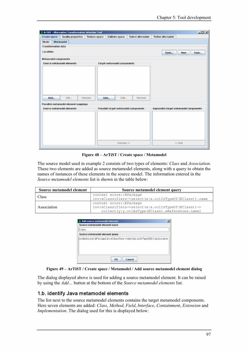
Chapter 5: Tool development
97
Figure 48 – ArTiST / Create space / Metamodel
The source model used in example 2 consists of two types of elements: Class and Association. These two elements are added as source metamodel elements, along with a query to obtain the names of instances of these elements in the source model. The information entered in the Source metamodel elements list is shown in the table below: Source metamodel element Source metamodel element query
Class context ecore::EPackage inv:eClassifiers->select(x|x.oclIsTypeOf(EClass)).name
Association context ecore::EPackage inv:eClassifiers->select(x|x.oclIsTypeOf(EClass))-> collect(y|y.oclAsType(EClass).eReferences.name)
Figure 49 – ArTiST / Create space / Metamodel / Add source metamodel element dialog
The dialog displayed above is used for adding a source metamodel element. It can be raised by using the Add… button at the bottom of the Source metamodel elements list.
1.b. identify Java metamodel elements The list next to the source metamodel elements contains the target metamodel components. Here seven elements are added: Class, Method, Field, Interface, Containment, Extension and Implementation. The dialog used for this is displayed below:

Tool support for the selection of alternatives in MDA model transformation
98
Figure 50 – ArTiST / Create space / Metamodel / Add target metamodel component dialog
The same dialog can be used to add patterns, but because this is a separate activity in the process, this is performed later on.
1.c. cross product UML and Java metamodel elements When adding new source metamodel elements and target metamodel components, all three lists inside Possible target metamodel element mappings are kept up to date. New source metamodel elements will be created with all target metamodel elements and possible mappings, whereas target metamodel patterns are added as impossible mappings by default. New target metamodel components are added as possible mappings when the type of the components is element, otherwise they well be added as impossible mappings.
Figure 51 – ArTiST / Create space / Metamodel / Possible metamodel element mappings
Because all seven target metamodel components entered are of type element, all are marked as possible target metamodel mappings for UML Class.
1.d. exclude impossible mappings With the two buttons placed at the bottom-right of the screen, each mapping for the selected source metamodel element can be marked as possible or impossible. The mappings contains by both list can be moved from one list to the other and visa versa.

Chapter 5: Tool development
99
Figure 52 – ArTiST / Create space / Metamodel / Possible metamodel element mappings
Because only the mappings for one source metamodel element can be visible at a given time, the mappings for both source metamodel elements are displayed in a table:
Source metamodel elements Possible target metamodel components
Impossible target metamodel components
Class Class Method Field Interface
Containment Extension Implementation
Association Containment Class Method Field Interface Extension Implementation
1.e. add mappings using patterns Four target metamodel patterns are added to the Target metamodel components list using the same dialog used to add target metamodel elements, but now with the radio button Pattern selected:
Figure 53 – ArTiST / Create space / Metamodel / Add target metamodel component dialog (2)

Tool support for the selection of alternatives in MDA model transformation
100
New target metamodel patterns are added as impossible mappings by default, so patterns that are considered as possible mappings for a source metamodel element should be moved to the other set after the pattern is added. For UML Class the strategy pattern is considered as a possible mapping:
Figure 54 – ArTiST / Create space / Metamodel / Possible metamodel element mappings (2)
The mappings for UML Association, which are not visible in the screenshot, can be found in the following table:
Table 36 – Library example 2, possible mappings to components entered in tool
Source metamodel elements Possible target metamodel components
Impossible target metamodel components
Class Class Method Field Interface PStrategy [pattern]
Containment Extension Implementation AssocClass [pattern] AssocMethods [pattern] AssocFields [pattern]
Association Containment AssocClass [pattern] AssocMethods [pattern] AssocFields [pattern]
Class Method Field Interface Extension Implementation PStrategy [pattern]
1.f. define source model The source model is first defined in Ration Rose as a UML class diagram and saved as a Model file (.mdl). The graphical representation is shown in Figure 55.

Chapter 5: Tool development
101
Figure 55 – UML Class Diagram (library example 2)
This Ration Rose Model file is imported into Eclipse using the following sequence of steps: File → New → Other… → Eclipse Modeling Framework → EMF Project. When asked for a Project name, Library example 2 is entered, the radio button Load from a Rose class model is selected and the Ration Rose Model file to be imported is selected. Then a package has to be selected from the imported Model file, in this case the libraryexample2 package is selected and then the Ecore model is generated:
Figure 56 – EMF Ecore model (library example 2)
Table 37 – EMF Ecore model contents
Icon Ecore type Source model element EPackage libraryexample2 EClass Library, Search, Sort EReference search, sort
To obtain the Ecore model as a XMI serialized XML document, one could copy the file from the workspace, or use Eclipse to export the model: File → Export… → File system; select library.example.2.ecore and a directory to store the file. Now the Ecore model is available as an XML document named library.example.2.ecore. Rose Enterprise Edition Release Version 2003.06.12.00.000 Eclipse SDK Release 3.0.1 (Build id: 200409161125) EMF, SDO & XSD SDK Release 2.0.1
1.g. create dimensions The file library.example.2.ecore, which contains the source model, is loaded into the tool by selecting it from a file chooser which is raised after pressing the Open… button.

Tool support for the selection of alternatives in MDA model transformation
102
Figure 57 – ArTiST / Create space / Model
The queries entered with each source metamodel element are applied on the source model, resulting in sets with names of source model elements. These names, along with the type of the element separated by a colon, are placed in the list Source model elements. The list next to these source model elements, named Target metamodel components, contains the possible mappings to target metamodel components, instantiated from the set of possible target metamodel components, for the selected source model element.
The number of alternatives shown in the screenshot is calculated by multiplying the size of the sets of target metamodel components.
What is not visible in the screenshot is the creation of a target skeleton space. This space is called 'skeleton' by default. Displayed here below are the facts added to the prolog database (in the definition of SLibrary2 in example 2 some different names used): dimensions('skeleton', ['Library','Search','Sort','sort','search']) coordinateSet('skeleton', 'Library', ['Class','Method','Field','Interface','PStrategy']) coordinateSet('skeleton', 'Search', ['Class','Method','Field','Interface','PStrategy']) coordinateSet('skeleton', 'Sort', ['Class','Method','Field','Interface','PStrategy']) coordinateSet('skeleton', 'sort', ['AssocClass','AssocMethods','AssocFields','Containment']) coordinateSet('skeleton', 'search', ['AssocClass','AssocMethods','AssocFields','Containment'])
3. reduce target skeleton space
3.c. define reduction operation To limit the amount of possible coordinates, heuristic rule (48) is applied to compel the same mappings for Search and Sort and for search and sort (names of the EReferences; in example 2 the names Library-Search and Library-Sort are used for the Associations). The operation '=' is used to indicate that form both dimensions the same coordinate should be selected (the operation '=>' will be introduces later on in this section).

Chapter 5: Tool development
103
Figure 58 – ArTiST / Reduce space / Model / Add reduction operation
The two reduction operations that operate on (the target skeleton space created from) the source model are displayed in the second list in the screenshot below.
Figure 59 – ArTiST / Reduce space / Model
3.d. apply reduction operation The operations are added as facts (or rules) to the prolog database (daSelect is used instead of select, because select is already defined): daSelect from 'skeleton' where 'Search' = 'Sort' daSelect from 'skeleton' where 'search' = 'sort' In theory this reduces the space to 5 * 5 * 4 = 100 alternatives, but the tool calculates an estimation of the number of alternatives in this step, because otherwise all alternatives would have to be generated. Because both reduction operations operate on more than one dimension (the estimation method used only considers operations that operate on one dimension), the number of alternatives is still calculated as 2000.

Tool support for the selection of alternatives in MDA model transformation
104
2. assign quality requirement
2.a. define quality model One quality model is defined, consisting of two quality properties. In example 2 the properties InAdapt and AdaptRT are defined. When creating a new quality model in the tool, one quality property is created by default: Not required. This quality property is selected by default when an alternative has to be selected. The property InAdapt from example 2 can be replaces by this default quality property. AdaptRT is renamed to Run-time adaptable feature.
Figure 60 – ArTiST / Quality properties / Metamodel
3.b. create quality model space A quality model space is automatically created by the tool when one of the quality properties is selected for a source model element (dimension). This will be performed in the next step, but the result can already be shown here (not visible to the user): dimensions('Adaptability', ['Library','Search','Sort','sort','search']) coordinateSet('Adaptability', 'Library', ['Not required' 'Run-time adaptable feature']) coordinateSet('Adaptability', 'Search', ['Not required' 'Run-time adaptable feature']) coordinateSet('Adaptability', 'Sort', ['Not required' 'Run-time adaptable feature']) coordinateSet('Adaptability', 'sort', ['Not required' 'Run-time adaptable feature']) coordinateSet('Adaptability', 'search', ['Not required' 'Run-time adaptable feature'])
3.c. select quality model alternative

Chapter 5: Tool development
105
Figure 61 – ArTiST / Quality properties / Model
The selection of a quality model alternative is done by adding (or replacing) quality properties of a quality model to source model elements (one per element). When the first quality property of a quality model is added to a source model element, the default quality property of the model is assigned to all other source model elements. These assigned quality properties can be replaced by other properties. With the selected properties a reduction operation can be created, reducing the space to oen that contains only one alternative: daSelect from 'Adaptability' where 'Library' => 'Not required' and 'Search' => 'Run-time adaptable feature' and 'Sort' => 'Run-time adaptable feature' and 'sort' => 'Not required' and 'search' => 'Not required'
2. reduce target skeleton space (2)
2.a. define reduction operation template
Figure 62 – ArTiST / Reduce space / Metamodel / Add reduction operation template
The reduction operation template added to map UML Class to Java PatternStrategy is shown in the figure above. The word RESULT in the two text areas at bottom of the popup is a variable for the results obtained by the query.
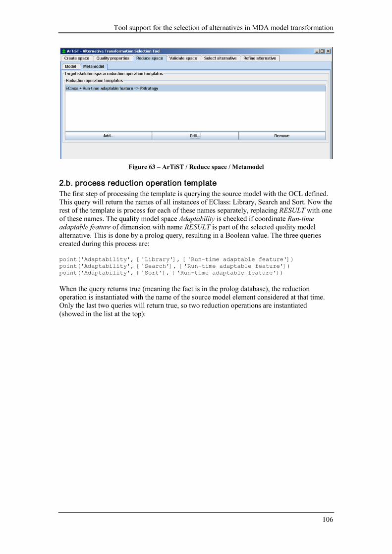
Tool support for the selection of alternatives in MDA model transformation
106
Figure 63 – ArTiST / Reduce space / Metamodel
2.b. process reduction operation template The first step of processing the template is querying the source model with the OCL defined. This query will return the names of all instances of EClass: Library, Search and Sort. Now the rest of the template is process for each of these names separately, replacing RESULT with one of these names. The quality model space Adaptability is checked if coordinate Run-time adaptable feature of dimension with name RESULT is part of the selected quality model alternative. This is done by a prolog query, resulting in a Boolean value. The three queries created during this process are: point('Adaptability', ['Library'], ['Run-time adaptable feature']) point('Adaptability', ['Search'], ['Run-time adaptable feature']) point('Adaptability', ['Sort'], ['Run-time adaptable feature']) When the query returns true (meaning the fact is in the prolog database), the reduction operation is instantiated with the name of the source model element considered at that time. Only the last two queries will return true, so two reduction operations are instantiated (showed in the list at the top):

Chapter 5: Tool development
107
Figure 64 – ArTiST / Reduce space / Model
3.d. apply reduction operation The reduction operations are applied by adding them as facts to the prolog database: daSelect from 'skeleton' where 'Search' => 'PStrategy' daSelect from 'skeleton' where 'Sort' => 'PStrategy' The number of alternatives is decreased to 80 (theoretically it is 20, but the estimation does not take both additional reduction operations into account). The number of alternatives still corresponds with the number calculated in example 2, but from now on there will be a difference. Rule (81) defined in example 2 cannot be process by the tool, because tuples returned by source model queries cannot be handled yet and this rule requires tuples.
4. validate target skeleton space This activity is not yet implemented.
5. select target skeleton alternative

Tool support for the selection of alternatives in MDA model transformation
108
Figure 65 – ArTiST / Select alternative / Model
All 20 alternatives are presented in a list. Selection is still not possible, because the refinement activity is not yet implemented. This number is larger than the number in example 2, because the last reduction operation template could not be used with the tool and the validation of the space is also not possible. Therefore there are 20 alternatives instead of 6.
6. refine target skeleton alternative This activity is not yet implemented.
5.5.3 Case study: Examination Questionnaires In this section the example transformation from UML to XML performed in Chapter 3.2 is elaborated again, but now with the help of the tool. Because the main purpose of this section is to show that the tool is not fixed to one target metamodel, only the most important screens are shown and important differences are discussed.
1. create target skeleton space The definition of the source model is performed by importing the UML class diagram of Figure 12 into Eclipse, the same way as described in the previous section.

Chapter 5: Tool development
109
Figure 66 – EMF Ecore model (examination questionnaires)
What is different this time is the name of the association (aggregation). Where in the previous example the name of the EReference was created with lowercase letters, here the first character is in upper case. This is not desired, because now there are two model elements with the same name (ExamItem). Therefore the XMI file is changed to make the name of the EReference start with a lower case letter: <eClassifiers xsi:type="ecore:EClass" name="Exam"> <eStructuralFeatures xsi:type="ecore:EReference" name="ExamItem" upperBound="-1" eType="#//ExamItem"/> <eStructuralFeatures xsi:type="ecore:EReference" name="examItem" upperBound="-1" eType="#//ExamItem"/> </eClassifiers> Another difference is the presence of two specialization classes. In the graphical Ecore model this is visible by the '->' in the names of the classes. Instances of EClass also contain this information in a property named eSuperTypes, which contains the superclasses as values, as can be seen in the XMI file: <eClassifiers xsi:type="ecore:EClass" name="ExamItem"/> <eClassifiers xsi:type="ecore:EClass" name="Open" eSuperTypes="#//ExamItem"/> <eClassifiers xsi:type="ecore:EClass" name="MultipleChoice" eSuperTypes="#//ExamItem"/> There is no separate element in Ecore to represent an UML Generalization. Because the example in Chapter 3.2 identified generalization as a source metamodel element, such an element should be added here also. This element is called Generalization (no E prefix, because it is no part of EMF) and is created for every EClass listed in the eSuperTypes property of all EClass instances. Formulating this in OCL results in the following expression: context ecore::EPackage inv:eClassifiers->select(x|x.oclIsTypeOf(EClass))-> collect(y|y.oclAsType(EClass).eSuperTypes-> collect(z|y.oclAsType(EClass).name.concat(' -> '). concat(z.oclAsType(EClass).name))) The rest of the metamodel-based transformation data entered in the first activity corresponds to that defined in Chapter 3.2.

Tool support for the selection of alternatives in MDA model transformation
110
Figure 67 – ArTiST / Create space / Metamodel
The identified source model elements are listed in the screenshot below:
Figure 68 – ArTiST / Create space / Model
Two types of reduction operation templates are added: one excludes mappings and the other selects mappings. Templates of the first type are more or less redundant, because no excluded elements are selected in this example.

Chapter 5: Tool development
111
Figure 69 – ArTiST / Reduce space / Metamodel
The instantiated operations from these templates are displayed below:
Figure 70 – ArTiST / Reduce space / Model
Only four alternatives remain when all reduction operations are applied:

Tool support for the selection of alternatives in MDA model transformation
112
Figure 71 – ArTiST / Select alternative / Model
This number corresponds to the number found in Chapter 3.2.
5.6 Evaluation The first phase in the development of the tool was to understand and define the process for the selection of alternatives the tool should support. Chapter 3 demonstrates the application of the most refined version of such a process that is available.
Chapter 4 defines an adapted version of that process, illustrated with activity diagrams and examples. Special attention is paid not to make use implicit information in the process, so the whole process could to be performed by the tool. The examples included in Chapter 4 are executed from the viewpoint of one user.
In the first section of Chapter 5 use cases are introduced, where each activity is placed under one of the two actors identified: metamodel-based transformation definer and model-based transformation selector. This distinction of actors makes it possible to reuse a transformation specification with different instances of the metamodels used. To make the requirements for the tool more explicit, natural language is used to describe the requirements based on the annotated activity diagrams. Using all the information gathered in the previous activities, screenshots of the tool are designed, showing different screens for each activity in the process.
After the first section it is clear what the tool should support, but not how. By generalizing the requirements some key components are determined, leading to an architecture. Based on this architecture, existing languages, specification and libraries are gathered, evaluated and some are selected to be used to realize an implementation of the tool.
Section three and four describe the design and the implementation of the tool. Both phases do not cover all six activities the tool should support, due to a limited amount of time to finish the implementation. The creation and reduction of the target skeleton space are implemented, along with the assignment of quality properties and the selection of an alternative target skeleton. The validation of the target skeleton and the whole refinement of the selected target skeleton are not implemented.
The result is a prototype that is capable of supporting a certain range of metamodel-based transformations (source model must be (transformed to) Ecore). This is demonstrated in the last section, where two examples presented earlier in this thesis, one from UML to XML and the other from UML to Java, are executed again, but now with the tool to support the process. The tool supports the metamodel-based transformation definer in creating the (unidirectional) transformation specification between two metamodels and when a source model has to be transformed the tool takes care of everything that does not require information from the model-based transformation selector.

Chapter 6: Conclusions and recommendations
113
6 Conclusions and recommendations This chapter starts with a summary of the thesis; followed by conclusions regarding to what extent the goals presented in the problem statement are reached. Parts of goals that are not completely realized are presented as recommendations, along with other ideas for further research that did not fit into the scope of this project or that would have taken too much time to look at.
6.1 Conclusions Chapter 1 starts will a description of the background of the problem. The background consists of model transformations in MDA, especially metamodel-based transformations. To handle the large amount of alternative transformations that are possible between source and target metamodel constructs, design algebra is used. Heuristic rules, in combination with different desired quality properties for the target model, and target model constraints can be used to decrease the number of alternatives. Tool support to guide this process is desired, because a large part of the work can be automated, moving the focus of the user to the definition of heuristic rules, instead of managing all alternatives and applying heuristic rules.
Brief explanations about the concepts used in this thesis can be found in Chapter 2, such as MDA, design algebra and MOF related concepts.
In Chapter 3 an evaluation of the most refined process available for the selection of alternative transformations is provided. Some possible problems with the process regarding tool support are identified, of which the ambiguous way to handle patterns in the process and the lack of a detailed description of the refinement phase are the most important.
Chapter 4 provides solutions for the problems identified Chapter 3. Three different types of patterns are distinguished: source model patterns, target model patterns and a combination of these two. Target model patterns are most suitable to be used with design algebra. Source model patterns can be used, but with limitations. The process of the selection of alternative transformations is defined in Chapter 4 also, including support for patterns.
In Chapter 5 the development of the tool is discussed. A framework is determined to handle not only one combination of source and target model types, but a wider range. The resulting tool is capable supporting the modeling, reduction (possibly based on quality requirements) and selection of alternatives for a given source model, and the definition of the modeling of alternative transformations, quality models and reduction operations on these alternatives for a combination of source and target metamodel.
Referring back to the problem statement in Chapter 1.3: The aim of this project is to realize a tool that supports the selection of alternatives in MDA model transformations. This goal is not completely achieved, because not all the activities that are part of the selection of alternatives are implemented. The resulting tool does support the selection of alternatives, but does not support the refinement of the selected alternative skeleton. Although not implemented, this activity is defined with as much detail as the other activities, is demonstrated in all examples, included in the in the analysis of tool and taken into account when designing the tool. Evaluating each of the four objectives stated in Chapter 1.3: - define the process of alternatives selection
The process for the selection of alternatives is divided into six activities: create target skeleton space, reduce the space, validate remaining alternatives, select an alternative to be refined and refine the selected target skeleton into a (transformation to a) target model. Five of the six

Tool support for the selection of alternatives in MDA model transformation
114
activities are divided into a process with more detailed sub-activities. The whole process is illustrated with three examples, following the process as defined within the activities.
- describe how patterns can be used in the process
Because the process of alternatives selection makes use of design algebra to model all alternatives, source model patterns are difficult to implement, because source model elements are represented with a fixed set of dimensions. One must decompose the source model pattern into smaller target model patterns, each having only one corresponding element in the source model. The relation between these target model patterns must then be constraint in the target metamodel, resulting in a set of source model elements that are mapped to a set of target model components, constrained by the target metamodel. Target model patterns are a lot easier to use in combination within design algebra, because patterns can be just added as coordinates to dimensions. Table 38 shows that all mappings should and can be implemented using singe-to-any mappings. None-to-any mappings require an additional source model element and multiple-to-any mappings require special constraints in the target metamodel, as mentions when discussing source model patterns.
Table 38 – Possible multiplicities when mapping source to target elements
source \ target none (0)
single (1)
multiple (2+)
none (0) not useful part of 1→1+ part of 1→2+
single (1) empty pattern element pattern
multiple (2+) multiple 1→0+ multiple 1→0+ multiple 1→0+
The patterns are replaced by single target model elements in the refinement phase of alternatives generation. The special adjustments to the activities are defined in the definition of the alternatives selection process.
- determine a framework to handle a wide range of metamodel-based transformations
The framework chosen is not the most ideal, because that would be probably MOF in combination with OCL, but is restricted by the available implementations and the possible combinations of these implementations. The framework chosen to be used for the tool is based on Ecore in combination with OCL. Ecore is the metamodel used in the EMF, a modeling framework for Eclipse. Ecore is comparable to MOF, but it is more adapted for tool support. OCL is used to query the source model, which is necessary to support heuristic rules.
- implemented a tool that supports the process defined, using the framework
The tool is developed for the Java platform, utilizing existing implementation such as the selected framework consisting of EMF and the Kent OCL Library. This framework is used to handle the source models. Prolog is used to model and reduce the various spaces used in the process and to search for all alternatives remained of the reduction.
The tool created during this project, although it is not completely implemented, shows that the approach to model transformations as suggested by Kurtev [12] is practical. It also shows that good tool support is required, because without the amount of information becomes a burden to work with. But when having good tool support for the complete process, from source model to target model, it can help to realize will-balanced model transformation in MDA.
6.2 Recommendations Because there was limited time for the implementation, not everything is implemented and what is implemented can sometimes be made better. Some recommendations:

Chapter 6: Conclusions and recommendations
115
- Extend the implementation with full support for the refinement phase. This phase is particularly interesting, because there the target model patterns become visible and results in a refined target model alternative (represented as an alternative transformation) that can be used to transform the source model without any other interaction.
- Instead of using Prolog to model the spaces, a relational database can be used. This can result in a major improvement of the performance.
- Instead of storing the metamodel-bases transformation data as serialized binary objects, XML can be used. Then the data can be still used after changes are mode to the classes involved in serialization.
- Not all reduction operations presented in this thesis can be handled by the tool. The tool does not take possible tuples that can be the result of query into account. When implementing this, the variables in reduction operation templates should be numbered.
- When finishing this thesis, the Dresden OCL Toolkit seems to have developed OCL evaluation in combination with the MDR. By replacing the EMF with MDR, more source model types can be supported. This can also be realized by developing a bridge between the Kent OCL Library and the MDR.
With the current approach, where heuristic rules rely on the presence of quality requirements, it is not possible to combine patterns when more than one quality property is required for an element. Separate patterns are needed for each combination of quality requirements. It would be better to determine the quality properties of target model, instead of creating target models that have certain quality properties. But than all target models must be generated, which was not possible because of the large number of alternatives. Maybe there is an intermediate approach possible.
The identification of source model patterns, relying on target model patterns and the target skeleton metamodel, is not really usable at the moment. Also the usage of patterns as target model components has its limitation and drawbacks. These problems can be carried back to the one-to-one relations between dimensions and coordinates in alternatives. Maybe the identification of source model patterns should be new, separate phase in alternatives generation. Even with the application of heuristic rules and target model validation, a lot of alternatives may remain. When these alternatives are rated or quantified, for example based on priorities as with design algebra or determined by the quality properties of the alternative, an ordered list can be presented to the user.

Tool support for the selection of alternatives in MDA model transformation
116
References [1] AndroMDA, AndroMDA Model Driven Architecture Framework, www.andromda.org [2] Svata Dedic, Martin Matula, Metamodel for the Java language, (Revision: 1.5),
http://java.netbeans.org/models/java/java-model.html [3] Jan Dockx, Kristof Mertens, Nele Smeets, Eric Steegmans (2001). jnome: A Java Meta
Model in Detail. Report CW 323, Department of Computer Science KULeuven [4] Eclipse Foundation, Eclipse Project, http://www.eclipse.org/eclipse [5] Eclipse Foundation, Eclipse Tools - EMF Documents – The Eclipse Modeling
Framework (EMF) Overview, http://www.eclipse.org/emf/docs.php?doc=references/overview/EMF.html
[6] Eclipse Foundation, Eclipse Tools - EMF, SDO, XSD, http://www.eclipse.org/emf [7] Gamma, Helm, Johnson, Vlissides (1994), Design Patterns, Elements of Reusable
Object-Oriented Software, Addison-Wesley [8] Gardner, Tracy, Griffin, Catherine, Koehler, Jana, Hauser, Rainer, A review of OMG
MOF 2.0 Query / Views / Transformations Submissions and Recommendations towards the final Standard, Object Management Group, document ad/2003-08-02
[9] James Gosling, Bill Joy, Guy Steele, Gilad Bracha (June 5, 2000), Java(TM) Language Specification (2nd Edition), Addison-Wesley
[10] Gunawan, L.A. (2003). Mapping UML Domain Models onto XML Schemas using UML Profiles. MSc Thesis Telematics, University of Twente
[11] Klasse Objecten, OCL tools and services, http://www.klasse.nl/ocl/ocl-services.html [12] Kurtev, I., Berg, K. G., Aksit, M. (2003). UML to XML-Schema Transformation: a
Case Study in Managing Alternative Model Transformations in MDA. Forum on specification and Design Languages FDL2003, Frankfurt
[13] Miller, Joaquin; Mukerji, Jishnu, ed. (2001), Model Driven Architecture, Object Management Group, document ormsc/2001-07-01
[14] Miller, Joaquin; Mukerji, Jishnu, ed. (2003), MDA Guide Version 1.0.1, Object Management Group, document omg/2003-06-01
[15] Object Management Group, http://www.omg.org/memberservices/index.htm, Membership Information
[16] Object Management Group (October 2003), Meta Object Facility (MOF) 2.0 Core Specification (Final Adopted Specification), Object Management Group, document ptc/03-10-04
[17] Object Management Group (October 2003), UML 2.0 OCL Specification (Final Adapted Specification), Object Management Group , document ptc/2003-10-14
[18] Object Management Group (April 24, 2002), Request for Proposal: MOF 2.0 Query / Views / Transformations RFP, Object Management Group, document ad/2002-04-10
[19] Object Management Group (August 2003), UML 2.0 Superstructure (Final Adopted Specification), Object Management Group, document ptc/03-08-02
[20] Object Management Group (December 2003), UML 2.0 Infrastructure (Final Adopted Specification), Object Management Group, document ptc/03-09-15
[21] Object Management Group (May 2003), XML Metadata Interchange (XMI), v2.0, Object Management Group, document formal/03-05-02
[22] David Hearnden, Kerry Raymond, Jim Steel, MQL: a Powerful Extension to OCL for MOF Queries, Proc. 7th IEEE International Enterprise Distributed Object Computing Conference (EDOC 2003), Brisbane, Sept 2003, pp 264-276
[23] Sari, A. (2004). Mapping UML Class Models into XML Schemas using UML Profiles. Msc Thesis Telematics, University of Twente
[24] Schrijvers, T., Constraint Handling Rules (CHR), http://www.cs.kuleuven.ac.be/~dtai/projects/CHR/
[25] Singleton, P., JPL: A bidirectional Prolog/Java interface, http://www.swi-prolog.org/packages/jpl

Chapter 6: Conclusions and recommendations
117
[26] Sun Micorsystems, Inc., Java Metadata Interface (JMI), http://java.sun.com/products/jmi/index.jsp
[27] SWI-Prolog, SWI-Prolog, http://www.swi-prolog.org [28] Tekinerdogan, B. (2000), Synthesis-Based Software Architecture Design, PhD thesis
Universisty of Twente, Enschede, The Netherlands [29] University of Kent, Object Constraint Language Library,
http://www.cs.kent.ac.uk/projects/ocl/index.html [30] Wahler, M., Using OCL to interrogate your EMF model,
http://www.zurich.ibm.com/~wah/doc/emf-ocl/ [31] World Wide Web Consortium, XML Path Language (XPath) Version 1.0,
http://www.w3.org/TR/1999/REC-xpath-19991116 [32] World Wide Web Consortium, XQuery 1.0: An XML Query Language (Working Draft
23 July 2004), http://www.w3.org/TR/2004/WD-xquery-20040723

Tool support for the selection of alternatives in MDA model transformation
118
A GUI design The process can be divided into six activities, as is shown in the main activity diagram in Figure 22. Because all activities depend on information selected or entered in previous activities, displaying only one activity at a time, for example by using six tabular pages, should be a good starting point for the design of the GUI. Most activities can be viewed on two levels, depending on the actor involved: the metamodel-based transformation definer and the model-based transformation selector. In most activities information shown at the model-level is generated using information entered at the metamodel-level. Therefore on each of the six tabular pages, two tabular pages are placed: model and metamodel.
A.1 Activity 1 - Create target skeleton space
Model Related activities / requirements: 1.f. define source model 1.g. create dimensions with coordinates A.1. unload source model
Figure 72 – GUI: Create space – Model
The user can load a source model from a file and the tool will create a dimension for each source model element (shown in Source model elements list), based on the identified source metamodel elements in the Metamodel tab. For each dimension a set of coordinates is created (shown in the Target model components list), based on the identified target metamodel components in the Metamodel tab. The initial number of alternatives is calculated based on size of the coordinate sets. The actual space, or the set of all alternatives, is not visible for the user until the fifth activity: Select alternative.
Metamodel Related activities / requirements: 1.a. identify source metamodel elements 1.b. identify target metamodel elements 1.c. cross product metamodel elements 1.d. exclude impossible mappings

Chapter 6: Conclusions and recommendations
119
1.e. add possible mappings using patterns A.2. save metamodel-based transformation data A.3. load metamodel-based transformation data
Figure 73 - GUI: Create space – Metamodel
The user can load and save all metamodel-based transformation data. This is the information entered by the user in all Metamodel tabs. The data displayed in this screen consists of four sets: source metamodel elements, target metamodel elements, per source metamodel element a set of possible target metamodel elements (subset of target metamodel elements) and also per source metamodel element a set of additional target metamodel patterns. For the target metamodel patterns the same approach as provided for the target metamodel elements could be used, where each source metamodel element has a subset of one central set of elements. Initially the set of possible target metamodel elements for a source metamodel element consists of all identified target metamodel elements (so when looking at all the source metamodel elements, a cross product is performed using all identified source and target metamodel elements).
A.2 Activity 2 - Assign quality requirement
Model

Tool support for the selection of alternatives in MDA model transformation
120
Related activities / requirements: 2.b. create quality model space 2.c. select quality model alternative
Figure 74 - GUI: Quality properties - Model
By selecting one quality property from a quality model, the tool creates a quality model space using the identified source model elements and the quality model of the selected quality property. An alternative from this quality model space is selected, making use of a default quality property for elements where no property is selected.
Metamodel Related activities / requirements: 2.a. define quality model
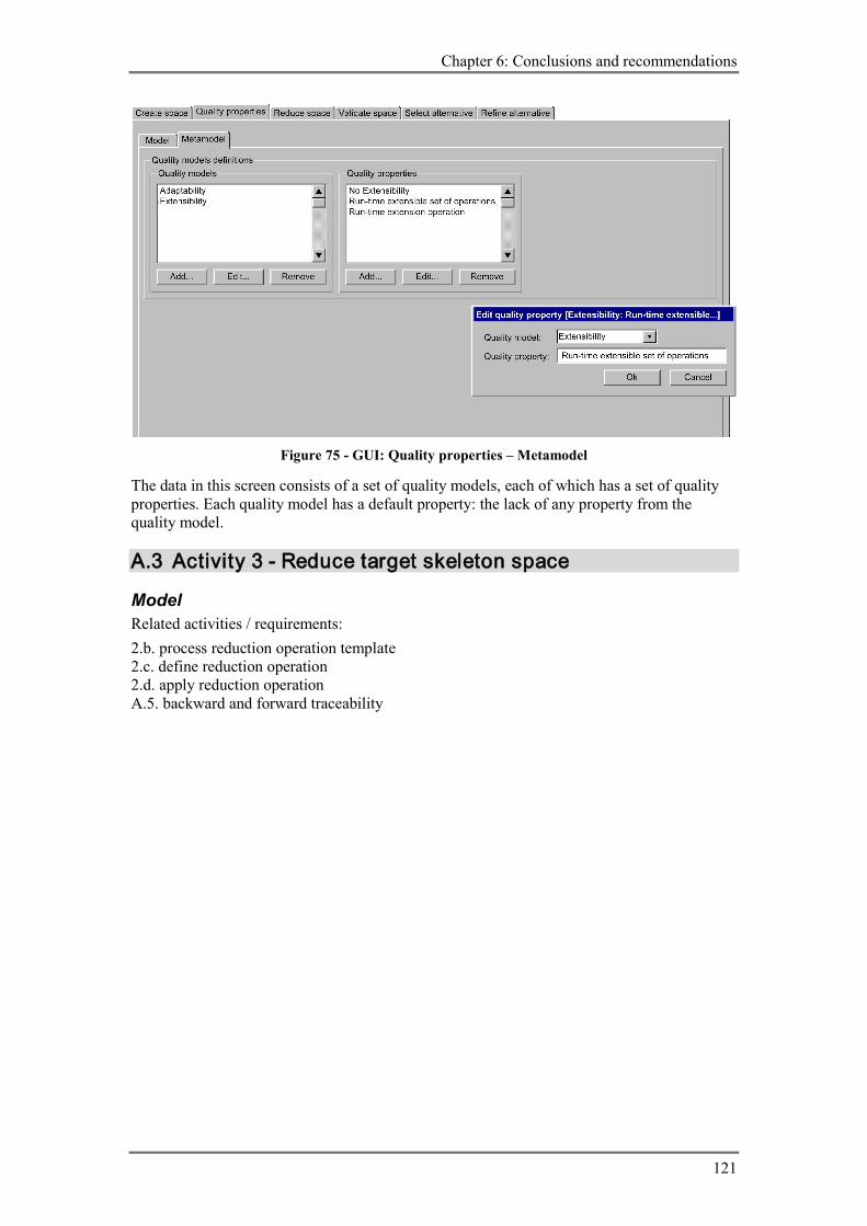
Chapter 6: Conclusions and recommendations
121
Figure 75 - GUI: Quality properties – Metamodel
The data in this screen consists of a set of quality models, each of which has a set of quality properties. Each quality model has a default property: the lack of any property from the quality model.
A.3 Activity 3 - Reduce target skeleton space
Model Related activities / requirements: 2.b. process reduction operation template 2.c. define reduction operation 2.d. apply reduction operation A.5. backward and forward traceability

Tool support for the selection of alternatives in MDA model transformation
122
Figure 76 - GUI: Reduce space – Model
The result of processed reduction operations templates defined in the Metamodel tab are reduction operations. These generated reduction operations are displayed in the first list in this screen, along with the template that instantiated the operation. The user can add additional reduction operations in the second list. To make it possible for the user to exclude some of the (generated) rules, checkboxes are placed in front of each operation. The bottom half of the screen shows the resulting space as two sets, where the second set (Selected target model components) depends on the first set (Source model elements). Note that the result of operations where more than one dimension is involved cannot be made visible in this way. To give and estimation about the number of alternatives after the reduction operations are applied, this number is displayed at the bottom of the screen.
Metamodel Related activities / requirements: 3.a. define reduction operation template A.5. backward and forward traceability

Chapter 6: Conclusions and recommendations
123
Figure 77 - GUI: Reduce space – Metamodel
This screen shows how reduction operation templates can be entered. A name is added to each template, to reflect the intention of the template (is also used for traceability). Each template consists of three parts: a query for the selection of source model elements, an (optional) condition for the required quality properties of the target model and a reduction operation, which uses the names returned by the source model query.
A.4 Activity 4 - Validate target skeleton space
Model Related activities / requirements: 4.b. validate alternatives

Tool support for the selection of alternatives in MDA model transformation
124
Figure 78 - GUI: Validate space – Model
The validation of alternatives is performed by the tool, based on the information entered at the Metamodel tab. The only visible result to the user is the decrease of the number of alternatives, which is displayed in the next activity.
Metamodel Related activities / requirements: 4.a. define target skeleton metamodel
Figure 79 - GUI: Validate space – Metamodel

Chapter 6: Conclusions and recommendations
125
The screen represents one possible way to define a target skeleton metamodel. In an ideal situation the metamodel would be for example an MOF compliant metamodel with OCL to define constraints. The first list contains a selection of top-level components. The name top-level is used to denote that the component can exist without being part of or contained by another component, for example an Attribute is not a valid target model element if it is not contained by a class. This feature of component could also be defined by adding a column and row called none to the table with valid directed relationships. The two lists in the second row make it possible to differentiate between components that represent a relationship and components that do not. This is important for the next step, where it is assumed that all non-relational components are connect to each other by relational ones. The table displayed in the screen shows the valid relations between non-relational components. Because no information about relationships is present in the target skeleton space, this has to be derived from the source model. Therefore the box with endpoint definitions is included in the screen.
A.5 Activity 5 - Select target skeleton alternative
Model
Figure 80 - Detailed GUI: Select space – Model
In this screen all possible, valid alternatives are shown as tuples (rows in the table). The table at the bottom of the screen shows the selected alternative (if any) that is the central subject in the next activity.
A.6 Activity 6 - Refine target skeleton alternative This activity can be seen as an iteration of most previous activities. For each target skeleton component zero, one or more refinement spaces are created. All these spaces should be reduced and the combination of all spaces should be validated. At the end one combination of target skeleton refinement alternatives should be selected.

Tool support for the selection of alternatives in MDA model transformation
126
A.6.1 Create target skeleton refinement spaces
Model Related activities / requirements: 6.a.IV. create target skeleton refinement spaces
Figure 81 – GUI: Refine alternative – Create space – Model
The components of the selected target skeleton are displayed in the left-most list. The list next to it contains the generated spaces for the selected target model component in the first list. For each target model element there will be one space, for each pattern any number of refinement spaces is possible. Each refinement space has a set of refinement properties; each property has a set of values. The names for the target model elements and the refinement values can be generated, using information from the source model obtained by queries defined in the Metamodel tab.
Metamodel Related activities / requirements: 6.a.I. define refinements for target metamodel elements 6.a.II. exclude invalid combinations of refinement values 6.a.III. define refinements for target metamodel patterns

Chapter 6: Conclusions and recommendations
127
Figure 82 - GUI: Refine alternative – Create space – Metamodel
The top half of the screen contains the definition of element refinements, the bottom half for pattern refinements. The list Target metamodel elements at the bottom of the screen is used to divide patterns into elements. The elements inside a pattern can be named using source model queries. This is shown in the Edit target metamodel element popup. Refinement values can also be created using source model queries. This is necessary to generate the right names for possible endpoints, as is shown in the Edit refinement value popup. Invalid combinations of refinement values, for example mutually exclusive values, can be defined during the definition of the target metamodel element refinements.
A.6.2 Reduce target skeleton refinement spaces
Model Related activities / requirements (the same as for activity 3 - reduce target skeleton space): 6.b.II. process reduction operation template 6.b.III. define reduction operation 6.b.IV. apply reduction operation A.5. backward and forward traceability

Tool support for the selection of alternatives in MDA model transformation
128
Figure 83 - GUI: Refine alternative – Reduce space – Model
The explanation of this screen is similar to that of activity 3.
Metamodel Related activities / requirements: 6.b.I. define reduction operation template
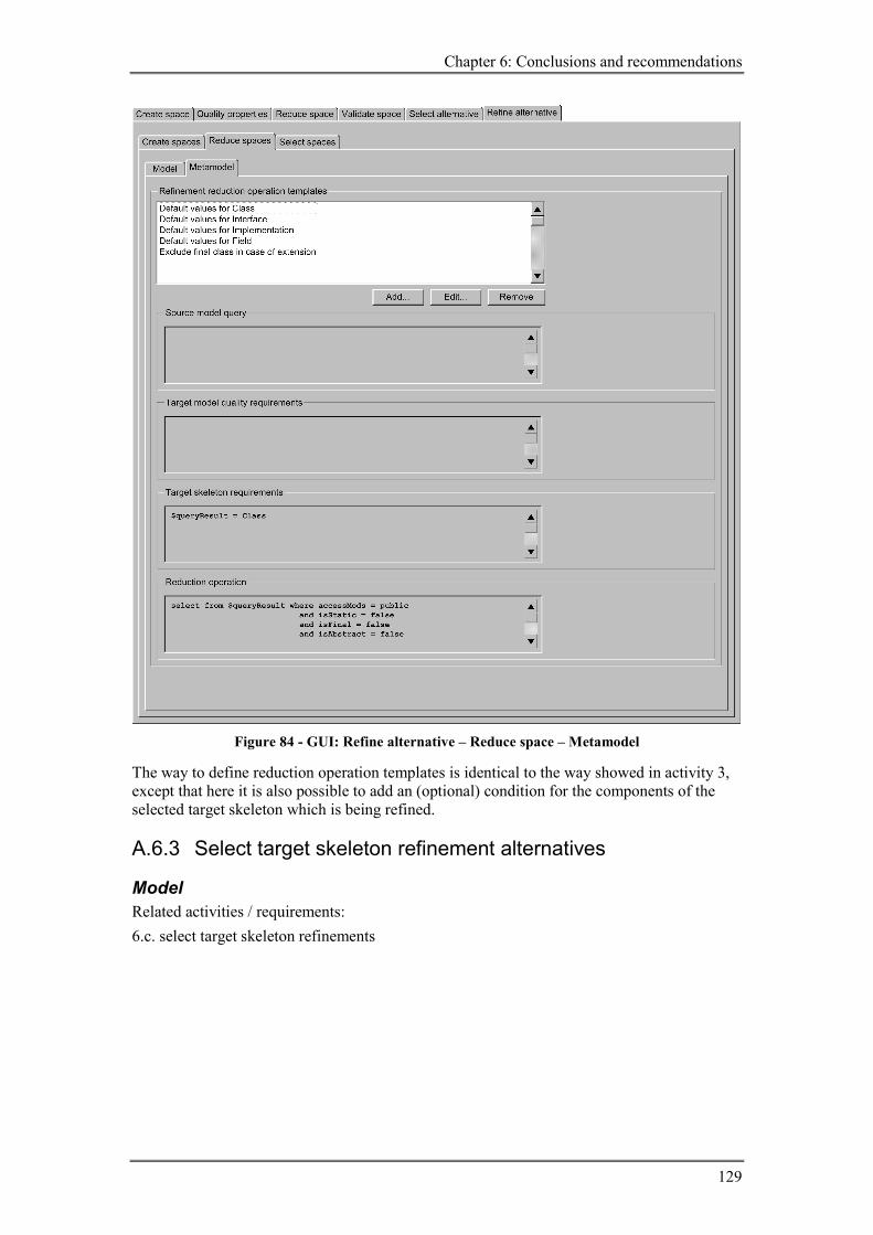
Chapter 6: Conclusions and recommendations
129
Figure 84 - GUI: Refine alternative – Reduce space – Metamodel
The way to define reduction operation templates is identical to the way showed in activity 3, except that here it is also possible to add an (optional) condition for the components of the selected target skeleton which is being refined.
A.6.3 Select target skeleton refinement alternatives
Model Related activities / requirements: 6.c. select target skeleton refinements

Tool support for the selection of alternatives in MDA model transformation
130
Figure 85 - GUI: Refine alternative – Select space - Model
All possible alternatives of the reduced space that is selected in the list of refinement spaces are shown as a list of tuples. The bottom table shows what alternative refinement is selected for each source model element.