Embed Size (px)
Citation preview
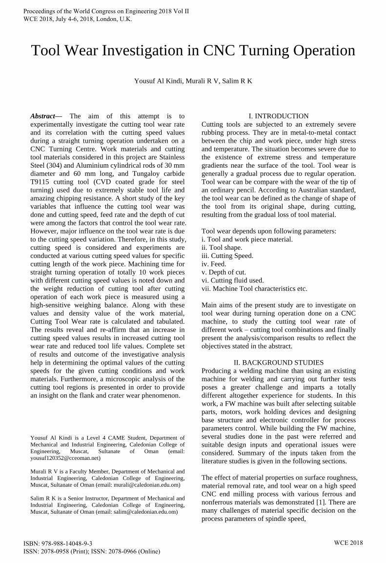
Tool Wear Investigation in CNC Turning Operation
Yousuf Al Kindi, Murali R V, Salim R K
Abstract— The aim of this attempt is to
experimentally investigate the cutting tool wear rate
and its correlation with the cutting speed values
during a straight turning operation undertaken on a
CNC Turning Centre. Work materials and cutting
tool materials considered in this project are Stainless
Steel (304) and Aluminium cylindrical rods of 30 mm
diameter and 60 mm long, and Tungaloy carbide
T9115 cutting tool (CVD coated grade for steel
turning) used due to extremely stable tool life and
amazing chipping resistance. A short study of the key
variables that influence the cutting tool wear was
done and cutting speed, feed rate and the depth of cut
were among the factors that control the tool wear rate.
However, major influence on the tool wear rate is due
to the cutting speed variation. Therefore, in this study,
cutting speed is considered and experiments are
conducted at various cutting speed values for specific
cutting length of the work piece. Machining time for
straight turning operation of totally 10 work pieces
with different cutting speed values is noted down and
the weight reduction of cutting tool after cutting
operation of each work piece is measured using a
high-sensitive weighing balance. Along with these
values and density value of the work material,
Cutting Tool Wear rate is calculated and tabulated.
The results reveal and re-affirm that an increase in
cutting speed values results in increased cutting tool
wear rate and reduced tool life values. Complete set
of results and outcome of the investigative analysis
help in determining the optimal values of the cutting
speeds for the given cutting conditions and work
materials. Furthermore, a microscopic analysis of the
cutting tool regions is presented in order to provide
an insight on the flank and crater wear phenomenon.
Yousuf Al Kindi is a Level 4 CAME Student, Department of
Mechanical and Industrial Engineering, Caledonian College of
Engineering, Muscat, Sultanate of Oman (email:
Murali R V is a Faculty Member, Department of Mechanical and
Industrial Engineering, Caledonian College of Engineering,
Muscat, Sultanate of Oman (email: [email protected])
Salim R K is a Senior Instructor, Department of Mechanical and
Industrial Engineering, Caledonian College of Engineering,
Muscat, Sultanate of Oman (email: [email protected])
I. INTRODUCTION
Cutting tools are subjected to an extremely severe
rubbing process. They are in metal-to-metal contact
between the chip and work piece, under high stress
and temperature. The situation becomes severe due to
the existence of extreme stress and temperature
gradients near the surface of the tool. Tool wear is
generally a gradual process due to regular operation.
Tool wear can be compare with the wear of the tip of
an ordinary pencil. According to Australian standard,
the tool wear can be defined as the change of shape of
the tool from its original shape, during cutting,
resulting from the gradual loss of tool material.
Tool wear depends upon following parameters:
i. Tool and work piece material.
ii. Tool shape.
iii. Cutting Speed.
iv. Feed.
v. Depth of cut.
vi. Cutting fluid used.
vii. Machine Tool characteristics etc.
Main aims of the present study are to investigate on
tool wear during turning operation done on a CNC
machine, to study the cutting tool wear rate of
different work – cutting tool combinations and finally
present the analysis/comparison results to reflect the
objectives stated in the abstract.
II. BACKGROUND STUDIES
Producing a welding machine than using an existing
machine for welding and carrying out further tests
poses a greater challenge and imparts a totally
different altogether experience for students. In this
work, a FW machine was built after selecting suitable
parts, motors, work holding devices and designing
base structure and electronic controller for process
parameters control. While building the FW machine,
several studies done in the past were referred and
suitable design inputs and operational issues were
considered. Summary of the inputs taken from the
literature studies is given in the following sections.
The effect of material properties on surface roughness,
material removal rate, and tool wear on a high speed
CNC end milling process with various ferrous and
nonferrous materials was demonstrated [1]. There are
many challenges of material specific decision on the
process parameters of spindle speed,
Proceedings of the World Congress on Engineering 2018 Vol II WCE 2018, July 4-6, 2018, London, U.K.
ISBN: 978-988-14048-9-3 ISSN: 2078-0958 (Print); ISSN: 2078-0966 (Online)
WCE 2018
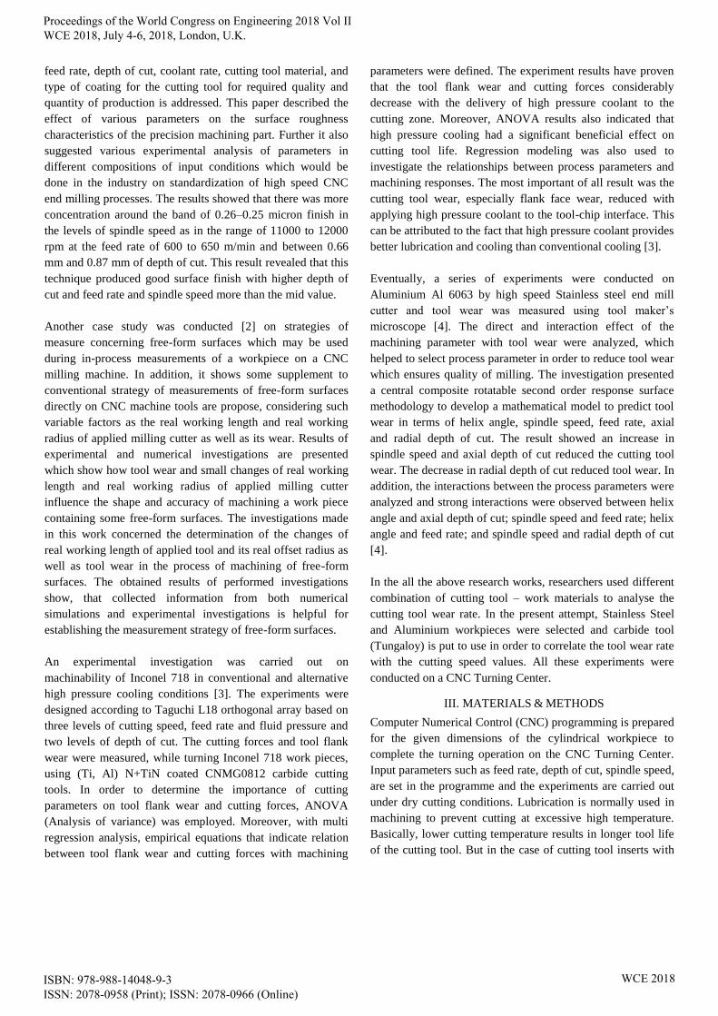
feed rate, depth of cut, coolant rate, cutting tool material, and
type of coating for the cutting tool for required quality and
quantity of production is addressed. This paper described the
effect of various parameters on the surface roughness
characteristics of the precision machining part. Further it also
suggested various experimental analysis of parameters in
different compositions of input conditions which would be
done in the industry on standardization of high speed CNC
end milling processes. The results showed that there was more
concentration around the band of 0.26–0.25 micron finish in
the levels of spindle speed as in the range of 11000 to 12000
rpm at the feed rate of 600 to 650 m/min and between 0.66
mm and 0.87 mm of depth of cut. This result revealed that this
technique produced good surface finish with higher depth of
cut and feed rate and spindle speed more than the mid value.
Another case study was conducted [2] on strategies of
measure concerning free-form surfaces which may be used
during in-process measurements of a workpiece on a CNC
milling machine. In addition, it shows some supplement to
conventional strategy of measurements of free-form surfaces
directly on CNC machine tools are propose, considering such
variable factors as the real working length and real working
radius of applied milling cutter as well as its wear. Results of
experimental and numerical investigations are presented
which show how tool wear and small changes of real working
length and real working radius of applied milling cutter
influence the shape and accuracy of machining a work piece
containing some free-form surfaces. The investigations made
in this work concerned the determination of the changes of
real working length of applied tool and its real offset radius as
well as tool wear in the process of machining of free-form
surfaces. The obtained results of performed investigations
show, that collected information from both numerical
simulations and experimental investigations is helpful for
establishing the measurement strategy of free-form surfaces.
An experimental investigation was carried out on
machinability of Inconel 718 in conventional and alternative
high pressure cooling conditions [3]. The experiments were
designed according to Taguchi L18 orthogonal array based on
three levels of cutting speed, feed rate and fluid pressure and
two levels of depth of cut. The cutting forces and tool flank
wear were measured, while turning Inconel 718 work pieces,
using (Ti, Al) N+TiN coated CNMG0812 carbide cutting
tools. In order to determine the importance of cutting
parameters on tool flank wear and cutting forces, ANOVA
(Analysis of variance) was employed. Moreover, with multi
regression analysis, empirical equations that indicate relation
between tool flank wear and cutting forces with machining
parameters were defined. The experiment results have proven
that the tool flank wear and cutting forces considerably
decrease with the delivery of high pressure coolant to the
cutting zone. Moreover, ANOVA results also indicated that
high pressure cooling had a significant beneficial effect on
cutting tool life. Regression modeling was also used to
investigate the relationships between process parameters and
machining responses. The most important of all result was the
cutting tool wear, especially flank face wear, reduced with
applying high pressure coolant to the tool-chip interface. This
can be attributed to the fact that high pressure coolant provides
better lubrication and cooling than conventional cooling [3].
Eventually, a series of experiments were conducted on
Aluminium Al 6063 by high speed Stainless steel end mill
cutter and tool wear was measured using tool maker’s
microscope [4]. The direct and interaction effect of the
machining parameter with tool wear were analyzed, which
helped to select process parameter in order to reduce tool wear
which ensures quality of milling. The investigation presented
a central composite rotatable second order response surface
methodology to develop a mathematical model to predict tool
wear in terms of helix angle, spindle speed, feed rate, axial
and radial depth of cut. The result showed an increase in
spindle speed and axial depth of cut reduced the cutting tool
wear. The decrease in radial depth of cut reduced tool wear. In
addition, the interactions between the process parameters were
analyzed and strong interactions were observed between helix
angle and axial depth of cut; spindle speed and feed rate; helix
angle and feed rate; and spindle speed and radial depth of cut
[4].
In the all the above research works, researchers used different
combination of cutting tool – work materials to analyse the
cutting tool wear rate. In the present attempt, Stainless Steel
and Aluminium workpieces were selected and carbide tool
(Tungaloy) is put to use in order to correlate the tool wear rate
with the cutting speed values. All these experiments were
conducted on a CNC Turning Center.
III. MATERIALS & METHODS
Computer Numerical Control (CNC) programming is prepared
for the given dimensions of the cylindrical workpiece to
complete the turning operation on the CNC Turning Center.
Input parameters such as feed rate, depth of cut, spindle speed,
are set in the programme and the experiments are carried out
under dry cutting conditions. Lubrication is normally used in
machining to prevent cutting at excessive high temperature.
Basically, lower cutting temperature results in longer tool life
of the cutting tool. But in the case of cutting tool inserts with
Proceedings of the World Congress on Engineering 2018 Vol II WCE 2018, July 4-6, 2018, London, U.K.
ISBN: 978-988-14048-9-3 ISSN: 2078-0958 (Print); ISSN: 2078-0966 (Online)
WCE 2018
TiN coating, the cutting tool insert will work better at high
temperature. Dry cutting is better than wet cutting for TiN
coating inserts under high speed cutting.
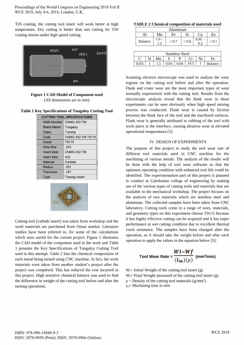
Figure 1 CAD Model of Component used
(All dimensions are in mm)
Table 1 Key Specifications of Tungaloy Cutting Tool
Cutting tool (carbide insert) was taken from workshop and the
work materials are purchased from Oman market. Literature
studies have been referred to, for some of the calculations
which were useful for the current project. Figure 1 illustrates
the CAD model of the component used in the work and Table
1 presents the Key Specifications of Tungaloy Cutting Tool
used in this attempt. Table 2 lists the chemical composition of
each metal being turned using CNC machine. In fact, the work
materials were taken from another student’s project after the
project was completed. This has reduced the cost incurred in
this project. High sensitive chemical balance was used to find
the difference in weight of the cutting tool before and after the
turning operations.
TABLE 2 Chemical composition of materials used
Aluminum
Al Mn Fe Si Cu Zn
Balance 1.0 –
1.5 < 0.7 < 0.6
0.05 –
0.2 < 0.1
Stainless Steel
C Si Mn S P Cr Ni Fe
0.03 1 1.5 0.04 0.04 10.5 1 Balance
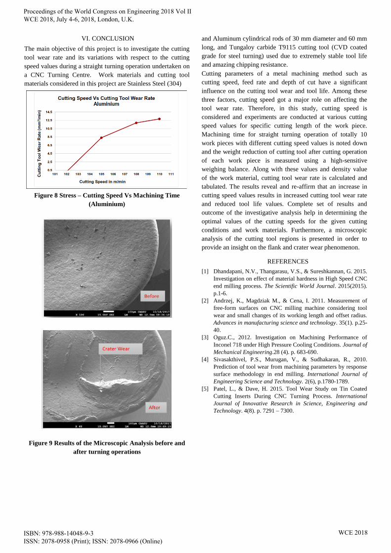
Scanning electron microscope was used to analyse the wear
regions on the cutting tool before and after the operation.
Flank and crater wear are the most important types of wear
normally experienced with the cutting tool. Results from the
microscopic analysis reveal that the flank wear in these
experiments can be seen obviously when high speed turning
process was conducted. Flank wear is caused by friction
between the flank face of the tool and the machined surfaces.
Flank wear is generally attributed to rubbing of the tool with
work piece at the interface, causing abrasive wear at elevated
operational temperatures [5].
IV. DESIGN OF EXPERIMENTS
The purpose of this project to study the tool wear rate of
different tool materials used in CNC machine for the
machining of various metals. The analysis of the results will
be done with the help of tool wear software so that the
optimum operating condition with enhanced tool life could be
identified. The experimentation part of this project is planned
to conduct at Caledonian college of engineering by making
use of the various types of cutting tools and materials that are
available in the mechanical workshop. The project focuses on
the analysis of two materials which are stainless steel and
aluminum. The collected samples have been taken from CNC
laboratory. Cutting tools come in a range of sizes, materials,
and geometry types on this experiment choose T9115 because
it has highly effective cutting can be acquired and it has super
performance at wet cutting condition due to excellent thermal
crack resistance. The samples have been changed after the
operation, so it should take the weight before and after each
operation to apply the values in the equation below [5]:
Tool Wear Rate = (mm3/min)
Wi= Initial Weight of the cutting tool insert (g)
Wf= Final Weight measured of the cutting tool insert (g)
ρ = Density of the cutting tool materials (g/mm3)
tm= Machining time in min
Proceedings of the World Congress on Engineering 2018 Vol II WCE 2018, July 4-6, 2018, London, U.K.
ISBN: 978-988-14048-9-3 ISSN: 2078-0958 (Print); ISSN: 2078-0966 (Online)
WCE 2018
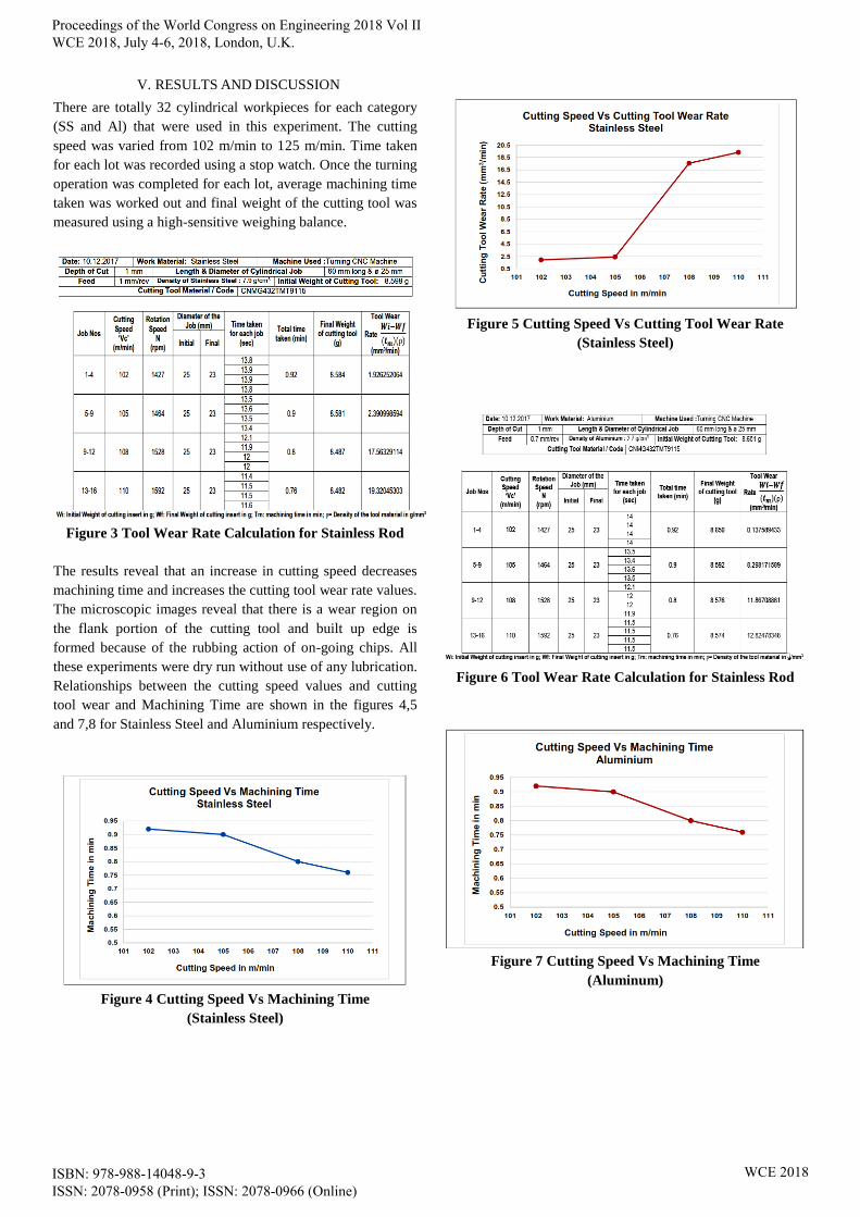
V. RESULTS AND DISCUSSION
There are totally 32 cylindrical workpieces for each category
(SS and Al) that were used in this experiment. The cutting
speed was varied from 102 m/min to 125 m/min. Time taken
for each lot was recorded using a stop watch. Once the turning
operation was completed for each lot, average machining time
taken was worked out and final weight of the cutting tool was
measured using a high-sensitive weighing balance.
Figure 3 Tool Wear Rate Calculation for Stainless Rod
The results reveal that an increase in cutting speed decreases
machining time and increases the cutting tool wear rate values.
The microscopic images reveal that there is a wear region on
the flank portion of the cutting tool and built up edge is
formed because of the rubbing action of on-going chips. All
these experiments were dry run without use of any lubrication.
Relationships between the cutting speed values and cutting
tool wear and Machining Time are shown in the figures 4,5
and 7,8 for Stainless Steel and Aluminium respectively.
Figure 4 Cutting Speed Vs Machining Time
(Stainless Steel)
Figure 5 Cutting Speed Vs Cutting Tool Wear Rate
(Stainless Steel)
Figure 6 Tool Wear Rate Calculation for Stainless Rod
Figure 7 Cutting Speed Vs Machining Time
(Aluminum)
Proceedings of the World Congress on Engineering 2018 Vol II WCE 2018, July 4-6, 2018, London, U.K.
ISBN: 978-988-14048-9-3 ISSN: 2078-0958 (Print); ISSN: 2078-0966 (Online)
WCE 2018
VI. CONCLUSION
The main objective of this project is to investigate the cutting
tool wear rate and its variations with respect to the cutting
speed values during a straight turning operation undertaken on
a CNC Turning Centre. Work materials and cutting tool
materials considered in this project are Stainless Steel (304)
Figure 8 Stress – Cutting Speed Vs Machining Time
(Aluminium)
Figure 9 Results of the Microscopic Analysis before and
after turning operations
and Aluminum cylindrical rods of 30 mm diameter and 60 mm
long, and Tungaloy carbide T9115 cutting tool (CVD coated
grade for steel turning) used due to extremely stable tool life
and amazing chipping resistance.
Cutting parameters of a metal machining method such as
cutting speed, feed rate and depth of cut have a significant
influence on the cutting tool wear and tool life. Among these
three factors, cutting speed got a major role on affecting the
tool wear rate. Therefore, in this study, cutting speed is
considered and experiments are conducted at various cutting
speed values for specific cutting length of the work piece.
Machining time for straight turning operation of totally 10
work pieces with different cutting speed values is noted down
and the weight reduction of cutting tool after cutting operation
of each work piece is measured using a high-sensitive
weighing balance. Along with these values and density value
of the work material, cutting tool wear rate is calculated and
tabulated. The results reveal and re-affirm that an increase in
cutting speed values results in increased cutting tool wear rate
and reduced tool life values. Complete set of results and
outcome of the investigative analysis help in determining the
optimal values of the cutting speeds for the given cutting
conditions and work materials. Furthermore, a microscopic
analysis of the cutting tool regions is presented in order to
provide an insight on the flank and crater wear phenomenon.
REFERENCES
[1] Dhandapani, N.V., Thangarasu, V.S., & Sureshkannan, G. 2015.
Investigation on effect of material hardness in High Speed CNC
end milling process. The Scientific World Journal. 2015(2015).
p.1-6.
[2] Andrzej, K., Magdziak M., & Cena, I. 2011. Measurement of
free-form surfaces on CNC milling machine considering tool
wear and small changes of its working length and offset radius.
Advances in manufacturing science and technology. 35(1). p.25-
40.
[3] Oguz.C., 2012. Investigation on Machining Performance of
Inconel 718 under High Pressure Cooling Conditions. Journal of
Mechanical Engineering.28 (4). p. 683-690.
[4] Sivasakthivel, P.S., Murugan, V., & Sudhakaran, R., 2010.
Prediction of tool wear from machining parameters by response
surface methodology in end milling. International Journal of
Engineering Science and Technology. 2(6), p.1780-1789.
[5] Patel, L., & Dave, H. 2015. Tool Wear Study on Tin Coated
Cutting Inserts During CNC Turning Process. International
Journal of Innovative Research in Science, Engineering and
Technology. 4(8). p. 7291 – 7300.
Proceedings of the World Congress on Engineering 2018 Vol II WCE 2018, July 4-6, 2018, London, U.K.
ISBN: 978-988-14048-9-3 ISSN: 2078-0958 (Print); ISSN: 2078-0966 (Online)
WCE 2018