Embed Size (px)
Citation preview

S3C44B0X RISC MICROPROCESSOR TOOLKIT & DEBUGGING
2-1
2 TOOLKIT & DEBUGGING
SETUP SMDK41100 ENVIRONMENTS
The evaluation environments for SMDK41100 are shown in Figure 2-1. Serial port(UART0) on SMDK41100 have to beconnected to COM port of Host PC. This can be used as console for monitoring and debugging SMDK41100.
If you have the emulator like as EmbeddedICE, you can use JTAG port on SMDK41100 as the interface for it.
DC power adapter can be used as input power of the SMDK41100 board. This input power regulated to 2.5V and3.3V for CPU and peripheral devices on SMDK41100 board.
Host PC(COM2)
LPT1 COM1RS232 Cable for Consol
DC Power7-9V
UART0 UART1 JTAG
4-6V DC Adapter
3.3V2.5V
S3C44B0X
SMDK41100
EmbeddedICEor MultiICE
Figure 2-1. Setup Environments for SMDK41100 Board

TOOLKIT & DEBUGGING S3C44B0X RISC MICROPROCESSOR
2-2
RS232C CABLE CONNECTION
The serial cable is made as in Figure 2-2. The other pins of the cable are not used. Please check the cable'sconnections again!
The UART0 and PC COM1 port has to be connected through this cable connection.
For Host(Female D-SUB9)
For SMDK41100(Male D-SUB9)
5
3
2
5
3
2
Figure 2-2. Serial Cable Connections for SMDK41100 Board

S3C44B0X RISC MICROPROCESSOR TOOLKIT & DEBUGGING
2-3
CONFIGURING THE HYPER TERMINAL (ON WINDOWS 95 OR NT)
To configure the Hyper Terminal, which is windows utility program for serial communications be given on windows 95or NT, please following steps:
1. Running the Hyper Terminal utility program.Window 95 or Windows NT start tool bar à Program à Accessories à Hyper Terminal Group à Double clickHyperterm.exe à Enter connection name à Select icon à Click OK.
2. Select COM port to communicate with SMDK41100 target board.Choose COM1 (or COM2) as the serial communication port à Click OK
3. Set the serial port properties. (See the Figure 2-3.)
— Bits per second: 115200 bps
— Data bits: 8 bits
— Stop bits: 1
— Flow control: None
Figure 2-3. Setting Port Properties

TOOLKIT & DEBUGGING S3C44B0X RISC MICROPROCESSOR
2-4
4. Select Properties menuFile à Properties.
5. Choose Setting Page (Figure 2-4)
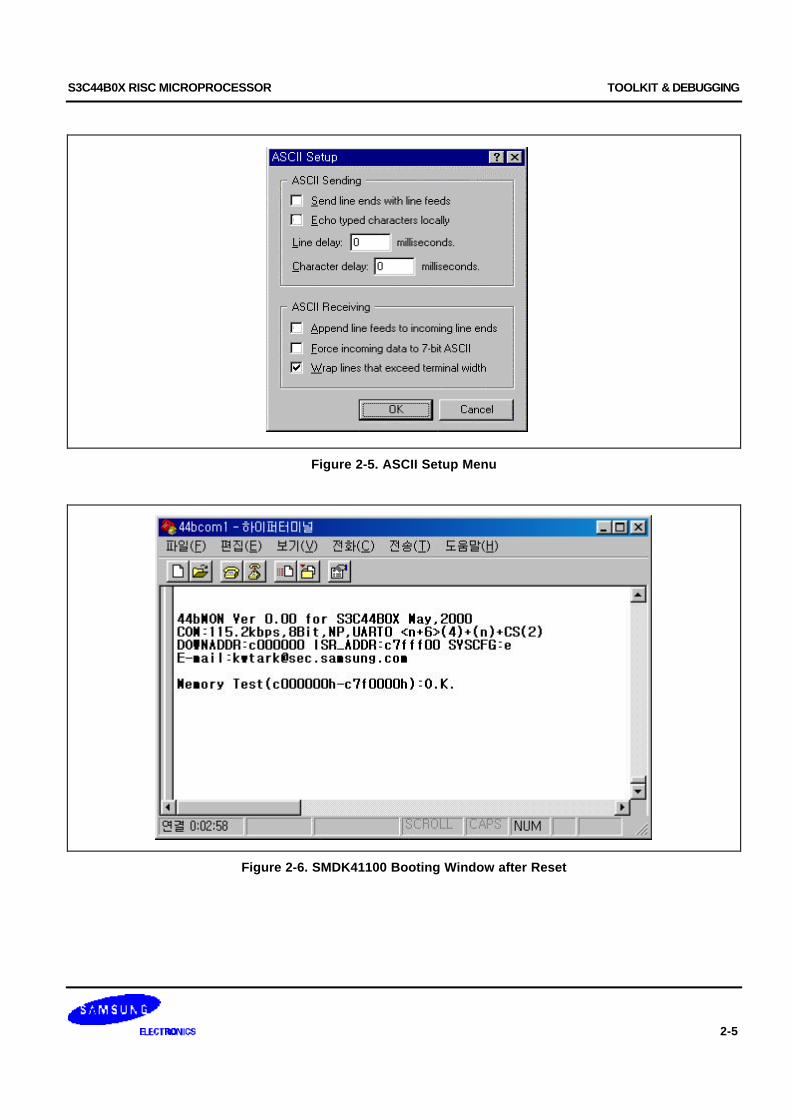
6. Click ASCII Setup button
7. Check ASCII Setup menus and set (Figure 2-5)
8. Re-connect Hyper-Terminal to run at new properties
— Disconnect: Call à Disconnect
— Connect: Call à Call
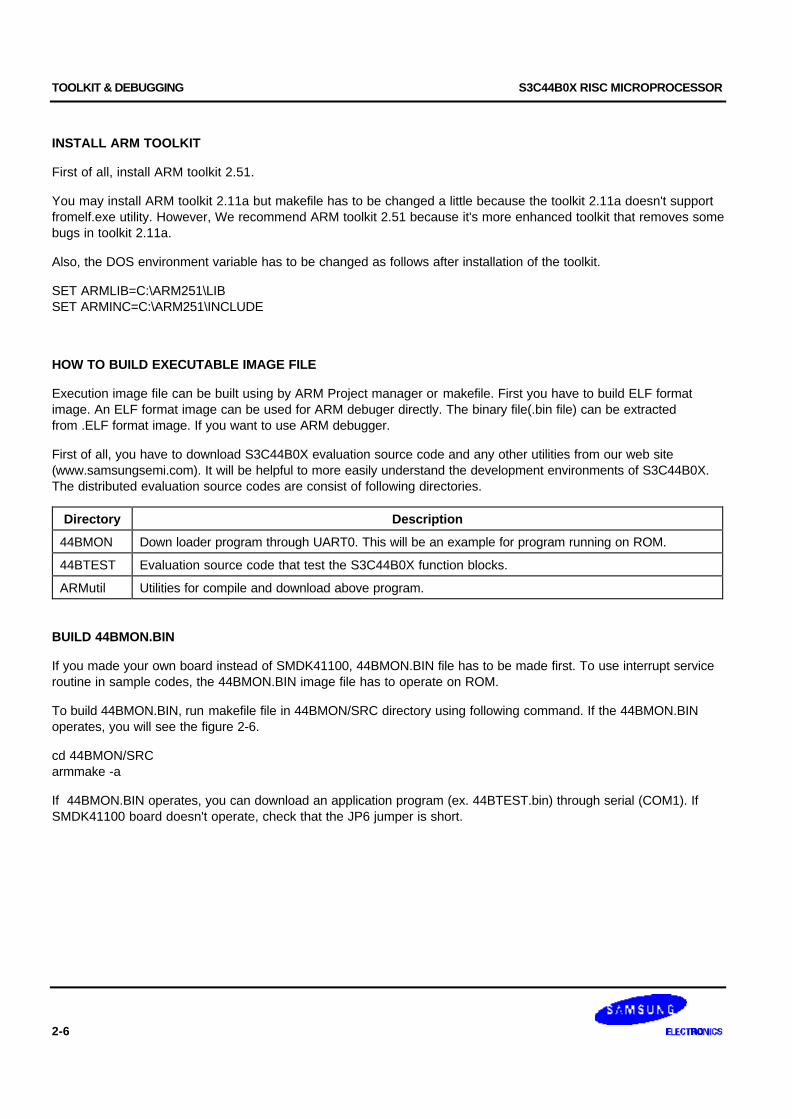
9. Power-On Reset or Push the reset button on SMDK41100 board
— Now, The diagnostic menu is showed on the Hyper-Terminal (Refer to Figure 2-6).
Figure 2-4. Choose Setting Page
S3C44B0X RISC MICROPROCESSOR TOOLKIT & DEBUGGING
2-5
Figure 2-5. ASCII Setup Menu
Figure 2-6. SMDK41100 Booting Window after Reset
TOOLKIT & DEBUGGING S3C44B0X RISC MICROPROCESSOR
2-6
INSTALL ARM TOOLKIT
First of all, install ARM toolkit 2.51.
You may install ARM toolkit 2.11a but makefile has to be changed a little because the toolkit 2.11a doesn't supportfromelf.exe utility. However, We recommend ARM toolkit 2.51 because it's more enhanced toolkit that removes somebugs in toolkit 2.11a.
Also, the DOS environment variable has to be changed as follows after installation of the toolkit.
SET ARMLIB=C:\ARM251\LIBSET ARMINC=C:\ARM251\INCLUDE
HOW TO BUILD EXECUTABLE IMAGE FILE
Execution image file can be built using by ARM Project manager or makefile. First you have to build ELF formatimage. An ELF format image can be used for ARM debuger directly. The binary file(.bin file) can be extractedfrom .ELF format image. If you want to use ARM debugger.
First of all, you have to download S3C44B0X evaluation source code and any other utilities from our web site(www.samsungsemi.com). It will be helpful to more easily understand the development environments of S3C44B0X.The distributed evaluation source codes are consist of following directories.
Directory Description
44BMON Down loader program through UART0. This will be an example for program running on ROM.
44BTEST Evaluation source code that test the S3C44B0X function blocks.
ARMutil Utilities for compile and download above program.
BUILD 44BMON.BIN
If you made your own board instead of SMDK41100, 44BMON.BIN file has to be made first. To use interrupt serviceroutine in sample codes, the 44BMON.BIN image file has to operate on ROM.
To build 44BMON.BIN, run makefile file in 44BMON/SRC directory using following command. If the 44BMON.BINoperates, you will see the figure 2-6.
cd 44BMON/SRCarmmake -a
If 44BMON.BIN operates, you can download an application program (ex. 44BTEST.bin) through serial (COM1). IfSMDK41100 board doesn't operate, check that the JP6 jumper is short.

S3C44B0X RISC MICROPROCESSOR TOOLKIT & DEBUGGING
2-7
BUILD 44BTEST.ELF
To build the sample source code, 44BTEST, run makefile file in 44BTEST/SRC directory using following command.cd 44BTEST/SRCarmmake -a
After build, 44BTEST.ELF and 44BTEST.BIN image files will be seen in 44BTEST/BIN directory. The 44BTEST.ELFfile is used for ARM debugger.
The 44BTEST.BIN file is used for serial downloading with 44BMON.

TOOLKIT & DEBUGGING S3C44B0X RISC MICROPROCESSOR
2-8
EXECUTE 44BTEST WITHOUT MDS (EMBEDDED ICE, MULTI ICE OR JEENI )
First, 44BMON has to operate on ROM. 44BMON will be ready to receive 44BTEST.BIN. 44BMON will be launch44BTEST.BIN after receiving 44BTEST.BIN.
To download 44BTEST.BIN, Type following commands. Wkcom2.exe will transmit file size and checksum togetherwith .BIN file.
wkcom2 44BTEST.bin /1 /d:1
/1: com1 port is used.
/d:<n> : baud rate=115200 / <n>
After download, you can test S3C44B0X functional units and see figure 2-7
Figure 2-7. 44BTEST Execution After Download Using UART0
S3C44B0X RISC MICROPROCESSOR TOOLKIT & DEBUGGING
2-9
HOW TO USE ARM DEBUGGER WITH MDS (EMBEDDED ICE, MULTI ICE OR JEENI )
If you have built 44BTEST program without any error, you can find 44BTEST.ELF in 44BTEST/BIN directory. Thegenerated image file will be downloaded to SDRAM/DRAM memory on the SMDK41100 target board by ARMdebugger through MDS, such as EmbeddedICE, MultiICE, JEENI an so on. Next, you can start to debug thedownloaded image using ADW( ARM Debugger for Window ).
PREPARING EMBEDDED ICE
1. EmbeddedICE will be connected through JTAG port on the board. Connect all cables properly by each MDSmanual. Open JP6 on SMDK41100 board to use JTAG port.
Reset the SMDK41100 board and the EmbeddedICE interface unit.
Reset SMDK41100 board (Press reset switch) → Reset EmbeddedICE unit (Press red switch)
2. Start ARM Debugger using ARM debugger icon
Also, you can start it at DOS command window as you type adw 44BTEST.elf in there.
3. When ARM Debugger is started, it will load the image code to Armulator. (The Armulator is software emulator forARM7T CPU )
If you ever used ARM Debugger as a remote debugger, Remote Debugger warning message dialog box will bedisplayed. If the remote debugger option is correct, then select Yes, otherwise, select No.
CONFIGURING ARM DEBUGGER FOR EMBEDDED ICE
In order to access a remote target, you should configure ARM Debugger for Windows (ADW) rather thanARMulator. The EmbeddedICE interface unit must also be configured for the ARM core in the target system
The ARM7TDMI core is contained in the S3C44B0X on the SMDK41100 board. ARM7TDMI macro cell includes theARM7 core with Thumb, debug extensions, and the EmbeddedICE macro cell.
To configure ARM Debugger using the EmbeddedICE interface, follow the below steps:
1. Select Configure Debugger from the Options menu.
Options -> Configure Debugger
2. Debugger Configuration dialog box is displayed (Figure 2-8). When you select Target page, there are twoTarget Environment available as follows.
— ARMulator: lets you execute the ARM program without any physical ARM hardware by simulating ARMinstructions in software.
— Remote_A: connects the ARM debugger directly to the target board or to an EmbeddedICE unit attached tothe target.
3. Select Remote_A from target environments, and click Configure.
4. Configure Angel Remote Configuration dialog box(Figure 2-9).
— Remote Connection: select your host and EmbeddedICE communication port configuration.
— Select Ports and Serial Line Speed.

TOOLKIT & DEBUGGING S3C44B0X RISC MICROPROCESSOR
2-10
5. Select Debugger page from Debugger Configuration dialog box (Figure 2-10 ) and configure it.
— Endian: little (If the big endian is used, Endian: big has to be selected.)
6. Select Memory Maps page from Debugger Configuration dialog box and configure it.
— No Map File
7. If you click the OK button on Debugger Configuration dialog box, the debugger will be restarted. The restartingdialog box is displayed and numbers are rapidly changing, indicating that it is reading and writing to target. Thismeans that the executable image file is downloaded to the SDRAM/DRAM code area.
This configuration is done once at first. In the next time, this configuration is not needed because the setting wassaved.
Figure 2-8. Debugger Configuration: Target Page

S3C44B0X RISC MICROPROCESSOR TOOLKIT & DEBUGGING
2-11
Figure 2-9. Angel Remote Configuration
Figure 2-10. Debugger Configuration: Debugger Page

TOOLKIT & DEBUGGING S3C44B0X RISC MICROPROCESSOR
2-12
EXECUTING 44BTEST.ELF USING EMBEDDED ICE
1. Initialize debugger internal variables. After a download, several windows are displayed, such as Executionwindow, Console window, and Command window. In Command window, you must initialize the debugger internalvariables, "$semihosting_enabled" and "$vector_catch", by entering the following command:
let $vector_catch=0x00let $semihosting_enabled=0x00let psr=%if_SVC32
Or, you can initialize these variables as follows:
First, create a text file named "armsd.ini", which includes the commands described above. Then, enter thefollowing command in the Command window (Figure 2-11):
obey c:\armutil\armsd.ini
For more information about these steps, please refer to "ARM Software Development Toolkit User's Guide".
Figure 2-11. ARM Debugger Window(ADW): Command Window
3. Set breakpoint at Main in 44BTEST.c as followsbreak Main
4. Execute the program by clicking Execute menu→Go. The program execution will stop at Main( ).
5. Now, The downloaded image file will be run on SDRAM/DRAM area. 44BTEST program running status can bemonitored on the current Hyper-Terminal.

S3C44B0X RISC MICROPROCESSOR TOOLKIT & DEBUGGING
2-13
DEBUGGING DOWNLOAD IMAGE IN ADW
Stepping Through The Program
To step through the program execution flow, you can select one of the following three options:
— Step: advances the program to the next line of code that is displayed in the execution window.
— Step Into: advances the program to the next line of code that follows all function calls. If the code is in a calledfunction, the function source is displayed in the Execution window and the current code.
— Step Out: advances the program from the current function to the point from which it was called Immediately afterthe function call. The appropriate line of code is displayed in the Execution window.
Setting A Break Point
A breakpoint is the point you set in the program code where the ARM debugger will halt the program operation.When you set a breakpoint, it appears as a red marker on the left side of the window.
To set a simple breakpoint on a line of code, follow these steps:
1. Double-click the line where you want to place the break, or choose Toggle Breakpoint from the Execute menu.The Set or Edit Breakpoint dialog box is displayed.
2. Set the count to the required value or expression. (The program stops only when this expression is correct).
To set a breakpoint on a line of code within a particular program function:
1. Display a list of function names by selecting Function Names from View menu.
2. Double-click the function name you want to open. A new source window is displayed containing the functionsource.
3. Double-click the line where the breakpoint is to be placed, or choose Toggle Breakpoint from the Execute menu.The Set or Edit Breakpoint dialog box appears.
4. Set the count to the required value or expression. (The program stops only when this expression is correct).
Setting A Watch Point
A watch point halts a program when the value of a specified register or a variable changes is set to a specificnumber.
To set a watch point, follow these steps :
1. Display a list of registers, variables, and memory locations you want to watch by selecting the Registers,Variables, and Memory options from the View menu.
2. Click the register, variable, or memory area in which you want to set the watchpoint. Then choose Set or EditWatchpoint from the Execute menu.
3. Enter a Target Value in the Set or Edit Watchpoint dialog box. Program operation will stop when the variablereaches the specified target value.

TOOLKIT & DEBUGGING S3C44B0X RISC MICROPROCESSOR
2-14
VIEWING VARIABLES, REGISTERS, AND MEMORY
You can view and edit the value of variables, registers, and memory by choosing the related heading from the Viewmenu:
— Variables: for global and local variables.
— Registers: for the current mode and for each of the six register view modes.
— Memory: for the memory area defined by the address you enter.
DISPLAYING THE CODE INTERLEAVED WITH THE DISASSEMBLY
If you want to display the source code interleaved with disassembly, choose Toggle Interleaving on the Optionsmenu. This command toggles between Displaying Source Only and Displaying Source Interleaved WithDisassembly. When the source code is shown interleaved with disassembly, machine instructions appear in a lightergray color.
For additional information about ARM Debugger, please refer to ARM Software Development Toolkit User's Guide.

S3C44B0X RISC MICROPROCESSOR TOOLKIT & DEBUGGING
2-15
WRITE IMAGE TO FLASH MEMORY(AM29LV800BB)
OPEN THE JP3 IN SMDK41100
The SMDK41100 shares nGCS0 signal for Flash memory(U16) and EEPROMs(U18, U19), so users connect the JP3pins to connect the nGCS0 signal to Flash ROM and remove the EEPROM(U18, U19).
NOTE: Flash memory should be unprotected before soldering on SMDK41100.
RUNNING ICE(MULTI-ICE, EMBEDDED ICE, JEENI OR OPEN-ICE)
Please refer to page 2-9.
NOTE: If there is no ICE, you should program 44bmon.bin in the flash memory with a ROM writer. And, execute the 44btest.bin using wkcom2.exe(please refer to the chapter, ‘EXECUTE 44BTEST WITHOUT MDS (EMBEDDED ICE,Multi ICE or JEENI )’. After 44btest.bin is being executed, please refer to the page 2-19, ’EXECUTION WRITE FLASH PROGRAM’.

TOOLKIT & DEBUGGING S3C44B0X RISC MICROPROCESSOR
2-16
OBEYING NOROM.INI
Obeying the norom.ini in 44BTEST.zip

S3C44B0X RISC MICROPROCESSOR TOOLKIT & DEBUGGING
2-17
LOADING 44BTEST.ELF
Load the 44btest.elf file in BIN directory

TOOLKIT & DEBUGGING S3C44B0X RISC MICROPROCESSOR
2-18
EXECUTION 44BTEST.ELF
Execute 44btest code with Go command

S3C44B0X RISC MICROPROCESSOR TOOLKIT & DEBUGGING
2-19
EXECUTION WRITE FLASH PROGRAM
1. Select " 37. Write flash " item in Hyper terminal
2. Select the type of memory– This program supports AM29LV800BB(AMD) only.
TOOLKIT & DEBUGGING S3C44B0X RISC MICROPROCESSOR
2-20
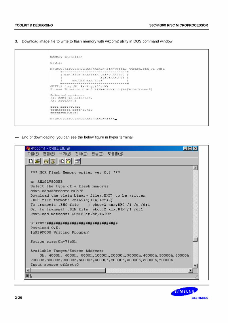
3. Download image file to write to flash memory with wkcom2 utility in DOS command window.
— End of downloading, you can see the below figure in hyper terminal.

S3C44B0X RISC MICROPROCESSOR TOOLKIT & DEBUGGING
2-21
4. Write source-offset and target-offset repeatedly until source size.(Below example shows how to setting source-offset and target-offset, in case of the size of imageare 0x76e0 bytes.)
— Write source offset ‘0h’ and write target address ‘0h’, and then write ‘y’.

TOOLKIT & DEBUGGING S3C44B0X RISC MICROPROCESSOR
2-22
— Write source offset ‘4000h’ and write target address ‘4000h’, and then write ‘y’.

S3C44B0X RISC MICROPROCESSOR TOOLKIT & DEBUGGING
2-23
— Write source offset ‘6000h’ and write target address ‘6000h’, and then write ‘y’.

TOOLKIT & DEBUGGING S3C44B0X RISC MICROPROCESSOR
2-24
— Write source offset ‘8000h’ and write target address ‘8000h’, and then write ‘n’.
5. Reset SMDK41100 board.

S3C44B0X RISC MICROPROCESSOR TOOLKIT & DEBUGGING
2-25
MULTI-ICE CHECKPOINTS
1. Error messages
First of all, Please refer to the Multi-ICE user's guide 3.10 Error Messages. If you can't solve the problem althoughyou applied the instructions in the user's guide, please apply the 'Force 4-bit access" option.
2. Multi-ICE current consumption problem
Multi-ICE draws the Multi-ICE operating current from a target board. The current is about 130mA at 3.3V. If the targetboard can't supply the 130mA, the external power supply must be used for supplying the current to Multi-ICE. In thiscase, the J3 of the 20-way to 14-way adapter is used to supply external power to Multi-ICE.
3. nTRST, TMS,TCK,TDI pin connections
TMS,TCK,TDI pin must be pulled-up with 10K registers. If the ICE is not used when development is completed,nTRST must be 'L' level at least during reset.
4. nSRST pin in Multi-ICE isn't supported in SMDK41100 demo board.
Because the SMDK41100 demo board reset circuit is driven by 74LV14, nSRST will not operates properly. But, It'snot important to use Multi-ICE. Only restrictions is that you can't reset the board at a remote place.

TOOLKIT & DEBUGGING S3C44B0X RISC MICROPROCESSOR
2-26
TRANSLATING MAKEFILE FOR ADS 1.0 FROM SDT 2.50
This document explains about only translating an old makefile for SDT 2.50 to a new makefile for ADS 1.0. If youhave used SDT 2.50, it's recommended that you should read the document (ADS, Getting Started, ARM DUI0064A)about the difference between SDT 2.50 and ADS 1.0.
THE REMOVED OR CHANGED ITEMS FROM MAKEFILE FOR SDT 2.50
1. ARMLINK option— first: the path of an object file isn't needed.
2. ARMASM option— cpu : should be changed as -cpu ARM7TDMI— apcs: should be changed to -apcs /noswst
3. Compiler option— fc : should be removed.— zpz0 : should be removed. This is not needed anymore.— apcs : should be changed to -apcs /noswst— processor : should be removed.— arch : should be removed.— cpu : should be added as -cpu ARM7TDMI
4. fromelf.exe— nozeropad: should be removed. This is not needed anymore.— output : command line style should be changed using -output option as follows; fromelf -nodebug -bin -output $(BIN)\$(PRJ).bin $(BIN)\$(PRJ).elf
THE OTHER ITEMS CHANGED FOR ADS 1.0
1. ammake.exeThe armmake.exe isn't supplied with ADS 1.0. So, use your own make utility (nmake.exe, make.exe,pmake.exe, or armmake.exe in SDT 2.50).
2. embedded library.There is no separate embedded library in ADS 1.0. All library in ADS 1.0 is made for embedded application.But, the library must be initialized using __rt_lib_init() function. If you don't use __rt_lib_init(), the C librarydoesn't work well.
3. There is no tasm.exe. The tasm.exe is merged into armasm.exe

S3C44B0X RISC MICROPROCESSOR TOOLKIT & DEBUGGING
2-27
THE EXAMPLE OF MAKEFILE FOR ADS 1.0
Pay attention to the bold type font items. The items are different parts with makefile for SDT 2.50.
#### File Definition ####PRJ = 44btestINIT= 44binitAM1 = 44blib_aCM1 = 44blibCM2 = lcdCM3 = glibCM4 = lcdlibCM5 = extdmaCM6 = idleCM7 = flashCM8 = am29f800CM9 = nwait
#### Destination path Definition ####SRC=.INC=..\incOBJ=..\objERR=..\errBIN=..\bin
#### ARM tool Definition ####ARMLINK= armlinkARMASM = armasmARMCC = armcc
#### Option Definition ####LFLAGS = -ro-base 0xc000000 -rw-base 0x0c040000 -elf $(BIN)\list.lst\ -first $(INIT).o(Init)AFLAGS = -li -apcs /noswst -cpu ARM7TDMICFLAGS = -c -g+ -li -apcs /noswst -cpu ARM7TDMI
#If you doesn't debug,use following CFLAGS for more faster operation.#The default optimization method is -O2 when -g- is used.#CFLAGS = -c -g- -li -apcs /noswst/nofp -cpu ARM7TDMI
#### Object combine Definition ####OBJS= $(OBJ)\$(PRJ).o $(OBJ)\$(INIT).o $(OBJ)\$(CM1).o\
$(OBJ)\$(CM2).o $(OBJ)\$(CM3).o $(OBJ)\$(CM4).o\$(OBJ)\$(CM5).o $(OBJ)\$(CM6).o $(OBJ)\$(CM7).o\$(OBJ)\$(CM8).o $(OBJ)\$(CM9).o $(OBJ)\$(AM1).o
all: $(PRJ).elf

TOOLKIT & DEBUGGING S3C44B0X RISC MICROPROCESSOR
2-28
clean:del $(OBJ)\*.odel $(BIN)\*.bindel $(BIN)\*.elfdel $(ERR)\*.err
$(PRJ).elf: $(OBJS)$(ARMLINK) $(LFLAGS) -o $(BIN)\$(PRJ).elf $(OBJS)fromelf -nodebug -bin -output $(BIN)\$(PRJ).bin $(BIN)\$(PRJ).elfcopy ..\bin\$(PRJ).bin .copy ..\bin\$(PRJ).elf .
$(OBJ)\$(PRJ).o : $(SRC)\$(PRJ).c $(INC)\44b.h $(INC)\44blib.h makefile$(ARMCC) $(CFLAGS) $(SRC)\$(PRJ).c -o $(OBJ)\$(PRJ).o\
-Errors $(ERR)\$(PRJ).err$(OBJ)\$(INIT).o: $(SRC)\$(INIT).s makefile
$(ARMASM) $(AFLAGS) $(SRC)\$(INIT).s -o $(OBJ)\$(INIT).o\ -Errors $(ERR)\$(INIT).err$(OBJ)\$(AM1).o: $(SRC)\$(AM1).s makefile
$(ARMASM) $(AFLAGS) $(SRC)\$(AM1).s -o $(OBJ)\$(AM1).o\ -Errors $(ERR)\$(AM1).err$(OBJ)\$(CM1).o: $(SRC)\$(CM1).c $(INC)\44b.h $(INC)\44blib.h makefile
$(ARMCC) $(CFLAGS) $(SRC)\$(CM1).c -o $(OBJ)\$(CM1).o\ -Errors $(ERR)\$(CM1).err
.
.
.
$(OBJ)\$(CM9).o: $(SRC)\$(CM9).c $(INC)\44b.h $(INC)\44blib.h makefile$(ARMCC) $(CFLAGS) $(SRC)\$(CM9).c -o $(OBJ)\$(CM9).o\
-Errors $(ERR)\$(CM9).err


![Debugging with gdb · Debugging Data Race Conditions: Section 12.2 [Data Race Detection], page 171. Debugging OpenMP*: Section 12.4 [OpenMP* Debugging], page 177. Extended recording](https://img.pdfslide.net/doc/110x75/5f0b5c707e708231d4302334/debugging-with-gdb-debugging-data-race-conditions-section-122-data-race-detection.jpg)