Embed Size (px)
Citation preview
HYDRAULIC I�STALLATIO�
TOOLS A�D SUPPLIES �EEDED FOR HYDRAULIC I�STALLATIO�: -Minimum of 7 quarts of ISO 46 hydraulic fluid or its equivalent. If not available, Dextron III may be
used.
-Amount of fluid needed depends on length of hose run. Tank requires approximately 7 quarts of oil.
- In addition you will need approximately 1 pint of fluid for each additional 10 feet of hose run.
-1 Crescent wrenches or (1) 11/16”open-end wrench.
-Air to blow out hydro lines
-1/8” and 6mm Allen wrench
-3/8” wrench (open or box)
-Funnel with filter screen. The filter screen should be approx. 60 micron. Funnel end should be no larger
in diameter than the oil fill opening
-Shop-Vac to suck string through the hydraulic chase
I�STALLATIO� OF HYDRAULIC POWER PACK
1. Pull hydraulic lines into the chase taking care to keep lines
clean. A small amount of dirt will cause the unit to not
operate properly. This is the most critical part of the install.
It is imperative that the hoses be kept clean. Optional bolts
(part number M3857) with holes in them are available from
Coverstar for pulling hose. (see picture at right) If the run is
long or with bends, use a lubricant. Electrician’s lubricant for
pulling wires, automatic transmission fluid or hydraulic fluid
works well. For additional information on pulling hoses see
Addendum A
2. The hoses will be shipped from the factory with the fittings
already crimped onto the ends of the hose and cut to match the
length of the hose that was ordered. You will not need to
cut the hoses in the field.
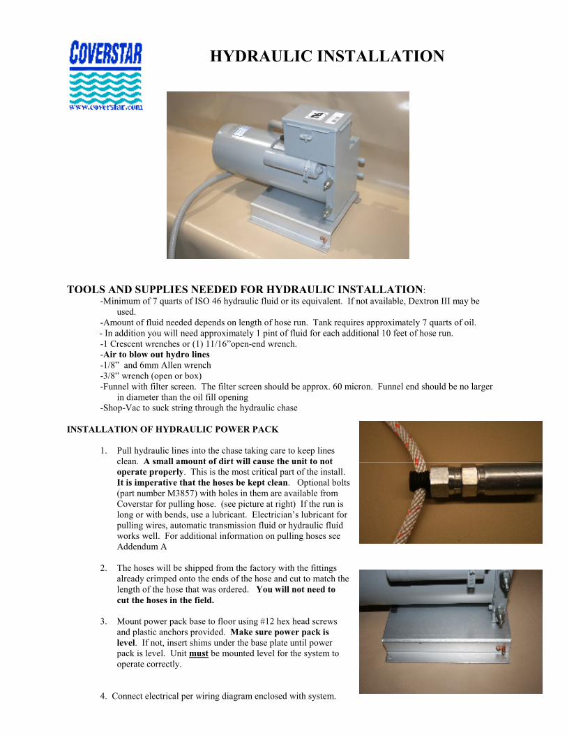
3. Mount power pack base to floor using #12 hex head screws
and plastic anchors provided. Make sure power pack is
level. If not, insert shims under the base plate until power
pack is level. Unit must be mounted level for the system to
operate correctly.
4. Connect electrical per wiring diagram enclosed with system.
Bond both mechanism and powerpack.
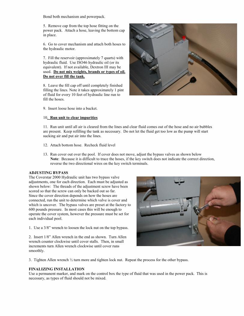
5. Remove cap from the top hose fitting on the
power pack. Attach a hose, leaving the bottom cap
in place.
6. Go to cover mechanism and attach both hoses to
the hydraulic motor.
7. Fill the reservoir (approximately 7 quarts) with
hydraulic fluid. Use ISO46 hydraulic oil (or its
equivalent). If not available, Dextron III may be
used. Do not mix weights, brands or types of oil.
Do not over fill the tank.
8. Leave the fill cap off until completely finished
filling the lines. Note it takes approximately 1 pint
of fluid for every 10 feet of hydraulic line run to
fill the hoses.
9. Insert loose hose into a bucket.
10. Run unit to clear impurities
11. Run unit until all air is cleared from the lines and clear fluid comes out of the hose and no air bubbles
are present. Keep refilling the tank as necessary. Do not let the fluid get too low as the pump will start
sucking air and put air into the lines.
12. Attach bottom hose. Recheck fluid level
13. Run cover out over the pool. If cover does not move, adjust the bypass valves as shown below
�ote: Because it is difficult to trace the hoses, if the key switch does not indicate the correct direction,
reverse the two directional wires on the key switch terminals.
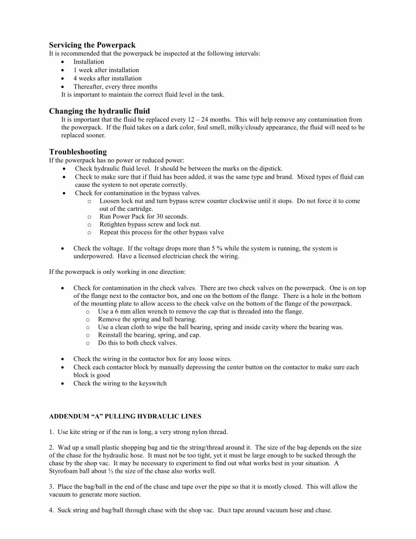
ADJUSTI�G BYPASS
The Coverstar 2000 Hydraulic unit has two bypass valve
adjustments, one for each direction. Each must be adjusted as
shown below: The threads of the adjustment screw have been
scored so that the screw can only be backed out so far.
Since the cover direction depends on how the hoses are
connected, run the unit to determine which valve is cover and
which is uncover. The bypass valves are preset at the factory to
600 pounds pressure. In most cases this will be enough to
operate the cover system, however the pressure must be set for
each individual pool.
1. Use a 3/8” wrench to loosen the lock nut on the top bypass.
2. Insert 1/8” Allen wrench in the end as shown. Turn Allen
wrench counter clockwise until cover stalls. Then, in small
increments turn Allen wrench clockwise until cover runs
smoothly.
3. Tighten Allen wrench ½ turn more and tighten lock nut. Repeat the process for the other bypass.
FI�ALIZI�G I�STALLATIO�
Use a permanent marker, and mark on the control box the type of fluid that was used in the power pack. This is
necessary, as types of fluid should not be mixed.
Servicing the Powerpack It is recommended that the powerpack be inspected at the following intervals:
• Installation
• 1 week after installation
• 4 weeks after installation
• Thereafter, every three months
It is important to maintain the correct fluid level in the tank.
Changing the hydraulic fluid It is important that the fluid be replaced every 12 – 24 months. This will help remove any contamination from
the powerpack. If the fluid takes on a dark color, foul smell, milky/cloudy appearance, the fluid will need to be
replaced sooner.
Troubleshooting If the powerpack has no power or reduced power:
• Check hydraulic fluid level. It should be between the marks on the dipstick.
• Check to make sure that if fluid has been added, it was the same type and brand. Mixed types of fluid can
cause the system to not operate correctly.
• Check for contamination in the bypass valves.
o Loosen lock nut and turn bypass screw counter clockwise until it stops. Do not force it to come
out of the cartridge.
o Run Power Pack for 30 seconds.
o Retighten bypass screw and lock nut.
o Repeat this process for the other bypass valve
• Check the voltage. If the voltage drops more than 5 % while the system is running, the system is
underpowered. Have a licensed electrician check the wiring.
If the powerpack is only working in one direction:
• Check for contamination in the check valves. There are two check valves on the powerpack. One is on top
of the flange next to the contactor box, and one on the bottom of the flange. There is a hole in the bottom
of the mounting plate to allow access to the check valve on the bottom of the flange of the powerpack.
o Use a 6 mm allen wrench to remove the cap that is threaded into the flange.
o Remove the spring and ball bearing.
o Use a clean cloth to wipe the ball bearing, spring and inside cavity where the bearing was.
o Reinstall the bearing, spring, and cap.
o Do this to both check valves.
• Check the wiring in the contactor box for any loose wires.
• Check each contactor block by manually depressing the center button on the contactor to make sure each
block is good
• Check the wiring to the keyswitch
ADDE�DUM “A” PULLI�G HYDRAULIC LI�ES
1. Use kite string or if the run is long, a very strong nylon thread.
2. Wad up a small plastic shopping bag and tie the string/thread around it. The size of the bag depends on the size
of the chase for the hydraulic hose. It must not be too tight, yet it must be large enough to be sucked through the
chase by the shop vac. It may be necessary to experiment to find out what works best in your situation. A
Styrofoam ball about ½ the size of the chase also works well.
3. Place the bag/ball in the end of the chase and tape over the pipe so that it is mostly closed. This will allow the
vacuum to generate more suction.
4. Suck string and bag/ball through chase with the shop vac. Duct tape around vacuum hose and chase.
5. Attach rope to the string and pull it through the chase.
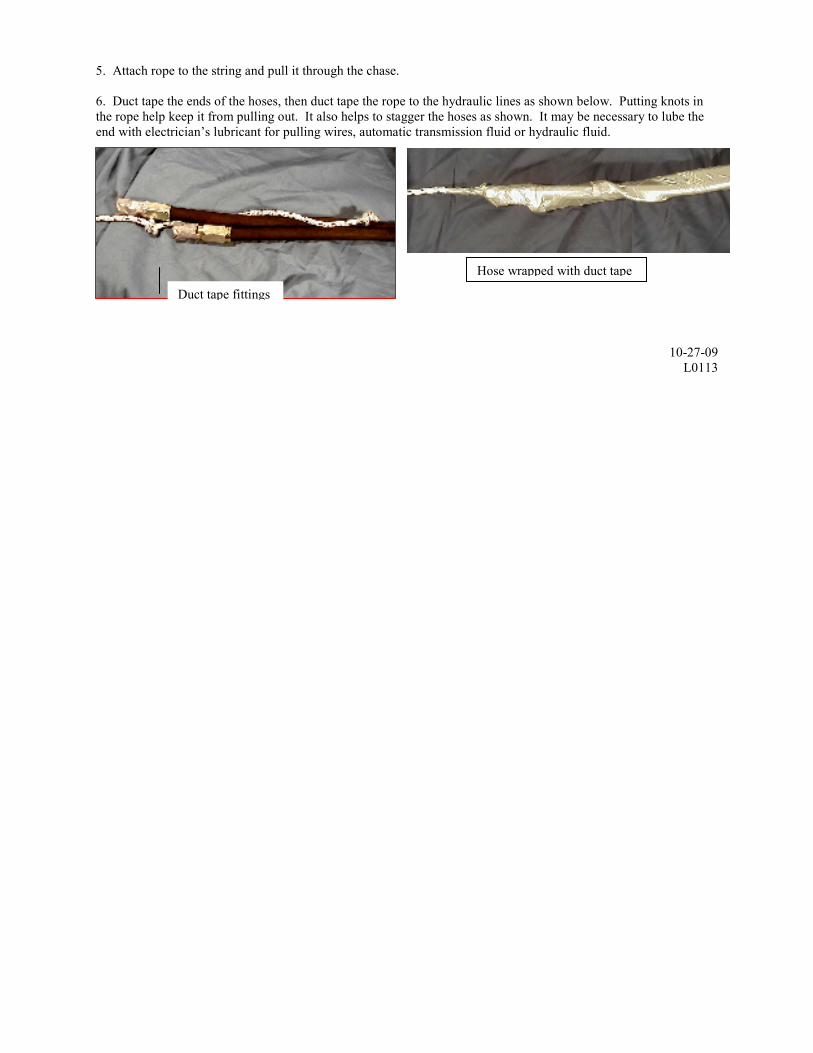
6. Duct tape the ends of the hoses, then duct tape the rope to the hydraulic lines as shown below. Putting knots in
the rope help keep it from pulling out. It also helps to stagger the hoses as shown. It may be necessary to lube the
end with electrician’s lubricant for pulling wires, automatic transmission fluid or hydraulic fluid.
10-27-09
L0113
Duct tape fittings
Hose wrapped with duct tape