Embed Size (px)
Citation preview

-1-02/2018
Top Bender® TB50® ClassicRotary Draw Bender for Pipe, Tube and Profile Bending
Operator’s Manual
WARNING!BEFORE USE, BE SURE EVERYONE USING THIS MACHINE READS AND
THOROUGHLY UNDERSTANDS ALL SAFETY AND OPERATING INSTRUCTIONS IN THIS MANUAL
Model TB50 Classic __________________ Serial # __________________________

-2- 02/2018
TB50® Classic Rotary BenderPipe, tube and profile bending machine
Congratulations on your purchase of an Ercolina® bending machine from CML USA, Inc. Ercolina® machines are designed and manufactured to deliver years of trouble-free bending performance. Please take a moment to complete and mail the warranty registration card. Doing so validates machine warranty period and ensures prompt service if needed. Thank you for selecting products from CML USA, Inc. Ercolina®.
Table of Contents
Terms and Conditions of sale 3Important safety instructions 4Special Instructions 5Before you begin and general identification 6TB50® features and specifications 7Wiring instructions and general assembly and setup 8Bending terminology and material selection 9Mounting tooling and selecting bend speed 10-11Ercolina® rotary draw tie bar assembly 12-13Bender programming 14-15Bending troubleshooting 16Display errors, accessories and maintenance 17Voltage troubleshooting, voltage test readings 18Grounding and wiring schematics 19-20Material length required for rotary bends in pipe (tube and pipe information) 21Conversion Tables - mm to inches and inches to mm 22Minimum distance between bends by center line radius, pipe and tube kits 23Ercolina® tube, pipe, profile benders and angle rolls 24-25
_____________________________________________________CML USA Ercolina® reserves the right to make improvements and
modifications to design without prior notice._____________________________________________________

-3-02/2018
TERMS AND CONDITIONS OF SALE 1. Definitions. As used herein, the term “Quotation” means these terms and conditions and all specifications, blueprints, drawings and data attached hereto or supplied by CML USA, Inc. (“CML”) hereunder; the term “End-User” means the ultimate user of the Goods; the term “Dealer” means an independent contractor of CML whom purchased the Goods from CML to sell to the End-User; and the term “Goods” means the goods, equipment, products, parts, services, labor, or other items or work provided for under this Quotation.
2. Mere Price Quotation. This Quotation is a mere price quotation and does not constitute an offer or contractual agreement for the sale of Goods between CML and the End-User. The End-User shall have no claim whatsoever against CML based on this Quotation. CML generally sells Goods only to Dealers, who sell Goods to End-Users. Any contractual agreement for the sale of Goods between CML and the End-User must be in writing and signed by CML’s president. Prices, specifications and lead times provided in the Quotation are subject to change (without notice) prior to the time of actual sale of the Goods.
3. Terms of Quotation. This Quotation relates only to the specifically quoted Goods. The End-User and CML acknowledge and agree the terms and conditions hereof supersede and reject all other oral or written communications regarding the subject matter hereof. The terms and conditions hereof may be amended, altered or changed only through a written document signed by the End-User and CML’s president.
THE FOLLOWING (OR SUBSTANTIALLY SIMILAR) PROVISIONS SHALL ONLY APPLY IN THE EVENT CML IN FACT PRODUCES OR PROVIDES ANY GOODS OR SAMPLES FOR OR TO THE END-USER:
4. End-User’s Materials. All materials required by CML to test the operation of the Goods shall be furnished by the End-User (at its sole cost and expense). All materials and equipment furnished by the End-User for the construction, remodeling, or testing of Goods (or for any other purpose) shall be delivered to CML at no cost to CML, FOB CML’s warehouse floor. The End-User shall bear the risk and cost of returning all such materials and equipment to the End-User. The End-User shall pay all applicable crating and delivery costs and expenses for samples and parts delivered to the End-User and, except as may be required for testing purposes, the End-User shall pay all costs and expenses pertaining to producing parts or samples requested by the End-User.
5. Tolerance and Variations. Except as specified by the End-User and expressly agreed to by CML (in writing), the Goods shall be produced in accordance with CML’s standard business practices. All Goods (including, but not limited to, Goods produced to meet an exact specification) shall be subject to tolerances and variations consistent with good manufacturing practice in respect to dimensions, weight, section, chemistry and mechanical properties, the normal variations in surface and internal conditions and in quality, and to deviations from tolerances and varia-tions consistent with practical testing and inspection methods.
6. Warranty. CML hereby disclaims any warranty regarding speed of production or output or economics of operation with respect to the Goods. If such matters are set forth or described in the specifications applicable to the Goods such statement or description shall be deemed to be an estimate only. Any warranties of CML with respect to the Goods shall be null, void and without effect if such Goods have been altered or repaired by persons or entities other than CML, unless otherwise agreed to (in writing) by CML. Notwithstanding any contrary provision con-tained herein, the warranties of CML hereunder shall become effective and valid only for one year from the date of the bill of lading issued by the carrier at the designated FOB point. THE WARRANTIES ATTACHED TO THIS QUOTATION ARE CML’S CURRENT EXCLUSIVE WAR-RANTIES AND CML EXPRESSLY DISCLAIMS ALL OTHER WARRANTIES (WHETHER WRITTEN, ORAL, IMPLIED OR STATUTORY), INCLUDING (BUT NOT LIMITED TO) ANY WARRANTIES OR MERCHANTABILITY OR FITNESS FOR A PARTICULAR PURPOSE. Any claim for breach of CML’s warranties must be demonstrated to CML’s satisfaction to have existed at the time of delivery of the Goods and shall be deemed waived by the End-User unless written notice of such claim is actually received by CML within twelve (12) months after CML has shipped the Goods (FOB, CML’s Factory) to which such claim relates. CML’s liability under this Quotation shall be expressly limited (at CML’s option) to the replacement or repair of non-conforming or defective Goods or to the credit for the purchase price of non-conforming Goods. Prior to said repair, replacement, or credit, CML has the right to inspect the Goods claimed to be defective or non-conforming, and, if requested by CML, End-User shall return such Goods to CML at CML’s direction and expense. No Goods are to be returned to CML without CML’s prior written authorization. THE REMEDIES SET FORTH HEREUNDER SHALL CONSTITUTE THE EXCLUSIVE REMEDIES AVAILABLE TO THE END-USER AND ARE IN LIEU OF ALL OTHER REMEDIES.
7. Limitation of Liability. IN NO EVENT SHALL CML BE LIABLE FOR INCIDENTAL, INDIRECT, SPECIAL OR CONSEQUENTIAL DAM-AGES RESULTING FROM THE FURNISHING, PERFORMANCE, OR USE OF THE GOODS SOLD HEREUNDER (IF AT ALL), WHETHER AS A RESULT OF BREACH OF CONTRACT, BREACH OF WARRANTY, THE NEGLIGENCE OF CML OR OTHERWISE. CML’s liability under no circumstances will exceed the purchase price for the Goods for which liability is claimed.
8. Indemnification; Assumption of Risk. To the extent permitted by law, the End-User agrees to indemnify and hold CML (and its respective agents and employees) harmless from and against any and all liabilities, damages, losses, actions, causes of action, claims (including, but not limited to, claims of patent infringements), expenses, costs (including, but not limited to, attorney’s fees), fines, penalties and any other expenses directly or indirectly arising from End-User’s actual use or intended use of the Goods. The End-User agrees to assume all risk of loss or damage to person or property while on the premises of CML or of CML’s related corporations. To the extent permitted by law, the End-User (on behalf of itself and all of its agents and employees) hereby releases and forever discharges CML (and its respective employees and agents) from any and all claims, demands, causes of action, liabilities, losses or damages resulting or arising from the End-User’s presence (or the presence of the End-User’s employees and agents) on the premises of CML. The End-User warrants to CML that the End-User has the authority to grant this release on behalf of the End-User’s agents and employees.
9. Non-Waiver. No waiver, alteration or modification of any of the provisions hereof shall be binding on CML unless such waiver is expressed in writing by CML. Waiver by CML of any breach or default by End-User hereunder shall not be deemed a waiver by CML of any default or breach by End-User which may thereafter occur.
10. Assignment. CML reserves the right to subcontract all or any part of the work to be performed hereunder, without obtaining the consent of the End-User. No notice to the End-User of any subcontracting by CML is required. The rights and obligations of the End-User hereunder may not be assigned without the prior written consent of CML.
11. Revocation of Quotation. In addition to CML’s other rights and remedies, CML may by written notice to the End-User revoke this quotation (in whole or in part) at any time and CML shall not be liable to the End-User for any losses, damages or expenses incurred by the End-User as a result of such revocation.
12. Governing Law; Jurisdiction; Venue. The laws of the State of Iowa shall govern all disputes, controversies, interpretive matters and litigation arising under this Quotation. PROPER AND EXCLUSIVE JURISDICTION AND VENUE for all disputes, controversies, interpretive matters and litigation arising hereunder (or otherwise between the parties) lies with the Iowa District Court located in Scott County, Iowa or the United States District Court for the Southern District of Iowa, Davenport Division. The End- User hereby submits to the personal jurisdiction of such courts.
13. Limitations for Suits. Any cause of action or claim arising out of or relating to CML’s performance or failure to perform hereunder or the furnishing, performance, or use of the Goods hereunder must be commenced within one (1) year after the claim or cause of action has accrued.
T&C_01-2014

-4- 02/2018
Important Safety Instructions
When using electric tools, basic safety precautions should always be followed to reduce the risk of fire, shock and personal injury.
1. Keep Work Area Clean Cluttered areas and benches invite injuries.
2. Consider Work Area Environment Do not expose power tools to rain. Do not use the power tools in damp or wet locations. Keep work area well lit. Do not use a tool in presence of flammable liquids or gases.
3. Guard Against Electric Shock Prevent body contact with grounded surfaces. For example; pipes radiators, ranges, refrigerator enclosures.
4. Keep Children Away Do not let visitors contact tool or extension cord. All visitors should be kept away from work area.
5. Store Idle Tools When not in use, tools should be stored in a dry and high or locked-up place out of reach of children.
6. Do Not Force Tool It will do the job better and safer at the rate for which it was intended.
7. Use The Right Tool Do not force small tool or attachment to do the job of a heavy-duty tool. Do not use the tool for purpose not intended, for example; do not use a circular saw for
cutting tree limbs or logs.
8. Dress Properly Do not wear loose clothing or jewelry; they can be caught in moving parts. Rubber gloves and non-skid footwear are recommended.
9. Use Safety Glasses Also use face mask or dust mask if operation is dusty.
10. Do Not Abuse Electric Cord Never yank electrical cord. Keep electric cord from heat, oil and sharp edges.
11. Do Not Overreach Maintain proper footing and balance at all times.
12. Maintain Tools With Care Keep clean for better and safer performance. Follow instructions for lubricating and changing accessories. Inspect tool cords periodically and if damaged, have repaired by authorized service facility. Inspect electrical cords periodically and replace if damaged. Keep handles dry and clean and free from oil and grease
WARNING!

-5-02/2018
13. Disconnect Tools Disconnect machine from power source when not in use, before servicing and changing
accessories.
14. Remove Adjusting Keys and Wrenches Form a habit of checking to see that keys and adjusting wrenches are removed from machine
before turning it on.
15. Avoid Unintentional Starting Always disconnect from power source before moving.
16. Stay Alert Watch what you are doing. Use common sense, do not operate tool when you are tired. (Do not use when taking medications that may cause drowsiness.)
17. Check Damaged Parts Before further use of the machine, guard or other part that is damaged should be carefully
checked to determine that it would operate and perform its intended function. Check alignment of moving parts, binding of parts, breakage of parts mounting and any
other conditions that may affect its operation. A guard or other part that is damaged should be properly repaired or replaced by an authorized service center. Do not use this machine if switches do not turn it on and off. Have defective switches replaced by authorized service center.
Special Instructions
1. Read and follow operators manual thoroughly. If you require an additional manual please contact CML USA Ercolina® at 563-391-7700 or email [email protected].
2. Due to size and weight, it is recommended that qualified professionals transport, position and install the bending machine. Use proper equipment for installation including lift truck safety
straps, chains binders and bars. Machine must be balanced evenly at all times.
3. Never place hands, finger gloves or clothing near rotation machine parts.
4. Always disconnect machine from power source before changing accessories.
5. Always use eye and hearing protection.
6. Never wear loose clothing, gloves or jewelry when working near machine.
7. Stand in a safe position when operating machine.
8. Always wear safety approved steel toe footwear.
9. Make provision for safe handling of heavy and/or awkward materials.
10. Use only proper tooling, keep tooling securely fastened.
11. Keep machine and tooling free and clear of chips and debris.
12. Keep all safety features functioning and working properly.
13. Do not alter or modify machine. Use only OEM approved parts and accessories.

-6- 02/2018
Before you BeginInspect machine to be sure following equipment arrived and no damage occurred during shipment.
TB50® and Standard accessories TB50 Top Bender® model 50 050A 40mm hex shaft 050B 50mm hex shaft (mounted on machine)
050D Support bracket for counterbending die 050G Hand wheel 050H Foot pedal switch 6mm Tee Handle/Allen
General Identification of Parts
1. Access panel 8. Hex shaft 2. Power supply cord 9. Counterbending die 3. Speed selector 10. Counterbend die vise 4. Emergency stop 11. Counterbend die hand wheel 5. Programming keys 12. Transportation handle 6. Control panel with display 13. Main power switch 7. Center former die 14. Foot pedal switch
1 - Access panel
13 - Mainpower switch
12 - Transportationhandle
11 - Counterbend diehand wheel
10 - Counterbenddie vise
9 - Counterbending Die
8 - Hexshaft
7 - Centerformer die
6 - Control panelwith display
5 - Programmingkeys
4 - Emergencystop button
2 - Power supply cord
14 - Foot pedal switch
3 - Speed selector

-7-02/2018
TB50® Features● Bends material to 2½″ OD● Heavy-duty gear case with maximum 15″ CLR ● Patented tooling system achieves CLR two times diameter without mandrel● Low voltage 24V controls● Operator friendly control panel memorizes (30) individual bend programs with (9) bends per program● Programmable bend angles 0 to 180° ● Adjustable material springback for bend accuracy ● Two bending speeds for optimum bending results● Bends to 90° in five seconds● Remote foot pedal for hands free operation● Patented swing away vise system and hex mounted tooling increase productivity● Overload protection controls● Standard multiple language capability● Transportation wheels and lift handle built into base cabinet● Tool free tooling changes with multiple CLR available for each diameter● Accepts Ercolina® two axis A40/P positioner table● Comprehensive (1) one-year warranty
Machine Capacities Material Maximum Maximum Diameter Thickness Pipe 2″ ID Schedule 40 Mild steel tube 2½″ .125 Soft brass 2½″ .140 Stainless steel 2½″ .120 Welded furniture tube 2½″ .125 ST 35 hydraulic steel 2½″ .125 304L hydraulic stainless 2½″ .095 Hard copper and aluminum 2½″ .187 Round solids 1½″ -- Rectangular solids ⅜″ x 2 ⅜″ -- Rectangular tube 1¼″ x 2½″ .118 Square tube 2½″ x 2½″ .083 Square solids 1¼″ x 1¼″ -- Mild steel T 2½″ x 2½″ .236 Mild steel C channel 2″ x 1″ .200
All capacities based on mild grade material using machine at low bending speed;Heavy wall and high tensile materials reduce machine capacity.
Dimensions and Specifications
Height x Length x Width 30″ x 20″ x 40″
Bending speed 1 or 2 RPM
Motor 220 or 440 volt (specified at time of order)
Minimum and Maximum CLR ⅜″-12″
Bending angle range 0 to 180°
Weight 374 lbs.
-8- 02/2018
Wiring Instructions and ConnectionsAttention! Standard TB50® machines ship 220V 3ph (440V must be specified upon order). Have a qualified electrician connect your machine according to the following instructions. Note: CML USA Ercolina® is not responsible for damage that may occur from improper installation.
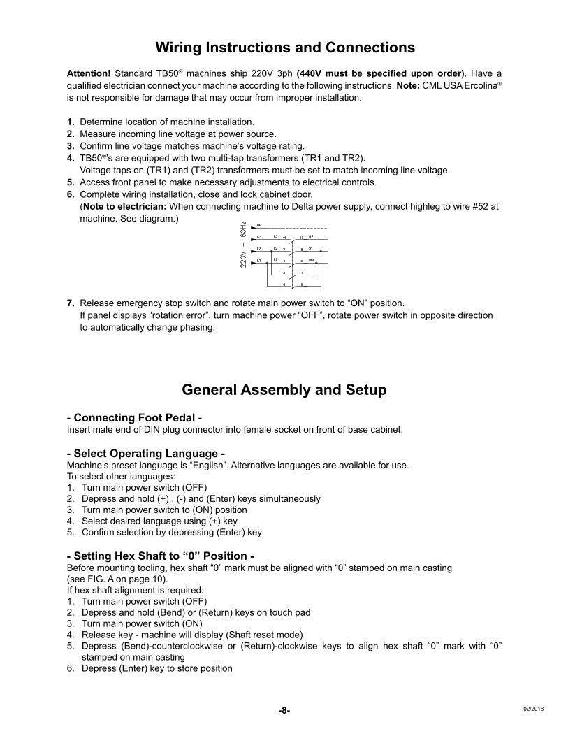
1. Determine location of machine installation.2. Measure incoming line voltage at power source.3. Confirm line voltage matches machine’s voltage rating.4. TB50®’s are equipped with two multi-tap transformers (TR1 and TR2). Voltage taps on (TR1) and (TR2) transformers must be set to match incoming line voltage.5. Access front panel to make necessary adjustments to electrical controls.6. Complete wiring installation, close and lock cabinet door. (Note to electrician: When connecting machine to Delta power supply, connect highleg to wire #52 at
machine. See diagram.)
7. Release emergency stop switch and rotate main power switch to “ON” position. If panel displays “rotation error”, turn machine power “OFF”, rotate power switch in opposite direction to automatically change phasing.
General Assembly and Setup
- Connecting Foot Pedal -Insert male end of DIN plug connector into female socket on front of base cabinet.
- Select Operating Language -Machine’s preset language is “English”. Alternative languages are available for use.To select other languages:1. Turn main power switch (OFF)2. Depress and hold (+) , (-) and (Enter) keys simultaneously3. Turn main power switch to (ON) position4. Select desired language using (+) key5. Confirm selection by depressing (Enter) key
- Setting Hex Shaft to “0” Position -Before mounting tooling, hex shaft “0” mark must be aligned with “0” stamped on main casting(see FIG. A on page 10).If hex shaft alignment is required:1. Turn main power switch (OFF)2. Depress and hold (Bend) or (Return) keys on touch pad3. Turn main power switch (ON)4. Release key - machine will display (Shaft reset mode)5. Depress (Bend)-counterclockwise or (Return)-clockwise keys to align hex shaft “0” mark with “0”
stamped on main casting6. Depress (Enter) key to store position
MOTOR BRAKE:
-9-02/2018
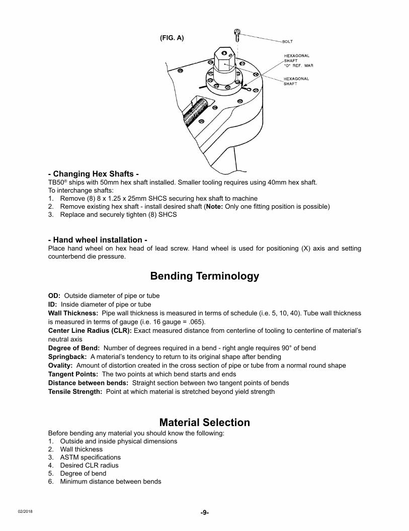
- Changing Hex Shafts -TB50® ships with 50mm hex shaft installed. Smaller tooling requires using 40mm hex shaft.To interchange shafts:1. Remove (8) 8 x 1.25 x 25mm SHCS securing hex shaft to machine2. Remove existing hex shaft - install desired shaft (Note: Only one fitting position is possible)3. Replace and securely tighten (8) SHCS
- Hand wheel installation -Place hand wheel on hex head of lead screw. Hand wheel is used for positioning (X) axis and setting counterbend die pressure.
Bending TerminologyOD: Outside diameter of pipe or tubeID: Inside diameter of pipe or tubeWall Thickness: Pipe wall thickness is measured in terms of schedule (i.e. 5, 10, 40). Tube wall thickness is measured in terms of gauge (i.e. 16 gauge = .065).Center Line Radius (CLR): Exact measured distance from centerline of tooling to centerline of material’s neutral axisDegree of Bend: Number of degrees required in a bend - right angle requires 90° of bendSpringback: A material’s tendency to return to its original shape after bendingOvality: Amount of distortion created in the cross section of pipe or tube from a normal round shapeTangent Points: The two points at which bend starts and endsDistance between bends: Straight section between two tangent points of bendsTensile Strength: Point at which material is stretched beyond yield strength
Material SelectionBefore bending any material you should know the following:1. Outside and inside physical dimensions2. Wall thickness3. ASTM specifications4. Desired CLR radius5. Degree of bend6. Minimum distance between bends
(FIG. A)

-10- 02/2018
- Proper Tooling Selection -
Refer to CML USA Ercolina® master catalog for recommended centerline bend radius for the material to be bent. If your application requires a CLR or profile that is not shown CML USA Ercolina® can quote special tooling on request. As a general guide when bending tubing and pipe, the heavier the wall thickness the tighter the centerline radius can be without distortion. Therefore when bending thin wall tube select the largest possible radius for best bend quality. Material requiring CLR smaller than two times the diameter should bent with a mandrel support, consult CML USA Ercolina® for more details. The standard counterbending dies are brass to accommodate a variety of material without conflict. Counterbending dies are also available in steel for heavy usage or polymer for applications in which the work piece finish is a factor. Note: When bending heavy wall material or solids a special roller style counterbending die is recommended.
- Installing counterbending die vise -Place vise assembly on tool post of counterbending die axis, vise assembly should pivot counterclockwise when mounted.
- Mounting center former -Ercolina® center formers are manufactured with an offset hex design ensuring proper installation. When mounted the center former’s gripper arm should face right side of machine.
- Mounting counterbending die -Ercolina® counterbending dies are designed for quick installation and removal. Insert male dovetail located on back of counterbend die into slot on counterbending die vise. Hold die firmly against vise, depress and rotate black knob clockwise securing die onto vise bracket. Installed properly, the “Ercolina®” logo will be facing the operator (see figure). Note: When bending heavy wall profiles and solids, standard counterbend die and vise must be removed and replaced with a roller counterbend die. Attention: Failure to use roller style die on heavy profiles may result in machine damage. (See Mounting “roller” counterbending die instructions.)
Note: Counterbending dies are wear items - Replace as necessary to ensure bend quality. Counterbending die should never contact center former when material is in former and tooling is in starting position.

-11-02/2018
- Counterbending die lubrication -For best results counterbending dies should be kept lubricated with Ercolina® spray grease - Part # 810. Proper lubrication extends counterbend die life and improves bend quality.
- Loading work piece - 1. Slide work piece into gripper arm and groove of center former2. Using hand wheel advance counterbending die forward until material rests securely between former
and die (see FIG. 1).3. Properly adjusted vise and counterbending die assembly should be perpendicular to work piece and
swing freely counterclockwise to release work piece (see FIG. 2). Note: If vise assembly pivots away from material at beginning of bend, reduce pressure on vise. Proper
counterbending die adjustment ensures satisfactory bends.
- Setting counterbending die axis to “0” at control panel -Depress (Enter) until display reads “0.000”. Note: Bender will not cycle if counterbending die axis is not at “0” position.
- Selecting proper bending speed -TB50® has a two-speed gearbox. As a general rule tubes ¼″ to 1⅜″ diameter can be bent at (speed 2), when bending larger diameter profiles (speed 1) should be used.
(FIG. 2)(FIG. 1)

-12- 02/2018
ERCOLINA® ROTARY DRAWTIE BAR ACCESSORY
Mega Bender® 030, TB60, TB050 Classic, 050KD, and SB48
Hex Drive Center Pivot Securing CenterformerPivot Shaft
Saddle Block Mounting Screw
Securing Saddle Block Installing Tie Bar Side Loading Tie Bar
Tie Bar Nuts Tie Bar Assembly Mounted Minimum Distance (fig. 1)
Tie Bar Assembly Speed Selector PW Reading
2½″2½″

-13-02/2018
● Never bend material exceeding machine specifications (i.e. high tensile, stainless, heavy profile or solid). Contact factory for machine capacity before bending.
● Always use lowest rpm setting. Reset tool shaft position – “C” axis 10° above “0” home – to avoid center former interference with machine case.
● Always use roller-style counterbending die.
● Mounting the roller-style counter bending die (Heavy Profiles or Solids). Heavy wall profiles and solid materials require a roller counterbending die. Remove the standard counterbend die vise assembly and slide roller onto vise mount-ing post. With material in former move roller die inward until material rests firmly between former and roller. Back roller die off approximately 2½″.
Warning: Never use roller die firmly against the material.
● Always use tie bar. Refer to mounting instructions. Tighten hex nuts neutral-ly, neither pushing nor pulling against tie bar assembly. Rotate hand wheel counter clockwise to remove play from counterbending vise screw.
● Always use lubrication on roller-style counterbending die and tool post.
● When bending – monitor machine display for PW or Amp reading. Never exceed 1200 PW/12 Amp.
Special Application Tooling – Part# 030TIEBAR
- Mounting “roller” counterbending die -When bending heavy wall profiles or solid materials a roller counterbending die must be used. Remove counterbend die vise assembly and place roller die onto machine tool post. With material in center former advance roller die inward until material rests firmly between former and roller. Retract roller die approximately 2½″ from material (refer to fig. 1 on page 13). Warning: Never use roller die flush against material – doing so will damage machine.

-14- 02/2018
Bender ProgrammingTB50® machines have (30) ten bending programs 0-9. Each program can store (9) nine individual bends.
- Control panel keys and their functions - (Return) Returns hex shaft to “0” position (Bend) Moves hex shaft to desired bend angle (Cursor) Used for editing program, bend angle and springback value (+) Increases values when editing (-) Decreases values when editing
- Important touch key functions - (Enter) and (-) (When in “0” position before bend cycle) Accesses “Data entry mode” (Enter) and (Bend) or (Return) Resets counterbending die axis to “0” (Enter), (+) and (-) (When turning main power on) Enters “Language selection mode” (Bend) or (Return) (When turning main power on) Enters “Shaft reset mode” (Cursor) (Any time during bending cycle) Enters “Program edit mode”
- Data entry mode -1. Depress (Cursor) key 2. Display reads “Data entry yes or no”3. Depress (+) = yes or (-) = no
- Selecting program number - Depress (+) until desired program is reached 0-9
- Erasing previous Information - Depress (-) hold for five seconds - process erases all previously stored information in program. Do not use process for simple editing. Display reads “Program No.1 12 .000” or similar
- Enter first bend angle - Depress (+) or (-) to enter desired bend angle. Note: While in programming mode,
(Bend) = 45◦, (Return) = 135◦ and (Cursor) = 90◦ keys help quickly move closer to desired angle
Depress (Enter) to store angle - Editing bend angles - Depress (+) to enter desired bend angle, (-) can be used should you go past desired angle Depress (Enter) to store angle
- Exiting data entry mode - Depress (Enter) Display reads “End of Date Entry”
- Returning to working display - Depress (Enter) Display Shows currently selected program and reads “Forward C counterbending die”
DATA ENTRY MODE+ = YES ENTER = NO
PROGRAM NO. 112 .000
END OF DATA ENTRY
Forward C.Bending D.mm 000.0 PO51 180°

-15-02/2018
- Initial springback setup -1. With previous steps completed -2. Initiate bend cycle by depressing (Bend) key or foot pedal switch3. Stop bend cycle when material begins to deflect (see FIG. 1)4. Observe degree reading on control panel. 5. Depress (Enter) to insert displayed springback value into program (Note: Springback value can be
edited later if needed). Springback must be set for each angle within program.
- Adjusting counterbending die support screw -Using Allen wrench, turn adjustment screw until contacting back side of vise. Secure screw with locking jam nut (see FIG. 2). Adjustment screw affects quality of bend and must be set for each material.
- Finishing bend -Depress and hold (Bend) key or foot pedal completing bend cycle (see FIG. 3)
- Return center former to “0” position -Depress and hold (Return) key or foot pedal until bender returns to “0” home position (see FIG. 4). Note: Display will automatically advance to next bend within program.
- Editing bend angles and springback values -Bend angles and springback values can be edited at any time during a bend cycle. Depress and release (Cursor) key - cursor will flash in the springback field. (+) and (-) keys can then be used to edit settings. Depress (Enter) key to store changes.
Pipe deflected from straight position
(FIG. 1)
(FIG. 4)
(FIG. 2)HOW TO USE THE ADJUSTMENT SCREW
ADJUSTMENTSCREW
ADJUSTMENTSCREW
(FIG. 3)

-16- 02/2018
Bending Troubleshooting Problem Probable Cause SolutionMaterial wrinkles or deforms Counterbend die pressure incorrect Increase counter die pressure
Radii too small for profile Increase CLR of tooling
Tube slips Poor quality tubing Confirm tubing measurements and replace with quality material
Counter bend die pressure is too low Increase die pressure tension
Material cracks or breaks Material quality poor Confirm material composition with mill certifications
Poor bend quality Material quality poor Replace material
CLR too small for profile Increase tooling CLR
Improper tooling adjustment Reset counterbend die pressure
Work piece ends are oval or Too much pressure on die Decrease die pressure, changedeformed adjustment screw setting (see fig. below)
Machine overloads Material exceeds machine’s capacity Reduce material size or wall thickness
Large material on high speed Use low speed (speed 1)
Counterbend die wears Excessive pressure on Decrease counterbend die pressureprematurely counterbend die
Lack of lubrication Use Ercolina® bending lubricant
Material dirty or rusted Replace material or clean surface
Tube has marks Poor tube quality Replace material
Tooling not ordered for material Consult factory
Improvement of bend qualityachieved by fine adjustmentof adjustment screw
Results achieved after bending without adjustment screw or by using it in a too backward position
Results achieved after bending without adjustment screw or by using it in a too forward position
Adjustment screw

-17-02/2018
Table of Display Errors Error Message Possible Cause Solution
High Tension High incoming voltage Reduce voltage
86 Missing phase Check plug connections and fuses
86 Faulty TV transformer Check incoming voltage/replace TV transformer
87 or 88 Missing phase Check plug and 1A1 connections
87 Faulty TA Check phase on 55 and 51 and then 55A and 50
87 or 88 “c” axis beyond 210 degrees Reset hex shaft
88 Emergency switch depressed Release emergency switch
88 Faulty “c” axis encoder Check control card connections, check encoder star wheel for damage and tightness. Clean with air if dirty
88 when pedal Faulty TR1 or rectifier Check outlets 40-42 for 100 volts ac is depressed Check outlets 46-45 for 110 volts dc
Over load light “ON” Machine in overload Switch off and on and refer to capacity chart
Over load light “ON” Faulty motor Check motor and connections
Warning light “ON” Emergency button is depressed Release the emergency switch
Warning light “ON” Motor safety switch is faulty Ensure switch is on, check incoming and outgoing power
Overload light “ON” Faulty “c” axis encoder Check encoder and connections
Display shows Faulty “c” axis encoder Replace incorrect rotation
- TB50® Accessories -A40/P - Two axis positioning table O50M - Mechanical tube and pipe positioner051 - Folding/Bending attachmentO50E - Counterbending die support bracket for radii 225mmO50I - ⅜″ - 2½″O50J - 2½″ - 3″810 - One 12-oz can of Ercolina® Spray Grease811 - 9pc case of Ercolina® Spray GreasePolymer counterbending die - quote on request
- Routine Maintenance -Keep machine clean and free of grease and debrisUsing supplied grease gun, lubricate gearbox at zirts every 40 hoursof use (see figure)Replace worn power cords or broken switchesClean encoder with electrical contact cleaner or canned air sprayAny repair or replacement of internal or external parts of machine must be made only by personnel trained/ authorized by Ercolina®
Replace worn toolingErcolina® reserves the right not to supply accessories or spare partsif machine has been modified

-18- 02/2018
Top Bender® Voltage Troubleshooting
Voltage Test Readings
Main switch: Outlets 52-50 Voltage = ____________ Power Supply Voltage
Outlets 52-50 Voltage = ____________ Power Supply Voltage
Main Transformer: Outlets 3-1 Voltage = ____________ Power Supply Voltage
Outlets 40-41 Voltage = ____________ +/- 100 VAC
Outlets 6-2 Voltage = ____________ 24 VAC
Outlets 45-46 Voltage = ____________ 110 DC (only in bend/return mode
___________________ motor circuit “OFF” position)
Board Transformer: Outlets 3-14 Voltage = ____________ Power Supply Voltage
Outlets 84-85 Voltage = ____________ 11 VAC
Motor Control Switch: Outlets 50-52 Voltage = ____________ Power Supply Voltage
Outlets 51-52 Voltage = ____________ Power Supply Voltage
Outlets 53-55A Voltage = ____________ Power Supply Voltage
Outlets 54-55A Voltage = ____________ Power Supply Voltage
Panel Control Switch: Outlets 50-51 Voltage = ____________ Power Supply Voltage
Outlets1-3 Voltage = ____________ Power Supply Voltage
Actual metered voltage at wall service= ___________
Voltage setting on main transformer = ____________
Voltage setting on board transformer = ___________

-19-02/2018
MOTOR BRAKE:
Electrical Schematic (220V)

-20- 02/2018
Electrical Schematic (220V) (cont.)

-21-02/2018
Commercial pipe and wall thickness Nominal Outside Schedule Schedule Schedule Schedule Schedule XX Size Dia. 5 10 40 80 160 Strong
⅛ .405 .049 .068 .095
¼ .540 .065 .088 .119
⅜ .675 .065 .091 .126
½ .840 .065 .083 .109 .147 .188 .294
¾ 1.050 .065 .083 .113 .154 .219 .308
1 1.315 .065 .109 .133 .179 .250 .358
1¼ 1.660 .065 .109 .140 .191 .250 .382
1½ 1.900 .065 .109 .145 .200 .281 .400
2 2.375 .065 .109 .154 .218 .344 .436
2½ 2.875 .083 .120 .203 .276 .375 .552
3 3.500 .083 .120 .216 .300 .438 .600
Bend ½ with ¾ with 1 with 1¼ with 1½ with 2 with Angle 1.8 CLR 2.2 CLR 2.6 CLR 3.5 CLR 3.9 CLR 5.9 CLR 5 .16 .19 .23 .31 .34 .52 10 .31 .38 .45 .61 .68 1.03 15 .47 .58 .68 .92 1.02 1.55 20 .63 .77 .91 1.22 1.36 2.07 25 .79 .96 1.13 1.53 1.70 2.58 30 .94 1.15 1.36 1.83 2.04 3.10 35 1.10 1.34 1.59 2.14 2.38 3.61 40 1.26 1.54 1.82 2.44 2.72 4.13 45 1.41 1.73 2.04 2.75 3.06 4.65 50 1.57 1.92 2.27 3.05 3.40 5.16 55 1.73 2.11 2.50 3.36 3.74 5.68 60 1.88 2.30 2.72 3.67 4.08 6.20 65 2.04 2.50 2.95 3.97 4.42 6.71 70 2.20 2.69 3.18 4.28 4.76 7.23 75 2.36 2.88 3.40 4.58 5.11 7.74 80 2.51 3.07 3.63 4.89 5.45 8.26 85 2.67 3.26 3.86 5.19 5.79 8.78 90 2.83 3.46 4.08 5.50 6.13 9.29 100 3.14 3.84 4.54 6.11 6.81 10.33 110 3.46 4.22 4.99 6.72 7.49 11.36 120 3.77 4.61 5.45 7.33 8.17 12.39 130 4.08 4.99 5.90 7.94 8.85 13.42 140 4.40 5.38 6.35 8.55 9.53 14.46 150 4.71 5.76 6.81 9.16 10.21 15.49 160 5.03 6.14 7.26 9.77 10.89 16.52 170 5.34 6.53 7.71 10.38 11.57 17.55 180 5.65 6.91 8.17 11.00 12.25 18.59
Material Length Required for Rotary Bends in Pipe“Guideline for material consumption”
To calculate total pipe length, add distance from end of pipe to the first bend, plus first bend arc length, plus distance to second bend
Tube Equivalent gauge in inches 10 .134 11 .120 12 .109 13 .095 14 .083 16 .065 18 .049 20 .035

-22- 02/2018
Mill
imet
ers
to In
ches
Con
vers
ion
M
M
Inch
es
MM
In
ches
M
M
Inch
es
MM
In
ches
Dec
imal
Dec
imal
Dec
imal
Dec
imal
1
0.03
9 29
1.
141
57
2.24
4 85
3.
347
2
0.07
9 30
1.
181
58
2.28
4 86
3.
386
3
0.11
8 31
1.
221
59
2.32
3 87
3.
425
4
0.15
8 32
1.
260
60
2.36
2 88
3.
465
5
0.19
7 33
1.
299
61
2.40
2 89
3.
504
6
0.23
6 34
1.
339
62
2.44
1 90
3.
543
7
0.27
6 35
1.
378
63
2.48
0 91
3.
583
8
0.31
5 36
1.
417
64
2.52
0 92
3.
622
9
0.35
4 37
1.
457
65
2.55
9 93
3.
661
10
0.
394
38
1.49
6 66
2.
598
94
3.70
1
11
0.
433
39
1.53
5 67
2.
638
95
3.74
0
12
0.
472
40
1.57
5 68
2.
677
96
3.78
0
13
0.
512
41
1.61
4 69
2.
717
97
3.81
9
14
0.
551
42
1.65
4 70
2.
756
98
3.85
8
15
0.
591
43
1.69
3 71
2.
795
99
3.89
8
16
0.
630
44
1.73
2 72
2.
835
100
3.93
7
17
0.
669
45
1.77
2 73
2.
874
110
4.33
1
18
0.
709
46
1.81
1 74
2.
913
120
4.72
4
19
0.
748
47
1.85
0 75
2.
953
130
5.11
8
20
0.
787
48
1.89
0 76
2.
992
140
5.51
2
21
0.
827
49
1.92
9 77
3.
032
150
5.90
6
22
0.
866
50
1.96
9 78
3.
071
160
6.29
9
23
0.
906
51
2.00
8 79
3.
110
170
6.69
3
24
0.
945
52
2.04
7 80
3.
150
180
7.08
7
25
0.
984
53
2.08
7 81
3.
189
190
7.48
0
26
1.
024
54
2.12
6 82
3.
228
200
7.87
4
27
1.
063
55
2.16
5 83
3.
268
250
9.84
3
28
1.
102
56
2.20
5 84
3.
307
300
11.8
11
Inch
es to
Mill
imet
ers
Con
vers
ion
Fr
actio
ns
Dec
imal
M
M
Frac
tions
D
ecim
al
MM
1 ⁄6
4 0.
016
0.39
7 33
⁄64
0.51
6 13
.096
1 ⁄3
2 0.
031
0.79
4 17
⁄32
0.53
1 13
.493
3 ⁄6
4 0.
047
1.19
1 35
⁄64
0.54
7 13
.890
1 ⁄1
6 0.
063
1.58
8 9 ⁄1
6 0.
563
14.2
87
5 ⁄ 64
0.07
8 1.
984
37⁄64
0.
578
14.6
84
3 ⁄32
0.09
4 2.
381
19⁄32
0.
594
15.0
81
7 ⁄64
0.10
9 2.
778
39⁄64
0.
609
15.4
78
⅛
0.12
5 3.
175
⅝
0.62
5 15
.874
9 ⁄6
4 0.
141
3.57
2 41
⁄64
0.64
1 16
.271
5 ⁄3
2 0.
156
3.96
9 21
⁄32
0.65
6 16
.668
11
⁄64
0.17
2 4.
366
43⁄64
0.
672
17.0
65
3 ⁄16
0.18
8 4.
763
11⁄16
0.
688
17.4
62
13⁄64
0.
203
5.15
9 45
⁄64
0.70
3 17
.859
7 ⁄3
2 0.
219
5.55
6 23
⁄32
0.71
9 18
.256
15
⁄64
0.23
4 5.
953
47⁄64
0.
734
18.6
53
¼
0.25
0 6.
350
¾
0.75
0 19
.049
17
⁄64
0.26
6 6.
744
49⁄64
0.
766
19.4
46
9 ⁄32
0.28
1 7.
144
25⁄32
0.
781
19.8
43
19⁄64
0.
297
7.54
1 51
⁄64
0.79
7 20
.240
5 ⁄1
6 0.
313
7.93
8 13
⁄16
0.81
3 20
.637
21
⁄64
0.32
8 8.
334
53⁄64
0.
828
21.0
34
11⁄32
0.
344
8.73
1 27
⁄32
0.84
4 21
.431
23
⁄64
0.36
0 9.
128
55⁄64
0.
859
21.8
28
⅜
0.37
5 9.
525
⅞
0.87
5 22
.224
25
⁄64
0.39
1 9.
922
57⁄64
0.
891
22.6
21
13⁄32
0.
406
10.3
19
29⁄32
0.
906
23.0
18
27⁄64
0.
422
10.7
16
59⁄64
0.
922
23.4
15
7 ⁄16
0.43
8 11
.113
15
⁄16
0.93
8 23
.812
29
⁄64
0.45
3 11
.509
61
⁄64
0.95
3 24
.209
15
⁄32
0.46
9 11
.906
31
⁄32
0.96
9 24
.606
31
⁄64
0.48
4 12
.303
63
⁄64
0.98
4 25
.003
½
0.
500
12.7
00
1 1.
000
25.3
99

-23-02/2018
Minimum Distance Between Bends By Center Line Radius
Radius of Minimum Distance Center Former Between Bends Inches Metric Inches Metric .394 10 NA NA .472 12 NA NA .591 15 NA NA .630 16 NA NA .709 18 NA NA .787 20 NA NA .945 24 NA NA 1.023 26 NA NA 1.102 28 NA NA 1.181 30 NA NA 1.259 32 NA NA 1.417 36 2.362 60 1.811 46 3.149 80 2.204 56 3.740 95 2.637 67 3.937 100 3.228 82 3.937 100 3.543 90 4.330 110 3.937 100 4.330 110 4.133 105 4.330 110 4.409 112 4.330 110 4.724 120 5.511 140 5.118 130 5.511 140 5.708 145 5.905 150 6.692 170 5.905 150 7.283 185 5.905 150 7.480 190 5.905 150 8.858 225 5.905 150 10.236 260 6.299 160 11.811 300 6.299 160
TB50® with pipe kit TB50® with tube kit Min. Min. Size CLR Former part # Counterbend # Size CLR Former part # Counterbend # Wall Wall
½″ 1.8 .109 153R046P0500 155P0500 ¾″ 2.6 .039 153R067T0750 154T0750
¾″ 2.2 .113 153R056P0750 155P0750 ⅞″ 2.6 .039 153R067T0875 154T0875
1″ 2.6 .133 153R067P1000 155P1000 1″ 3.2 .039 153R082T1000 154T1000
1¼″ 3.5 .140 153R090P1250 155P1250 1¼″ 4.4 .039 153R112T1250 154T1250
1½″ 3.9 .145 153R100P1500 155P1500 1½″ 5.9 .047 153R150T1500 154T1500
2″ 5.9 .154 153R150P2000 155P2000 1¾″ 6.7 .059 153R170T1750 154T1750
2″ 7.5 .059 153R190T2000 154T2000
Pipe kit only # PIPEKIT1 Tube kit only # TUBEKIT1

Bewa
re of
Imita
tions N
ote:
*220
V 1
pha
se m
odel
ava
ilabl
e. C
onsu
lt C
ML
US
A In
c. E
rcol
ina
with
app
licat
ion
ques
tions
• A
ll ca
paci
ties
base
d on
mild
gra
de m
ater
ials
; hea
vy w
all a
nd h
igh
tens
ile m
ater
ials
redu
ce
mac
hine
cap
acity
• M
achi
nes
orde
red
volta
ge s
peci
fic •
Con
sult
fact
ory
for p
rodu
ctio
n ap
plic
atio
ns a
nd m
achi
ne d
uty
cycl
es .
“ 40 Y
ears
Exce
llenc
e in Q
ualit
y, Su
ppor
t and
Serv
ice ”
“ 40 Y
ears
Exce
llenc
e in Q
ualit
y, Su
ppor
t and
Serv
ice ”
Non
-man
drel
Rot
ary
Dra
w B
ende
rs• R
otar
y dr
aw b
ende
rs to
5″ p
ipe
capa
city
• Man
ual 3
Axi
s C
ontro
l •
Mat
eria
l spr
ingb
ack
com
pens
atio
n• U
ser f
riend
ly p
rogr
amm
able
con
trols
• A
ll m
achi
nes
and
tool
ing
in “S
tock
”• S
ampl
e be
nds
upon
requ
est
Mode
l TB
180
TB13
0 TB
100
030 M
ega B
ende
r TB
60
050P
LUS
SB48
SB
48PL
US
MB42
B Me
di Be
nder
070
Tub
e Ca
pacit
y 6″
- .1
20 w
all
5″
4″
3″
2½″
2½″
2″
2″
1½″
1¼″ –
.065
wal
l P
ipe
Capa
city
6″ S
ch. 1
0 4″
Sch
. 40
3″ S
ch. 4
0 2½
″ Sch
. 10
2″ S
ch. 4
0 2″
Sch
. 40
1½″ S
ch. 4
0 1½
″ Sch
. 40
1″ S
ch. 4
0 1″
Sch
. 10
Squ
are
Tube
Cap
acity
4″
4″
3½
″ 2″
2″
2″
1½
″ 1½
″ 1¼
″ ¾
″ M
axim
um “C
LR”
39¼
″ 27
½″
17″
15″
15″
11⅞
″ 8⅞
″ 8⅞
″ 7½
″ 6⅞
″ D
egre
e of
Ben
d 0-
210°
0-
210°
0-
210°
0-
210°
0-
210°
0-
210°
0-
210°
0-
210°
0-
210°
0-
210º
Ben
ding
Spe
ed “R
PM”
Varia
ble
to 1
Va
riabl
e to
.75
Varia
ble
to 1
.3
Varia
ble
.6 to
2.2
1.
7 or
3.4
1.
2 2
2 2
2.2
NC
Prog
ram
min
g To
uch
Scre
en
Touc
h Sc
reen
To
uch
Scre
en
Touc
hpad
To
uchp
ad
Touc
hpad
To
uchp
ad
Touc
hpad
To
uchp
ad
LED
Num
ber o
f Pro
gram
s Un
limite
d wi
th U
SB
Unlim
ited
with
USB
Un
limite
d wi
th U
SB
30
30
1 30
1
30
1 V
olta
ge
440V
/3ph
22
0V o
r 440
V/3p
h 22
0V o
r 440
V/3p
h *2
20V
or 4
40V/
3ph
22
0V o
r 440
V/3p
h 22
0V 1
ph
120V
or 2
20V/
3ph
120V
1ph
12
0V
120V
Mand
rel U
pgra
de
Avai
labl
e
TB18
0
030 M
ega B
ende
rTB
130
SB48
SB48
PLUS
050P
LUS
MB42
BMe
di Be
nder
070
Man
drel
Mod
els
Avai
labl
e
TM76
View
Erc
olin
a® D
emo
Vide
os O
nlin
e:w
ww
.erc
olin
a-us
a.co
mht
tps:
//ww
w.y
outu
be.c
om/u
ser/
Erco
linaU
SA#g
/u
TB60
TB10
0
Tube
, Pip
e and
Prof
ile Be
nder
s
CM
L U
SA In
c. E
rcol
ina®
3100
Res
earc
h P
arkw
ay
Dav
enpo
rt, IA
528
06P
hone
563
-391
-770
0 o
r Fa
x 56
3-39
1-77
10w
ww
.erc
olin
a-us
a.co
m •
inf
o@er
colin
a-us
a.co
m
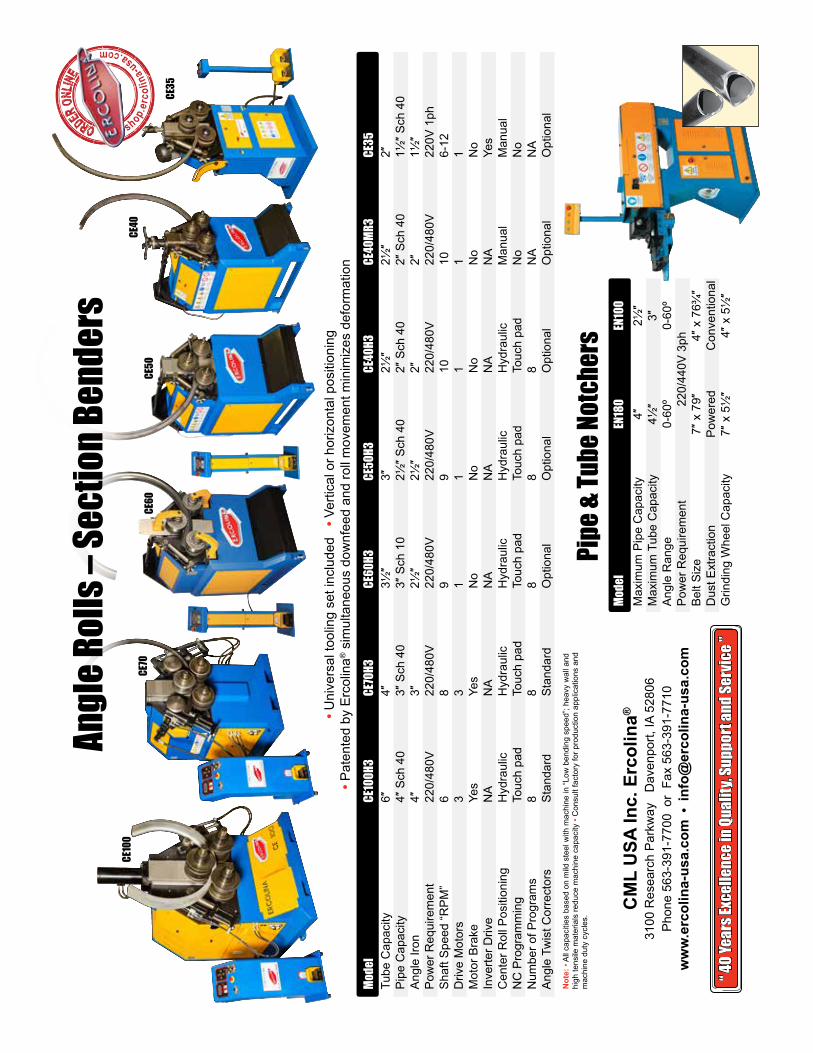
Mod
el
CE10
0H3
CE70
H3
CE60
H3
CE50
H3
CE40
H3
CE40
MR3
CE35
T
ube
Cap
acity
6″
4″
3½
″ 3″
2½
″ 2½
″ 2″
Pip
e C
apac
ity
4″ S
ch 4
0
3″ S
ch 4
0 3″
Sch
10
2½
″ Sch
40
2″ S
ch 4
0 2″
Sch
40
1½″ S
ch 4
0 A
ngle
Iron
4″
3″
2½
″ 2½
″ 2″
2″
1½
″ P
ower
Req
uire
men
t 22
0/48
0V
220/
480V
22
0/48
0V
220/
480V
22
0/48
0V
220/
480V
22
0V 1
ph S
haft
Spe
ed “R
PM
” 6
8 9
9 10
10
6-
12 D
rive
Mot
ors
3 3
1 1
1 1
1 M
otor
Bra
ke
Yes
Yes
No
No
No
No
No
Inv
erte
r Driv
e N
A N
A N
A N
A N
A N
A Ye
s C
ente
r Rol
l Pos
ition
ing
Hyd
raul
ic
Hyd
raul
ic
Hyd
raul
ic
Hyd
raul
ic
Hyd
raul
ic
Man
ual
Man
ual
NC
Pro
gram
min
g To
uch
pad
Touc
h pa
d To
uch
pad
Touc
h pa
d To
uch
pad
No
No
Num
ber o
f Pro
gram
s 8
8 8
8 8
NA
NA
Ang
le T
wis
t Cor
rect
ors
Sta
ndar
d S
tand
ard
Opt
iona
l O
ptio
nal
Opt
iona
l O
ptio
nal
Opt
iona
l
Pipe
& Tu
be No
tche
rs M
odel
EN
180
EN10
0 M
axim
um P
ipe
Cap
acity
4″
2½
″ M
axim
um T
ube
Cap
acity
4½
″ 3″
Ang
le R
ange
0-
60º
0-60
º P
ower
Req
uire
men
t
2
20/4
40V
3ph
B
elt S
ize
7″ x
79″
4″
x 7
6¾″
Dus
t Ext
ract
ion
Pow
ered
C
onve
ntio
nal
Grin
ding
Whe
el C
apac
ity
7″ x
5½
″ 4″
x 5
½″
Not
e: •
All
capa
citie
s ba
sed
on m
ild s
teel
with
mac
hine
in “L
ow b
endi
ng s
peed
”; he
avy
wal
l and
hi
gh te
nsile
mat
eria
ls re
duce
mac
hine
cap
acity
• C
onsu
lt fa
ctor
y fo
r pro
duct
ion
appl
icat
ions
and
m
achi
ne d
uty
cycl
es.
“ 40 Y
ears
Exce
llenc
e in Q
ualit
y, Su
ppor
t and
Serv
ice ”
“ 40 Y
ears
Exce
llenc
e in Q
ualit
y, Su
ppor
t and
Serv
ice ”
• Uni
vers
al to
olin
g se
t inc
lude
d •
Ver
tical
or h
oriz
onta
l pos
ition
ing
• Pat
ente
d by
Erc
olin
a® s
imul
tane
ous
dow
nfee
d an
d ro
ll m
ovem
ent m
inim
izes
def
orm
atio
n
shop.e
rcol
ina-u
sa.com
ORDER ON
LINE
CE10
0CE
70CE
60
CE35
CE40
CE50
Angl
e Rol
ls – S
ectio
n Ben
ders

CML USA Inc. Ercolina®
3100 Research Parkway Davenport, IA 52806Phone 563-391-7700 or Fax 563-391-7710
www.ercolina-usa.com ● [email protected] the new CNC Site: www.ercolinacnc.com
Beware of Imitations