Embed Size (px)
Citation preview
© Copyright 2015, Holo/Or Ltd. — Kiryat Weizmann P.O.B 1051, Rehovot, 76114, Israel Phone: +972 (8)-9409687/8, Fax: +972 (8)-9409606
Holo/Or Ltd. Confidential information
Top-Hat beam shaper
Installation manual
Date: 26/5/2015
Version: 1

© Copyright 2015, Holo/Or Ltd. — Kiryat Weizmann P.O.B 1051, Rehovot, 76114, Israel Phone: +972 (8)-9409687/8, Fax: +972 (8)-9409606
Holo/Or Ltd. Confidential information
Contents
1. Safety .................................................................................................................................................... 3
2. Handling:............................................................................................................................................... 4
3. Introduction ........................................................................................................................................... 5
4. Initial optical setup ................................................................................................................................ 7
5. Installing the TH beam shaper .............................................................................................................. 9
6. Problems and solutions: ...................................................................................................................... 11
7. General tips: ........................................................................................................................................ 18
© Copyright 2015, Holo/Or Ltd. — Kiryat Weizmann P.O.B 1051, Rehovot, 76114, Israel Phone: +972 (8)-9409687/8, Fax: +972 (8)-9409606
Holo/Or Ltd. Confidential information
1. Safety
General recommendations when working with a laser
http://web.princeton.edu/sites/ehs/laserguide/appendixB.htm
Locate beam at waist level or below. Do not place beam at eye level.
Close and cover your eyes when stooping down around the beam (where you
will pass the beam at eye level).
When leaning over a table, beware of beam directed upward.
Enclose as much of the beam as possible.
Do not direct beam toward doors or windows.
Terminate beams or reflections with fire-resistant beam stops. Anodized
aluminum or aluminum painted black (which is not necessarily fire-resistant)
can work well for this purpose.
Use surfaces that minimize specular reflections (mirror-like reflection).
Locate controls so that the operator is not exposed to beam hazards.
Make sure warning/indicator lights can be seen through protective filters.
If you can see the beam through your laser eyewear, you are not fully
protected.
View applications remotely.
Do not wear watches or reflective jewelry around Class 3B or 4 lasers.
Do not wear neckties around Class 4 open beam lasers.
In reality, all interlocks can fail.
The best defense is good understanding of the hazards.
Recommendations for alignment:
Isolate process.
Use lowest practical power.
View diffuse reflections only.
Use IR/UV viewing cards/eyewear.
Where possible, use HeNe alignment lasers.
© Copyright 2015, Holo/Or Ltd. — Kiryat Weizmann P.O.B 1051, Rehovot, 76114, Israel Phone: +972 (8)-9409687/8, Fax: +972 (8)-9409606
Holo/Or Ltd. Confidential information
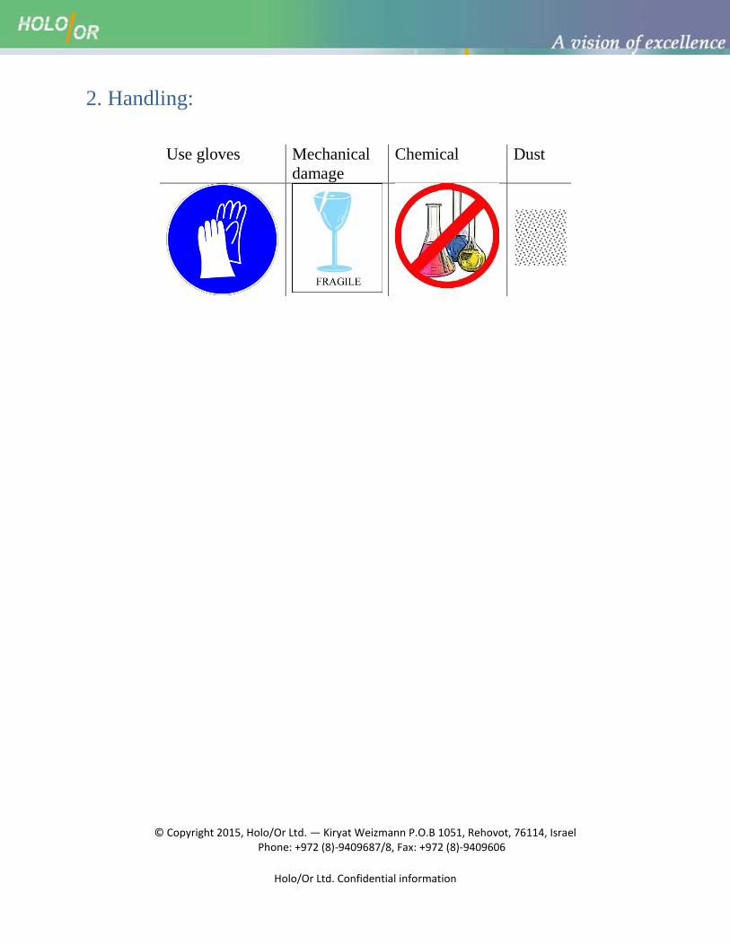
2. Handling:
Use gloves Mechanical
damage
Chemical Dust
© Copyright 2015, Holo/Or Ltd. — Kiryat Weizmann P.O.B 1051, Rehovot, 76114, Israel Phone: +972 (8)-9409687/8, Fax: +972 (8)-9409606
Holo/Or Ltd. Confidential information
3. Introduction
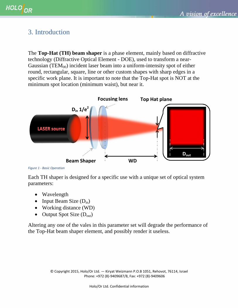
The Top-Hat (TH) beam shaper is a phase element, mainly based on diffractive
technology (Diffractive Optical Element - DOE), used to transform a near-
Gaussian (TEM00) incident laser beam into a uniform-intensity spot of either
round, rectangular, square, line or other custom shapes with sharp edges in a
specific work plane. It is important to note that the Top-Hat spot is NOT at the
minimum spot location (minimum waist), but near it.
Figure 1 - Basic Operation
Each TH shaper is designed for a specific use with a unique set of optical system
parameters:
Wavelength
Input Beam Size (Din)
Working distance (WD)
Output Spot Size (Dout)
Altering any one of the vales in this parameter set will degrade the performance of
the Top-Hat beam shaper element, and possibly render it useless.
WD
Focusing lens
Beam Shaper
Din 1/e2
Dout
Top Hat plane
© Copyright 2015, Holo/Or Ltd. — Kiryat Weizmann P.O.B 1051, Rehovot, 76114, Israel Phone: +972 (8)-9409687/8, Fax: +972 (8)-9409606
Holo/Or Ltd. Confidential information
The beam shaper can be a:
a. Focal Beam Shaper: Hybrid element (singlet lens) or a module, which gives
a Top-Hat intensity distribution at a specific working distance (EFL of the
lens or distance from exit location of the module to Top-Hat plane).
b. Angular Beam Shaper: Optical element (window) which gives a Top-Hat
intensity distribution at infinity or in the focal plane of an aberration free
customer's lens.
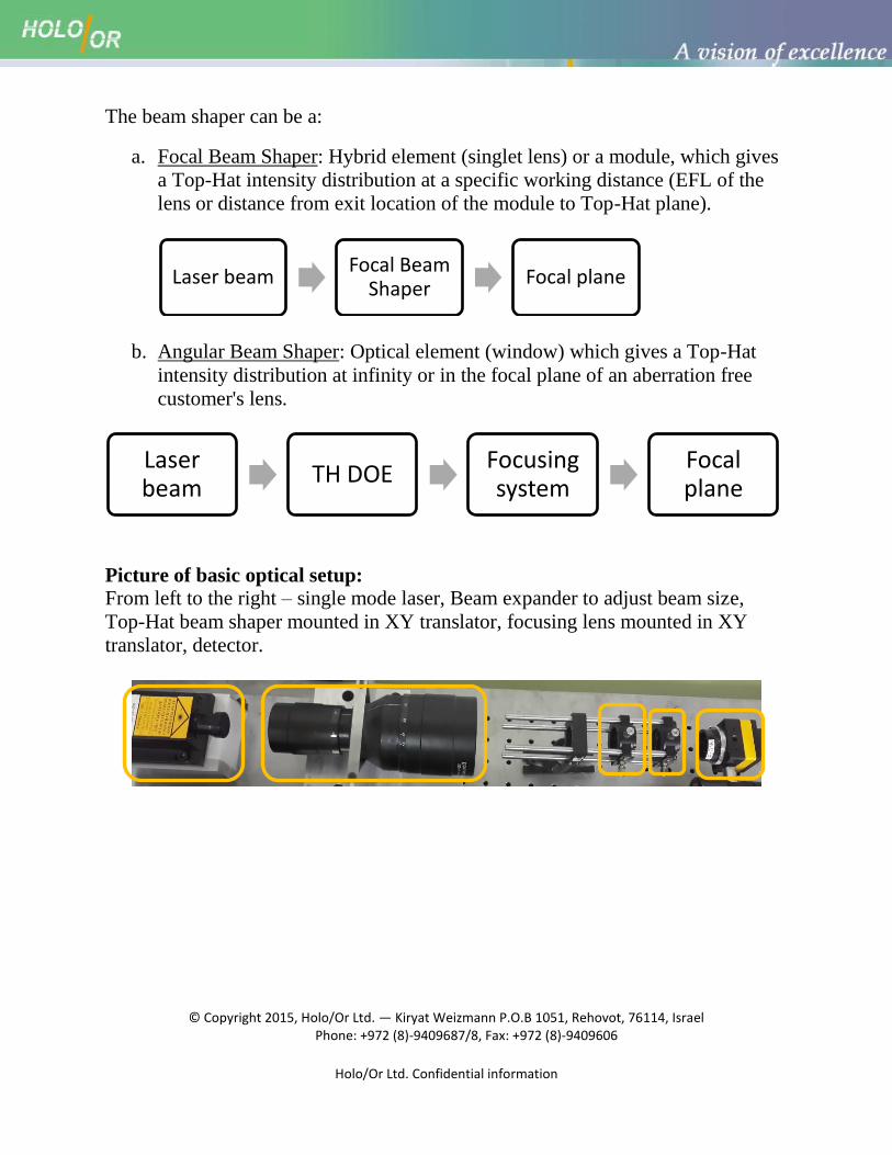
Picture of basic optical setup:
From left to the right – single mode laser, Beam expander to adjust beam size,
Top-Hat beam shaper mounted in XY translator, focusing lens mounted in XY
translator, detector.
Laser beam Focal Beam
Shaper Focal plane
Laser beam
TH DOE Focusing system
Focal plane
© Copyright 2015, Holo/Or Ltd. — Kiryat Weizmann P.O.B 1051, Rehovot, 76114, Israel Phone: +972 (8)-9409687/8, Fax: +972 (8)-9409606
Holo/Or Ltd. Confidential information
4. Initial optical setup
The TH beam shaper is mainly being used in situations where highly uniform
image and superb accuracy on output shape and size are important. This comes
with a cost:
a) Sensitive to X-Y displacement
b) Sensitive to input beam diameter
c) Sensitive to working distance
d) Requires M2 < 1.3 (higher value will result in poorer results)
e) Some designs are rotation sensitive (mainly, non-radial designs)
To solve the issues above, some solutions on the system level can be applied:
f) X-Y stages
g) Beam expander (preferred variable)
h) Z-stage for Focusing module or stage for focal plane (@WD)
i) Spatial filter
j) Optional notches for correct placement
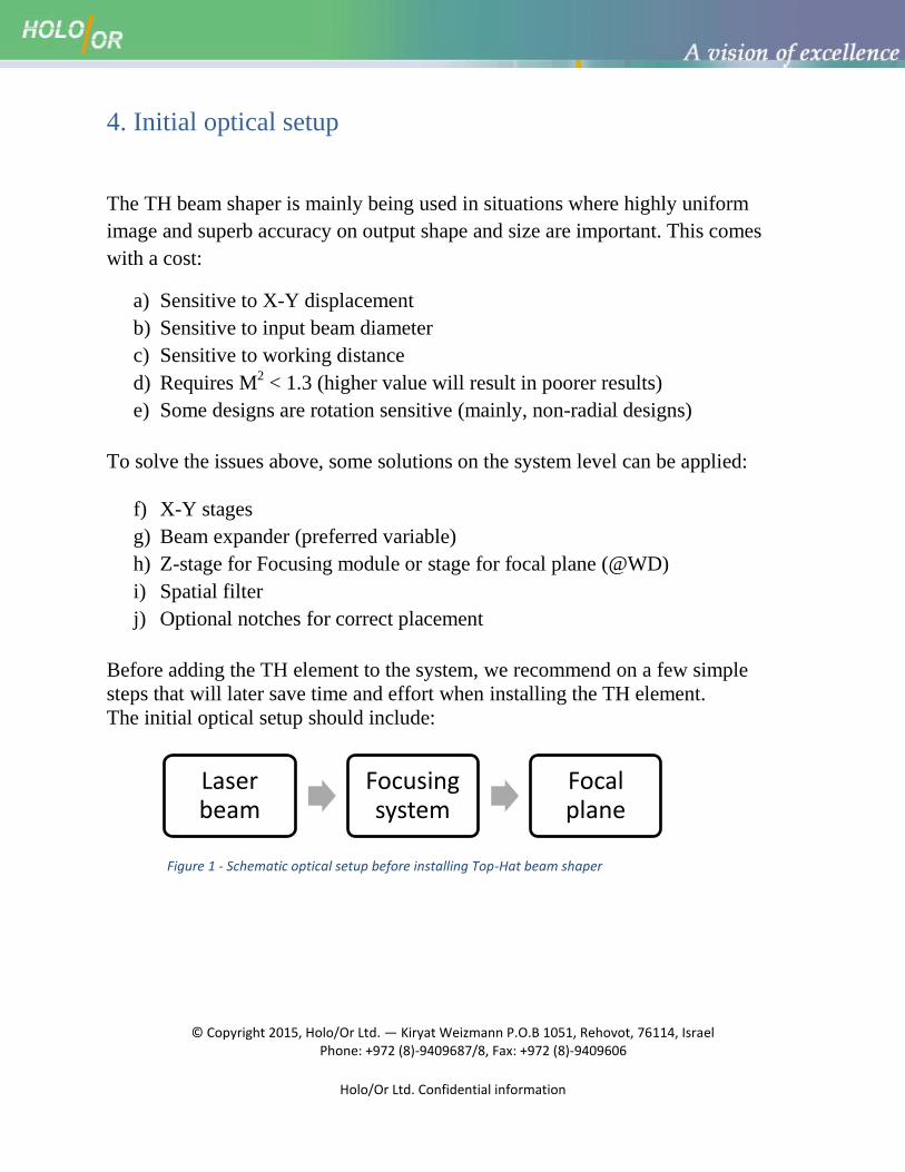
Before adding the TH element to the system, we recommend on a few simple
steps that will later save time and effort when installing the TH element.
The initial optical setup should include:
Figure 1 - Schematic optical setup before installing Top-Hat beam shaper
Laser beam
Focusing system
Focal plane
© Copyright 2015, Holo/Or Ltd. — Kiryat Weizmann P.O.B 1051, Rehovot, 76114, Israel Phone: +972 (8)-9409687/8, Fax: +972 (8)-9409606
Holo/Or Ltd. Confidential information
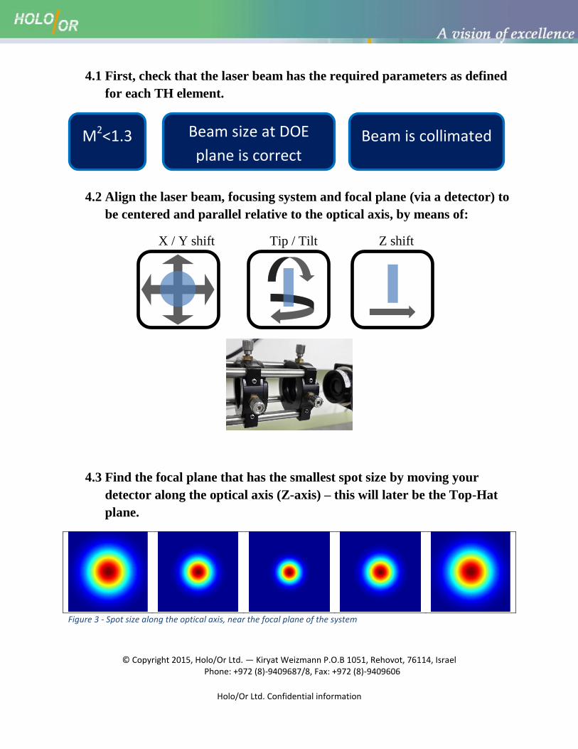
4.1 First, check that the laser beam has the required parameters as defined
for each TH element.
4.2 Align the laser beam, focusing system and focal plane (via a detector) to
be centered and parallel relative to the optical axis, by means of:
X / Y shift Tip / Tilt Z shift
4.3 Find the focal plane that has the smallest spot size by moving your
detector along the optical axis (Z-axis) – this will later be the Top-Hat
plane.
Figure 3 - Spot size along the optical axis, near the focal plane of the system
Beam is collimated Beam size at DOE
plane is correct
M2<1.3
© Copyright 2015, Holo/Or Ltd. — Kiryat Weizmann P.O.B 1051, Rehovot, 76114, Israel Phone: +972 (8)-9409687/8, Fax: +972 (8)-9409606
Holo/Or Ltd. Confidential information
5. Installing the TH beam shaper
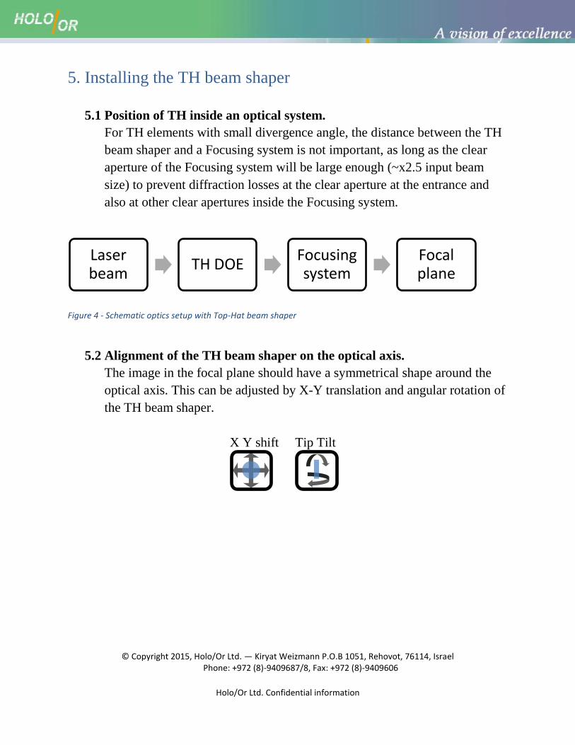
5.1 Position of TH inside an optical system.
For TH elements with small divergence angle, the distance between the TH
beam shaper and a Focusing system is not important, as long as the clear
aperture of the Focusing system will be large enough (~x2.5 input beam
size) to prevent diffraction losses at the clear aperture at the entrance and
also at other clear apertures inside the Focusing system.
Figure 4 - Schematic optics setup with Top-Hat beam shaper
5.2 Alignment of the TH beam shaper on the optical axis.
The image in the focal plane should have a symmetrical shape around the
optical axis. This can be adjusted by X-Y translation and angular rotation of
the TH beam shaper.
X Y shift Tip Tilt
Laser beam
TH DOE Focusing system
Focal plane
© Copyright 2015, Holo/Or Ltd. — Kiryat Weizmann P.O.B 1051, Rehovot, 76114, Israel Phone: +972 (8)-9409687/8, Fax: +972 (8)-9409606
Holo/Or Ltd. Confidential information
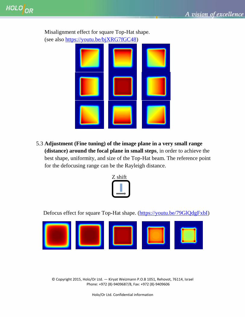
Misalignment effect for square Top-Hat shape.
(see also https://youtu.be/bjXRG7fGC48)
5.3 Adjustment (Fine tuning) of the image plane in a very small range
(distance) around the focal plane in small steps, in order to achieve the
best shape, uniformity, and size of the Top-Hat beam. The reference point
for the defocusing range can be the Rayleigh distance.
Z shift
Defocus effect for square Top-Hat shape. (https://youtu.be/79GlQdgFxbI)
© Copyright 2015, Holo/Or Ltd. — Kiryat Weizmann P.O.B 1051, Rehovot, 76114, Israel Phone: +972 (8)-9409687/8, Fax: +972 (8)-9409606
Holo/Or Ltd. Confidential information
6. Problems and solutions:
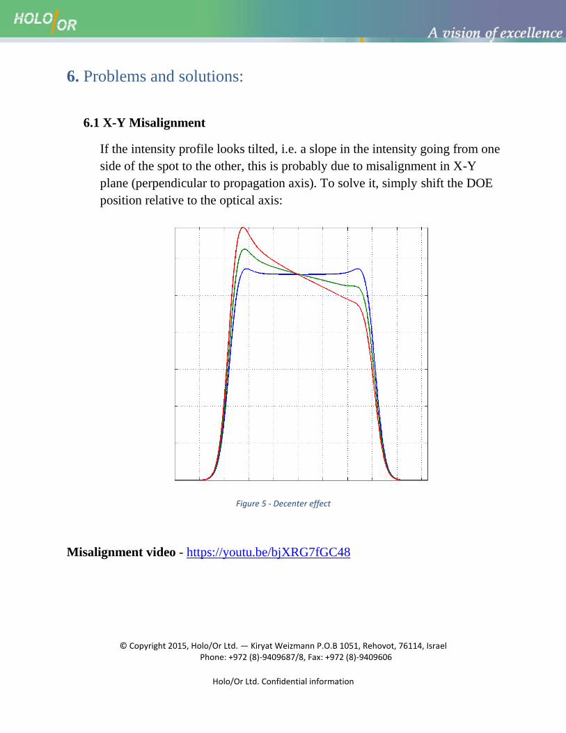
6.1 X-Y Misalignment
If the intensity profile looks tilted, i.e. a slope in the intensity going from one
side of the spot to the other, this is probably due to misalignment in X-Y
plane (perpendicular to propagation axis). To solve it, simply shift the DOE
position relative to the optical axis:
Figure 5 - Decenter effect
Misalignment video - https://youtu.be/bjXRG7fGC48
© Copyright 2015, Holo/Or Ltd. — Kiryat Weizmann P.O.B 1051, Rehovot, 76114, Israel Phone: +972 (8)-9409687/8, Fax: +972 (8)-9409606
Holo/Or Ltd. Confidential information
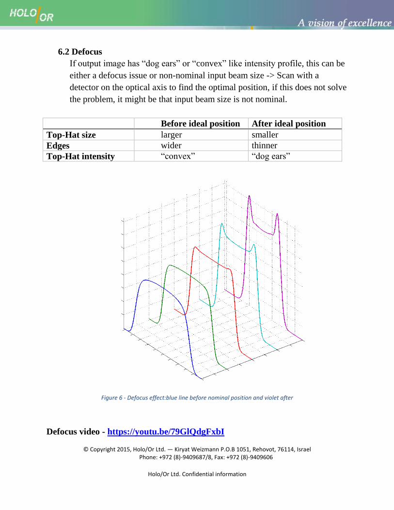
6.2 Defocus
If output image has “dog ears” or “convex” like intensity profile, this can be
either a defocus issue or non-nominal input beam size -> Scan with a
detector on the optical axis to find the optimal position, if this does not solve
the problem, it might be that input beam size is not nominal.
Before ideal position After ideal position
Top-Hat size larger smaller
Edges wider thinner
Top-Hat intensity “convex” “dog ears”
Figure 6 - Defocus effect:blue line before nominal position and violet after
Defocus video - https://youtu.be/79GlQdgFxbI
© Copyright 2015, Holo/Or Ltd. — Kiryat Weizmann P.O.B 1051, Rehovot, 76114, Israel Phone: +972 (8)-9409687/8, Fax: +972 (8)-9409606
Holo/Or Ltd. Confidential information
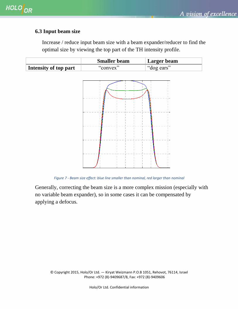
6.3 Input beam size
Increase / reduce input beam size with a beam expander/reducer to find the
optimal size by viewing the top part of the TH intensity profile.
Smaller beam Larger beam
Intensity of top part “convex” “dog ears”
Figure 7 - Beam size effect: blue line smaller than nominal, red larger than nominal
Generally, correcting the beam size is a more complex mission (especially with
no variable beam expander), so in some cases it can be compensated by
applying a defocus.
© Copyright 2015, Holo/Or Ltd. — Kiryat Weizmann P.O.B 1051, Rehovot, 76114, Israel Phone: +972 (8)-9409687/8, Fax: +972 (8)-9409606
Holo/Or Ltd. Confidential information
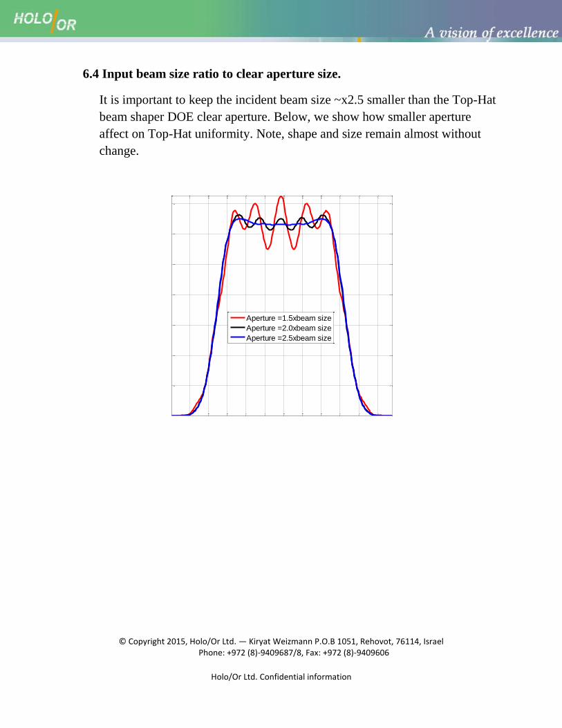
6.4 Input beam size ratio to clear aperture size.
It is important to keep the incident beam size ~x2.5 smaller than the Top-Hat
beam shaper DOE clear aperture. Below, we show how smaller aperture
affect on Top-Hat uniformity. Note, shape and size remain almost without
change.
Aperture =1.5xbeam size
Aperture =2.0xbeam size
Aperture =2.5xbeam size
© Copyright 2015, Holo/Or Ltd. — Kiryat Weizmann P.O.B 1051, Rehovot, 76114, Israel Phone: +972 (8)-9409687/8, Fax: +972 (8)-9409606
Holo/Or Ltd. Confidential information
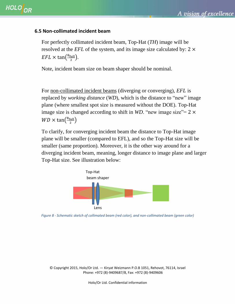
6.5 Non-collimated incident beam
For perfectly collimated incident beam, Top-Hat (TH) image will be
resolved at the EFL of the system, and its image size calculated by:
.
Note, incident beam size on beam shaper should be nominal.
For non-collimated incident beams (diverging or converging), EFL is
replaced by working distance (WD), which is the distance to “new” image
plane (where smallest spot size is measured without the DOE). Top-Hat
image size is changed according to shift in WD. “new image size”=
To clarify, for converging incident beam the distance to Top-Hat image
plane will be smaller (compared to EFL), and so the Top-Hat size will be
smaller (same proportion). Moreover, it is the other way around for a
diverging incident beam, meaning, longer distance to image plane and larger
Top-Hat size. See illustration below:
Figure 8 - Schematic sketch of collimated beam (red color), and non-collimated beam (green color)
Top-Hat
beam shaper
Lens
© Copyright 2015, Holo/Or Ltd. — Kiryat Weizmann P.O.B 1051, Rehovot, 76114, Israel Phone: +972 (8)-9409687/8, Fax: +972 (8)-9409606
Holo/Or Ltd. Confidential information
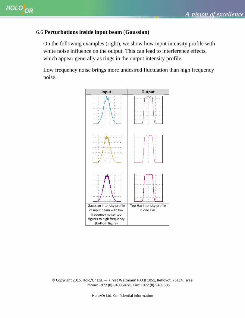
6.6 Perturbations inside input beam (Gaussian)
On the following examples (right), we show how input intensity profile with
white noise influence on the output. This can lead to interference effects,
which appear generally as rings in the output intensity profile.
Low frequency noise brings more undesired fluctuation than high frequency
noise.
Input Output
Gaussian intensity profile of input beam with low
frequency noise (top figure) to high frequency
(bottom figure)
Top-Hat intensity profile in one axis.
© Copyright 2015, Holo/Or Ltd. — Kiryat Weizmann P.O.B 1051, Rehovot, 76114, Israel Phone: +972 (8)-9409687/8, Fax: +972 (8)-9409606
Holo/Or Ltd. Confidential information
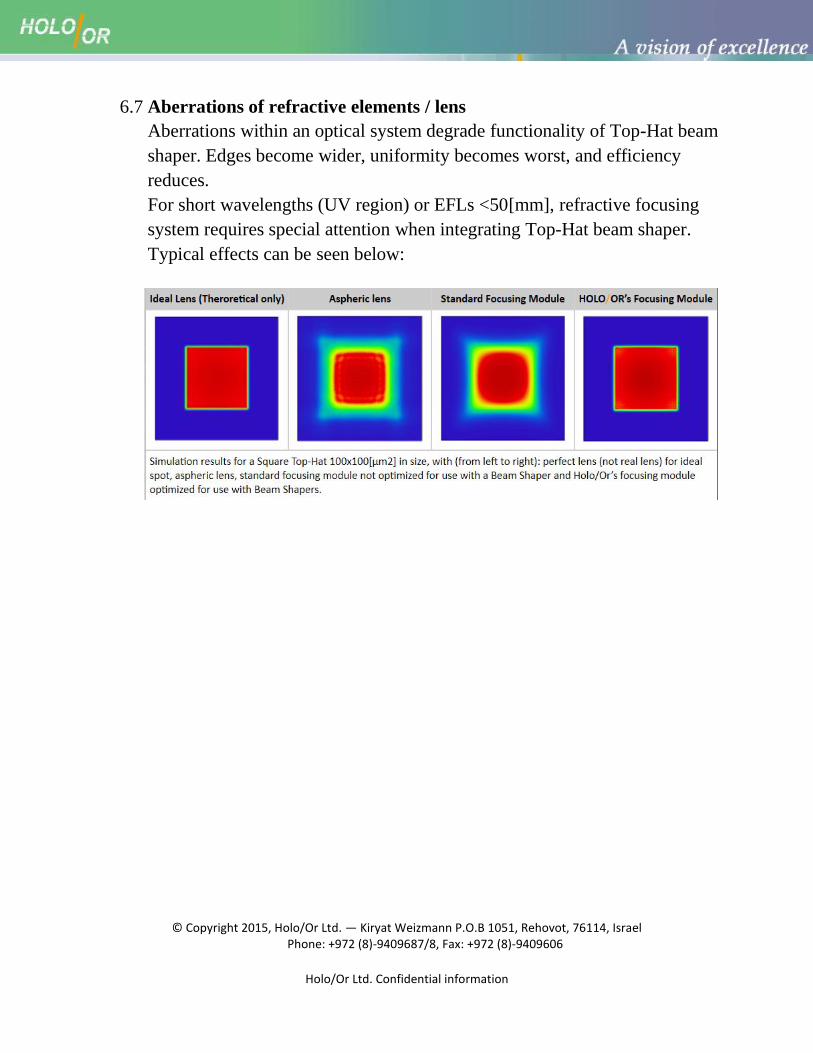
6.7 Aberrations of refractive elements / lens
Aberrations within an optical system degrade functionality of Top-Hat beam
shaper. Edges become wider, uniformity becomes worst, and efficiency
reduces.
For short wavelengths (UV region) or EFLs <50[mm], refractive focusing
system requires special attention when integrating Top-Hat beam shaper.
Typical effects can be seen below:
© Copyright 2015, Holo/Or Ltd. — Kiryat Weizmann P.O.B 1051, Rehovot, 76114, Israel Phone: +972 (8)-9409687/8, Fax: +972 (8)-9409606
Holo/Or Ltd. Confidential information
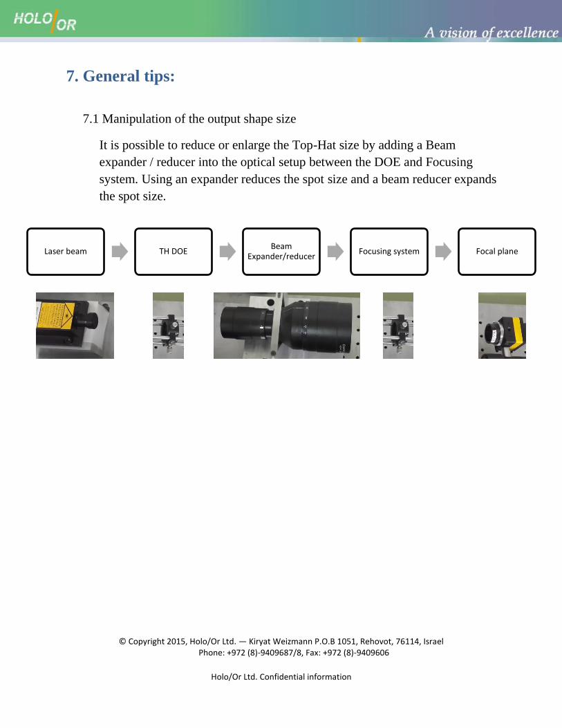
7. General tips:
7.1 Manipulation of the output shape size
It is possible to reduce or enlarge the Top-Hat size by adding a Beam
expander / reducer into the optical setup between the DOE and Focusing
system. Using an expander reduces the spot size and a beam reducer expands
the spot size.
Laser beam TH DOE Beam
Expander/reducer Focusing system Focal plane