Embed Size (px)
Citation preview

USER MANUAL
Deep Bed FilterTop Mount Series with Manual Valve
NOTE: Stop the pump before changing the valve position!
Please read and follow this MANUAL before install
and use the filter!

1. Deep Bed Filter Parameters
Model A (mm) B (mm) D (mm)Valve
ConnectionsSand Carbon
Cation
Resin
Volume
(Liter)Top Opening
Flow Rate
(m3/h)
HT-DB12 1225 1005 300 1" / 32mm 92 30 50 83 2.5" thread 1.6~2.2
HT-DB13 1390 1350 325 1" / 32mm 110 37 63 99 2.5" thread 2.0~2.5
HT-DB14 1650 1625 350 1" / 32mm 150 50 90 113 2.5" thread 2.5~3.0
HT-DB16 1650 1625 400 1" / 32mm 200 65 116 179 2.5" thread 3.2~4.5
HT-DB21 1842 1500 525 2" / 63mm 325 108 195 270 4" thread 4.5~6.0
Model
HT-F56A 1"F 32mm 1"F 32mm
HT-F56D 2"F 63mm 2"F 63mm
Noted:
The filter is operating under high pressure. Air can enter the system and become pressurized when any part of the circulating
system (e.g filters, valve, etc.) is serviced. Hence, release the pressure before removing the valve. Failure to do so may result
in severe injury, death or property damage. Turn pump of tap off before changing valve position. Do not remove valve when
there is incoming water flow.
Warning:
1) F-Female; M-Male; OD-Outer diameter; D-GB-Chinese standard
2) The capacity of treated water is relate to the designed flow rate, inlet pressure and filter materials, the above chart for
reference only.
Base
2.5"-8NPSM
4'' -8UN
Center pipe
1.05"OD
1.5'' D-GB
Flow rate(m³/H)
4
10
Intel/Outlet Drain Suitable tank
6"-12"
10"-24"
Filter Media (kg)
Hidrotermal Deep Bed or Multimedia Filters are designed for filtering incoming water from water well or any other water supply
for domestic or commercial usage. Undesired particles like rust, sand, dirt and other impurities found in water are trapped by
the filter bed, offering crystal clear filtered water for domestic and light commercial usage.
Our filters can be filled with different filter media such as sand, gravel, activated carbon or resin. Or even combined multiple
medias in the same tank to ensure better filtration and desired water quality.
Features:
2. Manual Filter Valve Technical Parameters
Tank Size
Ф12"*48", 2.5"
Ф13"*54", 2.5"
Ф14"*65", 2.5"
Ф16"*65", 2.5"
Ф21"*62", 4.0"
Function
Interior design of the tanks HT-DB12 / HT-DB16
Interior design with laterals for the tank HT-DB21
Max. operating pressure: 100psi / 7bar
Max. water temperature: 50ºC (122ºF)
Simple operation
Automatic or Manual Valve options
Suggested media sizes: 0.5mm – 0.8mm
Easy set up slim design
3.1 Device location
3.2 Installation
Note:
3.3 Pipeline connection
Note:
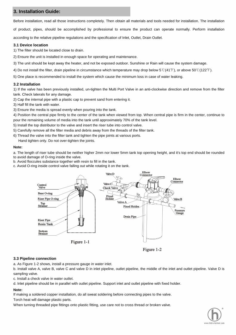
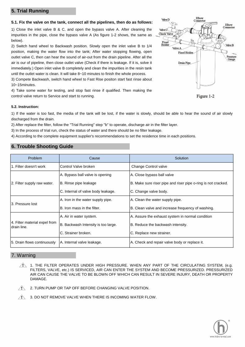
a. As Figure 1-2 shows, install a pressure gauge in water inlet.
b. Install valve A, valve B, valve C and valve D in inlet pipeline, outlet pipeline, the middle of the inlet and outlet pipeline. Valve D is
sampling valve.
c. Install a check valve in water outlet.
d. Inlet pipeline should be in parallel with outlet pipeline. Support inlet and outlet pipeline with fixed holder.
If making a soldered copper installation, do all sweat soldering before connecting pipes to the valve.
Torch heat will damage plastic parts.
When turning threaded pipe fittings onto plastic fitting, use care not to cross thread or broken valve.
3. Installation Guide:
1) The filter should be located close to drain.
2) Ensure the unit is installed in enough space for operating and maintenance.
3) The unit should be kept away the heater, and not be exposed outdoor. Sunshine or Rain will cause the system damage.
4) Do not install the filter, drain pipeline in circumstance which temperature may drop below 5℃(41℉), or above 50℃(122℉).
5) One place is recommended to install the system which cause the minimum loss in case of water leaking.
a. The length of riser tube should be neither higher 2mm nor lower 5mm tank top opening height, and it's top end should be rounded
to avoid damage of O-ring inside the valve.
b. Avoid floccules substance together with resin to fill in the tank.
c. Avoid O-ring inside control valve falling out while rotating it on the tank.
Before installation, read all those instructions completely. Then obtain all materials and tools needed for installation. The installation
of product, pipes, should be accomplished by professional to ensure the product can operate normally. Perform installation
according to the relative pipeline regulations and the specification of Inlet, Outlet, Drain Outlet.
1) If the valve has been previously installed, un-tighten the Multi Port Valve in an anti-clockwise direction and remove from the filter
tank. Check laterals for any damage.
2) Cap the internal pipe with a plastic cap to prevent sand from entering it.
3) Half fill the tank with water.
3) Ensure the media is spread evenly when pouring into the tank.
4) Position the central pipe firmly to the center of the tank when viewed from top. When central pipe is firm in the center, continue to
pour the remaining volume of media into the tank until approximately 70% of the tank level.
5) Install the top distributor to the valve and insert the riser tube into control valve.
5) Carefully remove all the filter media and debris away from the threads of the filter tank.
6) Thread the valve into the filter tank and tighten the pipe joints at various ports.
Hand tighten only. Do not over-tighten the joints.
3.4 Install drain pipeline
Directly connect the outlet with the rigid pipeline, such as UPVC, etc.
Note:
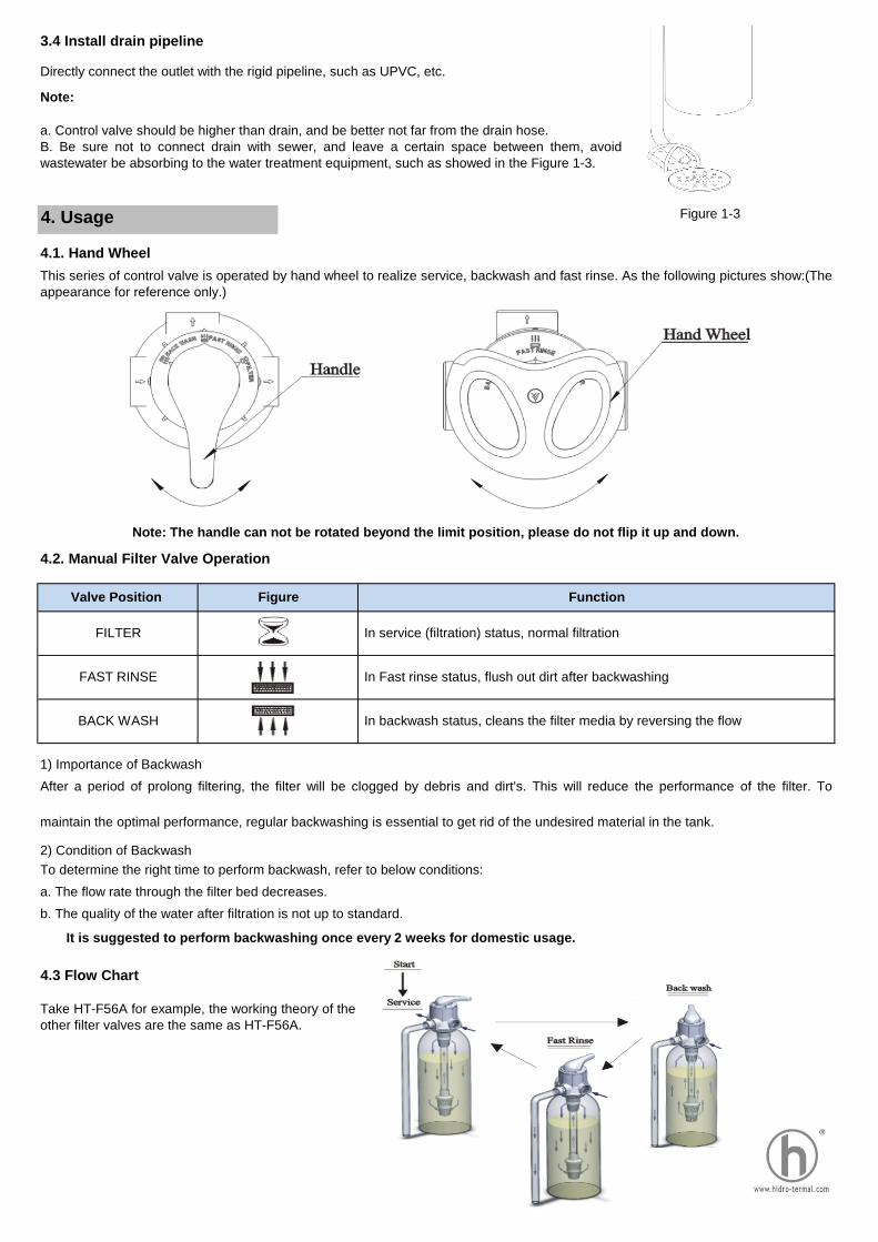
4.1. Hand Wheel
4.2. Manual Filter Valve Operation
1) Importance of Backwash
To determine the right time to perform backwash, refer to below conditions:
a. The flow rate through the filter bed decreases.
b. The quality of the water after filtration is not up to standard.
4.3 Flow Chart
In Fast rinse status, flush out dirt after backwashing
BACK WASH In backwash status, cleans the filter media by reversing the flow
This series of control valve is operated by hand wheel to realize service, backwash and fast rinse. As the following pictures show:(The
appearance for reference only.)
4. Usage
a. Control valve should be higher than drain, and be better not far from the drain hose.
B. Be sure not to connect drain with sewer, and leave a certain space between them, avoid
wastewater be absorbing to the water treatment equipment, such as showed in the Figure 1-3.
Note: The handle can not be rotated beyond the limit position, please do not flip it up and down.
Take HT-F56A for example, the working theory of the
other filter valves are the same as HT-F56A.
Valve Position Figure Function
FILTER In service (filtration) status, normal filtration
After a period of prolong filtering, the filter will be clogged by debris and dirt's. This will reduce the performance of the filter. To
maintain the optimal performance, regular backwashing is essential to get rid of the undesired material in the tank.
2) Condition of Backwash
It is suggested to perform backwashing once every 2 weeks for domestic usage.
FAST RINSE
Figure 1-3
5. Trial Running
5.1. Fix the valve on the tank, connect all the pipelines, then do as follows:
5.2. Instruction:
7. Warning
1) If the water is too fast, the media of the tank will be lost, if the water is slowly, should be able to hear the sound of air slowly
discharged from the drain.
2) After replace the filter, follow the "Trial Running" step "b" to operate, discharge air in the filter layer.
3) In the process of trial run, check the status of water and there should be no filter leakage.
4) According to the complete equipment supplier's recommendations to set the residence time in each positions.
1) Close the inlet valve B & C, and open the bypass valve A. After cleaning the
impurities in the pipe, close the bypass valve A (As figure 1-2 shows, the same as
below).
2) Switch hand wheel to Backwash position. Slowly open the inlet valve B to 1/4
position, making the water flow into the tank; After water stopping flowing, open
outlet valve C, then can hear the sound of air-out from the drain pipeline. After all the
air is our of pipeline, then close outlet valve (Check if there is leakage. If it is, solve it
immediately.) Open inlet valve B completely and clean the impurities in the resin tank
until the outlet water is clean. It will take 8~10 minutes to finish the whole process.
3) Compete Backwash, switch hand wheel to Fast Rise positon start fast rinse about
10~15minutes.
4) Take some water for testing, and stop fast rinse if qualified. Then making the
control valve return to Service and start to running.
6. Trouble Shooting Guide
Problem Cause Solution
1. Filter doesn't work Control Valve broken Change Control valve
2. Filter supply raw water.
A. Bypass ball valve is opening A. Close bypass ball valve
B. Rinse pipe leakage B. Make sure riser pipe and riser pipe o-ring is not cracked.
C. Internal of valve body leakage. C. Change valve body.
B. Backwash Intensity is too large. B. Reduce the backwash intensity.
C. Strainer broken. C. Replace new strainer.
3. Pressure lostA. Iron in the water supply pipe. A. Clean the water supply pipe.
B. Iron mass in the filter. B. Clean valve and increase frequency of washing.
1. THE FILTER OPERATES UNDER HIGH PRESSURE. WHEN ANY PART OF THE CIRCULATING SYSTEM, (e.g.
FILTERS, VALVE, etc.) IS SERVICED, AIR CAN ENTER THE SYSTEM AND BECOME PRESSURIZED. PRESSURIZED
AIR CAN CAUSE THE VALVE TO BE BLOWN OFF WHICH CAN RESULT IN SEVERE INJURY, DEATH OR PROPERTY
DAMAGE.
2. TURN PUMP OR TAP OFF BEFORE CHANGING VALVE POSITION.
3. DO NOT REMOVE VALVE WHEN THERE IS INCOMING WATER FLOW.
5. Drain flows continuously A. Internal valve leakage. A. Check and repair valve body or replace it.
4. Filter material expel from
drain line.
A. Air in water system. A. Assure the exhaust system in normal condition

8. Valve Body Components
Key No. Product Description Qty
1 O-ring 1
2 O-ring 1
Valve Body (ABS + GF10) 1
Valve Body (PPO + GF20) 1
4 Plastic Pin 2
5 Seal Ring 1
6 Fixed Disk 1
7 Moving Disk 1
8 Shaft 1
9 Anti-friction Washer 1
10 O-ring 1
11 O-ring 1
12 Fitting Nut 1
13 O-ring 1
14 Decorative Cover 1
15 Decorative Button 1
Handle (Metal)
Handle (Plastic)
Item No. Product Description Qty
1 O-ring 1
2 O-ring 1
3 Valve Body 1
4 Screw, Cross 2
5 Seal Ring 1
6 Fixed Disk 1
7 Moving Disk 1
8 Shaft 1
9 Anti-friction Washer 1
10 O-ring 1
11 O-ring 1
12 Fitting Nut 1
13 O-ring 1
14 Decorative Cover 1
15 Handle 1
16 Screw, Cross 1
17 Brand 1
16 1
8.2 Valve Replacement Parts-HT-F56D
8.1 Valve Replacement Parts-HT-F56A
3

9. Manual Filter Valve Packing list
When open the valve box, please check the following parts.
1) HT-F56A Valve
Description Picture Quantity Remark
Control Valve 1PC This picture is for reference only
User Manual 1PC
Base Seal Ring(73*5.3) 1PC
1" Washer
(φ30*φ24*3.3)3PCS
2) HT-F56D Valve
Description Picture Quantity Remark
Control Valve 1PC This picture is for reference only
User Manual 1PC
Base Seal Ring
(104.6*5.7)1PC
Threaded Top Strainer
Connector3PCS
Tapping Screw
ST3.9*195PCS
Spare parts Kit include following parts
Spare parts Kit include following parts