Embed Size (px)
Citation preview
By - Prof.: D. R. LUHAR
Computer Communication Study Guide Series Books
SIGMA TRAINING INSTITUTEBasement, Hindola Complex,Lad-Society Road, Near Vastrapur Lake,Vastrapur,AHMEDABAD-380 015. INDIA
Phone 079-26852427Fax 079-26840290
E-mail [email protected] www.sigmatrg.com
Price Rs. 200/-
Topic - 1200
Introduction to Public Switched Telephone Networks (PSTNs)
POTS, ISDN, DLC, DSL, and PON Technologies, Systems and Services
Sigma Publishing
Table of Contents
OVERVIEW . . . . . . . . . . . . . . . . . . . . . . . . . . . . . . . . . . . . . . . . . . 3
LOCAL LOOP . . . . . . . . . . . . . . . . . . . . . . . . . . . . . . . . . . . . . . . . . . 3SWITCHING SYSTEMS . . . . . . . . . . . . . . . . . . . . . . . . . . . . . . . . . . . . 5TRANSMISSION SYSTEMS . . . . . . . . . . . . . . . . . . . . . . . . . . . . . . . . . . 7NUMBERING PLAN . . . . . . . . . . . . . . . . . . . . . . . . . . . . . . . . . . . . . . 7CALL PROCESSING . . . . . . . . . . . . . . . . . . . . . . . . . . . . . . . . . . . . . 10
MARKET GROWTH . . . . . . . . . . . . . . . . . . . . . . . . . . . . . . . . . . 10
VOICE SERVICE . . . . . . . . . . . . . . . . . . . . . . . . . . . . . . . . . . . . . . . 10DATA SERVICE . . . . . . . . . . . . . . . . . . . . . . . . . . . . . . . . . . . . . . . . 12
TECHNOLOGIES . . . . . . . . . . . . . . . . . . . . . . . . . . . . . . . . . . . . 13
PUBLIC TELEPHONE SYSTEM INTERCONNECTION . . . . . . . . . . . . . . . 13POTS (dial) Line Connections . . . . . . . . . . . . . . . . . . . . . . . . .14Direct Inward Dialing (DID) Connections . . . . . . . . . . . . . . . .14Foreign Exchange Office (FXO) . . . . . . . . . . . . . . . . . . . . . . . . .14Foreign Exchange Station (FXS) . . . . . . . . . . . . . . . . . . . . . . . .14Type 1 Connections . . . . . . . . . . . . . . . . . . . . . . . . . . . . . . . . . .15
Integrated Services Digital Network - Basic Rate InterfaceConnections (ISDN-BRI) . . . . . . . . . . . . . . . . . . . . . . . . . . . . . .15
Integrated Services Digital Network - Primary Rate InterfaceConnections . . . . . . . . . . . . . . . . . . . . . . . . . . . . . . . . . . . . . . . .16Type 2A Connections . . . . . . . . . . . . . . . . . . . . . . . . . . . . . . . . .16Type 2B Connections . . . . . . . . . . . . . . . . . . . . . . . . . . . . . . . . .16Type 2C Connections . . . . . . . . . . . . . . . . . . . . . . . . . . . . . . . . .17Type 2D Connections . . . . . . . . . . . . . . . . . . . . . . . . . . . . . . . . .17Type S Connections . . . . . . . . . . . . . . . . . . . . . . . . . . . . . . . . . .17
COMMON CHANNEL SIGNALING (SS7) . . . . . . . . . . . . . . . . . . . . . . . 19
-v-
SS7 AND INTERNET PROTOCOL (IP) SIGNALING SYSTEMS . . . . . . . . . 21ADVANCED INTELLIGENT NETWORKS (AIN) . . . . . . . . . . . . . . . . . . . 22
SYSTEMS . . . . . . . . . . . . . . . . . . . . . . . . . . . . . . . . . . . . . . . . . . 24
PLAIN OLD TELEPHONE SERVICE (POTS) . . . . . . . . . . . . . . . . . . . . 24INTEGRATED DIGITAL SERVICES NETWORK (ISDN) . . . . . . . . . . . . . 25DIGITAL SUBSCRIBER LINE (DSL) . . . . . . . . . . . . . . . . . . . . . . . . . . 27DIGITAL LOOP CARRIER (DLC) . . . . . . . . . . . . . . . . . . . . . . . . . . . . 29PASSIVE OPTICAL NETWORK (PON) . . . . . . . . . . . . . . . . . . . . . . . . 32
SERVICES . . . . . . . . . . . . . . . . . . . . . . . . . . . . . . . . . . . . . . . . . . 33
VOICE . . . . . . . . . . . . . . . . . . . . . . . . . . . . . . . . . . . . . . . . . . . . . . 33CENTREX . . . . . . . . . . . . . . . . . . . . . . . . . . . . . . . . . . . . . . . . . . . . 35FRAME RELAY SERVICE . . . . . . . . . . . . . . . . . . . . . . . . . . . . . . . . . 35LEASED LINES . . . . . . . . . . . . . . . . . . . . . . . . . . . . . . . . . . . . . . . . 37DIGITAL SUBSCRIBER LINE (DSL) . . . . . . . . . . . . . . . . . . . . . . . . . . 38
FUTURE ENHANCEMENTS . . . . . . . . . . . . . . . . . . . . . . . . . . . 39
PACKETIZED VOICE . . . . . . . . . . . . . . . . . . . . . . . . . . . . . . . . . . . . 39HIGH-SPEED MULTIMEDIA SERVICES . . . . . . . . . . . . . . . . . . . . . . . . 40FIBER DISTRIBUTION NETWORKS . . . . . . . . . . . . . . . . . . . . . . . . . . . 40SOFTSWITCHES . . . . . . . . . . . . . . . . . . . . . . . . . . . . . . . . . . . . . . . . 41REFERENCES . . . . . . . . . . . . . . . . . . . . . . . . . . . . . . . . . . . . . . . . . 42
-vi-
-1-
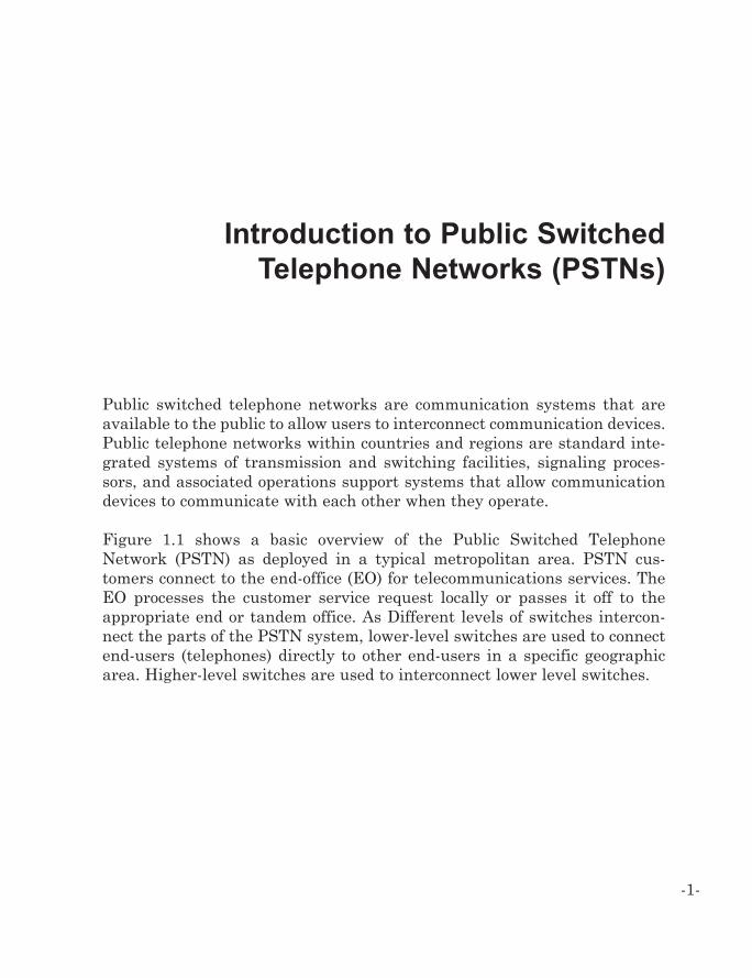
Introduction to Public SwitchedTelephone Networks (PSTNs)
Public switched telephone networks are communication systems that areavailable to the public to allow users to interconnect communication devices.Public telephone networks within countries and regions are standard inte-grated systems of transmission and switching facilities, signaling proces-sors, and associated operations support systems that allow communicationdevices to communicate with each other when they operate.
Figure 1.1 shows a basic overview of the Public Switched TelephoneNetwork (PSTN) as deployed in a typical metropolitan area. PSTN cus-tomers connect to the end-office (EO) for telecommunications services. TheEO processes the customer service request locally or passes it off to theappropriate end or tandem office. As Different levels of switches intercon-nect the parts of the PSTN system, lower-level switches are used to connectend-users (telephones) directly to other end-users in a specific geographicarea. Higher-level switches are used to interconnect lower level switches.
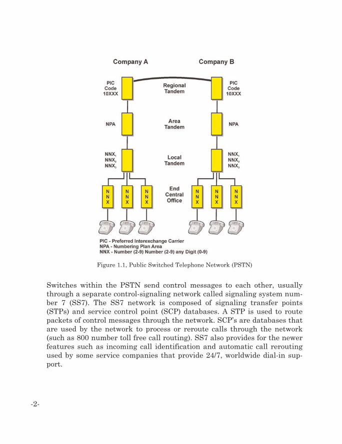
Switches within the PSTN send control messages to each other, usuallythrough a separate control-signaling network called signaling system num-ber 7 (SS7). The SS7 network is composed of signaling transfer points(STPs) and service control point (SCP) databases. A STP is used to routepackets of control messages through the network. SCP’s are databases thatare used by the network to process or reroute calls through the network(such as 800 number toll free call routing). SS7 also provides for the newerfeatures such as incoming call identification and automatic call reroutingused by some service companies that provide 24/7, worldwide dial-in sup-port.
-2-
Figure 1.1, Public Switched Telephone Network (PSTN)
Overview
Public telephone networks include local loops (access lines), switching sys-tems, transmission systems, databases (such as numbering plans) and callprocessing software and hardware (computers). These systems are central-ly coordinated by network management systems.
Post, telephone, and telegraph (PTT) and local exchange carriers (LEC’s) arethe established telephone network operators or companies that provide localtelecommunications services. For some countries, PTTs are governmentoperated telephone systems. In the United States, LEC’s are granted fran-chises to provide telephone services to certain geographical areas as man-dated by the Federal Communication Commission (FCC). Recently, deregu-lation and privatization of telecommunication systems worldwide haveallowed the creation of new competing local exchange carriers (CLECs).CLEC’s provide similar services as LEC’s and PTTs. In some cases, CLECsprovide services by leasing existing lines from incumbent local exchangecarriers (ILECs) and reselling services on these lines. In other cases, CLECsinstall new communication lines or provide connection by wireless service.
Local Loop
The local loop is the connection (wireless or wired) between a customer’stelephone or data equipment and a LEC or other telephone service provider.Traditionally, the local loop (also called “outside plant” or the “last mile”)has been composed of copper wires that extend from the EO switch. The EOis the last switching office in the telephone network that connects customersto the telephone network.
The EO switch cables meet the copper (or other types of lines) at the maindistribution frame (MDF). The MDF is a wiring rack that allows techniciansto splice the local loop lines with the lines from the switching system. Localloop lines leave the MDF in bundles (possibly thousands of wires in eachbundle) and arrive in other junction points such as local distribution frames(LDF). The LDF allows the connection of the final connection (the “drop”) to
-3-
the business or residence. At the entry to the customer’s location, there isoften a network termination (NT) device that isolates the telephone networkfrom the wiring inside the customers building.
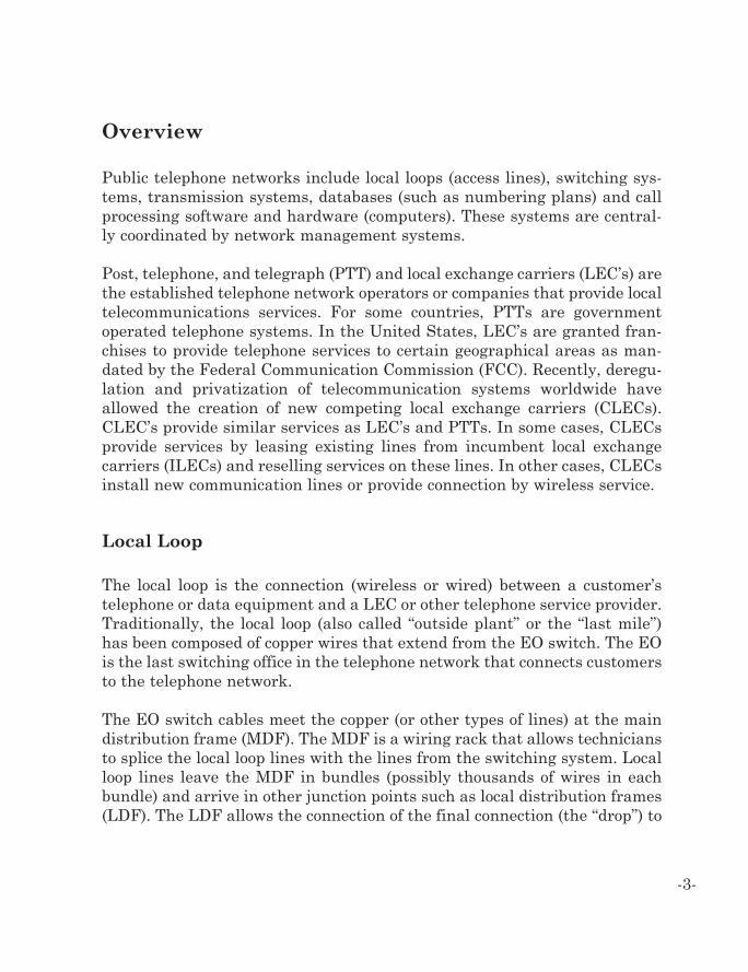
Figure 1.2 depicts a traditional local loop distribution system. This diagramshows a central office (CO) building that contains an EO switch. The EOswitch is connected to the MDF splice box. The MDF connects the switch tobundles of cables in the “outside plant” distribution network. These bundlesof cables periodically are connected to local distribution frames (LDFs). TheLDFs allow connection of the final cable (called the “drop”) that connects tothe house or building. A NT block isolates the inside wiring from the tele-phone system. Twisted pair wiring is usually looped through the home orbuilding to provide several telephone connection points, or jacks, so tele-phones can connect to the telephone system.
-4-
Figure 1.2, Local Loop
Switching Systems
Switching systems are assemblies of equipment that setup, maintain, anddisconnect connections between multiple communication lines. Switchingsystems are often classified by the type of network they are part of (e.g.,packet or circuit switched) and by the methods that are used to control theswitches. The term “switch” is sometimes used as a short name for switch-ing system. Public telephone switching systems have many switches withintheir network. A typical switch can handle up to 10,000 communication lineseach.
Early switches used mechanical levers (crossbars) to interconnect lines.Modern switches use computer systems to dynamically setup, maintain, anddisconnect communication paths through one or more switches. True com-puter-based switching came about through the introduction of the electron-ic switching systems (ESS’s). ESS EOs did not require a physical connectionbetween incoming and outgoing circuits. Paths between the circuits consist-ed of temporary memory locations that allowed for the temporary storage oftraffic. For an ESS system, a computer controls the assignment, storage,and retrieval of memory locations so that a portion of an incoming line (timeslot) could be stored in temporary memory and retrieved for insertion to anoutgoing line. This is called a time slot interchange (TSI) memory matrix.The switch control system maps specific time slots on an incoming commu-nication line (e.g., DS3) to specific time slots on an outgoing communicationline.
The public telephone network switching system architecture typically usesa distributed switching system that has a hierarchy structure of switchinglevels. The use of distributed switching systems allows calls in the same geo-graphic area to be connected to each other by the nearest switching system.Centralized switching systems require that all calls be connected through asingle switch, even if the switch was located a long distance away from thecallers. The use of distributed network architecture PSTN systems alsoallows for reduced call processing requirements at each switch. Using a mul-tilevel hierarchy structure for switching systems (such as local switchedinterconnected by long distance switches) allows switching to occur at lower
-5-
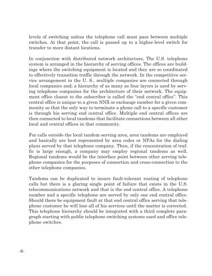
levels of switching unless the telephone call must pass between multipleswitches. At that point, the call is passed up to a higher-level switch fortransfer to more distant locations.
In conjunction with distributed network architecture, The U.S. telephonesystem is arranged in the hierarchy of serving offices. The offices are build-ings where the switching equipment is located and they are so coordinatedto effectively transition traffic through the network. In the competitive ser-vice arrangement in the U. S., multiple companies are connected throughlocal companies and; a hierarchy of as many as four layers is used by serv-ing telephone companies for the architecture of their network. The equip-ment office closest to the subscriber is called the “end central office”. Thiscentral office is unique to a given NNX or exchange number for a given com-munity so that the only way to terminate a phone call to a specific customeris through his serving end central office. Multiple end central offices arethen connected to local tandems that facilitate connections between all otherlocal and central offices in that community.
For calls outside the local tandem serving area, area tandems are employedand basically are best represented by area codes or NPAs for the dialingplans served by that telephone company. Then, if the concentration of traf-fic is large enough, a company may employ regional tandems as well.Regional tandems would be the interface point between other serving tele-phone companies for the purposes of connection and cross-connection to theother telephone companies.
Tandems can be duplicated to insure fault-tolerant routing of telephonecalls but there is a glaring single point of failure that exists in the U.S.telecommunications network and that is the end central office. A telephonenumber and a specific telephone are served by only one end central office.Should there be equipment fault at that end central office serving that tele-phone customer he will lose all of his services until the matter is corrected.This telephone hierarchy should be integrated with a third complete para-graph starting with public telephone switching systems used and office tele-phone switches.
-6-

Transmission Systems
Transmission systems interconnect communication devices to each other byguiding signal energy in a particular direction or directions through a trans-mission medium such as copper, air, or glass. A transmission system willhave at least one transmitting device, a transmission medium, and a receiv-ing device. The transmitting communication devices is capable of convertinginformation into form electrical, electromagnetic wave (radio), or optical sig-nals that allows the information to be transferred through the medium. Thereceiving communication device converts the transmitted signal into anoth-er form that can be used by the device or other devices that are connected toit. Transmission systems can be unidirectional (one direction) or they can bebi-directional (two directions). Transmission systems can provide for a sin-gle channel on a single line (possibly an analog telephone line) or the trans-mission system may combine many communication channels onto a singlecommunication line (such as a high-speed digital line).
Numbering Plan
A numbering plan is a system that identifies communication points withina communications network through the structured use of numbers. Thestructure of the numbers is divided to indicate specific regions or groups ofusers. It is important that all users connected to a telephone network agreeon a specific numbering plan to be able to identify and route calls from onepoint to another.
Telephone numbering plans throughout the world and systems vary dra-matically. In some countries, it is possible to dial using 5 digits and othersrequire 10 digits. To uniquely identify every device that is connected to pub-lic telephone networks, the Comite Consultatif Internationale deTelegraphique et Telephonique (CCITT) devised a world numbering planthat provides codes for telephone access to each country. These are calledcountry codes. Coupled with the national telephone number assigned toeach subscriber in a country, the country code telephone makes that sub-
-7-
scribers number unique worldwide. The International TelecommunicationsUnion (ITU) administers the World Numbering Plan standard E.164 pub-lishes any new standards or modifications to existing standards on theInternet.
Each country defines its public telephone network numbering plans. TheUnited States and Canada adopted the North American Numbering Plan(NANP) that allows the two countries to appear as one when dialing inter-nally. Each country has a country code prescribed by the World NumberingPlan so they are accessed internationally as separate entities. The NANP isbased on 10 digit numbering (NXX-NXX-XXXX). The number consists of a 3-digit area code, a 3-digit central office code, and a 4-digit line number. Thefirst three digits (NXX) are the Numbering Plan Area (NPA) or area code. Itis this 3-digit code that designates one of the numbering plan areas in theNorth American Numbering Plan for direct distance dialing. Originally, theformat was N0/1X, where N is any digit 2 through 9 and X is any digit. From1995 on, the acceptable format is NXX.
Figure 1.3 shows the world (telephone) numbering plan recommendation,“E.164” developed by the International Telecommunications Union (ITU).This diagram shows the numbering plan divides a telephone number into acountry code (CC), national destination code (NDC), and subscriber number(SN) for telephone numbering. The CC consists of one, two or three digitsand the first digit identifies the world zone. This diagram shows that thelocal number can be divided into an exchange code (end office switch identi-fier) and a port (or extension) code.
-8-
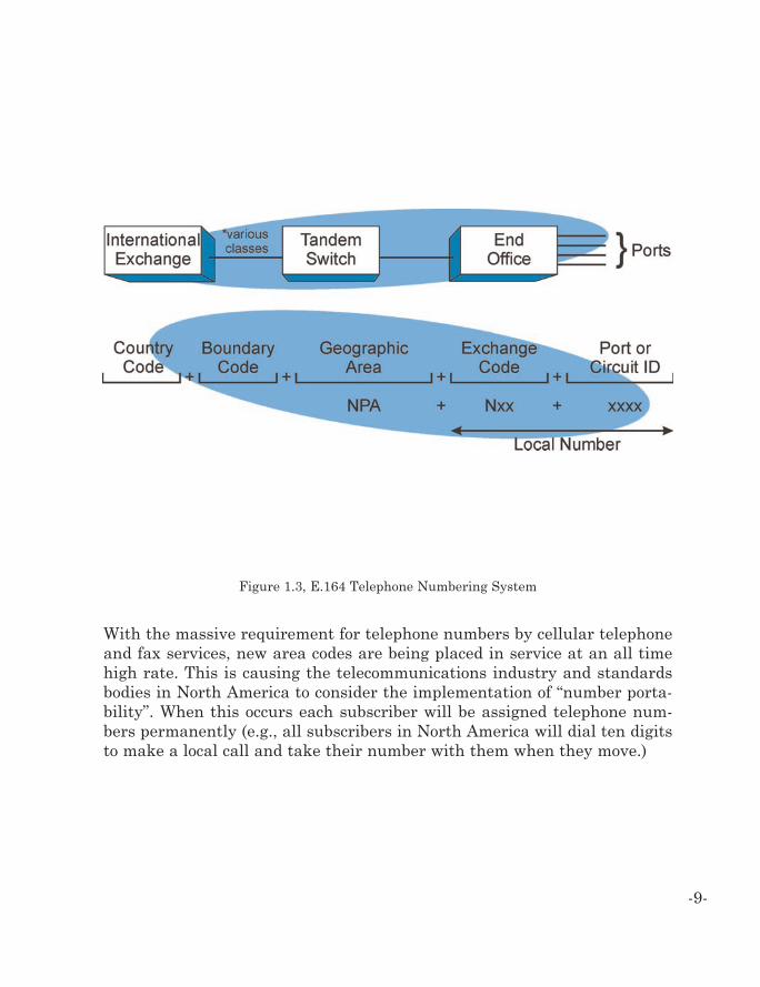
With the massive requirement for telephone numbers by cellular telephoneand fax services, new area codes are being placed in service at an all timehigh rate. This is causing the telecommunications industry and standardsbodies in North America to consider the implementation of “number porta-bility”. When this occurs each subscriber will be assigned telephone num-bers permanently (e.g., all subscribers in North America will dial ten digitsto make a local call and take their number with them when they move.)
-9-
Figure 1.3, E.164 Telephone Numbering System
Call Processing
Call processing is the steps that occur during the length of a call. Thesesteps are typically associated with the routing and control of the call. Whenused as part of a telephone system, call processing involves gathering andprocessing information from various sources such as capturing the dialeddigits entered by a user of a telephone or storing the connection informationfrom a switching system that will be used for billing records. There may bemany parts of the PSTN (software and hardware) that perform call process-ing functions including the switch that connects a telephone to a telephonenumber database (SCP) that can translate a toll free/freephone telephonenumber into a number of the destination telephone.
Market Growth
Between 1995 and 2002, the number of wired telephone lines in the worldincreased from 689 million to 1.1 billion [1]. While the number of new wiredtelephone lines continues to increase in developing nations, the growth ofwired telephone lines in some countries are decreasing due to the increasein the number of wireless (mobile) telephone lines. Existing (incumbent)local telephone companies are also experiencing new competition. In theUnited States, of the 192 million telephone lines in use in 2002, 173 millionwere provided by LECs (~79%), 19.7 million were provided by CLECs(~20%), and 2.1 million were provided by cable-television/telephony (~1%)[2]. In mid 2000, telephone voice traffic (measured in minutes) on wired tele-phone systems began to decline for the first time [3].
Voice Service
Voice telephone service is any service or feature accessible through theLEC/CLEC or IXC that can be accessed via a standard analog or digitaltelephone lines. The key reasons for growth in the number of telephone linesinclude dial-up Internet access, fax telephone lines, and mobile telecommu-nications.
-10-
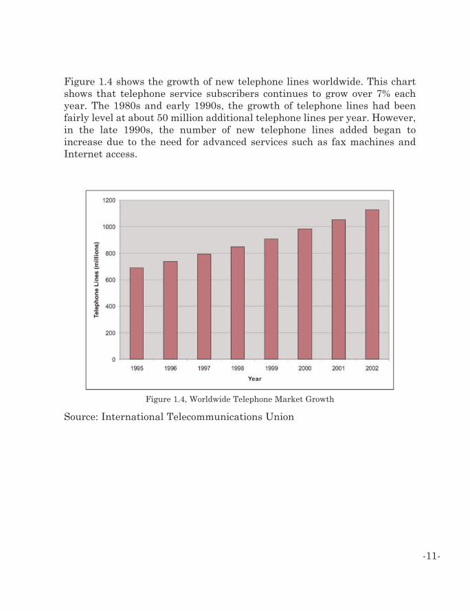
Figure 1.4 shows the growth of new telephone lines worldwide. This chartshows that telephone service subscribers continues to grow over 7% eachyear. The 1980s and early 1990s, the growth of telephone lines had beenfairly level at about 50 million additional telephone lines per year. However,in the late 1990s, the number of new telephone lines added began toincrease due to the need for advanced services such as fax machines andInternet access.
-11-
Figure 1.4, Worldwide Telephone Market Growth
Source: International Telecommunications Union
Data Service
Data service is the act of moving data through a network from one datasource to another. Generally these sources are computers and they interfacewith the network via modems or channel service units (CSU’s). Data trans-fers can occur over dialed voice connections or via dedicated lines such asDSL services and dedicated T1 services and over cable TV infrastructure.
In 2002, the number of customers that use the Internet was increasing at arate of nearly 40% a year while data traffic on the Internet (amount of dataper user) is expanding at a rate of over 100% per year. The amount of datathat was transferred over the Internet in the United States in 2000 aver-aged 27,500 terabytes (1,000 billion bytes) per month [3]. The data trans-mission on private networks grew 500% between 1997 and 2000 with anaverage of 3,000 terabytes per month transferred in the United States [4].
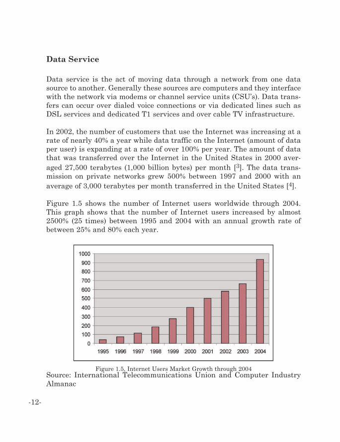
Figure 1.5 shows the number of Internet users worldwide through 2004.This graph shows that the number of Internet users increased by almost2500% (25 times) between 1995 and 2004 with an annual growth rate ofbetween 25% and 80% each year.
-12-
Figure 1.5, Internet Users Market Growth through 2004Source: International Telecommunications Union and Computer IndustryAlmanac
Technologies
Some of the key technologies behind the operation of the public telephonenetwork include interconnection lines, network common control signaling,and intelligent call processing. Several types of interconnection systems areused to provide access to different services and systems available throughthe PSTN. To coordinate the overall operation of the PSTN, a standard com-mon control signaling (CCS) system is typically used. The use of intelligentcall processing can combines the use of efficient high-speed interconnectionlines with common control signaling to provide for advanced services suchas call forwarding, telephone number portability, and prepaid services.
Public Telephone System Interconnection
There are many types of interconnection options available to connect publictelephone systems to other public telephone networks or private telephonenetworks. The type of connection selected depends on the type of private sys-tem, telecommunications regulations, and the needs of the company thatuses the private telephone system (e.g., advanced calling features). In addi-tion to standard telephone system connection types, there are also private-line connections that may be used to link private branch exchange PBX sys-tems together.
There are two types of connections that are used between switching sys-tems: line side and trunk side. Line side connections are an interconnectionline between the customer’s equipment and the last switch EO in the tele-phone network. The line side connection isolates the customer’s equipmentfrom network signaling requirements. Line side connections are usually lowcapacity (one channel) lines. Trunk side connections are used to intercon-nect telephone network switching systems to each other. Trunk side con-nections are usually high capacity lines. Primary rate interfaces use out-of-band signaling in a dedicated signaling channel.
-13-
-14-
POTS (dial) Line Connections
POTS dial lines are 2-wire, basic line-side connections from an EO with lim-ited signaling capability. Because dial lines are line-side connections, callsetup time may be longer than those connections that employ trunk-sidesupervision.
Direct Inward Dialing (DID) Connections
Direct inward dialing (DID) connections are trunk-side (network side) EOconnections. The network signaling on these 2-wire circuits is primarily lim-ited to one-way, incoming service. DID connections employ different super-vision and address pulsing signals than dial lines. Typically, DID connec-tions use a form of loop supervision called reverse battery, which is commonfor one-way, trunk-side connections. Until recently, most DID trunks wereequipped with either dial pulse (DP) or dual tone multifrequency (DTMF)address pulsing. While many wireless carriers would have preferred to usemultifrequency (MF) address pulsing, a number of LEC’s prohibited the useof MF on DID trunks.
Foreign Exchange Office (FXO)
Foreign exchange office (FXO) is an interface or channel unit that allows ananalog connection (foreign exchange circuit) to be directed at the PSTN’scentral office or to a station interface on a PBX. The FXO sits on the switchend of the connection. It plugs directly into the line side of the switch so theswitch thinks the FXO interface is a telephone. (See also: foreign exchangestation.)
Foreign Exchange Station (FXS)
Foreign exchange station is a type of channel unit used at the subscriberstation end of a foreign exchange circuit. A foreign exchange station (FXS)interface connects directly to a standard telephone, fax machine, or similardevice and supplies ring, voltage, and dial tone. (See also: foreign exchangeoffice.)
-15-
Type 1 Connections
Type 1 connections are trunk-side connections to an EO. The EO uses atrunk-side signaling protocol in conjunction with a feature known as TrunkWith Line Treatment (TWLT). This connection was originally described intechnical advisory 76 published by AT&T in 1981. This interconnection wasdeveloped because dial line and DID connections did not provide enough sig-naling information to allow the connection of public telephone networks toother types of networks (such as wireless and PBX networks). The switchmust be equipped to provide TWLT, or its equivalent to offer Type 1 service.As a result, type 1 is not universally available. The TWLT feature allows theEO to combine some line-side and trunk-side features. For example, whiletrunk-side signaling protocols are used, the calls are recorded for billingpurposes as if they were made by a line-side connection.
Type 1 connections are usually used as 2-way trunks. Two-way trunks are4-wire circuits, meaning they have separate transmit and receive paths, andalmost always use MF address pulsing and supervision. The address puls-ing normally uses wink-start control. One-way Type 1 connections can beprovided on a 2-wire basis using E&M supervision or reverse battery likethe DID connection. T1 connections in a digital context are also providedand these are labeled as T1 services. These T1 services include in-band sig-naling as well as out-of-band signaling in the later described services of pri-mary interface.
Integrated Services Digital Network - Basic Rate InterfaceConnections (ISDN-BRI)
ISDN-BRI connection provides two bearer channels, each using a 64 kbpsdigital channel, as well as a 16 kbps data link for signaling messages. This144 kbps combination is referred to as 2B+D, which signifies two bearerchannels and one data channel. The bearer channels provide the voice por-tion while the data channel is used to transfer SS7 signaling messages. EOswitches must have an ISDN-BRI interface and software installed to supplythis connection.
Integrated Services Digital Network - Primary Rate InterfaceConnections
Another variation of Type 1 is the Integrated Services Digital Network -Primary Rate Interface (ISDN-PRI). It has capabilities similar to the ISDN-BRI but employs 23 bearer channels and one signaling channel, or a 23B+Dconfiguration. The ISDN-PRI interconnection is provided using a standardDS1-level interface that would normally provide the equivalent of 24 voicechannels. It offers the same calling capabilities as noted for the Type 1 andISDN-BRI connections. Primary rate interfaces use out-of-band signaling ina dedicated signaling channel.
Type 2A Connections
Type 2A connections are true trunk-side connections that employ trunk-sidesignaling protocols. Typically, they are two-way connections that are 4-wirecircuits using E&M supervision with multifrequency (MF) address pulsing.The address pulsing is almost always under wink-start control. Type 2Aconnections allow the other public or private telephone network switchingsystems to connect to the PSTN and operate like any other EO.
Type 2A connections may restrict calls to specific NXX (exchange) codes andaccess to operator services (phone number directories, emergency calls,freephone/toll free) may not be permitted. For some interconnections, addi-tional connections (such as a type 1) may be used to supplement the type 2Aconnection to allow access to other operator or network services.
Type 2B Connections
Type 2B connections are high usage trunk groups that are used betweenEOs within the same system. The type 2B connection can be used in con-junction with the Type 2A. When a type 2B is used, the first choice of rout-ing is through a Type 2B with overflow through the type 2A. Because thetype 2B connection is used for high usage connections, it can access onlyvalid NXX codes of the EO providing that it is connected to. Type 2B con-nections are almost always 4-wire, two-way connections that use E&Msupervision and multifrequency (MF) address pulsing.
-16-
Type 2C Connections
Type 2C connections were developed to allow direct connection to publicsafety centers (E911) via a tandem or local tandem switch. This intercon-nection type must provide additional information such as the return phonenumber (complicated on mobile telephone systems) and the location of thecaller. This information is passed on to a public safety answering point(PSAP). In recent times primary rate interface has been a more popular con-nection for the purposes of enhanced 911 services and the appropriate pub-lic safety answering points. Because of the outer band signaling and the ded-icated channel for signaling and the PRI connection has become more flexi-ble and versatile to meet the needs of an enhanced 911 service offering.
Type 2D Connections
Type 2D interconnection lines allow direct connection from an operator ser-vices system (OSS) switch. The OSS switch is a special tandem that containsadditional call processing capabilities that enables operator services specialdirectory assistance services. The type 2D connection also forwards theautomatic number identification information to allow proper billing recordsto be created. Type 2D connection will normally use trunks employing E&Msignaling with wink start, and multifrequency (MF) address pulsing.
Type S Connections
Type S connections transfer signaling messages that are associated withother interconnection types (out-of-band signaling). The type S is a data link(e.g., 56 kbps) that is used to connect the signaling interfaces betweenswitches. Type S connections permit additional features to be supported bythe network such as finding and using call forwarding telephone numbers.Because type S connections cost money, some smaller public telephone net-works do not offer or use type S connections.
-17-
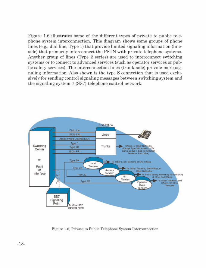
Figure 1.6 illustrates some of the different types of private to public tele-phone system interconnection. This diagram shows some groups of phonelines (e.g., dial line, Type 1) that provide limited signaling information (line-side) that primarily interconnect the PSTN with private telephone systems.Another group of lines (Type 2 series) are used to interconnect switchingsystems or to connect to advanced services (such as operator services or pub-lic safety services). The interconnection lines (trunk-side) provide more sig-naling information. Also shown is the type S connection that is used exclu-sively for sending control signaling messages between switching system andthe signaling system 7 (SS7) telephone control network.
-18-
Figure 1.6, Private to Public Telephone System Interconnection
Common Channel Signaling (SS7)
The signaling system #7 (SS7) is an international standard network signal-ing protocol that allows common channel (independent) signaling betweentelephone network elements. SS7 system protocols are optimized for tele-phone system control connections and they are only directly accessible totelephone network operators.
Common channel signaling (CCS) is a separate signaling system that sepa-rates content of telephone calls from the information used to set up the call(signaling information). When call-processing information is separated fromthe communication channel, it is called “out-of-band” signaling. This signal-ing method uses one of the channels on a multi-channel network for the con-trol, accounting, and management of traffic on all of the channels of the net-work.
An SS7 network is composed of service switching points (SSPs), signalingtransfer points (STPs), and service control points (SCPs). The SSP gathersthe analog signaling information from the local line in the network and con-verts the information into a digital SS7 signaling message. These messagesare transferred into the SS7 network to STPs that transfer the packet clos-er to its destination. When special processing of the message is requiredsuch as routing a call to a call forwarding number, the STP routes a queryto a SEP. The SCP is a database that can use the incoming message to deter-mine other numbers and features that are associated with this particularcall.
In the SS7 protocol, an address, such as customer-dialed digits, does not con-tain explicit information to enable routing in a signaling network. It thenwill require the signaling connection control part (SCCP) translation func-tion. This is a process in the SS7 system that uses a routing tables to con-vert an address (usually a telephone number) into the actual destinationaddress (forwarding telephone number) or into the address of a service con-trol point (database) that contains the customer data needed to process acall.
-19-
Intelligence in the network can be distributed to databases and informationprocessing points throughout the network because the network uses com-mon channel signaling A set of service development tools has been devel-oped to allow companies to offer advanced intelligent network (AIN) ser-vices.
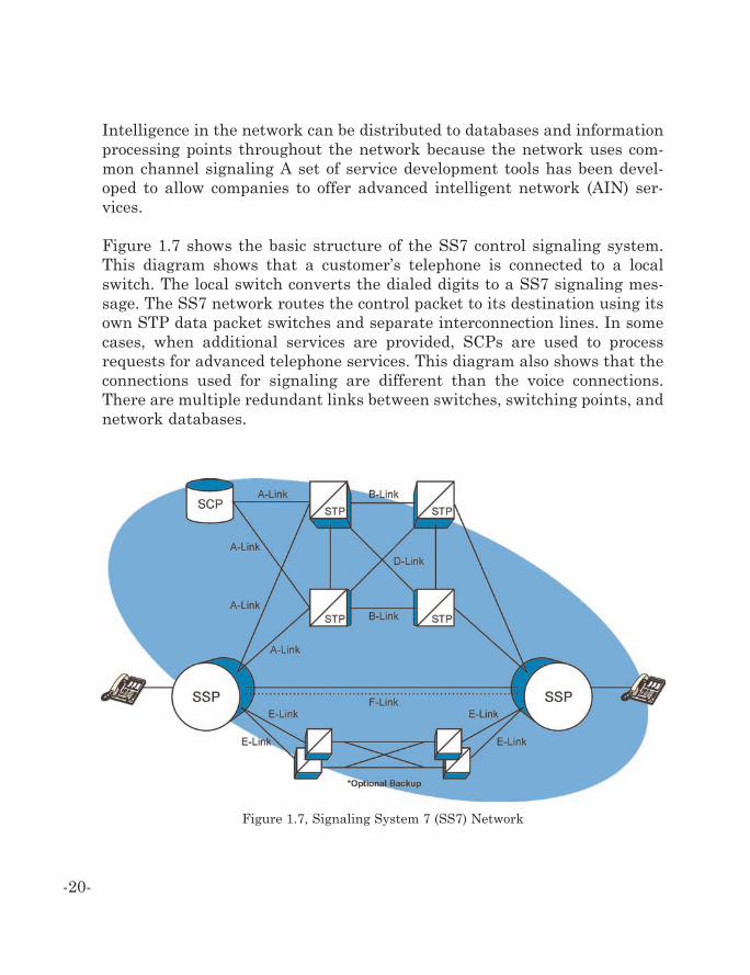
Figure 1.7 shows the basic structure of the SS7 control signaling system.This diagram shows that a customer’s telephone is connected to a localswitch. The local switch converts the dialed digits to a SS7 signaling mes-sage. The SS7 network routes the control packet to its destination using itsown STP data packet switches and separate interconnection lines. In somecases, when additional services are provided, SCPs are used to processrequests for advanced telephone services. This diagram also shows that theconnections used for signaling are different than the voice connections.There are multiple redundant links between switches, switching points, andnetwork databases.
-20-
Figure 1.7, Signaling System 7 (SS7) Network
SS7 and Internet Protocol (IP) Signaling Systems
SS7 messages can be directly transported over IP networks or the function-al equivalent of SS7 control message can be sent as control messages (e.g.text based messages) directly between elements connected to a data network(e.g. the Internet).
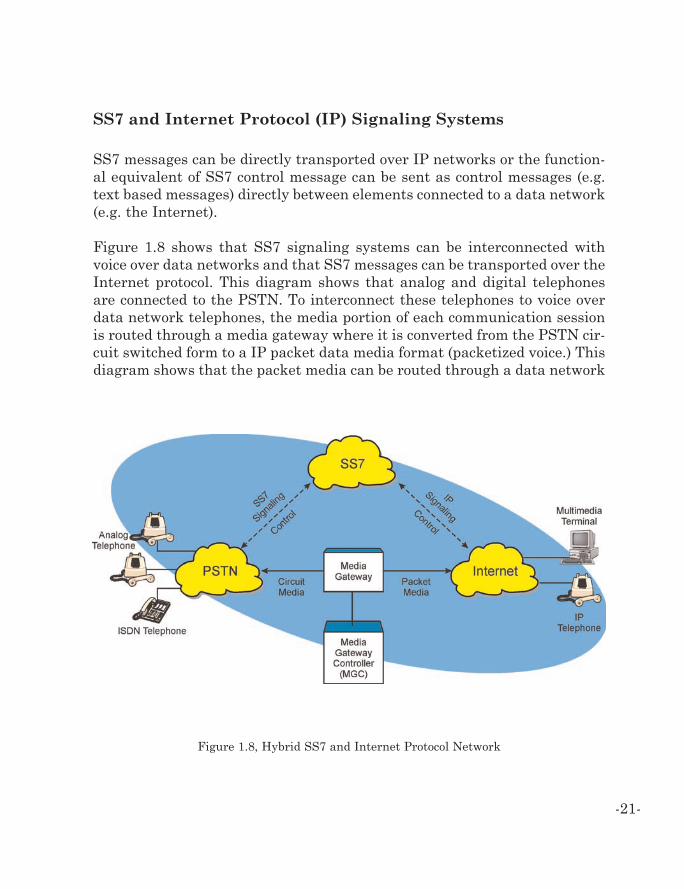
Figure 1.8 shows that SS7 signaling systems can be interconnected withvoice over data networks and that SS7 messages can be transported over theInternet protocol. This diagram shows that analog and digital telephonesare connected to the PSTN. To interconnect these telephones to voice overdata network telephones, the media portion of each communication sessionis routed through a media gateway where it is converted from the PSTN cir-cuit switched form to a IP packet data media format (packetized voice.) Thisdiagram shows that the packet media can be routed through a data network
-21-
Figure 1.8, Hybrid SS7 and Internet Protocol Network
(e.g. Internet) to an endpoint communication terminal such as a multimediacomputer or an IP telephone. This diagram also shows that the SS7 networkcan control the PSTN through SS7 signaling messages and it can communi-cate to the media gateway through IP signaling messages.
Advanced Intelligent Networks (AIN)
Advanced intelligent networks (AIN’s) are telecommunications networksthat are capable of providing advanced services through the use of distrib-uted databases that provide additional information to call processing androuting requests.
In the mid 1980’s, Bellcore (now Telcordia) developed a set of software devel-opment tools to allow companies to develop advanced services for the tele-phone network [5]. The advanced intelligent network (AIN) is a combinationof the SS7 signaling network, interactive database nodes, and developmenttools that allow for the processing of signaling messages to provided foradvanced telecommunications services.
The AIN system uses a service creation environment (SCE) to createadvanced applications. The SCE is a development tool kit that allows thecreation of services for an AIN that is used as part of the SS7 network.Using AIN, SS7 control messages can interact with signaling end point(SEP) databases that are connected to SSPs.
A service management system (SMS) is the interface between applicationsand the SS7 telephone network. The SMS is a computer system that admin-isters service between service developers and signal control point databasesin the SS7 network. The SMS system supports the development of intelli-gent database services. The system contains routing instructions and othercall processing information.
To enable SCPs to become more interactive, intelligent peripherals (IPs)may be connected to them. IPs is a type of hardware device that can be pro-grammed to perform an intelligent network processing for the SCP data-
-22-
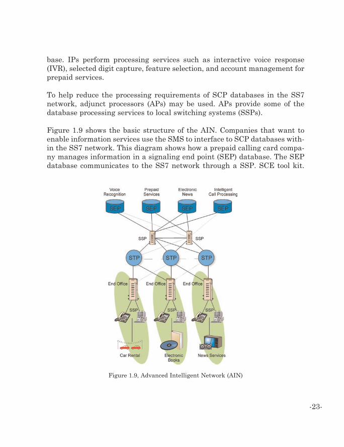
base. IPs perform processing services such as interactive voice response(IVR), selected digit capture, feature selection, and account management forprepaid services.
To help reduce the processing requirements of SCP databases in the SS7network, adjunct processors (APs) may be used. APs provide some of thedatabase processing services to local switching systems (SSPs).
Figure 1.9 shows the basic structure of the AIN. Companies that want toenable information services use the SMS to interface to SCP databases with-in the SS7 network. This diagram shows how a prepaid calling card compa-ny manages information in a signaling end point (SEP) database. The SEPdatabase communicates to the SS7 network through a SSP. SCE tool kit.
-23-
Figure 1.9, Advanced Intelligent Network (AIN)
The SEP is connected to an interactive voice response (IVR) unit thatprompts callers to enter the personal identification number (PIN). The IPthen reviews the account and determines available credit remains andinforms the SS7 network of the destination number for call routing.
Systems
Some of the key systems used in public telephone networks are POTS,ISDN, DLC, APON, and DSL. POTS systems provide basic telephone service(dialtone). ISDN provides for multi-channel digital telephone service. DLCis a concentration system that is used to extend the switching function of theEO to be closer to the end customers. APON is an efficient high-speed datacommunication system that provides data transfer through the use of fiberlines. DSL service provides high-speed data transmission through the use ofstandard copper wire pairs.
Plain Old Telephone Service (POTS)
Basic telephone service without any enhanced features. It is the commonterm for residential telephone service. The POTS system uses in-band sig-naling tones and currents to determine call status (e.g., call request).Because POTs allows for transfers of audio signals below 8 kilohertz, thedigital switching equipment does not allow digitalization of a voice callabove 8 kilohertz and therefore restricts the bandwidth that is available ondialed up calls. For this reason POTs systems can accommodate data speedsup to 56 kilobits of data transmission and is the limitation for dial-upmodem calls on the network.
-24-
Integrated Digital Services Network (ISDN)
A structured all digital telephone network system that was developed toreplace (upgrade) existing analog telephone networks. The ISDN networksupports for advanced telecommunications services and defined universalstandard interfaces that are used in wireless and wired communicationssystems.
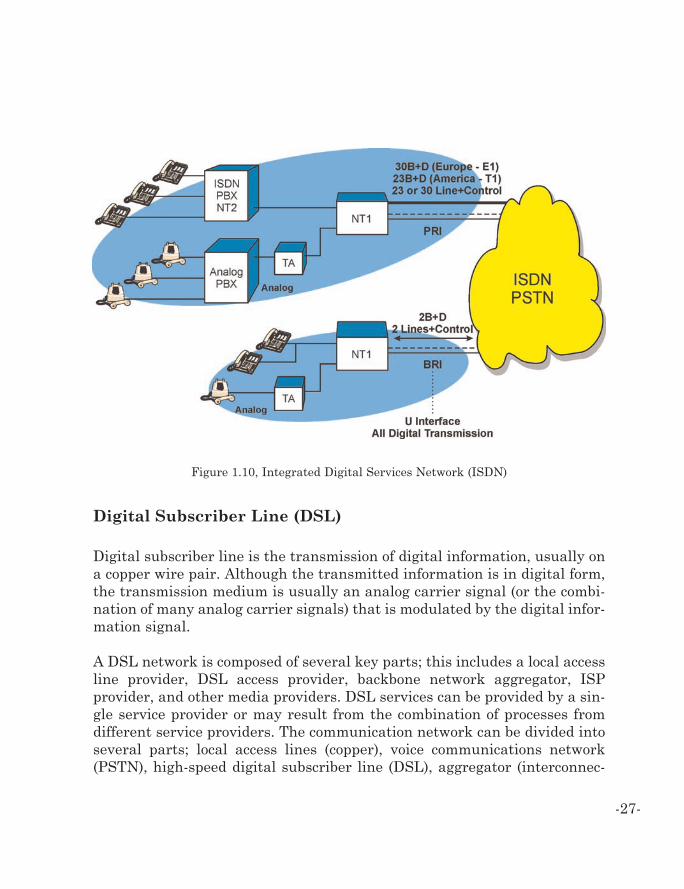
ISDN provides several communication channels to customers via local looplines through a standardized digital transmission line. ISDN is provided intwo interface formats: a basic rate (primarily for consumers) and high-speedrate (primarily for businesses). The basic rate interface (BRI) is 144 kbpsand is divided into three digital channels called 2B + D. The primary rateinterface (PRI) is 1.54 Mbps and is divided into 23B + D. The digital chan-nels for the BRI are carried over a single, unshielded, twisted pair, copperwire and the PRI is normally carried on (2) twisted pairs of copper wire. Theprimary rate also allows for the situation where there are multiple PRIs ter-minated at a particular customer for a facility that is known as non-facilityassociate signaling so that in the case of a customer who has 10 PRIs itwould be normal to expect that 10 DS0s would be dedicated for signalingother than the 10 PRIs. With non-facility associated signaling, signalingchannels of 1PR can accommodate the signaling requirements for the otherassociated PRI trunk route that’s serving that customer so the minimumnumber of signaling channels that are required for those 10 PRIs would be2. The reason there would be 2 at a minimum is to accommodate redundan-cy in the event that one signaling channel faltered for that trunk group.
The “B” channels operate at 64kb per second digital synchronous rate andthe “D” channel is a control channel. The D channel is used to coordinate(signal) the communication with the telephone network. When used on theBRI line, the D channel is 16kbps and when provided on the PRI channel,the D channel is 64 kbps. Because the amount of telephone system controlsignaling is relatively small, the D channel can also be used for low speedpacket data messaging. The 64 kbps “B” channels can be used for voice anddata. On the BRI system, the two B channels can be combined for 128 kbpsdata connection.
-25-
ISDN telephone lines exclusively use digital transmission. This requires acustomer to replace their analog telephones with ISDN digital telephoneequipment if they upgrade to ISDN service. ISDN service is typically pro-vided using modular plugs. These plugs include a RJ45 interface (8 pin) fordata equipment (called a BRI-S/T) and the other physical connection type isa two-wire, RJ11 type standard (called the BRI-U).
The maximum distance for a BRI-S/T line is approximately 3,000 feet andthe maximum distance for the BRI-U is 18,000 feet. Beyond these distances,the service provider may install repeaters to provide service. However,repeaters are expensive to install and setup.
The ISDN BRI allows the user to change the use of the B channels whenev-er desired. For example, an ISDN user may be sending data using the twoB channels at 128 Kbps. If a voice call comes in or is initiated, the datatransmission is not interrupted; but is automatically reduced to one B chan-nel at 64 Kbps. When the voice call ends, the data transmission returns to128 Kbps on the two B channels.
Figure 1.10 provides the different interfaces that are available in the inte-grated services digital network (ISDN). The two interfaces shown are BRIand PRI. These are all digital interfaces from the PSTN to the end cus-tomers network termination. 1 (NT1) equipment devices that are ISDN com-patible can directly connect to the NT1 connection. Devices that requireother standards (such as POTS or data modems) require a terminal adapter(TA).
-26-
Digital Subscriber Line (DSL)
Digital subscriber line is the transmission of digital information, usually ona copper wire pair. Although the transmitted information is in digital form,the transmission medium is usually an analog carrier signal (or the combi-nation of many analog carrier signals) that is modulated by the digital infor-mation signal.
A DSL network is composed of several key parts; this includes a local accessline provider, DSL access provider, backbone network aggregator, ISPprovider, and other media providers. DSL services can be provided by a sin-gle service provider or may result from the combination of processes fromdifferent service providers. The communication network can be divided intoseveral parts; local access lines (copper), voice communications network(PSTN), high-speed digital subscriber line (DSL), aggregator (interconnec-
-27-
Figure 1.10, Integrated Digital Services Network (ISDN)
tion), Internet service provider (ISP) and content provider (media source).These network parts and the service providers who operate them, mustinteract to provide most DSL services.
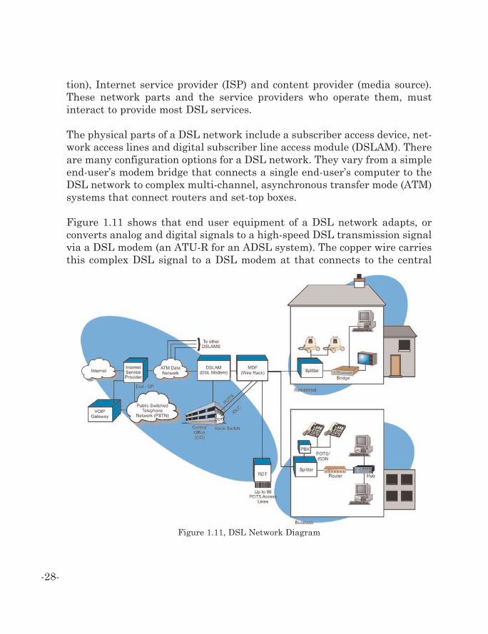
The physical parts of a DSL network include a subscriber access device, net-work access lines and digital subscriber line access module (DSLAM). Thereare many configuration options for a DSL network. They vary from a simpleend-user’s modem bridge that connects a single end-user’s computer to theDSL network to complex multi-channel, asynchronous transfer mode (ATM)systems that connect routers and set-top boxes.
Figure 1.11 shows that end user equipment of a DSL network adapts, orconverts analog and digital signals to a high-speed DSL transmission signalvia a DSL modem (an ATU-R for an ADSL system). The copper wire carriesthis complex DSL signal to a DSL modem at that connects to the central
-28-
Figure 1.11, DSL Network Diagram
office (an ATU-C for an ADSL system) where it is converted back to its ana-log and digital components. The analog telephone portion of the signal (ifany) is routed to the central office switching system. The high-speed digitalportion is routed to a digital subscriber line access multiplexer (DSLAM).The DSLAM combines (concentrates) the signals from several ATU-Cs andconverts and routes the signals to the appropriate service provider network.
Digital Loop Carrier (DLC)
Digital loop carrier (DLC) is a high efficiency digital transmission systemthat uses existing distribution cabling systems to transfer digital informa-tion between the telephone system (central office) and a telephone or othercommunication device. There are two types of DLC: universal digital loopcarrier (UDLC) and integrated digital loop carrier (IDLC).
The UDLC is a system that consists of RDTs and central office terminals(COTs). Optical systems such as synchronous optical network (SONET) cantransfer signals transparently through the COT to the RDT. The RDT pro-vides an interface between the digital transmission line (e.g., DS1) and thecustomer’s access line. The RDT can dynamically assign time slots from thecommunication line to customer access lines.
Integrated digital loop carrier (IDLC) is a digital line interface that has beenre-engineered to integrate within a switch (usually as card) and shares theinternal bus structure of the switch. This function (or card) is called an inte-grated digital terminal (IDT). Using the IDT, the switch can directly com-municate with a remote digital terminal (RDT) that is closer to the end cus-tomer using an efficient multi-channel communication line. The RDT pro-vides an interface between the high-speed digital transmission line (e.g.,DS1) and the customer’s access line. The RDT can dynamically assign timeslots from the communication line to customer access lines. Because cus-tomer access lines are not used at the same time, an RDT that interfaces toa DS1 line (24 channels) usually provides service to 96 customer accesslines.
-29-
The key advantages to DLC carrier systems are the cost effective transmis-sion and the ability to rapidly add, delete, or change customer services with-out having to dispatch an installation technician. The DLC system offersimproved efficiency through the use of existing distribution cabling systems.DLC systems also offer the ability to extend the range of access lines fromthe central office to the end customer as the RDT effectively operates as arepeater.
An RDT is divided into three major parts: digital transmission facility inter-face, common system interface, and line interface. The digital transmissioninterface terminates the high-speed line and coordinates the signaling. Thecommon system interface performs the multiplexing/de-multiplexing, sig-naling, insertion, and extraction. The line interface contains digital to ana-log conversions (if the access line is analog) or digital formatting (if the lineis digital).
DLC initially allowed 40 analog telephone connections to be extended to theremote neighborhoods using a device called an SLC-40. Later an SLC-96(known as a “slick 96”) was put into service that allowed 96 voice grade ana-log circuits to be extended from the CO on just ten (10) pairs thus reclaim-ing 86 pairs per installation. Still in use the SLC-96 has allowed the LEC’sto conserve much of their installed outside copper infrastructure.
Unfortunately, DLC systems are not transparent to other systems such asDSL systems. Although it is possible to install digital subscriber line net-work equipment (co-locate) along with RDT equipment, the RDT equipmenthousings and power supplies were not originally designed to hold addition-al equipment.
-30-
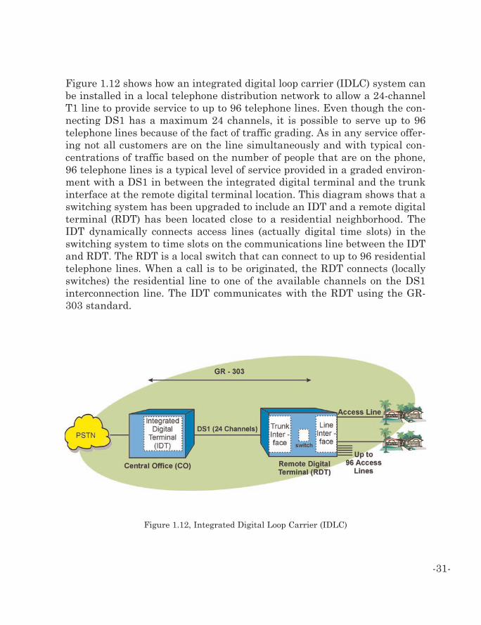
Figure 1.12 shows how an integrated digital loop carrier (IDLC) system canbe installed in a local telephone distribution network to allow a 24-channelT1 line to provide service to up to 96 telephone lines. Even though the con-necting DS1 has a maximum 24 channels, it is possible to serve up to 96telephone lines because of the fact of traffic grading. As in any service offer-ing not all customers are on the line simultaneously and with typical con-centrations of traffic based on the number of people that are on the phone,96 telephone lines is a typical level of service provided in a graded environ-ment with a DS1 in between the integrated digital terminal and the trunkinterface at the remote digital terminal location. This diagram shows that aswitching system has been upgraded to include an IDT and a remote digitalterminal (RDT) has been located close to a residential neighborhood. TheIDT dynamically connects access lines (actually digital time slots) in theswitching system to time slots on the communications line between the IDTand RDT. The RDT is a local switch that can connect to up to 96 residentialtelephone lines. When a call is to be originated, the RDT connects (locallyswitches) the residential line to one of the available channels on the DS1interconnection line. The IDT communicates with the RDT using the GR-303 standard.
-31-
Figure 1.12, Integrated Digital Loop Carrier (IDLC)
Passive Optical Network (PON)
A passive optical network (PON) combines, routes, and separates opticalsignals through the use of passive optical filters that separate and combinechannels of different optical wavelengths (different colors). The PON dis-tributes and routes signals without the need to convert them to electricalsignals for routing through switches.
PON networks are constructed of optical line termination (OLT), opticalsplitters and optical network units (ONUs). OLTs interface the telephonenetwork to allow multiple channels to be combined to different optical wave-lengths for distribution through the PON. Optical splitters are passivedevices that redirect optical signals to different locations. ONU’s terminateor sample optical signals so they can be converted to electrical signals in aformat suitable for distribution to a customer’s equipment. When used forresidential use, a single ONU can server 128 to 500 dwellings. In 2001, mostPON’s used ATM cell architecture for their transport between the providerEO or point of presence (POP) and the ONU (in some case even to the userworkstation). When ATM protocol is combined with PON system, it is calledATM passive optical network (APON).
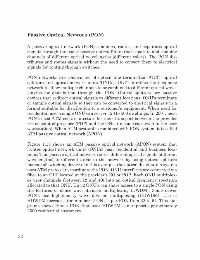
Figure 1.13 shows an ATM passive optical network (APON) system thatlocates optical network units (ONUs) near residential and business loca-tions. This passive optical network routes different optical signals (differentwavelengths) to different areas in the network by using optical splittersinstead of switching devices. In this example, the optical distribution systemuses ATM protocol to coordinate the PON. ONU interfaces are connected viafiber to an OLT located at the provider’s EO or POP. Each ONU multiplex-es user channels (between 12 and 40) into an optical frequency spectrumallocated to that ONU. Up 32 ONU’s can share access to a single PON usingthe features of dense wave division multiplexing (DWDM). Some newerPON’s use high-density wave division multiplexing (HDWDM). Use ofHDWDM increases the number of ONU’s per PON from 32 to 64. This dia-grams shows that a PON that uses HDWDM can support approximately2500 residential customers.
-32-
Services
The key services provided in public switched telephone networks includevoice (audio bandpass), Centrex, switched data communications service,leased line, and digital subscriber line.
Voice
Voice service is the providing of audio communication circuits that can passanalog frequencies below 3.3 kHz. Voice service is commonly called plain oldtelephone service (POTS).
-33-
Figure 1.13, Passive Optical Network (PON)
The newer EO switches have enhanced voice services to allow residentialcustomers to have practically all the features normally associated withPBX’s that serve businesses such as: call waiting, distinctive ringing, voicemail (with signaling or stutter dial tone), feature telephones, and incomingWATS. Some of the newer features are packaged (bundled) together so theiractual cost is not readily known.
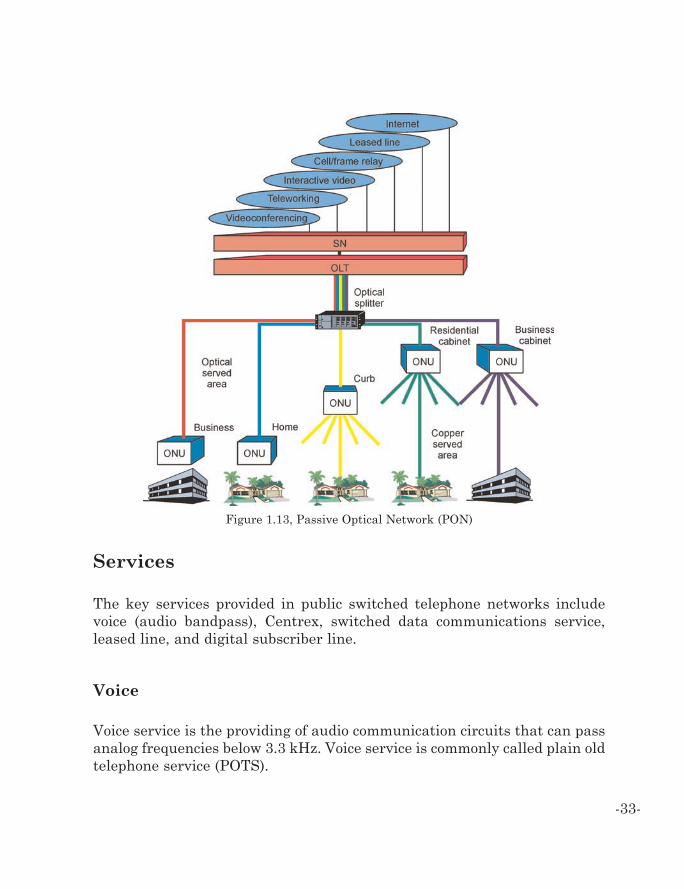
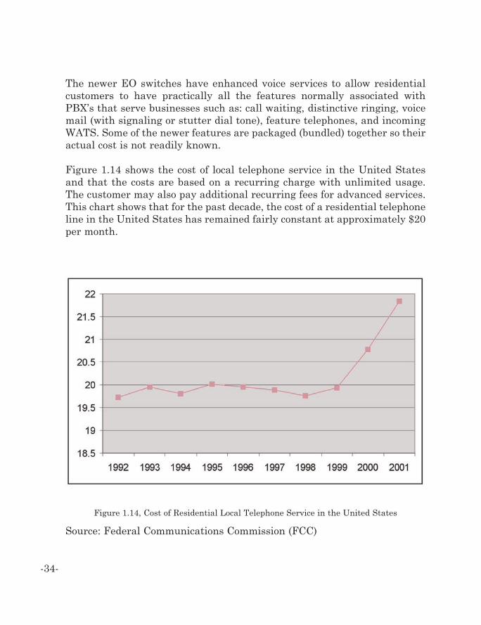
Figure 1.14 shows the cost of local telephone service in the United Statesand that the costs are based on a recurring charge with unlimited usage.The customer may also pay additional recurring fees for advanced services.This chart shows that for the past decade, the cost of a residential telephoneline in the United States has remained fairly constant at approximately $20per month.
-34-
Figure 1.14, Cost of Residential Local Telephone Service in the United States
Source: Federal Communications Commission (FCC)
Outside the United States, the cost structure for local telephone service isoften based on actual usage with charges for each minute used ranging from2 to 6 cents per minute.
Centrex
Centrex is a service offered by a local telephone service provider (primarilyto businesses) that allows the customer to have features that are typicallyassociated with a PBX. These features include 3 or 4 digit dialing, intercomfeatures, distinctive line ringing for inside and outside lines, voice mail, callwaiting indication, and others.
Centrex services have had many names over the years, but, whatever thename, the purpose of this offering was always the same: an alternative tocustomer premises PBX’s. Centrex services flourished and still have a placefor many large, dispersed entities such as large universities and major med-ical centers.
One of the major selling points for Centrex is the lack of capital expenditureup front. That coupled with the reliability associated with Centrex due to itslocation in the telephone company CO have kept Centrex as the primarytelephone system in many of the businesses referenced above. PBX’s, how-ever, have cut into what was once a quite lucrative market for the telephonecompanies and are now the rule rather than the exception for business tele-phone service. This has come about because of inventive ways of funding theinitial capital outlay and the significantly lower operating cost of a PBX ver-sus a comparable Centrex offering.
Frame Relay Service
Frame relay is a packet-switching technology that provides dynamic band-width assignments. Frame relay systems are a simple bearer (transportonly) technology and do not offer advanced error protection or retransmis-sion. Frame relay were developed in the 1980s as a result of improved digi-
-35-
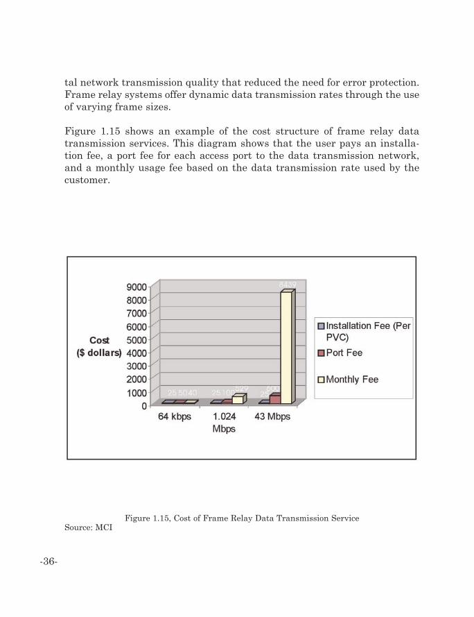
tal network transmission quality that reduced the need for error protection.Frame relay systems offer dynamic data transmission rates through the useof varying frame sizes.
Figure 1.15 shows an example of the cost structure of frame relay datatransmission services. This diagram shows that the user pays an installa-tion fee, a port fee for each access port to the data transmission network,and a monthly usage fee based on the data transmission rate used by thecustomer.
-36-
Figure 1.15, Cost of Frame Relay Data Transmission ServiceSource: MCI
Leased Lines
Leased lines are telecommunications circuits (either two-wire or four-wire)rented/leased from a telephone company to connect two or more locations ona permanent basis. Leased lines are normally associated with data servicesor voice PBX tie line services. Leased lines are ordered as either analog ordigital circuits. Analog circuits provide a single full duplex (two-way) pathbetween locations. They terminate in either telephone switches/instrumentsor in modems. Digital leased lines, on the other hand, terminate in customerservice units (CSU’s) rather than modems. The cost of leased lines dependson the region of service, specific carrier pricing plan, and on distance (linelength). As a result, leased lines often connect the end user to another car-rier that interconnects another leased line to allow connection to its desti-nation. As a result, leased line prices are often quoted from the customer’slocation to an EO or POP of a carrier.
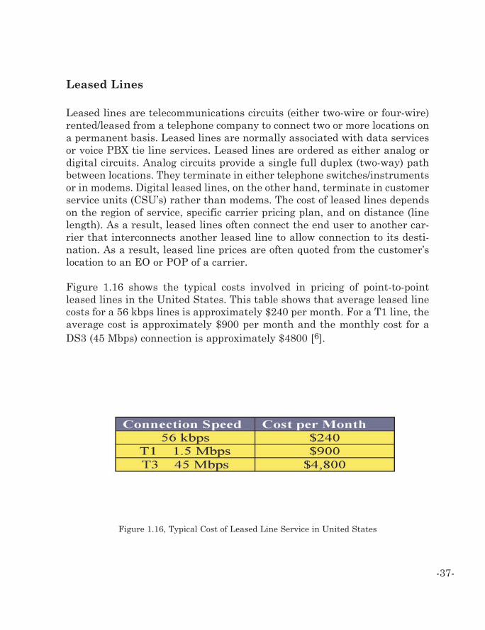
Figure 1.16 shows the typical costs involved in pricing of point-to-pointleased lines in the United States. This table shows that average leased linecosts for a 56 kbps lines is approximately $240 per month. For a T1 line, theaverage cost is approximately $900 per month and the monthly cost for aDS3 (45 Mbps) connection is approximately $4800 [6].
-37-
Figure 1.16, Typical Cost of Leased Line Service in United States
Digital Subscriber Line (DSL)
Digital subscriber line (DSL) service is a data service that offers varyingdata transmission rates to customer. DSL service usually connects usersdirectly to an Internet service provider (ISP). DSL service is generally lowerin cost than leased line cost. The difference between DSL service and leasedline service is that DSL service does not usually guarantee a data trans-mission rate.
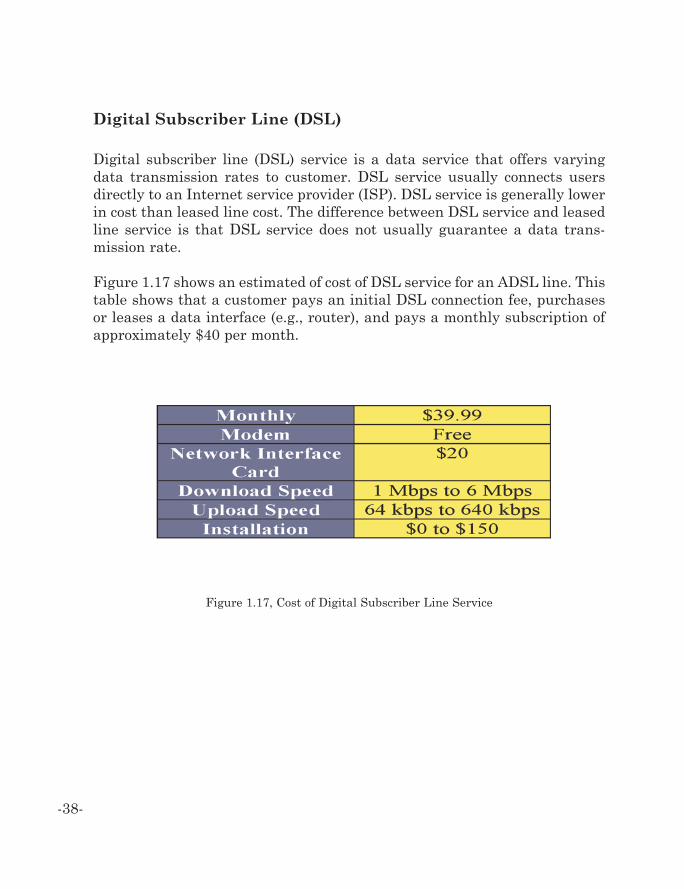
Figure 1.17 shows an estimated of cost of DSL service for an ADSL line. Thistable shows that a customer pays an initial DSL connection fee, purchasesor leases a data interface (e.g., router), and pays a monthly subscription ofapproximately $40 per month.
-38-
Figure 1.17, Cost of Digital Subscriber Line Service
Future Enhancements
The future enhancements to public switched telephone networks include theconversion from circuit switched systems to packet networks, expandedfiber networks, multimedia services, and soft switching systems.
Packetized Voice
Packetized voice is the process of converting audio signals into digital pack-et format, transferring these packets through a packet network, reassem-bling these packets into their original data form, and then recreating theaudio signals. This form of communication is commonly called IP Telephony.
By the end of 2001, over 5% of international calls from the United Stateswere over the Internet and more than 9.5% of all inter-exchange telecom-munications calls were on managed packet switching networks [7].Packetized voice transmission allows for key features such as dynamicbandwidth allocation and advanced services. To convert to packetized voice,the EO exchange is either replaced or supplemented by a packet switch.
Various protocols such as session initiation protocol (SIP), H.323, and mediagateway control protocol (MGCP) have been developed to permit telephonyservices to operate on data networks. Several services have come into exis-tence in the United States provided that a customer has his own broadbandconnection. A SIP protocol service offering allows for a digital to packet oranalog to packet converter at the customer’s location that a typical standardtelephone is attached to. This telephone service completely bypasses theincoming local exchange services in the community.
-39-
High-Speed Multimedia Services
A high-speed multimedia services is the term used to describe the deliveryof different types of information such as voice, data or video. Communicationsystems may separately or simultaneously transfer multimedia informa-tion. High-speed multimedia usually refers to image based media such aspictures, animation, or video clips. High-speed multimedia usually requirespeak data transfer rates of 1 Mbps or more.
The providing (provisioning) of multimedia services requires communicationlines that can have multiple channels and each of these channels may havedifferent quality of service (QoS) levels. As a result, many emerging multi-media services are likely to use ATM.
Fiber Distribution Networks
Fiber distribution networks use optical fiber to distribute communicationchannels from the PSTN to end customers. There are three key distributionnetworks: fiber to the neighborhood (FTTN), fiber to the curb (FTTC), andfiber to the home (FTTH).
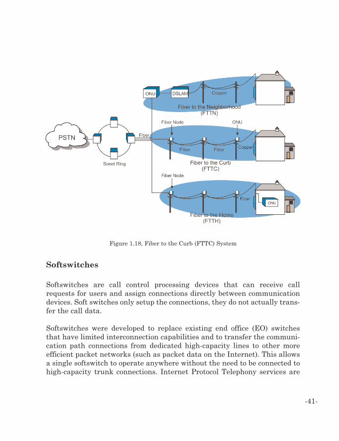
Figure 1.18 show that public telephone networks have growth options.Initially, they are likely to install (FTTN) and use existing copper lines toreach the home. As demand grows for high-speed data communication ser-vices, additional fiber may be installed from the node to the curb (FTTC) toreplace copper lines. Eventually, to achieve extremely high data rates to thehome or business, FTTH or fiber to the basement (FTTB) may be installed.
-40-
Softswitches
Softswitches are call control processing devices that can receive callrequests for users and assign connections directly between communicationdevices. Soft switches only setup the connections, they do not actually trans-fer the call data.
Softswitches were developed to replace existing end office (EO) switchesthat have limited interconnection capabilities and to transfer the communi-cation path connections from dedicated high-capacity lines to other moreefficient packet networks (such as packet data on the Internet). This allowsa single softswitch to operate anywhere without the need to be connected tohigh-capacity trunk connections. Internet Protocol Telephony services are
-41-
Figure 1.18, Fiber to the Curb (FTTC) System
provided to customers with a converting device that attaches to a broadbandconnection and plugs into a standard analog telephone at the user’s location.Gateway devices which interface the Internet Protocol system to the publicswitch telephone network are located in strategic markets around thenation such that originating calls from a given community can be done onthe IPT system as well as termination of calls anywhere to non-internet pro-tocol telephones is supported. One particular advantage of the service offer-ing is that no matter where you are located on the public internet networkyour telephone service would operate so it is quite portable and in the eventthat you want to take your analog to packet conversion box to different loca-tions on the public internet, the service will work without the originatingcaller understanding that the telephone number that he is dialing is actual-ly not located in the general service area of a particular telephone number.Based on the quality of the broadband service that the customer subscribesto, quality for these types of calls can be very good and at par with publicswitch telephone network quality and provide additional calling capabilitiesand functions greater than are available in public switch telephone networkservices.
References
1 “Main Telephone Lines,” International Telecommunications Union,www.itu.int, 24 April, 20032 “Local Telephone Competition: Status as of December 31, 2001,” FederalCommunications Commission, July 2002.3 Federal Communications Commission “Trends in Telephone Service”, December,20004 Odlyzko, Andrew, “Growth Rate of the Internet” 2001.5. Communications Systems & Networks, Ray Horak, 2000, M&T Press.
-42-
Access Provider, 27Addressing
H.323, 39SS7, 2, 15, 18-24Telephone Number, 6-8, 10, 13, 19,
42Allocating
Area codes, 6, 9Bandwidth, 24, 35, 39
Area Codes, 6, 9Assignment, 5Associated Signaling, 25B Channel, 26Backbone, 27Bandwidth
Frame Relay, 35-36Bearer, 15-16, 35Bidirectional, 7Billing, 10, 15, 17Broadband, 39, 42Call
Routing, 2, 6, 10, 16, 19, 22, 24, 32Waiting, 34-35
Call Forwarding, 13, 17, 19Call Processing, 3, 5, 10, 13, 17, 22Call Routing, 2, 24Centralized Switching, 5Centrex, 33, 35Crossbars, 5D Channel, 25Data Rate, 36, 38Dialtone, 24Dialup Connection” Dialup | Dial-up, 10, 24
Digit Capture, 23Directory Assistance, 17Distributed Switching, 5E&M Signaling, 17E.164, 8-9Frame Relay, 35-36Gateway, 21-22, 39, 42H.323, 39Interconnect, 1, 5, 7, 13, 18, 21ISDN-BRI, 15-16ISDN-PRI, 16Last mile, 3Leased Line, 33, 37-38Local Loop, 3-4, 25NNX, 6NPA, 8Number Portability, 9, 13Numbering Plan, 7-8Outside Plant, 3-4Packet Switching, 39POTS, 14, 24, 26, 33Prepaid, 13, 23Protocol
H.323, 39IP, 21-22, 24, 39SIP, 39
Provisioning, 40RJ11, 26RJ45, 26Softswitch, 41Switching, 1, 3, 5-6, 10, 13, 16, 18-20, 23-24, 29, 31-32, 39T-1” T1 | T-1, 12, 15, 31, 37Tandem, 1, 6, 17Toll free/Freephone, 10, 16
-43-
Index
Sigma Publishing
1001 Introduction to Data Networks1002 Introduction to Transmission Systems1003 Introduction to Wireless Systems1004 Introduction to Wireless Technology Basics
1101 Introduction to Private Telephone Systems1102 Introduction to Paging Systems
1201 Introduction to ATM1202 Introduction to 802.11 Wireless LAN (WLAN)1203 Introduction to Signaling System 7 (SS7)
1301 Introduction to Mobile Data1302 Introduction to Mobile Telephone Systems1303 Introduction to GSM (Global System for Mobile Communication)1304 Introduction to GPRS and EDGE1305 Introduction to Private Land Mobile Radio1306 Introduction to EVDO
1401 Introduction to Bluetooth1402 Introduction to CDMA1403 Introduction to WCDMA1404 Introduction to Digital Subscriber Line (DSL)
1501 Introduction to IP Telephony Basics1502 Introduction to IP Telephony Technology1503 Introduction to SS7 and IP1504 Introduction to SIP IP Telephony Systems1505 Introduction to IP Television
1601 Introduction to Optical Communication1602 Introduction to Satellite Systems
Sr No. Title
Computer Communication Study Guide Series Books