Embed Size (px)
Citation preview

Dr. Naveed Anwar
Modeling and Design of Bridge Super Structure and Sub Structure
Topic 3Day 2
Naveed Anwar
Dr. Naveed Anwar2
1. Over view of Bridge Design Process and Bridge Types
2. Advances and recent trends in Modeling and Analysis of Bridges
3. Design of Bridge Super Structure and Sub Structure
4. International Bridge Design Standards and Approaches
Dr. Naveed Anwar3
Why do we want to treat Sub Structure Separately ?
(for analysis purposes)
Dr. Naveed Anwar4
Dr. Naveed Anwar5
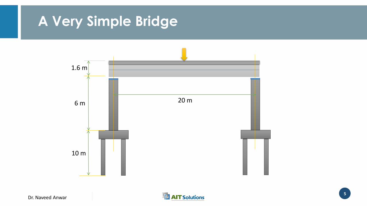
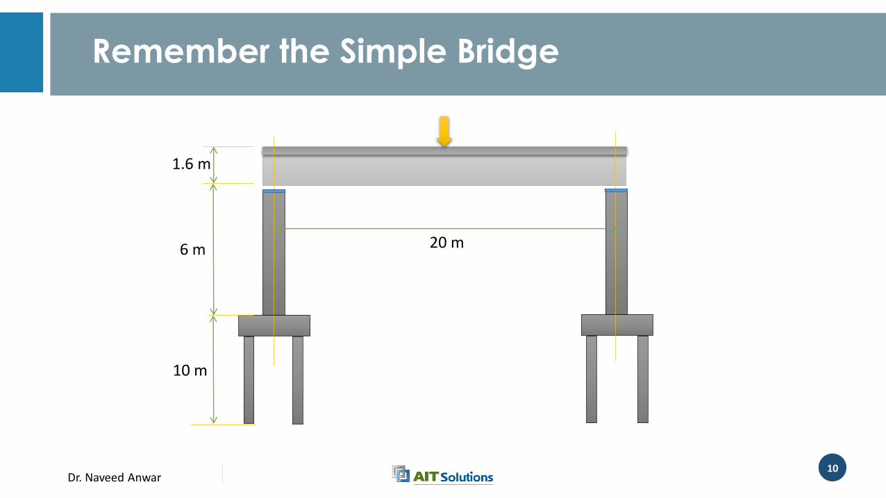
20 m
1.6 m
6 m
10 m
A Very Simple Bridge
Dr. Naveed Anwar6
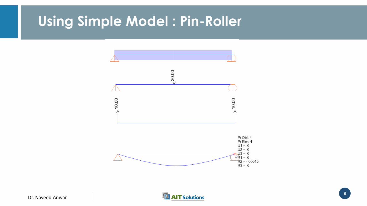
Using Simple Model : Pin-Roller
Dr. Naveed Anwar7
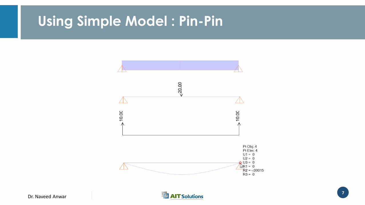
Using Simple Model : Pin-Pin
Dr. Naveed Anwar8
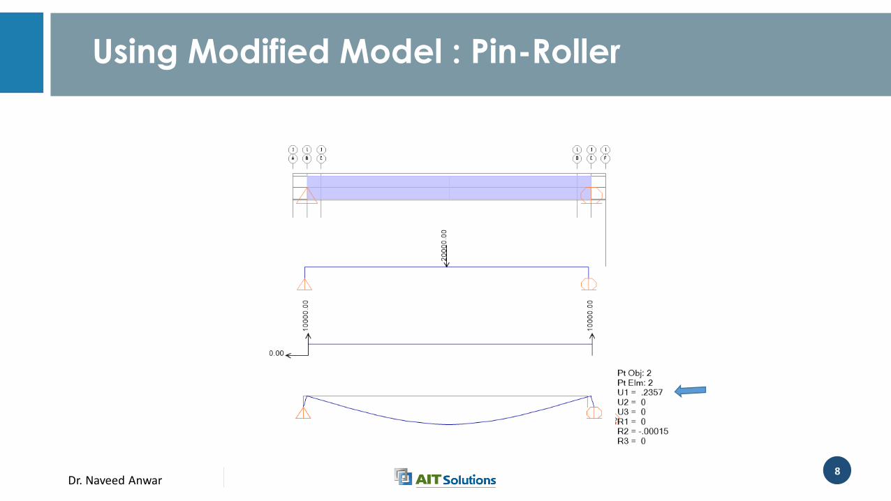
Using Modified Model : Pin-Roller
Dr. Naveed Anwar9
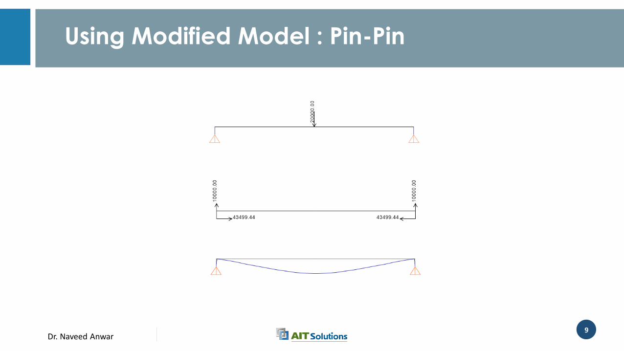
Using Modified Model : Pin-Pin
Dr. Naveed Anwar10
20 m
1.6 m
6 m
10 m
Remember the Simple Bridge
Dr. Naveed Anwar11
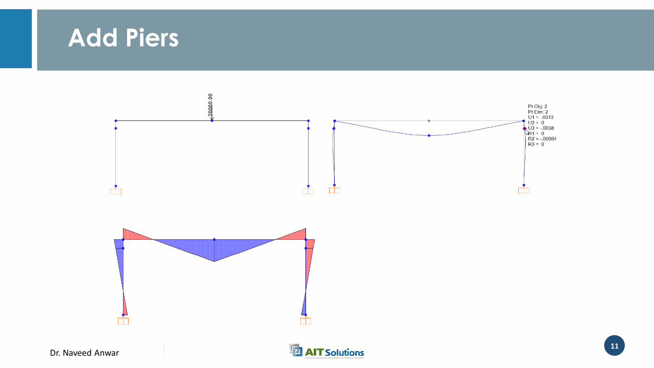
Add Piers
Dr. Naveed Anwar12
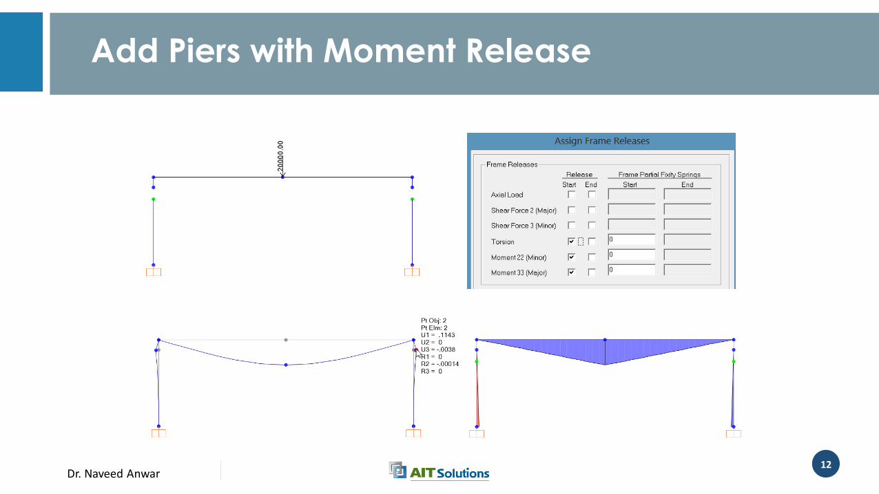
Add Piers with Moment Release
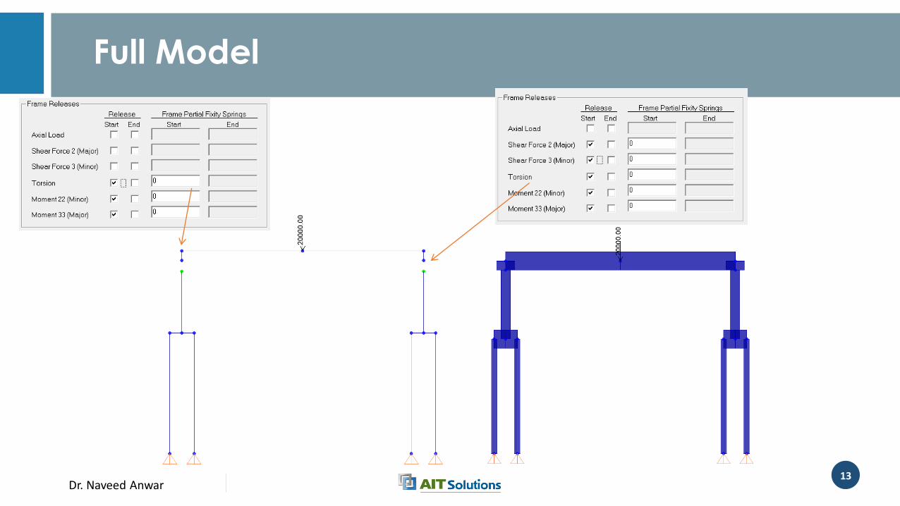
Dr. Naveed Anwar13
Full Model
Dr. Naveed Anwar14
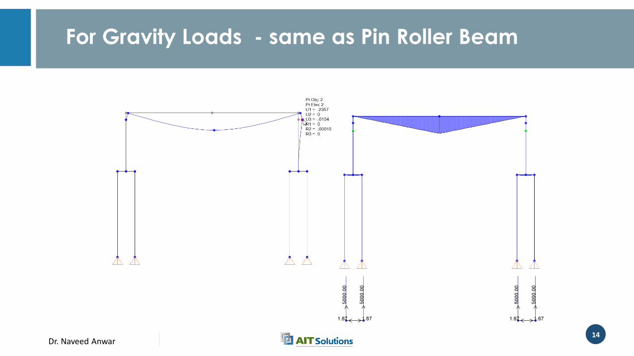
For Gravity Loads - same as Pin Roller Beam
Dr. Naveed Anwar15
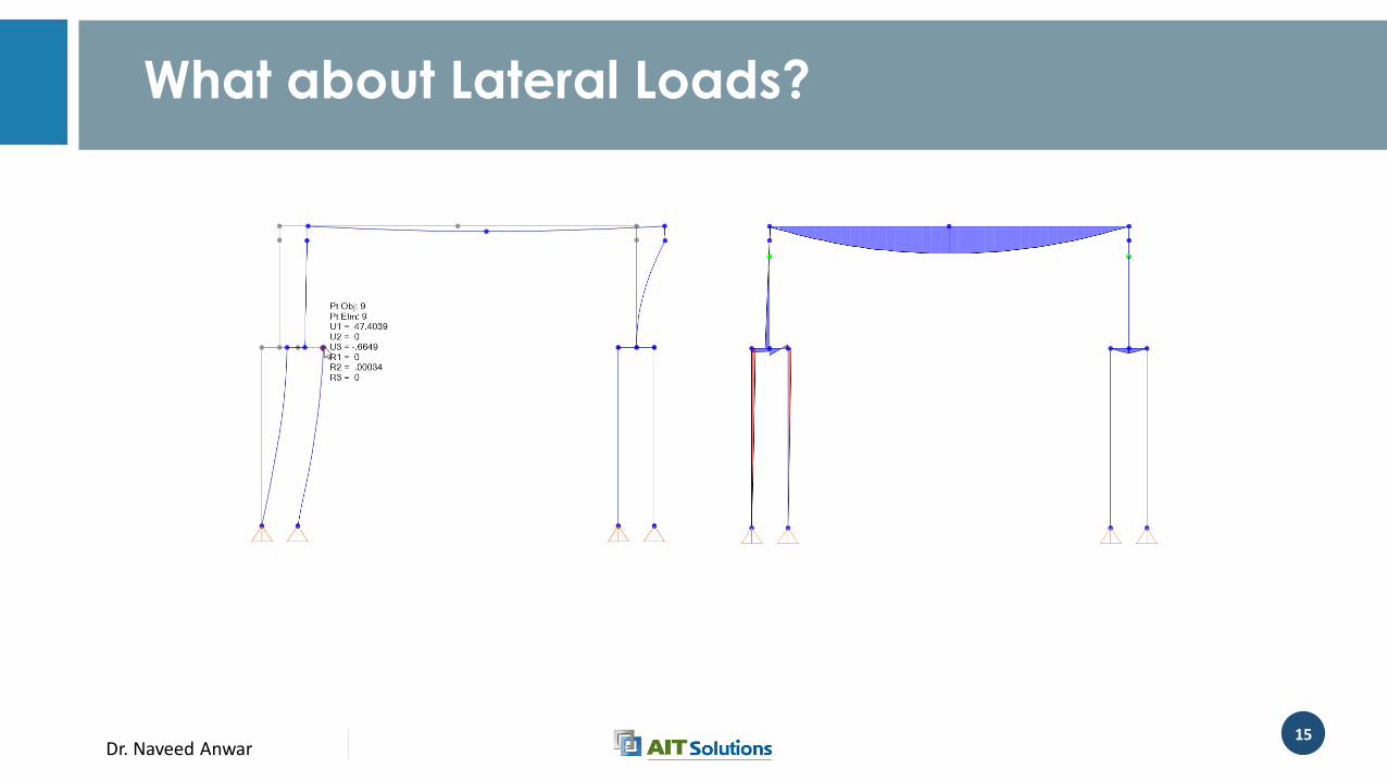
What about Lateral Loads?
Dr. Naveed Anwar16
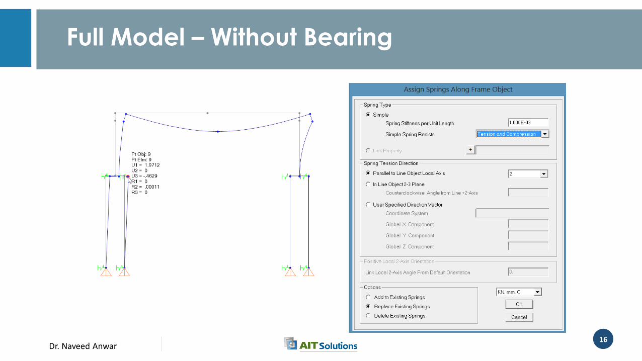
Full Model – Without Bearing
Dr. Naveed Anwar17
What can we note
• It is possible, and preferable to model and analyze the super and sub-structure together
• We need to take care of:• Connection between deck and sub-structure parts
• Connection between piers and footings
• Interaction between footing, piles and soil
• Specially, complex behavior of Abutments.
• Key issues• Bearing modeling
• Soil modeling
• Boundary conditions
Dr. Naveed Anwar18
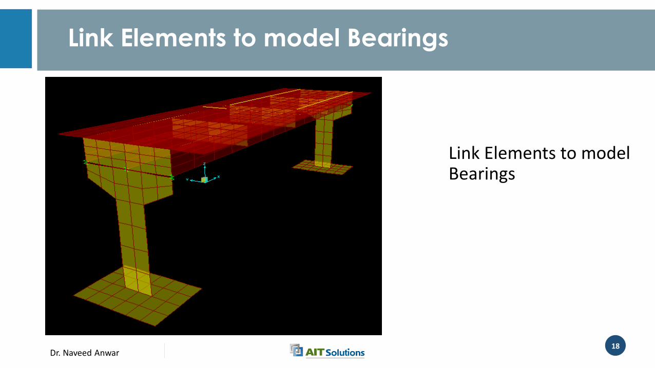
Link Elements to model Bearings
Link Elements to model Bearings
Dr. Naveed Anwar19
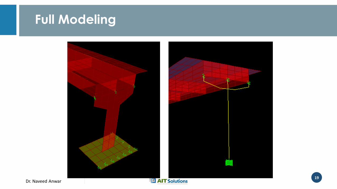
Full Modeling
Dr. Naveed Anwar20
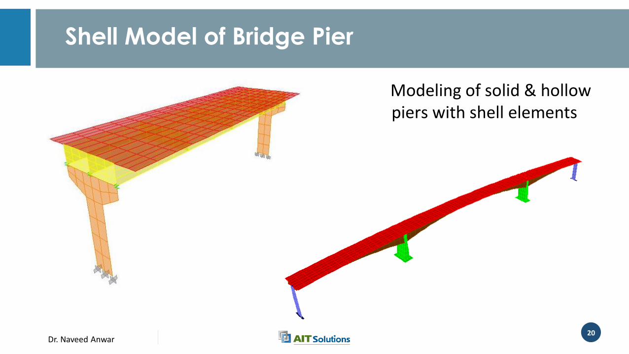
Shell Model of Bridge Pier
Modeling of solid & hollow piers with shell elements
Dr. Naveed Anwar21
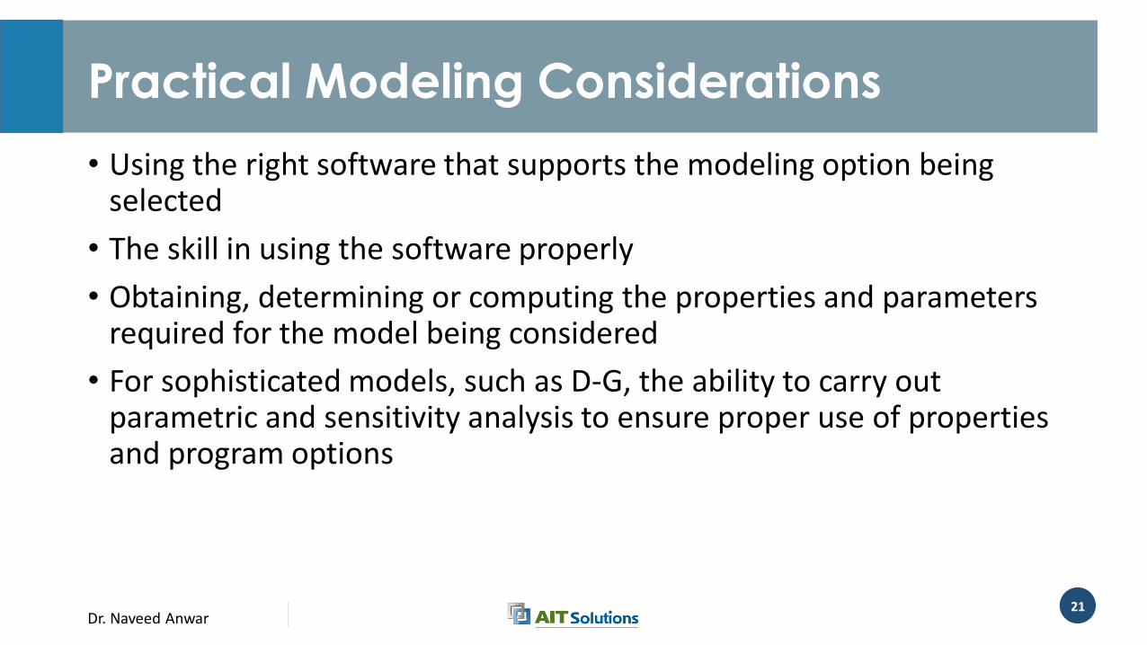
Practical Modeling Considerations
• Using the right software that supports the modeling option being selected
• The skill in using the software properly
• Obtaining, determining or computing the properties and parameters required for the model being considered
• For sophisticated models, such as D-G, the ability to carry out parametric and sensitivity analysis to ensure proper use of properties and program options
Dr. Naveed Anwar22
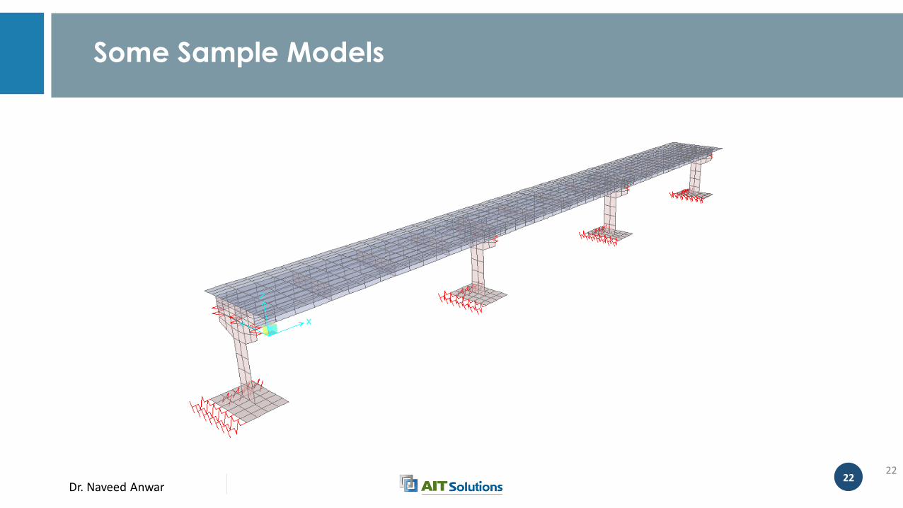
Some Sample Models
22
Dr. Naveed Anwar23
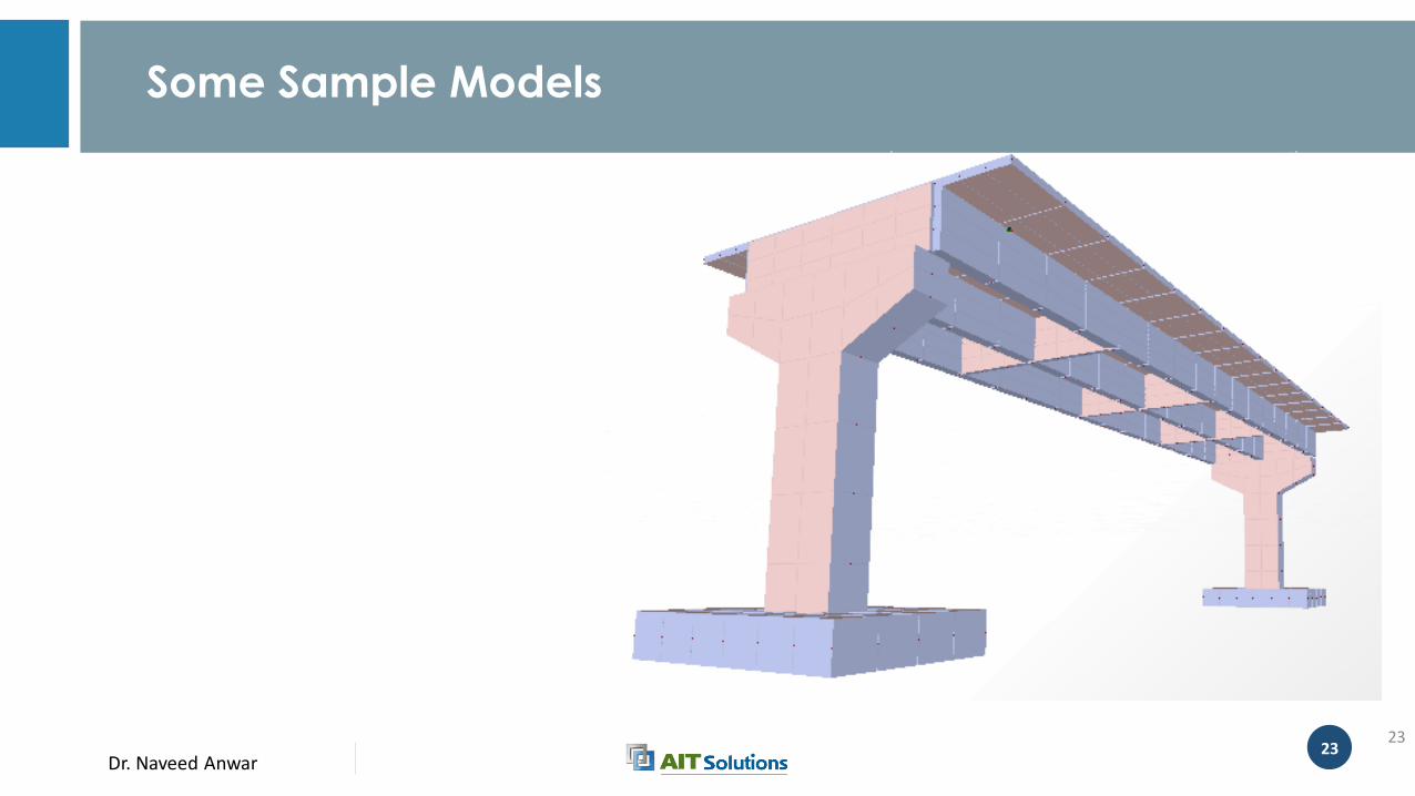
Some Sample Models
23
Dr. Naveed Anwar24
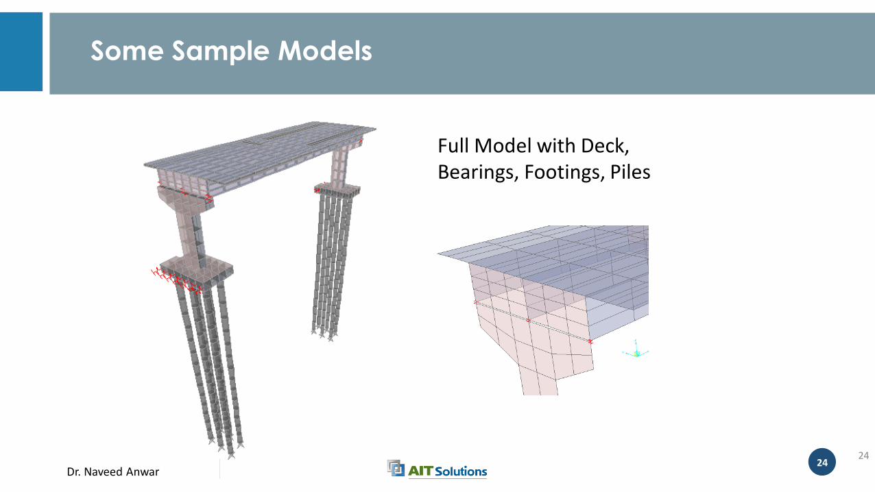
Some Sample Models
24
Full Model with Deck, Bearings, Footings, Piles

Dr. Naveed Anwar
Modeling of Deck
Dr. Naveed Anwar26
Modeling of the Bridge Deck
• Beam Model
• Grid Model
• Grid-Plate Model
• Thin Wall model
• Plate-Shell Model
• Solid Model
Dr. Naveed Anwar27
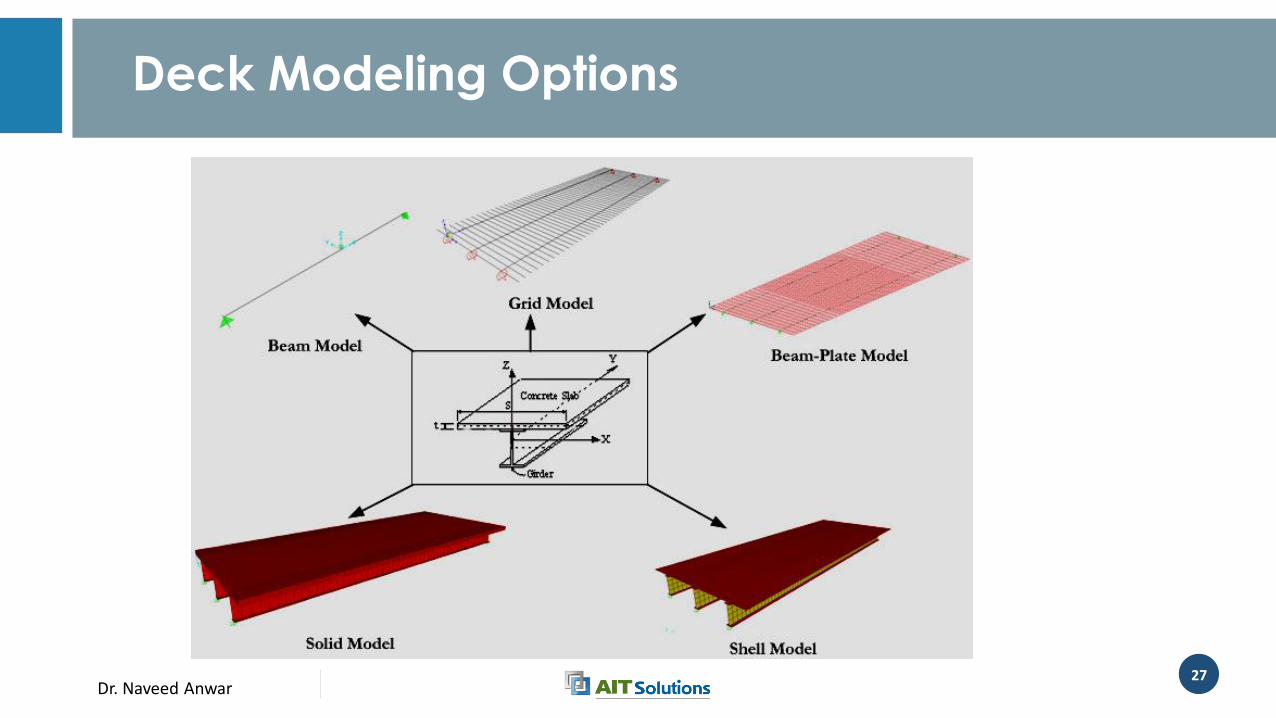
Deck Modeling Options
Dr. Naveed Anwar28
Beam Model
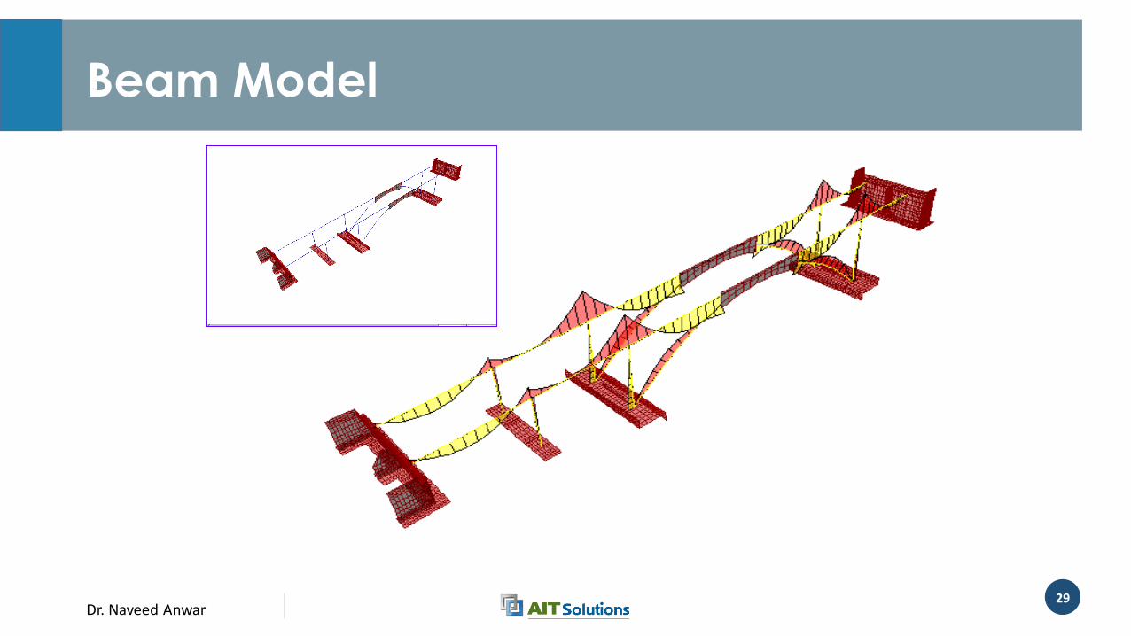
• Simple Beam Model• Only the CL of the Deck is modeled by Equivalent beam elements
• Full Beam Model• Every bridge component is modeled by beam elements
Dr. Naveed Anwar29
Beam Model
Dr. Naveed Anwar30
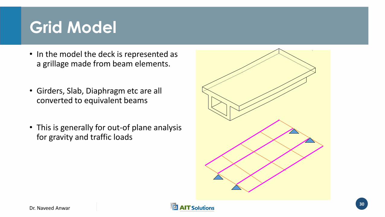
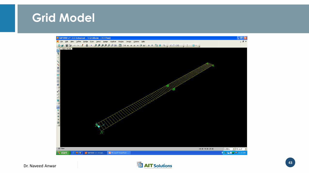
Grid Model
• In the model the deck is represented as a grillage made from beam elements.
• Girders, Slab, Diaphragm etc are all converted to equivalent beams
• This is generally for out-of plane analysis for gravity and traffic loads
Dr. Naveed Anwar31
Grid Model
• Most suitable for I beam or T beam deck with diaphragms
• Suitable for transverse distribution of traffic load
• Generally made for one or two spans for local analysis
• Slab can be represented by equivalent beam strips
• Can be in 2D or in 3D
• Can be combined with the full Beam Model
Dr. Naveed Anwar32
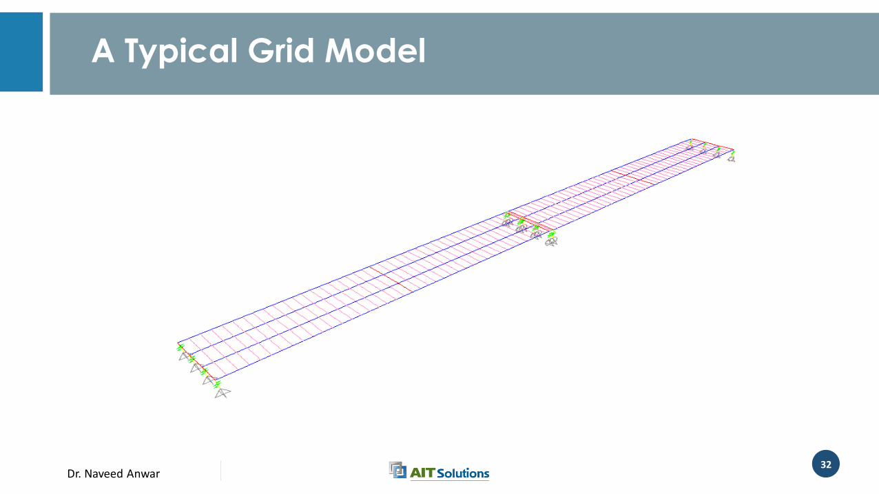
A Typical Grid Model
Dr. Naveed Anwar33
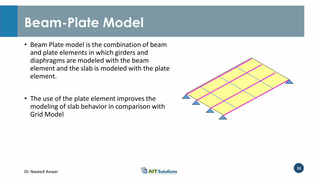
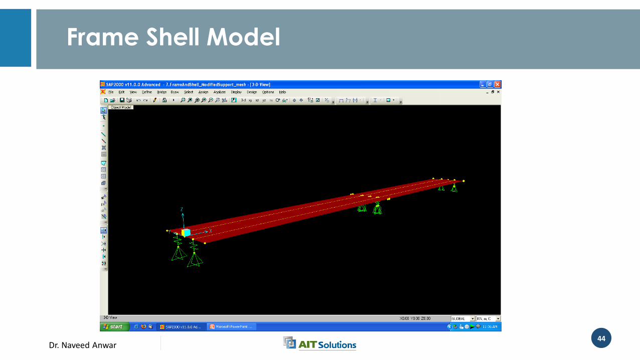
Beam-Plate Model
• Beam Plate model is the combination of beam and plate elements in which girders and diaphragms are modeled with the beam element and the slab is modeled with the plate element.
• The use of the plate element improves the modeling of slab behavior in comparison with Grid Model
Dr. Naveed Anwar34
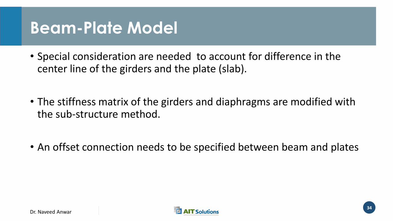
Beam-Plate Model
• Special consideration are needed to account for difference in the center line of the girders and the plate (slab).
• The stiffness matrix of the girders and diaphragms are modified with the sub-structure method.
• An offset connection needs to be specified between beam and plates

Dr. Naveed Anwar35
Beam-Plate Model
h +
Dr. Naveed Anwar36
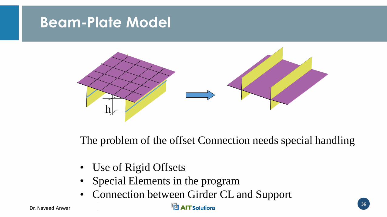
Beam-Plate Model
h
The problem of the offset Connection needs special handling
• Use of Rigid Offsets
• Special Elements in the program
• Connection between Girder CL and Support
Dr. Naveed Anwar37
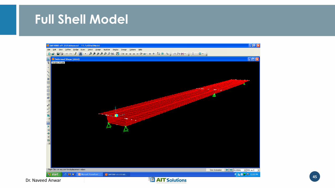
Shell Model
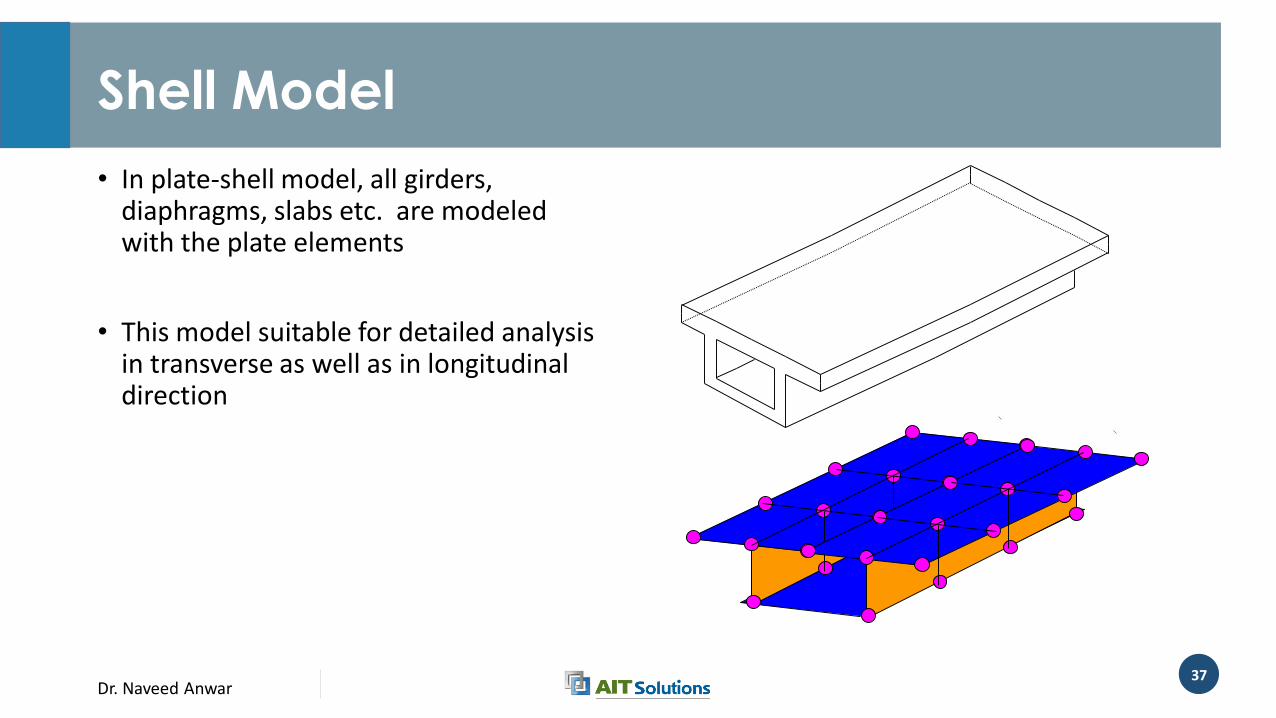
• In plate-shell model, all girders, diaphragms, slabs etc. are modeled with the plate elements
• This model suitable for detailed analysis in transverse as well as in longitudinal direction
Dr. Naveed Anwar38
Plate - Shell Model
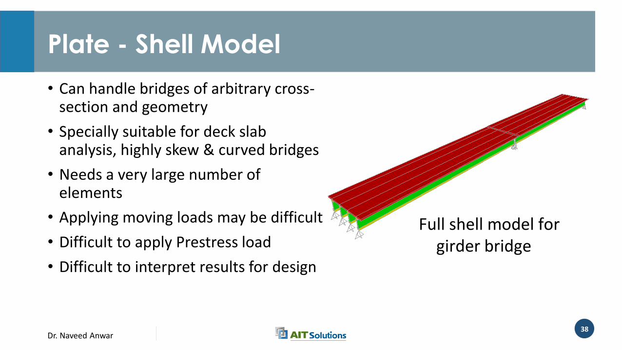
• Can handle bridges of arbitrary cross-section and geometry
• Specially suitable for deck slab analysis, highly skew & curved bridges
• Needs a very large number of elements
• Applying moving loads may be difficult
• Difficult to apply Prestress load
• Difficult to interpret results for design
Full shell model for girder bridge
Dr. Naveed Anwar39
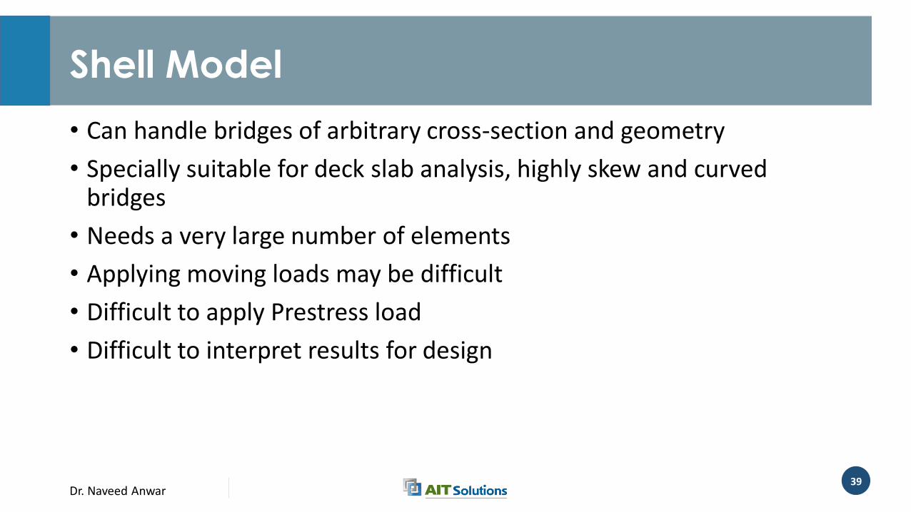
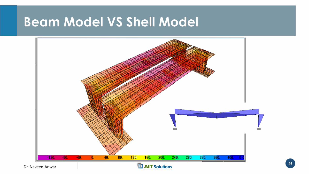
Shell Model
• Can handle bridges of arbitrary cross-section and geometry
• Specially suitable for deck slab analysis, highly skew and curved bridges
• Needs a very large number of elements
• Applying moving loads may be difficult
• Difficult to apply Prestress load
• Difficult to interpret results for design
Dr. Naveed Anwar40
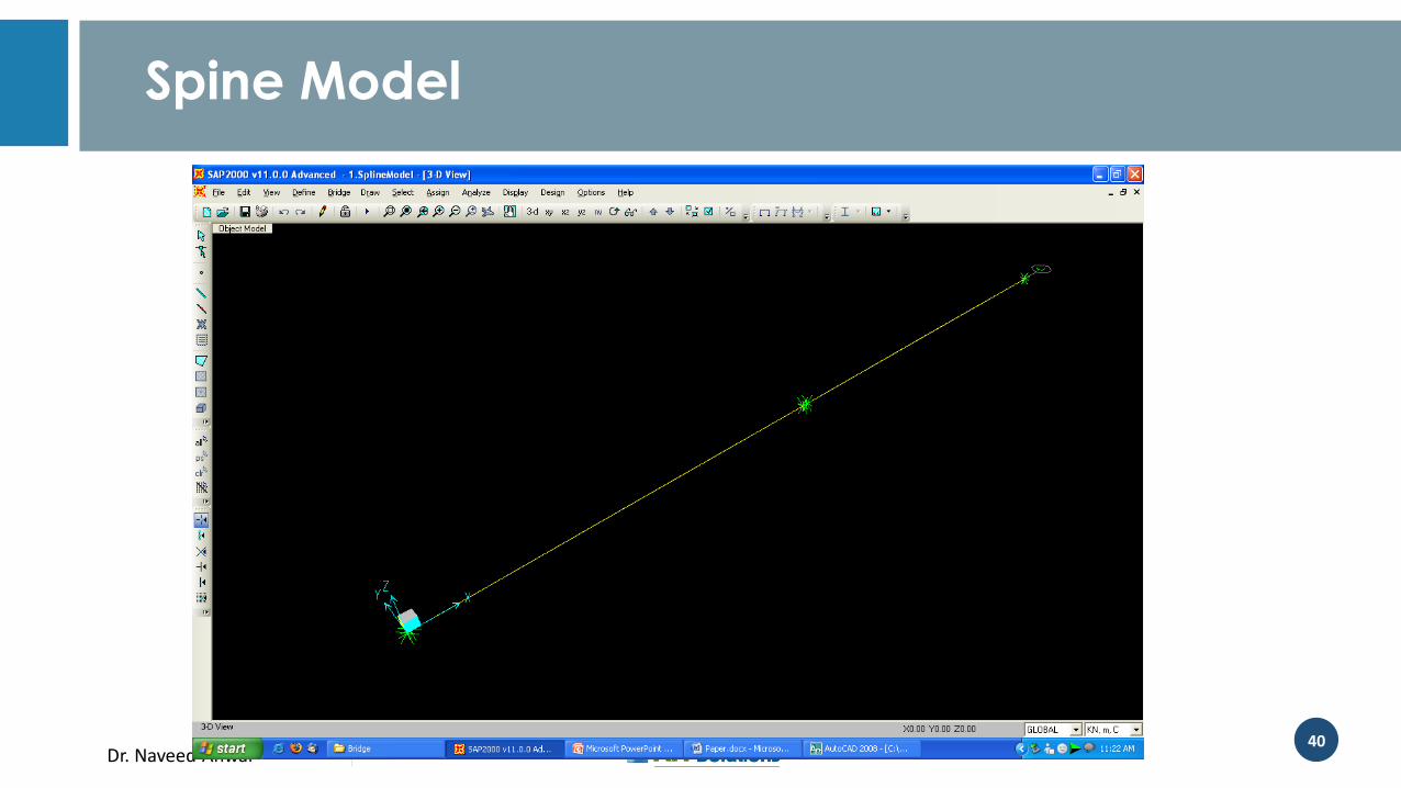
Spine Model
Dr. Naveed Anwar41
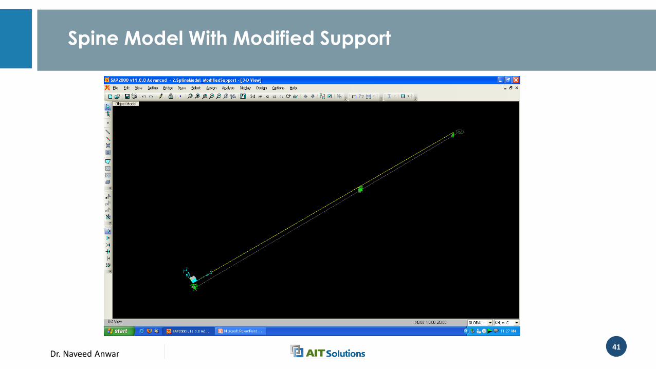
Spine Model With Modified Support
Dr. Naveed Anwar42
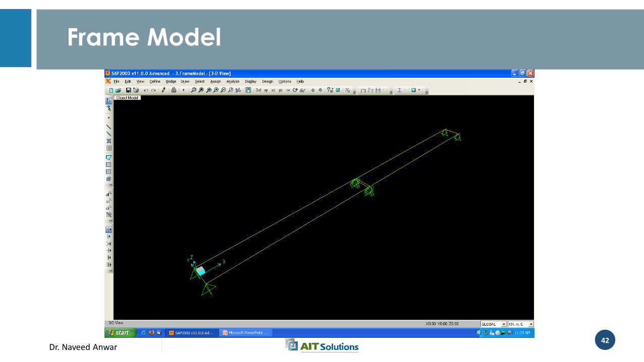
Frame Model
Dr. Naveed Anwar43
Grid Model
Dr. Naveed Anwar44
Frame Shell Model
Dr. Naveed Anwar45
Full Shell Model
Dr. Naveed Anwar46
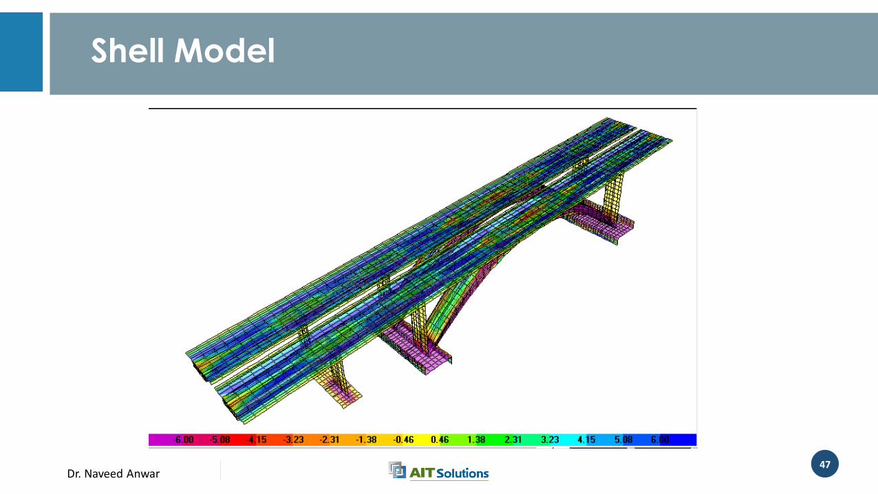
Beam Model VS Shell Model
Dr. Naveed Anwar47
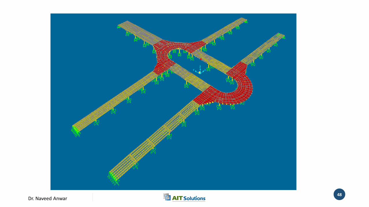
Shell Model
Dr. Naveed Anwar48
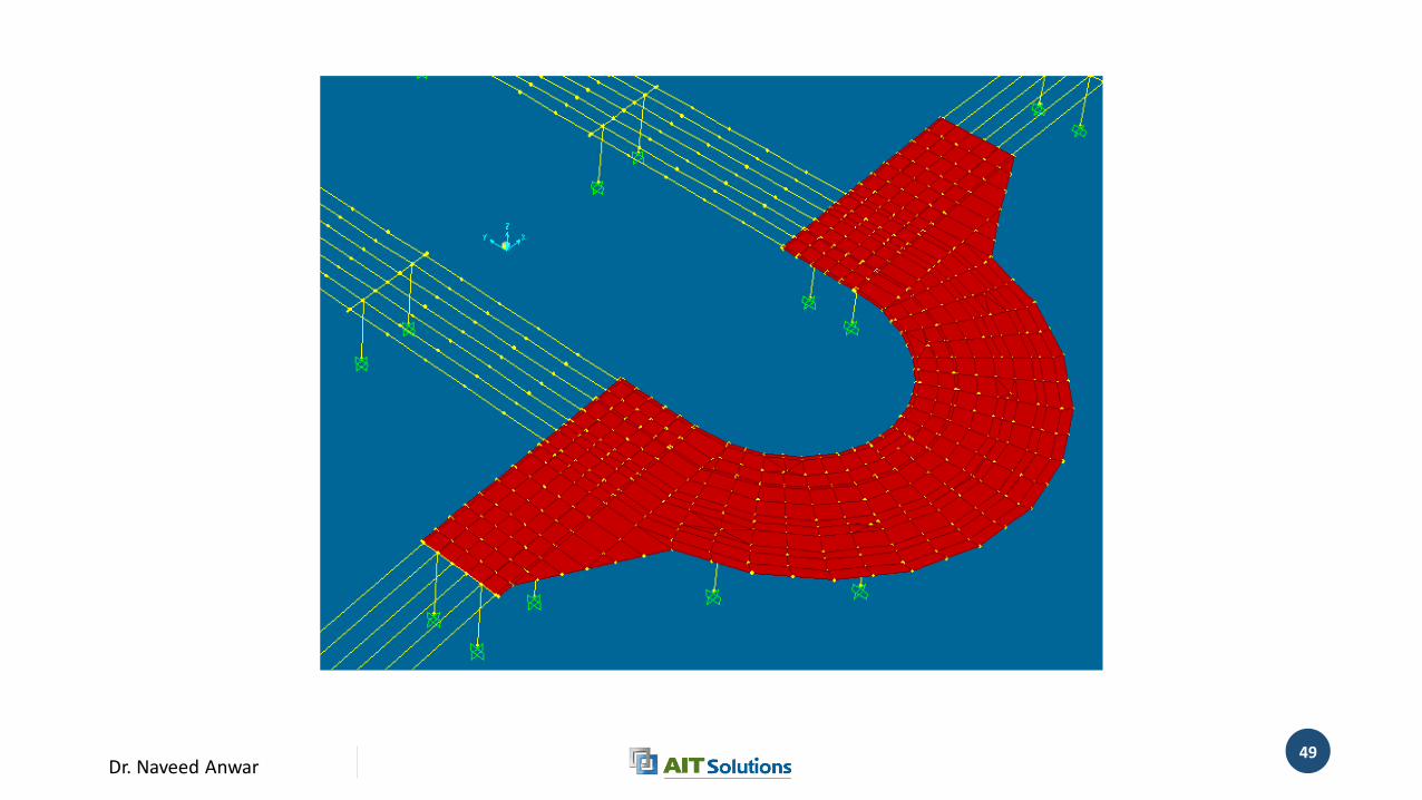
Dr. Naveed Anwar49
Dr. Naveed Anwar50
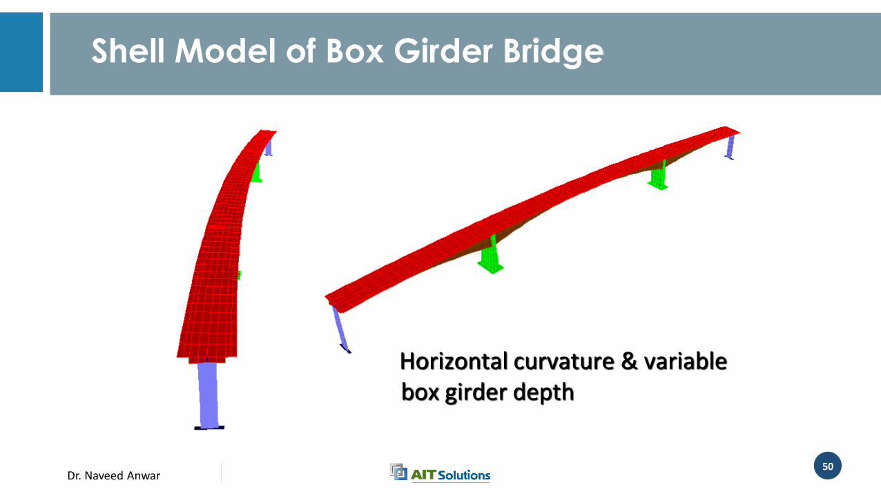
Shell Model of Box Girder Bridge
Horizontal curvature & variable box girder depth
Dr. Naveed Anwar51
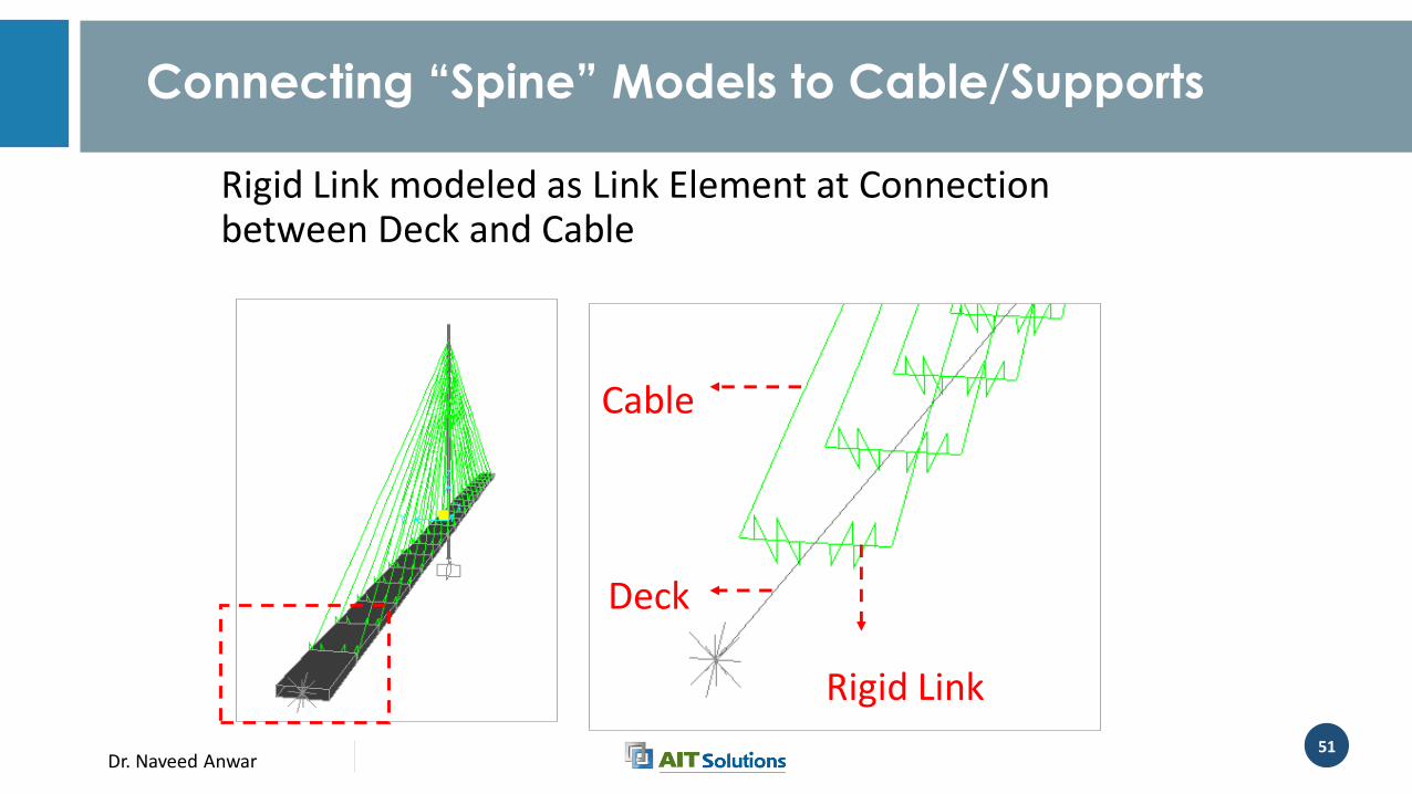
Connecting “Spine” Models to Cable/Supports
Rigid Link modeled as Link Element at Connection between Deck and Cable
Cable
Rigid Link
Deck
Dr. Naveed Anwar52
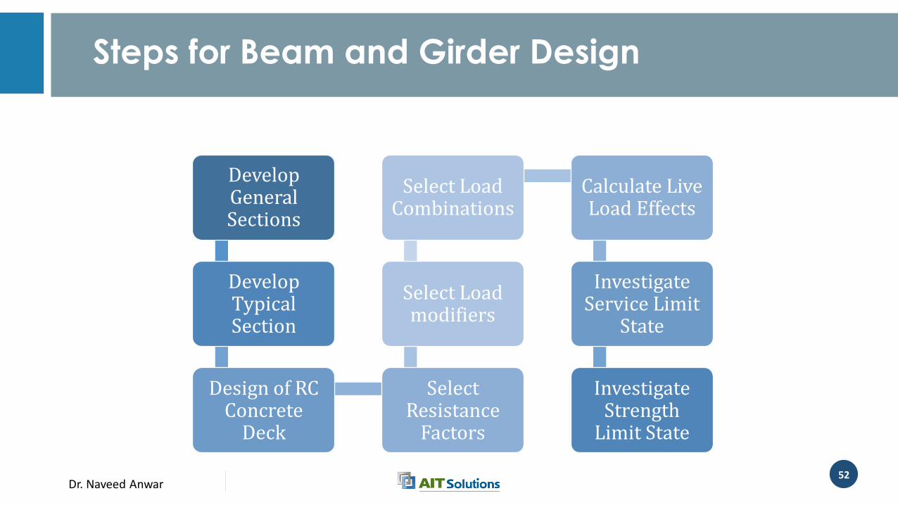
Steps for Beam and Girder Design
Develop General Sections
Develop Typical Section
Design of RC Concrete
Deck
Select Resistance
Factors
Select Load modifiers
Select Load Combinations
Calculate Live Load Effects
Investigate Service Limit
State
Investigate Strength
Limit State
Dr. Naveed Anwar53
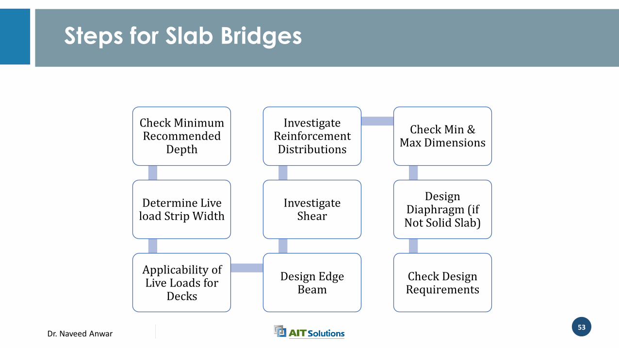
Steps for Slab Bridges
Check Minimum Recommended
Depth
Determine Live load Strip Width
Applicability of Live Loads for
Decks
Design Edge Beam
Investigate Shear
Investigate Reinforcement Distributions
Check Min & Max Dimensions
Design Diaphragm (if Not Solid Slab)
Check Design Requirements

Dr. Naveed Anwar
Handling Prestress Cables
Dr. Naveed Anwar55
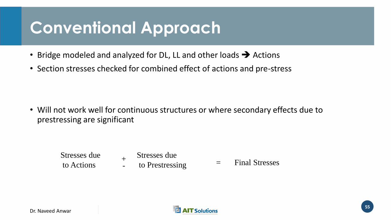
Conventional Approach
• Bridge modeled and analyzed for DL, LL and other loads Actions
• Section stresses checked for combined effect of actions and pre-stress
• Will not work well for continuous structures or where secondary effects due to prestressing are significant
Stresses due
to Actions
Stresses due
to Prestressing Final Stresses+- =
Dr. Naveed Anwar56
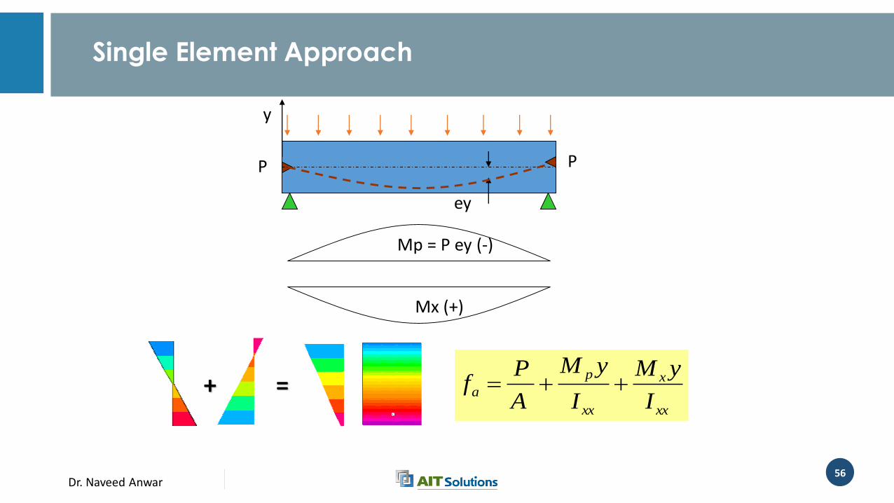
Single Element Approach
Mx (+)
PP
ey
y
Mp = P ey (-)
+ =xx
x
xx
p
aI
yM
I
yM
A
Pf
Dr. Naveed Anwar57
Integrated Approach
• Prestressing is considered as just another load and the final stresses are obtained directly from the final actions• Stresses due to actions Final Stresses
• Will work in every case.
• Drawback:• Prestress has to be estimated right from the start, requires iteration
• A combination of these two approaches is often suitable
Dr. Naveed Anwar58
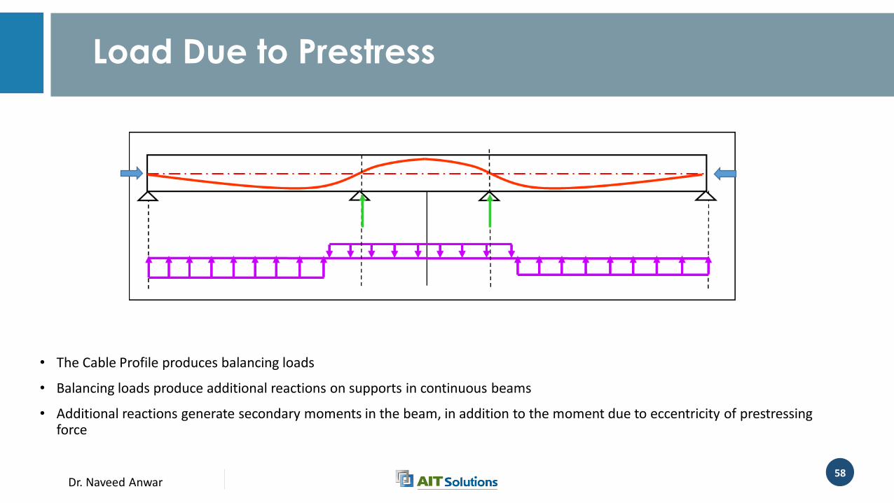
Load Due to Prestress
• The Cable Profile produces balancing loads
• Balancing loads produce additional reactions on supports in continuous beams
• Additional reactions generate secondary moments in the beam, in addition to the moment due to eccentricity of prestressingforce
Dr. Naveed Anwar59
Why to use Integrated Approach?
• The prestress forces are applied to the full structural model the secondary effects are automatically included
• Load Balancing analysis is not required
• Effect of prestressing on the entire structure is evaluated including the continuity, stiffness, shortening, shear lag, eccentricities, etc.
• Most software have the ability to compute stresses and stress profiles for computed actions so no separate stress calculations are needed
Dr. Naveed Anwar60
Why to use Integrated Approach?
• Effects of sequential construction, staged prestressing, etc. can be carried out more comprehensively
• Prestressed structures are more suitable and relevant for linear-elastic analysis mostly used by general FEM Software
• The interaction of axial load, moment and prestress load can be considered more consistently
Dr. Naveed Anwar61
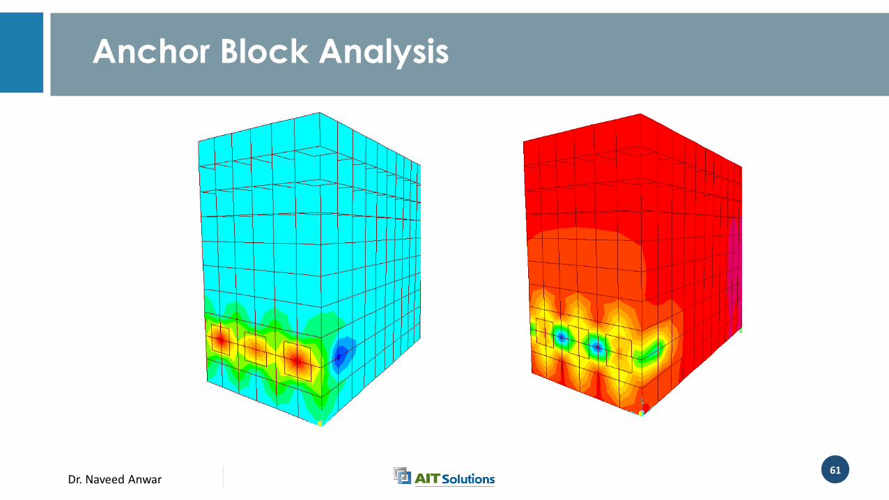
Anchor Block Analysis
Dr. Naveed Anwar62
Design of RC Deck
• Design of decks is carried out on the basis of approximate method of analysis in which the deck is subdivided into strips perpendicular to the supporting components.
• Extreme positive moment in any deck panel between girders shall be taken to apply to all positive moment regions. Similarly, the extreme negative moment over any beam or girder shall be taken to apply to all negative moment regions.
• Strip method is applicable for slab bridges and concrete slabs spanning less than 15.0 ft
Dr. Naveed Anwar63
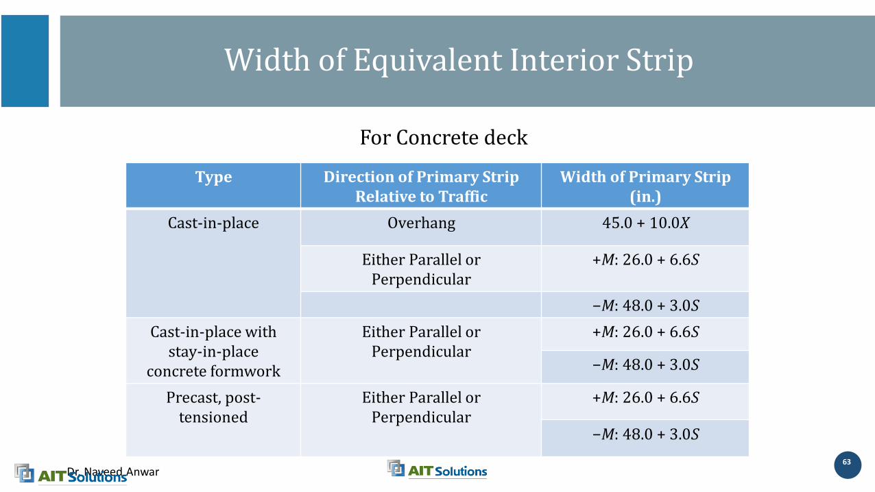
Width of Equivalent Interior Strip
Type Direction of Primary StripRelative to Traffic
Width of Primary Strip (in.)
Cast-in-place Overhang 45.0 + 10.0X
Either Parallel orPerpendicular
+M: 26.0 + 6.6S
−M: 48.0 + 3.0S
Cast-in-place with stay-in-place
concrete formwork
Either Parallel orPerpendicular
+M: 26.0 + 6.6S
−M: 48.0 + 3.0S
Precast, post-tensioned
Either Parallel orPerpendicular
+M: 26.0 + 6.6S
−M: 48.0 + 3.0S
For Concrete deck

Dr. Naveed Anwar64
Type Direction of Primary StripRelative to Traffic
Width of Primary Strip (in.)
Open grid Main Bars 1.25P + 4.0Sb
Filled or partially filled gridk
Main Bars Article 4.6.2.1.8 applies (LRFD Bridge Design
Specification)
Unfilled, composite grids
Main Bars Article 4.6.2.1.8 applies (LRFD Bridge Design
Specification)
For Steel Deck
Width of Equivalent Interior Strip
Dr. Naveed Anwar
Steps of Bridge Substructure Design
Dr. Naveed Anwar66
66
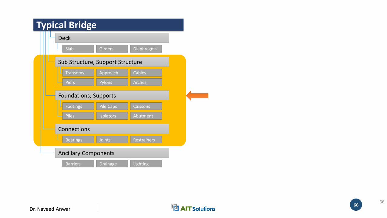
Sub Structure, Support Structure
Connections
Ancillary Components
Deck
Slab Girders Diaphragms
Transoms
Piers
Cables
Arches
Foundations, Supports
Footings Pile Caps
Piles
Caissons
Pylons
Bearings Joints Restrainers
Isolators
Approach
Abutment
Typical Bridge
Barriers Drainage Lighting
Dr. Naveed Anwar67
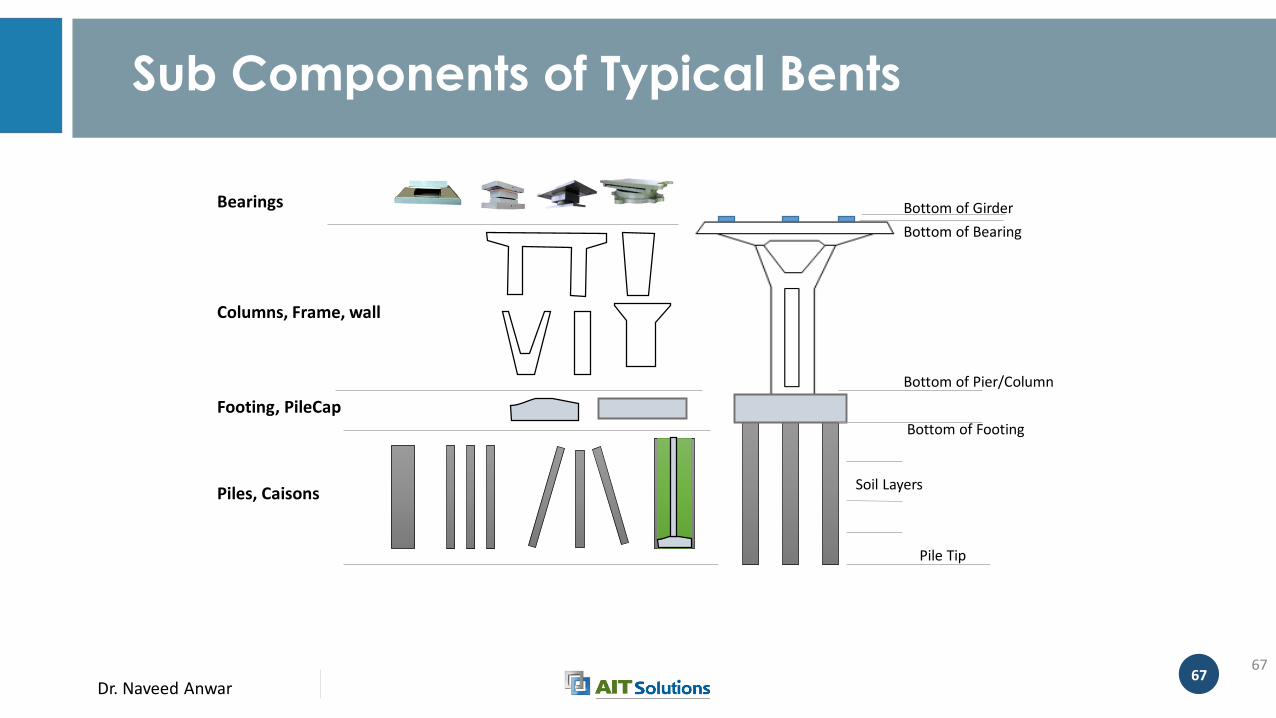
Sub Components of Typical Bents
67
Bottom of Girder
Bottom of Bearing
Bottom of Pier/Column
Bottom of Footing
Pile Tip
Soil Layers
Bearings
Columns, Frame, wall
Footing, PileCap
Piles, Caisons
Dr. Naveed Anwar
Modeling of Pier Bents
Dr. Naveed Anwar69
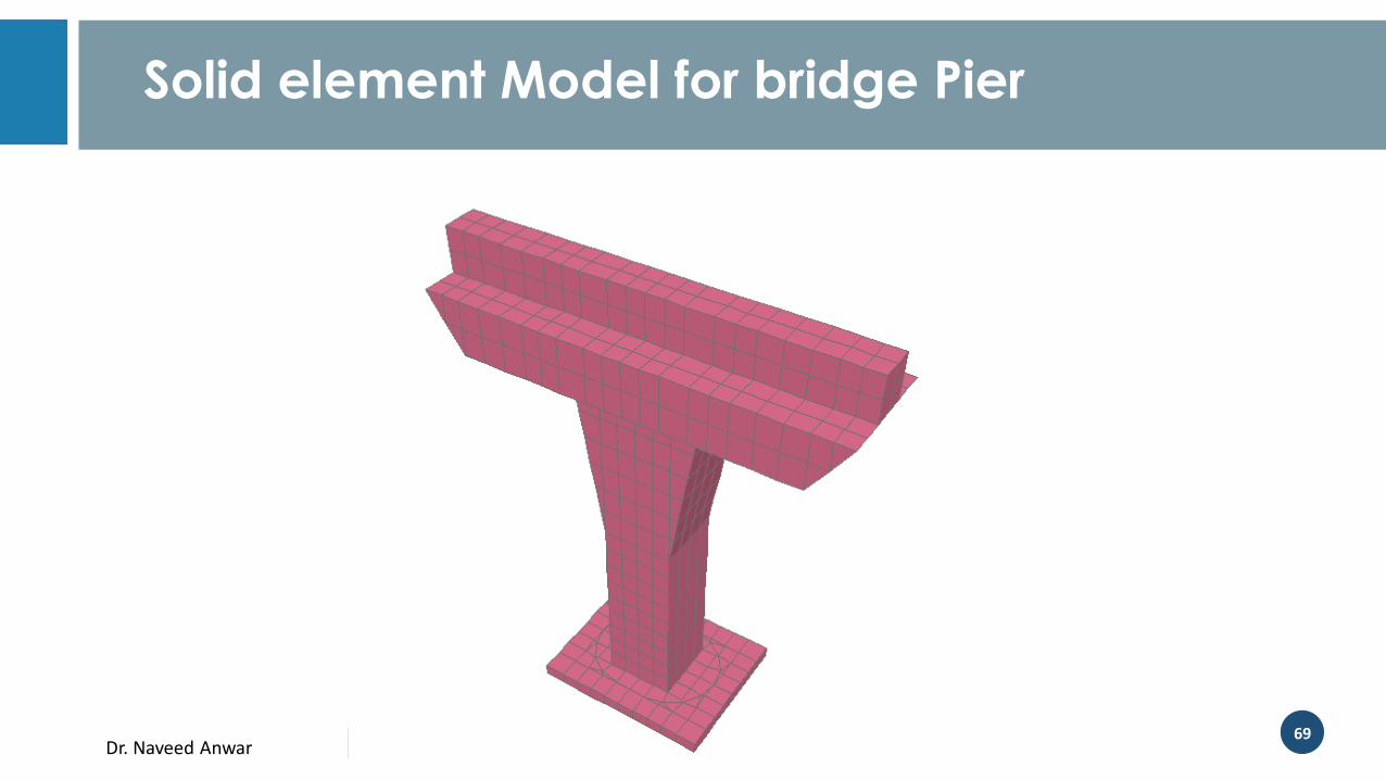
Solid element Model for bridge Pier
Dr. Naveed Anwar70
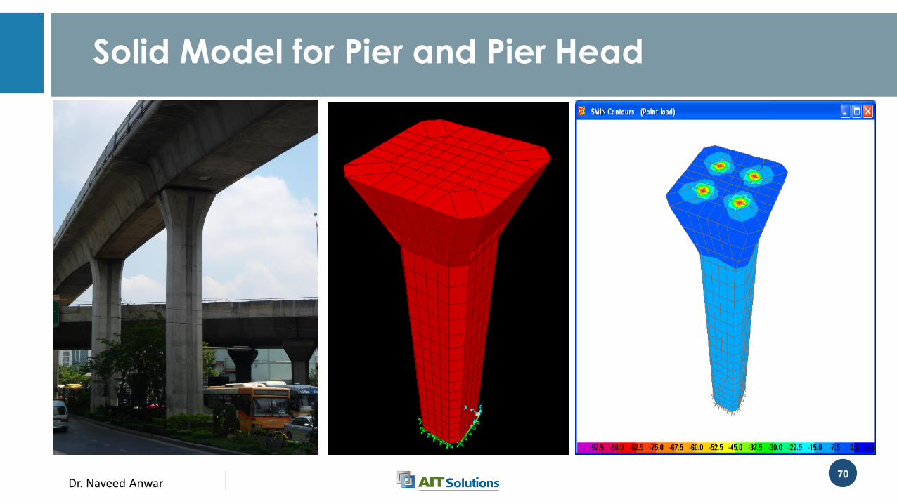
Solid Model for Pier and Pier Head
Dr. Naveed Anwar71
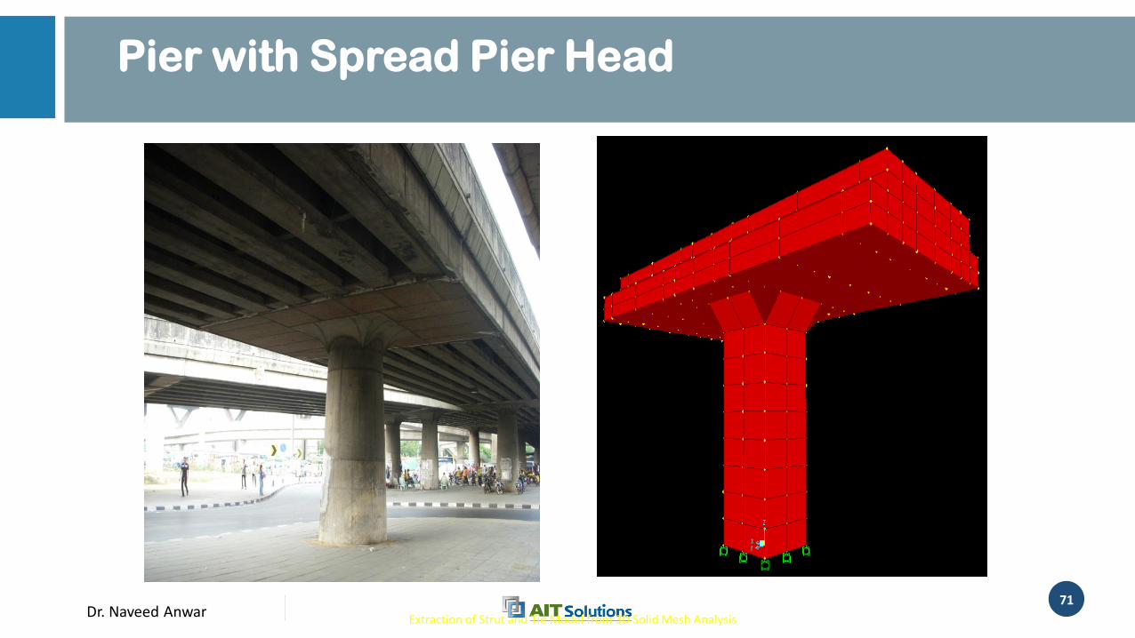
Pier with Spread Pier Head
Extraction of Strut and Tie Model from 3D Solid Mesh Analysis
Solid element
model
Dr. Naveed Anwar72
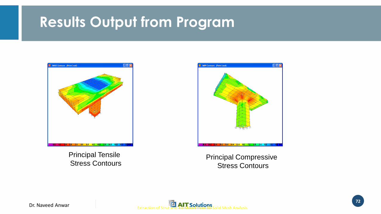
Extraction of Strut and Tie Model from 3D Solid Mesh Analysis
Principal Compressive
Stress Contours
Principal Tensile
Stress Contours
Results Output from Program
Dr. Naveed Anwar73
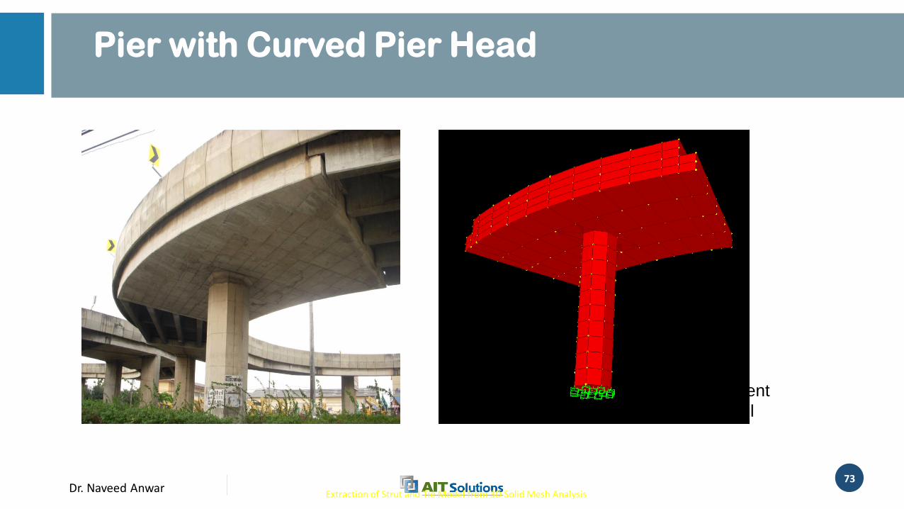
Pier with Curved Pier Head
Extraction of Strut and Tie Model from 3D Solid Mesh Analysis
Solid element
model
Dr. Naveed Anwar74
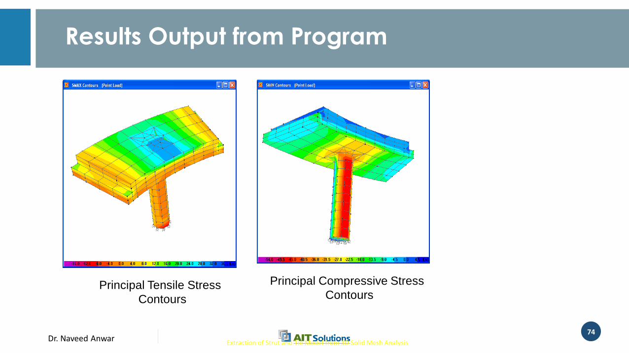
Extraction of Strut and Tie Model from 3D Solid Mesh Analysis
Principal Compressive Stress
ContoursPrincipal Tensile Stress
Contours
Results Output from Program
Dr. Naveed Anwar75
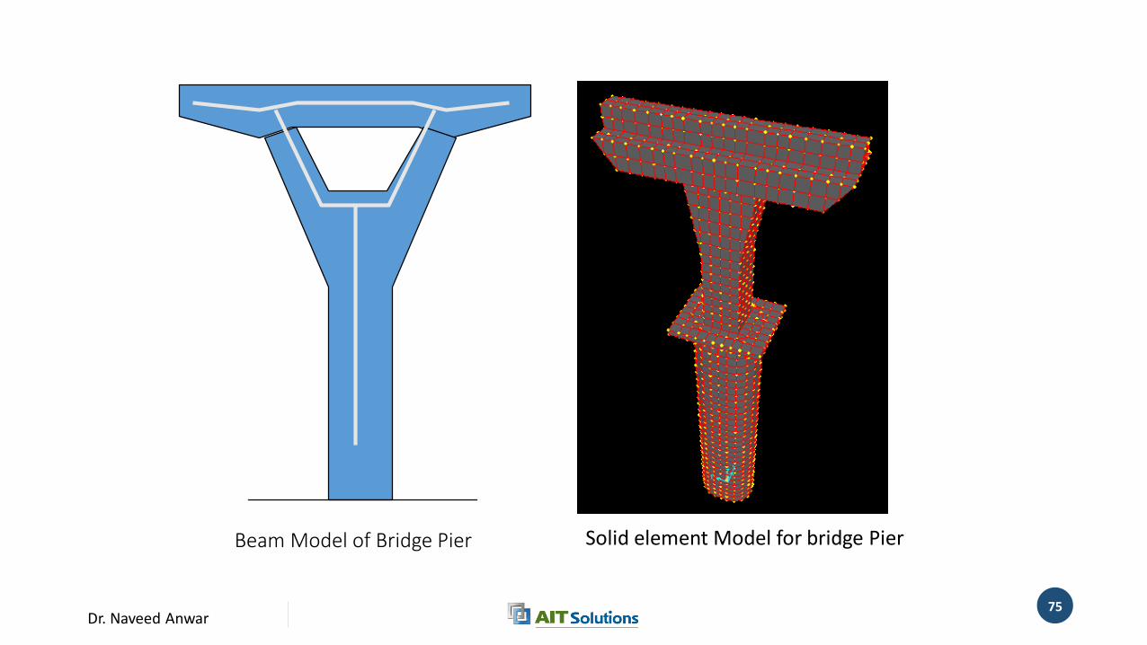
Beam Model of Bridge Pier Solid element Model for bridge Pier
Dr. Naveed Anwar76
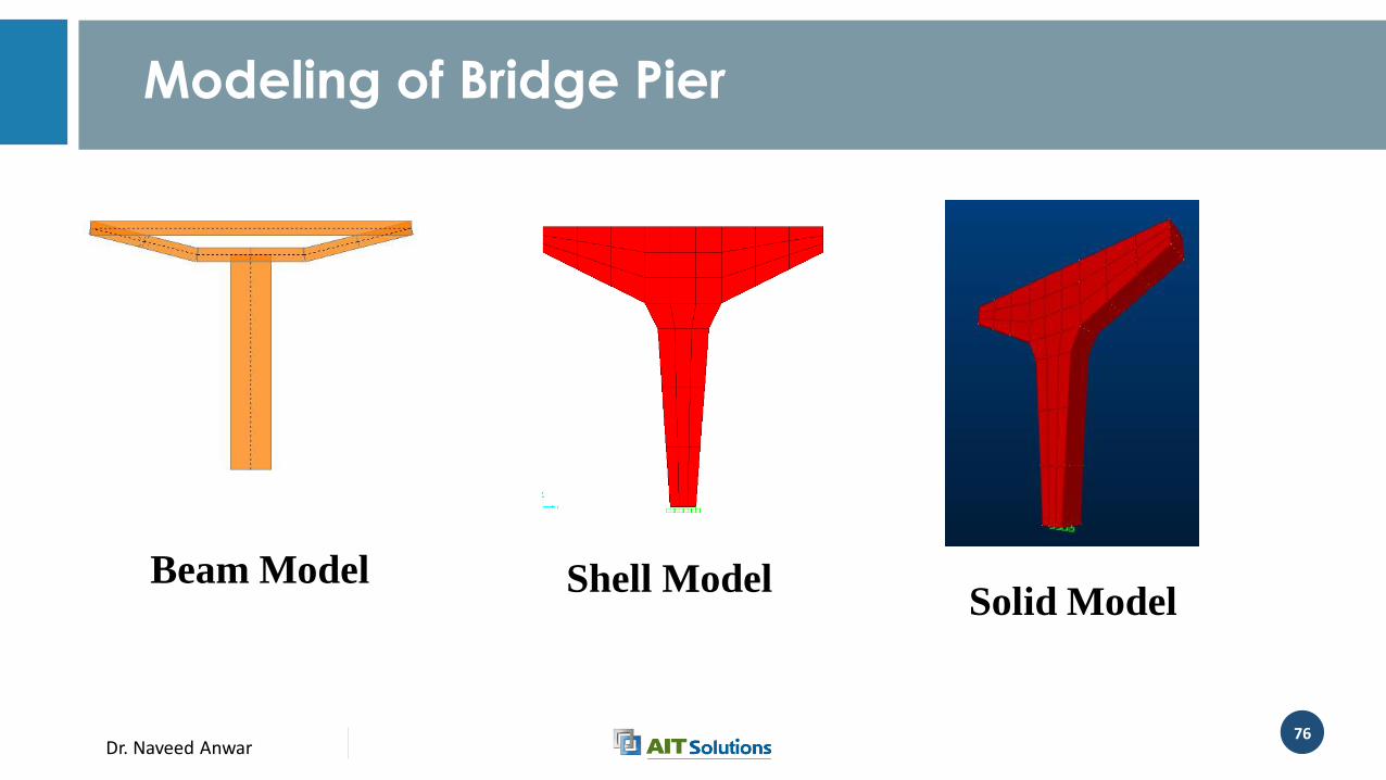
Modeling of Bridge Pier
Beam Model Shell Model Solid Model
Dr. Naveed Anwar77
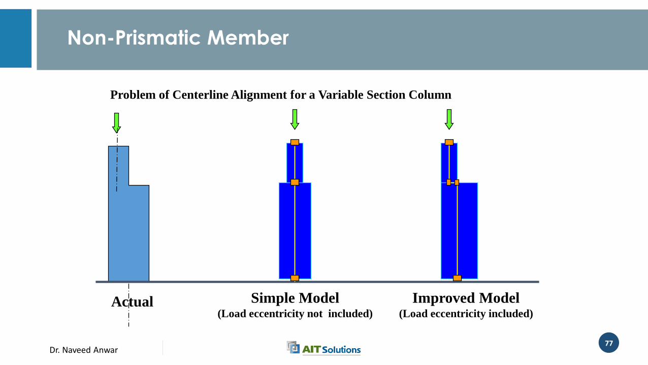
Problem of Centerline Alignment for a Variable Section Column
Actual Improved Model(Load eccentricity included)
Simple Model(Load eccentricity not included)
Non-Prismatic Member

Dr. Naveed Anwar
Modeling of Foundations
Dr. Naveed Anwar79
Sub-Structure
• The Structural Members and Systems below the Bearings or the Main Deck or the Main Framing
• Actual division depends on bridge type
• May include:• Lateral Framing System
• Piers
• Foundations
Dr. Naveed Anwar80
Modeling of Supports
• Actual Supports• Isolated Footings
• Combined Footings
• Rafts
• Pile Cap
• Special Supports
• Pile Piers
• Caissons
Dr. Naveed Anwar81
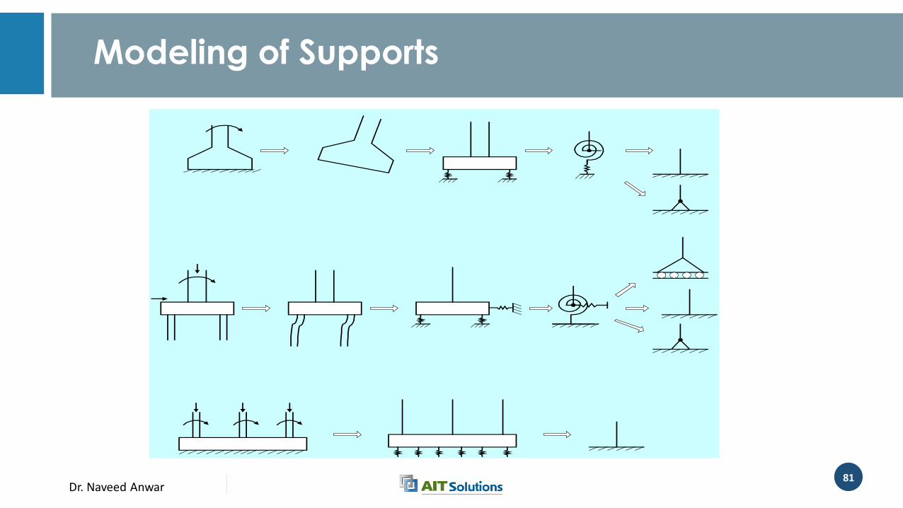
Modeling of Supports
Dr. Naveed Anwar82
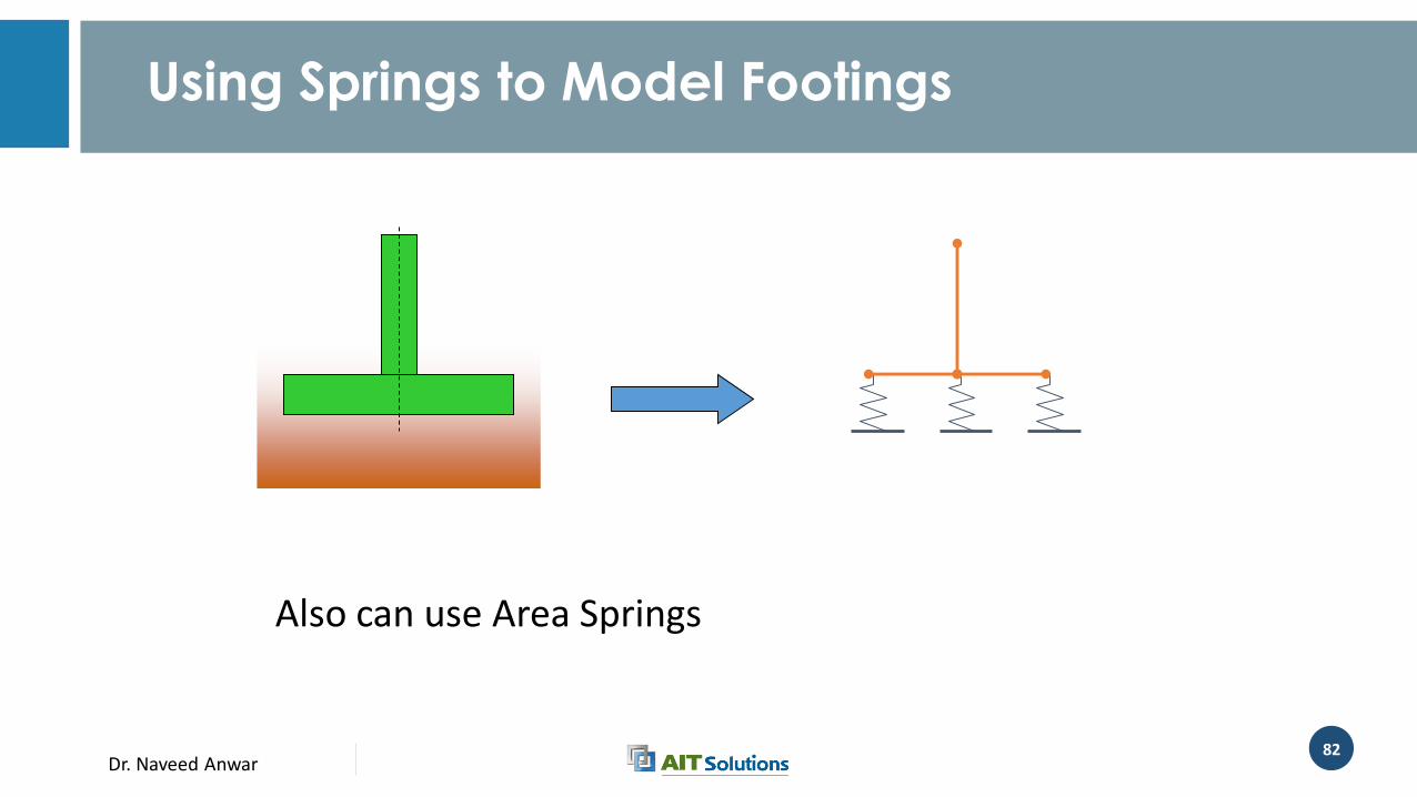
Using Springs to Model Footings
Also can use Area Springs
Dr. Naveed Anwar83
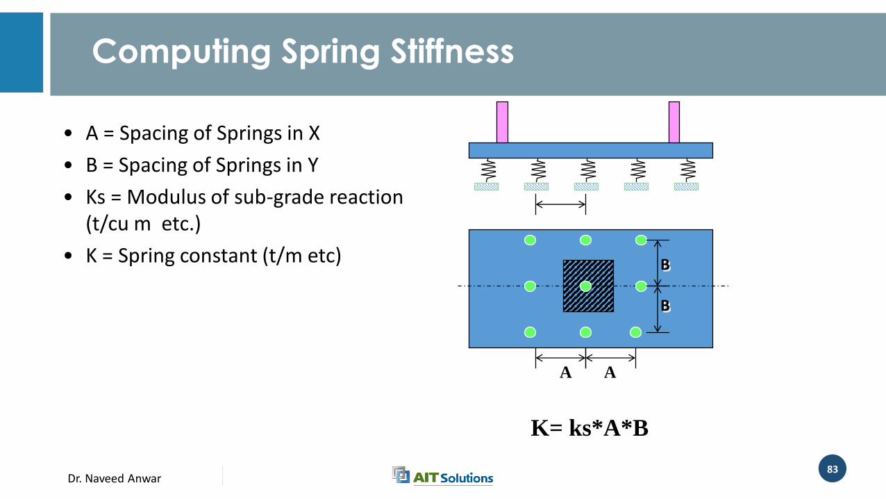
• A = Spacing of Springs in X
• B = Spacing of Springs in Y
• Ks = Modulus of sub-grade reaction (t/cu m etc.)
• K = Spring constant (t/m etc)
A
K= ks*A*B
B
A
B
Computing Spring Stiffness
Dr. Naveed Anwar84
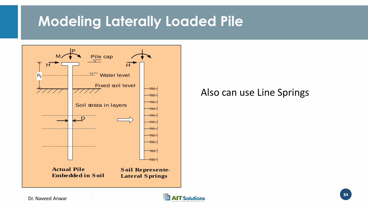
Modeling Laterally Loaded Pile
Soil strata in layers
D
M
H
P
Pile cap
Fixed soil level
hf
Actual Pile
Embedded in S oilS oil Represented by
Lateral S prings
H
Beam or truss
element (Si)
Beam
elements (Pi)
MH 1
2
4
6
3
5
7
Frame Model
N+1
Water level hf
hs
Ls
hs
1
N
2 Also can use Line Springs
Dr. Naveed Anwar85
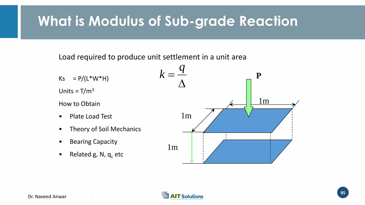
Ks = P/(L*W*H)
Units = T/m3
How to Obtain
• Plate Load Test
• Theory of Soil Mechanics
• Bearing Capacity
• Related g, N, qc etc1m
1m
1m
P
Load required to produce unit settlement in a unit area
What is Modulus of Sub-grade Reaction
qk
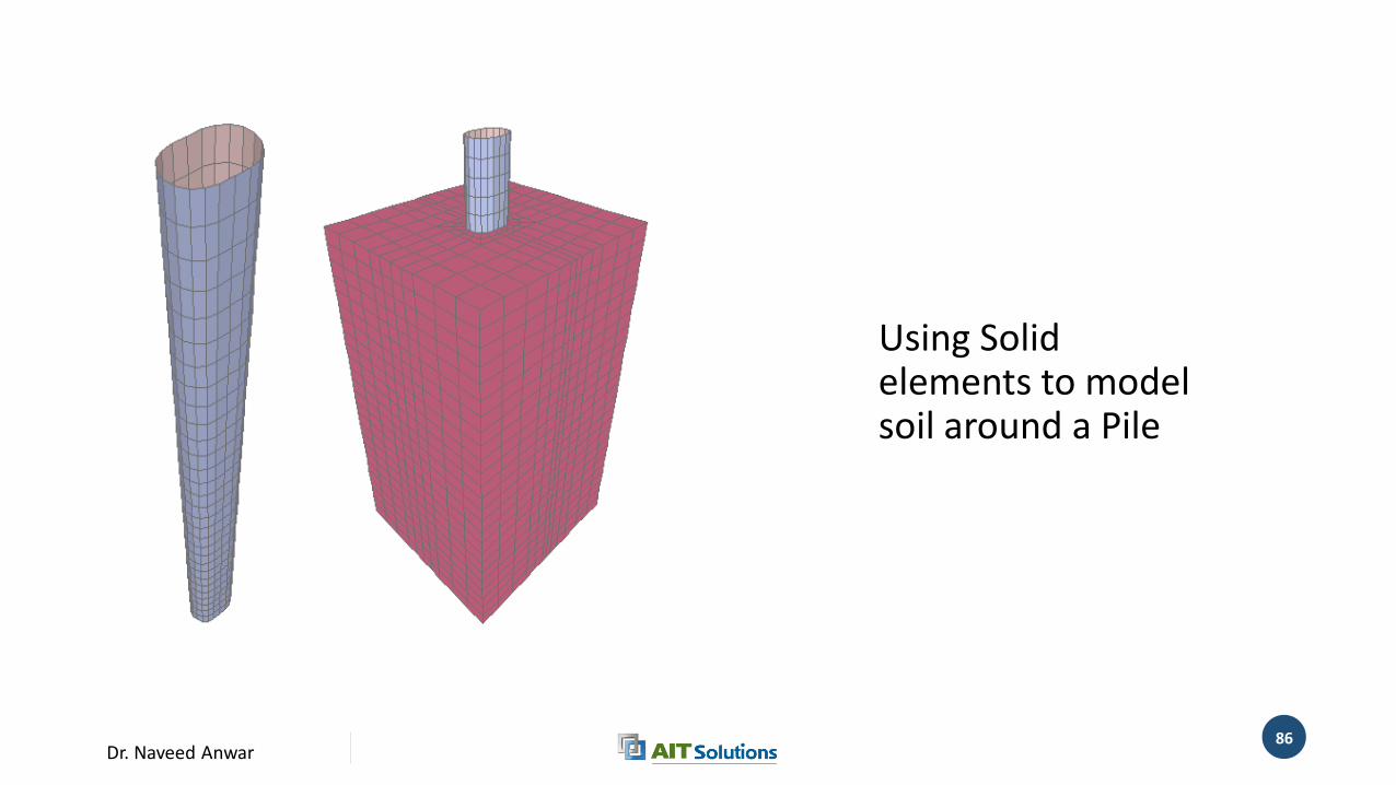
Dr. Naveed Anwar86
Using Solid elements to model soil around a Pile
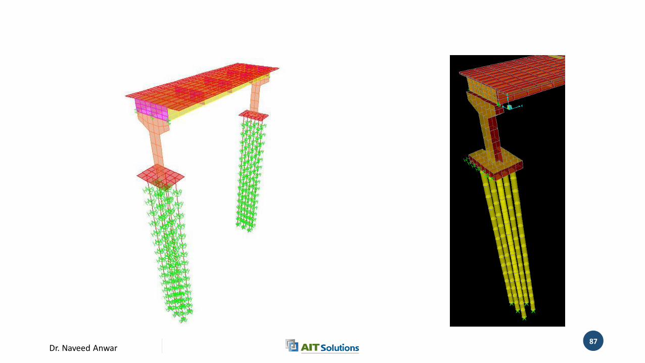
Dr. Naveed Anwar87
Dr. Naveed Anwar88
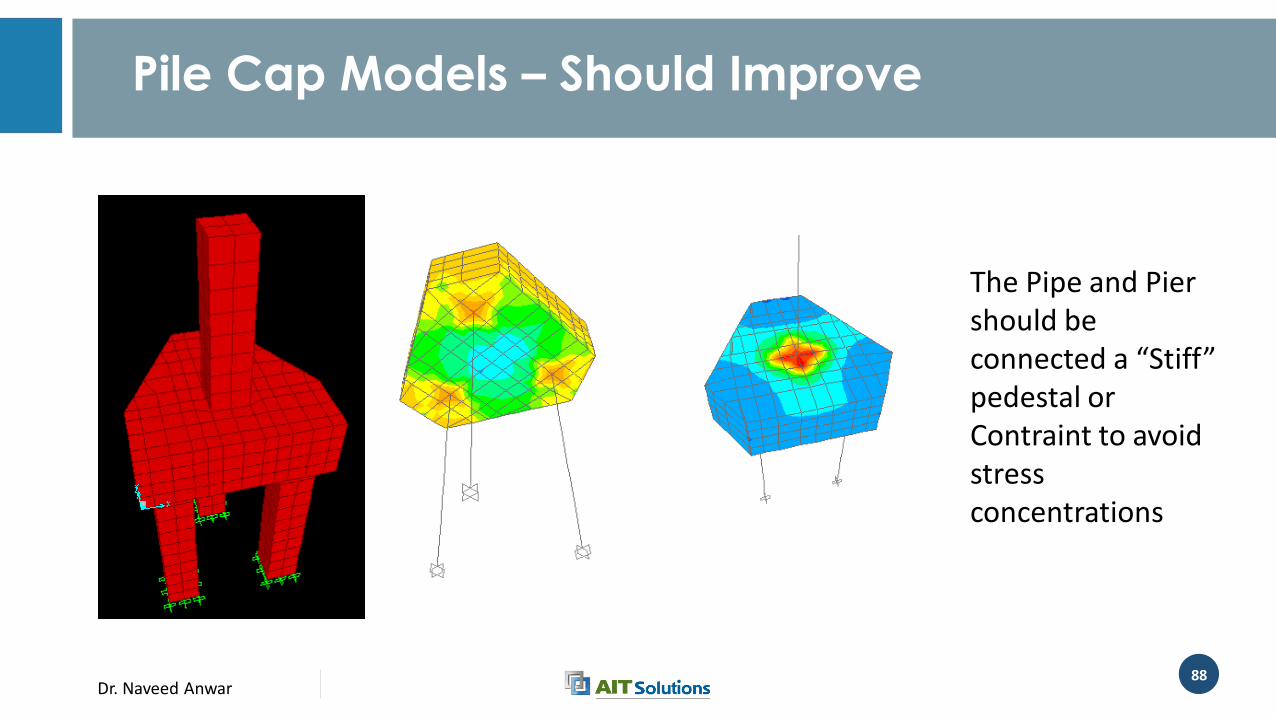
Pile Cap Models – Should Improve
The Pipe and Pier should be connected a “Stiff” pedestal or Contraint to avoid stress concentrations
Dr. Naveed Anwar89
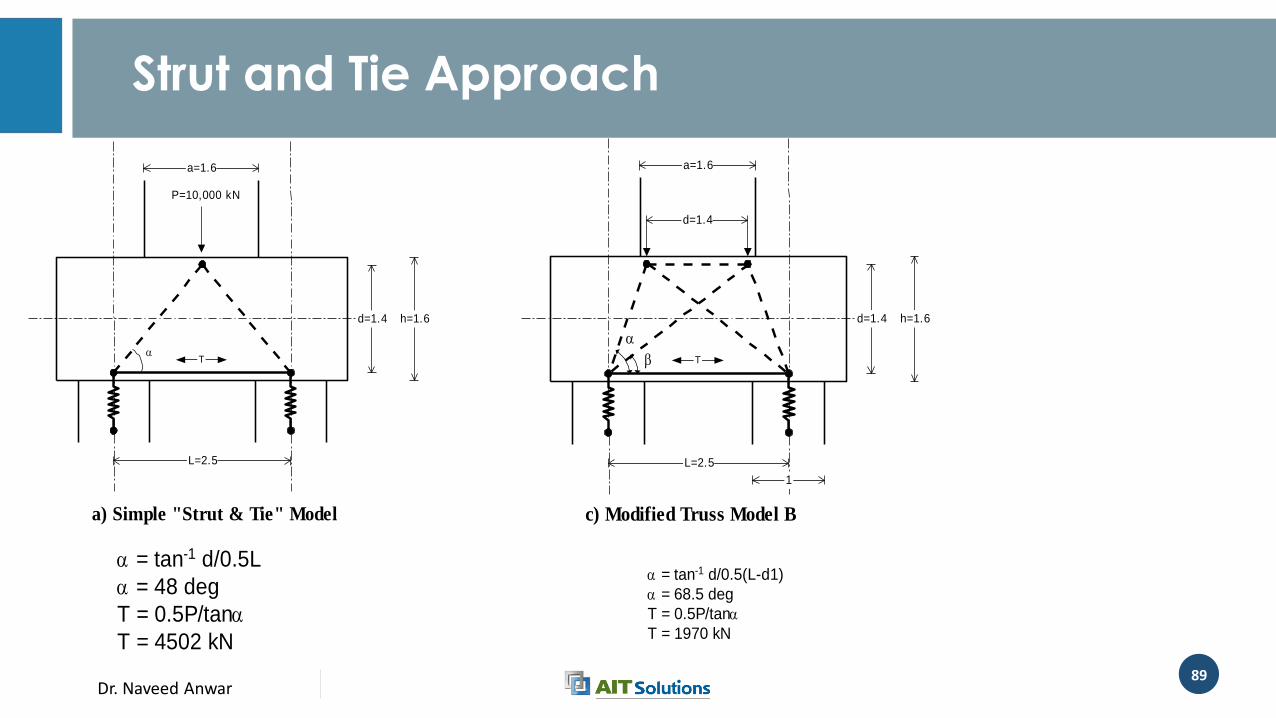
Strut and Tie Approach
L=2.5
a=1.6
d=1.4 h=1.6
T
P=10,000 kN
a) Simple "Strut & Tie" Model c) Modified Truss Model B
L=2.5
a=1.6
d=1.4
d=1.4 h=1.6
T
1
= tan-1 d/0.5L
= 48 deg
T = 0.5P/tan
T = 4502 kN
= tan-1 d/0.5(L-d1)
= 68.5 deg
T = 0.5P/tan
T = 1970 kN
Dr. Naveed Anwar90
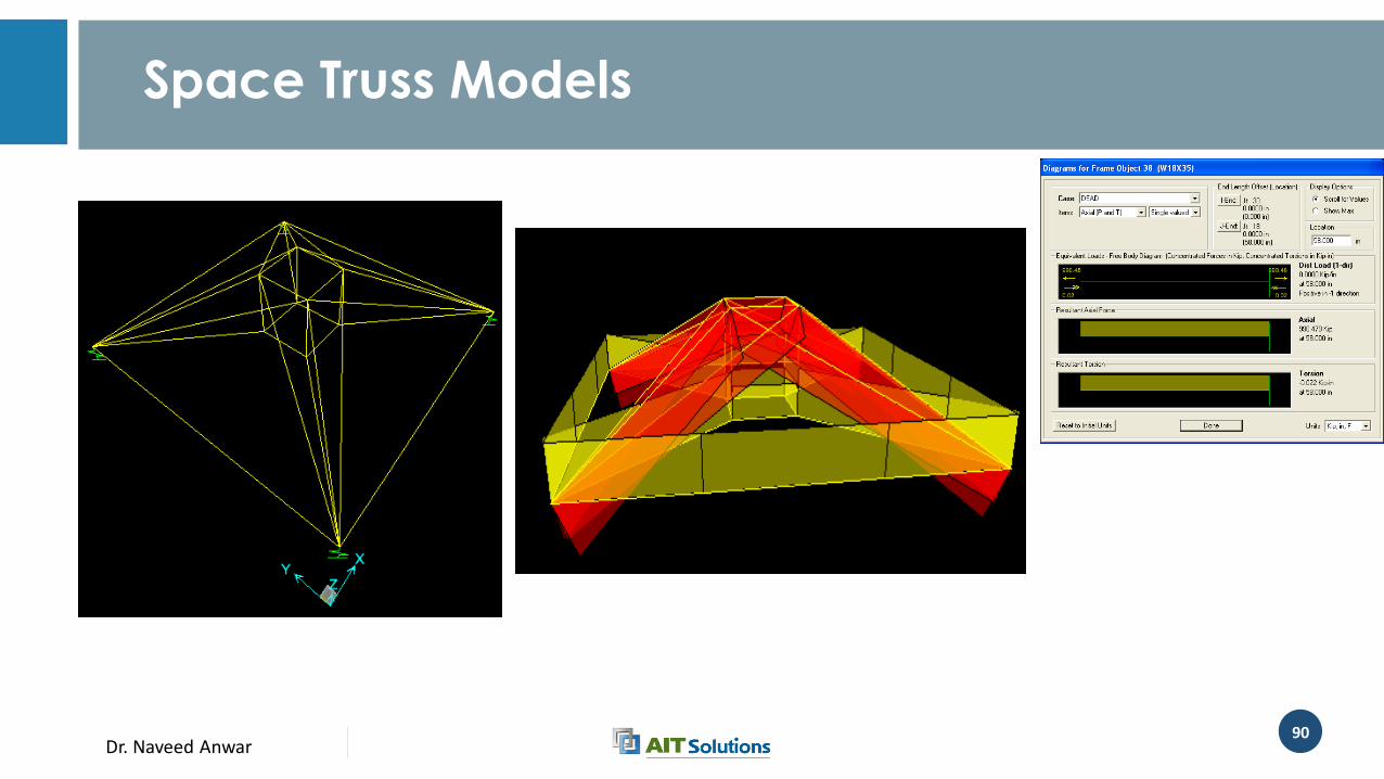
Space Truss Models
Dr. Naveed Anwar91
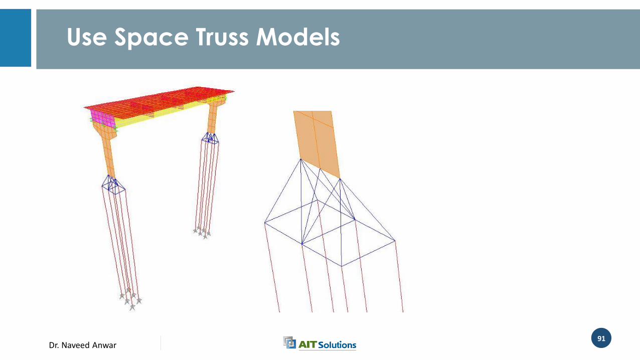
Use Space Truss Models

Dr. Naveed Anwar
Bridge Bearings and Joints
Dr. Naveed Anwar93
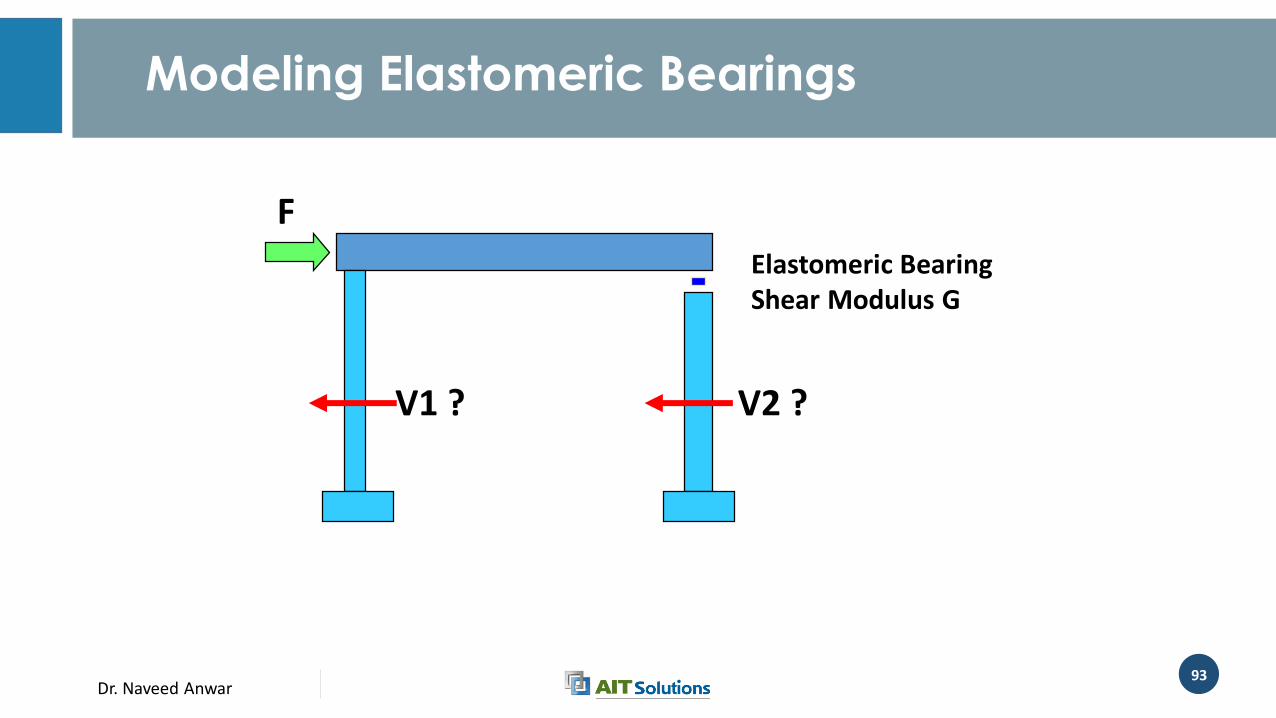
F
V1 ? V2 ?
Elastomeric BearingShear Modulus G
Modeling Elastomeric Bearings
Dr. Naveed Anwar94
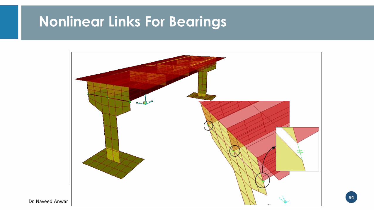
Nonlinear Links For Bearings
Dr. Naveed Anwar95
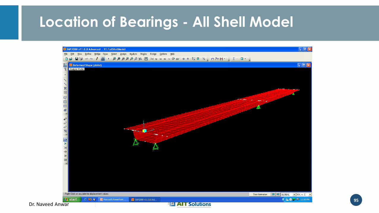
Location of Bearings - All Shell Model
Dr. Naveed Anwar96
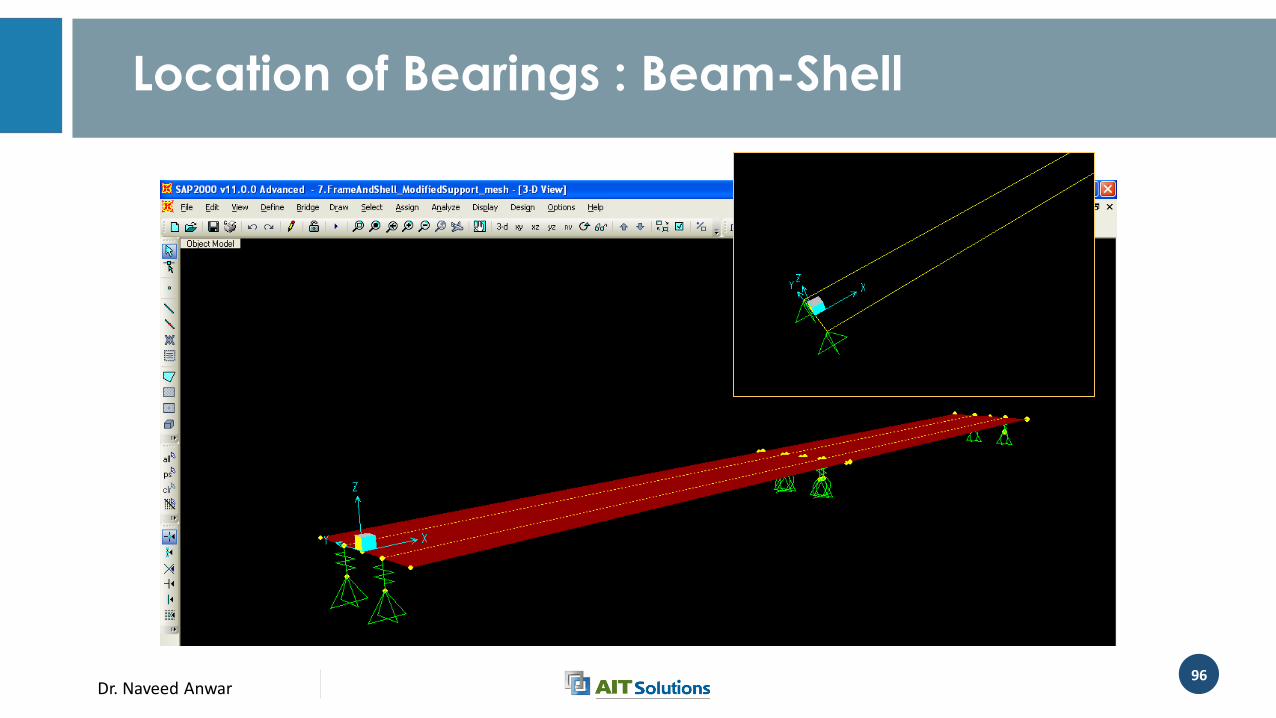
Location of Bearings : Beam-Shell
Dr. Naveed Anwar97
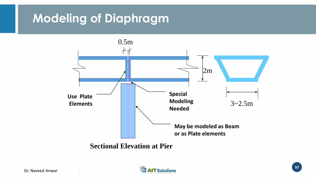
Modeling of Diaphragm
2m
3~2.5m
0.5m
Use Plate Elements
Special Modeling Needed
May be modeled as Beam or as Plate elements
Sectional Elevation at Pier
Dr. Naveed Anwar98
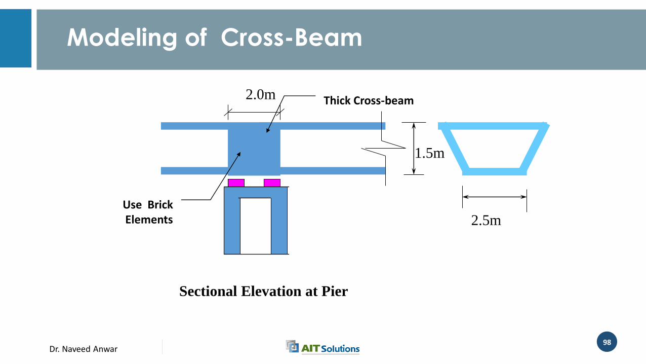
Modeling of Cross-Beam
1.5m
2.5m
2.0m
Use Brick Elements
Sectional Elevation at Pier
Thick Cross-beam
Dr. Naveed Anwar99
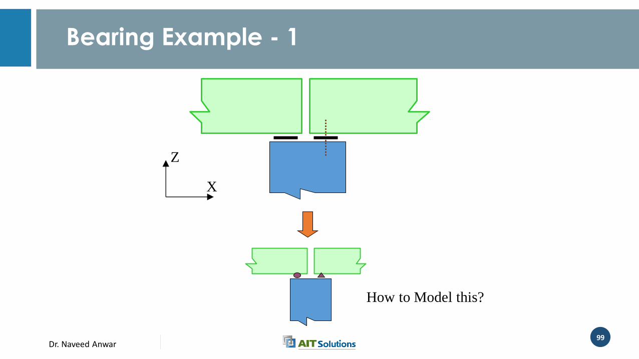
Bearing Example - 1
X
Z
How to Model this?
Dr. Naveed Anwar100
Modeling of Joints and Bearings
• In finite element models, by default all element connected to a node share the Nodal Degree of Freedom (DOF)
• This is suitable for fully connected structural members
• At Joints, full connection may not be available or desired
• We can either “release” or “constrain” the DOF to change this default behavior and to model joints
Dr. Naveed Anwar101
Bearing and Expansion Joints
• Effectively Modeling of Support conditions at bearing and expansion joints requires careful consideration of the continuity of each translation and rotational components of displacement.
• Joints may behave linearly or non linearly
• Linear Joints• Roller, Pin
• Elastomeric Pads
• Nonlinear Joints• Expansion Joint, Gap
• Restraining Block, Gap or Hook
Dr. Naveed Anwar102
Bearing and Expansion Joints
• Degrees-of-freedom representing discontinuous components must be disconnected
• Stiffness/ flexibility of bearing pads and other connections should be modeled

Dr. Naveed Anwar103
Bearing and Expansion Joints
• Effectively Modeling of Support conditions at bearing and expansion joints requires careful consideration of the continuity of each translation and rotational components of displacement.
• Joints may behave linearly or non linearly
• Linear Joints• Roller, Pin
• Elastomeric Pads
• Nonlinear Joints• Expansion Joint, Gap
• Restraining Block, Gap or Hook
Dr. Naveed Anwar104
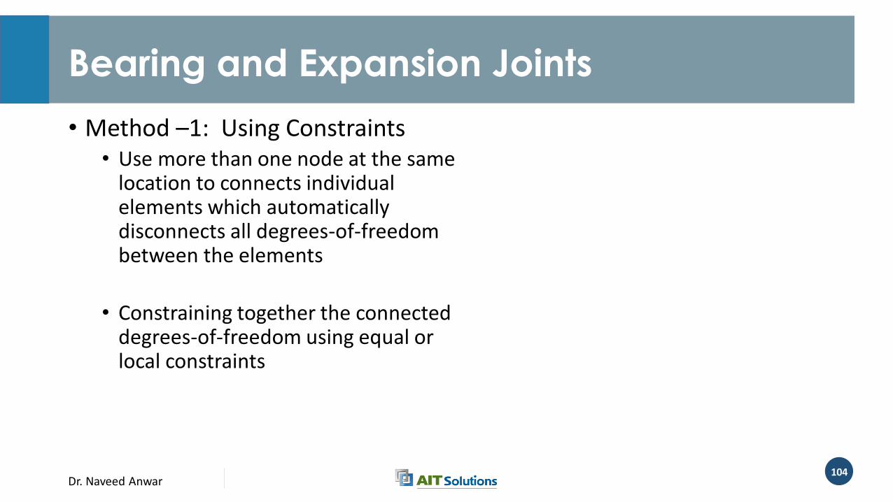
Bearing and Expansion Joints
• Method –1: Using Constraints• Use more than one node at the same
location to connects individual elements which automatically disconnects all degrees-of-freedom between the elements
• Constraining together the connected degrees-of-freedom using equal or local constraints
Dr. Naveed Anwar105
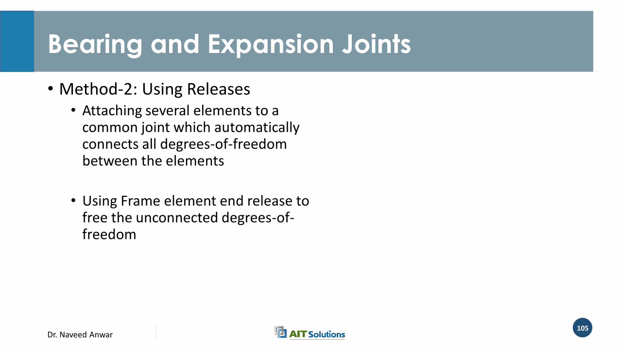
Bearing and Expansion Joints
• Method-2: Using Releases• Attaching several elements to a
common joint which automatically connects all degrees-of-freedom between the elements
• Using Frame element end release to free the unconnected degrees-of-freedom
Dr. Naveed Anwar106
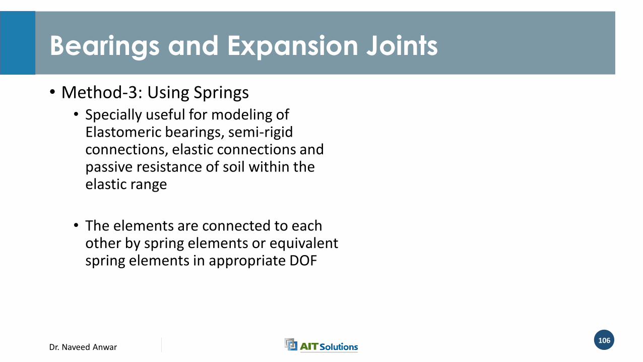
Bearings and Expansion Joints
• Method-3: Using Springs• Specially useful for modeling of
Elastomeric bearings, semi-rigid connections, elastic connections and passive resistance of soil within the elastic range
• The elements are connected to each other by spring elements or equivalent spring elements in appropriate DOF
Dr. Naveed Anwar107
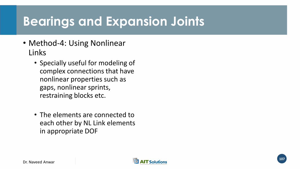
Bearings and Expansion Joints
• Method-4: Using Nonlinear Links• Specially useful for modeling of
complex connections that have nonlinear properties such as gaps, nonlinear sprints, restraining blocks etc.
• The elements are connected to each other by NL Link elements in appropriate DOF
Dr. Naveed Anwar108
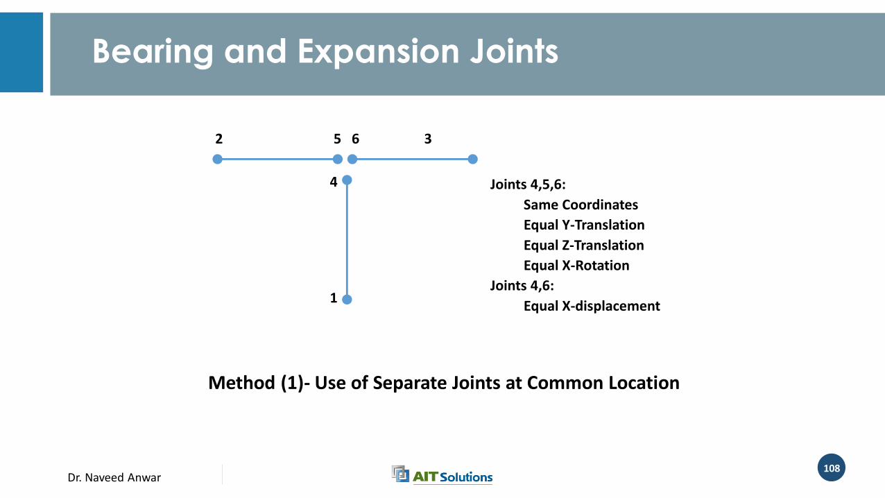
Bearing and Expansion Joints
62 5
4
1
3
Method (1)- Use of Separate Joints at Common Location
Joints 4,5,6:
Same Coordinates
Equal Y-Translation
Equal Z-Translation
Equal X-Rotation
Joints 4,6:
Equal X-displacement
Dr. Naveed Anwar109
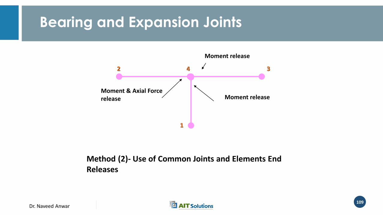
Bearing and Expansion Joints
Method (2)- Use of Common Joints and Elements End Releases
Moment & Axial Force release
2 4
1
3
Moment release
Moment release
Dr. Naveed Anwar110
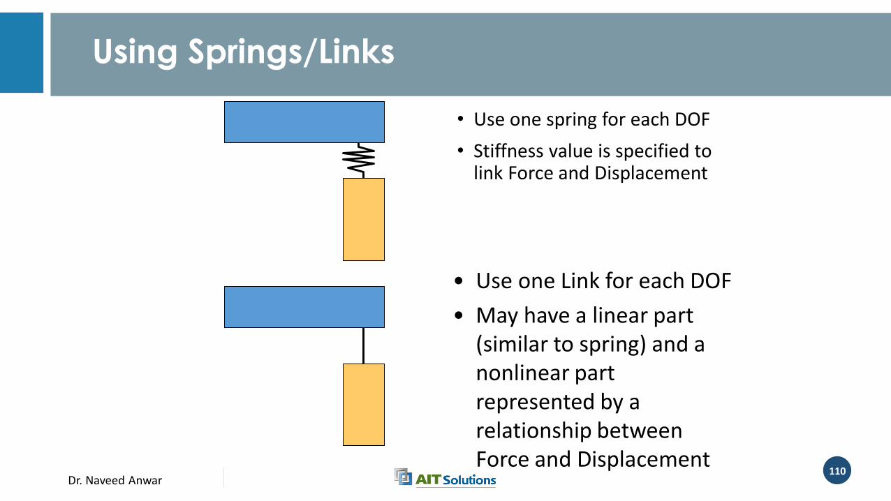
Using Springs/Links
• Use one spring for each DOF
• Stiffness value is specified to link Force and Displacement
• Use one Link for each DOF
• May have a linear part (similar to spring) and a nonlinear part represented by a relationship between Force and Displacement
Dr. Naveed Anwar111
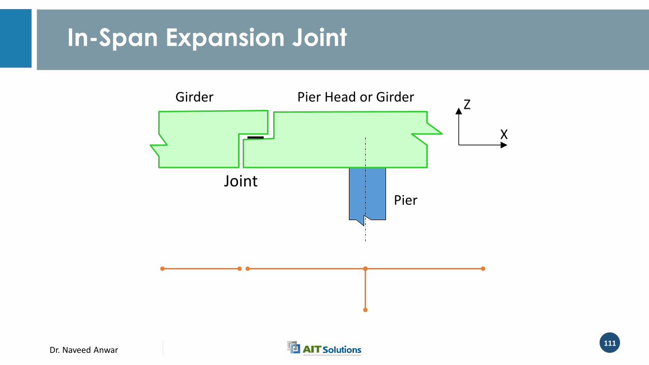
In-Span Expansion Joint
X
Z
Pier
Pier Head or GirderGirder
Joint
Dr. Naveed Anwar112
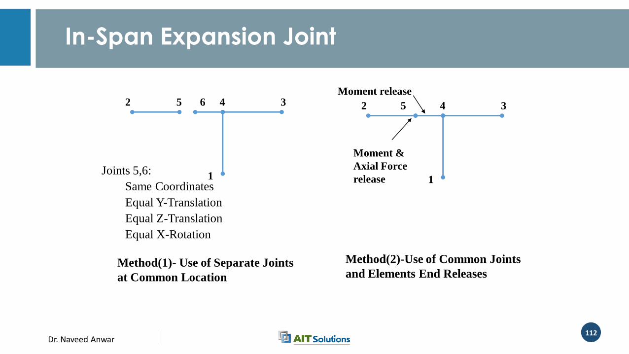
In-Span Expansion Joint
32 5 6 4
1
Method(1)- Use of Separate Joints
at Common Location
Joints 5,6:
Same Coordinates
Equal Y-Translation
Equal Z-Translation
Equal X-Rotation
32 5 4
1
Method(2)-Use of Common Joints
and Elements End Releases
Moment &
Axial Force
release
Moment release
Dr. Naveed Anwar
Modeling of Abutments
Dr. Naveed Anwar114
Role of Abutments
• For Gravity Loads• Retain the soil on road way side
• Support the vertical component of girder reaction
• Accommodate bearing movement due to temperature change and elastic shortenings
• Provide restrain for lateral reaction due to longitudinal loads
• Additional Role for Seismic Loads• Impart and resist longitudinal loads due to mass-acceleration
Dr. Naveed Anwar115
Abutment Behavior
• Behavior depends on the type of abutment and intended purpose
• In general, the overall behavior • Subjected to active soil pressure causing over-turning towards the span
• Imparts passive pressure to the soil due to longitudinal forces and movements
• Vertical load transferred to the soil either through retaining wall or through the transom and pile system
Dr. Naveed Anwar116
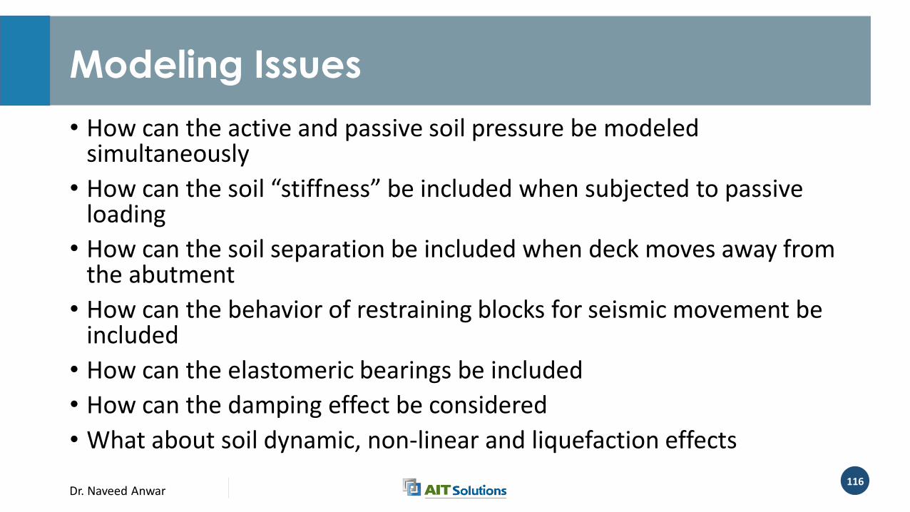
Modeling Issues
• How can the active and passive soil pressure be modeled simultaneously
• How can the soil “stiffness” be included when subjected to passive loading
• How can the soil separation be included when deck moves away from the abutment
• How can the behavior of restraining blocks for seismic movement be included
• How can the elastomeric bearings be included
• How can the damping effect be considered
• What about soil dynamic, non-linear and liquefaction effects
Dr. Naveed Anwar117
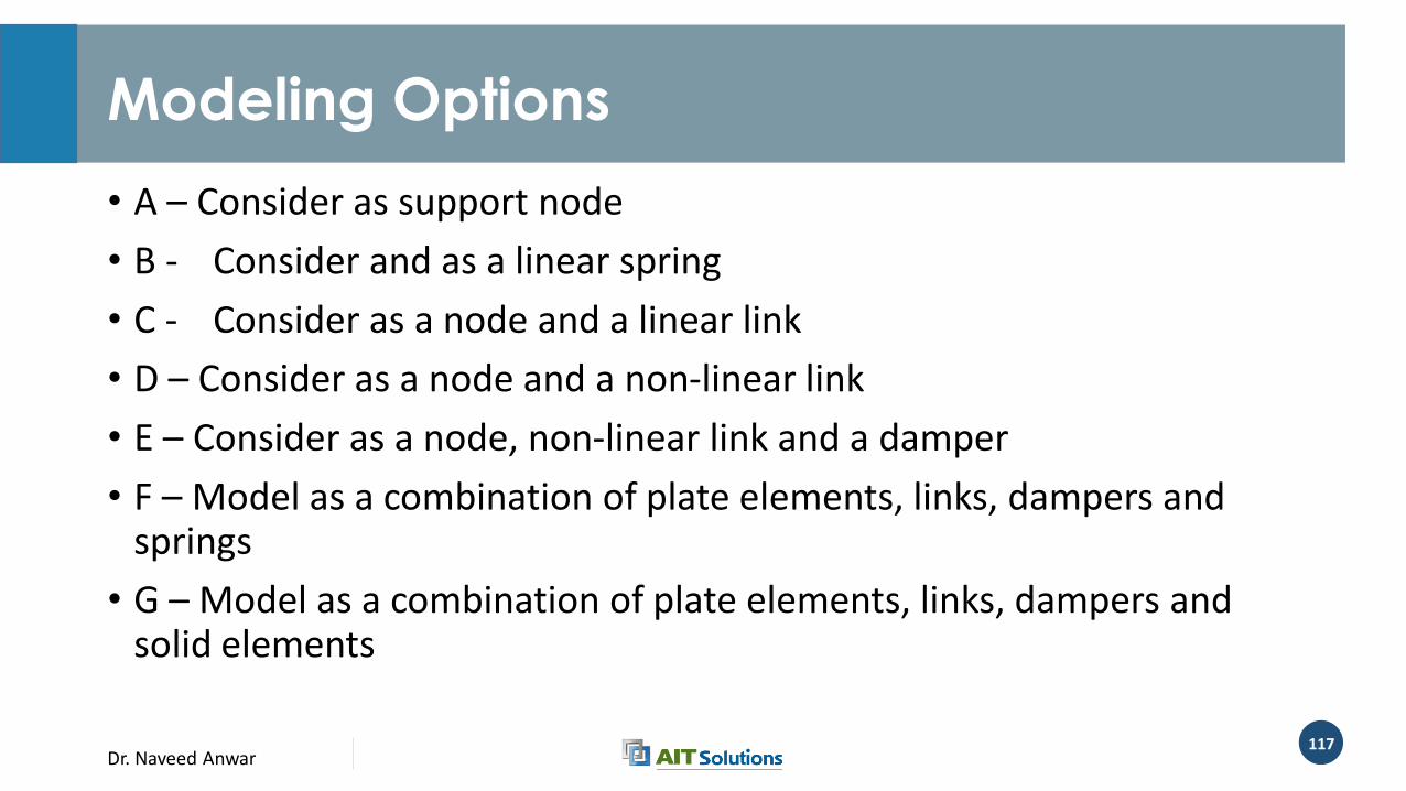
Modeling Options
• A – Consider as support node
• B - Consider and as a linear spring
• C - Consider as a node and a linear link
• D – Consider as a node and a non-linear link
• E – Consider as a node, non-linear link and a damper
• F – Model as a combination of plate elements, links, dampers and springs
• G – Model as a combination of plate elements, links, dampers and solid elements
Dr. Naveed Anwar118
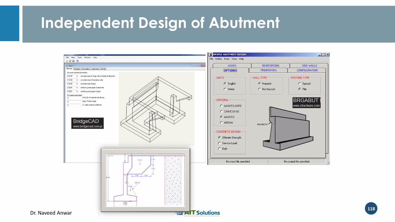
Independent Design of Abutment
Dr. Naveed Anwar119
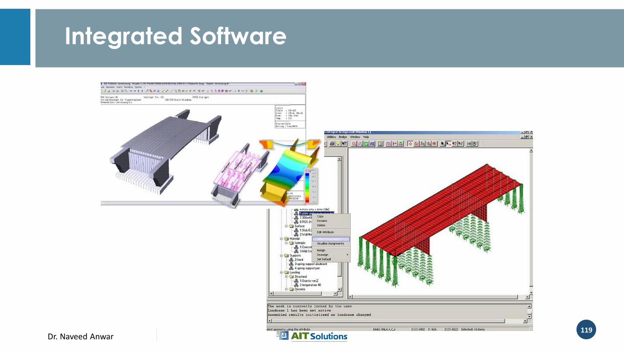
Integrated Software

Dr. Naveed Anwar120
CSI Bridge
Dr. Naveed Anwar121
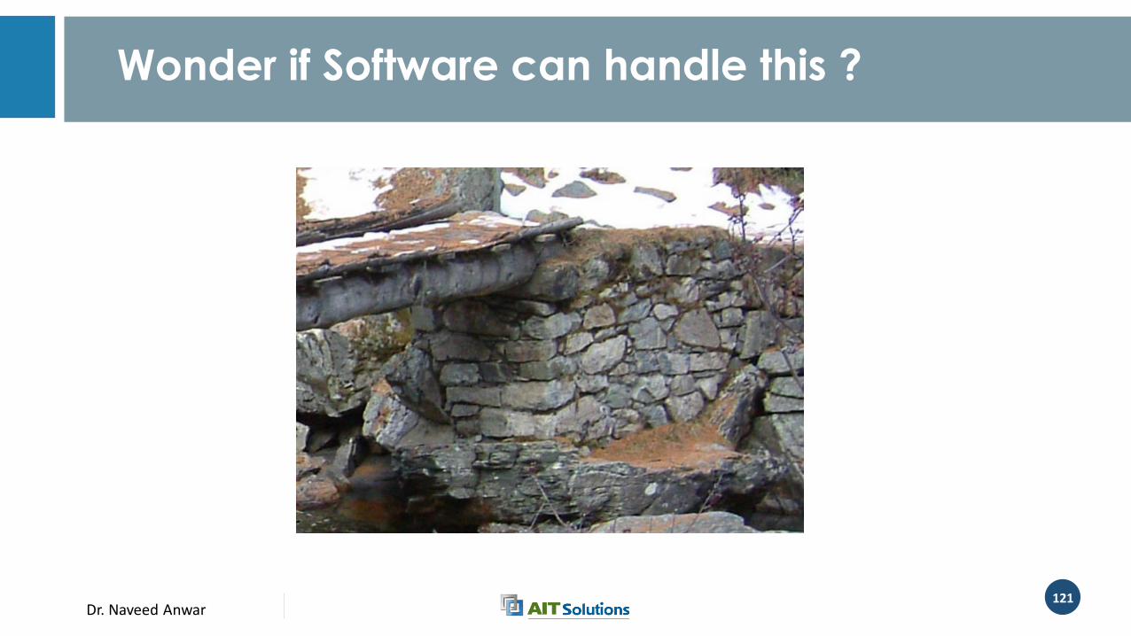
Wonder if Software can handle this ?
Dr. Naveed Anwar122
Modeling Options
• A- As Frame Nodal Support• Consider either as pin or a roller
• If both are considered as roller, then all longitudinal loads should be resisted by the piers
• If roller-pin combination is considered then amount of longitudinal load transferred to pin-end will depend on the stiffness of piers, length of deck, joint between the pier and the deck
• May be appropriate for preliminary analysis, especially when using frame model
• None of the stiffness, movement effects can be considered

Dr. Naveed Anwar123
Modeling Options
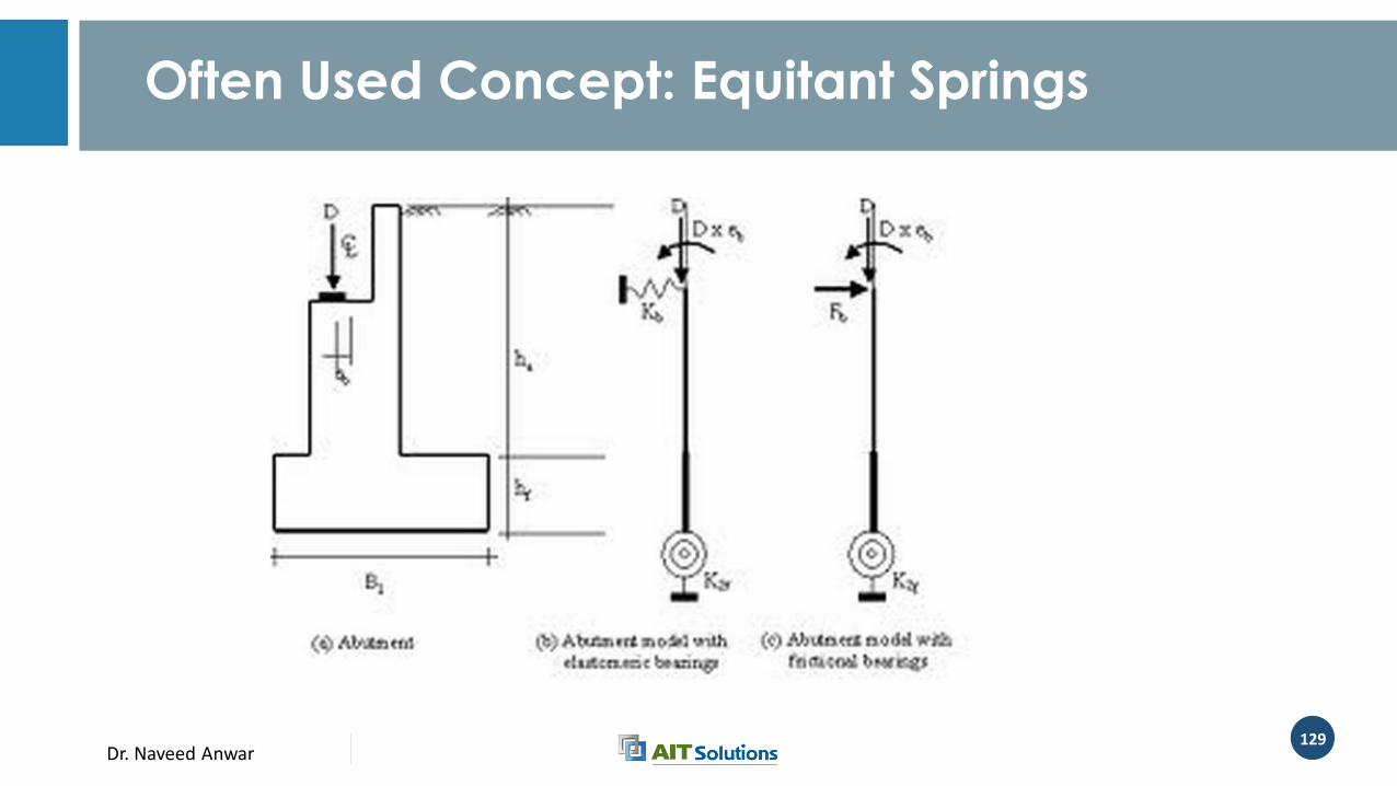
• B – As Frame Spring Support• The sprint support can be use to represent the combined stiffness of the
bearing, the abutment and the passive resistance of the soil
• The spring stiffness can be computed based on the shear modulus of the bearings, lateral modulus of sub-grade reaction of soil and the contact area
• C – As Frame Support Node and Linear Link• The linear link can be used instead of spring support to represent the
combined (lumped) stiffness of all elements involved
Dr. Naveed Anwar124
Modeling Options
• D – As Frame Support Node and a Non-linear link• The non-linear link can model the linear stiffness as spring, as well as capture
non-linear behavior, such as soil separation, expansion joint, restraining block, soil liquefaction etc.
• E – As Frame Support Node, Non-linear Link and Damper• Can model all of the behavior in D, in addition the combined effect of modal
and material damping
• This option is most comprehensive and can be used efficiently in frame models
• Option C, D, E require manual determination of stiffness, nonlinear and damping properties for springs, links and dampers
Dr. Naveed Anwar125
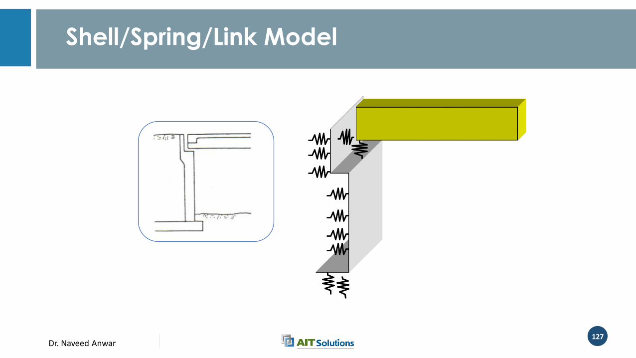
Modeling Options
• F – As Plate Elements, Links, Dampers and Springs• The abutment wall is modeled with plate elements
• The soil is represented as springs
• The connection with the deck is modeled by links and dampers
• G As Plate Elements, Links, Dampers and Solids• The abutment wall is modeled with plate elements
• The soil is modeled by solid elements
• The connection with the deck is modeled by links and dampers
• The connection between soil and wall may be further modeled by non-linear links
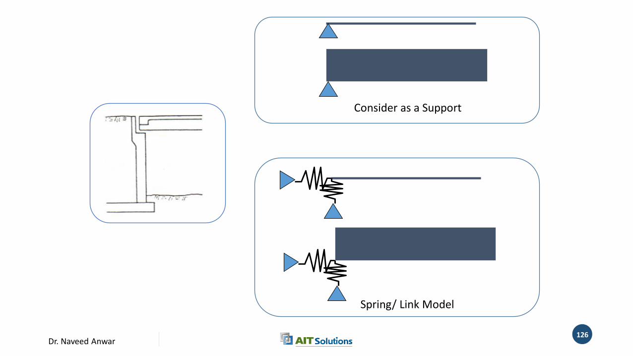
Dr. Naveed Anwar126
Consider as a Support
Spring/ Link Model
Dr. Naveed Anwar127
Shell/Spring/Link Model
Dr. Naveed Anwar128
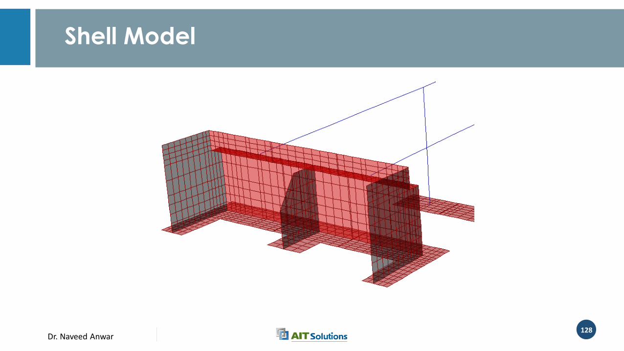
Shell Model
Dr. Naveed Anwar129
Often Used Concept: Equitant Springs
Dr. Naveed Anwar130
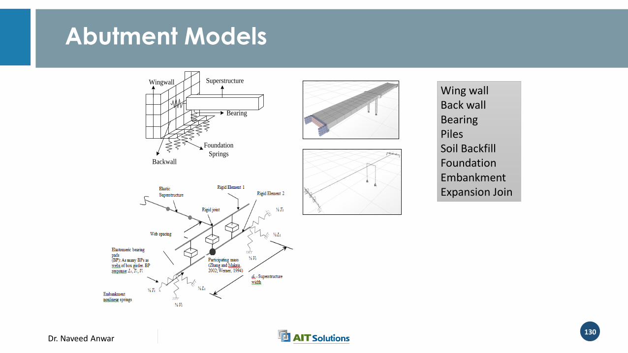
Abutment Models
Backwall
Foundation
Springs
Superstructure
Bearing
Wingwall
Wing wallBack wallBearingPilesSoil BackfillFoundationEmbankmentExpansion Join
Dr. Naveed Anwar131
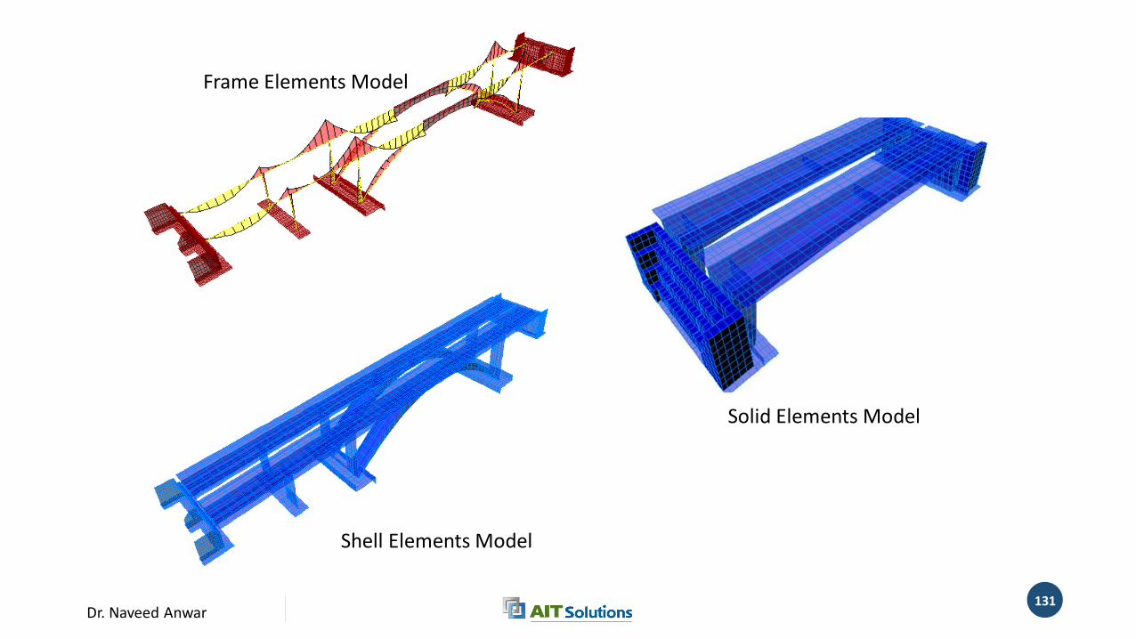
Shell Elements Model
Solid Elements Model
Frame Elements Model
Dr. Naveed Anwar132
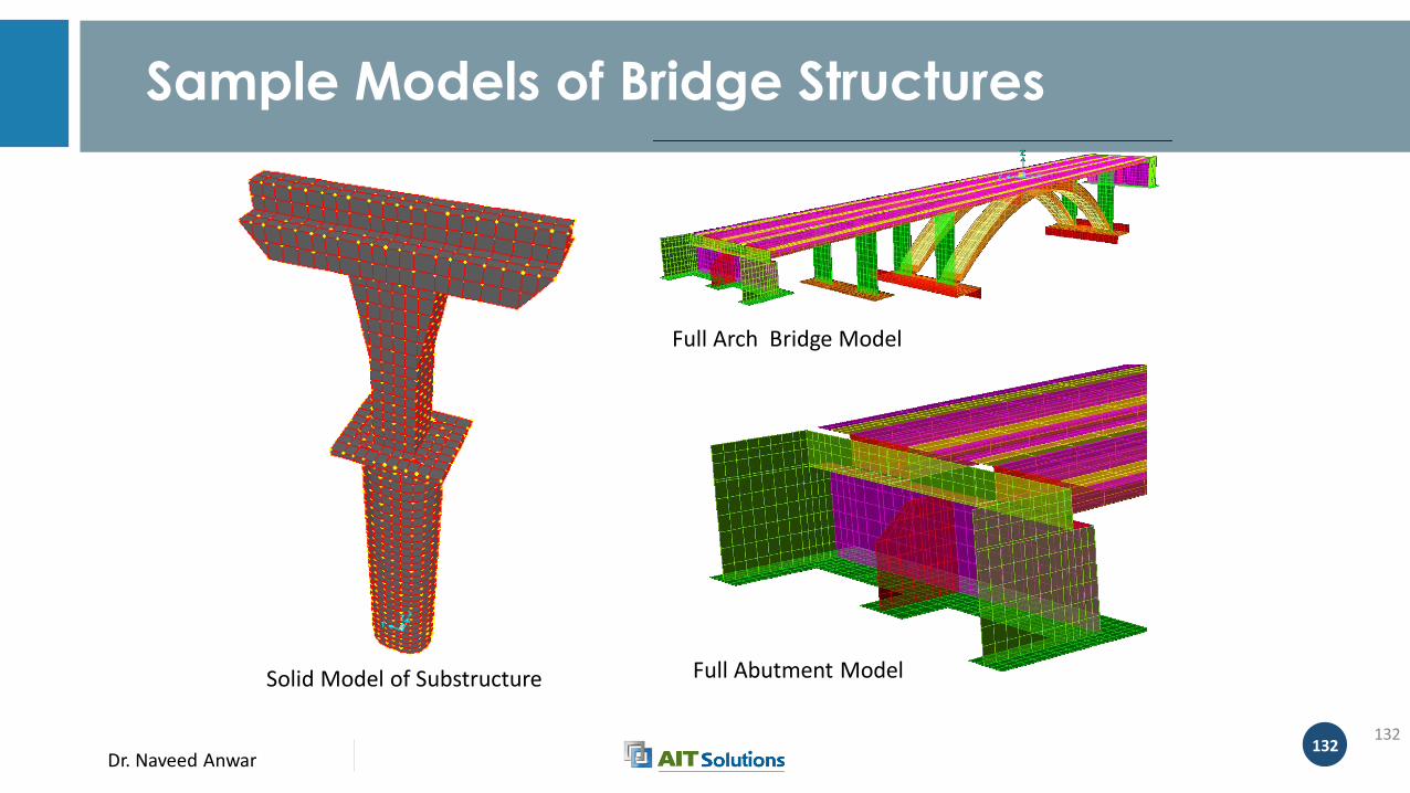
Sample Models of Bridge Structures
132
Solid Model of Substructure Full Abutment Model
Full Arch Bridge Model
Dr. Naveed Anwar
Structural Analysis and Design of Flyover Bridge at Lagos , NigeriaA Case Study
Dr. Naveed Anwar134
Objective and Scope of Work
• Overall review of flyover bridges from design criteria and drawing provided by client.
• Detailed review and design of structure system for 30m and 50m spans at middle of two bridges including pier and foundation.
• Estimation of structure system only for 30m and 50m spans at middle of two bridges including pier and foundation
• Provide final design drawing and calculation report for structure system for 30m and 50m spans at middle of two bridges including pier and foundation
Dr. Naveed Anwar135
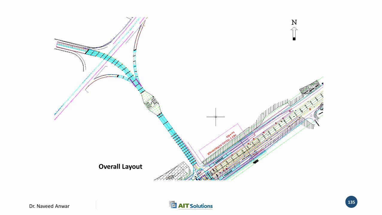
Overall Layout
Overall Layout
Dr. Naveed Anwar136
Dr. Naveed Anwar137
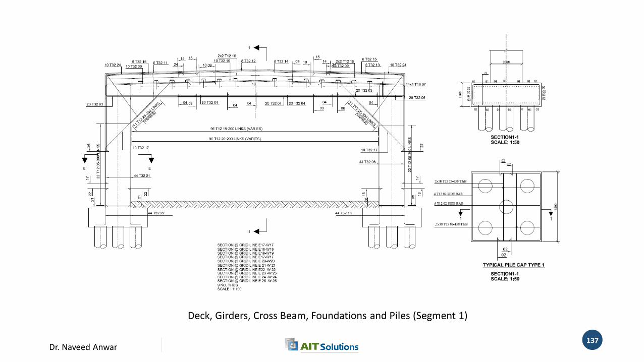
Deck, Girders, Cross Beam, Foundations and Piles (Segment 1)
Dr. Naveed Anwar138
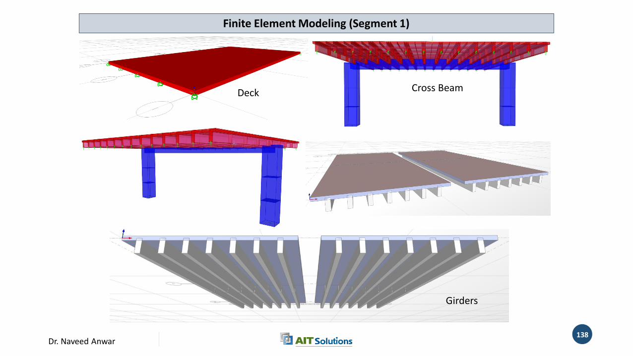
Deck
Girders
Cross Beam
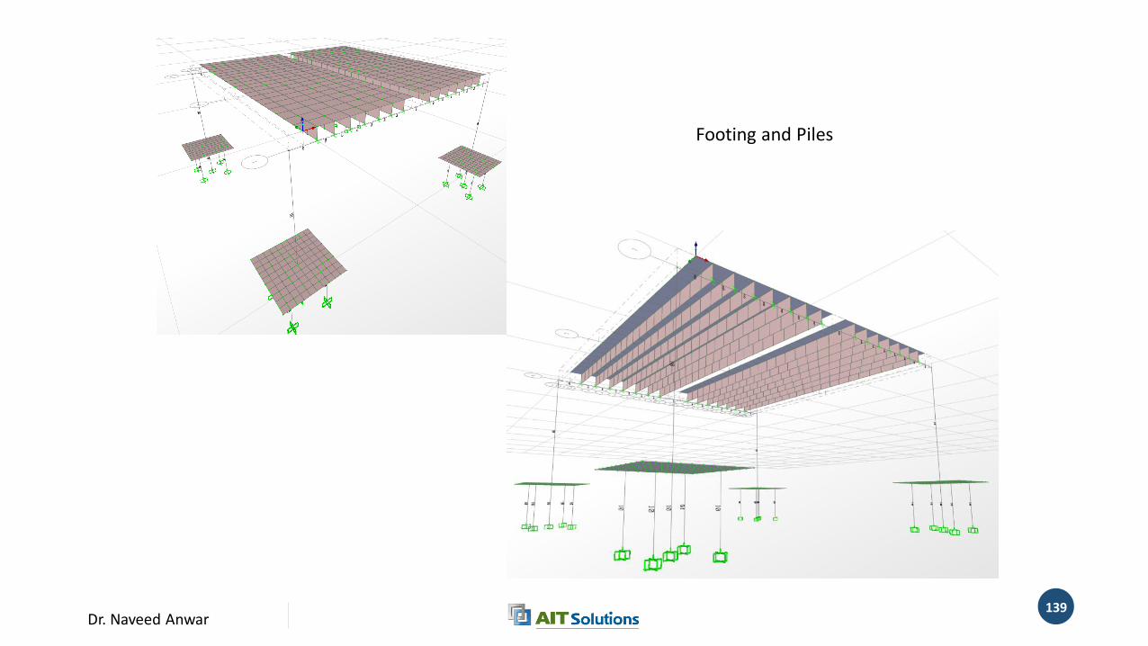
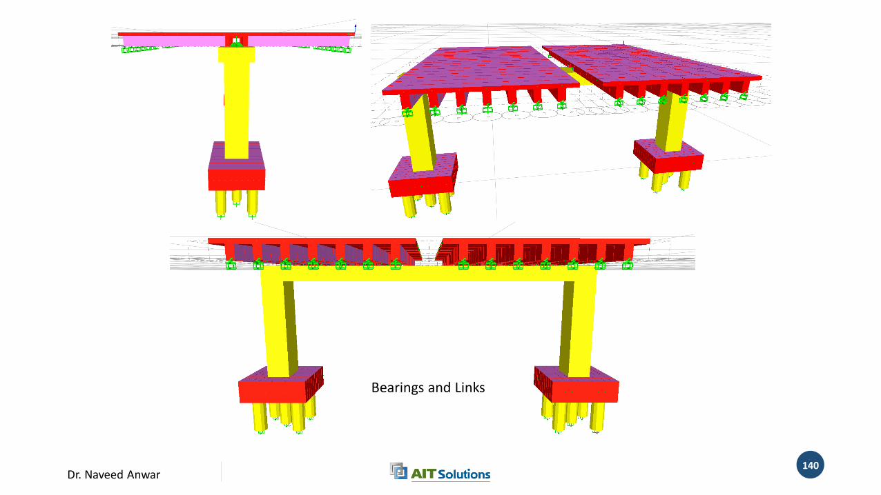
Finite Element Modeling (Segment 1)
Dr. Naveed Anwar139
Footing and Piles
Dr. Naveed Anwar140
Bearings and Links