Embed Size (px)
Citation preview
John M. Tartaglia, Ph.D. Engineering Manager and Senior Metallurgical Engineer Element Materials Technology, Wixom, Michigan
June 4, 2013 American Society of Gas Engineers (ASGE) Technical Conference Las Vegas, NV
Topics in Metallurgy for Gas Engineering
2
Outline • What is Element? • What is Material Science & Engineering? • What is a Steel? • Metallurgy and Types of Stainless Steel • High Temperature Behavior of Steels • Failure Mechanisms • Corrosion Behavior of Materials • Failure Analysis
We are Element, the recognized leader in materials testing, product qualification testing and failure analysis.
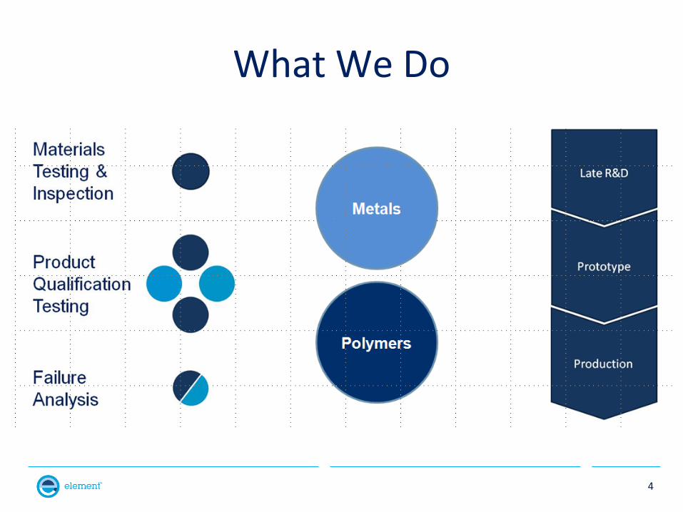
What We Do
4
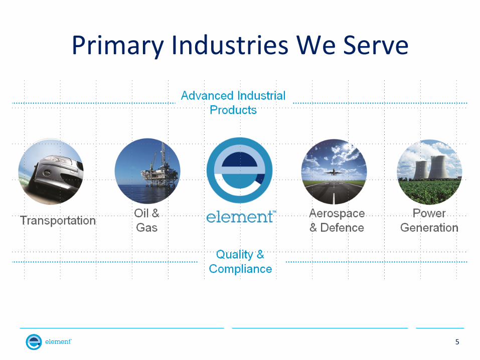
Primary Industries We Serve
5
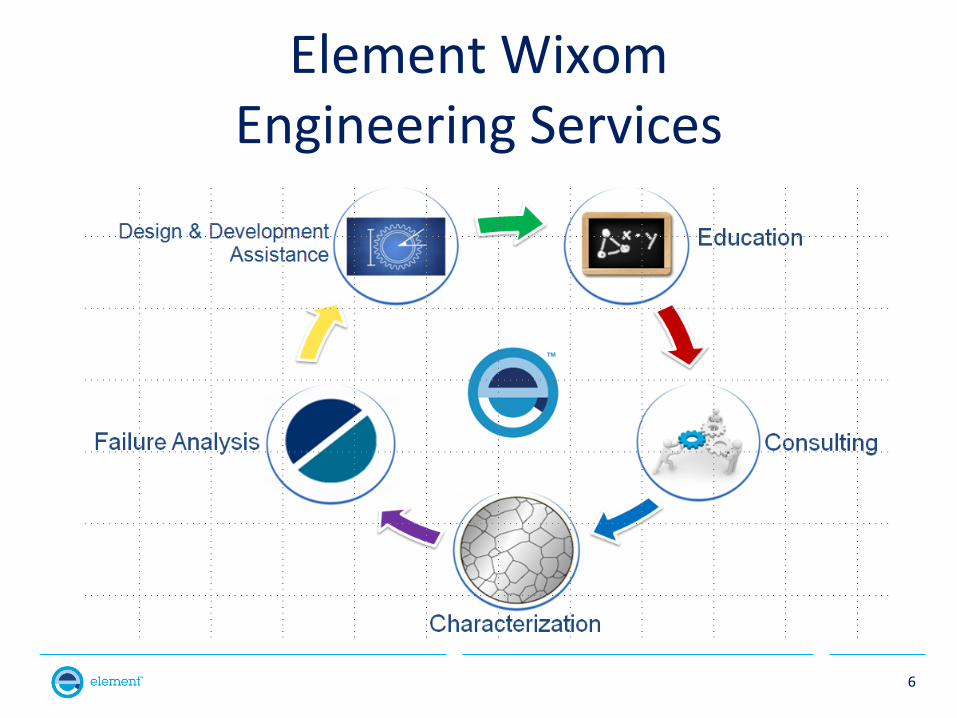
Element Wixom Engineering Services
6
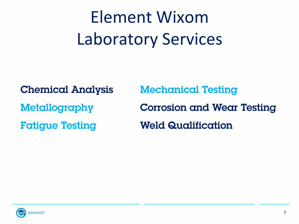
Element Wixom Laboratory Services
7
Chemical Analysis Mechanical Testing
Metallography Corrosion and Wear Testing
Fatigue Testing Weld Qualification
8
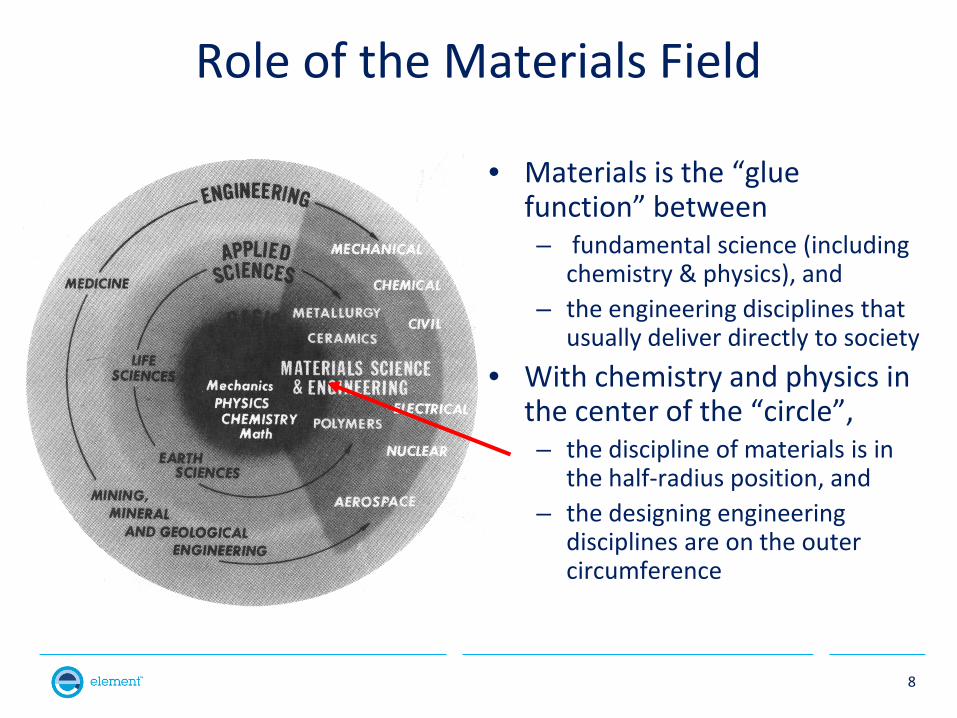
Role of the Materials Field
• Materials is the “glue function” between – fundamental science (including
chemistry & physics), and – the engineering disciplines that
usually deliver directly to society • With chemistry and physics in
the center of the “circle”, – the discipline of materials is in
the half-radius position, and – the designing engineering
disciplines are on the outer circumference
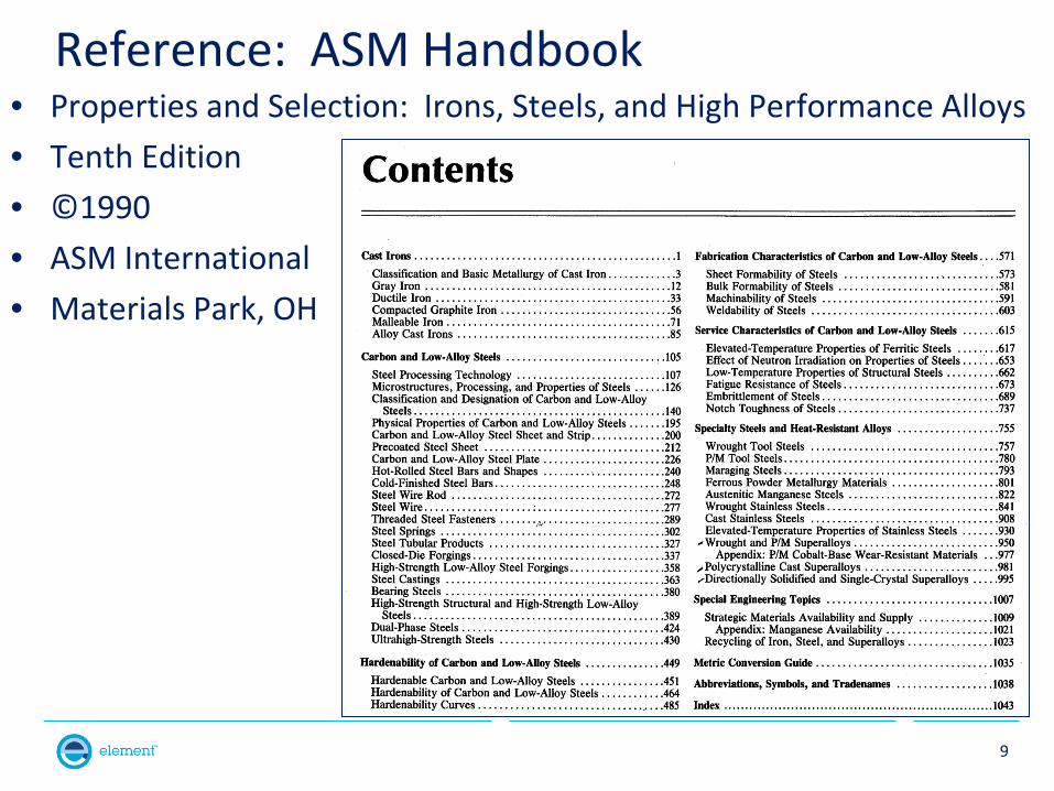
Reference: ASM Handbook • Properties and Selection: Irons, Steels, and High Performance Alloys • Tenth Edition • ©1990 • ASM International • Materials Park, OH
9
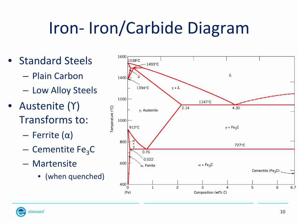
Iron- Iron/Carbide Diagram
• Standard Steels – Plain Carbon – Low Alloy Steels
• Austenite (ϒ) Transforms to: – Ferrite (α) – Cementite Fe3C – Martensite
• (when quenched)
10
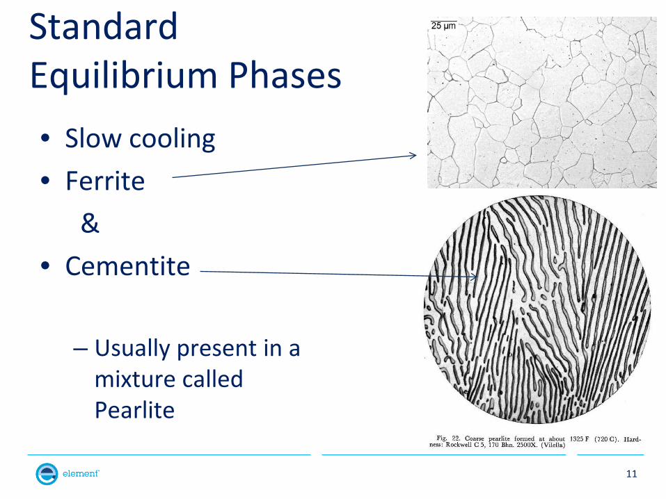
Standard Equilibrium Phases • Slow cooling • Ferrite & • Cementite
– Usually present in a
mixture called Pearlite
11
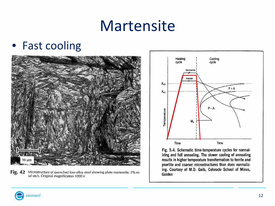
Martensite • Fast cooling
12
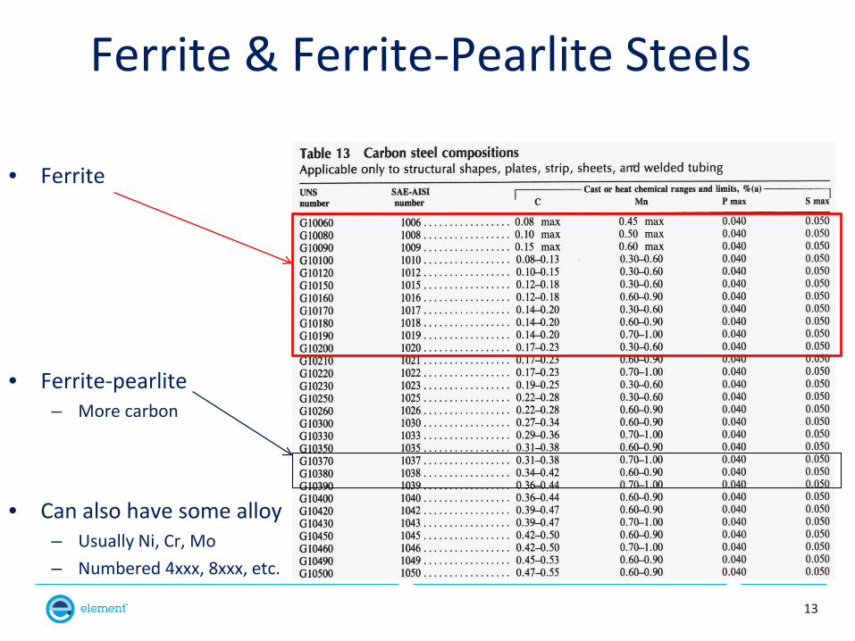
Ferrite & Ferrite-Pearlite Steels
• Ferrite
• Ferrite-pearlite – More carbon
• Can also have some alloy – Usually Ni, Cr, Mo – Numbered 4xxx, 8xxx, etc.
13
Aspects of Stainless Steels
• Phase diagrams • Compositions • Types and naming conventions • Usage • Microstructures
14
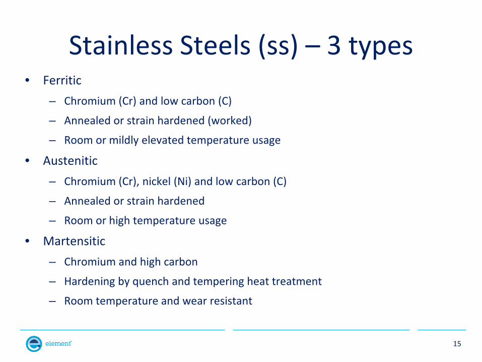
Stainless Steels (ss) – 3 types • Ferritic
– Chromium (Cr) and low carbon (C)
– Annealed or strain hardened (worked)
– Room or mildly elevated temperature usage
• Austenitic – Chromium (Cr), nickel (Ni) and low carbon (C)
– Annealed or strain hardened
– Room or high temperature usage
• Martensitic – Chromium and high carbon
– Hardening by quench and tempering heat treatment
– Room temperature and wear resistant
15
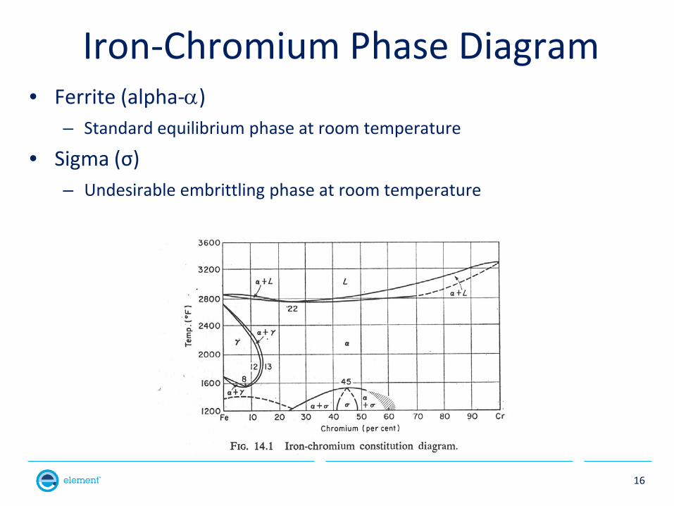
Iron-Chromium Phase Diagram • Ferrite (alpha-α)
– Standard equilibrium phase at room temperature
• Sigma (σ) – Undesirable embrittling phase at room temperature
16
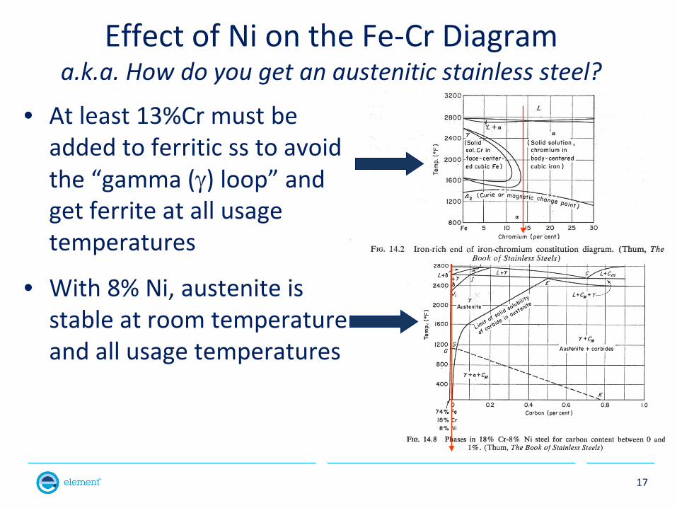
Effect of Ni on the Fe-Cr Diagram a.k.a. How do you get an austenitic stainless steel?
• At least 13%Cr must be added to ferritic ss to avoid the “gamma (γ) loop” and get ferrite at all usage temperatures
• With 8% Ni, austenite is stable at room temperature and all usage temperatures
17
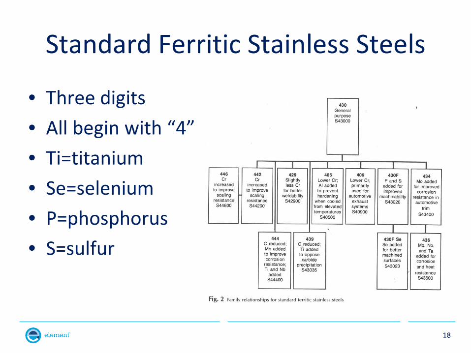
Standard Ferritic Stainless Steels
• Three digits • All begin with “4” • Ti=titanium • Se=selenium • P=phosphorus • S=sulfur
18
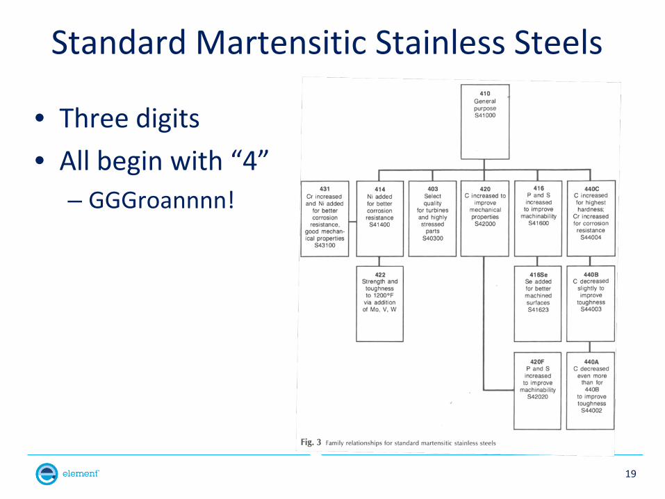
Standard Martensitic Stainless Steels
• Three digits • All begin with “4”
– GGGroannnn!
19
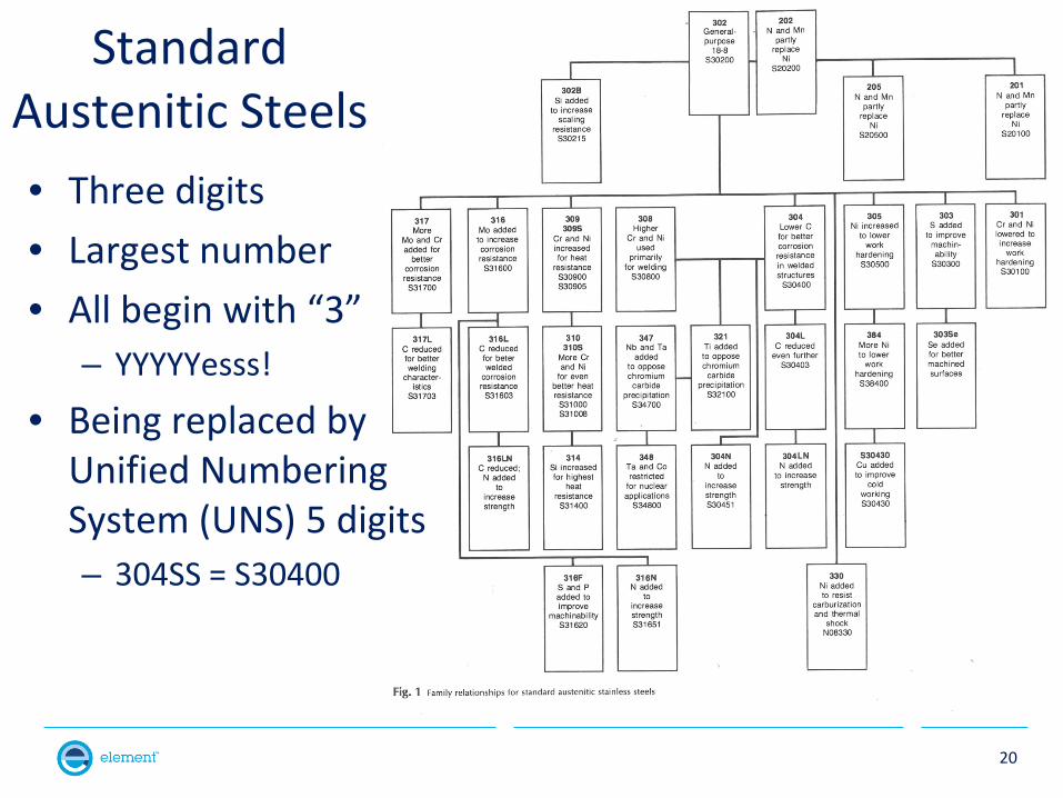
Standard Austenitic Steels • Three digits • Largest number • All begin with “3”
– YYYYYesss!
• Being replaced by Unified Numbering System (UNS) 5 digits – 304SS = S30400
20
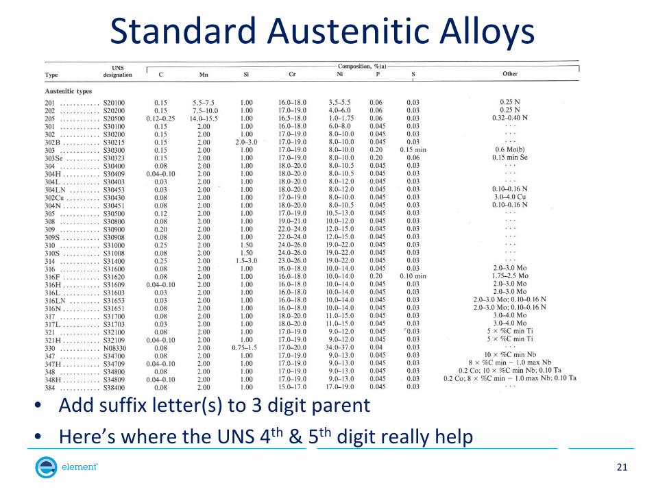
Standard Austenitic Alloys
• Add suffix letter(s) to 3 digit parent • Here’s where the UNS 4th & 5th digit really help
21
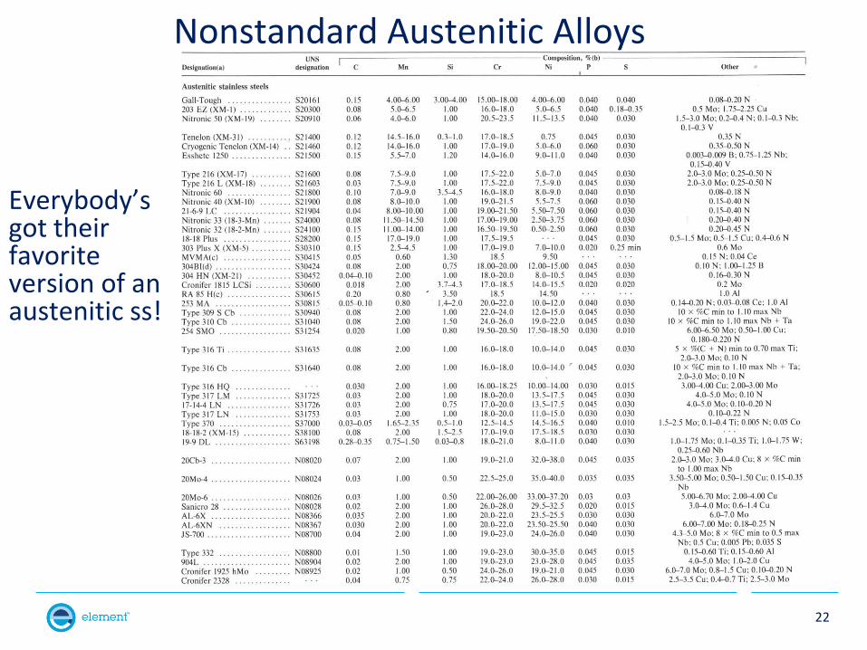
Nonstandard Austenitic Alloys
Everybody’s got their favorite version of an austenitic ss!
22
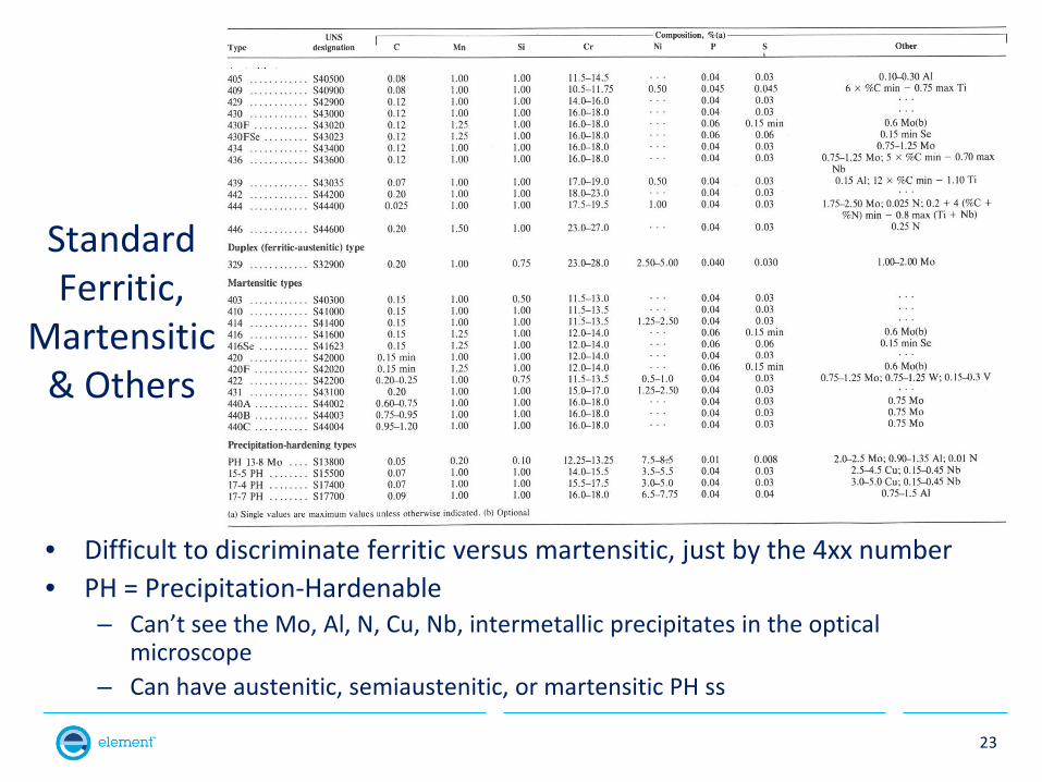
Standard Ferritic,
Martensitic & Others
• Difficult to discriminate ferritic versus martensitic, just by the 4xx number • PH = Precipitation-Hardenable
– Can’t see the Mo, Al, N, Cu, Nb, intermetallic precipitates in the optical microscope
– Can have austenitic, semiaustenitic, or martensitic PH ss
23
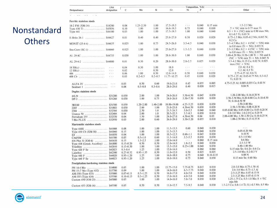
Nonstandard Others
24
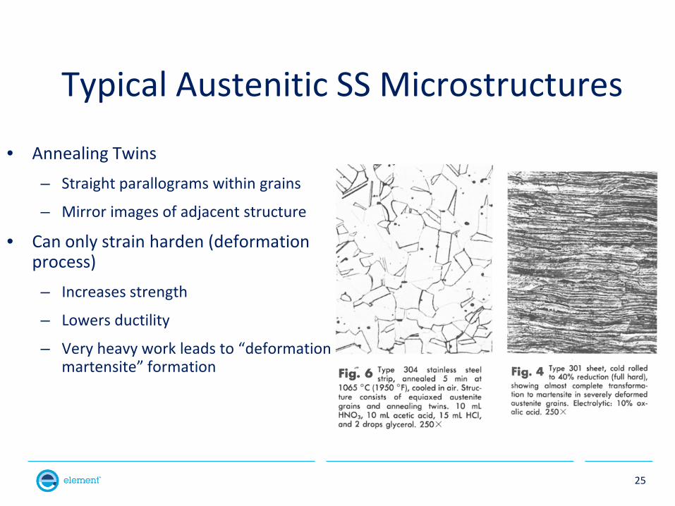
Typical Austenitic SS Microstructures
• Annealing Twins – Straight parallograms within grains
– Mirror images of adjacent structure
• Can only strain harden (deformation process) – Increases strength
– Lowers ductility
– Very heavy work leads to “deformation martensite” formation
25
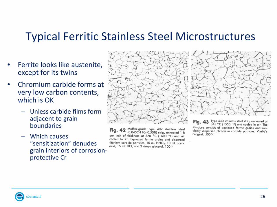
Typical Ferritic Stainless Steel Microstructures
• Ferrite looks like austenite, except for its twins
• Chromium carbide forms at very low carbon contents, which is OK – Unless carbide films form
adjacent to grain boundaries
– Which causes “sensitization” denudes grain interiors of corrosion-protective Cr
26
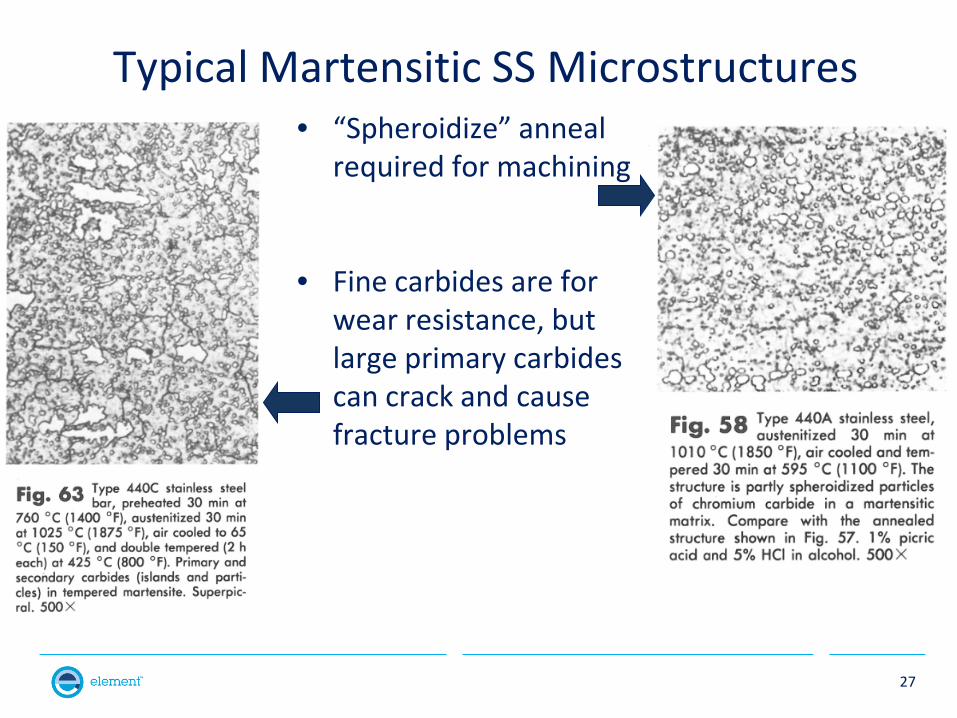
Typical Martensitic SS Microstructures • “Spheroidize” anneal
required for machining
• Fine carbides are for wear resistance, but large primary carbides can crack and cause fracture problems
27
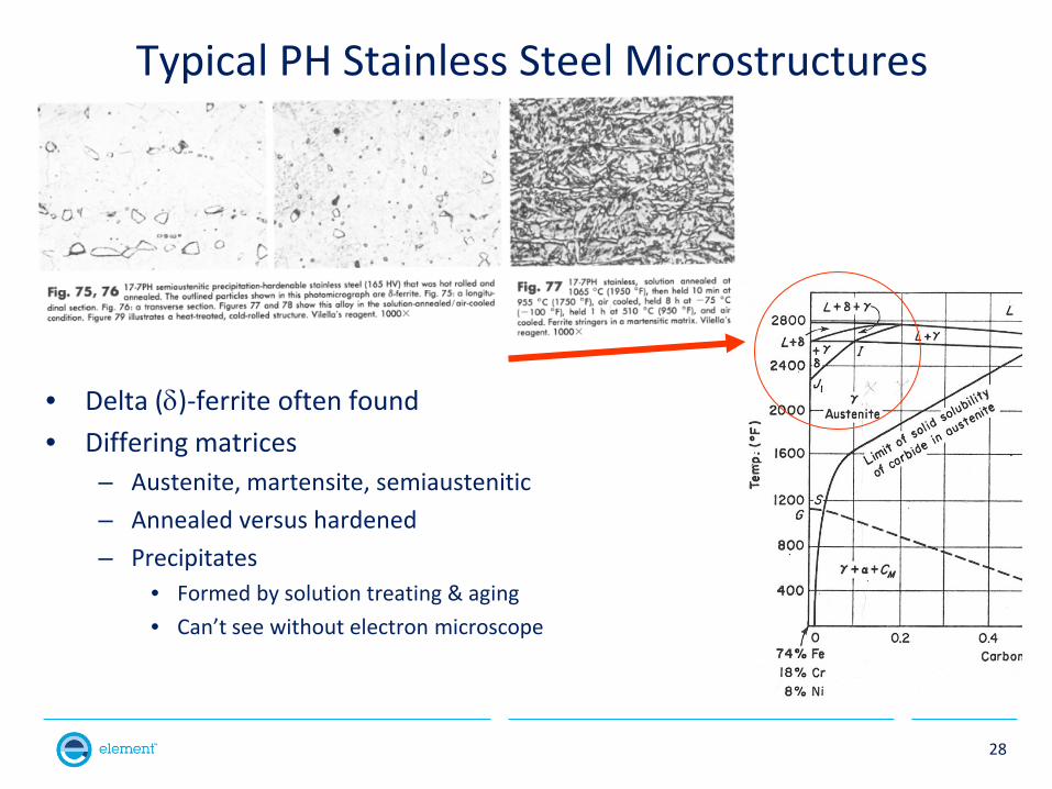
Typical PH Stainless Steel Microstructures
• Delta (δ)-ferrite often found • Differing matrices
– Austenite, martensite, semiaustenitic – Annealed versus hardened – Precipitates
• Formed by solution treating & aging • Can’t see without electron microscope
28
High Temperature Effects
• Properties of materials with increasing temperature
• Comparison of carbon and alloy steels to stainless steels
• Effect of Thermal Expansion Mismatch
29
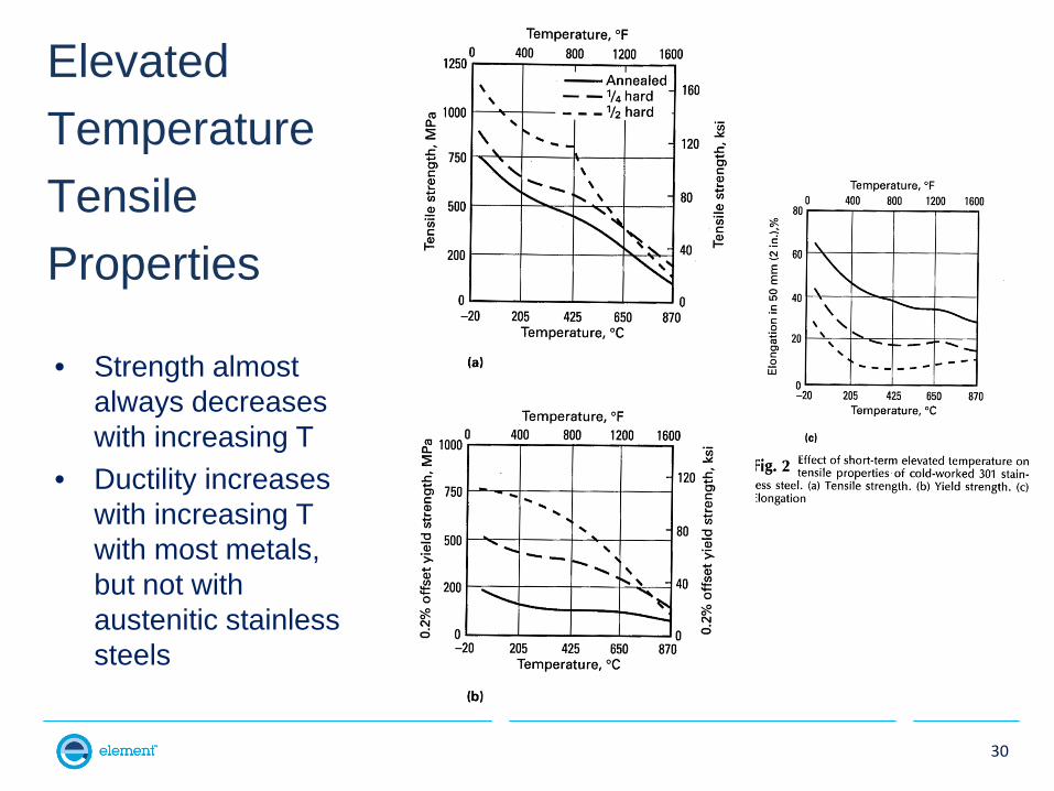
Elevated Temperature Tensile Properties
• Strength almost always decreases with increasing T
• Ductility increases with increasing T with most metals, but not with austenitic stainless steels
30
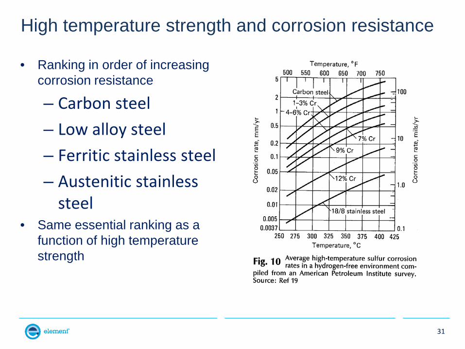
High temperature strength and corrosion resistance
• Ranking in order of increasing corrosion resistance
– Carbon steel – Low alloy steel – Ferritic stainless steel – Austenitic stainless
steel • Same essential ranking as a
function of high temperature strength
31
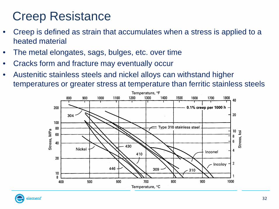
Creep Resistance • Creep is defined as strain that accumulates when a stress is applied to a
heated material • The metal elongates, sags, bulges, etc. over time • Cracks form and fracture may eventually occur • Austenitic stainless steels and nickel alloys can withstand higher
temperatures or greater stress at temperature than ferritic stainless steels
32
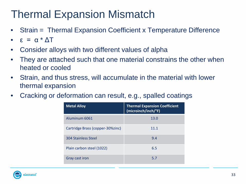
Thermal Expansion Mismatch • Strain = Thermal Expansion Coefficient x Temperature Difference • ε = α * ΔT • Consider alloys with two different values of alpha • They are attached such that one material constrains the other when
heated or cooled • Strain, and thus stress, will accumulate in the material with lower
thermal expansion • Cracking or deformation can result, e.g., spalled coatings
33
Metal Alloy Thermal Expansion Coefficient (microinch/inch/°F)
Aluminum 6061 13.0
Cartridge Brass (copper-30%zinc) 11.1
304 Stainless Steel 9.4
Plain carbon steel (1022) 6.5
Gray cast iron 5.7
34
What is a Failure
• ASM’s General Definition of a Failure: – “Failure” is a general term used to imply that a part in
service 1)Has become completely inoperable, 2)Is still operable, but is incapable of satisfactorily
performing its intended function, or 3)Has deteriorated seriously, to the point that it has
become unreliable or unsafe to use.
35
Design Failure Causes or Contributions
• Design, manufacturing, and materials can all cause failures, either singly or in combination
• Choosing the wrong material is a design cause for failure • Design failures are caused by not considering or inadequately handling the
component’s: – Loading – Constraint – Service environment (for temperature, corrosivity, or wind) – Actual usage conditions – Cyclic loading – Deleterious mechanical interaction with nearby components (abrasion
due to dissimilar hardness) – Deleterious corrosion interaction with nearby components (galvanic
interaction of two elements on different sides of the periodic table)
36
Failure Causes or Contributions from Manufacturing
• Defects produced by component manufacturing including surface roughness, nicks, sharp corners, poor tolerancing, dimensional agreement (fit), improper property specification, etc.
• Insufficient robustness
– Low process repeatability and/or reproducibility, or – Unrepeatable or nonreproducible material response to a robust process.
• Insufficient quality assurance testing of production components due to
– High cost – Inadequate available time, or – Almost as often, poorly specified test procedure or pass/fail criteria
37
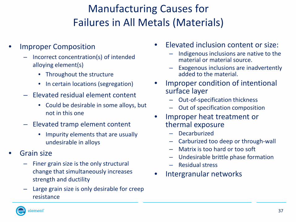
Manufacturing Causes for Failures in All Metals (Materials)
• Improper Composition – Incorrect concentration(s) of intended
alloying element(s) • Throughout the structure • In certain locations (segregation)
– Elevated residual element content • Could be desirable in some alloys, but
not in this one
– Elevated tramp element content • Impurity elements that are usually
undesirable in alloys
• Grain size – Finer grain size is the only structural
change that simultaneously increases strength and ductility
– Large grain size is only desirable for creep resistance
• Elevated inclusion content or size: – Indigenous inclusions are native to the
material or material source. – Exogenous inclusions are inadvertently
added to the material. • Improper condition of intentional
surface layer – Out-of-specification thickness – Out of specification composition
• Improper heat treatment or thermal exposure
– Decarburized – Carburized too deep or through-wall – Matrix is too hard or too soft – Undesirable brittle phase formation – Residual stress
• Intergranular networks
38
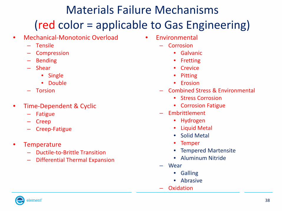
Materials Failure Mechanisms (red color = applicable to Gas Engineering)
• Mechanical-Monotonic Overload – Tensile – Compression – Bending – Shear
• Single • Double
– Torsion
• Time-Dependent & Cyclic – Fatigue – Creep – Creep-Fatigue
• Temperature
– Ductile-to-Brittle Transition – Differential Thermal Expansion
• Environmental – Corrosion
• Galvanic • Fretting • Crevice • Pitting • Erosion
– Combined Stress & Environmental • Stress Corrosion • Corrosion Fatigue
– Embrittlement • Hydrogen • Liquid Metal • Solid Metal • Temper • Tempered Martensite • Aluminum Nitride
– Wear • Galling • Abrasive
– Oxidation
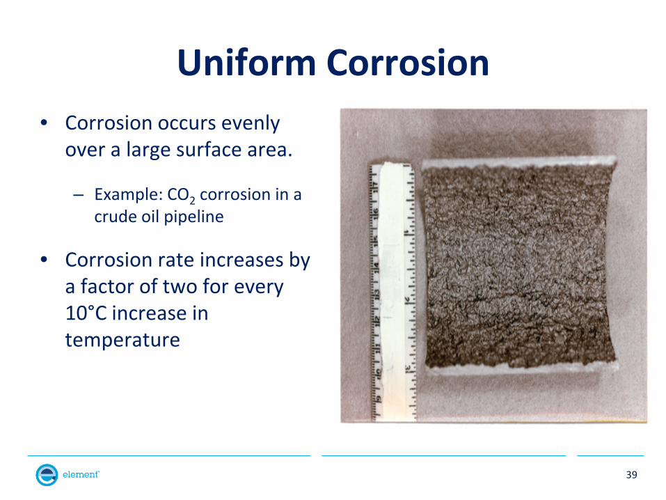
Uniform Corrosion • Corrosion occurs evenly
over a large surface area.
– Example: CO2 corrosion in a crude oil pipeline
• Corrosion rate increases by a factor of two for every 10°C increase in temperature
39
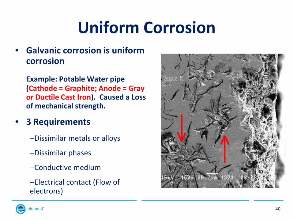
Uniform Corrosion • Galvanic corrosion is uniform
corrosion
Example: Potable Water pipe (Cathode = Graphite; Anode = Gray or Ductile Cast Iron). Caused a Loss of mechanical strength.
• 3 Requirements
–Dissimilar metals or alloys
–Dissimilar phases
–Conductive medium
–Electrical contact (Flow of electrons)
40
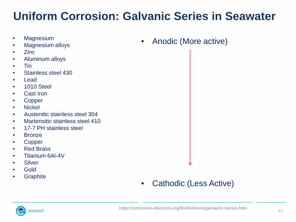
http://corrosion-doctors.org/Definitions/galvanic-series.htm
Uniform Corrosion: Galvanic Series in Seawater • Magnesium • Magnesium alloys • Zinc • Aluminum alloys • Tin • Stainless steel 430 • Lead • 1010 Steel • Cast Iron • Copper • Nickel • Austenitic stainless steel 304 • Martensitic stainless steel 410 • 17-7 PH stainless steel • Bronze • Copper • Red Brass • Titanium 6Al-4V • Silver • Gold • Graphite
41
• Anodic (More active)
• Cathodic (Less Active)
Uniform Corrosion
• Galvanic Series Guidelines
– Distance apart in the series
• Closer means Less Corrosion
– Small area (Cathode/Anode) ratio
• Small CAR is desirable
– Electrolyte is important
• Order of the cathodic versus anodic materials may change in different electrolytes
42
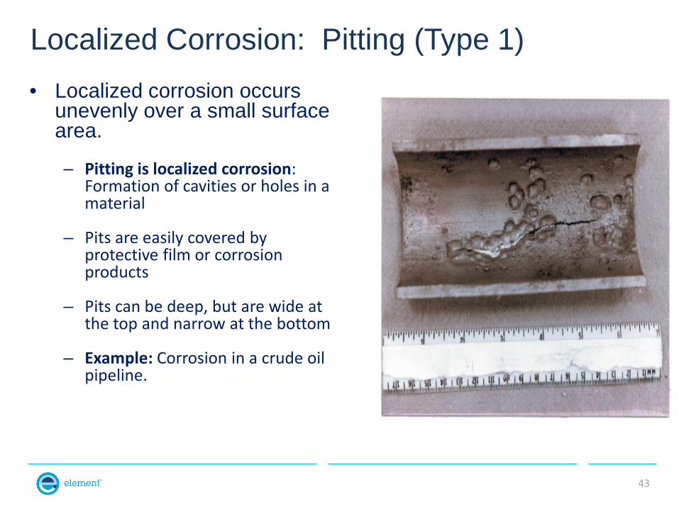
Localized Corrosion: Pitting (Type 1) • Localized corrosion occurs
unevenly over a small surface area.
– Pitting is localized corrosion: Formation of cavities or holes in a material
– Pits are easily covered by protective film or corrosion products
– Pits can be deep, but are wide at the top and narrow at the bottom
– Example: Corrosion in a crude oil pipeline.
43
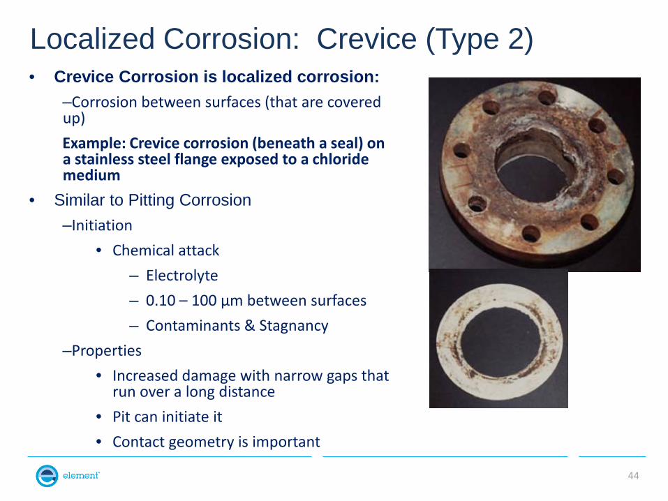
Localized Corrosion: Crevice (Type 2) • Crevice Corrosion is localized corrosion:
–Corrosion between surfaces (that are covered up) Example: Crevice corrosion (beneath a seal) on a stainless steel flange exposed to a chloride medium
• Similar to Pitting Corrosion –Initiation
• Chemical attack – Electrolyte – 0.10 – 100 µm between surfaces – Contaminants & Stagnancy
–Properties • Increased damage with narrow gaps that
run over a long distance • Pit can initiate it • Contact geometry is important
44
45
Environmentally-Induced Cracking
• Requires a combination of • Stress (applied or residual)
• Corrosive medium, and
• Susceptible material/condition
• Hydrogen Damage
• Stress Corrosion Cracking
• Liquid Metal Embrittlement
46
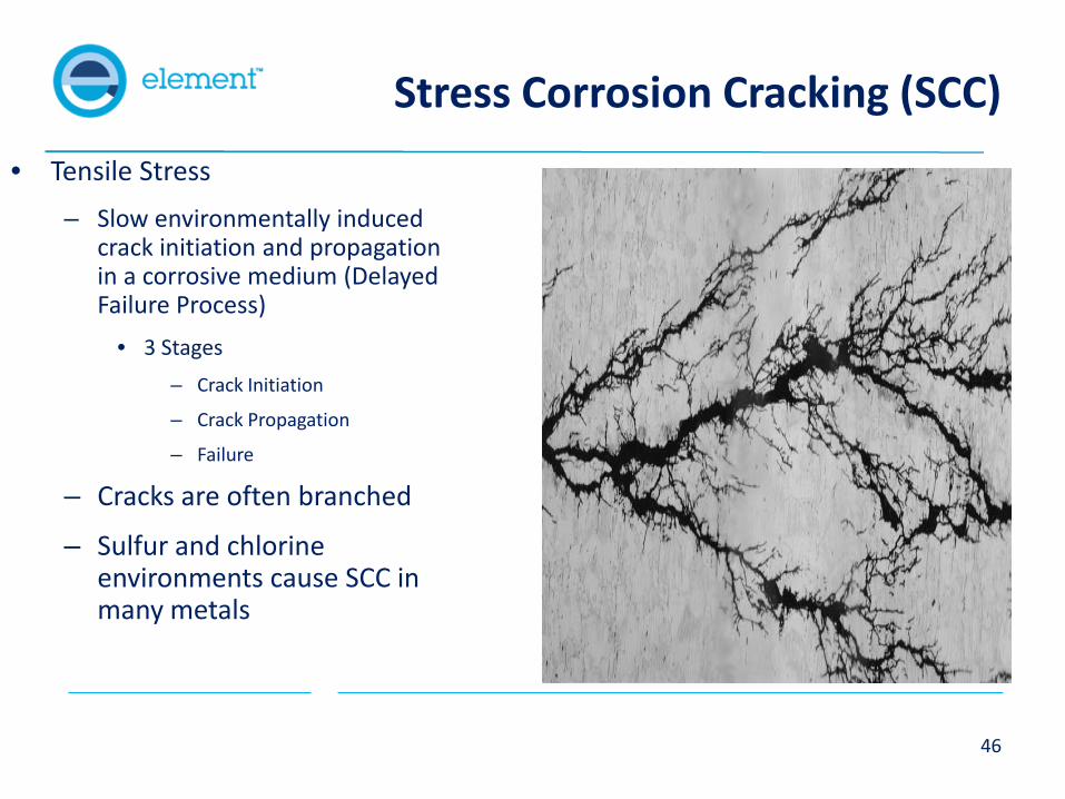
Stress Corrosion Cracking (SCC) • Tensile Stress
– Slow environmentally induced crack initiation and propagation in a corrosive medium (Delayed Failure Process)
• 3 Stages – Crack Initiation
– Crack Propagation
– Failure
– Cracks are often branched
– Sulfur and chlorine environments cause SCC in many metals
47
Questions answered by “Fracture Analysis”
• The questions are: – How did ____ happen?
• Correct substitutions for the underline are….. – the fracture – the crack
– “What does the fracture or crack look like?” a.k.a.
• What loading states were present? (Bending, tension, fatigue) • What was the fracture “morphology”? (Dimples, striations, cleavage) • Where did the crack “initiate”? (Fillet radius, sharp corner) • Can you see any feature that initiated the crack? (Nah, not always….better
question is “Can you see, and then at least characterize, any feature that is present where the crack initiated?”)
• How did the crack “propagate” (increase in length or branch through the material)?
48
Questions answered by “Failure Analysis”
• Note that some failures don’t include fractures, although most failures do include fractures. When the failure does include a fracture, the failure analysis also answers the previously stated questions answered by fracture analysis.
• Additional correct questions answered by a failure analysis are:
– What caused the failure? – When did the failure happen? (Not in time sense, but in process
sequence.) – Is the failed component different than the rest of the components in
inventory or service? – Who is responsible for the failure?
49
Typical Stages Of A Failure Analysis
• Gather Information • Nondestructive Testing • Destructive Testing • Reporting
50
Get Part Information
• Identification information • Material composition • Applicable specifications and/or drawings • Heat treatment • Mechanical properties • Physical characteristics • Manufacturing process steps • Relationship to other components when in use
51
Get Part History • Service duration and storage
• Operating Environment – elevated temperature or corrosive exposure
• Types of loading - tension, compressive, torsion, cyclic, impact
• Anomalous service conditions
• Failure of adjacent components
• Repair and rework history
• Frequency of occurrence of other failures
52
Sampling and Testing Plan
• Collect and preserve information and physical Items
• Determine the scope of investigation
• Define timing for completion
• Plan sequence of examinations for the failed item – Other examples (“exemplars”) available for study?
• Prepare a test protocol
53
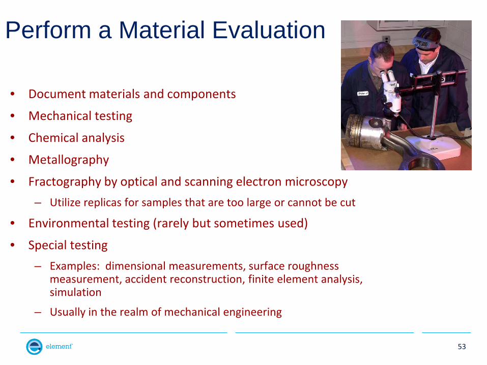
Perform a Material Evaluation
• Document materials and components
• Mechanical testing
• Chemical analysis
• Metallography
• Fractography by optical and scanning electron microscopy – Utilize replicas for samples that are too large or cannot be cut
• Environmental testing (rarely but sometimes used)
• Special testing – Examples: dimensional measurements, surface roughness
measurement, accident reconstruction, finite element analysis, simulation
– Usually in the realm of mechanical engineering
54
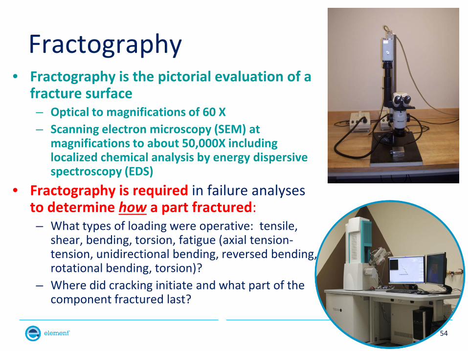
Fractography • Fractography is the pictorial evaluation of a
fracture surface – Optical to magnifications of 60 X – Scanning electron microscopy (SEM) at
magnifications to about 50,000X including localized chemical analysis by energy dispersive spectroscopy (EDS)
• Fractography is required in failure analyses to determine how a part fractured: – What types of loading were operative: tensile,
shear, bending, torsion, fatigue (axial tension-tension, unidirectional bending, reversed bending, rotational bending, torsion)?
– Where did cracking initiate and what part of the component fractured last?
55
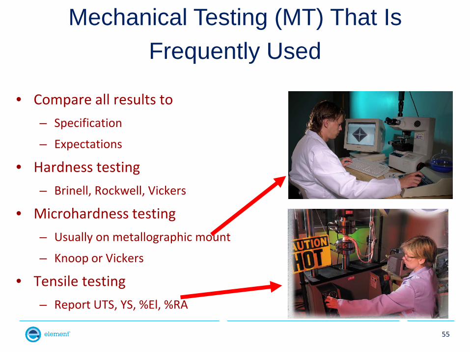
Mechanical Testing (MT) That Is Frequently Used
• Compare all results to – Specification
– Expectations
• Hardness testing – Brinell, Rockwell, Vickers
• Microhardness testing – Usually on metallographic mount
– Knoop or Vickers
• Tensile testing – Report UTS, YS, %El, %RA
56
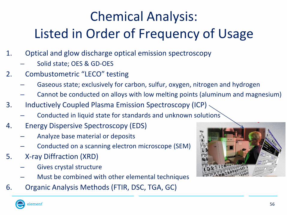
Chemical Analysis: Listed in Order of Frequency of Usage
1. Optical and glow discharge optical emission spectroscopy – Solid state; OES & GD-OES
2. Combustometric “LECO” testing – Gaseous state; exclusively for carbon, sulfur, oxygen, nitrogen and hydrogen – Cannot be conducted on alloys with low melting points (aluminum and magnesium)
3. Inductively Coupled Plasma Emission Spectroscopy (ICP) – Conducted in liquid state for standards and unknown solutions
4. Energy Dispersive Spectroscopy (EDS) – Analyze base material or deposits – Conducted on a scanning electron microscope (SEM)
5. X-ray Diffraction (XRD) – Gives crystal structure – Must be combined with other elemental techniques
6. Organic Analysis Methods (FTIR, DSC, TGA, GC)
57
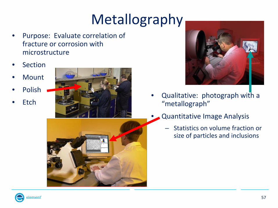
Metallography • Purpose: Evaluate correlation of
fracture or corrosion with microstructure
• Section
• Mount
• Polish
• Etch • Qualitative: photograph with a
“metallograph”
• Quantitative Image Analysis – Statistics on volume fraction or
size of particles and inclusions
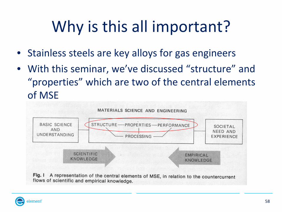
Why is this all important? • Stainless steels are key alloys for gas engineers • With this seminar, we’ve discussed “structure” and
“properties” which are two of the central elements of MSE
58
59
• Dr. John M. Tartaglia Engineering Manager
Main Tel: 248-960-4900 Direct Tel: 248-560-4018 Fax: 248-960-5973 E-mail: [email protected] 51229 Century Court Wixom, MI 48393 element.com
Contact