Embed Size (px)
Citation preview
TOPMACS 1/53
internal report: <partner acronym., <month>, <year>
TOPMACS consortium is the sole owner of this document. It cannot be copied or given to third parties without permission
Number: TST4-CT-2005-012471
Acronym: TOPMACS
Title: Thermally Operated Mobile Air Conditioning Systems
Final Report
Publishable Version
Report Version: 01
Report Preparation Date:
Classification: Publishable
Contract Start Date: March 1, 2005
Duration:
Project funded by the EU
Sixth Framework Program
Contract N°012471

TOPMACS 2/53
internal report: <partner acronym., <month>, <year>
TOPMACS consortium is the sole owner of this document. It cannot be copied or given to third parties without permission
Document History
Version File Name Author(s) Revised Approved Date
01 D.Magnetto
TOPMACS 3/53
internal report: <partner acronym., <month>, <year>
TOPMACS consortium is the sole owner of this document. It cannot be copied or given to third parties without permission
Table of Contents
Document History
Table of Contents
1. Introduction
2. The TOPMACS A/C Key Features
2.1 Main Features 2.2 Key Results
3. The Truck Demonstrator with the Thermally Operated A/C System
3.1 The adsorption chiller: design and manufacturing
3.1.1 System constrains and requirements
3.1.2 Design and realization of the adsorptive prototype
3.2 Testing by the laboratory test bench 3.3 On board integration 3.4 Experimental results 3.5 CONCLUSIONS
4. The passenger car with the A/C System working on the engine coolant waste heat
4.1 Adsorption cooling system development
4.1.1 Overall system lay-out
4.1.2 Prototype adsorption cooling system
4.2 Laboratory measurements and results
4.2.1 Laboratory performance overview
4.3 On-board installation and tests
4.3.1 3.1 Preliminary tests
4.3.2 3.2 Test in the climatic roller bench room
4.4 Comparison of test results on the bench and on the car. 4.5 Conclusions
5. Towards more industrialized components
5.1 Design of a compact sorption cooling system
5.1.1 Sorption cooling reactor design
5.1.2 Refrigerant vapor distribution system design
5.1.3 Liquid distribution system design
TOPMACS 4/53
internal report: <partner acronym., <month>, <year>
TOPMACS consortium is the sole owner of this document. It cannot be copied or given to third parties without permission
5.1.4 Reactor assembly
5.1.5 Vehicle integration
5.1.6 Estimation of cooling power
6. Activated Carbon-Ammonia cooling system bench prototype
7. Mechanically driven metal hydride system
7.1 Working principle 7.2 System layout 7.3 Reaction bed manufacturing and assembling of test bench 7.4 Experimental results 7.5 Analysis of vacuum pump performance
8. Final Conclusions
TOPMACS 5/53
internal report: <partner acronym., <month>, <year>
TOPMACS consortium is the sole owner of this document. It cannot be copied or given to third parties without permission
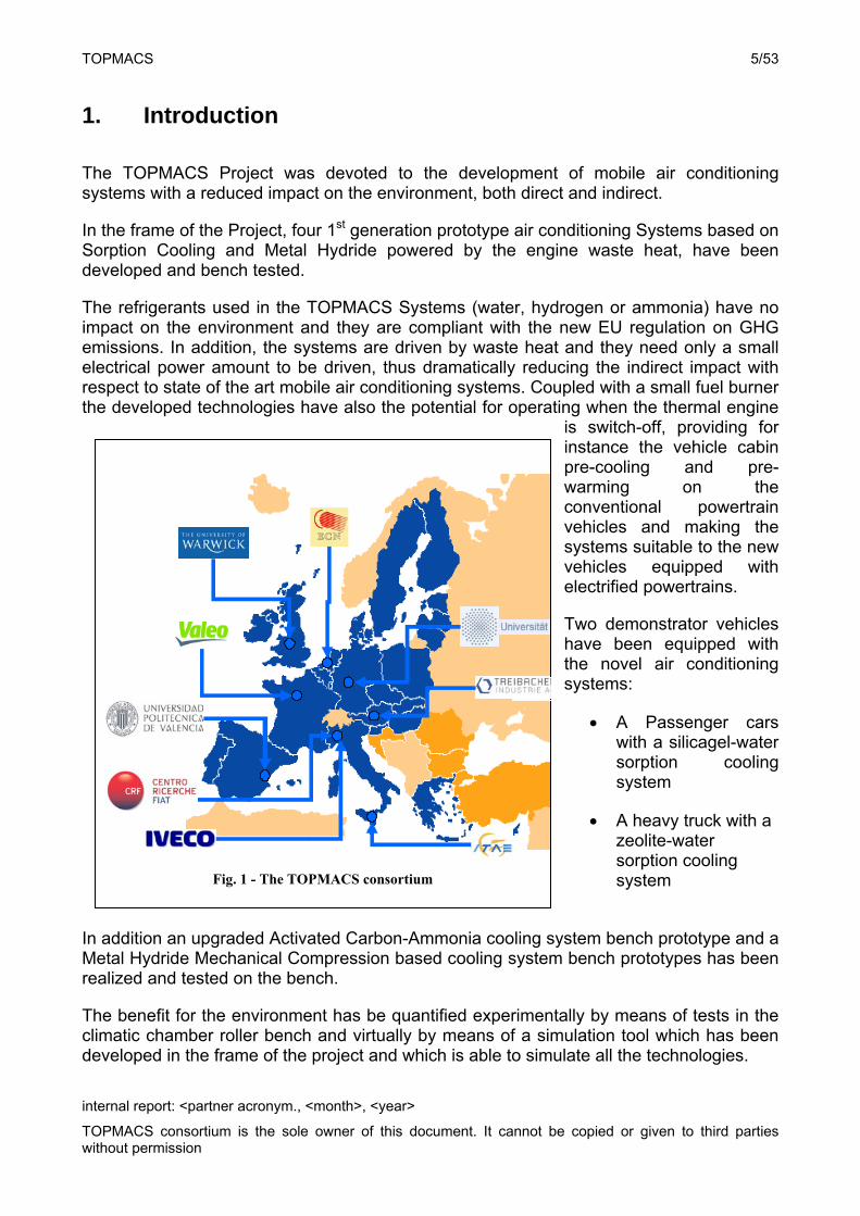
1. Introduction
The TOPMACS Project was devoted to the development of mobile air conditioning systems with a reduced impact on the environment, both direct and indirect.
In the frame of the Project, four 1st generation prototype air conditioning Systems based on Sorption Cooling and Metal Hydride powered by the engine waste heat, have been developed and bench tested.
The refrigerants used in the TOPMACS Systems (water, hydrogen or ammonia) have no impact on the environment and they are compliant with the new EU regulation on GHG emissions. In addition, the systems are driven by waste heat and they need only a small electrical power amount to be driven, thus dramatically reducing the indirect impact with respect to state of the art mobile air conditioning systems. Coupled with a small fuel burner the developed technologies have also the potential for operating when the thermal engine
is switch-off, providing for instance the vehicle cabin pre-cooling and pre-warming on the conventional powertrain vehicles and making the systems suitable to the new vehicles equipped with electrified powertrains.
Two demonstrator vehicles have been equipped with the novel air conditioning systems:
A Passenger cars with a silicagel-water sorption cooling system
A heavy truck with a zeolite-water sorption cooling system
In addition an upgraded Activated Carbon-Ammonia cooling system bench prototype and a Metal Hydride Mechanical Compression based cooling system bench prototypes has been realized and tested on the bench.
The benefit for the environment has be quantified experimentally by means of tests in the climatic chamber roller bench and virtually by means of a simulation tool which has been developed in the frame of the project and which is able to simulate all the technologies.
Fig. 1 - The TOPMACS consortium
TOPMACS 6/53
internal report: <partner acronym., <month>, <year>
TOPMACS consortium is the sole owner of this document. It cannot be copied or given to third parties without permission
A methodology to evaluate at the same time thermal comfort and the associated energy performance has been developed.
The Project has been carried out by a consortium constituted by a major OEM, a Tier1 supplier, an advance material supplier and five acknowledged excellence centers gathering skilled European scientists and engineers in this specific field.
Twentyseven students and three post-doc scholarships have been involved in the Project and 35 presentations to international events and papers have been published.
2. The TOPMACS A/C Key Features
2.1 Main Features Powered by the engine waste heat Use refrigerant with no GWP (compliant with the new EC regulation) The core of the system is a sorption heat pump
2.2 Key Results
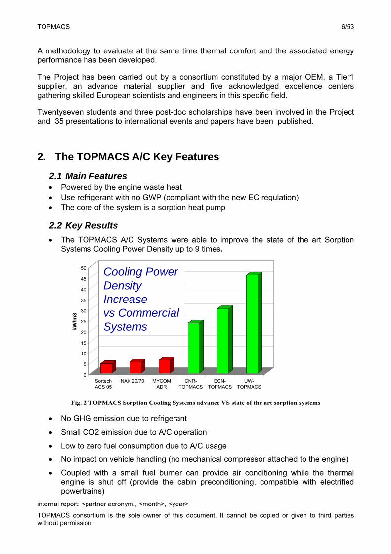
The TOPMACS A/C Systems were able to improve the state of the art Sorption Systems Cooling Power Density up to 9 times.
Fig. 2 TOPMACS Sorption Cooling Systems advance VS state of the art sorption systems
No GHG emission due to refrigerant
Small CO2 emission due to A/C operation
Low to zero fuel consumption due to A/C usage
No impact on vehicle handling (no mechanical compressor attached to the engine)
Coupled with a small fuel burner can provide air conditioning while the thermal engine is shut off (provide the cabin preconditioning, compatible with electrified powertrains)
0
5
10
15
20
25
30
35
40
45
50
kW/m
3
SortechACS 05
NAK 20/70 MYCOMADR
CNR-TOPMACS
ECN-TOPMACS
UW-TOPMACS
Cooling Power Density Increasevs Commercial Systems
TOPMACS 7/53
internal report: <partner acronym., <month>, <year>
TOPMACS consortium is the sole owner of this document. It cannot be copied or given to third parties without permission
3. The Truck Demonstrator with the Thermally Operated A/C System
The A/C system consists of a double bed adsorber, working in counter phase, connected with an evaporator and a condenser and driven by the low grade thermal energy coming from the engine cooling loop. The adsorbent material used belongs to a novel family of materials, called Functional Adsorbent Materials (FAMs), developed by Mitsubishi Chemical for applications where low temperature heat sources are available, while water was used as refrigerant. Firstly the performance evaluation was carried out at ITAE laboratory test bench simulating typical EU car air conditioning conditions. The experimental results obtained showed that the system is able to deliver an Average Cooling Power ranging between 1 and 2.3 kW for desorption temperature of about 90°C (Tev~7-16°C and Tcon~28-33°C). Secondly, onboard testing in a truck cabin provided by IVECO, demonstrated that the chiller is able to provide comfort conditions to the passengers.
The adsorption machine uses the available heat from the engine coolant loop and is designed to deliver about 2.3 kW cooling power for the cabin air conditioning. The working pair used is AQSOA®-FAM-Z02, produced by Mitsubishi Chemical Functional Products Inc., as adsorbent and water as adsorbate. In this description the design and practical realization of the prototype are discussed, afterwards, the performance evaluation under the EU car air conditioning testing conditions is presented. Finally, the on-board prototype installation and testing into the cabin of a IVECO truck are discussed.
3.1 The adsorption chiller: design and manufacturing
3.1.1 System constrains and requirements
Technical and economic feasibility of adsorption chillers for mobile applications requires specific needs in terms of lightness, compactness, cooling power density and operating available conditions (e.g. flow rates, temperature levels, etc).
In particular, the new adsorptive chiller was specifically developed to be installed in an Iveco Stralis truck thereby the design was studied taking into account the following system constrains and requirements provided by Iveco:
a) Availability of the waste heat in the engine cooling circuit: > 10kW at 90°C. b) Cooling power required: >2 kW for Severe European Summer Climate (35°C, 60 %
RH). c) Maximum temperature drop along the engine cooling circuit: < 5°C. d) Mass flow of the cooling fluid: 15-20 l/min. e) Auxiliary burner available on the truck for cooling during driver rest in parking areas. f) Available space for installation: 150 -170 dm3. g) Maximum weight allowed: 35 kg.
TOPMACS 8/53
internal report: <partner acronym., <month>, <year>
TOPMACS consortium is the sole owner of this document. It cannot be copied or given to third parties without permission
3.1.2 Design and realization of the adsorptive prototype
The adsorption air conditioner consists of two adsorbers connected by vacuum valves to a single evaporator and condenser. The two adsorbers operate in counter-phase ensuring a quasi-continuous useful effect. External water circuits are used to provide/remove thermal energy to the above mentioned components. The system is operated without heat or mass recovery in order to minimize the cycle time and to increase the Specific Cooling Power of the machine.
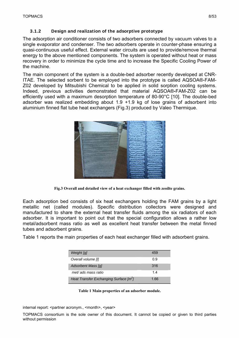
The main component of the system is a double-bed adsorber recently developed at CNR-ITAE. The selected sorbent to be employed into the prototype is called AQSOA®-FAM-Z02 developed by Mitsubishi Chemical to be applied in solid sorption cooling systems. Indeed, previous activities demonstrated that material AQSOA®-FAM-Z02 can be efficiently used with a maximum desorption temperature of 80-90°C [10]. The double-bed adsorber was realized embedding about 1.9 +1.9 kg of lose grains of adsorbent into aluminium finned flat tube heat exchangers (Fig.3) produced by Valeo Thermique.
Fig.3 Overall and detailed view of a heat exchanger filled with zeoilte grains.
Each adsorption bed consists of six heat exchangers holding the FAM grains by a light metallic net (called modules). Specific distribution collectors were designed and manufactured to share the external heat transfer fluids among the six radiators of each adsorber. It is important to point out that the special configuration allows a rather low metal/adsorbent mass ratio as well as excellent heat transfer between the metal finned tubes and adsorbent grains.
Table 1 reports the main properties of each heat exchanger filled with adsorbent grains.
Weight [g] 459
Overall volume [l] 0.9
Adsorbent Mass [g] 316
met/ ads mass ratio 1.4
Heat Transfer Exchanging Surface [m2] 1.66
Table 1 Main properties of an adsorber module.
TOPMACS 9/53
internal report: <partner acronym., <month>, <year>
TOPMACS consortium is the sole owner of this document. It cannot be copied or given to third parties without permission
The vacuum chambers containing the double adsorber have been specifically designed to fit the adsorbent bed and present various flanges that allow the connection with the other components of the prototype and the installation of the measurement devices (pressure gauges, temperature sensors), necessary to control and manage the system during testing. To reduce the weight and volume of the system, the chambers were realized in aluminium while compact evaporator and condenser were specifically built using finned-tubes heat exchangers which offer very high exchange surface. The connections between adsorbent beds and condenser/evaporator are regulated by means of automatic vacuum valves. A set of electric valves is used to control the circuits for the external heat transfer fluids.
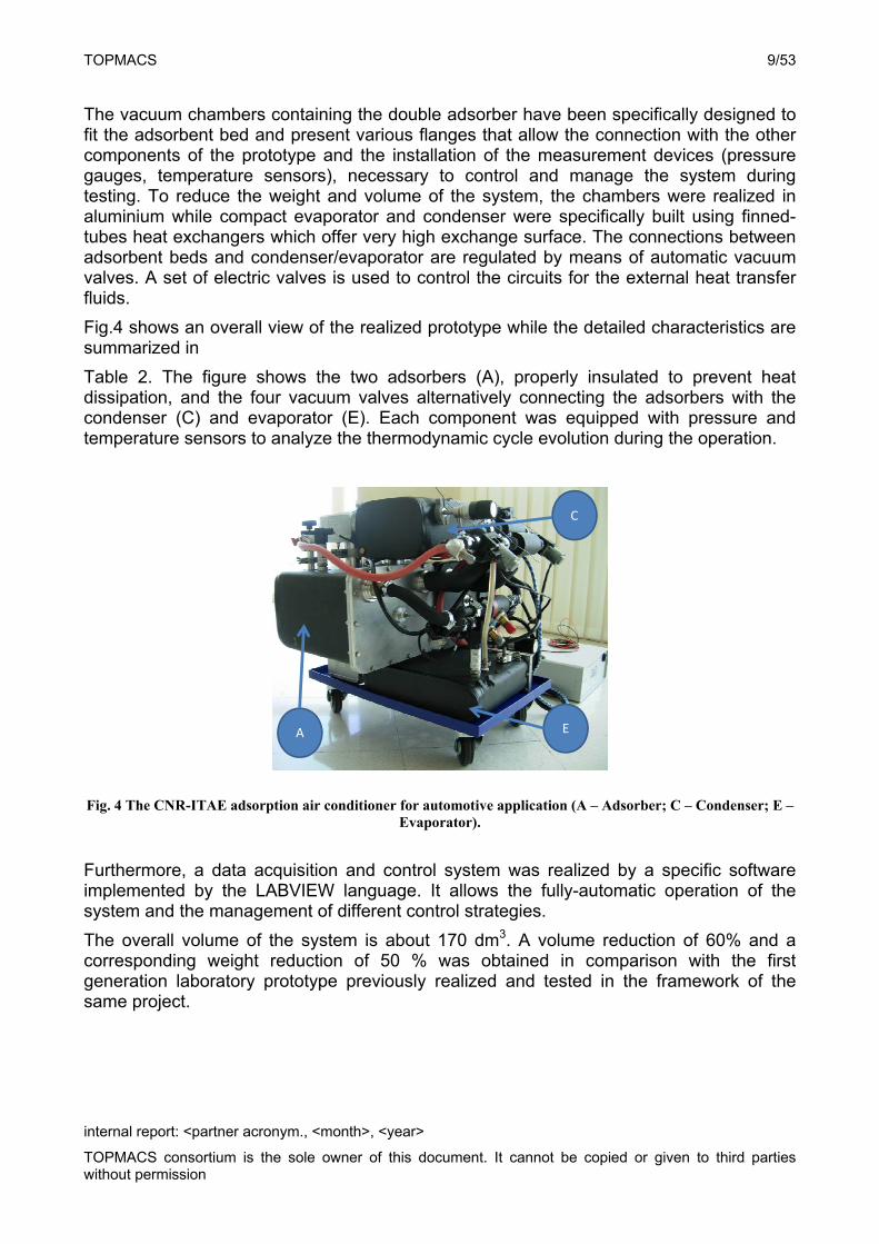
Fig.4 shows an overall view of the realized prototype while the detailed characteristics are summarized in
Table 2. The figure shows the two adsorbers (A), properly insulated to prevent heat dissipation, and the four vacuum valves alternatively connecting the adsorbers with the condenser (C) and evaporator (E). Each component was equipped with pressure and temperature sensors to analyze the thermodynamic cycle evolution during the operation.
E
C
A
Fig. 4 The CNR-ITAE adsorption air conditioner for automotive application (A – Adsorber; C – Condenser; E – Evaporator).
Furthermore, a data acquisition and control system was realized by a specific software implemented by the LABVIEW language. It allows the fully-automatic operation of the system and the management of different control strategies.
The overall volume of the system is about 170 dm3. A volume reduction of 60% and a corresponding weight reduction of 50 % was obtained in comparison with the first generation laboratory prototype previously realized and tested in the framework of the same project.
TOPMACS 10/53
internal report: <partner acronym., <month>, <year>
TOPMACS consortium is the sole owner of this document. It cannot be copied or given to third parties without permission
Type of adsorbent AQSOA®-FAM-Z02
Mass of adsorbent in each adsorber 1.9 kg
Weight of HEXs used for each adsorber 2.7 kg
Total weight of the double-bed adsorber (vacuum chamber included)
15+15 kg
Weight of the condenser+evaporator 15+15 kg
Overall volume of the prototype 170 dm3
Total weight of the prototype 60 kg
Table 2 Main properties of the adsorption air conditioner.
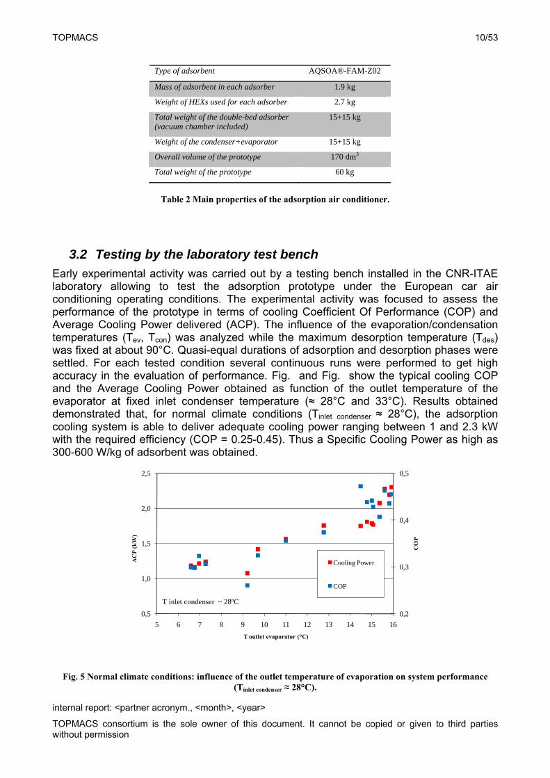
3.2 Testing by the laboratory test bench
Early experimental activity was carried out by a testing bench installed in the CNR-ITAE laboratory allowing to test the adsorption prototype under the European car air conditioning operating conditions. The experimental activity was focused to assess the performance of the prototype in terms of cooling Coefficient Of Performance (COP) and Average Cooling Power delivered (ACP). The influence of the evaporation/condensation temperatures (Tev, Tcon) was analyzed while the maximum desorption temperature (Tdes) was fixed at about 90°C. Quasi-equal durations of adsorption and desorption phases were settled. For each tested condition several continuous runs were performed to get high accuracy in the evaluation of performance. Fig. and Fig. show the typical cooling COP and the Average Cooling Power obtained as function of the outlet temperature of the evaporator at fixed inlet condenser temperature (≈ 28°C and 33°C). Results obtained demonstrated that, for normal climate conditions (Tinlet condenser ≈ 28°C), the adsorption cooling system is able to deliver adequate cooling power ranging between 1 and 2.3 kW with the required efficiency (COP = 0.25-0.45). Thus a Specific Cooling Power as high as 300-600 W/kg of adsorbent was obtained.
0,2
0,3
0,4
0,5
0,5
1,0
1,5
2,0
2,5
5 6 7 8 9 10 11 12 13 14 15 16
CO
P
AC
P (k
W)
T outlet evaporator (°C)
Cooling Power
COP
T inlet condenser ~ 28°C
Fig. 5 Normal climate conditions: influence of the outlet temperature of evaporation on system performance (Tinlet condenser ≈ 28°C).
TOPMACS 11/53
internal report: <partner acronym., <month>, <year>
TOPMACS consortium is the sole owner of this document. It cannot be copied or given to third parties without permission
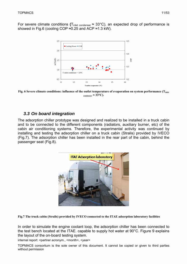
For severe climate conditions (Tinlet condenser ≈ 33°C), an expected drop of performance is showed in Fig.6 (cooling COP ≈0.25 and ACP ≈1.3 kW).
0,2
0,3
0,4
0,5
0,5
1,0
1,5
2,0
2,5
11 12 13 14 15 16
CO
P
AC
P (k
W)
T outlet evaporator (°C)
Cooling Power COP
T inlet condenser ~ 33°C
Fig. 6 Severe climate conditions: influence of the outlet temperature of evaporation on system performance (Tinlet
condenser ≈ 33°C).
3.3 On board integration
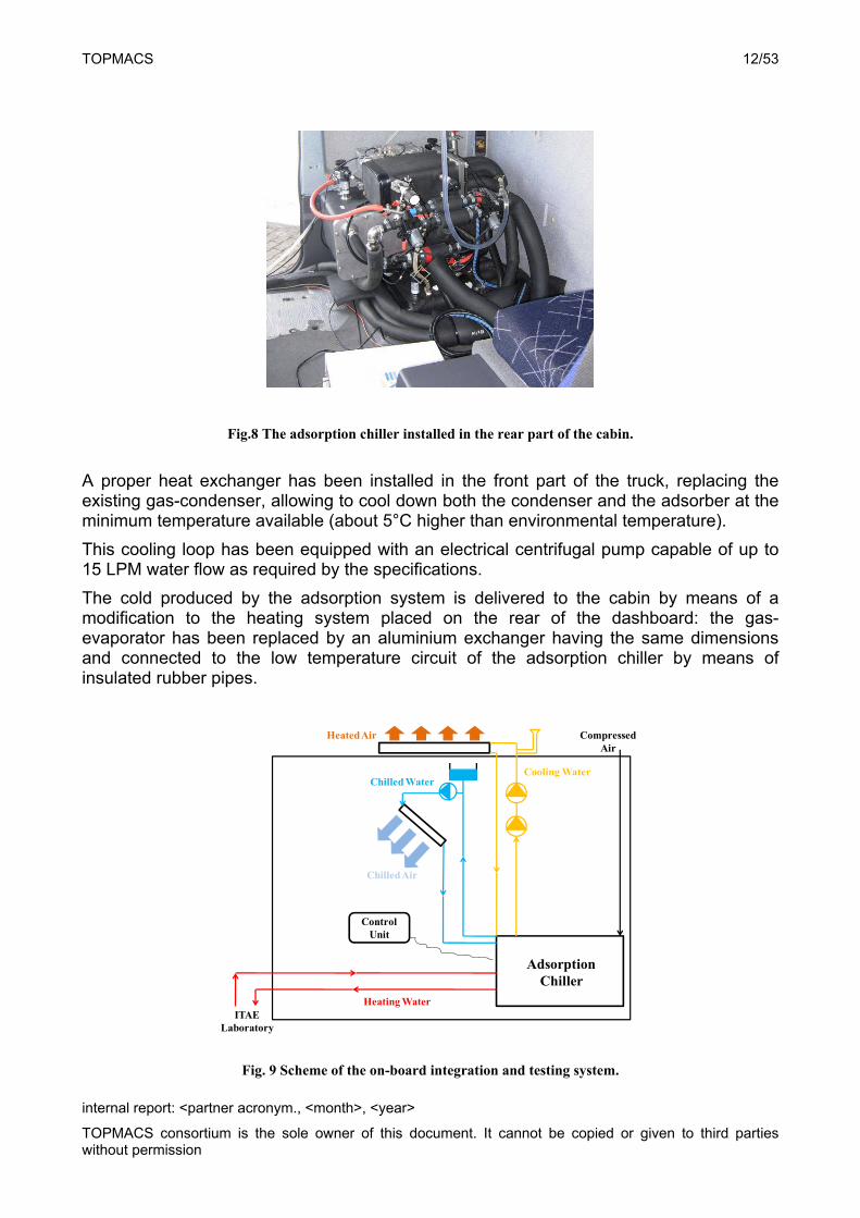
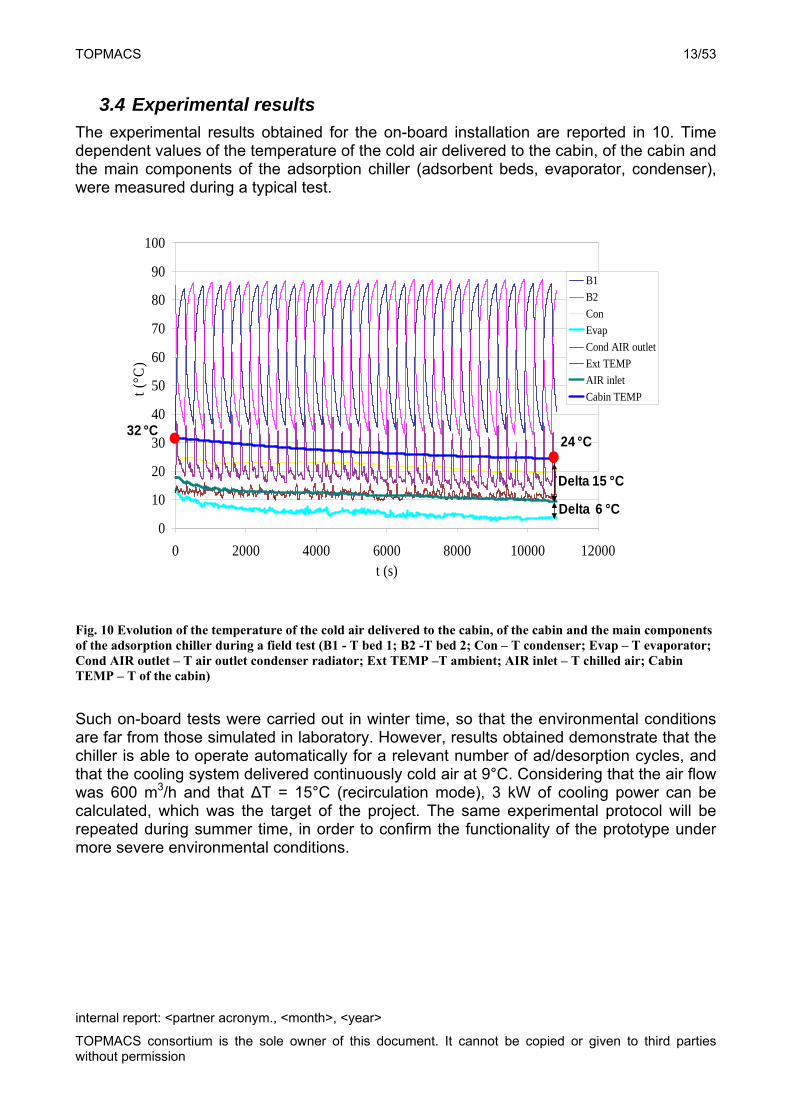
The adsorption chiller prototype was designed and realized to be installed in a truck cabin and to be connected to the different components (radiators, auxiliary burner, etc) of the cabin air conditioning systems. Therefore, the experimental activity was continued by installing and testing the adsorption chiller on a truck cabin (Stralis) provided by IVECO (Fig.7). The adsorption chiller has been installed in the rear part of the cabin, behind the passenger seat (Fig.8).
Fig.7 The truck cabin (Stralis) provided by IVECO connected to the ITAE adsorption laboratory facilities
In order to simulate the engine coolant loop, the adsorption chiller has been connected to the test bench located at the ITAE. capable to supply hot water at 90°C. Figure 9 explains the layout of the on-board testing system.
TOPMACS 12/53
internal report: <partner acronym., <month>, <year>
TOPMACS consortium is the sole owner of this document. It cannot be copied or given to third parties without permission
Fig.8 The adsorption chiller installed in the rear part of the cabin.
A proper heat exchanger has been installed in the front part of the truck, replacing the existing gas-condenser, allowing to cool down both the condenser and the adsorber at the minimum temperature available (about 5°C higher than environmental temperature).
This cooling loop has been equipped with an electrical centrifugal pump capable of up to 15 LPM water flow as required by the specifications.
The cold produced by the adsorption system is delivered to the cabin by means of a modification to the heating system placed on the rear of the dashboard: the gas-evaporator has been replaced by an aluminium exchanger having the same dimensions and connected to the low temperature circuit of the adsorption chiller by means of insulated rubber pipes.
ITAE Laboratory
CompressedAir
Control Unit
Chilled Water
ChilledAir
AdsorptionChiller
Cooling Water
Heating Water
HeatedAir
Fig. 9 Scheme of the on-board integration and testing system.
TOPMACS 13/53
internal report: <partner acronym., <month>, <year>
TOPMACS consortium is the sole owner of this document. It cannot be copied or given to third parties without permission
3.4 Experimental results
The experimental results obtained for the on-board installation are reported in 10. Time dependent values of the temperature of the cold air delivered to the cabin, of the cabin and the main components of the adsorption chiller (adsorbent beds, evaporator, condenser), were measured during a typical test.
0
10
20
30
40
50
60
70
80
90
100
0 2000 4000 6000 8000 10000 12000t (s)
t (°C
)
B1
B2
Con
Evap
Cond AIR outlet
Ext TEMP
AIR inlet
Cabin TEMP
Delta 6 °C
Delta 15 °C
32 °C24 °C
Fig. 10 Evolution of the temperature of the cold air delivered to the cabin, of the cabin and the main components of the adsorption chiller during a field test (B1 - T bed 1; B2 -T bed 2; Con – T condenser; Evap – T evaporator; Cond AIR outlet – T air outlet condenser radiator; Ext TEMP –T ambient; AIR inlet – T chilled air; Cabin TEMP – T of the cabin)
Such on-board tests were carried out in winter time, so that the environmental conditions are far from those simulated in laboratory. However, results obtained demonstrate that the chiller is able to operate automatically for a relevant number of ad/desorption cycles, and that the cooling system delivered continuously cold air at 9°C. Considering that the air flow was 600 m3/h and that ΔT = 15°C (recirculation mode), 3 kW of cooling power can be calculated, which was the target of the project. The same experimental protocol will be repeated during summer time, in order to confirm the functionality of the prototype under more severe environmental conditions.
TOPMACS 14/53
internal report: <partner acronym., <month>, <year>
TOPMACS consortium is the sole owner of this document. It cannot be copied or given to third parties without permission
3.5 CONCLUSIONS
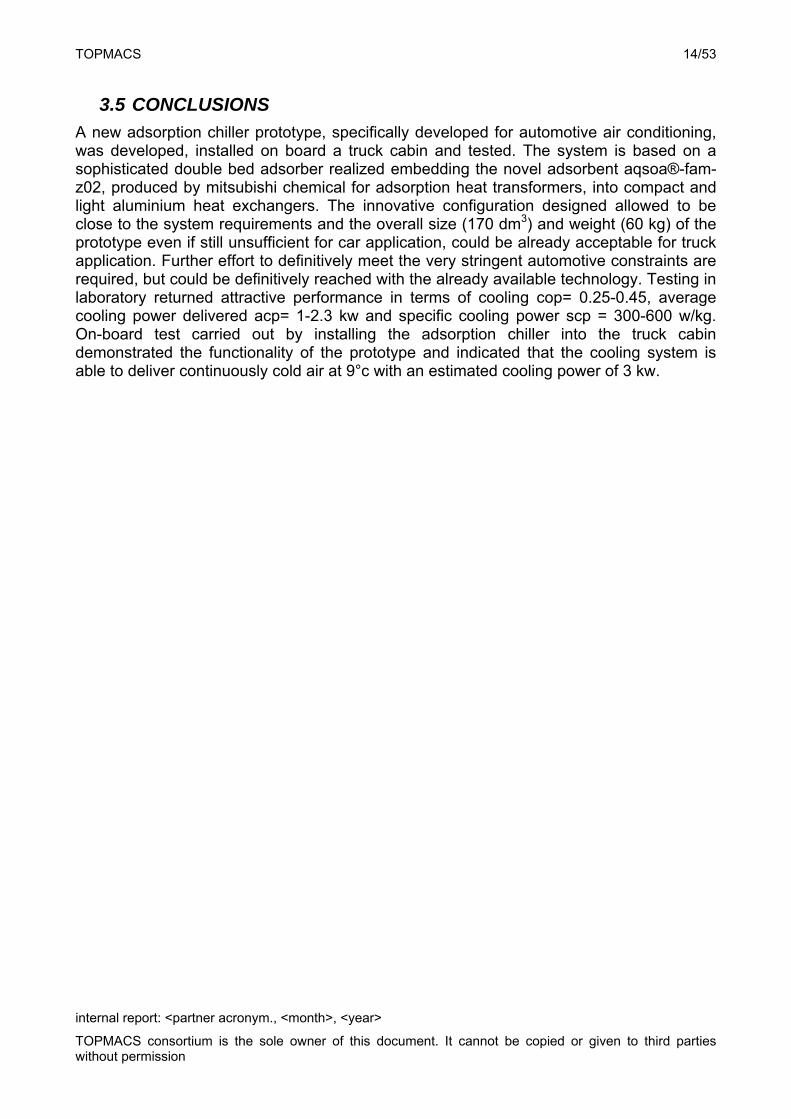
A new adsorption chiller prototype, specifically developed for automotive air conditioning, was developed, installed on board a truck cabin and tested. The system is based on a sophisticated double bed adsorber realized embedding the novel adsorbent aqsoa®-fam-z02, produced by mitsubishi chemical for adsorption heat transformers, into compact and light aluminium heat exchangers. The innovative configuration designed allowed to be close to the system requirements and the overall size (170 dm3) and weight (60 kg) of the prototype even if still unsufficient for car application, could be already acceptable for truck application. Further effort to definitively meet the very stringent automotive constraints are required, but could be definitively reached with the already available technology. Testing in laboratory returned attractive performance in terms of cooling cop= 0.25-0.45, average cooling power delivered acp= 1-2.3 kw and specific cooling power scp = 300-600 w/kg. On-board test carried out by installing the adsorption chiller into the truck cabin demonstrated the functionality of the prototype and indicated that the cooling system is able to deliver continuously cold air at 9°c with an estimated cooling power of 3 kw.
TOPMACS 15/53
internal report: <partner acronym., <month>, <year>
TOPMACS consortium is the sole owner of this document. It cannot be copied or given to third parties without permission
4. The passenger car with the A/C System working on the engine coolant waste heat
A complete A/C System driven by the engine coolant waste heat was design and installed on a B segment reference car (FIAT Grande Punto). The core of the system is a sorption chiller designed, constructed and first tested in the laboratory of ECN. The performance under various static operating conditions was firstly determined in the laboratory. The system can produce 2 kW of chilling power with a COP of 0.4. The overall on-board car A/C system which uses the sorption cooler as cooling power generator and the engine coolant waste heat as the primary energy source, was design and then installed by CRF on the Grande Punto demonstrator. The system includes three fluid circuits necessary to drive to sorption cooler: the heating circuit (engine coolant), the cooling circuit connected to the engine radiator, was connected to the three flui circuit which area modified and cooling systems of the car and tested in different conditions .The performance in the car was comparable to the performance in the lab, indicating that system integration was successful. The amount of waste heat that is freely available in the engine coolant circuit as well as its temperature level is sufficient to drive the adsorption cooling system and to produce enough cold to keep comfortable interior temperatures. In conclusion it has been demonstrated that a waste heat driven adsorption cooling system can be applied for comfort cooling purposes in a car.
4.1 Adsorption cooling system development
4.1.1 Overall system lay-out
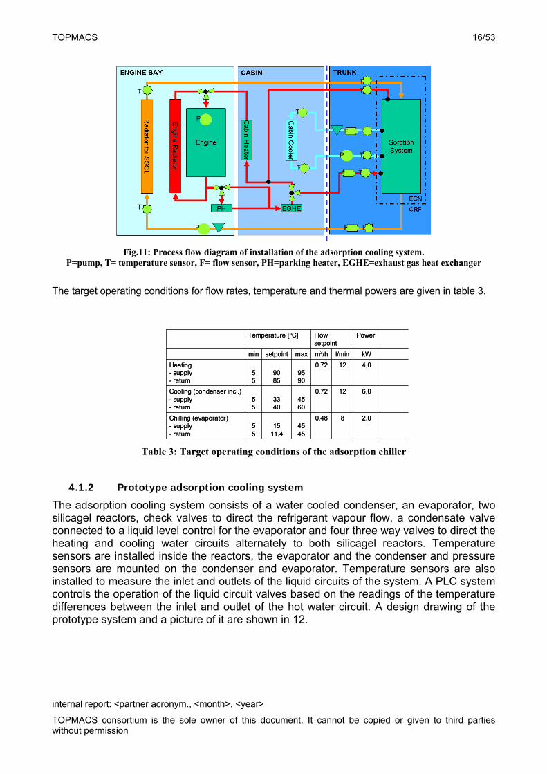
A passenger car of the type Fiat Grande Punto was selected as the demonstration car. This car is representative for a modern European B-segment (compact) car. It has a 1.4 dm3 petrol engine. Because the size of the thermal compressor section of the adsorption cooling system was too large to allow installation in the original engine bay, the prototype was installed in the trunk space. Because of the trunk location in the car an air cooled condenser could not be applied. Instead, a water cooled condenser is used. The heat rejection of the adsorption system from the condenser and the cooled silicagel reactor is done by an additional cooling water circuit that removes the heat through a radiator in the front of the car. The cold produced in the evaporator is transferred to a chilled water loop. The chilled water loop is pumped through the cabin air-cooler for cooling down the air that re-circulates in the passenger compartment. The system components and liquid circuits lay-out are shown in 11. Each liquid circuit has a pump, a flow measurement device and temperature sensors at the inlet and outlet of the thermal components. The hot water circuit (or engine cooling water loop) has an exhaust gas heat exchanger (EGHE) which transfers part of the heat of the exhaust gas to the hot water. This reduces the time required to reach steady state operating temperatures of the engine. It also reduces the start-uptime of the sorption cooling system.
TOPMACS 16/53
internal report: <partner acronym., <month>, <year>
TOPMACS consortium is the sole owner of this document. It cannot be copied or given to third parties without permission
Fig.11: Process flow diagram of installation of the adsorption cooling system.
P=pump, T= temperature sensor, F= flow sensor, PH=parking heater, EGHE=exhaust gas heat exchanger
The target operating conditions for flow rates, temperature and thermal powers are given in table 3.
2,080.484545
1511.4
55
Chilling (evaporator)- supply- return
6,0120.724560
3340
55
Cooling (condenser incl.)- supply- return
4,0120.729590
9085
55
Heating- supply- return
kWl/minm3/hmaxsetpointmin
PowerFlow setpoint
Temperature [°C]
2,080.484545
1511.4
55
Chilling (evaporator)- supply- return
6,0120.724560
3340
55
Cooling (condenser incl.)- supply- return
4,0120.729590
9085
55
Heating- supply- return
kWl/minm3/hmaxsetpointmin
PowerFlow setpoint
Temperature [°C]
Table 3: Target operating conditions of the adsorption chiller
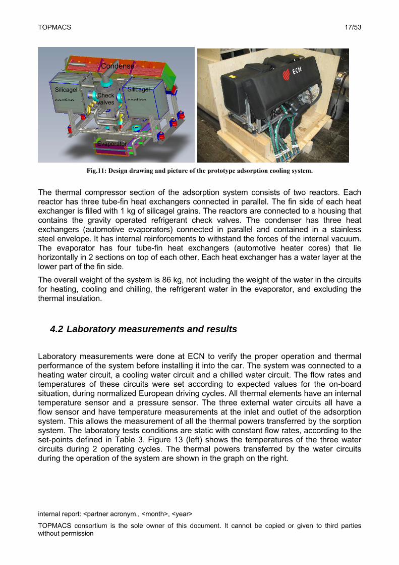
4.1.2 Prototype adsorption cooling system
The adsorption cooling system consists of a water cooled condenser, an evaporator, two silicagel reactors, check valves to direct the refrigerant vapour flow, a condensate valve connected to a liquid level control for the evaporator and four three way valves to direct the heating and cooling water circuits alternately to both silicagel reactors. Temperature sensors are installed inside the reactors, the evaporator and the condenser and pressure sensors are mounted on the condenser and evaporator. Temperature sensors are also installed to measure the inlet and outlets of the liquid circuits of the system. A PLC system controls the operation of the liquid circuit valves based on the readings of the temperature differences between the inlet and outlet of the hot water circuit. A design drawing of the prototype system and a picture of it are shown in 12.
T
T
TFP
P
F
F
P
T
T
T
T
T
T
T
TOPMACS 17/53
internal report: <partner acronym., <month>, <year>
TOPMACS consortium is the sole owner of this document. It cannot be copied or given to third parties without permission
Fig.11: Design drawing and picture of the prototype adsorption cooling system.
The thermal compressor section of the adsorption system consists of two reactors. Each reactor has three tube-fin heat exchangers connected in parallel. The fin side of each heat exchanger is filled with 1 kg of silicagel grains. The reactors are connected to a housing that contains the gravity operated refrigerant check valves. The condenser has three heat exchangers (automotive evaporators) connected in parallel and contained in a stainless steel envelope. It has internal reinforcements to withstand the forces of the internal vacuum. The evaporator has four tube-fin heat exchangers (automotive heater cores) that lie horizontally in 2 sections on top of each other. Each heat exchanger has a water layer at the lower part of the fin side.
The overall weight of the system is 86 kg, not including the weight of the water in the circuits for heating, cooling and chilling, the refrigerant water in the evaporator, and excluding the thermal insulation.
4.2 Laboratory measurements and results
Laboratory measurements were done at ECN to verify the proper operation and thermal performance of the system before installing it into the car. The system was connected to a heating water circuit, a cooling water circuit and a chilled water circuit. The flow rates and temperatures of these circuits were set according to expected values for the on-board situation, during normalized European driving cycles. All thermal elements have an internal temperature sensor and a pressure sensor. The three external water circuits all have a flow sensor and have temperature measurements at the inlet and outlet of the adsorption system. This allows the measurement of all the thermal powers transferred by the sorption system. The laboratory tests conditions are static with constant flow rates, according to the set-points defined in Table 3. Figure 13 (left) shows the temperatures of the three water circuits during 2 operating cycles. The thermal powers transferred by the water circuits during the operation of the system are shown in the graph on the right.
Condense
Evaporator
Silicagel
section
Silicagel
sectionCheck valves
TOPMACS 18/53
internal report: <partner acronym., <month>, <year>
TOPMACS consortium is the sole owner of this document. It cannot be copied or given to third parties without permission
10,0
20,0
30,0
40,0
50,0
60,0
70,0
80,0
90,0
0:0
0:0
0
0:0
1:0
0
0:0
2:0
0
0:0
3:0
0
0:0
4:0
0
0:0
5:0
0
0:0
6:0
0
0:0
7:0
0
0:0
8:0
0
0:0
9:0
0
0:1
0:0
0
0:1
1:0
0
10,0
20,0
30,0
40,0
50,0
60,0
70,0
80,0
90,0
Time [h:mm:ss]
Temperature [°C] Temperature [°C]
-30,0
-24,0
-18,0
-12,0
-6,0
0,0
6,0
12,0
18,0
24,0
30,0
0:0
0:0
0
0:0
1:0
0
0:0
2:0
0
0:0
3:0
0
0:0
4:0
0
0:0
5:0
0
0:0
6:0
0
0:0
7:0
0
0:0
8:0
0
0:0
9:0
0
0:1
0:0
0
0:1
1:0
0
-7,0
-6,0
-5,0
-4,0
-3,0
-2,0
-1,0
0,0
1,0
2,0
3,0
P heating [kW] P cooling [kW] P chilling [kW]
P 440 [kW] P cond [kW] P evap [kW]
Time [h:mm:ss]
Power [kW] Power [kW]
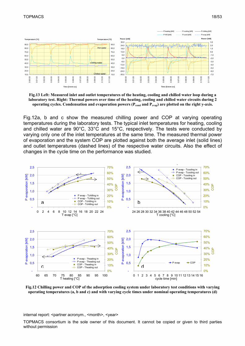
Fig.13 Left: Measured inlet and outlet temperatures of the heating, cooling and chilled water loop during a laboratory test. Right: Thermal powers over time of the heating, cooling and chilled water circuits during 2
operating cycles. Condensation and evaporation powers (Pcond and Pevap) are plotted on the right y-axis.
Fig.12a, b and c show the measured chilling power and COP at varying operating temperatures during the laboratory tests. The typical inlet temperatures for heating, cooling and chilled water are 90°C, 33°C and 15°C, respectively. The tests were conducted by varying only one of the inlet temperatures at the same time. The measured thermal power of evaporation and the system COP are plotted against both the average inlet (solid lines) and outlet temperatures (dashed lines) of the respective water circuits. Also the effect of changes in the cycle time on the performance was studied.
-
0,5
1,0
1,5
2,0
2,5
0 2 4 6 8 10 12 14 16 18 20 22 24T evap [°C]
P e
vapo
ratio
n [k
W]
0%
10%
20%
30%
40%
50%
60%
70%
CO
P
P evap - Tchilling inP evap - Tchlling outCOP - Tchilling inCOP - Tchilling out
y
-
0,5
1,0
1,5
2,0
2,5
24 26 28 30 32 34 36 38 40 42 44 46 48 50 52 54T cooling [°C]
P e
vap
orat
ion
[kW
]
0%
10%
20%
30%
40%
50%
60%
70%
CO
P
P evap - Tcooling inP evap - Tcooling outCOP - Tcooling inCOP - Tcooling out
y
-
0,5
1,0
1,5
2,0
2,5
60 65 70 75 80 85 90 95 100T heating [°C]
P e
vapo
ratio
n [k
W]
0%
10%
20%
30%
40%
50%
60%
70%
CO
P
P evap - Theating inP evap - Theating outCOP - Theating inCOP - Theating out
-
0,5
1,0
1,5
2,0
2,5
0 1 2 3 4 5 6 7 8 9 10 11 12 13 14 15 16cycle time [min]
P e
vapo
ratio
n [k
W]
0%
10%
20%
30%
40%
50%
60%
70%
CO
P
P evap COP
Fig.12 Chilling power and COP of the adsorption cooling system under laboratory test conditions with varying
operating temperatures (a, b and c) and with varying cycle times under nominal operating temperatures (d)
cooling water
Hot water
Chilled water
a b
c d
TOPMACS 19/53
internal report: <partner acronym., <month>, <year>
TOPMACS consortium is the sole owner of this document. It cannot be copied or given to third parties without permission
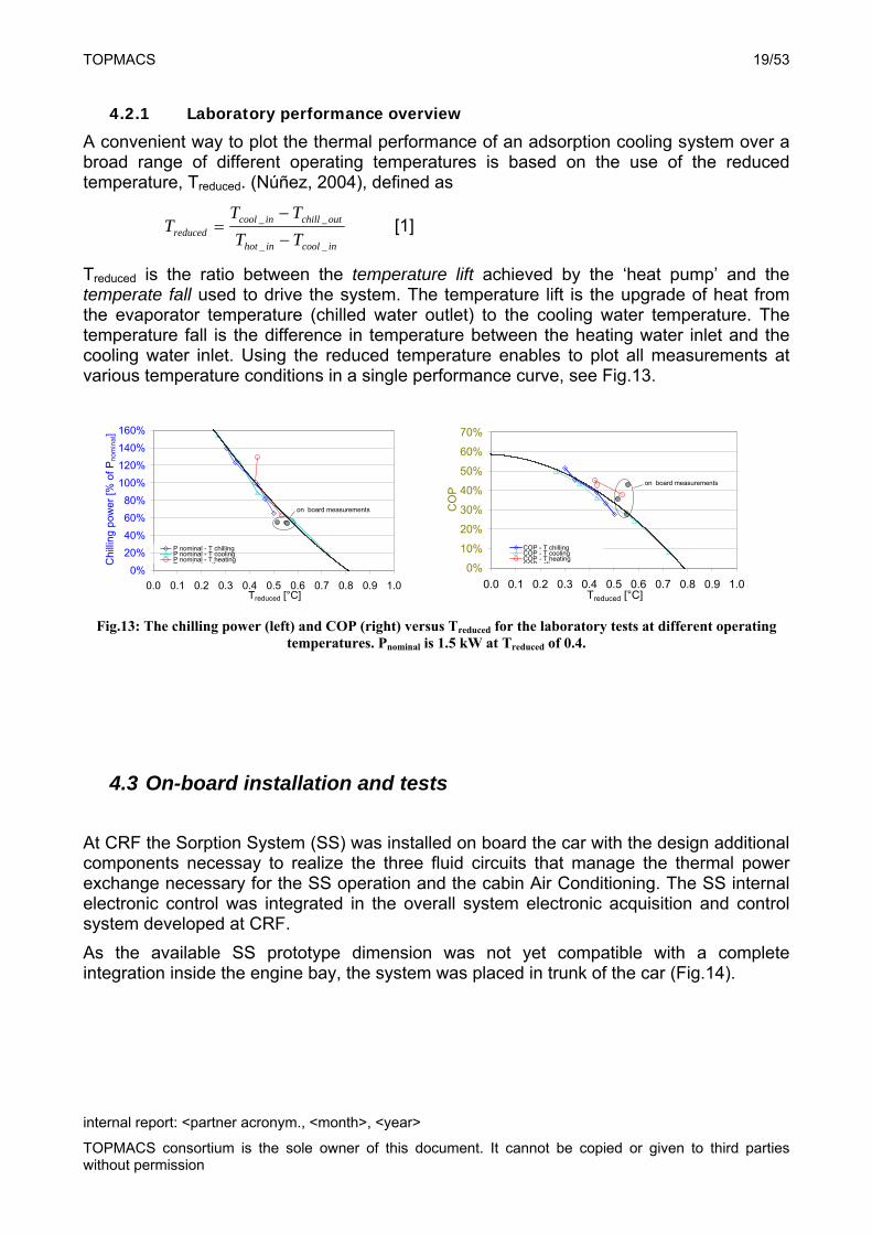
4.2.1 Laboratory performance overview
A convenient way to plot the thermal performance of an adsorption cooling system over a broad range of different operating temperatures is based on the use of the reduced temperature, Treduced. (Núñez, 2004), defined as
incoolinhot
outchillincoolreduced TT
TTT
__
__
[1]
Treduced is the ratio between the temperature lift achieved by the ‘heat pump’ and the temperate fall used to drive the system. The temperature lift is the upgrade of heat from the evaporator temperature (chilled water outlet) to the cooling water temperature. The temperature fall is the difference in temperature between the heating water inlet and the cooling water inlet. Using the reduced temperature enables to plot all measurements at various temperature conditions in a single performance curve, see Fig.13.
0%
20%
40%
60%
80%
100%
120%
140%
160%
0.0 0.1 0.2 0.3 0.4 0.5 0.6 0.7 0.8 0.9 1.0Treduced [°C]
Chi
lling
pow
er
[% o
f Pn
om
ina
l]
P nominal - T chillingP nominal - T coolingP nominal - T heatingP i l ll
on board measurements
0%
10%
20%
30%
40%
50%
60%
70%
0.0 0.1 0.2 0.3 0.4 0.5 0.6 0.7 0.8 0.9 1.0Treduced [°C]
CO
P
COP - T chillingCOP - T coolingCOP - T heatingCOP all
on board measurements
Fig.13: The chilling power (left) and COP (right) versus Treduced for the laboratory tests at different operating
temperatures. Pnominal is 1.5 kW at Treduced of 0.4.
4.3 On-board installation and tests
At CRF the Sorption System (SS) was installed on board the car with the design additional components necessay to realize the three fluid circuits that manage the thermal power exchange necessary for the SS operation and the cabin Air Conditioning. The SS internal electronic control was integrated in the overall system electronic acquisition and control system developed at CRF.
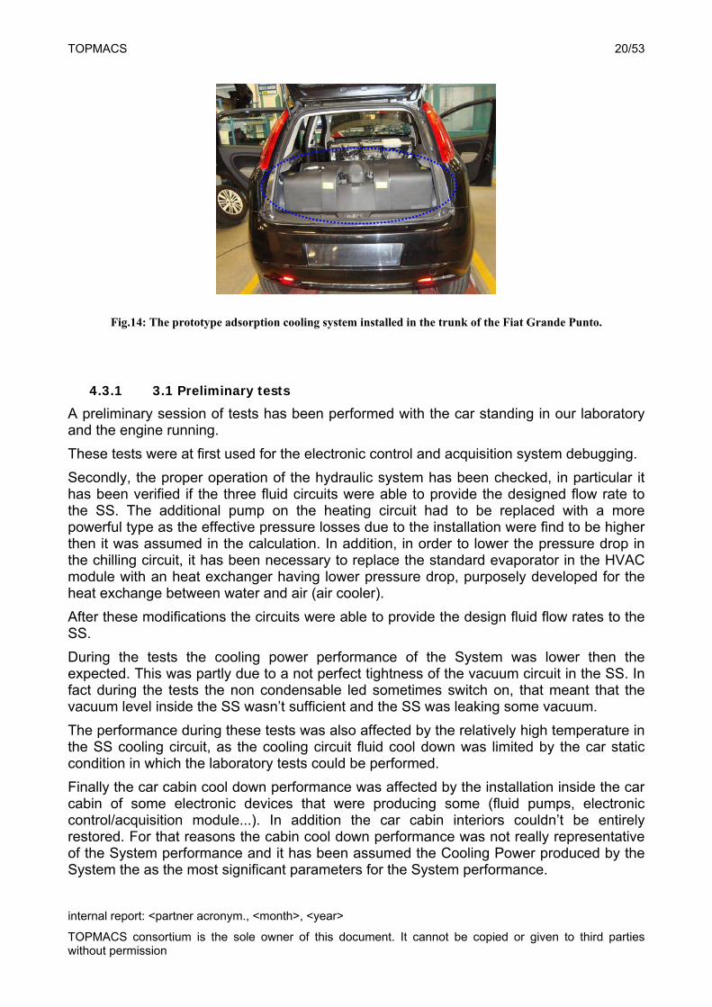
As the available SS prototype dimension was not yet compatible with a complete integration inside the engine bay, the system was placed in trunk of the car (Fig.14).
TOPMACS 20/53
internal report: <partner acronym., <month>, <year>
TOPMACS consortium is the sole owner of this document. It cannot be copied or given to third parties without permission
Fig.14: The prototype adsorption cooling system installed in the trunk of the Fiat Grande Punto.
4.3.1 3.1 Preliminary tests
A preliminary session of tests has been performed with the car standing in our laboratory and the engine running.
These tests were at first used for the electronic control and acquisition system debugging.
Secondly, the proper operation of the hydraulic system has been checked, in particular it has been verified if the three fluid circuits were able to provide the designed flow rate to the SS. The additional pump on the heating circuit had to be replaced with a more powerful type as the effective pressure losses due to the installation were find to be higher then it was assumed in the calculation. In addition, in order to lower the pressure drop in the chilling circuit, it has been necessary to replace the standard evaporator in the HVAC module with an heat exchanger having lower pressure drop, purposely developed for the heat exchange between water and air (air cooler).
After these modifications the circuits were able to provide the design fluid flow rates to the SS.
During the tests the cooling power performance of the System was lower then the expected. This was partly due to a not perfect tightness of the vacuum circuit in the SS. In fact during the tests the non condensable led sometimes switch on, that meant that the vacuum level inside the SS wasn’t sufficient and the SS was leaking some vacuum.
The performance during these tests was also affected by the relatively high temperature in the SS cooling circuit, as the cooling circuit fluid cool down was limited by the car static condition in which the laboratory tests could be performed.
Finally the car cabin cool down performance was affected by the installation inside the car cabin of some electronic devices that were producing some (fluid pumps, electronic control/acquisition module...). In addition the car cabin interiors couldn’t be entirely restored. For that reasons the cabin cool down performance was not really representative of the System performance and it has been assumed the Cooling Power produced by the System the as the most significant parameters for the System performance.
TOPMACS 21/53
internal report: <partner acronym., <month>, <year>
TOPMACS consortium is the sole owner of this document. It cannot be copied or given to third parties without permission
4.3.2 3.2 Test in the climatic roller bench room
A series of test have been performed in the climatic roller bench room in different conditions to check the system operation and to arrange the system parameters in order to optimize the system performance.
The following tests have been performed:
@20°C ambient temperature, 60kmh+100kph vehicle speed
@20°C 100kph reduced chilling flow rate
@20°C 100kph, additional pump on the heating loop switch ON & OFF
@20°C NEDC additional pump on the heating loop ON
@20°C NEDC additional pump on the heating loop OFF
@28°C 100kph, additional pump on the heating loop switch ON & OFF
@28°C NEDC additional pump on the heating loop ON
@28°C NEDC additional pump on the heating loop OFF
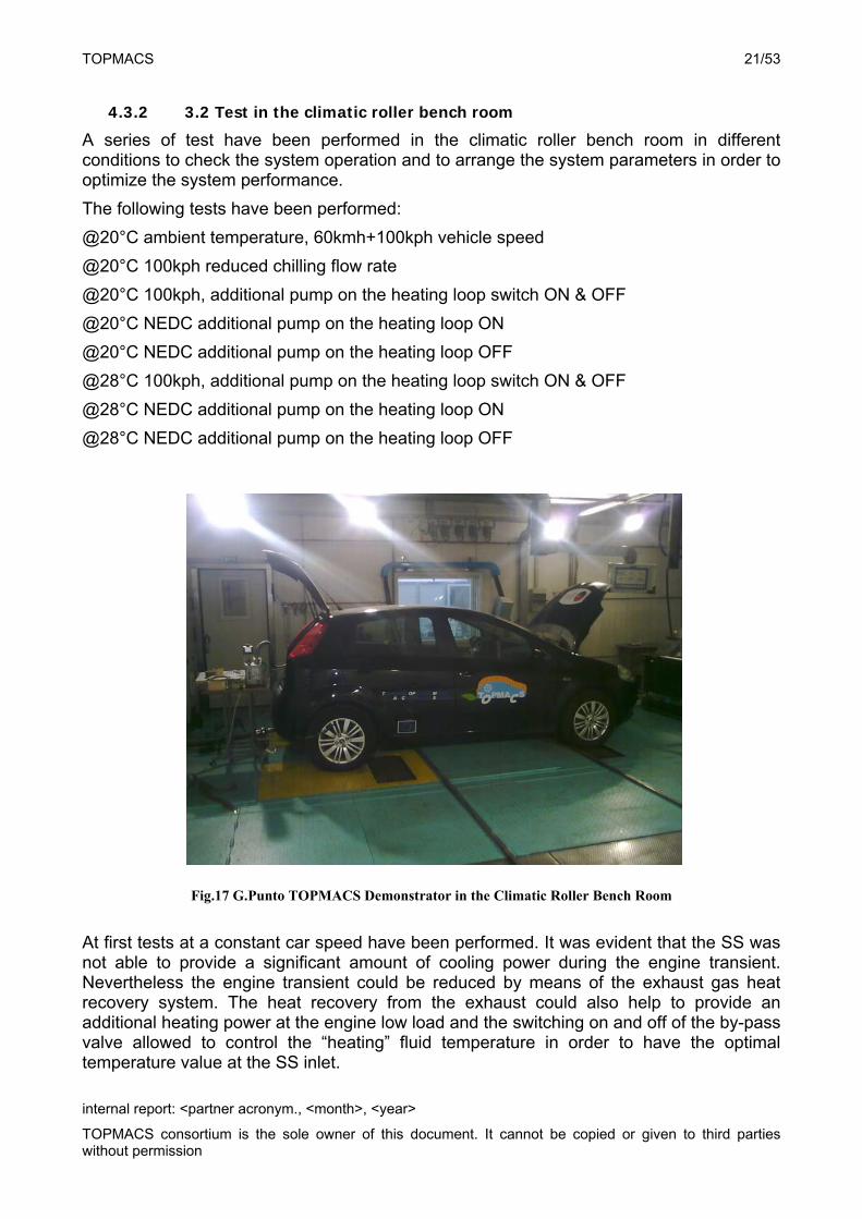
Fig.17 G.Punto TOPMACS Demonstrator in the Climatic Roller Bench Room
At first tests at a constant car speed have been performed. It was evident that the SS was not able to provide a significant amount of cooling power during the engine transient. Nevertheless the engine transient could be reduced by means of the exhaust gas heat recovery system. The heat recovery from the exhaust could also help to provide an additional heating power at the engine low load and the switching on and off of the by-pass valve allowed to control the “heating” fluid temperature in order to have the optimal temperature value at the SS inlet.
TOPMACS 22/53
internal report: <partner acronym., <month>, <year>
TOPMACS consortium is the sole owner of this document. It cannot be copied or given to third parties without permission
Moreover the system could be coupled with an auxiliary fuel burner (already used on Diesel engine car to improve the cabin heating in winter conditions). In this case The SS could be operated with the car engine stop providing also preconditioning function and allowing the system peak cooling power downsizing.
Tests have been performed changing the fluid flow rate in the chilling circuit. It has been found an improvement in the system performance reducing the 8lpm setpoint flow rate to 6lpm.
The fluid flow rate in the heating circuit is given by the engine coolant mechanical pump which depends on the engine speed and the additional electric pump. Tests have been performed switching on and off the additional pump and it has been proven the performance can be better obtained without the additional pump.
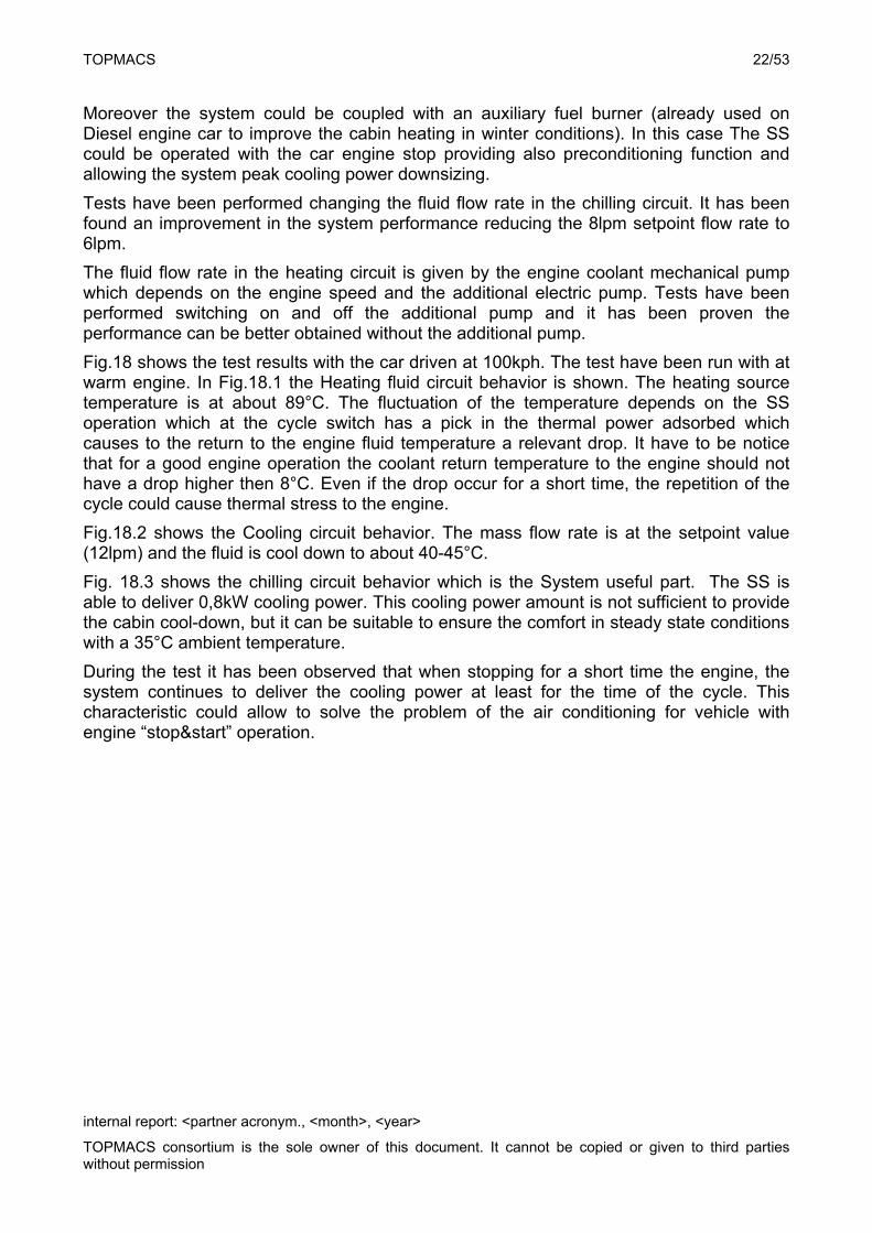
Fig.18 shows the test results with the car driven at 100kph. The test have been run with at warm engine. In Fig.18.1 the Heating fluid circuit behavior is shown. The heating source temperature is at about 89°C. The fluctuation of the temperature depends on the SS operation which at the cycle switch has a pick in the thermal power adsorbed which causes to the return to the engine fluid temperature a relevant drop. It have to be notice that for a good engine operation the coolant return temperature to the engine should not have a drop higher then 8°C. Even if the drop occur for a short time, the repetition of the cycle could cause thermal stress to the engine.
Fig.18.2 shows the Cooling circuit behavior. The mass flow rate is at the setpoint value (12lpm) and the fluid is cool down to about 40-45°C.
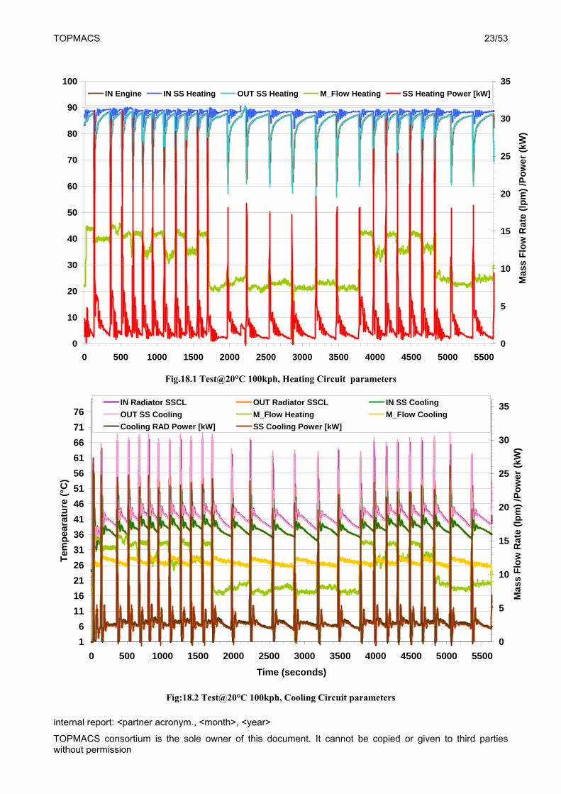
Fig. 18.3 shows the chilling circuit behavior which is the System useful part. The SS is able to deliver 0,8kW cooling power. This cooling power amount is not sufficient to provide the cabin cool-down, but it can be suitable to ensure the comfort in steady state conditions with a 35°C ambient temperature.
During the test it has been observed that when stopping for a short time the engine, the system continues to deliver the cooling power at least for the time of the cycle. This characteristic could allow to solve the problem of the air conditioning for vehicle with engine “stop&start” operation.
TOPMACS 23/53
internal report: <partner acronym., <month>, <year>
TOPMACS consortium is the sole owner of this document. It cannot be copied or given to third parties without permission
0
10
20
30
40
50
60
70
80
90
100
0 500 1000 1500 2000 2500 3000 3500 4000 4500 5000 5500
0
5
10
15
20
25
30
35IN Engine IN SS Heating OUT SS Heating M_Flow Heating SS Heating Power [kW]
Ma
ss F
low
Ra
te (
lpm
) /P
ow
er (
kW
)
Fig.18.1 Test@20°C 100kph, Heating Circuit parameters
1
6
11
16
21
26
31
36
41
46
51
56
61
66
71
76
0 500 1000 1500 2000 2500 3000 3500 4000 4500 5000 5500
Time (seconds)
Tem
pe
arat
ure
(°C
)
0
5
10
15
20
25
30
35IN Radiator SSCL OUT Radiator SSCL IN SS Cooling
OUT SS Cooling M_Flow Heating M_Flow Cooling
Cooling RAD Power [kW] SS Cooling Power [kW]
Mas
s F
low
Rat
e (l
pm
) /P
ow
er (
kW)
Fig:18.2 Test@20°C 100kph, Cooling Circuit parameters
TOPMACS 24/53
internal report: <partner acronym., <month>, <year>
TOPMACS consortium is the sole owner of this document. It cannot be copied or given to third parties without permission
0
2
4
6
8
10
12
14
16
18
20
22
24
26
28
0 500 1000 1500 2000 2500 3000 3500 4000 4500 5000 5500Time (seconds)
Tem
per
atu
re (
°C)
0
1
2
3
4
5
6
7
8
9
10
IN Cabin Cooler OUT Cabin Cooler IN SS Chilling
OUT SS Chilling Cabin Cooler Power [kW] M_Flow Chilling
SS Chilling Power [kW]
Mas
s F
low
Ra
te (
lpm
) /P
ow
er (
kW
)
Fig. 18.3 test@20°C 100kph, Chilling Circuit parameters
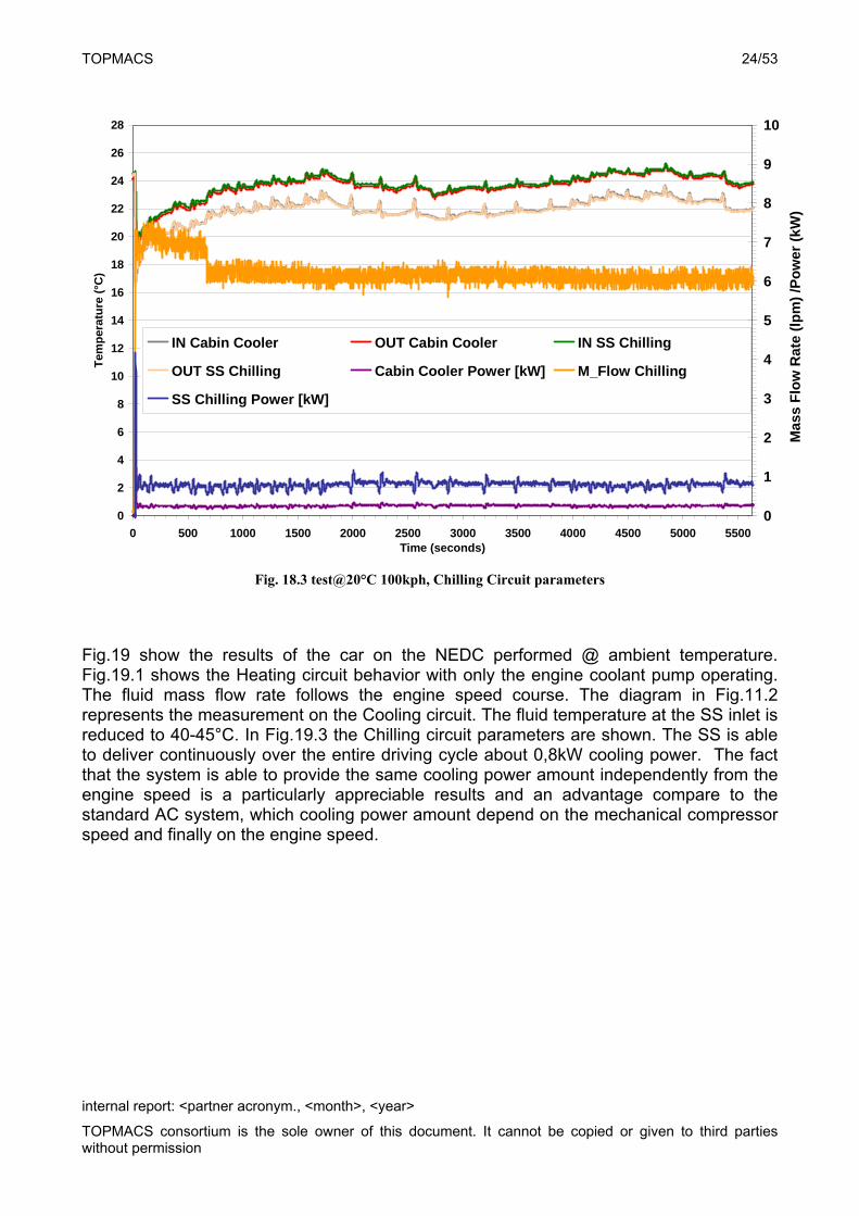
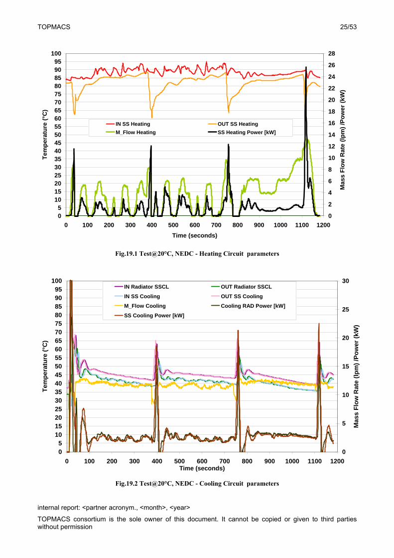
Fig.19 show the results of the car on the NEDC performed @ ambient temperature. Fig.19.1 shows the Heating circuit behavior with only the engine coolant pump operating. The fluid mass flow rate follows the engine speed course. The diagram in Fig.11.2 represents the measurement on the Cooling circuit. The fluid temperature at the SS inlet is reduced to 40-45°C. In Fig.19.3 the Chilling circuit parameters are shown. The SS is able to deliver continuously over the entire driving cycle about 0,8kW cooling power. The fact that the system is able to provide the same cooling power amount independently from the engine speed is a particularly appreciable results and an advantage compare to the standard AC system, which cooling power amount depend on the mechanical compressor speed and finally on the engine speed.
TOPMACS 25/53
internal report: <partner acronym., <month>, <year>
TOPMACS consortium is the sole owner of this document. It cannot be copied or given to third parties without permission
05
101520253035404550556065707580859095
100
0 100 200 300 400 500 600 700 800 900 1000 1100 1200
Time (seconds)
Tem
per
atu
re (
°C)
0
2
4
6
8
10
12
14
16
18
20
22
24
26
28
IN SS Heating OUT SS Heating
M_Flow Heating SS Heating Power [kW]
Mas
s F
low
Rat
e (l
pm
) /P
ow
er (
kW)
Fig.19.1 Test@20°C, NEDC - Heating Circuit parameters
05
101520253035404550556065707580859095
100
0 100 200 300 400 500 600 700 800 900 1000 1100 1200Time (seconds)
Tem
per
atu
re (
°C)
0
5
10
15
20
25
30IN Radiator SSCL OUT Radiator SSCL
IN SS Cooling OUT SS Cooling
M_Flow Cooling Cooling RAD Power [kW]
SS Cooling Power [kW]
Mas
s F
low
Rat
e (l
pm
) /P
ow
er (
kW)
Fig.19.2 Test@20°C, NEDC - Cooling Circuit parameters
TOPMACS 26/53
internal report: <partner acronym., <month>, <year>
TOPMACS consortium is the sole owner of this document. It cannot be copied or given to third parties without permission
02468
10121416182022242628303234363840
0 100 200 300 400 500 600 700 800 900 1000 1100 1200
Time (seconds)
Tem
pe
ratu
re (
°C)
0
1
2
3
4
5
6
7
8
9
10
IN Cabin Cooler OUT Cabin Cooler
IN SS Chilling OUT SS Chilling
M_Flow Chilling SS Chilling Power [kW]
Cabin Cooler Power [kW]
Mas
s F
low
Ra
te (
lpm
) /P
ow
er (
kW)
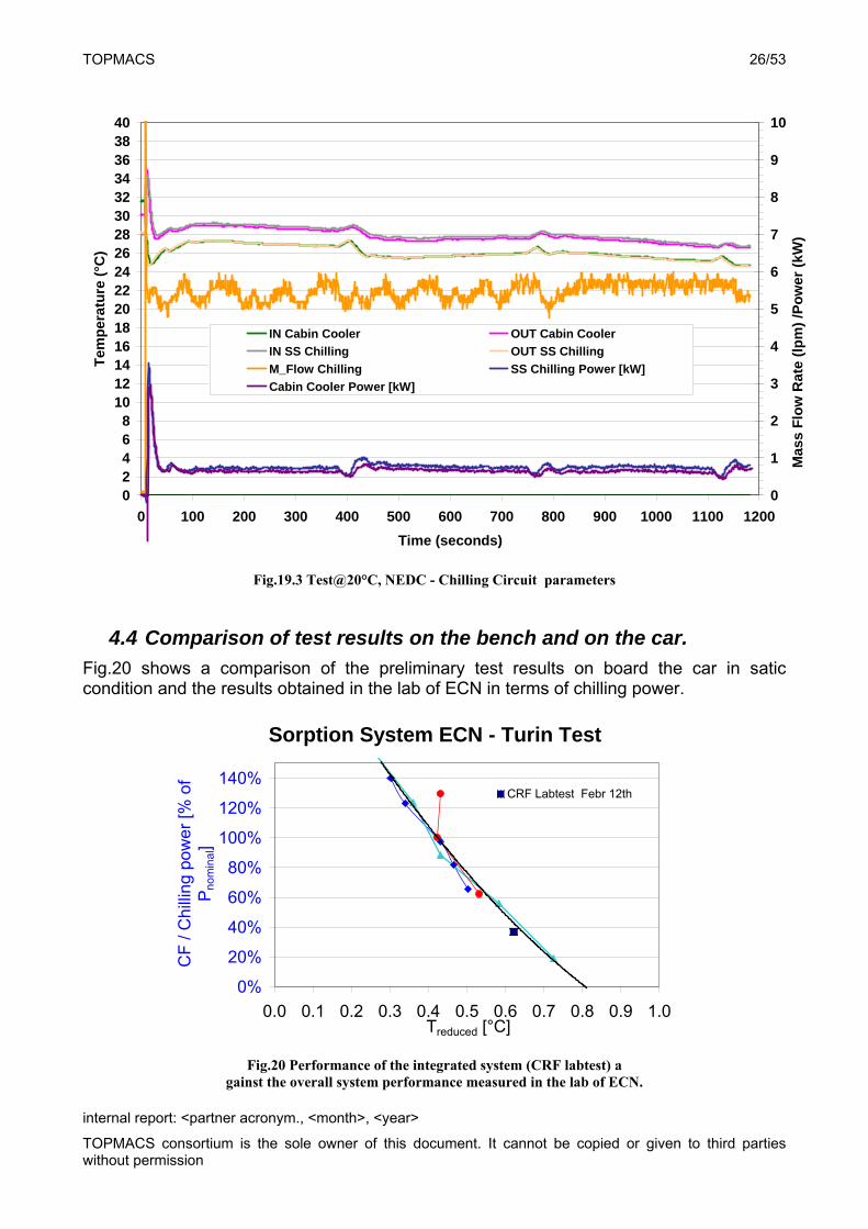
Fig.19.3 Test@20°C, NEDC - Chilling Circuit parameters
4.4 Comparison of test results on the bench and on the car.
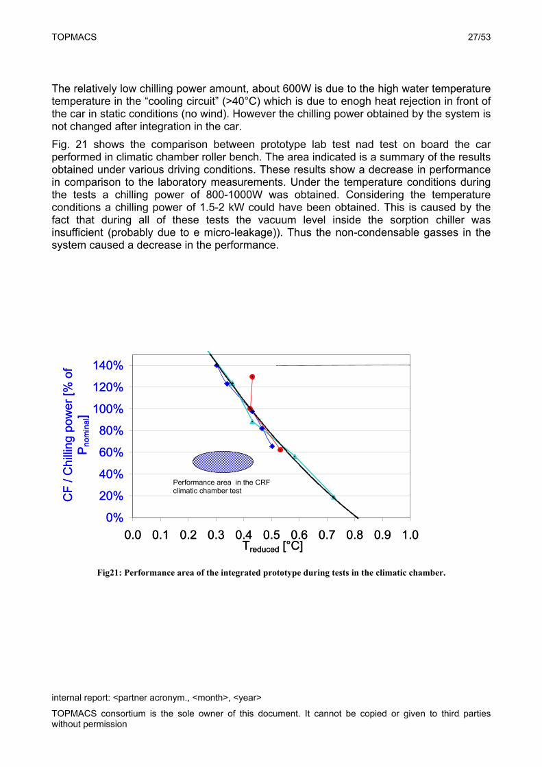
Fig.20 shows a comparison of the preliminary test results on board the car in satic condition and the results obtained in the lab of ECN in terms of chilling power.
Sorption System ECN - Turin Test
0%
20%
40%
60%
80%
100%
120%
140%
0.0 0.1 0.2 0.3 0.4 0.5 0.6 0.7 0.8 0.9 1.0Treduced [°C]
CF
/ C
hilli
ng p
owe
r [%
of
Pn
om
ina
l]
CRF Labtest Febr 12th
Fig.20 Performance of the integrated system (CRF labtest) a
gainst the overall system performance measured in the lab of ECN.
TOPMACS 27/53
internal report: <partner acronym., <month>, <year>
TOPMACS consortium is the sole owner of this document. It cannot be copied or given to third parties without permission
The relatively low chilling power amount, about 600W is due to the high water temperature temperature in the “cooling circuit” (>40°C) which is due to enogh heat rejection in front of the car in static conditions (no wind). However the chilling power obtained by the system is not changed after integration in the car.
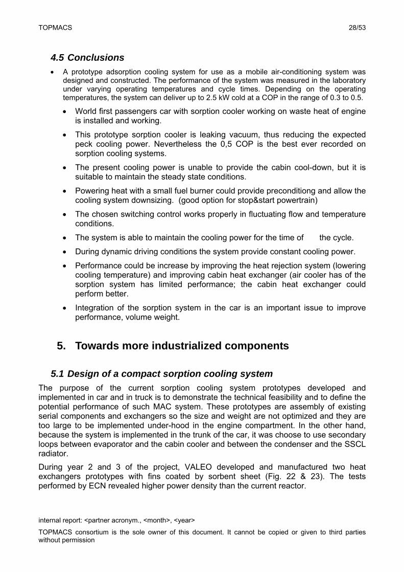
Fig. 21 shows the comparison between prototype lab test nad test on board the car performed in climatic chamber roller bench. The area indicated is a summary of the results obtained under various driving conditions. These results show a decrease in performance in comparison to the laboratory measurements. Under the temperature conditions during the tests a chilling power of 800-1000W was obtained. Considering the temperature conditions a chilling power of 1.5-2 kW could have been obtained. This is caused by the fact that during all of these tests the vacuum level inside the sorption chiller was insufficient (probably due to e micro-leakage)). Thus the non-condensable gasses in the system caused a decrease in the performance.
0%
20%
40%
60%
80%
100%
120%
140%
0.0 0.1 0.2 0.3 0.4 0.5 0.6 0.7 0.8 0.9 1.0Treduced [°C]
CF
/ C
hill
ing p
ow
er
[% o
f P
nom
ina
l]
CRF climatic 20C NEDCQheatingOFF Qchl6 Febr 20th
0%
20%
40%
60%
80%
100%
120%
140%
0.0 0.1 0.2 0.3 0.4 0.5 0.6 0.7 0.8 0.9 1.0Treduced [°C]
CF
/ C
hill
ing p
ow
er
[% o
f P
nom
ina
l]
CRF climatic 20C NEDCQheatingOFF Qchl6 Febr 20th
Fig21: Performance area of the integrated prototype during tests in the climatic chamber.
Performance area in the CRF climatic chamber test
TOPMACS 28/53
internal report: <partner acronym., <month>, <year>
TOPMACS consortium is the sole owner of this document. It cannot be copied or given to third parties without permission
4.5 Conclusions
A prototype adsorption cooling system for use as a mobile air-conditioning system was designed and constructed. The performance of the system was measured in the laboratory under varying operating temperatures and cycle times. Depending on the operating temperatures, the system can deliver up to 2.5 kW cold at a COP in the range of 0.3 to 0.5.
World first passengers car with sorption cooler working on waste heat of engine is installed and working.
This prototype sorption cooler is leaking vacuum, thus reducing the expected peck cooling power. Nevertheless the 0,5 COP is the best ever recorded on sorption cooling systems.
The present cooling power is unable to provide the cabin cool-down, but it is suitable to maintain the steady state conditions.
Powering heat with a small fuel burner could provide preconditiong and allow the cooling system downsizing. (good option for stop&start powertrain)
The chosen switching control works properly in fluctuating flow and temperature conditions.
The system is able to maintain the cooling power for the time of the cycle.
During dynamic driving conditions the system provide constant cooling power.
Performance could be increase by improving the heat rejection system (lowering cooling temperature) and improving cabin heat exchanger (air cooler has of the sorption system has limited performance; the cabin heat exchanger could perform better.
Integration of the sorption system in the car is an important issue to improve performance, volume weight.
5. Towards more industrialized components
5.1 Design of a compact sorption cooling system
The purpose of the current sorption cooling system prototypes developed and implemented in car and in truck is to demonstrate the technical feasibility and to define the potential performance of such MAC system. These prototypes are assembly of existing serial components and exchangers so the size and weight are not optimized and they are too large to be implemented under-hood in the engine compartment. In the other hand, because the system is implemented in the trunk of the car, it was choose to use secondary loops between evaporator and the cabin cooler and between the condenser and the SSCL radiator.
During year 2 and 3 of the project, VALEO developed and manufactured two heat exchangers prototypes with fins coated by sorbent sheet (Fig. 22 & 23). The tests performed by ECN revealed higher power density than the current reactor.
TOPMACS 29/53
internal report: <partner acronym., <month>, <year>
TOPMACS consortium is the sole owner of this document. It cannot be copied or given to third parties without permission
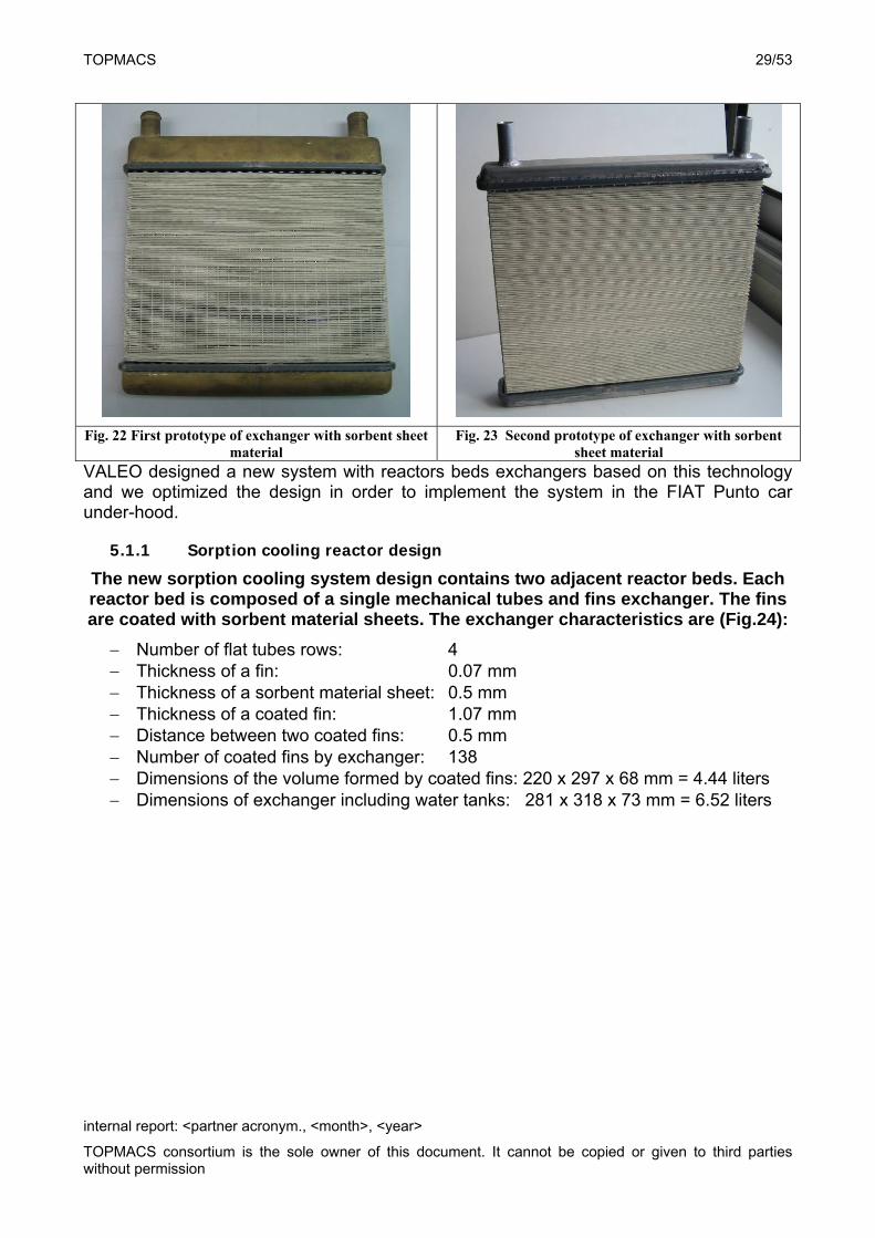
Fig. 22 First prototype of exchanger with sorbent sheet
material Fig. 23 Second prototype of exchanger with sorbent
sheet material VALEO designed a new system with reactors beds exchangers based on this technology and we optimized the design in order to implement the system in the FIAT Punto car under-hood.
5.1.1 Sorption cooling reactor design
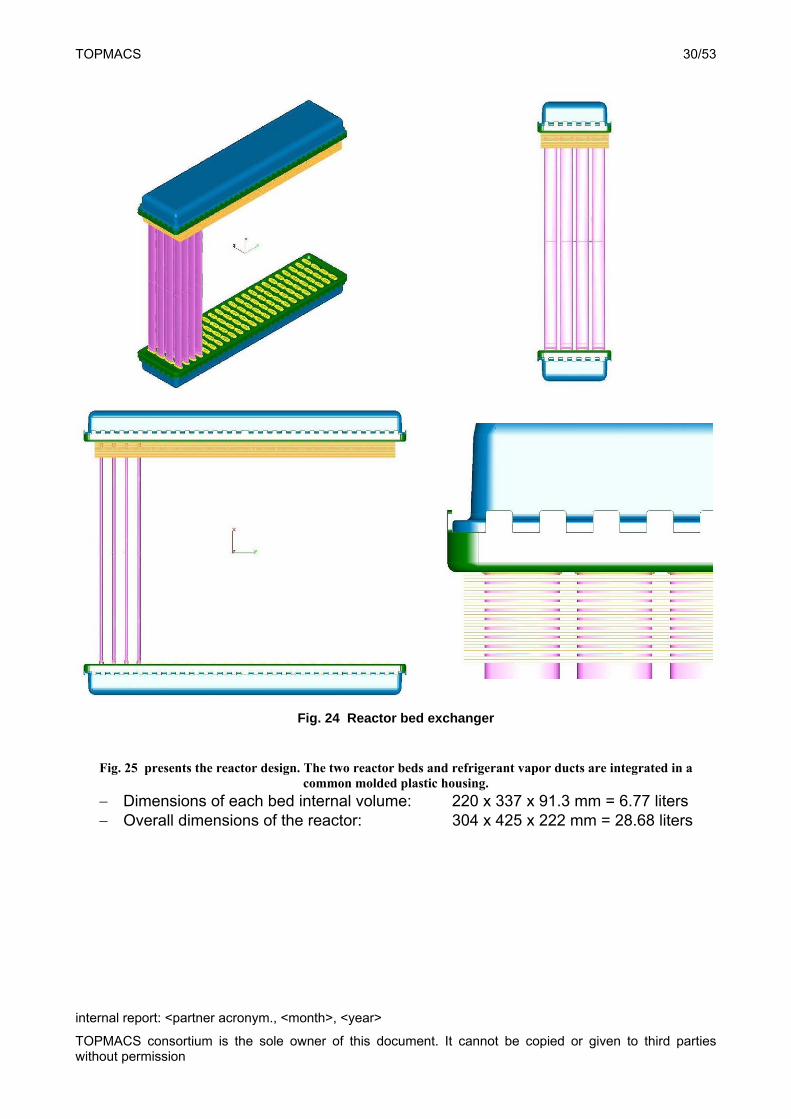
The new sorption cooling system design contains two adjacent reactor beds. Each reactor bed is composed of a single mechanical tubes and fins exchanger. The fins are coated with sorbent material sheets. The exchanger characteristics are (Fig.24):
Number of flat tubes rows: 4 Thickness of a fin: 0.07 mm Thickness of a sorbent material sheet: 0.5 mm Thickness of a coated fin: 1.07 mm Distance between two coated fins: 0.5 mm Number of coated fins by exchanger: 138 Dimensions of the volume formed by coated fins: 220 x 297 x 68 mm = 4.44 liters Dimensions of exchanger including water tanks: 281 x 318 x 73 mm = 6.52 liters
TOPMACS 30/53
internal report: <partner acronym., <month>, <year>
TOPMACS consortium is the sole owner of this document. It cannot be copied or given to third parties without permission
Fig. 24 Reactor bed exchanger
Fig. 25 presents the reactor design. The two reactor beds and refrigerant vapor ducts are integrated in a common molded plastic housing.
Dimensions of each bed internal volume: 220 x 337 x 91.3 mm = 6.77 liters Overall dimensions of the reactor: 304 x 425 x 222 mm = 28.68 liters
TOPMACS 31/53
internal report: <partner acronym., <month>, <year>
TOPMACS consortium is the sole owner of this document. It cannot be copied or given to third parties without permission
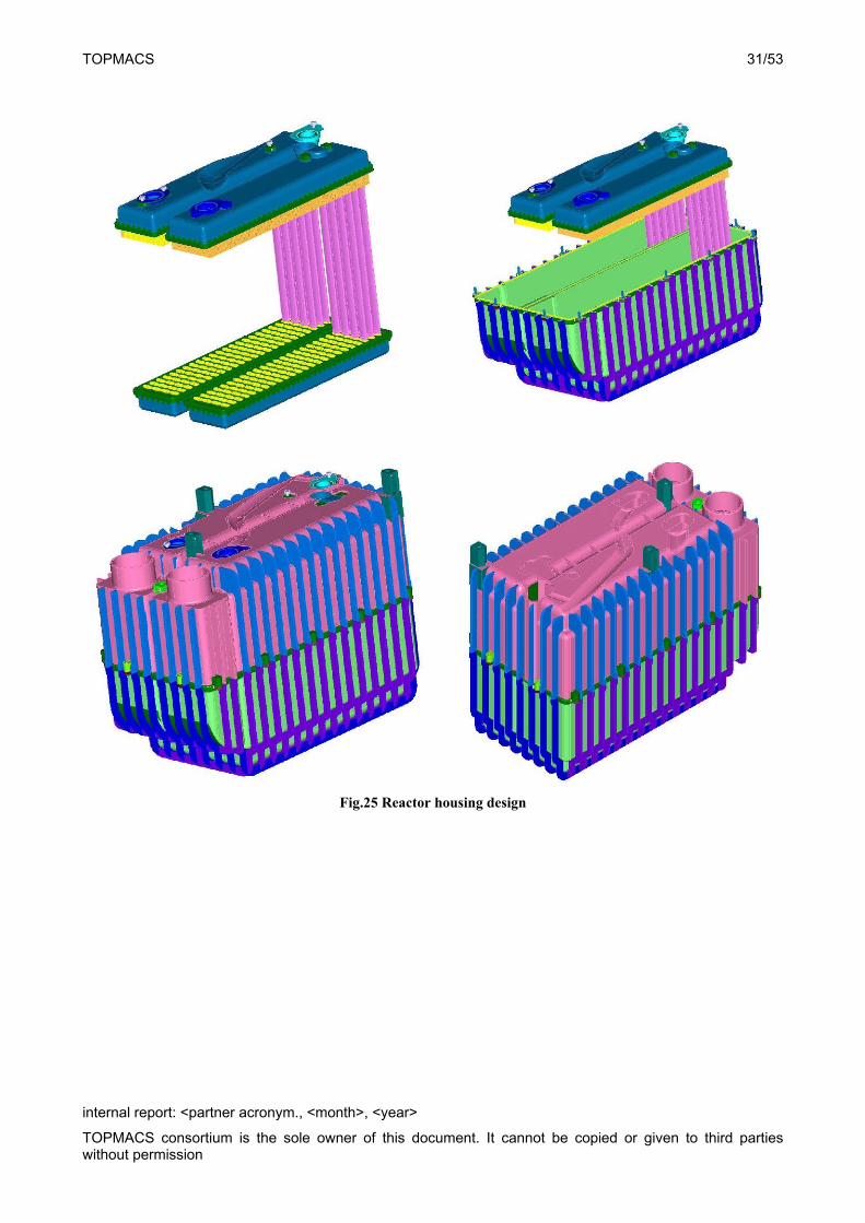
Fig.25 Reactor housing design
TOPMACS 32/53
internal report: <partner acronym., <month>, <year>
TOPMACS consortium is the sole owner of this document. It cannot be copied or given to third parties without permission
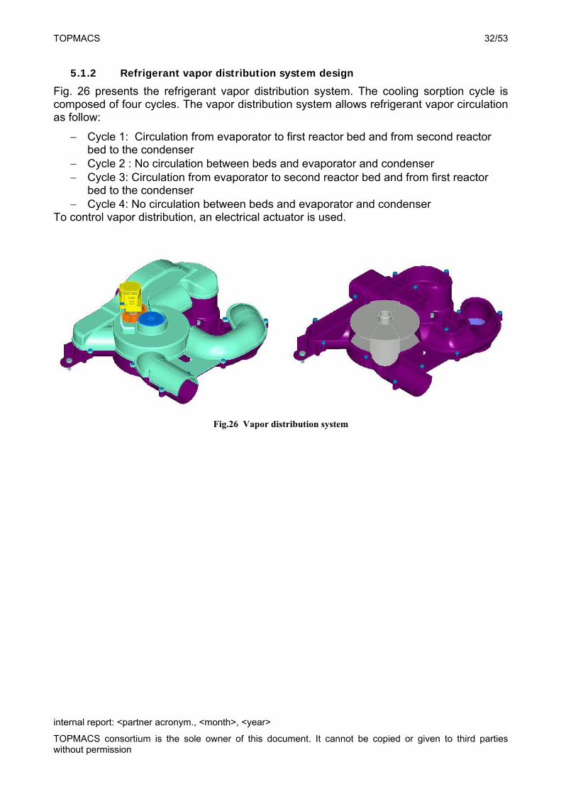
5.1.2 Refrigerant vapor distribution system design
Fig. 26 presents the refrigerant vapor distribution system. The cooling sorption cycle is composed of four cycles. The vapor distribution system allows refrigerant vapor circulation as follow:
Cycle 1: Circulation from evaporator to first reactor bed and from second reactor bed to the condenser
Cycle 2 : No circulation between beds and evaporator and condenser Cycle 3: Circulation from evaporator to second reactor bed and from first reactor
bed to the condenser Cycle 4: No circulation between beds and evaporator and condenser
To control vapor distribution, an electrical actuator is used.
Fig.26 Vapor distribution system
TOPMACS 33/53
internal report: <partner acronym., <month>, <year>
TOPMACS consortium is the sole owner of this document. It cannot be copied or given to third parties without permission
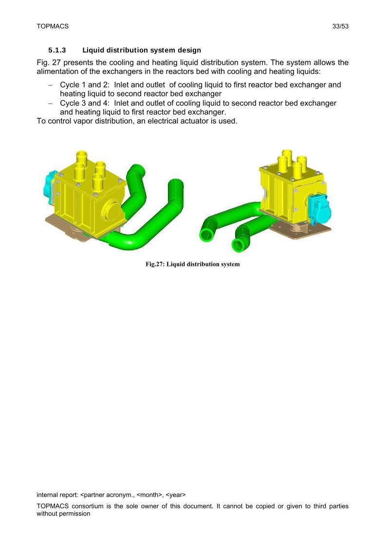
5.1.3 Liquid distribution system design
Fig. 27 presents the cooling and heating liquid distribution system. The system allows the alimentation of the exchangers in the reactors bed with cooling and heating liquids:
Cycle 1 and 2: Inlet and outlet of cooling liquid to first reactor bed exchanger and heating liquid to second reactor bed exchanger
Cycle 3 and 4: Inlet and outlet of cooling liquid to second reactor bed exchanger and heating liquid to first reactor bed exchanger.
To control vapor distribution, an electrical actuator is used.
Fig.27: Liquid distribution system
TOPMACS 34/53
internal report: <partner acronym., <month>, <year>
TOPMACS consortium is the sole owner of this document. It cannot be copied or given to third parties without permission
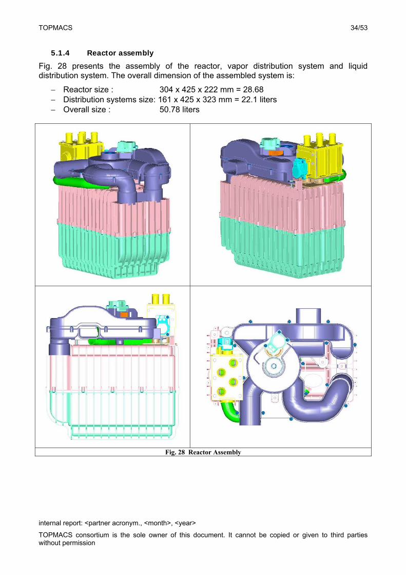
5.1.4 Reactor assembly
Fig. 28 presents the assembly of the reactor, vapor distribution system and liquid distribution system. The overall dimension of the assembled system is:
Reactor size : 304 x 425 x 222 mm = 28.68 Distribution systems size: 161 x 425 x 323 mm = 22.1 liters Overall size : 50.78 liters
Fig. 28 Reactor Assembly
TOPMACS 35/53
internal report: <partner acronym., <month>, <year>
TOPMACS consortium is the sole owner of this document. It cannot be copied or given to third parties without permission
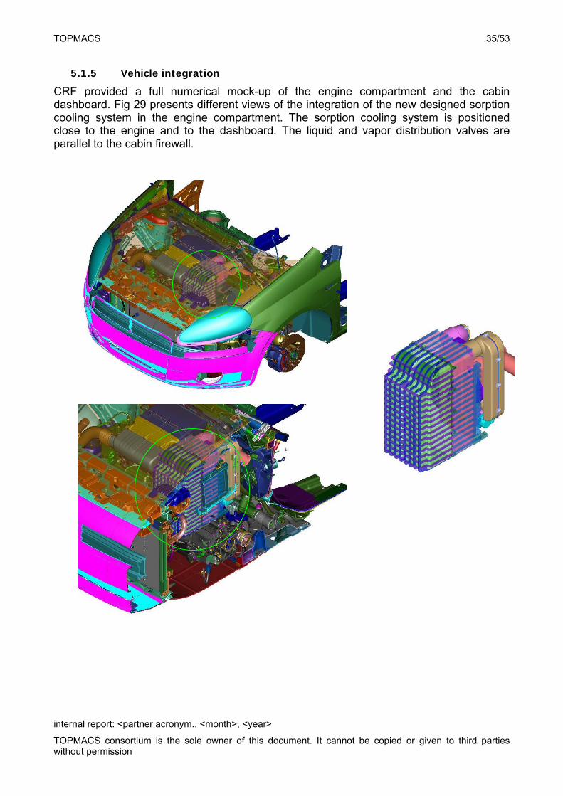
5.1.5 Vehicle integration
CRF provided a full numerical mock-up of the engine compartment and the cabin dashboard. Fig 29 presents different views of the integration of the new designed sorption cooling system in the engine compartment. The sorption cooling system is positioned close to the engine and to the dashboard. The liquid and vapor distribution valves are parallel to the cabin firewall.
TOPMACS 36/53
internal report: <partner acronym., <month>, <year>
TOPMACS consortium is the sole owner of this document. It cannot be copied or given to third parties without permission
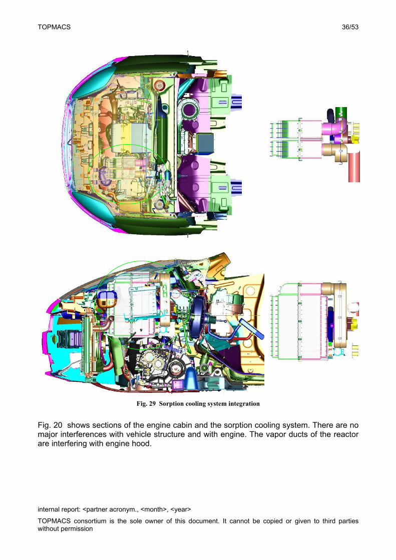
Fig. 29 Sorption cooling system integration
Fig. 20 shows sections of the engine cabin and the sorption cooling system. There are no major interferences with vehicle structure and with engine. The vapor ducts of the reactor are interfering with engine hood.
TOPMACS 37/53
internal report: <partner acronym., <month>, <year>
TOPMACS consortium is the sole owner of this document. It cannot be copied or given to third parties without permission
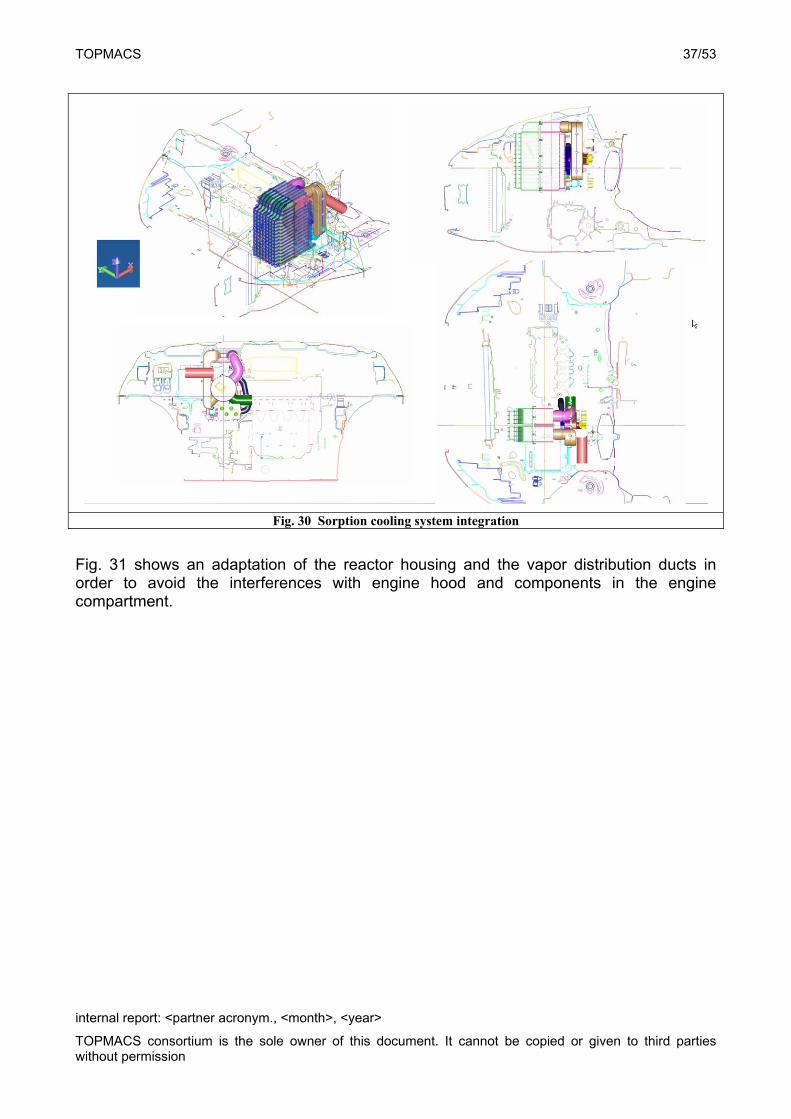
Fig. 30 Sorption cooling system integration
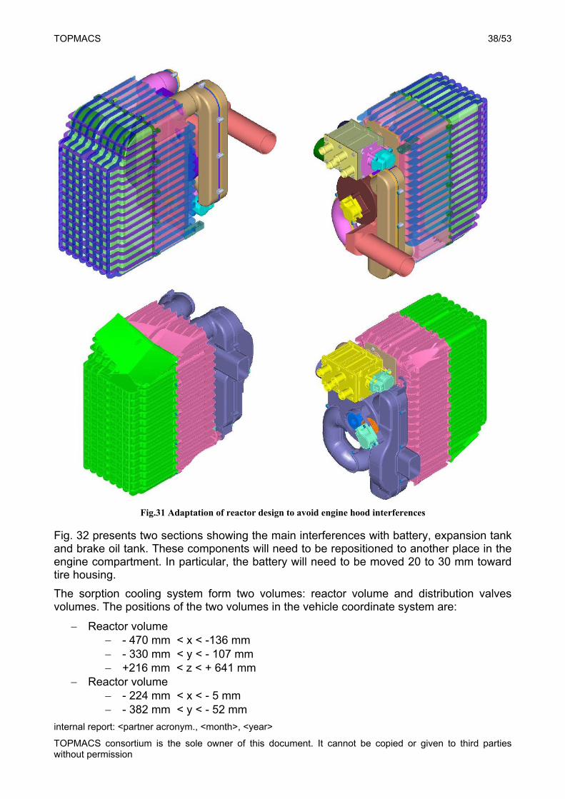
Fig. 31 shows an adaptation of the reactor housing and the vapor distribution ducts in order to avoid the interferences with engine hood and components in the engine compartment.
TOPMACS 38/53
internal report: <partner acronym., <month>, <year>
TOPMACS consortium is the sole owner of this document. It cannot be copied or given to third parties without permission
Fig.31 Adaptation of reactor design to avoid engine hood interferences
Fig. 32 presents two sections showing the main interferences with battery, expansion tank and brake oil tank. These components will need to be repositioned to another place in the engine compartment. In particular, the battery will need to be moved 20 to 30 mm toward tire housing.
The sorption cooling system form two volumes: reactor volume and distribution valves volumes. The positions of the two volumes in the vehicle coordinate system are:
Reactor volume - 470 mm < x < -136 mm - 330 mm < y < - 107 mm +216 mm < z < + 641 mm
Reactor volume - 224 mm < x < - 5 mm - 382 mm < y < - 52 mm
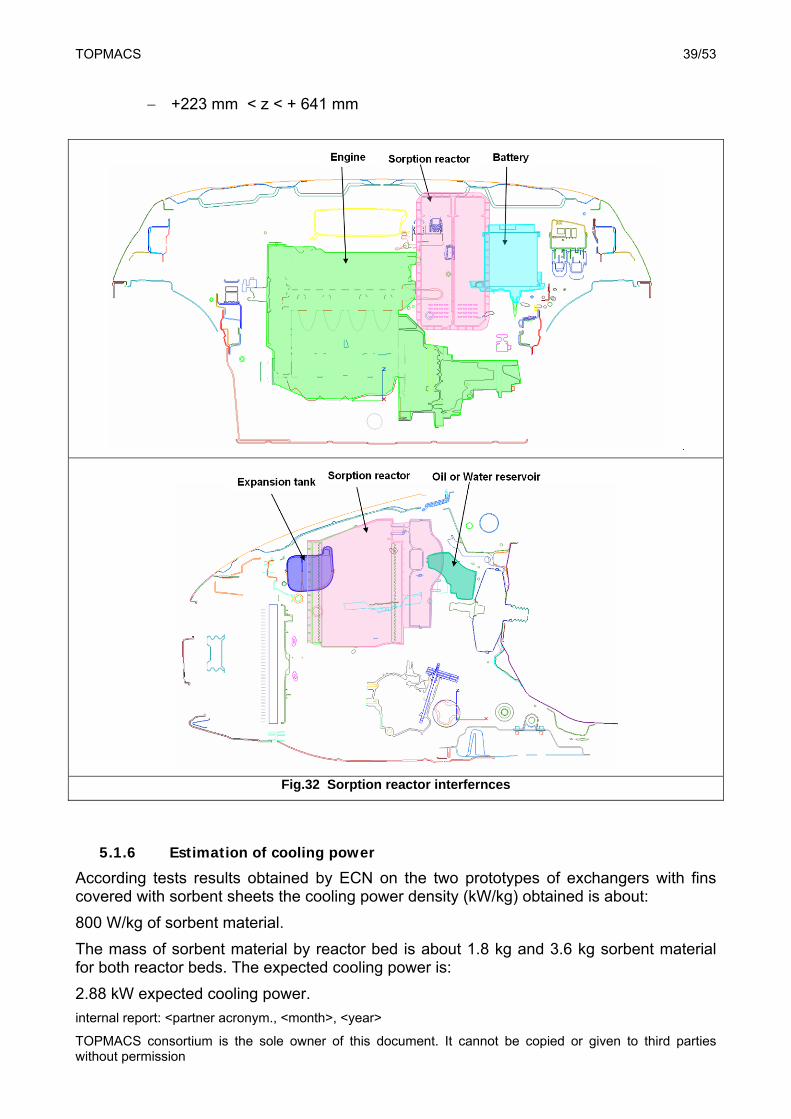
TOPMACS 39/53
internal report: <partner acronym., <month>, <year>
TOPMACS consortium is the sole owner of this document. It cannot be copied or given to third parties without permission
+223 mm < z < + 641 mm
Fig.32 Sorption reactor interfernces
5.1.6 Estimation of cooling power
According tests results obtained by ECN on the two prototypes of exchangers with fins covered with sorbent sheets the cooling power density (kW/kg) obtained is about:
800 W/kg of sorbent material.
The mass of sorbent material by reactor bed is about 1.8 kg and 3.6 kg sorbent material for both reactor beds. The expected cooling power is:
2.88 kW expected cooling power.
TOPMACS 40/53
internal report: <partner acronym., <month>, <year>
TOPMACS consortium is the sole owner of this document. It cannot be copied or given to third parties without permission
This cooling power is sufficient to ensure comfort in Normal ESC conditions (28°C 50%RH target 0.8 kW) and in severe ESC conditions (35°C 60% RH target 1.1 kW). However, this cooling power is not sufficient to satisfy the cabin cool down condition (target 4.0 kW).
The performance level of a sorbent coated heat exchanger claimed by UOP is 5 kW/kg of sorbent material. It indicates that it can still be possible to improve the cooling power density we may obtain with this technology. If we consider a potential cooling power density of 1.5 kW the cooling power of the system is about:
5.4 kW potential cooling power
6. Activated Carbon-Ammonia cooling system bench prototype
A second generation sorption cooling system based on the Carbon-Ammonia working pair has been designed, manufactured and bench tested at Warwick University. At 90oC (engine coolant water reference temperature) it was able to produced an average cooling power of 1.6 kW and a COP of about 0.2,3 under EU normal summer conditions (33oC and 20oC for ambient and cabin temperatures, respectively).
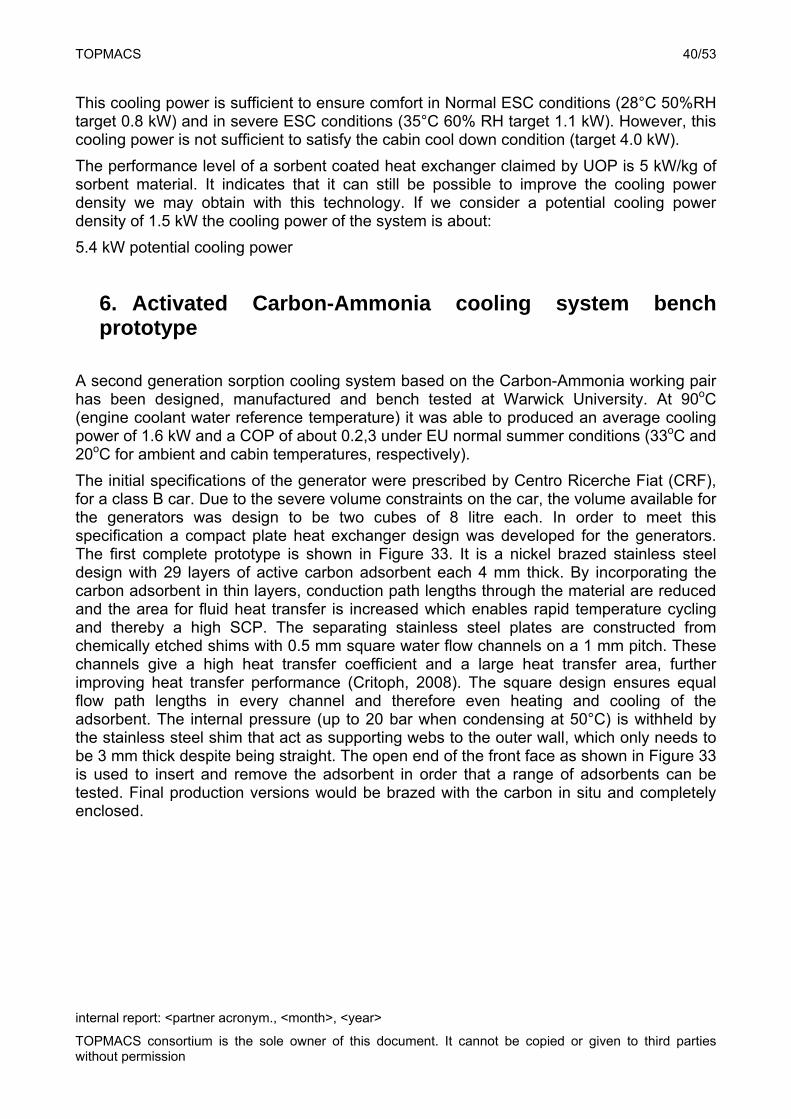
The initial specifications of the generator were prescribed by Centro Ricerche Fiat (CRF), for a class B car. Due to the severe volume constraints on the car, the volume available for the generators was design to be two cubes of 8 litre each. In order to meet this specification a compact plate heat exchanger design was developed for the generators. The first complete prototype is shown in Figure 33. It is a nickel brazed stainless steel design with 29 layers of active carbon adsorbent each 4 mm thick. By incorporating the carbon adsorbent in thin layers, conduction path lengths through the material are reduced and the area for fluid heat transfer is increased which enables rapid temperature cycling and thereby a high SCP. The separating stainless steel plates are constructed from chemically etched shims with 0.5 mm square water flow channels on a 1 mm pitch. These channels give a high heat transfer coefficient and a large heat transfer area, further improving heat transfer performance (Critoph, 2008). The square design ensures equal flow path lengths in every channel and therefore even heating and cooling of the adsorbent. The internal pressure (up to 20 bar when condensing at 50°C) is withheld by the stainless steel shim that act as supporting webs to the outer wall, which only needs to be 3 mm thick despite being straight. The open end of the front face as shown in Figure 33 is used to insert and remove the adsorbent in order that a range of adsorbents can be tested. Final production versions would be brazed with the carbon in situ and completely enclosed.
TOPMACS 41/53
internal report: <partner acronym., <month>, <year>
TOPMACS consortium is the sole owner of this document. It cannot be copied or given to third parties without permission
Fig.33 Plate heat exchanger generator design
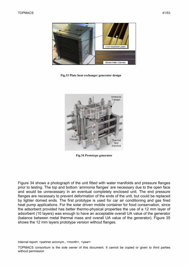
Fig.34 Prototype generator
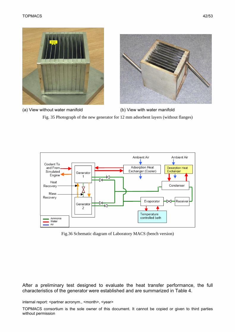
Figure 34 shows a photograph of the unit fitted with water manifolds and pressure flanges prior to testing. The top and bottom ‘ammonia flanges’ are necessary due to the open face and would be unnecessary in an eventual completely enclosed unit. The end pressure flanges are necessary to prevent deformation of the ends of the unit, but could be replaced by lighter domed ends. The first prototype is used for car air conditioning and gas fired heat pump applications. For the solar driven mobile container for food conservation, since the adsorbent provided has better thermo-physical properties the use of a 12 mm layer of adsorbent (10 layers) was enough to have an acceptable overall UA value of the generator (balance between metal thermal mass and overall UA value of the generator). Figure 35 shows the 12 mm layers prototype version without flanges.
TOPMACS 42/53
internal report: <partner acronym., <month>, <year>
TOPMACS consortium is the sole owner of this document. It cannot be copied or given to third parties without permission
(a) View without water manifold (b) View with water manifold
Fig. 35 Photograph of the new generator for 12 mm adsorbent layers (without flanges)
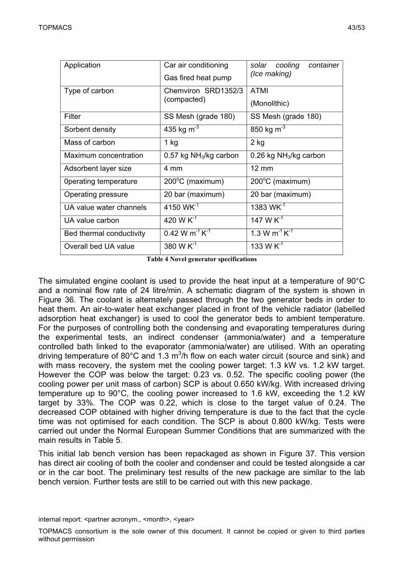
Fig.36 Schematic diagram of Laboratory MACS (bench version)
After a preliminary test designed to evaluate the heat transfer performance, the full characteristics of the generator were established and are summarized in Table 4.
TOPMACS 43/53
internal report: <partner acronym., <month>, <year>
TOPMACS consortium is the sole owner of this document. It cannot be copied or given to third parties without permission
Application Car air conditioning
Gas fired heat pump
solar cooling container (Ice making)
Type of carbon Chemviron SRD1352/3 (compacted)
ATMI
(Monolithic)
Filter SS Mesh (grade 180) SS Mesh (grade 180)
Sorbent density 435 kg m-3 850 kg m-3
Mass of carbon 1 kg 2 kg
Maximum concentration 0.57 kg NH3/kg carbon 0.26 kg NH3/kg carbon
Adsorbent layer size 4 mm 12 mm
0perating temperature 200oC (maximum) 200oC (maximum)
Operating pressure 20 bar (maximum) 20 bar (maximum)
UA value water channels 4150 WK-1 1383 WK-1
UA value carbon 420 W K-1 147 W K-1
Bed thermal conductivity 0.42 W m-1 K-1 1.3 W m-1 K-1
Overall bed UA value 380 W K-1 133 W K-1
Table 4 Novel generator specifications
The simulated engine coolant is used to provide the heat input at a temperature of 90°C and a nominal flow rate of 24 litre/min. A schematic diagram of the system is shown in Figure 36. The coolant is alternately passed through the two generator beds in order to heat them. An air-to-water heat exchanger placed in front of the vehicle radiator (labelled adsorption heat exchanger) is used to cool the generator beds to ambient temperature. For the purposes of controlling both the condensing and evaporating temperatures during the experimental tests, an indirect condenser (ammonia/water) and a temperature controlled bath linked to the evaporator (ammonia/water) are utilised. With an operating driving temperature of 80°C and 1.3 m3/h flow on each water circuit (source and sink) and with mass recovery, the system met the cooling power target: 1.3 kW vs. 1.2 kW target. However the COP was below the target: 0.23 vs. 0.52. The specific cooling power (the cooling power per unit mass of carbon) SCP is about 0.650 kW/kg. With increased driving temperature up to 90°C, the cooling power increased to 1.6 kW, exceeding the 1.2 kW target by 33%. The COP was 0.22, which is close to the target value of 0.24. The decreased COP obtained with higher driving temperature is due to the fact that the cycle time was not optimised for each condition. The SCP is about 0.800 kW/kg. Tests were carried out under the Normal European Summer Conditions that are summarized with the main results in Table 5.
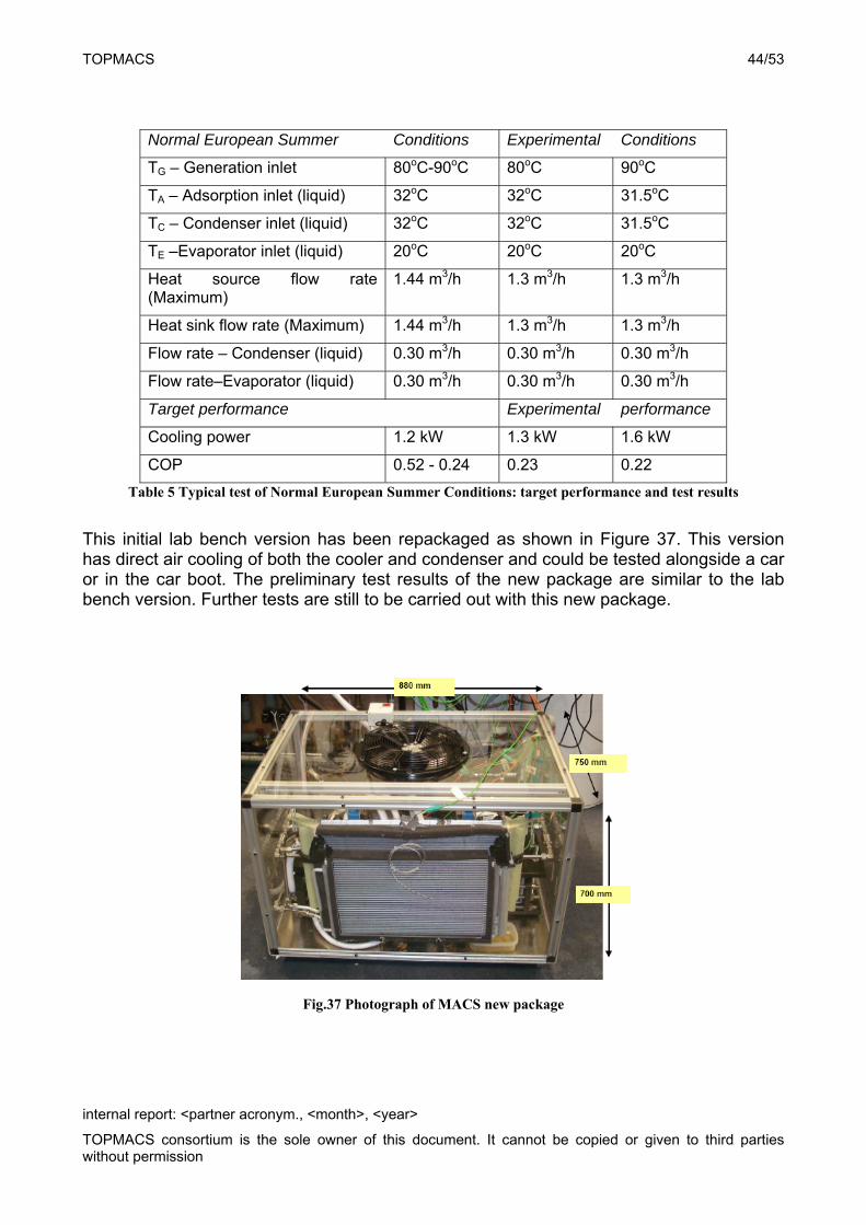
This initial lab bench version has been repackaged as shown in Figure 37. This version has direct air cooling of both the cooler and condenser and could be tested alongside a car or in the car boot. The preliminary test results of the new package are similar to the lab bench version. Further tests are still to be carried out with this new package.
TOPMACS 44/53
internal report: <partner acronym., <month>, <year>
TOPMACS consortium is the sole owner of this document. It cannot be copied or given to third parties without permission
Normal European Summer Conditions Experimental Conditions
TG – Generation inlet 80oC-90oC 80oC 90oC
TA – Adsorption inlet (liquid) 32oC 32oC 31.5oC
TC – Condenser inlet (liquid) 32oC 32oC 31.5oC
TE –Evaporator inlet (liquid) 20oC 20oC 20oC
Heat source flow rate (Maximum)
1.44 m3/h 1.3 m3/h 1.3 m3/h
Heat sink flow rate (Maximum) 1.44 m3/h 1.3 m3/h 1.3 m3/h
Flow rate – Condenser (liquid) 0.30 m3/h 0.30 m3/h 0.30 m3/h
Flow rate–Evaporator (liquid) 0.30 m3/h 0.30 m3/h 0.30 m3/h
Target performance Experimental performance
Cooling power 1.2 kW 1.3 kW 1.6 kW
COP 0.52 - 0.24 0.23 0.22
Table 5 Typical test of Normal European Summer Conditions: target performance and test results
This initial lab bench version has been repackaged as shown in Figure 37. This version has direct air cooling of both the cooler and condenser and could be tested alongside a car or in the car boot. The preliminary test results of the new package are similar to the lab bench version. Further tests are still to be carried out with this new package.
Fig.37 Photograph of MACS new package
TOPMACS 45/53
internal report: <partner acronym., <month>, <year>
TOPMACS consortium is the sole owner of this document. It cannot be copied or given to third parties without permission
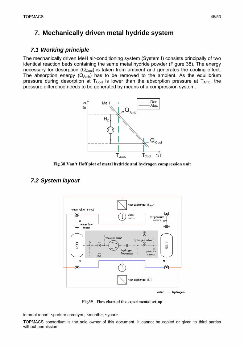
7. Mechanically driven metal hydride system
7.1 Working principle
The mechanically driven MeH air-conditioning system (System I) consists principally of two identical reaction beds containing the same metal hydride powder (Figure 38). The energy necessary for desorption (QCool) is taken from ambient and generates the cooling effect. The absorption energy (QAmb) has to be removed to the ambient. As the equilibrium pressure during desorption at TCool is lower than the absorption pressure at TAmb, the pressure difference needs to be generated by means of a compression system.
Fig.38 Van’t Hoff plot of metal hydride and hydrogen compression unit
7.2 System layout
Fig.39 Flow chart of the experimental set-up
TOPMACS 46/53
internal report: <partner acronym., <month>, <year>
TOPMACS consortium is the sole owner of this document. It cannot be copied or given to third parties without permission
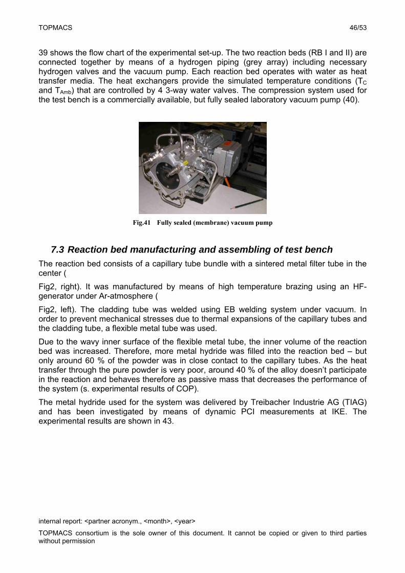
39 shows the flow chart of the experimental set-up. The two reaction beds (RB I and II) are connected together by means of a hydrogen piping (grey array) including necessary hydrogen valves and the vacuum pump. Each reaction bed operates with water as heat transfer media. The heat exchangers provide the simulated temperature conditions (TC and TAmb) that are controlled by 4 3-way water valves. The compression system used for the test bench is a commercially available, but fully sealed laboratory vacuum pump (40).
Fig.41 Fully sealed (membrane) vacuum pump
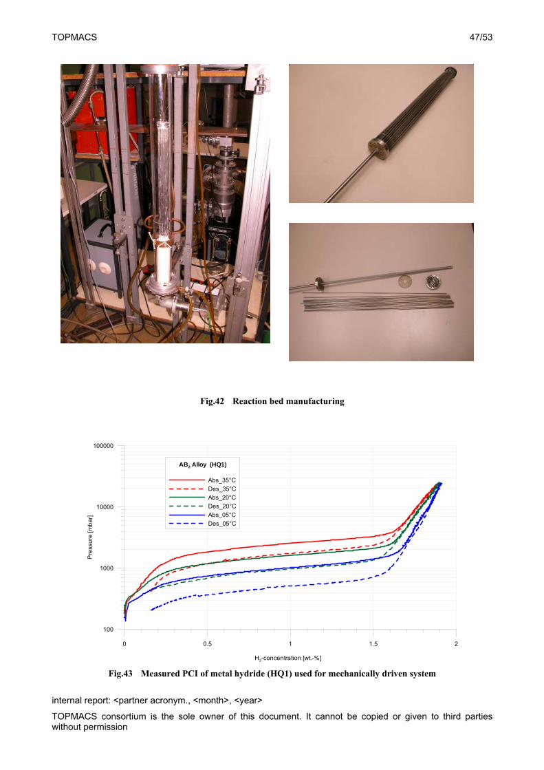
7.3 Reaction bed manufacturing and assembling of test bench
The reaction bed consists of a capillary tube bundle with a sintered metal filter tube in the center (
Fig2, right). It was manufactured by means of high temperature brazing using an HF-generator under Ar-atmosphere (
Fig2, left). The cladding tube was welded using EB welding system under vacuum. In order to prevent mechanical stresses due to thermal expansions of the capillary tubes and the cladding tube, a flexible metal tube was used.
Due to the wavy inner surface of the flexible metal tube, the inner volume of the reaction bed was increased. Therefore, more metal hydride was filled into the reaction bed – but only around 60 % of the powder was in close contact to the capillary tubes. As the heat transfer through the pure powder is very poor, around 40 % of the alloy doesn’t participate in the reaction and behaves therefore as passive mass that decreases the performance of the system (s. experimental results of COP).
The metal hydride used for the system was delivered by Treibacher Industrie AG (TIAG) and has been investigated by means of dynamic PCI measurements at IKE. The experimental results are shown in 43.
TOPMACS 47/53
internal report: <partner acronym., <month>, <year>
TOPMACS consortium is the sole owner of this document. It cannot be copied or given to third parties without permission
Fig.42 Reaction bed manufacturing
0 0.5 1 1.5 2
H2-concentration [wt.-%]
100
1000
10000
100000
Pre
ssu
re [m
ba
r]
AB2 Alloy (HQ1)
Abs_35°C
Des_35°C
Abs_20°C
Des_20°C
Abs_05°C
Des_05°C
Fig.43 Measured PCI of metal hydride (HQ1) used for mechanically driven system
TOPMACS 48/53
internal report: <partner acronym., <month>, <year>
TOPMACS consortium is the sole owner of this document. It cannot be copied or given to third parties without permission
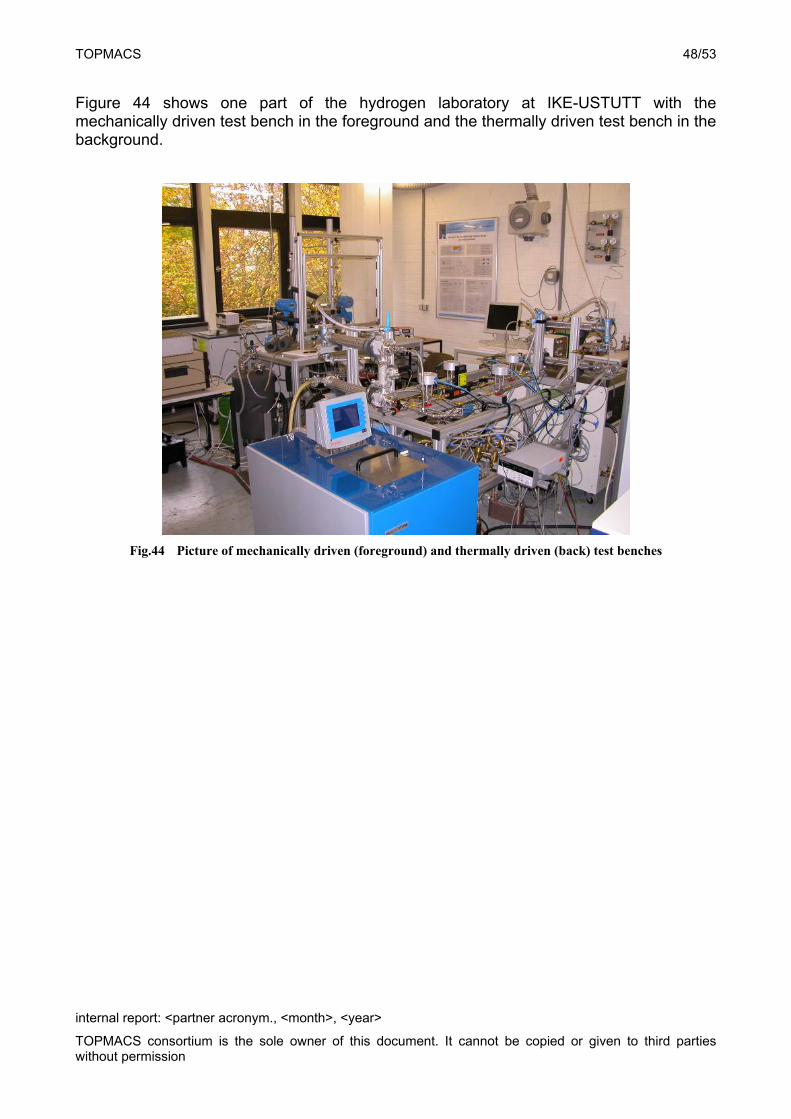
Figure 44 shows one part of the hydrogen laboratory at IKE-USTUTT with the mechanically driven test bench in the foreground and the thermally driven test bench in the background.
Fig.44 Picture of mechanically driven (foreground) and thermally driven (back) test benches
TOPMACS 49/53
internal report: <partner acronym., <month>, <year>
TOPMACS consortium is the sole owner of this document. It cannot be copied or given to third parties without permission
7.4 Experimental results The mechanically driven system has been experimentally investigated in order to understand the operation
characteristics and main influence factors on the performance of the system. Table gives an overview of the various performed experiments. The varied parameters are:
1. Half-cycle time,
2. Temperature boundary conditions,
3. Working pressures,
4. Water flow rates.
Water flow rate [l/min] Half-cycle time [s] TAmb [°C] TCool [°C]
6 100 28 15
6 150 28 15
6 200 28 15
6 250 28 15
6 100 35 20
6 150 35 20
6 200 35 20
6 250 35 20
6 210 28 20
6 210 28 15
6 210 28 10
6 210 35 20
6 210 35 15
6 210 35 10
6 210 43 20
6 210 43 15
6 210 43 10
6 210 35 20
6 210 45 30
6 210 55 40
2 210 28 15
4 210 28 15
6 210 28 15
2 210 35 20
4 210 35 20
6 210 35 20
Table 6 Summary of experimental test performed with mechanically driven system
TOPMACS 50/53
internal report: <partner acronym., <month>, <year>
TOPMACS consortium is the sole owner of this document. It cannot be copied or given to third parties without permission
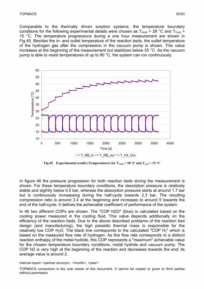
Comparable to the thermally driven sorption systems, the temperature boundary conditions for the following experimental details were chosen as TAmb = 28 °C and TCool = 15 °C. The temperature progressions during a one hour measurement are shown in Fig.45. Besides the in- and outlet temperature of the reaction beds, the outlet temperature of the hydrogen gas after the compression in the vacuum pump is shown. This value increases at the beginning of the measurement but stabilizes below 55 °C. As the vacuum pump is able to resist temperatures of up to 90 °C, the system can run continuously.
10
15
20
25
30
35
40
45
50
55
60
0 500 1000 1500 2000 2500 3000 3500 4000
Time [s]
Tem
pera
ture
[°C
]
T_RB_in T_RB_out T_H2_Out
Fig.45 Experimental results (Temperatures) for TAmb = 28 °C and Tcool = 15 °C
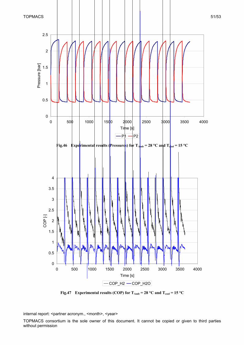
In figure 46 the pressure progression for both reaction beds during the measurement is shown. For these temperature boundary conditions, the desorption pressure is relatively stable and slgihtly below 0.5 bar, whereas the absorption pressure starts at around 1.7 bar but is continuously increaseing during the half-cycle towards 2.3 bar. The resulting compression ratio is around 3.4 at the beginning and increases to around 5 towards the end of the half-cycle. It defines the achievable coefficient of performance of the system.
In 46 two different COPs are shown. The "COP H2O" (blue) is calculated based on the cooling power measured in the cooling fluid. This value depends additionally on the efficiency of the reaction beds. Due to the above described problems of the reaction bed design (and manufacturing), the high parasitic thermal mass is responsible for the relatively low COP H2O. The black line corresponds to the calculated "COP H2" which is based on the measured flow rate of hydrogen. As this flow rate corresponds to a distinct reaction enthalpy of the metal hydride, this COP represents a "maximum" achievable value for the chosen temperature boundary conditions, metal hydride and vacuum pump. The COP H2 is very high at the beginning of the reaction and decreases towards the end; its average value is around 2.
TOPMACS 51/53
internal report: <partner acronym., <month>, <year>
TOPMACS consortium is the sole owner of this document. It cannot be copied or given to third parties without permission
0
0.5
1
1.5
2
2.5
0 500 1000 1500 2000 2500 3000 3500 4000
Time [s]
Pre
ssur
e [b
ar]
P1 P2
Fig.46 Experimental results (Pressures) for TAmb = 28 °C and Tcool = 15 °C
0
0.5
1
1.5
2
2.5
3
3.5
4
0 500 1000 1500 2000 2500 3000 3500 4000
Time [s]
CO
P [-
]
COP_H2 COP_H2O
Fig.47 Experimental results (COP) for TAmb = 28 °C and Tcool = 15 °C
TOPMACS 52/53
internal report: <partner acronym., <month>, <year>
TOPMACS consortium is the sole owner of this document. It cannot be copied or given to third parties without permission
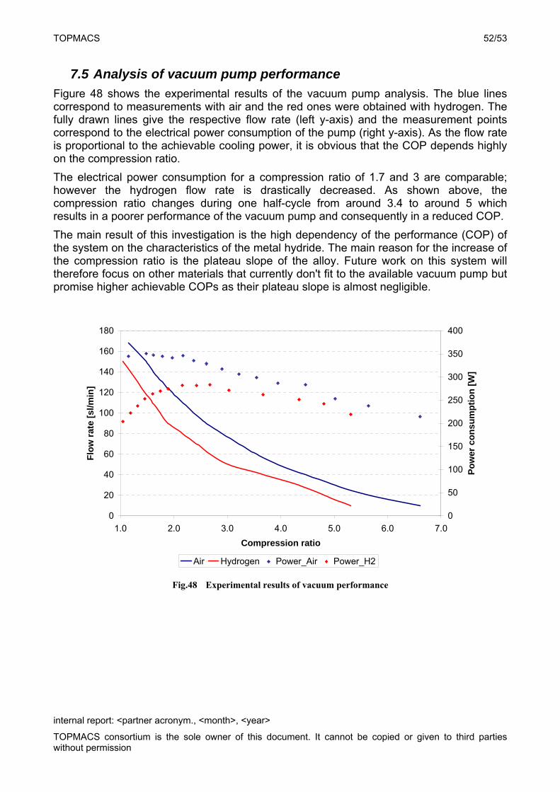
7.5 Analysis of vacuum pump performance
Figure 48 shows the experimental results of the vacuum pump analysis. The blue lines correspond to measurements with air and the red ones were obtained with hydrogen. The fully drawn lines give the respective flow rate (left y-axis) and the measurement points correspond to the electrical power consumption of the pump (right y-axis). As the flow rate is proportional to the achievable cooling power, it is obvious that the COP depends highly on the compression ratio.
The electrical power consumption for a compression ratio of 1.7 and 3 are comparable; however the hydrogen flow rate is drastically decreased. As shown above, the compression ratio changes during one half-cycle from around 3.4 to around 5 which results in a poorer performance of the vacuum pump and consequently in a reduced COP.
The main result of this investigation is the high dependency of the performance (COP) of the system on the characteristics of the metal hydride. The main reason for the increase of the compression ratio is the plateau slope of the alloy. Future work on this system will therefore focus on other materials that currently don't fit to the available vacuum pump but promise higher achievable COPs as their plateau slope is almost negligible.
0
20
40
60
80
100
120
140
160
180
1.0 2.0 3.0 4.0 5.0 6.0 7.0
Compression ratio
Flo
w r
ate
[sl/m
in]
0
50
100
150
200
250
300
350
400
Po
wer
co
nsu
mp
tio
n [
W]
Air Hydrogen Power_Air Power_H2
Fig.48 Experimental results of vacuum performance
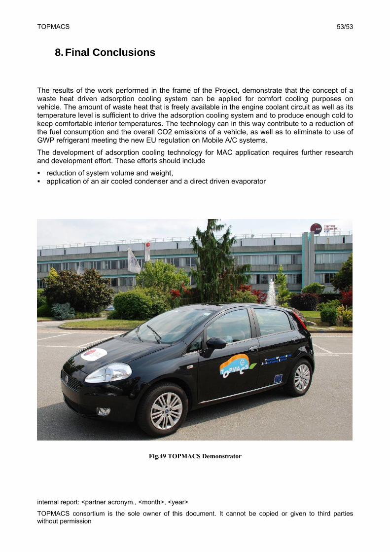
TOPMACS 53/53
internal report: <partner acronym., <month>, <year>
TOPMACS consortium is the sole owner of this document. It cannot be copied or given to third parties without permission
8. Final Conclusions
The results of the work performed in the frame of the Project, demonstrate that the concept of a waste heat driven adsorption cooling system can be applied for comfort cooling purposes on vehicle. The amount of waste heat that is freely available in the engine coolant circuit as well as its temperature level is sufficient to drive the adsorption cooling system and to produce enough cold to keep comfortable interior temperatures. The technology can in this way contribute to a reduction of the fuel consumption and the overall CO2 emissions of a vehicle, as well as to eliminate to use of GWP refrigerant meeting the new EU regulation on Mobile A/C systems.
The development of adsorption cooling technology for MAC application requires further research and development effort. These efforts should include
reduction of system volume and weight, application of an air cooled condenser and a direct driven evaporator
Fig.49 TOPMACS Demonstrator