Embed Size (px)
Citation preview

1
TOPOLOGY AND PARAMETRIC OPTIMIZATION OF A LATTICE COMPOSITE FUSELAGESTRUCTURE
OSVALDO M. QUERIN
School of Mechanical Engineering, University of Leeds,Leeds LS2 9JT, United Kingdom
VASSILI V. TOROPOV
Schools of Civil Engineering and Mechanical Engineering, University of Leeds,Leeds LS2 9JT, United Kingdom
DIANZI LIU
Schools of Civil Engineering and Mechanical Engineering, University of Leeds,Leeds LS2 9JT, United Kingdom
HEIKE LOHSE-BUSCH
Department Composite Design, Institute of Composite Structures and Adaptive Systems,German Aerospace Center (DLR), Braunschweig, Germany
CHRISTIAN HÜHNE
Department Composite Design, Institute of Composite Structures and Adaptive Systems,German Aerospace Center (DLR), Braunschweig, Germany
STEFFEN NIEMANN
Department Composite Design, Institute of Composite Structures and Adaptive Systems,German Aerospace Center (DLR), Braunschweig, Germany
BORIS KOLESNIKOV
Department Composite Design, Institute of Composite Structures and Adaptive Systems,German Aerospace Center (DLR), Braunschweig, Germany
Abstract
Conventional commercial aircraft fuselages use all-aluminium semi-monocoque structures where the skin carries the external loads, theinternal fuselage pressurization and is strengthen using frames and stringers. Environmental and economic issues force aircraft
designers to minimize weight and costs to keep air transport competitive and safe. But as metal designs have reached a high degree ofperfection, extraordinary weight and cost savings are unlikely in the future. Carbon composite materials combined with latticestructures and the use of topology optimization have the potential to offer such weight reductions. The EU FP7 project Advanced
Lattice Structures for Composite Airframes (ALaSCA) was started to investigate this.An anisogrid composite fuselage section was optimized using topology optimization with respect to weight and structural
performance. The fuselage was parameterised and then a detail optimization was carried out using Genetic Algorithms on a metamodel
generated with Genetic Programming from a 101 point Latin hypercube design of experiments. Two optimum lattice fuselage barrelswere obtained and verified with finite element simulations. The first was optimized for strength requirement, producing a light weighfuselage with few thin helical ribs and circumferential frames, and large skin bays. The second was optimized for strength, stability and
stiffness requirements, producing a heavier structure with smaller skin bays and more stiffeners, where stability became the driving
O. M. Querin, V. V. Toropov, D. Liu, H. Lohse-Busch, C. Hühne, S. Niemann, B. Kolesnikov2
criterion. It is concluded that the use of the global metamodel-based approach combined with topology optimization has allowed tosolve this optimization problem with sufficient accuracy as well as provided the designers with a wealth of information on the structuralbehaviour of the novel anisogrid composite fuselage design. This article presents this research which has now led to the development of
a new airframe concept.
Keywords Metamodel; anisogrid structure; Latin hypercube; topology optimization; Genetic programming; aircraft fuselage design.
1. Introduction
Conventional commercial aircraft fuselages use all-aluminium semi-monocoque structures, which exploit the
isotropic properties of the metal. The skin carries the external loads from the wings, empennage, engines, etc. as
well as the internal pressurization of the fuselage. The skin is then strengthened using a series of frames and
stringers which are either riveted or bonded [1]. These components are used to make large tubular sections,
which are then joined with fasteners to form the complete fuselage.
Environmental and economic issues force future aircraft designs to maximize efficiencies in weight and cost
to keep air transport competitive and safe. But as metal designs have reached a high degree of perfection,
extraordinary weight and cost savings are unlikely to be achieved in the future [2].
Carbon composites have high values of specific strength and rigidity, but the way in which they are currently
used only provide a weight savings of 10–20 % [3]. Carbon fibre reinforced plastics (CFRP) have a specific
strength 5 to 6 times higher and a specific rigidity 2-3 times higher than aluminium alloys [4]. The potential of
composites has therefore not been completely realized using conventional aircraft airframe layouts [5].
In the 1980s, the composite lattice structure was developed by the Russian Central Research Institute for
Special Machinery (CRISM) for rocket structures [6], Fig. 1 [7]. These structures consist of ribs either helically
or ring shaped made of unidirectional composites fibres using automatic filament winding, also known as
anisogrid structures. The skin of the cylindrical or conical shells is usually manufactured from carbon fabric
and only carries an insignificant part of the loading (tension, compression and shear). The high mechanical
properties of the unidirectional composites of the lattice ribs are the main factor for their high weight efficiency.
The automatic filament winding process ensures an integral structure with a low manufacturing cost. These
structures are most efficient if they are undisturbed, (i.e. without cut-outs etc.) and at present are therefore
predominantly applied in sections of space rockets [3].
Fig. 1. A typical composite lattice structure without the external skin
These experiences open up new opportunities for the optimization of composite aircraft fuselage barrels [2].
To determine this potential, a demonstrator was built as the DLR black fuselage concept [8, 9].
In order to address some of the issues associated with the implementation of composite lattice structure into
commercial aircraft, the EU FP7 project titled Advanced Lattice Structures for Composite Airframes (ALaSCA)
was started. This project consisted of carrying out a comprehensive investigation into the benefits of using the
geodesic composite lattice structures used in the rocket industry and transferring the technology to the design of
composite aircraft fuselages [10].
The aim of this article is to present the work carried out within the ALaSCA project which demonstrates that
the combined use of topology and parametric optimization becomes an integral tool for the design of composite
lattice aircraft fuselage barrel sections. The article presents: (1) the topology optimization problem, results and

Topology and Parametric Optimization of a Lattice Composite Fuselage Structure 3
their interpretation; (2) the different aspects of the primary composite lattice aircraft fuselage structure design,
(3) parametric optimization of the lattice composite fuselage structure using a metamodel-based optimization
technique, and (4) results and conclusions of this study.
2. Aircraft Configuration and Loads
This study used the aircraft configuration of the DLR funded project LamAiR, Fig. 2. The aim of that project
was to increase the technology readiness level of the laminar airflow technology for short and medium range
aircraft configurations [11].
The LamAiR aircraft configuration consists of a long fuselage barrel section mounted ahead of a forward
swept wing and rear mounted turbine engines. Since the passenger and cargo doors (large cut-outs) are in the
front cockpit-section or behind the wing, a long undisturbed barrel section can be designed as the main fuselage
section. A composite lattice structure, together with the use of topology optimization are ideally suited for this
type of configuration as it can lead to a light weight and cost efficient fuselage design. This configuration was
therefore used in this study.
The loads for the fuselage barrel were analysed with the Preliminary Aircraft Design and Optimization
(PrADO) program [12]. Four critical flight load cases were investigated and used to dimension the barrel. These
load cases were: (1) two gust load cases (vertical and lateral) at low altitude; (2) one gust load case (vertical and
lateral) at its maximum altitude and (3) a static internal pressure test load case whilst on the ground. Due to the
rear position of the wing, this type of fuselage configuration experiences higher loads than an equivalent
conventional swept back wing configuration
Fig. 2 The LamAiR aircraft configuration
3. Methodology for the Topology and Parametric Optimization of Aircraft Structures
The process of combining topology optimization with parametric optimization to effectively design a composite
lattice aircraft fuselage consists of six steps, these are:
1. Topology optimization
2. Topology extraction and simplification
3. Fuselage definition and design variable determination
4. Development of parameterized automatically generated finite element model
5. Generation of the metamodels
6. Optimization of the fuselage barrel using the metamodels
These eight stages in the new proposed process of aircraft fuselage design are explained in the next eight
sections of this article.

O. M. Querin, V. V. Toropov, D. Liu, H. Lohse-Busch, C. Hühne, S. Niemann, B. Kolesnikov4
4. Topology Optimization
The Solid Isotropic Material with Penalisation (SIMP) [13] topology optimization method was used to determine
the fuselage stiffener optimal orientation. This was achieved using Altair’s OptiStruct program [14] which has its
own finite element analysis solver.
The optimization problem consisted of minimizing the compliance of the fuselage section subject to the
applied loads. This optimization problem is given by Equation (1). Note that the buckling requirements were not
considered at this stage.
1
,...,1
tosubject
min
min
10
Nn
VV
CN
nnn
Tot
(1)
where: CTot is the total compliance for the structure, calculated using Equation (2) described in section 2.3; N
is the total number of finite elements in the designable part of the structure; n is the number of the analysed finite
element; is the design variable and artificial element density used by the SIMP method to optimize each finite
element in the structure. Since the fuselage skin thickness could vary from 30 mm (full stiffener present) down to
0.1 mm (only outer skin membrane present), the value of min used was 0.00333.Vn is the volume of the analysed
finite element and V0 is the maximum volume of the designable structure
4.1. Fuselage section
The length of the fuselage section selected was 13,652 mm, it included a load and support introduction bays,
both 399.8 mm in length. The rest of the fuselage had 23 bays with a 22” (558.8 mm) pitch, Fig. 3.
Fig. 3. Side view of the fuselage showing the different bays
The cross section was made from three different radii and included a passenger and a cargo floor with struts
connecting the two, Fig. 4.
Two different fuselage models were optimized, one with windows and one without. The model without
windows used 25,584 shell elements, 5,842 beam elements and one RBE2 element [14], making it a total of
31,427 FE, Fig. 7. The model which included windows used 25,100 shell elements, 5,842 beam elements and
one RBE2 element, making it a total of 30,943 FE, Fig. 8.
4.2. Applied loads
The loads applied were: a) distributed masses on the fuselage and its frames; b) point loads on the passenger and
cargo floors; and c) point loads and moments at the free end of the fuselage barrel section.

Topology and Parametric Optimization of a Lattice Composite Fuselage Structure 5
Fig. 4. Dimensioned cross-section of the fuselage section
There were five loads applied at the free end as three separate load cases, with the notation of Fig. 5. Load
case 1 consisted of a vertical shear force Qz = 211,711 N and moment My = 446,965 Nm. Load case 2 consisted
of a torque about the x axis applied in both directions, T = ±280 kNm. Load case 3 consisted of a horizontal
shear force Qy = ±80 kN and a bending moment Mz = 249,614 Nm applied in both directions. As part of Load
case 1, a 3.47 load factor was applied acting in the negative z direction on the mass of the fuselage and rings
present at the bay locations. The fuselage mass of 2,461.9 kg was evenly distributed over the entire fuselage and
the ring frames mass of 1322.8 kg was evenly distributed over the 23 rings. The passenger and cargo floor loads
shown in Fig. 6 had the magnitudes: FPassenger = 3238.5 N, FCC = 1510 N and FCL = 755 N.
Fig. 5. Fuselage section showing the loads applied at the free end
4.3. Optimization parameters
The fuselage was optimized for each load case individually. The compliance values of the optimal topologies for
the individual load cases were used to determine the multi-load weighting factors. These were used to calculate
the multi-load case compliance value of Equation (2), which was used to optimize all load cases applied
simultaneously. The logic behind this was that if the compliance value for the optimal topology of one of the
load cases was higher than the others, that particular load case was critical. Hence it should have a higher

O. M. Querin, V. V. Toropov, D. Liu, H. Lohse-Busch, C. Hühne, S. Niemann, B. Kolesnikov6
weighting in the total weighted compliance. The weighting factors for the fuselage without windows were: 1
=0.4483, 2 =0.1604,3 =0.3913, and with windows were: 1 =0.700, 2 = 0.252,3 = 0.048.
332211
3
1
ccccCLoad
LoadLoadTot
(2)
Fig. 6. Fuselage cross-section showing the passenger and cargo floor loads
4.4. Optimal layout of stiffeners
The fuselage section was optimised: 1) without windows, and 2) with windows. The results are given in Fig. 7
and Fig. 8 respectively.
5. Topology Extraction and Simplification
The results of Fig. 7 and 8 show two very distinctive features: 1) Substantially sized backbones on the upper and
lower extremities of the fuselage cross-section, and 2) Smaller rib-like stiffeners which start and end on the
backbones, and which criss-cross each other at different angles ranging from approximately 45° for fuselages
with windows and approximately 60° for fuselages without windows. The ideal stiffener arrangement would
therefore have continually varying angles, Fig. 9.
Such stiffeners are very complex and expensive to manufacture due to their continual varying sizes. As the
fuselage would be manufactured using the pultrusion [15] process, stiffeners with constant cross-section and
curvature are required. The design of Fig.9 was simplified accordingly by using stiffeners of constant angle
which were then aligned along geodesic lines on the fuselage skin, Fig. 10. This lattice structure generates non-
rectangular skin bays segments in a grid-like arrangement which considerably improves the buckling resistance
of the skin bays [17].
However, these grid stiffeners with very thin laminate thicknesses exhibit reduced axial stiffness when
compared to conventional stiffened panels. This is primarily due to the aircraft industry requirements for repair
and joining damage tolerance. To address this, a newly developed CFRP-metal-hybrid-material was used [18,
19]. The material has a high longitudinal stiffness because each CFRP unidirectional ply is bonded with a thin
steel foil. The CFRP-metal hybrid is then stacked to produce the required laminate thickness. A penalty of using
this material is that its density (1990 kg/m³) is 28% greater than conventional CFRP.

Topology and Parametric Optimization of a Lattice Composite Fuselage Structure 7
Fig. 7. Optimal stiffener layout for the fuselage without windows
Fig. 8. Optimal stiffener layout for the fuselage with windows

O. M. Querin, V. V. Toropov, D. Liu, H. Lohse-Busch, C. Hühne, S. Niemann, B. Kolesnikov8
Fig. 9. Fuselage barrel showing the continually varying angle stiffener arrangement
5.1. Selection of the grid stiffener configuration
Four grid stiffener concepts were analytically analysed using the barrel section dimensions of Fig. 3 with a 2.0 m
radius circular fuselage cross-section using standard beam theory, composite laminate theory and linear
buckling. The material used for the skin was Hexcel 8552/AS4 [16], it’s a CFRP with the following individual
ply properties: Young’s modulus E0° = 141 GPa, E90° = 10 GPa, density = 1550 kg/m³.
The four concepts were: (1) A conventional semi-monocoque with CFRP stiffeners and 1.625 mm skin
thickness; (2) A conventional semi-monocoque with CFRP-metal hybrid stiffeners and 1.625 mm skin thickness;
(3) A grid arrangement with CFRP stiffeners and 1.625 mm skin thickness; and (4) A grid arrangement with
CFRP-metal hybrid stiffeners and 2.75 mm skin thickness. The stringer and frame arrangement was the same for
all four concepts, with only one design variable, the stringer cross-sectional area. The frame pitch used was 500
mm. The stringer pitch above the window line was 150 mm, giving a total of 24 stringers. The stringer pitch
below the window line was 105 mm, giving a total of 81 stringers.
The only structural components used in the weight comparison were the fuselage skin, stiffeners and frames,
Fig. 13. The results for each configuration were normalised with respect to the base concept 1. The combination
of grid and CFRP-metal hybrid stiffeners gave the best weight reduction, totalling 20%.

Topology and Parametric Optimization of a Lattice Composite Fuselage Structure 9
Fig. 10. Simplified fuselage section showing the angled stiffeners with different stiffener density above and below the window region
Fig. 11. Structural weight comparison for the four investigated concepts
Although the grid arrangements provide the best weight savings, they are also the most challenging to
manufacture. If the stiffeners are placed on one side of the skin, at the location where the stiffeners cross, one of
them needs to be cut to let the other one through. This reduces the structural integrity of the cut stiffeners and
requires a significant weight penalty to remedy. For this reason, a new design was developed as part of this
work. The stiffeners in one helical direction are placed on the inside of the skin, and those in the opposite
direction are placed on the outside of the skin, Fig. 12. This has the consequence that the outside stiffeners must
be covered by an aerodynamic skin and a filling material between the internal pressurized skin and the
aerodynamic outside skin, Fig. 12. These two components were also added to the weight estimation calculation.
30.0 33.5 30.0
50.9
62.444.5
44.6
21.5
7.6
7.67.6
7.6
0
10
20
30
40
50
60
70
80
90
100
Concept 1 Concept 2 Concept 3 Concept 4
%W
eig
ht
per
un
itle
ng
th
Skin Stiffeners Frames

O. M. Querin, V. V. Toropov, D. Liu, H. Lohse-Busch, C. Hühne, S. Niemann, B. Kolesnikov10
Fig. 12. Airframe grid concept showing the primary structure elements
To determine the best concept provided, the additional weights of these new components (skin, foam,
lightning strike material) were added to those of the primary structure and are given in Fig. 13. As for Fig. 11,
the results were normalised with those of concept 1. The outer skin material for concepts 1 and 2 was a copper
mesh with an area density of 370 g/m², and the thermal insulation was a mineral wool layer with an area density
of 600 g/m². For concepts 3 and 4, outer skin was provided by a 0.2 mm aluminium layer with an area density of
540 g/m² and the thermal insulation was provided by the closed-cell foam Rohacell 31 IG with a Young’s
modulus of 36 MPa, density of 31 kg/m³ and area density of 775 g/m² [20]. Concept 4 with the combination of
grid and CFRP-metal hybrid stiffeners and aluminium light protection still gave the best overall weight reduction
of 14.3%.
Fig. 13. Comparison of the structural weight of all the concepts including the thermal insulation foam and aerodynamic skin with lightning
strike protection material
By implementing f these findings, the design of Fig. 10 was re-evaluated and the new design concept for theALaSCA fuselage barrel is given in Fig. 14.
Bearing SkinStiffener grid
Frame
Aerodynamic skin
Foam core
Bearing SkinStiffener grid
Frame
Aerodynamic skin
Foam core
27.1 30.0 27.1
45.7
55.740.0
40.0
19.3
6.4
6.46.4 6.4
6.4
6.4 8.6 8.6
4.3
4.3 5.7 5.7
0
10
20
30
40
50
60
70
80
90
100
Concept 1 Concept 2 Concept 3 Concept 4
%W
eig
ht
per
un
itle
ng
th
Skin Stiffeners Frames Foam Aerodynamic skin

Topology and Parametric Optimization of a Lattice Composite Fuselage Structure 11
Fig. 14. Final ALaSCA fuselage barrel concept incorporating a grid structure and using an inner skin between the CFRP-metal hybridstiffeners
6. Fuselage Definition and Design Variable Determination
The metamodel-based optimization technique (section 8) uses a response surface generated with results from full
scale finite element analysis of the fuselage for a wide spectrum of values of the design variable. For each
combination of design variable values, a separate finite element model is required. The process of generating
these finite element models had to be automated; otherwise the cost of generating each model manually would
make this an impossible process. Because of this, and since the purpose of this article is to demonstrate the
automated optimization process, the fuselage barrel was further simplified from that given in Fig 14 by removing
the windows, passenger and cargo floors and only concentrating on the repeated structural triangular cell units
and the stiffeners.
Fig. 15. Sample fuselage barrel finite element model
Figure 15 shows a finite element model of the fuselage barrel with the inner helical ribs in green, their
counter parts on the outside of the skin in blue, the circumferential frames in yellow and the skin in red. The
stiffening ribs (called helical ribs) are arranged at an angle which describes a helical path along the fuselage
barrel skin and have a hat-shaped cross section. The circumferential frames have a z-shaped cross section. The
upper barrel with the opaque skin shows the presence of the outside parallel helical ribs. Below, the same barrel
with transparent skin shows the presence of the second set of internal helix ribs wound in the opposite direction
to the external ribs. These ribs in conjunction with the circumferential frames create uniform triangular skin
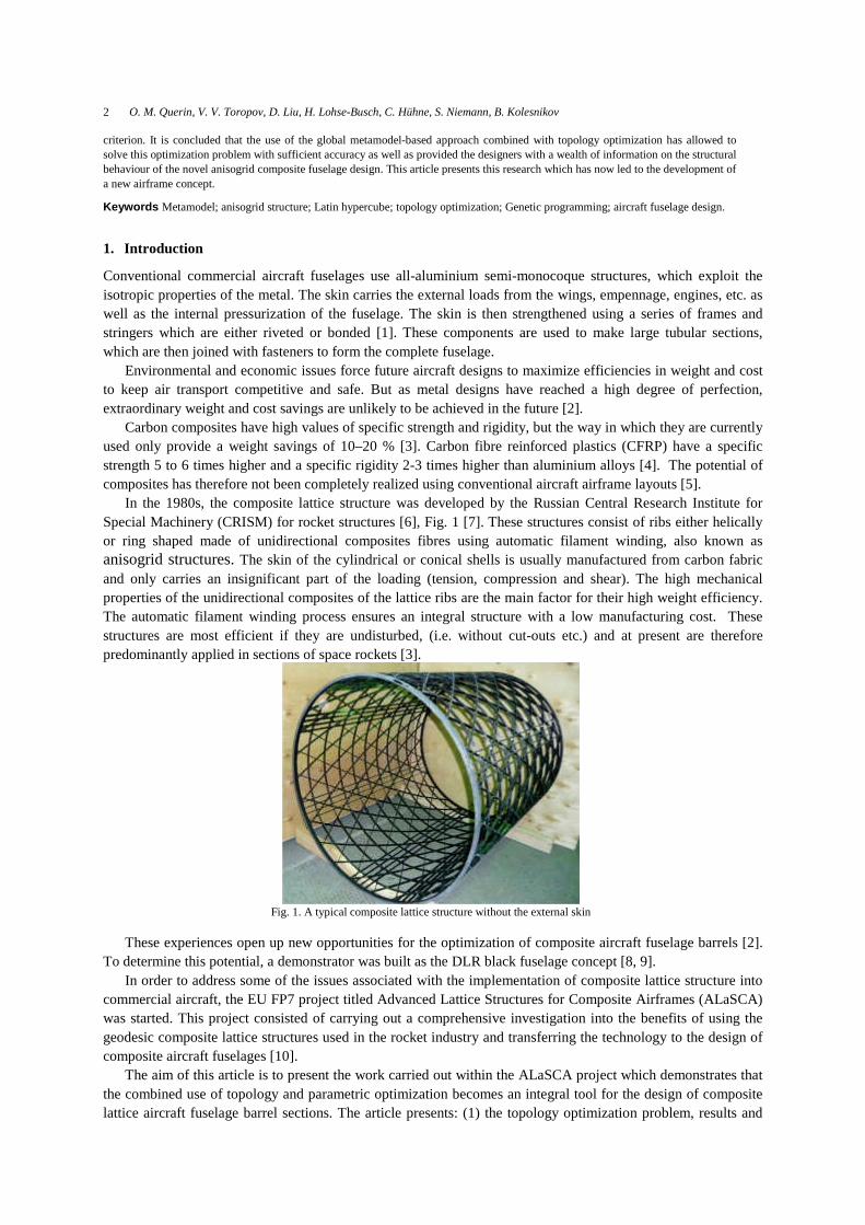
O. M. Querin, V. V. Toropov, D. Liu, H. Lohse-Busch, C. Hühne, S. Niemann, B. Kolesnikov12
bays. The helical ribs form an angle of 2φ between them, Fig. 16 below. This angle remains constant throughout
the barrel model.
Fig. 16. Skin bay geometry showing the triangular skin bays.
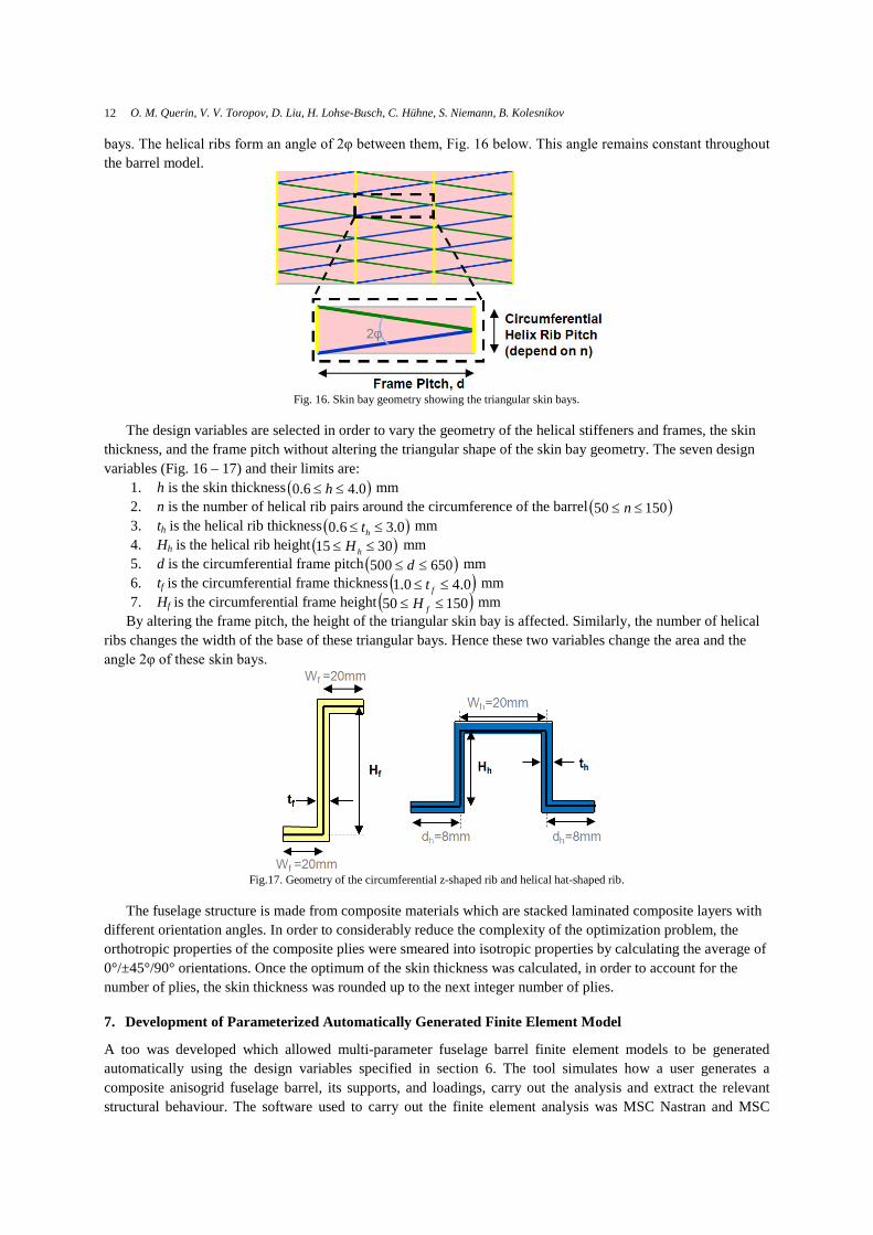
The design variables are selected in order to vary the geometry of the helical stiffeners and frames, the skin
thickness, and the frame pitch without altering the triangular shape of the skin bay geometry. The seven design
variables (Fig. 16 – 17) and their limits are:
1. h is the skin thickness 0.46.0 h mm
2. n is the number of helical rib pairs around the circumference of the barrel 15050 n3. th is the helical rib thickness 0.36.0 ht mm
4. Hh is the helical rib height 3015 hH mm
5. d is the circumferential frame pitch 650500 d mm
6. tf is the circumferential frame thickness 0.40.1 ft mm
7. Hf is the circumferential frame height 15050 fH mm
By altering the frame pitch, the height of the triangular skin bay is affected. Similarly, the number of helical
ribs changes the width of the base of these triangular bays. Hence these two variables change the area and the
angle 2φ of these skin bays.
Fig.17. Geometry of the circumferential z-shaped rib and helical hat-shaped rib.
The fuselage structure is made from composite materials which are stacked laminated composite layers with
different orientation angles. In order to considerably reduce the complexity of the optimization problem, the
orthotropic properties of the composite plies were smeared into isotropic properties by calculating the average of
0°/±45°/90° orientations. Once the optimum of the skin thickness was calculated, in order to account for the
number of plies, the skin thickness was rounded up to the next integer number of plies.
7. Development of Parameterized Automatically Generated Finite Element Model
A too was developed which allowed multi-parameter fuselage barrel finite element models to be generated
automatically using the design variables specified in section 6. The tool simulates how a user generates a
composite anisogrid fuselage barrel, its supports, and loadings, carry out the analysis and extract the relevant
structural behaviour. The software used to carry out the finite element analysis was MSC Nastran and MSC

Topology and Parametric Optimization of a Lattice Composite Fuselage Structure 13
Patran [21] with the automatic model generation tool written using the Patran Control Language (PCL) [22]. The
tool consisted of three separate parts: 1) a request file, 2) a pre-processing function and 3) a post processing
function.
1. The request session file contains the list of parameters which are used as the input parameters for the
model generation. This code contains the list of fuselage models to be simulated.
2. The pre-processing file generates the fuselage models, requests the analysis, and after the analysis is
complete, calls the post processing function.
3. The post processing file extracts and formats the results.
A user defined number of models can be generated and analysed in batch mode by specifying the design
variables from section 6 and the types of analysis to be carried out: linear elastic, buckling etc... The detailed
flowchart for the automated multi-parameter global barrel finite element tool is shown in Fig. 18.
Fig. 18.Automated multi-parameter global barrel finite element tool flowchart
The finite element model generated by this tool consists of the constant radius simplified fuselage barrel of
Fig. 15 with triangular skin bays bounded by hat-shaped helical ribs and z-shaped circumferential frames. The
skin is modelled with shell elements. The helical ribs, which are located on either side of the skin, are modelled
with offset beam elements. The circumferential frames, located on the inner side of the skin, are also modelled
with offset beam elements. A sample fuselage model is shown in Fig. 19 with a three dimensional visualization
of the stiffeners modelled with beam elements.
7.1. Applied loads
The load applied consisted of an upward gust at low altitude and cruise speed. At the free end, bending moments,
shear forces and torsion loads are applied as shown in Fig. 5. These loads were applied using rigid multipoint
constrains, which force a rigid barrel end. In this simplified fuselage barrel model, the passenger and cargo floors
were not directly modelled; but their masses were applied to the fuselage barrel where the floors contacted the
barrel, Fig. 6.

O. M. Querin, V. V. Toropov, D. Liu, H. Lohse-Busch, C. Hühne, S. Niemann, B. Kolesnikov14
Fig. 19.Sample fuselage barrel model with visualized frames and helical ribs
8. Generation of the Metamodel
As seen from the definition of the design variables in Section 6, the number of helical rib pairs around the
circumference of the barrel is an integer number that can vary between 50 and 150, and all other design variables
are continuous. This makes a direct application of a fast gradient-based optimization technique linked to the
finite element analysis impossible, and the use of one of the population-based techniques infeasible due to an
excessive number of calls for the finite element analysis to perform. Therefore, a metamodel-assisted
optimization approach has been chosen. The generation of the metamodel to represent the behaviour of the
fuselage barrel consisted of two stages:
1. Design of Experiments (DOE) to generate a cloud of response points and
2. Metamodel generation using Genetic Programming (GP).
8.1. Design of experiments
A 101 point DOE using the uniform Latin hypercube sampling method was used in this work [23]. Each -point
of the DOE corresponded to a different set of design variable values and a separate finite element model of the
barrel was generated and analysed to determine the performance of the fuselage barrel at each point.
8.2. Metamodel generation using GP
The Genetic Programming (GP) method [24] was used to generate the metamodels as it was found to be an
efficient way of producing high quality explicit global approximations [25, 26]. In order to prevent
discontinuities in the mathematical expressions and avoid creation of expressions of unnecessary complexity
(bloating) [27], the fitness function values F(i,t) given by Equation (3) for the ith individual in the tth generation
was defined as a weighted sum of different objectives:
),(),(10),(),(),( 4436
32211 tiFatiFatiFatiFatiF (3)
where F1 is the root mean square error (RMSE) of the ith individual in the tth generation evaluated on the given
data set, divided by the average RMSE of the population of individuals in the previous generation; F2 is the
square of the number of numerical coefficients (parameters) present in the individual; F3 is the number of
operations that are not defined (e.g. division by zero) in the individual evaluated at any of the DOE points; F4 is

Topology and Parametric Optimization of a Lattice Composite Fuselage Structure 15
the number of nodes that the individual is made of and a1, a2, a3 and a4 are weighting factors (that add up to 1)
determined by the exhaustive testing and tuning of the GP algorithm [25]. Their values were: a1=0.8989,
a2=0.001, a3=0.1 and a4=0.0001.
Using the GP methodology and the 101 finite element generated response sets, metamodels for four different
characteristics were built. These were the normalized responses of: 1) strength; 2) stiffness; 3) stability; and 4)
the fuselage barrel mass.
For the three structural responses of strains, stiffness and buckling, their margins of safety (MS) were
calculated. These margins of safety can have either positive or negative values. A positive margin of safety
shows that the computed value found in the structure does not violate the allowable value, and thus the structure
is acceptable. A negative margin of safety, on the other hand, shows that the computed value violates the
allowable value. Hence the structure fails and should be redesigned. The normalization of the studied results
allows for an easy comparison and, in the case of the margins of safety, a ready detection of failed fuselage
geometries.
8.2.1. Strength normalizing
The measure of strength used was the largest strains in the structure. This consisted of the tensile and
compressive strains in the frames and helical ribs, and the tensile, compressive and shears strains in the fuselage
skin.
The margin of safety of the strains was then calculated. This is normalization with respect to the maximum
allowable strain in the structure. It is a measure of whether the structures passes or fails due to the applied load.
The strain margin of safety and hence strength normalised response is computed using Equation (4).
01max
MS (4)
where is the computed strain and max the maximum allowable strain.
8.2.2. Stiffness normalizing
The margin of safety for stiffness is computed using Equation (5).
01min
S
SMSS (5)
where S is the computed stiffness and Smin the minimum allowable stiffness.
8.2.3. Stability normalizing
The margin of safety for buckling is computed using Equation (6).
01 BMS (5)
where is the computed linear buckling eigenvalue for the applied loads.
8.2.4. Mass normalizing
The mass per unit meter was computed for each model and then normalized against the largest mass per unit
length from the 101 DOE fuselage models.
9. Optimization of the Fuselage Barrel Using the Metamodels
Two different optimizations were carried out of the fuselage barrel of Fig. 15. In case I, only the strength
responses were used to generate the optimal fuselage geometry. This was done because the generation of the
strength results could be generated a lot faster than the buckling results. In case II, all of the responses describes
in section 8.2 were used to generate an optimal fuselage structure.
The optimum fuselage geometry predicted by the optimization of the metamodel was analysed by carrying
out a detailed finite element analysis of it, and the two responses were compared. The optimization result was
deemed acceptable if: 1) all margins of safety were positive; 2) the margins of safety predicted by the metamodel
optimization were within 0.10 of the equivalent MS obtained from the detailed finite element model; and 3) the
critical margin of safety from the predicted metamodel had a higher value than that of the detailed finite element

O. M. Querin, V. V. Toropov, D. Liu, H. Lohse-Busch, C. Hühne, S. Niemann, B. Kolesnikov16
analysis. When the result of the optimization on the metamodels obtained with the coarser FE mesh was checked
against the FE analysis from the finer mesh, the difference in the critical response value was treated as a constant
offset and added to the metamodel for correction, the optimization was repeated with the corrected metamodel
until the requirements were met.
9.1. Optimization of Case I
For case I where only strength constraints were used, two optimization loops were required. Table I gives the
responses predicted by the metamodel optimization (named Metamodel Prediction) together with the true
responses from the finite element analysis of the structure generated with the optimized design variables. Two
true responses were generated: 1) Using the parameterized automatically generated finite element tool from
section 7, named (DOE mesh) and 2) Using a finite element mesh generated from a converged study based on
the characteristics of design variables and the analysis results, named (Converged mesh).
Table I. Optima obtained using strength constraints
ModelTensile strain
(MS)Compressivestrain (MS)
Shear strain(MS)
Normalizedmass
Metamodel Prediction I 0.02 0.00 1.42 0.10
Optimum I (DOE mesh) 0.52 0.02 1.35 0.11
Optimum I (Converged mesh) 0.36 -0.09 1.21 0.11
Metamodel Prediction II 0.03 0.01 1.64 0.11
Optimum II (Converged Mesh) 0.54 0.04 1.54 0.12
The response predicted for the first optimum (Metamodel Prediction I) matches the DOE mesh response
(Optimum I (DOE mesh)) better than the converged mesh response (Optimum I (Converged mesh)).
The first optimum has a normalized weight of 0.10 with a predicted critical margin of safety of 0.00 for the
compressive strain, which for this problem is therefore the critical margin. In the finite element results for the
DOE mesh, the critical compressive strain margin of safety is 0.02, with all other critical margin positive and
hence giving conservative results. The optimization predicts accurately the critical structural response from a
DOE generated with the automatically generated finite element tool. Although this is expected as the DOE was
established with the same mesh. For the case of the converged mesh however, the critical margin has the
negative value of -0.09, which indicates that the fuselage structure fails in compression. The strains obtained
with the converged mesh have higher values than those obtained with the mesh generated with the parameterized
automatically generated finite element tool. Due to this failure in the compressive strain, a second optimization
loop was carried out. But due to the extra resolution of the converged mesh, instead of a requiring a zero margin
of safety from the optimized metamodel, a positive margin was now allowed.
The second optimum (Metamodel Prediction II) had a slightly positive (0.01) and hence conservative critical
margin of safety for the compressive strain. This time, the optimal design variables were only used to generate
the model Optimum II (Converged mesh) using the converged mesh. The value obtained for the critical
compressive strain was 0.04, which as it is less than 0.10 from the metamodel results it was deemed excellent.
The tensile strain was the only criteria where the refined FEM result was greater than 0.10, however as the
margin is positive and hence conservative, it was considered to not be important.
Table II shows the optimal values for the design variables for the two optimization runs. A weight efficient
optimum was reached by minimising the number of frames and ribs and thus generating large skin bays. These
are large triangular skin bays with a base width of 209.44 mm, a height of 627.70 mm and an angle between the
crossing helical ribs of 2φ=18.94°. The helical ribs have a tall and slender hat-shaped cross section with a
thickness of 0.66 mm, which is close to the minimal allowed valued of 0.60, and a height of 27.90 mm, also
close to the maximum allowed value of 30 mm. This had led to a large moment of inertia and thus to a high
bending stiffness. The circumferential frames, which are less instrumental in preventing fuselage bending have
become thin and small, with both of their dimensions reaching the minimal bounds of 1.0 mm and 50.0 mm
respectively. This case study has shown that when only strength responses are used in the optimization, the
fuselage barrel is generated with large skin bays; few thin tall helical ribs; and few thin small circumferential
frames.

Topology and Parametric Optimization of a Lattice Composite Fuselage Structure 17
Table II. Design variable values and strength constraints for successive optima
Design h (mm) n th (mm) Hh (mm) d (mm) tf (mm) Hf (mm)
Optimum II 2.28 60 0.66 27.90 627.70 1.00 50.00
9.2. Optimization of Case II
For case II, the three structural responses (strength, stability and stiffness) were used to generate the optimum.
The optimum results from the metamodel optimization together with the true response from the converged finite
element analysis are given in Table III.
Table III. Optimum obtained with strength, stiffness and stability constraints
ModelTensile strain
(MS)Compressivestrain (MS)
Strain Shear(MS)
Buckling(MS)
TorsionalStiffness (MS)
BendingStiffness (MS)
Normalizedmass
Metamodel Prediction III 0.20 0.23 1.27 0.00 1.21 0.89 0.29
Optimum III (Converged mesh) 0.62 0.08 1.09 -0.07 1.21 0.89 0.29
Unlike Case I, where the compressive strain was critical, when the full set of structural responses are
incorporated, buckling becomes the critical driving criteria in obtaining the optimu,. The metamodel predicted
optimum has a critical margin in buckling of 0.00 with a normalized weight of 0.29. However, when this was
checked with a finite element analysis using a converged mesh, this value was found to be -0.07. Although well
within our 0.10 range of acceptable solution, it was nevertheless negative, therefore meaning that the fuselage
would fail in buckling. Unfortunately due to time constraints, no additional optimization loops were able to be
carried out.
Table IV shows the optimal values for the design variables for this optimization run. Stability requirements
lead to smaller skin bays as larger panels buckle at a lower load than smaller panels. The skin bay area of the
third optimum decreased by 68% compared to the skin bays of the second optimum. The number of helix ribs
increase to 150, which is the upper bound for this variable. The frame pitch decreases to 501.50 mm, which is
close to the lower bound of 500. The resulting skin bays are small triangular skin bays with a base width of 83.78
mm, a height of 501.70 mm and a shallow angle between the crossing helical ribs of 2φ=9.55°. These small and
shallow skin bays are excellent against buckling. Also, the normalized weight increased considerably from 0.12
for the second optimum to 0.29 for the third optimum. The stability constraint was therefore found to be a weight
driving factor.
Table IV. Design variable values for optimum obtained with strength, stiffness and stability constraints
Design h (mm) n th (mm) Hh (mm) d (mm) tf (mm) Hf (mm)
Optimum III 1.71 150 0.61 27.80 501.70 1.00 50.00
The hat shaped helical ribs remain tall and thin with a thickness of 0.61 mm and a height of 27.80 mm. The
z-shaped circumferential frames remain unchanged for the third optimum with a thickness of 1.0 mm and a
height of 50.0 mm. These stiffeners are surprisingly thin and will suffer from local buckling, but as they were
modelled using beam elements, then only global buckling could be considered in the optimization. This is
soemthing which was learned from this work, and in future all stiffeners must be modelled using shell elements
in order to also capture local buckling effects. This of course would come at the expense of a much denser finite
element mesh and hence computational time to obtain a result.
9.2.1. Inclusion of ply thicknesses into optimal design
Since the optimal design (Optimum III) only used smeared ply properties, the skin thicknesses had to be
corrected to account for a standard CFRP ply thickness of 0.125 mm. This meant that the skin thickness
increased from 1.71 mm to 1.75 mm. The new structural responses are given in Table V.
Incorporating the ply thicknesses has slightly increased the buckling margin of safety, although it is still
negative with a value of -0.04. All other margins are positive. Considering the small negative buckling margin of

O. M. Querin, V. V. Toropov, D. Liu, H. Lohse-Busch, C. Hühne, S. Niemann, B. Kolesnikov18
safety, it is expected that a small change such as an increase in skin thickness could be sufficient to obtain a zero
or positive margin of safety. A preliminary light weight design, which fulfils the stability, strength and stiffness
requirements, can be produced from this optimization result.
Table V. Optimum III response using 0.125 mm laminate plies
ModelTensile strain
(MS)Compressivestrain (MS)
Strain Shear(MS)
Buckling(MS)
TorsionalStiffness (MS)
BendingStiffness (MS)
Normalizedmass
Optimum III (0.125mm ply) 1.15 0.19 1.31 -0.04 1.25 0.81 0.29
9.3. Comments on Results and Suggestions for Improvement
When only the strength constraints are used, the optimization results are valid and lead to a structurally sound
preliminary fuselage design. By adding stability and stiffness constraints to the strength constraints, although the
metamodel optimized result led to all MS being positive, the subsequent finite element analysis has led to a
negative critical margin in the buckling constraint. Although in the current study this could not be improved to
give all positive constraints, it is envisaged that the following two factors will address this issue: 1) an increase
in the number of data points in the DOE; 2) the use of converged finite element mesh to determine the response
of the structure at each of the DOE points. Because of time constraints this could not be implemented in this
study
10. Conclusions
Topology and parametric optimization was applied to the design of a fuselage barrel section. Topology
optimization led to a concentration of stiffeners being included on the upper and lower extremities of the
fuselage cross section and for these to form a criss-cross mesh pattern along the sides of the fuselage. This
design was then interpreted, modified to incorporate manufacturing constraints and simplified to allow it to be
parameterised in an automatic fashion.
The parameterised fuselage was then optimized further using Genetic Algorithms on a metamodel generated
with Genetic Programming from a 101 point Latin hypercube design of experiments. The optimal solution and
structural responses were verified with finite element simulations of the optimal lattice fuselage barrels. Two
optimum structures were obtained. The first structure was optimized only for strength requirement, producing a
light weigh fuselage with few thin helical ribs and circumferential frames, and large skin bays. The second
structure was optimized for strength, stability and stiffness requirements. The fuselage generated was
subsequently a heavier structure with smaller skin bays and more stiffeners. The stability criterion became the
driving factor for the skin bay size and the fuselage weight. This optimum fuselage structure requires only small
design change to produce an acceptable preliminary design. It is concluded that the use of the global metamodel-
based approach combined with topology optimization has allowed to solve this optimization problem with
sufficient accuracy as well as provided the designers with a wealth of information on the structural behaviour of
the novel anisogrid composite fuselage design.
Acknowledgments
The authors acknowledge the support of the European Commission and the Russian government within the
currently run FP7 Advanced Lattice Structures for Composite Airframes (ALaSCA) research project.
References
[1] Bruhn E.F., Analysis and Design of Flight Vehicle Structures, Jacobs Publishing Inc., 1973.
[2] Shanygin A., Fomin V., Kondakov I., Designing Pro-Composite Aircraft Concepts and Layouts to
Maximize Potential Benefits of High Specific Strength of CFRP, 28th Congress of the International
Council of the Aeronautical Sciences, 23 - 28 September 2012, Brisbane, Australia, Paper:ICAS 2012-
1.7.3.
[3] Vasiliev V.V., Razin A.F.,Anisogrid composite lattice structures for spacecraft and aircraft applications,
Composite Structures, October 2006, 76, (1–2), 182–189.

Topology and Parametric Optimization of a Lattice Composite Fuselage Structure 19
[4] Daniel I.M., Ishai O., Engineering Mechanics of Composite Materials, Oxford University Press, 2nd
ed., 2005.
[5] Ostrower J., “Flightglobal.com,” 15th March 2011. [Online]. Available:
http://www.flightglobal.com/news/articles/boeing-to-miss-787-performance-spec-albaugh-354340/.
[6] Vasiliev V.V., Barynin V.A., Rasin A.F., Anisogrid lattice structures – survey of development and
application, Composite Structures, November–December 2001,54, (2–3), 361-370.
[7] Vasiliev V.V., Barynin V.A., Razin A.F., Anisogrid composite lattice structures – Development and
aerospace applications, Composite Structures, February 2012, 94, (3), 1117–1127.
[8] Herbeck, L., Wilmes, H. R., Kolesnikov, B., and Kleineberg, M.,Technology and design development
for a CFRP fuselage. In 25th SAMPE Europe Conference, Paris, France, 2003.
[9] Wilmes, H., Kolesnikov, B., Fink, A., and Kindervater, C., New design concepts for a CFRP fuselage.
In Workshop at German Aerospace Centre (DLR) on Final Project of Black Fuselage, Braunschweig,
Germany, 2002.
[10] EU Research Project, Advanced Lattice Structures for Composite Airframes (ALasCA), Project
Reference: 265881, 2010 – 2013, Available: http://cordis.europa.eu/projects/rcn/97744_en.html
[Accessed 05/09/2013].
[11] Seitz A., Kruse M., Wunderlich T., Bold J., and Heinrich L., The DLR Project LamAiR: Design of a
NLF Forward Swept Wing for Short and Medium Range Transport Application, 29th AIAA Applied
Aerodynamics Conference, June 2011, AIAA 2011-3526
[12] Gerhold T., Overview of the hybrid RANS TAU-Code, Notes on Multidisciplinary Design, 2005, 89,
81-92.
[13] Bendsøe M. and Sigmund O., Topology Optimization: Theory, Methods and Applications, Springer,
2003.
[14] Altair OptiStruct19, [Online]. Available: http://www.altairhyperworks.com/Product,19,OptiStruct.aspx.
[Accessed 18/07/2013].
[15] Meyer R.W., Handbook of Pultrusion Technology, Chapman and Hall, 1985.
[16] Hexcel. [Online]. Available: http://www.hexcel.com/Resources/DataSheets/Prepreg-Data-
Sheets/8552_eu.pdf [Accessed 23/07/2013].
[17] Tan H.K.V., Bettess P., Bettess J.A., Elastic buckling of isotropic triangular flat plates by finite
elements, Applied Mathematical Modelling, October 1983, 7, (5), 311-316.
[18] Stefaniak D., Kolesnikov B., Kappel, E., Improving impact endangered CFRP structures by metal-
hybridisation, Proceedings of 12th European Conference on Spacecraft Structures, Materials and
Environmental Testing, European Space Agency, (Special Publication) ESA SP, v 691 SP, 2012.
[19] Wiedemann M., Sinapius M., Melcher J., Innovation Report, Institute of Composite Structures and
Adaptive Systems, DLR, 2012
[20] RohaSell-on-Line. [Online]. Available: http://www.rohasell-on-line.com/products.html [Accessed
23/07/2013].
[21] MSC Software. Simulating Reality, Delivering Certainty, [Online]. Available:
http://www.mscsoftware.com/ [Accessed 06/09/2013].
[22] PCL and Customization: MSC Software,
http://www.mscsoftware.com/training_videos/patran/Reverb_help/index.html#page/PCL%2520and%25
20Customization/customization_title.html [Accessed 06/09/2013].
[23] Toropov V.V., Bates S.J., O.M. Querin, Generation of Extended Uniform Latin Hypercube Designs of
Experiments, 9th International Conference on the Application of Artificial Intelligence to Civil,
Structural and Environmental Engineering, St. Julians, Malta, 18-21 September 2007, 90 – 101, ISBN:
978-1-61567-823-5.
[24] Koza J.R., Genetic Programming: On the Programming of Computers by Means of Natural Selection,
MIT press, Cambridge, USA, 1992
[25] Armani U., Khatir Z., Khan A., Toropov V.V., Polyinkin A., Thompson H., Kapur N., Noakes C.J.,
Control of Physical Consistency in Meta-model Building by Genetic Programming, Proceedings of the
Second International Conference on Soft Computing Technology in Civil, Structural and Environmental
Engineering, Civil-Comp Press, Stirlingshire, UK, Paper 43, 2011. doi:10.4203/ccp.97.43.

O. M. Querin, V. V. Toropov, D. Liu, H. Lohse-Busch, C. Hühne, S. Niemann, B. Kolesnikov20
[26] Toropov V.V., Polynkin A., Armani U., Alvarez L.F., Application of Metamodel Building by Genetic
Programming to Industrial Optimization Problems, IV European Congress on Computational
Mechanics (ECCM IV): Solids, Structures and Coupled Problems in Engineering, Paris, 16-21 May
2010, paper 1883
[27] Poli R., Langdon W. B., McPhee N. F., A Field Guide To Genetic Programming, Published via
http://lulu.com and freely available at http://www.gp-field-guide.org.uk, 2008. (with contributions by J.
R. Koza). [Accessed 06/09/2013].