Embed Size (px)
Citation preview
7. LS-DYNA Anwenderforum, Bamberg 2008
© 2008 Copyright by DYNAmore GmbH
Topology optimization based on graph theory of crash loaded flight passenger seats
Axel Schumacher, Christian Olschinka, Bastian Hoffmann
Hamburg University of Applied Sciences, Department of Automotive and Aeronautical Engineering, Berliner Tor 9, 20099 Hamburg, Germany, [email protected]
Summary: Today, real-world crashworthiness optimization applications are limited to sizing and shape optimization. Topology optimization in crashworthiness design has been withstanding until today any attempt of finding efficient solution algorithms. This is basically due to the high computational effort and the inherent sensitivity of crash simulation responses to design scatterings. In this work, the topology optimization problem shall be addressed with a new approach, in such a way as mathematical graphs are used to describe the optimization sequence (including geometry, loads, design variables and responses, etc.). This design conception is a good advance in topological model flexibility and allows for the application of new (e.g. rule-based) topology optimization algorithms. In this contribution, the topology optimization of crash loaded flight passenger seats is presented. Therefore, we focus on the necessary workflow which includes the graph-based description of the structure´s topology, the CAD description of the structure and the formulation of the crash problem in LS-DYNA. This workflow is included in an optimization loop. Keywords: Graph-based, structural optimization, topology optimization, crash simulation
Optimierung III
F - III - 11
7. LS-DYNA Anwenderforum, Bamberg 2008
© 2008 Copyright by DYNAmore GmbH
1 Introduction Mathematical optimization methods are commonly used to solve for optimum mechanical designs in industrial applications. Optimality of a structure then is defined e.g. in terms of static stiffness, a certain desired frequency response behaviour or crashworthiness performance. The problem of topology optimization as a very general approach to obtain optimum structures is often addressed as a material distribution problem. In crashworthiness design some drawback exists on the application of standard optimization methods, and particularly for topology optimization of crashworthiness designs the existing methods from static design optimization are not suitable. This leads to the approach of graph based topology optimization, which – after a brief overview on the terminology of crashworthiness and on the state of the art in structural optimization - is discussed in the following.
1.1 Crashworthiness Structures
1.1.1 Simulation of Crashworthiness Structures
Crashworthiness structures are mechanical structures subjected to dynamic loading, which have time-dependent system responses and are often of extensively nonlinear nature. Some typical applications are impact tests (e.g. automotive crash tests, aircraft drop testing, vehicle and aircraft interior testing). The dynamic behaviour of a structure can be simulated using explicit finite element code, i.e. solving the equations of motion for the nodal accelerations for a discrete set of finite element nodes in the time domain by using the equilibrium equation:
∑∑ −=⋅ ie FFxM &&r , (1)
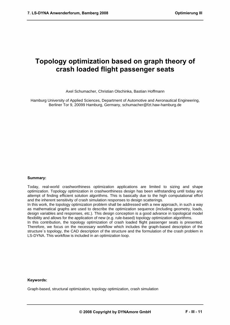
where M is the structure’s mass matrix and Fe and Fi are the vectors of external and internal forces, respectively. Using a central finite difference scheme, the solution allows for material, geometric and contact nonlinearities to be considered and therefore typical crash effects like fold buckling, cracking and plastification can be accounted for. Detailed crash simulations of aircraft seats are shown in [1].
Fig. 1: Time slice of an aircraft seat crash simulation
1.1.2 Optimization of Crashworthiness Structures
The optimization of crashworthiness structures usually involves the crash simulation by means of explicit finite element method as explained above. Typical design objectives that can be evaluated then are given in table 1.
Optimierung III
F - III - 12
7. LS-DYNA Anwenderforum, Bamberg 2008
© 2008 Copyright by DYNAmore GmbH
Tab. 1: Design objectives in crashworthiness optimization
Occupant dummy models, car petrol system
Biomechanical and other safety criteria
Car passenger compartmentComponent stiffness
Car frontal area, engine mount, A-pillar
Control of load paths
Smooth acceleration-time behaviour
Smooth force-displacement behavior
Force levelsCar frontal crash box, aircraft seat lower structure
Energy absorption
ExampleDesign objective
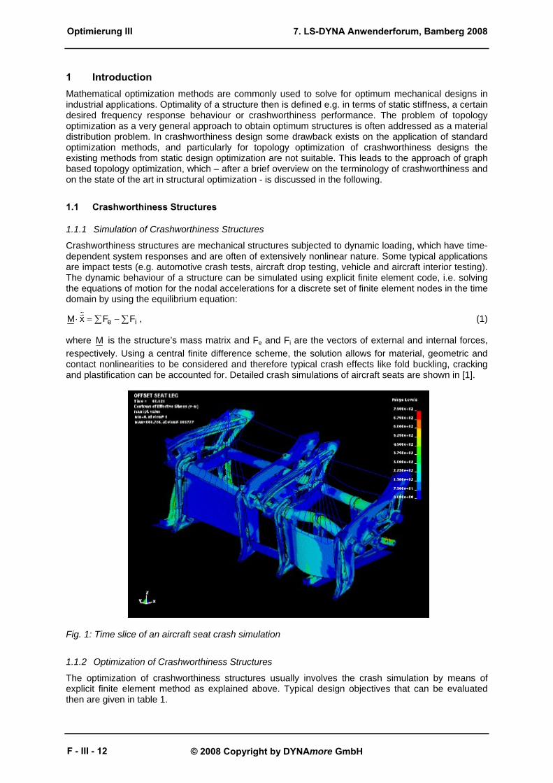
As an example application in crashworthiness design here the optimization of an aircraft seat structure shall be considered. The performance of an aircraft seat’s lower structure (so called “seat leg”) under dynamic certification testing conditions strongly depends upon its energy absorption capacity, its maximum plastic deformation in the frontal area (to secure survival space) as well as its cabin floor load introduction and its overall weight. Figure 2 illustrates the design task for an aircraft seat, which is to find an optimum design that minimizes the weight of the structure, such that straining, deformation and reaction force constraints are fulfilled.
Fig. 2: Mechanical problem (a) and design space with structural responses displacement ux(tE) and reaction force F(t) (b) The optimization problem then will be posed as:
( )ΩΩ
massmin (2)
subject to:
( ) ut
FtFmax < , ( ) uxEx utu < , ( ) u
Etmax ε<εΩ
.
30°
10°
14g downward 16g forward
30°
10°
14g downward 16g forward
10° yaw30° pitchDeceleration applied under
13,41 m/s10,67 m/sInitial velocity
16g14gMax. deceleration pulse amax
90 ms80 msHalf deceleration time tP
Forward testDownward test
10° yaw30° pitchDeceleration applied under
13,41 m/s10,67 m/sInitial velocity
16g14gMax. deceleration pulse amax
90 ms80 msHalf deceleration time tP
Forward testDownward test
amax
tP
amax
tP
???design Ω
( )tF
( )Ex tu
(a) (b)
Optimierung III
F - III - 13
7. LS-DYNA Anwenderforum, Bamberg 2008
© 2008 Copyright by DYNAmore GmbH
Here, Ω denotes the design space, ( )tF and ( )tux are the time-dependent load and displacement functions in the simulation time interval [ ]Et;0 as illustrated in figure 2, ( )tε is the plastic strain in the design space and a superscript u denotes an upper limit constraint of the respective values.
1.1.3 State of the Art in Crashworthiness Optimization
For the purposes of this paper, structural optimization problems can be roughly subdivided into optimization of statically and dynamically loaded structures. The second of which are crashworthiness structures. The simulation of statically loaded structures is computationally quite affordable, so even large scale optimization problems like the topology optimization in form of material distribution may be efficiently addressed (see [2]). The computation of crashworthiness problems is much more expensive, so today more or less only sizing and shape optimization problems can be handled satisfyingly (e.g. spot weld sizing and arrangement, sheet metal thickness optimization). For the topology optimization of crashworthiness structures rather few approaches exist, as for example the ground structure approach by C. Pedersen [3], which have some disadvantages in real world applications. In particular, this approach only handles truss-like structures while it is limited to a given number of possible topological designs (which is determined by the choice of the ground structure). A possible solution to these drawbacks shall be presented with the graph based optimization strategy in the following.
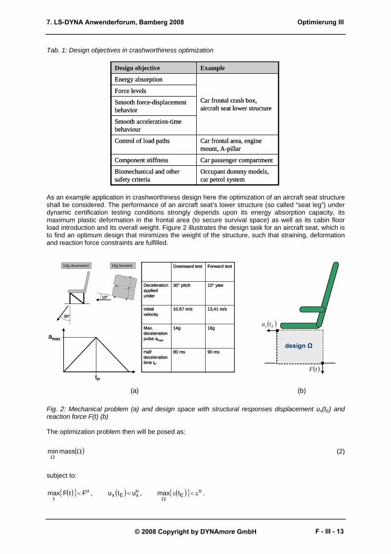
2 Graph Based Topology Optimization The idea of graph based topology optimization is to represent a design as a mathematical graph, which is made up of attributed sub-graphs representing themselves parts of the construction. These parts can for example be beams. The graph vertices’ attributes are used to store design parameters to be varied in the optimization, e.g. beam thicknesses. Topological changes to the design are then applied as topological changes to the graph, so topology optimization of a structure is understood as the topology optimization of its design graph. A shape optimization strategy can be included in an inner loop between two topological iterations. The number of possible designs is theoretically infinite, because topological changes shall be controlled by design rules, which can be successively applied to the current existing design. Figure 3 shows an example structure for a square frame made of four beams (each consisting of B1, BG, B2), that are linked together by linking vertices (L), and fixed in space using coordinate vertices (C).
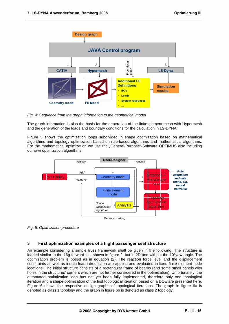
Fig. 3: A square beam frame example with its design graph representation Manipulating the underlying graph now may lead to a new topological design. The beam thicknesses are stored as attributes in the global beam vertex (BG). The geometrical representation of the structure in CATIA is generated by a JAVA control programm using the graph information (see Figure 4).
Optimierung III
F - III - 14
7. LS-DYNA Anwenderforum, Bamberg 2008
© 2008 Copyright by DYNAmore GmbH
Fig. 4: Sequence from the graph information to the geometrical model The graph information is also the basis for the generation of the finite element mesh with Hypermesh and the generation of the loads and boundary conditions for the calculation in LS-DYNA. Figure 5 shows the optimization loops subdivided in shape optimization based on mathematical algorithms and topology optimization based on rule-based algorithms and mathematical algorithms. For the mathematical optimization we use the „General-Purpose“-Software OPTIMUS also including our own optimization algorithms.
Fig. 5: Optimization procedure
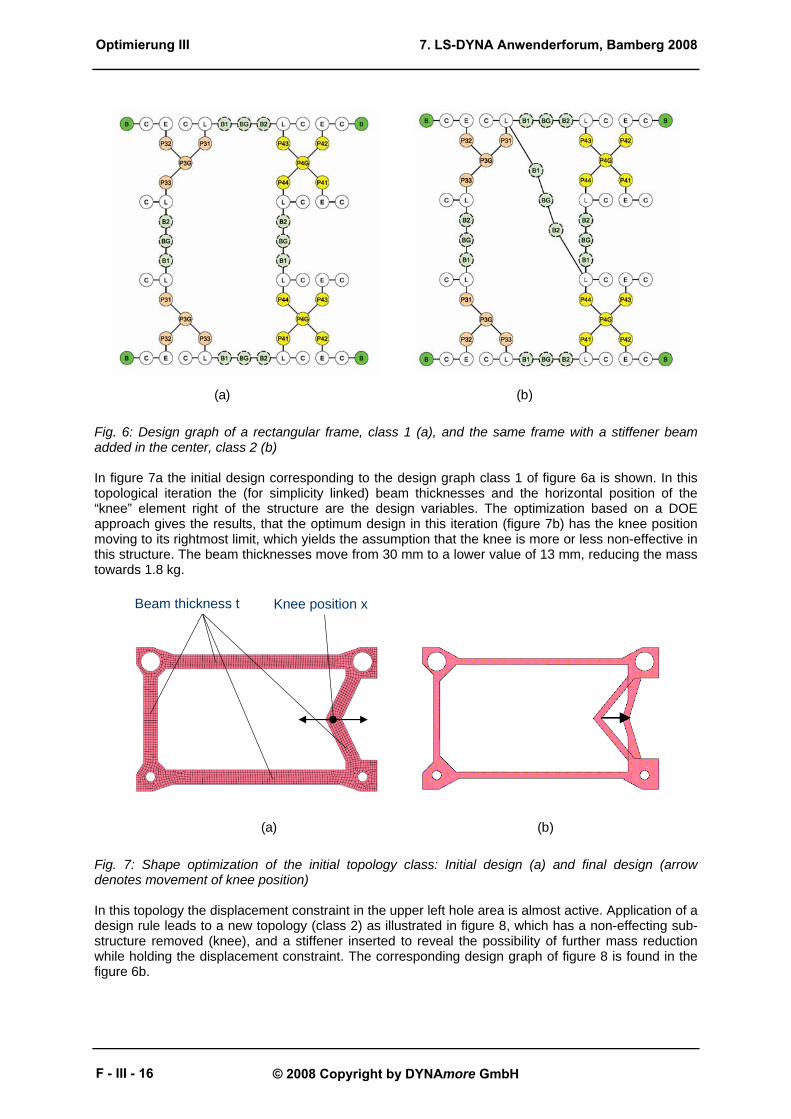
3 First optimization examples of a flight passenger seat structure An example considering a simple truss framework shall be given in the following. The structure is loaded similar to the 16g-forward test shown in figure 2, but in 2D and without the 10°yaw angle. The optimization problem is posed as in equation (2). The reaction force level and the displacement constraints as well as inertia load introduction are applied and evaluated in fixed finite element node locations. The initial structure consists of a rectangular frame of beams (and some small panels with holes in the structures’ corners which are not further considered in the optimization). Unfortunately, the automated optimization loop has not yet been fully implemented, therefore only one topological iteration and a shape optimization of the first topological iteration based on a DOE are presented here. Figure 6 shows the respective design graphs of topological iterations. The graph in figure 6a is denoted as class 1 topology and the graph in figure 6b is denoted as class 2 topology.
JAVA Control program
Design graph
CATIA
Additional FE Definitions
BC‘s
Loads
System responses
…Geometry model
Hypermesh
1. 2.
LS-Dyna
3.
FE Model
Simulation results
From
desi
gngr
aph
Geometry model
Finite element model
Part LibraryAdd
Remove
Shapeoptimization algorithm
Analysis
Database + Knowledge
base
Topology optimization
algorithm
User/Designer
Decision making
defines defines
Ruleadaptationand data
fitting, e.g. neural
networks
Optimierung III
F - III - 15
7. LS-DYNA Anwenderforum, Bamberg 2008
© 2008 Copyright by DYNAmore GmbH
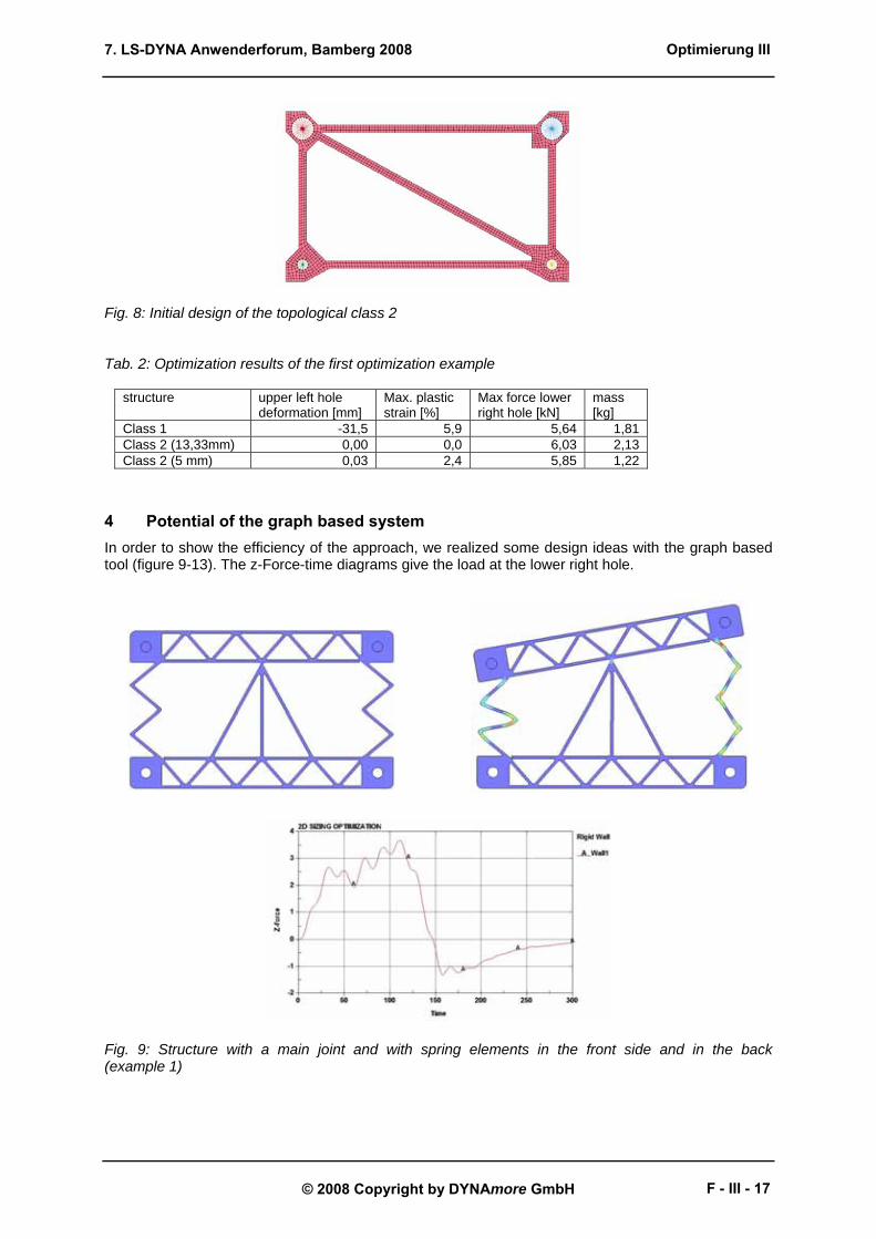
Fig. 6: Design graph of a rectangular frame, class 1 (a), and the same frame with a stiffener beam added in the center, class 2 (b) In figure 7a the initial design corresponding to the design graph class 1 of figure 6a is shown. In this topological iteration the (for simplicity linked) beam thicknesses and the horizontal position of the “knee” element right of the structure are the design variables. The optimization based on a DOE approach gives the results, that the optimum design in this iteration (figure 7b) has the knee position moving to its rightmost limit, which yields the assumption that the knee is more or less non-effective in this structure. The beam thicknesses move from 30 mm to a lower value of 13 mm, reducing the mass towards 1.8 kg.
Fig. 7: Shape optimization of the initial topology class: Initial design (a) and final design (arrow denotes movement of knee position) In this topology the displacement constraint in the upper left hole area is almost active. Application of a design rule leads to a new topology (class 2) as illustrated in figure 8, which has a non-effecting sub-structure removed (knee), and a stiffener inserted to reveal the possibility of further mass reduction while holding the displacement constraint. The corresponding design graph of figure 8 is found in the figure 6b.
(a) (b)
Beam thickness t Knee position x
(a) (b)
Optimierung III
F - III - 16
7. LS-DYNA Anwenderforum, Bamberg 2008
© 2008 Copyright by DYNAmore GmbH
Fig. 8: Initial design of the topological class 2 Tab. 2: Optimization results of the first optimization example
structure upper left hole deformation [mm]
Max. plastic strain [%]
Max force lower right hole [kN]
mass [kg]
Class 1 -31,5 5,9 5,64 1,81 Class 2 (13,33mm) 0,00 0,0 6,03 2,13 Class 2 (5 mm) 0,03 2,4 5,85 1,22
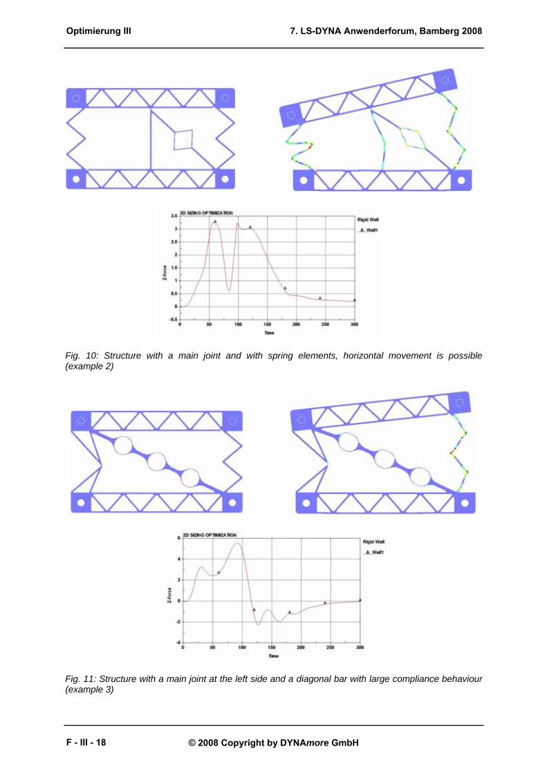
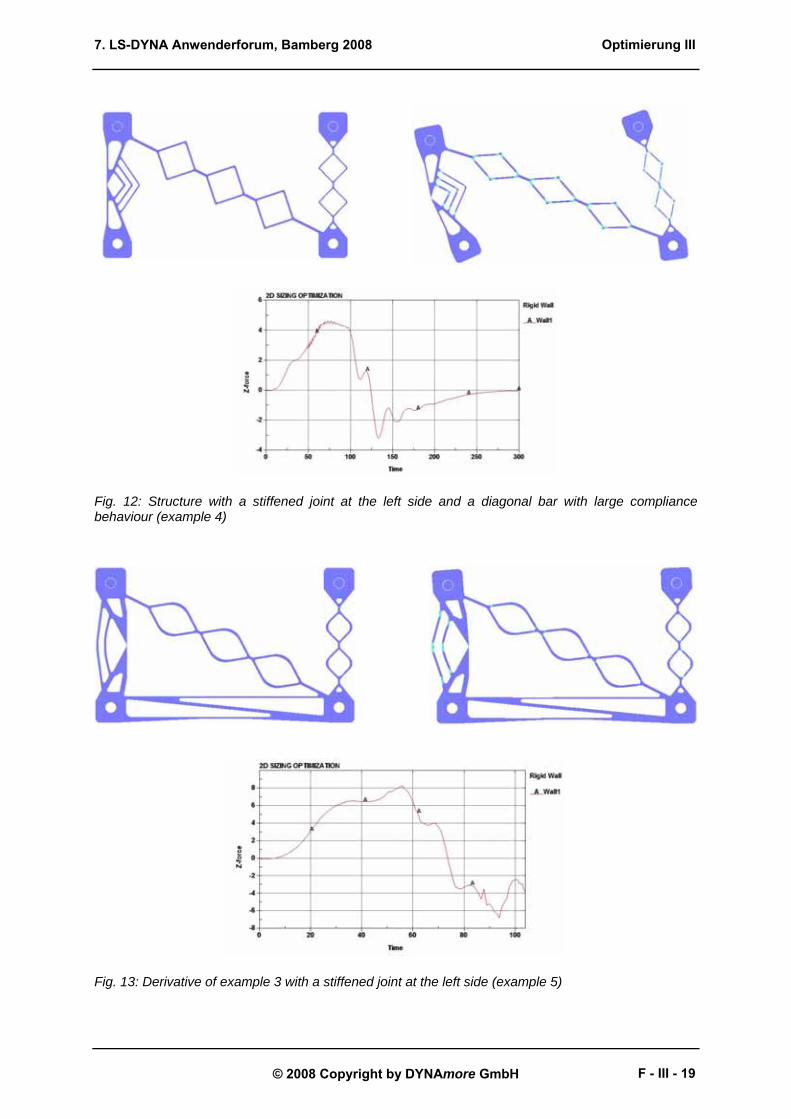
4 Potential of the graph based system In order to show the efficiency of the approach, we realized some design ideas with the graph based tool (figure 9-13). The z-Force-time diagrams give the load at the lower right hole.
Fig. 9: Structure with a main joint and with spring elements in the front side and in the back (example 1)
Optimierung III
F - III - 17
7. LS-DYNA Anwenderforum, Bamberg 2008
© 2008 Copyright by DYNAmore GmbH
Fig. 10: Structure with a main joint and with spring elements, horizontal movement is possible (example 2)
Fig. 11: Structure with a main joint at the left side and a diagonal bar with large compliance behaviour (example 3)
Optimierung III
F - III - 18
7. LS-DYNA Anwenderforum, Bamberg 2008
© 2008 Copyright by DYNAmore GmbH
Fig. 12: Structure with a stiffened joint at the left side and a diagonal bar with large compliance behaviour (example 4)
Fig. 13: Derivative of example 3 with a stiffened joint at the left side (example 5)
Optimierung III
F - III - 19
7. LS-DYNA Anwenderforum, Bamberg 2008
© 2008 Copyright by DYNAmore GmbH
Tab. 3: Summary of the performance of the structures shown in figure 9-13
example upper left hole deformation [mm]
Max. plastic strain [%]
Max force lower right hole [kN]
mass [kg]
1 -2,6 6,8 3,19 0,856 2 -35,0 7,3 4,95 0,844 3 -12,5 12,5 5,58 0,911 4 -72,0 15,1 4,66 0,580 5 -7,0 10,7 8,34 0,818
5 Rules for changing the topology of the structure In this chapter we describe some examples of expert knowledge which we can use for the development of crash structure components. E.g. a scan procedure identifies areas, where the buckling index is large and therefore are indicated to be substituted, if buckling is not desired:
∫∑ ∑ ∆⋅ξ⋅δ−⋅=η= =
T
0ij
N
1i
N
1jr
d
ij dtv)1(N1 2
2ij
r (3)
with η - buckling index N - number of finite element nodes i,j - indices of the finite element nodes ξ - distance filter dij - distance of the nodes r - filter radius δij - Kronecker symbol (yields 1 for i=j, otherwise 0)
ijvr
∆ - relative node movement
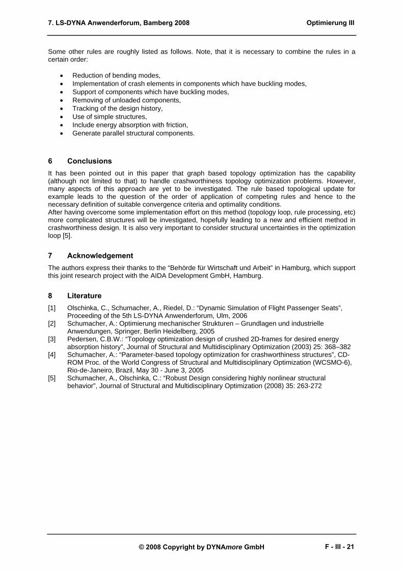
Anorder approach is the use of the bubble method [2] for positioning of added bars and beams. Core of the bubble method is the positioning of holes by using analytical characteristic functions or with a numerical approach [4]. Figure 8 shows the process.
Fig. 8: Positioning of components using hole positioning criteria
hole positioning on a analysis shell
?
bubble 1
bubble 2
knowledge-based algorithm for the arrangement
of a new beam
include the beam in the structure and carry out
a shape optimization
design task: optimize the frame structure
modeling of an analysis shell
Optimierung III
F - III - 20
7. LS-DYNA Anwenderforum, Bamberg 2008
© 2008 Copyright by DYNAmore GmbH
Some other rules are roughly listed as follows. Note, that it is necessary to combine the rules in a certain order:
• Reduction of bending modes, • Implementation of crash elements in components which have buckling modes, • Support of components which have buckling modes, • Removing of unloaded components, • Tracking of the design history, • Use of simple structures, • Include energy absorption with friction, • Generate parallel structural components.
6 Conclusions It has been pointed out in this paper that graph based topology optimization has the capability (although not limited to that) to handle crashworthiness topology optimization problems. However, many aspects of this approach are yet to be investigated. The rule based topological update for example leads to the question of the order of application of competing rules and hence to the necessary definition of suitable convergence criteria and optimality conditions. After having overcome some implementation effort on this method (topology loop, rule processing, etc) more complicated structures will be investigated, hopefully leading to a new and efficient method in crashworthiness design. It is also very important to consider structural uncertainties in the optimization loop [5].
7 Acknowledgement The authors express their thanks to the “Behörde für Wirtschaft und Arbeit” in Hamburg, which support this joint research project with the AIDA Development GmbH, Hamburg.
8 Literature [1] Olschinka, C., Schumacher, A., Riedel, D.: “Dynamic Simulation of Flight Passenger Seats”,
Proceeding of the 5th LS-DYNA Anwenderforum, Ulm, 2006 [2] Schumacher, A.: Optimierung mechanischer Strukturen – Grundlagen und industrielle
Anwendungen, Springer, Berlin Heidelberg, 2005 [3] Pedersen, C.B.W.: “Topology optimization design of crushed 2D-frames for desired energy
absorption history”, Journal of Structural and Multidisciplinary Optimization (2003) 25: 368–382 [4] Schumacher, A.: “Parameter-based topology optimization for crashworthiness structures”, CD-
ROM Proc. of the World Congress of Structural and Multidisciplinary Optimization (WCSMO-6), Rio-de-Janeiro, Brazil, May 30 - June 3, 2005
[5] Schumacher, A., Olschinka, C.: “Robust Design considering highly nonlinear structural behavior”, Journal of Structural and Multidisciplinary Optimization (2008) 35: 263-272
Optimierung III
F - III - 21

7. LS-DYNA Anwenderforum, Bamberg 2008
© 2008 Copyright by DYNAmore GmbH
Optimierung III
F - III - 22