Embed Size (px)
Citation preview

Cooling with Viessmann heat pumps
● ”Natural cooling” – Lower CO2 emissions than with conventional cooling systems
● Utilisation of all available low ground and groundwater temperatures in summer
● Optimum use in conjunction with heatdistribution systems
● Improved regeneration of ground probes andadditional storage of energy during summer months
● Cooling COP between 15 and 20, therefore 3 to 4 timesgreater than conventional air-conditioning systems
TopTechnology

2
Reversible operation
Introduction
Conventionally, in Germany, mostheat pump systems are used to heata building and to provide domestichot water (DHW). Where appropriate,a second device is then installed tocool the building. The option of achie-ving both functions – heating andcooling – alternately with only onepiece of equipment, is still relatively unknown in Germany. However, in the USA, heat pumpswhich are able to operate as heatingand cooling equipment have beenfirmly established in the market, and consequently enjoy widespreadappeal.
A conventional refrigerator and acompressor-driven heat pump workaccording to the same principle –they differ only in the direction oftheir heat flow. The most importantcomponents (evaporator, condenser,compressor, and expansion valve)are, therefore, identical for both types of equipment. Their principledifference lies in the optimisation oftheir respective tasks, which in onecase aims to increase and in theother to decrease temperatures.
To enable a compressor-driven heat pump to be used for cooling purposes, it would be sufficient to reverse the flow direction of the compressor and the expansion valve, thereby reversing the flow of the refrigerant and consequentlythe generated heat.
Heat transfer(to the heating system)
Heat supply(environment)
Compressor
Expansionvalves
Evaporator
Condenser
Fig. 1: Simplified function diagram for a heat pump with reversible operation in heating mode
Heat pump with reversible
operation in heating mode
The installation of a four-way valveand a second expansion valve intothe refrigeration circuit also haveachieved good technical results. This four-way valve enables the flow direction to be changed automatically for the entire system.Through the installation of the four-way valve, the compressor can –whether heating or cooling – alwaysretain its original flow direction.
In heating mode, the compressorpushes the gaseous refrigerant towards the heat exchanger of the heating system. There, the refrigerant condenses and transfersits energy (heat) to the heating system (heating DHW or air) (Fig. 1).
Reversible operation
3
Heat supply(from heating system or from accommodation)
Heat transfer (to the environment)
Compressor
Expansionvalves
Condenser
Evaporator
Fig. 4: Vitotres 343 – Compact unit for energy-efficient houses: heat pump combined with mechanical domestic ventilation and DHW cylinder
Fig. 3: Menu-guided control unit CD 70
Heat pumps with reversible
operation in cooling mode
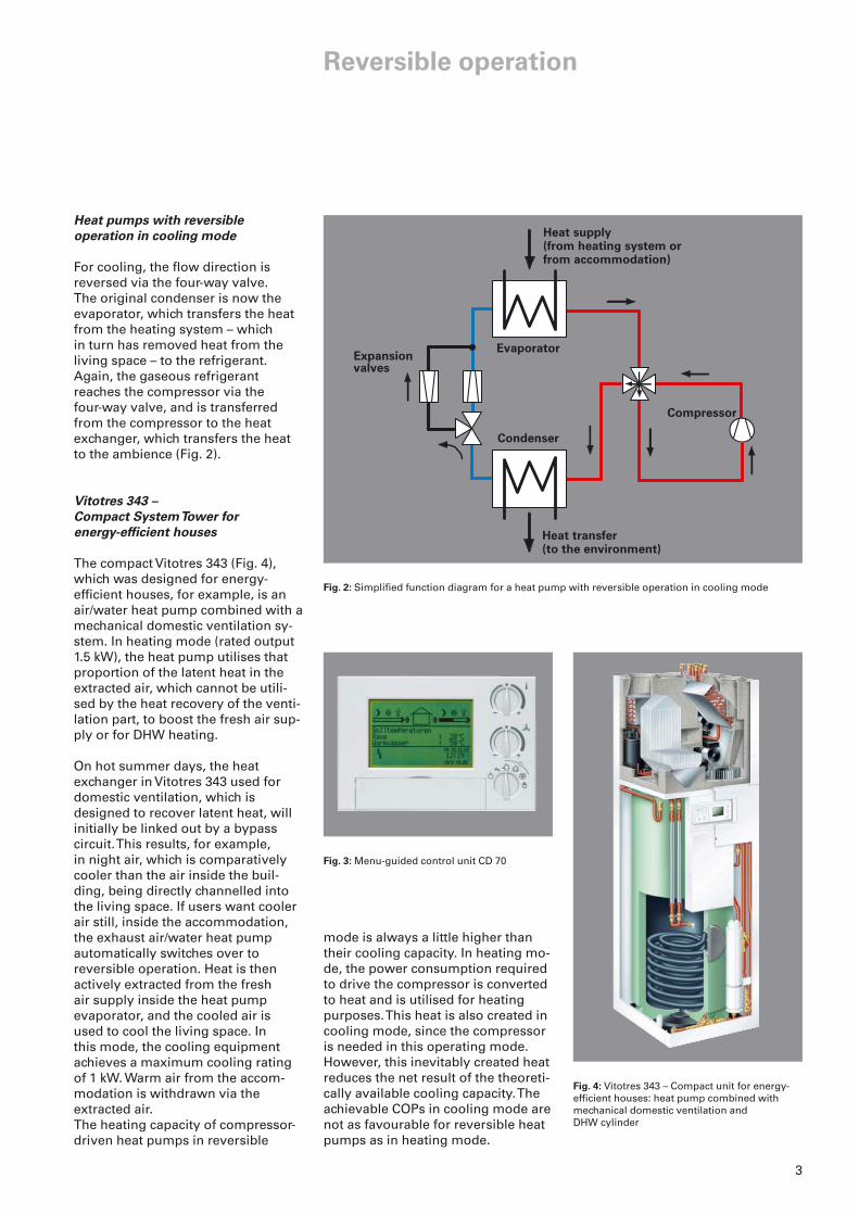
For cooling, the flow direction is reversed via the four-way valve. The original condenser is now theevaporator, which transfers the heatfrom the heating system – which in turn has removed heat from the living space – to the refrigerant.Again, the gaseous refrigerant reaches the compressor via the four-way valve, and is transferredfrom the compressor to the heatexchanger, which transfers the heatto the ambience (Fig. 2).
Vitotres 343 –
Compact System Tower for
energy-efficient houses
The compact Vitotres 343 (Fig. 4),which was designed for energy-efficient houses, for example, is anair/water heat pump combined with amechanical domestic ventilation sy-stem. In heating mode (rated output1.5 kW), the heat pump utilises thatproportion of the latent heat in theextracted air, which cannot be utili-sed by the heat recovery of the venti-lation part, to boost the fresh air sup-ply or for DHW heating.
On hot summer days, the heatexchanger in Vitotres 343 used fordomestic ventilation, which is designed to recover latent heat, willinitially be linked out by a bypass circuit. This results, for example, in night air, which is comparatively cooler than the air inside the buil-ding, being directly channelled intothe living space. If users want coolerair still, inside the accommodation,the exhaust air/water heat pump automatically switches over to reversible operation. Heat is then actively extracted from the fresh air supply inside the heat pump evaporator, and the cooled air isused to cool the living space. In this mode, the cooling equipmentachieves a maximum cooling ratingof 1 kW. Warm air from the accom-modation is withdrawn via the extracted air.The heating capacity of compressor-driven heat pumps in reversible
mode is always a little higher than their cooling capacity. In heating mo-de, the power consumption requiredto drive the compressor is convertedto heat and is utilised for heatingpurposes. This heat is also created incooling mode, since the compressoris needed in this operating mode.However, this inevitably created heatreduces the net result of the theoreti-cally available cooling capacity. Theachievable COPs in cooling mode arenot as favourable for reversible heatpumps as in heating mode.
Fig. 2: Simplified function diagram for a heat pump with reversible operation in cooling mode

4
”Natural Cooling”
A
B
C
D
F
G
H
K
E
Fig. 5: Simplified system diagram for coolingwith an underfloor heating system
Fig. 6: Vitocal 300 brine/water and water/waterheat pump
E.g. ground probe
Primary pump
Three-way diverter valve heating/cooling (primary circ)
Heat exchanger – cooling
Circulation pump – cooling
Underfloor heating system
Three-way diverter valve heating/cooling (secondary circuit)
Secondary pump
Vitocal 300 or Vitocal 350heat pump
A
B
C
D
E
F
G
H
K
Fig. 7: Heating circuit control unit CD 60 withsoft start and integral cooling and solar function – up to three loading groups can be regulated
Generally during the summer, tem-peratures inside buildings are higherthan underground or in groundwater.Under these conditions, the lowertemperatures of the ground/ground-water, which in winter serves asenergy source, can be utilised to directly cool the inside of buildings.
For this purpose, some heat pumpcontrol units feature a so-called ”Natural cooling” function. This function is not possible for air/waterheat pumps, due to high outsidetemperatures in summer.
The ”Natural cooling” function canbe realised with only a few additionalcomponents (heat exchanger, three-way valve and circulation pump).This results in a pleasant additionaluse for Vitocal heat pumps.
Generally, the capability of this cool-ing function cannot be comparedwith air-conditioning equipment orwater chillers. The cooling capacitydepends on the heat source tempera-ture, the size of the heat source andthe period of loading, which may besubject to seasonal fluctuations. For example, experience shows that the ground stores more energyat the end of summer, consequentlyreducing the cooling capacity.
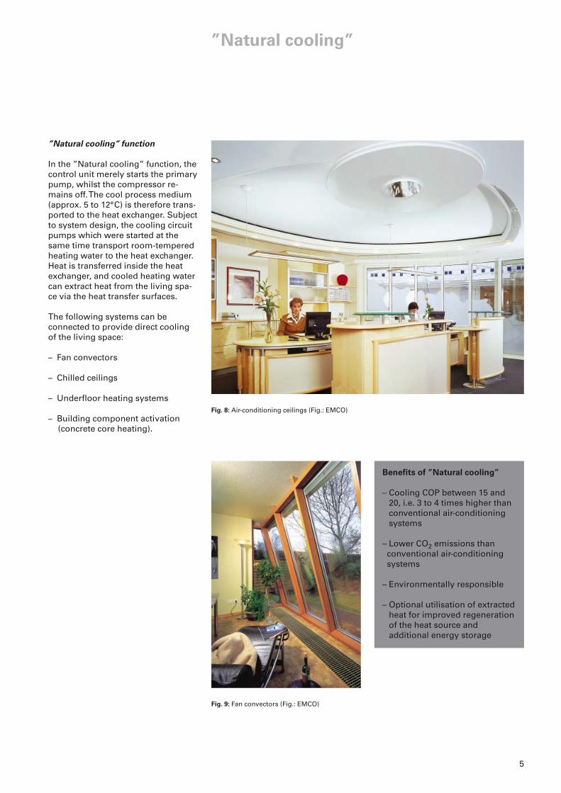
Fig. 9: Fan convectors (Fig.: EMCO)
Fig. 8: Air-conditioning ceilings (Fig.: EMCO)
”Natural cooling”
”Natural cooling” function
In the ”Natural cooling” function, thecontrol unit merely starts the primarypump, whilst the compressor re-mains off. The cool process medium(approx. 5 to 12°C) is therefore trans-ported to the heat exchanger. Subjectto system design, the cooling circuitpumps which were started at the same time transport room-temperedheating water to the heat exchanger.Heat is transferred inside the heatexchanger, and cooled heating watercan extract heat from the living spa-ce via the heat transfer surfaces.
The following systems can beconnected to provide direct coolingof the living space:
– Fan convectors
– Chilled ceilings
– Underfloor heating systems
– Building component activation(concrete core heating).
Benefits of ”Natural cooling”
– Cooling COP between 15 and20, i.e. 3 to 4 times higher thanconventional air-conditioningsystems
– Lower CO2 emissions thanconventional air-conditioningsystems
– Environmentally responsible
– Optional utilisation of extractedheat for improved regenerationof the heat source and additional energy storage
5
6
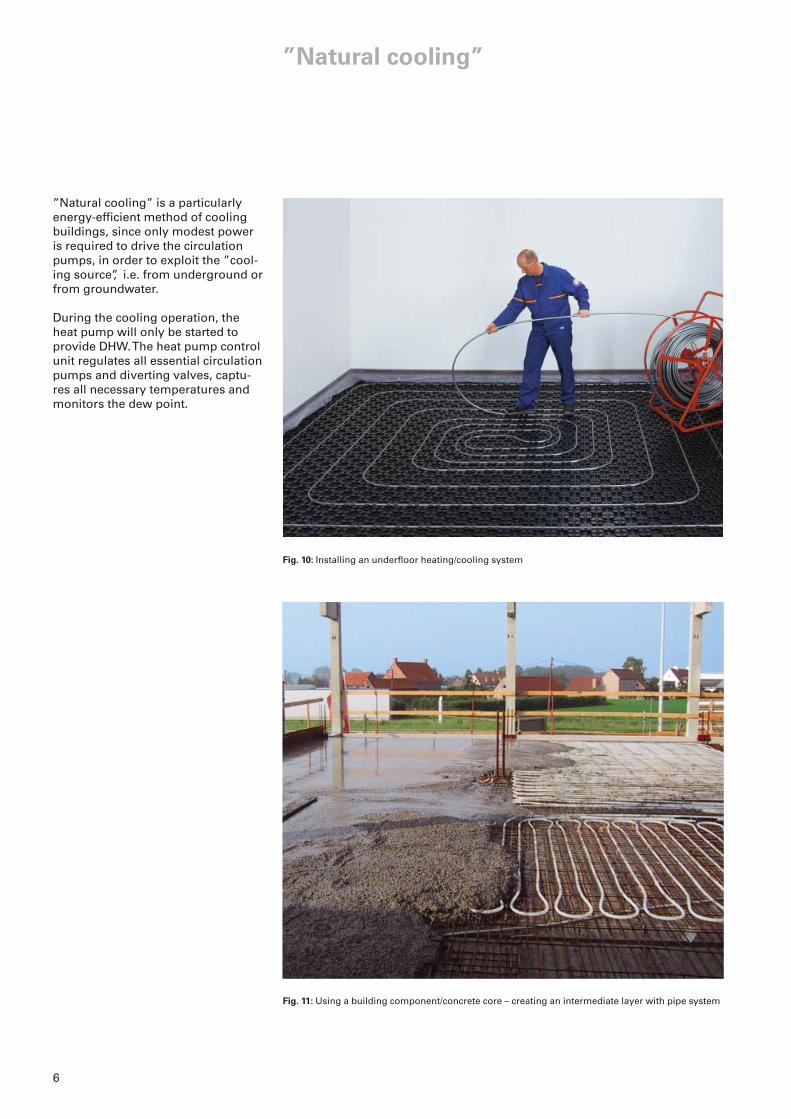
Fig. 10: Installing an underfloor heating/cooling system
Fig. 11: Using a building component/concrete core – creating an intermediate layer with pipe system
”Natural cooling”
”Natural cooling” is a particularlyenergy-efficient method of coolingbuildings, since only modest poweris required to drive the circulationpumps, in order to exploit the ”cool-ing source”, i.e. from underground orfrom groundwater.
During the cooling operation, theheat pump will only be started toprovide DHW. The heat pump controlunit regulates all essential circulationpumps and diverting valves, captu-res all necessary temperatures andmonitors the dew point.

7
”Natural cooling”
Cooling the living space
With conventional air-conditioningsystems, cooled air is supplied intothe living space via one or more ducts, which also remove heated air.Compact units for energy-efficienthouses operate according to the same principle. Both are air-handlingunits, which provide essential heattransfer through air movement.
Reversible heat pumps and thosewith ”Natural cooling” function, on the other hand, are generallyconnected to a hot water heating system. On cold days, that systemtransfers heat from the heating waterto the rooms to be heated using heattransfer surfaces.
Radiators are particularly unsuitablefor a heat transfer in the opposite direction – i.e. for cooling a room.The comparatively small temperatu-re differential between the heatingwater and the room temperature in summer, and the relatively smallsurface area of radiators mean thatonly a modest heat transfer occursthrough convection and radiation.The arrangement of the heat transfersurfaces near floor level is also of little benefit for cooling operations.In addition, radiators are particularlyprone to dew corrosion due to theirlocation and design.
Underfloor heating systems are better suited to this purpose becauseof their larger area. However, cooledair collects at floor level and cannotrise. For this reason, heat from underfloor heating systems is transferred almost exclusively by radiation. On the other hand, the entire floor area is available as a cooling surface, enabling the roomtemperature to be influenced in accordance with personal require-ments.
Improved permeation of the livingspace with cooled air is achieved by the additional installation of a domestic ventilation system withheat recovery (e.g. Vitovent 300, Fig. 12).
Heat can be dissipated even more effectively via chilled ceilings. Hot air collects under the ceiling and iscooled by its surface. This makes itsink to the floor, enabling hot air toreplace it. The resulting circulationleads greater volumes of air past the cooling surface, compared to underfloor cooling. However, chilledceilings will not generally replaceheating systems. For that reason,they are installed in most cases alongside radiators or underfloorheating systems into which they are integrated via an additional heatexchanger, which provides hydraulicsystem separation.
Fan convectors are especially effective, since these operate with afan which also creates a controllablevolume flow. This allows larger airvolumes to be channelled past theheat exchanger surfaces, resulting inthe ability to effectively cool a spacein a short time. The additional optionof being able to vary the volume flowvia the fan allows for sensitive spacecooling. Also, fan convectors are notprone to dew corrosion, providedany condensate is drained off.
Independent of the method of coo-ling – reversible operation or ”Natu-ral cooling” – the dew point must bemonitored by the heat pump controlunit in all cases. For example, thesurface temperature of an underfloorheating system in cooling modemust not fall below 20°C. The dewpoint monitor keeps the flow tempe-rature inside the heating system highenough for cooling to prevent the actual temperature falling below thedew point. This prevents the risk ofair-borne humidity precipitating onthe floor.
Practical tips
For the installation of the ”Natu-ral cooling” function in directconnection with heat pumps, werecommend the use of a coolingheat exchanger and a mixer. Reason: Filling the cooling distribution system with anti-freeze reduces the capacity ofthe heat pump in heating mode,thereby reducing the COP.
A mixer further guarantees thefunction of a curve, avoiding cycling by the dew point switch.The cooling capacity of the over-all system increases, as it workswithout interruption.
Pipework, fittings and the cool-ing heat exchanger must be thermally insulated with vapour-proof material.
Fig. 12: Vitovent 300 domestic ventilation system with heat recovery

8
If, fan convectors (on-site provision,e.g. as supplied by EMCO or GEA)are used for cooling operation insummer, alongside the existing heating system, such convectors arehydraulically integrated directly viathe brine circuit. The fan convectormust therefore be resistant to anti-freeze. A mixer for the cooling circuitis not essential. However, a separateroom controller for the fan convectorhas proven to be advantageous.
A frost stat (on-site provision) mustbe installed where brine circuit temperatures below freezing cannotbe prevented, to block the coolingoperation when necessary.
The fan convectors should be sizedsubject to the flow/return tempera-ture combination 12/16°C (approx.).
As ambient air is circulated by fanconvectors, rooms will cool downagain relatively rapidly (capacity subject to heat source). The entireroom is flushed. Since the air trans-port is created by a fan, its noise development, too, must be taken intoaccount. Parallel operation (heatingand cooling) is feasible with this version. Cooling would then be provided by the fan convector, andheating via the heat pump.
Additional installation costs are incurred in conjunction with conven-tional heat distribution systems (heating circuit or underfloor heatingsystem).
Suitable heat pumps:
Vitocal 300, 350 and 343(not air/water heat pumps).
Cooling with fan convectors
Practical tips
The fan convector must beequipped with a drain to removeany condensate created duringthe cooling operation.
Cooling systems with air circula-tion operate very quickly, makingthem also suitable for short-termcooling demands.
Fig. 13: Cooling with fan convectors
9
Cooling with chilled ceilings
VL = Flow
RL = Return
Practical tips
The chilled ceiling should be sized in accordance with theflow/return temperature pair14/18°C (approx.). A room tempe-rature sensor is required in the living space to achieve optimumcooling.
Chilled ceilings operate quietlyand effectively, as they absorband convert heat at ceiling levelwhere natural convection takes it. Chilled ceilings incur additionalinstallation costs.
Position humidity sensors so thatthey can be surrounded by theambient air in the referenceroom.
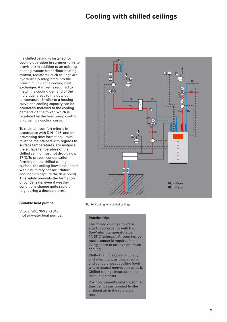
If a chilled ceiling is installed for cooling operation in summer (on-siteprovision) in addition to an existingheating system (underfloor heatingsystem, radiators), such ceilings arehydraulically integrated into the brine circuit via the cooling heatexchanger. A mixer is required tomatch the cooling demand of the individual areas to the outside temperature. Similar to a heatingcurve, the cooling capacity can be accurately matched to the coolingdemand via the mixer, which is regulated by the heat pump controlunit, using a cooling curve.
To maintain comfort criteria in accordance with DIN 1946, and forpreventing dew formation, limitsmust be maintained with regards tosurface temperatures. For instance,the surface temperature of the chilled ceiling must not drop below17°C. To prevent condensation forming on the chilled ceiling surface, the ceiling flow is equippedwith a humidity sensor ”Natural cooling” (to capture the dew point).This safely prevents the formation of condensate, even if weather conditions change quite rapidly (e.g. during a thunderstorm).
Suitable heat pumps:
Vitocal 300, 350 and 343(not air/water heat pumps).
Fig. 14: Cooling with chilled ceilings

10
Cooling with underfloor heating
systems
VL = Flow
RL = Return
Floor covering Tiles Carpet
Distance between mm 75 150 300 75 150 300pipes
Cooling capacity with
pipe diameter:
– 10 mm W/m2 45 35 23 31 26 19– 17 mm W/m2 46 37 25 32 27 20– 25 mm W/m2 48 40 28 33 29 22
Table 1: Estimated cooling capacity of an underfloor heating system, subject to the distance betweenpipes (pipework) and floor covering(assumed flow temperature: approx. 14°C, return temperature: approx. 18°C) Source: Velta
Practical tips
The underfloor heating systemsshould be sized in accordance with the flow/return temperaturepair 14/18°C (approx.). The following table can assist inestimating the possible cooling capacity of an underfloor heatingsystem.
Subject to the construction of the underfloor heating system, a room temperature reduction of between 2 and 4 K can be achieved.
The cooling capacity is subject to the effective area, the type of covering and the method of laying.
Fig. 15: Cooling with underfloor heating systems
Underfloor heating systems can beused to heat buildings and living spaces as well as to cool them down.
Underfloor heating systems are integrated into the brine circuit via a cooling heat exchanger. A mixer is required to match the cooling demand of the accommodation tothe outside temperature. Similar to a heating curve, the cooling capacitycan be accurately matched to thecooling demand via the mixer, which is regulated by the heat pumpcontrol unit, using a cooling curve.
To maintain comfort criteria in accordance with DIN 1946, and forpreventing dew formation, limitsmust be maintained with regards tosurface temperatures. For instance,the surface temperature of the underfloor heating system must notdrop below 20°C. To prevent conden-sation forming on the underfloorheating system surface, the under-floor system flow is equipped with a humidity sensor ”Natural cooling”(to capture the dew point). This safely prevents the formation of condensate, even if weather condi-tions change quite rapidly (e.g. during a thunderstorm).
Suitable heat pumps:
Vitocal 300, 350 and 343(not air/water heat pumps).
11
Cooling with concrete core activation
ComponentAF
VL = Flow
RL = Return
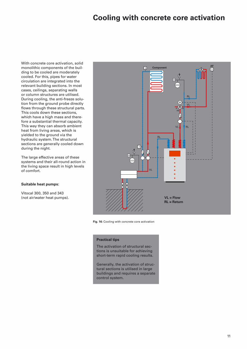
With concrete core activation, solidmonolithic components of the buil-ding to be cooled are moderatelycooled. For this, pipes for water circulation are integrated into the relevant building sections. In mostcases, ceilings, separating walls or column structures are utilised. During cooling, the anti-freeze solu-tion from the ground probe directlyflows through these structural parts.This cools down these sections,which have a high mass and there-fore a substantial thermal capacity.This way they can absorb ambientheat from living areas, which is yielded to the ground via the hydraulic system. The structural sections are generally cooled downduring the night.
The large effective areas of these systems and their all-round action inthe living space result in high levelsof comfort.
Suitable heat pumps:
Vitocal 300, 350 and 343(not air/water heat pumps).
Practical tips
The activation of structural sec-tions is unsuitable for achievingshort-term rapid cooling results.
Generally, the activation of struc-tural sections is utilised in largebuildings and requires a separatecontrol system.
Fig. 16: Cooling with concrete core activation
Subject to technical modifications9447 525 GB 10/2004
Viessmann offers
you a diverse
range of products,
which are uniform
in quality and
adaptable enough
to be able to meet
any demand and
any requirement
The Viessmann Group
The Viessmann Group employs approxi-mately 6800 staff worldwide and is oneof the foremost manufacturers of heat-ing equipment. For freestanding boilers,Viessmann is the most successful brandin Europe. The Viessmann brand standsfor competence and innovation. TheViessmann Group offers a comprehen-sive range of top-quality, high-tech products along with perfectly matchedmodular components. For all their diversity, our products haveone thing in common: a consistentlyhigh standard of quality that is reflectedin operational reliability, energy savings,environmental compatibility and user-friendliness.
Many of our developments point theway forward for the heating sector, bothin terms of conventional heating tech-nologies and in the field of renewableforms of energy, such as solar and heatpump technology.
In all our developments we pursue our philosophy of always achieving the greatest possible benefit: for our customers, the environment and ourpartners, the heating contractors.
The Viessmann Group:
Viessmann Werke
D-35107 Allendorf (Eder)
Tel: + 49 6452 70 - 0
Fax: + 49 6452 70 - 2780
www.viessmann.com
Viessmann UK Office:
Viessmann Limited
Hortonwood 30,Telford
Shropshire,TF1 7YP, GB
Tel: + 44 1952 675000
Fax: + 44 1952 675040
E-Mail: [email protected]
oil and gas fired
condensing boilers