Embed Size (px)
Citation preview
99
Software User GuideTopview Programmer A
Topview Programmer A
Software User Guide
Frontline Electronics Pvt Ltd.Pandian Street, Alagapuram, Salem - 636 016, Tamilnadu. India.
Ph : 0091 427 - 244 9238 / 243 1312. Fax : 0091 427 - 244 9010.
Email : [email protected]
www.Frontline-Electronics.com
Advanced Device Programmer For
Philips 8051 Microcontrollers

Software User Guide
98
Topview Programmer A
For Technical or Customer Support
You can reach Frontline Electronics Pvt, Ltd for the technical support and
application assistance in following ways:
Email questions to: [email protected]
Send questions by mail to:
Frontline Electronics Pvt Ltd.,
Pandian Street,
Alagapuram,
Salem - 636 016,
Tamilnadu,
India.
Phone :0091 427 244 9238 / 243 1312.
Fax :0091 427 244 9010.
Web site : www.Frontline-Electronics.com
Copyright © 2004 Frontline Electronics Pvt Ltd. All Rights Reserved.
Information in this document is subject to change without notice. No part of this
document may be reproduced or transmitted in any form or by any means,
electronic or mechanical, for any purpose without the express written permission
of Frontline Electronics Pvt Ltd.
Software User Guide
94
Topview Programmer A
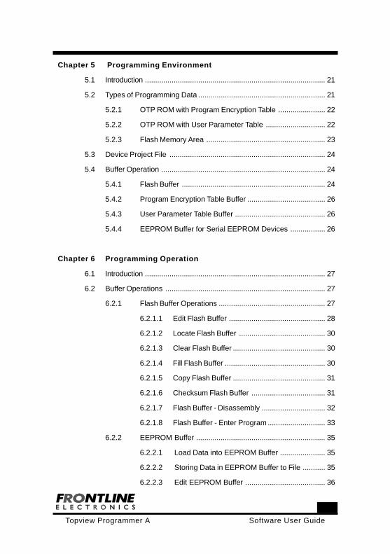
Contents
Chapter 1 Introduction
1.1 Welcome ............................................................................................ 1
1.2 Features of the programmer ................................................................ 1
1.3 Programming Operations .................................................................... 3
1.4 Hardware ............................................................................................ 4
1.5 Packaging ............................................................................................ 5
Chapter 2 Supported Devices
2.1 Introduction ......................................................................................... 7
2.2 List of supported Devices ................................................................... 7
2.2.1 Up-gradation of the Programmer ..................................... 10
Chapter 3 Getting Started
3.1 Introduction ....................................................................................... 13
3.2 System Requirements ....................................................................... 13
3.3 Installing Software ............................................................................. 13
3.4 Installing Hardware ............................................................................ 14
3.5 Programming Software ..................................................................... 15
3.6 Uninstalling Software ......................................................................... 16
Chapter 4 Programmer Setting
4.1 Introduction ........................................................................................ 17
4.2 Serial Port Setting .............................................................................. 17
4.3 Buffer and Programming Options ...................................................... 18
4.4 Verification ......................................................................................... 19
95
Software User GuideTopview Programmer A
Chapter 5 Programming Environment
5.1 Introduction ........................................................................................ 21
5.2 Types of Programming Data .............................................................. 21
5.2.1 OTP ROM with Program Encryption Table ....................... 22
5.2.2 OTP ROM with User Parameter Table ............................. 22
5.2.3 Flash Memory Area .......................................................... 23
5.3 Device Project File ............................................................................ 24
5.4 Buffer Operation ................................................................................ 24
5.4.1 Flash Buffer ...................................................................... 24
5.4.2 Program Encryption Table Buffer ...................................... 26
5.4.3 User Parameter Table Buffer ............................................ 26
5.4.4 EEPROM Buffer for Serial EEPROM Devices ................. 26
Chapter 6 Programming Operation
6.1 Introduction ........................................................................................ 27
6.2 Buffer Operations .............................................................................. 27
6.2.1 Flash Buffer Operations .................................................... 27
6.2.1.1 Edit Flash Buffer ............................................... 28
6.2.1.2 Locate Flash Buffer .......................................... 30
6.2.1.3 Clear Flash Buffer ............................................. 30
6.2.1.4 Fill Flash Buffer ................................................. 30
6.2.1.5 Copy Flash Buffer ............................................. 31
6.2.1.6 Checksum Flash Buffer .................................... 31
6.2.1.7 Flash Buffer - Disassembly ............................... 32
6.2.1.8 Flash Buffer - Enter Program ............................ 33
6.2.2 EEPROM Buffer ............................................................... 35
6.2.2.1 Load Data into EEPROM Buffer ...................... 35
6.2.2.2 Storing Data in EEPROM Buffer to File ........... 35
6.2.2.3 Edit EEPROM Buffer ....................................... 36
Software User Guide
96
Topview Programmer A
6.2.2.4 Locate EEPROM Buffer .................................. 36
6.2.2.5 Clear EEPROM Buffer ..................................... 37
6.2.2.6 Fill EEPROM Buffer ......................................... 37
6.2.2.7 Copy EEPROM Buffer ..................................... 38
6.2.2.8 Checksum EEPROM Buffer ............................ 38
6.3 Load Buffers ..................................................................................... 38
6.4 Save Buffers ...................................................................................... 42
6.5 Device Selection ............................................................................... 43
6.6 Auto programming Mode ................................................................... 50
6.6.1 Erase ................................................................................ 51
6.6.2 Program ............................................................................ 53
6.6.3 Verification ........................................................................ 53
6.6.4 Set Encryption Table Address ........................................... 54
6.6.5 Set User Parameter Table ................................................ 55
6.6.6 Set Device Configuration .................................................. 55
6.6.7 Set Boot Vector and Status Byte ...................................... 57
6.6.8 Set Protection Bits ............................................................ 58
6.6.9 Multiple Device Programming ........................................... 62
6.7 Erase Device ..................................................................................... 64
6.8 Blank Check Device .......................................................................... 66
6.9 Program the Device ........................................................................... 68
6.10 Read Device ...................................................................................... 70
6.11 Verify Device ...................................................................................... 71
6.12 Protect Device ................................................................................... 72
6.13 Initialize Device .................................................................................. 76
6.14 Program Encryption Table ................................................................. 77
6.15 Program User Parameter Table ......................................................... 78
6.16 Read User Parameter Table .............................................................. 79
6.17 Read and Display the Signature Byte of the Device ......................... 79
97
Software User GuideTopview Programmer A
6.18 Read and Display the Security Bit Status .......................................... 80
6.19 Cyclic Redundancy Check ................................................................. 81
6.20 Program Device Configuration .......................................................... 82
6.21 Program Boot Vector and Status Bytes ............................................. 83
Chapter 7 Programming the soldered Device in the Target Hardware
7.1 Introduction ........................................................................................ 85
7.2 ICP and ISP Modes ........................................................................... 85
7.3 Power on Reset Code Execution ....................................................... 88
7.4 Hardware Activate of the Boot Loader .............................................. 88
7.5 Boot ROM ......................................................................................... 89
7.6 Status Byte/Bit ................................................................................... 89
7.7 Boot Vector ........................................................................................ 90
7.8 Basic Requirements in Target Hardware to get ISP facility ................ 90
7.9 Connecting the Target Hardware to the Programmer ........................ 91
1
Software User GuideTopview Programmer A
1.1. Welcome:
Thank you for purchasing Topview Programmer A. The Topview Device
programmer is meant for programming many 8031 Der ivat ives
manufactured by the Philips Semiconductor. The list of devices supported
by this programmer is available elsewhere in this manual.
The programmer is an add-on card to the standard personal computer
through the serial port.
Suitable software is made available to make programming operations
simple, convenient and also interesting.
1.2 Features of the programmer:
Supports more than 75 popular and widely avai lable Phi l ips
Microcontrollers.
Also supports around 100 EEPROM devices from both Atmel and
Microchip.
Single 40pin ZIF socket to accommodate DIP devices.
Devices with operating voltages 3.3V and 5V can be programmed.
Facility also available to program through ICP (for LPC9XX series)
and ISP mode after soldering the device in the target board using a
10 pin cable. This cable is made available along with the programmer.
Ver i f icat ion at var ious vol tages can be done as per Phi l ips
specification.
Programmer can be upgraded to support new devices at your
premises.
LED indicators are provided for Power and Busy status.
Chapter 1. Introduction.
Software User Guide
2
Topview Programmer A
Programmer can be connected through serial port of the personal
computer.
The programmer is mounted in a sleek and eye catching wooden jewel
box.
Programmer comes with a separate power supply and, serial port
cable and also ICP/ISP programming cable.
Programming Features:
Supports both Binary and Hex formats.
Commands and functions as per Philips specification.
Major Commands are:
Erase.
Blank Check.
Protect the Device against copying.
Read the Device signature.
Read the Protection status.
Device Configuration.
Program Status Byte and Boot Vector.
Program Flash Area.
Program Encryption Table.
Program User Parameter Table.
Verify.
Cycle Redundancy Check.
Auto Programming mode to automate the selected commands.
Multiple Devices can be programmed.
Chapter 1. Introduction.
3
Software User GuideTopview Programmer A
Project management facility.
Verification at various voltages as per your choice.
You can read the flash memory contents as the program.
You can edit and assemble and modify your application code.
Facility to program EEPROM families, 24XX, 25XX and 93XX from
Atmel and Microchip.
1.3. Programming Operations:
The Topview Programmer A maintains separate buffer areas for selected
device’s flash memory, Program Encryption Table, User parameter Table,
Serial EEPROM in the programming environment. Initially you need to
transfer your target program code/data from the files into this buffer and
then program the selected device with these buffer contents.
When you keep your program code in the flash buffer, you can edit, modify
them as per your requirement. Even you can visualize the buffer contents
as the lines of program. This facility enables you to incorporate small
modifications without taking the code to the original development tools.
The Programmer also supports programming flash memory using ICP
and ISP modes. You can program the target device even after soldering
the same in the target hardware.
In short, the programming environment is total and complete in all respects
and you can confidentially use the programmer in your demanding
applications.
Chapter 1. Introduction.

Software User Guide
4
Topview Programmer A
1.4. Hardware:
The programmer consists of a PCB mounted in a sleek wooden box, a
separate power supply and all required cables.
The Power Supply provides a set of DC voltages like 9V @500mA and
18V @100mA. The programmer has on-board regulator to generate
operating voltage and the programming voltages.
The programmer sports a 40-pin ZIF socket to program DIP devices in
40, 20, 16 and 8 pins.
A connector marked as ‘ Power ‘ is used to connect the power supply to
the programmer and the termination of the connector is given here:
Pins 1 & 2 - 9V.
Pins 3 & 4 - Ground.
Pins 6 & 7 - 18V.
Similarly another connector, Serial port is meant for connecting the
programmer with the host personal computer through the serial port.
The connector terminations are given here:
Pin1 - NC.
Pin2 - RXD.
Pin3 - TXD.
Pin4 - NC.
Pin5 - Ground.
Pin6 - NC.
Pin7 - NC.
Pin8 - NC.
Pin9 - NC.
Chapter 1. Introduction.
5
Software User GuideTopview Programmer A
A switch, RESET is meant for resetting the programmer.
Another 10 pin connector, ISP / ICP Connector is used to program the
target microcontrollers soldered in the application hardware using either
ISP or ICP mode. For more information on this, refer the Chapter 7.
Programming the soldered Device in the Target Hardware.
Two point LEDs indicate Power On and Busy condi t ions of the
programmer.
1.5. Packaging:
Your package contains the following:
Programmer Hardware mounted in the sleek wooden box.
Power supply.
Serial port cable.
ICP/ISP programming cable.
Programmer user Guide.
CD containing programmer software and other useful information.
Chapter 1. Introduction.

Software User Guide
6
Topview Programmer A
7
Software User GuideTopview Programmer A
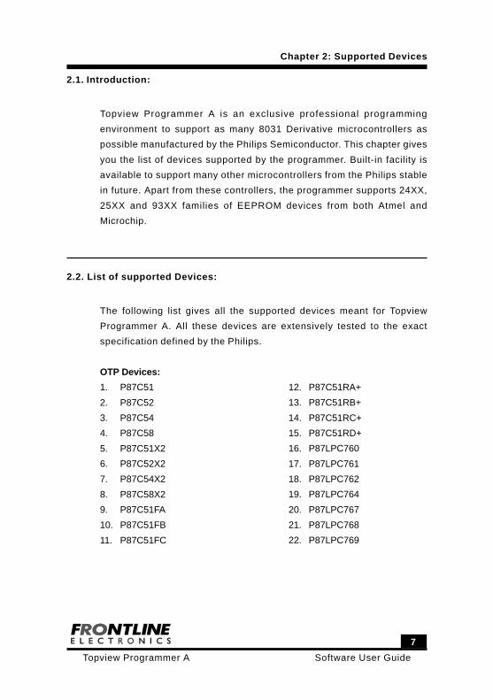
2.1. Introduction:
Topview Programmer A is an exclusive professional programming
environment to support as many 8031 Derivative microcontrollers as
possible manufactured by the Philips Semiconductor. This chapter gives
you the list of devices supported by the programmer. Built-in facility is
available to support many other microcontrollers from the Philips stable
in future. Apart from these controllers, the programmer supports 24XX,
25XX and 93XX families of EEPROM devices from both Atmel and
Microchip.
2.2. List of supported Devices:
The following list gives all the supported devices meant for Topview
Programmer A. All these devices are extensively tested to the exact
specification defined by the Philips.
OTP Devices:
1. P87C51
2. P87C52
3. P87C54
4. P87C58
5. P87C51X2
6. P87C52X2
7. P87C54X2
8. P87C58X2
9. P87C51FA
10. P87C51FB
11. P87C51FC
12. P87C51RA+
13. P87C51RB+
14. P87C51RC+
15. P87C51RD+
16. P87LPC760
17. P87LPC761
18. P87LPC762
19. P87LPC764
20. P87LPC767
21. P87LPC768
22. P87LPC769
Chapter 2: Supported Devices
Software User Guide
8
Topview Programmer A
Chapter 2: Supported Devices
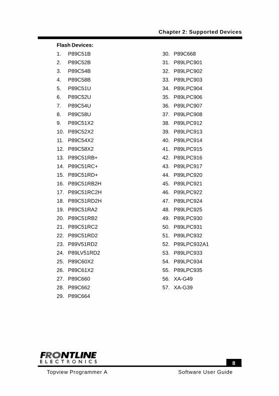
Flash Devices:
1. P89C51B
2. P89C52B
3. P89C54B
4. P89C58B
5. P89C51U
6. P89C52U
7. P89C54U
8. P89C58U
9. P89C51X2
10. P89C52X2
11. P89C54X2
12. P89C58X2
13. P89C51RB+
14. P89C51RC+
15. P89C51RD+
16. P89C51RB2H
17. P89C51RC2H
18. P89C51RD2H
19. P89C51RA2
20. P89C51RB2
21. P89C51RC2
22. P89C51RD2
23. P89V51RD2
24. P89LV51RD2
25. P89C60X2
26. P89C61X2
27. P89C660
28. P89C662
29. P89C664
30. P89C668
31. P89LPC901
32. P89LPC902
33. P89LPC903
34. P89LPC904
35. P89LPC906
36. P89LPC907
37. P89LPC908
38. P89LPC912
39. P89LPC913
40. P89LPC914
41. P89LPC915
42. P89LPC916
43. P89LPC917
44. P89LPC920
45. P89LPC921
46. P89LPC922
47. P89LPC924
48. P89LPC925
49. P89LPC930
50. P89LPC931
51. P89LPC932
52. P89LPC932A1
53. P89LPC933
54. P89LPC934
55. P89LPC935
56. XA-G49
57. XA-G39
9
Software User GuideTopview Programmer A
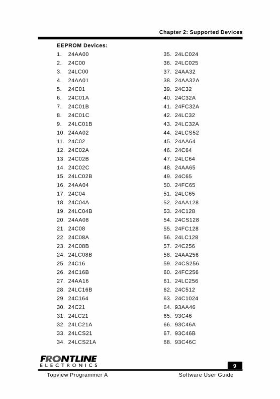
EEPROM Devices:
1. 24AA00
2. 24C00
3. 24LC00
4. 24AA01
5. 24C01
6. 24C01A
7. 24C01B
8. 24C01C
9. 24LC01B
10. 24AA02
11. 24C02
12. 24C02A
13. 24C02B
14. 24C02C
15. 24LC02B
16. 24AA04
17. 24C04
18. 24C04A
19. 24LC04B
20. 24AA08
21. 24C08
22. 24C08A
23. 24C08B
24. 24LC08B
25. 24C16
26. 24C16B
27. 24AA16
28. 24LC16B
29. 24C164
30. 24C21
31. 24LC21
32. 24LC21A
33. 24LCS21
34. 24LCS21A
35. 24LC024
36. 24LC025
37. 24AA32
38. 24AA32A
39. 24C32
40. 24C32A
41. 24FC32A
42. 24LC32
43. 24LC32A
44. 24LCS52
45. 24AA64
46. 24C64
47. 24LC64
48. 24AA65
49. 24C65
50. 24FC65
51. 24LC65
52. 24AA128
53. 24C128
54. 24CS128
55. 24FC128
56. 24LC128
57. 24C256
58. 24AA256
59. 24CS256
60. 24FC256
61. 24LC256
62. 24C512
63. 24C1024
64. 93AA46
65. 93C46
66. 93C46A
67. 93C46B
68. 93C46C
Chapter 2: Supported Devices
Software User Guide
10
Topview Programmer A
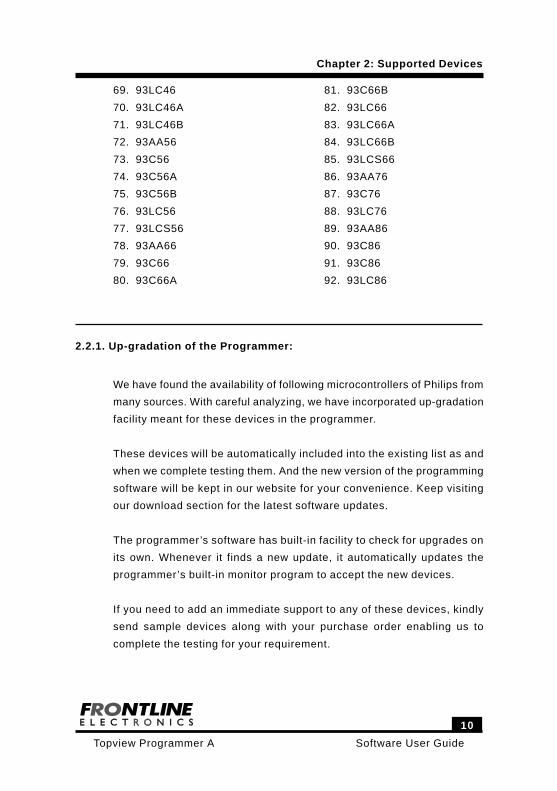
69. 93LC46
70. 93LC46A
71. 93LC46B
72. 93AA56
73. 93C56
74. 93C56A
75. 93C56B
76. 93LC56
77. 93LCS56
78. 93AA66
79. 93C66
80. 93C66A
81. 93C66B
82. 93LC66
83. 93LC66A
84. 93LC66B
85. 93LCS66
86. 93AA76
87. 93C76
88. 93LC76
89. 93AA86
90. 93C86
91. 93C86
92. 93LC86
Chapter 2: Supported Devices
2.2.1. Up-gradation of the Programmer:
We have found the availability of following microcontrollers of Philips from
many sources. With careful analyzing, we have incorporated up-gradation
facility meant for these devices in the programmer.
These devices will be automatically included into the existing list as and
when we complete testing them. And the new version of the programming
software will be kept in our website for your convenience. Keep visiting
our download section for the latest software updates.
The programmer’s software has built-in facility to check for upgrades on
its own. Whenever it finds a new update, it automatically updates the
programmer’s built-in monitor program to accept the new devices.
If you need to add an immediate support to any of these devices, kindly
send sample devices along with your purchase order enabling us to
complete the testing for your requirement.
11
Software User GuideTopview Programmer A
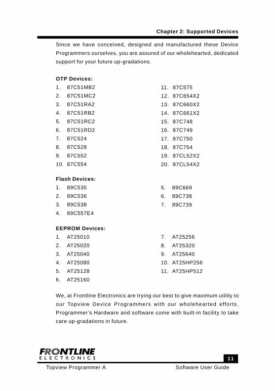
Since we have conceived, designed and manufactured these Device
Programmers ourselves, you are assured of our wholehearted, dedicated
support for your future up-gradations.
OTP Devices:
1. 87C51MB2
2. 87C51MC2
3. 87C51RA2
4. 87C51RB2
5. 87C51RC2
6. 87C51RD2
7. 87C524
8. 87C528
9. 87C552
10. 87C554
11. 87C575
12. 87C654X2
13. 87C660X2
14. 87C661X2
15. 87C748
16. 87C749
17. 87C750
18. 87C754
19. 87CL52X2
20. 87CL54X2
Flash Devices:
1. 89C535
2. 89C536
3. 89C538
4. 89C557E4
5. 89C669
6. 89C738
7. 89C739
EEPROM Devices:
1. AT25010
2. AT25020
3. AT25040
4. AT25080
5. AT25128
6. AT25160
7. AT25256
8. AT25320
9. AT25640
10. AT25HP256
11. AT25HP512
Chapter 2: Supported Devices
We, at Frontline Electronics are trying our best to give maximum utility to
our Topview Device Programmers with our wholehearted efforts.
Programmer’s Hardware and software come with built-in facility to take
care up-gradations in future.
Software User Guide
12
Topview Programmer A
Chapter 2: Supported Devices
As of now, this Topview Programmer A is the most advanced device
Programmer available for this cost anywhere.
If by chance, any of the future Philips device demands any special
facility not possible in the existing hardware and software, we, at
Frontline Electronics don’t assume any responsibility for the same.
13
Software User GuideTopview Programmer A
Chapter 3. Getting Started
3.1. Introduction:
This chapter gives you the complete picture on the programmer and takes
you to install the same in your personal computer.
3.2. System Requirements:
The Minimum configuration is
Personal computer with win 9X/2000/XP.
A Serial port.
Free hard Disk space of about 7MB.
Internet Explorer of version 4.0 or above.
3.3. Installing Software:
Insert the CDROM supplied with the programmer pack. If the CD drive is
enabled with ‘Auto Execution’ facility, a batch file starts executing and
the Frontline Electronics’ Home page opens up. A link to Topview
Programmer A. exe is provided in the first page. Just click the link to
install Topview Programmer A for Philips Controllers software.
Otherwise, run the executable file, Setup.exe available in the folder,
Topview Programmer A. You may select the destination path during
installation.
The installer package will guide you through the installation process.

Software User Guide
14
Topview Programmer A
Chapter 3. Getting Started
3.4. Installing Hardware:
Connect the power supply to the programmer hardware at power
connector.
Connect the programmer to the host computer using serial port cable.
Switch on the power supply to the programmer.
Execute the application (Topview Programmer A) from the Start
Program Topview Programmer A. An opening screen comes up with
an About dialog box.
If the PC is not able to establish communication through the serial port
(COM2 is default), it will give an error message, ‘Cannot Establish
Communication’. This indicates that the assigned COM port is not
available for this application.
Now, select the Settings option and use Serial Port to change the COM
port to start communication. If the selected COM port is free, the
communication is established and the device programming can be started.
15
Software User GuideTopview Programmer A
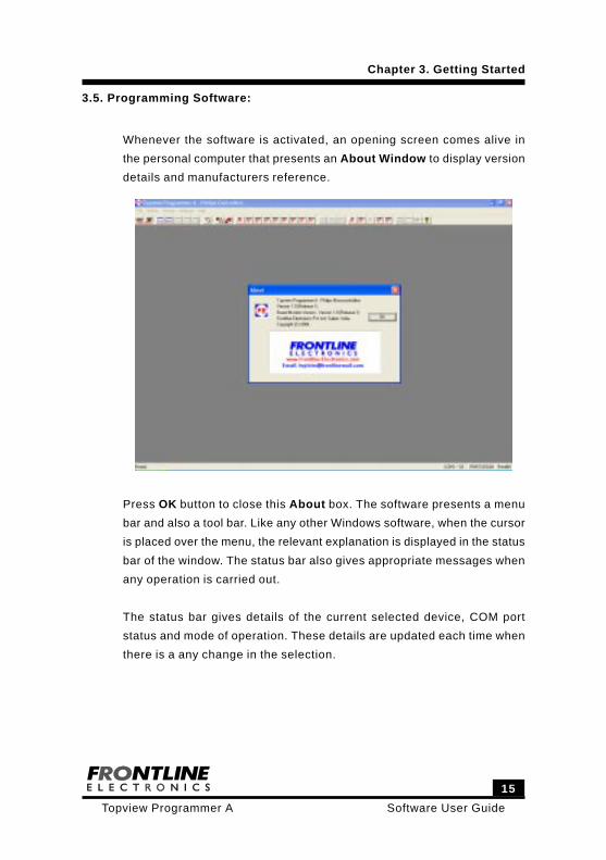
3.5. Programming Software:
Whenever the software is activated, an opening screen comes alive in
the personal computer that presents an About Window to display version
details and manufacturers reference.
Press OK button to close this About box. The software presents a menu
bar and also a tool bar. Like any other Windows software, when the cursor
is placed over the menu, the relevant explanation is displayed in the status
bar of the window. The status bar also gives appropriate messages when
any operation is carried out.
The status bar gives details of the current selected device, COM port
status and mode of operation. These details are updated each time when
there is a any change in the selection.
Chapter 3. Getting Started
Software User Guide
16
Topview Programmer A
3.6. Uninstalling Software:
Use control panel of windows operating system to remove the
programming software from your computer.
Chapter 3. Getting Started
17
Software User GuideTopview Programmer A
4.1. Introduction:
This chapter is for def ining var ious sett ings meant for di f ferent
programming operations like Auto Programming mode, multiple device
programming and etc. These features basically combine many steps of
programming into a single task to save your time during repeated
programming needs.
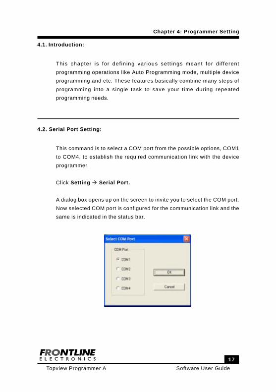
4.2. Serial Port Setting:
This command is to select a COM port from the possible options, COM1
to COM4, to establish the required communication link with the device
programmer.
Click Setting Serial Port.
A dialog box opens up on the screen to invite you to select the COM port.
Now selected COM port is configured for the communication link and the
same is indicated in the status bar.
Chapter 4: Programmer Setting
Software User Guide
18
Topview Programmer A
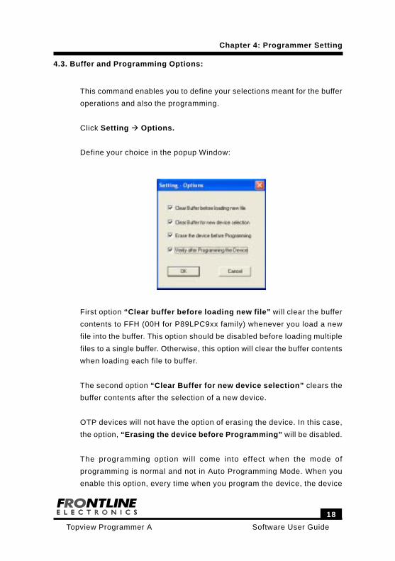
4.3. Buffer and Programming Options:
This command enables you to define your selections meant for the buffer
operations and also the programming.
Click Setting Options.
Define your choice in the popup Window:
First option “Clear buffer before loading new file” will clear the buffer
contents to FFH (00H for P89LPC9xx family) whenever you load a new
file into the buffer. This option should be disabled before loading multiple
files to a single buffer. Otherwise, this option will clear the buffer contents
when loading each file to buffer.
The second option “Clear Buffer for new device selection” clears the
buffer contents after the selection of a new device.
OTP devices will not have the option of erasing the device. In this case,
the option, “Erasing the device before Programming” will be disabled.
The programming option wil l come into effect when the mode of
programming is normal and not in Auto Programming Mode. When you
enable this option, every time when you program the device, the device
Chapter 4: Programmer Setting
19
Software User GuideTopview Programmer A
will be erased before getting programmed.
Similarly, the devices are verified with the contents of the buffer when
you enable the “Verify after Programming” option.
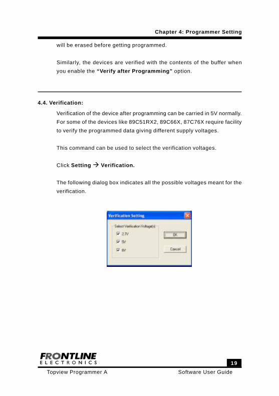
4.4. Verification:
Verification of the device after programming can be carried in 5V normally.
For some of the devices like 89C51RX2, 89C66X, 87C76X require facility
to verify the programmed data giving different supply voltages.
This command can be used to select the verification voltages.
Click Setting Verification.
The following dialog box indicates all the possible voltages meant for the
verification.
Chapter 4: Programmer Setting

Software User Guide
20
Topview Programmer A
21
Software User GuideTopview Programmer A
Chapter 5: Programming Environment
5.1. Introduction:
The programmer maintains a buffer area equivalent to target controller ’s
flash memory area, Program Encryption Table, User Parameter Table
and Target serial EEPROM area. Keeping your program code or data
inside of the respective buffer, you can edit, modify as per your
requirement before programming. You can also incorporate changes in
your target program code without going back to the original development
tools thanks to the built-in assembling facility. This is one important facility
required during field up-gradation of the finished applications.
5.2. Types of Programming Data:
You can load any specific buffer with the program/ data from any file.
Program can be loaded in both Intel Hex and Binary formats. The
programming code can be loaded from any file to any specific buffer or
to many buffers at the same time using both of these formats.
In the Intel Hex format, the information on address of the locations comes
in the file itself. In Binary format, you need to Key in respective address
during buffer operations.
Following are the types of programming code/ data handled by the device
programmer:
One Time Programmable ROM with Program Encryption Table.
One Time Programmable ROM with User Parameter Table.
Flash memory area.
Software User Guide
22
Topview Programmer A
5.2.1. OTP ROM with Program Encryption Table:
The OTP devices of the Philips microcontrollers except P87LPC76X have
OTP memory area to store Program code and 32 / 64 bytes of Program
Encryption Table.
The OTP memory starts from 0000H and the ending address varies
according to the device capacity. The address of the Program Encryption
Table starts from the next address after OTP area.
For an example, in P87C51, the OTP memory of 4K starts from 0000H to
0FFFH and the Program Encryption Table is available from 1000H to
103FH. When you load the buffer meant for this device using the file, all
the program code between 0000H and 0FFFH is transferred to the flash
buffer and the data between 1000H and 103FH will be made available in
the buffer of Program Encryption Table.
Similarly during file storage operation, contents of all the buffers will be
stored in the respective memory location meant for that selected
microcontroller.
5.2.2. OTP ROM with User Parameter Table:
The P87LPC76X family devices have OTP ROM and 32 bytes of User
Parameter Table.
The program memory address starts from 0000H.
The ending address depends upon the capacity of the selected device.
The actual physical address of User Parameter Table lies between FCE0H
and FCFFH.
In Hex file format, the actual address of the User Parameter Table is
Chapter 5: Programming Environment
23
Software User GuideTopview Programmer A
always defined as the one from FCE0H to FCFFH. When using binary
format, the actual address is mapped to the location immediately after
the program memory space.
As an example, consider the device, P87LPC760, which has 1K Bytes of
program memory and 32 bytes of User Parameter Table.
For Intel Hex format:
Program Memory : 0000H to 03FFH.
User Parameter Table : FCE0H to FCFFH.
User Configuration Register 1 : FD00H.
User Configuration Register 2 : FD01H.
When you use Binary file format:
Program Memory : 0000H to 03FFH.
User Parameter Table : 0400H to 041FH.
User Configuration Register 1 : 0420H.
User Configuration Register 2 : 0421H.
During buffer storing and loading operations, respective memory areas
are properly saved or read from the files automatically.
5.2.3. Flash Memory Area:
Normally flash memory of any microcontroller is mapped into the program
memory space. Most of the time, this memory contains only programming
code along with required data.
Chapter 5: Programming Environment
Software User Guide
24
Topview Programmer A
5.3. Device Project File:
The programmer gives you the facility to keep all the relevant program
and data information generated for the specific device in an exclusive
project file. So, you need not worry about keeping flash memory, User
Parameter Table and Program Encryption Table at their respective
address blocks.
You can easily save device project file and load the same from files using
simple commands.
5.4. Buffer Operation:
The programming environment sports few buffers, which play an important
role during programming.
Available Buffers are:
Flash Buffer.
Program Encryption Table Buffer.
User Parameter Table Buffer.
EEPROM Buffer for serial EEPROM device.
5.4.1. Flash Buffer:
Normally, the buffer space will be made equal to the size of the selected
device’s flash memory capacity.
For an example, for the device P89C51, the buffer space goes up to 4K
(0FFFH). If the target file exceeds this space, an error message will be
Chapter 5: Programming Environment

25
Software User GuideTopview Programmer A
duly displayed for your convenience.
During programming, you may want to load your target program file into
this buffer space and then you may modify / correct the contents as per
your needs.
For your convenience, the buffer provides a “Single line Assembler” to
carry out these modifications with ease and confidence.
Another facility is, the buffer helps you to keep programming data from
many files in order. You can load these files into the buffer and verify the
whole lot and then program the target device in a single shot.
Buffer supports editing (In both Hex and ASCII), locating a byte, clearing,
filling, copying operation and also generates a checksum. All these
operations are explained in the detail in subsequent pages.
Another interesting facility using different colours is made available in
the buffer to indicate certain operations.
Normally the buffer contents are displayed in the black color. When a file
is loaded into the buffer, the colour changes to blue.
When you carry out editing in the contents of the buffer, the edited portion
is displayed in red colour. When you load the buffer from the flash area
of the selected device, that portion is displayed in green.
So with a little experience on the usage of different colours for buffer
functions, the colouring will assist you very much during program
development / debugging.
The buffer also sports a disassembly facility. When you activate this,
contents of the buffer will be displayed as program rather than as data
and you can see the actual program code in mnemonics. At this stage,
Chapter 5: Programming Environment
Software User Guide
26
Topview Programmer A
you can edit your program code or insert new program lines using built-in
single line assembler.
5.4.2. Program Encryption Table Buffer:
For some OTP devices, Philips provides a Program Encryption Table of
64/32 bytes in length.
A separate buffer is made available for this table. Like flash buffer, this
also has all the features except the disassembly facility since it contains
only data.
5.4.3. User Parameter Table Buffer:
In P87LPC76X family of controllers, this is an area of 32 bytes in the
memory meant for keeping User Parameter Table. This User Parameter
Table lies between FCE0H and FCFFH.
An exclusive buffer is made available for this table.
Like other buffers, this has all the features except the disassembly facility.
5.4.4. EEPROM Buffer for Serial EEPROM Devices:
Depends upon the selected EEPROM device, a suitable buffer area is
available during programming operations.
Chapter 5: Programming Environment

27
Software User GuideTopview Programmer A
6.1. Introduction:
Now you are going to know all the operations required to program the
selected device. During programming, memory buffers play an important
role in the programming functions.
Working knowledge on all the operations of these buffers will make your
programming tasks as easy and comfortable.
You may need to refer the chapter 4 to know about different setting
required to start the programming operations.
6.2. Buffer Operations:
As you know, programmer provides many buffers to keep track of flash
programming code, Program Encryption Table, User Parameter Table
meant for the microcontrollers as well as an exclusive buffer for serial
EEPROM devices.
In the following paragraphs, you are going to see more about various
operations meant for these buffers.
6.2.1. Flash Buffer Operations:
The Flash Buffer Supports the Following Functions:
Edit Flash Buffer.
Locate Flash Buffer.
Clear Flash Buffer.
Fill Flash Buffer.
Chapter 6. Programming Operation
Software User Guide
28
Topview Programmer A
Copy Flash Buffer.
Checksum Flash Buffer.
Flash Buffer - Disassembly.
Flash Buffer - Enter Program.
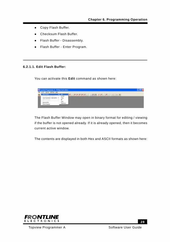
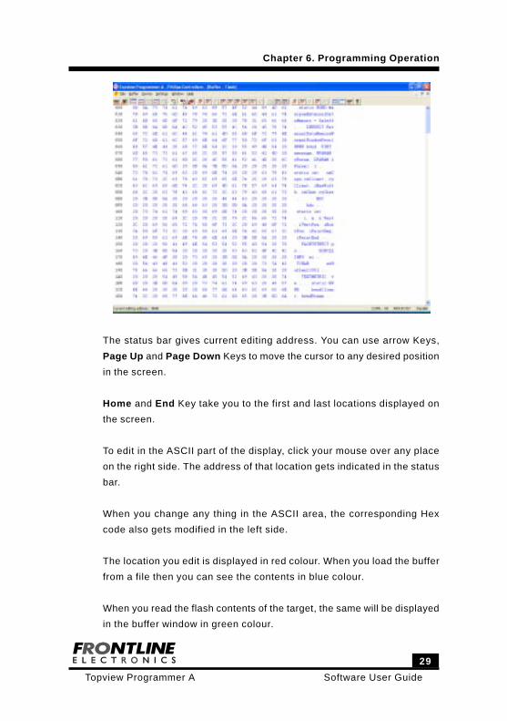
6.2.1.1. Edit Flash Buffer:
You can activate this Edit command as shown here:
The Flash Buffer Window may open in binary format for editing / viewing
if the buffer is not opened already. If it is already opened, then it becomes
current active window.
The contents are displayed in both Hex and ASCII formats as shown here:
Chapter 6. Programming Operation
29
Software User GuideTopview Programmer A
The status bar gives current editing address. You can use arrow Keys,
Page Up and Page Down Keys to move the cursor to any desired position
in the screen.
Home and End Key take you to the first and last locations displayed on
the screen.
To edit in the ASCII part of the display, click your mouse over any place
on the right side. The address of that location gets indicated in the status
bar.
When you change any thing in the ASCII area, the corresponding Hex
code also gets modified in the left side.
The location you edit is displayed in red colour. When you load the buffer
from a file then you can see the contents in blue colour.
When you read the flash contents of the target, the same will be displayed
in the buffer window in green colour.
Chapter 6. Programming Operation
Software User Guide
30
Topview Programmer A
When you clear the buffer using Clear command, the contents get black
colour.
6.2.1.2. Locate Flash Buffer:
Use this command to set the starting address for the flash Buffer. When
you activate this command, small dialog box opens upon the screen to
get the address.
This Locate command can also be activated by double clicking over any
address field displayed at the left side of the window. You can enter the
right address in the pop up window. Then the screen gets updated with
the data starting from that given address.
6.2.1.3. Clear Flash Buffer:
When you activate this command, you can notice all the contents of the
flash buffer becoming FFH (00H for P89LPC9xx family) and change the
colour to black to indicate the completion of the operation.
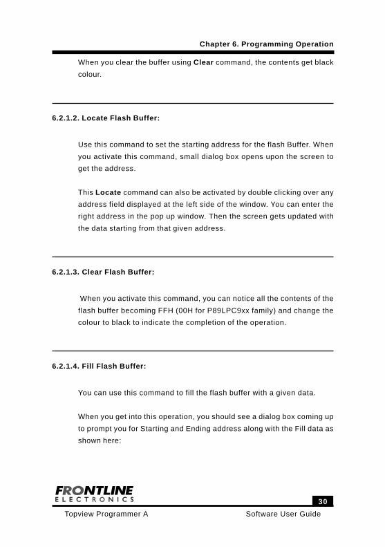
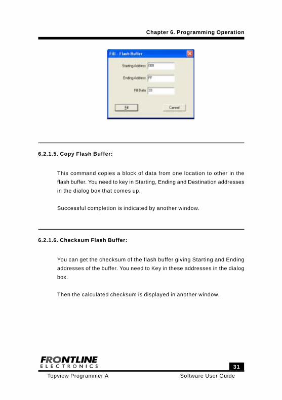
6.2.1.4. Fill Flash Buffer:
You can use this command to fill the flash buffer with a given data.
When you get into this operation, you should see a dialog box coming up
to prompt you for Starting and Ending address along with the Fill data as
shown here:
Chapter 6. Programming Operation
31
Software User GuideTopview Programmer A
Chapter 6. Programming Operation
6.2.1.5. Copy Flash Buffer:
This command copies a block of data from one location to other in the
flash buffer. You need to key in Starting, Ending and Destination addresses
in the dialog box that comes up.
Successful completion is indicated by another window.
6.2.1.6. Checksum Flash Buffer:
You can get the checksum of the flash buffer giving Starting and Ending
addresses of the buffer. You need to Key in these addresses in the dialog
box.
Then the calculated checksum is displayed in another window.
Software User Guide
32
Topview Programmer A
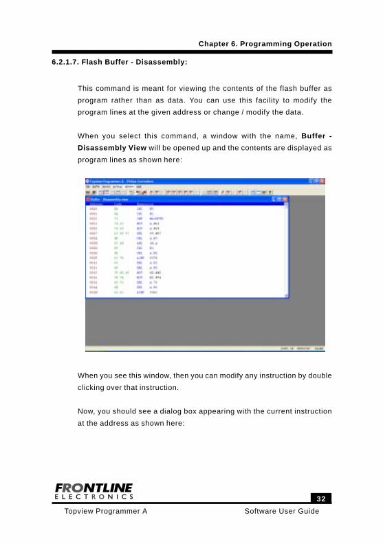
6.2.1.7. Flash Buffer - Disassembly:
This command is meant for viewing the contents of the flash buffer as
program rather than as data. You can use this facility to modify the
program lines at the given address or change / modify the data.
When you select this command, a window with the name, Buffer -
Disassembly View will be opened up and the contents are displayed as
program lines as shown here:
When you see this window, then you can modify any instruction by double
clicking over that instruction.
Now, you should see a dialog box appearing with the current instruction
at the address as shown here:
Chapter 6. Programming Operation
33
Software User GuideTopview Programmer A
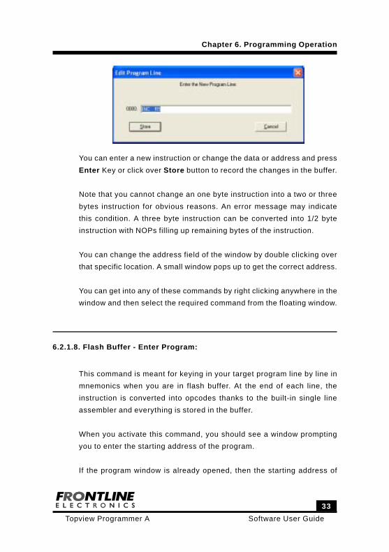
You can enter a new instruction or change the data or address and press
Enter Key or click over Store button to record the changes in the buffer.
Note that you cannot change an one byte instruction into a two or three
bytes instruction for obvious reasons. An error message may indicate
this condition. A three byte instruction can be converted into 1/2 byte
instruction with NOPs filling up remaining bytes of the instruction.
You can change the address field of the window by double clicking over
that specific location. A small window pops up to get the correct address.
You can get into any of these commands by right clicking anywhere in the
window and then select the required command from the floating window.
6.2.1.8. Flash Buffer - Enter Program:
This command is meant for keying in your target program line by line in
mnemonics when you are in flash buffer. At the end of each line, the
instruction is converted into opcodes thanks to the built-in single line
assembler and everything is stored in the buffer.
When you activate this command, you should see a window prompting
you to enter the starting address of the program.
If the program window is already opened, then the starting address of
Chapter 6. Programming Operation
Software User Guide
34
Topview Programmer A
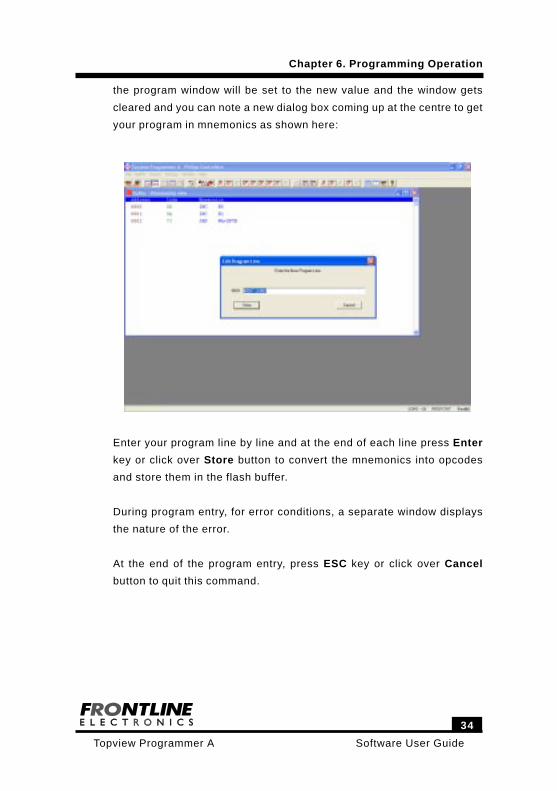
the program window will be set to the new value and the window gets
cleared and you can note a new dialog box coming up at the centre to get
your program in mnemonics as shown here:
Enter your program line by line and at the end of each line press Enter
key or click over Store button to convert the mnemonics into opcodes
and store them in the flash buffer.
During program entry, for error conditions, a separate window displays
the nature of the error.
At the end of the program entry, press ESC key or click over Cancel
button to quit this command.
Chapter 6. Programming Operation
35
Software User GuideTopview Programmer A
6.2.2. EEPROM Buffer:
The programmer maintains a buffer space to process the data meant for
the serial EEPROM devices. This buffer will be activated only when the
EEPROM devices are selected for programming. For microcontrollers,
this will not be activated.
Both Hex and Binary format data files can be read into this buffer from
the disk. The contents of this buffer can also be saved in the disk.
Following commands enable you to interact with this buffer during
programming operations.
Edit.
Locate.
Clear.
Fill.
Copy
Checksum.
6.2.2.1. Load Data into EEPROM Buffer:
A file can be loaded into the EEPROM buffer by using Load File command
in the File menu. Two file formats are supported here to load the data
into the EEPROM buffer.
6.2.2.2. Storing Data in EEPROM Buffer to File:
The contents of EEPROM buffer can be stored in a file in either Intel Hex
or Binary format using Save as … command from File menu.
Chapter 6. Programming Operation
Software User Guide
36
Topview Programmer A
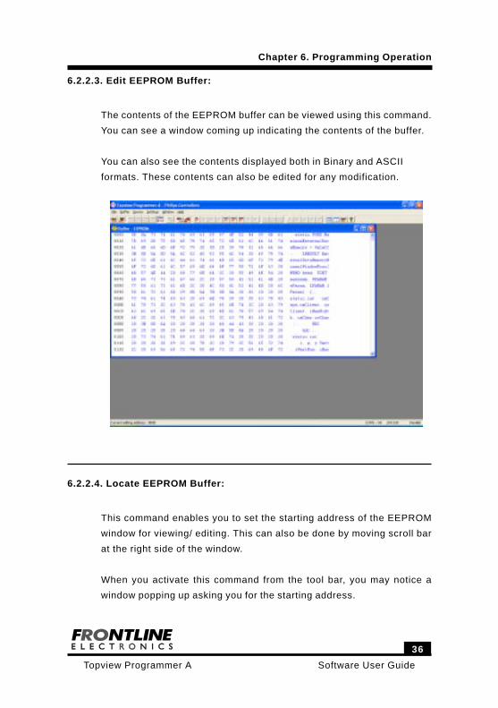
6.2.2.3. Edit EEPROM Buffer:
The contents of the EEPROM buffer can be viewed using this command.
You can see a window coming up indicating the contents of the buffer.
You can also see the contents displayed both in Binary and ASCII
formats. These contents can also be edited for any modification.
6.2.2.4. Locate EEPROM Buffer:
This command enables you to set the starting address of the EEPROM
window for viewing/ editing. This can also be done by moving scroll bar
at the right side of the window.
When you activate this command from the tool bar, you may notice a
window popping up asking you for the starting address.
Chapter 6. Programming Operation
37
Software User GuideTopview Programmer A
Key in the required address and complete the command to get the buffer
with the correct address.
6.2.2.5. Clear EEPROM Buffer:
By using this command, you can clear the contents of the EEPROM buffer
to FFH and the colour of the contents will become black.
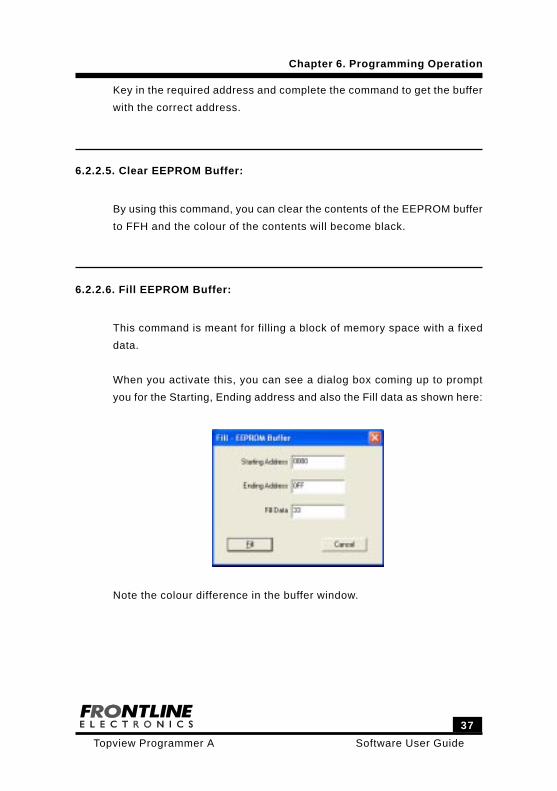
6.2.2.6. Fill EEPROM Buffer:
This command is meant for filling a block of memory space with a fixed
data.
When you activate this, you can see a dialog box coming up to prompt
you for the Starting, Ending address and also the Fill data as shown here:
Note the colour difference in the buffer window.
Chapter 6. Programming Operation
Software User Guide
38
Topview Programmer A
6.2.2.7. Copy EEPROM Buffer:
This command copies the contents from one area to another area of the
EEPROM buffer.
When getting into this operation, a dialog box comes up to get addresses
of Starting, Ending and Destination meant for the blocks.
Successful operation is indicated by another small window.
6.2.2.8. Checksum EEPROM Buffer:
This command may be used to find the Checksum of the EEPROM buffer
contents.
When the command is selected, a dialog box gets required addresses
and another window indicates the calculated Checksum.
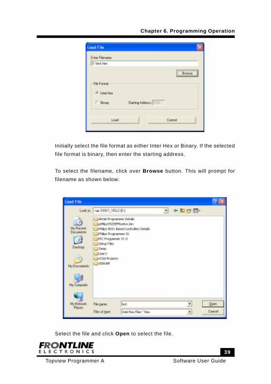
6.3. Load Buffers:
Select Load File command from File menu. This will open a dialog box
as shown below (for the devices having only flash memory):
Chapter 6. Programming Operation
39
Software User GuideTopview Programmer A
Initially select the file format as either Inter Hex or Binary. If the selected
file format is binary, then enter the starting address.
To select the filename, click over Browse button. This will prompt for
filename as shown below:
Select the file and click Open to select the file.
Chapter 6. Programming Operation
Software User Guide
40
Topview Programmer A
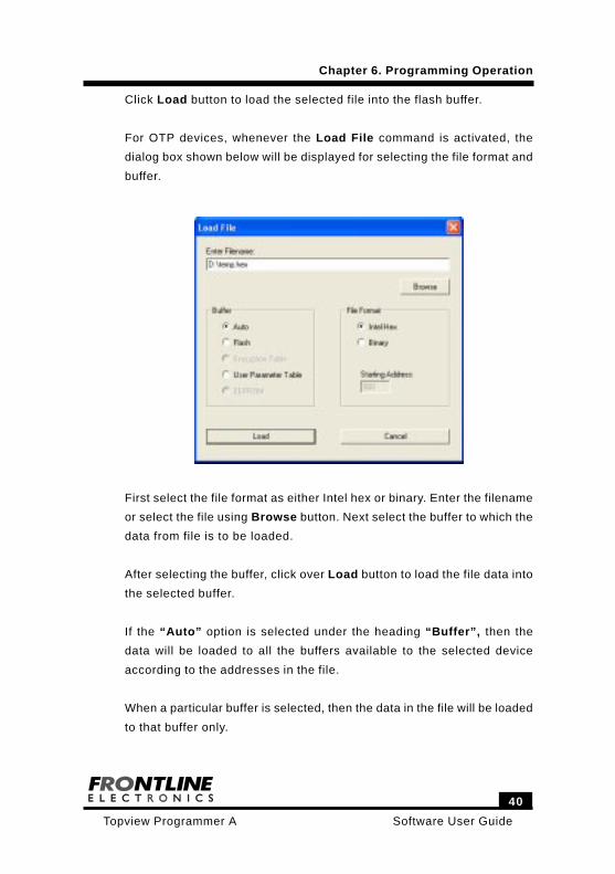
Click Load button to load the selected file into the flash buffer.
For OTP devices, whenever the Load File command is activated, the
dialog box shown below will be displayed for selecting the file format and
buffer.
First select the file format as either Intel hex or binary. Enter the filename
or select the file using Browse button. Next select the buffer to which the
data from file is to be loaded.
After selecting the buffer, click over Load button to load the file data into
the selected buffer.
If the “Auto” option is selected under the heading “Buffer”, then the
data will be loaded to all the buffers available to the selected device
according to the addresses in the file.
When a particular buffer is selected, then the data in the file will be loaded
to that buffer only.
Chapter 6. Programming Operation
41
Software User GuideTopview Programmer A
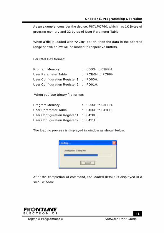
As an example, consider the device, P87LPC760, which has 1K Bytes of
program memory and 32 bytes of User Parameter Table.
When a file is loaded with “Auto” option, then the data in the address
range shown below will be loaded to respective buffers.
For Intel Hex format:
Program Memory : 0000H to 03FFH.
User Parameter Table : FCE0H to FCFFH.
User Configuration Register 1 : FD00H.
User Configuration Register 2 : FD01H.
When you use Binary file format:
Program Memory : 0000H to 03FFH.
User Parameter Table : 0400H to 041FH.
User Configuration Register 1 : 0420H.
User Configuration Register 2 : 0421H.
The loading process is displayed in window as shown below:
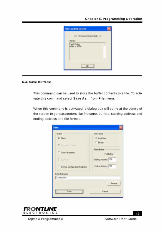
After the completion of command, the loaded details is displayed in a
small window.
Chapter 6. Programming Operation
Software User Guide
42
Topview Programmer A
6.4. Save Buffers:
This command can be used to store the buffer contents to a file. To acti-
vate this command select Save As… from File menu.
When this command is activated, a dialog box will come at the centre of
the screen to get parameters like filename, buffers, starting address and
ending address and file format.
Chapter 6. Programming Operation
43
Software User GuideTopview Programmer A
Here you can select full flash buffer area or a part. However, for both
Encryption Table and User Parameter Table only full buffer can be stored
in a file.
After selecting the buffers and file format, enter the address range and
filename. Use Browse button to select the existing file.
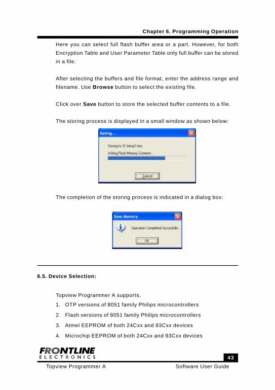
Click over Save button to store the selected buffer contents to a file.
The storing process is displayed in a small window as shown below:
The completion of the storing process is indicated in a dialog box:
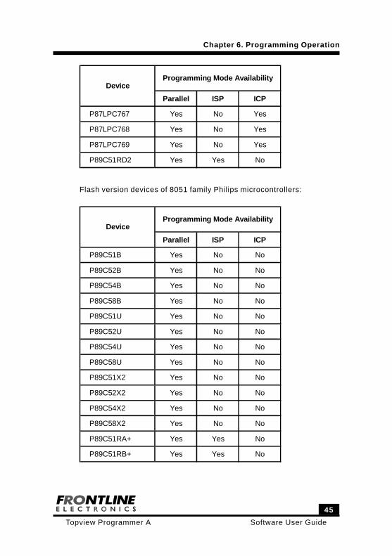
6.5. Device Selection:
Topview Programmer A supports,
1. OTP versions of 8051 family Philips microcontrollers
2. Flash versions of 8051 family Philips microcontrollers
3. Atmel EEPROM of both 24Cxx and 93Cxx devices
4. Microchip EEPROM of both 24Cxx and 93Cxx devices
Chapter 6. Programming Operation
Software User Guide
44
Topview Programmer A
The microcontrollers can be programmed in Parallel or ISP or ICP mode
as applicable to the selected device.
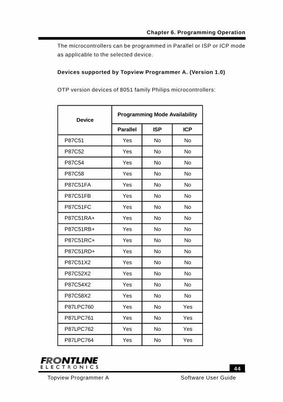
Devices supported by Topview Programmer A. (Version 1.0)
OTP version devices of 8051 family Philips microcontrollers:
Parallel ISP ICP
P87C51 Yes No No
P87C52 Yes No No
P87C54 Yes No No
P87C58 Yes No No
P87C51FA Yes No No
P87C51FB Yes No No
P87C51FC Yes No No
P87C51RA+ Yes No No
P87C51RB+ Yes No No
P87C51RC+ Yes No No
P87C51RD+ Yes No No
P87C51X2 Yes No No
P87C52X2 Yes No No
P87C54X2 Yes No No
P87C58X2 Yes No No
P87LPC760 Yes No Yes
P87LPC761 Yes No Yes
P87LPC762 Yes No Yes
P87LPC764 Yes No Yes
DeviceProgramming Mode Availability
Chapter 6. Programming Operation
45
Software User GuideTopview Programmer A
Parallel ISP ICP
P87LPC767 Yes No Yes
P87LPC768 Yes No Yes
P87LPC769 Yes No Yes
P89C51RD2 Yes Yes No
DeviceProgramming Mode Availability
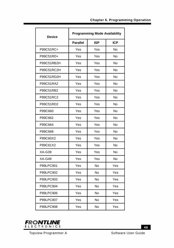
Flash version devices of 8051 family Philips microcontrollers:
Parallel ISP ICP
P89C51B Yes No No
P89C52B Yes No No
P89C54B Yes No No
P89C58B Yes No No
P89C51U Yes No No
P89C52U Yes No No
P89C54U Yes No No
P89C58U Yes No No
P89C51X2 Yes No No
P89C52X2 Yes No No
P89C54X2 Yes No No
P89C58X2 Yes No No
P89C51RA+ Yes Yes No
P89C51RB+ Yes Yes No
DeviceProgramming Mode Availability
Chapter 6. Programming Operation
Software User Guide
46
Topview Programmer A
Parallel ISP ICP
P89C51RC+ Yes Yes No
P89C51RD+ Yes Yes No
P89C51RB2H Yes Yes No
P89C51RC2H Yes Yes No
P89C51RD2H Yes Yes No
P89C51RA2 Yes Yes No
P89C51RB2 Yes Yes No
P89C51RC2 Yes Yes No
P89C51RD2 Yes Yes No
P89C660 Yes Yes No
P89C662 Yes Yes No
P89C664 Yes Yes No
P89C668 Yes Yes No
P89C60X2 Yes Yes No
P89C61X2 Yes Yes No
XA-G39 Yes Yes No
XA-G49 Yes Yes No
P89LPC901 Yes No Yes
P89LPC902 Yes No Yes
P89LPC903 Yes No Yes
P89LPC904 Yes No Yes
P89LPC906 Yes No Yes
P89LPC907 Yes No Yes
P89LPC908 Yes No Yes
DeviceProgramming Mode Availability
Chapter 6. Programming Operation
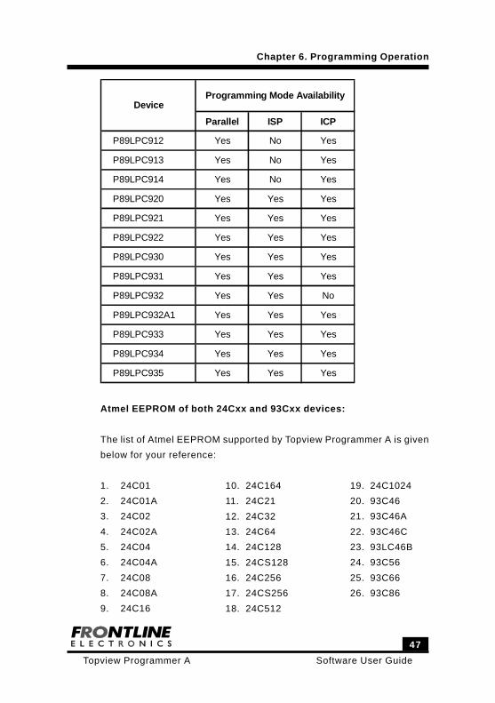
47
Software User GuideTopview Programmer A
Parallel ISP ICP
P89LPC912 Yes No Yes
P89LPC913 Yes No Yes
P89LPC914 Yes No Yes
P89LPC920 Yes Yes Yes
P89LPC921 Yes Yes Yes
P89LPC922 Yes Yes Yes
P89LPC930 Yes Yes Yes
P89LPC931 Yes Yes Yes
P89LPC932 Yes Yes No
P89LPC932A1 Yes Yes Yes
P89LPC933 Yes Yes Yes
P89LPC934 Yes Yes Yes
P89LPC935 Yes Yes Yes
DeviceProgramming Mode Availability
Atmel EEPROM of both 24Cxx and 93Cxx devices:
The list of Atmel EEPROM supported by Topview Programmer A is given
below for your reference:
1. 24C01
2. 24C01A
3. 24C02
4. 24C02A
5. 24C04
6. 24C04A
7. 24C08
8. 24C08A
9. 24C16
Chapter 6. Programming Operation
10. 24C164
11. 24C21
12. 24C32
13. 24C64
14. 24C128
15. 24CS128
16. 24C256
17. 24CS256
18. 24C512
19. 24C1024
20. 93C46
21. 93C46A
22. 93C46C
23. 93LC46B
24. 93C56
25. 93C66
26. 93C86
Software User Guide
48
Topview Programmer A
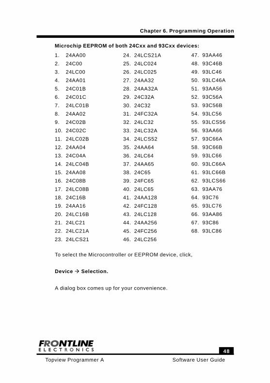
To select the Microcontroller or EEPROM device, click,
Device Selection.
A dialog box comes up for your convenience.
47. 93AA46
48. 93C46B
49. 93LC46
50. 93LC46A
51. 93AA56
52. 93C56A
53. 93C56B
54. 93LC56
55. 93LCS56
56. 93AA66
57. 93C66A
58. 93C66B
59. 93LC66
60. 93LC66A
61. 93LC66B
62. 93LCS66
63. 93AA76
64. 93C76
65. 93LC76
66. 93AA86
67. 93C86
68. 93LC86
Microchip EEPROM of both 24Cxx and 93Cxx devices:
1. 24AA00
2. 24C00
3. 24LC00
4. 24AA01
5. 24C01B
6. 24C01C
7. 24LC01B
8. 24AA02
9. 24C02B
10. 24C02C
11. 24LC02B
12. 24AA04
13. 24C04A
14. 24LC04B
15. 24AA08
16. 24C08B
17. 24LC08B
18. 24C16B
19. 24AA16
20. 24LC16B
21. 24LC21
22. 24LC21A
23. 24LCS21
24. 24LCS21A
25. 24LC024
26. 24LC025
27. 24AA32
28. 24AA32A
29. 24C32A
30. 24C32
31. 24FC32A
32. 24LC32
33. 24LC32A
34. 24LCS52
35. 24AA64
36. 24LC64
37. 24AA65
38. 24C65
39. 24FC65
40. 24LC65
41. 24AA128
42. 24FC128
43. 24LC128
44. 24AA256
45. 24FC256
46. 24LC256
Chapter 6. Programming Operation
49
Software User GuideTopview Programmer A
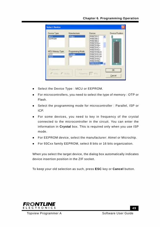
Select the Device Type : MCU or EEPROM.
For microcontrollers, you need to select the type of memory : OTP or
Flash.
Select the programming mode for microcontroller : Parallel, ISP or
ICP.
For some devices, you need to key in frequency of the crystal
connected to the microcontroller in the circuit. You can enter the
information in Crystal box. This is required only when you use ISP
mode.
For EEPROM device, select the manufacturer: Atmel or Microchip.
For 93Cxx family EEPROM, select 8 bits or 16 bits organization.
When you select the target device, the dialog box automatically indicates
device insertion position in the ZIF socket.
To keep your old selection as such, press ESC key or Cancel button.
Chapter 6. Programming Operation
Software User Guide
50
Topview Programmer A
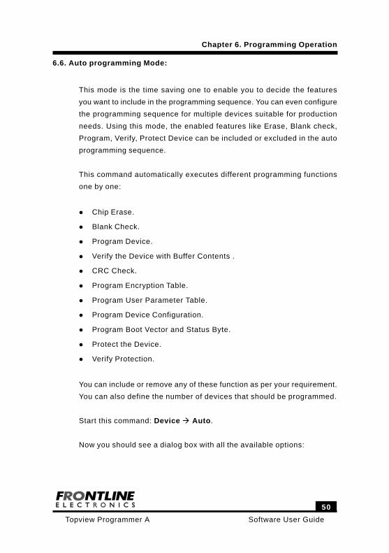
6.6. Auto programming Mode:
This mode is the time saving one to enable you to decide the features
you want to include in the programming sequence. You can even configure
the programming sequence for multiple devices suitable for production
needs. Using this mode, the enabled features like Erase, Blank check,
Program, Verify, Protect Device can be included or excluded in the auto
programming sequence.
This command automatically executes different programming functions
one by one:
Chip Erase.
Blank Check.
Program Device.
Verify the Device with Buffer Contents .
CRC Check.
Program Encryption Table.
Program User Parameter Table.
Program Device Configuration.
Program Boot Vector and Status Byte.
Protect the Device.
Verify Protection.
You can include or remove any of these function as per your requirement.
You can also define the number of devices that should be programmed.
Start this command: Device Auto.
Now you should see a dialog box with all the available options:
Chapter 6. Programming Operation
51
Software User GuideTopview Programmer A
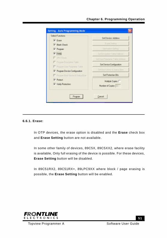
6.6.1. Erase:
In OTP devices, the erase option is disabled and the Erase check box
and Erase Setting button are not available.
In some other family of devices, 89C5X, 89C5XX2, where erase facility
is available, Only full erasing of the device is possible. For these devices,
Erase Setting button will be disabled.
In 89C51RX2, 89C51RX+, 89LPC9XX where block / page erasing is
possible, the Erase Setting button will be enabled.
Chapter 6. Programming Operation
Software User Guide
52
Topview Programmer A
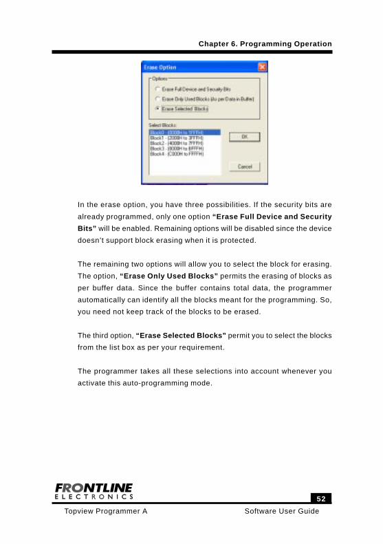
In the erase option, you have three possibilities. If the security bits are
already programmed, only one option “Erase Full Device and Security
Bits” will be enabled. Remaining options will be disabled since the device
doesn’t support block erasing when it is protected.
The remaining two options will allow you to select the block for erasing.
The option, “Erase Only Used Blocks” permits the erasing of blocks as
per buffer data. Since the buffer contains total data, the programmer
automatically can identify all the blocks meant for the programming. So,
you need not keep track of the blocks to be erased.
The third option, “Erase Selected Blocks” permit you to select the blocks
from the list box as per your requirement.
The programmer takes all these selections into account whenever you
activate this auto-programming mode.
Chapter 6. Programming Operation
53
Software User GuideTopview Programmer A
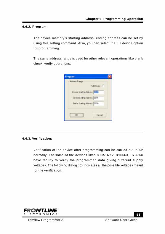
6.6.2. Program:
The device memory’s starting address, ending address can be set by
using this setting command. Also, you can select the full device option
for programming.
The same address range is used for other relevant operations like blank
check, verify operations.
6.6.3. Verification:
Verification of the device after programming can be carried out in 5V
normally. For some of the devices likes 89C51RX2, 89C66X, 87C76X
have facility to verify the programmed data giving different supply
voltages. The following dialog box indicates all the possible voltages meant
for the verification.
Chapter 6. Programming Operation
Software User Guide
54
Topview Programmer A
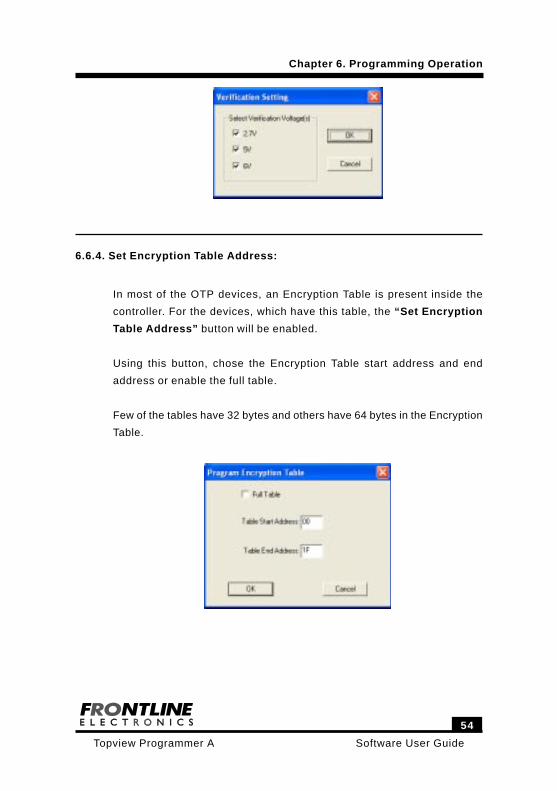
6.6.4. Set Encryption Table Address:
In most of the OTP devices, an Encryption Table is present inside the
controller. For the devices, which have this table, the “Set Encryption
Table Address” button will be enabled.
Using this button, chose the Encryption Table start address and end
address or enable the full table.
Few of the tables have 32 bytes and others have 64 bytes in the Encryption
Table.
Chapter 6. Programming Operation
55
Software User GuideTopview Programmer A
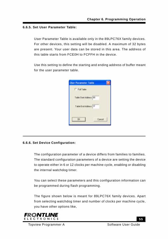
6.6.5. Set User Parameter Table:
User Parameter Table is available only in the 89LPC76X family devices.
For other devices, this setting will be disabled. A maximum of 32 bytes
are present. Your user data can be stored in this area. The address of
this table starts from FCE0H to FCFFH in the device.
Use this setting to define the starting and ending address of buffer meant
for the user parameter table.
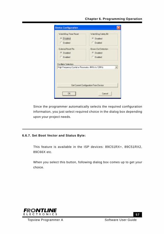
6.6.6. Set Device Configuration:
The configuration parameter of a device differs from families to families.
The standard configuration parameters of a device are setting the device
to operate either in 6 or 12 clocks per machine cycle, enabling or disabling
the internal watchdog timer.
You can select these parameters and this configuration information can
be programmed during flash programming.
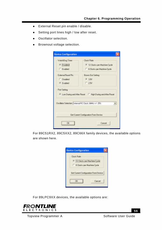
The figure shown below is meant for 89LPC76X family devices. Apart
from selecting watchdog timer and number of clocks per machine cycle,
you have other options like,
Chapter 6. Programming Operation
Software User Guide
56
Topview Programmer A
Chapter 6. Programming Operation
External Reset pin enable / disable.
Setting port lines high / low after reset.
Oscillator selection.
Brownout voltage selection.
For 89C51RX2, 89C5XX2, 89C66X family devices, the available options
are shown here.
For 89LPC9XX devices, the available options are:
57
Software User GuideTopview Programmer A
Since the programmer automatically selects the required configuration
information, you just select required choice in the dialog box depending
upon your project needs.
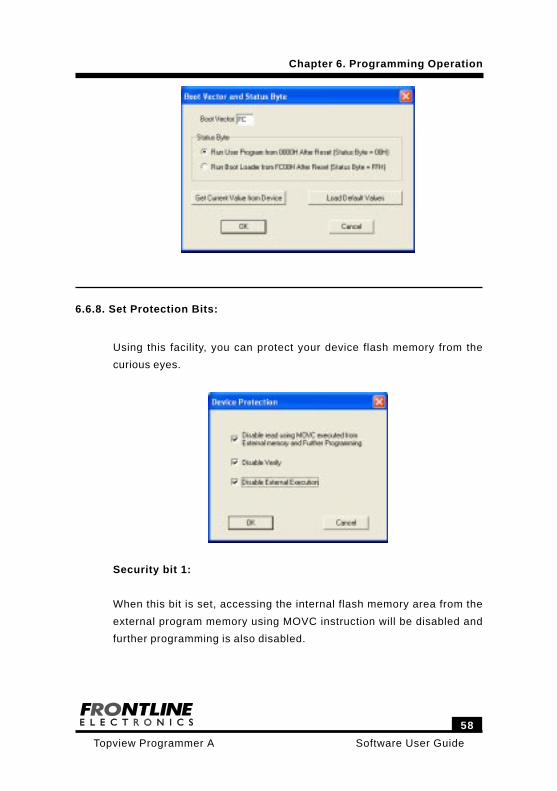
6.6.7. Set Boot Vector and Status Byte:
This feature is available in the ISP devices: 89C51RX+, 89C51RX2,
89C66X etc.
When you select this button, following dialog box comes up to get your
choice.
Chapter 6. Programming Operation
Software User Guide
58
Topview Programmer A
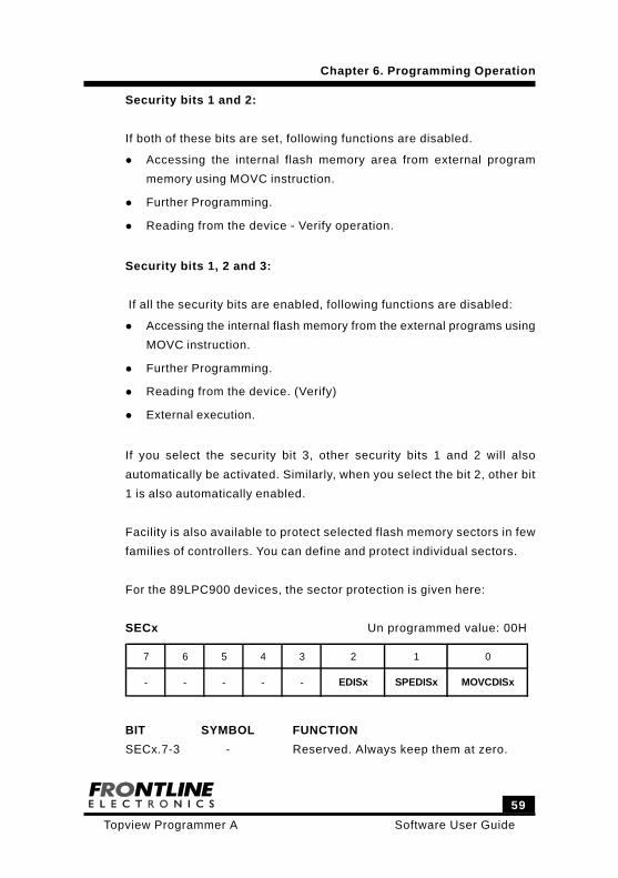
6.6.8. Set Protection Bits:
Using this facility, you can protect your device flash memory from the
curious eyes.
Security bit 1:
When this bit is set, accessing the internal flash memory area from the
external program memory using MOVC instruction will be disabled and
further programming is also disabled.
Chapter 6. Programming Operation
59
Software User GuideTopview Programmer A
Security bits 1 and 2:
If both of these bits are set, following functions are disabled.
Accessing the internal flash memory area from external program
memory using MOVC instruction.
Further Programming.
Reading from the device - Verify operation.
Security bits 1, 2 and 3:
If all the security bits are enabled, following functions are disabled:
Accessing the internal flash memory from the external programs using
MOVC instruction.
Further Programming.
Reading from the device. (Verify)
External execution.
If you select the security bit 3, other security bits 1 and 2 will also
automatically be activated. Similarly, when you select the bit 2, other bit
1 is also automatically enabled.
Facility is also available to protect selected flash memory sectors in few
families of controllers. You can define and protect individual sectors.
For the 89LPC900 devices, the sector protection is given here:
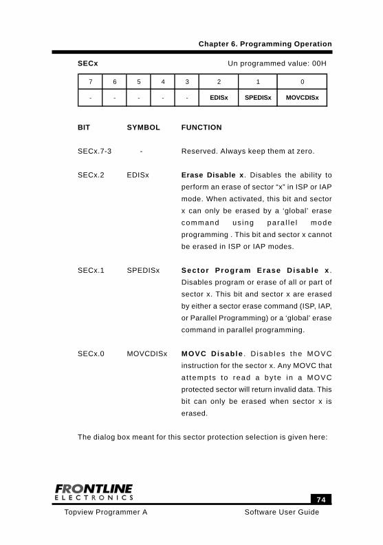
SECx Un programmed value: 00H
7 6 5 4 3 2 1 0
- - - - - EDISx SPEDISx MOVCDISx
BIT SYMBOL FUNCTION
SECx.7-3 - Reserved. Always keep them at zero.
Chapter 6. Programming Operation
Software User Guide
60
Topview Programmer A
SECx.2 EDISx Erase Disable x. Disables the ability to
perform an erase of sector “x” in ISP or IAP
mode. When activated, this bit and sector
x can only be erased by a ‘global’ erase
command us ing para l le l mode
programming . This bit and sector x cannot
be erased in ISP or IAP modes.
SECx.1 SPEDISx Sector Program Erase Disable x .
Disables program or erase of all or part of
sector x. This bit and sector x are erased
by either a sector erase command (ISP, IAP,
or Parallel Programming) or a ‘global’ erase
command in parallel programming.
SECx.0 MOVCDISx MOVC Disable . D isab les the MOVC
instruction for the sector x. Any MOVC that
a t tempts to read a by te in a MOVC
protected sector will return invalid data. This
bit can only be erased when sector x is
erased.
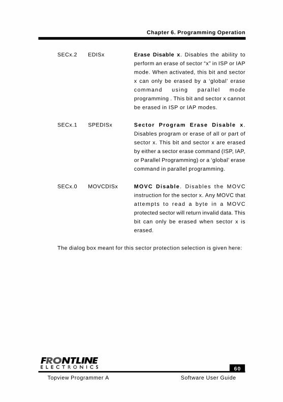
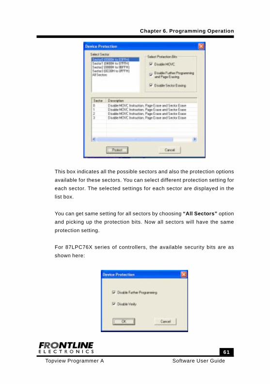
The dialog box meant for this sector protection selection is given here:
Chapter 6. Programming Operation
61
Software User GuideTopview Programmer A
This box indicates all the possible sectors and also the protection options
available for these sectors. You can select different protection setting for
each sector. The selected settings for each sector are displayed in the
list box.
You can get same setting for all sectors by choosing “All Sectors” option
and picking up the protection bits. Now all sectors will have the same
protection setting.
For 87LPC76X series of controllers, the available security bits are as
shown here:
Chapter 6. Programming Operation
Software User Guide
62
Topview Programmer A
Security Bit 1:
If it is set, then no further programming can be done.
Security Bit 1 and 2:
If both the bits are enabled, then further programming and read back
(Verify) facilities are disabled. If you read the protected device, you will
get only FFH from all the locations.
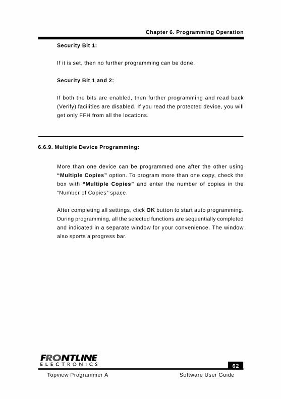
6.6.9. Multiple Device Programming:
More than one device can be programmed one after the other using
“Multiple Copies” option. To program more than one copy, check the
box with “Multiple Copies” and enter the number of copies in the
“Number of Copies” space.
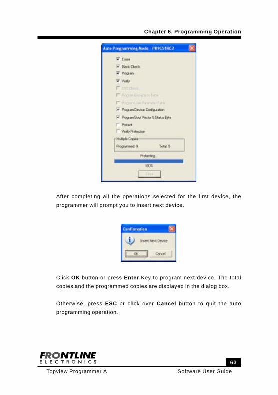
After completing all settings, click OK button to start auto programming.
During programming, all the selected functions are sequentially completed
and indicated in a separate window for your convenience. The window
also sports a progress bar.
Chapter 6. Programming Operation
63
Software User GuideTopview Programmer A
After completing all the operations selected for the first device, the
programmer will prompt you to insert next device.
Click OK button or press Enter Key to program next device. The total
copies and the programmed copies are displayed in the dialog box.
Otherwise, press ESC or click over Cancel button to quit the auto
programming operation.
Chapter 6. Programming Operation
Software User Guide
64
Topview Programmer A
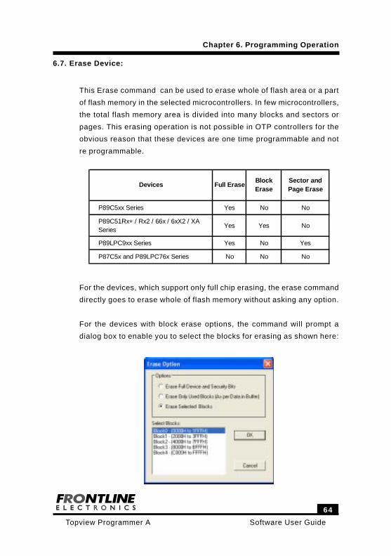
6.7. Erase Device:
This Erase command can be used to erase whole of flash area or a part
of flash memory in the selected microcontrollers. In few microcontrollers,
the total flash memory area is divided into many blocks and sectors or
pages. This erasing operation is not possible in OTP controllers for the
obvious reason that these devices are one time programmable and not
re programmable.
P89C5xx Series Yes No No
P89C51Rx+ / Rx2 / 66x / 6xX2 / XA Series
Yes Yes No
P89LPC9xx Series Yes No Yes
P87C5x and P89LPC76x Series No No No
Devices Full EraseBlock Erase
Sector and Page Erase
For the devices, which support only full chip erasing, the erase command
directly goes to erase whole of flash memory without asking any option.
For the devices with block erase options, the command will prompt a
dialog box to enable you to select the blocks for erasing as shown here:
Chapter 6. Programming Operation
65
Software User GuideTopview Programmer A
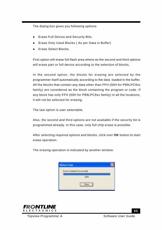
The dialog box gives you following options:
Erase Full Device and Security Bits.
Erase Only Used Blocks ( As per Data in Buffer)
Erase Select Blocks.
First option will erase full flash area where as the second and third options
will erase part or full device according to the selection of blocks.
In the second option, the blocks for erasing are selected by the
programmer itself automatically according to the data loaded in the buffer.
All the blocks that contain any data other than FFH (00H for P89LPC9xx
family) are considered as the block containing the program or code. If
any block has only FFH (00H for P89LPC9xx family) in all the locations,
it will not be selected for erasing.
The last option is user selectable.
Also, the second and third options are not available if the security bit is
programmed already. In this case, only full chip erase is possible.
After selecting required options and blocks, click over OK button to start
erase operation.
The erasing operation is indicated by another window.
Software User Guide
66
Topview Programmer A
Chapter 6. Programming Operation
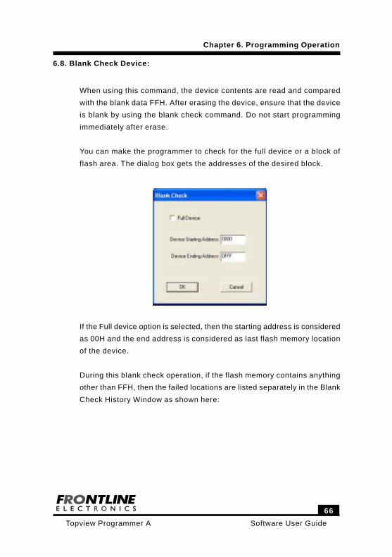
6.8. Blank Check Device:
When using this command, the device contents are read and compared
with the blank data FFH. After erasing the device, ensure that the device
is blank by using the blank check command. Do not start programming
immediately after erase.
You can make the programmer to check for the full device or a block of
flash area. The dialog box gets the addresses of the desired block.
If the Full device option is selected, then the starting address is considered
as 00H and the end address is considered as last flash memory location
of the device.
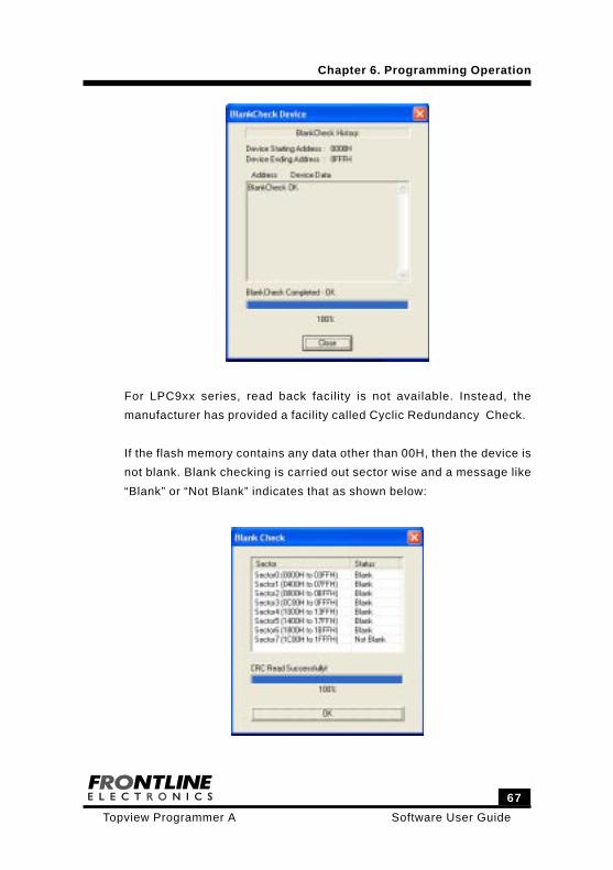
During this blank check operation, if the flash memory contains anything
other than FFH, then the failed locations are listed separately in the Blank
Check History Window as shown here:
67
Software User GuideTopview Programmer A
Chapter 6. Programming Operation
For LPC9xx series, read back facility is not available. Instead, the
manufacturer has provided a facility called Cyclic Redundancy Check.
If the flash memory contains any data other than 00H, then the device is
not blank. Blank checking is carried out sector wise and a message like
“Blank” or “Not Blank” indicates that as shown below:
Software User Guide
68
Topview Programmer A
Chapter 6. Programming Operation
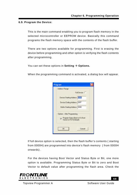
6.9. Program the Device:
This is the main command enabling you to program flash memory in the
selected microcontroller or EEPROM device. Basically this command
programs the flash memory space with the contents of the flash buffer.
There are two options available for programming. First is erasing the
device before programming and other option is verifying the flash contents
after programming.
You can set these options in Setting Options.
When the programming command is activated, a dialog box will appear.
If full device option is selected, then the flash buffer’s contents ( starting
from 0000H) are programmed into device’s flash memory ( from 0000H
onwards) .
For the devices having Boot Vector and Status Byte or Bit, one more
option is available. Programming Status Byte or Bit to zero and Boot
Vector to default value after programming the flash area. Check the
69
Software User GuideTopview Programmer A
Chapter 6. Programming Operation
corresponding check box to program these bytes.
After selection, click over OK button to start programming operation.
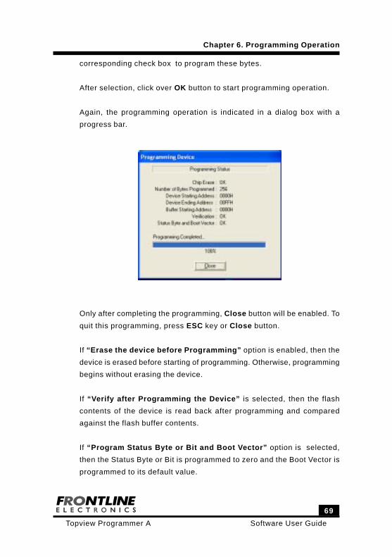
Again, the programming operation is indicated in a dialog box with a
progress bar.
Only after completing the programming, Close button will be enabled. To
quit this programming, press ESC key or Close button.
If “Erase the device before Programming” option is enabled, then the
device is erased before starting of programming. Otherwise, programming
begins without erasing the device.
If “Verify after Programming the Device” is selected, then the flash
contents of the device is read back after programming and compared
against the flash buffer contents.
If “Program Status Byte or Bit and Boot Vector” option is selected,
then the Status Byte or Bit is programmed to zero and the Boot Vector is
programmed to its default value.
Software User Guide
70
Topview Programmer A
Chapter 6. Programming Operation
6.10. Read Device:
Read command can be used to read the flash contents of the selected
device and store them in the flash buffer in the host computer.
After reading from the flash memory of the device, the contents can be
stored either in Intel Hex format or in Binary.
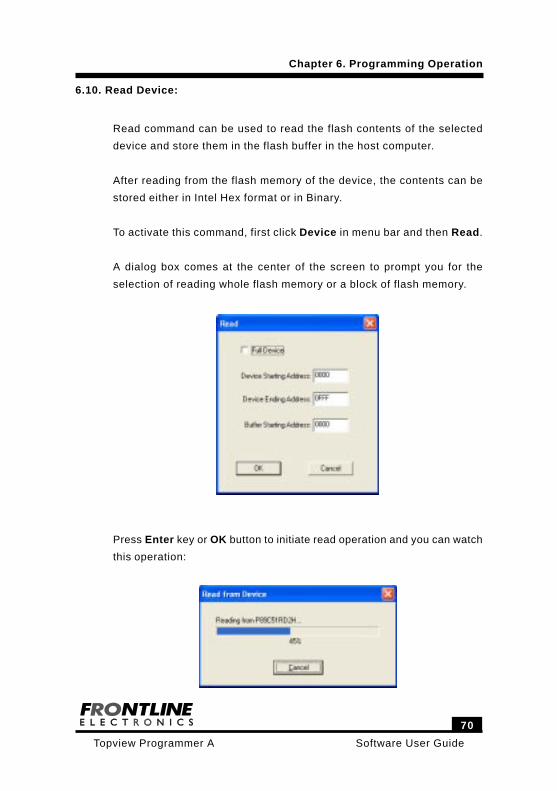
To activate this command, first click Device in menu bar and then Read.
A dialog box comes at the center of the screen to prompt you for the
selection of reading whole flash memory or a block of flash memory.
Press Enter key or OK button to initiate read operation and you can watch
this operation:
71
Software User GuideTopview Programmer A
Chapter 6. Programming Operation
6.11. Verify Device:
Verify command enables you to verify device flash memory contents with
flash buffer for confirmation.
For the most of the devices, the verifying voltage is 5V. Some of the
devices have verifying voltage as 2.7V, 5V and 6V. These verification
voltages can be selected from Verification command from Setting menu.
Select Verify command from Device menu.
You can see a window popping up to prompt you to select either the
complete device for verification or a block of flash memory.
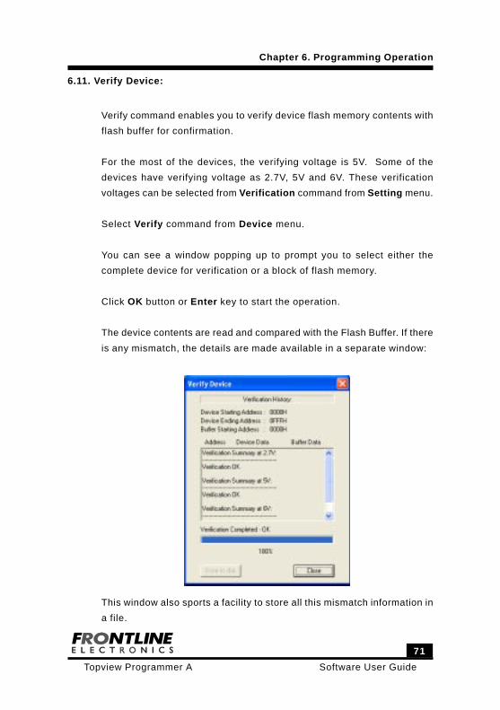
Click OK button or Enter key to start the operation.
The device contents are read and compared with the Flash Buffer. If there
is any mismatch, the details are made available in a separate window:
This window also sports a facility to store all this mismatch information in
a file.
Software User Guide
72
Topview Programmer A
Chapter 6. Programming Operation
6.12. Protect Device:
This protection command helps you to secure the flash memory contents
of the selected device against unauthorized reading.
Some of the microcontrollers are having two levels of program memory
lock and remaining devices have three level program memory security.
Apart from two and three level protection, some devices are having sector
wise three level protection. P89LPC9xx family devices are having that
kind of protection facility. In this family, each sector is having three bits
for protection.
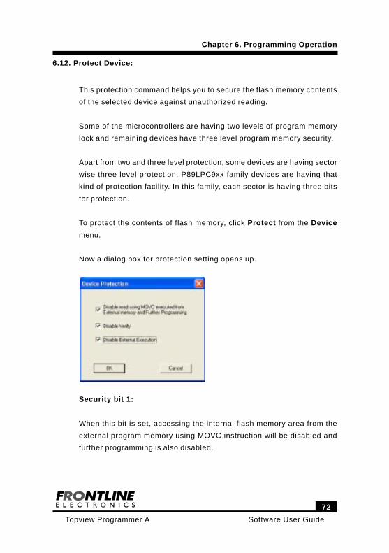
To protect the contents of flash memory, click Protect from the Device
menu.
Now a dialog box for protection setting opens up.
Security bit 1:
When this bit is set, accessing the internal flash memory area from the
external program memory using MOVC instruction will be disabled and
further programming is also disabled.
73
Software User GuideTopview Programmer A
Chapter 6. Programming Operation
Security bits 1 and 2:
If both of these bits are set, following functions are disabled.
Accessing the internal flash memory area from external program
memory using MOVC instruction.
Further Programming.
Reading from the device - Verify operation.
Security bits 1, 2 and 3:
If all the security bits are enabled, following functions are disabled:
Accessing the internal flash memory from the external programs using
MOVC instruction.
Further Programming.
Reading from the device. (Verify)
External execution.
If you select the security bit 3, other security bits 1 and 2 will also
automatically be activated. Similarly, when you select the bit 2, other bit
1 also automatically enabled.
Facility is also available to protect selected flash memory sectors in few
families of controllers. You can define and protect individual sectors.
For the 89LPC900 devices, the sector protection is given here:
Software User Guide
74
Topview Programmer A
Chapter 6. Programming Operation
SECx Un programmed value: 00H
7 6 5 4 3 2 1 0
- - - - - EDISx SPEDISx MOVCDISx
BIT SYMBOL FUNCTION
SECx.7-3 - Reserved. Always keep them at zero.
SECx.2 EDISx Erase Disable x. Disables the ability to
perform an erase of sector “x” in ISP or IAP
mode. When activated, this bit and sector
x can only be erased by a ‘global’ erase
command us ing para l le l mode
programming . This bit and sector x cannot
be erased in ISP or IAP modes.
SECx.1 SPEDISx Sector Program Erase Disable x .
Disables program or erase of all or part of
sector x. This bit and sector x are erased
by either a sector erase command (ISP, IAP,
or Parallel Programming) or a ‘global’ erase
command in parallel programming.
SECx.0 MOVCDISx MOVC Disable . D isab les the MOVC
instruction for the sector x. Any MOVC that
a t tempts to read a by te in a MOVC
protected sector will return invalid data. This
bit can only be erased when sector x is
erased.
The dialog box meant for this sector protection selection is given here:
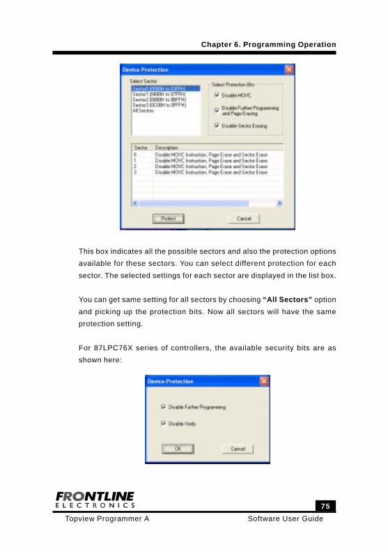
75
Software User GuideTopview Programmer A
Chapter 6. Programming Operation
This box indicates all the possible sectors and also the protection options
available for these sectors. You can select different protection for each
sector. The selected settings for each sector are displayed in the list box.
You can get same setting for all sectors by choosing “All Sectors” option
and picking up the protection bits. Now all sectors will have the same
protection setting.
For 87LPC76X series of controllers, the available security bits are as
shown here:
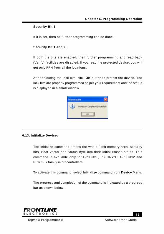
Software User Guide
76
Topview Programmer A
Chapter 6. Programming Operation
Security Bit 1:
If it is set, then no further programming can be done.
Security Bit 1 and 2:
If both the bits are enabled, then further programming and read back
(Verify) facilities are disabled. If you read the protected device, you will
get only FFH from all the locations.
After selecting the lock bits, click OK button to protect the device. The
lock bits are properly programmed as per your requirement and the status
is displayed in a small window.
6.13. Initialize Device:
The initialize command erases the whole flash memory area, security
bits, Boot Vector and Status Byte into their initial erased states. This
command is available only for P89CRx+, P89CRx2H, P89CRx2 and
P89C66x family microcontrollers.
To activate this command, select Initialize command from Device Menu.
The progress and completion of the command is indicated by a progress
bar as shown below:
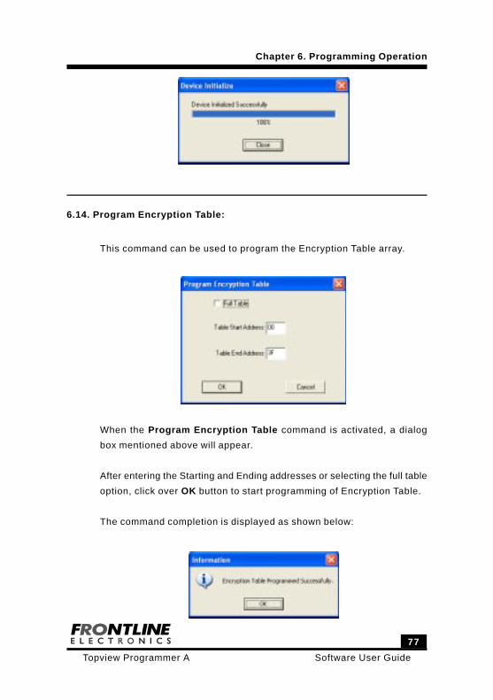
77
Software User GuideTopview Programmer A
Chapter 6. Programming Operation
6.14. Program Encryption Table:
This command can be used to program the Encryption Table array.
When the Program Encryption Table command is activated, a dialog
box mentioned above will appear.
After entering the Starting and Ending addresses or selecting the full table
option, click over OK button to start programming of Encryption Table.
The command completion is displayed as shown below:
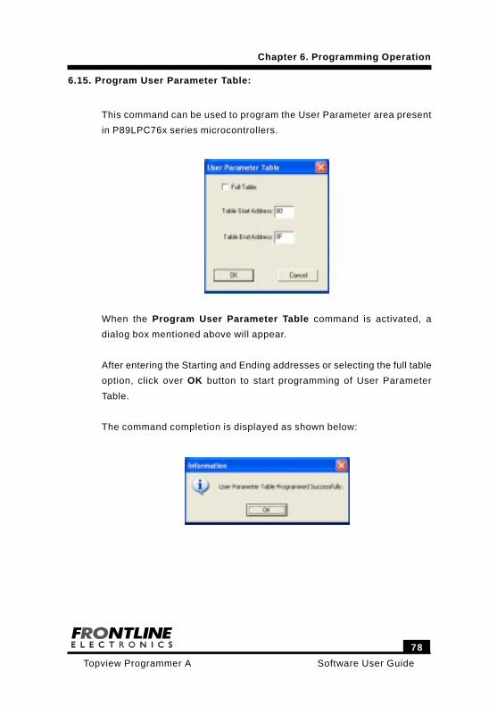
Software User Guide
78
Topview Programmer A
Chapter 6. Programming Operation
6.15. Program User Parameter Table:
This command can be used to program the User Parameter area present
in P89LPC76x series microcontrollers.
When the Program User Parameter Table command is activated, a
dialog box mentioned above will appear.
After entering the Starting and Ending addresses or selecting the full table
option, click over OK button to start programming of User Parameter
Table.
The command completion is displayed as shown below:
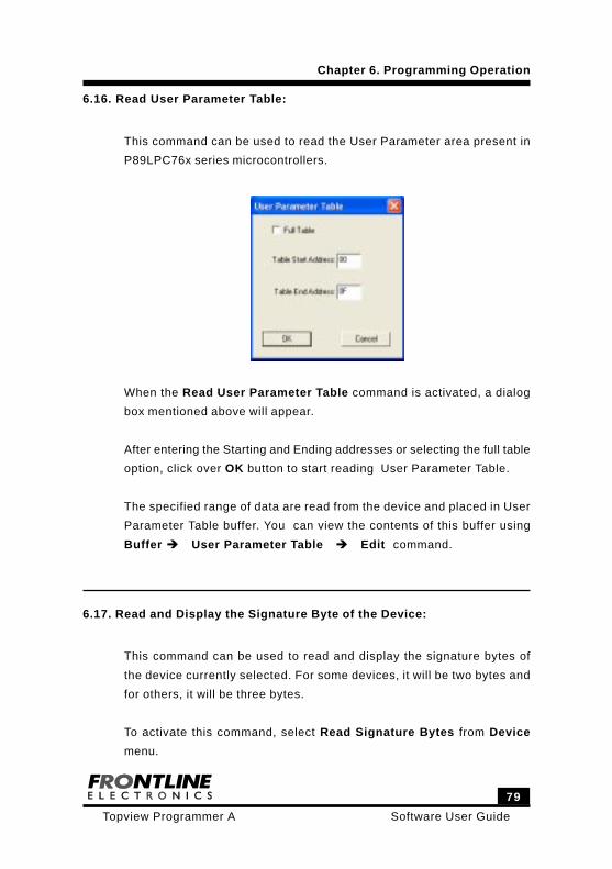
79
Software User GuideTopview Programmer A
Chapter 6. Programming Operation
6.16. Read User Parameter Table:
This command can be used to read the User Parameter area present in
P89LPC76x series microcontrollers.
When the Read User Parameter Table command is activated, a dialog
box mentioned above will appear.
After entering the Starting and Ending addresses or selecting the full table
option, click over OK button to start reading User Parameter Table.
The specified range of data are read from the device and placed in User
Parameter Table buffer. You can view the contents of this buffer using
Buffer User Parameter Table Edit command.
6.17. Read and Display the Signature Byte of the Device:
This command can be used to read and display the signature bytes of
the device currently selected. For some devices, it will be two bytes and
for others, it will be three bytes.
To activate this command, select Read Signature Bytes from Device
menu.
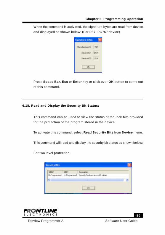
Software User Guide
80
Topview Programmer A
Chapter 6. Programming Operation
When the command is activated, the signature bytes are read from device
and displayed as shown below: (For P87LPC767 device)
Press Space Bar, Esc or Enter key or click over OK button to come out
of this command.
6.18. Read and Display the Security Bit Status:
This command can be used to view the status of the lock bits provided
for the protection of the program stored in the device.
To activate this command, select Read Security Bits from Device menu.
This command will read and display the security bit status as shown below:
For two level protection,
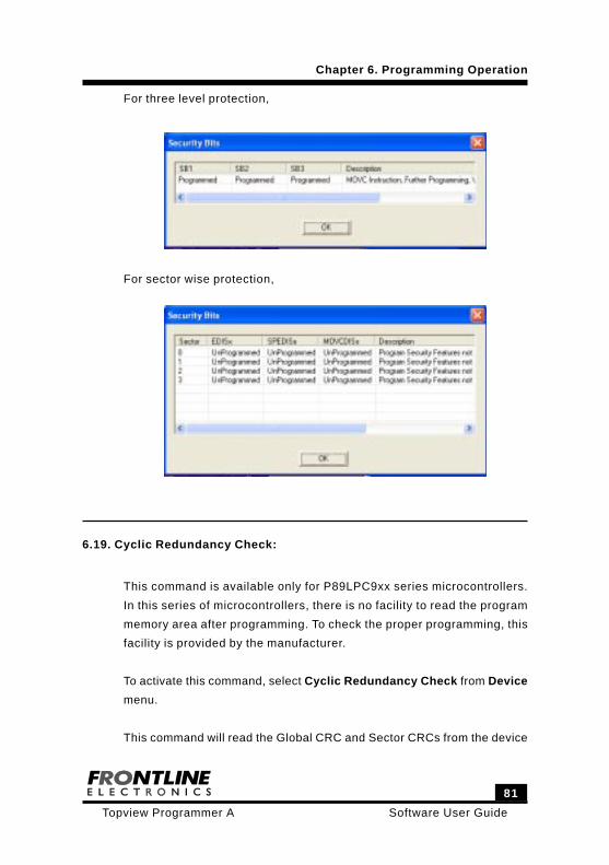
81
Software User GuideTopview Programmer A
Chapter 6. Programming Operation
For three level protection,
For sector wise protection,
6.19. Cyclic Redundancy Check:
This command is available only for P89LPC9xx series microcontrollers.
In this series of microcontrollers, there is no facility to read the program
memory area after programming. To check the proper programming, this
facility is provided by the manufacturer.
To activate this command, select Cyclic Redundancy Check from Device
menu.
This command will read the Global CRC and Sector CRCs from the device
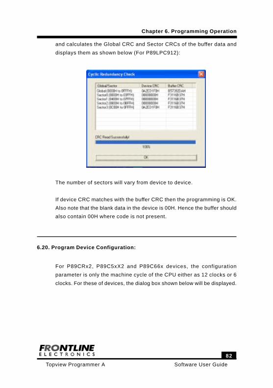
Software User Guide
82
Topview Programmer A
Chapter 6. Programming Operation
and calculates the Global CRC and Sector CRCs of the buffer data and
displays them as shown below (For P89LPC912):
The number of sectors will vary from device to device.
If device CRC matches with the buffer CRC then the programming is OK.
Also note that the blank data in the device is 00H. Hence the buffer should
also contain 00H where code is not present.
6.20. Program Device Configuration:
For P89CRx2, P89C5xX2 and P89C66x devices, the configuration
parameter is only the machine cycle of the CPU either as 12 clocks or 6
clocks. For these of devices, the dialog box shown below will be displayed.
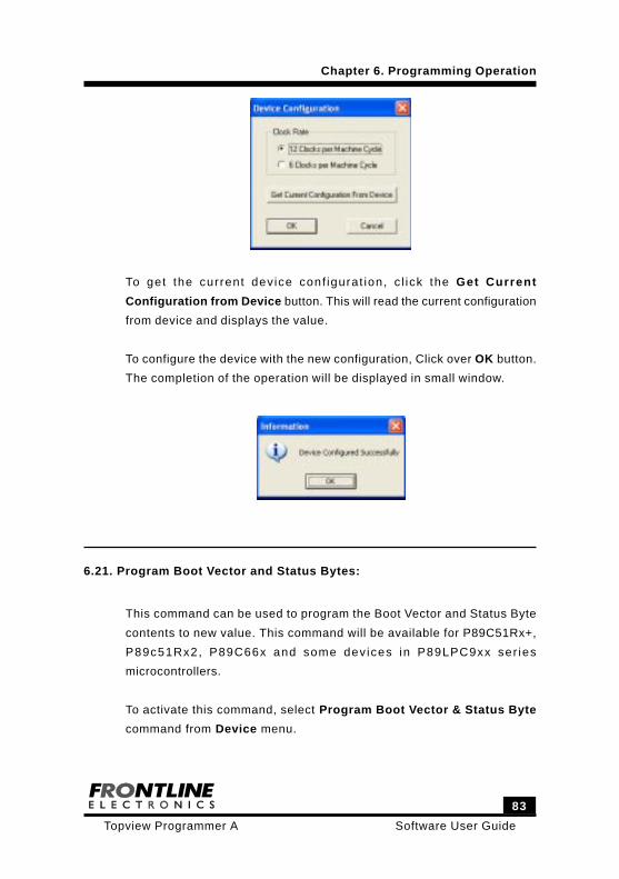
83
Software User GuideTopview Programmer A
Chapter 6. Programming Operation
To get the current device conf igurat ion, c l ick the Get Current
Configuration from Device button. This will read the current configuration
from device and displays the value.
To configure the device with the new configuration, Click over OK button.
The completion of the operation will be displayed in small window.
6.21. Program Boot Vector and Status Bytes:
This command can be used to program the Boot Vector and Status Byte
contents to new value. This command will be available for P89C51Rx+,
P89c51Rx2, P89C66x and some dev ices in P89LPC9xx ser ies
microcontrollers.
To activate this command, select Program Boot Vector & Status Byte
command from Device menu.
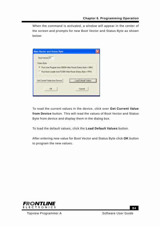
Software User Guide
84
Topview Programmer A
Chapter 6. Programming Operation
When the command is activated, a window will appear in the center of
the screen and prompts for new Boot Vector and Status Byte as shown
below:
To read the current values in the device, click over Get Current Value
from Device button. This will read the values of Boot Vector and Status
Byte from device and display them in the dialog box.
To load the default values, click the Load Default Values button.
After entering new value for Boot Vector and Status Byte click OK button
to program the new values.
85
Software User GuideTopview Programmer A
Chapter 7. Programming the Soldered Device in the Target Hardware
7.1. Introduction:
Many Microcontrollers from Philips have the facility to get programmed
even after soldered in the target board. You need not remove the device
from the PCB for programming purpose. This is very much required when
you use SMD devices in your applications. These controllers have In
System Programming and In Circuit Programming facilities to enable you
to update target application in the field and use the same hardware in
different applications by varying the software. If you provide a simple
connector in your target hardware, you can upgrade/change the target
programming code using Topview Programmer A.
7.2. ICP and ISP Modes:
Philips Semiconductor has made different modes of programming
available in many of the microcontrollers to enable the user get versatile
up-gradation facility in his/her applications.
In System Programming (ISP).
In Circuit Programming (ICP).
In Application Programming (IAP).
Parallel Programming.
These microcontrollers come with all required hardware and software
resources to program flash memory area when the devices are properly
initialized. The device takes care of complicated timing requirements all
by itself along with the programming software kept at the higher location.
ISP mode uses the serial port of the device for programming and you
can program the flash memory area keeping the controller mounted in
the target hardware. The device can be programmed with the application
code without removing the device from the PCB. Also all the programming
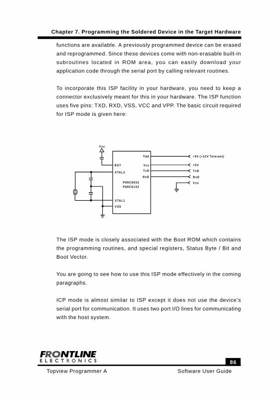
Software User Guide
86
Topview Programmer A
Chapter 7. Programming the Soldered Device in the Target Hardware
functions are available. A previously programmed device can be erased
and reprogrammed. Since these devices come with non-erasable built-in
subroutines located in ROM area, you can easily download your
application code through the serial port by calling relevant routines.
To incorporate this ISP facility in your hardware, you need to keep a
connector exclusively meant for this in your hardware. The ISP function
uses five pins: TXD, RXD, VSS, VCC and VPP. The basic circuit required
for ISP mode is given here:
R S T
X TA L 2
X TA L 1
V SS
V pp
V c c
T x D
R x D
P 8 9 C 6 0 X2P 8 9 C 6 1 X2
V c c
+ 5 V (+ 1 2 V To le ran t)
+ 5 V
T x D
R x D
V s s
The ISP mode is closely associated with the Boot ROM which contains
the programming routines, and special registers, Status Byte / Bit and
Boot Vector.
You are going to see how to use this ISP mode effectively in the coming
paragraphs.
ICP mode is almost similar to ISP except it does not use the device’s
serial port for communication. It uses two port I/O lines for communicating
with the host system.

87
Software User GuideTopview Programmer A
Chapter 7. Programming the Soldered Device in the Target Hardware
The following table gives more clear picture about both ISP and ICP:
ISP ICP
In ISP mode, program m ing is done by
serial port w ith the help of
program ming software kept at the
Boot ROM .
In ICP mo de, a separate hardware
provided in the d evice itself takes
responsibility to progra m the dev ice usin g
two I/O port lines. One line is fo r seria l
c lock and o ther line is for data transfer.
Basic R equirem ents:
• Reset C ircuit.
• Clock Circuit.
• Serial port le ve l shifter for
program ming using PC seria l
port.
Basic R equirem ents:
• Reset C ircuit.
Lines used fo r Da ta Transfer:
• TXD.
• RX D.
• G ND.
Lines used fo r Da ta Transfer:
• P0.4
• P0.5
• G ND.
Associated w ith Specia l Registers ,
Boot V ector and Status B yte/ Bit and
Boot ROM .
No S pecia l Registers and Bo ot RO M.
For som e d evice s, the device cannot
be erased if the device is protected.
Dev ice can b e erased even if the dev ice is
protec ted .
The p ro gram ming com m ands and
data are transferred in Intel Hex
form at.
The p ro gram ming com m ands and data
transferred serially in bytes .
Boot V ector should have the s tarting
address of th e Boot ROM fo r p roper
opera tion of ISP m ode
No such B oot Vector.
In P 89L PC9X X devices, the IS P
m onito r is placed in the last 1K B yte
space. W hen you erase full dev ice,
th is ISP monitor also gets erased. For
proper ISP mode operation, you need
to p rogram last 1K B yte with prope r
m onito r to start ISP again.
In ICP, no such mon itor is available .

Software User Guide
88
Topview Programmer A
Chapter 7. Programming the Soldered Device in the Target Hardware
IAP mode is for embedding the on chip programming facility in your tar-
get application. You may include this in your application to provide a kind
of self-upgradation facility or to get latest calibration information and etc.
You need to refer the Philips Documentation to know more on this IAP
mode and such a discussion is beyond the scope of this manual.
Topview Device Programmer A has required facility to program these
microcontrollers in Parallel Mode. You may use this Parallel Programming
facility to restore the Boot ROM in the device after it is erased.
7.3. Power on Reset Code Execution:
The controllers (with ISP facility) contain a Special flash Register, Status
Byte which indicates the starting address of the program code. At the
falling edge of reset, the controller examines the Status Byte and if the
Status Byte is set to zero, power up execution starts at location 0000H,
which is the normal start address of user application code. When the
Status Byte is set to a value other than zero, the factory masked ROM
ISP Boot loader is invoked. The factory default for the Status Byte is
FFH. Once set to 00H, the Status Byte only be changed back to FFH by
a full chip erasing when using ISP.
7.4. Hardware Activate of the Boot Loader:
The microcontroller ’s Boot Loader can also be executed by holding PSEN
low, EA grater than VIH (such as +5V) and ALE high (or not connected)
at the falling edge of Reset. This is same effect as having a nonzero
Status Byte. This allows an application to be built that will normally
execute the end user ’s code but can be manually forced into ISP
operation.
89
Software User GuideTopview Programmer A
Chapter 7. Programming the Soldered Device in the Target Hardware
After programming the flash, the Status Byte should be programmed to
zero in order to allow execution of the user application code beginning at
0000H.
7.5. Boot ROM:
When the microcontroller program its flash memory during ISP, all of the
low-level details are handled by the code contained in 1K Byte Boot ROM.
The size of the Boot ROM varies from device to device. Boot ROM
operations include: Erase Block, Program Byte, Verify Byte, Program
Security Bit etc. The Boot ROM area is mostly located at the address
FC00H- FFFFH in a non erasable masked ROM.
7.6. Status Byte/Bit:
The Status Byte is located in the programmable flash memory. After
Reset, the microcontroller checks the Status Byte.
If the Status Byte is 0, the program begins executing from address 0000H.
If the Status Byte is not 0 (FFH is preferred), the program jumps to the
address pointed to by the Boot Vector. The pointed address is the
beginning of the ISP code.
After programming the flash memory, the Status Byte should be erased
to 00H in order to allow the execution user ’s code beginning at address
0000H.
Some devices may have the Status Byte and some may sport Status Bit.
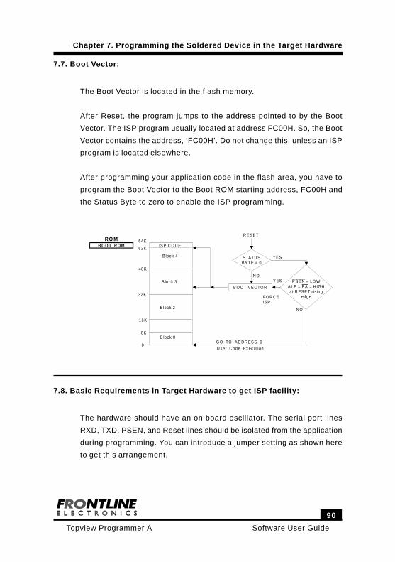
Software User Guide
90
Topview Programmer A
Chapter 7. Programming the Soldered Device in the Target Hardware
7.7. Boot Vector:
The Boot Vector is located in the flash memory.
After Reset, the program jumps to the address pointed to by the Boot
Vector. The ISP program usually located at address FC00H. So, the Boot
Vector contains the address, ‘FC00H’. Do not change this, unless an ISP
program is located elsewhere.
After programming your application code in the flash area, you have to
program the Boot Vector to the Boot ROM starting address, FC00H and
the Status Byte to zero to enable the ISP programming.
RO MB O O T R O M IS P C O D E
64 K
62 K
B loc k 4
48 K
32 K
B loc k 3
B loc k 2
16 K
8K
0
B loc k 0G O TO A D D R ES S 0U s er C od e Ex ec ution
B O O T V E C TOR
R E SE T
Y ESS TATU SB YT E = 0
P SE NE A
= LO WA L E = = H IGHat R ES E T r ising
ed ge
Y ES
FO R C EIS P
N O
N O
7.8. Basic Requirements in Target Hardware to get ISP facility:
The hardware should have an on board oscillator. The serial port lines
RXD, TXD, PSEN, and Reset lines should be isolated from the application
during programming. You can introduce a jumper setting as shown here
to get this arrangement.
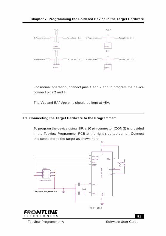
91
Software User GuideTopview Programmer A
Chapter 7. Programming the Soldered Device in the Target Hardware
123
123
123
123
To A p p lic a t io n C irc u itTo P rog ra m m e r
R X D
To A p p lic a t io n C irc u itTo P rog ra m m e r
T X D
To A p p lic a t io n C irc u itTo P rog ra m m e r
P S E N
To A p p lic a t io n C irc u itTo P rog ra m m e r
R S T
For normal operation, connect pins 1 and 2 and to program the device
connect pins 2 and 3.
The Vcc and EA/ Vpp pins should be kept at +5V.
7.9. Connecting the Target Hardware to the Programmer:
To program the device using ISP, a 10 pin connector (CON 3) is provided
in the Topview Programmer PCB at the right side top corner. Connect
this connector to the target as shown here:+5V
Topvie w P rogra m m e r A
Ta rge t Boa rd
C ON 3
IC P/ISP C onnec tor
1 23 45 67 89 10 P
89C
51R
x2/6
6xV
CC
40G
ND
20
XTAL119
XTAL218
P3.0/R XD10
P3.1/TXD11
R ST9
P2.627
P2.728
EA/VPP31
PSEN29
10K 10K
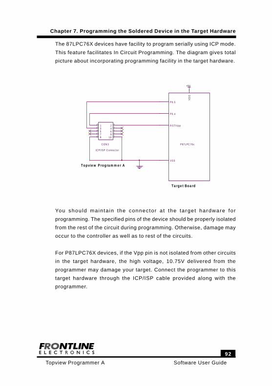
Software User Guide
92
Topview Programmer A
Chapter 7. Programming the Soldered Device in the Target Hardware
The 87LPC76X devices have facility to program serially using ICP mode.
This feature facilitates In Circuit Programming. The diagram gives total
picture about incorporating programming facility in the target hardware.
+5V
Topvie w P rogra m m e r A
Ta rge t Boa rd
C O N 3
IC P / IS P C onnec to r
1 23 45 67 89 10
P87LPC 76x
VD
D
VS S
P0.4
P0.5
R S T/ Vpp
You should mainta in the connector a t the target hardware for
programming. The specified pins of the device should be properly isolated
from the rest of the circuit during programming. Otherwise, damage may
occur to the controller as well as to rest of the circuits.
For P87LPC76X devices, if the Vpp pin is not isolated from other circuits
in the target hardware, the high voltage, 10.75V delivered from the
programmer may damage your target. Connect the programmer to this
target hardware through the ICP/ISP cable provided along with the
programmer.