Embed Size (px)
Citation preview
International Journal of Management, IT & Engineering Vol. 9 Issue 6, June 2019,
ISSN: 2249-0558 Impact Factor: 7.119
Journal Homepage: http://www.ijmra.us, Email: [email protected]
Double-Blind Peer Reviewed Refereed Open Access International Journal - Included in the International Serial
Directories Indexed & Listed at: Ulrich's Periodicals Directory ©, U.S.A., Open J-Gage as well as in Cabell’s
Directories of Publishing Opportunities, U.S.A
39 International journal of Management, IT and Engineering
http://www.ijmra.us, Email: [email protected]
Torque and Drag Analysis in ERD Wells
Tomar, Mayank1
Verma, Arpit2
Jaiswal, Ankur2
ABSTRACT
Highly deviated wells may be described as those well whose inclination exceeds 60° for most of
their length. Extended reach wells are those having MD/TVD ratio ≥ 2. It is possible to extend
directional drilling techniques to increase the inclination to 60° to 90° although certain
alterations may have to be made to drilling practices. Certain modifications to standard rig
equipment may also be necessary to successfully drill these high angled wells. ERD wells drilled
in specific fields and with specific rigs, equipment, personnel, project teams, etc. do not
necessarily imply what may be readily achieved in other areas. Because of the myriad of
variables which control drilling mechanics and performance, local ERD definitions should be
developed in terms of the extent of experience within specific fields and with specific rigs. As one
example aspect, the feasibility of ERD wells is inherently tied to the ability to manage wellbore
stability. This topic alone is impacted by local geology, in-situ formation stresses, possible
tectonic influences, shale reactivity, proposed well inclinations and azimuthal orientations, etc.
The primary means of managing wellbore stability via mud weight, mud chemistry, casing
points, etc. are likewise impacted by considerations such as loss circulation zones, permeable
zones which may cause differential sticking, environmental constraints affecting mud selection
1 Student, M.Tech, Petroleum Engineering Department, Uttaranchal Institute of
Technology, Uttaranchal University, Dehradun, India |
2 Lecturer, Petroleum Engineering Department, Uttaranchal Institute of Technology,
Uttaranchal University, Dehradun, India |
ISSN: 2249-0558Impact Factor: 7.119
40 International journal of Management, IT and Engineering
http://www.ijmra.us, Email: [email protected]
and cuttings disposal, and regulatory requirements and production objectives which constrain
hole/casing programs.
ERD APPLICATIONS
ERD has primarily been used to access reserves from existing offshore platforms
The development of offshore reserves from onshore facilities.
Better optimization of development schemes through the minimization of offshore
facilities and the optimization of their location
To have a link between ERD and horizontal drilling. Horizontal wells are now
commonplace and can offer advantages in terms of enhanced rates, increased reserve access,
increased fracture exposure, lower sand face drawdown, reduced water/gas coning, etc.
In a directional well, the friction between the drillstring and the walls of the well produces drag
and torque. Drag is produced when the drillstring is moving and torque is produced when the
drillstring is rotating. Knowledge of torque and drag will enable the selection of an optimum
well profile and optimum size and weight of the drillstring and its components. In horizontal
wells, it is usual to run the heavy-walled Drillpipe (HWDP) along the curved section of the
wellbore to counteract the forces caused by bending and drag.
The following predictions must be made when designing a horizontal well:
Torque and drag while drilling with surface rotation
Torque and drag while steering a downhole motor
Drag forces while tripping
Buckling forces on the drillstring
The magnitude of the torque and drag is determined by the magnitude with which the pipe
contacts the hole wall and the friction coefficient between the wall and pipe. Unfortunately,
friction is always present and will contribute to the force required to move the object. The
friction force is equal to the normal force times the friction coefficient.
Keywords: ERD Wells, Torque and Drag, Horizontal Wells, Friction, HWDP
ISSN: 2249-0558Impact Factor: 7.119
41 International journal of Management, IT and Engineering
http://www.ijmra.us, Email: [email protected]
INTRODUCTION
One of the most significant problems in extended reach well is torque and drag which is caused
by the friction between the drill string and the wall of the drill hole. It is the critical parameter in
ERD operations for properly sizing the rotary and hoisting equipment of the rig, selecting
optimum well profile and also in the prediction of drill string design.
The magnitude of torque and drag is determined by the magnitude with which the pipe contacts
the hole wall and the friction factor between the pipe and the wall. Friction factor governs the
nature and amount of friction forces acting opposite to the pipe surface. Its values are
independent of the well inclination and depend on hole tortuosity and lubricity of drilling mud.
Torque and drag posed limitations and complexity in drilling extended reach wells due to their
long lateral profile which converts the drill string tension weight into the side weight hence
increase the contact surface of pipe with hole walls. Buckling is also one of the major concern in
extended reach wells as its occurrence increase the torque and drag to very high level. It occurs
when the compressive force in the string becomes greater than the gravity weight of the drill
string. Some additional measures used at present times by the drilling companies to reduce the
friction factor are lubricant addition, changing mud lubricity and use of spiral drill collars &
heavy weight drill pipes.
A proper modelling helps to select the best of the available trajectory profile, best of the
available drill string design for the selected trajectory and drill the well within the desired
economic limits.
OBJECTIVES:
1. To monitor the effects of T&D in the extended reach wells.
2. Identify the problems that affect the magnitude of torque and drag like buckling, lock up,
dog legs and high friction co efficient.
3. The limitations posed to keep T&D within limits of rig equipments. Some of these are
maximum available WOB, maximum available drilling torque, maximum allowable hook load
and maximum tensile yield strength of the drill string components.
ISSN: 2249-0558Impact Factor: 7.119
42 International journal of Management, IT and Engineering
http://www.ijmra.us, Email: [email protected]
4. Some solutions that can be used in reducing T&D, reducing friction co efficient and
maintaining well bore quality.
5. Buckling behavior of drill string is monitored at various depths resulting high T&D.
6. To quantify the equations involved in T&D and used those to solve for the available case
of an extended reach horizontal well.
7. To select the BHA that maintains the hole quality and minimize well bore tortuosity.
CASE STUDY ANALYSIS
Our case includes the Maersk Oil Qatar (MOQ)’s world record BD-04A well drilled in may 2008
in offshore Qatar. This was the successful result of engineering efforts to increase extended reach
capabilities. MOQ started to develop the Al shaheen field offshore Qatar in 1994 with the
application of horizontal drilling techniques in the North Sea. At that time 10,220 feet was the
longest horizontal length drilled by MOQ. In May 2008 the BD-04A well was completed with a
record horizontal length of 35,439 feet. This well set a new world records for both the longest
well at 40,320 feet MDRT and the longest along hole departure of 37,956 feet. The introduction
of new techniques has allowed existing constraints to be successfully challenged and overcome.
This was achieved through the application of sound engineering principles and continuous
optimization during the field development phases.
Our case study will review challenges and planning, leading through to successful drilling of the
BD-04A well. The study will outline the achievements, improved practices and the engineering
analysis of the field data where key learning points have been shared for future use and
applications. It will show that even when constrained by certain limitations such as rig capacity,
major step changes can be achieved by optimizing basic operating parameters.
KEY CHANGES MADE TO REACH TARGET DEPTH
Torque and drag is the major challenge posed through while drilling BD-04 A well and taking all
these factors of torque and drag into consideration subsequent changes were made from time to
time to make reach the target depth of 40,320 ft MDRT. The major target depth deciding factor
here was the maximum torque allowable by the top drive that is capable of providing 40 k ft-lb
ISSN: 2249-0558Impact Factor: 7.119
43 International journal of Management, IT and Engineering
http://www.ijmra.us, Email: [email protected]
of torque @120 RPM. At this depth whole available torque is consumed and if drilling was
continued ahead of the target depth the torque limit exceeds that of top drive capabilities.
Also to meet the challenges of Torque and Drag below the target depth several changes were
made from time to time. These include:
Drill Pipe upgrades to high torque connections to maximize the torque capability of the
top drive.
A tapered drill string with 4” x 5” d/p assembly is used with slim OD in lower part that
significantly reduced torque and friction factor.
Lubricants were added at certain depths to increase torque and reduce friction factor.
Special attention was given on ECD management to maintain borehole stability and
reduce induced well bore losses. This is done through hole enlargement with mud system,
tapered drill string with a section of slim OD drill pipes, and thin mud rheology.
Emphasis was also given to maintain the quality well path with in maximum permissible
dogleg value to reduce the severe dogleg effects.
The use of RSS in the continuous build top hole sections resulting in a smooth catenary
well bore curve which facilitated in pushing the ERD limits.
DATA AVIALABLE
Well Data:
Well Parameters:
Total Hole Length = 40,320 ft (MDRT) with 3,605 ft (TVD), Hole size = 8.5 inch, Casing shoe =
4871 ft (MDRT), Shoe size = 9.625 inch, Horizontal length = 35,439 ft, Inclination angle =
860(at 4,550 ft), Azimuth at 28,850 ft = 99.2deg, Azimuth at 40,320 ft = 134.2deg, Mud weight
used = 9.5 ppg
Drill String Data:
When the drilling is started after 23,630 ft MDRT
Length Components Grade of Pipe
To surface 5” #19.5 ppf GHT50 G105
17,750 ft 5” #19.5 ppf GNC50 G105
6,956 ft 4” #14 ppf GXT39 G105
482 ft 5” #19.5 ppf GNC50 G105
ISSN: 2249-0558Impact Factor: 7.119
44 International journal of Management, IT and Engineering
http://www.ijmra.us, Email: [email protected]
9 ft 5” #50 ppf HWDP – GP
120 ft 6.75” D/C #105.3 ppf
WOBupto 23,630 ft with 5” d/p = 15,000 lb
When the drilling depth is below 23,630 ft MDRT
Length Components Grade of Pipe
To surface 5” #19.5 ppf GHT50 G105
25,188 ft 5” #19.5 ppf GNC50 G105
9 ft 5” #50 ppf HWDP – GP
120 ft 6.75” D/C #105.3 ppf
OD & ID of Tool Joints:
Component OD(in.) ID(in.)
D/c 6.75 2.5
HWDP 5 2.5
4” D/P 4.875 2.8125
5” D/P 6.625 3.5
Tensile Yield Strength of drill pipes:
HT 50 = 9, 39,100 lb, NC 50 = 11, 09,900 lb, XT 39 = 603,000 lb
DATA INTERPRETED:
Well Trajectory data: Double build curve design
Input parameters assumed,
BUR1 = 2.72 0/100 ft, BUR2 = 2.42
0/100 ft, Slant angle = 36deg, Slant length = 350 ft, TVDRT
of EOB2 = 3,482 ft, Length of horizontal section = 35,439 ft, Inclination (EOB2) = 89.80
Output parameter derived through double build curve analysis,
KOP1 = 985 ft
EOB1 (TVD)= 2223 ft Radius of build = 2107 ft MDRT = 2308 ft
Departure = 402 ft
KOP2 (TVD)= 2506 ft MDRT = 2658 ft Departure = 608 ft
EOB2 (TVD) = 3482 ft Radius of build = 2368 ft MDRT = 4881 ft Departure
= 2515 ft
ISSN: 2249-0558Impact Factor: 7.119
45 International journal of Management, IT and Engineering
http://www.ijmra.us, Email: [email protected]
Target(TVD) = 3605 ft Departure = 37,954 ft MDRT = 40,320 ft
KOP1 EOB1 (TVD) KOP2 (TVD) EOB2 (TVD) Target (TVD)
Azimuth 0 51.20 51.2
0 99.2
0 134.2
0
North 0 351 ft 480 ft 953 ft -8,387 ft
South 0 168 ft 328 ft 2,119 ft 35,578 ft
OBJECTIVE OF THE CASE STUDY
Our objective of study is:
1. To identify the Torque, Drag and Buckling forces that acts on the drill string at each
depth up to target depth.
2. Each force are calculated for four cases of Pick up, Slack off, Off bottom and drilling on
bottom.
3. Hook load is calculated for all four at each depth.
4. Critical Buckling load analysis tells whether the string buckles or not with the required
WOB.
5. The whole analysis is done for numerous values of friction factors and the variation in
parameters with depth.
6. To extend the analysis for the complete well results are plotted on graph from top to
bottom target depth.
7. Also the comparison is made with using 5” D/p instead of tapered drill string for each
case and results are plotted.
RESULTS
The result derived from our case study analysis is as follows:
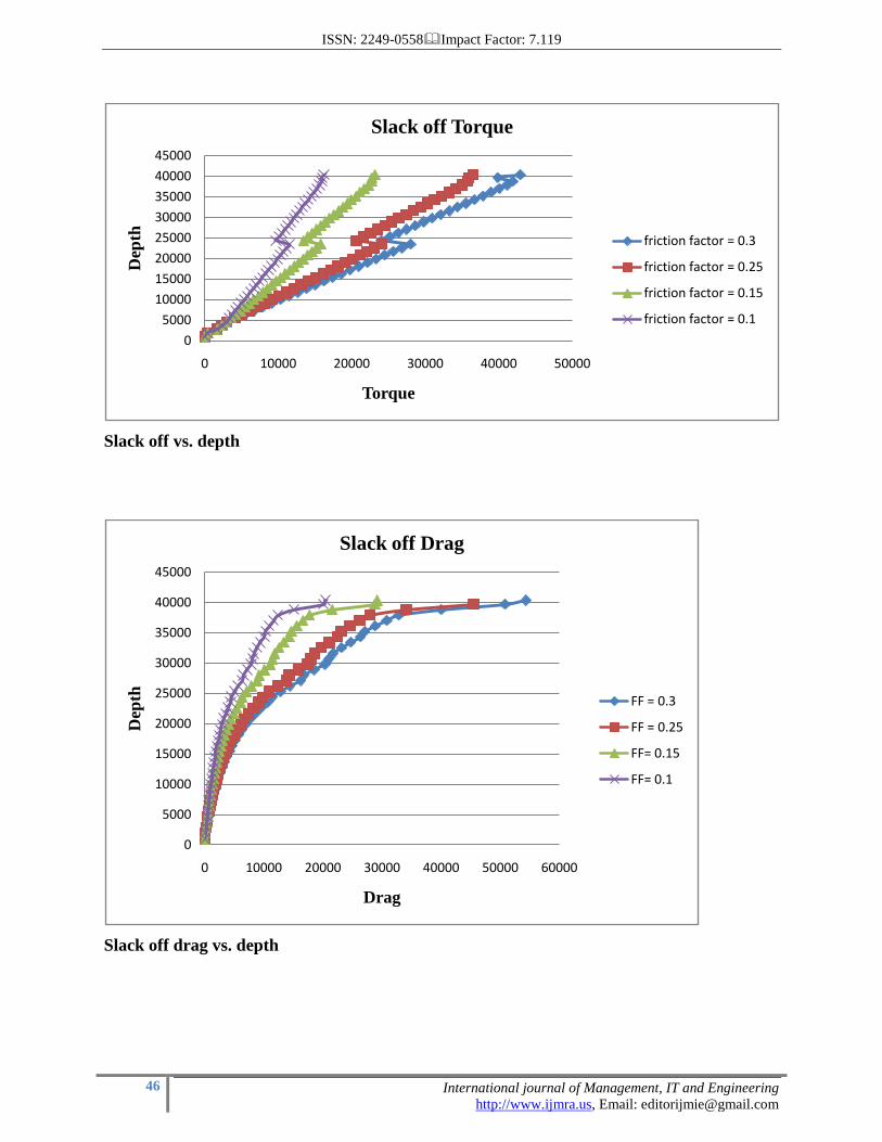
SLACK OFF LOAD VARIATIONS WITH DEPTH
In slack off with rotation the effect of torque is high than drag values:
ISSN: 2249-0558Impact Factor: 7.119
46 International journal of Management, IT and Engineering
http://www.ijmra.us, Email: [email protected]
Slack off vs. depth
Slack off drag vs. depth
0
5000
10000
15000
20000
25000
30000
35000
40000
45000
0 10000 20000 30000 40000 50000
Dep
th
Torque
Slack off Torque
friction factor = 0.3
friction factor = 0.25
friction factor = 0.15
friction factor = 0.1
0
5000
10000
15000
20000
25000
30000
35000
40000
45000
0 10000 20000 30000 40000 50000 60000
Dep
th
Drag
Slack off Drag
FF = 0.3
FF = 0.25
FF= 0.15
FF= 0.1
ISSN: 2249-0558Impact Factor: 7.119
47 International journal of Management, IT and Engineering
http://www.ijmra.us, Email: [email protected]
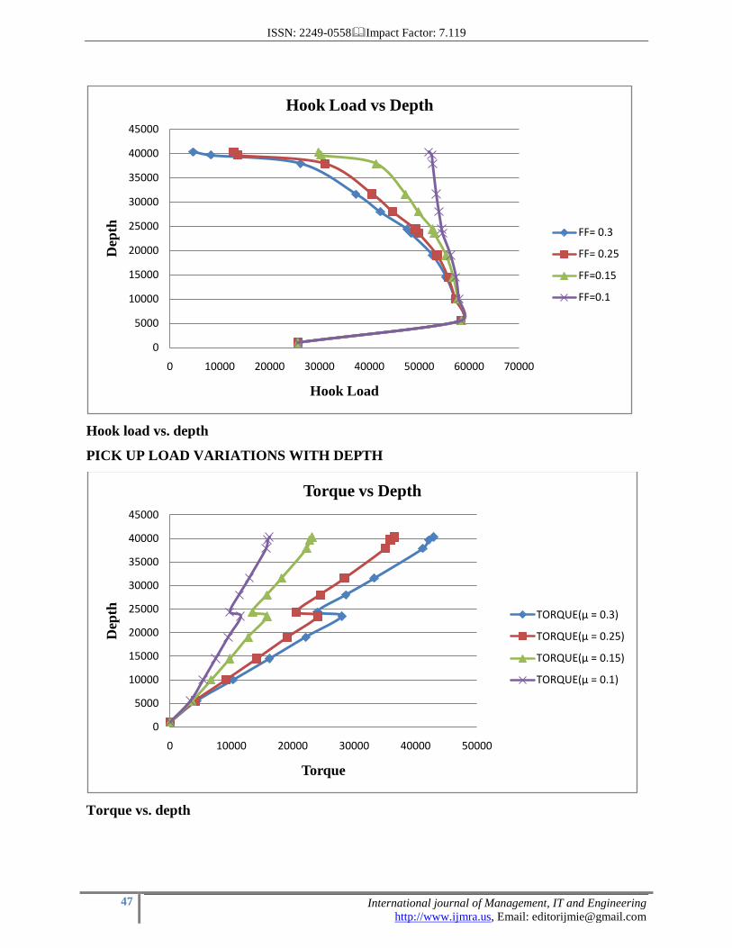
Hook load vs. depth
PICK UP LOAD VARIATIONS WITH DEPTH
Torque vs. depth
0
5000
10000
15000
20000
25000
30000
35000
40000
45000
0 10000 20000 30000 40000 50000 60000 70000
Dep
th
Hook Load
Hook Load vs Depth
FF= 0.3
FF= 0.25
FF=0.15
FF=0.1
0
5000
10000
15000
20000
25000
30000
35000
40000
45000
0 10000 20000 30000 40000 50000
Dep
th
Torque
Torque vs Depth
TORQUE(µ = 0.3)
TORQUE(µ = 0.25)
TORQUE(µ = 0.15)
TORQUE(µ = 0.1)
ISSN: 2249-0558Impact Factor: 7.119
48 International journal of Management, IT and Engineering
http://www.ijmra.us, Email: [email protected]
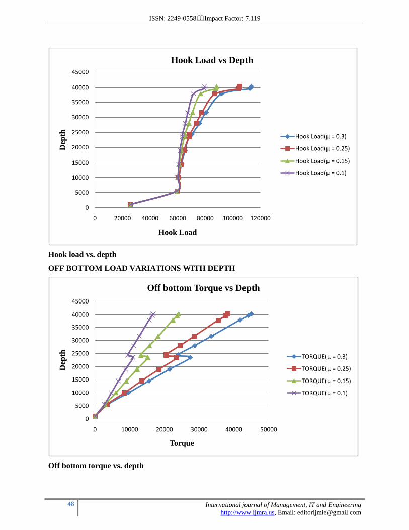
Hook load vs. depth
OFF BOTTOM LOAD VARIATIONS WITH DEPTH
Off bottom torque vs. depth
0
5000
10000
15000
20000
25000
30000
35000
40000
45000
0 20000 40000 60000 80000 100000 120000
Dep
th
Hook Load
Hook Load vs Depth
Hook Load(µ = 0.3)
Hook Load(µ = 0.25)
Hook Load(µ = 0.15)
Hook Load(µ = 0.1)
0
5000
10000
15000
20000
25000
30000
35000
40000
45000
0 10000 20000 30000 40000 50000
Dep
th
Torque
Off bottom Torque vs Depth
TORQUE(µ = 0.3)
TORQUE(µ = 0.25)
TORQUE(µ = 0.15)
TORQUE(µ = 0.1)
ISSN: 2249-0558Impact Factor: 7.119
49 International journal of Management, IT and Engineering
http://www.ijmra.us, Email: [email protected]
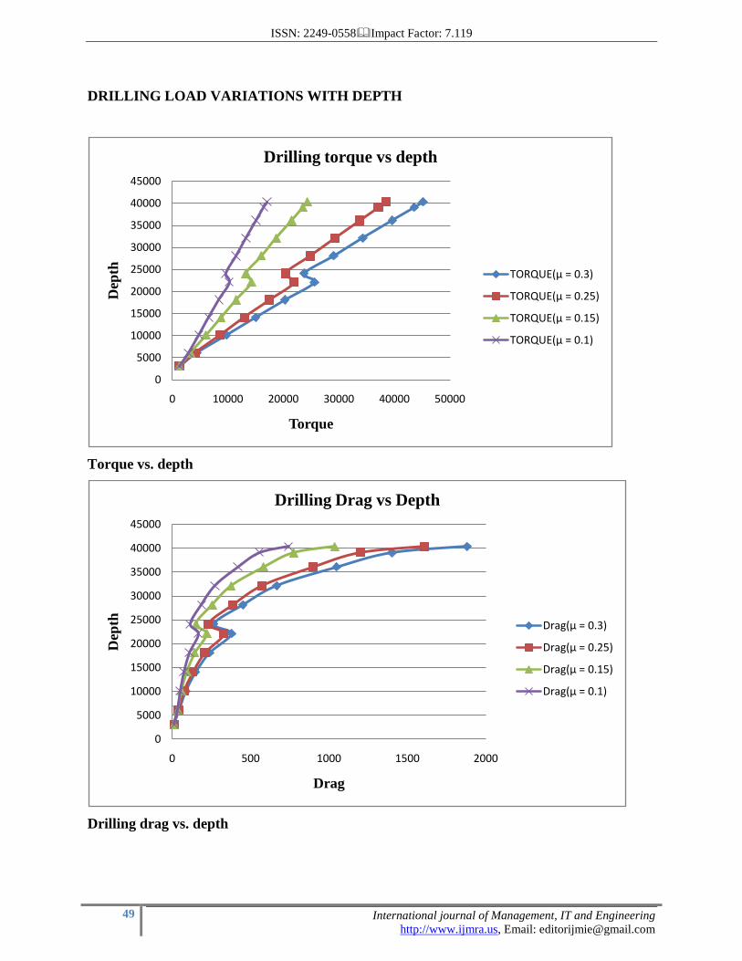
DRILLING LOAD VARIATIONS WITH DEPTH
Torque vs. depth
Drilling drag vs. depth
0
5000
10000
15000
20000
25000
30000
35000
40000
45000
0 10000 20000 30000 40000 50000
Dep
th
Torque
Drilling torque vs depth
TORQUE(µ = 0.3)
TORQUE(µ = 0.25)
TORQUE(µ = 0.15)
TORQUE(µ = 0.1)
0
5000
10000
15000
20000
25000
30000
35000
40000
45000
0 500 1000 1500 2000
Dep
th
Drag
Drilling Drag vs Depth
Drag(µ = 0.3)
Drag(µ = 0.25)
Drag(µ = 0.15)
Drag(µ = 0.1)
ISSN: 2249-0558Impact Factor: 7.119
50 International journal of Management, IT and Engineering
http://www.ijmra.us, Email: [email protected]
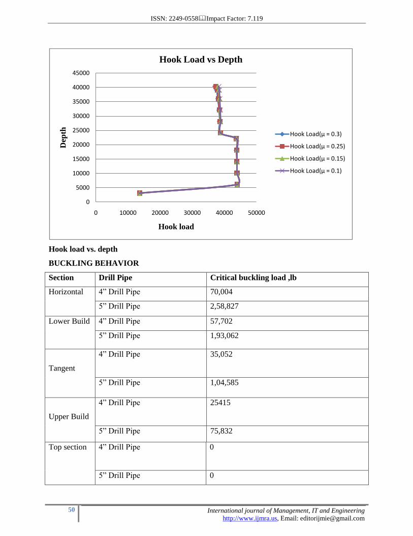
Hook load vs. depth
BUCKLING BEHAVIOR
Section Drill Pipe Critical buckling load ,lb
Horizontal 4” Drill Pipe 70,004
5” Drill Pipe 2,58,827
Lower Build 4” Drill Pipe 57,702
5” Drill Pipe 1,93,062
Tangent
4” Drill Pipe 35,052
5” Drill Pipe 1,04,585
Upper Build
4” Drill Pipe 25415
5” Drill Pipe 75,832
Top section
4” Drill Pipe 0
5” Drill Pipe 0
0
5000
10000
15000
20000
25000
30000
35000
40000
45000
0 10000 20000 30000 40000 50000
Dep
th
Hook load
Hook Load vs Depth
Hook Load(µ = 0.3)
Hook Load(µ = 0.25)
Hook Load(µ = 0.15)
Hook Load(µ = 0.1)
ISSN: 2249-0558Impact Factor: 7.119
51 International journal of Management, IT and Engineering
http://www.ijmra.us, Email: [email protected]
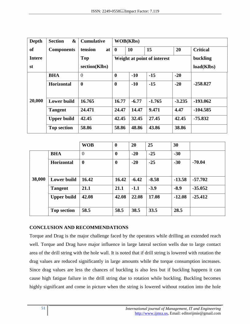
Depth
of
Intere
st
Section &
Components
Cumulative
tension at
Top
section(Klbs)
WOB(Klbs)
0 10 15 20 Critical
buckling
load(Klbs)
Weight at point of interest
20,000
BHA 0 0 -10 -15 -20
-258.827 Horizontal 0
0
-10
-15
-20
Lower build 16.765 16.77 -6.77 -1.765 -3.235 -193.062
Tangent 24.471 24.47 14.47 9.471 4.47 -104.585
Upper build 42.45 42.45 32.45 27.45 42.45 -75.832
Top section 58.86 58.86 48.86 43.86 38.86
WOB 0 20 25 30
38,000
BHA 0 0 -20 -25 -30
-70.04 Horizontal 0 0
-20
-25
-30
Lower build 16.42 16.42 -6.42 -8.58 -13.58 -57.702
Tangent 21.1 21.1 -1.1 -3.9 -8.9 -35.052
Upper build 42.08 42.08 22.08 17.08 -12.08 -25.412
Top section 58.5 58.5 38.5 33.5 28.5
CONCLUSION AND RECOMMENDATIONS
Torque and Drag is the major challenge faced by the operators while drilling an extended reach
well. Torque and Drag have major influence in large lateral section wells due to large contact
area of the drill string with the hole wall. It is noted that if drill string is lowered with rotation the
drag values are reduced significantly in large amounts while the torque consumption increases.
Since drag values are less the chances of buckling is also less but if buckling happens it can
cause high fatigue failure in the drill string due to rotation while buckling. Buckling becomes
highly significant and come in picture when the string is lowered without rotation into the hole
ISSN: 2249-0558Impact Factor: 7.119
52 International journal of Management, IT and Engineering
http://www.ijmra.us, Email: [email protected]
this increases the axial drag forces and put serious limitation to depth due to buckling and lock
up problems. But due to no rotation chances of drill string failure is less than with rotation. We
have drawn and explained the same statement above through our case analysis and drawn similar
inferences from it.
The project has a very wide scope in calculating the T&D values for different well trajectories
and helps an engineer in calculating the well economics and compare different to obtain the
optimum result.
RECOMMENDATIONS
Use of rollers in the centralizers while drilling. Centralizers have maximum O.D than the
tool joints and is contacted most with the hole resulting in high axial drag forces. With use of
rollers in the centralizers at the point of contact with the well the axial drag is converted to
rotational drag and the values of drag are reduced in much lower amounts.
Use of light weight drill pipes in the horizontal section this reduce the side weight in the
lower hole part in horizontal section and reduces the drag values.
Use of mud lubricants that have the properties of providing a thick lubricant layer
between drill pipe and hole walls reduces the T&D values.
The tapered drill string also reduces the T&D values but when used with rotation because
the critical buckling load of the less diameter drill pipe component is less and can be easily
exceeded if using without rotation. But in rotation the axial drag is converted to rotational drag
and the the buckling chances are very less.
The BHA used while drilling should be such so that well quality is maintained and the
tortuosity index remains low. The use of rotary steerable BHA is generally recommended
REFERENCES
1. K. Sonowal and B.Bennetzen, Maersk oil Qatar, P. wang, K&M group, E. Isevcan,
Schlumberger D&M, “How continuous Improvement Lead to the Longest Horizontal Well in the
World”; SPE/IADC 119506.
ISSN: 2249-0558Impact Factor: 7.119
53 International journal of Management, IT and Engineering
http://www.ijmra.us, Email: [email protected]
2. PETE 661, Drilling Engineering PPT.,” Torque and Drag calculations” from
http://www.pe.tamu.edu/schubert/public_html/PETE%20661/Lessons/Exam%20II/15.%20Torqu
e%20and%20Drag%20Calculations.ppt
3. Mitchell: “Advanced Oil well Drilling Engineering”, 10th edition MichellEngg. USA,
1995, pg405-414.
4. Mitchell computer program: “HOR_PLAN.xls” based on pg 390-392 from Mitchell:
“Advanced Oil well Drilling Engineering”.
5. Baker Hughes INTEQ: “Drilling Engineering Workbook”, December 1995, section 4-9,
4-13 to14, 4-30 to 4-32.
6. British Petroleum: “Extended Reach Drilling Guidelines”, 1996, pg 10-1 to 10-21.
7. H. Rabia: “Well Engineering and Construction”, 2001, pg 528 – 545.
8. Richard S. Carden and Robert D. Grace: “Horizontal and Directional Drilling”, Petro
Skills OGCI, TULSA, 2007, pg 9-1 to 9-14.
9. Bakers oil Tools: “Tech Facts Engineering Handbook”, pg 2-15, 2-18.