Embed Size (px)
Citation preview

Torque measuring for pulse tools

Pulse tool torque measuring Whitepaper 2
Torque measuring for pulse tools In this whitepaper, we are explaining how the TBP can measure torque using an angle reading system, as opposed to a traditional torque measurement with an inline sensor, also known as an IRTT. Exampels of different transducer types are temperature, pressure, force, position(e.g. rotary encoder) and voltage (e.g. strain gauge).
A background look at the pulse tool, and how it compares to an impact toolImpact tools – the benefits and disadvantagesImpact wrenches are based on the same principle as using a hammer to strike a wrench when tightening a bolt or screw, buildning up torque blow by blow. In a power impact wrench, the hammer is the combined mass of the rotor and the impact mechanism which delivers their kinetic energy, once per revolution, to the anvil and socket, which represent the wrench in the comparison.
The advantage of the impact wrenches is that they have a very high capacity relative to the weight and size of the tool. As the reaction torque is not greater than needed to accelerate the hammer,
the reaction force transferred back to the operator is very small. Making the impact wrench flexible and easy to use. But the comparatively high noise level of the impact wrench is a disadvantage. As is the difficulty in measuring the applied torque and consequently also the limited possibility to achieve accurate torque control.
Consequently, the impact wrench is an ideal tool for loosening rust and stuck bolts in maintenance work in chemical plants, refineries and other heavy industries. They are also suitable for a variety of applications that don’t require the highest degree of accuracy.
Pulse tools – lightweight and productiveThe hydraulic pulse tool has all of the advantages you will benefit from an impact wrench, in other words, the high speed and power from a lightweight and handy tool – without reaction forces.
In pulse tools the torque is built up via hydraulic cushion mechanism, instead of metal to metal raw blows, providing a softer, more controlled pulse. This makes for low noise, minimum vibration This accuracy is achieved by the hydraulic pulse shape mechanism inside the pulse unit. The pulse tool has a consistent torque level and a good correlation between torque and clamp force.
The handiness, speed and low noise and vibration levels together with the torque accuracy, makes the pulse tool very popular in the production industry. Including the Motor Vehicle Industry. Long service life-time and simple maintenance requirements are other benefits adding to its popularity.
Productivity is important and the pulse tool delivers high speed, meaning short cycle times for hard to semi-soft joints. It is a one-hand tool with high power-to-weight ratio.
The advantage of the impact wrenches is that they have a very high capacity relative to the weight and size of the tool. (LMS08 HR)
the pulse tool delivers high speed, meaning short cycle times for hard to semi-soft joints. (EP8 PTI HR13)

Pulse tool torque measuring Whitepaper 3
A look at what it is separating two common, but different, types of transducersA transducer is a device that converts one form of energy to another. Usually a transducer converts a signal in one form of energy to a signal in another.
Strain gaugeA Strain gauge takes advantage of the physical property of electrical conductance. When an electrical conductor is stretched or compressed within the limits of its elasticity without breaking or permanently deforming, it will become
narrower or thicker. Affecting its electrical resistance making it increase or decrease. The resistive elements are placed in a Wheatstone bridge, around a shaft, to give best conditions to measure torsion of the shaft.
A strain gauge used as a strain gauge tightening torque transducer measurement device
Straingauge
Strain, torsion of the shaft, gives elongation of the resistive element.
Gauge factor correlates the elongation to the resistive change, i.e. the change in potential over the Wheatstone bridge.
Tool torque calibration correlates the change in potential to the torque in the transducer and �nally to the torque on the out-going shaft of the tool.
A low-pass �lter is essential to eliminate noise and disturbance (both from mechanical imperfections as well as electrical transformations) from the torque signal.
Filter characteristics to be speci�ed for each tightening strategy.
Sending an output to the operator and informing about the torque.
Input OutputTorque evaluation
Gaugefactor
Tool torquecalibration Filter Torque
Strain gauge tightening torque transducer (IRTT)

Pulse tool torque measuring Whitepaper 4
A rotary encoder used as a rotary encoder tightening torque transducer measurement device
Rotary encoderA Rotary encoder – also called a shaft encoder – is an electromechanical device that converts the angular position or motion of a shaft or axle, to an analog or digital signal. There are two main types of Rotary encoders: Absolute and Incremental (relative).
The output of Absolute encoders indicates the current position of the shaft while the output of the Incremental encoder provides information on the motion of the shaft. Which is then typically further processed elsewhere into information such as speed, distance and position.
Using a rotary encoder as a rotary encoder tightening torque transducer measurement device, is patented by Atlas Copco (RRE).
Both methods of measuring torque, are based on measuring something else – that is then transformed into torque via a number of steps.
The diagram with the four pulses shows torque signal from the two methods simultaneously measured.
Rotary encoder
The rotary transducer gives position in angle.
The drive unit has speci�c mass of inertia.
The CPU clock gives an accurate time.
All together this information is enough for the system to evaluate the torque.
A low-pass �lter is essential to eliminate noise and disturbance (both from mechanical imperfections as well as electrical transformations) from the torque signal.
Sending an output to the operator and informing about the torque.
Input OutputTorque evaluation
Rotation Calculate speed TorqueCalculate
accelerationCalculate
torque & �lter
Torq
ue [N
m]
Time [ms]
70
60
50
40
30
20
10
0
0 2 4 6 8 10
Strain gauge torque transducer (IRTT)IRTT filtered 850 HzRotary encoder torque transducer (RRE in TBP)
Pulse tool torque measuring Whitepaper 5
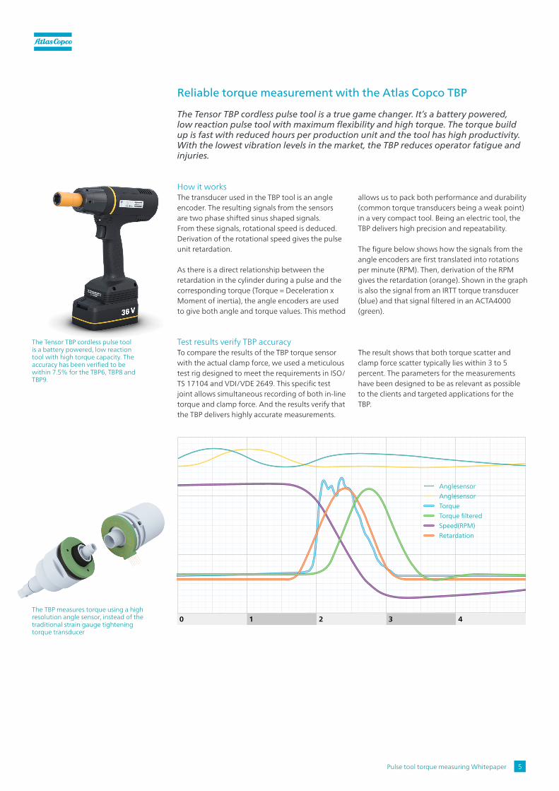
The Tensor TBP cordless pulse tool is a battery powered, low reaction tool with high torque capacity. The accuracy has been verified to be within 7.5% for the TBP6, TBP8 and TBP9.
The TBP measures torque using a high resolution angle sensor, instead of the traditional strain gauge tightening torque transducer
Reliable torque measurement with the Atlas Copco TBP
The Tensor TBP cordless pulse tool is a true game changer. It’s a battery powered, low reaction pulse tool with maximum flexibility and high torque. The torque build up is fast with reduced hours per production unit and the tool has high productivity. With the lowest vibration levels in the market, the TBP reduces operator fatigue and injuries.
How it worksThe transducer used in the TBP tool is an angle encoder. The resulting signals from the sensors are two phase shifted sinus shaped signals. From these signals, rotational speed is deduced. Derivation of the rotational speed gives the pulse unit retardation.
As there is a direct relationship between the retardation in the cylinder during a pulse and the corresponding torque (Torque = Deceleration x Moment of inertia), the angle encoders are used to give both angle and torque values. This method
allows us to pack both performance and durability (common torque transducers being a weak point) in a very compact tool. Being an electric tool, the TBP delivers high precision and repeatability.
The figure below shows how the signals from the angle encoders are first translated into rotations per minute (RPM). Then, derivation of the RPM gives the retardation (orange). Shown in the graph is also the signal from an IRTT torque transducer (blue) and that signal filtered in an ACTA4000 (green).
Test results verify TBP accuracy To compare the results of the TBP torque sensor with the actual clamp force, we used a meticulous test rig designed to meet the requirements in ISO/ TS 17104 and VDI/VDE 2649. This specific test joint allows simultaneous recording of both in-line torque and clamp force. And the results verify that the TBP delivers highly accurate measurements.
The result shows that both torque scatter and clamp force scatter typically lies within 3 to 5 percent. The parameters for the measurements have been designed to be as relevant as possible to the clients and targeted applications for the TBP.
0 1 2 3 4
AnglesensorAnglesensorTorque
RetardationSpeed(RPM)Torque filtered

Pulse tool torque measuring Whitepaper 6
Conclusion
Although there are different ways and methods of measuring torque, they come to the same conclusion. Your choice of method can therefore differ. But your results will be the same. As seen in this whitepaper where we have compared the traditional strain gauge and our new TBP sensor.
Different methods and tools Building up torque by raw blows with an impact wrench will give you a satisfying result and a relatively small reaction force on the operator. But although it is flexible and easy to use, the noise level is a disadvantage. As is the fact that the means of measuring and controlling accurate torque is limited.
Building up torque with a pulse tools, means a softer and controlled pulse where a hydraulic pulse shaping mechanism replaces the raw metal to metal blows. It is efficient, simple, productive and ergonomic. And it is safe.
A combination of great results To achieve a tightening where impact on operator is low, accuracy is high and where results can be controlled and measured in a reliable way – the Atlas Copco TBP cordless pulse tool is highly recommended.
Test results verify TBP accuracy To compare the results of the TBP torque sensor with the actual clamp force, we used a meticulous test rig designed to meet the requirements in ISO/TS 17104 and VDI/VDE 2649. This specific test joint allows simultaneous recording of both in-line torque and clamp force. And the results verify that the TBP delivers highly accurate measurements.
The result shows that both torque scatter and clamp force scatter typically lies within 3 to 5 percent. The parameters for the measurements have been designed to be as relevant as possible to the clients and targeted applications for the TBP.