Embed Size (px)
Citation preview
1856 IEEE TRANSACTIONS ON CONTROL SYSTEMS TECHNOLOGY, VOL. 25, NO. 5, SEPTEMBER 2017
Torque Observer-Based Control of Self-Energizing Clutch Actuatorfor Dual Clutch Transmission
Jiwon J. Oh, Jeong Soo Eo, and Seibum B. Choi
Abstract— Using an adaptive sliding mode control schemebased on the dual clutch torque observer, this brief proposesa novel strategy to control the clutch engagement for the dualclutch transmission (DCT) equipped with the self-energizingclutch actuator. The contribution of this brief is twofold. A slidingmode tracking controller for the actuator motor position isdeveloped by using the information provided by the torqueobserver designed to estimate the torque transferred througheach clutch of the DCT. Then, the adaptive strategy to activelyalter the target position command to compensate for the modeluncertainty or disturbance is proposed. The actuator positiontracking control accuracy improvement attained by using theadaptive sliding mode controller and, most crucially, the abilityfor the integrated controller to cope with the system disturbanceare verified in an integrated manner via actual experiments usingthe driveline test bench.
Index Terms— Clutch actuator, driveline, dual clutchtransmission (DCT), torque-tracking control, vehicle.
I. INTRODUCTION
DUE TO THE scarcity of energy and the environmentalissues, the needs for improving the vehicle powertrain
efficiency by replacing the hydraulic coupling by physicalengagement [1]–[4] have increased, and the dual clutch trans-mission (DCT) [5] has been gaining popularity. With carefullydesigned clutch actuator control methods for DCTs to optimizethe clutch slip and shift jerk [6], [7], the fuel economysimilar or higher than that of the manual transmission can bereached, as well as the convenience of automatic gear shiftsfor the driver and potential for further modification, such ashybridization of powertrain [8]–[11].
The weakness of the conventional DCT, however, is inthe actuator. To ensure satisfactory control performance ofthe clutch engagement force by reducing the sensitivity of theengagement force variation, diaphragm springs are installedin the dry-type clutch package [2]. This works against the
Manuscript received April 12, 2016; revised June 21, 2016; acceptedOctober 16, 2016. Date of publication November 9, 2016; date of currentversion August 7, 2017. Manuscript received in final form October 20, 2016.This work was supported in part by the MSIP Ministry of Science, ICT andFuture Planning, Korea, under the ITRC Information Technology ResearchCenter support program Grant IITP-2016-H8601-16-1005 supervised by theIITP Institute for Information & communications Technology Promotion,the BK21 plus program, and the National Research Foundation of Korea(NRF) grant funded by the Korea government (MSIP) Grant 2010-0028680.Recommended by Associate Editor E. Usai. (Corresponding author: SeibumB. Choi.)
J. J. Oh and S. B. Choi are with KAIST, Daejeon 34141, South Korea(e-mail: [email protected]; [email protected]).
J. S. Eo is with Hyundai Motor Company, Hwaseong 18280, South Korea(e-mail: [email protected]).
Color versions of one or more of the figures in this paper are availableonline at http://ieeexplore.ieee.org.
Digital Object Identifier 10.1109/TCST.2016.2620421
actuation efficiency by leading to higher energy consumptionin the clutch actuator via having to travel through longerdisplacement to reach the desired engagement force.
As a resolution for this issue, this brief selected the controltarget as the self-energizing clutch actuator (SECA), whichreplaces the diaphragm spring in a conventional dry-clutchsystem [6]. Here, the torque-monitoring control methodologyis proposed to overcome the system’s oversensitivity. Suchcombination can lead to both clutch actuation efficiencyimprovement and shift quality improvement in addition to thebenefits of the conventional DCTs.
Actuator controllers designed in most of the previous effortstake the form of pure position-based control [2], [6], [12], [13].However, the consistency in tracking performance can beseverely degraded due to the deviation of the system parameterfrom the nominal values, such as variation in the frictionproperty or elasticity constant of the hardware [14], especiallyfor the system in which diaphragm spring is eliminated [6].The influence of clutch wear and thermal variation may alsocontribute to the uncertainty [15], [16].
As an alternative, strategies to control the clutch based onthe clutch slip information have been previously developed aswell [7], [17]–[19]. However, such method still is unable totrack the desired torque under the influence of load torquedisturbances, and to monitor the torque transferred throughboth each clutch in the driveline with DCT. Also, theirrule-based control strategies are overly generalized.
Model-based control methods are proposed as well.However, the controller is built based on the ideal assumptionabout the model accuracy [20], and it largely depends onthe offline identification of the clutch’s torque transmissibilitytable [21], [22].
So this brief suggests an adaptive method for the torque-tracking control by making use of the dual clutch torqueobserver, which was developed in [23]. The main contributionof this brief is the design of controller with the improvedclutch transferred torque tracking ability when error existsin the clutch friction parameter. This brief also provides thetheoretical and empirical analysis of the closed-loop systemconsisting of the observer and controller.
The contents are organized as follows. Section II firstdescribes the control target. Section III provides details on thecontroller algorithm, which includes the kissing point identi-fication, position tracking controller, and adaptive scheme fortorque-tracking control. In Section IV, the experiment resultsfor each algorithm introduced in Section III are discussed, aswell as the test bench experiment results obtained by usingthe integrated controller. Through testing the performance ofthe proposed actuator controller, the torque tracking ability
1063-6536 © 2016 IEEE. Personal use is permitted, but republication/redistribution requires IEEE permission.See http://www.ieee.org/publications_standards/publications/rights/index.html for more information.
OH et al.: TORQUE OBSERVER-BASED CONTROL OF SECA FOR DCT 1857
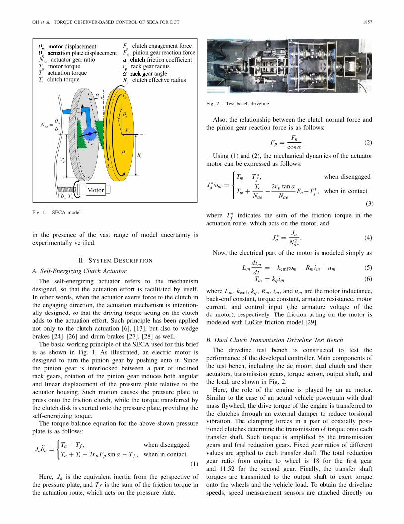
Fig. 1. SECA model.
in the presence of the vast range of model uncertainty isexperimentally verified.
II. SYSTEM DESCRIPTION
A. Self-Energizing Clutch Actuator
The self-energizing actuator refers to the mechanismdesigned, so that the actuation effort is facilitated by itself.In other words, when the actuator exerts force to the clutch inthe engaging direction, the actuation mechanism is intention-ally designed, so that the driving torque acting on the clutchadds to the actuation effort. Such principle has been appliednot only to the clutch actuation [6], [13], but also to wedgebrakes [24]–[26] and drum brakes [27], [28] as well.
The basic working principle of the SECA used for this briefis as shown in Fig. 1. As illustrated, an electric motor isdesigned to turn the pinion gear by pushing onto it. Sincethe pinion gear is interlocked between a pair of inclinedrack gears, rotation of the pinion gear induces both angularand linear displacement of the pressure plate relative to theactuator housing. Such motion causes the pressure plate topress onto the friction clutch, while the torque transferred bythe clutch disk is exerted onto the pressure plate, providing theself-energizing torque.
The torque balance equation for the above-shown pressureplate is as follows:
Ja θa ={
Ta − T f , when disengaged
Ta + Tc − 2rp Fp sin α − T f , when in contact.
(1)
Here, Ja is the equivalent inertia from the perspective ofthe pressure plate, and T f is the sum of the friction torque inthe actuation route, which acts on the pressure plate.
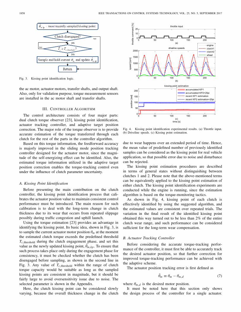
Fig. 2. Test bench driveline.
Also, the relationship between the clutch normal force andthe pinion gear reaction force is as follows:
Fp = Fn
cos α. (2)
Using (1) and (2), the mechanical dynamics of the actuatormotor can be expressed as follows:
J ∗a ωm =
⎧⎪⎨⎪⎩
Tm − T ∗f , when disengaged
Tm + Tc
Nae− 2rp tan α
NaeFn −T ∗
f , when in contact
(3)
where T ∗f indicates the sum of the friction torque in the
actuation route, which acts on the motor, and
J ∗a = Ja
N2ae
. (4)
Now, the electrical part of the motor is modeled simply as
Lmdim
dt= −kemfωm − Rmim + um (5)
Tm = kqim (6)
where Lm , kemf, kq , Rm , im , and um are the motor inductance,back-emf constant, torque constant, armature resistance, motorcurrent, and control input (the armature voltage of thedc motor), respectively. The friction acting on the motor ismodeled with LuGre friction model [29].
B. Dual Clutch Transmission Driveline Test Bench
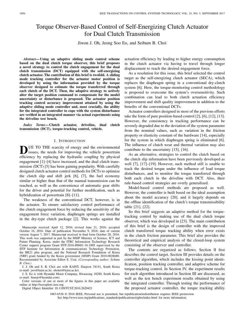
The driveline test bench is constructed to test theperformance of the developed controller. Main components ofthe test bench, including the ac motor, dual clutch and theiractuators, transmission gears, torque sensor, output shaft, andthe load, are shown in Fig. 2.
Here, the role of the engine is played by an ac motor.Similar to the case of an actual vehicle powertrain with dualmass flywheel, the drive torque of the engine is transferred tothe clutches through an external damper to reduce torsionalvibration. The clamping forces in a pair of coaxially posi-tioned clutches determine the transmission of torque onto eachtransfer shaft. Such torque is amplified by the transmissiongears and final reduction gears. Fixed gear ratios of differentvalues are applied to each transfer shaft. The total reductiongear ratio from engine to wheel is 18 for the first gearand 11.52 for the second gear. Finally, the transfer shafttorques are transmitted to the output shaft to exert torqueonto the wheels and the vehicle load. To obtain the drivelinespeeds, speed measurement sensors are attached directly on
1858 IEEE TRANSACTIONS ON CONTROL SYSTEMS TECHNOLOGY, VOL. 25, NO. 5, SEPTEMBER 2017
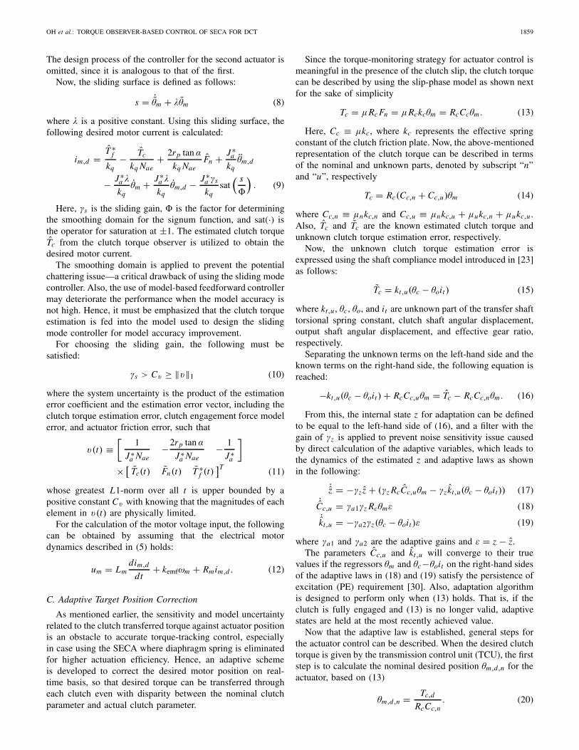
Fig. 3. Kissing point identification logic.
the ac motor, actuator motors, transfer shafts, and output shaft.Also, only for validation purpose, torque measurement sensorsare installed in the ac motor shaft and transfer shafts.
III. CONTROLLER ALGORITHM
The control architecture consists of four major parts:dual clutch torque observer [23], kissing point identification,actuator tracking controller, and adaptive target positioncorrection. The major role of the torque observer is to provideaccurate estimation of the torque transferred through eachclutch for the rest of the parts in the controller algorithm.
Based on this torque information, the feedforward accuracyis majorly improved in the sliding mode position trackingcontroller designed for the actuator motor, since the magni-tude of the self-energizing effect can be identified. Also, theestimated torque information utilized in the adaptive targetposition correction enables the torque-tracking control evenunder the influence of clutch parameter uncertainty.
A. Kissing Point Identification
Before presenting the main contribution on the clutchcontroller, the kissing point identification process that cali-brates the actuator position value to maintain consistent controlperformance must be introduced. The main reason for suchcalibration is to deal with the long-term change in clutchthickness due to its wear that occurs from repeated slippagepossibly during traffic congestion and uphill launch.
Using the torque estimation [23] provides an advantage inidentifying the kissing point. Its basic idea, shown in Fig. 3, isto sample the current actuator motor position θm at the momentthe estimated clutch torque exceeds the predefined thresholdTc,threshold during the clutch engagement phase, and set thisvalue as the newly updated kissing point, θm,kp . To ensure thatsuch process takes place only during the engagement phase forconsistency, it must be checked whether the clutch has beendisengaged before sampling, as shown in the second line inFig. 3. Any value of Tc,threshold within the range of clutchtorque capacity would be suitable as long as the sampledkissing points are consistent in magnitude, but it should befairly large to avoid oversensitivity issue due to noise. Theselected parameter is shown in the Appendix.
Here, the clutch kissing point can be considered slowlyvarying, because the overall thickness change in the clutch
Fig. 4. Kissing point identification experimental results. (a) Throttle input.(b) Driveline speeds. (c) Kissing point estimation.
due to wear happens over an extended period of time. Hence,the mean value of predefined number of previously identifiedsamples can be considered as the kissing point for real vehicleapplication, so that possible error due to noise and disturbancecan be rejected.
The kissing point estimation procedures are describedin terms of general states without distinguishing betweenclutches 1 and 2. Please note that the above-mentioned termscan be equivalently applied to the kissing point estimation ofeither clutch. The kissing point identification experiments areconducted while the engine is running, since the estimationalgorithm is based on the torque-monitoring tactics.
As shown in Fig. 4, kissing point of each clutch iseffectively identified by using the suggested algorithm, andthe estimated values are consistent over repeated trials. Thevariation in the final result of the identified kissing pointobtained this way turned out to be less than 2% of the entireclutch wear range, and such performance can be consideredsufficient for the long-term wear compensation.
B. Actuator Tracking Controller
Before considering the accurate torque-tracking perfor-mance of the controller, it must first be able to accurately trackthe desired actuator position, so that further correction forimproved torque-tracking performance can be achieved withthe adaptive scheme.
The actuator position tracking error is first defined as
θm ≡ θm − θm,d (7)
where θm,d is the desired motor position.It must be noted here that this section only shows
the design process of the controller for a single actuator.
OH et al.: TORQUE OBSERVER-BASED CONTROL OF SECA FOR DCT 1859
The design process of the controller for the second actuator isomitted, since it is analogous to that of the first.
Now, the sliding surface is defined as follows:s = ˙θm + λθm (8)
where λ is a positive constant. Using this sliding surface, thefollowing desired motor current is calculated:
im,d = T ∗f
kq− Tc
kq Nae+ 2rp tan α
kq NaeFn + J ∗
a
kqθm,d
− J ∗a λ
kqθm + J ∗
a λ
kqθm,d − J ∗
a γs
kqsat
( s
�
). (9)
Here, γs is the sliding gain, � is the factor for determiningthe smoothing domain for the signum function, and sat(·) isthe operator for saturation at ±1. The estimated clutch torqueTc from the clutch torque observer is utilized to obtain thedesired motor current.
The smoothing domain is applied to prevent the potentialchattering issue—a critical drawback of using the sliding modecontroller. Also, the use of model-based feedforward controllermay deteriorate the performance when the model accuracy isnot high. Hence, it must be emphasized that the clutch torqueestimation is fed into the model used to design the slidingmode controller for model accuracy improvement.
For choosing the sliding gain, the following must besatisfied:
γs > Cυ ≥ ‖υ‖1 (10)
where the system uncertainty is the product of the estimationerror coefficient and the estimation error vector, including theclutch torque estimation error, clutch engagement force modelerror, and actuator friction error, such that
υ(t) ≡[
1
J ∗a Nae
−2rp tan α
J ∗a Nae
− 1
J ∗a
]× [
Tc(t) Fn(t) T ∗f (t)
]T(11)
whose greatest L1-norm over all t is upper bounded by apositive constant Cυ with knowing that the magnitudes of eachelement in υ(t) are physically limited.
For the calculation of the motor voltage input, the followingcan be obtained by assuming that the electrical motordynamics described in (5) holds:
um = Lmdim,d
dt+ kemfωm + Rmim,d . (12)
C. Adaptive Target Position Correction
As mentioned earlier, the sensitivity and model uncertaintyrelated to the clutch transferred torque against actuator positionis an obstacle to accurate torque-tracking control, especiallyin case using the SECA where diaphragm spring is eliminatedfor higher actuation efficiency. Hence, an adaptive schemeis developed to correct the desired motor position on real-time basis, so that desired torque can be transferred througheach clutch even with disparity between the nominal clutchparameter and actual clutch parameter.
Since the torque-monitoring strategy for actuator control ismeaningful in the presence of the clutch slip, the clutch torquecan be described by using the slip-phase model as shown nextfor the sake of simplicity
Tc = μRc Fn = μRckcθm = RcCcθm . (13)
Here, Cc ≡ μkc, where kc represents the effective springconstant of the clutch friction plate. Now, the above-mentionedrepresentation of the clutch torque can be described in termsof the nominal and unknown parts, denoted by subscript “n”and “u”, respectively
Tc = Rc(Cc,n + Cc,u)θm (14)
where Cc,n ≡ μnkc,n and Cc,u ≡ μnkc,u + μukc,n + μukc,u .Also, Tc and Tc are the known estimated clutch torque andunknown clutch torque estimation error, respectively.
Now, the unknown clutch torque estimation error isexpressed using the shaft compliance model introduced in [23]as follows:
Tc = kt,u(θc − θoit ) (15)
where kt,u , θc, θo, and it are unknown part of the transfer shafttorsional spring constant, clutch shaft angular displacement,output shaft angular displacement, and effective gear ratio,respectively.
Separating the unknown terms on the left-hand side and theknown terms on the right-hand side, the following equation isreached:
−kt,u(θc − θoit ) + RcCc,uθm = Tc − RcCc,nθm . (16)
From this, the internal state z for adaptation can be definedto be equal to the left-hand side of (16), and a filter with thegain of γz is applied to prevent noise sensitivity issue causedby direct calculation of the adaptive variables, which leads tothe dynamics of the estimated z and adaptive laws as shownin the following:
˙z = −γz z + (γz RcCc,uθm − γz kt,u(θc − θoit)) (17)˙Cc,u = γa1γz Rcθmε (18)˙kt,u = −γa2γz(θc − θoit )ε (19)
where γa1 and γa2 are the adaptive gains and ε = z − z.The parameters Cc,u and kt,u will converge to their true
values if the regressors θm and θc−θoit on the right-hand sidesof the adaptive laws in (18) and (19) satisfy the persistence ofexcitation (PE) requirement [30]. Also, adaptation algorithmis designed to perform only when (13) holds. That is, if theclutch is fully engaged and (13) is no longer valid, adaptivestates are held at the most recently achieved value.
Now that the adaptive law is established, general steps forthe actuator control can be described. When the desired clutchtorque is given by the transmission control unit (TCU), the firststep is to calculate the nominal desired position θm,d,n for theactuator, based on (13)
θm,d,n = Tc,d
RcCc,n. (20)
1860 IEEE TRANSACTIONS ON CONTROL SYSTEMS TECHNOLOGY, VOL. 25, NO. 5, SEPTEMBER 2017
Here, Tc,d is the desired clutch torque command generatedby the vehicle TCU. Now, in order to compensate for themodel uncertainty in the clutch friction coefficient and clutchdisk spring constant, the nominal desired position θm,d isobtained by rescaling θm,d,n with the correction factor η
θm,d = ηθm,d,n. (21)
The dynamics of the correction factor is described next, usinga filter with the appropriate gain γη
η = γη
(Tc,d
Rc(Cc,n + Cc,u)− θm,d
). (22)
The modification of the reference position is conducted ina separate step from the adaptation, so that the adaptive iden-tification can be completed while (13) holds, without causingthe driveline oscillation induced from rigorously modifyingthe reference position trajectory.
Finally, the desired actuator position obtained this way isused to calculate the actuator input, based on (12).
Now select a Lyapunov function as
V = 1
2ε2 + 1
2s2 + 1
2γa1C2
c,u + 1
2γa2k2
t,u (23)
where Cc,u ≡ Cc,u − Cc,u and kt,u ≡ kt,u − kt,u .Differentiating the Lyapunov function with respect to time
leads to
V = εε + ss + 1
γa1Cc,u
˙Cc,u + 1
γa2kt,u
˙kt,u
= −γzε2 + Cc,u
(γz Rcθmε − 1
γa1
˙Cc,u
)
+ kt,u
(−γz(θc − θoit )ε − 1
γa2
˙kt,u
)
+ s(υ − γssat
( s
�
))∵
= −γzε2 + υs − γsssat
( s
�
)∵ (18) and (19)
≤ 0 ∵ (10), given |s| ≥ �. (24)
Since V is negative semidefinite, ε, s, Cc,u , and kt,u arebounded. Now, the second derivative of the Lyapunov functionwith respect to time is calculated as shown in the following:
V = −2γzεε + (υs + υ s) − γs
(ssat
( s
�
)+ s
d
dt
(sat
( s
�
))).
(25)
With the previously obtained results and the assumption thatυ is also bounded in physical sense, it can be shown that ε,s, Cc,u , and kt,u converge to zero as t → ∞ by applyingBarbalat’s lemma [31], as long as θm and θc − θoit satisfy thePE requirement [30].
IV. EXPERIMENT
Experiments are conducted by using actual driveline testbench to test the performance of the algorithms proposed inthis brief. MicroAutobox dSPACE 1401 is used to run thecontrol software and to process the signals from the sensors.
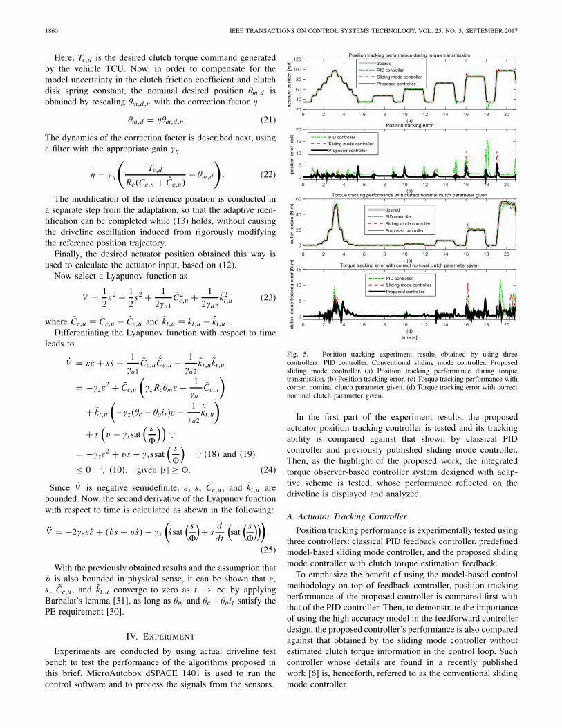
Fig. 5. Position tracking experiment results obtained by using threecontrollers. PID controller. Conventional sliding mode controller. Proposedsliding mode controller. (a) Position tracking performance during torquetransmission. (b) Position tracking error. (c) Torque tracking performance withcorrect nominal clutch parameter given. (d) Torque tracking error with correctnominal clutch parameter given.
In the first part of the experiment results, the proposedactuator position tracking controller is tested and its trackingability is compared against that shown by classical PIDcontroller and previously published sliding mode controller.Then, as the highlight of the proposed work, the integratedtorque observer-based controller system designed with adap-tive scheme is tested, whose performance reflected on thedriveline is displayed and analyzed.
A. Actuator Tracking Controller
Position tracking performance is experimentally tested usingthree controllers: classical PID feedback controller, predefinedmodel-based sliding mode controller, and the proposed slidingmode controller with clutch torque estimation feedback.
To emphasize the benefit of using the model-based controlmethodology on top of feedback controller, position trackingperformance of the proposed controller is compared first withthat of the PID controller. Then, to demonstrate the importanceof using the high accuracy model in the feedforward controllerdesign, the proposed controller’s performance is also comparedagainst that obtained by the sliding mode controller withoutestimated clutch torque information in the control loop. Suchcontroller whose details are found in a recently publishedwork [6] is, henceforth, referred to as the conventional slidingmode controller.
OH et al.: TORQUE OBSERVER-BASED CONTROL OF SECA FOR DCT 1861
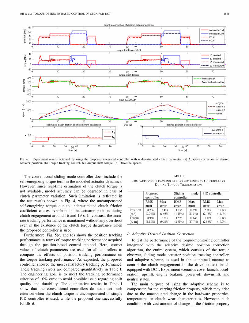
Fig. 6. Experiment results obtained by using the proposed integrated controller with underestimated clutch parameter. (a) Adaptive correction of desiredactuator position. (b) Torque tracking control. (c) Output shaft torque. (d) Driveline speeds.
The conventional sliding mode controller does include theself-energizing torque term in the modeled actuator dynamics.However, since real-time estimation of the clutch torque isnot available, model accuracy can be degraded in case ofclutch parameter variation. Such limitation is reflected inthe test results shown in Fig. 4, where the uncompensatedself-energizing torque due to underestimated clutch frictioncoefficient causes overshoot in the actuator position duringclutch engagement around 16 and 19 s. In contrast, the accu-rate tracking performance is maintained without any overshooteven in the existence of the clutch torque disturbance whenthe proposed controller is used.
Furthermore, Fig. 5(c) and (d) shows the position trackingperformance in terms of torque tracking performance acquiredthrough the position-based control method. Here, correctvalues of clutch parameters are used for all controllers tocompare the effects of position tracking performance onthe torque tracking performance. As expected, the proposedcontroller showed the most satisfactory tracking performance.These tracking errors are compared quantitatively in Table I.The engineering goal is to meet the tracking performancecriterion of 10% error to avoid possible issue regarding shiftquality and durability. The quantitative results in Table Ishow that the conventional controllers do not meet suchcriterion when the clutch torque is uncompensated or simplePID controller is used, while the proposed one successfullyfulfills it.
TABLE I
COMPARISON OF TRACKING ERRORS OBTAINED BY CONTROLLERSDURING TORQUE TRANSMISSION
B. Adaptive Desired Position Correction
To test the performance of the torque-monitoring controllerintegrated with the adaptive desired position correctionalgorithm, the entire system, which consists of the torqueobserver, sliding mode actuator position tracking controller,and adaptive scheme, is used in the combined manner tocontrol the clutch engagement in the driveline test benchequipped with DCT. Experiment scenarios cover launch, accel-eration, upshift, engine braking, power-off downshift, andneutral states.
The main purpose of using the adaptive scheme is tocompensate for the varying friction property, which may arisedue to the unaccounted change in the hardware properties,temperature, or clutch wear characteristics. However, suchcondition with vast amount of change in the friction property
1862 IEEE TRANSACTIONS ON CONTROL SYSTEMS TECHNOLOGY, VOL. 25, NO. 5, SEPTEMBER 2017
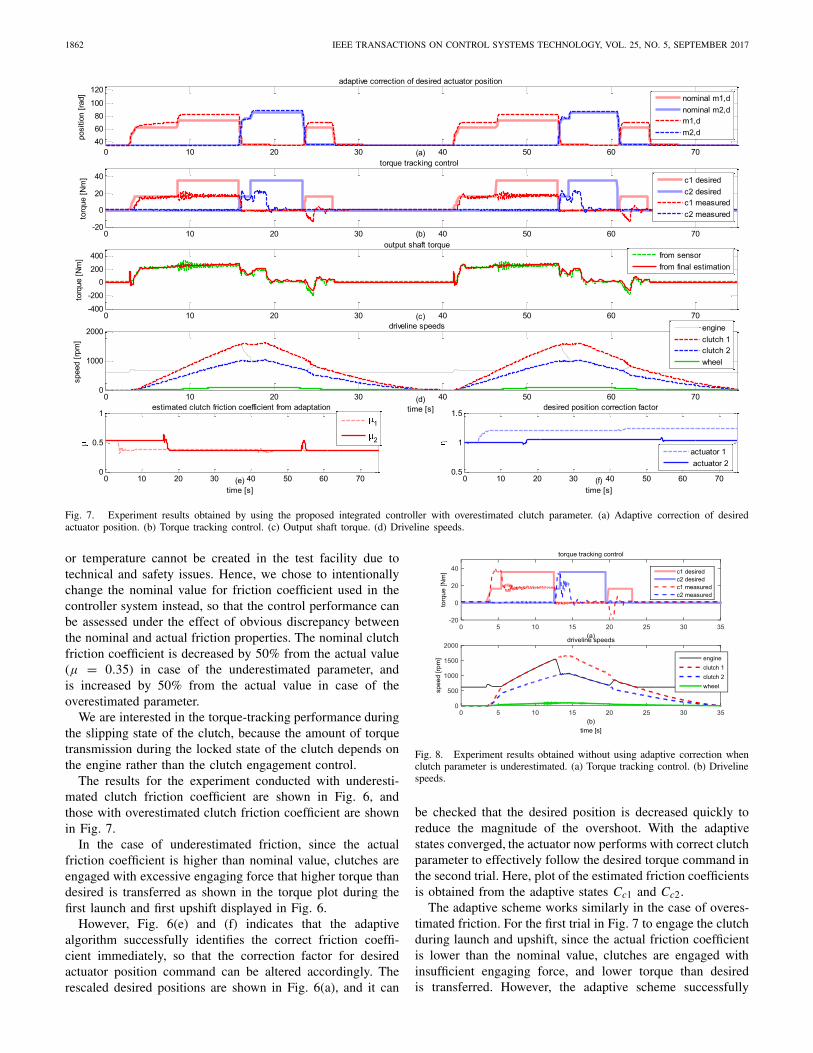
Fig. 7. Experiment results obtained by using the proposed integrated controller with overestimated clutch parameter. (a) Adaptive correction of desiredactuator position. (b) Torque tracking control. (c) Output shaft torque. (d) Driveline speeds.
or temperature cannot be created in the test facility due totechnical and safety issues. Hence, we chose to intentionallychange the nominal value for friction coefficient used in thecontroller system instead, so that the control performance canbe assessed under the effect of obvious discrepancy betweenthe nominal and actual friction properties. The nominal clutchfriction coefficient is decreased by 50% from the actual value(μ = 0.35) in case of the underestimated parameter, andis increased by 50% from the actual value in case of theoverestimated parameter.
We are interested in the torque-tracking performance duringthe slipping state of the clutch, because the amount of torquetransmission during the locked state of the clutch depends onthe engine rather than the clutch engagement control.
The results for the experiment conducted with underesti-mated clutch friction coefficient are shown in Fig. 6, andthose with overestimated clutch friction coefficient are shownin Fig. 7.
In the case of underestimated friction, since the actualfriction coefficient is higher than nominal value, clutches areengaged with excessive engaging force that higher torque thandesired is transferred as shown in the torque plot during thefirst launch and first upshift displayed in Fig. 6.
However, Fig. 6(e) and (f) indicates that the adaptivealgorithm successfully identifies the correct friction coeffi-cient immediately, so that the correction factor for desiredactuator position command can be altered accordingly. Therescaled desired positions are shown in Fig. 6(a), and it can
Fig. 8. Experiment results obtained without using adaptive correction whenclutch parameter is underestimated. (a) Torque tracking control. (b) Drivelinespeeds.
be checked that the desired position is decreased quickly toreduce the magnitude of the overshoot. With the adaptivestates converged, the actuator now performs with correct clutchparameter to effectively follow the desired torque command inthe second trial. Here, plot of the estimated friction coefficientsis obtained from the adaptive states Cc1 and Cc2.
The adaptive scheme works similarly in the case of overes-timated friction. For the first trial in Fig. 7 to engage the clutchduring launch and upshift, since the actual friction coefficientis lower than the nominal value, clutches are engaged withinsufficient engaging force, and lower torque than desiredis transferred. However, the adaptive scheme successfully
OH et al.: TORQUE OBSERVER-BASED CONTROL OF SECA FOR DCT 1863
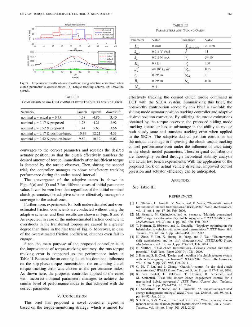
Fig. 9. Experiment results obtained without using adaptive correction whenclutch parameter is overestimated. (a) Torque tracking control. (b) Drivelinespeeds.
TABLE II
COMPARISON OF rms ON-COMING CLUTCH TORQUE TRACKING ERROR
converges to the correct parameter and rescales the desiredactuator position, so that the clutch effectively transfers thedesired amount of torque, immediately after insufficient torqueis detected by the torque observer. Then, during the secondtrial, the controller manages to show satisfactory trackingperformance during the entire tested interval.
The convergence of the adaptive states is shown inFigs. 6(e) and (f) and 7 for different cases of initial parametervalue. It can be seen here that regardless of the initial nominalclutch parameter, the adaptive scheme effectively manages toconverge to the actual ones.
Furthermore, experiments for both underestimated and over-estimated friction coefficients are conducted without using theadaptive scheme, and their results are shown in Figs. 8 and 9.As expected, in case of the underestimated friction coefficient,overshoots in the transferred torques are caused to a greaterdegree than those in the first trial of Fig. 6. Moreover, in caseof the overestimated friction coefficient, clutches even fail toengage.
Since the main purpose of the proposed controller is inthe improvement of torque-tracking accuracy, the rms torquetracking error is compared as the performance index inTable II. Because the on-coming clutch has dominant influenceon the slip-phase torque transmission, the on-coming clutchtorque tracking error was chosen as the performance index.As shown here, the proposed controller applied to the caseswith incorrect nominal parameters manages to achieve thesimilar level of performance index to that achieved with thecorrect parameter.
V. CONCLUSION
This brief has proposed a novel controller algorithmbased on the torque-monitoring strategy, which is aimed for
TABLE III
PARAMETERS AND TUNING GAINS
effectively tracking the desired clutch torque command inDCT with the SECA system. Summarizing this brief, thenoteworthy contribution served by this brief is twofold: thesliding mode actuator position tracking controller and adaptivedesired position correction. By utilizing the torque estimationsobtained by the torque observer, the proposed sliding modetracking controller has its advantage in the ability to reduceboth steady state and transient tracking error when appliedto the SECA. The adaptive desired position correction hasthe unique advantage in improving the clutch torque trackingcontrol performance even under the influence of uncertaintyin the clutch model parameters. These original contributionsare thoroughly verified through theoretical stability analysisand actual test bench experiments. With the application of theproposed work on actual vehicle driveline, improved controlprecision and actuator efficiency can be anticipated.
APPENDIX
See Table III.
REFERENCES
[1] L. Glielmo, L. Iannelli, V. Vacca, and F. Vasca, “Gearshift controlfor automated manual transmissions,” IEEE/ASME Trans. Mechatronics,vol. 11, no. 1, pp. 17–26, Feb. 2006.
[2] M. Pisaturo, M. Cirrincione, and A. Senatore, “Multiple constrainedMPC design for automotive dry clutch engagement,” IEEE/ASME Trans.Mechatronics, vol. 20, no. 1, pp. 469–480, Feb. 2015.
[3] T. Hofman, S. Ebbesen, and L. Guzzella, “Topology optimization forhybrid electric vehicles with automated transmissions,” IEEE Trans. Veh.Technol., vol. 61, no. 6, pp. 2442–2451, Jul. 2012.
[4] K. Zhao, Y. Liu, X. Huang, R. Yang, and J. Wei, “Uninterruptedshift transmission and its shift characteristics,” IEEE/ASME Trans.Mechatronics, vol. 19, no. 1, pp. 374–383, Feb. 2014.
[5] B. Matthes, “Dual clutch transmissions—Lessons learned and futurepotential,” SAE Tech. Paper 2005-01-1021, 2005.
[6] J. Kim and S. B. Choi, “Design and modeling of a clutch actuator systemwith self-energizing mechanism,” IEEE/ASME Trans. Mechatronics,vol. 16, no. 5, pp. 953–966, Oct. 2011.
[7] C. Ni, T. Lu, and J. Zhang, “Gearshift control for dry dual-clutchtransmissions,” WSEAS Trans. Syst., vol. 8, no. 11, pp. 1177–1186, 2009.
[8] K. van Berkel, F. Veldpaus, T. Hofman, B. Vroemen, andM. Steinbuch, “Fast and smooth clutch engagement control for amechanical hybrid powertrain,” IEEE Trans. Control Syst. Technol.,vol. 22, no. 4, pp. 1241–1254, Jul. 2014.
[9] O. Sundstrom, P. Soltic, and L. Guzzella, “A transmission-actuatedenergy-management strategy,” IEEE Trans. Veh. Technol., vol. 59, no. 1,pp. 84–92, Jan. 2010.
[10] S. J. Kim, Y.-S. Yoon, S. Kim, and K.-S. Kim, “Fuel economy assess-ment of novel multi-mode parallel hybrid electric vehicle,” Int. J. Autom.Technol., vol. 16, no. 3, pp. 501–512, 2015.
1864 IEEE TRANSACTIONS ON CONTROL SYSTEMS TECHNOLOGY, VOL. 25, NO. 5, SEPTEMBER 2017
[11] W. Zhuang, X. Zhang, D. Zhao, H. Peng, and L. Wang, “Optimal designof three-planetary-gear power-split hybrid powertrains,” Int. J. Autom.Technol., vol. 17, no. 2, pp. 299–309, 2016.
[12] A. Grancharova and T. A. Johansen, “Design and comparison of explicitmodel predictive controllers for an electropneumatic clutch actuatorusing on/off valves,” IEEE/ASME Trans. Mechatronics, vol. 16, no. 4,pp. 665–673, Aug. 2011.
[13] J. Deur, V. Ivanovic, Z. Herold, M. Kostelac, and H. E. Tseng, “Dryclutch control based on electromechanical actuator position feedbackloop,” Int. J. Vehicle Design, vol. 60, no. 3, pp. 305–326, 2012.
[14] F. Vasca, L. Iannelli, A. Senatore, and G. Reale, “Torque transmissibilityassessment for automotive dry-clutch engagement,” IEEE/ASME Trans.Mechatronics, vol. 16, no. 3, pp. 564–573, Jun. 2011.
[15] A. Myklebust and L. Eriksson, “Modeling, observability, and estimationof thermal effects and aging on transmitted torque in a heavy duty truckwith a dry clutch,” IEEE/ASME Trans. Mechatronics, vol. 20, no. 1,pp. 61–72, Feb. 2015.
[16] G. Pica, C. Cervone, A. Senatore, and F. Vasca, “Temperature-dependenttorque transmissibility characteristic for automotive dry dual clutches,”in Proc. Eur. Control Conf. (ECC), 2015, pp. 2126–2131.
[17] M. Kulkarni, T. Shim, and Y. Zhang, “Shift dynamics and controlof dual-clutch transmissions,” Mech. Mach. Theory, vol. 42, no. 2,pp. 168–182, 2007.
[18] P. D. Walker, N. Zhang, and R. Tamba, “Control of gear shifts in dualclutch transmission powertrains,” Mech. Syst. Signal Process., vol. 25,no. 6, pp. 1923–1936, 2011.
[19] M. Goetz, M. C. Levesley, and D. A. Crolla, “Dynamics and controlof gearshifts on twin-clutch transmissions,” Proc. Inst. Mech. Eng.D, J. Automobile Eng., vol. 219, no. 8, pp. 951–963, 2005.
[20] J. Oh, S. B. Choi, Y. J. Chang, and J. S. Eo, “Engine clutch torqueestimation for parallel-type hybrid electric vehicles,” Int. J. Autom.Technol., vol. 18, no. 1, pp. 125–135, 2017.
[21] G. Shi, P. Dong, H. Q. Sun, Y. Liu, Y. J. Cheng, and X. Y. Xu, “Adaptivecontrol of the shifting process in automatic transmissions,” Int. J. Autom.Technol., vol. 18, no. 1, pp. 179–194, 2017.
[22] L. Glielmo, L. Iannelli, V. Vacca, and F. Vasca, “Speed control forautomated manual transmission with dry clutch,” in Proc. 43rd IEEEConf. Decision Control (CDC), vol. 2. Dec. 2014, pp. 1709–1714.
[23] J. J. Oh and S. B. Choi, “Real-time estimation of transmittedtorque on each clutch for ground vehicles with dual clutch transmis-sion,” IEEE/ASME Trans. Mechatronics, vol. 20, no. 1, pp. 24–36,Feb. 2015.
[24] R. Roberts, M. Schautt, H. Hartmann, and B. Gombert, “Model-ing and validation of the mechatronic wedge brake,” SAE Tech.Paper 2003-01-3331, 2003.
[25] L. Balogh, T. Streli, H. Nemeth, and L. Palkovics, “Modelling andsimulating of self-energizing brake system,” Vehicle Syst. Dyn., vol. 44,no. 1, pp. 368–377, 2006.
[26] H. Park and S. B. Choi, “Development of a sensorless controlmethod for a self-energizing brake system using noncircular gears,”IEEE Trans. Control Syst. Technol., vol. 21, no. 4, pp. 1328–1339,Jul. 2013.
[27] S. S. Rao and L. Cao, “Optimum design of mechanical systems involvinginterval parameters,” J. Mech. Des., vol. 124, no. 3, pp. 465–472, 2002.
[28] Y. M. Huang and J. S. Shyr, “On pressure distributions of drum brakes,”J. Mech. Des., vol. 124, no. 1, pp. 115–120, 2002.
[29] C. C. de Wit, H. Olsson, K. J. Åström, and P. Lischinsky,“A new model for control of systems with friction,”IEEE Trans. Autom. Control, vol. 40, no. 3, pp. 419–425,Mar. 1995.
[30] P. A. Ioannou and J. Sun, Robust Adaptive Control. Englewood Cliffs,NJ, USA: Prentice-Hall, 1964, p. 150.
[31] J. E. Slotine and W. Li, Applied Nonlinear Control. Englewood Cliffs,NJ, USA: Prentice-Hall, 1991.