Embed Size (px)
Citation preview

Torque-Speed Characteristics of Three Phase Squirrel CageInduction Motor
Aim
To obtain the torque-speed characteristics (T-Nr) of a three phase squirrel cage induction motor using
1. Variable voltage control
2. Variable voltage variable frequency (V/F) control
Theory
An induction motor compared to a dc motor has some major advantages such as - Absence of brushes,commutator segments, rugged construction, being cheap, lesser maintenance requirements and smallersize for the same power output. Due to these advantages induction machines have become more popularin industrial applications. For any motor load application, it is imperative to know the torque speedcharacteristic of the motor. Consider a three phase squirrel cage induction motor whose stator hasthree windings displaced in space by 120◦. When they are excited with currents that are displaced intime by 120◦, a rotating magnetic field rotating at a speed called synchronous speed Ns is set up. Thesynchronous speed, Ns is given by (1).
Ns =120f
P(1)
where, f is the frequency of the currents and P is the number of poles. If the rotor of the inductionmotor rotates at a speed, Nr, then the slip, s is defined by (2).
s =Ns −Nr
Ns
(2)
The torque developed by the induction motor is given by (3).
T =3
ωs
I22R2
s=
3
ωs
Vs2R2/s
(R1 +R2/s)2 + (X1 +X2)2 (3)
where ωs is the synchronous speed in rps, Vs is the voltage applied to the stator, I2, R2, X2 are therotor current, resistance and reactance referred to stator respectively. R1, X1 are the stator resistanceand reactance respectively. If (3) is plotted, we get the T-Nr characteristics as shown in Fig. 1. Themaximum torque developed, Tm and the slip,sm at which Tm occurs is given by (4).
Tm =3
2ωs
Vs2
R1 ±√R1
2 ± (X1 +X2)2
sm =R2√
R12 + (X1 +X2)
2
(4)
T-Nr characteristics with variable stator voltage
If voltage applied to the stator of the induction motor is varied, developed torque will vary with arelation T ∝ Vs
2. The maximum torque developed, Tm is also proportional to square of the appliedvoltage as in (4), but sm is independent of applied voltage. So, if the T-Nr characteristics is plottedfor different voltages, we get the characteristics as shown in Fig. 2.
1
T
Ns01 0
Nr
s
Tm
sm
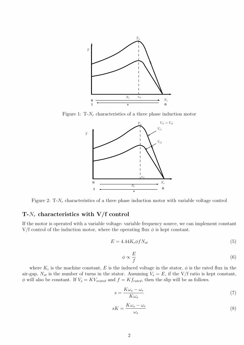
Figure 1: T-Nr characteristics of a three phase induction motor
T
Ns
Vs1 > Vs2
Nr
s01
0
Tm
Vs2
Vs1
sm
Figure 2: T-Nr characteristics of a three phase induction motor with variable voltage control
T-Nr characteristics with V/f control
If the motor is operated with a variable voltage- variable frequency source, we can implement constantV/f control of the induction motor, where the operating flux φ is kept constant.
E = 4.44KcφfNst (5)
φ ∝ E
f(6)
where Kc is the machine constant, E is the induced voltage in the stator, φ is the rated flux in theair-gap, Nst is the number of turns in the stator. Assuming Vs = E, if the V/f ratio is kept constant,φ will also be constant. If Vs = KVsrated and f = Kfrated, then the slip will be as follows.
s =Kωs − ωr
Kωs
(7)
sK =Kωs − ωr
ωs
(8)
2

where the term sK is the slip speed, that is the drop in motor speed from no load speed (Kωs).The expression for the developed torque with V/f control will be given by (9).
T =3
Kωs
I22R2
s=
3
ωs
Vs2R2/sK
(R2/Ks)2 +X22 (9)
The maximum torque developed, Tm and the slip at which Tm occurs,sm are given by (10).
Tm =3
2ωs
Vs2
X2
sm =R2
KX2
(10)
So with V/f control, the maximum torque developed is independent of K, but sm is inversely propor-tional to K. From (9), for any given torque,T , the drop in motor speed from no load speed, (sK) willbe same for any value of K. Thus , with V/f control, the T-Nr characteristics for different values of Kwill be parallel to each other as shown in Fig.3.
K = 1K = 0.5
T
0 Nr Nss
01
Figure 3: T-Nr characteristics of a three phase induction motor with V/f control
The starting torque ( for s=1), Tst is given by (11). Thus, Tst ∝ 1/K.
Tst =3
ωs
Vs2R2/K
(R2/K)2 +X22 (11)
Procedure:
Variable voltage control:
A. Connect the circuit as shown in figure 4. In this experiment the motor is loaded with a mechanicalsystem.
B. Initially no load is applied to the motor. Set the output of the autotransformer to zero and switchon the three phase supply.
C. Vary the voltage applied to the stator using autotransformer. Increase the voltage to half therated value. Increase the load slowly to get different torque and speed points to get the T-Nr
characteristics at half the rated voltage. Make sure that the motor is not loaded above its ratedcurrent.
3

Mechanical
3 phase IM
3 phase
Auto X’merA
B
C
3 phase
50 Hz
440V
A
V
Power Analyser
Power Analyser
load
Figure 4: Circuit diagram for variable voltage control
D. Now reduce the load to zero and repeat the same steps[A-C] with rated voltage applied to thestator.
E. Bring the load to zero. Then bring the autotransformer to zero position and switch off the supply.
V/f control:
A. Connect the circuit as shown in figure 5.
B. Initially no load is applied to the motor. Switch on the variable frequency drive. Set the speedat half the synchronous speed. Press the RUN button in VFD.
C. Increase the load slowly to get different torque and speed points to get the T-Nr characteristicsat K=0.5.
D. Now set the speed in VFD as the synchronous speed of the motor and repeat the same steps[A-C]to obtain the characteristics at K=1.
E. Bring the load to zero. Then turn off the VFD and switch off the supply.
A
N
Power Analyser
Power Analyser
230V
50Hz
Variable
frequency
drive
A
V
3 phase IMMechanical
load
Figure 5: Circuit diagram for V/f control
The cut section of a squirrel cage induction motor is shown in Fig.6. Separate view of the statorand rotor of an induction motor is shown in Fig.7.
4

Figure 6: Cut section of an Induction motor
(a)
(b)
Figure 7: a) Stator b) Rotor
References
[1] G. K. Dubey. Fundamentals of Electrical Drives, Alpha Science International Ltd., 2001.
This document is prepared by Neethu S. (Research Scholar, 2014 batch).
5