Embed Size (px)
Citation preview

Journal of Mechanical Research and Application JMRA
ISSN: 2251-7383, eISSN: 2251-7391
Vol. 7, No.1, 2017, 1-12
*. Ph.D student, Department of Mechanical Engineering, South Tehran Branch, Islamic Azad University, Tehran, Iran (Email address: [email protected]).09356617849
2.Ms.c , Department of Engineering, Zanjan University, Zanjan, Iran (Email address: [email protected])
Torsion of cylindrically poroelasic circular shaft with radial
inhomogeneity .some exact solutions for extruder
Mohammad Farid Khansanami1*
, Faranak Khansanami2
Received: 2017- 03- 14 Accepted: 2017- 04 - 03
Abstract: Torsion of elastic and poroelastic circular shaft of radially
inhomogeneous, cylindrically orthotropic materials is studied with
emphasis on the end effects example for extruder. To examine the
conjecture of Saint-Venant’s torsion, we consider torsion of circular shaft
with one end fixed and the other end free on which tractions that results in
a pure torque are prescribed arbitrarily over the free end surface. Exact
solutions that satisfy the prescribed boundary conditions point by point
over the entire boundary surfaces are derived in a unified manner for
cylindrically orthotropic shafts with or without radial inhomogeneity and
for their coun- terparts of Saint-Venant’s torsion. Stress diffusion due to
the end effect is examined in the light of the exact solutions.The present
study enables us to assess Saint-Venant’s principle as applied to
anisotropic, non-homogeneous poroelastic bodies in general and to
evaluate the stress diffusion in torsion of radially inhomogeneous,
cylindrically orthotropic cylinders in particular. The following
conclusions can be drawn from the analysis.
Keywords: FGM and poroelastic shaft, Radial inhomogeneity, Torsion,
extruder
1. Introduction
Torsion is one of the interesting fields for
researchers. In 1903, Prandtl [1] introduced
the stress function of the Saint-Venant torsion
and the method of membrane analogy [2]. He
presented a membrane analogy for torsional
analysis and proved the accuracy and
efficiency of his approximation. Baron [3]
studied torsion of hollow tubes by
multiplying the connected cross sections. He
used an iterative method to satisfy the
equilibrium and compatibility equations. A
computational method for calculating
torsional stiffness of multi-material bars with
arbitrary shape was studied by Li et Al. [4].
In this work, they considered additional
compatibility and equilibrium equations in
common boundaries of different materials in

2 Torsion of cylindrically poroelasic circular shaft with radial …
their formulation and, good results were
obtained. Mijak [5] considered a new method
to design an optimum shape in beams with
torsional loading. In his work, cost function
was torsional rigidity of the domain and
constraint was the constant area of the cross-
section while shape parameters were co-
ordinates of the finite element nodes along
the variable boundary. The problem was
directly solved by optimizing the cost
function with respect to the shape parameters.
He solved this problem using finite elements
(FE) method. Kubo and Sezawa [6] presented
a theory for calculating the torsional buckling
of tubes and also reported on experimental
results for rubber models. However, this
theory did not conform to experimental
results. Lundquist [7] performed extensive
experiments on the strength of aluminum
shafts under torsion reported in 1932.
Recently, Doostfatemeh et al. [8] obtained a
closed-form approximate formulation for
torsional analysis of hollow tubes with
straight and circular edges. In this work, the
problem was formulated in terms of Prandtl’s
stress function. Also, accuracy of the
formulas was verified by accurate finite
element method solutions.
In recent years, the composition of several
different materials has been often used in
structural components in order to optimize
responses of the structures subjected to
thermal and mechanical loads. Since these
pioneering works established the theory of
torsion and solved many problems in
engineering application, the torsion of a
straight bar became a classical problem in the
theory of elasticity, which was also presented
as a numerical example in a seminal paper
about the finite element method by Courant
[9]. Some analytical solutions of the
homogeneous section with various shapes are
available in the literatures [10, 11]. The
torsion of composite shafts has attracted
many researchers’ attention in the
development and application of composite
materials. Muskhelishvilli [12] presented not
only the governing equation and boundary
condition of the torsion of composite bars,
but also its solution in Fourier series for
composite section with two sub-rectangles.
This solution was extended later for multiple
rectangular composite section by Booker and
Kitipornchai [13]. Kuo and Conway [14–17]
analyzed the torsion of the composite
sections of various shapes. Packham and
Shail [18] extended their work on two-phase
fluid to the torsion of composite shafts.
Ripton [19] investigated the torsional rigidity
of composite section reinforced by fibers.
Chen et al. [20] also analyzed exactly the
torsion of composite bars. Apart from these
analytical methods, numerical methods have
also been employed to solve the torsion of the
straight bars. Ely and Zienkiewicz [21] firstly
solved the Poisson’s equation of the Prandtl’s
stress function using finite difference method,
and then they investigated the rectangular
section with and without holes. Herrmann
[22] utilized the finite element method to
calculate the warping function of the torsion
of irregular sectional shapes. The boundary
element method was applied to solve the
boundary integral equation of the warping
function of the torsion in Refs. [23–26].
Recently Poro's properties have been
developed to overcome the problems
associated with interfaces in traditional
composite materials due to the abrupt change
of the materials properties, as they
Journal of Mechanical Research and Application (JMRA), Vol.7, No. 1, 2017, 1-12 3
continuously vary with spatial coordinates
[27]. Despite of less attention paid to this
subject, Ely and Zienkiewicz [21] and
Plunkett [28] presented the governing
equation of the torsion of inhomogeneous
material before the introduction of the
conception of Poros, as there is no
engineering significance at that time. Once
the FGMs were fabricated and applied in
engineering practice, Rooney and Ferrari
[29,30] and Horgan and Chan [31] resumed
the research on the torsion of FGM bars.
More recently, Tarn and Chang [32] obtained
the exact solution of the torsion of
orthotropic inhomogeneous cylinders and
also analyzed the end effect. In particular, the
torsion problem for inhomogeneous isotropic
elastic materials has been investigated
recently in [33]. Poroelasticity is a theory that
models the interaction of deformation and
fluid flow in a fluid-saturated porous
medium. The deformation of the medium
influences the flow of the fluid and vice
versa. The theory was proposed by Biot [34-
36]. As a theoretical extension of soil
consolidation models developed to calculate
the settlement of structures placed on fluid-
saturated porous soils, The historical
development of the theory is sketched by de
Boer (1996). The theory has been widely
applied to geotechnical problems beyond soil
consolidation that are the most notably
problems in rock mechanics. There has been
recently a growing interest in the context of
non-homogeneous and/or anisotropic shaft.
Arghavan and Hematiyan[37] analyzed the
Torsion of functionally graded hollow tubes.
Batra [38] ,Horgan and Chan [39] work on
Torsion of a functionally graded cylinder;
Rooney and Ferrari [40]; Udea et al [41] and
Yaususi and Shigeyasu [42] analyzed the
Torsion and flexure of inhomogeneous
elements; Khansanami and Jabbari [43] work
on torsion of proElastic shaft.
2. Governing Equations
Stress-Stress Function Formulation[44]
The stress formulation leads to the use of a
stress function similar to the results of the
plane problem discussed. Using the
displacement form, the strain-displacement
relations give the following strain field:
(1)
)α∂
∂(
2
1y
x
wexz = (2)
(3)
The corresponding stresses follow from
Hooke’s law:
0τσσσ ==== xyzyx (4)
)α∂
∂(μτ y
x
wxz =
(5)
)α∂
∂(μτ x
y
wyz +=
(6)
Note that the strain and stress fields are
functions only of x and y. For this case, with
zero body forces, the equilibrium equations
are reduced to
0∂
∂τ
∂
∂τ=+
yx
yzxz
(7)
Rather than using the general Beltrami-
Michell compatibility equations, it is more
desirable to develop a special compatibility
relation for this particular problem. This is
easily done by simply differentiating (5) with
0==== xyzyx eeee
)α∂
∂(
2
1x
y
we yz +=
4 Torsion of cylindrically poroelasic circular shaft with radial …
respect to y and (6) regarding x and
subtracting the results to get
μα2∂
∂τ
∂
∂τ=
xy
yzxz (8)
This represents an independent relation
among the stresses developed under the
continuity conditions of w(x,y).
Relations (7) and (8) constitute the
governing equations for the stress
formulation. The coupled system pair can be
reduced by introducing a stress function
approach. For this case, the stresses are
represented in terms of the Prandtl stress
function ),(φφ yx= by
yxz∂
∂φτ = (9)
xyz
∂
∂φτ = (10)
The equilibrium equations are then
identically satisfied and the compatibility
relation gives the following relation:
μα2∂
φ∂
∂
φ∂φ∇
2
2
2
2
2 =+=yx
(11)
Thus, this single relation is the governing
equation for the problem and (11) is a
Poisson equation that is amenable to several
analytical solution techniques.
To complete the stress formulation we
now must address the boundary conditions on
the problem. As previously mentioned, the
lateral surface of the cylinder S is to be free
of tractions, and thus
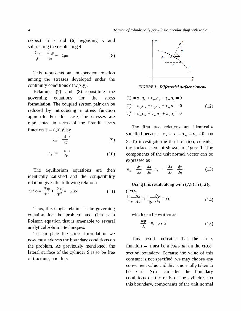
FIGURE 1 : Differential surface element.
0σττ
0τστ
0ττσ
=++=
=++=
=++=
zzyyzxxz
n
z
zzyyyxxy
n
y
zzxyyxxx
n
x
nnnT
nnnT
nnnT
(12)
The first two relations are identically
satisfied because
0τσσ ==== zxyyx n on
S. To investigate the third relation, consider
the surface element shown in Figure 1. The
components of the unit normal vector can be
expressed as
dn
dy
ds
dxn
dn
dx
ds
dyn yx ==== , (13)
Using this result along with (7,8) in (12)3
gives:
0
ds
dy
yds
dx
x
(14)
which can be written as
Sonds
d,0
φ= (15)
This result indicates that the stress
function must be a constant on the cross-
section boundary. Because the value of this
constant is not specified, we may choose any
convenient value and this is normally taken to
be zero. Next consider the boundary
conditions on the ends of the cylinder. On
this boundary, components of the unit normal

Journal of Mechanical Research and Application (JMRA), Vol.7, No. 1, 2017, 1-12 5
become 1,0 ±=== zyx nnn , and thus the
tractions simplify to
(16)
Recall that we are only interested in
satisfying the resultant end-loading
conditions, and thus the resultant force
should vanish while the moment should
reduce to a pure torque T about the z-axis.
These conditions are specified by
0∫∫ == dydxTpR
n
xx
(17-1)
0∫∫ == dydxTpR
n
yy
(17-2)
0∫∫ == dydxTpR
n
zz
(17-3)
0∫∫ == dydxyTMR
n
zx
(17-4)
0∫∫ == dydxxTMR
n
zy
(17-5)
TdydxyTxTMR
n
x
n
yz == )(∫∫ (17-6)
With 0=n
zT , conditions (17-3 to 17-5) are
automatically satisfied. Considering the first
condition in set (17), the x component of the
resultant force on the ends may be written as
dydxy
dydxdydxTR R
xz
R
n
x ∫∫ ∫∫∫∫ ∂
∂φτ ±=±= (18)
Using Green’s theorem,
∫∫∫ φ
∂
∂φs
y
R
dsndydxy
= and because
vanishes on boundary S , the integral is zero
and the resultant force Px vanishes. Similar
arguments can be used to show that the
resultant force Py will vanish. The final
end condition (17-6) involving the resultant
torque can be expressed as
dydxy
yx
xdydxyTxTTRR
n
x
n
y )∂
∂φ
∂
∂φ()( ∫∫∫∫ +== (19)
Reapplying above equation, the following
equation results from Green’s theorem
dydxdsnxdydxdydxxx
dydxx
xR
xs
RRR
∫∫∫∫∫∫∫∫∫ φφφ)φ(∂
∂
∂
∂φ== (20-1)
dydxdsnydydxdydxyy
dydxy
yR
ys
RRR
∫∫∫∫∫∫∫∫∫ φφφ)φ(∂
∂
∂
∂φ== (20-2)
0
τ
τ
=
±=
±=
n
z
yz
n
y
xz
n
x
T
T
T

6 Torsion of cylindrically poroelasic circular shaft with radial …
Because is zero on S, the boundary
integrals in (20-1 and20-2) will vanish and
relation (19) simplifies to
dydxTR
∫∫φ2= (21)
3. Results and discussion
As a simple measure to estimate the stress
disturbance from the end in a long circular
shaft, which is the distance measured from the
end beyond which the series terms contribute
only 1% in magnitude to the deformation and
stresses. In other words, the deformation and
stresses in the region beyond L from the end are
essentially inde- pendent of the load
distribution over the end surface so that the
Saint-Venant solution should be applicable.
Of course, other percentage could be chosen
for the estimation and the smallest eigenvalue
k1 should be used to determine the largest L.
Knowing λ1b= 5.1355 for a
homogeneous shaft, so
L=ln100/kλ1=0.8967b√ (22)
which suggests that the end effect is far-
reaching for strong anisotropy (c44>>c66).
Since c44 = c66 for isotropic materials, L =
0.8966b, suggesting that the stress disturbance
is indeed confined to a local region near the
end in a long homogeneous isotropic shaft.
Tables 1 and 2 show the smallest eigenvalue
λ1 associated with the parameter of the radial
inhomogeneity µ, and the characteristic
decay length L of long circular shafts in
connection with µ and the material parameter
k=√ to show the effect of
anisotropy, we take c44/ c66 = 1, 4, 16, 100 for
computation. All cases are admissible in that
they satisfy the requirement of positive-
definiteness of the strain energy. Although
c44/c66 = 100 appears to be uncommon in
practice, the value is as-
Table 1
The smallest eigenvalue for various inhomogeneity parameters
Table 2
Characteristic decay length of long circular shaft
sumed in the interest of demonstrating the
effect of strong anisotropy. Notably, the
characteristic decay length could reach as far
as 9b from the free end of a strongly
orthotropic (c44 = 100c66) circular shaft, not
to the expectation based on Saint-Venant’s
conjuncture.
µ 0 0.1 0.2 0.5 1.0 2.0 3.0
λ1b 5.135 5.262 5.388 5.763 6.380 7.588 8.771
L Isotropic c44 = 4c66 c44 = 16c66 c44 = 100c66
µ= 0 0.897b 1.794b 3.587b 8.967b
µ= 0.5 0.799b 1.598b 3.196b 7.991b
µ= 1.0 0.722b 1.447b 2.887b 7.218b

Journal of Mechanical Research and Application (JMRA), Vol.7, No. 1, 2017, 1-12 7
To examine quantitatively the Saint-
Venant conjecture, we consider two types of
torsional load prescribed over the end
surface. Load type 1: linearly distributed
load, p(r)= qr. Load type 2: tangential ring
load applied at the boundary of the circular
section, p(r) = 0.25qb2δ(r — b), where δ(r —
b) is the Dirac-delta function. Both loading
types give rise to a pure torque of the same
magnitude. While the linearly distributed
load is continuous over the end surface, the
tangential ring load is concentrated at r = b.
The influence of the radial inhomogeneity
and material anisotropy are studied by taking
the material parameters: µ= 0 (homogeneous
material), µ = 0.5 (linearly distributed radial
inhomogeneity) and µ= 1.0 (quadratically
distributed radial inhomogeneity); k= 1 (c44
= c66,isotropic material),k= 0.5; 0.25; 0.1
(orthotropic materials with c44 = 4c66; c44
= 16c66; c44 = 100c66, respectively) in the
computation. In all the figures presented in
the following the displacement and stresses
have been made dimensionless.
Fig. 1 shows the variations of µӨ, σөz and
σrө at r = 0.5b in the axial direction for
cylindrically orthotropic, homogeneous shafts
(µ= 0) subjected to the tangential ring load
(load type 2). When a homogeneous shaft is
subjected to linearly distributed load (load
type 1), the deformation and stress
distribution are identical to those of Saint-
Venant’s torsion. It can be observed that the
end effect is far-reaching in circular shafts
with strong cylindrical orthotropy (c44 =
16c66; c44 = 100c66), whereas the stress
disturbance in an isotropic shaft
Fig. 1. Axial distribution of µӨ, σөz and σrө at r = 0.5b in homogeneous shafts under tangential ring load
(load type 2).

8 Design and Experimental …, M. R. Afghari, et al.
Fig. 2. Axial distribution of uӨ, σөz and σrө at r
= 0.5b in non-homogeneous shafts (µ = 0.5) under
linearly distributed load (load type 1) and tangential
ring load (load type 2).
Fig. 3. Axial distribution of uӨ, σөz and σrө
at r = 0.5b in non-homogeneous shafts (µ= 1.0)
under linearly distributed load (load type 1) and
tangential ring load (load type 2.)
is confined to a local region near the free
end. While the deviations of uӨ and σөz σөz
from their Saint-Venant coun- terparts are
remarkable, the end effect on σrө is localized
to the vicinity of the free end where the
tangential ring load is acting.
Figs. 2 and 3 display the effects of radial
inhomogeneity and prescribed torsion loads
on the displacement and stress distribution at
r = 0.5b along the z axis in circular shafts
with radial inhomogeneity µ = 0.5 and µ =
1.0, in which the material is assumed to be
isotropic (c44 = c66) and strongly orthotropic
(c44 = 100c66), respectively. Both loading
types exhibit end effects. The effect is far-
reaching in the shaft with strong anisotropy
subjected to the tangential ring load. The
radial inhomogeneity plays a less important
role in the stress distur- bance in view that the
deviations from the Saint-Venant
counterparts in the case of isotropy are
confined to the region of a diameter from the
free end for both cases of µ= 0.5 and µ = 1.0
for the reason that the characteristic decay
length depends upon the smallest eigenvalue
λ1 which varies slightly for different µ, as
given in Table 2.
Figs. 4–7 show the radial variations of the
displacement and stresses at the sections z =
0 and z = 4b in the shafts subjected to two
types of torsion load with material orthotropy
and radial inhomogeneity. The section z = 0
is the fixed end; the section z = 4b is chosen
because it is generally expected that stress
disturbance occurs within a diameter from the
end according to the conjecture of Saint-
Venant’s torsion. The results show that at the
fixed end Saint-Venant’s solutions are in
good agreement with the exact solution,

Journal of Mechanical Research and Application (JMRA), Vol.7, No. 1, 2017, 1-12 9
except for a slight difference in σөz the case
of strong orthotropy under tangential ring
load (Fig. 7). Surprisingly, the non-vanishing
stress σөz at the fixed end does not vary
significantly compared with that at z = 4b,
which can be attributed to the fact that the
fixed end is subjected to the same resultant
torque as any other section of the circular
shaft under torsion; the prescribed BC affects
only the stress distribution across the section.
As for the displacement and stresses at the
section z = 4b, Fig. 4 reveals that the stress
disturbance is confined to the vicinity near
the end where the torsion load is applied;
small deviation from the exact solution is
observed only in σrө. Thus Saint-Venant’s
conjecture is applicable to torsion of isotropic
circular shafts even with radial inhomogeneity.
In the case of anisotropic materials the situation
is different in view of Figs. 5–
7. The stresses are greatly disturbed by the
traction BC at z = 5b. As shown in Figs. 6,7,
the end effect is sig-
Fig. 4. Radial distribution of µӨ, σөz and σrө
at z = 0; 4b in isotropic shafts under linearly
distributed load (load type 1) and tangential ring
load (load type 2).
Fig. 5. Radial distribution of µӨ, σөz and σrө
at z = 0; 4b in orthotropic shafts (c44 = 4c66)
under linearly distributed load (load type 1) and
tangential ring load (load type 2.)
Fig. 6. Radial distribution of µӨ, σөz and σrө
at z = 0; 4b in orthotropic shafts (c44 = 16c66)
under linearly distributed load (load type 1) and
tangential ring load (load type 2.)

10 Design and Experimental …, M. R. Afghari, et al.
Fig. 7. Radial distribution of µӨ, σөz and σrө at z
= 0; 4b in orthotropic shafts (c44 = 100c66) under
linearly distributed load (load type 1) and
tangential ring load (load type 2.)
orthotropy subjected to tangential ring
load. Remarkable differences exist between
the exact solution and the Saint-Venant
solution in which the exact traction BC are
relaxed by the statically equivalent ones.
4. Conclusions
The present study enables us to assess Saint-
Venant’s principle as applied to anisotropic, non-
homogeneous poroelastic bodies in general and to
evaluate the stress diffusion in torsion of radially
inhomogeneous, cylindrically orthotropic
cylinders in particular. The following conclusions
can be drawn from the analysis.
The classical solution based on the
Saint-Venant conjecture is useful for
torsion of isotropic circular shafts
with or without radial inhomogeneity.
The stress disturbance is confined to
the local region near the end where
the torsion load is applied.
The stresses at the fixed end of
circular shafts under torsion can be
evaluated using the solution based on
Saint-Venant’s conjecture except in
the case of strong anisotropy.
Radial inhomogeneity of the material
affects the deformation and stress
distribution in cylindrically
orthotropic shafts, but it is not
significant in evaluating the stress
disturbance due to the end effect.
The end effect is far-reaching and
cannot be ignored in torsion of
circular shafts with strong anisotropy.
The Saint-Venant conjecture should
be used with caution in such cases.

Journal of Mechanical Research and Application (JMRA), Vol.7, No. 1, 2017, 1-12 11
References
[1] S.-P. Timoshenko.,J.-N. Goodier , Theory of
elasticity, third ed.McGraw-Hill, New
York.1970.
[2] S.-P.Timoshenko., History of strength of
materials, McGraw-Hill, New York.1953.
[3]F.-M.Baron, Torsion of Multi-Connected
Thin-Walled Cylinders, J. Appl.1942. Mech,
Vol. 9, pp. 72-74.
[4] Li.-Z.Ko, J. M. and Y.- Q. Ni,
2000,TorsionalRigidity of Reinforced
Concrete Bars with Arbitrary Sectional
Shape, Finite Elem. Anal .Des., Vol. 35, pp.
349-361.
[5]G.Mejak, 2000 ,Optimization of cross-section
of hollow prismatic bars in torsion,
Communications in Numerical Methods in
Engineering, Vol. 16, pp. 687-695.
[6] K. Sezawa, K. Kubo, 1931,The buckling of a
cylindrical shell under torsion, Aero Research
Inst, Tokyo Imperial University, Report No. 176.
[7]E.Lundquist, 1932, Strength tests on thin-
walled duralumin cylinders in torsion. NACA
No. 427.
[8] A.Doostfatemeh, M.-R.Hematiyan, and
S.Arghavan, 2009,Closed-form approximate
formulations for torsional analyses of hollow
tube with straight and circular edges, Journal
of Mechanics, Vol. 25, pp. 401-409.
[9]R. Courant, 1943,Variational methods for the
solution of problems of equilibrium and
vibration, Bull Am Math Soc; 49(1):1–23.
[10]S.-P. Timoshenko, 1956,Strength of
materials.thirded, Berkshire (England): Van
Nostrand.
[11] P.-M. Quinlan, 1964,Thetorsion of an
irregular polygon,Proc Royal SocLondSer A
Math PhysSci; 282(1389):208–27.
[12]N.-I. Muskhelishvilli, 1953 .Some basic
problems of the mathematical theory of
elasticity. Groningen (Holland): P. Noordhoff.
[13]J.-R. Booker, S. Kitipornchai, 1971,Torsion
of multilayered rectangular section, J
EngMechDiv ASCE; 97(EM5):1451–68.
[14]Y.-M. Kuo, H.-D.Conway, 1973,The torsion
of composite tubes and cylinders, I JSS;
9(12):1553–65.
[15]Y.-M. Kuo, H.-D.Conway, 1974,Torsion of
cylinders with multiple reinforcement
,JEngMechDiv ASCE; 100(EM2):221–34.
[16] Y.-M. Kuo, H.-D.Conway, 1974,Torsion of
composite rhombus cylinder, J ApplMech;
31(2):302–3.
[17] Y.-M. Kuo, H.-D.Conway, 1980, Torsion of
reinforced square cylinder, J EngMechDiv
ASCE; 106(EM6):1341–7.
[18]B.-A.Packham, R.-St. Shail, 1978 ,Venant
torsion of composite cylinders, J Elasticity;
8(4):393–407.
[19] R. Ripton, 1998 ,Optimal fiber
configurations for maximum torsional rigidity,
Arch Ration Mech Anal; 144(1):79–106.
[20]T.Chen, Y. Benveniste, 2002, Chuang PC,
Exact solutions in torsion of composite bars:
thickly coated neutral inhomogeneities and
composite cylinder assemblages, Proc Math
PhysEngSci; 458(2023):1719–59.
[21] J.-F. Ely,O.-C.Zienkiewicz, 1960 ,Torsion of
compound bars – a relaxation solution,Int J
MechSci; 1(4):356–65.
[22]L.-R. Herrmann, 1965,Elastic torsional
analysis of irregular shapes, J EngMechDiv
ASCE (EM6):11–9.
[23] M.-A. Jaswon, A.-R., Ponter, 1963,An
integral equation solution of the torsion
problem,Proc Roy SocLondSer A Math
PhysSci; 273(1353):237–46.
[24]J.-T.Kasikadelis, E.-J.Sapountzakis,
1986,Torsion of composite bars by boundary
element method, J EngMech; 111(9):1197–
210.
[25]E.-J.Sapountzakis, 2000,Solution of non-
uniform torsion of bars by an integral equation
method,ComputStruct; 77(6):659–67.
[26] E.-J. Sapountzakis, 2001, Nonuniform
torsion of multi-material composite bars by
the boundary element method, ComputStruct;
79(32):2805–16.

12 Design and Experimental …, M. R. Afghari, et al.
[27] M. Koizumi, 1993,The concept of FGM.
Ceram Trans Function Grad Mater; 34(1):3–10.
[28]R., Plunkett, 1965,Torsion of inhomogeneous
elastic prismatic bars, J EngInd; 87:391–2.
[29] F.-J. Rooney, M. Ferrari, 1995, Torsion and
flexure of inhomogeneous elements, Compos
Eng; 5(7):901–11.
[30] F.-J. Rooney, M. Ferrari, 1999, On the St.
Venant problems for inhomogeneous circular
bars, JApplMech; 66(2):32–44.
[31]C.-O.Horgan, A.-M.Chan, 1999,Torsion of
functionally graded isotropic linearly elastic
bars, J Elasticity; 52(2):181–99.
[32] J.-G. Tarn, H.-H.Chang, 2008, Torsion of
cylindrically orthotropic elastic circular bars
with radial inhomogeneity: some exact
solutions and end effects,Int J Solids Struct;
45(1):303–19.
[33] F.-J. Rooney, M. Ferrari, 1995, Torsion and
flexure of inhomogeneous elements,
CompositesEngineering 5, 901–911.
[34]M.-A. Biot, 1962, Generalized theory of
acoustic propagation in porous dissipative
media, Journal of the Acoustical Society of
America 34, 1254-1264.
[35] M.-A. Biot, 1972, Theory of finite
deformation of porous solid. Indiana
University Mathematics Journal 21, 597-620.
[36]M.-A.Biot, 1982, Generalized Lagrangian
equations of non-linear reaction-diffusion,
Chemical Physics 66, 11-26.
[37] S. Arghavan, M.-R.Hematiyan, 2009,Torsion
of functionally graded hollow tubes, European
Journal Mechanics A/Solids 28 (3), 551–559.
[38] R.-C. Batra, 2006,Torsion of a functionally
graded cylinder, AIAA Journal 44 (6), 1363–
1365.
[39] C.-O.Horgan, 2007,On the torsion of
functionally graded anisotropic linearly elastic
bars, IMA Journal of Applied Mathematics 72
(5), 556–562.
[40] F.-J. Rooney, M. Ferrari, 1995,Torsion and
flexure of inhomogeneous elements ,
Composites Engineering 5 (7), 901–911.
[41] M. Udea, T. Nishimura, T. Sakate, 12–14
June 2002,Torsional analysis of functionally
graded materials. In: Lao, Y.-C. Chowdhury,
S.-H.Fragomeni, S. (Eds.), Advances in
Mechanics of Structures and Materials:
Proceedings of 17th
Australian Conference (ACMS17) .Tayor and
Francis ,Queensland, Australia, pp. 533–538.
[42]T.Yaususi, A. Shigeyasu, 2000, Torsional
characteristics of hemp palm branch with
triangular cross-section (2-composite bar),
The Japan Society of Mechanical Engineers
66 (649), 1806–1811.
[43] M.-F.Khansanami ,M. Jabbari ,Torsion of
poroelastic shaft with hollow elliptical section,
JSM Journal of solid Mechanics Vol.8, No.1
(2016)pp.1-11
[44] H.-sadd.Martin,2009, Elasticity theory,
application and numeric, second ed
.Department of mechanical engineering and
applied mechanics university of Rhode Island,
229-232