Embed Size (px)
Citation preview
DIGITAL PLAIN PAPER COPIER
OPERATOR’S MANUAL FOR COPYING FUNCTION
Networking Documents.

1
����������� ���
�������������� ����������������� ��������������������������������������
�������������� �! ����������"������#�������������$ ��%� ��%�&�������
"�% ����%��%����%�!'(��%'&���������$��()��*+,-*.,#� ��������� ����%��#�
�"��������������������%��!'�%��� �'&/
*/ ������ ���������������������������%���%%������������� �����������
���� �0�����������������������"�%�������������/�1�%������0��� ����������#�
������������ �������������2������� ������%�����������������
���������� 3�����������%��������%�"�%�����4�%�� �����������������
�������������� 3������� ���%����������������������� 3��
�%����������%�"%�������/�
+/ ������%%����#� �������������%���%����"������������%�#����������������
������"�%������������#��� ������������� ���"������%%������%���0��
�%��""����%��������������%��� ��/
5/ ���������������������� ���������������������%��������#� ���#�
��"���#� �����%���������������0�%� ��������������������������6
!�& �����%���������������%��� ������%���������� �%�� ����������
������#� ����������������������"�%���%3��7����#�(��%�3�8���#�
��-�%� �%%� ���%� �%�������������%�������������%��� �9
!�& ��� ������� ��"%�0���������%��� ���%����"�%�����%��� ����
�%%� ������ ���%�����%����%������%���������������%�� ��#�������#�
�0�����%�� ���������������%��������� ��%������������������
���������� � �������������������� ������8��#���%#�%��#� 0��
������#���� �����%������%����������#��%�#������#��%����%�#����%���
������#���%��:��2��#����%����0��������%�����%�������%�9
! & ������#����� ����#�����������#��%��"�%����#��%�%�"�%��������
"�%�������%�������%0 ���� � ��������%;������������������
���������� 9��%
!�& �������"�"�%#���""�����%�"�%�������%�����������%� �����������
���������������������� /
</ ���4� �����"�%��%�"��*#����������������������� ����������������������
�������%���%6
!�& ��������"%����9����������������%���%�0�%9����������%�����������%�"�����9�
��������"%��� ��9����������� "�������0��9������������������%��������
�""�%�����9��������� ������%�9��������#��%���������������#����������%���%�
����9���������%��%��%������������ ��%� �9��%
!�& ����"� ��#� �����#� ���:�������%��%� ��������%�������#� ����#�
��"����#��� ���������%� �������%� ���:������ ��"�����9
�������0�%����������0�%� �������� ���%�����������%�� �� �������
�����%��� ���%����������%���������������%��� ���0����������������
���������� �����0�����������"������������� ���������/
���������������������� ���������������������%��������#� ���#�
��"���#� �����%�������� �������������������������! ����#��������
�������������%�#������ ��#����$�"#�0%����� ����%�����%�"%������&�
�� ���%�����%���������������%��� ��������%���%�#��������%�������%���� ��
���������������������� ���������%� �����%��%� ������""���/
2
For users in the USAThis device complies with Part 15 of the FCC rules. Operation is subject to the following two conditions: (1) This device may not cause harmful interference, and (2) this device must accept any interference received, including interference that may cause undesired operation.
WARNING:FCC Regulations state that any unauthorized changes or modifications to this equipment not expressly approved by the manufacturer could void the user’s authority to operate this equipment.
Note:This equipment has been tested and found to comply with the limits for a Class B digital device, pursuant to Part 15 of the FCC Rules. These limits are designed to provide reasonable protection against harmful interference in a residential installation. This equipment generates, uses and can radiate radio frequency energy and, if not installed and used in accordance with the instructions, may cause harmful interference to radio communications.However, there is no guarantee that interference will not occur in a particular installation. If this equipment does cause harmful interference to radio or television reception, which can be determined by turning the equipment off and on, the user is encouraged to try to correct the interference by one or more of the following measures:
Reorient or relocate the receiving antenna.Increase the separation between the equipment and receiver.Connect the equipment into an outlet on a circuit different from that to which the receiver is connected.Consult the dealer or an experienced radio/TV technician for help.
WARNING:Changes or modification mode to this equipment, not expressly approved by Toshiba TEC or parties authorized by Toshiba TEC could void the user's authority to operate the equipment.
Notice for Users in U.S A.Installed I/F Board (For Printer Standard Model)Declaration of ConformityThis device complies with Part 15 of the FCC Rules. Operation is subject to the following two conditions: (1) This device may not cause harmful interference, and (2) this device must accept any interference received, including interference that may cause undesired operation.
���������������������������������������������������
��
��
��
��
��
��
��
��
��
��
��
��
��
��
��
��
��
�
�����������������������������������������������������
��
��
��
��
��
��
��
��
��
��
��
��
��
��
��
��
��
�
��
Shielded cables must be used with this equipment to maintain compliance with FCC regulations.
This product utilizes tin-lead solder, and a fluorescent lamp containing a small amount of mercury.Disposal of these materials may be regulated due to environmental considerations.For disposal or recycling information, please contact your local authorities or the Electronics Industries Alliance: www.eia.org
AR-PG2
Tested To ComplyWith FCC Standards
FOR HOME OR OFFICE USE
Model Number: AR-PG2 (I/F Board) Responsible Party: Toshiba America Business Solutions, Inc.
2 Musick, Irvine, California 92618, U.S.A.Tel: 949-462-6000

3
User safetyThis Toshiba digital plain paper copier does not produce laser radiation hazardous to theuser. It is certified as a Class 1 laser product under the U.S.Department of Health andHuman Services (DHHS) Radiation Performance Standard according to the RadiationControl Health and Safety Act of 1968.
Protective housing and external covers completely confine the laser light emitted insidethe plain paper copier. The laser beam cannot escape from the machine during anyphase of user operation.
Regulations implemented on August 2, 1976 by the Bureau of Radiological Health (BRH)of the U.S.Food and Drug Administration apply to laser products manufactured fromAugust 1, 1976. Laser products marketed in the United States must comply with theseregulations.
CAUTION : Using controls or adjustments or performing procedures, other than thosespecified herein may result in hazardous radiation exposure.
Ozone informationAfter a suitable place has been selected for the installation, please do not change it. Avoidexcessive heat dust vibration and direct sunlight. Also, provide proper ventilation as thecopier emits a small amount of ozone.
A small amount of ozone is produced within the unit during operation. Theemission level is insufficient to cause any health hazard.
Note:The present recommended long term exposure limit for ozone is 0.1ppm (0.2mg/m3)calculated as an 8hr. time-weighted average concentration.However, since the small amount that is emitted may have an objectionable odor, itis advisable to place the unit in a ventilated area.
Machine noise informationOrdinance 3. GSGV, January 18, 1991: The maximum sound pressure level is equal orless than 70 dB(A) according to EN27779.
For user in the CanadaThis Class B digital apparatus complies with Canadian ICES-003.
Cet appareil numerique de la classe B est conforme a la norme NMB-003 du Canada.
For user in the Europe1. Do not touch the connector terminal when disconnecting the cables of peripheral
equipment.2. Before opening any covers or removing any units from the copier, discharge the static
electricity from your body by touching a metal part of the copier.This product is carrying the CE-Mark in accordance with the related European Directives.Responsible for CE-marking is TOSHIBA TEC GERMANY IMAGING SYSTEMS GmbH,Carl-Schurz-Str.7, 41460 Neuss, Germany.e-mail : [email protected].
4
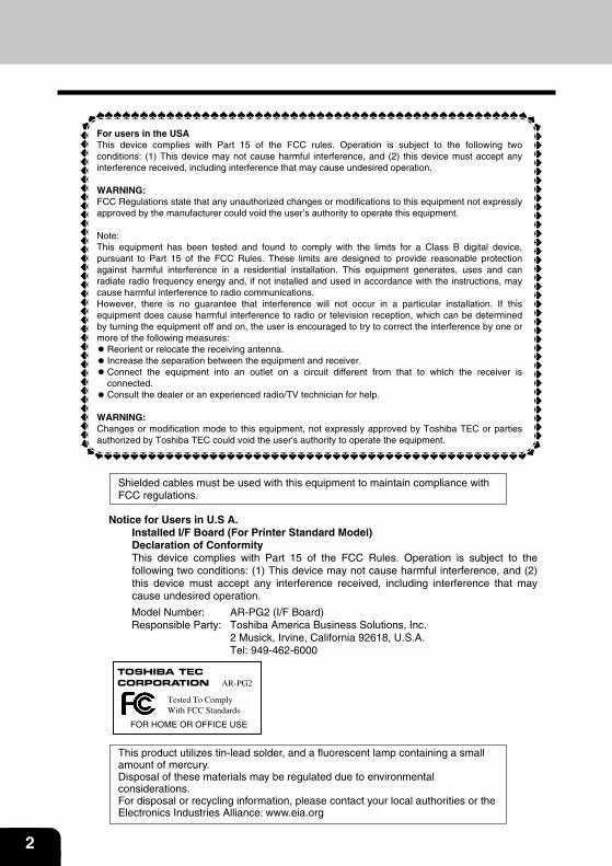
CAUTIONVORSICHTADVARSEL
ADVERSELVARNINGVARO!
INVISIBLE LASER RADIATION WHEN OPEN AND INTERLOCKS DEFEATED.AVOID EXPOSURE TO BEAM.
UNSICHTBARE LASERSTRAHLUNG WENN ABDECKUNG GEÖFFNET UNDSICHERHEITSVERRIEGELUNG ÜBERERÜCKT. NICHT DEM STRAHL AUSSETZEN.USYNLIG LASERSTRÅLING VED ÅBNING, NÅR SIKKERHEDSAFBRYDERE ER UDE AF FUNKTION. UNDGA UDSAETTELSE FOR STRÅLING.
USYNLIG LASERSTRÅLING NÅR DEKSEL ÅPNES OG SIKKERHEDSLÅS BRYTES. UNNGÅ EKSPONERING FOR STRÅLEN.
OSYNLIG LASERSTRÅLNING NÄR DENNA DEL ÄR ÖPPNAD OCH SPÄRRAR ÄR URKOPPLADE. STRÅLEN ÄR FARLIG. BETRAKTA EJ STRÅLEN.
AVATTAESSA JA SUOJALUKITUS OHITETTAESSA OLET ALTTIINA NÄKYMÄTÖNTÄLASERSÄTEILYLLE. ÄLÄ KATSO SÄTEESEEN.
Laserstrahl
CLASS 1 LASER PRODUCT
LASER KLASSE 1
LUOKAN 1 LASERLAITE
KLASS 1 LASERAPPARAT
VAROITUS!LAITTEEN KÄYTTÄMINEN MUULLA KUIN TÄSSÄ KÄYTTÖOHJEESSA MAINITULLA TAVALLA SAATTAA ALTISTAA KÄYTTÄJÄN TURVALLISUUSLUOKAN 1 YLITTÄVÄLLE NÄKYMÄTTÖMÄLLE LASERSÄTEILYLLE.
VARNINGOM APPARATEN ANVÄNDS PÅ ANNAT SÄTT ÄN I DENNA BRUKSANVISNING SPECIFICERATS, KAN ANVÄNDAREN UTSÄTTAS FÖR OSYNLIG LASERSTRÅLNING, SOM ÖVERSKRIDER GRÄNSEN FÖR LASERKLASS 1.
CLASS 1LASER PRODUCT
LASER KLASSE 1
CautionThis product contains a low power laser device.To ensure continued safety do not remove any cover or attempt to gain access to the inside of the product. Refer all servicing to qualified personnel.
5
The CE mark logo label is affixed on an equipment in case that the directives described in the abovesentence are applicable to the product. (This sentence is not applicable in any country where the abovedirectives are not required.)
In some areas, the “POWER” switch positions are marked “I ” and “O” on the copier instead of“ON” and “OFF”. The symbol “O” denotes the copier is not completely de-energized but in astand-by condition at this “POWER” switch position.
If your copier is so marked, please read “I ” for “ON” and “O” for “OFF”.
Caution!
For a complete electrical disconnection, pull out the main plug. The socket-outlet shall beinstalled near the equipment and shall be easily accessible.
6
CAUTIONS
Caution label on the unit
The label in the fusing area of the unit indicates the following:
: Caution, risk of danger
: Caution, hot surface
Cautions on using
Follow the cautions below when using this unit.
Warning:
• The fusing area is hot. Exercise care in this area when removing misfed paper.• Do not look directly at the light source. Doing so may damage your eyes.• Do not switch the unit rapidly on and off. After turning the unit off, wait 10 to 15 seconds
before turning it back on.• Unit power must be turned off before installing any supplies.
Caution:
• Place the unit on a firm, level surface.• Do not install the unit in a humid or dusty location.• When the unit is not used for a long time, for example for consecutive holidays, turn the
power switch off and remove the power cord from the outlet.• When moving the unit, be sure to turn the power switch off and remove the power cord
from the outlet.• Do not cover the unit with a dust cover, cloth or plastic film while the power is on. Doing
so may prevent heat radiation, damaging the unit.• Use of controls or adjustments or performance of procedures other than those specified
herein may result in hazardous radiation exposure.• The socket outlet should be installed near the equipment and be easily accessible.• The power plug should be unplugged from the outlet once a year or more often to clean
the area between its edges.If dust collects in the power plug area, humidity or the like may cause the insulation todeteriorate and a fire may well result.
• Do not throw toner or toner cartridge into fire. Toner may scatter and cause a burn.
Important points when selecting an installation site
Do not install your unit in areas that are:
• damp, humid, or very dusty• exposed to direct sunlight• poorly ventilated• subject to extreme temperature or humidity changes, e.g., near an air conditioner or
heater.
7
Be sure to connect the power cord only to a power outlet that meets the specified voltage and currentrequirements. Also make certain the outlet is properly grounded.-
Connect the unit to a power outlet which is not used for other electric appliances. If a lightingfixture is connected to the same outlet, the light may flicker.
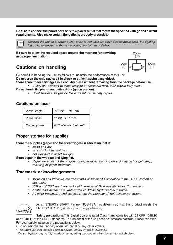
Be sure to allow the required space around the machine for servicingand proper ventilation.
Cautions on handling
Be careful in handling the unit as follows to maintain the performance of this unit.Do not drop the unit, subject it to shock or strike it against any object.Store spare toner cartridges in a cool dry place without removing from the package before use.
• If they are exposed to direct sunlight or excessive heat, poor copies may result.Do not touch the photoconductive drum (green portion).
• Scratches or smudges on the drum will cause dirty copies.
Cautions on laser
Wave length 770 nm – 795 nm
Pulse times 11.82 µs / 7 mm
Output power 0.17 mW +/- 0.01 mW
Proper storage for supplies
Store the supplies (paper and toner cartridges) in a location that is:• clean and dry• at a stable temperature• not exposed to direct sunlight.
Store paper in the wrapper and lying flat.• Paper stored out of the wrapper or in packages standing on end may curl or get damp,
resulting in paper misfeeds.
Trademark acknowledgements
• Microsoft and Windows are trademarks of Microsoft Corporation in the U.S.A. and othercountries.
• IBM and PC/AT are trademarks of International Business Machines Corporation.• Adobe and Acrobat are trademarks of Adobe Systems Incorporated.• All other trademarks and copyrights are the property of their respective owners.
As an ENERGY STAR® Partner, TOSHIBA has determined that this product meets theENERGY STAR® guidelines for energy efficiency.
Safety precautions:This Digital Copier is rated Class 1 and complies with 21 CFR 1040.10and 1040.11 of the CDRH standards. This means that the unit does not produce hazardous laser radiation.For your safety, observe the precautions below.• Do not remove the cabinet, operation panel or any other covers.• The unit’s exterior covers contain several safety interlock switches. Do not bypass any safety interlock by inserting wedges or other items into switch slots.
20cm (8")
10cm(4")
10cm(4")
8
CONTENTS
INTRODUCTION..................................................................................................... 1-1USING THE MANUAL ............................................................................................. 1-2
PART NAMES .......................................................................................................... 1-3
OPERATION PANEL ............................................................................................... 1-4
LOADING PAPER ................................................................................................... 2-1PAPER ..................................................................................................................... 2-2
LOADING THE PAPER TRAY ................................................................................. 2-4
BYPASS FEED (including special paper) ................................................................ 2-6
MAKING COPIES ................................................................................................... 3-1COPY FLOW ........................................................................................................... 3-2
CONNECTING THE POWER CORD ..................................................................... 3-3
ORIGINAL PLACEMENT ........................................................................................ 3-5
SET THE COPY QUANTITY ................................................................................... 3-6
EXPOSURE ADJUSTMENT/PHOTO COPYING ................................................... 3-6
REDUCTION/ENLARGEMENT/ZOOM .................................................................. 3-8
SELECTING THE TRAY .......................................................................................... 3-9
SPECIAL FUNCTIONS........................................................................................... 4-1DESCRIPTION OF SPECIAL FUNCTIONS........................................................... 4-2
TONER SAVE MODE .............................................................................................. 4-2
USER PROGRAMS ................................................................................................ 4-3
DISPLAYING TOTAL NUMBER OF COPIES.......................................................... 4-4
MAINTENANCE ...................................................................................................... 5-1TONER CARTRIDGE REPLACEMENT .................................................................5-2
CLEANING THE UNIT............................................................................................. 5-5
TROUBLESHOOTING THE UNIT .......................................................................... 6-1TROUBLESHOOTING ............................................................................................ 6-2
STATUS INDICATORS............................................................................................. 6-3
MISFEED REMOVAL .............................................................................................. 6-4
DEVELOPER REQUIRED ...................................................................................... 6-7
MAINTENANCE REQUIRED .................................................................................. 6-7
9
INSTALLING THE SOFTWARE ............................................................................. 7-1SOFTWARE FOR THE TOSHIBA PERSONAL MFP SERIES............................... 7-2
HARDWARE AND SOFTWARE REQUIREMENTS ............................................... 7-3
BEFORE INSTALLATION ........................................................................................ 7-3
INSTALLING THE SOFTWARE............................................................................... 7-5
INDICATORS ON THE OPERATION PANEL ....................................................... 7-15
USING THE PRINTER MODE .............................................................................. 7-16
USING THE SCANNER MODE ............................................................................ 7-18
HOW TO USE THE ONLINE MANUAL ................................................................. 7-26
USING OTHER INSTALLED DRIVERS ................................................................ 7-28
CONNECTING THE INTERFACE CABLE ........................................................... 7-29
APPENDIX .............................................................................................................. 8-1SPECIFICATIONS ................................................................................................... 8-2
OPTIONAL EQUIPMENT........................................................................................ 8-4
INDEX ...................................................................................................................... 8-9
SOFTWARE LICENSE .......................................................................................... 8-11

10
1-1
INTRODUCTION
This chapter provides basic information for using the unit.
USING THE MANUAL . . . . . . . . . . . . . . . . . . . . . . . . . . . . . . . . . . . . . . . . . . 1-2
PART NAMES . . . . . . . . . . . . . . . . . . . . . . . . . . . . . . . . . . . . . . . . . . . . . . . . 1-3
OPERATION PANEL . . . . . . . . . . . . . . . . . . . . . . . . . . . . . . . . . . . . . . . . . . . 1-4
1-2 INTRODUCTION
USING THE MANUALThe operator’s manual contains explanations of how to operate the unit, important considerations, andmaintenance procedures. To get the most out of the unit, please read the operator’s manual. Please keepthe operator’s manuals in a suitable location that will allow for convenient future reference.
Conventions used in this manual
In this manual, the following icons are used to provide the user with information pertinent to the use of theunit.
Warns the user that injury to the user or damage to the copier may result if the contentsof the warning are not properly followed.
Cautions the user that damage to the copier or one of its components may result if thecontents of the caution are not properly followed.
Notes provide information relevant to the copier regarding specifications, functions,performance, operation and such, that may be useful to the user.
Indicates a letter displayed in the display.
AB series (metric) and inch series references
When references are made to paper sizes and weights, the inch series values are quoted in brackets.For example:52 to 130 g/m2 (14 lbs. to 34.5 lbs.)A4 (8-1/2" x 11")
1-3
2
3
4
1
5
7
8
6910
11
12
13
Toner cartridge
Photoconductive drum
3
14
15
16
5
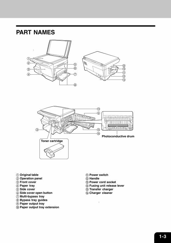
� Original table� Operation panel� Front cover� Paper tray� Side cover� Side cover open button� Multi-bypass tray� Bypass tray guides Paper output tray Paper output tray extension
� Power switch� Handle Power cord socket� Fusing unit release lever� Transfer charger� Charger cleaner
PART NAMES
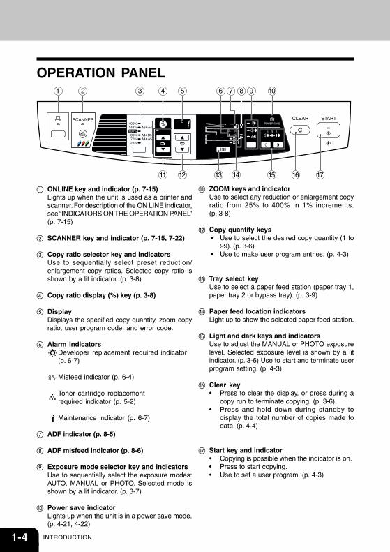
1-4 INTRODUCTION
OPERATION PANEL1 3 94 5 6 7 8 10
11 12 1513 16 1714
2
� ZOOM keys and indicator Use to select any reduction or enlargement copy
ratio from 25% to 400% in 1% increments.(p. 3-8)
� Copy quantity keys • Use to select the desired copy quantity (1 to
99). (p. 3-6) • Use to make user program entries. (p. 4-3)
Tray select key Use to select a paper feed station (paper tray 1,
paper tray 2 or bypass tray). (p. 3-9)
� Paper feed location indicators Light up to show the selected paper feed station.
� Light and dark keys and indicators Use to adjust the MANUAL or PHOTO exposure
level. Selected exposure level is shown by a litindicator. (p. 3-6) Use to start and terminate userprogram setting. (p. 4-3)
� Clear key• Press to clear the display, or press during a
copy run to terminate copying. (p. 3-6) • Press and hold down during standby to
display the total number of copies made todate. (p. 4-4)
� Start key and indicator • Copying is possible when the indicator is on.
• Press to start copying. • Use to set a user program. (p. 4-3)
� ONLINE key and indicator (p. 7-15) Lights up when the unit is used as a printer and
scanner. For description of the ON LINE indicator,see “INDICATORS ON THE OPERATION PANEL”(p. 7-15)
� SCANNER key and indicator (p. 7-15, 7-22)
� Copy ratio selector key and indicators Use to sequentially select preset reduction/
enlargement copy ratios. Selected copy ratio isshown by a lit indicator. (p. 3-8)
� Copy ratio display (%) key (p. 3-8)
� Display Displays the specified copy quantity, zoom copy
ratio, user program code, and error code.
� Alarm indicators Developer replacement required indicator
(p. 6-7)
Misfeed indicator (p. 6-4)
Toner cartridge replacementrequired indicator (p. 5-2)
Maintenance indicator (p. 6-7)
� ADF indicator (p. 8-5)
� ADF misfeed indicator (p. 8-6)
Exposure mode selector key and indicators Use to sequentially select the exposure modes:
AUTO, MANUAL or PHOTO. Selected mode isshown by a lit indicator. (p. 3-7)
Power save indicator Lights up when the unit is in a power save mode.
(p. 4-21, 4-22)
2-1
LOADING PAPER
Follow the steps below to load paper into the tray.
PAPER . . . . . . . . . . . . . . . . . . . . . . . . . . . . . . . . . . . . . . . . . . . . . . . . . . . . . 2-2
LOADING THE PAPER TRAY . . . . . . . . . . . . . . . . . . . . . . . . . . . . . . . . . . . 2-4
BYPASS FEED (including special paper) . . . . . . . . . . . . . . . . . . . . . . . . . 2-6
2-2 LOADING PAPER
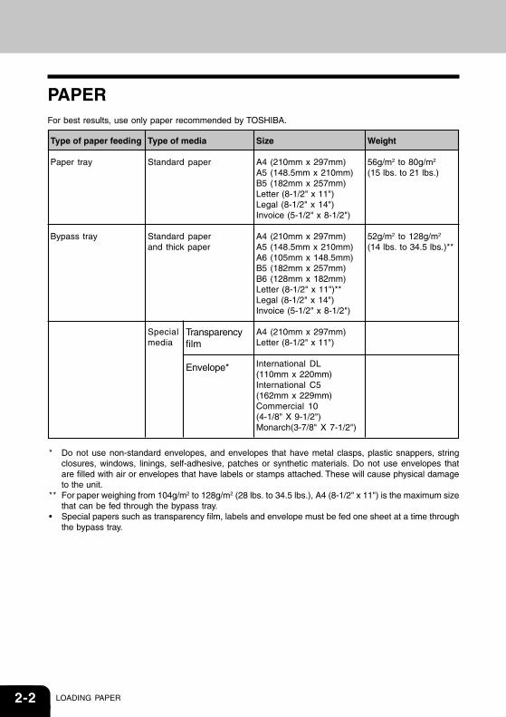
Type of paper feeding
Paper tray
Bypass tray
Type of media
Standard paper
Standard paperand thick paper
Specialmedia
Size
A4 (210mm x 297mm)A5 (148.5mm x 210mm)B5 (182mm x 257mm)Letter (8-1/2" x 11")Legal (8-1/2" x 14")Invoice (5-1/2" x 8-1/2")
A4 (210mm x 297mm)A5 (148.5mm x 210mm)A6 (105mm x 148.5mm)B5 (182mm x 257mm)B6 (128mm x 182mm)Letter (8-1/2" x 11")**Legal (8-1/2" x 14")Invoice (5-1/2" x 8-1/2")
A4 (210mm x 297mm)Letter (8-1/2" x 11")
International DL(110mm x 220mm)International C5(162mm x 229mm)Commercial 10(4-1/8" X 9-1/2")Monarch(3-7/8" X 7-1/2")
Weight
56g/m2 to 80g/m2
(15 lbs. to 21 lbs.)
52g/m2 to 128g/m2
(14 lbs. to 34.5 lbs.)**
* Do not use non-standard envelopes, and envelopes that have metal clasps, plastic snappers, stringclosures, windows, linings, self-adhesive, patches or synthetic materials. Do not use envelopes thatare filled with air or envelopes that have labels or stamps attached. These will cause physical damageto the unit.
** For paper weighing from 104g/m2 to 128g/m2 (28 lbs. to 34.5 lbs.), A4 (8-1/2" x 11") is the maximum sizethat can be fed through the bypass tray.
• Special papers such as transparency film, labels and envelope must be fed one sheet at a time throughthe bypass tray.
PAPERFor best results, use only paper recommended by TOSHIBA.
Transparencyfilm
Envelope*
2-3
Be sure to use only genuine TOSHIBA parts and supplies. For best copying results, be sureto use only TOSHIBA Genuine Supplies which are designed, engineered, and tested tomaximize the life and performance of TOSHIBA copiers. Look for the Genuine Supplies labelon the toner package.
Proper storage
1. Store the supplies in a location that is:• clean and dry,• at a stable temperature,• not exposed to direct sunlight.
2. Store copy paper in the wrapper and lying flat.• Paper stored out of the wrapper or in packages standing on end may curl or get damp,
resulting in paper misfeeds.
2-4 LOADING PAPER
LOADING THE PAPER TRAY
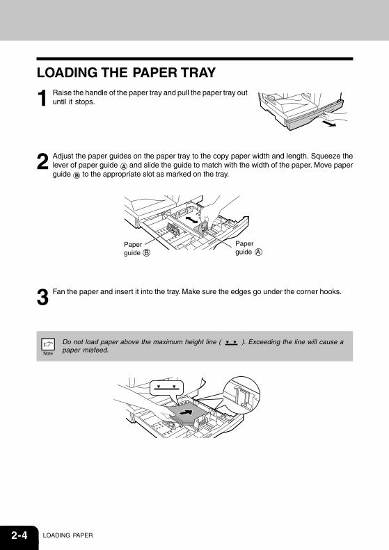
1 Raise the handle of the paper tray and pull the paper tray outuntil it stops.
2 Adjust the paper guides on the paper tray to the copy paper width and length. Squeeze thelever of paper guide A and slide the guide to match with the width of the paper. Move paperguide B to the appropriate slot as marked on the tray.
3 Fan the paper and insert it into the tray. Make sure the edges go under the corner hooks.
Do not load paper above the maximum height line ( ). Exceeding the line will cause apaper misfeed.
Paper guide B
Paper guide A
2-5
4 Gently push the paper tray back into the unit.
• After loading paper, to cancel the blinking without restarting copying, press the clear
( ) key. The in the display will go out and the start ( ) indicator will light up.• Be sure that paper is free of rips, dust, wrinkles, and curled or bent edges.• Make sure all the paper in the stack is the same size and type.• When loading paper, ensure there is no space between the paper and the guide, and
check if the guide is not set too narrow causing the paper to bend. Loading paper inthese ways will result in document skew or a paper jam.
• When not using the unit for an extended period, remove all paper from the paper tray andstore it in a dry place. If paper is left in the unit for an extended period, the paper willabsorb moisture from the air, resulting in paper jams.
• When adding new paper to the paper tray, remove the old paper already contained in thetray. Placing new paper on top of the paper already contained in the tray may result infeeding two sheets at one time.
2-6 LOADING PAPER
BYPASS FEED (including special paper)The bypass tray automatically feeds up to 50 sheets of standard copy paper and also feeds special paperssuch as transparency film and labels one sheet at a time. Copy paper measuring from A6 to A4 (3-1/2" x 5-1/2" to 8-1/2" x 14") and in the weight range of 52 to 128g/m2 (28 to 34.5 lbs.) can be used in this tray. (Forpaper weighing from 104 to 128g/m2 (28 to 34.5 Ibs.), A4 (8-1/2" X 11") is the maximum size.)
1 Place the original face down on the original table. Align it with the original scale and close theoriginal cover.
The original image must be smaller than the paper or media for copying.If the original image is bigger than the paper or media, this may cause smudges on theedges of the copies.
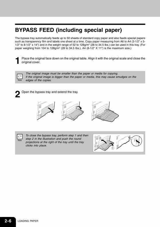
2 Open the bypass tray and extend the tray.
To close the bypass tray, perform step 1 and thenstep 2 in the illustration and push the roundprojections at the right of the tray until the trayclicks into place.

2-7
3 Set the paper guides to the copy paper width. Insert the copy paper (print face down) all theway into the bypass tray.
4 Press the tray select ( ) key to select the bypass tray. Set the number of copies if usingstandard copy paper. Press the start ( ) key.
Print face
• Paper must be fed narrow side into the feed slot.• Transparency film, labels, and other special purpose papers must be fed individually.• When copying onto transparency film, remove each copy promptly.
Do not let copies stack up.• When loading an envelope, make sure that it is straight and flat.

2-8 LOADING PAPER
3-1
Making CopiesThis chapter explains basic and other copying functions.The unit is equipped with a one-page memory buffer. This memory allows the unit to scan an original onceonly and make up to 99 copies. This feature improves workflow, reduces operation noise from the copier,and provides higher reliability by reducing wear and tear on the scanning mechanism.
If the unit does not function properly during use, or if a function cannot be used, see“TROUBLESHOOTING THE UNIT (p. 2-6)”
COPY FLOW ...........................................................................................................................3-2
CONNECTING THE POWER CORD .....................................................................................3-3
ORIGINAL PLACEMENT ........................................................................................................3-5
SET THE COPY QUANTITY ...................................................................................................3-6
EXPOSURE ADJUSTMENT/PHOTO COPYING ...................................................................3-6
REDUCTION/ENLARGEMENT/ZOOM ..................................................................................3-8
SELECTING THE TRAY ..........................................................................................................3-9
3-2 MAKING COPIES
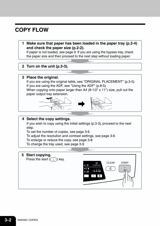
COPY FLOW
3-3
CONNECTING THE POWER CORD
If you use the unit in a country other than the country where the unit was purchased, you willneed to make sure that your local power supply is compatible with your model. If you plugthe unit into an incompatible power supply, irreparable damage to the unit will result.
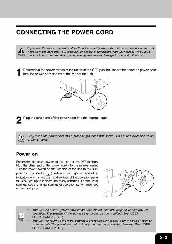
1 Ensure that the power switch of the unit is in the OFF position. Insert the attached power cordinto the power cord socket at the rear of the unit.
2 Plug the other end of the power cord into the nearest outlet.
Only insert the power cord into a properly grounded wall socket. Do not use extension cordsor power strips.
Power on
Ensure that the power switch of the unit is in the OFF position.Plug the other end of the power cord into the nearest outlet.Turn the power switch on the left side of the unit to the “ON”position. The start ( ) indicator will light up and otherindicators which show the initial settings of the operation panelwill also light up to indicate the ready condition. For the initialsettings, see the “Initial settings of operation panel” describedon the next page.
• The unit will enter a power save mode once the set time has elapsed without any unit
operation. The settings of the power save modes can be modified. See “USERPROGTRAMS” (p. 4-3)
• The unit will return to the initial settings a preset amount of time after the end of copy orscanning job. The preset amount of time (auto clear time) can be changed. See “USERPROGTRAMS” (p. 4-3)
3-4 MAKING COPIES
About the scan head
The scan head lamp remains on constantly when the unit is in the ready condition(when the start ( ) indicator is illuminated).The unit adjusts the scan head lamp periodically to maintain copying quality. At this time, the scan headmoves automatically. This is normal and does not indicate unit trouble.
Initial settings of operation panel
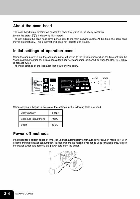
When the unit power is on, the operation panel will revert to the initial settings when the time set with the“Auto clear time” setting (p. 4-2) elapses after a copy or scanner job is finished, or when the clear ( ) keyis pressed twice.The initial settings of the operation panel are shown below.
When copying is begun in this state, the settings in the following table are used.
Copy quantity 1 copy
Exposure adjustment AUTO
Zoom 100%
Power off methods
If not used for a certain period of time, the unit will automatically enter auto power shut-off mode (p. 4-3) inorder to minimise power consumption. In cases where the machine will not be used for a long time, turn offthe power switch and remove the power cord from the outlet.
3-5
ORIGINAL PLACEMENT• The original table can read up to A4 (8-1/2" x 14") original.• Image loss 4mm (5/32") can occur at the leading and trailing edges of the copies. Also
image loss 4.5mm (11/64") in total can occur along the other edges of the copies.• When copying a book or an original which has been folded or a crumpled original,
press down the original cover lightly. If the original cover is not securely closed, thecopies may be striped or blurred.
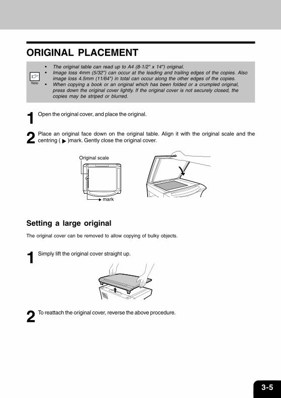
1 Open the original cover, and place the original.
2 Place an original face down on the original table. Align it with the original scale and thecentring ( )mark. Gently close the original cover.
Setting a large original
The original cover can be removed to allow copying of bulky objects.
1 Simply lift the original cover straight up.
2 To reattach the original cover, reverse the above procedure.
mark
Original scale
3-6 MAKING COPIES
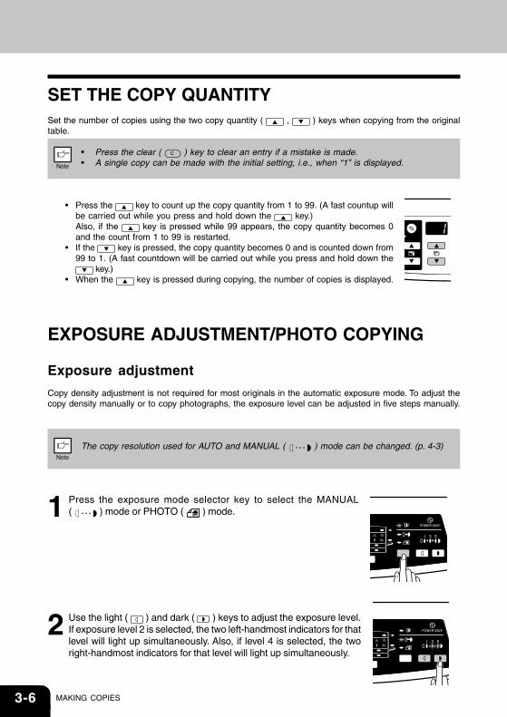
SET THE COPY QUANTITYSet the number of copies using the two copy quantity ( , ) keys when copying from the originaltable.
• Press the clear ( ) key to clear an entry if a mistake is made.• A single copy can be made with the initial setting, i.e., when “1” is displayed.
• Press the key to count up the copy quantity from 1 to 99. (A fast countup willbe carried out while you press and hold down the key.)Also, if the key is pressed while 99 appears, the copy quantity becomes 0and the count from 1 to 99 is restarted.
• If the key is pressed, the copy quantity becomes 0 and is counted down from99 to 1. (A fast countdown will be carried out while you press and hold down the
key.) • When the key is pressed during copying, the number of copies is displayed.
EXPOSURE ADJUSTMENT/PHOTO COPYING
Exposure adjustment
Copy density adjustment is not required for most originals in the automatic exposure mode. To adjust thecopy density manually or to copy photographs, the exposure level can be adjusted in five steps manually.
The copy resolution used for AUTO and MANUAL ( ) mode can be changed. (p. 4-3)
1 Press the exposure mode selector key to select the MANUAL( ) mode or PHOTO ( ) mode.
2 Use the light ( ) and dark ( ) keys to adjust the exposure level.If exposure level 2 is selected, the two left-handmost indicators for thatlevel will light up simultaneously. Also, if level 4 is selected, the tworight-handmost indicators for that level will light up simultaneously.
3-7
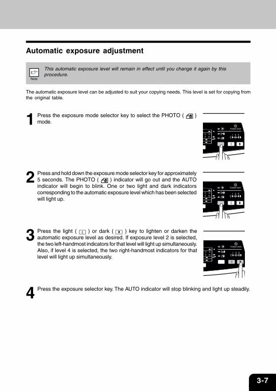
Automatic exposure adjustment
This automatic exposure level will remain in effect until you change it again by thisprocedure.
The automatic exposure level can be adjusted to suit your copying needs. This level is set for copying fromthe original table.
1 Press the exposure mode selector key to select the PHOTO ( )mode.
2 Press and hold down the exposure mode selector key for approximately5 seconds. The PHOTO ( ) indicator will go out and the AUTOindicator will begin to blink. One or two light and dark indicatorscorresponding to the automatic exposure level which has been selectedwill light up.
3 Press the light ( ) or dark ( ) key to lighten or darken theautomatic exposure level as desired. If exposure level 2 is selected,the two left-handmost indicators for that level will light up simultaneously.Also, if level 4 is selected, the two right-handmost indicators for thatlevel will light up simultaneously.
4 Press the exposure selector key. The AUTO indicator will stop blinking and light up steadily.
3-8 MAKING COPIES
REDUCTION/ENLARGEMENT/ZOOMThree preset reduction ratios and two enlargement ratios can be selected. The zoom function enablescopy ratio selection from 25% to 400% in 1% increments.
1 Set the original and check the paper size.
2 Use the copy ratio selector key and/or ZOOM ( , ) keys to select the desired copyratio.
• To verify a zoom setting without changing the zoom ratio, press and hold down the copyratio display key. When the key is released, the display will return to the copy quantitydisplay.
• To reset the ratio to 100%, press the copy ratio selector key repeatedly until the 100%indicator lights up.
3 Set the reduction/enlargement ratio.
To decrease or increase the zoom ratio rapidly, press and hold down the ZOOM ( ) or( ) key. However the value will stop at the preset reduction or enlargement ratios. Tomove beyond these ratios, release the key and then press and hold it down again.
To select a preset copy ratio:
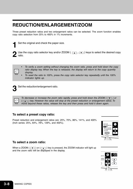
Preset reduction and enlargement ratios are: 25%, 70%, 86%, 141%, and 400%(Inch series: 25%, 64%, 78%, 129%, and 400%).
To select a zoom ratio:
When a ZOOM ( ) or ( ) key is pressed, the ZOOM indicator will light upand the zoom ratio will be displayed in the display.
3-9
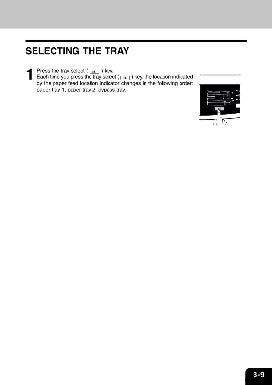
SELECTING THE TRAY
1 Press the tray select ( ) key.Each time you press the tray select ( ) key, the location indicatedby the paper feed location indicator changes in the following order:paper tray 1, paper tray 2, bypass tray.

3-10 MAKING COPIES
4-1
Special FunctionsThis chapter describes the special functions of this unit. Use these functions as needed.
DESCRIPTION OF SPECIAL FUNCTIONS ...........................................................................4-2
TONER SAVE MODE..............................................................................................................4-2
USER PROGRAMS ................................................................................................................4-3
DISPLAYING TOTAL NUMBER OF COPIES .........................................................................4-4

4-2 SPECIAL FUNCTIONS
DESCRIPTION OF SPECIAL FUNCTIONS
Toner save mode (p. 4-2)
Reduces toner consumption by approximately 10%.
Power save modes (p. 4-3)
The unit has two power save modes of operation: preheat mode and auto power shut-off mode.
Preheat mode
When the unit enters the preheat mode, the power save ( ) indicator will light up and otherindicators will remain on or off as before. In this condition, the fuser in the unit is maintained at alower heat level, thereby saving power. To copy from the preheat mode, make desired copierselections and press the start ( ) key using the normal copying procedure.
Auto power shut-off mode
When the unit enters the auto power shut-off mode, the power save ( ) indicator will light up andother indicators except the ONLINE indicator will go out. The auto power shut-off mode saves morepower than the preheat mode but requires a longer time before starting copying. To copy from theauto power shut-off mode, press the start ( ) key. Then make desired copier selections and
press the start ( ) key using the normal copying procedure.
Auto clear (p. 4-3)
The unit returns to the initial settings a preset amount of time after the end of copy, or scanner job. Thispreset amount of time (auto clear time) can be changed.
Resolution of AUTO & MANUAL mode (p. 4-3)
You can set the copy resolution used for AUTO and MANUAL ( ) exposure mode.
TONER SAVE MODE
1 Press the exposure mode selector key to select theMANUAL ( ) mode.
4-3
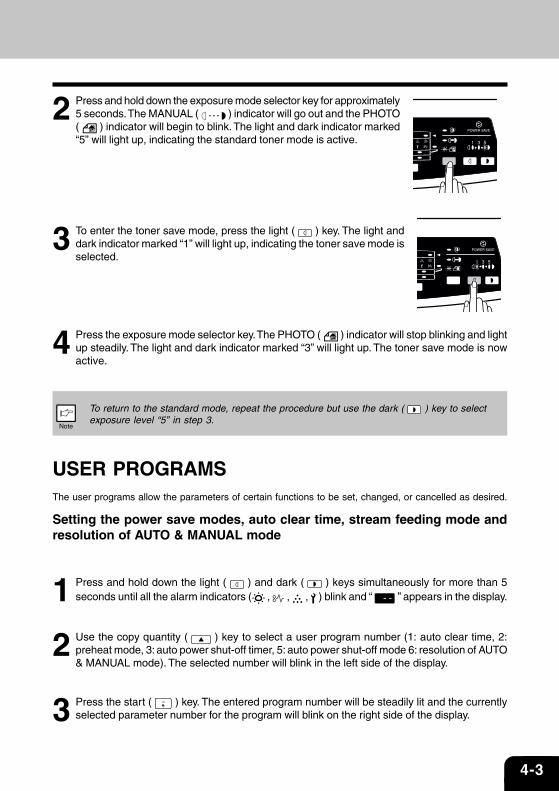
2 Press and hold down the exposure mode selector key for approximately5 seconds. The MANUAL ( ) indicator will go out and the PHOTO( ) indicator will begin to blink. The light and dark indicator marked“5” will light up, indicating the standard toner mode is active.
3 To enter the toner save mode, press the light ( ) key. The light anddark indicator marked “1” will light up, indicating the toner save mode isselected.
4 Press the exposure mode selector key. The PHOTO ( ) indicator will stop blinking and lightup steadily. The light and dark indicator marked “3” will light up. The toner save mode is nowactive.
To return to the standard mode, repeat the procedure but use the dark ( ) key to selectexposure level “5” in step 3.
USER PROGRAMSThe user programs allow the parameters of certain functions to be set, changed, or cancelled as desired.
Setting the power save modes, auto clear time, stream feeding mode andresolution of AUTO & MANUAL mode
1 Press and hold down the light ( ) and dark ( ) keys simultaneously for more than 5seconds until all the alarm indicators ( , , , ) blink and “ ” appears in the display.
2 Use the copy quantity ( ) key to select a user program number (1: auto clear time, 2:preheat mode, 3: auto power shut-off timer, 5: auto power shut-off mode 6: resolution of AUTO& MANUAL mode). The selected number will blink in the left side of the display.
3 Press the start ( ) key. The entered program number will be steadily lit and the currentlyselected parameter number for the program will blink on the right side of the display.
4-4 SPECIAL FUNCTIONS
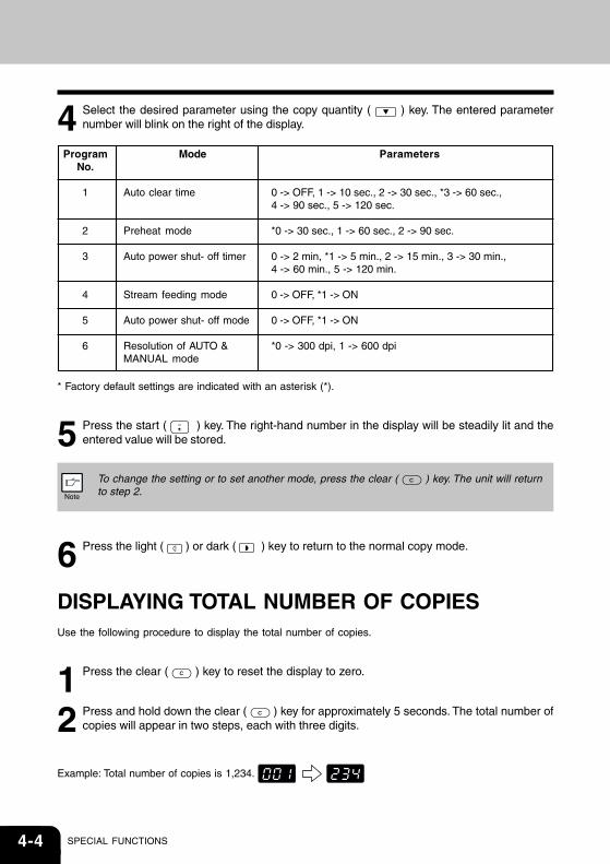
4 Select the desired parameter using the copy quantity ( ) key. The entered parameternumber will blink on the right of the display.
* Factory default settings are indicated with an asterisk (*).
5 Press the start ( ) key. The right-hand number in the display will be steadily lit and theentered value will be stored.
To change the setting or to set another mode, press the clear ( ) key. The unit will returnto step 2.
6 Press the light ( ) or dark ( ) key to return to the normal copy mode.
DISPLAYING TOTAL NUMBER OF COPIESUse the following procedure to display the total number of copies.
1 Press the clear ( ) key to reset the display to zero.
2 Press and hold down the clear ( ) key for approximately 5 seconds. The total number ofcopies will appear in two steps, each with three digits.
Example: Total number of copies is 1,234.
ProgramNo.
1
2
3
4
5
6
Mode
Auto clear time
Preheat mode
Auto power shut- off timer
Stream feeding mode
Auto power shut- off mode
Resolution of AUTO &MANUAL mode
Parameters
0 -> OFF, 1 -> 10 sec., 2 -> 30 sec., *3 -> 60 sec.,4 -> 90 sec., 5 -> 120 sec.
*0 -> 30 sec., 1 -> 60 sec., 2 -> 90 sec.
0 -> 2 min, *1 -> 5 min., 2 -> 15 min., 3 -> 30 min.,4 -> 60 min., 5 -> 120 min.
0 -> OFF, *1 -> ON
0 -> OFF, *1 -> ON
*0 -> 300 dpi, 1 -> 600 dpi
5-1
MaintenanceThis chapter describes how to replace the toner cartridge and how to clean the unit.
Be sure to use only genuine TOSHIBA parts and supplies.
For best copying results, be sure to use only TOSHIBA Genuine Supplies which aredesigned, engineered, and tested to maximise the life and performance of TOSHIBA copiers.Look for the Genuine Supplies label on the toner package.
TONER CARTRIDGE REPLACEMENT ................................................................................5-2
CLEANING THE UNIT ............................................................................................................5-5
5-2 MAINTENANCE
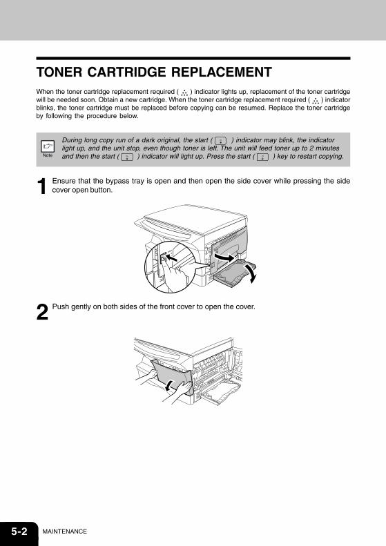
TONER CARTRIDGE REPLACEMENTWhen the toner cartridge replacement required ( ) indicator lights up, replacement of the toner cartridgewill be needed soon. Obtain a new cartridge. When the toner cartridge replacement required ( ) indicatorblinks, the toner cartridge must be replaced before copying can be resumed. Replace the toner cartridgeby following the procedure below.
During long copy run of a dark original, the start ( ) indicator may blink, the indicatorlight up, and the unit stop, even though toner is left. The unit will feed toner up to 2 minutesand then the start ( ) indicator will light up. Press the start ( ) key to restart copying.
1 Ensure that the bypass tray is open and then open the side cover while pressing the sidecover open button.
2 Push gently on both sides of the front cover to open the cover.
5-3
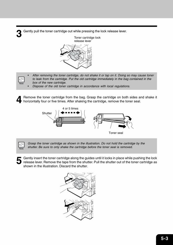
3 Gently pull the toner cartridge out while pressing the lock release lever.
• After removing the toner cartridge, do not shake it or tap on it. Doing so may cause tonerto leak from the cartridge. Put the old cartridge immediately in the bag contained in thebox of the new cartridge.
• Dispose of the old toner cartridge in accordance with local regulations.
4 Remove the toner cartridge from the bag. Grasp the cartridge on both sides and shake ithorizontally four or five times. After shaking the cartridge, remove the toner seal.
Grasp the toner cartridge as shown in the illustration. Do not hold the cartridge by theshutter. Be sure to only shake the cartridge before the toner seal is removed.
5 Gently insert the toner cartridge along the guides until it locks in place while pushing the lockrelease lever. Remove the tape from the shutter. Pull the shutter out of the toner cartridge asshown in the illustration. Discard the shutter.
Toner cartridge lock release lever
4 or 5 times
Shutter
Toner seal
5-4 MAINTENANCE
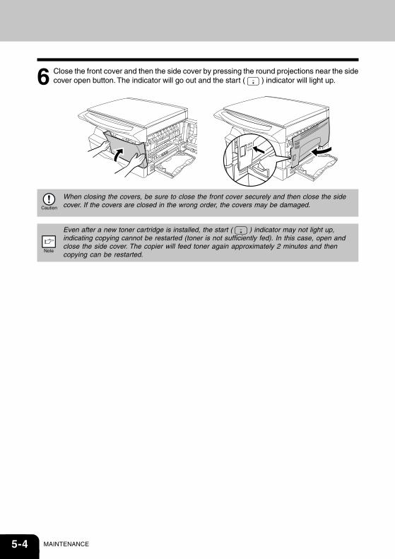
6 Close the front cover and then the side cover by pressing the round projections near the sidecover open button. The indicator will go out and the start ( ) indicator will light up.
When closing the covers, be sure to close the front cover securely and then close the sidecover. If the covers are closed in the wrong order, the covers may be damaged.
Even after a new toner cartridge is installed, the start ( ) indicator may not light up,indicating copying cannot be restarted (toner is not sufficiently fed). In this case, open andclose the side cover. The copier will feed toner again approximately 2 minutes and thencopying can be restarted.
5-5
CLEANING THE UNITProper care is essential in order to get clean, TOSHIBA copies. Be sure to take a few minutes to regularlyclean the unit.
• Before cleaning, be sure to turn the power switch off and remove the power cord from theoutlet.
• Do not use thinner, benzene or other volatile cleaning agents. Doing so may causedeformation, discoloration, deterioration or malfunction.
Cabinet
Wipe the cabinet with a soft, clean cloth.
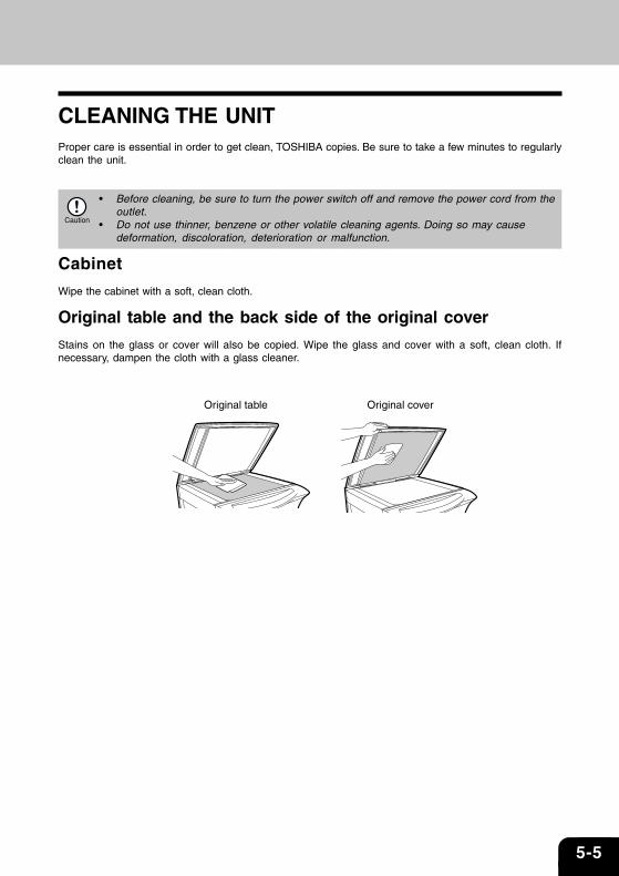
Original table and the back side of the original cover
Stains on the glass or cover will also be copied. Wipe the glass and cover with a soft, clean cloth. Ifnecessary, dampen the cloth with a glass cleaner.
Original table Original cover

5-6 MAINTENANCE
Transfer charger
If copies start becoming streaky or blotchy, the transfer charger may be dirty. Clean the charger using thefollowing procedure.
1 Turn the power switch off. (p.3-4)
2 Ensure that the bypass tray is open and then open the side cover while pressing the sidecover open button.
3 Take the charger cleaner out by holding the tab. Set the charger cleaner onto the right end ofthe transfer charger, gently slide the cleaner to the left end, and then remove it. Repeat thisoperation two or three times.
Slide the charger cleaner from the right end to the left end along the groove of the transfercharger. If the cleaner is stopped on the way, smudges on copies may occur.
4 Return the charger cleaner to its original position. Close the side cover by pressing the roundprojections near the side cover open button.
5 Turn the power switch on. (p.3-3)
6-1
TROUBLESHOOTING THEUNIT
This chapter describes misfeed removal and troubleshooting.
TROUBLESHOOTING ............................................................................................................6-2
STATUS INDICATORS ............................................................................................................6-3
MISFEED REMOVAL ..............................................................................................................6-4
DEVELOPER REQUIRED......................................................................................................6-7
MAINTENANCE REQUIRED .................................................................................................6-7
6-2 TROUBLESHOOTING
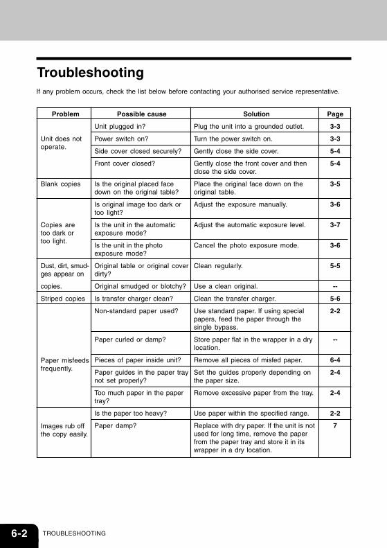
Troubleshooting
Problem
Unit does notoperate.
Blank copies
Copies aretoo dark ortoo light.
Dust, dirt, smud-ges appear on
copies.
Striped copies
Paper misfeedsfrequently.
Images rub offthe copy easily.
Possible cause
Unit plugged in?
Power switch on?
Side cover closed securely?
Front cover closed?
Is the original placed facedown on the original table?
Is original image too dark ortoo light?
Is the unit in the automaticexposure mode?
Is the unit in the photoexposure mode?
Original table or original coverdirty?
Original smudged or blotchy?
Is transfer charger clean?
Non-standard paper used?
Paper curled or damp?
Pieces of paper inside unit?
Paper guides in the paper traynot set properly?
Too much paper in the papertray?
Is the paper too heavy?
Paper damp?
Solution
Plug the unit into a grounded outlet.
Turn the power switch on.
Gently close the side cover.
Gently close the front cover and thenclose the side cover.
Place the original face down on theoriginal table.
Adjust the exposure manually.
Adjust the automatic exposure level.
Cancel the photo exposure mode.
Clean regularly.
Use a clean original.
Clean the transfer charger.
Use standard paper. If using specialpapers, feed the paper through thesingle bypass.
Store paper flat in the wrapper in a drylocation.
Remove all pieces of misfed paper.
Set the guides properly depending onthe paper size.
Remove excessive paper from the tray.
Use paper within the specified range.
Replace with dry paper. If the unit is notused for long time, remove the paperfrom the paper tray and store it in itswrapper in a dry location.
Page
3-3
3-3
5-4
5-4
3-5
3-6
3-7
3-6
5-5
--
5-6
2-2
--
6-4
2-4
2-4
2-2
7
If any problem occurs, check the list below before contacting your authorised service representative.
6-3
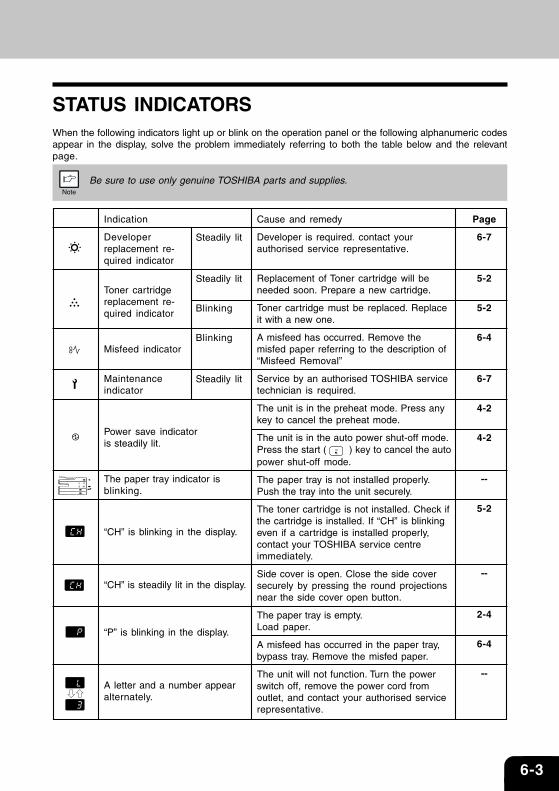
Indication
Developerreplacement re-quired indicator
Toner cartridgereplacement re-quired indicator
Misfeed indicator
Maintenanceindicator
Power save indicatoris steadily lit.
The paper tray indicator isblinking.
“CH” is blinking in the display.
“CH” is steadily lit in the display.
“P” is blinking in the display.
A letter and a number appearalternately.
STATUS INDICATORSWhen the following indicators light up or blink on the operation panel or the following alphanumeric codesappear in the display, solve the problem immediately referring to both the table below and the relevantpage.
Be sure to use only genuine TOSHIBA parts and supplies.
Steadily lit
Steadily lit
Blinking
Blinking
Steadily lit
Cause and remedy
Developer is required. contact yourauthorised service representative.
Replacement of Toner cartridge will beneeded soon. Prepare a new cartridge.
Toner cartridge must be replaced. Replaceit with a new one.
A misfeed has occurred. Remove themisfed paper referring to the description of“Misfeed Removal”
Service by an authorised TOSHIBA servicetechnician is required.
The unit is in the preheat mode. Press anykey to cancel the preheat mode.
The unit is in the auto power shut-off mode.Press the start ( ) key to cancel the autopower shut-off mode.
The paper tray is not installed properly.Push the tray into the unit securely.
The toner cartridge is not installed. Check ifthe cartridge is installed. If “CH” is blinkingeven if a cartridge is installed properly,contact your TOSHIBA service centreimmediately.
Side cover is open. Close the side coversecurely by pressing the round projectionsnear the side cover open button.
The paper tray is empty.Load paper.
A misfeed has occurred in the paper tray,bypass tray. Remove the misfed paper.
The unit will not function. Turn the powerswitch off, remove the power cord fromoutlet, and contact your authorised servicerepresentative.
Page
6-7
5-2
5-2
6-4
6-7
4-2
4-2
--
5-2
--
2-4
6-4
--
6-4 TROUBLESHOOTING
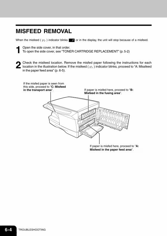
If paper is misfed here, proceed to "A: Misfeed in the paper feed area". (p.32)
If paper is misfed here, proceed to "B: Misfeed in the fusing area". (p.32)
If the misfed paper is seen from this side, proceed to "C: Misfeed in the transport area". (p.33)
MISFEED REMOVALWhen the misfeed ( ) indicator blinks or in the display, the unit will stop because of a misfeed.
1 Open the side cover, in that order.To open the side cover, see “TONER CARTRIDGE REPLACEMENT” (p. 5-2)
2 Check the misfeed location. Remove the misfed paper following the instructions for eachlocation in the illustration below. If the misfeed ( ) indicator blinks, proceed to “A: Missfeedin the paper feed area” (p. 6-5).
6-5
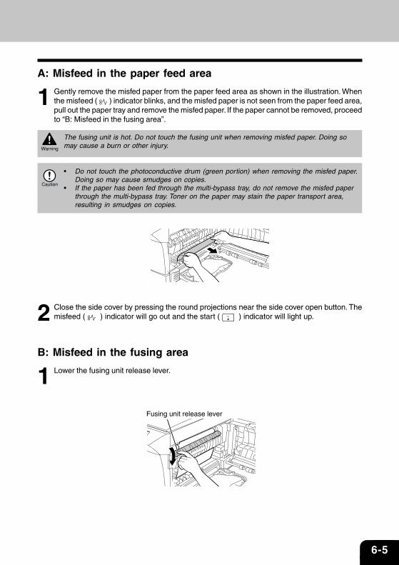
A: Misfeed in the paper feed area
1 Gently remove the misfed paper from the paper feed area as shown in the illustration. Whenthe misfeed ( ) indicator blinks, and the misfed paper is not seen from the paper feed area,pull out the paper tray and remove the misfed paper. If the paper cannot be removed, proceedto “B: Misfeed in the fusing area”.
The fusing unit is hot. Do not touch the fusing unit when removing misfed paper. Doing somay cause a burn or other injury.
• Do not touch the photoconductive drum (green portion) when removing the misfed paper.Doing so may cause smudges on copies.
• If the paper has been fed through the multi-bypass tray, do not remove the misfed paperthrough the multi-bypass tray. Toner on the paper may stain the paper transport area,resulting in smudges on copies.
2 Close the side cover by pressing the round projections near the side cover open button. Themisfeed ( ) indicator will go out and the start ( ) indicator will light up.
B: Misfeed in the fusing area
1 Lower the fusing unit release lever.
Fusing unit release lever
6-6 TROUBLESHOOTING
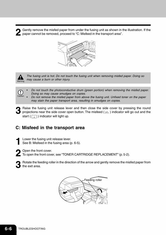
2 Gently remove the misfed paper from under the fusing unit as shown in the illustration. If thepaper cannot be removed, proceed to “C: Misfeed in the transport area”.
The fusing unit is hot. Do not touch the fusing unit when removing misfed paper. Doing somay cause a burn or other injury.
• Do not touch the photoconductive drum (green portion) when removing the misfed paper.Doing so may cause smudges on copies.
• Do not remove the misfed paper from above the fusing unit. Unfixed toner on the papermay stain the paper transport area, resulting in smudges on copies.
3 Raise the fusing unit release lever and then close the side cover by pressing the roundprojections near the side cover open button. The misfeed ( ) indicator will go out and thestart ( ) indicator will light up.
C: Misfeed in the transport area
1 Lower the fusing unit release lever.See B: Misfeed in the fusing area (p. 6-5).
2 Open the front cover.To open the front cover, see “TONER CARTRIDGE REPLACEMENT” (p. 5-2).
3 Rotate the feeding roller in the direction of the arrow and gently remove the misfed paper fromthe exit area.
Feeding roller
6-7
4 Raise the fusing unit release lever, close the front cover and then close the side cover bypressing the round projections near the side cover open button. The misfeed ( ) indicatorwill go out and the start ( ) indicator will light up.
When closing the covers, be sure to close the front cover securely and then close the sidecover. If the covers are closed in the wrong order, the covers may be damaged.
DEVELOPER REQUIREDWhen the developer replacement required ( ) indicator lights up, the developer should be replaced.DEVELOPER REPLACEMENT SHOULD ONLY BE DONE BY AN AUTORIZED TOSHIBA SERVICETECHNICIAN. Contact your service centre as soon as possible.
MAINTENANCE REQUIREDWhen maintenance ( ) indicator lights up, service by an authorised TOSHIBA service technician isrequired. Contact your service centre as soon as possible.

6-8 TROUBLESHOOTING
7-1
Installing the SoftwareThis chapter explains how to install the software that allows the e-STUDIO120, and e-STUDIO150 to beused as a printer and scanner, and the procedures for using the printer and scanner functions. Thefollowing term is used in this chapter.CD-ROM Means the supplied CD-ROM with the e-STUDIO120/150 series software.
SOFTWARE FOR THE TOSHIBA PERSONAL MFP SERIES ...............................................7-2
HARDWARE AND SOFTWARE REQUIREMENTS ...............................................................7-3
BEFORE INSTALLATION .......................................................................................................7-3
INSTALLING THE SOFTWARE...............................................................................................7-5
INDICATORS ON THE OPERATION PANEL ...................................................................... 7-15
USING THE PRINTER MODE ............................................................................................. 7-16
USING THE SCANNER MODE ........................................................................................... 7-18
HOW TO USE THE ONLINE MANUAL ................................................................................ 7-26
USING OTHER INSTALLED DRIVERS .............................................................................. 7-28
CONNECTING THE INTERFACE CABLE .......................................................................... 7-29
7-2 INSTALL THE SOFTWARE
SOFTWARE FOR THE TOSHIBA PERSONAL MFPSERIESThe supplied CD-ROM includes software for this unit.
MFP driverScanner driverPermits you to operate scanning function of this unit with TWAIN-compliant and WIA-compliant application.Printer driverEnables you to use the printer function of this unit with your computer.
Print Status WindowThe print state and information on current printing are displayed on the status monitor window.
Desktop Document ManagerAn integrated software environment that makes it easy to manage document and image files and launchapplications.
Button ManagerButton Manager enabling the SCANNER ( ) key located on the unit.
The scanning feature is only available with Windows 98/Me/2000/XP using a USBconnection. For users running Windows 95/NT 4.0 or using a parallel connection, onlyprinting is available.
7-3
IBM PC/AT or compatible computer equipped with a USB1.1*1 or bi-directional parallel interface (IEEE 1284)
Windows 95, Windows 98, Windows Me, Windows NT Workstation 4.0(ServicePack 5 or later)*3, Windows 2000 Professional*3, Windows XPProfessional*3, Windows XP Home Edition*3
800 x 600dots (SVGA) display with 256 colors (or better)
150MB or more
An environment on which any of the operating systems listed above canfully operate
HARDWARE AND SOFTWARE REQUIREMENTSCheck the following hardware and software requirements in order to install the software.
Computer type
Operating system*2
Display
Hard disk free space
Other requirementforhardware
*1Compatible with Windows 98, Windows Me, Windows 2000 Professional, Windows XP Professional orWindows XP Home Edition preinstalled model with USB interface equipped as standard.
*2Printing is unavailable in MS-DOS mode.*3The administrator’s authorisation is required to install this software using this installer.
BEFORE INSTALLATIONThe following table shows the drivers and software that can be installed for each version of Windows andinterface connection method.
*1When the unit is connected through the parallel port, the Print Status Window can only be used when theparallel port is set to ECP mode. To set the parallel port mode, refer to your computer manual or ask themanufacturer of your computer.
*2Desktop Document Manager can be installed when using a parallel interface connection, however, theunit’s scanner function cannot be used.
Is there another GDI printer driver or a Windows Printing System printer driver alreadyinstalled? If installed, change the printer port setting. For the change of the printer portsetting, see USING OTHER INSTALLED DRIVERS.(p. 7-28)
Users of Windows 98/Me/2000/XP whowill use the USB interface connection
Users of Windows 98/Me/2000/XP whowill use the parallel interface connection
Windows 95/NT 4.0 users
DesktopDocumentManager
Available
Available *2
ButtonManager
Available
Not Available
Scannerdriver
Available
Not Available
MFP Driver
Printer driver/Print Status
Window
Available *1
7-4 INSTALL THE SOFTWARE
Flow of installation
Refer to the following table and then begin installation.
Reference pages for how to install
Installing onto Windows XP (USB/parallel interface) (p. 7-5)
Installing onto Windows 98/Me/2000 (USB interface) (p. 7-9)
Installing onto Windows 95/98/Me/NT4.0/2000 (Parallelinterface) (p. 7-9)
Installing onto Windows 98/Me/2000 (USB interface) (p. 7-9)
Installing onto Windows 95/98/Me/NT4.0/2000 (Parallelinterface) (p. 7-9)
Installing onto Windows 98/Me/2000 (USB interface) (p. 7-9)
Installing onto Windows 95/98/Me/NT4.0/2000 (Parallelinterface) (p. 7-9)
Installing onto Windows 95/98/Me/NT4.0/2000 (Parallelinterface) (p. 7-9)
Operatingsystem
Windows XP
Windows 98
Windows Me
Windows 2000
Windows 95 / NT 4.0
Interface
USB/Parallel
USB
Parallel
USB
Parallel
USB
Parallel
Parallel
7-5
INSTALLING THE SOFTWAREThe following term is used in this section.
MFP
Means the unit as a printer and scanner.
• For this description, it is assumed that the mouse is configured for right hand operation.• To print or scan, the MFP must be in the online state.• The scanner feature only works when using a USB interface cable.• If any error message appears, solve the problem following the instructions on the screen.
After your problem is solved, the installing procedure will be continued. Depending onyour problem, you may have to exit the installer. In this case, click the “Cancel” button toexit the installer. After solving your problem, reinstall the software from the beginning.
Installing onto Windows XP (USB/parallel interface)
Before starting the installation, make sure the USB or parallel interface cable is not connected to the MFP.
1 Insert the supplied CD-ROM into your CD-ROM drive.
2 Click the “start” button, click “My Computer” ( ), and then double-click the CD-ROM ( ) icon.
When any of “Found New Hardware Wizard” messages appear during the softwareinstallation, be sure to click the “Cancel” button.
3 Double-click the “setup” ( ) icon.
If the language selection screen appears after you double click the “setup” icon, select thelanguage you wish to use and click the “Next” button. (Normally, the correct language isselected automatically.)
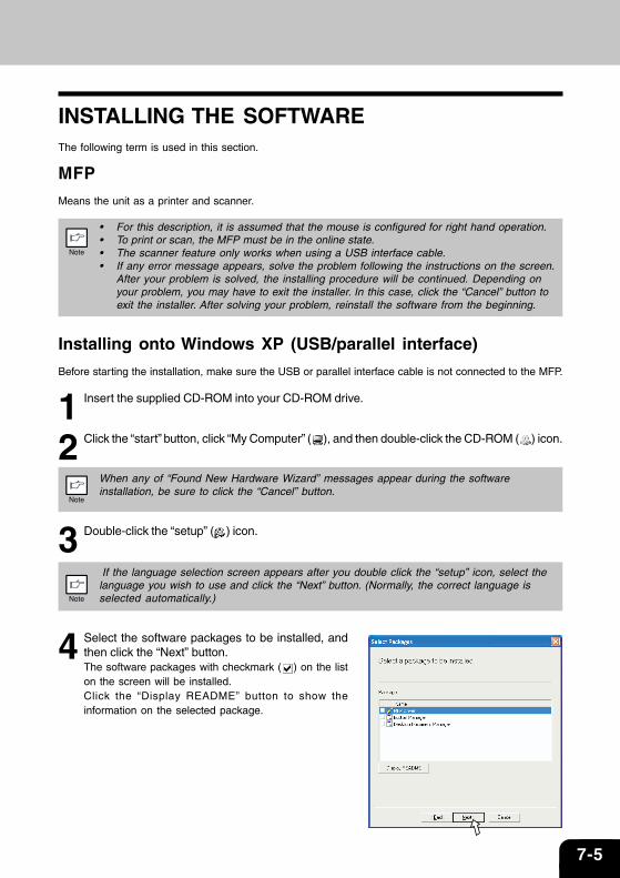
4 Select the software packages to be installed, andthen click the “Next” button.The software packages with checkmark ( ) on the liston the screen will be installed. Click the “Display README” button to show theinformation on the selected package.
7-6 INSTALL THE SOFTWARE
• If you are using the parallel interface connection, do not select the Button Managercheckbox because this feature is not supported with the parallel interface.
• If the following screen appears, click the “OK” button. Review the contents in See“BEFORE INSTALLATION” (p.7-3), and then select only appropriate the softwarepackages to be installed.
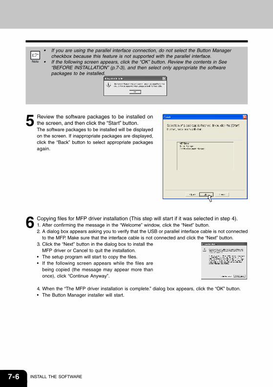
5 Review the software packages to be installed onthe screen, and then click the “Start” button.The software packages to be installed will be displayedon the screen. If inappropriate packages are displayed,click the “Back” button to select appropriate packagesagain.
6 Copying files for MFP driver installation (This step will start if it was selected in step 4).1. After confirming the message in the “Welcome” window, click the “Next” button.2. A dialog box appears asking you to verify that the USB or parallel interface cable is not connected
to the MFP. Make sure that the interface cable is not connected and click the “Next” button.3. Click the “Next” button in the dialog box to install the
MFP driver or Cancel to quit the installation.• The setup program will start to copy the files.• If the following screen appears while the files are
being copied (the message may appear more thanonce), click “Continue Anyway”.
4. When the “The MFP driver installation is complete.” dialog box appears, click the “OK” button.• The Button Manager installer will start.

7-7
7 Begin installation of the Button Manager (This step will start if it was selected in step 4).1. After confirming the message in the “Welcome” window, click the “Next” button.2. Read the message in the “Please read the following information.” window, and then click the “Next”
button.3. When a message appears that lets you specify the location for the software to be installed, click the
“Next” button.4. If the program displays “Do you want the Button Manager added to Windows Startup?”, check
“Yes” and click the “OK” button.• The setup program will start to copy the files.5. Click the “Finish” button when the message informs you that setup is successful.• The Desktop Document Manager installer will start.
8 Begin installation of the Desktop Document Manager (This step will start if it was selected instep 4).1. After confirming the message in the “Welcome to Desktop Document Manager installation” window,
click the “Next” button.2. Read the message in the “Information” window, and then click the “Next” button.3. When the “Choose Destination Location” window appears, click the “Next” button.4. When the “Select Program Folder” window appears, click the “Next” button.• The setup program will start to copy the files.5. Click the “Finish” button when the message informs you that Setup is complete.
9 Click the “Close” button when the message informsyou that “Setup has finished”. When the “Now connectthe MFP interface cable to the PC” dialog boxappears, click the “OK” button.
After the installation, a message to restart yourcomputer may be displayed. In this case, click the“Yes” button to restart your computer.

7-8 INSTALL THE SOFTWARE
10 Connect the USB interface cable or parallel interface cable. (See p. 7-29)Windows will detect the MFP and the Plug and Play screen will appear. If you are using WindowsXP with the parallel interface, go to step 12.
11 Begin installation of the scanner driver.1. “TOSHIBA e-STUDIOxxx” (where xxx is the model name of your MFP) will appear in the “Found
New Hardware Wizard” dialog box. Select “Install the software automatically (Recommended)”and click the “Next” button.
2. The “Install hardware” dialog box will appear. Click the “Continue Anyway” button.3. When installation of the driver is completed, click the “Finish” button to finish the scanner driver
installation.
12 Begin installation of the printer driver.1. “TOSHIBA e-STUDIOxxx” (where xxx is the model name of your MFP) will appear in the “Found
New Hardware Wizard” dialog box. Select “Install the software automatically (Recommended)”and click the “Next” button.
2. The “Hardware Installation” dialog box will appear. Click the “Continue Anyway” button.3. When installation of the driver is completed, click the “Finish” button to finish the printer driver
installation.You have completed the installation of all the software.

7-9
Installing onto Windows 98/Me/2000 (USB interface)
Before starting the installation, make sure the USB interface cable is not connected to the MFP.
1 Insert the supplied CD-ROM into your CD-ROM drive.
2 Double-click “My Computer” ( ), and then double-click the CD-ROM ( ) icon.
When any of “Hardware Found”, or “Found New Hardware Wizard” messages appearduring the software installation, be sure to click the “Cancel” button.
3 Double-click the “setup” ( ) icon.
If the language selection screen appears after you double click the “setup” icon, select thelanguage you wish to use and click the “Next” button. (Normally, the correct language isselected automatically.)
4 Select the software packages to be installed, andthen click the “Next” button.The software packages with checkmark ( ) on the liston the screen will be installed. Click the “DisplayREADME” button to show the information on the selectedpackage.
If the following screen appears, click the “OK” button. Review the contents in “BEFOREINSTALLATION” (See p. 7-3), and then select the appropriate driver software packages to beinstalled.
5 Review the software packages to be installed on the screen, and then click the “Start” button.The software packages to be installed will be displayed on the screen. If inappropriate packages aredisplayed, click the “Back” button to select appropriate packages again.
7-10 INSTALL THE SOFTWARE
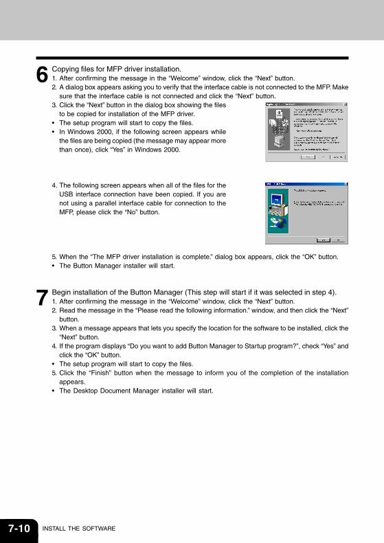
6 Copying files for MFP driver installation.1. After confirming the message in the “Welcome” window, click the “Next” button.2. A dialog box appears asking you to verify that the interface cable is not connected to the MFP. Make
sure that the interface cable is not connected and click the “Next” button.3. Click the “Next” button in the dialog box showing the files
to be copied for installation of the MFP driver.• The setup program will start to copy the files.• In Windows 2000, if the following screen appears while
the files are being copied (the message may appear morethan once), click “Yes” in Windows 2000.
4. The following screen appears when all of the files for theUSB interface connection have been copied. If you arenot using a parallel interface cable for connection to theMFP, please click the “No” button.
5. When the “The MFP driver installation is complete.” dialog box appears, click the “OK” button.• The Button Manager installer will start.
7 Begin installation of the Button Manager (This step will start if it was selected in step 4).1. After confirming the message in the “Welcome” window, click the “Next” button.2. Read the message in the “Please read the following information.” window, and then click the “Next”
button.3. When a message appears that lets you specify the location for the software to be installed, click the
“Next” button.4. If the program displays “Do you want to add Button Manager to Startup program?”, check “Yes” and
click the “OK” button.• The setup program will start to copy the files.5. Click the “Finish” button when the message to inform you of the completion of the installation
appears.• The Desktop Document Manager installer will start.
7-11
8 Begin installation of the Desktop Document Manager (This step will start if it was selected instep 4).1. After confirming the message in the “Welcome to Desktop Document Manager installation” window,
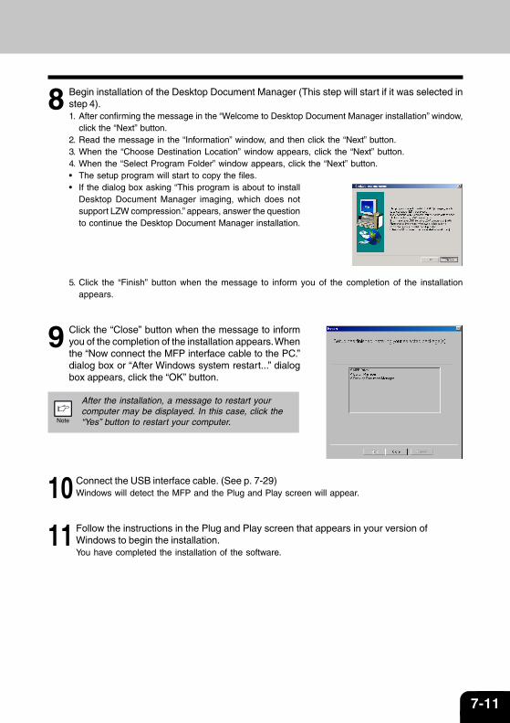
click the “Next” button.2. Read the message in the “Information” window, and then click the “Next” button.3. When the “Choose Destination Location” window appears, click the “Next” button.4. When the “Select Program Folder” window appears, click the “Next” button.• The setup program will start to copy the files.• If the dialog box asking “This program is about to install
Desktop Document Manager imaging, which does notsupport LZW compression.” appears, answer the questionto continue the Desktop Document Manager installation.
5. Click the “Finish” button when the message to inform you of the completion of the installationappears.
9 Click the “Close” button when the message to informyou of the completion of the installation appears. Whenthe “Now connect the MFP interface cable to the PC.”dialog box or “After Windows system restart...” dialogbox appears, click the “OK” button.
After the installation, a message to restart yourcomputer may be displayed. In this case, click the“Yes” button to restart your computer.
10 Connect the USB interface cable. (See p. 7-29)Windows will detect the MFP and the Plug and Play screen will appear.
11 Follow the instructions in the Plug and Play screen that appears in your version ofWindows to begin the installation.You have completed the installation of the software.
7-12 INSTALL THE SOFTWARE
Installing onto Windows 95/98/Me/NT4.0/2000 (Parallel interface)
Before starting the installation, make sure the USB or parallel interface cable is not connected to the MFP.
1 Insert the supplied CD-ROM into your CD-ROM drive.
2 Double-click “My Computer” ( ), and then double-click the CD-ROM ( ) icon.
When any of “Hardware Found”, or “Found New Hardware Wizard” messages appearduring the software installation, be sure to click the “Cancel” button.
3 Double-click the “setup” ( ) icon.
If the language selection screen appears after you double click the “setup” icon, select thelanguage you wish to use and click the “Next” button. (Normally, the correct language isselected automatically.)
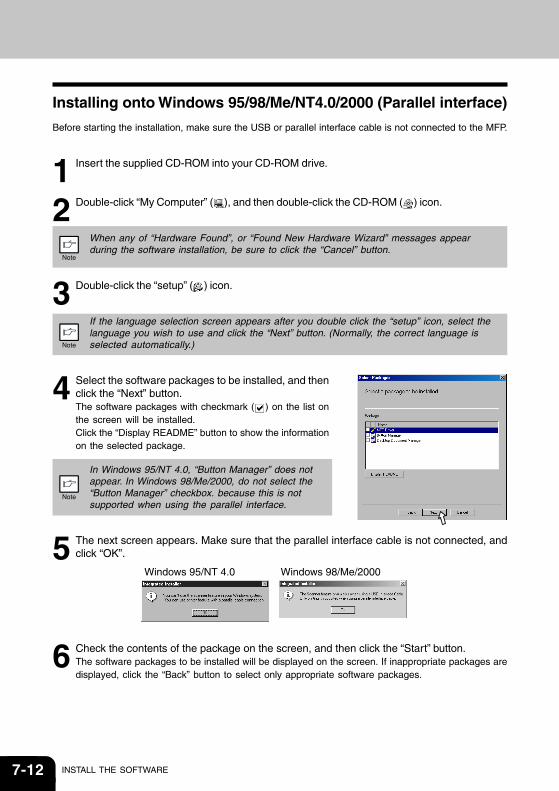
4 Select the software packages to be installed, and thenclick the “Next” button.The software packages with checkmark ( ) on the list onthe screen will be installed.Click the “Display README” button to show the informationon the selected package.
In Windows 95/NT 4.0, “Button Manager” does notappear. In Windows 98/Me/2000, do not select the“Button Manager” checkbox. because this is notsupported when using the parallel interface.
5 The next screen appears. Make sure that the parallel interface cable is not connected, andclick “OK”.
6 Check the contents of the package on the screen, and then click the “Start” button.The software packages to be installed will be displayed on the screen. If inappropriate packages aredisplayed, click the “Back” button to select only appropriate software packages.
Windows 95/NT 4.0 Windows 98/Me/2000
7-13
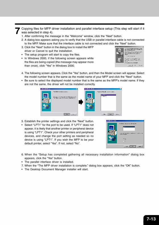
7 Copying files for MFP driver installation and parallel interface setup (This step will start if itwas selected in step 4).1. After confirming the message in the “Welcome” window, click the “Next” button.2. A dialog box appears asking you to verify that the USB or parallel interface cable is not connected
to the MFP. Make sure that the interface cable is not connected and click the “Next” button.3. Click the “Next” button in the dialog box to install the MFP
driver or Cancel to quit the installation.• The setup program will start to copy the files.• In Windows 2000, if the following screen appears while
the files are being copied (the message may appear morethan once), click “Yes” in Windows 2000.
4. The following screen appears. Click the “Yes” button, and then the Model screen will appear. Selectthe model number that is the same as the model name of your MFP and click the “Next” button.
• Be sure to select the displayed model number that is the same as the MFP’s model name. If theyare not the same, the driver will not be installed correctly.
5. Establish the printer settings and click the “Next” button.• Select “LPT1” for the port to be used. If “LPT1” does not
appear, it is likely that another printer or peripheral deviceis using “LPT1”. Check your other printers and peripheraldevices, and change the port setting as needed so nodevice is using “LPT1”. If you wish the MFP to be yourdefault printer, select “Yes”. If not, select “No”.
6. When the “Setup has completed gathering all necessary installation information” dialog box
appears, click the “Yes” button.• The parallel interface driver is installed.7. When the “The MFP driver installation is complete.” dialog box appears, click the “OK” button.• The Desktop Document Manager installer will start.

7-14 INSTALL THE SOFTWARE
8 Begin installation of the Desktop Document Manager (This step will start if it was selected instep 4).1. After confirming the message in the “Welcome to Desktop Document Manager installation” window,
click the “Next” button.2. Read the message in the “Information” window, and then click the “Next” button.3. When the “Choose Destination Location” window appears, click the “Next” button.4. When the “Select Program Folder” window appears, click
the “Next” button.• The setup program will start to copy the files.• If the dialog box asking “This program is about to install
Desktop Document Manager imaging, which does notsupport LZW compression.” appears, answer thequestion to continue the Desktop Document Managerinstallation.
5. Click the “Finish” button when the message to inform you of the completion of the installationappears.
9 Click the “Close” button when the message toinform you of the completion of the installationappears.When the “Now connect the MFP interface cable tothe PC.” dialog box or “After Windows systemrestart...” dialog box appears, click the “OK” button.
After the installation, a message to restart yourcomputer may be displayed. In this case, clickthe “Yes” button to restart your computer.
10 Connect the parallel interface cable. (p.7-30)You have completed the installation of all the software.
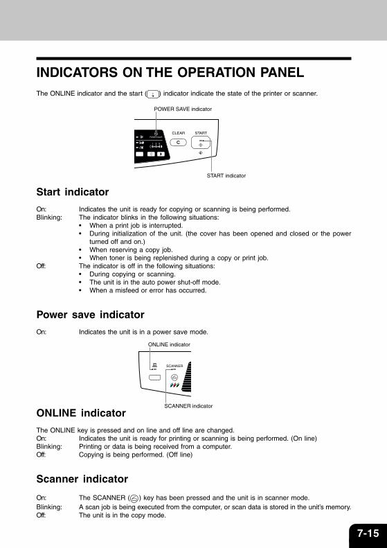
7-15
SCANNER indicator
ONLINE indicator
POWER SAVE indicator
START indicator
INDICATORS ON THE OPERATION PANELThe ONLINE indicator and the start ( ) indicator indicate the state of the printer or scanner.
Start indicator
On: Indicates the unit is ready for copying or scanning is being performed.Blinking: The indicator blinks in the following situations:
• When a print job is interrupted.• During initialization of the unit. (the cover has been opened and closed or the power
turned off and on.)• When reserving a copy job.• When toner is being replenished during a copy or print job.
Off: The indicator is off in the following situations:• During copying or scanning.• The unit is in the auto power shut-off mode.• When a misfeed or error has occurred.
Power save indicator
On: Indicates the unit is in a power save mode.
ONLINE indicator
The ONLINE key is pressed and on line and off line are changed.On: Indicates the unit is ready for printing or scanning is being performed. (On line)Blinking: Printing or data is being received from a computer.Off: Copying is being performed. (Off line)
Scanner indicator
On: The SCANNER ( ) key has been pressed and the unit is in scanner mode.Blinking: A scan job is being executed from the computer, or scan data is stored in the unit’s memory.Off: The unit is in the copy mode.
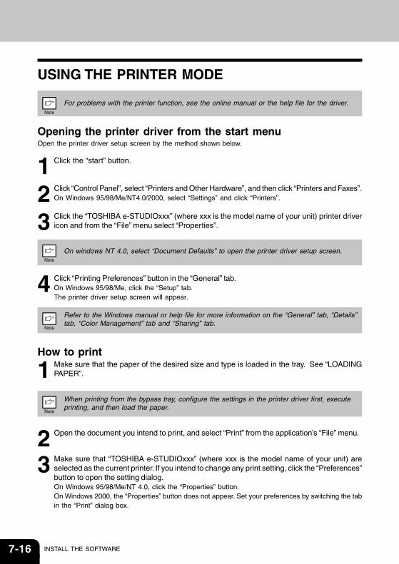
7-16 INSTALL THE SOFTWARE
USING THE PRINTER MODE For problems with the printer function, see the online manual or the help file for the driver.
Opening the printer driver from the start menuOpen the printer driver setup screen by the method shown below.
1 Click the “start” button.
2 Click “Control Panel”, select “Printers and Other Hardware”, and then click “Printers and Faxes”.On Windows 95/98/Me/NT4.0/2000, select “Settings” and click “Printers”.
3 Click the “TOSHIBA e-STUDIOxxx” (where xxx is the model name of your unit) printer drivericon and from the “File” menu select “Properties”.
On windows NT 4.0, select “Document Defaults” to open the printer driver setup screen.
4 Click “Printing Preferences” button in the “General” tab.On Windows 95/98/Me, click the “Setup” tab.The printer driver setup screen will appear.
Refer to the Windows manual or help file for more information on the “General” tab, “Details”tab, “Color Management” tab and “Sharing” tab.
How to print
1 Make sure that the paper of the desired size and type is loaded in the tray. See “LOADINGPAPER”.
When printing from the bypass tray, configure the settings in the printer driver first, executeprinting, and then load the paper.
2 Open the document you intend to print, and select “Print” from the application’s “File” menu.
3 Make sure that “TOSHIBA e-STUDIOxxx” (where xxx is the model name of your unit) areselected as the current printer. If you intend to change any print setting, click the “Preferences”button to open the setting dialog.On Windows 95/98/Me/NT 4.0, click the “Properties” button.On Windows 2000, the “Properties” button does not appear. Set your preferences by switching the tabin the “Print” dialog box.
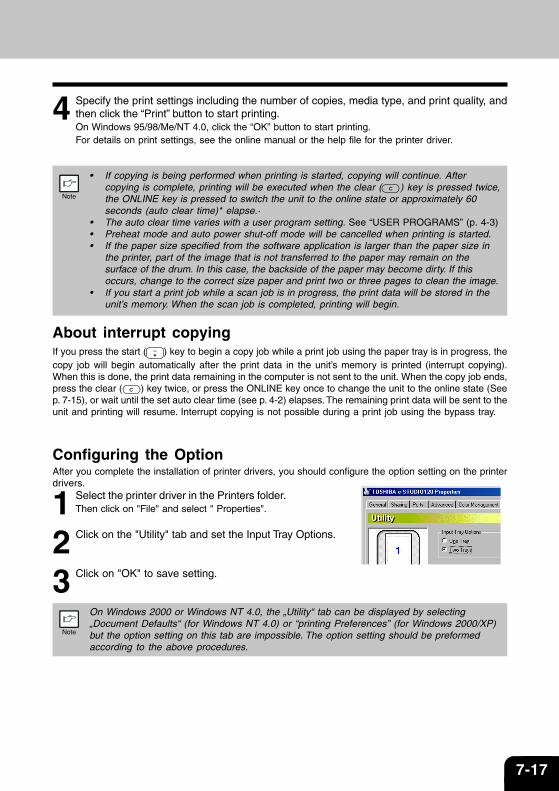
7-17
4 Specify the print settings including the number of copies, media type, and print quality, andthen click the “Print” button to start printing.On Windows 95/98/Me/NT 4.0, click the “OK” button to start printing.For details on print settings, see the online manual or the help file for the printer driver.
• If copying is being performed when printing is started, copying will continue. After
copying is complete, printing will be executed when the clear ( ) key is pressed twice,the ONLINE key is pressed to switch the unit to the online state or approximately 60seconds (auto clear time)* elapse.·
• The auto clear time varies with a user program setting. See “USER PROGRAMS” (p. 4-3)• Preheat mode and auto power shut-off mode will be cancelled when printing is started.• If the paper size specified from the software application is larger than the paper size in
the printer, part of the image that is not transferred to the paper may remain on thesurface of the drum. In this case, the backside of the paper may become dirty. If thisoccurs, change to the correct size paper and print two or three pages to clean the image.
• If you start a print job while a scan job is in progress, the print data will be stored in theunit’s memory. When the scan job is completed, printing will begin.
About interrupt copyingIf you press the start ( ) key to begin a copy job while a print job using the paper tray is in progress, thecopy job will begin automatically after the print data in the unit’s memory is printed (interrupt copying).When this is done, the print data remaining in the computer is not sent to the unit. When the copy job ends,press the clear ( ) key twice, or press the ONLINE key once to change the unit to the online state (Seep. 7-15), or wait until the set auto clear time (see p. 4-2) elapses. The remaining print data will be sent to theunit and printing will resume. Interrupt copying is not possible during a print job using the bypass tray.
Configuring the OptionAfter you complete the installation of printer drivers, you should configure the option setting on the printerdrivers.
1 Select the printer driver in the Printers folder.Then click on "File" and select " Properties".
2 Click on the "Utility" tab and set the Input Tray Options.
3 Click on "OK" to save setting.
On Windows 2000 or Windows NT 4.0, the „Utility“ tab can be displayed by selecting„Document Defaults“ (for Windows NT 4.0) or “printing Preferences” (for Windows 2000/XP)but the option setting on this tab are impossible. The option setting should be preformedaccording to the above procedures.

7-18 INSTALL THE SOFTWARE
USING THE SCANNER MODE For problems with the scanner function, see the online manual or the help file for the driver.
Using the Button ManagerSetting up the Button Manager
The scanner driver for this unit includes an STI (Still image) driver and WIA (Windows Image Acquisition)driver. You can install software that supports the STI driver and WIA driver to enable scanning using onlythe operation panel of the unit.The Button Manager accessory software supports the STI driver and WIA driver. Setup that is required inWindows to use the Button Manager is explained in the following.
Windows XP
1 Click the “start” button, select “Control Panel” and click “Printers and Other Hardware”, andthen click “Scanners and Cameras” in the start menu. Right click the “TOSHIBA e-STUDIOxxx”(where xxx is the model name of your unit) icon and click “Properties” in the menu thatappears.
2 In the “Properties” screen, click the “Events” tab.
3 Click the “Select an event” button and select“ScanMenu SC1” from the pull-down menu. Select“Button Manager (TOSHIBA Personal MFP series)”in “Start this program” and click “Apply”.
If you prefer a specific application to be opened instead ofButton Manager, refer to page 20 of the Online manual. Donot make the application selection in this screen.
4 Repeat Step3 to set “ScanMenu SC2” through “ScanMenu SC6” .Click the “Select an event” button and select “ScanMenu SC2” from the pull-down menu. Select“Button Manager (TOSHIBA Personal MFP series)” in “Start this program” and click “Apply”. Do thesame for each ScanMenu through “ScanMenu SC6”.When the settings have been completed, click the “OK” button to close the screen. When the settingshave been completed in Windows, start the Button Manager. Adjust detailed settings and then scanan image from the unit. For the procedures for starting Button Manager and adjusting settings, seeSee “SCAN PARAMETER SETTING DIALOG BOX” (P. 7-20).
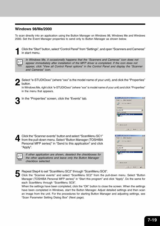
7-19
Windows 98/Me/2000
To scan directly into an application using the Button Manager on Windows 98, Windows Me and Windows2000. Set the Event Manager properties to send only to Button Manager as shown below.
1 Click the “Start” button, select “Control Panel” from “Settings”, and open “Scanners and Cameras”in start menu.
In Windows Me, it occasionally happens that the “Scanners and Cameras” icon does notappear immediately after installation of the MFP driver is completed. If the icon does notappear, click “View all Control Panel options” in the Control Panel and display the “Scannerand Cameras” icon.
2 Select “e-STUDIOxxx” (where “xxx” is the model name of your unit), and click the “Properties”button.In Windows Me, right click “e-STUDIOxxx” (where “xxx” is model name of your unit) and click “Properties”in the menu that appears.
3 In the “Properties” screen, click the “Events” tab.
4 Click the “Scanner events” button and select “ScanMenu SC1”from the pull-down menu. Select “Button Manager (TOSHIBAPersonal MFP series)” in “Send to this application” and click“Apply”.
If other application are shown, deselect the checkboxes forthe other applications and leave only the Button Managercheckbox selected.
5 Repeat Step4 to set “ScanMenu SC2” through “ScanMenu SC6”.Click the “Scanner events” and select “ScanMenu SC2” from the pull-down menu. Select “ButtonManager (TOSHIBA Personal MFP series)” in “Start this program” and click “Apply”. Do the same foreach ScanMenu through “ScanMenu SC6”.When the settings have been completed, click the “OK” button to close the screen. When the settingshave been completed in Windows, start the Button Manager. Adjust detailed settings and then scanan image from the unit. For the procedures for starting Button Manager and adjusting settings, see“Scan Parameter Setting Dialog Box” (Next page).
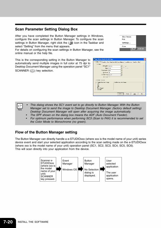
7-20 INSTALL THE SOFTWARE
Scan Parameter Setting Dialog Box
After you have completed the Button Manager settings in Windows,configure the scan settings in Button Manager. To configure the scansettings in Button Manager, right click the ( ) icon in the Taskbar andselect “Setting” from the menu that appears.For details on configuring the scan settings in Button Manager, see theonline manual or the help file.
This is the corresponding setting in the Button Manager toautomatically send multiple images in full color at 75 dpi toDesktop Document Manager using the operation panel “SC1”SCANNER ( ) key selection.
• This dialog shows the SC1 event set to go directly to Button Manager. With the Button
Manager set to send the image to Desktop Document Manager. (factory default setting)Desktop Document Manager will open after acquiring the image automatically.
• The SPF shown on the dialog box means the ADF (Auto Document Feeder).• For optimum performance when performing SC3 (Scan to FAX) it is recommended to set
the Color Mode to Monochrome (no green).
Flow of the Button Manager setting
The Button Manager can directly handle a e-STUDIOxxx (where xxx is the model name of your unit) seriesdevice event and start your selected application according to the scan setting made on the e-STUDIOxxx(where xxx is the model name of your unit) operation panel (SC1, SC2, SC3, SC4, SC5, SC6).This will scan directly into your application from the device.
Scanner e-STUDIOxxx (where xxx is the model name of your unit) SCANNER key pressed.
Event Manager
Windows OS
Button Manager
No Selection dialog is displayed.
User selected application
The user application opens.
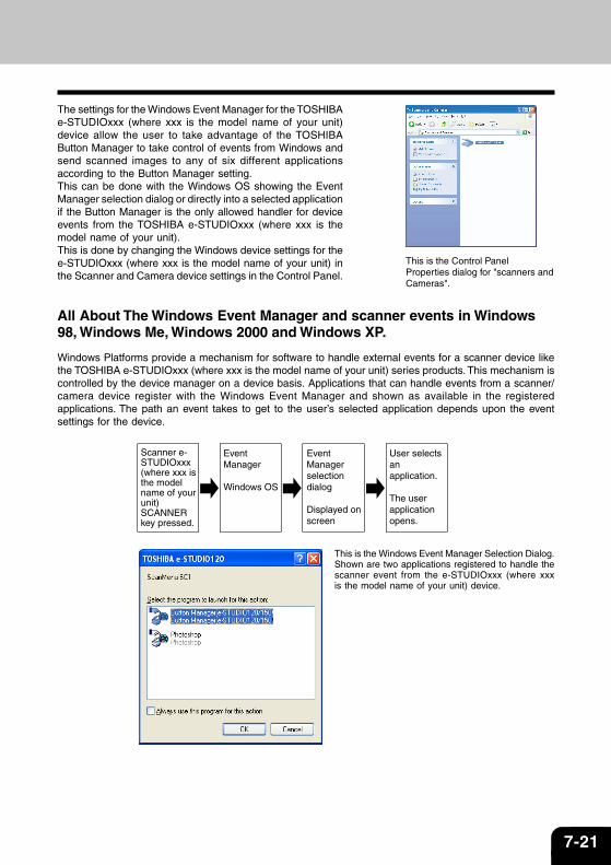
7-21
The settings for the Windows Event Manager for the TOSHIBAe-STUDIOxxx (where xxx is the model name of your unit)device allow the user to take advantage of the TOSHIBAButton Manager to take control of events from Windows andsend scanned images to any of six different applicationsaccording to the Button Manager setting.This can be done with the Windows OS showing the EventManager selection dialog or directly into a selected applicationif the Button Manager is the only allowed handler for deviceevents from the TOSHIBA e-STUDIOxxx (where xxx is themodel name of your unit).This is done by changing the Windows device settings for thee-STUDIOxxx (where xxx is the model name of your unit) inthe Scanner and Camera device settings in the Control Panel.
All About The Windows Event Manager and scanner events in Windows98, Windows Me, Windows 2000 and Windows XP.
Windows Platforms provide a mechanism for software to handle external events for a scanner device likethe TOSHIBA e-STUDIOxxx (where xxx is the model name of your unit) series products. This mechanism iscontrolled by the device manager on a device basis. Applications that can handle events from a scanner/camera device register with the Windows Event Manager and shown as available in the registeredapplications. The path an event takes to get to the user’s selected application depends upon the eventsettings for the device.
This is the Control PanelProperties dialog for "scanners andCameras".
Scanner e-STUDIOxxx (where xxx is the model name of your unit) SCANNER key pressed.
Event Manager
Windows OS
Event Managerselection dialog
Displayed on screen
User selects an application.
The user application opens.
This is the Windows Event Manager Selection Dialog.Shown are two applications registered to handle thescanner event from the e-STUDIOxxx (where xxxis the model name of your unit) device.
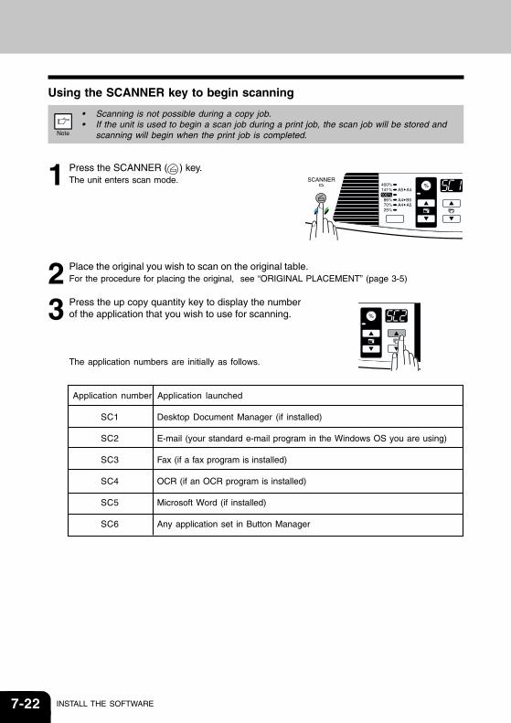
7-22 INSTALL THE SOFTWARE
Using the SCANNER key to begin scanning
• Scanning is not possible during a copy job.• If the unit is used to begin a scan job during a print job, the scan job will be stored and
scanning will begin when the print job is completed.
1 Press the SCANNER ( ) key.The unit enters scan mode.
2 Place the original you wish to scan on the original table.For the procedure for placing the original, see “ORIGINAL PLACEMENT” (page 3-5)
3 Press the up copy quantity key to display the numberof the application that you wish to use for scanning.
The application numbers are initially as follows.
Application number Application launched
SC1 Desktop Document Manager (if installed)
SC2 E-mail (your standard e-mail program in the Windows OS you are using)
SC3 Fax (if a fax program is installed)
SC4 OCR (if an OCR program is installed)
SC5 Microsoft Word (if installed)
SC6 Any application set in Button Manager
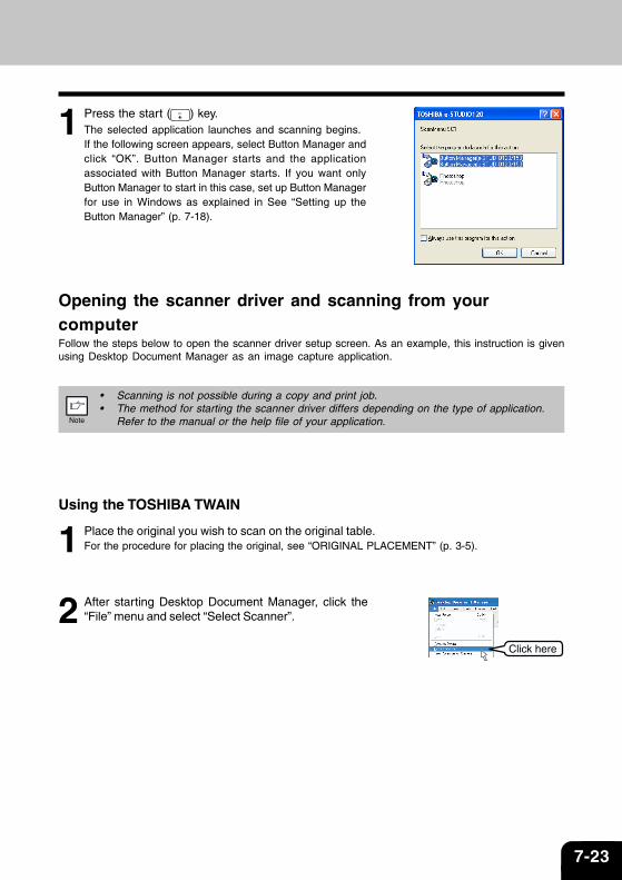
7-23
1 Press the start ( ) key.The selected application launches and scanning begins.If the following screen appears, select Button Manager andclick “OK”. Button Manager starts and the applicationassociated with Button Manager starts. If you want onlyButton Manager to start in this case, set up Button Managerfor use in Windows as explained in See “Setting up theButton Manager” (p. 7-18).
Opening the scanner driver and scanning from yourcomputerFollow the steps below to open the scanner driver setup screen. As an example, this instruction is givenusing Desktop Document Manager as an image capture application.
• Scanning is not possible during a copy and print job.• The method for starting the scanner driver differs depending on the type of application.
Refer to the manual or the help file of your application.
Using the TOSHIBA TWAIN
1 Place the original you wish to scan on the original table.For the procedure for placing the original, see “ORIGINAL PLACEMENT” (p. 3-5).
2 After starting Desktop Document Manager, click the“File” menu and select “Select Scanner”.
Click here
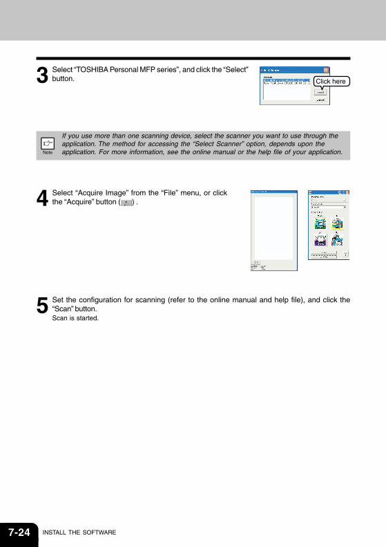
7-24 INSTALL THE SOFTWARE
3 Select “TOSHIBA Personal MFP series”, and click the “Select”button.
If you use more than one scanning device, select the scanner you want to use through theapplication. The method for accessing the “Select Scanner” option, depends upon theapplication. For more information, see the online manual or the help file of your application.
4 Select “Acquire Image” from the “File” menu, or clickthe “Acquire” button ( ) .
5 Set the configuration for scanning (refer to the online manual and help file), and click the“Scan” button.Scan is started.
Click here
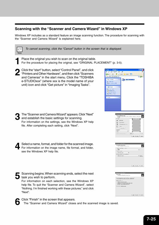
7-25
Scanning with the “Scanner and Camera Wizard” in Windows XP
Windows XP includes as a standard feature an image scanning function. The procedure for scanning withthe “Scanner and Camera Wizard” is explained here.
To cancel scanning, click the “Cancel” button in the screen that is displayed.
1 Place the original you wish to scan on the original table.For the procedure for placing the original, see “ORIGINAL PLACEMENT” (p. 3-5).
2 Click the “start” button, select “Control Panel”, and click“Printers and Other Hardware”, and then click “Scannersand Cameras” in the start menu. Click the “TOSHIBAe-STUDIOxxx” (where xxx is the model name of yourunit) icon and click “Get picture” in “Imaging Tasks”.
3 The “Scanner and Camera Wizard” appears. Click “Next”and establish the basic settings for scanning.For information on the settings, see the Windows XP helpfile. After completing each setting, click “Next”.
4 Select a name, format, and folder for the scanned image.For information on the image name, file format, and folder,see the Windows XP help file.
5 Scanning begins. When scanning ends, select the nexttask you wish to perform.For information on each selection, see the Windows XPhelp file. To quit the “Scanner and Camera Wizard”, select“Nothing. I’m finished working with these pictures.” and click“Next”.
6 Click “Finish” in the screen that appears.The “Scanner and Camera Wizard” closes and the scanned image is saved.
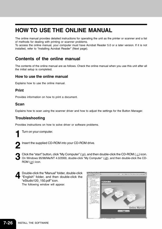
7-26 INSTALL THE SOFTWARE
HOW TO USE THE ONLINE MANUALThe online manual provides detailed instructions for operating the unit as the printer or scanner and a listof methods for dealing with printing or scanner problems.To access the online manual, your computer must have Acrobat Reader 5.0 or a later version. If it is notinstalled, refer to “Installing Acrobat Reader” (Next page).
Contents of the online manual
The contents of the online manual are as follows. Check the online manual when you use this unit after allthe initial setup is completed.
How to use the online manual
Explains how to use the online manual.
Provides information on how to print a document.
Scan
Explains how to scan using the scanner driver and how to adjust the settings for the Button Manager.
Troubleshooting
Provides instructions on how to solve driver or software problems.
1 Turn on your computer.
2 Insert the supplied CD-ROM into your CD-ROM drive.
3 Click the “start” button, click “My Computer” ( ), and then double-click the CD-ROM ( ) icon.On Windows 95/98/Me/NT 4.0/2000, double-click “My Computer” ( ), and then double-click the CD-ROM ( ) icon.
4 Double-click the “Manual” folder, double-click“English” folder, and then double-click the“eStudio120_150.pdf” icon.The following window will appear.
7-27
5 Click the to read the online manual.To close the online manual, click the ( ) button located at the top-right of the window.
• The online manual can be printed out using Acrobat Reader. TOSHIBA recommendsprinting out the sections which you refer to regularly.
• Refer to “Help” of Acrobat Reader for more details on the operation and function ofAcrobat Reader.
Installing Acrobat Reader
1 Turn on your computer.
2 Insert the CD-ROM into the CD-ROM drive.
3 Click the “start” button, click “My Computer” ( ), and then double-click the CD-ROM ( ) icon.On Windows 95/98/Me/NT 4.0/2000, double-click “My Computer” ( ), and then double-click the CD-ROM ( ) icon.
4 Double-click the “Acrobat” folder, and then double-click the “ar500enu.exe” icon.Follow the on-screen instructions to install Acrobat Reader.
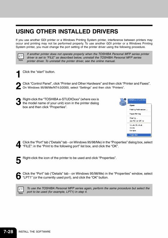
7-28 INSTALL THE SOFTWARE
USING OTHER INSTALLED DRIVERSIf you use another GDI printer or a Windows Printing System printer, interference between printers mayoccur and printing may not be performed properly. To use another GDI printer or a Windows PrintingSystem printer, you must change the port setting of the printer driver using the following procedure.
If another printer does not operate properly when the TOSHIBA Personal MFP series printerdriver is set to “FILE” as described below, uninstall the TOSHIBA Personal MFP seriesprinter driver. To uninstall the printer driver, see the online manual.
1 Click the “start” button.
2 Click “Control Panel”, click “Printer and Other Hardware” and then click “Printer and Faxes”.On Windows 95/98/Me/NT4.0/2000, select “Settings” and then click “Printers”.
3 Right-click the “TOSHIBA e-STUDIOxxx” (where xxx isthe model name of your unit) icon in the printer dialogbox and then click “Properties”.
4 Click the “Port” tab (“Details” tab - on Windows 95/98/Me) in the “Properties” dialog box, select“FILE”: in the “Print to the following port” list box, and click the “OK”.
5 Right-click the icon of the printer to be used and click “Properties”.
6 Click the “Port” tab (“Details” tab - on Windows 95/98/Me) in the “Properties” window, select“LPT1” (or the currently used port), and click the “OK” button.
To use the TOSHIBA Personal MFP series again, perform the same procedure but select theport to be used (for example, LPT1) in step 4.
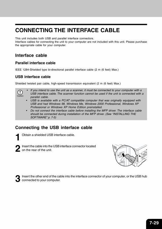
7-29
CONNECTING THE INTERFACE CABLEThis unit includes both USB and parallel interface connectors.Interface cables for connecting the unit to your computer are not included with this unit. Please purchasethe appropriate cable for your computer.
Interface cable
Parallel interface cable
IEEE 1284-Shielded type bi-directional parallel interface cable (2 m (6 feet) Max.)
USB interface cable
Shielded twisted pair cable, high-speed transmission equivalent (2 m (6 feet) Max.)
• If you intend to use the unit as a scanner, it must be connected to your computer with aUSB interface cable. The scanner function cannot be used if the unit is connected with aparallel cable.
• USB is available with a PC/AT compatible computer that was originally equipped withUSB and had Windows 98, Windows Me, Windows 2000 Professional, Windows XPProfessional or Windows XP Home Edition preinstalled.
• Do not connect the interface cable before installing the MFP driver. The interface cableshould be connected during installation of the MFP driver. (See “INSTALLING THESOFTWARE” p. 7-5)
Connecting the USB interface cable
1 Obtain a shielded USB interface cable.
2 Insert the cable into the USB interface connector locatedon the rear of the unit.
3 Insert the other end of the cable into the interface connector of your computer, or the USB hubconnected to your computer.
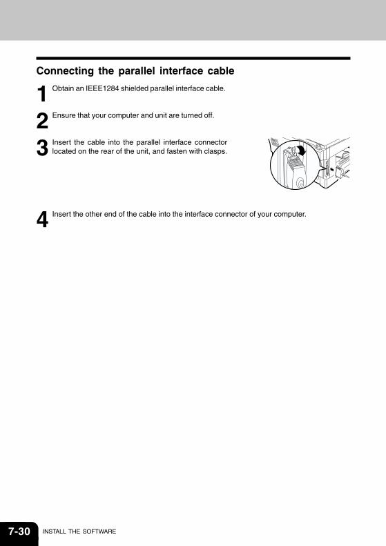
7-30 INSTALL THE SOFTWARE
Connecting the parallel interface cable
1 Obtain an IEEE1284 shielded parallel interface cable.
2 Ensure that your computer and unit are turned off.
3 Insert the cable into the parallel interface connectorlocated on the rear of the unit, and fasten with clasps.
4 Insert the other end of the cable into the interface connector of your computer.
8-1
Appendix
SPECIFICATIONS ...................................................................................................................8-2
OPTIONAL EQUIPMENT ........................................................................................................8-4
INDEX .....................................................................................................................................8-9
SOFTWARE LICENSE ......................................................................................................... 8-11
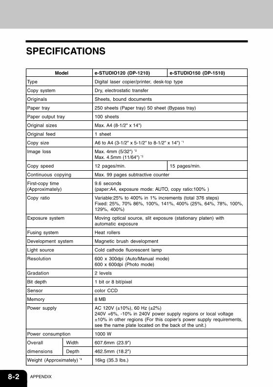
8-2 APPENDIX
SPECIFICATIONS
Model
Type
Copy system
Originals
Paper tray
Paper output tray
Original sizes
Original feed
Copy size
Image loss
Copy speed
Continuous copying
First-copy time(Approximately)
Copy ratio
Exposure system
Fusing system
Development system
Light source
Resolution
Gradation
Bit depth
Sensor
Memory
Power supply
Power consumption
Overall Width
dimensions Depth
Weight (Approximately) *4
e-STUDIO120 (DP-1210) e-STUDIO150 (DP-1510)
Digital laser copier/printer, desk-top type
Dry, electrostatic transfer
Sheets, bound documents
250 sheets (Paper tray) 50 sheet (Bypass tray)
100 sheets
Max. A4 (8-1/2" x 14")
1 sheet
A6 to A4 (3-1/2" x 5-1/2" to 8-1/2" x 14") *1
Max. 4mm (5/32") *2
Max. 4.5mm (11/64") *3
12 pages/min. 15 pages/min.
Max. 99 pages subtractive counter
9.6 seconds(paper:A4, exposure mode: AUTO, copy ratio:100% )
Variable:25% to 400% in 1% increments (total 376 steps)Fixed: 25%, 70% 86%, 100%, 141%, 400% (25%, 64%, 78%, 100%,129%, 400%)
Moving optical source, slit exposure (stationary platen) withautomatic exposure
Heat rollers
Magnetic brush development
Cold cathode fluorescent lamp
600 x 300dpi (Auto/Manual mode)600 x 600dpi (Photo mode)
2 levels
1 bit or 8 bit/pixel
color CCD
8 MB
AC 120V (±10%), 60 Hz (±2%)240V +6%, -10% in 240V power supply regions or local voltage±10% in other regions (For this copier’s power supply requirements,see the name plate located on the back of the unit.)
1000 W
607.6mm (23.9")
462.5mm (18.2")
16kg (35.3 lbs.)
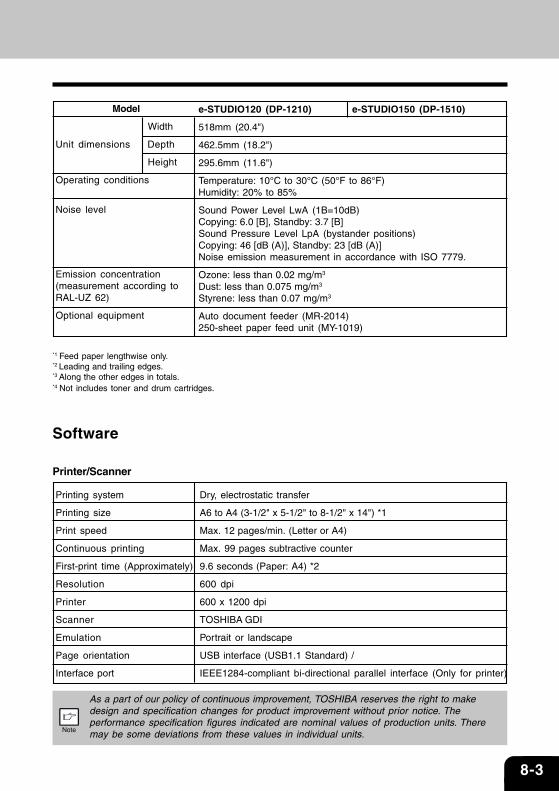
8-3
Model
Width
Unit dimensions Depth
Height
Operating conditions
Noise level
Emission concentration(measurement according toRAL-UZ 62)
Optional equipment
e-STUDIO120 (DP-1210) e-STUDIO150 (DP-1510)
518mm (20.4")
462.5mm (18.2")
295.6mm (11.6")
Temperature: 10°C to 30°C (50°F to 86°F)Humidity: 20% to 85%
Sound Power Level LwA (1B=10dB)Copying: 6.0 [B], Standby: 3.7 [B]Sound Pressure Level LpA (bystander positions)Copying: 46 [dB (A)], Standby: 23 [dB (A)]Noise emission measurement in accordance with ISO 7779.
Ozone: less than 0.02 mg/m3
Dust: less than 0.075 mg/m3
Styrene: less than 0.07 mg/m3
Auto document feeder (MR-2014)250-sheet paper feed unit (MY-1019)
*1 Feed paper lengthwise only.*2 Leading and trailing edges.*3 Along the other edges in totals.*4 Not includes toner and drum cartridges.
Software
Printer/Scanner
Printing system
Printing size
Print speed
Continuous printing
First-print time (Approximately)
Resolution
Printer
Scanner
Emulation
Page orientation
Interface port
Dry, electrostatic transfer
A6 to A4 (3-1/2" x 5-1/2" to 8-1/2" x 14") *1
Max. 12 pages/min. (Letter or A4)
Max. 99 pages subtractive counter
9.6 seconds (Paper: A4) *2
600 dpi
600 x 1200 dpi
TOSHIBA GDI
Portrait or landscape
USB interface (USB1.1 Standard) /
IEEE1284-compliant bi-directional parallel interface (Only for printer)
As a part of our policy of continuous improvement, TOSHIBA reserves the right to makedesign and specification changes for product improvement without prior notice. Theperformance specification figures indicated are nominal values of production units. Theremay be some deviations from these values in individual units.
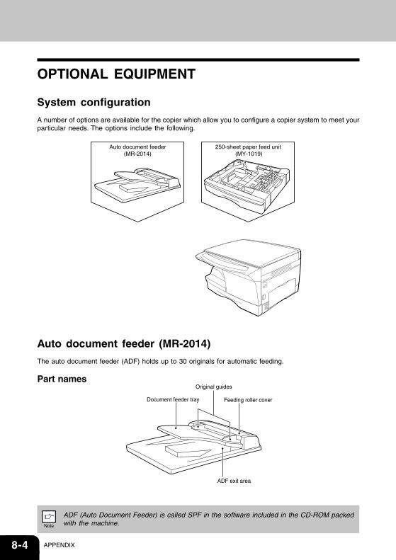
8-4 APPENDIX
OPTIONAL EQUIPMENT
System configuration
A number of options are available for the copier which allow you to configure a copier system to meet yourparticular needs. The options include the following.
Auto document feeder (MR-2014)
The auto document feeder (ADF) holds up to 30 originals for automatic feeding.
Part names
ADF (Auto Document Feeder) is called SPF in the software included in the CD-ROM packedwith the machine.
Auto document feeder(MR-2014)
250-sheet paper feed unit (MY-1019)
Document feeder tray Feeding roller cover
Original guides
ADF exit area
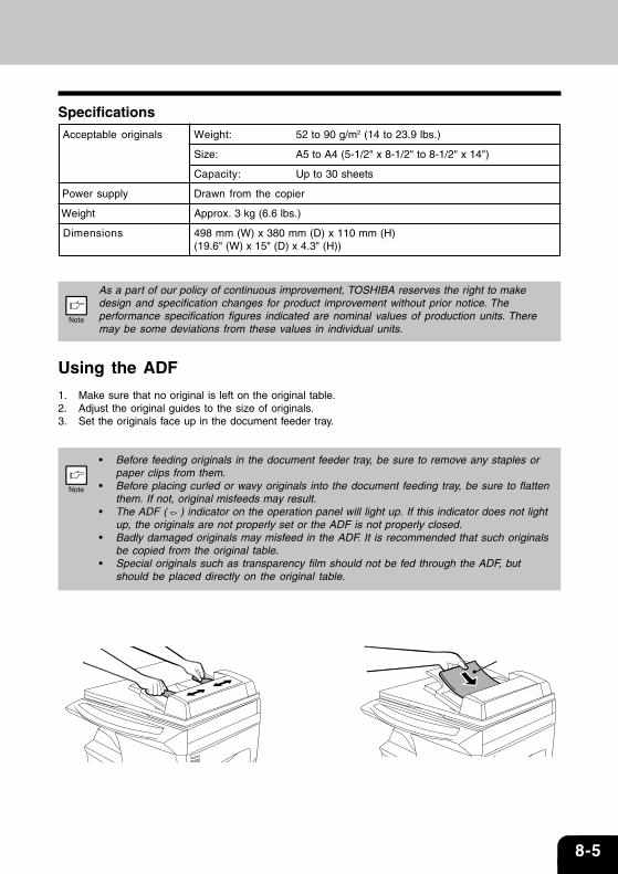
8-5
Specifications Acceptable originals Weight: 52 to 90 g/m2 (14 to 23.9 lbs.)
Size: A5 to A4 (5-1/2" x 8-1/2" to 8-1/2" x 14")
Capacity: Up to 30 sheets
Power supply Drawn from the copier
Weight Approx. 3 kg (6.6 lbs.)
Dimensions 498 mm (W) x 380 mm (D) x 110 mm (H)(19.6" (W) x 15" (D) x 4.3" (H))
As a part of our policy of continuous improvement, TOSHIBA reserves the right to makedesign and specification changes for product improvement without prior notice. Theperformance specification figures indicated are nominal values of production units. Theremay be some deviations from these values in individual units.
Using the ADF
1. Make sure that no original is left on the original table.2. Adjust the original guides to the size of originals.3. Set the originals face up in the document feeder tray.
• Before feeding originals in the document feeder tray, be sure to remove any staples orpaper clips from them.
• Before placing curled or wavy originals into the document feeding tray, be sure to flattenthem. If not, original misfeeds may result.
• The ADF ( ) indicator on the operation panel will light up. If this indicator does not lightup, the originals are not properly set or the ADF is not properly closed.
• Badly damaged originals may misfeed in the ADF. It is recommended that such originalsbe copied from the original table.
• Special originals such as transparency film should not be fed through the ADF, butshould be placed directly on the original table.
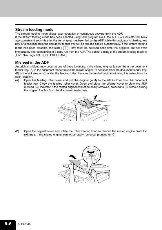
8-6 APPENDIX
Stream feeding modeThe stream feeding mode allows easy operation of continuous copying from the ADF.If the stream feeding mode has been enabled using user program No.4, the ADF ( ) indicator will blinkapproximately 5 seconds after the last original has been fed by the ADF. While this indicator is blinking, anynew originals placed in the document feeder tray will be fed and copied automatically. If the stream feedingmode has been disabled, the start ( ) key must be pressed each time the originals are set evenimmediately after completion of a copy run from the ADF. The default setting of the stream feeding mode is„ON“. See page 4-3, USER PROGRAMS.
Misfeed in the ADFAn original misfeed may occur at one of three locations: if the misfed original is seen from the documentfeeder tray, (A) in the document feeder tray; if the misfed original is not seen from the document feeder tray,(B) in the exit area or (C) under the feeding roller. Remove the misfed original following the instructions foreach location.(A) Open the feeding roller cover and pull the original gently to the left and out from the document
feeder tray. Close the feeding roller cover. Open and close the original cover to clear the ADFmisfeed ( ) indicator. If the misfed original cannot be easily removed, proceed to (C) without pullingthe original forcibly from the document feeder tray.
(B) Open the original cover and rotate the roller rotating knob to remove the misfed original from theexit area. If the misfed original cannot be easily removed, proceed to (C).
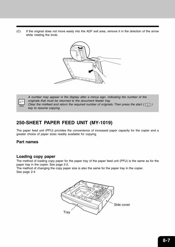
8-7
(C) If the original does not move easily into the ADF exit area, remove it in the direction of the arrowwhile rotating the knob.
A number may appear in the display after a minus sign, indicating the number of theoriginals that must be returned to the document feeder tray.Clear the misfeed and return the required number of originals. Then press the start ( )key to resume copying.
250-SHEET PAPER FEED UNIT (MY-1019)
The paper feed unit (PFU) provides the convenience of increased paper capacity for the copier and agreater choice of paper sizes readily available for copying.
Part names
Loading copy paperThe method of loading copy paper for the paper tray of the paper feed unit (PFU) is the same as for thepaper tray in the copier. See page 2-2.The method of changing the copy paper size is also the same for the paper tray in the copier.See page 2-4
Tray
Side cover
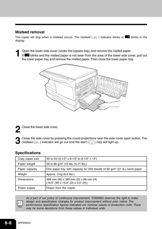
8-8 APPENDIX
Misfeed removalThe copier will stop when a misfeed occurs. The misfeed ( ) indicator blinks or blinks in thedisplay.
1 Open the lower side cover (under the bypass tray) and remove the misfed paper.If blinks and the misfed paper is not seen from the area of the lower side cover, pull outthe lower paper tray and remove the misfed paper. Then close the lower paper tray.
2 Close the lower side cover.
3 Close the side cover by pressing the round projections near the side cover open button. Themisfeed ( ) indicator will go out and the start ( ) key will light up.
SpecificationsCopy paper size A5 to A4 (5-1/2" x 8-1/2" to 8-1/2" x 14")
Paper weight 56 to 80 g/m2 (15 lbs. to 21 lbs.)
Paper capacity One paper tray with capacity for 250 sheets of 80 g/m2 (21 lb.) bond paper
Weight Approx. 3 kg (6.6 lbs.)
Dimensions 498 mm (W) x 395 mm (D) x 88 mm (H)(19.6" (W) x 15.6" (D) x 3.5" (H))
Power supply Drawn from the copier
As a part of our policy of continuous improvement, TOSHIBA reserves the right to makedesign and specification changes for product improvement without prior notice. Theperformance specification figures indicated are nominal values of production units. Theremay be some deviations from these values in individual units.
8-9
AAcrobat Reader .................................... 7-26, 7-27Alarm indicator
Developer replacement requiredindicator ........................................ 1-4, 6-3, 6-7Maintenance indicator ................. 1-4, 6-3, 6-7Misfeed indicator ......................... 1-4, 6-3, 6-4
Toner cartridge replacement requiredindicator ............................................. 1-4, 5-2, 6-3Appendix ........................................................... 8-2Auto clear time .................................................. 4-3Auto power shut-off mode ................................ 4-3Automatic exposure adjustment ...................... 3-7
BBefore installation ............................................ 7-3Button Manager .......................................7-2, 7-18Bypass ............................................................... 1-3Bypass feed ...................................................... 2-6Bypass tray guides ........................................... 1-3
CCautions
Handling .......................................................... 7Label ................................................................ 6Laser ................................................................ 7Using................................................................ 6
Charger cleaner ......................................... 1-3, 5-6Cleaning the unit
Cabinet ........................................................ 5-5Original cover .............................................. 5-5Original table ............................................... 5-5Transfer charger .......................................... 5-6
Clear key ............................................ 1-4, 3-6, 4-4Connecting the interface cable
Parallel interface cable ............................ 7-30USB interface cable .................................. 7-29
Conventions used in the manual .................... 1-2Copy flow .......................................................... 3-2Copy quantity .................................................... 3-6Copy quantity key .............................. 1-4, 3-6, 4-3Copy ratio display key ............................... 1-4, 3-8Copy ratio selector indicator ..................... 1-4, 3-8Copy ratio selector key .............................. 1-4, 3-8
INDEXDDark key ..................................................... 1-4, 3-7Developer replacement requiredindicator ............................................. 1-4, 6-3, 6-7Desktop Document Manager ........................... 7-2Developer required .......................................... 6-7Display .............................................................. 1-4Displaying total number of copies ................... 4-4
EExposure adjustment ....................................... 3-6Exposure mode indicator .......................... 1-4, 3-6Exposure mode selector key .................... 1-4, 3-6
FFlow of installation ............................................ 7-4Front cover ........................................................ 1-3Fusing unit release lever .......................... 1-3, 6-5
HHandle ............................................................... 1-3Hardware and softwarerequirements ..................................................... 7-3How to print ..................................................... 7-16How to use the online manual ....................... 7-26
IIndicators on the operation panel ................. 7-15Initial settings of operation panel .................... 3-4Installing the software ...................................... 7-2Interface
Parallel interface ....................................... 7-30USB interface ............................................ 7-29
Interrupt copying ............................................. 7-17Introduction ....................................................... 1-2
LLight and dark indicator ............................ 1-4, 3-6Light key ..................................................... 1-4, 3-7Loading paper .................................................. 2-2Loading the paper tray ..................................... 2-4
8-10 APPENDIX
MMaintenance indicator ...................... 1-4, 6-3, 6-7Making copies ................................................... 3-2MFP driver
Print Status Window ................................... 7-2Printer driver ................................................ 7-2Scanner driver ............................................. 7-2
Misfeed indicator ............................... 1-4, 6-3, 6-4Misfeed removal
Fusing area ................................................. 6-5Paper feed area .......................................... 6-5Transport area ............................................. 6-6
Multi-bypass ............................................... 1-3, 2-6
NName
Operation panel .......................................... 1-4Part names .................................................. 1-3
OONLINE indicator .....................................1-4, 7-15ONLINE key .............................................1-4, 7-15Online manual ................................................ 7-26Opening the printer driver .............................. 7-16Opening the scanner driver ........................... 7-23Operation panel ......................................... 1-3, 1-4Original placement ........................................... 3-5Original table .................................................... 1-3
PPaper ................................................................. 2-2Paper feed location indicators ......................... 1-4Paper output tray .............................................. 1-3Paper output tray extension ...................... 1-3, 3-2Paper tray ................................................... 1-3, 2-4Parallel interface cable ........................ 7-29, 7-30Photo copying ................................................... 3-6Power cord socket ............................................ 1-3Power off ........................................................... 3-4Power on ........................................................... 3-3Power save indicator ...............................1-4, 7-15Power switch .............................................. 1-3, 3-3Preheat mode ................................................... 4-3Proper storage ...................................................... 7
RReduction/enlargement/zoom ......................... 3-8
SScanner driver .................................................. 7-2Scanner indicator ....................................1-4, 7-15SCANNER key .........................................1-4, 7-22Scanning from your computer ....................... 7-23Scanning with the “Scanner andCamera Wizard” .............................................. 7-25Side cover ......................................................... 1-3Side cover open button .................................... 1-3Software for the TOSHIBA Personal MFPseries ................................................................. 7-2Specifications.................................................... 8-2Start indicator ...........................................1-4, 7-15Start key ............................................. 1-4, 3-2, 4-4Status indicators ............................................... 6-3
TToner cartridge ........................................... 1-3, 5-2Toner cartridge replacement ............................ 5-2Toner cartridge replacementindicator ............................................. 1-4, 5-2, 6-3Transfer charger ......................................... 1-3, 5-6Troubleshooting ................................................ 6-2Troubleshooting the unit .................................. 6-2
UUSB interface cable ....................................... 7-29Using other installed drivers .......................... 7-28Using the manual ............................................. 1-2Using the printer mode................................... 7-16Using the scanner mode ................................ 7-18Using the TOSHIBA TWAIN ............................ 7-23
ZZOOM indicator .......................................... 1-4, 3-8ZOOM key .................................................. 1-4, 3-8

8-11
SOFTWARE LICENSE
PLEASE READ THIS LICENSE CAREFULLY BEFORE USING THE SOFTWARE. BY USING THESOFTWARE, YOU ARE AGREEING TO BE BOUND BY THE TERMS OF THIS LICENSE.
1. License.The application, demonstration, system and other software accompanying this License, whether on disk, in read onlymemory, or on any other media (the “Software”) and related documentation are licensed to you by TOSHIBA. You ownthe disk on which the Software is recorded but TOSHIBA and/or TOSHIBA’S Licensors retain title to the Software andrelated documentation. This License allows you to use the Software on one or more computers connected to a singleprinter and make one copy of the Software in machine-readable form for backup purposes only. You must reproduce onsuch copy the TOSHIBA copyright notice, the copyright notice of TOSHIBA’S Licensors and any other proprietarylegends of TOSHIBA and/or its Licensors that were on the original copy of the Software. You may also transfer all yourlicense rights in the software, the backup copy of the Software, the related documentation and a copy of this License toanother party, provided the other party reads and agrees to the terms and conditions of this License.
2. Restrictions.The Software contains copyrighted material, trade secrets and other proprietary material which is owned by TOSHIBAand/or its Licensors and in order to protect them you may not decompile, reverse engineer, disassemble or otherwisereduce the Software to a human-perceivable form. You may not modify, network, rent, lease, loan, distribute or createderivative works based upon the Software in whole or in part. You may not electronically transmit the Software from onecomputer to another or over a network.
3. Termination.This license is effective until terminated. You may terminate this License at any time by destroying the Software andrelated documentation and all copies thereof. This License will terminate immediately without notice from TOSHIBAand/or TOSHIBA’S Licensors if you fail to comply with any provision of this License. Upon termination you mustdestroy the Software and related documentation and all copies thereof.
4. Export Law Assurances.You agree and certify that neither the Software nor any other technical data received from TOSHIBA, nor the directproduct thereof, will be exported outside the United States except as authorized and as permitted by the laws andregulations of the United States. If the Software has been rightfully obtained by you outside of the United States, you agreethat you will not re-export the Software nor any other technical data received from TOSHIBA, nor the direct productthereof, except as permitted by the laws and regulations of the United States and the laws and the regulation of thejurisdiction in which you obtained the Software.
5. Government End Users.If you are acquiring the Software on behalf of any unit or agency of the United States Government, the followingprovisions apply. The Government agrees:
(i) if the Software is supplied to the Department of Defense (DoD), the Software is classified as “CommercialComputer Software” and the Government is acquiring only “restricted rights” in the Software and its documentationas that term is defined in Clause 252.227-7013 (c)(1) of the DFARS; and
(ii) if the Software is supplied to any unit or agency of the United States Government other than DoD, the Government’srights in the Software and its documentation will be as defined in Clause 52.227-19 (c)(2) of the FAR or, in the caseof NASA, in Clause 18-52.227-86 (d) of the NASA Supplement to the FAR.
6. Limited Warranty on Media.TOSHIBA warrants the disks on which the Software is recorded to be free from defects in materials and workmanshipunder normal use for a period of ninety (90) days from the date of purchase as evidenced by a copy of the receipt. Theentire liability of TOSHIBA and/or its Licensors and your exclusive remedy will be replacement of the disk which fails tomeet the limited warranty provided by this Clause 6. A disk will be replaced when it is returned to TOSHIBA or aTOSHIBA authorized representative with a copy of the receipt. TOSHIBA will have no responsibility to replace a diskdamaged by accident, abuse or misapplication.
ANY IMPLIED WARRANTIES ON THE DISKS, INCLUDING THE IMPLIED WARRANTIES OFMERCHANTABILITY AND FITNESS FOR A PARTICULAR PURPOSE, ARE LIMITED IN DURATION TO NINETY(90) DAYS FROM THE DATE OF DELIVERY. THIS WARRANTY GIVES YOU SPECIFIC LEGAL RIGHTS, AND YOUMAY ALSO HAVE OTHER RIGHTS WHICH VARY FROM JURISDICTION TO JURISDICTION.

8-12 APPENDIX
7. Disclaimer of Warranty on Software.You expressly acknowledge and agree that use of the Software is at your sole risk. The software and related documentationare provided “AS IS” and without warranty of any kind and TOSHIBA and TOSHIBA’S Licensor(s) (for the purpose ofprovisions 7 and 8, TOSHIBA and TOSHIBA’S Licensor(s) shall be collectively referred to as “TOSHIBA”) EXPRESSLYDISCLAIM ALL WARRANTIES, EXPRESS OR IMPLIED, INCLUDING, BUT NOT LIMITED TO, THE IMPLIEDWARRANTIES OF MERCHANTABILITY AND FITNESS FOR A PARTICULAR PURPOSE. TOSHIBA DOES NOTWARRANT THAT THE FUNCTIONS CONTAINED IN THE SOFTWARE WILL MEET YOUR REQUIREMENTS, ORTHAT THE OPERATION OF THE SOFTWARE WILL BE UNINTERRUPTED OR ERROR-FREE, OR THAT DEFECTSIN THE SOFTWARE WILL BE CORRECTED. FURTHERMORE, TOSHIBA DOES NOT WARRANT OR MAKE ANYREPRESENTATIONS REGARDING THE USE OR THE RESULTS OF THE USE OF THE SOFTWARE OR RELATEDDOCUMENTATION IN TERMS OF THEIR CORRECTNESS, ACCURACY, RELIABILITY, OR OTHERWISE. NOORAL OR WRITTEN INFORMATION OR ADVICE GIVEN BY TOSHIBA OR A TOSHIBA AUTHORIZEDREPRESENTATIVE SHALL CREATE A WARRANTY OR IN ANY WAY INCREASE THE SCOPE OF THISWARRANTY. SHOULD THE SOFTWARE PROVE DEFECTIVE, YOU (AND NOT TOSHIBA OR A TOSHIBAAUTHORIZED REPRESENTATIVE) ASSUME THE ENTIRE COST OF ALL NECESSARY SERVICING, REPAIR ORCORRECTION, SOME JURISDICTIONS DO NOT ALLOW THE EXCLUSION OF IMPLIED WARRANTIES, SO THEABOVE EXCLUSION MAY NOT APPLY TO YOU.
8. Limitation of Liability.UNDER NO CIRCUMSTANCES INCLUDING NEGLIGENCE, SHALL TOSHIBA BE LIABLE FOR ANY INCIDENTAL,SPECIAL OR CONSEQUENTIAL DAMAGES THAT RESULT FROM THE USE OR INABILITY TO USE THESOFTWARE OR RELATED DOCUMENTATION, EVEN IF TOSHIBA OR A TOSHIBA AUTHORIZEDREPRESENTATIVE HAS BEEN ADVISED OF THE POSSIBILITY OF SUCH DAMAGES. SOME JURISDICTIONS DONOT ALLOW THE LIMITATION OR EXCLUSION OF LIABILITY FOR INCIDENTAL OR CONSEQUENTIALDAMAGES SO THE ABOVE LIMITATION OR EXCLUSION MAY NOT APPLY TO YOU.In no event shall TOSHIBA’S total liability to you for all damages, losses, and causes of action (whether in contract, tort(including negligence) or otherwise) exceed the amount paid by you for the Software.
9. Controlling Law and Severability.For a portion of the Software related with Apple Macintosh and Microsoft Windows, this license shall be governed by andconstrued in accordance with the laws of the state of California and Washington, respectively. If for any reason a courtof competent jurisdiction finds any provision of this License, or portion thereof, to be unenforceable, that provision ofthe License shall be enforced to the maximum extent permissible so as to effect the intent of the parties, and theremainder of this License shall continue in full force and effect.
10. Complete Agreement.This License constitutes the entire agreement between the parties with respect to the use of the Software and relateddocumentation, and supersedes all prior or contemporaneous understandings or agreements, written or oral, regarding suchsubject matter. No amendment to or modification of this License will be binding unless in writing and signed by a dulyauthorized representative of TOSHIBA.

Toshiba Tec Germany Imaging Systems GmbHCarl-Schurz-Str. 7
41460 NeussTelefon +49/(0)2131/1245-0Fax +49/(0)2131/1245-402www. toshiba-europe.com
2231253ENestudio120_150_EN.pdfestudio120_150 copier Manual EN